Embed Size (px)
Citation preview
07-DESIGN-042
Technology Readiness Assessment for the Waste Treatment and Immobilization Plant (WTP) Analytical Laboratory, Balance of Facilities and LAW Waste Vitrification Facilities L. Holton D. Alexander C. Babel H. Sutter J. Young March 2007 Prepared by the U.S. Department of Energy Office of River Protection Richland, Washington, 99352

07-DESIGN-042
Technology Readiness Assessment for the Waste Treatment and Immobilization Plant (WTP) Analytical Laboratory, Balance of Facilities and LAW Waste Vitrification Facilities L. Holton D. Alexander C. Babel H. Sutter J. Young March 2007 Prepared by the U.S. Department of Energy Office of River Protection under Contract DE-AC05-76RL01830

07-DESIGN-042
iii
Summary
The U.S. Department of Energy (DOE), Office of River Protection (ORP) and the DOE Office of Environmental Management (EM), Office of Project Recovery have completed a Technology Readiness Assessment (TRA) for three Hanford Waste Treatment and Immobilization Plant (WTP) facilities; Analytical Laboratory (LAB), Balance of Facilities (BOF), and Low-Activity Waste Vitrification Facility (LAW). The purpose of this assessment was to determine if the maturity of critical technology elements (CTE) is sufficient to be incorporated into the final design of these facilities.
The methodology used for this TRA was based upon detailed guidance for conducting TRAs contained in the Department of Defense, Technology Readiness Assessment Deskbook1. The assessment utilized a slightly modified version of the Technology Readiness Level (TRL) Calculator2 originally developed by Nolte et al. (2003) to determine the TRL for the CTE. Mr. Nolte was present during the initial TRA sessions and guided the Assessment Team through the use of the TRL Calculator; Mr. Nolte also reviewed this report.
The TRA consisted of three parts:
1. Identifying the CTEs
2. Assessing the TRLs of each CTE using the technical readiness scale used by the U.S. Department of Defense (DoD) and National Aeronautics and Space Administration (NASA), and adapted by the Assessment Team for use by DOE (Table S-1)
3. Evaluating, if required, technology testing or engineering work necessary to bring immature technologies to appropriate maturity levels.
CTEs are those technologies that are essential to successful operation of the facility, and are new or are being applied in new or novel ways or environments. The CTE identification process was based upon the definition of WTP systems and considered 20 systems from the LAB, 18 systems from BOF, and 32 systems from LAW. Seven of these were identified as CTEs as described below. An identification of systems evaluated and CTEs is presented in Appendix B.
• Two LAB systems were determined to be CTEs: the Autosampling System (ASX), and the Laser Ablation Inductively Coupled Plasma Mass Spectrometry/Laser Ablation Inductively Coupled Plasma Atomic Emission Spectrometry (LA-ICP-MS/LA-ICP-AES) subsystems of the Analytical Hot Cell Laboratory System (AHL), which provide the analytical equipment systems for the LAB.
• No BOF systems were judged to be CTEs because the BOF systems do not use new technologies, or do not use standard technologies in new or novel ways.
• Five LAW systems were determined to be CTEs: the LAW Melter Feed Process System (LFP) used to prepare the LAW melter feed; the LAW Melter System (LMP), which includes the LAW melter; the LAW Melter Offgas/Secondary Offgas and Vessel Vent Process Systems (LOP/LVP) used to treat the LAW melter offgas; the ILAW Container Finishing Handling System (LFH) container closure subsystem; and the LFH container decontamination subsystem.
1 Department of Defense, Technology Readiness Assessment (TRA) Deskbook, May 2005, prepared by the Deputy Undersecretary of Defense for Science and Technology (DUSD(S&T)). 2 Nolte, William L., et al., “Technology Readiness Level Calculator,” October 20, 2003, Air Force Research Laboratory, presented at the NDIA Systems Engineering Conference.
07-DESIGN-042
iv
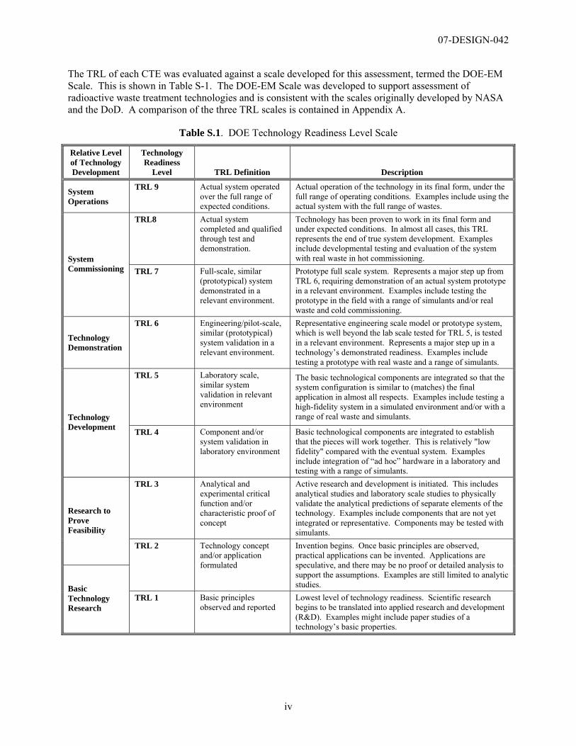
The TRL of each CTE was evaluated against a scale developed for this assessment, termed the DOE-EM Scale. This is shown in Table S-1. The DOE-EM Scale was developed to support assessment of radioactive waste treatment technologies and is consistent with the scales originally developed by NASA and the DoD. A comparison of the three TRL scales is contained in Appendix A.
Table S.1. DOE Technology Readiness Level Scale
Relative Level of Technology Development
Technology Readiness
Level TRL Definition Description
System Operations
TRL 9 Actual system operated over the full range of expected conditions.
Actual operation of the technology in its final form, under the full range of operating conditions. Examples include using the actual system with the full range of wastes.
TRL8 Actual system completed and qualified through test and demonstration.
Technology has been proven to work in its final form and under expected conditions. In almost all cases, this TRL represents the end of true system development. Examples include developmental testing and evaluation of the system with real waste in hot commissioning. System
Commissioning TRL 7 Full-scale, similar (prototypical) system demonstrated in a relevant environment.
Prototype full scale system. Represents a major step up from TRL 6, requiring demonstration of an actual system prototype in a relevant environment. Examples include testing the prototype in the field with a range of simulants and/or real waste and cold commissioning.
Technology Demonstration
TRL 6 Engineering/pilot-scale, similar (prototypical) system validation in a relevant environment.
Representative engineering scale model or prototype system, which is well beyond the lab scale tested for TRL 5, is tested in a relevant environment. Represents a major step up in a technology’s demonstrated readiness. Examples include testing a prototype with real waste and a range of simulants.
TRL 5 Laboratory scale, similar system validation in relevant environment
The basic technological components are integrated so that the system configuration is similar to (matches) the final application in almost all respects. Examples include testing a high-fidelity system in a simulated environment and/or with a range of real waste and simulants. Technology
Development TRL 4 Component and/or system validation in laboratory environment
Basic technological components are integrated to establish that the pieces will work together. This is relatively "low fidelity" compared with the eventual system. Examples include integration of “ad hoc” hardware in a laboratory and testing with a range of simulants.
TRL 3 Analytical and experimental critical function and/or characteristic proof of concept
Active research and development is initiated. This includes analytical studies and laboratory scale studies to physically validate the analytical predictions of separate elements of the technology. Examples include components that are not yet integrated or representative. Components may be tested with simulants.
Research to Prove Feasibility
TRL 2 Technology concept and/or application formulated
Invention begins. Once basic principles are observed, practical applications can be invented. Applications are speculative, and there may be no proof or detailed analysis to support the assumptions. Examples are still limited to analytic studies. Basic
Technology Research
TRL 1 Basic principles observed and reported
Lowest level of technology readiness. Scientific research begins to be translated into applied research and development (R&D). Examples might include paper studies of a technology’s basic properties.
07-DESIGN-042
v
The DoD and NASA normally require a TRL of 6 for incorporation of a technology into the design process. This is done based upon the recommendations of an influential report3 by the U.S. General Accounting Office (GAO) that examined the differences in technology transition between the DoD and private industry. It concluded that the DoD takes greater risks and attempts to transition emerging technologies at lesser degrees of maturity than private industry. The GAO also concluded that use of immature technology increased overall program risk and recommended that the DoD adopt the use of NASA’s TRLs as a means of assessing technology maturity prior to transition into final design. Based upon the precedence set by DOD, this assessment used TRL 6 as the basis for determining that a technology is sufficiently mature for incorporation into the final design.
A TRL Calculator was used to provide a structured and consistent assessment to determine the TRL of each CTE identified. The TRL Calculator tabulates responses to a standard set of questions addressing hardware, software, program, and manufacturability. The TRL Calculator is implemented in Microsoft Excel™ and produces a graphical display of the TRL achieved. It was adapted for this assessment by adding and modifying existing questions to make it more applicable to DOE waste treatment equipment and processes. The TRL Calculator is described in Appendix C. Specific responses to each of the TRL questions for the CTEs evaluated in this TRA are presented in Appendix D. The CTEs were not evaluated to determine if they had matured beyond TRL 6. The results of this TRL determination are presented in Table S-2.
The Assessment Team concluded that the critical technology elements of the LAB, BOF, and LAW facilities are sufficiently mature to continue to advance the final design of these facilities. However, based upon the results of this assessment, the following recommendations for specific technologies are made:
1. The prototypical Laser Ablation Inductively Coupled Plasma Atomic Emission Spectrometry (LA-ICP-AES) subsystem should be tested to demonstrate achievable detection limits for chemical elements of interest and satisfy turnaround time requirements on actual HLW sludge samples in a relevant environment to support the final design of the actual LAB subsystems. The LA-ICP-MS can be qualified in the Analytical Hot Cell system (AHL) after laser ablation technology has been implemented with ICP-AES in the AHL and is fully operational.
Testing is recommended to confirm that the design of the LA-ICP-AES will meet its functional requirements. Design optimization for AHL implementation should continue following demonstration of the prototype. This testing is included in the WTP baseline.
2. Integrated prototypic testing of the actual immobilized low-activity waste (ILAW) container inert filling, flange cleaning, inspection, and lidding/delidding equipment system in a simulated remote environment should be completed prior to installation in the LAW Vitrification Facility to verify that the equipment system will perform as required.
The mechanical processing steps of the container lidding sealing system used to seal the containers uses new equipment concepts that have not been previously tested in a remote operational environment. Waiting to complete the testing at cold commissioning represents a significant cost and schedule risk to the LAW Facility if the technology does not perform as intended. Fabrication acceptance testing is planned. However, this testing will not be prototypical of the remote operational environment.
3 GAO/NSIAD-99-162, Best Practices: Better Management of Technology Can Improve Weapon System Outcomes, July 1999, United States General Accounting Office.
07-DESIGN-042
vi
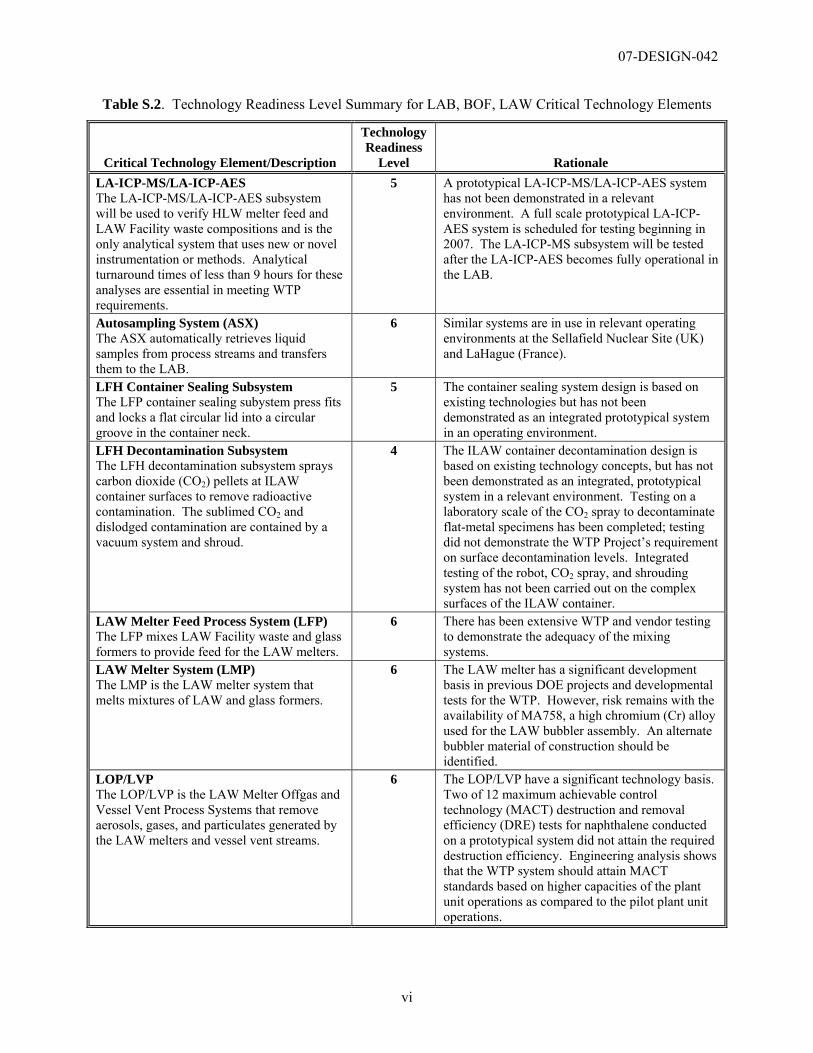
Table S.2. Technology Readiness Level Summary for LAB, BOF, LAW Critical Technology Elements
Critical Technology Element/Description
Technology Readiness
Level Rationale LA-ICP-MS/LA-ICP-AES The LA-ICP-MS/LA-ICP-AES subsystem will be used to verify HLW melter feed and LAW Facility waste compositions and is the only analytical system that uses new or novel instrumentation or methods. Analytical turnaround times of less than 9 hours for these analyses are essential in meeting WTP requirements.
5 A prototypical LA-ICP-MS/LA-ICP-AES system has not been demonstrated in a relevant environment. A full scale prototypical LA-ICP-AES system is scheduled for testing beginning in 2007. The LA-ICP-MS subsystem will be tested after the LA-ICP-AES becomes fully operational in the LAB.
Autosampling System (ASX) The ASX automatically retrieves liquid samples from process streams and transfers them to the LAB.
6 Similar systems are in use in relevant operating environments at the Sellafield Nuclear Site (UK) and LaHague (France).
LFH Container Sealing Subsystem The LFP container sealing subystem press fits and locks a flat circular lid into a circular groove in the container neck.
5 The container sealing system design is based on existing technologies but has not been demonstrated as an integrated prototypical system in an operating environment.
LFH Decontamination Subsystem The LFH decontamination subsystem sprays carbon dioxide (CO2) pellets at ILAW container surfaces to remove radioactive contamination. The sublimed CO2 and dislodged contamination are contained by a vacuum system and shroud.
4 The ILAW container decontamination design is based on existing technology concepts, but has not been demonstrated as an integrated, prototypical system in a relevant environment. Testing on a laboratory scale of the CO2 spray to decontaminate flat-metal specimens has been completed; testing did not demonstrate the WTP Project’s requirement on surface decontamination levels. Integrated testing of the robot, CO2 spray, and shrouding system has not been carried out on the complex surfaces of the ILAW container.
LAW Melter Feed Process System (LFP) The LFP mixes LAW Facility waste and glass formers to provide feed for the LAW melters.
6 There has been extensive WTP and vendor testing to demonstrate the adequacy of the mixing systems.
LAW Melter System (LMP) The LMP is the LAW melter system that melts mixtures of LAW and glass formers.
6 The LAW melter has a significant development basis in previous DOE projects and developmental tests for the WTP. However, risk remains with the availability of MA758, a high chromium (Cr) alloy used for the LAW bubbler assembly. An alternate bubbler material of construction should be identified.
LOP/LVP The LOP/LVP is the LAW Melter Offgas and Vessel Vent Process Systems that remove aerosols, gases, and particulates generated by the LAW melters and vessel vent streams.
6 The LOP/LVP have a significant technology basis. Two of 12 maximum achievable control technology (MACT) destruction and removal efficiency (DRE) tests for naphthalene conducted on a prototypical system did not attain the required destruction efficiency. Engineering analysis shows that the WTP system should attain MACT standards based on higher capacities of the plant unit operations as compared to the pilot plant unit operations.
07-DESIGN-042
vii
3. Integrated prototypic testing of the actual ILAW container decontamination and smear testing systems in a simulated remote environment should be completed following fabrication of equipment components to verify the equipment system will perform as required and will achieve the WTP Project-specified surface decontamination levels (less than 100 dpm/100 cm2 alpha and less than 1,000 dpm/100cm2 beta-gamma). This testing program should be supplemented with laboratory scale testing to define the operational parameters for the carbon dioxide (CO2) decontamination system.
The ILAW container decontamination subsystem relies on a localized surface decontamination approach using a CO2 pellet spray contained within a series of specialized shrouds. A robot is used to position the shrouds against the surfaces of the ILAW container. A vacuum is used to recover loosened contamination and sublimed CO2. Proof of concept testing using flat-metal coupons was completed. However, there remains a high risk that the removal of the contamination from the container oxide film will not be effective due to the complex shapes on the container design, and the requirement that the shroud system effectively contain loosened contamination. A loss of control of the removed contamination in the areas adjacent to the container decontamination station may result in re-contamination of the container. Subsequent decontamination of the work area may also result in impacts to the LAW Facility production.
Based upon the limited testing completed and the unique operating requirements for this system, there is a high probability that the current design concept may not perform as intended and will require significant design changes. Problems with this system may not be identified until hot commissioning of the LAW Facility. Design modifications at this time will be expensive and time consuming. An inability of the CO2 decontamination system to perform its function has the potential to shut down low-activity waste processing and the entire WTP.
The testing of the ILAW container decontamination subsystem should include testing with full scale containers at the anticipated operating temperatures. Particular attention in the testing program should be focused on the use of the localized decontamination shroud system and its ability to maintain contamination control and achieve full decontamination of the container. The ability of the shroud tools to decontaminate all container surfaces should be demonstrated.
4. It is recommended that a backup LAW melter bubbler design, using materials of construction other than the high nickel MA758 alloy be identified and qualified for use in the LAW melter.
This recommendation is based upon recent issues in fabricating acceptable MA758 alloy and risks identified by the WTP Contractor in the long term availability of this alloy.
WTP software and control systems were not included in this TRA.
This assessment is the first of several TRAs planned for the WTP. Additional TRAs are planned for the Pretreatment and HLW Facilities.

07-DESIGN-042
viii
Acknowledgement The Assessment Team wishes to thank Mr. William Nolte of the Air Force Research Laboratory for consultation, guidance, and direct support in the application of the NASA and DoD Technology Readiness Level (TRL) process to DOE’s first use of this process to the Waste Treatment and Immobilization Plant (WTP). Mr. Nolte also provided, and supported, the Assessment Team in the adaptation of a TRL Calculator that he authored, ensuring consistency between the NASA, DoD, and DOE applications of the TRL Assessment process.
07-DESIGN-042
ix
Contents
1.0 Introduction .....................................................................................................................................1-1 1.1 Background ............................................................................................................................1-1 1.2 Assessment Objectives ...........................................................................................................1-1 1.3 Description of TRA process ...................................................................................................1-1
1.3.1 Background ...............................................................................................................1-1 1.3.2 TRA Process..............................................................................................................1-2
2.0 TRL Assessment..............................................................................................................................2-1 2.1 TRL Process Description........................................................................................................2-1 2.2 Determination of CTEs ..........................................................................................................2-1 2.3 Summary of the Technology Readiness Assessment .............................................................2-2
2.3.1 Analytical Hot Cell Laboratory Equipment/Analytical Radiological Laboratory Equipment Systems (AHL/ARL) ..............................................................................2-3
2.3.2 Autosampling System (ASX)....................................................................................2-8 2.3.3 ILAW Container Finishing Handling System (LFH) Container Sealing
Subsystem................................................................................................................2-12 2.3.4 ILAW Container Finishing Handling System (LFH) Decontamination Subsystem2-15 2.3.5 LAW Melter Process System (LMP) ......................................................................2-19 2.3.6 LAW Melter Feed Process (LFP)............................................................................2-23 2.3.7 LAW Primary Offgas Process and Secondary Offgas Vessel Vent Process
Systems (LOP/LVP)................................................................................................2-26 3.0 Summary and Recommendations ....................................................................................................3-1
3.1 Summary ................................................................................................................................3-1 3.2 Recommendations ..................................................................................................................3-1
4.0 References .......................................................................................................................................4-1 Appendix A Technology Readiness Level Development and Definitions ...............................................A-1 Appendix B Determination of Critical Technology Elements .................................................................. B-1 Appendix C Technology Readiness Level Calculator as Modified for DOE Office of Environmental
Management ................................................................................................................................... C-1 Appendix D Technology Readiness Level Summary for WTP Critical Technology Elements for
LAB/BOF/LAW.............................................................................................................................D-1 Appendix E Participants in the TRL Assessment ..................................................................................... E-1
07-DESIGN-042
x
Figures
Figure 2.1. Schematic of the LA-ICP-AES Analytical Subsystem as Planned for the Prototype.............2-4 Figure 2.2. Schematic of the Autosampling System, Pneumatic Transfer System, and WTP Facilities ..2-9 Figure 2.3. ILAW Container Lidding Tool.............................................................................................2-13 Figure 2.4. Schematic of the ILAW Decontamination Station ...............................................................2-16 Figure 2.5. Isometric of the LAW Melter ...............................................................................................2-20 Figure 2.6. Process Schematic for LAW Melter Feed Process System (LFP)........................................2-24 Figure 2.7. Block Flow Diagram for the LAW primary Offgas Process System (LOP)/
LAW Secondary Offgas/Vessel Vent Process System (LVP) .........................................................2-27
Tables
Table 1.1. Technology Readiness Levels used in this Assessment...........................................................1-3 Table 1.2. Relationship of Testing Requirements to the TRL ..................................................................1-4 Table 2.1. Questions used to Determine the Critical Technology Element for the LAB/BOF/LAW
Technology Readiness Level Assessment .........................................................................................2-2 Table 3.1. Technology Readiness Level Summary for the LAB, BOF, and LAW Critical Elements......3-3
07-DESIGN-042
xi
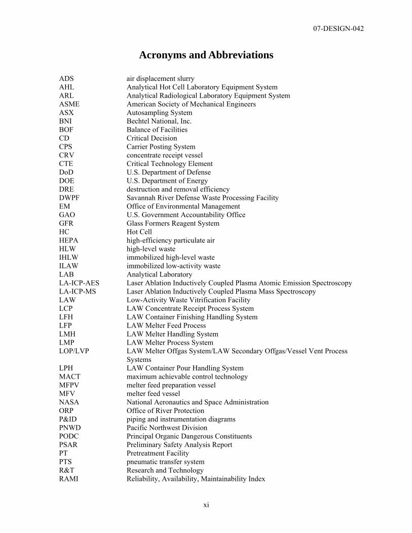
Acronyms and Abbreviations
ADS air displacement slurry AHL Analytical Hot Cell Laboratory Equipment System ARL Analytical Radiological Laboratory Equipment System ASME American Society of Mechanical Engineers ASX Autosampling System BNI Bechtel National, Inc. BOF Balance of Facilities CD Critical Decision CPS Carrier Posting System CRV concentrate receipt vessel CTE Critical Technology Element DoD U.S. Department of Defense DOE U.S. Department of Energy DRE destruction and removal efficiency DWPF Savannah River Defense Waste Processing Facility EM Office of Environmental Management GAO U.S. Government Accountability Office GFR Glass Formers Reagent System HC Hot Cell HEPA high-efficiency particulate air HLW high-level waste IHLW immobilized high-level waste ILAW immobilized low-activity waste LAB Analytical Laboratory LA-ICP-AES Laser Ablation Inductively Coupled Plasma Atomic Emission Spectroscopy LA-ICP-MS Laser Ablation Inductively Coupled Plasma Mass Spectroscopy LAW Low-Activity Waste Vitrification Facility LCP LAW Concentrate Receipt Process System LFH LAW Container Finishing Handling System LFP LAW Melter Feed Process LMH LAW Melter Handling System LMP LAW Melter Process System LOP/LVP LAW Melter Offgas System/LAW Secondary Offgas/Vessel Vent Process
Systems LPH LAW Container Pour Handling System MACT maximum achievable control technology MFPV melter feed preparation vessel MFV melter feed vessel NASA National Aeronautics and Space Administration ORP Office of River Protection P&ID piping and instrumentation diagrams PNWD Pacific Northwest Division PODC Principal Organic Dangerous Constituents PSAR Preliminary Safety Analysis Report PT Pretreatment Facility PTS pneumatic transfer system R&T Research and Technology RAMI Reliability, Availability, Maintainability Index
07-DESIGN-042
xii
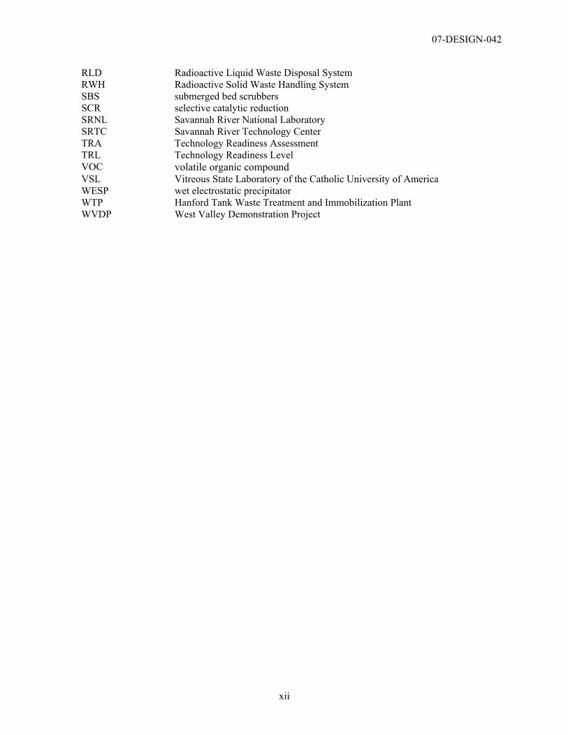
RLD Radioactive Liquid Waste Disposal System RWH Radioactive Solid Waste Handling System SBS submerged bed scrubbers SCR selective catalytic reduction SRNL Savannah River National Laboratory SRTC Savannah River Technology Center TRA Technology Readiness Assessment TRL Technology Readiness Level VOC volatile organic compound VSL Vitreous State Laboratory of the Catholic University of America WESP wet electrostatic precipitator WTP Hanford Tank Waste Treatment and Immobilization Plant WVDP West Valley Demonstration Project
07-DESIGN-042
xiii
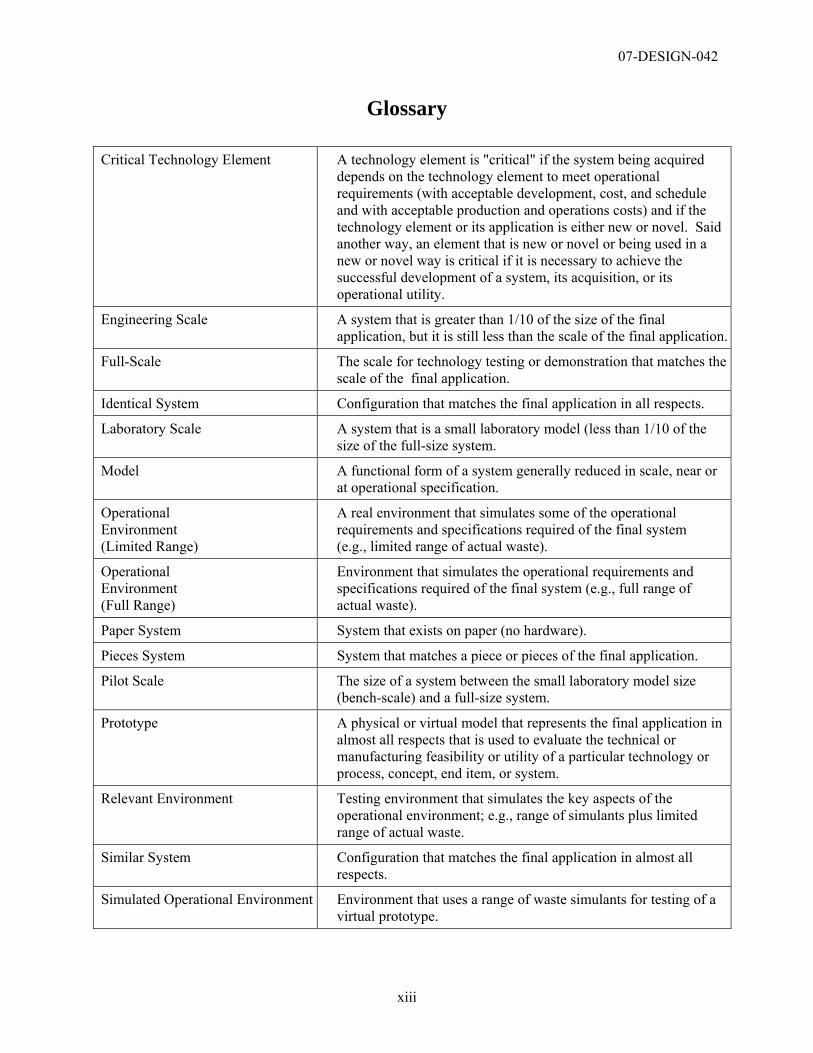
Glossary
Critical Technology Element A technology element is "critical" if the system being acquired depends on the technology element to meet operational requirements (with acceptable development, cost, and schedule and with acceptable production and operations costs) and if the technology element or its application is either new or novel. Said another way, an element that is new or novel or being used in a new or novel way is critical if it is necessary to achieve the successful development of a system, its acquisition, or its operational utility.
Engineering Scale A system that is greater than 1/10 of the size of the final application, but it is still less than the scale of the final application.
Full-Scale The scale for technology testing or demonstration that matches the scale of the final application.
Identical System Configuration that matches the final application in all respects.
Laboratory Scale A system that is a small laboratory model (less than 1/10 of the size of the full-size system.
Model A functional form of a system generally reduced in scale, near or at operational specification.
Operational Environment (Limited Range)
A real environment that simulates some of the operational requirements and specifications required of the final system (e.g., limited range of actual waste).
Operational Environment (Full Range)
Environment that simulates the operational requirements and specifications required of the final system (e.g., full range of actual waste).
Paper System System that exists on paper (no hardware).
Pieces System System that matches a piece or pieces of the final application.
Pilot Scale The size of a system between the small laboratory model size (bench-scale) and a full-size system.
Prototype A physical or virtual model that represents the final application in almost all respects that is used to evaluate the technical or manufacturing feasibility or utility of a particular technology or process, concept, end item, or system.
Relevant Environment Testing environment that simulates the key aspects of the operational environment; e.g., range of simulants plus limited range of actual waste.
Similar System Configuration that matches the final application in almost all respects.
Simulated Operational Environment Environment that uses a range of waste simulants for testing of a virtual prototype.

07-DESIGN-042
1-1
1.0 Introduction
1.1 Background The U.S Department of Energy (DOE), Office of River Protection (ORP) is constructing a Waste Treatment and Immobilization Plant (WTP) for the treatment and vitrification of the underground tank wastes stored at the Hanford Site in Washington State. The WTP Project is comprised of four major facilities: a Pretreatment (PT) Facility to separate the tank waste into high-level waste (HLW) and low-activity waste (LAW) process streams; a HLW Vitrification Facility to immobilize the HLW fraction; a LAW Vitrification Facility to immobilize the LAW fraction; and an Analytical Laboratory (LAB) to support the operations of all four treatment facilities. Additionally, there are the Balance of Facilities (BOF) operations that provide utilities and other support to the processing facilities. The WTP Project is DOE’s largest capital construction project with an estimated cost of $12.263 billion, and a project completion date of November 2019 (DOE 2006).
Issues associated with the maturity of technology in the WTP have been evaluated by independent DOE Review Teams and in DOE’s design oversight process. The most notable evaluation was the recently completed “Comprehensive External Review of the Hanford Waste Treatment Plant Flowsheet and Throughput” (CCN: 132846) completed in March 2006. This evaluation identified 28 separate technical issues, some of which had not been previously identified by the WTP Contractor or DOE. A number of these issues originated from limited understanding of the technologies that comprise the WTP flowsheet.
As a result of these reviews, and DOE’s desire to more effectively manage the technology risks associated with the WTP, the DOE has decided to conduct a Technology Readiness Assessment (TRA) to assess the technical maturity of the WTP design. This TRA is patterned after guidance established by the U.S. Department of Defense (DoD) (DoD 2005) for conducting TRAs.
1.2 Assessment Objectives The purpose of this TRA is to evaluate the technologies used in three major facilities of the WTP: LAB, BOF, and LAW. This TRA is intended to:
• Identify Critical Technology Elements (CTE)
• Determine the TRL associated with the CTEs
• Provide recommendations on how to improve the maturity level of technologies that require additional development.
The TRA was performed jointly by DOE ORP and the DOE Office of Environmental Management (EM), Office of Project Recovery.
1.3 Description of TRA process
1.3.1 Background “A TRA is a systematic, metric-based process and accompanying report that assesses the maturity of certain technologies [called Critical Technology Elements (CTEs)] used in systems.” ( DoD 2005)
In 1999, the U.S. General Accounting Office (GAO) produced an influential report (GAO/NSIAD-99-162) that examined the differences in technology transition between the DoD and private industry.
07-DESIGN-042
1-2
The GAO concluded that the DoD took greater risks, and attempted to transition emerging technologies at lesser degrees of maturity compared to private industry and that the use of immature technology increased overall program risk and led to substantial cost and schedule overruns. The GAO recommended that the DoD adopt the use of National Aeronautics and Space Administration’s (NASA) Technology Readiness Levels (TRL) as a means of assessing technology maturity prior to design transition (see Appendix A for further discussion).
In 2001, the Deputy Undersecretary of Defense for Science and Technology issued a memorandum that endorsed the use of TRLs in new major programs. Guidance for assessing technology maturity was incorporated into the Defense Acquisition Guidebook (DODI 5000.2). Subsequently, the DoD developed detailed guidance for using TRLs in the 2003 DoD Technology Readiness Assessment Deskbook (updated in May 2005 [DOD 2005]). The DoD Milestone Decision Authority must certify to Congress that the technology has been demonstrated in a relevant environment prior to transition of weapons system technologies to design or justify any waivers. TRL 6 is also used as the level required for technology insertion into design by NASA. (See Appendix A for the DoD and NASA TRL definitions.)
Based upon historical use of the TRA process, the DOE has decided to use the DoD TRA process as a method for assessing technology readiness for the WTP.
1.3.2 TRA Process The TRA process as defined by the DoD consists of three parts: (1) identifying the CTEs; (2) assessing the TRLs of each CTE using an established readiness scale; and (3) preparing the TRA report. If some of the CTEs are judged to be below the desired level of readiness, the TRA is followed by development of a Technology Maturation Plan that identifies the additional development required to attain the desired level of readiness. The process is usually carried out by a group of experts that are independent of the project under consideration.
The CTE identification process involves breaking the project under evaluation into its component systems and subsystems, and determining which of these are essential to project success and either represent new technologies, combinations of existing technologies in new or novel ways, or will be used in a new environment. Appendix B describes the CTE process in detail.
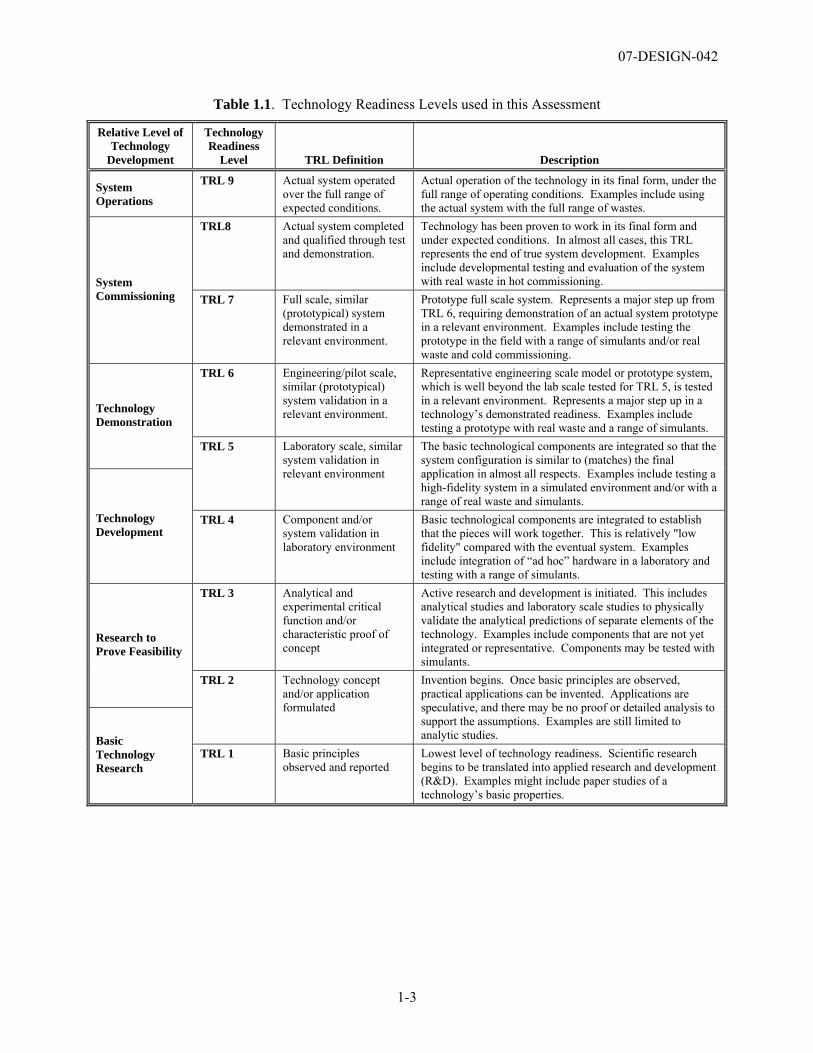
The TRL scale used in this assessment is shown in Table 1.1. This scale requires that testing of a prototypical design in a relevant environment be completed prior to incorporation of the technology into the final design of the facility.
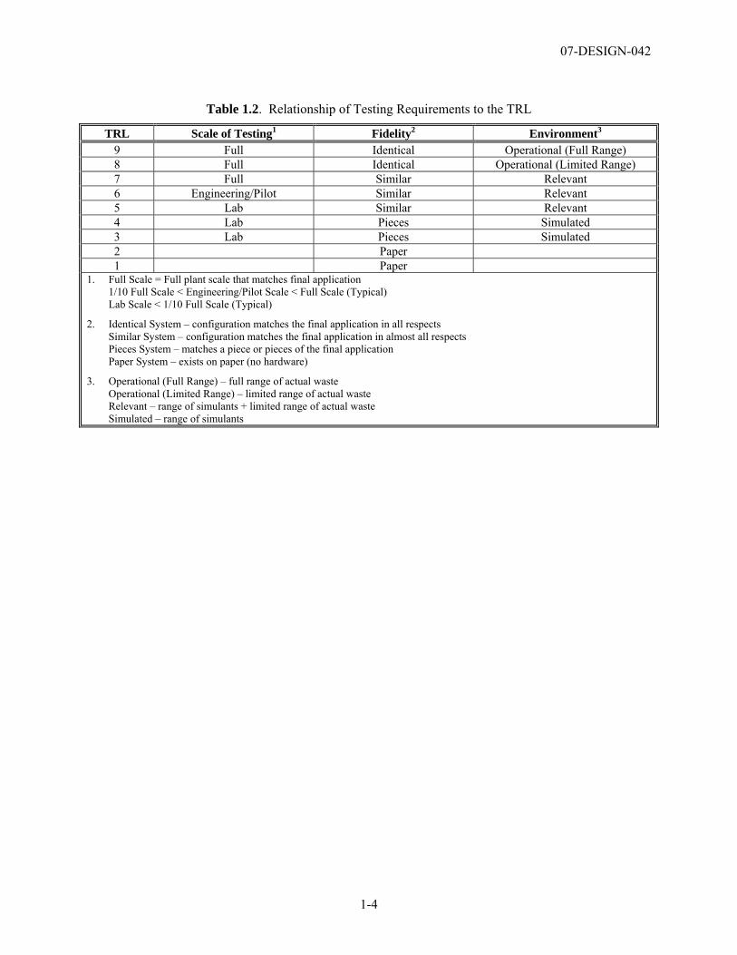
The testing requirements used in this assessment are compared to the TRLs in Table 1.2. These definitions provide a convenient means to understand further the relationship between the scale of testing, fidelity of testing system, and testing environment and the TRL. This scale requires that for a TRL 6 testing must be completed at an engineering or pilot scale, with a testing system fidelity that is similar to the actual application and with a range of simulated wastes and/or limited range of actual waste, if applicable.
The assessment of the TRLs was aided by a TRL Calculator that was originally developed by the U.S. Air Force (Nolte et al. 2003), and modified by the Assessment Team. This tool is a standard set of questions addressing hardware, software, program, and manufacturability questions that is implemented in Microsoft Excel™. The TRL Calculator produces a graphical display of the TRLs achieved. The TRL Calculator used in this assessment is described in more detail in Appendix C.
07-DESIGN-042
1-3
Table 1.1. Technology Readiness Levels used in this Assessment
Relative Level of Technology
Development
Technology Readiness
Level TRL Definition Description
System Operations
TRL 9 Actual system operated over the full range of expected conditions.
Actual operation of the technology in its final form, under the full range of operating conditions. Examples include using the actual system with the full range of wastes.
TRL8 Actual system completed and qualified through test and demonstration.
Technology has been proven to work in its final form and under expected conditions. In almost all cases, this TRL represents the end of true system development. Examples include developmental testing and evaluation of the system with real waste in hot commissioning. System
Commissioning TRL 7 Full scale, similar (prototypical) system demonstrated in a relevant environment.
Prototype full scale system. Represents a major step up from TRL 6, requiring demonstration of an actual system prototype in a relevant environment. Examples include testing the prototype in the field with a range of simulants and/or real waste and cold commissioning.
TRL 6 Engineering/pilot scale, similar (prototypical) system validation in a relevant environment.
Representative engineering scale model or prototype system, which is well beyond the lab scale tested for TRL 5, is tested in a relevant environment. Represents a major step up in a technology’s demonstrated readiness. Examples include testing a prototype with real waste and a range of simulants.
Technology Demonstration
TRL 5 Laboratory scale, similar system validation in relevant environment
The basic technological components are integrated so that the system configuration is similar to (matches) the final application in almost all respects. Examples include testing a high-fidelity system in a simulated environment and/or with a range of real waste and simulants.
Technology Development
TRL 4 Component and/or system validation in laboratory environment
Basic technological components are integrated to establish that the pieces will work together. This is relatively "low fidelity" compared with the eventual system. Examples include integration of “ad hoc” hardware in a laboratory and testing with a range of simulants.
TRL 3 Analytical and experimental critical function and/or characteristic proof of concept
Active research and development is initiated. This includes analytical studies and laboratory scale studies to physically validate the analytical predictions of separate elements of the technology. Examples include components that are not yet integrated or representative. Components may be tested with simulants.
Research to Prove Feasibility
TRL 2 Technology concept and/or application formulated
Invention begins. Once basic principles are observed, practical applications can be invented. Applications are speculative, and there may be no proof or detailed analysis to support the assumptions. Examples are still limited to analytic studies. Basic
Technology Research
TRL 1 Basic principles observed and reported
Lowest level of technology readiness. Scientific research begins to be translated into applied research and development (R&D). Examples might include paper studies of a technology’s basic properties.
07-DESIGN-042
1-4
Table 1.2. Relationship of Testing Requirements to the TRL
TRL Scale of Testing1 Fidelity2 Environment3 9 Full Identical Operational (Full Range) 8 Full Identical Operational (Limited Range) 7 Full Similar Relevant 6 Engineering/Pilot Similar Relevant 5 Lab Similar Relevant 4 Lab Pieces Simulated 3 Lab Pieces Simulated 2 Paper 1 Paper
1. Full Scale = Full plant scale that matches final application 1/10 Full Scale < Engineering/Pilot Scale < Full Scale (Typical) Lab Scale < 1/10 Full Scale (Typical)
2. Identical System – configuration matches the final application in all respects Similar System – configuration matches the final application in almost all respects Pieces System – matches a piece or pieces of the final application Paper System – exists on paper (no hardware)
3. Operational (Full Range) – full range of actual waste Operational (Limited Range) – limited range of actual waste Relevant – range of simulants + limited range of actual waste Simulated – range of simulants
07-DESIGN-042
2-1
2.0 TRL Assessment
2.1 TRL Process Description An Assessment Team comprised of staff from the DOE ORP, and technical consultants to ORP, and DOE EM’s Office of Project Recovery completed the TRL assessment (see Appendix E for the identification of the Assessment Team and supporting contractor staff from the WTP). The Assessment Team staff has worked on the Hanford WTP Project and related nuclear waste treatment and immobilization technologies for more than 60 years, and is independent of the WTP design and construction project. The Assessment Team was assisted by William Nolte of the Air Force Research Laboratory, Wright Patterson AFB, who was present for the initial CTE and TRL evaluation sessions and guided the Assessment Team through the use of the TRL Calculator. Mr. Nolte also reviewed and commented on this report.
The WTP engineering staff (e.g., WTP Project Team) presented descriptions of the WTP systems that were assessed, participated in the identification of the CTEs, and participated in the completion of responses to individual questions in the TRL Calculator. Each response to a specific Calculator question was recorded along with references to the appropriate WTP Project documents. The Assessment Team also completed independent due-diligence reviews and evaluation of the testing and design information to validate input obtained in the Assessment Team and WTP Project Team working sessions. The Calculator results for each CTE can be found in Appendix D.
This Assessment Team evaluated the process and mechanical systems that are used to treat and immobilize the radioactive waste to complete the preparation of the immobilized low-activity waste (ILAW) product for disposal. The team did not evaluate the software systems used to control the process and mechanical equipment because these software systems have not been sufficiently developed and are not critical to the mechanical design of the facilities. The assessment of the technology readiness of the software systems will be completed at a later date.
2.2 Determination of CTEs The process for identification of the CTEs for the LAB/BOF/LAW facilities involved two steps:
1. An initial screening by the Assessment Team of the complete list of systems in the LAB, BOF, and LAW facilities for those that have a potential to be a CTE. In this assessment, systems that are directly involved in the processing of the tank waste or handling of the primary products (ILAW and secondary wastes) were initially identified as potential CTEs. The complete list of systems and those identified as potential CTEs are provided in Appendix B, Tables B.1, B.2, and B.3 for the LAB, BOF, and LAW facilities, respectively.
2. A final screening of the potential CTEs was completed by the Assessment and WTP Project teams to determine the final set of CTEs for evaluation. The potential CTEs were evaluated against the two set of questions presented in Table 2.1. A system is determined to be a CTE if a positive response is provided to at least one of the questions in each of the two sets of questions.
07-DESIGN-042
2-2
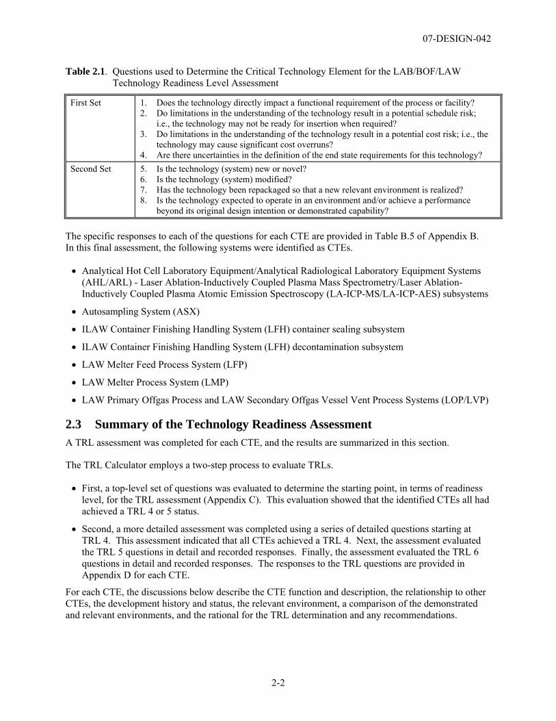
Table 2.1. Questions used to Determine the Critical Technology Element for the LAB/BOF/LAW Technology Readiness Level Assessment
First Set 1. Does the technology directly impact a functional requirement of the process or facility? 2. Do limitations in the understanding of the technology result in a potential schedule risk;
i.e., the technology may not be ready for insertion when required? 3. Do limitations in the understanding of the technology result in a potential cost risk; i.e., the
technology may cause significant cost overruns? 4. Are there uncertainties in the definition of the end state requirements for this technology?
Second Set 5. Is the technology (system) new or novel? 6. Is the technology (system) modified? 7. Has the technology been repackaged so that a new relevant environment is realized? 8. Is the technology expected to operate in an environment and/or achieve a performance
beyond its original design intention or demonstrated capability?
The specific responses to each of the questions for each CTE are provided in Table B.5 of Appendix B. In this final assessment, the following systems were identified as CTEs.
• Analytical Hot Cell Laboratory Equipment/Analytical Radiological Laboratory Equipment Systems (AHL/ARL) - Laser Ablation-Inductively Coupled Plasma Mass Spectrometry/Laser Ablation-Inductively Coupled Plasma Atomic Emission Spectroscopy (LA-ICP-MS/LA-ICP-AES) subsystems
• Autosampling System (ASX)
• ILAW Container Finishing Handling System (LFH) container sealing subsystem
• ILAW Container Finishing Handling System (LFH) decontamination subsystem
• LAW Melter Feed Process System (LFP)
• LAW Melter Process System (LMP)
• LAW Primary Offgas Process and LAW Secondary Offgas Vessel Vent Process Systems (LOP/LVP)
2.3 Summary of the Technology Readiness Assessment A TRL assessment was completed for each CTE, and the results are summarized in this section.
The TRL Calculator employs a two-step process to evaluate TRLs.
• First, a top-level set of questions was evaluated to determine the starting point, in terms of readiness level, for the TRL assessment (Appendix C). This evaluation showed that the identified CTEs all had achieved a TRL 4 or 5 status.
• Second, a more detailed assessment was completed using a series of detailed questions starting at TRL 4. This assessment indicated that all CTEs achieved a TRL 4. Next, the assessment evaluated the TRL 5 questions in detail and recorded responses. Finally, the assessment evaluated the TRL 6 questions in detail and recorded responses. The responses to the TRL questions are provided in Appendix D for each CTE.
For each CTE, the discussions below describe the CTE function and description, the relationship to other CTEs, the development history and status, the relevant environment, a comparison of the demonstrated and relevant environments, and the rational for the TRL determination and any recommendations.
07-DESIGN-042
2-3
2.3.1 Analytical Hot Cell Laboratory Equipment/Analytical Radiological Laboratory Equipment Systems (AHL/ARL)
2.3.1.1 Function of the AHL and ARL
The AHL is planned for supporting sample preparation and analysis of radioactive samples from the HLW and PT Facilities. The ARL is for supporting sample preparation and analysis of radioactive samples from the LAW Facility and certain AHL samples from hot cells. The evaluation of the critical technology elements for the AHL and ARL Equipment Systems (Appendix B) identified the LA-ICP-AES/LA-ICP-MS as CTE subsystems. The LA-ICP-AES system ablates and analyzes particulates from the surface of a prepared glass coupon (which will be prepared from waste stream samples) for elemental species in the waste streams. The LA-ICP-MS system similarly provides results for elemental and isotopic species in waste streams.
2.3.1.2 Description of the LA-ICP-MS and LA-ICP-AES Subsystems within the AHL/ARL
The AHL and ARL are two systems that provide analytical services to the WTP. The systems are defined in terms of the analytical equipment that is planned for installation into each system area. The LA-ICP-MS and LA-ICP-AES are the only analytical systems planned for use in the AHL that are not fully developed and verified with radioactive sample material. Laser ablation will first be applied to the ICP-AES in the AHL. The current ARL design basis for analytical support to LAW utilizes acid dissolution and alkali fusions for sample preparation. Both wet chemistry procedures are conventional methods routinely used in DOE fuel processing and waste treatment facilities.
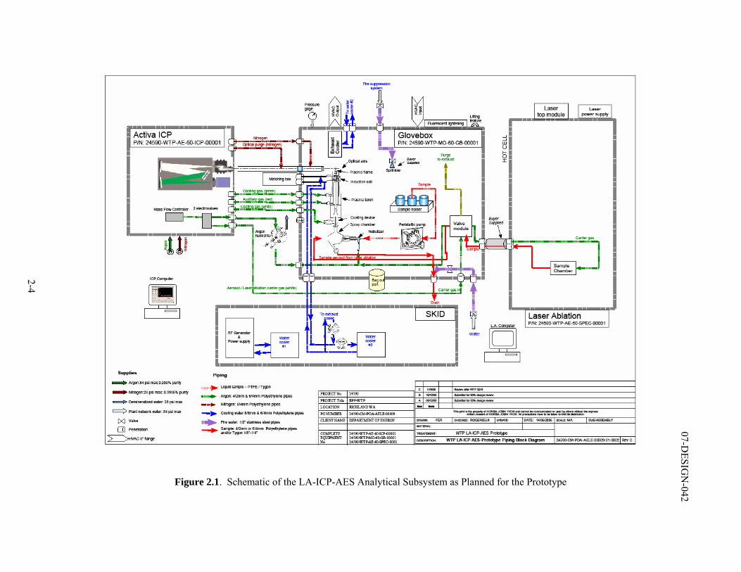
A schematic of the LA-ICP-AES subsystem as planned in a prototype is shown in Figure 2.1. Radioactive samples are first converted to a glass sample in a specially designed sample preparation furnace. The purpose of solidifying the sample is to simplify handling and to produce a homogenous sample for analysis. The cooled glass sample is subjected to a laser (e.g., laser ablation to “vaporize” sample material). An optical view system is used to observe and align the glass coupon for ablation. The vapor from the laser ablation is then drawn into an Atomic Emission Spectrometer for subsequent chemical and radiochemical analysis. Each of the individual components of the LA-ICP-AES subsystem is commercially available. However, the integration of these components to support a routine, radioactive, production scale analysis is unique to the WTP.
The LA-ICP-AES in the AHL will be used to analyze high-level waste (HLW) samples. Use of the LA-ICP-MS in the AHL is being considered after the LA-ICP-AES is fully operational in the LAB. The ICP-MS would backup the LA-ICP-AES subsystems for the AHL to ensure availability. The LA-ICP-AES technique will be used for elemental analysis, and it can be used for isotopic analysis when used in combination with traditional radiochemical counting techniques. The ICP-MS would be used for elements with low concentrations and isotopic analysis.
2-4
07-DESIG
N-042
Figure 2.1. Schematic of the LA-ICP-AES Analytical Subsystem as Planned for the Prototype
07-DESIGN-042
2-5
The laser ablation sample preparation and analysis techniques were selected for application in the WTP because the analysis turnaround time associated with LA-ICP-AES technology is significantly shorter than traditional wet chemistry techniques (24950-WTP-RPT-0P-06-001, Rev. 0). In current and previous DOE waste processing plants (West Valley Demonstration Project [WVDP] and Savannah River Defense Waste Processing Facility [DWPF]), radiochemical chemical sample analysis of melter feeds was completed by dissolving the slurry by acid dissolution, converting the slurry to glass or dissolving the glass with a caustic fusion (both potassium [K] and sodium [Na]), and analyzing the dilute fusion solutions using ICP AES technologies. A fusion using both potassium hydroxide (KOH) and NaOH must be completed so that the interference associated with the Na can be characterized, and a complete analysis of the solution completed for the cations in the waste. The LA-ICP technology for sample preparation avoids the requirement for extensive wet chemistry sample preparation that can reduce the total sample analysis turnaround time.
2.3.1.3 Relationship to Other Systems
The ICP-MS and ICP-AES subsystems are integral components of AHL and ARL. The AHL is a set of 14 hot cells (HC) with the ICP-MS and ICP-AES subsystems integrated with HCs 12 and 13. A laser system is planned in a hot cell that will ablate particles from the surface of a glass coupon. The laser ablation system will be applied to the ICP-AES, but procedures may be developed that support laser ablation for the ICP-MS if needed. The ARL consists of 13 radiochemical laboratories with the ICP-MS and ICP-AES subsystems integrated into two of these laboratories. Wet chemistry dissolution methods will be used to prepare samples in AHL and ARL. If the dose rate of prepared or received samples is low, then the samples can be transferred to the ARL from the AHL facility (for analysis or preparation and analysis) for managing sample load.
The development and implementation of the LA-ICP-AES in the AHL is required to support rapid turnaround-time requirements for HLW melter feed preparation vessel samples. Achieving the relatively short sample analysis turnaround time for the HLW samples is essential to support the operations of the HLW Facility at the specified waste treatment capacity and thereby support continuous operations. Based upon current planning in the Integrated Sampling and Analysis Requirements Document, the AHL and ARL will be required to analyze approximately 10,000 samples per year. More than a third of these samples, about 3,700 samples per year are projected for collection from the HLW Facility melter feed preparation vessels (MFPV).
2.3.1.4 Development History and Status
Initial feasibility tests of the LA-ICP-AES and LA-ICP-MS systems were completed by the WTP Project in two independent studies conducted at Savannah River National Laboratory (SRNL) and Battelle Pacific Northwest Division (PNWD). The studies supported development of two approaches for providing the required elemental analyses of HLW melter feed samples: (1) optimization of conventional dissolution of samples followed by elemental analyses of solutions by ICP-AES to support rapid turnaround time requirements; and (2) laser ablation of samples followed by ICP-AES elemental analyses of the ablated material. Studies involving LA-ICP-MS were included mainly to evaluate the applicability of ICP-MS analysis to ablation of HLW sludge matrix samples. The PNWD study (24590-101-TSA-W000-0004-158-00002) evaluated the capability of the LA-ICP-AES and the LA-ICP-MS to provide sufficient sample turnaround time, accuracy, and precision for HLW processing within the WTP. Tests were performed on dried melter feed simulants and analytical reference glasses. For the LA-ICP-AES, only two analytes exceeded 30% of the wet chemistry values, Na was 31% high and zinc (Zn) was 70% low. For the LA-ICP-MS, Zn was low and elements below atomic mass unit (amu) 43.6 (aluminum [Al], K, magnesium [Mg], Na, silicon [Si], and phosphorus [P]) were not analyzed because of spectral ion interferences.
07-DESIGN-042
2-6
The results of SRNL tests conducted in two phases are documented in two reports (SCT-M0SRLE60-00-216-00001, Rev. 00A; SCT-M0SRLE60-00-216-00002, Rev. 00A). The SRNL work scope included the demonstration of laser ablation and cold sample preparation methods with HLW simulants (Phase I) to the demonstration of laser ablation and cold sample preparation methods with an actual HLW sludge matrix under remote conditions (Phase II). Due to extenuating circumstances, laser ablation of the radioactive samples in Phase II could only be analyzed using LA-ICP-MS. SRNL concluded that the testing successfully demonstrated laser ablation as a sample preparation technique for radioactive glass samples, and that LA-ICP-AES and LA-ICP-MS were feasible for analysis of the Hanford Site tank waste composition. LA-ICP-MS was most suited for elemental analysis of low concentrations as well as radionuclide isotopes. Approaches and results of method development are summarized in a report issued by WTP (CCN: 146465).
Based on WTP method development work and previous PNNL testing, sufficient information was available to proceed with prototype LA-ICP-AES specifications for WTP testing to optimize the final design of the laser ablation sample preparation system. The WTP Project has initiated a full scale test (CCN: 139427) in the Hanford 222-S Laboratory to verify and validate LA-ICP-AES analytical method for hot samples. The task involves: (a) installation and testing of a WTP-procured LA-ICP-AES glovebox system properly configured in the adjacent hot cell for remotely ablating HLW samples, and (b) adaptation of the developed LA-ICP-AES method to routine operational requirements. This LA-ICP-AES subsystem will be a full scale prototype of the WTP plant system to analyze actual tank waste. Results of the LA-ICP-AES tests will be applicable for configuring laser ablation unit to the ICP-MS system after establishing the LA-ICP-AES to support the HLW Facility.
2.3.1.5 Relevant Environment
The relevant environment for laboratory subsystems is described in the AHL system description (24590-LAB-3YD-AHL-00001) and the ARL system description (24590-LAB-3YD-ARL-00001). Requirements unique to the laser ablation unit are described in the AHL system description (24590-LAB-3YD-AHL-00001). The planned implementation for LA-ICP-AES subsystem is described as follows:
• The LA-ICP-AES subsystem shall operate for the WTP in the AHL.
• The LA-ICP-AES subsystem shall measure the suite of elements in the HLW melter feeds required for glass formulation.
• The LA-ICP-AES subsystem in the AHL shall be operated remotely in hot cells and gloveboxes to analyze highly radioactive samples.
• Before LA-ICP-AES analysis, AHL samples shall be converted to a homogenous glass solid that is representative of the melter feed.
• The uncertainties associated with the analytical measurement using LA-ICP-AES shall be low enough to ensure that acceptable waste glass is formed.
• After laser ablation technology has been implemented with ICP-AES in the AHL and is fully operational, it may be applied to ICP-MS in the AHL.
2.3.1.6 Comparison of the Relevant Environment and the Demonstrated Environment
The LA-ICP-AES subsystem has not been demonstrated in a relevant environment. The LA-ICP-AES technology is a unique application of existing commercially available technologies that require testing of integrated system for measurement accuracy and development of analytical procedures for rapid turnaround time in a remote operating environment. This includes confirmation that analytical results
07-DESIGN-042
2-7
from the LA-ICP-AES system are comparable to ICP-AES results from samples prepared using well-developed wet chemistry dissolution technologies.
Component integration for the LA-ICP-AES will be demonstrated in the prototypic test planned in Hanford’s 222S Laboratory (CCN: 139427). This test will compare wet chemistry sample preparation techniques versus laser ablation as a sample preparation technique, and determine the accuracy of the LA-ICP-AES analysis compared to traditional ICP-AES analysis for HLW melter feed and glass samples. The tests will be conducted using LA-ICP-AES prototype equipment operating remotely in hot cells and gloveboxes. The tests will demonstrate whether the LA-ICP-AES turnaround time requirements can be met in a remote environment using manipulators. Results will provide information on the achievable turnaround times and limits of detection for the LA-ICP-AES.
The LA-ICP-AES testing will use actual HLW tank waste sludge samples for testing the developed analytical procedure and prototype performance to ensure that the subsystem will produce reliable and consistent analytical results. Selected analytes of interest from the HLW Compliance Plan (24590-WTP-PL-RT-03-002) and the immobilized high-level waste (IHLW) Formulation Algorithm documentation (24590-HLW-RPT-RT-05-001) include: antimony, aluminum, boron, cadmium, magnesium, sulfur, manganese, thallium, nickel, thorium, phosphorous, titanium, chromium, iron, lithium, silicon [S], zinc, sodium [Na], zirconium, strontium, calcium, potassium [K], and uranium. Other analytes will be tested as part of ongoing methods development for the WTP.
The laser ablation technique for sample preparation for ICP-AES and ICP-MS methods are not planned for near term use to support LAW Vitrification, because the turnaround requirements for LAW vitrification allow the use of conventional wet chemistry methods for sample preparation. If LA-ICP-AES is used to support glass formulation for LAW vitrification, it must accurately measure cations associated with Na2O, K2O, and SO3 that limit the loading of low-activity waste in glass (24590-LAW-RPT-04-0003). Radionuclide related constraints are satisfied by process control activities.
2.3.1.7 Technology Readiness Level Determination
The AHL was determined to be a TRL 5 because the high-fidelity prototype of the LA-ICP-AES analytical subsystem has not been tested in a relevant environment. Integrated prototypical testing of a full-scale LA-ICP-AES is planned at the Hanford 222-S Hot Cell Facility beginning in calendar year 2007 (CCN: 139427) to verify the final design concept prior to the completion of the design of the actual full scale LA-ICP-AES subsystems for AHL facility.
Recommendation 1
The prototypical LA-ICP-AES system should be tested to demonstrate achievable detection limits for chemical elements of interest and satisfy turnaround time requirements on actual HLW sludge samples in a relevant environment to support the final design of the actual LAB subsystems. The LA-ICP-MS can be qualified in the AHL after laser ablation technology has been implemented with ICP-AES in the AHL and is fully operational.
Testing is recommended to confirm that the design of the LA-ICP-AES will meet its functional requirements. Design optimization for AHL implementation should continue following demonstration of the prototype. This testing is included in the WTP baseline.
07-DESIGN-042
2-8
2.3.2 Autosampling System (ASX)
2.3.2.1 Function of the Autosampling System (ASX)
The ASX is designed to remotely collect representative radioactive process liquid samples from designated process vessels at each of the WTP process facilities (PT/LAW/HLW), and transfer those samples via a pneumatic transfer system (PTS) to the LAB for analysis.
2.3.2.2 Description of ASX System
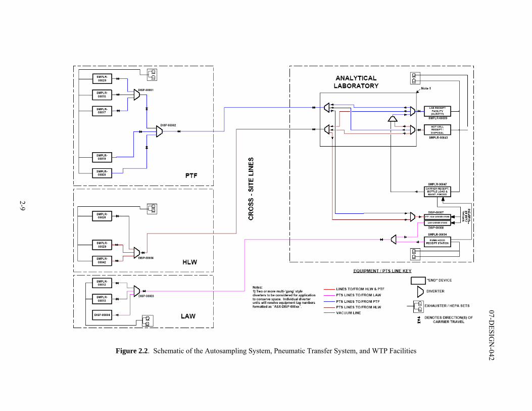
The ASX is described in the ASX system description (24590-WTP-3YD-ASX-00001). The ASX is comprised of 10 autosamplers with supporting remote manipulators located inside specially designed gloveboxes; sample bottle and carrier systems; and the PTS, comprised of transfer piping, 4 diverters (routing valves integral to the transfer piping), 3 LAB receipt stations, PTS exhausters, and a standalone carrier posting system (CPS) station. A schematic layout of the ASX and its relationship to the WTP facilities is shown in Figure 2.2. A brief description of the ASX for each facility is given below:
• The ASX is designed for remote operation inside the central control room of the Pretreatment (PT) Facility.
• The PT Facility houses five autosampler stations. The PT Facility samples are transported to the hot cell (HC) receipt station 00039 in the LAB.
• The HLW Facility houses three autosampler stations. The HLW samples are transported to the HC receipt station 00043 located in the LAB.
• The LAW Facility houses two autosampler stations and a CPS. The LAW samples are transported to a fume hood receipt station 00034 located in the LAB.
• The LAB houses two HC receipt stations and one fume hood receipt station.
Each of the 10 autosampler stations includes a remote manipulator used to position sample bottles under a commercially available autosampler device (ISOLOCK sampler 4). Sample bottles with unique labels and carriers are introduced into the autosampler stations thru a magazine loading station. Recirculation process fluid lines having diameters that vary between 2 to 3 inches from the vessels to be sampled will be routed into identified autosampler station.
Once a sample event is initiated for a specific vessel, the following steps occur:
• A pumping system is activated that recirculates process fluid/slurry between the vessel and the autosampling station.
• The remote manipulator removes a new sample bottle from the carrier and places it on the ISOLOCK sampler.
• A sample is obtained from the process stream by the ISOLOCK sampler, in 15 to 35 mL increments, to fill the sample bottle.
4 Manufactured by Sentry Equipment Corporation.
2-9
07-DESIG
N-042
Figure 2.2. Schematic of the Autosampling System, Pneumatic Transfer System, and WTP Facilities
07-DESIGN-042
2-10
• Once filled, the sample bottle is retracted slightly, and the sampler needle is flushed and vented.
• The filled sample bottle is placed in a sample carrier by the remote manipulator and the carrier is pneumatically transferred to the LAB.
The technology being evaluated as the CTE is the complete ASX.
The design and fabrication of the ASX is being completed by a commercial vendor (EnergySolutions) previously responsible for the design of the autosampling system for the THORP Nuclear Fuel Reprocessing facility at the Sellafield Site. Bechtel National, Inc. (BNI), the WTP Contractor, is designing the software for the control of this system.
2.3.2.3 Relationship to Other Systems
The ASX supports the operation of the WTP facilities by obtaining and transferring process solution samples to the LAB for analysis. The information from the sample analysis is essential for the operation of the WTP facilities. These sample results are used to confirm that the process fluid compositions are within the safety authorization basis assumptions, control process operation conditions, and control waste loading in the final ILAW and IHLW glass products.
The representativeness of the sample and the accuracy of the sample analysis are critical to the quality of the data obtained from the sample. The representativeness of the sample is dependent upon the homogeneity of the process solution being sampled and is directly related to the performance of the solution mixing systems for each vessel. The accuracy of the sample analysis results is directly related to the analysis techniques and procedures used in the LAB. These system interfaces, although critical to the analytical results, do not directly affect the performance of the ASX.
2.3.2.4 Development History and Status
The design and planned operation of the ASX for the WTP are based on designs used at the THORP Nuclear Fuel Reprocessing Plant at the Sellafield Site, UK and the LaHague Nuclear Reprocessing Plants, France (NHC-8373; NHC-8374; NHC-8375). These operating facilities reprocess spent nuclear fuel. The sampling systems are used for the sampling of process waste streams, which have radiation levels several orders of magnitude greater that the waste streams in the WTP.
The ISOLOCK sampler design being used in the WTP is a proven design that has been previously, and is currently, used in the nuclear, chemical, and food industry. The WTP Project will be adapting commercially available ISOLOCK samplers into specifically designed WTP glovebox design configurations.
2.3.2.5 Relevant Environment
Operating requirements are identified in the ASX system description (24590-WTP-3YD-ASX-00001) and the design requirements in the autosampler engineering specification (24590-WTP-3PS-MHSS-T0002, Rev. 0). The relevant environment of the ASX is:
• Use of the equipment systems with radioactive waste solutions that vary between low radiation and high radiation solutions, with low and high solids concentration waste slurries
• Remote operation of the sampling and transfer equipment
• High operational availability of the equipment systems required to support WTP process operations.
07-DESIGN-042
2-11
The WTP Project’s design of these systems is consistent with previous applications of the technologies. A unique challenge discussed during this evaluation is the need to characterize the mixing of sampling slurries with the solids level of the WTP to understand if samples meet requirements for representativeness, and to determine how many samples are needed to provide measurements sufficient for process control and product quality verification.
2.3.2.6 Comparison of the Relevant Environment and the Demonstrated Environment
The ASX was demonstrated in a relevant environment. A comparison of the relevant environment and the demonstrated environment shows that the extensive use of an autosampling system at similar facilities is applicable to the demonstration of the final WTP design configuration in a relevant environment.
Automatic sampling systems are used at the THORP plant, Sellafield, UK, the LaHague fuel reprocessing facilities, France, and the DWPF at the Savannah River Site, South Carolina, in high radiation environments. The samplers used in the THORP plant (ISOLOCK) are from the same manufacturer as those proposed for use in the WTP and have an almost identical. Both the Sellafield and LaHague sites employ sampling systems that are automated and operated from a central control room. The Savannah River Site does not use a needle and seal for samples as in the ISOLOCK design, but uses a customized cup that is mounted on the head of the piston drive. Seals and needles similar to the WTP design are used at the THORP plant for radioactive, high solids, slurry streams.
Energy Solutions, the vendor for the ASX, completed testing of Hanford’s ISOLOCK sampler using WTP-simulated waste compositions in their fabrication shop (24590-QL-HC4-HAHH-00001-05-00002). Additional shop testing of the autosampling equipment systems, including functional testing of the instruments and control systems using BNI developed software, is planned. A fully integrated test of the autosampler, PTS transfer system, receipt station, and exhauster systems will be performed during shop testing (24590-WTP-3PS-MHSS-T0002). Shop tests will be controlled using prototypic WTP control hardware and software to verify system performance and to make any required changes prior to installation in the WTP facilities.
DOE recently conducted a design oversight of the ASX (06-WTP-105) to evaluate the design in relationship to its functional and operational requirements. This study identified several design deficiency issues including system redundancy (enabling the system to function during maintenance or partial system failures), retrieval of broken or stuck sample carriers in the PTS; adequacy of shielding in the autosampler station and parts of the PTS; estimates of system availability; and software testing. However, these are design, not technology, issues; their resolution is part of the ongoing effort to finalize the ASX design.
The DOE Design Oversight Report (06-WTP-105) noted that additional testing of the equipment and software during cold and hot commissioning of the WTP may be required because the ASX relies heavily on automated systems for operation and control. Based on the results of this oversight, it is recognized that the design of the ASX is not complete and design issues unique to the WTP design are planned for resolution. A summary of the risks associated with the design is summarized in CCN: 133570, “Concurrence of ASX Risks and Risk Mitigation Strategy.”
2.3.2.7 Technology Readiness Level Determination
The ASX was determined to be TRL 6 because there has been an extensive use of the remotely operated autosampling technology components in other relevant operating conditions at the Sellafield Nuclear Site, UK, and the LaHague Nuclear Site, France. The WTP design is being adapted from these design concepts.
07-DESIGN-042
2-12
2.3.3 ILAW Container Finishing Handling System (LFH) Container Sealing Subsystem
2.3.3.1 Function of the LFH Container Sealing Subsystem
The LFH receives the glass-filled ILAW containers from the ILAW Container Pour Handling System (LPH). The LFH performs the following functions required to ready the container for export from the LAW Facility and subsequent burial: weighing, glass-level determination, inert filling, container closure, container decontamination, container smear testing, and container radiation dose rate measurement.
The evaluation of the CTEs for the LFH (Appendix B) identified the ILAW container sealing subsystem as a CTE. The container sealing subsystem requires that the container be sealed to prevent the dispersal of radioactive contamination during the most severe conditions encountered during normal use and handling. The closure system must be designed to ensure that the seal remains intact for a storage period of 50 years in an ambient-temperature ventilated enclosure. The WTP Project use of subsystem technology is a unique application of exiting commercially available technologies and custom designs that when integrated result in a new technology system.
2.3.3.2 Description of the ILAW Container Sealing Subsystem
The ILAW container sealing subsystem is described in the system description for the LFH (24590-LAW-3YD-LFH-00001). The lidding process involves verification that the container-sealing surfaces are clean, and that the remote placement and sealing of the mechanical lid are complete.
The ILAW container flange is first visually inspected for debris by direct viewing through a shield window, and indirect viewing using remote cameras. If required, the container seal surface can be cleaned with power tools using a remote manipulator.
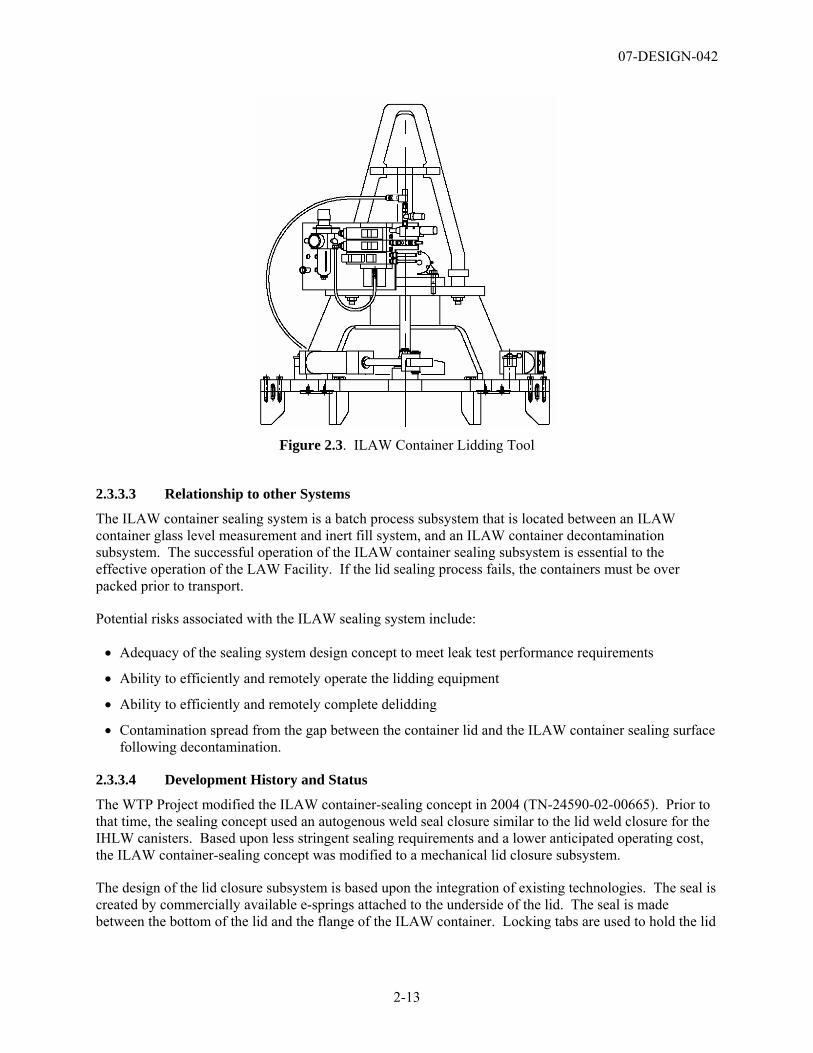
The filled ILAW container is closed and sealed by a mechanical lid and seal closure assembly. The assembly consists of a solid stainless steel lid with a metallic sealing ring attached to the bottom surface. The lid has spring-loaded locking bars located in slots on the lid side. A specialized lidding tool (Figure 2.3) has been designed to retrieve lids from a storage rack, and remotely place and seal the lid on the container. As the lid is pressed into position on the container flange sealing-surface, the bars first retract and then snap into a mating groove on the flange neck. The compressed sealing ring provides the pressure to maintain the closure seal. The seal compression is approximately 4,000 lb.
Visual verification of the position of the locking bars is used to confirm that the lid is correctly placed and sealed on the container.
A companion lid recovery tool has also been designed to remove an incompletely sealed, or damaged and installed lid. If the lid requires removal, the lid recovery tool can grab the container flange, push down on the lid, and release the locking bars. Pistons on the lid recovery tool allow an arm to rotate and grab the lid. The container flange surfaces can be cleaned and the lid reattached. Glass or inert fill found in the seal area can be removed with a seal preparation tool.
The LAW Facility has two ILAW lidding stations located as mirror images to each other. This was done to provide redundancy if one of the lidding stations is inoperable. The lidding equipment systems are designed for contact maintenance, which can occur following the removal of ILAW containers from the area.
07-DESIGN-042
2-13
Figure 2.3. ILAW Container Lidding Tool
2.3.3.3 Relationship to other Systems
The ILAW container sealing system is a batch process subsystem that is located between an ILAW container glass level measurement and inert fill system, and an ILAW container decontamination subsystem. The successful operation of the ILAW container sealing subsystem is essential to the effective operation of the LAW Facility. If the lid sealing process fails, the containers must be over packed prior to transport.
Potential risks associated with the ILAW sealing system include:
• Adequacy of the sealing system design concept to meet leak test performance requirements
• Ability to efficiently and remotely operate the lidding equipment
• Ability to efficiently and remotely complete delidding
• Contamination spread from the gap between the container lid and the ILAW container sealing surface following decontamination.
2.3.3.4 Development History and Status
The WTP Project modified the ILAW container-sealing concept in 2004 (TN-24590-02-00665). Prior to that time, the sealing concept used an autogenous weld seal closure similar to the lid weld closure for the IHLW canisters. Based upon less stringent sealing requirements and a lower anticipated operating cost, the ILAW container-sealing concept was modified to a mechanical lid closure subsystem.
The design of the lid closure subsystem is based upon the integration of existing technologies. The seal is created by commercially available e-springs attached to the underside of the lid. The seal is made between the bottom of the lid and the flange of the ILAW container. Locking tabs are used to hold the lid
07-DESIGN-042
2-14
with the compressed seal in place. The WTP design incorporates specialized lidding tools to position and seal the lid, and to remove an incompletely sealed or damaged and installed lid.
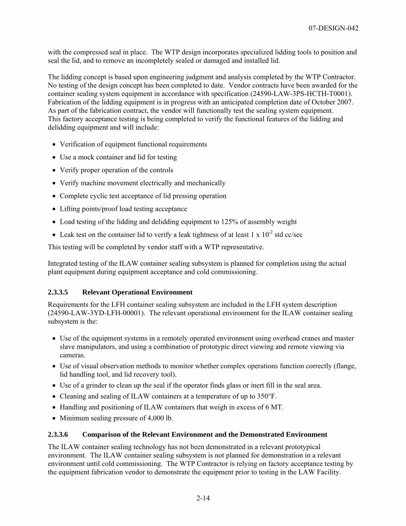
The lidding concept is based upon engineering judgment and analysis completed by the WTP Contractor. No testing of the design concept has been completed to date. Vendor contracts have been awarded for the container sealing system equipment in accordance with specification (24590-LAW-3PS-HCTH-T0001). Fabrication of the lidding equipment is in progress with an anticipated completion date of October 2007. As part of the fabrication contract, the vendor will functionally test the sealing system equipment. This factory acceptance testing is being completed to verify the functional features of the lidding and delidding equipment and will include:
• Verification of equipment functional requirements
• Use a mock container and lid for testing
• Verify proper operation of the controls
• Verify machine movement electrically and mechanically
• Complete cyclic test acceptance of lid pressing operation
• Lifting points/proof load testing acceptance
• Load testing of the lidding and delidding equipment to 125% of assembly weight
• Leak test on the container lid to verify a leak tightness of at least 1 x 10⁻² std cc/sec
This testing will be completed by vendor staff with a WTP representative.
Integrated testing of the ILAW container sealing subsystem is planned for completion using the actual plant equipment during equipment acceptance and cold commissioning.
2.3.3.5 Relevant Operational Environment
Requirements for the LFH container sealing subsystem are included in the LFH system description (24590-LAW-3YD-LFH-00001). The relevant operational environment for the ILAW container sealing subsystem is the:
• Use of the equipment systems in a remotely operated environment using overhead cranes and master slave manipulators, and using a combination of prototypic direct viewing and remote viewing via cameras.
• Use of visual observation methods to monitor whether complex operations function correctly (flange, lid handling tool, and lid recovery tool).
• Use of a grinder to clean up the seal if the operator finds glass or inert fill in the seal area. • Cleaning and sealing of ILAW containers at a temperature of up to 350°F. • Handling and positioning of ILAW containers that weigh in excess of 6 MT. • Minimum sealing pressure of 4,000 lb.
2.3.3.6 Comparison of the Relevant Environment and the Demonstrated Environment
The ILAW container sealing technology has not been demonstrated in a relevant prototypical environment. The ILAW container sealing subsystem is not planned for demonstration in a relevant environment until cold commissioning. The WTP Contractor is relying on factory acceptance testing by the equipment fabrication vendor to demonstrate the equipment prior to testing in the LAW Facility.
07-DESIGN-042
2-15
2.3.3.7 Technology Readiness Level Determination
The ILAW container sealing subsystem was determined to be a TRL 5 because a high-fidelity prototype of the sealing system has not been fabricated and tested in a relevant remote environment. The WTP Project is relying on the verification of the design concept as part of equipment component testing after installation in the LAW Facility.
Limited testing of the container sealing system is planned by the vendor (24590-LAW-3PS-HCTH-T0001) to verify portions of the final design concept as part of the shop acceptance of the equipment. However, integrated testing of the equipment system is not planned prior to cold commissioning.
Recommendation 2
Integrated prototypic testing of the actual immobilized low-activity waste (ILAW) container inert filling, flange cleaning, inspection, and lidding/delidding equipment system in a simulated remote environment should be completed prior to installation in the LAW Vitrification Facility to verify that the equipment system will perform as required.
2.3.4 ILAW Container Finishing Handling System (LFH) Decontamination Subsystem
2.3.4.1 Function of the LFH Decontamination Subsystem
The LFH receives the glass-filled ILAW containers from the LAW Container Pour Handling System (LPH). The LFH performs the following functions required to ready the container for export from the LAW Facility and subsequent burial: weighing, glass level determination, inert filling, container closure, container decontamination, container smear testing, and container radiation dose rate and temperature measurement.
The evaluation of the CTEs for the LFH (Appendix B) identified the ILAW container decontamination subsystem as a CTE. The function of the container decontamination subsystem is to remove radioactive contamination from filled and sealed ILAW container to a smearable contamination level less than 100 dpm/100 cm2 alpha and less than 1,000 dpm/100cm2 beta-gamma to allow movement of the containers to a truck lock (24590-WTP-DB-ENG-01-001, Table 5.2)
2.3.4.2 Description of the ILAW Container Decontamination Subsystem
The ILAW container decontamination subsystem is described in the system description for the LFH (24590-LAW-3YD-LFH-00001). The decontamination process uses abrasion to remove smearable radioactive contamination from the external surfaces of the sealed ILAW container. The abrasive media are solid CO2 pellets. The CO2 abrasion process uses a localized decontamination approach in which the CO2 spray is applied through spray nozzles located inside a containment shroud. The shroud is designed to contain the CO2 vapor (from sublimation of the solid CO2) and the loose radioactive contamination. The CO2 and the loose contamination are continuously removed from the shroud using a vacuum system. The contamination is packaged as solid waste.
The sealed ILAW container is positioned by an overhead crane and a specially designed boggie equipped with a turntable to provide access to all container surfaces for decontamination. The bottom of the container is decontaminated prior to placement on the boggie.
Once on the boggie, the sides and top of the container are decontaminated. The shroud system is positioned against the container by a specially designed robot. Several shapes of shrouds are being
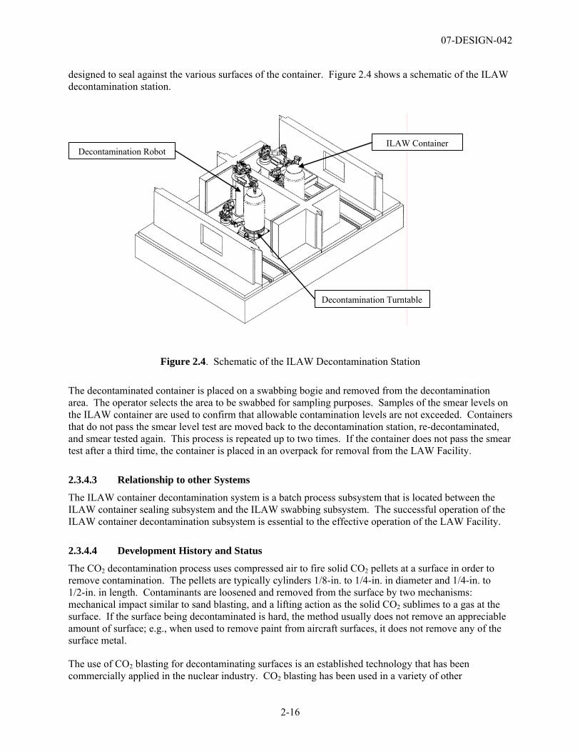
07-DESIGN-042
2-16
designed to seal against the various surfaces of the container. Figure 2.4 shows a schematic of the ILAW decontamination station.
Figure 2.4. Schematic of the ILAW Decontamination Station
The decontaminated container is placed on a swabbing bogie and removed from the decontamination area. The operator selects the area to be swabbed for sampling purposes. Samples of the smear levels on the ILAW container are used to confirm that allowable contamination levels are not exceeded. Containers that do not pass the smear level test are moved back to the decontamination station, re-decontaminated, and smear tested again. This process is repeated up to two times. If the container does not pass the smear test after a third time, the container is placed in an overpack for removal from the LAW Facility.
2.3.4.3 Relationship to other Systems
The ILAW container decontamination system is a batch process subsystem that is located between the ILAW container sealing subsystem and the ILAW swabbing subsystem. The successful operation of the ILAW container decontamination subsystem is essential to the effective operation of the LAW Facility.
2.3.4.4 Development History and Status
The CO2 decontamination process uses compressed air to fire solid CO2 pellets at a surface in order to remove contamination. The pellets are typically cylinders 1/8-in. to 1/4-in. in diameter and 1/4-in. to 1/2-in. in length. Contaminants are loosened and removed from the surface by two mechanisms: mechanical impact similar to sand blasting, and a lifting action as the solid CO2 sublimes to a gas at the surface. If the surface being decontaminated is hard, the method usually does not remove an appreciable amount of surface; e.g., when used to remove paint from aircraft surfaces, it does not remove any of the surface metal.
The use of CO2 blasting for decontaminating surfaces is an established technology that has been commercially applied in the nuclear industry. CO2 blasting has been used in a variety of other
ILAW Container Decontamination Robot
Decontamination Turntable
07-DESIGN-042
2-17
applications including paint removal from metal surfaces. Basic equipment such as CO2 pelletizers, delivery systems, and nozzles are standard, off-the-shelf equipment. CO2 pellets can be obtained in bulk commercially. Conversations with representatives of two commercial companies that use the technology for decontaminating radioactive surfaces indicate that the technology is very effective for removal of loose surface contamination, but it is not effective if the contamination is tightly adhered to the surface or covered by a tightly adhering layer5.
The WTP Contractor performed non-prototypical laboratory scale tests on 2 in. by 4 in., contaminated, flat coupons of the stainless steel that will be used for the ILAW container (SCT-M0SRLE60-00-99-07, SCT-M0SRLE60-00-110-12). Testing involved radioactive cesium (Cs) that had been vapor deposited on the coupon surface followed by a heat treatment cycle to mimic the thermal history of the container surface. Cesium was successfully removed by CO2 blasting to below system traditional non-smearable contamination levels (surface contamination less than 220 dpm/100 cm2 alpha and less than 2,200 dpm/ 100cm2 beta-gamma). However, the technique was not always successful at removing radioactive Cs that had been deposited on the coupon as a liquid solution. These tests did not employ a shroud system to contain the CO2 and removed contamination. No engineering scale prototypical tests of the WTP system have been completed. In addition, the testing did not confirm that the WTP Project contamination surface levels of less than 100 dpm/100 cm2 alpha and less than 1,000 dpm/100cm2 beta-gamma could be achieved.
The design of the ILAW container decontamination subsystem is based upon limited testing, engineering analysis and commercially available design concepts, e.g., robots and limited technology testing. The engineering specification for fabrication of the equipment includes the boggie and robot for the decontamination system (24590-LAW-3PS-HDYR-T0001) and requires the vendor to shop test portions of the equipment system. However, no integrated testing of all components of the LAW decontamination system is planned until the equipment is installed in the LAW Facility. Full scale decontamination of a ILAW container is not planned until hot commissioning.
2.3.4.5 Relevant Environment
The operating environment for the LFH container decontamination subsystem is specified in the WTP Basis of Design (24590-WTP-DB-ENG-01-001, Rev. 1C), the LFH system description (24590-LAW-3YD-LFH-00001, Rev. 1), and the LAW Preliminary Safety Analysis Report (PSAR) (24590-WTP-PSAR-ESH-01-002-03, Rev. 1). The relevant operational environment for the ILAW container contamination subsystem is:
• Operating the system shall prevent the release of contamination outside of the shroud system. • Operator control of the decontamination system shall ensure that all surfaces are adequately
decontaminated. • Equipment systems in a remotely operated environment shall use overhead cranes and master/slave
manipulators, and a combination of prototypic direct viewing and remote viewing via cameras lines of sight and angles.
• Decontamination shall transport, clean, and swab ILAW containers having surface temperature of up to 350°F.
• The crane and grapple shall handle and position ILAW containers that weigh in excess of 6 MT.
5 Personal communication between H. Sutter and J. Wilson, UniTech Services Group, Inc., Springfield, MA; W. Briggs, Master-Lee Decon Services, Latrobe, PA, January 3, 2007.
07-DESIGN-042
2-18
• Shrouds around the various nozzle assemblies shall provide containment for removed contaminants during the decontamination operation.
• Swabbing robots shall access the top, side, and bottom areas. • The decontamination room shall be clean enough after decontamination for container to be released. • The decontamination system shall provide for disposal of solid waste. • Rotating hooks shall not be degraded because of crane decontamination; therefore, sealed bearings
will be used.
2.3.4.6 Comparison of the Relevant Environment and the Demonstrated Environment
The system has not been demonstrated in a relevant prototype environment. The ILAW container decontamination equipment has been tested on a laboratory scale in a simulated environment. Only a few pieces of the decontamination system have been tested. These include the use of the CO2 spray to decontaminate simulated contaminated metal test specimens. The integrated CO2 spray and shrouding system has not been tested
CO2 blasting will be used to decontaminate the containers that have been filled with molten LAW glass at approximately 1100°C and have surface temperatures of approximately 700°C (24590-101-TSA-W000-0009-101-00007). The most likely contaminant is radioactive Cs. The most likely transfer mechanism for Cs contamination will be by vapor-phase deposition, although the possibility does exist for direct contamination through spills and spatters of glass. The ILAW container is a right cylinder of dimension 7.5 ft high with a 4-ft diameter and a neck with a press fit lid. The decontamination system will consist of a robotically controlled blasting nozzle and a shrouding system that will use a vacuum to capture CO2 and contamination.
Although the CO2 blast system has been used in many applications in the nuclear and other industries, the Assessment Team is not aware of any application that is similar to the proposed WTP system in terms of the thermal history of the contaminated surface, the configuration of the container, and the local shrouding system. The lab scale system used for the Savannah River Site specimen decontamination tests (SCT-M0SRLE60-00-99-07, SCT-M0SRLE60-00-110-12) was non-prototypical. These tests used 2-in. by 4-in. flat coupons of the container material. Half the coupons were contaminated by direct placement of a solution of radioactive Cs. These coupons were then heat-treated in an oven to a temperature of 950°C with an equivalent number of clean coupons that became contaminated by vapor deposition. The 950°C temperature was at least 200°C higher than the highest temperatures recorded during prototypical ILAW container pours carried out at Duratek Federal Services (24590-101-TSA-W000-0009-101-00007). The duration of exposure to elevated temperatures was a matter of minutes in the coupon tests versus greater than 5 hours expected in actual container filling operations. In addition, the testing report, SCT-M0SRLE60-00-110-12, also notes the following:
• Blast nozzle orientation to the contamination surface was not evaluated.
• Length and configuration of the CO2 pellet delivery system was not evaluated.
No localized vacuum shrouding system was used in the testing.
The Assessment Team has identified the following risks with the ILAW decontamination system:
• Contamination spread from the gap between the container lid and the ILAW container sealing surface following decontamination.
07-DESIGN-042
2-19
• Containment of contamination removed from the container surface in the shroud system. This contamination could “dirty” the work area making the area unusable until it was decontaminated. Contamination generated by the blasting could “dirty” the decontamination cell to the extent that ILAW containers could not be released.
2.3.4.7 Technology Readiness Level Determination
The ILAW container decontamination subsystem was determined to be a TRL 4 because only pieces of the system have been tested, and only at a laboratory scale. Although the feasibility of the CO2 decontamination has been tested for one set of heat-treated, flat surfaces, the use of the shrouding system to effectively contain the removed contamination to WTP Project requirements (100 dpm/100 cm2 alpha and less than 1,000 dpm/100cm2 beta-gamma) has not been demonstrated. Of greatest concern is a limited understanding of the (1) ability of the CO2 decontamination system to meet the WTP Project contamination level requirements; (2) efficiency of the decontamination process when applied to all surfaces of the ILAW container; (3) containment of the removed contamination in the shroud system; (4) understanding of the system operating parameters; and (5) demonstration of the entire equipment concept in an integrated test.
The components of the ILAW container decontamination subsystem are being fabricated by several vendors. These major components include the CO2 generation system and the remote robots, boggies, and spray shroud system used to decontaminate the system. BNI is also independently developing the software to control this system. The WTP Project is relying on the verification of the design concept as part of equipment component testing after installation in the LAW Facility. No testing of the effectiveness of the system is planned until cold commissioning. Modification of the system during or after commissioning would be expensive and time consuming and could result in hot commissioning.
Recommendation 3
Integrated prototypic testing of the actual LAW container decontamination and smear testing systems in a simulated remote environment should be completed following the fabrication of the equipment components to verify that the equipment system will perform as required.
This testing program should be supplemented with laboratory scale testing to define the operational parameters for the carbon dioxide (CO2) decontamination system.
2.3.5 LAW Melter Process System (LMP)
2.3.5.1 Function of the LAW Melter Process System (LMP)
The function of the LAW melter is to convert a blended slurry of pretreated low-activity, liquid waste, and glass formers into molten glass and pour the glass into specially designed containers.
2.3.5.2 Description of the LMP Process
The LAW melter is described in the system description for the LMP (24590-LAW-3YD-LMP-00001). The LMP is comprised of two melters each with the same design. Also included in the LMP are the pour spouts that are attached to the discharge sections of each melter and the ILAW container level detectors. An isometric of the LAW melter is shown in Figure 2.5.
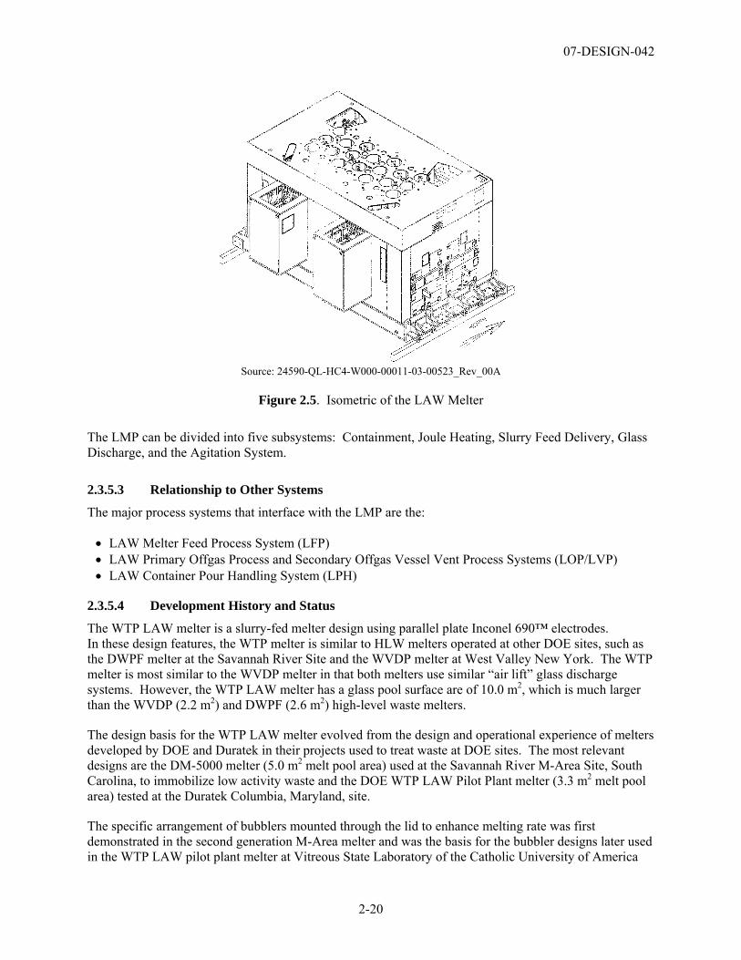
07-DESIGN-042
2-20
Source: 24590-QL-HC4-W000-00011-03-00523_Rev_00A
Figure 2.5. Isometric of the LAW Melter
The LMP can be divided into five subsystems: Containment, Joule Heating, Slurry Feed Delivery, Glass Discharge, and the Agitation System.
2.3.5.3 Relationship to Other Systems
The major process systems that interface with the LMP are the:
• LAW Melter Feed Process System (LFP) • LAW Primary Offgas Process and Secondary Offgas Vessel Vent Process Systems (LOP/LVP) • LAW Container Pour Handling System (LPH)
2.3.5.4 Development History and Status
The WTP LAW melter is a slurry-fed melter design using parallel plate Inconel 690™ electrodes. In these design features, the WTP melter is similar to HLW melters operated at other DOE sites, such as the DWPF melter at the Savannah River Site and the WVDP melter at West Valley New York. The WTP melter is most similar to the WVDP melter in that both melters use similar “air lift” glass discharge systems. However, the WTP LAW melter has a glass pool surface are of 10.0 m2, which is much larger than the WVDP (2.2 m2) and DWPF (2.6 m2) high-level waste melters.
The design basis for the WTP LAW melter evolved from the design and operational experience of melters developed by DOE and Duratek in their projects used to treat waste at DOE sites. The most relevant designs are the DM-5000 melter (5.0 m2 melt pool area) used at the Savannah River M-Area Site, South Carolina, to immobilize low activity waste and the DOE WTP LAW Pilot Plant melter (3.3 m2 melt pool area) tested at the Duratek Columbia, Maryland, site.
The specific arrangement of bubblers mounted through the lid to enhance melting rate was first demonstrated in the second generation M-Area melter and was the basis for the bubbler designs later used in the WTP LAW pilot plant melter at Vitreous State Laboratory of the Catholic University of America
07-DESIGN-042
2-21
(VSL), and the DOE WTP LAW Pilot Plant melter (3.3 m2 melt pool area). One of the most important results of the melter research and development efforts was the demonstration in the Duratek Columbia melter that a significant increase in glass output could be achieved if bubbler tubes were installed in the melter.
Bubblers were tested at the Research and Technology (R&T) subcontractor’s facility, VSL, on the DM1200 melter. Key observations from LAW bubbler testing of Inconel 690 (24590-101-TSA-W000-0009-23-10) include:
• The melter feed material contains significant amounts of chlorides and fluorides. These compounds are known to diffuse into metal where they react to form low-melting point/low-vapor pressure compounds that end up leaving internal voids. These voids can coalesce to form larger voids and weaken the alloy.
• The melter feed material contains significant amounts of sulfur containing compounds. These compounds are known to react with the nickel, chromium, and iron of Inconel 690.
• The melter feed also contains other compounds of nitrates and phosphates. These compounds may contribute to the breakdown of the protective chromium scale and may lead to material corrosion.
• The feed also contains very high levels of sodium as well as potassium, lithium, calcium, and zinc. These materials tend to form molten salts in the cold cap, which can aggressively attack the bubbler support tubes.
Based on these observations, the service life of the bubblers in the LAW melter needed enhancements to meet the LAW performance requirements. A minimum service life of 26 weeks has been specified by the WTP Contractor.
The LAW melter bubbler design uses legs made of MA758 and shin guards made of Inconel 690. The MA758 is the preferred material for the bubbler legs due its resistance to corrosion by the LAW glass; thereby, maximizing the bubbler lifetime and reducing the replacement frequency. The use of Inconel 690 bubbler legs, which have a lower operating life, was considered as a potential means to reduce cost. However, a comparison of the total costs indicated that MA758 and Inconel 690 costs are comparable. Platinum-coated Inconel 690 was also evaluated; it has a lifetime cost less than MA758 but much greater than uncoated Inconel 690.
All of the melters use Monofrax K-3 fused-cast ceramic refractory as the glass contact refractory. The WTP melters also use Monofrax E fused-cast ceramic refractory for the airlift glass discharge riser block for maximum refractory durability in this high-wear area. These melters, excluding the DWPF melter, use an Inconel dam in the wall between the melt pool and the heated glass discharge chambers to prevent glass leakage through this hot wall, and an Inconel trough to transfer the glass through the dam from the airlift riser into the discharge chamber. Water-cooling of the melter based and exterior walls is common to these melters to provide enhanced assurance of glass containment.
The use of the LAW melter containment box, which provides localized shielding, is unique to the WTP. However, this design feature does not require development.
The WTP Research and Technology Program conducted extensive testing of the WTP LAW pilot plant melter to verify design features, glass chemistry, and operating requirements of the WTP LAW melter. A listing of the major technology development summary reports is provided in Appendix D, Table D.6.
07-DESIGN-042
2-22
2.3.5.5 Relevant Environment
The relevant operational environment for the LMP, as identified in the system description (24590-LAW-3YD-LMP-00001), is:
• The system shall melt, contain, and pour molten glass at temperatures up to 1250°C.
• The system shall vitrify wastes with a range of physical properties.
• The discharge chamber shall continuously heat the glass using lid mount heaters to avoid becoming clogged.
• An airlift system shall pour glass into the containers using a bubbler lance immersed in the riser glass.
• The container fill level shall be controlled using an infrared (IR) camera and software for an automatic shutoff.
• Contact maintenance of the LAW melter shall be conducted to periodically replace bubbler assemblies, thermowells, and waste feeding nozzles.
• Installing and replacing a melter system shall be conducted for a melter that weights approximately 200 MT.
2.3.5.6 Comparison of the Relevant Environment and the Demonstrated Environment
The technology for the LAW melter has been demonstrated in a relevant environment. The Duratek LAW pilot melter is essentially a third section version of the full-scale WTP LAW melter, with similar important operational dimensions, such as melt pool depth and width between the opposing electrode bearing walls. The melter is located at the R&T subcontractor’s facility, VSL. The pilot test confirmed the performance and behavior of equipment components and different process flowsheets representative of the WTP mission. Equipment components tested included the melter and its specific design features: melter feed nozzle, melter thermowells, melter bubblers, melter pouring system, and representative instrument and control systems. These testing results showed that the LAW Melter System would support design requirements as specified in the WTP contract (DE-AC27-01RL14136). However, some changes to the full scale melter design will be implemented because of recommendations in the test reports identified in the response to the first question in Table D.7, Appendix D.
The LAW Melter Pilot Plant (approximately 630 days) testing was done in a “locked down” design configuration and with the LAW melter operated similar to the planned plant operation; e.g., operated from a remote control room with no operator intervention/visual cues. Cameras were employed throughout the DM3300 operating life, with some instances of camera outage. Usually images were described as too dark to discern anything. However, the IR camera and selected optics were demonstrated with prototypical full scale containers to 90% fill (24590-101-TSA-W000-0009-101-00007).
2.3.5.7 Technology Readiness Level Determination
The LMP was determined to be TRL 6 because of the extensive development of the melter concept for DOE projects and the extensive development and testing of the LAW Pilot Scale melter for the WTP.
There is uncertainty associated with the ability to reliably manufacture the LAW melter bubbler assemblies. The LAW melter operational concept uses bubblers manufactured from MA758. The WTP Project is experiencing difficulties obtaining qualified MA758 alloy (high chromium alloy) for the LAW bubbler assembly. Production problems on the composition of the alloy were identified in the initial MA758 procurement (CCN: 150410). Recent interactions between the WTP Contractor and Special Metals, the manufacturer of the alloy, indicate that an initial set of bubblers will be fabricated. The two
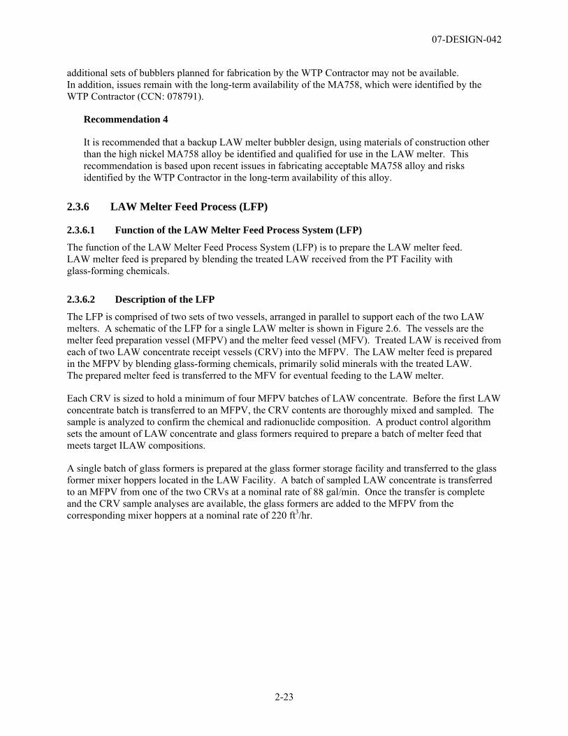
07-DESIGN-042
2-23
additional sets of bubblers planned for fabrication by the WTP Contractor may not be available. In addition, issues remain with the long-term availability of the MA758, which were identified by the WTP Contractor (CCN: 078791).
Recommendation 4
It is recommended that a backup LAW melter bubbler design, using materials of construction other than the high nickel MA758 alloy be identified and qualified for use in the LAW melter. This recommendation is based upon recent issues in fabricating acceptable MA758 alloy and risks identified by the WTP Contractor in the long-term availability of this alloy.
2.3.6 LAW Melter Feed Process (LFP)
2.3.6.1 Function of the LAW Melter Feed Process System (LFP)
The function of the LAW Melter Feed Process System (LFP) is to prepare the LAW melter feed. LAW melter feed is prepared by blending the treated LAW received from the PT Facility with glass-forming chemicals.
2.3.6.2 Description of the LFP
The LFP is comprised of two sets of two vessels, arranged in parallel to support each of the two LAW melters. A schematic of the LFP for a single LAW melter is shown in Figure 2.6. The vessels are the melter feed preparation vessel (MFPV) and the melter feed vessel (MFV). Treated LAW is received from each of two LAW concentrate receipt vessels (CRV) into the MFPV. The LAW melter feed is prepared in the MFPV by blending glass-forming chemicals, primarily solid minerals with the treated LAW. The prepared melter feed is transferred to the MFV for eventual feeding to the LAW melter.
Each CRV is sized to hold a minimum of four MFPV batches of LAW concentrate. Before the first LAW concentrate batch is transferred to an MFPV, the CRV contents are thoroughly mixed and sampled. The sample is analyzed to confirm the chemical and radionuclide composition. A product control algorithm sets the amount of LAW concentrate and glass formers required to prepare a batch of melter feed that meets target ILAW compositions.
A single batch of glass formers is prepared at the glass former storage facility and transferred to the glass former mixer hoppers located in the LAW Facility. A batch of sampled LAW concentrate is transferred to an MFPV from one of the two CRVs at a nominal rate of 88 gal/min. Once the transfer is complete and the CRV sample analyses are available, the glass formers are added to the MFPV from the corresponding mixer hoppers at a nominal rate of 220 ft3/hr.
07-DESIGN-042
2-24
Concentrate Melter feedMelter feed
Melter Feed Vessel (MFV)
Melter FeedPreparation Vessel
(MFPV)
Glass Former Mixer Enclosure
Glass formers
LFP
MelterConcentrate
Receipt Vessel (CRV)
GFR
LFP LMPLFPLCP
Melter feed to other MFPV, or plant wash to Plant Wash Vessel
Concentrate from other CRV, or melter feed from
other MFPV or MFV
Figure 2.6. Process Schematic for LAW Melter Feed Process System (LFP)
The glass former batch may consist of any of the following glass formers: aluminum silicate, boric acid, calcium silicate, ferric oxide, lithium carbonate, magnesium silicate, silica, sodium carbonate, sucrose, titanium dioxide, zinc oxide, zirconium silicate (2459O-LAW-M4C-GFR-000013). The glass formers are mixed with the LAW concentrate using mechanical agitation.
Each MFPV has a melter feed batch capacity of 3,330 gal with a target cycle time of 16 hours (24590-LAW-M4C-20-00002). Batch cycle time will vary from batch to batch depending on the concentration of sodium in the concentrate and the waste loading of the glass. After a specified mixing duration, a batch of melter feed is transferred from the MFPV to the corresponding MFV at a nominal rate of 50 gal/min. The six air displacement slurry (ADS) pumps transfer the slurry from the MFV to the melter at a continuous rate of approximately 1 to 3.2 gal/min to meet the required plant throughput.
The MFPVs are standard designs for mechanically agitated vessels. Each MFPV is equipped with the following:
• Overflow line • Vent line • Sample return line • One mechanical agitator • Two vertical pumps • Two spray nozzles
The MFPVs are constructed of 316 stainless steel, and have an inside diameter of 11 ft, 0 in., and a tangent-to-tangent height of 10 ft, 6 in. with American Society of Mechanical Engineers (ASME) flanged and dished heads. The mechanical agitator continuously mixes the vessel contents to keep insoluble solids in suspension. The time required for uniform blending of each batch is 2 hours (24590-QL-POA-MFAO-00001-10-00001, Test #2). The vertical pump discharges at a maximum flowrate of 50 gal/min through a valve bulge to route the concentrate, melter feed, or plant wash to one of the following: corresponding MFV, other MFPV (for melter shutdown or batch shimming), same MFPV (to recirculate for sampling), or a plant wash vessel for recycle to the PT Facility.
07-DESIGN-042
2-25
The MFVs have a maximum operating volume of 7,689 gallons for receiving blended melter feed from the MFPVs for feed to the corresponding LAW melter. Each MFV is equipped with the following:
• Overflow line • Vent line • Sample return line • One mechanical agitator • Six air displacement slurry (ADS) pumps • One vertical pump • Three spray nozzles
The MFVs are constructed of 316 stainless steel and have an inside diameter of 11 ft, 0 in., and a tangent-to-tangent height of 10 ft, 6 in. with ASME flanged and dished heads. The mechanical agitator continuously mixes the vessel contents to keep insoluble solids in suspension. Each LAW melter is fed with six ADS feed pumps (total) or two ADS feed pumps per each of the three melter zones. Control of the six ADS pumps is coordinated to provide uniform feed delivery and to help maintain and establish melter cold cap integrity. ADS pumps are designed with built-in redundancy. The melter is designed to allow one feed nozzle/ADS pump combination per melter zone to be inoperable.
2.3.6.3 Relationship to Other Systems
The primary interfacing systems for the LFP are the:
• Autosampling System (ASX), which receives waste samples from MFPVs and MFVs. • Glass Formers Reagent System (GFR), which supplies glass formers to MFPVs. • LAW Concentrate Receipt Process System (LCP), which supplies LAW concentrate to MFPVs. • LAW Melter Process System (LMP), which immobilized waste feed slurry produced in the LFP.
None of these interfacing systems adds a new technology to the LFP.
2.3.6.4 Development History and Status
Extensive testing of the LAW melter feed system at the R&T subcontractor’s facility, VSL, has provided the primary basis for the design of the LFP (24590-101-TSA-W000-0009-171-00001). Based on LAW pilot melter experience, the potential for solids collecting on the tank wall at the wetted liquid line was identified. As a result, water spray capabilities and acid wash/soak capabilities were maintained or added to the tank designs. Specific testing was also completed by the R&T testing at SCTC of the mixing system (SCT-M0SRLE60-00-187-02, Rev. 00B; -187-02 Rev. 00C [cleared]) to test blending of glass-forming chemicals and simulated wastes. Testing performed at the Savannah River Technology Center (SRTC) indicate the glass-forming chemicals deposit on a liquid surface and are drawn below the surface; therefore, the MFPV mechanical agitator design required sufficient surface mixing (i.e., create a vortex at the shaft) to incorporate glass-forming chemicals into the waste slurry.
Testing of the proposed plant scale system was completed by Philadelphia Mixer to verify design performance. The mixing report from the vendor demonstrates the adequacy of the system design (24590-QL-POA-MFAO-00001-10-00001). Additional testing is planned as part of the R&T Program to test homogeneity of mixed simulated waste and melter feed mixtures, as well as the ASX (VSL-06T1000-1). The purpose of this testing is to further characterize the homogeneity of waste by use of the mixing system to provide a basis for establishing the number of samples to obtain from the MFPV to support LAW Facility operations.
07-DESIGN-042
2-26
2.3.6.5 Relevant Environment
The operating environment for the LFP is specified in the WTP Basis of Design (24590-WTP-DB-ENG-01-001), the LFP system description (24590-LAW-3YD-LFP-00001), and the LAW PSAR (24590-WTP-PSAR-ESH-01-002-03). The relevant operational environment for the LFP is the:
• Remote operation of process fluid mixing equipment to prevent the release of radioactive liquids and solid materials
• Mixing of high solids slurries (approximately 50 wt% solids) that have high viscosities and shear strength
• Transfer of high solids slurries.
2.3.6.6 Comparison of the Relevant Environment and the Demonstrated Environment
The LFP was demonstrated in a relevant environment at SRTC and VSL. Summary reports describe the properties of feeds used for testing (SCT-M0SRLE60-00-193-02; 24590-101-TSA-W000-0009-172-00001; 24590-101-TSA-W000-0009-152-00001). The mixing system design was provided by the vendor. The vendor conducted testing of the agitation system based upon vessel design and mixing requirements. The mixing report from the vendor demonstrates the adequacy of the system design (24590-QL-POA-MFAO-00001-10-00001). Additional testing is planned as part of the R&T Program to test the homogeneity of mixed simulated waste and sampling systems. In addition, the test reports identified in the response to the first question in Table D.6 of Appendix D, for the LAW melter feed process provide additional data on the performance of the system for mixing of simulated wastes.
2.3.6.7 Technology Readiness Level Determination
The LFP was determined to be TRL 6 because of the previous use of the waste and glass former mixing technology on other DOE projects (WVDP and DWPF), at VSL and SRTC, and the WTP Project-specific testing completed by Philadelphia Mixers (24590-QL-POA-MFAO-00001-10-00001) that provided the specification for the mechanical agitators for the plant scale system.
2.3.7 LAW Primary Offgas Process and Secondary Offgas Vessel Vent Process Systems (LOP/LVP)
2.3.7.1 Function of the LAW Primary Offgas Process and Secondary Offgas Vessel Vent Process Systems (LOP/LVP)
The function of the LAW Primary Offgas Process System (LOP) is to cool the offgas and remove aerosols generated by the LAW melters. The purpose of the LAW Secondary Offgas Vessel Vent Process System (LVP) is to remove almost all remaining particulates, miscellaneous acid gases, nitrogen oxides, volatile organic compounds (VOC), and mercury from the combined primary offgas and vessel vent streams.
2.3.7.2 Description of the LFP
The LOP and LVP are described in LOP/LVP system description (24590-LAW-3YD-LOP-00001). These systems are designed to treat the LAW melter offgas so that it conforms to relevant federal, state, and local air emissions requirements at the point of discharge from the facility stack. The principal gas generated by the melter is steam. Decomposition of salts and organic material also yields carbon dioxide (CO2), sulfur dioxide (SO2), nitrogen oxide (NOx), hydrogen chloride (HCl), and hydrogen fluoride (HF).
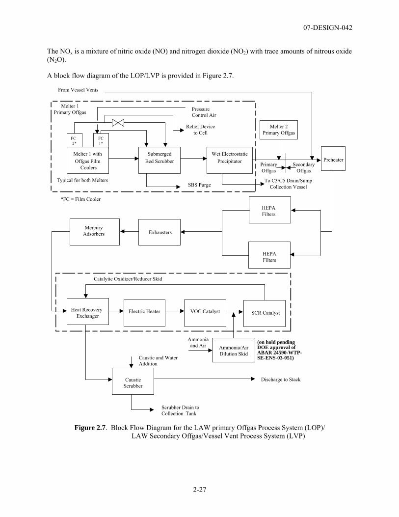
07-DESIGN-042
2-27
The NOx is a mixture of nitric oxide (NO) and nitrogen dioxide (NO2) with trace amounts of nitrous oxide (N2O).
A block flow diagram of the LOP/LVP is provided in Figure 2.7.
SecondaryOffgas
PrimaryOffgas
Catalytic Oxidizer/Reducer Skid
Typical for both Melters
Preheater
HEPAFilters
HEPAFilters
Exhausters
Heat RecoveryExchanger
Electric Heater VOC Catalyst SCR Catalyst
Discharge to Stack
From Vessel Vents
*FC = Film Cooler
Ammoniaand Air
FC2*
FC1*
Melter 1 withOffgas Film
Coolers
SubmergedBed Scrubber
Caustic and WaterAddition
Scrubber Drain toCollection Tank
SBS Purge
PressureControl Air
Wet ElectrostaticPrecipitator
To C3/C5 Drain/SumpCollection Vessel
Relief Deviceto Cell
CausticScrubber
Melter 2Primary Offgas
MercuryAdsorbers
Melter 1Primary Offgas
Ammonia/AirDilution Skid
(on hold pendingDOE approval ofABAR 24590-WTP-SE-ENS-03-051)
Figure 2.7. Block Flow Diagram for the LAW primary Offgas Process System (LOP)/
LAW Secondary Offgas/Vessel Vent Process System (LVP)
07-DESIGN-042
2-28
The LOP consists of the following major components for each melter:
• Offgas film coolers: When a cold cap is present in the melter, the offgas exits the melter at approximately 750°F and mixes with injection air in a primary offgas film cooler. The primary offgas film cooler cools the offgas below the glass-sticking temperature to minimize solids deposition on the offgas piping walls. This film cooler is a double-walled pipe designed to introduce air along the walls through a series of holes or slots in the inner wall. The injection air that flows along the pipe wall mixes with, and cools, the offgas to approximately 600°F.
• Submerged bed scrubbers (SBS): Offgas from the film coolers enters a packed bed column submerged in water for further cooling. Each melter has a dedicated SBS. The SBS column has a diameter of 6 ft, 2 in., and a packed bed height of 24 in. The SBS is 6.5 ft high (tangent to tangent) by 10 ft in diameter with a maximum operating volume of 3,690 gal. The SBS is a passive device designed for steam quenching, scrubbing of entrained particulates and partial removal of aerosols from melter offgas.
• Wet electrostatic precipitators (WESP): After the initial SBS, the cooled offgas is routed to a WESP for further removal of particulates and aerosols. Each melter system has a dedicated WESP. The WESP receives offgas at a nominal flowrate of 1,280 scfm at 122OF and -49 in. WG. The design flow is 2,000 scfm based on the combined offgas from two idled melters. The WESP body, exclusive of electrode ducts, is 8 ft in diameter by 21.5 ft high (overall). The offgas enters the unit and passes through a distribution plate. The evenly distributed saturated gas then flows upward through the tubes of the WESP. The tubes act as positive electrodes. Each tube also has a single negatively charged electrode that runs down the center of the tube. A high-voltage transformer rectifier supplies the power to these electrodes. A strong electric field is generated along the electrode, supplying a negative charge to aerosols as they pass through the tubes. The negatively charged aerosols move toward the positively charged tube walls where they are removed. The inlet is also provided with a spray to enhance rundown and cleaning. The condensate then drains into a sump collection vessel. A deluge system is also provided at the top of the tube section for periodic washing as necessary to maintain performance.
The LVP system consists of the following major components:
• High-efficiency particulate air (HEPA) filters and preheaters: HEPA filters provide the final removal of radioactive particulates to protect downstream equipment from contamination. The combined offgas stream is passed through a preheater. The electric heaters increase the nominal gas temperature from 131°F to 149°F to avoid condensation in the HEPA filters. The heated offgas passes through HEPA filter housings forming two trains: a main train used in normal operations and an auxiliary train used as an installed backup. The HEPA filter housings in each train are arranged to form primary and secondary stages of filtration.
• Exhausters: Three multi-stage centrifugal blowers with adjustable speed drives are located downstream of the HEPA filters to provide vacuum to maintain the LOP system flow. Each exhauster is rated at 50% of the system capacity. Two exhausters will normally be running at a time with the third exhauster in standby.
• Mercury adsorbers: Activated carbon is used to remove mercury and acid gases. The offgas flows to two mercury adsorbers that are normally operated in series as part of a mercury mitigation equipment skid. Each adsorber is approximately 8 ft high by 11 ft wide by 26 ft long with an activated carbon bed volume of about 223 ft3. The unit is designed to obtain a removal efficiency of greater than 97% for hydrochloric or hydrofluoric acid, and greater than 99% for iodine. The mercury concentration in
07-DESIGN-042
2-29
the offgas is reduced to a maximum of 45 pg/dscm, and the outlet concentration is measured with a continuous emission monitor.
• Catalytic oxidizer/reducer: The offgas has high levels of NOx because the melter decomposes the parent nitrate/nitrite compounds. Some of the resultant NOx is decomposed to nitrogen and water in the melter, and some is removed by scrubbing in the SBS. VOCs are also present in the offgas stream. Both the VOCs and the remaining NOx require removal. The offgas is passed through a catalytic oxidizer-reducer skid housing a heat recovery exchanger, an electric heater, VOC catalyst, and selective catalytic reduction (SCR) catalyst. Approximate dimensions for the skid are 36 ft long by 11 ft high by 8 ft wide, with a nominal inlet flowrate of 4,180 scfm at 216°F and 28 in. WG.
The heated offgas is passed through the VOC catalyst to oxidize VOCs and carbon monoxide (CO) to carbon dioxide (CO2) and water vapor. The VOC catalyst is a platinum-based material deposited on a metal monolith, which is held in frames, inserted, and removed through access doors.
The offgas is then injected with a mixture of ammonia vapor and air. Following ammonia injection, the offgas is passed through the SCR catalyst to reduce NOx to nitrogen and water vapor. The SCR catalyst is a titanium oxide-based material deposited on a metal monolith, which is held in frames and inserted/removed through access doors. The SCR catalyst is designed to achieve a NO, reduction of 98%.
• Caustic scrubber: A caustic scrubber further treats the offgas by removing acid gases (i.e., 97% removal efficiency for combined sulfur dioxide [SO2] and sulfur trioxide [SO3]), and providing cooling before discharge into the LAW Facility stack.
2.3.7.3 Relationship to other Systems
The primary interface with the LOP/LVP is the LAW Melter Process System (LMP). Primary and standby offgas film coolers receive LMP offgas. Other interfaces are with waste treatment systems. Condensate from the SBS water purge pumps, SBS condensate purge pumps, and WESPs are discharged to the Radioactive Liquid Waste Disposal System (RLD). Waste is discharged from the caustic collection tank to outside the PT facility. Solid wastes from the SBS, SBS condensate vessels, and WESPs are sent to Radioactive Solid Waste Handling System (RWH).
2.3.7.4 Development History and Status
The design of the LOP/LVP is based upon the use of most of these equipment systems for DOE’s WVDP. The WVDP used a liquid-fed ceramic melter to vitrify actual radioactive tank wastes.
In addition, as part of the WTP development melter testing using the DM-1200 melter, a prototypically designed engineering scale melter, the offgas system was tested and evaluated. This testing evaluated the impact due to compositional variations of the simulated waste feeds and included testing to support regulatory permit requirements. Responses to specific questions in Appendix D, Table D.7 summarize the experimental testing reports for the engineering scale offgas system.
One of the WTP dangerous waste permit conditions requires the HLW and LAW Facilities melter and melter offgas systems meet the 4-9s destruction and removal efficiency (DRE) performance standard for principal organic dangerous constituents (PODC). Based on agreement between the WTP, the U.S. Environmental Protection Agency, and the Washington State Department of Ecology, the PODCs selected to demonstrate DRE are naphthalene and allyl alcohol (CCN: 080128).
Prior to conducting the DRE tests, the DM1200 offgas system was modified to more closely represent the WTP process configuration. These modifications included the addition of a full-flow activated carbon
07-DESIGN-042
2-30
adsorber bed and change of the thermal catalytic oxidizer catalyst media to match the WTP design. DRE tests were performed at the R&T subcontractor’s facility, VSL, on the DM1200 from November 2004 through March 2005. The VSL DM1200 test results (VSL-05R5830-1) exceeded 4-9s DRE in all 12 allyl alcohol test runs and in 10 out of the 12 naphthalene test runs. The objective of at least 4-9s DRE was achieved for all test runs, except for two sampling periods, which had 99.987 and 99.978 % DRE for HLW and LAW, respectively. The naphthalene emission rate required to demonstrate 4-9s DRE in the VSL testing was 0.09 mg/min. The naphthalene emission rates for the failed runs were 0.11 and 0.2 mg/min for HLW and LAW, respectively. The passing runs had naphthalene emission rates that ranged from 0.02 to less than 0.002 mg/min.
The WTP Project has evaluated the impact of not achieving the DRE test requirements on the WTP design (CCN: 128559; 24590-WTP-RPT-ENV-03-00005) and has concluded that the actual WTP offgas system design is more robust compared to the DM-1200 offgas system. Based upon analysis, sufficient design contingency exists in the WTP design, and it is projected that the LAW Facility will achieve the DRE requirements in normal and challenge conditions.
The WTP Project has a risk item associated with the ability of LAW Facility to meet the DRE test requirements. This risk will remain open until actual testing of the LAW Facility is completed during cold commissioning.
2.3.7.5 Relevant Environment
The operating environment for the LOP/LVP is specified in the WTP Basis of Design (24590-WTP-DB-ENG-01-001) and the LOP/LVP system description (24590-LAW-3YD-LOP-00001). The relevant environment for the LOP/LVP is the:
• Operation of equipment system with high reliability
• Operation of the offgas system with high initial temperatures, high moisture levels and significant particulate loads, and the presence of corrosive acid gasses
• Use of fixed bed catalyst and absorber beds in the presence of trace poisoning agents
• Operation of the equipment system at a reduce pressure compared to atmospheric.
2.3.7.6 Comparison of the Relevant Environment and the Demonstrated Environment
The system was demonstrated in a relevant environment. The R&T was completed on a prototype LOP/LVP connected to the DM1200 melter, which is a one-eighth scale of the LAW Vitrification Facility offgas system. Equipment components tested included all prototypical offgas components (i.e., film cooler, SBS, high efficiency mist eliminator, WESP, sulfur-impregnated activated carbon bed for mercury removal, and the catalytic oxidizer/reducer for organic destruction and NOx reduction, HEPA filtration, and a caustic scrubber). These testing results showed that the LOP/LVP will support design requirements as specified in the WTP contract.
2.3.7.7 Technology Readiness Level Determination
The LOP/LVP was determined to be a TRL 6 because of the previous demonstrated use of the offgas treatment components in the WVDP, and the extensive testing that was completed as part of the DM-1200 melter testing for the WTP. Issues associated with the offgas system not achieving the DRE test requirements have been evaluated and will be confirmed during cold commissioning of the LAW Facility.

07-DESIGN-042
2-31
Throughout DM1200 SBS testing at VSL (VSL-06R6410-2), the SBS was periodically drained and inspected for deposits and unusual wear. The most significant findings were accumulations of deposits in the downcommer and bottom of the SBS, the accumulation. VSL conducted tests of the WESP (24590-101-TSA-W000-0009-174-0000) that showed the decontamination factor (DF) degraded as a result of solids buildup on the electrode. Flushing the solids from the VSL WESP effectively removed the solids buildup, but resulted in the shorting of the electrical connections because the top insulators did not drain.

07-DESIGN-042
3-1
3.0 Summary and Recommendations
3.1 Summary The TRA for the LAB, BOF, and LAW facilities determined that:
• Two LAB systems were determined to be CTEs and were evaluated; the ASX, and the LA-ICP-AES and LA-ICP-MS in the AHL, which provide the analytical equipment systems for the LAB.
• No BOF systems were judged to be CTEs because the BOF systems do not use new technologies, or use standard technologies in new or novel ways,
• Five LAW systems were determined to be CTEs: the LAW Melter Feed Process System (LFP) used to prepare the LAW melter feed, the LAW Melter System (LMP), which includes the LAW melter, the LAW Melter Offgas System/LAW Secondary Offgas/Vessel Vent Process Systems (LOP/LVP) used to treat the LAW melter offgas, the ILAW Container Finishing Handling System (LFH ) container closure subsystem and the ILAW LFH container decontamination subsystem.
The results of the TRL assessment are summarized in Table 3.1. Consistent with NASA and DoD practice, this assessment used TRL 6 as the level that should be attained before the technology is incorporated in the WTP final design. The CTEs were not evaluated to determine if they had matured beyond level 6.
3.2 Recommendations The Assessment Team concluded that the critical technology elements of the LAB, BOF, and LAW facilities are sufficiently mature to continue to advance the final design of these facilities. However, based upon the results of this assessment, the following recommendations for specific technologies are made:
1. The prototypical LA-ICP-AES system should be tested to demonstrate achievable detection limits for chemical elements of interest, and to satisfy turnaround time requirements on actual HLW sludge samples in a relevant environment to support the final design of the actual LAB subsystems. The LA-ICP-MS can be qualified in the AHL after laser ablation technology has been implemented with ICP-AES in the AHL and is fully operational.
Testing is recommended to confirm that the development and design of the LA-ICP-AES will meet its functional requirements. Design optimization for AHL implementation should continue following demonstration of the prototype. This testing is included in the WTP baseline.
2. Integrated prototypic testing of the actual immobilized low-activity waste (ILAW) container inert filling, flange cleaning, inspection, and lidding/delidding equipment system in a simulated remote environment should be completed prior to installation in the LAW Vitrification Facility to verify that the equipment system will perform as required.
The mechanical processing steps of the container lidding sealing system used to seal the containers uses new equipment concepts that have not been previously tested in a remote operational environment. Waiting to complete the testing at cold commissioning represents a significant cost and schedule risk to the LAW Facility if the technology does not perform as intended. Fabrication acceptance testing is planned; however, this testing will not be prototypical of the remote operational environment. The testing should validate the adequacy of the design concept prior to completing detailed design.
07-DESIGN-042
3-2
3. Integrated prototypic testing of the actual ILAW container decontamination and smear testing systems in a simulated remote environment should be completed following fabrication of equipment components to verify the equipment system will perform as required, and will achieve the WTP Project-specified surface decontamination levels (less than 100 dpm/100 cm2 alpha and less than 1,000 dpm/100cm2 beta-gamma). This testing program should be supplemented with laboratory scale testing to define the operational parameters for the carbon dioxide (CO2) decontamination system.
The ILAW container decontamination subsystem relies on a localized surface decontamination approach using a CO2 pellet spray contained within a series of specialized shrouds. A robot is used to position the shrouds against the surfaces of the ILAW container. A vacuum is used to recover loosened contamination and sublimed CO2. Proof of concept testing using flat-metal coupons was completed. However, there remains a high risk that the removal of the contamination from the container oxide film will not be effective due to the complex shapes on the container design and the requirement that the shroud system effectively contain loosened contamination. A loss of control of the removed contamination in the areas adjacent to the container decontamination station may result in re-contamination of the container. Subsequent decontamination of the work area may also result in impacts to the LAW Facility production schedule.
Based upon the limited testing completed and the unique operating requirements for this system, there is a high probability that the current design concept may not perform as intended and will require significant design changes. Problems with this system may not be identified until hot commissioning of the LAW Facility. Design modifications at this time will be expensive and time-consuming. An inability of the CO2 decontamination system to perform its function has the potential to shut down LAW processing and the entire WTP.
The testing of the ILAW container decontamination subsystem should include testing with full scale containers at the anticipated operating temperatures. Particular attention in the testing program should be focused on the use of the localized decontamination shroud system and its ability to maintain contamination control and achieve full decontamination of the container. The ability of the shroud tools to decontaminate all container surfaces should be demonstrated.
4. It is recommended that a backup LAW melter bubbler design, using materials of construction other than the high nickel MA758 alloy be identified and qualified for use in the LAW melter. This recommendation is based upon recent issues in fabricating acceptable MA758 alloy and risks identified by the WTP Contractor in the long-term availability of this alloy.
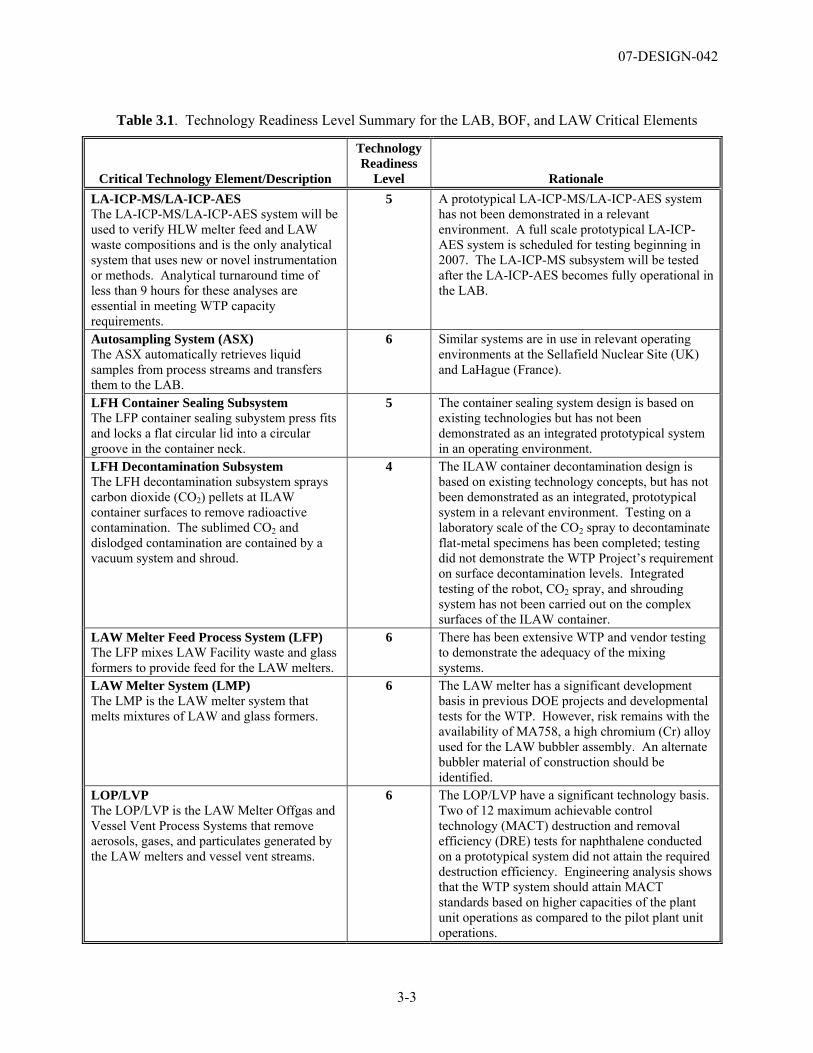
07-DESIGN-042
3-3
Table 3.1. Technology Readiness Level Summary for the LAB, BOF, and LAW Critical Elements
Critical Technology Element/Description
Technology Readiness
Level Rationale LA-ICP-MS/LA-ICP-AES The LA-ICP-MS/LA-ICP-AES system will be used to verify HLW melter feed and LAW waste compositions and is the only analytical system that uses new or novel instrumentation or methods. Analytical turnaround time of less than 9 hours for these analyses are essential in meeting WTP capacity requirements.
5 A prototypical LA-ICP-MS/LA-ICP-AES system has not been demonstrated in a relevant environment. A full scale prototypical LA-ICP-AES system is scheduled for testing beginning in 2007. The LA-ICP-MS subsystem will be tested after the LA-ICP-AES becomes fully operational in the LAB.
Autosampling System (ASX) The ASX automatically retrieves liquid samples from process streams and transfers them to the LAB.
6 Similar systems are in use in relevant operating environments at the Sellafield Nuclear Site (UK) and LaHague (France).
LFH Container Sealing Subsystem The LFP container sealing subystem press fits and locks a flat circular lid into a circular groove in the container neck.
5 The container sealing system design is based on existing technologies but has not been demonstrated as an integrated prototypical system in an operating environment.
LFH Decontamination Subsystem The LFH decontamination subsystem sprays carbon dioxide (CO2) pellets at ILAW container surfaces to remove radioactive contamination. The sublimed CO2 and dislodged contamination are contained by a vacuum system and shroud.
4 The ILAW container decontamination design is based on existing technology concepts, but has not been demonstrated as an integrated, prototypical system in a relevant environment. Testing on a laboratory scale of the CO2 spray to decontaminate flat-metal specimens has been completed; testing did not demonstrate the WTP Project’s requirement on surface decontamination levels. Integrated testing of the robot, CO2 spray, and shrouding system has not been carried out on the complex surfaces of the ILAW container.
LAW Melter Feed Process System (LFP) The LFP mixes LAW Facility waste and glass formers to provide feed for the LAW melters.
6 There has been extensive WTP and vendor testing to demonstrate the adequacy of the mixing systems.
LAW Melter System (LMP) The LMP is the LAW melter system that melts mixtures of LAW and glass formers.
6 The LAW melter has a significant development basis in previous DOE projects and developmental tests for the WTP. However, risk remains with the availability of MA758, a high chromium (Cr) alloy used for the LAW bubbler assembly. An alternate bubbler material of construction should be identified.
LOP/LVP The LOP/LVP is the LAW Melter Offgas and Vessel Vent Process Systems that remove aerosols, gases, and particulates generated by the LAW melters and vessel vent streams.
6 The LOP/LVP have a significant technology basis. Two of 12 maximum achievable control technology (MACT) destruction and removal efficiency (DRE) tests for naphthalene conducted on a prototypical system did not attain the required destruction efficiency. Engineering analysis shows that the WTP system should attain MACT standards based on higher capacities of the plant unit operations as compared to the pilot plant unit operations.

07-DESIGN-042
4-1
4.0 References
1. 06-WTP-105, “Transmittal of U.S. Department of Energy, Office of River Protection (ORP) Design Oversight Report Number D-06-DESIGN-027: Review of Bechtel National, Inc.’s (BNI) Radiochemical Analytical Laboratory Pneumatic Autosampling System (ASX) Design,” letter dated September 25, 2006, U.S. Department of Energy, Richland, Washington.
2. 24590-101-TSA-W000-0004-158-00002, Rev. A, Laser Ablation Study for High Level Waste and Melter Feed Characterization, March 9, 2006, Bechtel National, Inc., Richland, Washington.
3. 24590-101-TSA-W000-0009-101-00007, Rev. 00A, RPP-WTP Pilot Melter Prototypic LAW Container and HLW Canister Glass Fill Test Results Report, May 26, 2004, Bechtel National, Inc., Richland, Washington.
4. 24590-101-TSA-W000-0009-101-00007, Rev. 00A, “Prototypic LAW Container and HLW Canister Glass Fill Test Results Report,” April 27, 2004, Bechtel National, Inc., Richland, Washington.
5. 24590-101-TSA-W000-0009-152-00001, Rev. 00A, Characterization of Simulated WTP LAW Melter Feeds, June 24, 2004, Bechtel National, Inc., Richland, Washington.
6. 24590-101-TSA-W000-0009-171-00001 Rev. 00A, Summary of DM1200 Operation at VSL, October 10, 2006, Bechtel National, Inc., Richland, Washington.
7. 24590-101-TSA-W000-0009-172-00001 Rev. 00A, Review of Properties of Simulated Feeds Used for Melter Testing, August 26, 2006, Bechtel National, Inc., Richland, Washington.
8. 24590-101-TSA-W000-0009-174-00001 Rev. 00A, Summary of DM1200 WESP History and Performance, August 7, 2006, Bechtel National, Inc., Richland, Washington.
9. 24590-101-TSA-W000-0009-23-10, Rev. 00C, RPP-WTP Pilot Melter Bubbler Life Extension Test Results Report, January 7, 2004, Bechtel National, Inc., Richland, Washington.
10. 24590-HLW-RPT-RT-05-001, Rev. 0, Preliminary IHLW Formulation Algorithm Description, River Protection Project, 2006, Bechtel National, Inc., Richland, Washington.
11. 24590-LAB-3YD-AHL-00001, Rev. 1, System Description for the Analytical Hot Cell Laboratory Equipment (AHL), August 5, 2005, Bechtel National, Inc., Richland, Washington.
12. 24590-LAB-3YD-ARL-00001, Rev. 1, System Description for the Analytical Radiological Laboratory Equipment (ARL), February 3, 2005, Bechtel National, Inc., Richland, Washington.
13. 24590-LAW-3PS-HCTH-T0001, Engineering Specification for the LAW Product Container Lidding Equipment, February 16, 2006, Bechtel National, Inc., Richland, Washington.
14. 24590-LAW-3PS-HDYR-T0001, Engineering Specification for the Power Manipulators and Turntables, July 11, 2005, Bechtel National, Inc., Richland, Washington.
15. 24590-LAW-3YD-LFH-00001, Rev. 0, System Description for the System LFH-LAW Container Finishing Handling System, October 13, 2006, Bechtel National, Inc., Richland, Washington.
07-DESIGN-042
4-2
16. 24590-LAW-3YD-LFH-00001, Rev. 0, System Description for the System LFH-LAW Container Finishing Handling System, October 13, 2006, Bechtel National, Inc., Richland, Washington.
17. 24590-LAW-3YD-LFP-00001, Rev. 0, System Description for the LAW Melter Feed Process (LFP) System, June 24, 2005, Bechtel National, Inc., Richland, Washington.
18. 24590-LAW-3YD-LMP-00001, Rev. 0, System Description for the LAW Melter Process System (LMP), November 9, 2006, Bechtel National, Inc., Richland, Washington.
19. 24590-LAW-3YD-LOP-00001, Rev. 1, System Description for the LAW Primary Offgas Process (LOP) and LAW Secondary Offgas/Vessel Vent Process (LVP) Systems, March 23, 2005, Bechtel National, Inc., Richland, Washington.
20. 24590-LAW-M4C-20-00002, LAW LCP and LFP Batch Volumes, December 30, 2003, Bechtel National Inc., Richland, Washington.
21. 24590-LAW-M4C-GFR-00001, LAW Blended Glass Former Average Densities, November 21, 2005, Bechtel National Inc., Richland, Washington.
22. 24590-LAW-RPT-RT-04-0003, Rev. 0, Preliminary ILAW Formulation Algorithm Description, May 18, 2005, Bechtel National, Inc., Richland, Washington.
23. 24590-QL-HC4-HAHH-00001-05-00002, ISOLOCK Sampler Device Component Performance Test Report, April 1, 2005, Bechtel National, Inc., Richland, Washington.
24. 24590-QL-POA-MFAO-00001-10-00001, Rev. 00B, Rotating Mechanical Agitators Test Report, prepared by Philadelphia Mixers for Bechtel National Corp., March 17, 2004, Bechtel National, Inc., Richland, Washington.
25. 24590-WTP-3PS-MHSS-T0002, Rev. 0, Engineering Specification for Autosampling System (ASX), June 16, 2004, Bechtel National, Inc., Richland, Washington.
26. 24590-WTP-3YD-ASX-00001 Rev. A, System Description for the Autosampling System (ASX), April 2002. Bechtel National Inc., Richland, Washington.
27. 24590-WTP-DB-ENG-01-001, Rev. 1C, WTP Basis of Design, November 2006, Bechtel National, Inc., Richland, Washington.
28. 24590-WTP-PL-PR-04-0001, Rev. 0, Integrated Sampling and Analysis Requirements Document, December 8, 2004, Bechtel National, Inc., Richland, Washington.
29. 24590-WTP-PL-RT-03-002, Rev. 2, IHLW Product Compliance Plan, 2005, Bechtel National, Inc., Richland, Washington.
30. 24590-WTP-PSAR-ESH-01-002-03, Rev. 1, Preliminary Safety Analysis Report to Support Construction Authorization; LAW Facility Specific Information, September 30, 2003, Bechtel National, Inc., Richland, Washington.
31. 24590-WTP-RPT-ENV-03-00005, Rev. 0, Report, 4-9s Destruction and Removal Efficiency Assessment, November 20, 2003, Bechtel National, Inc., Richland, Washington.
07-DESIGN-042
4-3
32. 24950-WTP-RPT-OP-06-001, Rev. 0., LA-ICP Analysis Method for Hanford Vitrification Process, August 2006, Bechtel National, Inc., Richland, Washington.
33. CCN: 132846, “Report of External Flowsheet Review Team for the Hanford Waste Treatment and Immobilization Plant-Final Report Titled: “Comprehensive Review of the Hanford Waste Treatment Plant Flowsheet and Throughput,” letter dated March 17, 2006, Bechtel National Inc., Richland, Washington.
34. CCN: 139427, “Waste Treatment and Immobilization Plant/222-S Laser Ablation Test Plan,” letter dated May 16, 2006, Bechtel National, Inc., Richland, Washington.
35. CCN: 133570, “Concurrence of ASX Risks and Risk Mitigation Strategy,” letter dated March 9, 2006, Bechtel National, Inc., Richland, Washington.
36. CCN: 150410, “LAW Melter Bubbler Materials,” letter dated January 23, 2007, Bechtel National, Inc., Richland, Washington.
37. CCN: 078791, “Consideration on Melter Materials,” letter dated February 24, 2005, Bechtel National, Inc., Richland, Washington.
38. CCN: 080128, Letter, from R. J. Schepens, DOE ORP, to M. A. Wilson, Washington State Department of Ecology, “Request for Concurrence with Principal Organic Dangerous Constituents (PODCs) for Demonstrating a 99.99 Percent Organic Destruction and Removal Efficiency (DRE),” 03-AMWTP-164, dated December 17, 2003.
39. CCN: 128559, “White Paper on the Analysis of Naphthalene Destruction and Removal Efficiency (DRE) Testing at the Vitreous State Laboratory (VSL),” letter dated December 15, 2005, Bechtel National, Inc., Richland, Washington.
40. CCN:146465, “Laser Ablation-Inductively Coupled Plasma-Atomic Emission Spectroscopy Method Development Summary,” letter dated October 30, 2006, Bechtel National, Inc., Richland, Washington
41. DOD 2005, Department of Defense, Technology Readiness Assessment (TRA) Deskbook, May 2005, Prepared by the Deputy Undersecretary of Defense for Science and Technology (DUSD(S&T)).
42. DODI 5000.2, Acquisition System Guidebook, November 2004, Department of Defense.
43. DOE 2006, Memorandum from Paul Bosco to James A. Rispoli, “Performance Baseline Validation and Transmittal of the External Independent Review Reports for the Waste Treatment and Immobilization Plant Project at Richland Washington,” December 16, 2006, U.S. Department of Energy, Washington D.C.
44. GAO/NSIAD-99-162, Best Practices: Better Management of Technology Can Improve Weapon System Outcomes, July 1999, United States General Accounting Office.
45. NHC-8373, The Interlaboratory Pneumatic Transfer Network for Radioactive Samples Operated in the Analytical Laboratories of the COGEMA La Hague Reprocessing Plants (France), June 2001, Numatec Hanford Company, Richland, Washington.
07-DESIGN-042
4-4
46. NHC-8374, The Computerized Data Management System Operated in the Analytical Laboratories of the COGEMA La Hague Reprocessing Plants (France), June 2001, Numatec Hanford Company, Richland, Washington.
47. NHC-8375, Analysis Operating Times Observed in the Analytical Laboratories of the COGEMA La Hague Reprocessing Plants (France), June 2001, Numatec Hanford Company, Richland, Washington.
48. Nolte, William L., et al., “Technology Readiness Level Calculator,” October 20, 2003, Air Force Research Laboratory, presented at the NDIA Systems Engineering Conference.
49. SCT-M0SRLE60-00-110-12, Rev. 0, LAW Radioactive Coupon CO2 Decontamination Test, May 2003, Savannah River Technology Center, Aiken, South Carolina.
50. SCT-M0SRLE60-00-193-02, Rev. 00A, Development of Simulants to Support Mixing Tests for High Level Waste and Low Activity Waste, December 13, 2003, Savannah River Technology Center, Aiken, South Carolina.
51. SCT-M0SRLE60-00-99-07, LAW Vendor Coupon CO2 Blasting Tests, June 2002, Savannah River Technology Center, Aiken, South Carolina.
52. SCT-MOSRLE60-00-216-00001, Rev. 00A; The Development of Laser Ablation Inductively Coupled Plasma Atomic Emission Spectroscopy for the Analysis of Hanford High Level Waste: Phase I (U), September 27, 2005, Bechtel National, Inc., Richland, Washington
53. SCT-MOSRLE60-00-216-00002, Rev. 00A, The Development of Laser Ablation Inductively Coupled Plasma Atomic Emission Spectroscopy for the Analysis of Hanford High Level Waste: Phase II (U), March 9, 2006, Bechtel National, Inc., Richland, Washington.
54. TN-24590-02-00665, Mechanical Sealing of ILAW Container, October 22, 2002, Bechtel National, Inc. Richland, Washington.
55. VSL-05R5830-1, Revision 0, Regulatory Offgas Emissions Testing on the DM1200 Melter System Using HLW and LAW Simulants, October 31, 2005, Vitreous State Laboratory, Washington D.C.
56. VSL-06R6410-2 Rev. 0, Summary of DM1200 SBS History and Performance, October 10, 2006, Vitreous State Laboratory, The Catholic University of America, Washington D.C.
57. VSL-06T1000-1, Test Plan; Pretreated Waste and Melter Feed Composition Variability Testing Using HLW and LAW Simulants, September 29, 2006, Vitreous State Laboratory, The Catholic University of America, Washington D.C.
58. WTP-RPT- 139, Conventional Non-Dilute West Chemistry Dissolution ICP-AES Time Study, M. W. Urie, B. M. Oliver, and C. Z. Soderquist, 2005, Battelle-Pacific Northwest Division (PNWD), Richland, Washington (proprietary).
59. WTP-RPT-140, Laser Abation CP-AES Time Study, S. K. Fiskum, M. L. Alexander, O. T. Farmer III, M. P. Thomas, and M. W. Urie, 2005, Battelle-Pacific Northwest Division (PNWD), Richland, Washington (proprietary).
07-DESIGN-042
Appendix A
Technology Readiness Level Development and Definitions

07-DESIGN-042
A-1
Appendix A Technology Readiness Level Development and Definitions
A.1 TRL Development Technology Readiness Levels (TRL) are measures used by some U.S. government agencies (most notably the U.S. Department of Defense [DoD] and National Aeronautics and Space Administration [NASA]) and many major companies to assess the maturity of evolving technologies prior to incorporating them into systems or subsystems. The primary purpose of using TRLs is to help management in making decisions concerning the development and transitioning of technology. TRLs provide a common understanding of technology status and are useful for risk management, making decisions concerning technology funding, and making decisions concerning the transition of technology from paper to laboratory to final application.
TRLs were originally developed by NASA in the 1980s. The United States Air Force adopted the use of TRLs in the 1990s. In 1995, John C. Mankins, NASA, wrote a report, White Paper on Technology Readiness Levels, that discussed NASA’s use of TRLs and proposed descriptions for each TRL.
In 1999, the U.S. General Accounting Office (GAO) produced an influential report (GAO/NSIAD-99-162) that examined the differences in technology transition between the DoD and private industry. It concluded that the DoD takes greater risks and attempts to transition emerging technologies at lesser degrees of maturity than private industry. The GAO also concluded that use of immature technology increased overall program risk and recommended that the DoD adopt NASA’s TRLs as a means of assessing technology maturity prior to transition.
In 2001, the Deputy Undersecretary of Defense for Science and Technology issued a memorandum that endorsed use of TRLs in new major programs. Guidance for assessing technology maturity was incorporated into the Defense Acquisition Guidebook. Subsequently, the DoD developed detailed guidance for using TRLs in the 2003 DoD Technology Readiness Assessment Deskbook (updated May 2005). The deskbook was used as guidance for this assessment.
A.2 TRL Definitions TRL definitions vary somewhat from agency to agency and within agencies depending on the types of technologies being assessed. The most common definitions are those used by DoD and NASA. DoD has definitions for hardware, software, manufacturing technology, and biomedical technology. The DoD hardware definitions are given in Table A.1. See the DoD Technology Readiness Assessment (TRA) Deskbook for more information on DoD software, biomedical, and manufacturing TRLs. The NASA definitions are also given in Table A.1. The Federal Aviation Administration references TRLs in some of their documents, and seems to rely on the NASA definitions.
The DoD hardware definitions were modified for this assessment to make them more broadly applicable to U.S. Department of Energy (DOE) Office of Environmental Management (EM) projects that involve process chemistry, such as the WTP. The basis for the modifications is given in Table A.2.
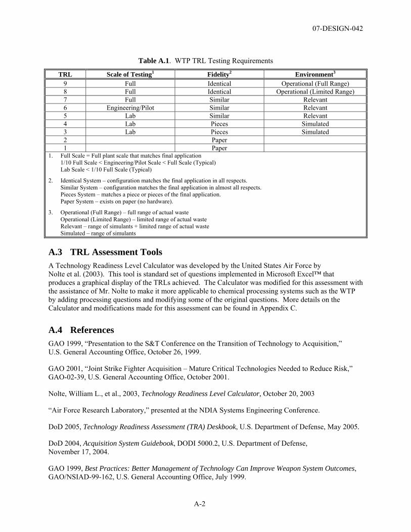
07-DESIGN-042
A-2
Table A.1. WTP TRL Testing Requirements
TRL Scale of Testing1 Fidelity2 Environment3 9 Full Identical Operational (Full Range) 8 Full Identical Operational (Limited Range) 7 Full Similar Relevant 6 Engineering/Pilot Similar Relevant 5 Lab Similar Relevant 4 Lab Pieces Simulated 3 Lab Pieces Simulated 2 Paper 1 Paper
1. Full Scale = Full plant scale that matches final application 1/10 Full Scale < Engineering/Pilot Scale < Full Scale (Typical) Lab Scale < 1/10 Full Scale (Typical)
2. Identical System – configuration matches the final application in all respects. Similar System – configuration matches the final application in almost all respects. Pieces System – matches a piece or pieces of the final application. Paper System – exists on paper (no hardware).
3. Operational (Full Range) – full range of actual waste Operational (Limited Range) – limited range of actual waste Relevant – range of simulants + limited range of actual waste Simulated – range of simulants
A.3 TRL Assessment Tools A Technology Readiness Level Calculator was developed by the United States Air Force by Nolte et al. (2003). This tool is standard set of questions implemented in Microsoft Excel™ that produces a graphical display of the TRLs achieved. The Calculator was modified for this assessment with the assistance of Mr. Nolte to make it more applicable to chemical processing systems such as the WTP by adding processing questions and modifying some of the original questions. More details on the Calculator and modifications made for this assessment can be found in Appendix C.
A.4 References GAO 1999, “Presentation to the S&T Conference on the Transition of Technology to Acquisition,” U.S. General Accounting Office, October 26, 1999.
GAO 2001, “Joint Strike Fighter Acquisition – Mature Critical Technologies Needed to Reduce Risk,” GAO-02-39, U.S. General Accounting Office, October 2001.
Nolte, William L., et al., 2003, Technology Readiness Level Calculator, October 20, 2003
“Air Force Research Laboratory,” presented at the NDIA Systems Engineering Conference.
DoD 2005, Technology Readiness Assessment (TRA) Deskbook, U.S. Department of Defense, May 2005.
DoD 2004, Acquisition System Guidebook, DODI 5000.2, U.S. Department of Defense, November 17, 2004.
GAO 1999, Best Practices: Better Management of Technology Can Improve Weapon System Outcomes, GAO/NSIAD-99-162, U.S. General Accounting Office, July 1999.
07-DESIGN-042
A-3
Graettinger, Caroline P., et al., 2002, Using the Technology Readiness Levels Scale to Support Technology Management in the DoD’s ATD/STO Environments: A Findings and Recommendations Report Conducted for Army CECOM, Carnegie Mellon Software Engineering Institute, CMU/SEI-2002-SR-027, September 2002.
Mankins, John C., 1995, Technology Readiness Levels: A White Paper, NASA, Office of Space Access and Technology, Advanced Concepts Office, April 6, 1995.
Nolte, William L., et al., 2003, “Technology Readiness Level Calculator,” Air Force Research Laboratory, presented at the NDIA Systems Engineering Conference. http://en.wikipedia.org/wiki/Technology_Readiness_Level, October 20, 2003.
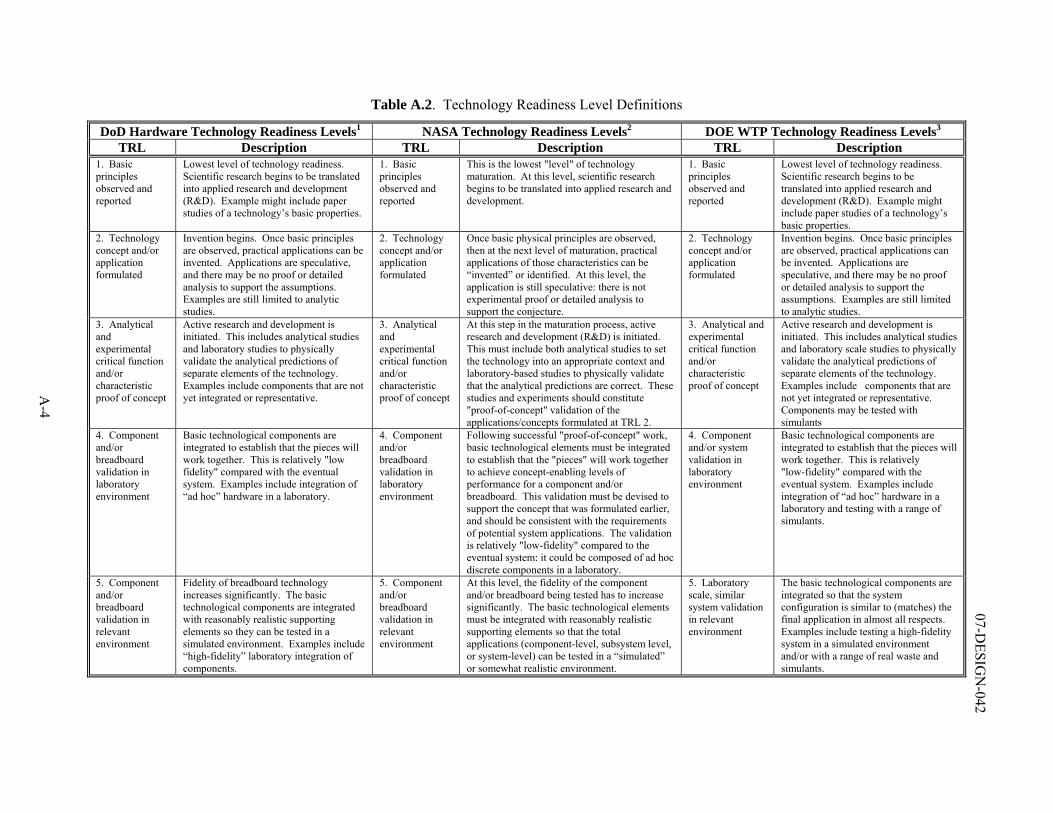
A-4
07-DESIG
N-042
Table A.2. Technology Readiness Level Definitions
DoD Hardware Technology Readiness Levels1 NASA Technology Readiness Levels2 DOE WTP Technology Readiness Levels3 TRL Description TRL Description TRL Description
1. Basic principles observed and reported
Lowest level of technology readiness. Scientific research begins to be translated into applied research and development (R&D). Example might include paper studies of a technology’s basic properties.
1. Basic principles observed and reported
This is the lowest "level" of technology maturation. At this level, scientific research begins to be translated into applied research and development.
1. Basic principles observed and reported
Lowest level of technology readiness. Scientific research begins to be translated into applied research and development (R&D). Example might include paper studies of a technology’s basic properties.
2. Technology concept and/or application formulated
Invention begins. Once basic principles are observed, practical applications can be invented. Applications are speculative, and there may be no proof or detailed analysis to support the assumptions. Examples are still limited to analytic studies.
2. Technology concept and/or application formulated
Once basic physical principles are observed, then at the next level of maturation, practical applications of those characteristics can be “invented” or identified. At this level, the application is still speculative: there is not experimental proof or detailed analysis to support the conjecture.
2. Technology concept and/or application formulated
Invention begins. Once basic principles are observed, practical applications can be invented. Applications are speculative, and there may be no proof or detailed analysis to support the assumptions. Examples are still limited to analytic studies.
3. Analytical and experimental critical function and/or characteristic proof of concept
Active research and development is initiated. This includes analytical studies and laboratory studies to physically validate the analytical predictions of separate elements of the technology. Examples include components that are not yet integrated or representative.
3. Analytical and experimental critical function and/or characteristic proof of concept
At this step in the maturation process, active research and development (R&D) is initiated. This must include both analytical studies to set the technology into an appropriate context and laboratory-based studies to physically validate that the analytical predictions are correct. These studies and experiments should constitute "proof-of-concept" validation of the applications/concepts formulated at TRL 2.
3. Analytical and experimental critical function and/or characteristic proof of concept
Active research and development is initiated. This includes analytical studies and laboratory scale studies to physically validate the analytical predictions of separate elements of the technology. Examples include components that are not yet integrated or representative. Components may be tested with simulants
4. Component and/or breadboard validation in laboratory environment
Basic technological components are integrated to establish that the pieces will work together. This is relatively "low fidelity" compared with the eventual system. Examples include integration of “ad hoc” hardware in a laboratory.
4. Component and/or breadboard validation in laboratory environment
Following successful "proof-of-concept" work, basic technological elements must be integrated to establish that the "pieces" will work together to achieve concept-enabling levels of performance for a component and/or breadboard. This validation must be devised to support the concept that was formulated earlier, and should be consistent with the requirements of potential system applications. The validation is relatively "low-fidelity" compared to the eventual system: it could be composed of ad hoc discrete components in a laboratory.
4. Component and/or system validation in laboratory environment
Basic technological components are integrated to establish that the pieces will work together. This is relatively "low-fidelity" compared with the eventual system. Examples include integration of “ad hoc” hardware in a laboratory and testing with a range of simulants.
5. Component and/or breadboard validation in relevant environment
Fidelity of breadboard technology increases significantly. The basic technological components are integrated with reasonably realistic supporting elements so they can be tested in a simulated environment. Examples include “high-fidelity” laboratory integration of components.
5. Component and/or breadboard validation in relevant environment
At this level, the fidelity of the component and/or breadboard being tested has to increase significantly. The basic technological elements must be integrated with reasonably realistic supporting elements so that the total applications (component-level, subsystem level, or system-level) can be tested in a “simulated” or somewhat realistic environment.
5. Laboratory scale, similar system validation in relevant environment
The basic technological components are integrated so that the system configuration is similar to (matches) the final application in almost all respects. Examples include testing a high-fidelity system in a simulated environment and/or with a range of real waste and simulants.
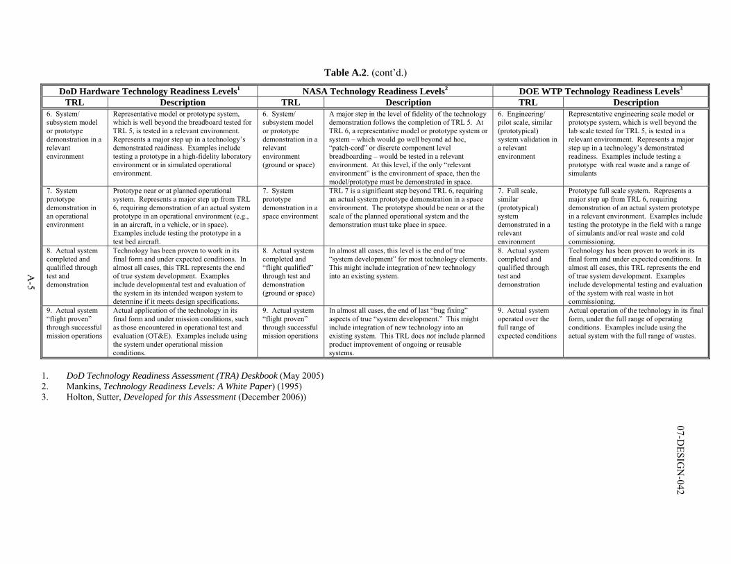
A-5
07-DESIG
N-042
Table A.2. (cont’d.)
DoD Hardware Technology Readiness Levels1 NASA Technology Readiness Levels2 DOE WTP Technology Readiness Levels3 TRL Description TRL Description TRL Description
6. System/ subsystem model or prototype demonstration in a relevant environment
Representative model or prototype system, which is well beyond the breadboard tested for TRL 5, is tested in a relevant environment. Represents a major step up in a technology’s demonstrated readiness. Examples include testing a prototype in a high-fidelity laboratory environment or in simulated operational environment.
6. System/ subsystem model or prototype demonstration in a relevant environment (ground or space)
A major step in the level of fidelity of the technology demonstration follows the completion of TRL 5. At TRL 6, a representative model or prototype system or system – which would go well beyond ad hoc, “patch-cord” or discrete component level breadboarding – would be tested in a relevant environment. At this level, if the only “relevant environment” is the environment of space, then the model/prototype must be demonstrated in space.
6. Engineering/ pilot scale, similar (prototypical) system validation in a relevant environment
Representative engineering scale model or prototype system, which is well beyond the lab scale tested for TRL 5, is tested in a relevant environment. Represents a major step up in a technology’s demonstrated readiness. Examples include testing a prototype with real waste and a range of simulants
7. System prototype demonstration in an operational environment
Prototype near or at planned operational system. Represents a major step up from TRL 6, requiring demonstration of an actual system prototype in an operational environment (e.g., in an aircraft, in a vehicle, or in space). Examples include testing the prototype in a test bed aircraft.
7. System prototype demonstration in a space environment
TRL 7 is a significant step beyond TRL 6, requiring an actual system prototype demonstration in a space environment. The prototype should be near or at the scale of the planned operational system and the demonstration must take place in space.
7. Full scale, similar (prototypical) system demonstrated in a relevant environment
Prototype full scale system. Represents a major step up from TRL 6, requiring demonstration of an actual system prototype in a relevant environment. Examples include testing the prototype in the field with a range of simulants and/or real waste and cold commissioning.
8. Actual system completed and qualified through test and demonstration
Technology has been proven to work in its final form and under expected conditions. In almost all cases, this TRL represents the end of true system development. Examples include developmental test and evaluation of the system in its intended weapon system to determine if it meets design specifications.
8. Actual system completed and “flight qualified” through test and demonstration (ground or space)
In almost all cases, this level is the end of true “system development” for most technology elements. This might include integration of new technology into an existing system.
8. Actual system completed and qualified through test and demonstration
Technology has been proven to work in its final form and under expected conditions. In almost all cases, this TRL represents the end of true system development. Examples include developmental testing and evaluation of the system with real waste in hot commissioning.
9. Actual system “flight proven” through successful mission operations
Actual application of the technology in its final form and under mission conditions, such as those encountered in operational test and evaluation (OT&E). Examples include using the system under operational mission conditions.
9. Actual system “flight proven” through successful mission operations
In almost all cases, the end of last “bug fixing” aspects of true “system development.” This might include integration of new technology into an existing system. This TRL does not include planned product improvement of ongoing or reusable systems.
9. Actual system operated over the full range of expected conditions
Actual operation of the technology in its final form, under the full range of operating conditions. Examples include using the actual system with the full range of wastes.
1. DoD Technology Readiness Assessment (TRA) Deskbook (May 2005) 2. Mankins, Technology Readiness Levels: A White Paper) (1995) 3. Holton, Sutter, Developed for this Assessment (December 2006))

07-DESIGN-042
Appendix B
Determination of Critical Technology Elements

07-DESIGN-042
B-1
Appendix B Determination of Critical Technology Elements
The working definition of the critical technology element (CTE) as defined in the Technology Readiness Assessment (TRA) Deskbook (2005) was used as a basis for identification of CTEs for the Waste Treatment and Immobilization Plant (WTP). The working definition is as follows:
A technology element is “critical” if the system being acquired depends on the technology element to meet operational requirements (with acceptable development, cost, and schedule and with acceptable production and operations costs) and if the technology element or its application is either new or novel.
Said another way, an element that is new or novel or being used in a new or novel way is critical if it is necessary to achieve the successful development of a system, its acquisition, or its operational utility.
The WTP Project is divided into five project elements:
• Analytical Laboratory (LAB)
• Balance of Facilities (BOF)
• LAW Waste Vitrification Facility (LAW)
• HLW Waste Vitrification Facility (HLW)
• Pretreatment (PT) Facility
Within each project element, the specific design features of the facility are divided into “systems.” Thus, for convenience, the identification of the CTEs was done on a system basis. Most systems within the WTP facility are unique to the five project elements identified above. However, some selected systems are common to the treatment facilities (LAB, LAW, HLW, and PT). Where appropriate, these common systems were allocated to the five project elements identified above.
The process for identification of the CTEs for the Analytical Laboratory/Balance of Facilities/LAW Vitrification Facility (LAB/BOF/LAW) involved two steps. These were:
1. The complete list of systems for LAB/BOF/LAW was initially screened by the Assessment Team (Appendix E) for potential CTEs. Systems directly involved in the processing of the tank waste, or handling of the primary products (immobilized LAW and secondary wastes) were identified as potential CTEs. The complete list of systems and those identified as potential CTEs are identified in Tables B.1, B.2, and B.3 for the LAB, BOF, and LAW facilities, respectively.
2. The final set of CTEs was determined by assessing the potential CTEs against the two sets of questions presented in Table B.4. A CTE is determined if there is a positive response to at least one of the questions in each of the question sets. This final assessment of the CTEs was completed jointly by the Assessment Team and the WTP Project Technology and Engineering staff.
The specific responses to each of the questions for each potential CTE are provided in Table B.5. The LAW Container Finishing Handling System was divided into five separate subsystems (1-Weigh, Inert Fill, and Glass Sampling; 2-Container Sealing; 3-Container Decontamination and Surface
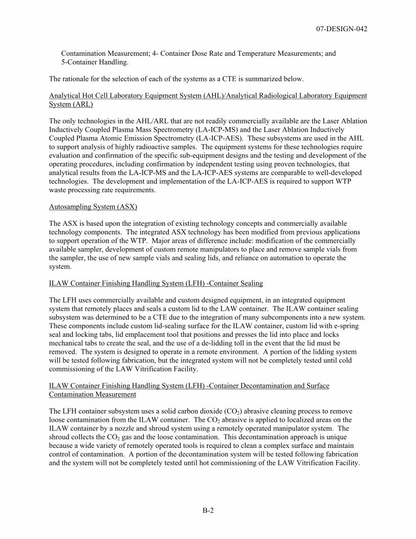
07-DESIGN-042
B-2
Contamination Measurement; 4- Container Dose Rate and Temperature Measurements; and 5-Container Handling.
The rationale for the selection of each of the systems as a CTE is summarized below.
Analytical Hot Cell Laboratory Equipment System (AHL)/Analytical Radiological Laboratory Equipment System (ARL)
The only technologies in the AHL/ARL that are not readily commercially available are the Laser Ablation Inductively Coupled Plasma Mass Spectrometry (LA-ICP-MS) and the Laser Ablation Inductively Coupled Plasma Atomic Emission Spectrometry (LA-ICP-AES). These subsystems are used in the AHL to support analysis of highly radioactive samples. The equipment systems for these technologies require evaluation and confirmation of the specific sub-equipment designs and the testing and development of the operating procedures, including confirmation by independent testing using proven technologies, that analytical results from the LA-ICP-MS and the LA-ICP-AES systems are comparable to well-developed technologies. The development and implementation of the LA-ICP-AES is required to support WTP waste processing rate requirements.
Autosampling System (ASX)
The ASX is based upon the integration of existing technology concepts and commercially available technology components. The integrated ASX technology has been modified from previous applications to support operation of the WTP. Major areas of difference include: modification of the commercially available sampler, development of custom remote manipulators to place and remove sample vials from the sampler, the use of new sample vials and sealing lids, and reliance on automation to operate the system.
ILAW Container Finishing Handling System (LFH) -Container Sealing
The LFH uses commercially available and custom designed equipment, in an integrated equipment system that remotely places and seals a custom lid to the LAW container. The ILAW container sealing subsystem was determined to be a CTE due to the integration of many subcomponents into a new system. These components include custom lid-sealing surface for the ILAW container, custom lid with e-spring seal and locking tabs, lid emplacement tool that positions and presses the lid into place and locks mechanical tabs to create the seal, and the use of a de-lidding toll in the event that the lid must be removed. The system is designed to operate in a remote environment. A portion of the lidding system will be tested following fabrication, but the integrated system will not be completely tested until cold commissioning of the LAW Vitrification Facility.
ILAW Container Finishing Handling System (LFH) -Container Decontamination and Surface Contamination Measurement
The LFH container subsystem uses a solid carbon dioxide (CO2) abrasive cleaning process to remove loose contamination from the ILAW container. The CO2 abrasive is applied to localized areas on the ILAW container by a nozzle and shroud system using a remotely operated manipulator system. The shroud collects the CO2 gas and the loose contamination. This decontamination approach is unique because a wide variety of remotely operated tools is required to clean a complex surface and maintain control of contamination. A portion of the decontamination system will be tested following fabrication and the system will not be completely tested until hot commissioning of the LAW Vitrification Facility.
07-DESIGN-042
B-3
LAW Melter Feed Process System (LFP)
The LFP prepares the LAW melter feed by blending treated low-activity waste and glass-forming chemicals. The remote, dry addition of glass-forming chemicals is novel (at the Savannah River Defense Waste Processing Facility [DWPF], glass formers were slurried ahead of time). The unique composition of the glass-forming chemicals, comprised mostly of industrial quality minerals, can lead to dusting of the glass formers on the liquid surface leading to potential blockage in the vessel ventilation system and inhomogeneous feed. The LAW melter feed preparation system relies on the integration of custom designed (e.g., vessels) and vendor-designed, commercially available equipment (e.g., mechanical mixer).
LAW Melter Process System (LMP)
The LAW melter design used for the WTP represents the largest capacity (design capacity 15 metric tons glass per day [MT/day]) melter used in the United States for the vitrification of radioactive waste. In addition, some of the equipment components used in the melter, such as the bubblers and multiple feed nozzles, are unique to this process system, and there are some issues with the availability of the materials required for the components of the melter.
LAW Melter Offgas System/LAW Secondary Offgas/Vessel Vent Process Systems (LOP/LVP)
The specific sub-components that comprise the LOP are a combination of unique WTP designs (e.g., film cooler, submerged bed scrubber) and vendor designed, commercially available equipment (e.g., high-efficiency mist eliminator, wet electrostatic precipitator, mercury (Hg) catalyst skid, and organic destruction catalyst skid). The system as proposed for the LAW Vitrification Facility has not been used in the proposed configuration or offgas environment prior to the WTP Project.
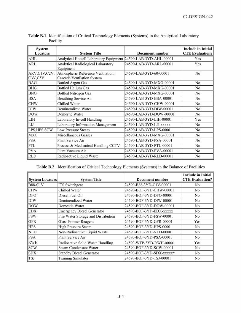
07-DESIGN-042
B-4
Table B.1. Identification of Critical Technology Elements (Systems) in the Analytical Laboratory Facility
System Locators System Title Document number
Include in Initial CTE Evaluation?
AHL Analytical Hotcell Laboratory Equipment 24590-LAB-3YD-AHL-00001 Yes ARL Analytical Radiological Laboratory
Equipment 24590-LAB-3YD-ARL-00001 Yes
ARV,C1V,C2V,C3V,C5V
Atmospheric Reference Ventilation; Cascade Ventilation System
24590-LAB-3YD-60-00001 No
BAG Bottled Argon Gas 24590-LAB-3YD-MXG-00001 No BHG Bottled Helium Gas 24590-LAB-3YD-MXG-00001 No BNG Bottled Nitrogen Gas 24590-LAB-3YD-MXG-00001 No BSA Breathing Service Air 24590-LAB-3YD-BSA-00001 No CHW Chilled Water 24590-LAB-3YD-CHW-00001 No DIW Demineralized Water 24590-LAB-3YD-DIW-00001 No DOW Domestic Water 24590-LAB-3YD-DOW-00001 No LIH Laboratory In-cell Handling 24590-LAB-3YD-LIH-00001 Yes LIJ Laboratory Information Management 24590-LAB-3YD-LIJ-xxxxx No LPS,HPS,SCW Low Pressure Steam 24590-LAB-3YD-LPS-00001 No MXG Miscellaneous Gasses 24590-LAB-3YD-MXG-00001 No PSA Plant Service Air 24590-LAB-3YD-PSA-00001 No PTL Process & Mechanical Handling CCTV 24590-LAB-3YD-PTL-00001 No PVA Plant Vacuum Air 24590-LAB-3YD-PVA-00001 No RLD Radioactive Liquid Waste 24590-LAB-3YD-RLD-00001 No
Table B.2. Identification of Critical Technology Elements (Systems) in the Balance of Facilities
System Locators System Title Document number Include in Initial CTE Evaluation?
B88-C1V ITS Switchgear 24590-B88-3YD-C1V-00001 No CHW Chilled Water 24590-BOF-3YD-CHW-00001 No DFO Diesel Fuel Oil 24590-BOF-3YD-DFO-00001 No DIW Demineralized Water 24590-BOF-3YD-DIW-00001 No DOW Domestic Water 24590-BOF-3YD-DOW-00001 No EDX Emergency Diesel Generator 24590-BOF-3YD-EDX-xxxxx No FSW Fire Water Storage and Distribution 24590-BOF-3YD-FSW-00001 No GFR Glass Former Reagent 24590-BOF-3YD-GFR-00001 Yes HPS High Pressure Steam 24590-BOF-3YD-HPS-00001 No NLD Non-Radioactive Liquid Waste 24590-BOF-3YD-NLD-00001 No PSA Plant Service Air 24590-BOF-3YD-PSA-00001 No RWH Radioactive Solid Waste Handling 24590-WTP-3YD-RWH-00001 Yes SCW Steam Condensate Water 24590-BOF-3YD-SCW-00001 No SDX Standby Diesel Generator 24590-BOF-3YD-SDX-xxxxx* No TSJ Training Simulator 24590-BOF-3YD-TSJ-00001 No
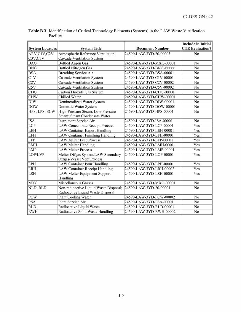
07-DESIGN-042
B-5
Table B.3. Identification of Critical Technology Elements (Systems) in the LAW Waste Vitrification Facility
System Locators System Title Document Number Include in Initial CTE Evaluation?
ARV,C1V,C2V, C3V,C5V
Atmospheric Reference Ventilation; Cascade Ventilation System
24590-LAW-3YD-20-00003 No
BAG Bottled Argon Gas 24590-LAW-3YD-MXG-00001 No BNG Bottled Nitrogen Gas 24590-LAW-3YD-BNG-xxxxx No BSA Breathing Service Air 24590-LAW-3YD-BSA-00001 No C1V Cascade Ventilation System 24590-LAW-3YD-C1V-00001 No C2V Cascade Ventilation System 24590-LAW-3YD-C2V-00002 No C5V Cascade Ventilation System 24590-LAW-3YD-C5V-00002 No CDG Carbon Dioxide Gas System 24590-LAW-3YD-CDG-00001 No CHW Chilled Water 24590-LAW-3YD-CHW-00001 No DIW Demineralized Water System 24590-LAW-3YD-DIW-00001 No DOW Domestic Water System 24590-LAW-3YD-DOW-00001 No HPS; LPS; SCW High-Pressure Steam; Low-Pressure
Steam; Steam Condensate Water 24590-LAW-3YD-HPS-00001 No
ISA Instrument Service Air 24590-LAW-3YD-ISA-00001 No LCP LAW Concentrate Receipt Process 24590-LAW-3YD-LCP-00001 Yes LEH LAW Container Export Handling 24590-LAW-3YD-LEH-00001 Yes LFH LAW Container Finishing Handling 24590-LAW-3YD-LFH-00001 Yes LFP LAW Melter Feed Process 24590-LAW-3YD-LFP-00001 Yes LMH LAW Melter Handling 24590-LAW-3YD-LMH-00001 Yes LMP LAW Melter Process 24590-LAW-3YD-LMP-00001 Yes LOP/LVP Melter Offgas System/LAW Secondary
Offgas/Vessel Vent Process 24590-LAW-3YD-LOP-00001 Yes
LPH LAW Container Pour Handling 24590-LAW-3YD-LPH-00001 Yes LRH LAW Container Receipt Handling 24590-LAW-3YD-LRH-00002 Yes LSH LAW Melter Equipment Support
Handling 24590-LAW-3YD-LSH-00001 Yes
MXG Miscellaneous Gasses 24590-LAW-3YD-MXG-00001 No NLD; RLD Non-radioactive Liquid Waste Disposal;
Radioactive Liquid Waste Disposal 24590-LAW-3YD-20-00001 No
PCW Plant Cooling Water 24590-LAW-3YD-PCW-00002 No PSA Plant Service Air 24590-LAW-3YD-PSA-00001 No RLD Radioactive Liquid Waste 24590-LAW-3YD-RLD-00001 No RWH Radioactive Solid Waste Handling 24590-LAW-3YD-RWH-00002 No
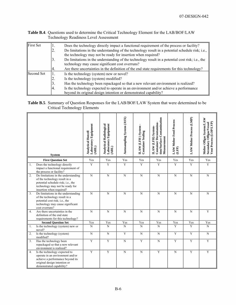
07-DESIGN-042
B-6
Table B.4. Questions used to determine the Critical Technology Element for the LAB/BOF/LAW Technology Readiness Level Assessment
First Set 1. Does the technology directly impact a functional requirement of the process or facility? 2. Do limitations in the understanding of the technology result in a potential schedule risk; i.e.,
the technology may not be ready for insertion when required? 3. Do limitations in the understanding of the technology result in a potential cost risk; i.e., the
technology may cause significant cost overruns? 4. Are there uncertainties in the definition of the end state requirements for this technology?
Second Set 1. Is the technology (system) new or novel? 2. Is the technology (system) modified? 3. Has the technology been repackaged so that a new relevant environment is realized? 4. Is the technology expected to operate in an environment and/or achieve a performance
beyond its original design intention or demonstrated capability?
Table B.5. Summary of Question Responses for the LAB/BOF/LAW System that were determined to be Critical Technology Elements
System Ana
lytic
al H
otce
ll L
abor
ator
y E
quip
men
t (A
HL
)
Ana
lytic
al R
adio
logi
cal
Lab
orat
ory
Equ
ipm
ent
(AR
L)
Aut
osam
plin
g Sy
stem
(ASX
)
ILA
W (L
FH )
Syst
em -
Con
tain
er S
ealin
g
ILA
W (L
FH) S
yste
m-
Con
tain
er D
econ
tam
ina-
tion/
Surf
ace-
Con
tam
inat
ion
Mea
sure
men
t
LA
W M
elte
r Fe
ed P
roce
ss
(LFP
)
LA
W M
elte
r Pr
oces
s (L
MP)
Mel
ter
Off
gas S
yste
m/L
AW
Se
cond
ary
Off
gas/
Ves
sel
Ven
t Pro
cess
(LO
P/L
VP)
First Question Set Yes Yes Yes Yes Yes Yes Yes Yes 1. Does the technology directly
impact a functional requirement of the process or facility?
Y Y Y Y Y Y Y Y
2. Do limitations in the understanding of the technology result in a potential schedule risk; i.e., the technology may not be ready for insertion when required?
N N N N N N N N
3. Do limitations in the understanding of the technology result in a potential cost risk; i.e., the technology may cause significant cost overruns?
N N N N N N N N
4. Are there uncertainties in the definition of the end state requirements for this technology?
N N N N N N N Y
Second Question Set Yes Yes Yes Yes Yes Yes Yes Yes 1. Is the technology (system) new or
novel? N N N N N Y Y N
2. Is the technology (system) modified?
N N Y N N Y Y N
3. Has the technology been repackaged so that a new relevant environment is realized?
Y Y N Y N Y Y Y
4. Is the technology expected to operate in an environment and/or achieve a performance beyond its original design intention or demonstrated capability?
Y Y N N Y N Y Y
07-DESIGN-042
Appendix C
Technology Readiness Level Calculator as Modified for DOE Office of Environmental Management

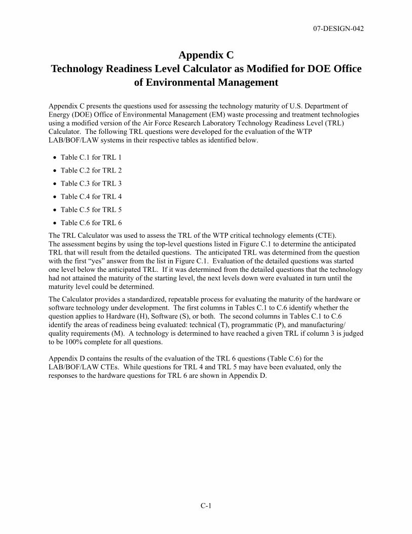
07-DESIGN-042
C-1
Appendix C Technology Readiness Level Calculator as Modified for DOE Office
of Environmental Management
Appendix C presents the questions used for assessing the technology maturity of U.S. Department of Energy (DOE) Office of Environmental Management (EM) waste processing and treatment technologies using a modified version of the Air Force Research Laboratory Technology Readiness Level (TRL) Calculator. The following TRL questions were developed for the evaluation of the WTP LAB/BOF/LAW systems in their respective tables as identified below.
• Table C.1 for TRL 1
• Table C.2 for TRL 2
• Table C.3 for TRL 3
• Table C.4 for TRL 4
• Table C.5 for TRL 5
• Table C.6 for TRL 6
The TRL Calculator was used to assess the TRL of the WTP critical technology elements (CTE). The assessment begins by using the top-level questions listed in Figure C.1 to determine the anticipated TRL that will result from the detailed questions. The anticipated TRL was determined from the question with the first “yes” answer from the list in Figure C.1. Evaluation of the detailed questions was started one level below the anticipated TRL. If it was determined from the detailed questions that the technology had not attained the maturity of the starting level, the next levels down were evaluated in turn until the maturity level could be determined.
The Calculator provides a standardized, repeatable process for evaluating the maturity of the hardware or software technology under development. The first columns in Tables C.1 to C.6 identify whether the question applies to Hardware (H), Software (S), or both. The second columns in Tables C.1 to C.6 identify the areas of readiness being evaluated: technical (T), programmatic (P), and manufacturing/ quality requirements (M). A technology is determined to have reached a given TRL if column 3 is judged to be 100% complete for all questions.
Appendix D contains the results of the evaluation of the TRL 6 questions (Table C.6) for the LAB/BOF/LAW CTEs. While questions for TRL 4 and TRL 5 may have been evaluated, only the responses to the hardware questions for TRL 6 are shown in Appendix D.
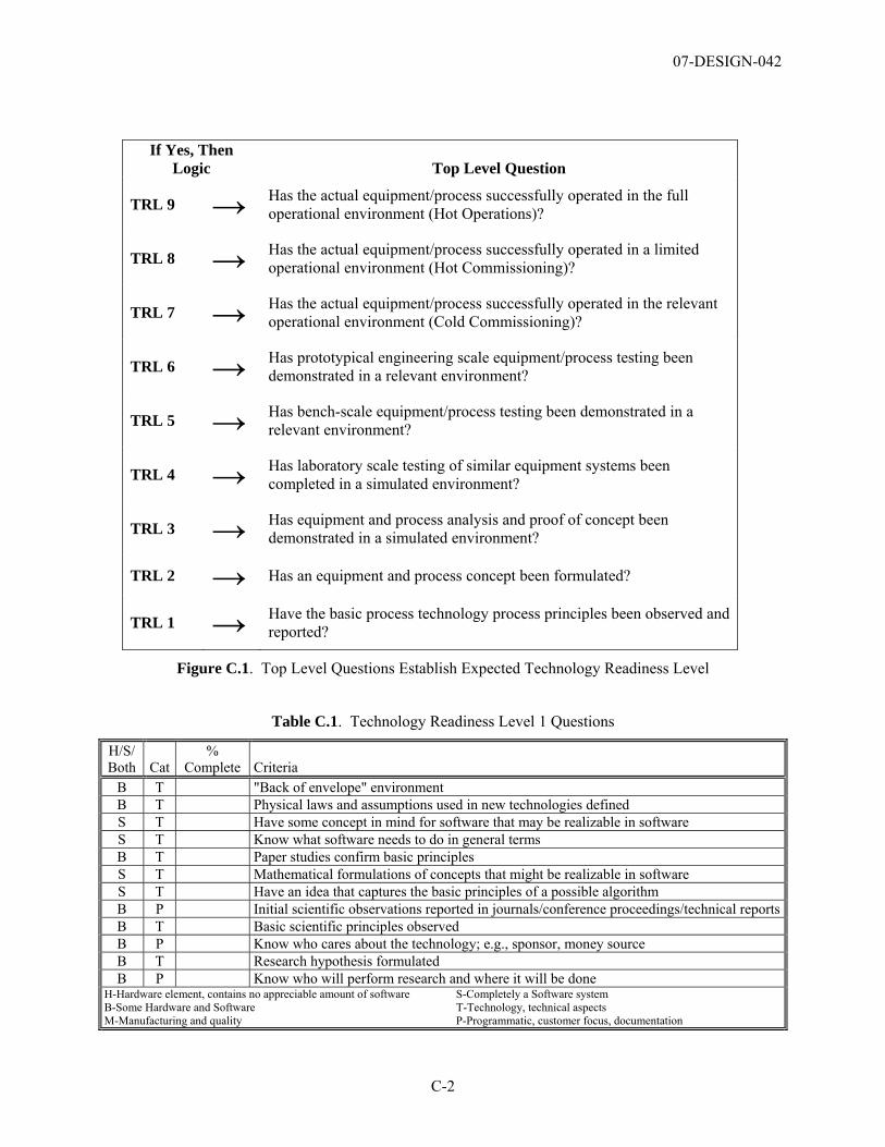
07-DESIGN-042
C-2
If Yes, Then Logic Top Level Question
TRL 9 → Has the actual equipment/process successfully operated in the full operational environment (Hot Operations)?
TRL 8 → Has the actual equipment/process successfully operated in a limited operational environment (Hot Commissioning)?
TRL 7 → Has the actual equipment/process successfully operated in the relevant operational environment (Cold Commissioning)?
TRL 6 → Has prototypical engineering scale equipment/process testing been demonstrated in a relevant environment?
TRL 5 → Has bench-scale equipment/process testing been demonstrated in a relevant environment?
TRL 4 → Has laboratory scale testing of similar equipment systems been completed in a simulated environment?
TRL 3 → Has equipment and process analysis and proof of concept been demonstrated in a simulated environment?
TRL 2 → Has an equipment and process concept been formulated?
TRL 1 → Have the basic process technology process principles been observed and reported?
Figure C.1. Top Level Questions Establish Expected Technology Readiness Level
Table C.1. Technology Readiness Level 1 Questions
H/S/ Both Cat
% Complete Criteria
B T "Back of envelope" environment B T Physical laws and assumptions used in new technologies defined S T Have some concept in mind for software that may be realizable in software S T Know what software needs to do in general terms B T Paper studies confirm basic principles S T Mathematical formulations of concepts that might be realizable in software S T Have an idea that captures the basic principles of a possible algorithm B P Initial scientific observations reported in journals/conference proceedings/technical reportsB T Basic scientific principles observed B P Know who cares about the technology; e.g., sponsor, money source B T Research hypothesis formulated B P Know who will perform research and where it will be done
H-Hardware element, contains no appreciable amount of software S-Completely a Software system B-Some Hardware and Software T-Technology, technical aspects M-Manufacturing and quality P-Programmatic, customer focus, documentation
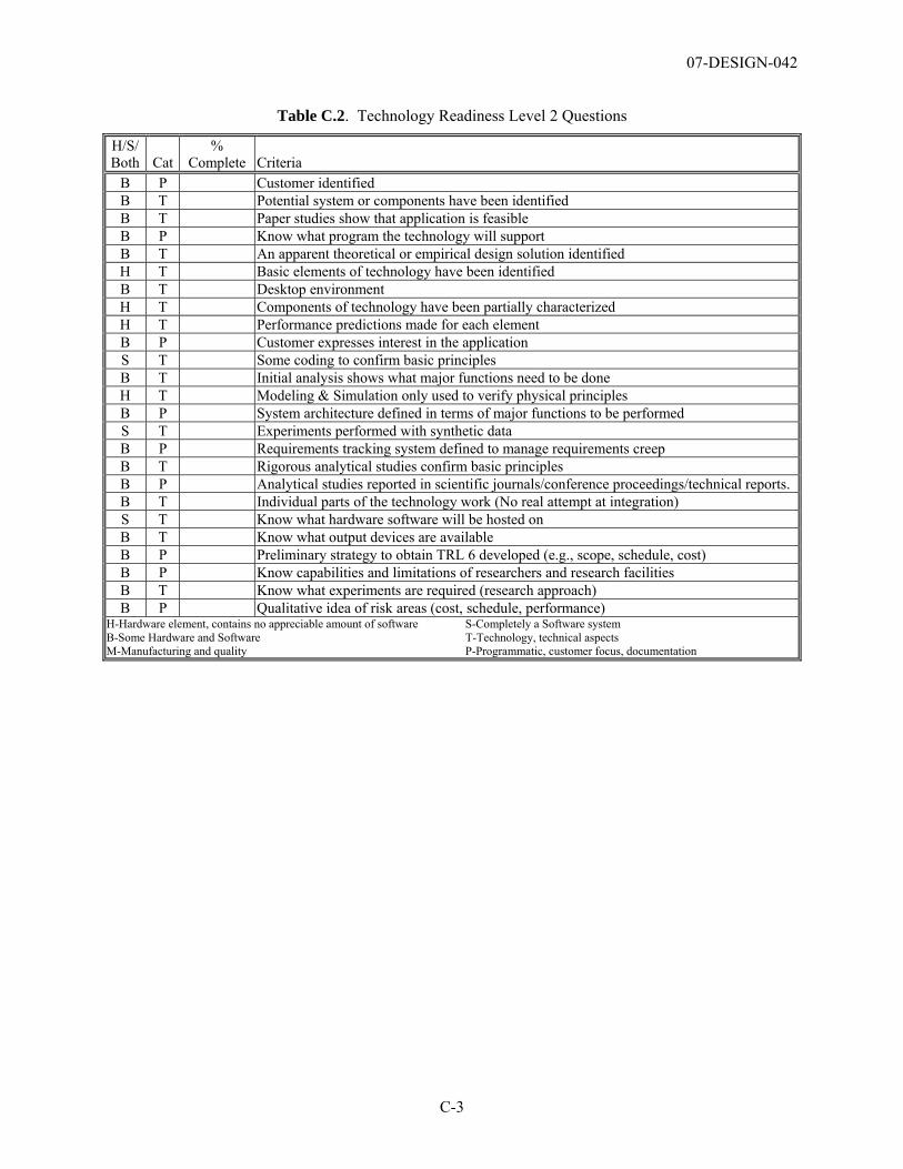
07-DESIGN-042
C-3
Table C.2. Technology Readiness Level 2 Questions
H/S/ Both Cat
% Complete Criteria
B P Customer identified B T Potential system or components have been identified B T Paper studies show that application is feasible B P Know what program the technology will support B T An apparent theoretical or empirical design solution identified H T Basic elements of technology have been identified B T Desktop environment H T Components of technology have been partially characterized H T Performance predictions made for each element B P Customer expresses interest in the application S T Some coding to confirm basic principles B T Initial analysis shows what major functions need to be done H T Modeling & Simulation only used to verify physical principles B P System architecture defined in terms of major functions to be performed S T Experiments performed with synthetic data B P Requirements tracking system defined to manage requirements creep B T Rigorous analytical studies confirm basic principles B P Analytical studies reported in scientific journals/conference proceedings/technical reports. B T Individual parts of the technology work (No real attempt at integration) S T Know what hardware software will be hosted on B T Know what output devices are available B P Preliminary strategy to obtain TRL 6 developed (e.g., scope, schedule, cost) B P Know capabilities and limitations of researchers and research facilities B T Know what experiments are required (research approach) B P Qualitative idea of risk areas (cost, schedule, performance)
H-Hardware element, contains no appreciable amount of software S-Completely a Software system B-Some Hardware and Software T-Technology, technical aspects M-Manufacturing and quality P-Programmatic, customer focus, documentation
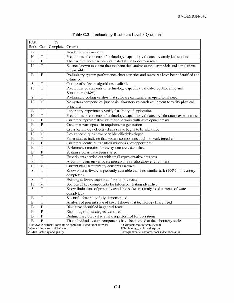
07-DESIGN-042
C-4
Table C.3. Technology Readiness Level 3 Questions
H/S/ Both Cat
% Complete Criteria
B T Academic environment H T Predictions of elements of technology capability validated by analytical studies B P The basic science has been validated at the laboratory scale H T Science known to extent that mathematical and/or computer models and simulations
are possible B P Preliminary system performance characteristics and measures have been identified and
estimated S T Outline of software algorithms available H T Predictions of elements of technology capability validated by Modeling and
Simulation (M&S) S T Preliminary coding verifies that software can satisfy an operational need H M No system components, just basic laboratory research equipment to verify physical
principles B T Laboratory experiments verify feasibility of application H T Predictions of elements of technology capability validated by laboratory experiments B P Customer representative identified to work with development team B P Customer participates in requirements generation B T Cross technology effects (if any) have begun to be identified H M Design techniques have been identified/developed B T Paper studies indicate that system components ought to work together B P Customer identifies transition window(s) of opportunity B T Performance metrics for the system are established B P Scaling studies have been started S T Experiments carried out with small representative data sets S T Algorithms run on surrogate processor in a laboratory environment H M Current manufacturability concepts assessed S T Know what software is presently available that does similar task (100% = Inventory
completed) S T Existing software examined for possible reuse H M Sources of key components for laboratory testing identified S T Know limitations of presently available software (analysis of current software
completed) B T Scientific feasibility fully demonstrated B T Analysis of present state of the art shows that technology fills a need B P Risk areas identified in general terms B P Risk mitigation strategies identified B P Rudimentary best value analysis performed for operations B P The individual system components have been tested at the laboratory scale
H-Hardware element, contains no appreciable amount of software S-Completely a Software system B-Some Hardware and Software T-Technology, technical aspects M-Manufacturing and quality P-Programmatic, customer focus, documentation
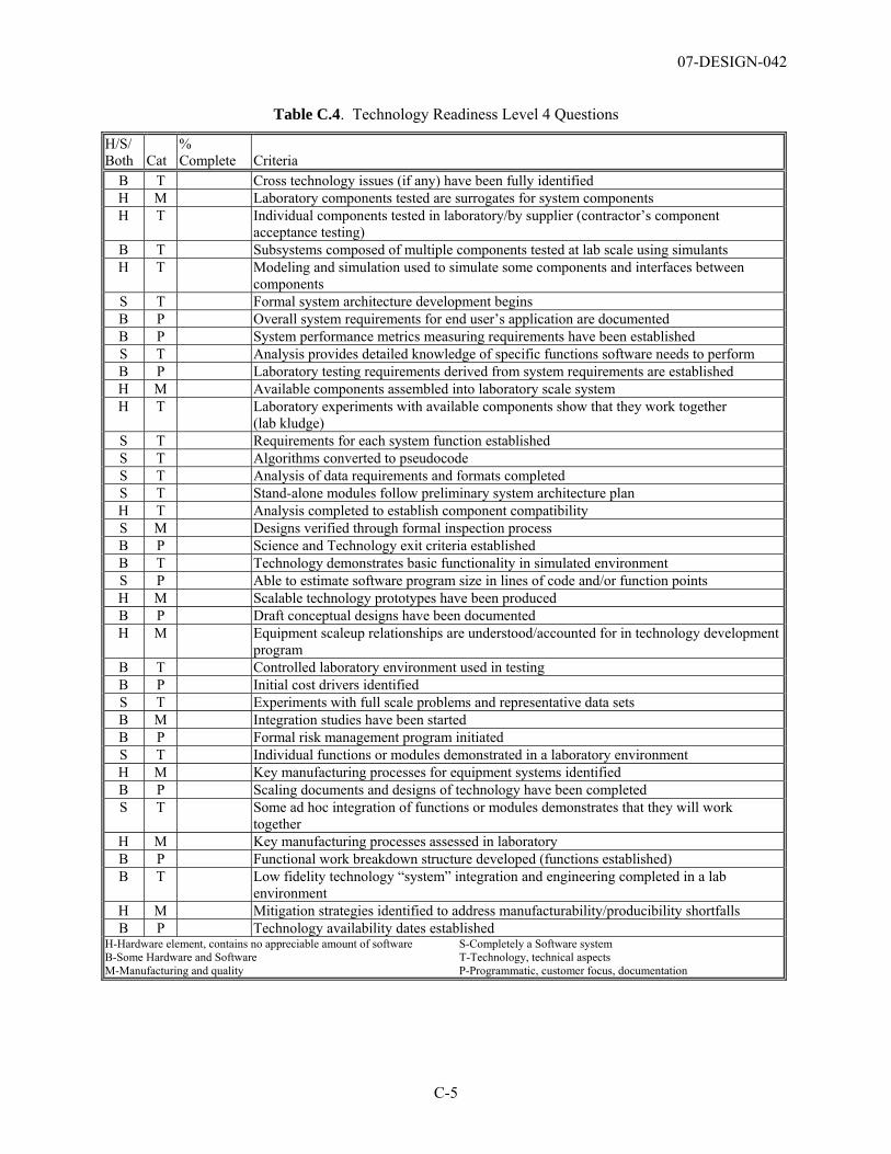
07-DESIGN-042
C-5
Table C.4. Technology Readiness Level 4 Questions
H/S/ Both Cat
% Complete Criteria
B T Cross technology issues (if any) have been fully identified H M Laboratory components tested are surrogates for system components H T Individual components tested in laboratory/by supplier (contractor’s component
acceptance testing) B T Subsystems composed of multiple components tested at lab scale using simulants H T Modeling and simulation used to simulate some components and interfaces between
components S T Formal system architecture development begins B P Overall system requirements for end user’s application are documented B P System performance metrics measuring requirements have been established S T Analysis provides detailed knowledge of specific functions software needs to perform B P Laboratory testing requirements derived from system requirements are established H M Available components assembled into laboratory scale system H T Laboratory experiments with available components show that they work together
(lab kludge) S T Requirements for each system function established S T Algorithms converted to pseudocode S T Analysis of data requirements and formats completed S T Stand-alone modules follow preliminary system architecture plan H T Analysis completed to establish component compatibility S M Designs verified through formal inspection process B P Science and Technology exit criteria established B T Technology demonstrates basic functionality in simulated environment S P Able to estimate software program size in lines of code and/or function points H M Scalable technology prototypes have been produced B P Draft conceptual designs have been documented H M Equipment scaleup relationships are understood/accounted for in technology development
program B T Controlled laboratory environment used in testing B P Initial cost drivers identified S T Experiments with full scale problems and representative data sets B M Integration studies have been started B P Formal risk management program initiated S T Individual functions or modules demonstrated in a laboratory environment H M Key manufacturing processes for equipment systems identified B P Scaling documents and designs of technology have been completed S T Some ad hoc integration of functions or modules demonstrates that they will work
together H M Key manufacturing processes assessed in laboratory B P Functional work breakdown structure developed (functions established) B T Low fidelity technology “system” integration and engineering completed in a lab
environment H M Mitigation strategies identified to address manufacturability/producibility shortfalls B P Technology availability dates established
H-Hardware element, contains no appreciable amount of software S-Completely a Software system B-Some Hardware and Software T-Technology, technical aspects M-Manufacturing and quality P-Programmatic, customer focus, documentation
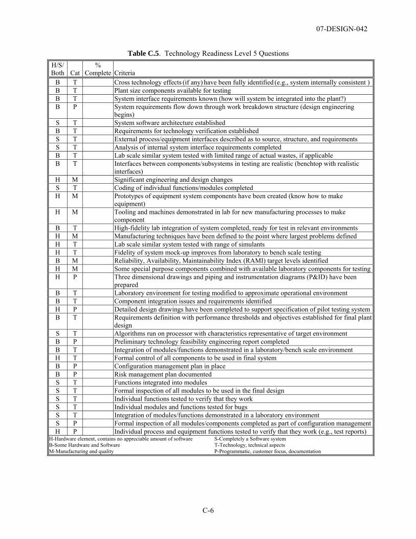
07-DESIGN-042
C-6
Table C.5. Technology Readiness Level 5 Questions H/S/ Both Cat
% Complete Criteria
B T Cross technology effects (if any) have been fully identified (e.g., system internally consistent )B T Plant size components available for testing B T System interface requirements known (how will system be integrated into the plant?) B P System requirements flow down through work breakdown structure (design engineering
begins) S T System software architecture established B T Requirements for technology verification established S T External process/equipment interfaces described as to source, structure, and requirements S T Analysis of internal system interface requirements completed B T Lab scale similar system tested with limited range of actual wastes, if applicable B T Interfaces between components/subsystems in testing are realistic (benchtop with realistic
interfaces) H M Significant engineering and design changes S T Coding of individual functions/modules completed H M Prototypes of equipment system components have been created (know how to make
equipment) H M Tooling and machines demonstrated in lab for new manufacturing processes to make
component B T High-fidelity lab integration of system completed, ready for test in relevant environments H M Manufacturing techniques have been defined to the point where largest problems defined H T Lab scale similar system tested with range of simulants H T Fidelity of system mock-up improves from laboratory to bench scale testing B M Reliability, Availability, Maintainability Index (RAMI) target levels identified H M Some special purpose components combined with available laboratory components for testingH P Three dimensional drawings and piping and instrumentation diagrams (P&ID) have been
prepared B T Laboratory environment for testing modified to approximate operational environment B T Component integration issues and requirements identified H P Detailed design drawings have been completed to support specification of pilot testing systemB T Requirements definition with performance thresholds and objectives established for final plant
design S T Algorithms run on processor with characteristics representative of target environment B P Preliminary technology feasibility engineering report completed B T Integration of modules/functions demonstrated in a laboratory/bench scale environment H T Formal control of all components to be used in final system B P Configuration management plan in place B P Risk management plan documented S T Functions integrated into modules S T Formal inspection of all modules to be used in the final design S T Individual functions tested to verify that they work S T Individual modules and functions tested for bugs S T Integration of modules/functions demonstrated in a laboratory environment S P Formal inspection of all modules/components completed as part of configuration managementH P Individual process and equipment functions tested to verify that they work (e.g., test reports)
H-Hardware element, contains no appreciable amount of software S-Completely a Software system B-Some Hardware and Software T-Technology, technical aspects M-Manufacturing and quality P-Programmatic, customer focus, documentation
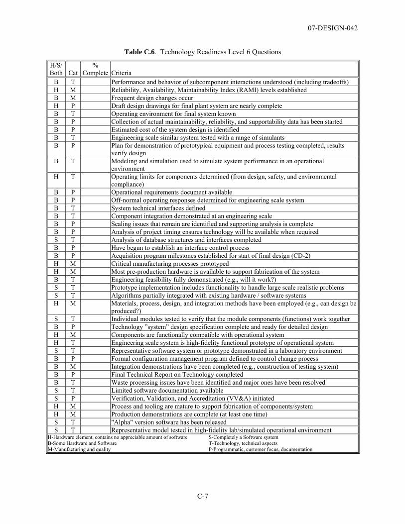
07-DESIGN-042
C-7
Table C.6. Technology Readiness Level 6 Questions
H/S/ Both Cat
% Complete Criteria
B T Performance and behavior of subcomponent interactions understood (including tradeoffs) H M Reliability, Availability, Maintainability Index (RAMI) levels established B M Frequent design changes occur H P Draft design drawings for final plant system are nearly complete B T Operating environment for final system known B P Collection of actual maintainability, reliability, and supportability data has been started B P Estimated cost of the system design is identified B T Engineering scale similar system tested with a range of simulants B P Plan for demonstration of prototypical equipment and process testing completed, results
verify design B T Modeling and simulation used to simulate system performance in an operational
environment H T Operating limits for components determined (from design, safety, and environmental
compliance) B P Operational requirements document available B P Off-normal operating responses determined for engineering scale system B T System technical interfaces defined B T Component integration demonstrated at an engineering scale B P Scaling issues that remain are identified and supporting analysis is complete B P Analysis of project timing ensures technology will be available when required S T Analysis of database structures and interfaces completed B P Have begun to establish an interface control process B P Acquisition program milestones established for start of final design (CD-2) H M Critical manufacturing processes prototyped H M Most pre-production hardware is available to support fabrication of the system B T Engineering feasibility fully demonstrated (e.g., will it work?) S T Prototype implementation includes functionality to handle large scale realistic problems S T Algorithms partially integrated with existing hardware / software systems H M Materials, process, design, and integration methods have been employed (e.g., can design be
produced?) S T Individual modules tested to verify that the module components (functions) work together B P Technology ”system” design specification complete and ready for detailed design H M Components are functionally compatible with operational system H T Engineering scale system is high-fidelity functional prototype of operational system S T Representative software system or prototype demonstrated in a laboratory environment B P Formal configuration management program defined to control change process B M Integration demonstrations have been completed (e.g., construction of testing system) B P Final Technical Report on Technology completed B T Waste processing issues have been identified and major ones have been resolved S T Limited software documentation available S P Verification, Validation, and Accreditation (VV&A) initiated H M Process and tooling are mature to support fabrication of components/system H M Production demonstrations are complete (at least one time) S T "Alpha" version software has been released S T Representative model tested in high-fidelity lab/simulated operational environment
H-Hardware element, contains no appreciable amount of software S-Completely a Software system B-Some Hardware and Software T-Technology, technical aspects M-Manufacturing and quality P-Programmatic, customer focus, documentation

07-DESIGN-042
Appendix D
Technology Readiness Level Summary for WTP Critical Technology Elements for LAB/BOF/LAW

07-DESIGN-042
D-1
Appendix D
Technology Readiness Level Summary for WTP Critical Technology Elements for LAB/BOF/LAW
Appendix D summarizes the responses to the specific criteria identified in level 6 of the Technology Readiness Level (TRL) Calculator (Appendix C) for all systems identified as critical technology elements (CTE). The ILAW Container Finishing Handling System (LFH) decontamination subsystem was the only CTE determined not to have attained TRL 5. Table D.4 contains the responses for TRL 5 for this system. Responses to questions that reflected the criterion that was not completed are shown in bold in the tables below. The following systems were evaluated.
• Table D.1 – Analytical Hot Cell Laboratory Equipment/ Analytical Radiological Laboratory Equipment Systems (AHL/ARL)
• Table D.2 – Autosampling System (ASX)
• Table D.3 – ILAW Container Finishing Handling System (LFH) container sealing subystem
• Table D.4 – ILAW Container Finishing Handling System (LFH) decontamination subsystem (TRL 5)
• Table D.5 – ILAW Container Finishing Handling System (LFH) decontamination subsystem (TRL 6)
• Table D.6 – LAW Melter Feed Process System (LFP)
• Table D.7 – LAW Melter Process System (LMP)
• Table D.8 – LAW Primary Offgas Process and Secondary Offgas Vessel Vent Process Systems (LOP/LVP)
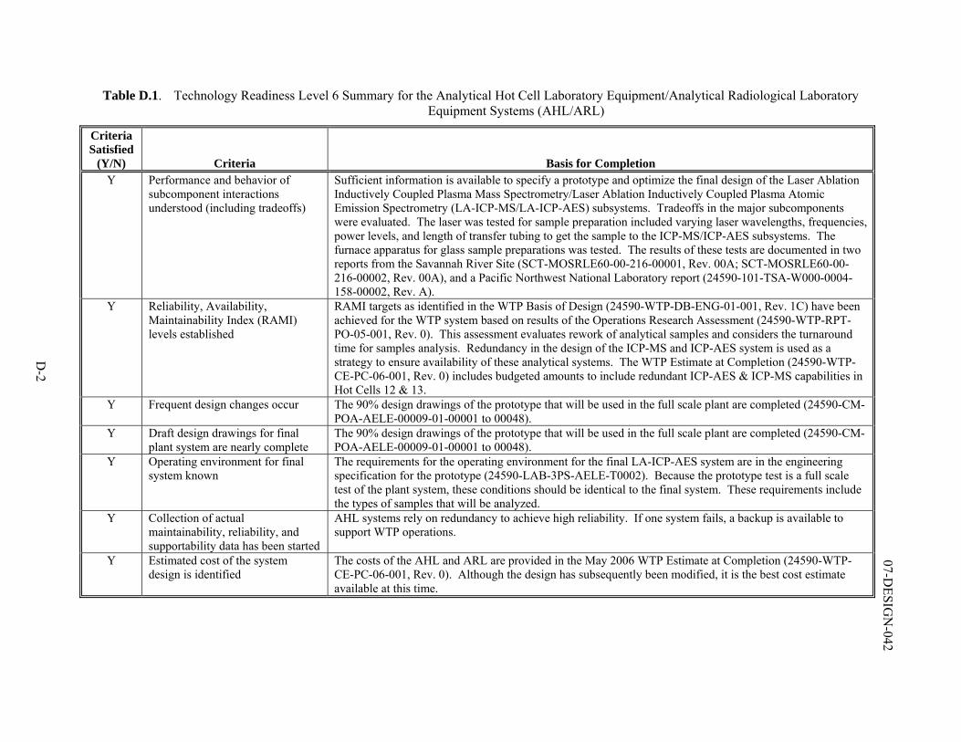
D-2
07-DESIG
N-042
Table D.1. Technology Readiness Level 6 Summary for the Analytical Hot Cell Laboratory Equipment/Analytical Radiological Laboratory Equipment Systems (AHL/ARL)
Criteria Satisfied
(Y/N) Criteria Basis for Completion Y Performance and behavior of
subcomponent interactions understood (including tradeoffs)
Sufficient information is available to specify a prototype and optimize the final design of the Laser Ablation Inductively Coupled Plasma Mass Spectrometry/Laser Ablation Inductively Coupled Plasma Atomic Emission Spectrometry (LA-ICP-MS/LA-ICP-AES) subsystems. Tradeoffs in the major subcomponents were evaluated. The laser was tested for sample preparation included varying laser wavelengths, frequencies, power levels, and length of transfer tubing to get the sample to the ICP-MS/ICP-AES subsystems. The furnace apparatus for glass sample preparations was tested. The results of these tests are documented in two reports from the Savannah River Site (SCT-MOSRLE60-00-216-00001, Rev. 00A; SCT-MOSRLE60-00-216-00002, Rev. 00A), and a Pacific Northwest National Laboratory report (24590-101-TSA-W000-0004-158-00002, Rev. A).
Y Reliability, Availability, Maintainability Index (RAMI) levels established
RAMI targets as identified in the WTP Basis of Design (24590-WTP-DB-ENG-01-001, Rev. 1C) have been achieved for the WTP system based on results of the Operations Research Assessment (24590-WTP-RPT-PO-05-001, Rev. 0). This assessment evaluates rework of analytical samples and considers the turnaround time for samples analysis. Redundancy in the design of the ICP-MS and ICP-AES system is used as a strategy to ensure availability of these analytical systems. The WTP Estimate at Completion (24590-WTP-CE-PC-06-001, Rev. 0) includes budgeted amounts to include redundant ICP-AES & ICP-MS capabilities in Hot Cells 12 & 13.
Y Frequent design changes occur The 90% design drawings of the prototype that will be used in the full scale plant are completed (24590-CM-POA-AELE-00009-01-00001 to 00048).
Y Draft design drawings for final plant system are nearly complete
The 90% design drawings of the prototype that will be used in the full scale plant are completed (24590-CM-POA-AELE-00009-01-00001 to 00048).
Y Operating environment for final system known
The requirements for the operating environment for the final LA-ICP-AES system are in the engineering specification for the prototype (24590-LAB-3PS-AELE-T0002). Because the prototype test is a full scale test of the plant system, these conditions should be identical to the final system. These requirements include the types of samples that will be analyzed.
Y Collection of actual maintainability, reliability, and supportability data has been started
AHL systems rely on redundancy to achieve high reliability. If one system fails, a backup is available to support WTP operations.
Y Estimated cost of the system design is identified
The costs of the AHL and ARL are provided in the May 2006 WTP Estimate at Completion (24590-WTP-CE-PC-06-001, Rev. 0). Although the design has subsequently been modified, it is the best cost estimate available at this time.
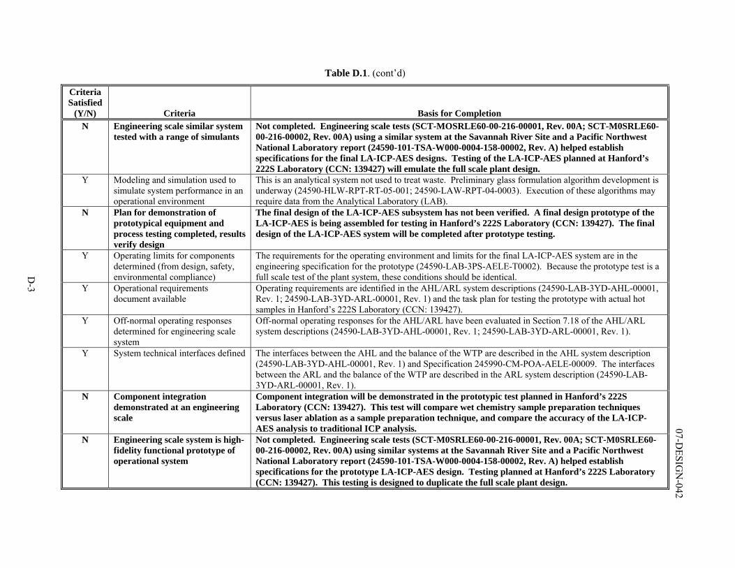
D-3
07-DESIG
N-042
Table D.1. (cont’d)
Criteria Satisfied
(Y/N) Criteria Basis for Completion N Engineering scale similar system
tested with a range of simulants Not completed. Engineering scale tests (SCT-MOSRLE60-00-216-00001, Rev. 00A; SCT-M0SRLE60-00-216-00002, Rev. 00A) using a similar system at the Savannah River Site and a Pacific Northwest National Laboratory report (24590-101-TSA-W000-0004-158-00002, Rev. A) helped establish specifications for the final LA-ICP-AES designs. Testing of the LA-ICP-AES planned at Hanford’s 222S Laboratory (CCN: 139427) will emulate the full scale plant design.
Y Modeling and simulation used to simulate system performance in an operational environment
This is an analytical system not used to treat waste. Preliminary glass formulation algorithm development is underway (24590-HLW-RPT-RT-05-001; 24590-LAW-RPT-04-0003). Execution of these algorithms may require data from the Analytical Laboratory (LAB).
N Plan for demonstration of prototypical equipment and process testing completed, results verify design
The final design of the LA-ICP-AES subsystem has not been verified. A final design prototype of the LA-ICP-AES is being assembled for testing in Hanford’s 222S Laboratory (CCN: 139427). The final design of the LA-ICP-AES system will be completed after prototype testing.
Y Operating limits for components determined (from design, safety, environmental compliance)
The requirements for the operating environment and limits for the final LA-ICP-AES system are in the engineering specification for the prototype (24590-LAB-3PS-AELE-T0002). Because the prototype test is a full scale test of the plant system, these conditions should be identical.
Y Operational requirements document available
Operating requirements are identified in the AHL/ARL system descriptions (24590-LAB-3YD-AHL-00001, Rev. 1; 24590-LAB-3YD-ARL-00001, Rev. 1) and the task plan for testing the prototype with actual hot samples in Hanford’s 222S Laboratory (CCN: 139427).
Y Off-normal operating responses determined for engineering scale system
Off-normal operating responses for the AHL/ARL have been evaluated in Section 7.18 of the AHL/ARL system descriptions (24590-LAB-3YD-AHL-00001, Rev. 1; 24590-LAB-3YD-ARL-00001, Rev. 1).
Y System technical interfaces defined The interfaces between the AHL and the balance of the WTP are described in the AHL system description (24590-LAB-3YD-AHL-00001, Rev. 1) and Specification 245990-CM-POA-AELE-00009. The interfaces between the ARL and the balance of the WTP are described in the ARL system description (24590-LAB-3YD-ARL-00001, Rev. 1).
N Component integration demonstrated at an engineering scale
Component integration will be demonstrated in the prototypic test planned in Hanford’s 222S Laboratory (CCN: 139427). This test will compare wet chemistry sample preparation techniques versus laser ablation as a sample preparation technique, and compare the accuracy of the LA-ICP-AES analysis to traditional ICP analysis.
N Engineering scale system is high-fidelity functional prototype of operational system
Not completed. Engineering scale tests (SCT-M0SRLE60-00-216-00001, Rev. 00A; SCT-M0SRLE60-00-216-00002, Rev. 00A) using similar systems at the Savannah River Site and a Pacific Northwest National Laboratory report (24590-101-TSA-W000-0004-158-00002, Rev. A) helped establish specifications for the prototype LA-ICP-AES design. Testing planned at Hanford’s 222S Laboratory (CCN: 139427). This testing is designed to duplicate the full scale plant design.
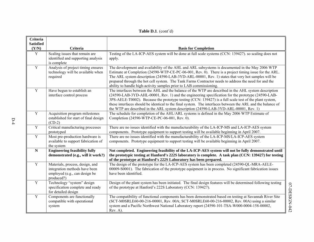
D-4
07-DESIG
N-042
Table D.1. (cont’d)
Criteria Satisfied
(Y/N) Criteria Basis for Completion Y Scaling issues that remain are
identified and supporting analysis is complete
Testing of the LA-ICP-AES system will be done at full scale systems (CCN: 139427). so scaling does not apply.
Y Analysis of project timing ensures technology will be available when required
The development and availability of the AHL and ARL subsystems is documented in the May 2006 WTP Estimate at Completion (24590-WTP-CE-PC-06-001, Rev. 0). There is a project timing issue for the ARL. The ARL system description (24590-LAB-3YD-ARL-00001, Rev. 1) states that very hot samples will be prepared through the hot cell system. The Tank Farms Contractor needs to address the need for and the ability to handle high-activity samples prior to LAB commissioning.
Y Have begun to establish an interface control process
The interfaces between the AHL and the balance of the WTP are described in the AHL system description (24590-LAB-3YD-AHL-00001, Rev. 1) and the engineering specification for the prototype (24590-LAB-3PS-AELE-T0002). Because the prototype testing (CCN: 139427) is a full scale test of the plant system, these interfaces should be identical to the final system. The interfaces between the ARL and the balance of the WTP are described in the ARL system description (24590-LAB-3YD-ARL-00001, Rev. 1)
Y Acquisition program milestones established for start of final design (CD-2)
The schedule for completion of the AHL/ARL systems is defined in the May 2006 WTP Estimate of Completion (24590-WTP-CE-PC-06-001, Rev. 0).
Y Critical manufacturing processes prototyped
There are no issues identified with the manufacturability of the LA-ICP-MS and LA-ICP-AES system components. Prototype equipment to support testing will be available beginning in April 2007.
Y Most pre-production hardware is available to support fabrication of the system
There are no issues identified with the manufacturability of the LA-ICP-MS/LA-ICP-AES system components. Prototype equipment to support testing will be available beginning in April 2007.
N Engineering feasibility fully demonstrated (e.g., will it work?)
Not completed. Engineering feasibility of the LA-ICP-AES system will not be fully demonstrated until the prototypic testing at Hanford’s 222S laboratory is complete. A task plan (CCN: 139427) for testing of the prototype at Hanford’s 222S Laboratory has been prepared.
Y Materials, process, design, and integration methods have been employed (e.g., can design be produced?)
The design of the prototype for the LA-ICP-AES system has been completed (24590-QL-MRA-AELE-00009-S0001). The fabrication of the prototype equipment is in process. No significant fabrication issues have been identified.
Y Technology “system” design specification complete and ready for detailed design
Design of the plant system has been initiated. The final design features will be determined following testing of the prototype at Hanford’s 222S Laboratory (CCN: 139427).
Y Components are functionally compatible with operational system
The compatibility of functional components has been demonstrated based on testing at Savannah River Site (SCT-M0SRLE60-00-216-00001, Rev. 00A; SCT-M0SRLE60-00-216-00002, Rev. 00A) using a similar system and a Pacific Northwest National Laboratory report (24590-101-TSA-W000-0004-158-00002, Rev. A).
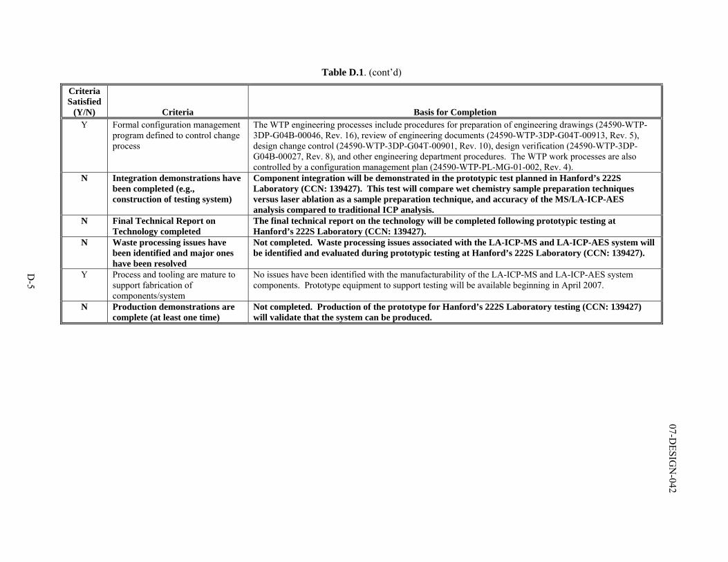
D-5
07-DESIG
N-042
Table D.1. (cont’d)
Criteria Satisfied
(Y/N) Criteria Basis for Completion Y Formal configuration management
program defined to control change process
The WTP engineering processes include procedures for preparation of engineering drawings (24590-WTP-3DP-G04B-00046, Rev. 16), review of engineering documents (24590-WTP-3DP-G04T-00913, Rev. 5), design change control (24590-WTP-3DP-G04T-00901, Rev. 10), design verification (24590-WTP-3DP-G04B-00027, Rev. 8), and other engineering department procedures. The WTP work processes are also controlled by a configuration management plan (24590-WTP-PL-MG-01-002, Rev. 4).
N Integration demonstrations have been completed (e.g., construction of testing system)
Component integration will be demonstrated in the prototypic test planned in Hanford’s 222S Laboratory (CCN: 139427). This test will compare wet chemistry sample preparation techniques versus laser ablation as a sample preparation technique, and accuracy of the MS/LA-ICP-AES analysis compared to traditional ICP analysis.
N Final Technical Report on Technology completed
The final technical report on the technology will be completed following prototypic testing at Hanford’s 222S Laboratory (CCN: 139427).
N Waste processing issues have been identified and major ones have been resolved
Not completed. Waste processing issues associated with the LA-ICP-MS and LA-ICP-AES system will be identified and evaluated during prototypic testing at Hanford’s 222S Laboratory (CCN: 139427).
Y Process and tooling are mature to support fabrication of components/system
No issues have been identified with the manufacturability of the LA-ICP-MS and LA-ICP-AES system components. Prototype equipment to support testing will be available beginning in April 2007.
N Production demonstrations are complete (at least one time)
Not completed. Production of the prototype for Hanford’s 222S Laboratory testing (CCN: 139427) will validate that the system can be produced.
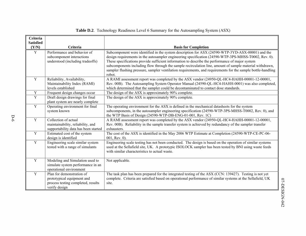
D-6
07-DESIG
N-042
Table D.2. Technology Readiness Level 6 Summary for the Autosampling System (ASX)
Criteria Satisfied
(Y/N) Criteria Basis for Completion Y Performance and behavior of
subcomponent interactions understood (including tradeoffs)
Subcomponent were identified in the system description for ASX (24590-WTP-3YD-ASX-00001) and the design requirements in the autosampler engineering specification (24590-WTP-3PS-MHSS-T0002, Rev. 0). These specifications provide sufficient information to describe the performance of major system subcomponents including flow through the sample recirculation line, amount of sample material withdrawn, sampler flushing pressure, sampler ventilation requirements, and requirements for the sample bottle-handling robot.
Y Reliability, Availability, Maintainability Index (RAMI) levels established
A RAMI assessment report was completed by the ASX vendor (24950-QL-HC4-HAHH-00001-12-00001, Rev. 00B). The Autosampling System Operator Manual (24590-QL-HC4-HAHH-0001) was also completed, which determined that the sampler could be decontaminated to contact dose standards.
Y Frequent design changes occur The design of the ASX is approximately 90% complete. Y Draft design drawings for final
plant system are nearly complete The design of the ASX is approximately 90% complete.
Y Operating environment for final system known
The operating environment for the ASX is defined in the mechanical datasheets for the system subcomponents, in the autosampler engineering specification (24590-WTP-3PS-MHSS-T0002, Rev. 0), and the WTP Basis of Design (24590-WTP-DB-ENG-01-001, Rev. 1C)
Y Collection of actual maintainability, reliability, and supportability data has been started
A RAMI assessment report was completed by the ASX vendor (24950-QL-HC4-HAHH-00001-12-00001, Rev. 00B). Reliability in the sample transfer system is achieved by redundancy of the sampler transfer exhausters.
Y Estimated cost of the system design is identified
The cost of the ASX is identified in the May 2006 WTP Estimate at Completion (24590-WTP-CE-PC-06-001, Rev. 0).
Y Engineering scale similar system tested with a range of simulants
Engineering scale testing has not been conducted. The design is based on the operation of similar systems used at the Sellafield site, UK. A prototypic ISOLOCK sampler has been tested by BNI using waste feeds with similar characteristics to actual waste.
Y Modeling and Simulation used to simulate system performance in an operational environment
Not applicable.
Y Plan for demonstration of prototypical equipment and process testing completed, results verify design
The task plan has been prepared for the integrated testing of the ASX (CCN: 139427). Testing is not yet complete. Criteria are satisfied based on operational performance of similar systems at the Sellafield, UK site.
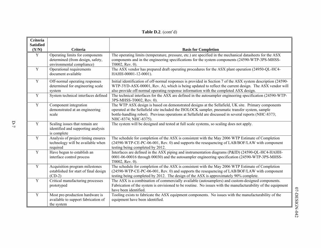
D-7
07-DESIG
N-042
Table D.2. (cont’d)
Criteria Satisfied
(Y/N) Criteria Basis for Completion Y Operating limits for components
determined (from design, safety, environmental compliance)
The operating limits (temperature, pressure, etc.) are specified in the mechanical datasheets for the ASX components and in the engineering specifications for the system components (24590-WTP-3PS-MHSS-T0002, Rev. 0).
Y Operational requirements document available
The ASX vendor has prepared draft operating procedures for the ASX plant operation (24950-QL-HC4-HAHH-00001-12-0001).
Y Off-normal operating responses determined for engineering scale system
Initial identification of off-normal responses is provided in Section 7 of the ASX system description (24590-WTP-3YD-ASX-00001, Rev. A), which is being updated to reflect the current design. The ASX vendor will also provide off-normal operating response information with the completed ASX design.
Y System technical interfaces defined The technical interfaces for the ASX are defined in the autosampler engineering specification (24590-WTP-3PS-MHSS-T0002, Rev. 0).
Y Component integration demonstrated at an engineering scale
The WTP ASX design is based on demonstrated designs at the Sellafield, UK site. Primary components operated at the Sellafield site included the ISOLOCK sampler, pneumatic transfer system, sample bottle-handling robot). Previous operations at Sellafield are discussed in several reports (NHC-8373; NHC-8374; NHC-8375).
Y Scaling issues that remain are identified and supporting analysis is complete
The system will be designed and tested at full scale systems, so scaling does not apply.
Y Analysis of project timing ensures technology will be available when required
The schedule for completion of the ASX is consistent with the May 2006 WTP Estimate of Completion (24590-WTP-CE-PC-06-001, Rev. 0) and supports the resequencing of LAB/BOF/LAW with component testing being completed by 2012.
Y Have begun to establish an interface control process
Interfaces are defined in the ASX piping and instrumentation diagrams (P&ID) (24590-QL-HC4-HAHH-0001-06-00016 through 00030) and the autosampler engineering specification (24590-WTP-3PS-MHSS-T0002, Rev. 0).
Y Acquisition program milestones established for start of final design (CD-2)
The schedule for completion of the ASX is consistent with the May 2006 WTP Estimate of Completion (24590-WTP-CE-PC-06-001, Rev. 0) and supports the resequencing of LAB/BOF/LAW with component testing being completed by 2012. The design of the ASX is approximately 90% complete.
Y Critical manufacturing processes prototyped
The ASX is a combination of commercially available (autosamplers) and custom-designed components. Fabrication of the system is envisioned to be routine. No issues with the manufacturability of the equipment have been identified.
Y Most pre-production hardware is available to support fabrication of the system
Tooling exists to fabricate the ASX equipment components. No issues with the manufacturability of the equipment have been identified.
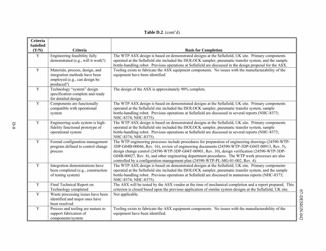
D-8
07-DESIG
N-042
Table D.2. (cont’d)
Criteria Satisfied
(Y/N) Criteria Basis for Completion Y Engineering feasibility fully
demonstrated (e.g., will it work?) The WTP ASX design is based on demonstrated designs at the Sellafield, UK site. Primary components operated at the Sellafield site included the ISOLOCK sampler, pneumatic transfer system, and the sample bottle-handling robot. Previous operations at Sellafield are discussed in the design proposal for the ASX.
Y Materials, process, design, and integration methods have been employed (e.g., can design be produced?)
Tooling exists to fabricate the ASX equipment components. No issues with the manufacturability of the equipment have been identified
Y Technology “system” design specification complete and ready for detailed design
The design of the ASX is approximately 90% complete.
Y Components are functionally compatible with operational system
The WTP ASX design is based on demonstrated designs at the Sellafield, UK site. Primary components operated at the Sellafield site included the ISOLOCK sampler, pneumatic transfer system, sample bottle-handling robot. Previous operations at Sellafield are discussed in several reports (NHC-8373; NHC-8374; NHC-8375).
Y Engineering scale system is high-fidelity functional prototype of operational system
The WTP ASX design is based on demonstrated designs at the Sellafield, UK site. Primary components operated at the Sellafield site included the ISOLOCK sampler, pneumatic transfer system, sample bottle-handling robot. Previous operations at Sellafield are discussed in several reports (NHC-8373; NHC-8374; NHC-8375).
Y Formal configuration management program defined to control change process
The WTP engineering processes include procedures for preparation of engineering drawings (24590-WTP-3DP-G04B-00046, Rev. 16), review of engineering documents (24590-WTP-3DP-G04T-00913, Rev. 5), design change control (24590-WTP-3DP-G04T-00901, Rev. 10), design verification (24590-WTP-3DP-G04B-00027, Rev. 8), and other engineering department procedures. The WTP work processes are also controlled by a configuration management plan (24590-WTP-PL-MG-01-002, Rev. 4).
Y Integration demonstrations have been completed (e.g., construction of testing system)
The WTP ASX design is based on demonstrated designs at the Sellafield, UK site. Primary components operated at the Sellafield site included the ISOLOCK sampler, pneumatic transfer system, and the sample bottle-handling robot. Previous operations at Sellafield are discussed in numerous reports (NHC-8373; NHC-8374; NHC-8375).
Y Final Technical Report on Technology completed
The ASX will be tested by the ASX vendor at the time of mechanical completion and a report prepared. This criterion is closed based upon the previous application of similar system designs at the Sellafield, UK site.
Y Waste processing issues have been identified and major ones have been resolved
Not applicable.
Y Process and tooling are mature to support fabrication of components/system
Tooling exists to fabricate the ASX equipment components. No issues with the manufacturability of the equipment have been identified.
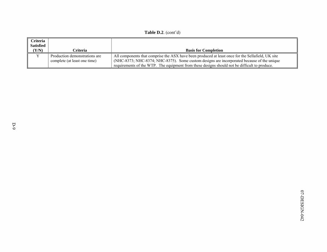
D-9
07-DESIG
N-042
Table D.2. (cont’d)
Criteria Satisfied
(Y/N) Criteria Basis for Completion Y Production demonstrations are
complete (at least one time) All components that comprise the ASX have been produced at least once for the Sellafield, UK site (NHC-8373; NHC-8374; NHC-8375). Some custom designs are incorporated because of the unique requirements of the WTP. The equipment from these designs should not be difficult to produce.
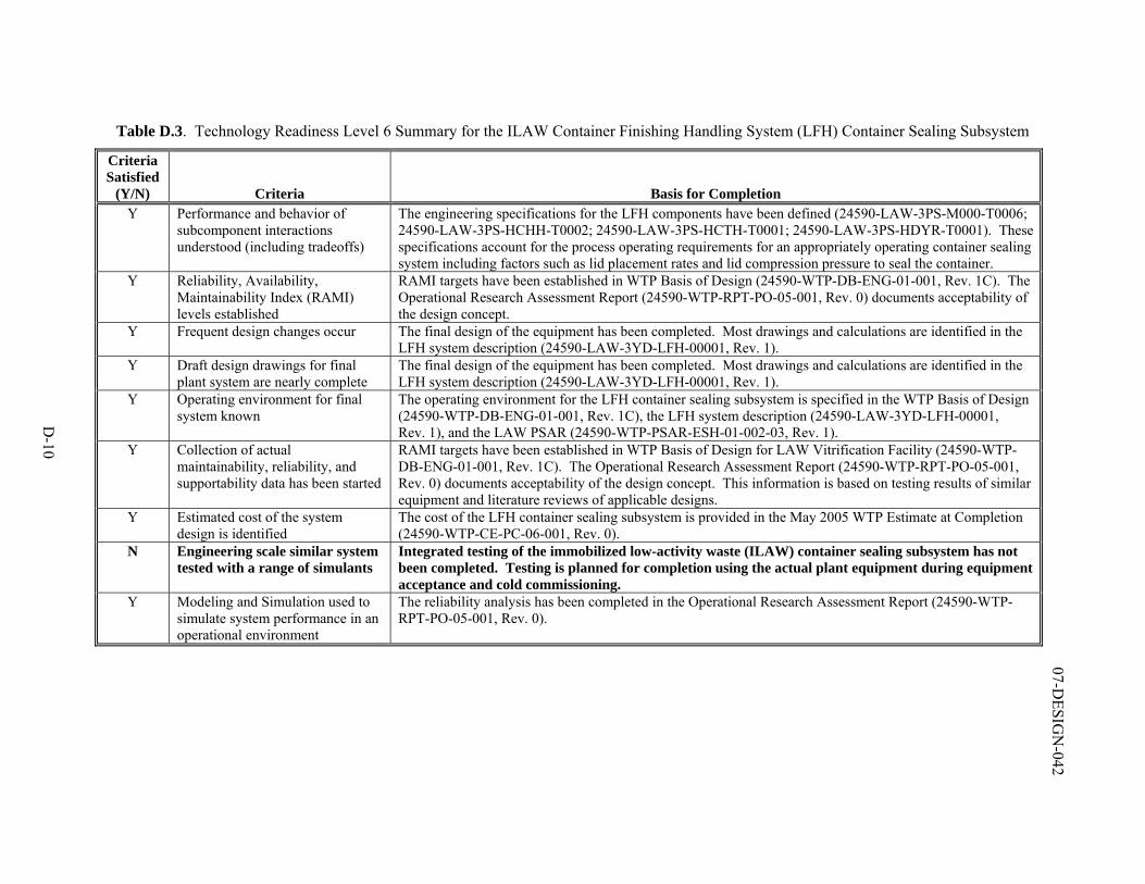
D-10
07-DESIG
N-042
Table D.3. Technology Readiness Level 6 Summary for the ILAW Container Finishing Handling System (LFH) Container Sealing Subsystem
Criteria Satisfied
(Y/N) Criteria Basis for Completion Y Performance and behavior of
subcomponent interactions understood (including tradeoffs)
The engineering specifications for the LFH components have been defined (24590-LAW-3PS-M000-T0006; 24590-LAW-3PS-HCHH-T0002; 24590-LAW-3PS-HCTH-T0001; 24590-LAW-3PS-HDYR-T0001). These specifications account for the process operating requirements for an appropriately operating container sealing system including factors such as lid placement rates and lid compression pressure to seal the container.
Y Reliability, Availability, Maintainability Index (RAMI) levels established
RAMI targets have been established in WTP Basis of Design (24590-WTP-DB-ENG-01-001, Rev. 1C). The Operational Research Assessment Report (24590-WTP-RPT-PO-05-001, Rev. 0) documents acceptability of the design concept.
Y Frequent design changes occur The final design of the equipment has been completed. Most drawings and calculations are identified in the LFH system description (24590-LAW-3YD-LFH-00001, Rev. 1).
Y Draft design drawings for final plant system are nearly complete
The final design of the equipment has been completed. Most drawings and calculations are identified in the LFH system description (24590-LAW-3YD-LFH-00001, Rev. 1).
Y Operating environment for final system known
The operating environment for the LFH container sealing subsystem is specified in the WTP Basis of Design (24590-WTP-DB-ENG-01-001, Rev. 1C), the LFH system description (24590-LAW-3YD-LFH-00001, Rev. 1), and the LAW PSAR (24590-WTP-PSAR-ESH-01-002-03, Rev. 1).
Y Collection of actual maintainability, reliability, and supportability data has been started
RAMI targets have been established in WTP Basis of Design for LAW Vitrification Facility (24590-WTP-DB-ENG-01-001, Rev. 1C). The Operational Research Assessment Report (24590-WTP-RPT-PO-05-001, Rev. 0) documents acceptability of the design concept. This information is based on testing results of similar equipment and literature reviews of applicable designs.
Y Estimated cost of the system design is identified
The cost of the LFH container sealing subsystem is provided in the May 2005 WTP Estimate at Completion (24590-WTP-CE-PC-06-001, Rev. 0).
N Engineering scale similar system tested with a range of simulants
Integrated testing of the immobilized low-activity waste (ILAW) container sealing subsystem has not been completed. Testing is planned for completion using the actual plant equipment during equipment acceptance and cold commissioning.
Y Modeling and Simulation used to simulate system performance in an operational environment
The reliability analysis has been completed in the Operational Research Assessment Report (24590-WTP-RPT-PO-05-001, Rev. 0).
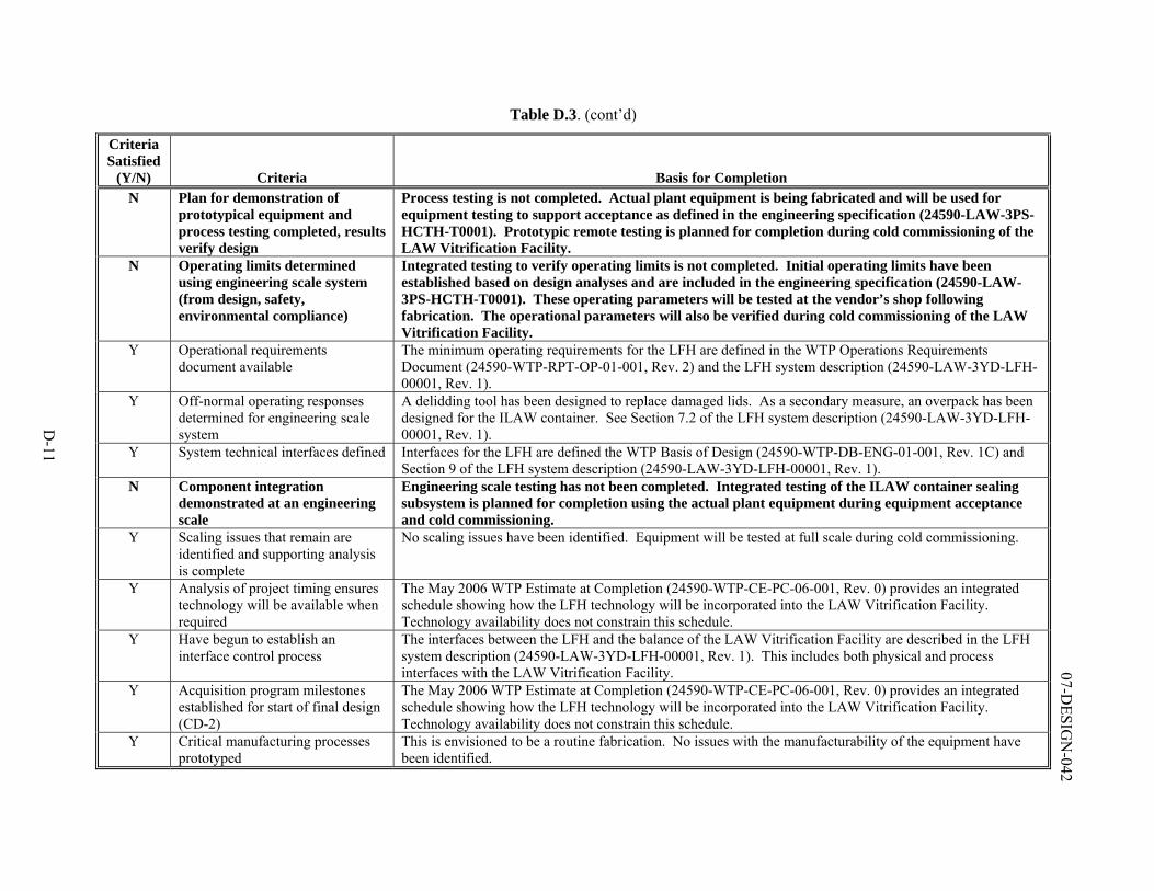
D-11
07-DESIG
N-042
Table D.3. (cont’d)
Criteria Satisfied
(Y/N) Criteria Basis for Completion N Plan for demonstration of
prototypical equipment and process testing completed, results verify design
Process testing is not completed. Actual plant equipment is being fabricated and will be used for equipment testing to support acceptance as defined in the engineering specification (24590-LAW-3PS-HCTH-T0001). Prototypic remote testing is planned for completion during cold commissioning of the LAW Vitrification Facility.
N Operating limits determined using engineering scale system (from design, safety, environmental compliance)
Integrated testing to verify operating limits is not completed. Initial operating limits have been established based on design analyses and are included in the engineering specification (24590-LAW-3PS-HCTH-T0001). These operating parameters will be tested at the vendor’s shop following fabrication. The operational parameters will also be verified during cold commissioning of the LAW Vitrification Facility.
Y Operational requirements document available
The minimum operating requirements for the LFH are defined in the WTP Operations Requirements Document (24590-WTP-RPT-OP-01-001, Rev. 2) and the LFH system description (24590-LAW-3YD-LFH-00001, Rev. 1).
Y Off-normal operating responses determined for engineering scale system
A delidding tool has been designed to replace damaged lids. As a secondary measure, an overpack has been designed for the ILAW container. See Section 7.2 of the LFH system description (24590-LAW-3YD-LFH-00001, Rev. 1).
Y System technical interfaces defined Interfaces for the LFH are defined the WTP Basis of Design (24590-WTP-DB-ENG-01-001, Rev. 1C) and Section 9 of the LFH system description (24590-LAW-3YD-LFH-00001, Rev. 1).
N Component integration demonstrated at an engineering scale
Engineering scale testing has not been completed. Integrated testing of the ILAW container sealing subsystem is planned for completion using the actual plant equipment during equipment acceptance and cold commissioning.
Y Scaling issues that remain are identified and supporting analysis is complete
No scaling issues have been identified. Equipment will be tested at full scale during cold commissioning.
Y Analysis of project timing ensures technology will be available when required
The May 2006 WTP Estimate at Completion (24590-WTP-CE-PC-06-001, Rev. 0) provides an integrated schedule showing how the LFH technology will be incorporated into the LAW Vitrification Facility. Technology availability does not constrain this schedule.
Y Have begun to establish an interface control process
The interfaces between the LFH and the balance of the LAW Vitrification Facility are described in the LFH system description (24590-LAW-3YD-LFH-00001, Rev. 1). This includes both physical and process interfaces with the LAW Vitrification Facility.
Y Acquisition program milestones established for start of final design (CD-2)
The May 2006 WTP Estimate at Completion (24590-WTP-CE-PC-06-001, Rev. 0) provides an integrated schedule showing how the LFH technology will be incorporated into the LAW Vitrification Facility. Technology availability does not constrain this schedule.
Y Critical manufacturing processes prototyped
This is envisioned to be a routine fabrication. No issues with the manufacturability of the equipment have been identified.
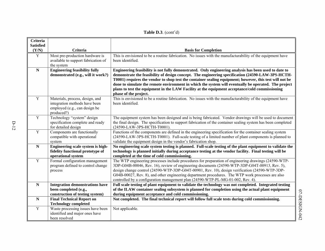
D-12
07-DESIG
N-042
Table D.3. (cont’d)
Criteria Satisfied
(Y/N) Criteria Basis for Completion Y Most pre-production hardware is
available to support fabrication of the system
This is envisioned to be a routine fabrication. No issues with the manufacturability of the equipment have been identified.
N Engineering feasibility fully demonstrated (e.g., will it work?)
Engineering feasibility is not fully demonstrated. Only engineering analysis has been used to date to demonstrate the feasibility of design concept. The engineering specification (24590-LAW-3PS-HCTH-T0001) requires the vendor to shop test the container sealing equipment; however, this test will not be done to simulate the remote environment in which the system will eventually be operated. The project plans to test the equipment in the LAW Facility at the equipment acceptance/cold commissioning phase of the project.
Y Materials, process, design, and integration methods have been employed (e.g., can design be produced?)
This is envisioned to be a routine fabrication. No issues with the manufacturability of the equipment have been identified.
Y Technology “system” design specification complete and ready for detailed design
The equipment system has been designed and is being fabricated. Vendor drawings will be used to document the final design. The specification to support fabrication of the container sealing system has been completed (24590-LAW-3PS-HCTH-T0001).
Y Components are functionally compatible with operational system
Functions of the components are defined in the engineering specification for the container sealing system (24590-LAW-3PS-HCTH-T0001). Full-scale testing of a limited number of plant components is planned to validate the equipment design in the vendor’s fabrication shop.
N Engineering scale system is high-fidelity functional prototype of operational system
No engineering scale system testing is planned. Full-scale testing of the plant equipment to validate the technology is planned initially during acceptance testing at the vendor facility. Final testing will be completed at the time of cold commissioning.
Y Formal configuration management program defined to control change process
The WTP engineering processes include procedures for preparation of engineering drawings (24590-WTP-3DP-G04B-00046, Rev. 16), review of engineering documents (24590-WTP-3DP-G04T-00913, Rev. 5), design change control (24590-WTP-3DP-G04T-00901, Rev. 10), design verification (24590-WTP-3DP-G04B-00027, Rev. 8), and other engineering department procedures. The WTP work processes are also controlled by a configuration management plan (24590-WTP-PL-MG-01-002, Rev. 4).
N Integration demonstrations have been completed (e.g., construction of testing system)
Full scale testing of plant equipment to validate the technology was not completed. Integrated testing of the ILAW container sealing subsystem is planned for completion using the actual plant equipment during equipment acceptance and cold commissioning.
N Final Technical Report on Technology completed
Not completed. The final technical report will follow full scale tests during cold commissioning.
Y Waste processing issues have been identified and major ones have been resolved
Not applicable.
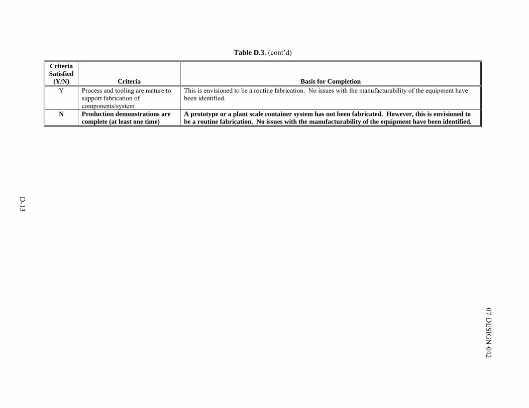
D-13
07-DESIG
N-042
Table D.3. (cont’d)
Criteria Satisfied
(Y/N) Criteria Basis for Completion Y Process and tooling are mature to
support fabrication of components/system
This is envisioned to be a routine fabrication. No issues with the manufacturability of the equipment have been identified.
N Production demonstrations are complete (at least one time)
A prototype or a plant scale container system has not been fabricated. However, this is envisioned to be a routine fabrication. No issues with the manufacturability of the equipment have been identified.
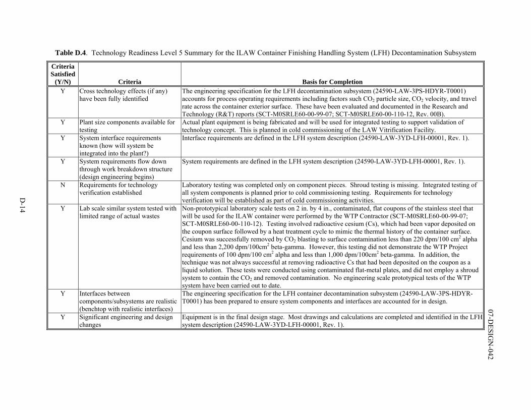
D-14
07-DESIG
N-042
Table D.4. Technology Readiness Level 5 Summary for the ILAW Container Finishing Handling System (LFH) Decontamination Subsystem
Criteria Satisfied
(Y/N) Criteria Basis for Completion Y Cross technology effects (if any)
have been fully identified The engineering specification for the LFH decontamination subsystem (24590-LAW-3PS-HDYR-T0001) accounts for process operating requirements including factors such CO2 particle size, CO2 velocity, and travel rate across the container exterior surface. These have been evaluated and documented in the Research and Technology (R&T) reports (SCT-M0SRLE60-00-99-07; SCT-M0SRLE60-00-110-12, Rev. 00B).
Y Plant size components available for testing
Actual plant equipment is being fabricated and will be used for integrated testing to support validation of technology concept. This is planned in cold commissioning of the LAW Vitrification Facility.
Y System interface requirements known (how will system be integrated into the plant?)
Interface requirements are defined in the LFH system description (24590-LAW-3YD-LFH-00001, Rev. 1).
Y System requirements flow down through work breakdown structure (design engineering begins)
System requirements are defined in the LFH system description (24590-LAW-3YD-LFH-00001, Rev. 1).
N Requirements for technology verification established
Laboratory testing was completed only on component pieces. Shroud testing is missing. Integrated testing of all system components is planned prior to cold commissioning testing. Requirements for technology verification will be established as part of cold commissioning activities.
Y Lab scale similar system tested with limited range of actual wastes
Non-prototypical laboratory scale tests on 2 in. by 4 in., contaminated, flat coupons of the stainless steel that will be used for the ILAW container were performed by the WTP Contractor (SCT-M0SRLE60-00-99-07; SCT-M0SRLE60-00-110-12). Testing involved radioactive cesium (Cs), which had been vapor deposited on the coupon surface followed by a heat treatment cycle to mimic the thermal history of the container surface. Cesium was successfully removed by CO2 blasting to surface contamination less than 220 dpm/100 cm2 alpha and less than 2,200 dpm/100cm2 beta-gamma. However, this testing did not demonstrate the WTP Project requirements of 100 dpm/100 cm2 alpha and less than 1,000 dpm/100cm2 beta-gamma. In addition, the technique was not always successful at removing radioactive Cs that had been deposited on the coupon as a liquid solution. These tests were conducted using contaminated flat-metal plates, and did not employ a shroud system to contain the CO2 and removed contamination. No engineering scale prototypical tests of the WTP system have been carried out to date.
Y Interfaces between components/subsystems are realistic (benchtop with realistic interfaces)
The engineering specification for the LFH container decontamination subsystem (24590-LAW-3PS-HDYR-T0001) has been prepared to ensure system components and interfaces are accounted for in design.
Y Significant engineering and design changes
Equipment is in the final design stage. Most drawings and calculations are completed and identified in the LFH system description (24590-LAW-3YD-LFH-00001, Rev. 1).
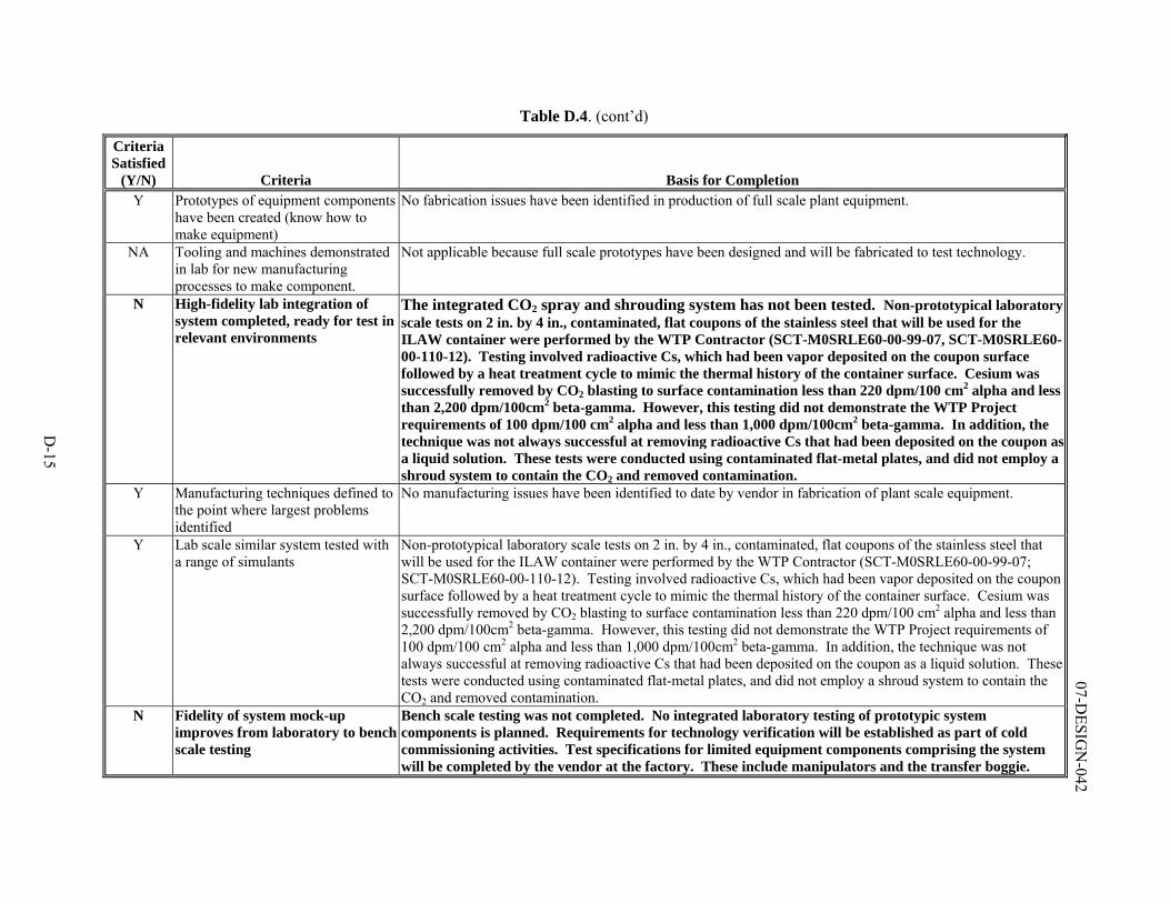
D-15
07-DESIG
N-042
Table D.4. (cont’d)
Criteria Satisfied
(Y/N) Criteria Basis for Completion Y Prototypes of equipment components
have been created (know how to make equipment)
No fabrication issues have been identified in production of full scale plant equipment.
NA Tooling and machines demonstrated in lab for new manufacturing processes to make component.
Not applicable because full scale prototypes have been designed and will be fabricated to test technology.
N High-fidelity lab integration of system completed, ready for test in relevant environments
The integrated CO2 spray and shrouding system has not been tested. Non-prototypical laboratory scale tests on 2 in. by 4 in., contaminated, flat coupons of the stainless steel that will be used for the ILAW container were performed by the WTP Contractor (SCT-M0SRLE60-00-99-07, SCT-M0SRLE60-00-110-12). Testing involved radioactive Cs, which had been vapor deposited on the coupon surface followed by a heat treatment cycle to mimic the thermal history of the container surface. Cesium was successfully removed by CO2 blasting to surface contamination less than 220 dpm/100 cm2 alpha and less than 2,200 dpm/100cm2 beta-gamma. However, this testing did not demonstrate the WTP Project requirements of 100 dpm/100 cm2 alpha and less than 1,000 dpm/100cm2 beta-gamma. In addition, the technique was not always successful at removing radioactive Cs that had been deposited on the coupon as a liquid solution. These tests were conducted using contaminated flat-metal plates, and did not employ a shroud system to contain the CO2 and removed contamination.
Y Manufacturing techniques defined to the point where largest problems identified
No manufacturing issues have been identified to date by vendor in fabrication of plant scale equipment.
Y Lab scale similar system tested with a range of simulants
Non-prototypical laboratory scale tests on 2 in. by 4 in., contaminated, flat coupons of the stainless steel that will be used for the ILAW container were performed by the WTP Contractor (SCT-M0SRLE60-00-99-07; SCT-M0SRLE60-00-110-12). Testing involved radioactive Cs, which had been vapor deposited on the coupon surface followed by a heat treatment cycle to mimic the thermal history of the container surface. Cesium was successfully removed by CO2 blasting to surface contamination less than 220 dpm/100 cm2 alpha and less than 2,200 dpm/100cm2 beta-gamma. However, this testing did not demonstrate the WTP Project requirements of 100 dpm/100 cm2 alpha and less than 1,000 dpm/100cm2 beta-gamma. In addition, the technique was not always successful at removing radioactive Cs that had been deposited on the coupon as a liquid solution. These tests were conducted using contaminated flat-metal plates, and did not employ a shroud system to contain the CO2 and removed contamination.
N Fidelity of system mock-up improves from laboratory to benchscale testing
Bench scale testing was not completed. No integrated laboratory testing of prototypic system components is planned. Requirements for technology verification will be established as part of cold commissioning activities. Test specifications for limited equipment components comprising the system will be completed by the vendor at the factory. These include manipulators and the transfer boggie.
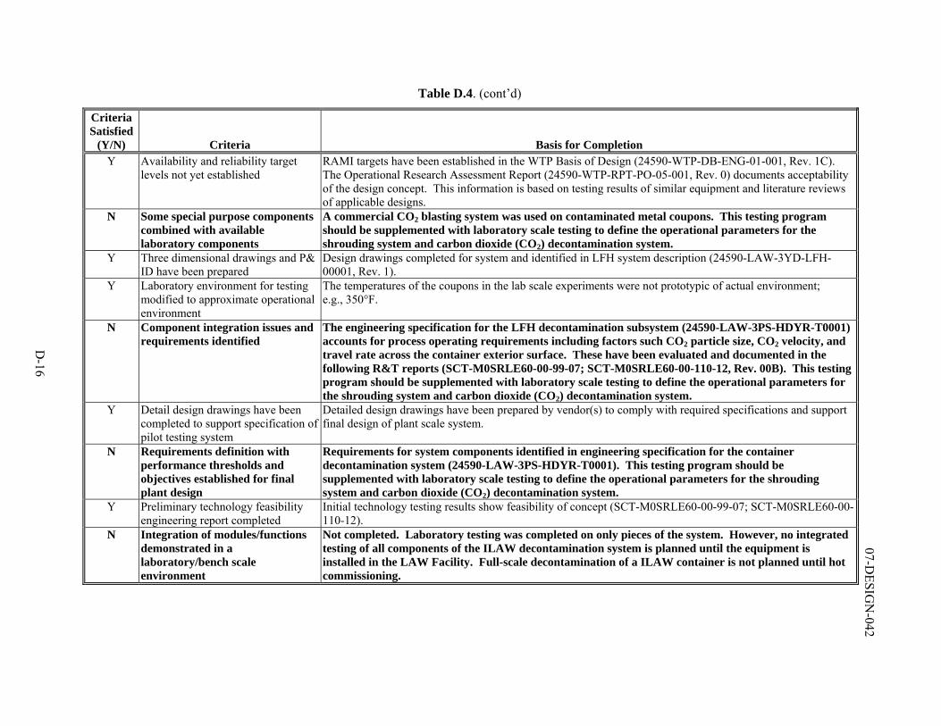
D-16
07-DESIG
N-042
Table D.4. (cont’d)
Criteria Satisfied
(Y/N) Criteria Basis for Completion Y Availability and reliability target
levels not yet established RAMI targets have been established in the WTP Basis of Design (24590-WTP-DB-ENG-01-001, Rev. 1C). The Operational Research Assessment Report (24590-WTP-RPT-PO-05-001, Rev. 0) documents acceptability of the design concept. This information is based on testing results of similar equipment and literature reviews of applicable designs.
N Some special purpose components combined with available laboratory components
A commercial CO2 blasting system was used on contaminated metal coupons. This testing program should be supplemented with laboratory scale testing to define the operational parameters for the shrouding system and carbon dioxide (CO2) decontamination system.
Y Three dimensional drawings and P& ID have been prepared
Design drawings completed for system and identified in LFH system description (24590-LAW-3YD-LFH-00001, Rev. 1).
Y Laboratory environment for testing modified to approximate operational environment
The temperatures of the coupons in the lab scale experiments were not prototypic of actual environment; e.g., 350°F.
N Component integration issues and requirements identified
The engineering specification for the LFH decontamination subsystem (24590-LAW-3PS-HDYR-T0001) accounts for process operating requirements including factors such CO2 particle size, CO2 velocity, and travel rate across the container exterior surface. These have been evaluated and documented in the following R&T reports (SCT-M0SRLE60-00-99-07; SCT-M0SRLE60-00-110-12, Rev. 00B). This testing program should be supplemented with laboratory scale testing to define the operational parameters for the shrouding system and carbon dioxide (CO2) decontamination system.
Y Detail design drawings have been completed to support specification of pilot testing system
Detailed design drawings have been prepared by vendor(s) to comply with required specifications and support final design of plant scale system.
N Requirements definition with performance thresholds and objectives established for final plant design
Requirements for system components identified in engineering specification for the container decontamination system (24590-LAW-3PS-HDYR-T0001). This testing program should be supplemented with laboratory scale testing to define the operational parameters for the shrouding system and carbon dioxide (CO2) decontamination system.
Y Preliminary technology feasibility engineering report completed
Initial technology testing results show feasibility of concept (SCT-M0SRLE60-00-99-07; SCT-M0SRLE60-00-110-12).
N Integration of modules/functions demonstrated in a laboratory/bench scale environment
Not completed. Laboratory testing was completed on only pieces of the system. However, no integrated testing of all components of the ILAW decontamination system is planned until the equipment is installed in the LAW Facility. Full-scale decontamination of a ILAW container is not planned until hot commissioning.
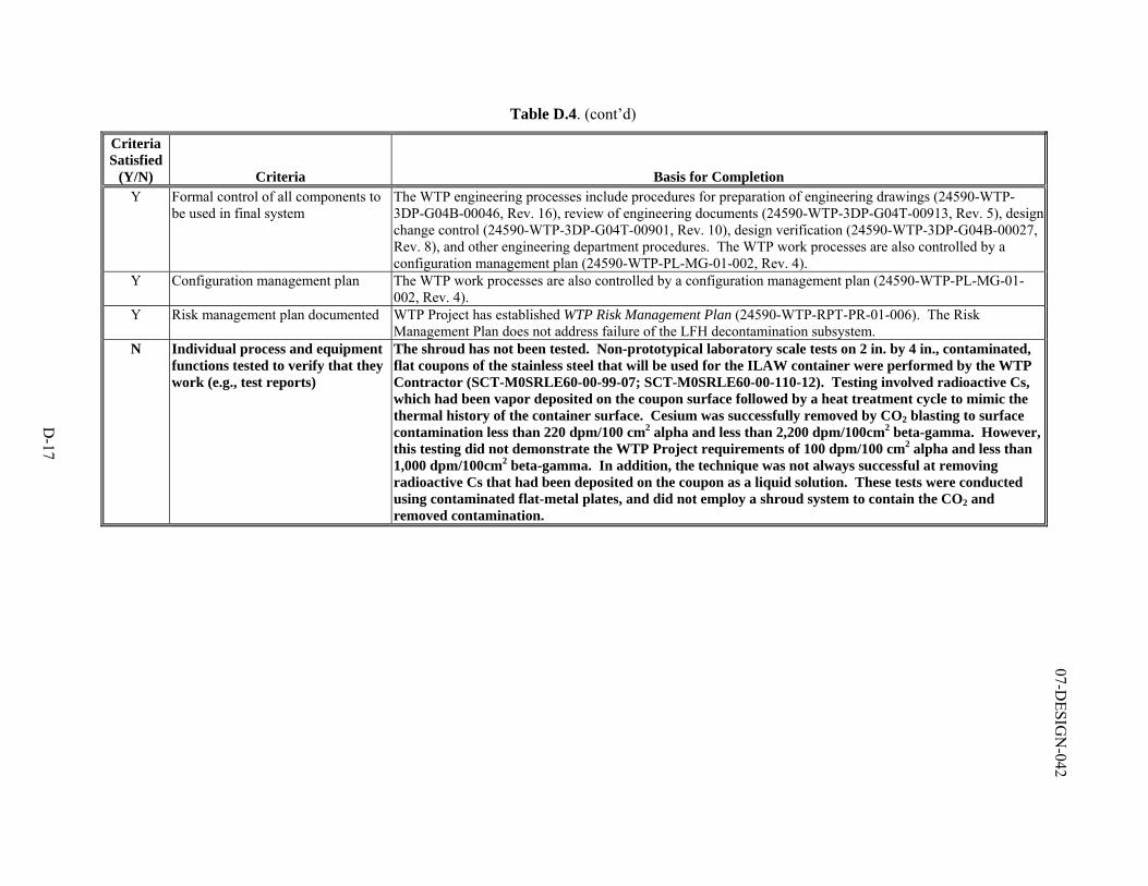
D-17
07-DESIG
N-042
Table D.4. (cont’d)
Criteria Satisfied
(Y/N) Criteria Basis for Completion Y Formal control of all components to
be used in final system The WTP engineering processes include procedures for preparation of engineering drawings (24590-WTP-3DP-G04B-00046, Rev. 16), review of engineering documents (24590-WTP-3DP-G04T-00913, Rev. 5), design change control (24590-WTP-3DP-G04T-00901, Rev. 10), design verification (24590-WTP-3DP-G04B-00027, Rev. 8), and other engineering department procedures. The WTP work processes are also controlled by a configuration management plan (24590-WTP-PL-MG-01-002, Rev. 4).
Y Configuration management plan The WTP work processes are also controlled by a configuration management plan (24590-WTP-PL-MG-01-002, Rev. 4).
Y Risk management plan documented WTP Project has established WTP Risk Management Plan (24590-WTP-RPT-PR-01-006). The Risk Management Plan does not address failure of the LFH decontamination subsystem.
N Individual process and equipment functions tested to verify that they work (e.g., test reports)
The shroud has not been tested. Non-prototypical laboratory scale tests on 2 in. by 4 in., contaminated, flat coupons of the stainless steel that will be used for the ILAW container were performed by the WTP Contractor (SCT-M0SRLE60-00-99-07; SCT-M0SRLE60-00-110-12). Testing involved radioactive Cs, which had been vapor deposited on the coupon surface followed by a heat treatment cycle to mimic the thermal history of the container surface. Cesium was successfully removed by CO2 blasting to surface contamination less than 220 dpm/100 cm2 alpha and less than 2,200 dpm/100cm2 beta-gamma. However, this testing did not demonstrate the WTP Project requirements of 100 dpm/100 cm2 alpha and less than 1,000 dpm/100cm2 beta-gamma. In addition, the technique was not always successful at removing radioactive Cs that had been deposited on the coupon as a liquid solution. These tests were conducted using contaminated flat-metal plates, and did not employ a shroud system to contain the CO2 and removed contamination.
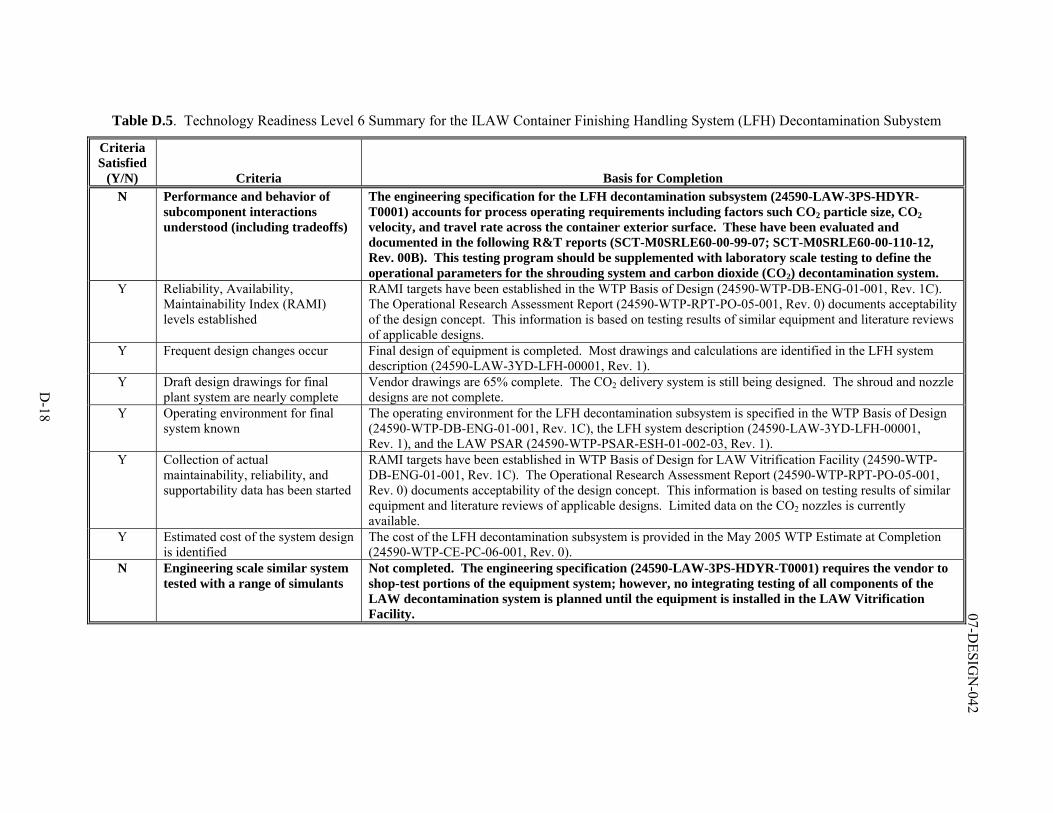
D-18
07-DESIG
N-042
Table D.5. Technology Readiness Level 6 Summary for the ILAW Container Finishing Handling System (LFH) Decontamination Subystem
Criteria Satisfied
(Y/N) Criteria Basis for Completion N Performance and behavior of
subcomponent interactions understood (including tradeoffs)
The engineering specification for the LFH decontamination subsystem (24590-LAW-3PS-HDYR-T0001) accounts for process operating requirements including factors such CO2 particle size, CO2 velocity, and travel rate across the container exterior surface. These have been evaluated and documented in the following R&T reports (SCT-M0SRLE60-00-99-07; SCT-M0SRLE60-00-110-12, Rev. 00B). This testing program should be supplemented with laboratory scale testing to define the operational parameters for the shrouding system and carbon dioxide (CO2) decontamination system.
Y Reliability, Availability, Maintainability Index (RAMI) levels established
RAMI targets have been established in the WTP Basis of Design (24590-WTP-DB-ENG-01-001, Rev. 1C). The Operational Research Assessment Report (24590-WTP-RPT-PO-05-001, Rev. 0) documents acceptability of the design concept. This information is based on testing results of similar equipment and literature reviews of applicable designs.
Y Frequent design changes occur Final design of equipment is completed. Most drawings and calculations are identified in the LFH system description (24590-LAW-3YD-LFH-00001, Rev. 1).
Y Draft design drawings for final plant system are nearly complete
Vendor drawings are 65% complete. The CO2 delivery system is still being designed. The shroud and nozzle designs are not complete.
Y Operating environment for final system known
The operating environment for the LFH decontamination subsystem is specified in the WTP Basis of Design (24590-WTP-DB-ENG-01-001, Rev. 1C), the LFH system description (24590-LAW-3YD-LFH-00001, Rev. 1), and the LAW PSAR (24590-WTP-PSAR-ESH-01-002-03, Rev. 1).
Y Collection of actual maintainability, reliability, and supportability data has been started
RAMI targets have been established in WTP Basis of Design for LAW Vitrification Facility (24590-WTP-DB-ENG-01-001, Rev. 1C). The Operational Research Assessment Report (24590-WTP-RPT-PO-05-001, Rev. 0) documents acceptability of the design concept. This information is based on testing results of similar equipment and literature reviews of applicable designs. Limited data on the CO2 nozzles is currently available.
Y Estimated cost of the system design is identified
The cost of the LFH decontamination subsystem is provided in the May 2005 WTP Estimate at Completion (24590-WTP-CE-PC-06-001, Rev. 0).
N Engineering scale similar system tested with a range of simulants
Not completed. The engineering specification (24590-LAW-3PS-HDYR-T0001) requires the vendor to shop-test portions of the equipment system; however, no integrating testing of all components of the LAW decontamination system is planned until the equipment is installed in the LAW Vitrification Facility.
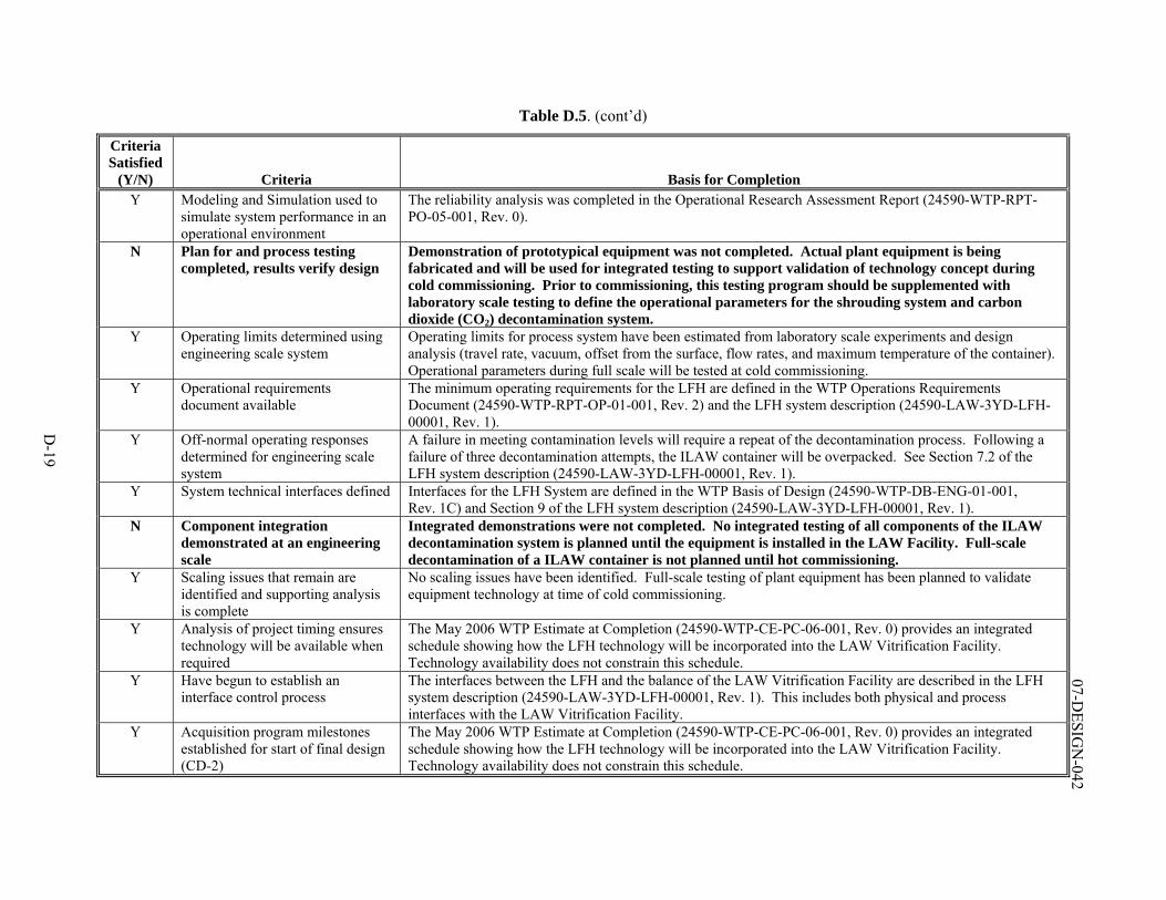
D-19
07-DESIG
N-042
Table D.5. (cont’d)
Criteria Satisfied
(Y/N) Criteria Basis for Completion Y Modeling and Simulation used to
simulate system performance in an operational environment
The reliability analysis was completed in the Operational Research Assessment Report (24590-WTP-RPT-PO-05-001, Rev. 0).
N Plan for and process testing completed, results verify design
Demonstration of prototypical equipment was not completed. Actual plant equipment is being fabricated and will be used for integrated testing to support validation of technology concept during cold commissioning. Prior to commissioning, this testing program should be supplemented with laboratory scale testing to define the operational parameters for the shrouding system and carbon dioxide (CO2) decontamination system.
Y Operating limits determined using engineering scale system
Operating limits for process system have been estimated from laboratory scale experiments and design analysis (travel rate, vacuum, offset from the surface, flow rates, and maximum temperature of the container). Operational parameters during full scale will be tested at cold commissioning.
Y Operational requirements document available
The minimum operating requirements for the LFH are defined in the WTP Operations Requirements Document (24590-WTP-RPT-OP-01-001, Rev. 2) and the LFH system description (24590-LAW-3YD-LFH-00001, Rev. 1).
Y Off-normal operating responses determined for engineering scale system
A failure in meeting contamination levels will require a repeat of the decontamination process. Following a failure of three decontamination attempts, the ILAW container will be overpacked. See Section 7.2 of the LFH system description (24590-LAW-3YD-LFH-00001, Rev. 1).
Y System technical interfaces defined Interfaces for the LFH System are defined in the WTP Basis of Design (24590-WTP-DB-ENG-01-001, Rev. 1C) and Section 9 of the LFH system description (24590-LAW-3YD-LFH-00001, Rev. 1).
N Component integration demonstrated at an engineering scale
Integrated demonstrations were not completed. No integrated testing of all components of the ILAW decontamination system is planned until the equipment is installed in the LAW Facility. Full-scale decontamination of a ILAW container is not planned until hot commissioning.
Y Scaling issues that remain are identified and supporting analysis is complete
No scaling issues have been identified. Full-scale testing of plant equipment has been planned to validate equipment technology at time of cold commissioning.
Y Analysis of project timing ensures technology will be available when required
The May 2006 WTP Estimate at Completion (24590-WTP-CE-PC-06-001, Rev. 0) provides an integrated schedule showing how the LFH technology will be incorporated into the LAW Vitrification Facility. Technology availability does not constrain this schedule.
Y Have begun to establish an interface control process
The interfaces between the LFH and the balance of the LAW Vitrification Facility are described in the LFH system description (24590-LAW-3YD-LFH-00001, Rev. 1). This includes both physical and process interfaces with the LAW Vitrification Facility.
Y Acquisition program milestones established for start of final design (CD-2)
The May 2006 WTP Estimate at Completion (24590-WTP-CE-PC-06-001, Rev. 0) provides an integrated schedule showing how the LFH technology will be incorporated into the LAW Vitrification Facility. Technology availability does not constrain this schedule.
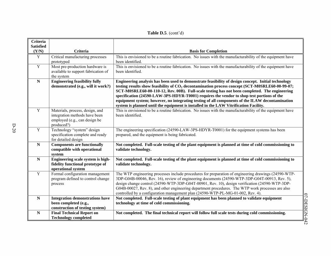
D-20
07-DESIG
N-042
Table D.5. (cont’d)
Criteria Satisfied
(Y/N) Criteria Basis for Completion Y Critical manufacturing processes
prototyped This is envisioned to be a routine fabrication. No issues with the manufacturability of the equipment have been identified.
Y Most pre-production hardware is available to support fabrication of the system
This is envisioned to be a routine fabrication. No issues with the manufacturability of the equipment have been identified.
N Engineering feasibility fully demonstrated (e.g., will it work?)
Engineering analysis has been used to demonstrate feasibility of design concept. Initial technology testing results show feasibility of CO2 decontamination process concept (SCT-M0SRLE60-00-99-07; SCT-M0SRLE60-00-110-12, Rev. 00B). Full-scale testing has not been completed. The engineering specification (24590-LAW-3PS-HDYR-T0001) requires the vendor to shop test portions of the equipment system; however, no integrating testing of all components of the ILAW decontamination system is planned until the equipment is installed in the LAW Vitrification Facility.
Y Materials, process, design, and integration methods have been employed (e.g., can design be produced?)
This is envisioned to be a routine fabrication. No issues with the manufacturability of the equipment have been identified.
Y Technology “system” design specification complete and ready for detailed design
The engineering specification (24590-LAW-3PS-HDYR-T0001) for the equipment systems has been prepared, and the equipment is being fabricated.
N Components are functionally compatible with operational system
Not completed. Full-scale testing of the plant equipment is planned at time of cold commissioning to validate technology.
N Engineering scale system is high-fidelity functional prototype of operational system
Not completed. Full-scale testing of the plant equipment is planned at time of cold commissioning to validate technology.
Y Formal configuration management program defined to control change process
The WTP engineering processes include procedures for preparation of engineering drawings (24590-WTP-3DP-G04B-00046, Rev. 16), review of engineering documents (24590-WTP-3DP-G04T-00913, Rev. 5), design change control (24590-WTP-3DP-G04T-00901, Rev. 10), design verification (24590-WTP-3DP-G04B-00027, Rev. 8), and other engineering department procedures. The WTP work processes are also controlled by a configuration management plan (24590-WTP-PL-MG-01-002, Rev. 4).
N Integration demonstrations have been completed (e.g., construction of testing system)
Not completed. Full-scale testing of plant equipment has been planned to validate equipment technology at time of cold commissioning.
N Final Technical Report on Technology completed
Not completed. The final technical report will follow full scale tests during cold commissioning.
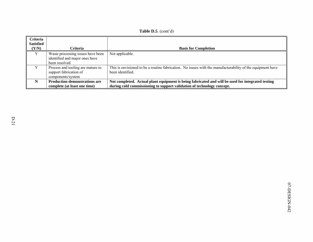
D-21
07-DESIG
N-042
Table D.5. (cont’d)
Criteria Satisfied
(Y/N) Criteria Basis for Completion Y Waste processing issues have been
identified and major ones have been resolved
Not applicable.
Y Process and tooling are mature to support fabrication of components/system
This is envisioned to be a routine fabrication. No issues with the manufacturability of the equipment have been identified.
N Production demonstrations are complete (at least one time)
Not completed. Actual plant equipment is being fabricated and will be used for integrated testing during cold commissioning to support validation of technology concept.
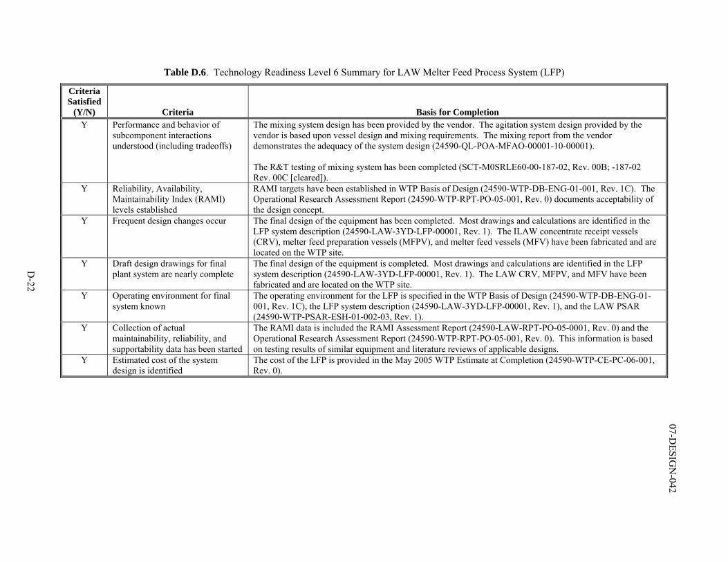
D-22
07-DESIG
N-042
Table D.6. Technology Readiness Level 6 Summary for LAW Melter Feed Process System (LFP)
Criteria Satisfied
(Y/N) Criteria Basis for Completion Y Performance and behavior of
subcomponent interactions understood (including tradeoffs)
The mixing system design has been provided by the vendor. The agitation system design provided by the vendor is based upon vessel design and mixing requirements. The mixing report from the vendor demonstrates the adequacy of the system design (24590-QL-POA-MFAO-00001-10-00001). The R&T testing of mixing system has been completed (SCT-M0SRLE60-00-187-02, Rev. 00B; -187-02 Rev. 00C [cleared]).
Y Reliability, Availability, Maintainability Index (RAMI) levels established
RAMI targets have been established in WTP Basis of Design (24590-WTP-DB-ENG-01-001, Rev. 1C). The Operational Research Assessment Report (24590-WTP-RPT-PO-05-001, Rev. 0) documents acceptability of the design concept.
Y Frequent design changes occur The final design of the equipment has been completed. Most drawings and calculations are identified in the LFP system description (24590-LAW-3YD-LFP-00001, Rev. 1). The ILAW concentrate receipt vessels (CRV), melter feed preparation vessels (MFPV), and melter feed vessels (MFV) have been fabricated and are located on the WTP site.
Y Draft design drawings for final plant system are nearly complete
The final design of the equipment is completed. Most drawings and calculations are identified in the LFP system description (24590-LAW-3YD-LFP-00001, Rev. 1). The LAW CRV, MFPV, and MFV have been fabricated and are located on the WTP site.
Y Operating environment for final system known
The operating environment for the LFP is specified in the WTP Basis of Design (24590-WTP-DB-ENG-01-001, Rev. 1C), the LFP system description (24590-LAW-3YD-LFP-00001, Rev. 1), and the LAW PSAR (24590-WTP-PSAR-ESH-01-002-03, Rev. 1).
Y Collection of actual maintainability, reliability, and supportability data has been started
The RAMI data is included the RAMI Assessment Report (24590-LAW-RPT-PO-05-0001, Rev. 0) and the Operational Research Assessment Report (24590-WTP-RPT-PO-05-001, Rev. 0). This information is based on testing results of similar equipment and literature reviews of applicable designs.
Y Estimated cost of the system design is identified
The cost of the LFP is provided in the May 2005 WTP Estimate at Completion (24590-WTP-CE-PC-06-001, Rev. 0).
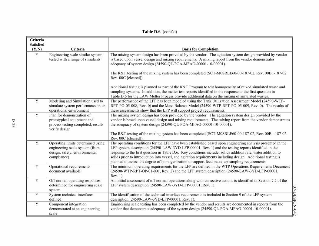
D-23
07-DESIG
N-042
Table D.6. (cont’d)
Criteria Satisfied
(Y/N) Criteria Basis for Completion Y Engineering scale similar system
tested with a range of simulants The mixing system design has been provided by the vendor. The agitation system design provided by vendor is based upon vessel design and mixing requirements. A mixing report from the vendor demonstrates adequacy of system design (24590-QL-POA-MFAO-00001-10-00001). The R&T testing of the mixing system has been completed (SCT-M0SRLE60-00-187-02, Rev. 00B; -187-02 Rev. 00C [cleared]). Additional testing is planned as part of the R&T Program to test homogeneity of mixed simulated waste and sampling systems. In addition, the melter test reports identified in the response to the first question in Table D.6 for the LAW Melter Process provide additional data on the mixing of simulated wastes.
Y Modeling and Simulation used to simulate system performance in an operational environment
The performance of the LFP has been modeled using the Tank Utilization Assessment Model (24590-WTP-RPT-PO-05-008, Rev. 0) and the Mass Balance Model (24590-WTP-RPT-PO-05-009, Rev. 0). The results of these assessments show that the LFP will support project requirements.
Y Plan for demonstration of prototypical equipment and process testing completed, results verify design
The mixing system design has been provided by the vendor. The agitation system design provided by the vendor is based upon vessel design and mixing requirements. The mixing report from the vendor demonstrates the adequacy of system design (24590-QL-POA-MFAO-00001-10-00001). The R&T testing of the mixing system has been completed (SCT-M0SRLE60-00-187-02, Rev. 00B; -187-02 Rev. 00C [cleared]).
Y Operating limits determined using engineering scale system (from design, safety, environmental compliance)
The operating conditions for the LFP have been established based upon engineering analysis presented in the LFP system description (24590-LAW-3YD-LFP-00001, Rev. 1) and the testing reports identified in the response to the first question in Table D.6. Key conditions include; solids addition rate, water addition to solids prior to introduction into vessel, and agitation requirements including design. Additional testing is planned to assess the degree of homogenization to support feed make-up sampling requirements.
Y Operational requirements document available
The minimum operating requirements for the LFP are defined in the WTP Operations Requirements Document (24590-WTP-RPT-OP-01-001, Rev. 2) and the LFP system description (24590-LAW-3YD-LFP-00001, Rev. 1).
Y Off-normal operating responses determined for engineering scale system
An initial assessment of off-normal operations along with corrective actions is identified in Section 7.2 of the LFP system description (24590-LAW-3YD-LFP-00001, Rev. 1).
Y System technical interfaces defined
The identification of the technical interface requirements is included in Section 9 of the LFP system description (24590-LAW-3YD-LFP-00001, Rev. 1).
Y Component integration demonstrated at an engineering scale
Engineering scale testing has been completed by the vendor and results are documented in reports from the vendor that demonstrate adequacy of the system design (24590-QL-POA-MFAO-00001-10-00001).
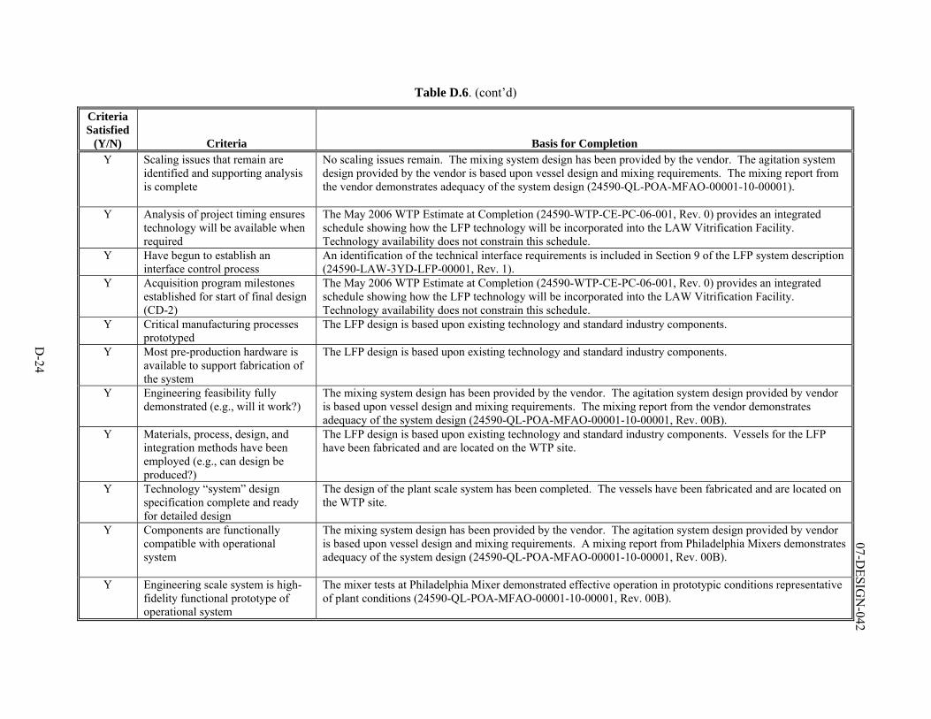
D-24
07-DESIG
N-042
Table D.6. (cont’d)
Criteria Satisfied
(Y/N) Criteria Basis for Completion Y Scaling issues that remain are
identified and supporting analysis is complete
No scaling issues remain. The mixing system design has been provided by the vendor. The agitation system design provided by the vendor is based upon vessel design and mixing requirements. The mixing report from the vendor demonstrates adequacy of the system design (24590-QL-POA-MFAO-00001-10-00001).
Y Analysis of project timing ensures technology will be available when required
The May 2006 WTP Estimate at Completion (24590-WTP-CE-PC-06-001, Rev. 0) provides an integrated schedule showing how the LFP technology will be incorporated into the LAW Vitrification Facility. Technology availability does not constrain this schedule.
Y Have begun to establish an interface control process
An identification of the technical interface requirements is included in Section 9 of the LFP system description (24590-LAW-3YD-LFP-00001, Rev. 1).
Y Acquisition program milestones established for start of final design (CD-2)
The May 2006 WTP Estimate at Completion (24590-WTP-CE-PC-06-001, Rev. 0) provides an integrated schedule showing how the LFP technology will be incorporated into the LAW Vitrification Facility. Technology availability does not constrain this schedule.
Y Critical manufacturing processes prototyped
The LFP design is based upon existing technology and standard industry components.
Y Most pre-production hardware is available to support fabrication of the system
The LFP design is based upon existing technology and standard industry components.
Y Engineering feasibility fully demonstrated (e.g., will it work?)
The mixing system design has been provided by the vendor. The agitation system design provided by vendor is based upon vessel design and mixing requirements. The mixing report from the vendor demonstrates adequacy of the system design (24590-QL-POA-MFAO-00001-10-00001, Rev. 00B).
Y Materials, process, design, and integration methods have been employed (e.g., can design be produced?)
The LFP design is based upon existing technology and standard industry components. Vessels for the LFP have been fabricated and are located on the WTP site.
Y Technology “system” design specification complete and ready for detailed design
The design of the plant scale system has been completed. The vessels have been fabricated and are located on the WTP site.
Y Components are functionally compatible with operational system
The mixing system design has been provided by the vendor. The agitation system design provided by vendor is based upon vessel design and mixing requirements. A mixing report from Philadelphia Mixers demonstrates adequacy of the system design (24590-QL-POA-MFAO-00001-10-00001, Rev. 00B).
Y Engineering scale system is high-fidelity functional prototype of operational system
The mixer tests at Philadelphia Mixer demonstrated effective operation in prototypic conditions representative of plant conditions (24590-QL-POA-MFAO-00001-10-00001, Rev. 00B).
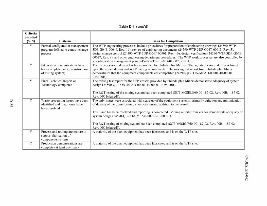
D-25
07-DESIG
N-042
Table D.6. (cont’d)
Criteria Satisfied
(Y/N) Criteria Basis for Completion Y Formal configuration management
program defined to control change process
The WTP engineering processes include procedures for preparation of engineering drawings (24590-WTP-3DP-G04B-00046, Rev. 16), review of engineering documents (24590-WTP-3DP-G04T-00913, Rev. 5), design change control (24590-WTP-3DP-G04T-00901, Rev. 10), design verification (24590-WTP-3DP-G04B-00027, Rev. 8), and other engineering department procedures. The WTP work processes are also controlled by a configuration management plan (24590-WTP-PL-MG-01-002, Rev. 4).
Y Integration demonstrations have been completed (e.g., construction of testing system)
The mixing system design has been provided by Philadelphia Mixers. The agitation system design is based upon the vessel design and WTP mixing requirements. The mixing test report from Philadelphia Mixer demonstrates that the equipment components are compatible (24590-QL-POA-MFAO-00001-10-00001, Rev. 00B).
Y Final Technical Report on Technology completed
The mixing test report for the LFP vessels provided by Philadelphia Mixers demonstrate adequacy of system design (24590-QL-POA-MFAO-00001-10-00001, Rev. 00B). The R&T testing of the mixing system has been completed (SCT-M0SRLE60-00-187-02, Rev. 00B; -187-02 Rev. 00C [cleared]).
Y Waste processing issues have been identified and major ones have been resolved
The only issues were associated with scale-up of the equipment systems, primarily agitation and minimization of dusting of the glass-forming chemicals during addition to the vessel. This issue has been resolved and reporting is completed. Mixing reports from vendor demonstrate adequacy of system design (24590-QL-POA-MFAO-00001-10-00001). The R&T testing of mixing system has been completed (SCT-M0SRLE60-00-187-02, Rev. 00B; -187-02 Rev. 00C [cleared]).
Y Process and tooling are mature to support fabrication of components/system
A majority of the plant equipment has been fabricated and is on the WTP site.
Y Production demonstrations are complete (at least one time)
A majority of the plant equipment has been fabricated and is on the WTP site.
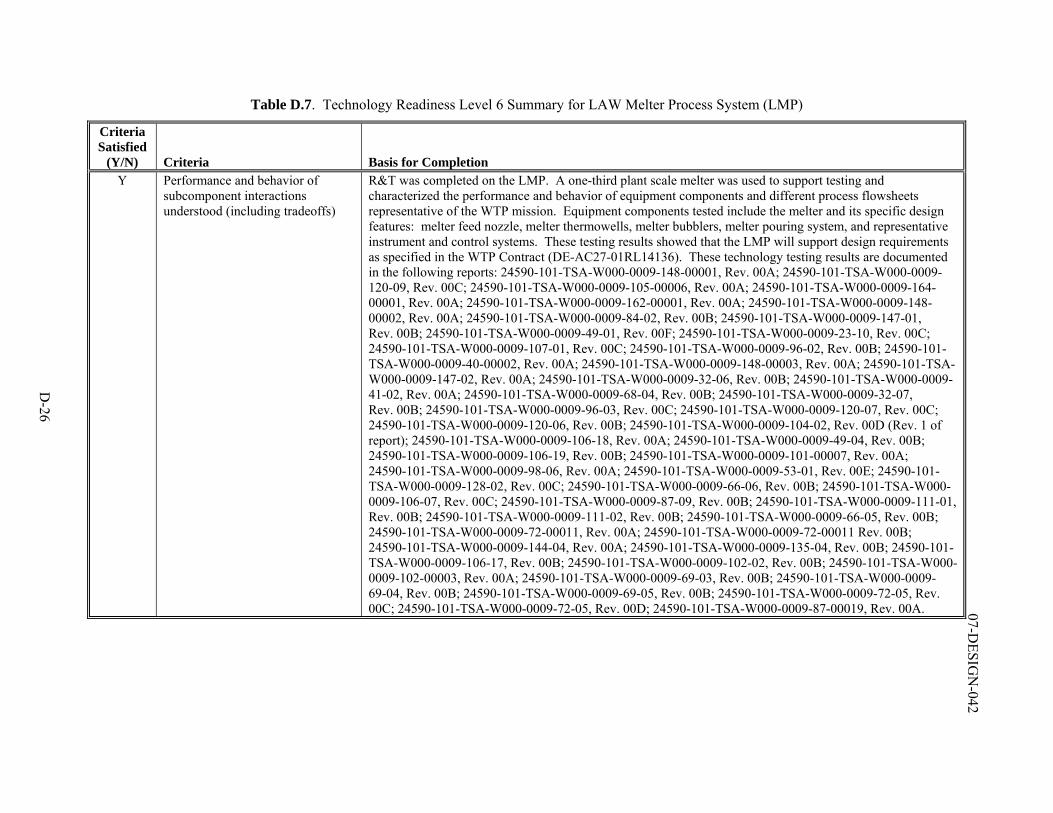
D-26
07-DESIG
N-042
Table D.7. Technology Readiness Level 6 Summary for LAW Melter Process System (LMP)
Criteria Satisfied
(Y/N) Criteria Basis for Completion Y Performance and behavior of
subcomponent interactions understood (including tradeoffs)
R&T was completed on the LMP. A one-third plant scale melter was used to support testing and characterized the performance and behavior of equipment components and different process flowsheets representative of the WTP mission. Equipment components tested include the melter and its specific design features: melter feed nozzle, melter thermowells, melter bubblers, melter pouring system, and representative instrument and control systems. These testing results showed that the LMP will support design requirements as specified in the WTP Contract (DE-AC27-01RL14136). These technology testing results are documented in the following reports: 24590-101-TSA-W000-0009-148-00001, Rev. 00A; 24590-101-TSA-W000-0009-120-09, Rev. 00C; 24590-101-TSA-W000-0009-105-00006, Rev. 00A; 24590-101-TSA-W000-0009-164-00001, Rev. 00A; 24590-101-TSA-W000-0009-162-00001, Rev. 00A; 24590-101-TSA-W000-0009-148-00002, Rev. 00A; 24590-101-TSA-W000-0009-84-02, Rev. 00B; 24590-101-TSA-W000-0009-147-01, Rev. 00B; 24590-101-TSA-W000-0009-49-01, Rev. 00F; 24590-101-TSA-W000-0009-23-10, Rev. 00C; 24590-101-TSA-W000-0009-107-01, Rev. 00C; 24590-101-TSA-W000-0009-96-02, Rev. 00B; 24590-101-TSA-W000-0009-40-00002, Rev. 00A; 24590-101-TSA-W000-0009-148-00003, Rev. 00A; 24590-101-TSA-W000-0009-147-02, Rev. 00A; 24590-101-TSA-W000-0009-32-06, Rev. 00B; 24590-101-TSA-W000-0009-41-02, Rev. 00A; 24590-101-TSA-W000-0009-68-04, Rev. 00B; 24590-101-TSA-W000-0009-32-07, Rev. 00B; 24590-101-TSA-W000-0009-96-03, Rev. 00C; 24590-101-TSA-W000-0009-120-07, Rev. 00C; 24590-101-TSA-W000-0009-120-06, Rev. 00B; 24590-101-TSA-W000-0009-104-02, Rev. 00D (Rev. 1 of report); 24590-101-TSA-W000-0009-106-18, Rev. 00A; 24590-101-TSA-W000-0009-49-04, Rev. 00B; 24590-101-TSA-W000-0009-106-19, Rev. 00B; 24590-101-TSA-W000-0009-101-00007, Rev. 00A; 24590-101-TSA-W000-0009-98-06, Rev. 00A; 24590-101-TSA-W000-0009-53-01, Rev. 00E; 24590-101-TSA-W000-0009-128-02, Rev. 00C; 24590-101-TSA-W000-0009-66-06, Rev. 00B; 24590-101-TSA-W000-0009-106-07, Rev. 00C; 24590-101-TSA-W000-0009-87-09, Rev. 00B; 24590-101-TSA-W000-0009-111-01, Rev. 00B; 24590-101-TSA-W000-0009-111-02, Rev. 00B; 24590-101-TSA-W000-0009-66-05, Rev. 00B; 24590-101-TSA-W000-0009-72-00011, Rev. 00A; 24590-101-TSA-W000-0009-72-00011 Rev. 00B; 24590-101-TSA-W000-0009-144-04, Rev. 00A; 24590-101-TSA-W000-0009-135-04, Rev. 00B; 24590-101-TSA-W000-0009-106-17, Rev. 00B; 24590-101-TSA-W000-0009-102-02, Rev. 00B; 24590-101-TSA-W000-0009-102-00003, Rev. 00A; 24590-101-TSA-W000-0009-69-03, Rev. 00B; 24590-101-TSA-W000-0009-69-04, Rev. 00B; 24590-101-TSA-W000-0009-69-05, Rev. 00B; 24590-101-TSA-W000-0009-72-05, Rev. 00C; 24590-101-TSA-W000-0009-72-05, Rev. 00D; 24590-101-TSA-W000-0009-87-00019, Rev. 00A.
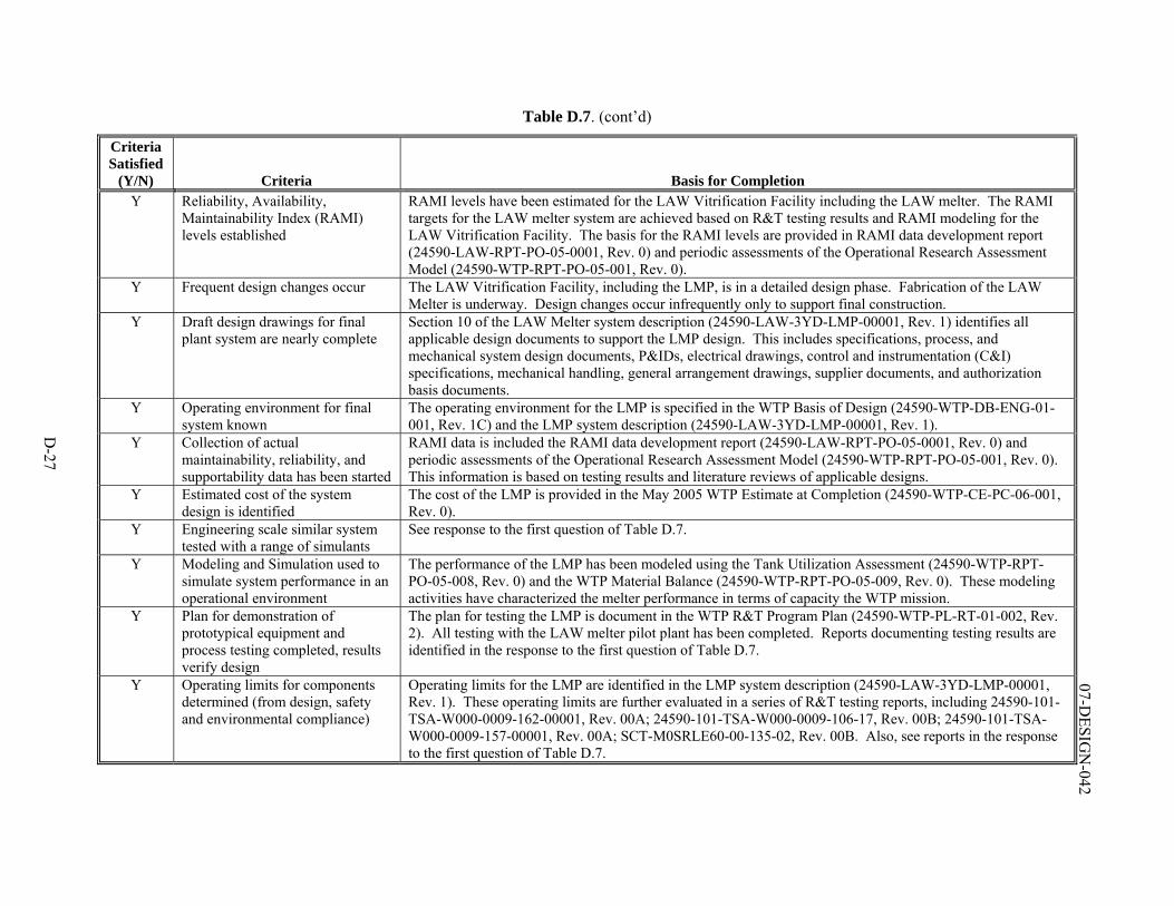
D-27
07-DESIG
N-042
Table D.7. (cont’d)
Criteria Satisfied
(Y/N) Criteria Basis for Completion Y Reliability, Availability,
Maintainability Index (RAMI) levels established
RAMI levels have been estimated for the LAW Vitrification Facility including the LAW melter. The RAMI targets for the LAW melter system are achieved based on R&T testing results and RAMI modeling for the LAW Vitrification Facility. The basis for the RAMI levels are provided in RAMI data development report (24590-LAW-RPT-PO-05-0001, Rev. 0) and periodic assessments of the Operational Research Assessment Model (24590-WTP-RPT-PO-05-001, Rev. 0).
Y Frequent design changes occur The LAW Vitrification Facility, including the LMP, is in a detailed design phase. Fabrication of the LAW Melter is underway. Design changes occur infrequently only to support final construction.
Y Draft design drawings for final plant system are nearly complete
Section 10 of the LAW Melter system description (24590-LAW-3YD-LMP-00001, Rev. 1) identifies all applicable design documents to support the LMP design. This includes specifications, process, and mechanical system design documents, P&IDs, electrical drawings, control and instrumentation (C&I) specifications, mechanical handling, general arrangement drawings, supplier documents, and authorization basis documents.
Y Operating environment for final system known
The operating environment for the LMP is specified in the WTP Basis of Design (24590-WTP-DB-ENG-01-001, Rev. 1C) and the LMP system description (24590-LAW-3YD-LMP-00001, Rev. 1).
Y Collection of actual maintainability, reliability, and supportability data has been started
RAMI data is included the RAMI data development report (24590-LAW-RPT-PO-05-0001, Rev. 0) and periodic assessments of the Operational Research Assessment Model (24590-WTP-RPT-PO-05-001, Rev. 0). This information is based on testing results and literature reviews of applicable designs.
Y Estimated cost of the system design is identified
The cost of the LMP is provided in the May 2005 WTP Estimate at Completion (24590-WTP-CE-PC-06-001, Rev. 0).
Y Engineering scale similar system tested with a range of simulants
See response to the first question of Table D.7.
Y Modeling and Simulation used to simulate system performance in an operational environment
The performance of the LMP has been modeled using the Tank Utilization Assessment (24590-WTP-RPT-PO-05-008, Rev. 0) and the WTP Material Balance (24590-WTP-RPT-PO-05-009, Rev. 0). These modeling activities have characterized the melter performance in terms of capacity the WTP mission.
Y Plan for demonstration of prototypical equipment and process testing completed, results verify design
The plan for testing the LMP is document in the WTP R&T Program Plan (24590-WTP-PL-RT-01-002, Rev. 2). All testing with the LAW melter pilot plant has been completed. Reports documenting testing results are identified in the response to the first question of Table D.7.
Y Operating limits for components determined (from design, safety and environmental compliance)
Operating limits for the LMP are identified in the LMP system description (24590-LAW-3YD-LMP-00001, Rev. 1). These operating limits are further evaluated in a series of R&T testing reports, including 24590-101-TSA-W000-0009-162-00001, Rev. 00A; 24590-101-TSA-W000-0009-106-17, Rev. 00B; 24590-101-TSA-W000-0009-157-00001, Rev. 00A; SCT-M0SRLE60-00-135-02, Rev. 00B. Also, see reports in the response to the first question of Table D.7.
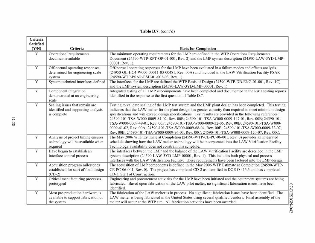
D-28
07-DESIG
N-042
Table D.7. (cont’d)
Criteria Satisfied
(Y/N) Criteria Basis for Completion Y Operational requirements
document available The minimum operating requirements for the LMP are defined in the WTP Operations Requirements Document (24590-WTP-RPT-OP-01-001, Rev. 2) and the LMP system description (24590-LAW-3YD-LMP-00001, Rev. 1).
Y Off-normal operating responses determined for engineering scale system
Off-normal operating responses for the LMP have been evaluated in a failure modes and effects analysis (24950-QL-HC4-W000-00011-03-00481, Rev. 00A) and included in the LAW Vitrification Facility PSAR (24590-WTP-PSAR-ESH-01-002-03, Rev. 1).
Y System technical interfaces defined The interfaces for the LMP are defined the WTP Basis of Design (24590-WTP-DB-ENG-01-001, Rev. 1C) and the LMP system description (24590-LAW-3YD-LMP-00001, Rev. 1)
Y Component integration demonstrated at an engineering scale
Integrated testing of all LMP subcomponents have been completed and documented in the R&T testing reports identified in the response to the first question of Table D.7.
Y Scaling issues that remain are identified and supporting analysis is complete
Testing to validate scaling of the LMP test system and the LMP plant design has been completed. This testing indicates that the LAW melter for the plant design has greater capacity than required to meet minimum design specifications and will exceed design specifications. Test results are provided in the following references: 24590-101-TSA-W000-0009-84-02, Rev. 00B; 24590-101-TSA-W000-0009-147-01, Rev. 00B; 24590-101-TSA-W000-0009-49-01, Rev. 00F; 24590-101-TSA-W000-0009-32-06, Rev. 00B; 24590-101-TSA-W000-0009-41-02, Rev. 00A; 24590-101-TSA-W000-0009-68-04, Rev. 00B; 24590-101-TSA-W000-0009-32-07, Rev. 00B; 24590-101-TSA-W000-0009-96-03, Rev. 00C; 24590-101-TSA-W000-0009-120-07, Rev. 00C.
Y Analysis of project timing ensures technology will be available when required
The May 2006 WTP Estimate at Completion (24590-WTP-CE-PC-06-001, Rev. 0) provides an integrated schedule showing how the LAW melter technology will be incorporated into the LAW Vitrification Facility. Technology availability does not constrain this schedule.
Y Have begun to establish an interface control process
The interfaces between the LMP and the balance of the LAW Vitrification Facility are described in the LMP system description (24590-LAW-3YD-LMP-00001, Rev. 1). This includes both physical and process interfaces with the LAW Vitrification Facility. These requirements have been factored into the LMP design.
Y Acquisition program milestones established for start of final design (CD-2)
The acquisition of LMP components is defined in the May 2006 WTP Estimate at Completion (24590-WTP-CE-PC-06-001, Rev. 0). The project has completed CD-2 as identified in DOE O 413.3 and has completed CD-3, Start of Construction.
Y Critical manufacturing processes prototyped
Engineering and procurement activities for the LMP have been initiated and the equipment systems are being fabricated. Based upon fabrication of the LAW pilot melter, no significant fabrication issues have been identified.
Y Most pre-production hardware is available to support fabrication of the system
The fabrication of the LAW melter is in process. No significant fabrication issues have been identified. The LAW melter is being fabricated in the United States using several qualified vendors. Final assembly of the melter will occur at the WTP site. All fabrication activities have been awarded.
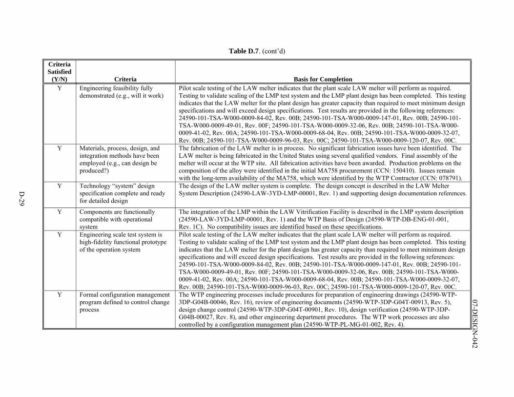
D-29
07-DESIG
N-042
Table D.7. (cont’d)
Criteria Satisfied
(Y/N) Criteria Basis for Completion Y Engineering feasibility fully
demonstrated (e.g., will it work) Pilot scale testing of the LAW melter indicates that the plant scale LAW melter will perform as required. Testing to validate scaling of the LMP test system and the LMP plant design has been completed. This testing indicates that the LAW melter for the plant design has greater capacity than required to meet minimum design specifications and will exceed design specifications. Test results are provided in the following references: 24590-101-TSA-W000-0009-84-02, Rev. 00B; 24590-101-TSA-W000-0009-147-01, Rev. 00B; 24590-101-TSA-W000-0009-49-01, Rev. 00F; 24590-101-TSA-W000-0009-32-06, Rev. 00B; 24590-101-TSA-W000-0009-41-02, Rev. 00A; 24590-101-TSA-W000-0009-68-04, Rev. 00B; 24590-101-TSA-W000-0009-32-07, Rev. 00B; 24590-101-TSA-W000-0009-96-03, Rev. 00C; 24590-101-TSA-W000-0009-120-07, Rev. 00C.
Y Materials, process, design, and integration methods have been employed (e.g., can design be produced?)
The fabrication of the LAW melter is in process. No significant fabrication issues have been identified. The LAW melter is being fabricated in the United States using several qualified vendors. Final assembly of the melter will occur at the WTP site. All fabrication activities have been awarded. Production problems on the composition of the alloy were identified in the initial MA758 procurement (CCN: 150410). Issues remain with the long-term availability of the MA758, which were identified by the WTP Contractor (CCN: 078791).
Y Technology “system” design specification complete and ready for detailed design
The design of the LAW melter system is complete. The design concept is described in the LAW Melter System Description (24590-LAW-3YD-LMP-00001, Rev. 1) and supporting design documentation references.
Y Components are functionally compatible with operational system
The integration of the LMP within the LAW Vitrification Facility is described in the LMP system description (24590-LAW-3YD-LMP-00001, Rev. 1) and the WTP Basis of Design (24590-WTP-DB-ENG-01-001, Rev. 1C). No compatibility issues are identified based on these specifications.
Y Engineering scale test system is high-fidelity functional prototype of the operation system
Pilot scale testing of the LAW melter indicates that the plant scale LAW melter will perform as required. Testing to validate scaling of the LMP test system and the LMP plant design has been completed. This testing indicates that the LAW melter for the plant design has greater capacity than required to meet minimum design specifications and will exceed design specifications. Test results are provided in the following references: 24590-101-TSA-W000-0009-84-02, Rev. 00B; 24590-101-TSA-W000-0009-147-01, Rev. 00B; 24590-101-TSA-W000-0009-49-01, Rev. 00F; 24590-101-TSA-W000-0009-32-06, Rev. 00B; 24590-101-TSA-W000-0009-41-02, Rev. 00A; 24590-101-TSA-W000-0009-68-04, Rev. 00B; 24590-101-TSA-W000-0009-32-07, Rev. 00B; 24590-101-TSA-W000-0009-96-03, Rev. 00C; 24590-101-TSA-W000-0009-120-07, Rev. 00C.
Y Formal configuration management program defined to control change process
The WTP engineering processes include procedures for preparation of engineering drawings (24590-WTP-3DP-G04B-00046, Rev. 16), review of engineering documents (24590-WTP-3DP-G04T-00913, Rev. 5), design change control (24590-WTP-3DP-G04T-00901, Rev. 10), design verification (24590-WTP-3DP-G04B-00027, Rev. 8), and other engineering department procedures. The WTP work processes are also controlled by a configuration management plan (24590-WTP-PL-MG-01-002, Rev. 4).
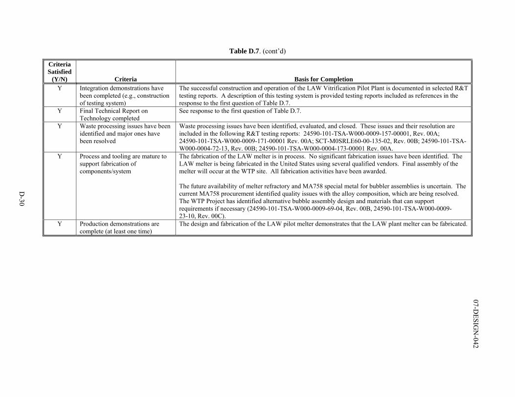
D-30
07-DESIG
N-042
Table D.7. (cont’d)
Criteria Satisfied
(Y/N) Criteria Basis for Completion Y Integration demonstrations have
been completed (e.g., construction of testing system)
The successful construction and operation of the LAW Vitrification Pilot Plant is documented in selected R&T testing reports. A description of this testing system is provided testing reports included as references in the response to the first question of Table D.7.
Y Final Technical Report on Technology completed
See response to the first question of Table D.7.
Y Waste processing issues have been identified and major ones have been resolved
Waste processing issues have been identified, evaluated, and closed. These issues and their resolution are included in the following R&T testing reports: 24590-101-TSA-W000-0009-157-00001, Rev. 00A; 24590-101-TSA-W000-0009-171-00001 Rev. 00A; SCT-M0SRLE60-00-135-02, Rev. 00B; 24590-101-TSA-W000-0004-72-13, Rev. 00B; 24590-101-TSA-W000-0004-173-00001 Rev. 00A.
Y Process and tooling are mature to support fabrication of components/system
The fabrication of the LAW melter is in process. No significant fabrication issues have been identified. The LAW melter is being fabricated in the United States using several qualified vendors. Final assembly of the melter will occur at the WTP site. All fabrication activities have been awarded. The future availability of melter refractory and MA758 special metal for bubbler assemblies is uncertain. The current MA758 procurement identified quality issues with the alloy composition, which are being resolved. The WTP Project has identified alternative bubble assembly design and materials that can support requirements if necessary (24590-101-TSA-W000-0009-69-04, Rev. 00B, 24590-101-TSA-W000-0009-23-10, Rev. 00C).
Y Production demonstrations are complete (at least one time)
The design and fabrication of the LAW pilot melter demonstrates that the LAW plant melter can be fabricated.
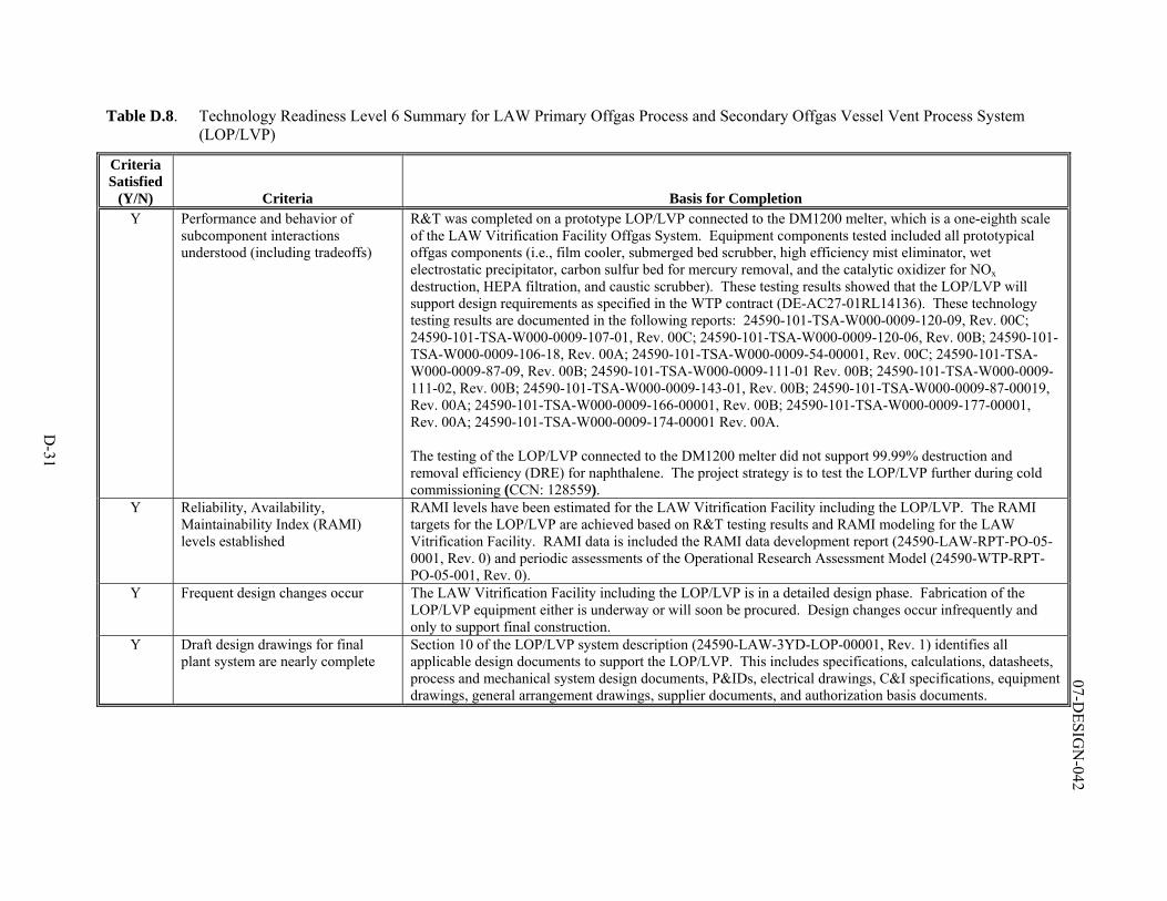
D-31
07-DESIG
N-042
Table D.8. Technology Readiness Level 6 Summary for LAW Primary Offgas Process and Secondary Offgas Vessel Vent Process System (LOP/LVP)
Criteria Satisfied
(Y/N) Criteria Basis for Completion Y Performance and behavior of
subcomponent interactions understood (including tradeoffs)
R&T was completed on a prototype LOP/LVP connected to the DM1200 melter, which is a one-eighth scale of the LAW Vitrification Facility Offgas System. Equipment components tested included all prototypical offgas components (i.e., film cooler, submerged bed scrubber, high efficiency mist eliminator, wet electrostatic precipitator, carbon sulfur bed for mercury removal, and the catalytic oxidizer for NOx destruction, HEPA filtration, and caustic scrubber). These testing results showed that the LOP/LVP will support design requirements as specified in the WTP contract (DE-AC27-01RL14136). These technology testing results are documented in the following reports: 24590-101-TSA-W000-0009-120-09, Rev. 00C; 24590-101-TSA-W000-0009-107-01, Rev. 00C; 24590-101-TSA-W000-0009-120-06, Rev. 00B; 24590-101-TSA-W000-0009-106-18, Rev. 00A; 24590-101-TSA-W000-0009-54-00001, Rev. 00C; 24590-101-TSA-W000-0009-87-09, Rev. 00B; 24590-101-TSA-W000-0009-111-01 Rev. 00B; 24590-101-TSA-W000-0009-111-02, Rev. 00B; 24590-101-TSA-W000-0009-143-01, Rev. 00B; 24590-101-TSA-W000-0009-87-00019, Rev. 00A; 24590-101-TSA-W000-0009-166-00001, Rev. 00B; 24590-101-TSA-W000-0009-177-00001, Rev. 00A; 24590-101-TSA-W000-0009-174-00001 Rev. 00A. The testing of the LOP/LVP connected to the DM1200 melter did not support 99.99% destruction and removal efficiency (DRE) for naphthalene. The project strategy is to test the LOP/LVP further during cold commissioning (CCN: 128559).
Y Reliability, Availability, Maintainability Index (RAMI) levels established
RAMI levels have been estimated for the LAW Vitrification Facility including the LOP/LVP. The RAMI targets for the LOP/LVP are achieved based on R&T testing results and RAMI modeling for the LAW Vitrification Facility. RAMI data is included the RAMI data development report (24590-LAW-RPT-PO-05-0001, Rev. 0) and periodic assessments of the Operational Research Assessment Model (24590-WTP-RPT-PO-05-001, Rev. 0).
Y Frequent design changes occur The LAW Vitrification Facility including the LOP/LVP is in a detailed design phase. Fabrication of the LOP/LVP equipment either is underway or will soon be procured. Design changes occur infrequently and only to support final construction.
Y Draft design drawings for final plant system are nearly complete
Section 10 of the LOP/LVP system description (24590-LAW-3YD-LOP-00001, Rev. 1) identifies all applicable design documents to support the LOP/LVP. This includes specifications, calculations, datasheets, process and mechanical system design documents, P&IDs, electrical drawings, C&I specifications, equipment drawings, general arrangement drawings, supplier documents, and authorization basis documents.
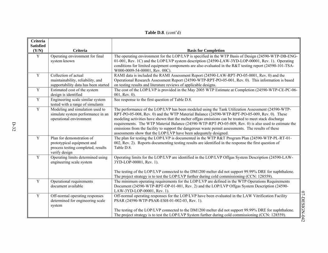
D-32
07-DESIG
N-042
Table D.8. (cont’d)
Criteria Satisfied
(Y/N) Criteria Basis for Completion Y Operating environment for final
system known The operating environment for the LOP/LVP is specified in the WTP Basis of Design (24590-WTP-DB-ENG-01-001, Rev. 1C) and the LOP/LVP system description (24590-LAW-3YD-LOP-00001, Rev. 1). Operating conditions for limited equipment components are also evaluated in the R&T testing report (24590-101-TSA-W000-0009-54-00001, Rev. 00C).
Y Collection of actual maintainability, reliability, and supportability data has been started
RAMI data is included the RAMI Assessment Report (24590-LAW-RPT-PO-05-0001, Rev. 0) and the Operational Research Assessment Report (24590-WTP-RPT-PO-05-001, Rev. 0). This information is based on testing results and literature reviews of applicable designs.
Y Estimated cost of the system design is identified
The cost of the LOP/LVP is provided in the May 2005 WTP Estimate at Completion (24590-WTP-CE-PC-06-001, Rev. 0).
Y Engineering scale similar system tested with a range of simulants
See response to the first question of Table D.8.
Y Modeling and simulation used to simulate system performance in an operational environment
The performance of the LOP/LVP has been modeled using the Tank Utilization Assessment (24590-WTP-RPT-PO-05-008, Rev. 0) and the WTP Material Balance (24590-WTP-RPT-PO-05-009, Rev. 0). These modeling activities have shown that the melter offgas emissions can be treated to meet stack discharge requirements. The WTP Material Balance (24590-WTP-RPT-PO-05-009, Rev. 0) is also used to estimate the emissions from the facility to support the dangerous waste permit assessments. The results of these assessments show that the LOP/LVP have been adequately designed.
Y Plan for demonstration of prototypical equipment and process testing completed, results verify design
The plan for testing the LOP/LVP is documented in the WTP R&T Program Plan (24590-WTP-PL-RT-01-002, Rev. 2). Reports documenting testing results are identified in the response the first question of Table D.8.
Y Operating limits determined using engineering scale system
Operating limits for the LOP/LVP are identified in the LOP/LVP Offgas System Description (24590-LAW-3YD-LOP-00001, Rev. 1). The testing of the LOP/LVP connected to the DM1200 melter did not support 99.99% DRE for naphthalene. The project strategy is to test the LOP/LVP further during cold commissioning (CCN: 128559).
Y Operational requirements document available
The minimum operating requirements for the LOP/LVP are defined in the WTP Operations Requirements Document (24590-WTP-RPT-OP-01-001, Rev. 2) and the LOP/LVP Offgas System Description (24590-LAW-3YD-LOP-00001, Rev. 1).
Y Off-normal operating responses determined for engineering scale system
Off-normal operating responses for the LOP/LVP have been evaluated in the LAW Vitrification Facility PSAR (24590-WTP-PSAR-ESH-01-002-03, Rev. 1). The testing of the LOP/LVP connected to the DM1200 melter did not support 99.99% DRE for naphthalene. The project strategy is to test the LOP/LVP System further during cold commissioning (CCN: 128559).
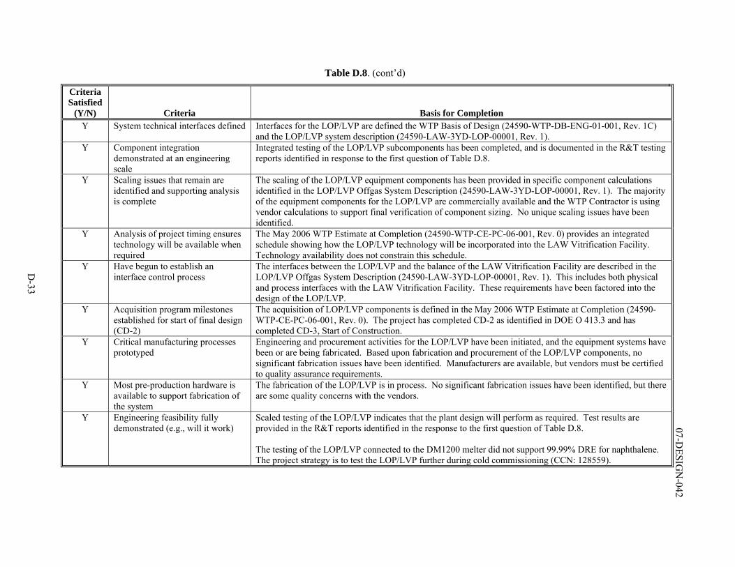
D-33
07-DESIG
N-042
Table D.8. (cont’d)
Criteria Satisfied
(Y/N) Criteria Basis for Completion Y System technical interfaces defined Interfaces for the LOP/LVP are defined the WTP Basis of Design (24590-WTP-DB-ENG-01-001, Rev. 1C)
and the LOP/LVP system description (24590-LAW-3YD-LOP-00001, Rev. 1). Y Component integration
demonstrated at an engineering scale
Integrated testing of the LOP/LVP subcomponents has been completed, and is documented in the R&T testing reports identified in response to the first question of Table D.8.
Y Scaling issues that remain are identified and supporting analysis is complete
The scaling of the LOP/LVP equipment components has been provided in specific component calculations identified in the LOP/LVP Offgas System Description (24590-LAW-3YD-LOP-00001, Rev. 1). The majority of the equipment components for the LOP/LVP are commercially available and the WTP Contractor is using vendor calculations to support final verification of component sizing. No unique scaling issues have been identified.
Y Analysis of project timing ensures technology will be available when required
The May 2006 WTP Estimate at Completion (24590-WTP-CE-PC-06-001, Rev. 0) provides an integrated schedule showing how the LOP/LVP technology will be incorporated into the LAW Vitrification Facility. Technology availability does not constrain this schedule.
Y Have begun to establish an interface control process
The interfaces between the LOP/LVP and the balance of the LAW Vitrification Facility are described in the LOP/LVP Offgas System Description (24590-LAW-3YD-LOP-00001, Rev. 1). This includes both physical and process interfaces with the LAW Vitrification Facility. These requirements have been factored into the design of the LOP/LVP.
Y Acquisition program milestones established for start of final design (CD-2)
The acquisition of LOP/LVP components is defined in the May 2006 WTP Estimate at Completion (24590-WTP-CE-PC-06-001, Rev. 0). The project has completed CD-2 as identified in DOE O 413.3 and has completed CD-3, Start of Construction.
Y Critical manufacturing processes prototyped
Engineering and procurement activities for the LOP/LVP have been initiated, and the equipment systems have been or are being fabricated. Based upon fabrication and procurement of the LOP/LVP components, no significant fabrication issues have been identified. Manufacturers are available, but vendors must be certified to quality assurance requirements.
Y Most pre-production hardware is available to support fabrication of the system
The fabrication of the LOP/LVP is in process. No significant fabrication issues have been identified, but there are some quality concerns with the vendors.
Y Engineering feasibility fully demonstrated (e.g., will it work)
Scaled testing of the LOP/LVP indicates that the plant design will perform as required. Test results are provided in the R&T reports identified in the response to the first question of Table D.8. The testing of the LOP/LVP connected to the DM1200 melter did not support 99.99% DRE for naphthalene. The project strategy is to test the LOP/LVP further during cold commissioning (CCN: 128559).
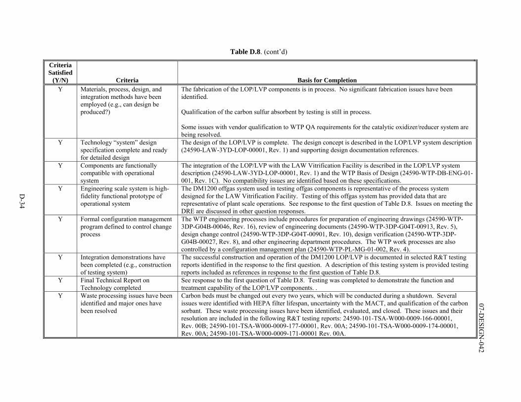
D-34
07-DESIG
N-042
Table D.8. (cont’d)
Criteria Satisfied
(Y/N) Criteria Basis for Completion Y Materials, process, design, and
integration methods have been employed (e.g., can design be produced?)
The fabrication of the LOP/LVP components is in process. No significant fabrication issues have been identified. Qualification of the carbon sulfur absorbent by testing is still in process. Some issues with vendor qualification to WTP QA requirements for the catalytic oxidizer/reducer system are being resolved.
Y Technology “system” design specification complete and ready for detailed design
The design of the LOP/LVP is complete. The design concept is described in the LOP/LVP system description (24590-LAW-3YD-LOP-00001, Rev. 1) and supporting design documentation references.
Y Components are functionally compatible with operational system
The integration of the LOP/LVP with the LAW Vitrification Facility is described in the LOP/LVP system description (24590-LAW-3YD-LOP-00001, Rev. 1) and the WTP Basis of Design (24590-WTP-DB-ENG-01-001, Rev. 1C). No compatibility issues are identified based on these specifications.
Y Engineering scale system is high-fidelity functional prototype of operational system
The DM1200 offgas system used in testing offgas components is representative of the process system designed for the LAW Vitrification Facility. Testing of this offgas system has provided data that are representative of plant scale operations. See response to the first question of Table D.8. Issues on meeting the DRE are discussed in other question responses.
Y Formal configuration management program defined to control change process
The WTP engineering processes include procedures for preparation of engineering drawings (24590-WTP-3DP-G04B-00046, Rev. 16), review of engineering documents (24590-WTP-3DP-G04T-00913, Rev. 5), design change control (24590-WTP-3DP-G04T-00901, Rev. 10), design verification (24590-WTP-3DP-G04B-00027, Rev. 8), and other engineering department procedures. The WTP work processes are also controlled by a configuration management plan (24590-WTP-PL-MG-01-002, Rev. 4).
Y Integration demonstrations have been completed (e.g., construction of testing system)
The successful construction and operation of the DM1200 LOP/LVP is documented in selected R&T testing reports identified in the response to the first question. A description of this testing system is provided testing reports included as references in response to the first question of Table D.8.
Y Final Technical Report on Technology completed
See response to the first question of Table D.8. Testing was completed to demonstrate the function and treatment capability of the LOP/LVP components. .
Y Waste processing issues have been identified and major ones have been resolved
Carbon beds must be changed out every two years, which will be conducted during a shutdown. Several issues were identified with HEPA filter lifespan, uncertainty with the MACT, and qualification of the carbon sorbant. These waste processing issues have been identified, evaluated, and closed. These issues and their resolution are included in the following R&T testing reports: 24590-101-TSA-W000-0009-166-00001, Rev. 00B; 24590-101-TSA-W000-0009-177-00001, Rev. 00A; 24590-101-TSA-W000-0009-174-00001, Rev. 00A; 24590-101-TSA-W000-0009-171-00001 Rev. 00A.
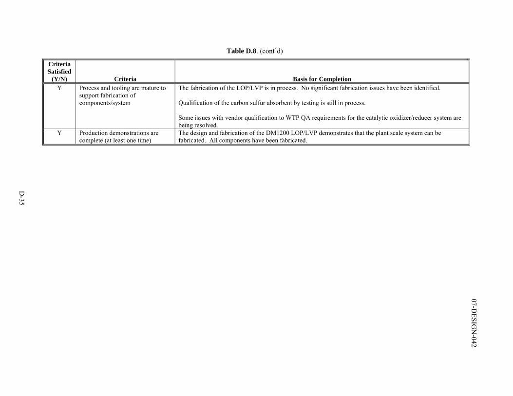
D-35
07-DESIG
N-042
Table D.8. (cont’d)
Criteria Satisfied
(Y/N) Criteria Basis for Completion Y Process and tooling are mature to
support fabrication of components/system
The fabrication of the LOP/LVP is in process. No significant fabrication issues have been identified. Qualification of the carbon sulfur absorbent by testing is still in process. Some issues with vendor qualification to WTP QA requirements for the catalytic oxidizer/reducer system are being resolved.
Y Production demonstrations are complete (at least one time)
The design and fabrication of the DM1200 LOP/LVP demonstrates that the plant scale system can be fabricated. All components have been fabricated.
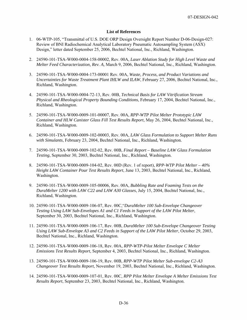
07-DESIGN-042
D-36
List of References
1. 06-WTP-105, “Transmittal of U.S. DOE ORP Design Oversight Report Number D-06-Design-027: Review of BNI Radiochemical Analytical Laboratory Pneumatic Autosampling System (ASX) Design,” letter dated September 25, 2006, Bechtel National, Inc., Richland, Washington.
2. 24590-101-TSA-W000-0004-158-00002, Rev. 00A, Laser Ablation Study for High Level Waste and Melter Feed Characterization, Rev. A, March 9, 2006, Bechtel National, Inc., Richland, Washington.
3. 24590-101-TSA-W000-0004-173-00001 Rev. 00A, Waste, Process, and Product Variations and Uncertainties for Waste Treatment Plant IHLW and ILAW, February 27, 2006, Bechtel National, Inc., Richland, Washington.
4. 24590-101-TSA-W000-0004-72-13, Rev. 00B, Technical Basis for LAW Vitrification Stream Physical and Rheological Property Bounding Conditions, February 17, 2004, Bechtel National, Inc., Richland, Washington.
5. 24590-101-TSA-W000-0009-101-00007, Rev. 00A, RPP-WTP Pilot Melter Prototypic LAW Container and HLW Canister Glass Fill Test Results Report, May 26, 2004, Bechtel National, Inc., Richland, Washington.
6. 24590-101-TSA-W000-0009-102-00003, Rev. 00A, LAW Glass Formulation to Support Melter Runs with Simulants, February 23, 2004, Bechtel National, Inc., Richland, Washington.
7. 24590-101-TSA-W000-0009-102-02, Rev. 00B, Final Report – Baseline LAW Glass Formulation Testing, September 30, 2003, Bechtel National, Inc., Richland, Washington.
8. 24590-101-TSA-W000-0009-104-02, Rev. 00D (Rev. 1 of report), RPP-WTP Pilot Melter – 40% Height LAW Container Pour Test Results Report, June 13, 2003, Bechtel National, Inc., Richland, Washington.
9. 24590-101-TSA-W000-0009-105-00006, Rev. 00A, Bubbling Rate and Foaming Tests on the DuraMelter 1200 with LAW C22 and LAW A30 Glasses, July 15, 2004, Bechtel National, Inc., Richland, Washington.
10. 24590-101-TSA-W000-0009-106-07, Rev. 00C,“DuraMelter 100 Sub-Envelope Changeover Testing Using LAW Sub-Envelopes A1 and C1 Feeds in Support of the LAW Pilot Melter, September 30, 2003, Bechtel National, Inc., Richland, Washington.
11. 24590-101-TSA-W000-0009-106-17, Rev. 00B, DuraMelter 100 Sub-Envelope Changeover Testing Using LAW Sub-Envelope A3 and C2 Feeds in Support of the LAW Pilot Melter, October 29, 2003, Bechtel National, Inc., Richland, Washington.
12. 24590-101-TSA-W000-0009-106-18, Rev. 00A, RPP-WTP-Pilot Melter Envelope C Melter Emissions Test Results Report, September 4, 2003, Bechtel National, Inc., Richland, Washington.
13. 24590-101-TSA-W000-0009-106-19, Rev. 00B, RPP-WTP Pilot Melter Sub-envelope C2-A3 Changeover Test Results Report, November 19, 2003, Bechtel National, Inc., Richland, Washington.
14. 24590-101-TSA-W000-0009-107-01, Rev. 00C, RPP Pilot Melter Envelope A Melter Emissions Test Results Report, September 23, 2003, Bechtel National, Inc., Richland, Washington.
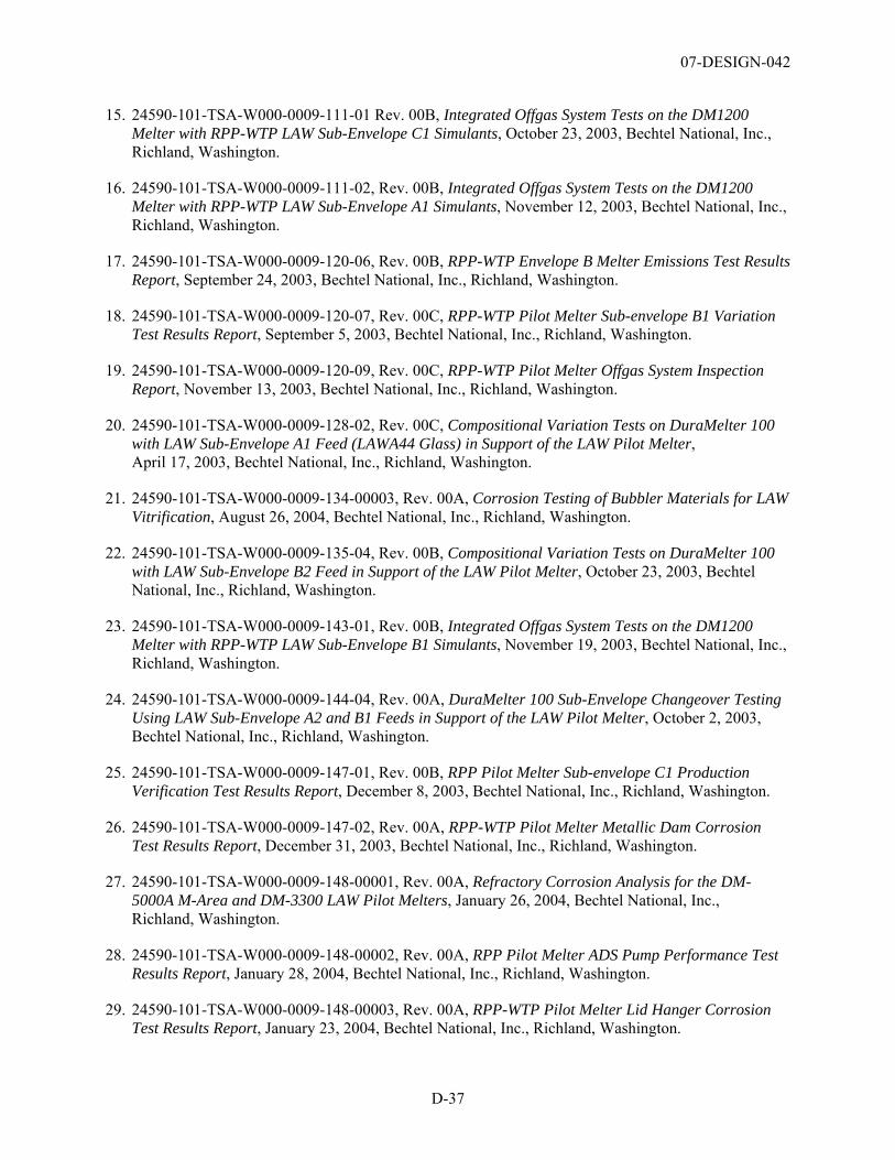
07-DESIGN-042
D-37
15. 24590-101-TSA-W000-0009-111-01 Rev. 00B, Integrated Offgas System Tests on the DM1200 Melter with RPP-WTP LAW Sub-Envelope C1 Simulants, October 23, 2003, Bechtel National, Inc., Richland, Washington.
16. 24590-101-TSA-W000-0009-111-02, Rev. 00B, Integrated Offgas System Tests on the DM1200 Melter with RPP-WTP LAW Sub-Envelope A1 Simulants, November 12, 2003, Bechtel National, Inc., Richland, Washington.
17. 24590-101-TSA-W000-0009-120-06, Rev. 00B, RPP-WTP Envelope B Melter Emissions Test Results Report, September 24, 2003, Bechtel National, Inc., Richland, Washington.
18. 24590-101-TSA-W000-0009-120-07, Rev. 00C, RPP-WTP Pilot Melter Sub-envelope B1 Variation Test Results Report, September 5, 2003, Bechtel National, Inc., Richland, Washington.
19. 24590-101-TSA-W000-0009-120-09, Rev. 00C, RPP-WTP Pilot Melter Offgas System Inspection Report, November 13, 2003, Bechtel National, Inc., Richland, Washington.
20. 24590-101-TSA-W000-0009-128-02, Rev. 00C, Compositional Variation Tests on DuraMelter 100 with LAW Sub-Envelope A1 Feed (LAWA44 Glass) in Support of the LAW Pilot Melter, April 17, 2003, Bechtel National, Inc., Richland, Washington.
21. 24590-101-TSA-W000-0009-134-00003, Rev. 00A, Corrosion Testing of Bubbler Materials for LAW Vitrification, August 26, 2004, Bechtel National, Inc., Richland, Washington.
22. 24590-101-TSA-W000-0009-135-04, Rev. 00B, Compositional Variation Tests on DuraMelter 100 with LAW Sub-Envelope B2 Feed in Support of the LAW Pilot Melter, October 23, 2003, Bechtel National, Inc., Richland, Washington.
23. 24590-101-TSA-W000-0009-143-01, Rev. 00B, Integrated Offgas System Tests on the DM1200 Melter with RPP-WTP LAW Sub-Envelope B1 Simulants, November 19, 2003, Bechtel National, Inc., Richland, Washington.
24. 24590-101-TSA-W000-0009-144-04, Rev. 00A, DuraMelter 100 Sub-Envelope Changeover Testing Using LAW Sub-Envelope A2 and B1 Feeds in Support of the LAW Pilot Melter, October 2, 2003, Bechtel National, Inc., Richland, Washington.
25. 24590-101-TSA-W000-0009-147-01, Rev. 00B, RPP Pilot Melter Sub-envelope C1 Production Verification Test Results Report, December 8, 2003, Bechtel National, Inc., Richland, Washington.
26. 24590-101-TSA-W000-0009-147-02, Rev. 00A, RPP-WTP Pilot Melter Metallic Dam Corrosion Test Results Report, December 31, 2003, Bechtel National, Inc., Richland, Washington.
27. 24590-101-TSA-W000-0009-148-00001, Rev. 00A, Refractory Corrosion Analysis for the DM-5000A M-Area and DM-3300 LAW Pilot Melters, January 26, 2004, Bechtel National, Inc., Richland, Washington.
28. 24590-101-TSA-W000-0009-148-00002, Rev. 00A, RPP Pilot Melter ADS Pump Performance Test Results Report, January 28, 2004, Bechtel National, Inc., Richland, Washington.
29. 24590-101-TSA-W000-0009-148-00003, Rev. 00A, RPP-WTP Pilot Melter Lid Hanger Corrosion Test Results Report, January 23, 2004, Bechtel National, Inc., Richland, Washington.
07-DESIGN-042
D-38
30. 24590-101-TSA-W000-0009-157-00001, Rev. 00A, Final Report – DM100 HLW and LAW Tests of the Influence of Technetium on Cesium Volatility Using Rhenium as a Technetium Surrogate, October 15, 2004, Bechtel National, Inc., Richland, Washington.
31. 24590-101-TSA-W000-0009-162-00001, Rev. 00A, Investigation of Glass Bubbling and Increased Production Rate (Proprietary Data), October 28, 2004, Bechtel National, Inc., Richland, Washington.
32. 24590-101-TSA-W000-0009-166-00001, Rev. 00B, Regulatory Offgas Emissions Testing on the DM1200 Melter System Using HLW and LAW Simulants, November 11, 2005, Bechtel National, Inc., Richland, Washington.
33. 24590-101-TSA-W000-0009-171-00001 Rev. 00A, Summary of DM1200 Operation at VSL, October 10, 2006, Bechtel National, Inc., Richland, Washington.
34. 24590-101-TSA-W000-0009-174-00001 Rev. 00A, Summary of DM1200 WESP History and Performance, August 7, 2006, Bechtel National, Inc., Richland, Washington.
35. 24590-101-TSA-W000-0009-177-00001, Rev. 00A., Summary of DM1200 SBS History and Performance, October 10, 2006, Bechtel National, Inc., Richland, Washington.
36. 24590-101-TSA-W000-0009-23-09, Rev. 00C, RPP-WTP Pilot Melter Bubbler Consumable Changeout Box Test Results Report, August 20, 2003, Bechtel National, Inc., Richland, Washington.
37. 24590-101-TSA-W000-0009-23-10, Rev. 00C, RPP-WTP Pilot Melter Bubbler Life Extension Test Results Report, January 7, 2004, Bechtel National, Inc., Richland, Washington.
38. 24590-101-TSA-W000-0009-32-06, Rev. 00B, RPP-WTP Pilot Melter Sub--Envelope C1 Variation Test Results Report, February 10, 2003, Bechtel National, Inc., Richland, Washington.
39. 24590-101-TSA-W000-0009-32-07, Rev. 00B, RPP-WTP Pilot Melter Sub-envelope C2 Variation Test Results Report, March 24, 2003, Bechtel National, Inc., Richland, Washington.
40. 24590-101-TSA-W000-0009-40-00002, Rev. 00A, RPP-WTP Pilot Melter LAW Discharge Heater Corrosion Test Results Report, February 4, 2004, Bechtel National, Inc., Richland, Washington.
41. 24590-101-TSA-W000-0009-41-02, Rev. 00A, RPP-WTP Pilot Melter Sub-envelope A2 Variation Test Results Report, January 21, 2003, Bechtel National, Inc., Richland, Washington.
42. 24590-101-TSA-W000-0009-49-01, Rev. 00F, RPP-WTP Pilot Melter Sub-Envelope A3 Variation Test Results Report, November 21, 2002, Bechtel National, Inc., Richland, Washington.
43. 24590-101-TSA-W000-0009-49-04, Rev. 00B, RPP Pilot Melter Sub-Envelope A2-B1 Changeover Test Results Report, November 11, 2003, Bechtel National, Inc., Richland, Washington.
44. 24590-101-TSA-W000-0009-53-01, Rev. 00E, Compositional Variation Tests on DuraMelter 100 with LAW Sub-Envelope A2 Feed (LAW A88 Glass) in Support of the LAW Pilot Melter, February 26, 2003, Bechtel National, Inc., Richland, Washington.
45. 24590-101-TSA-W000-0009-54-00001, Rev. 00C, Final Report – Submerged Bed Scrubber (SBS): Off-line Component Testing of DM1200 SBS Unit, August 30, 2004, Bechtel National, Inc., Richland, Washington.
07-DESIGN-042
D-39
46. 24590-101-TSA-W000-0009-66-05, Rev. 00B, Test Matrix to Support Property-Composition Model Development for RPP-WTP LAW Glasses, December 16, 2003, Bechtel National, Inc., Richland, Washington.
47. 24590-101-TSA-W000-0009-66-06, Rev. 00B, Compositional Variation Tests on DuraMelter 100 with LAW Sub-Envelope B1 Feed in Support of the LAW Pilot Melter, June 5, 2003, Bechtel National, Inc., Richland, Washington.
48. 24590-101-TSA-W000-0009-68-04, Rev. 00B, RPP-WTP Pilot Melter Sub-Envelope A-1 Variation Test Results Report, May 8, 2003, Bechtel National, Inc., Richland, Washington.
49. 24590-101-TSA-W000-0009-69-03, Rev. 00B, Final Report – LAW Glass formulation to Support AZ-102 Actual Waste Testing, September 30, 2003, Bechtel National, Inc., Richland, Washington.
50. 24590-101-TSA-W000-0009-69-04, Rev. 00B, LAW Glass Formulation to Support AP-101 Actual Waste Testing, September 4, 2003, Bechtel National, Inc., Richland, Washington.
51. 24590-101-TSA-W000-0009-69-05, Rev. 00B, LAW Glass Formulation to Support AZ-101 Actual Waste Testing, October 2, 2003, Bechtel National, Inc., Richland, Washington.
52. 24590-101-TSA-W000-0009-72-00011 Rev. 00B, Letter Report – Summary and Recommendations on Viscosity and Electrical Conductivity Model Forms to Support LAW Vitrification, October 28, 2004, Bechtel National, Inc., Richland, Washington.
53. 24590-101-TSA-W000-0009-72-05, Rev. 00C, Final Report – Regulatory Spike Testing for RPP-WTP LAW and HLW Glasses for Compliance with Land Disposal Restrictions, June 27, 2003, Bechtel National, Inc., Richland, Washington.
54. 24590-101-TSA-W000-0009-72-05, Rev. 00D, Final Report – Regulatory Spike Testing for RPP-WTP LAW and HLW Glasses for Compliance with Land Disposal Restrictions, August 8, 2003, Bechtel National, Inc., Richland, Washington.
55. 24590-101-TSA-W000-0009-84-02, Rev. 00B, RPP-WTP-Pilot Melter Sub-envelope C1-A1 Changeover Test Results Report, October 1, 2003, Bechtel National, Inc., Richland, Washington.
56. 24590-101-TSA-W000-0009-87-00019, Rev. 00A, Summary Report – Comparison of Offgas Emissions from Tests with LAW Simulants on the DM100, DM1200, and DM3300 Melters, April 28, 2004, Bechtel National, Inc., Richland, Washington.
57. 24590-101-TSA-W000-0009-87-09, Rev. 00B, Off-line Tests of the DM 1200 Thermal Catalytic Oxidation (TCO) Unit, April 17, 2003, Bechtel National, Inc., Richland, Washington.
58. 24590-101-TSA-W000-0009-96-02, Rev. 00B, RPP-WTP Pilot Melter Glass Pool Foaming Control Test Results Report, November 18, 2003, Bechtel National, Inc., Richland, Washington.
59. 24590-101-TSA-W000-0009-96-03, Rev. 00C, RPP-WTP Pilot Melter Sub-Envelope B2 Variation Test Results Report, October 31, 2003, Bechtel National, Inc., Richland, Washington.
60. 24590-101-TSA-W000-0009-98-06, Rev. 00A, Compositional Variation Tests on DuraMelter 100 with LAW Sub-Envelope C1 Feed (LAWC22 Glass) in Support of the LAW Pilot Melter, December 13, 2002, Bechtel National, Inc., Richland, Washington.
07-DESIGN-042
D-40
61. 24590-CM-POA-AELE-00009-01-00001 to 00048, LA-ICP-AES Prototype Design, November 2, 2006, Bechtel National, Inc., Richland, Washington.
62. 24590-LAB-3PS-AELE-T0002, Rev. 0, Engineering Specification for Inductively Coupled Plasma Atomic Emission Spectrometer with Laser Ablation (Prototype), October 24, 2005, Bechtel National, Inc., Richland, Washington.
63. 24590-LAB-3YD-AHL-00001, Rev. 1, System Description for the Analytical Hotcell Laboratory Equipment (AHL), August 5, 2005, Bechtel National, Inc., Richland, Washington.
64. 24590-LAB-3YD-ARL-00001, Rev. 1, System Description for the Analytical Radiological Laboratory Equipment (ARL), February 3, 2005, Bechtel National, Inc., Richland, Washington.
65. 24590-LAW-3PS-HCHH-T0002, Engineering Specification for Special Inert Fill Hoppers – Low Activity Waste Vitrification Facility, September 18, 2003, Bechtel National, Inc., Richland, Washington.
66. 24590-LAW-3PS-HCTH-T0001, Engineering Specification for LAW Product Container Lidding Equipment, February 16, 2006, Bechtel National, Inc., Richland, Washington.
67. 24590-LAW-3PS-HDYR-T0001, Engineering Specification for Power Manipulators and Turntables – Low Activity Waste Vitrification Facility, July 11, 2005, Bechtel National, Inc., Richland, Washington.
68. 24590-LAW-3PS-M000-T0006, Engineering Specification for Shard Sampling System – Low Activity Waste Vitrification Facility, May 6, 2004, Bechtel National, Inc., Richland, Washington.
69. 24590-LAW-3YD-LFH-00001, Rev. 1, System Description for System LFH – LAW Container Finishing Handling System, October 13, 2006, Bechtel National, Inc., Richland, Washington.
70. 24590-LAW-3YD-LFP-00001, Rev. 1, System Description for the LAW Melter Feed Process (LFP) System, June 6, 2005, Bechtel National, Inc., Richland, Washington.
71. 24590-LAW-3YD-LMP-00001, Rev. 1, System Description for the LAW Melter Process System (LMP), November 9, 2005, Bechtel National, Inc., Richland, Washington.
72. 24590-LAW-3YD-LOP-00001, Rev. 1, System Description for the LAW Primary Offgas Process (LOP) and Secondary Offgas Vessel Vent Process (LVP) Systems, March 23, 2005, Bechtel National, Inc., Richland, Washington.
73. 24590-LAW-RPT-PO-05-0001, Rev. 0, LAW Reliability, Availability, and Maintainability Data Development Report, June 8, 2005, Bechtel National, Inc., Richland, Washington.
74. 24590-QL-HC4-HAHH-0001-06-00016 through 00030, Autosampling System ASX-SMPLR, November 17, 2004, Bechtel National, Inc., Richland, Washington.
75. 24590-QL-MRA-AELE-00009-S0001, Materials Requisition Supplement: ICP AES for 222S, LA-ICP-AES Glovebox for 222S, and Laser Ablation System for 222S, March 23, 2005, Bechtel National, Inc., Richland, Washington.
07-DESIGN-042
D-41
76. 24590-QL-POA-MFAO-00001-10-00001, Rev. 00B, Laboratory Test Report: HLW Melter Feed Preparation Vessel and HLW Melter Feed Vessel Agitators, April 3, 2004, Bechtel National, Inc., Richland, Washington.
77. 24590-WTP-3DP-G04B-00027, Rev. 8, Design Verification, September 15, 2006, Bechtel National, Inc., Richland, Washington.
78. 24590-WTP-3DP-G04B-00046, Rev. 16, Engineering Drawings, November 7, 2006, Bechtel National, Inc., Richland, Washington.
79. 24590-WTP-3DP-G04T-00901, Rev. 10, Design Change Control, April 25, 2006, Bechtel National, Inc., Richland, Washington.
80. 24590-WTP-3DP-G04T-00913, Rev. 5, Review of Engineering Documents, August 28, 2006, Bechtel National, Inc., Richland, Washington.
81. 24590-WTP-3PS-MHSS-T0002, Rev. 0, Engineering Specification for the Autosampling System (ASX), June 16, 2004, Bechtel National, Inc., Richland, Washington.
82. 24590-WTP-3YD-ASX-00001, Rev. A, System Description for the Autosampling System (ASX), April 10, 2002, Bechtel National, Inc., Richland, Washington.
83. 24590-WTP-CE-PC-06-001, Rev. 0, WTP Project Estimate at Completion, May 31, 2006, Bechtel National, Inc., Richland, Washington.
84. 24590-WTP-DB-ENG-01-001, Rev. 1C, WTP Basis of Design, November 1, 2006, Bechtel National, Inc., Richland, Washington.
85. 24590-WTP-PL-MG-01-002, Rev. 4, WTP Configuration Management Plan, May 16, 2006, Bechtel National, Inc., Richland, Washington.
86. 24590-WTP-PL-RT-01-002, Rev. 2, WTP Research and Technology (R&T) Program Plan, April 20, 2004, Bechtel National, Inc., Richland, Washington.
87. 24590-WTP-PSAR-ESH-01-002-03, Rev. 1, Preliminary Safety Analysis Report to Support Construction Authorization; LAW Facility Specific Information, September 30, 2003, Bechtel National, Inc., Richland, Washington.
88. 24590-WTP-RPT-OP-01-001, Rev. 2, Operations Requirements Document, May 5, 2003, Bechtel National, Inc., Richland, Washington.
89. 24590-WTP-RPT-PO-05-001, Rev. 0, 2005 WTP Operation Research Assessment , August 29, 2005, Bechtel National, Inc., Richland, Washington.
90. 24590-WTP-RPT-PO-05-008, Rev. 0, 2005 WTP Tank Utilization Assessment, August 8, 2005, Bechtel National, Inc., Richland, Washington.
91. 24590-WTP-RPT-PO-05-009, Rev. 0, 2005 WTP Material Balance and Process Flowsheet Assessment, November 10, 2005, Bechtel National, Inc., Richland, Washington.
92. 24590-WTP-RPT-PR-01-006, Rev. 13, Risk Assessment Report, dated May 31, 2006, Bechtel National, Inc., Richland, Washington.
07-DESIGN-042
D-42
93. 24590-WTP-RPT-PR-01-006, WTP Risk Management Plan, dated May 31, 2006, Bechtel National, Inc., Richland, Washington.
94. 24950-QL-HC4-HAHH-00001-12-00001, Rev. 00B, WTP Autosampling System Reliability Assessment, December 11, 2004, Bechtel National, Inc., Richland, Washington.
95. 24950-QL-HC4-HAHH-00001-12-0001, WTP Autosampling System: Autosampling System Operator Manual, December 20, 2004, Bechtel National, Inc., Richland, Washington.
96. 24950-QL-HC4-W000-00011-03-00481, Rev. 00A, LAW Melter Failure Modes and Effects Analysis, May 10, 2004, Bechtel National, Inc., Richland, Washington.
97. CCN: 078791, “Consideration on Melter Materials,” letter dated February 24, 2005, Bechtel National, Inc., Richland, Washington. .
98. CCN: 128559, “White Paper on the Analysis of Naphthalene Destruction and Removal Efficiency (DRE) Testing at the Vitreous State Laboratory (VSL),” letter dated December 15, 2005, Bechtel National, Inc., Richland, Washington.
99. CCN: 139427, “Waste Treatment and Immobilization Plant/222-S Laboratory Task Plan,” letter dated April 17, 2006, Bechtel National, Inc., Richland, Washington.
100. CCN: 150410, “LAW Melter Bubbler Materials,” letter dated January 23, 2007, Bechtel National, Inc., Richland, Washington.
101. DOE O 413.3A, Program and Project Management for the Acquisition of Capital Assets, July 28, 2006, U.S. Department of Energy, Washington, D.C.
102. DE-AC27-01RL14136, “Waste Treatment and Immobilization Plant Contract,” December 1, 2005, Bechtel National, Inc., Richland, Washington.
103. NHC-8373, The Interlaboratory Pneumatic Transfer Network for Radioactive Samples Operated in the Analytical Laboratories of the COGEMA La Hague Reprocessing Plants (France), Numatec Hanford Company, Richland, Washington, June 1, 2001, Bechtel National, Inc., Richland, Washington.
104. NHC-8374, The Computerized Data Management System Operated in the Analytical Laboratories of the COGEMA La Hague Reprocessing Plants (France), Numatec Hanford Company, Richland, Washington, June 1, 2001, Bechtel National, Inc., Richland, Washington.
105. NHC-8375, Analysis Operating Times Observed in the Analytical Laboratories of the COGEMA La Hague Reprocessing Plants (France), Numatec Hanford Company, Richland, Washington, June 1, 2001, Bechtel National, Inc., Richland, Washington.
106. SCT-M0SRLE60-00-110-12, Rev. 00B, LAW Radioactive Coupon CO2 Decontamination Test, October 1, 2003, Bechtel National, Inc., Richland, Washington.
107. SCT-M0SRLE60-00-135-02, Rev. 00B, RPP-WTP LAW Melter Offgas Flammability Assessment, November 19, 2003, Bechtel National, Inc., Richland, Washington.
07-DESIGN-042
D-43
108. SCT-M0SRLE60-00-187-02, Rev. 00B; -187-02 Rev. 00C (cleared), Evaluation of Wetting Agents to Mitigate Dusting of Glass-forming Chemicals During Delivery to the Melter Feed Preparation Vessel (U), July 31, 2003, Bechtel National, Inc., Richland, Washington.
109. SCT-M0SRLE60-00-99-07, LAW Vendor Coupon CO2 Blasting Tests, September 5, 2002, Bechtel National, Inc., Richland, Washington.
110. SCT-MOSRLE60-00-216-00001, Rev. A, The Development of Laser Ablation Inductively Coupled Plasma Atomic Emission Spectroscopy for the Analysis of Hanford High Level Waste: Phase I (U), Rev. A, September 27, 2005, Bechtel National, Inc., Richland, Washington.
111. SCT-MOSRLE60-00-216-00002, Rev. 0, “The Development of Laser Ablation Inductively Coupled Plasma Atomic Emission Spectroscopy for the Analysis of Hanford High Level Waste: Phase II (U), Rev. 0, March 9, 2006, Bechtel National, Inc., Richland, Washington.

07-DESIGN-042
Appendix E
Participants in the TRL Assessment

07-DESIGN-042
E-1
Appendix E Participants in the TRL Assessment
Table E.1 provides a list of participants in the Technology Readiness Level Assessment for the Analytical Laboratory (LAB), Balance of Facilities (BOF), and LAW Waste Vitrification Facility for each individual critical system evaluated. The participants are divided into the Assessment Team and the Waste Treatment and Immobilization Plant (WTP) Project Technology and Engineering support teams.
The Assessment Team was compromised of staff and consultants representing the U.S. Department of Energy (DOE), Office of River Protection (ORP) (Hanford Site) and Office of Project Recovery (DOE Headquarters). The Assessment Team was also supported by William Nolte of the Air Force Research Laboratory who developed the TRL Calculator used in this assessment.
The Assessment Team was assisted by WTP Project Technology and Engineering teams comprised of subject matter experts associated with the critical technology elements that were being evaluated. These subject matter experts were either responsible for testing the technologies or incorporating the technology design into the WTP. In general, technology testing is managed by staff from Washington Group International (WGI), and engineering of the systems is managed by staff from Bechtel National, Inc. (BNI).
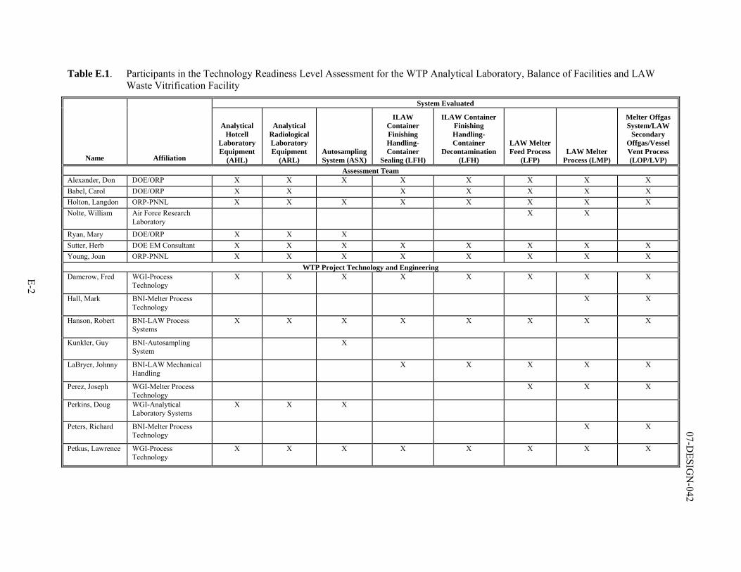
E-2
07-DESIG
N-042
Table E.1. Participants in the Technology Readiness Level Assessment for the WTP Analytical Laboratory, Balance of Facilities and LAW Waste Vitrification Facility
System Evaluated
Name Affiliation
Analytical Hotcell
Laboratory Equipment
(AHL)
Analytical Radiological Laboratory Equipment
(ARL) Autosampling System (ASX)
ILAW Container Finishing Handling-Container
Sealing (LFH)
ILAW Container Finishing Handling-Container
Decontamination (LFH)
LAW Melter Feed Process
(LFP) LAW Melter
Process (LMP)
Melter Offgas System/LAW
Secondary Offgas/Vessel Vent Process (LOP/LVP)
Assessment Team Alexander, Don DOE/ORP X X X X X X X X Babel, Carol DOE/ORP X X X X X X X Holton, Langdon ORP-PNNL X X X X X X X X Nolte, William Air Force Research
Laboratory X X
Ryan, Mary DOE/ORP X X X Sutter, Herb DOE EM Consultant X X X X X X X X Young, Joan ORP-PNNL X X X X X X X X
WTP Project Technology and Engineering Damerow, Fred WGI-Process
Technology X X X X X X X X
Hall, Mark BNI-Melter Process Technology
X X
Hanson, Robert BNI-LAW Process Systems
X X X X X X X X
Kunkler, Guy BNI-Autosampling System
X
LaBryer, Johnny BNI-LAW Mechanical Handling
X X X X X
Perez, Joseph WGI-Melter Process Technology
X X X
Perkins, Doug WGI-Analytical Laboratory Systems
X X X
Peters, Richard BNI-Melter Process Technology
X X
Petkus, Lawrence WGI-Process Technology
X X X X X X X X