Embed Size (px)
Citation preview

TechnologyocusF
Printed & published by Dr Mohinder Singh, Director, DESIDOC, on behalf of DRDO.
RNI No. 55787/93
Readers of Technology Focus are invited to send their communications to the Editor, Technology FocusDESIDOC, Metcalfe House, Delhi - 110 054. India
Telephone: 011-23819975; Fax: 011-23819151; Drona-mail: [email protected]
E-mail: [email protected], [email protected] Internet: http://www.drdo.org/pub/index.shtml; http://www.drdo.com/pub/index.shtml
Technology Focus highlights the technological developments in DRDO, and also covers the products, processes and
technologies.
Dr Mohinder Singh, Director, DESIDOC, Metcalfe House, Delhi
Shri Ajai Kumar, Director of Aeronautics, Sena Bhavan, New Delhi
Dr Harihar Singh, Director of Armaments, Sena Bhavan, New Delhi
Dr JP Agrawal, Director of Materials, Sena Bhavan, New Delhi
Shri A Bhagavathi Rao, Director of Electronics, Sena Bhavan, New Delhi
Shri Gopal Bhushan, SO to SA to RM, South Block, New Delhi
Editors Assistant Editor Design & Pre-press Printing
Ashok Kumar, Vinod Kumari Manoj Kumar Rajesh Kumar JV Ramakrishna, SK Tyagi
Editorial Committee
Editorial Staff
Coordinator
Members
ground in the normal free state mode and has the facility to
mechanically lock at different elevated positions. The
platform also has provision for anchoring radar vehicle
(wheeled/tracked).
Four columns made of large diameter hollow cylindrical
tubes with natural ventilation and staircase for periodical
maintenance supports the platform. The landing at the top of
the platform is fenced in addition to the fencing of the
platform. Lightning arrestors have been provided for entire
platform and radar mounted vehicle. An external staircase
and lift have been provided for smooth movement of
equipment, materials and men. A power/manually operated
hoist has also been provided at the top of the platform to
position the test systems. Power and water required for the
test facility have been provided at the top of the platform
itself. A standby power supply ensures 100 per cent power
availability to the test platform.
This platform is first of its kind in the country and Asia.
Radar test platform
Vol. 11 No. 3 June 2003 ISSN : 0971-4413
BULLETIN OF DEFENCE RESEARCH & DEVELOPMENT ORGANISATION
RADAR TECHNOLOGY
June 2003 7362
TechnologyocusF
TechnologyocusFRadar Technology
forces because of their rugged and compact structure,
high radiation efficiency, and high power handling
capabilities.
DRDO has achieved expertise and core
competence in design, development and fabrication of
slotted waveguide array antenna, which offers ultra
low side lobes for any frequency band. The
electromagnetic modelling technique has been used
to overcome the complex design problems. Several
software packages, viz., COBRAS, COBRAS DC,
COBICS, COBICSNO, LADSOFF, and ANSA with
copyright have been developed for slot characterisation,
linear array design, and array analysis. CAD-based slots
machining and specialised manufacturing technologies
have also been developed.
The antenna has built-in IFF (identification, friend or
foe) facility that uses array of dipoles fed with stripline monopulse comparator and guard channel. It
is being used in major DRDO projects like Tejas (LCA) multimode radar, multibeam surveillance
radar, maritime patrol radar for Naval advanced light helicopter, and battlefield surveillance radar.
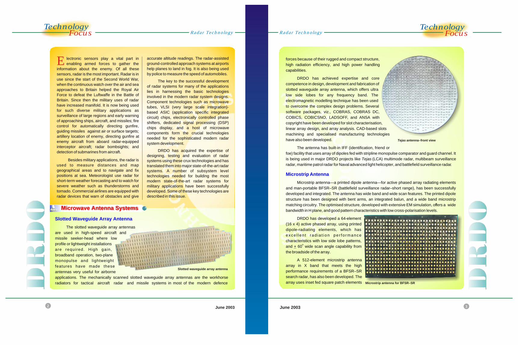
Microstrip antenna—a printed dipole antenna—for active phased array radiating elements
and man-portable BFSR–SR (battlefield surveillance radar–short range), has been successfully
developed and integrated. The antenna has wide band and wide scan features. The printed dipole
structure has been designed with bent arms, an integrated balun, and a wide band microstrip
matching circuitry. The optimised structure, developed with extensive EM simulation, offers a wide
bandwidth in H plane, and good pattern characteristics with low cross-polarisation levels.
DRDO has developed a 64-element
(16 x 4) active phased array, using printed
dipole-radiating elements, which has
exce l l en t r ad ia t i on pe r f o rmance
characteristics with low side lobe patterns, o
and + 60 wide scan angle capability from
the broadside of the array.
A 512-element microstrip antenna
array in X band that meets the high
performance requirements of a BFSR–SR
search radar, has also been developed. The
array uses inset fed square patch elements
Microstrip Antenna
June 2003
Radar Technology
Tejas antenna–front view
E lectronic sensors play a vital part in
enabling armed forces to gather the
information about the enemy. Of all these
sensors, radar is the most important. Radar is in
use since the start of the Second World War,
when the continuous watch over the air and sea
approaches to Britain helped the Royal Air
Force to defeat the Luftwaffe in the Battle of
Britain. Since then the military uses of radar
have increased manifold. It is now being used
for such diverse military applications as
surveillance of large regions and early warning
of approaching ships, aircraft, and missiles; fire
control for automatically directing gunfire,
guiding missiles against air or surface targets;
artillery location of enemy, directing gunfire at
enemy aircraft from aboard radar-equipped
interceptor aircraft; radar bombsights; and
detection of submarines from aircraft.
Besides military applications, the radar is
used to measure distances and map
geographical areas and to navigate and fix
positions at sea. Meteorologist use radar for
short-term weather forecasting and to watch for
severe weather such as thunderstorms and
tornado. Commercial airlines are equipped with
radar devices that warn of obstacles and give
Slotted Waveguide Array Antenna
The slotted waveguide array antennas
are used in high-speed aircraft and
missile seeker-head where low
profile or lightweight installations
are required. High gain,
broadband operation, two-plane
monopulse and lightweight
features have made these
antennas very useful for airborne
applications. The mechanically scanned slotted waveguide array antennas are the workhorse
radiators for tactical aircraft radar and missile systems in most of the modern defence
Microwave Antenna Systems
accurate altitude readings. The radar-assisted
ground-controlled approach systems at airports
help planes to land in fog. It is also being used
by police to measure the speed of automobiles.
The key to the successful development
of radar systems for many of the applications
lies in harnessing the basic technologies
involved in the modern radar system designs.
Component technologies such as microwave
tubes, VLSI (very large scale integration)-
based ASIC (application specific integrated
circuit) chips, electronically controlled phase
shifters, dedicated signal processing (DSP)
chips display, and a host of microwave
components form the crucial technologies
needed for the sophisticated modern radar
system development.
DRDO has acquired the expertise of
designing, testing and evaluation of radar
systems using these crux technologies and has
translated them into major state-of-the-art radar
systems. A number of subsystem level
technologies needed for building the most
modern state-of-the-art radar systems for
military applications have been successfully
developed. Some of these key technologies are
described in this issue.
Microstrip antenna for BFSR–SR
Slotted waveguide array antenna
June 2003June 2003 54
TechnologyocusF
TechnologyocusF
distributed on a small size aperture, and low-loss corporate feed network—the network designed
for a low side lobe Taylor's amplitude distribution. The antenna with backup structure weighs only
1.2 kg.
The active phased
array radar is being used
in ground-based, ship-
borne and airborne
platforms for long
range surveillance
and tracking. The active
phased array technology
overcomes inefficiencies like losses in power dividing/combing field network of conventional
passive phased array, and improves reliability using
transmitter/receiver (T/R) microwave modules. The
technology also significantly improves power efficiency,
low side lobes, and adaptive null placement to counter
jamming.
DRDO has developed the microwave T/R module
element for active phased array using indigenous
technology. The T/R module uses a hybrid microwave
in te gr at ed circuit (MIC) and monolithic microwave integrated circuit
(MMIC) for transmit and receive chains. Both transmit and receive chains are super-
components on two soft ceramic microwave laminates packaged compactly in a
single housing.
Salient Features
High peak power output with a large pulse width and duty over a large RF bandwidth
500 W peak transmit power output in L band
4.5 dB low noise figure over the frequency band
Receive gain : ≥ 35 dB
Receive attenuation : 6-bit
Shared phase shifter : 6-bit
Wide band printed dipole radiator
Distributed beam steering controller
Low loss RF manifold
Thermal management by cold plate technique
Distributed high efficiency flat profile power supplies
Modular concept, extendable to large aperture active arrays
Active Phased Array
Radar TechnologyRadar Technology
T/R module. 64-element array (below left)
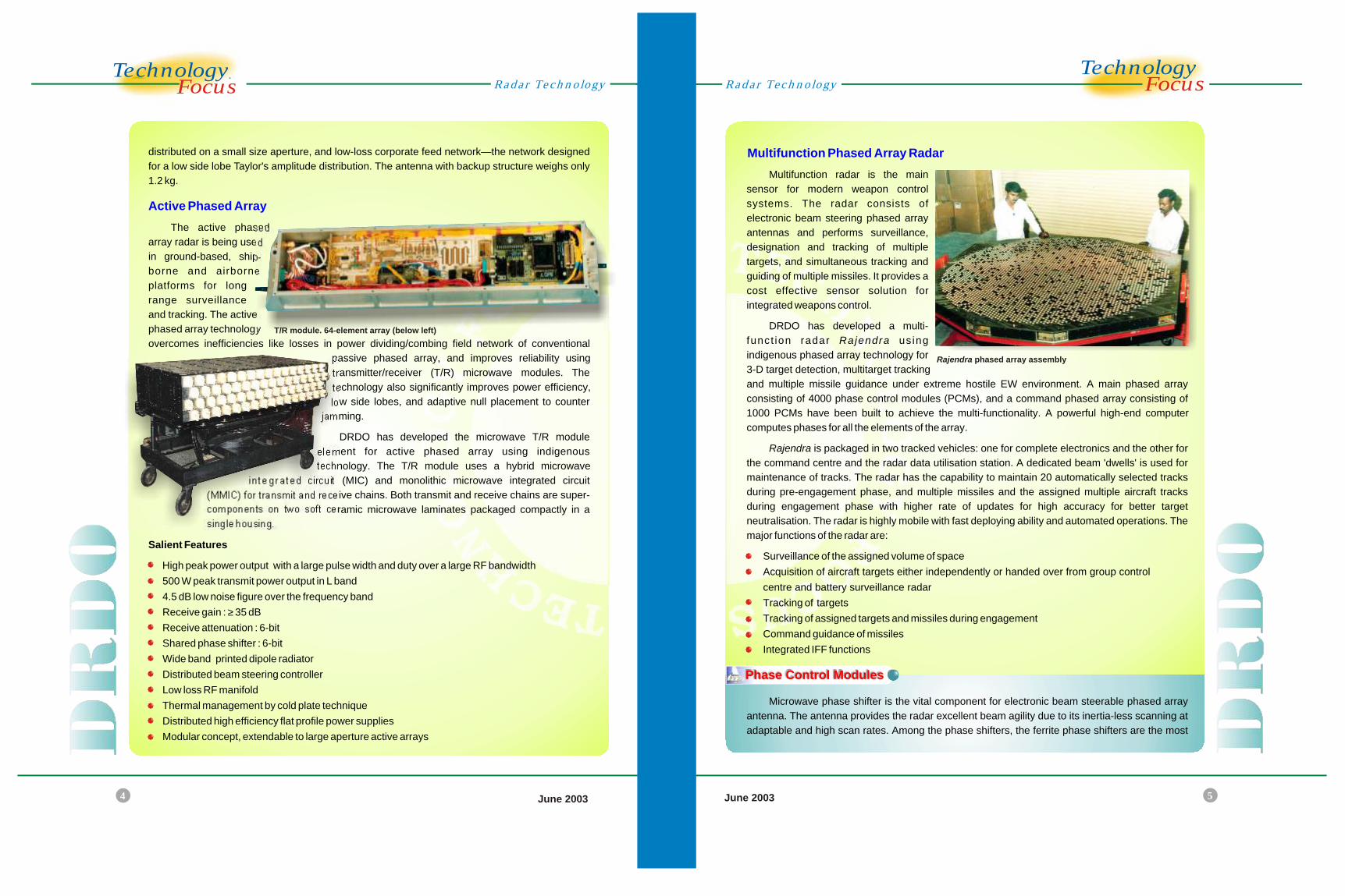
Rajendra phased array assembly
Multifunction Phased Array Radar
Multifunction radar is the main
sensor for modern weapon control
systems. The radar consists of
electronic beam steering phased array
antennas and performs surveillance,
designation and tracking of multiple
targets, and simultaneous tracking and
guiding of multiple missiles. It provides a
cost effective sensor solution for
integrated weapons control.
DRDO has developed a multi-
funct ion radar Rajendra us ing
indigenous phased array technology for
3-D target detection, multitarget tracking
and multiple missile guidance under extreme hostile EW environment. A main phased array
consisting of 4000 phase control modules (PCMs), and a command phased array consisting of
1000 PCMs have been built to achieve the multi-functionality. A powerful high-end computer
computes phases for all the elements of the array.
Rajendra is packaged in two tracked vehicles: one for complete electronics and the other for
the command centre and the radar data utilisation station. A dedicated beam 'dwells' is used for
maintenance of tracks. The radar has the capability to maintain 20 automatically selected tracks
during pre-engagement phase, and multiple missiles and the assigned multiple aircraft tracks
during engagement phase with higher rate of updates for high accuracy for better target
neutralisation. The radar is highly mobile with fast deploying ability and automated operations. The
major functions of the radar are:
Surveillance of the assigned volume of space
Acquisition of aircraft targets either independently or handed over from group control
centre and battery surveillance radar
Tracking of targets
Tracking of assigned targets and missiles during engagement
Command guidance of missiles
Integrated IFF functions
Microwave phase shifter is the vital component for electronic beam steerable phased array
antenna. The antenna provides the radar excellent beam agility due to its inertia-less scanning at
adaptable and high scan rates. Among the phase shifters, the ferrite phase shifters are the most
Phase Control Modules
6
TechnologyocusF
June 2003June 2003
TechnologyocusF
7
Radar TechnologyRadar Technology
High Power Radar Transmitter
power supplies were evolved over long years of working on high voltage power supplies of various
voltage and power levels.
DRDO has developed a technology to build high average power transmitter and expertise in
the weight reduction techniques for minimising the weight and volume of transmitters essential for
airborne application. Indigenous development of transmitters and their integration in the radar have
been completed successfully for Indra I and Indra PC. Both have been inducted into the Services.
Transmitters for Rajendra phased array radar both for search and track, command guidance and
3-D central acquisition radar (CAR) are other major successful developments. The S band 7 kW
transmitter for airborne surveillance platform is another milestone representing a quantum jump in
average power.
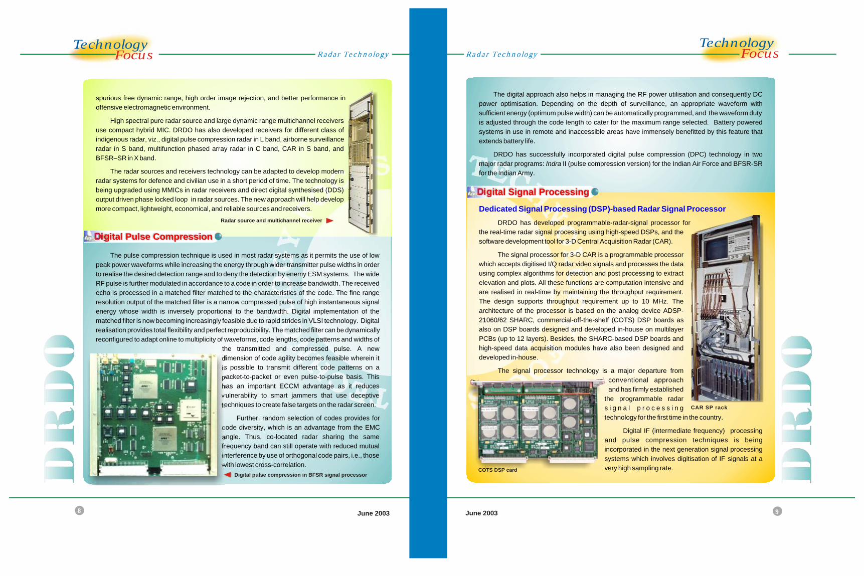
DRDO has developed radar sources for stable
and coherent ultra low phase noise exciter signals for
the radar transmitter, local oscillator signals for the
radar receiver, a large agility bandwidth (>10 per
cent), fast multiple channel switching capability for
effective ECCM, wide band radar waveform
generation (linear FM or digital long length phase
codes), and a high order of spurious/harmonic
rejection. High spectral purity outputs and
improvement in vibration isolation for airborne radar
have been achieved using direct and indirect
frequency synthesis (utilising low noise phased locked
loop schemes), and SC-cut crystal resonators (in lieu
of AT cut type) as the basic reference sources in the frequency synthesisers.
The modern radar receivers are designed to generate ultra low internal noise, achieve
required front-end gain, phase and amplitude stability, high dynamic range, wide band tuning
capability, and protection against saturation
and burnout from nearby interfering radar
transmitters. In addition, multichannel receivers
are required for monopulse tracking and height-
finding 3-D surveillance radar. DRDO has
developed radar receiver technology using
state-of-the-art double superheterodyne
techniques offering features like pulse
compression (digital as well as analog), wide
front-end radar bandwidth with ultra low noise
figures, dual channel monopulse, large
Radar Sources & Receivers
Radar source for Indra
Dual channel radar receiver for Rajendra
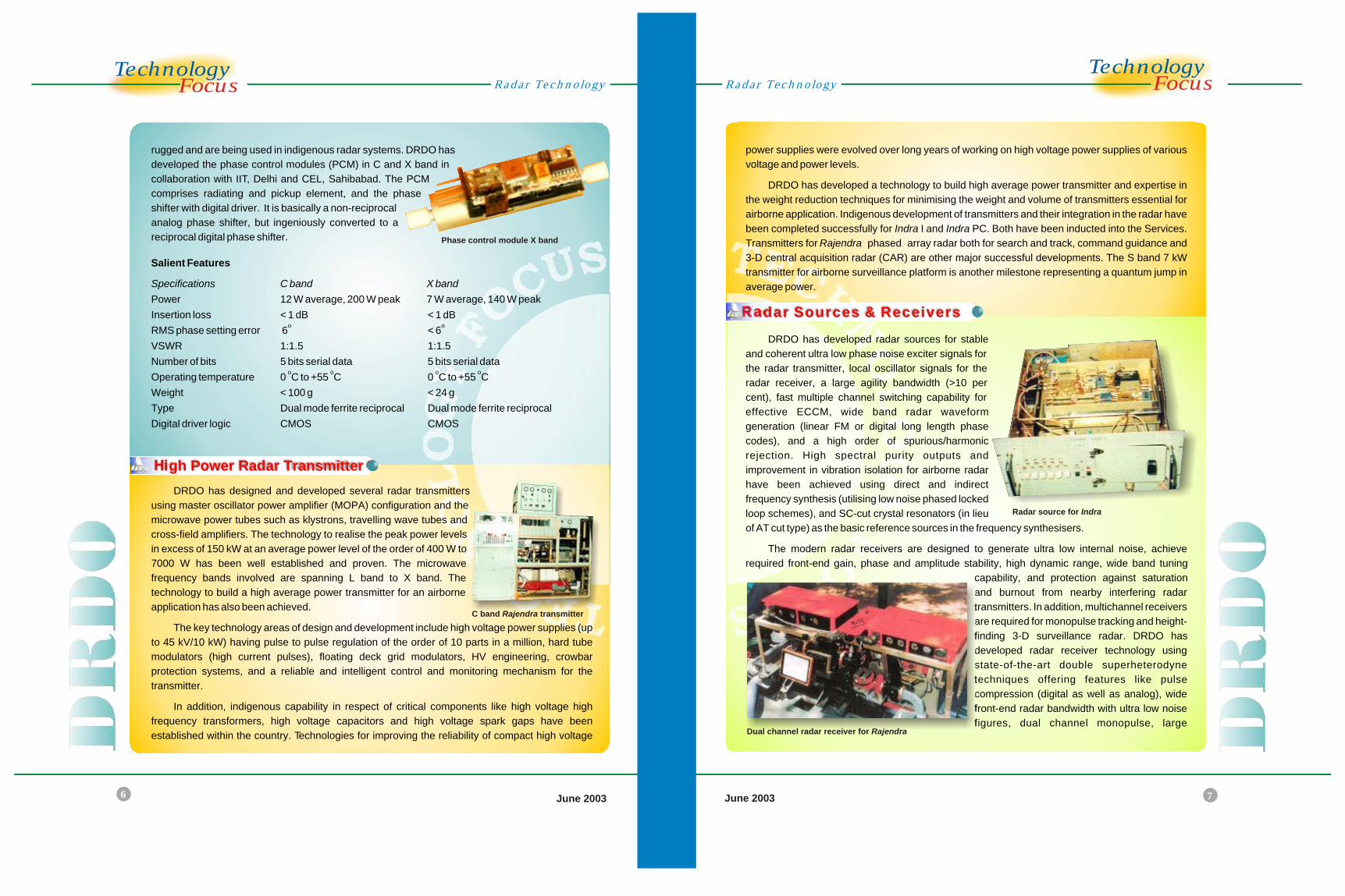
rugged and are being used in indigenous radar systems. DRDO has
developed the phase control modules (PCM) in C and X band in
collaboration with IIT, Delhi and CEL, Sahibabad. The PCM
comprises radiating and pickup element, and the phase
shifter with digital driver. It is basically a non-reciprocal
analog phase shifter, but ingeniously converted to a
reciprocal digital phase shifter.
Salient Features
Specifications C band X band
Power 12 W average, 200 W peak 7 W average, 140 W peak
Insertion loss < 1 dB < 1 dBo o
RMS phase setting error 6 < 6
VSWR 1:1.5 1:1.5
Number of bits 5 bits serial data 5 bits serial datao o o o
Operating temperature 0 C to +55 C 0 C to +55 C
Weight < 100 g < 24 g
Type Dual mode ferrite reciprocal Dual mode ferrite reciprocal
Digital driver logic CMOS CMOS
DRDO has designed and developed several radar transmitters
using master oscillator power amplifier (MOPA) configuration and the
microwave power tubes such as klystrons, travelling wave tubes and
cross-field amplifiers. The technology to realise the peak power levels
in excess of 150 kW at an average power level of the order of 400 W to
7000 W has been well established and proven. The microwave
frequency bands involved are spanning L band to X band. The
technology to build a high average power transmitter for an airborne
application has also been achieved.
The key technology areas of design and development include high voltage power supplies (up
to 45 kV/10 kW) having pulse to pulse regulation of the order of 10 parts in a million, hard tube
modulators (high current pulses), floating deck grid modulators, HV engineering, crowbar
protection systems, and a reliable and intelligent control and monitoring mechanism for the
transmitter.
In addition, indigenous capability in respect of critical components like high voltage high
frequency transformers, high voltage capacitors and high voltage spark gaps have been
established within the country. Technologies for improving the reliability of compact high voltage
Phase control module X band
C band Rajendra transmitter
8
TechnologyocusF
June 2003 June 2003
TechnologyocusF
9
The digital approach also helps in managing the RF power utilisation and consequently DC
power optimisation. Depending on the depth of surveillance, an appropriate waveform with
sufficient energy (optimum pulse width) can be automatically programmed, and the waveform duty
is adjusted through the code length to cater for the maximum range selected. Battery powered
systems in use in remote and inaccessible areas have immensely benefitted by this feature that
extends battery life.
DRDO has successfully incorporated digital pulse compression (DPC) technology in two
major radar programs: Indra II (pulse compression version) for the Indian Air Force and BFSR-SR
for the Indian Army.
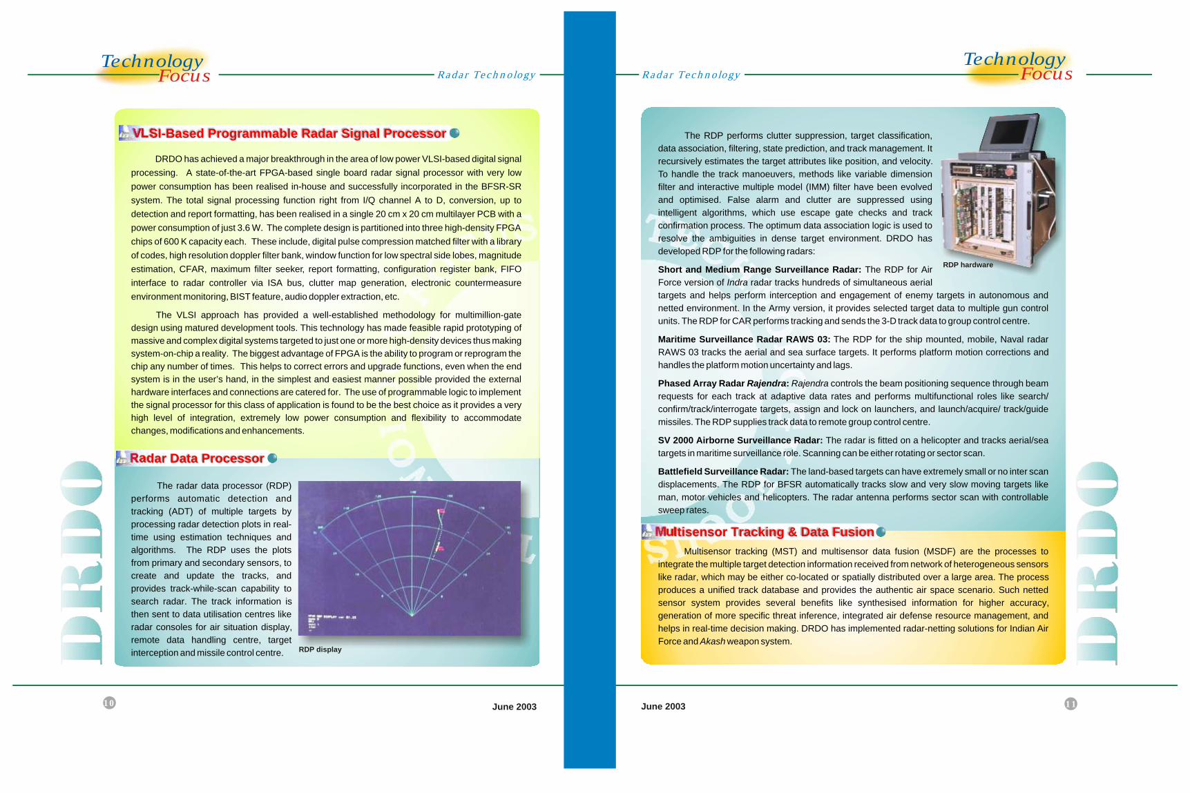
DRDO has developed programmable-radar-signal processor for
the real-time radar signal processing using high-speed DSPs, and the
software development tool for 3-D Central Acquisition Radar (CAR).
The signal processor for 3-D CAR is a programmable processor
which accepts digitised I/Q radar video signals and processes the data
using complex algorithms for detection and post processing to extract
elevation and plots. All these functions are computation intensive and
are realised in real-time by maintaining the throughput requirement.
The design supports throughput requirement up to 10 MHz. The
architecture of the processor is based on the analog device ADSP-
21060/62 SHARC, commercial-off-the-shelf (COTS) DSP boards as
also on DSP boards designed and developed in-house on multilayer
PCBs (up to 12 layers). Besides, the SHARC-based DSP boards and
high-speed data acquisition modules have also been designed and
developed in-house.
The signal processor technology is a major departure from
conventional approach
and has firmly established
the programmable radar
s i g n a l p r o c e s s i n g
technology for the first time in the country.
Digital IF (intermediate frequency) processing
and pulse compression techniques is being
incorporated in the next generation signal processing
systems which involves digitisation of IF signals at a
very high sampling rate.
Dedicated Signal Processing (DSP)-based Radar Signal Processor
spurious free dynamic range, high order image rejection, and better performance in
offensive electromagnetic environment.
High spectral pure radar source and large dynamic range multichannel receivers
use compact hybrid MIC. DRDO has also developed receivers for different class of
indigenous radar, viz., digital pulse compression radar in L band, airborne surveillance
radar in S band, multifunction phased array radar in C band, CAR in S band, and
BFSR–SR in X band.
The radar sources and receivers technology can be adapted to develop modern
radar systems for defence and civilian use in a short period of time. The technology is
being upgraded using MMICs in radar receivers and direct digital synthesised (DDS)
output driven phase locked loop in radar sources. The new approach will help develop
more compact, lightweight, economical, and reliable sources and receivers.
The pulse compression technique is used in most radar systems as it permits the use of low
peak power waveforms while increasing the energy through wider transmitter pulse widths in order
to realise the desired detection range and to deny the detection by enemy ESM systems. The wide
RF pulse is further modulated in accordance to a code in order to increase bandwidth. The received
echo is processed in a matched filter matched to the characteristics of the code. The fine range
resolution output of the matched filter is a narrow compressed pulse of high instantaneous signal
energy whose width is inversely proportional to the bandwidth. Digital implementation of the
matched filter is now becoming increasingly feasible due to rapid strides in VLSI technology. Digital
realisation provides total flexibility and perfect reproducibility. The matched filter can be dynamically
reconfigured to adapt online to multiplicity of waveforms, code lengths, code patterns and widths of
the transmitted and compressed pulse. A new
dimension of code agility becomes feasible wherein it
is possible to transmit different code patterns on a
packet-to-packet or even pulse-to-pulse basis. This
has an important ECCM advantage as it reduces
vulnerability to smart jammers that use deceptive
techniques to create false targets on the radar screen.
Further, random selection of codes provides for
code diversity, which is an advantage from the EMC
angle. Thus, co-located radar sharing the same
frequency band can still operate with reduced mutual
interference by use of orthogonal code pairs, i.e., those
with lowest cross-correlation.
Radar TechnologyRadar Technology
Digital Pulse Compression
Digital Signal Processing
Radar source and multichannel receiver
CAR SP rack
Digital pulse compression in BFSR signal processorCOTS DSP card
DRDO has achieved a major breakthrough in the area of low power VLSI-based digital signal
processing. A state-of-the-art FPGA-based single board radar signal processor with very low
power consumption has been realised in-house and successfully incorporated in the BFSR-SR
system. The total signal processing function right from I/Q channel A to D, conversion, up to
detection and report formatting, has been realised in a single 20 cm x 20 cm multilayer PCB with a
power consumption of just 3.6 W. The complete design is partitioned into three high-density FPGA
chips of 600 K capacity each. These include, digital pulse compression matched filter with a library
of codes, high resolution doppler filter bank, window function for low spectral side lobes, magnitude
estimation, CFAR, maximum filter seeker, report formatting, configuration register bank, FIFO
interface to radar controller via ISA bus, clutter map generation, electronic countermeasure
environment monitoring, BIST feature, audio doppler extraction, etc.
The VLSI approach has provided a well-established methodology for multimillion-gate
design using matured development tools. This technology has made feasible rapid prototyping of
massive and complex digital systems targeted to just one or more high-density devices thus making
system-on-chip a reality. The biggest advantage of FPGA is the ability to program or reprogram the
chip any number of times. This helps to correct errors and upgrade functions, even when the end
system is in the user’s hand, in the simplest and easiest manner possible provided the external
hardware interfaces and connections are catered for. The use of programmable logic to implement
the signal processor for this class of application is found to be the best choice as it provides a very
high level of integration, extremely low power consumption and flexibility to accommodate
changes, modifications and enhancements.
The radar data processor (RDP)
performs automatic detection and
tracking (ADT) of multiple targets by
processing radar detection plots in real-
time using estimation techniques and
algorithms. The RDP uses the plots
from primary and secondary sensors, to
create and update the tracks, and
provides track-while-scan capability to
search radar. The track information is
then sent to data utilisation centres like
radar consoles for air situation display,
remote data handling centre, target
interception and missile control centre.
10
TechnologyocusF
June 2003
TechnologyocusF
11June 2003
The RDP performs clutter suppression, target classification,
data association, filtering, state prediction, and track management. It
recursively estimates the target attributes like position, and velocity.
To handle the track manoeuvers, methods like variable dimension
filter and interactive multiple model (IMM) filter have been evolved
and optimised. False alarm and clutter are suppressed using
intelligent algorithms, which use escape gate checks and track
confirmation process. The optimum data association logic is used to
resolve the ambiguities in dense target environment. DRDO has
developed RDP for the following radars:
Short and Medium Range Surveillance Radar: The RDP for Air
Force version of Indra radar tracks hundreds of simultaneous aerial
targets and helps perform interception and engagement of enemy targets in autonomous and
netted environment. In the Army version, it provides selected target data to multiple gun control
units. The RDP for CAR performs tracking and sends the 3-D track data to group control centre.
Maritime Surveillance Radar RAWS 03: The RDP for the ship mounted, mobile, Naval radar
RAWS 03 tracks the aerial and sea surface targets. It performs platform motion corrections and
handles the platform motion uncertainty and lags.
Phased Array Radar Rajendra: Rajendra controls the beam positioning sequence through beam
requests for each track at adaptive data rates and performs multifunctional roles like search/
confirm/track/interrogate targets, assign and lock on launchers, and launch/acquire/ track/guide
missiles. The RDP supplies track data to remote group control centre.
SV 2000 Airborne Surveillance Radar: The radar is fitted on a helicopter and tracks aerial/sea
targets in maritime surveillance role. Scanning can be either rotating or sector scan.
Battlefield Surveillance Radar: The land-based targets can have extremely small or no inter scan
displacements. The RDP for BFSR automatically tracks slow and very slow moving targets like
man, motor vehicles and helicopters. The radar antenna performs sector scan with controllable
sweep rates.
Multisensor tracking (MST) and multisensor data fusion (MSDF) are the processes to
integrate the multiple target detection information received from network of heterogeneous sensors
like radar, which may be either co-located or spatially distributed over a large area. The process
produces a unified track database and provides the authentic air space scenario. Such netted
sensor system provides several benefits like synthesised information for higher accuracy,
generation of more specific threat inference, integrated air defense resource management, and
helps in real-time decision making. DRDO has implemented radar-netting solutions for Indian Air
Force and Akash weapon system.
Radar TechnologyRadar Technology
VLSI-Based Programmable Radar Signal Processor
Radar Data Processor
Multisensor Tracking & Data Fusion
RDP display
RDP hardware
12
TechnologyocusF
June 2003
TechnologyocusF
13June 2003
Automated Planar Near-Field Measurement (PNFM) Facility
Spherical Near-Field Measurement (SNFM) Facility
Outdoor Antenna Test Range
Radar Test Platform
Near-Field Test Range (NFTR)
The a
(PNFM) is an indoor antenna evaluation facility
that uses planar near-field measurement technique. It
has an indigenously designed and developed 18 m x
12 m x 10 m temperature-controlled anechoic
chamber lined with pyramidal type microwave
absorbers of various sizes on all the sides. The
absorbers are rearranged in a graded fashion for a
quite zone level better than - 40 dB. The scanning
areas of the planar scanner in X, Y, and Z directions
are 10 m x 6 m x 1 m, respectively. The scanner is
controlled by a PLC system operating either in DOS or
Windows environment.
The facility can be used to measure antennas
measuring up to 7 m wide and 4 m high, and a
frequency range of 1 GHz to 18 GHz. The radar
mounted tracked vehicles can be driven inside for
measurement.
Salient Features
Capability to measure antenna with low side lobe up to - 60 dB
Positioning accuracy of scanner in all 3-axis : 300 microns peak
Scientific Atlanta model 1795 microwave receiver with maximum 5000 data samples output
per second
Stable signal source HP 83640A with frequency range 10 MHz to 40 GHz
Indigenously developed software packages for near-field data acquisition, transformation
and result presentation. The output data can be presented in rectangular, 3-D and contour plot
formats
Receiver frequency range : 0.01 GHz to 140 GHz
Automated Planar Near-Field Measurement Facility
utomated planar near-field measurement
facility
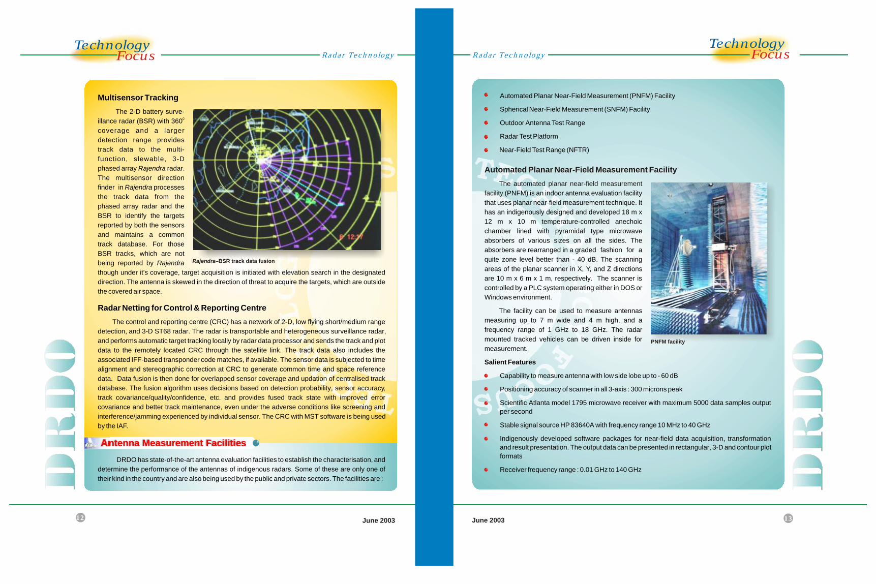
Multisensor Tracking
The 2-D battery surve-0illance radar (BSR) with 360
coverage and a larger
detection range provides
track data to the multi-
function, slewable, 3-D
phased array Rajendra radar.
The multisensor direction
finder in Rajendra processes
the track data from the
phased array radar and the
BSR to identify the targets
reported by both the sensors
and maintains a common
track database. For those
BSR tracks, which are not
being reported by Rajendra
though under it's coverage, target acquisition is initiated with elevation search in the designated
direction. The antenna is skewed in the direction of threat to acquire the targets, which are outside
the covered air space.
Radar Netting for Control & Reporting Centre
The control and reporting centre (CRC) has a network of 2-D, low flying short/medium range
detection, and 3-D ST68 radar. The radar is transportable and heterogeneous surveillance radar,
and performs automatic target tracking locally by radar data processor and sends the track and plot
data to the remotely located CRC through the satellite link. The track data also includes the
associated IFF-based transponder code matches, if available. The sensor data is subjected to time
alignment and stereographic correction at CRC to generate common time and space reference
data. Data fusion is then done for overlapped sensor coverage and updation of centralised track
database. The fusion algorithm uses decisions based on detection probability, sensor accuracy,
track covariance/quality/confidence, etc. and provides fused track state with improved error
covariance and better track maintenance, even under the adverse conditions like screening and
interference/jamming experienced by individual sensor. The CRC with MST software is being used
by the IAF.
DRDO has state-of-the-art antenna evaluation facilities to establish the characterisation, and
determine the performance of the antennas of indigenous radars. Some of these are only one of
their kind in the country and are also being used by the public and private sectors. The facilities are :
Radar TechnologyRadar Technology
Antenna Measurement Facilities
Rajendra–BSR track data fusion
PNFM facility
14
TechnologyocusF
June 2003
TechnologyocusF
15June 2003
Spherical Near-Field Measurement Facility
pherical near-field measurement
facility
Outdoor Antenna Test Range
The automated s
(SNFM) uses SA Model 2022A antenna analyser,
which can be programmed to measure diverse antennas.
A key feature of the SNFM is its capability to perform
measurements in near-field of antenna under test (AUT)
and direct far-field of moderate size antenna. This
enables user to compute near/far-field measurements for
all directions. The SNFM has a computer facility for data
acquisition, transformation and analysis. The facility is
housed in a 18 m x 8 m x 6.5 m shielded microwave
anechoic chamber with all six interior surfaces lined with
pyramidal-shaped absorbing materials to create a quiet
zone of 3 m diameter, reflectivity better than - 50 dB, and
the RF shielding better than 100 dB.
Salient Features
Measurement frequency range : 1 GHz to 18 Ghz
The anechoic chamber houses an optical alignment system and a source tower with
orthomode probe
o oPositional accuracy of the antenna positioner is 0.02 Az, 0.03 roll
oMeasurement accuracy of the SNFM is + 0.5 db in gain, + 1dB at 30 dB in side lobe level, + 0.1
oin beam width, and + 0.1 in null location
The outdoor antenna test range comprises a transmitter
and a receiver located 1.6 km apart from each other. The
transmitter has a parabolic reflector with adjustable height. The
antenna weighing up to one ton mounting facility at the receiver
side on a 3-axis positioner at a height of 21 m from ground can be
tested at the range. A 3-axis positioner can hold a planar antenna
measuring more than 3 m high and 7 m long.
Salient Features
2180SA 100 mw CW power output synthesised sourceo o o
Antenna rotation elevation: - 45 to 90 , upper azimuth: 360 , o
and lower azimuth: +180
The receiving end consists of -100 dBm sensitive 1783 SA
phase and amplitude receiver, and 1580 SA pattern recorder
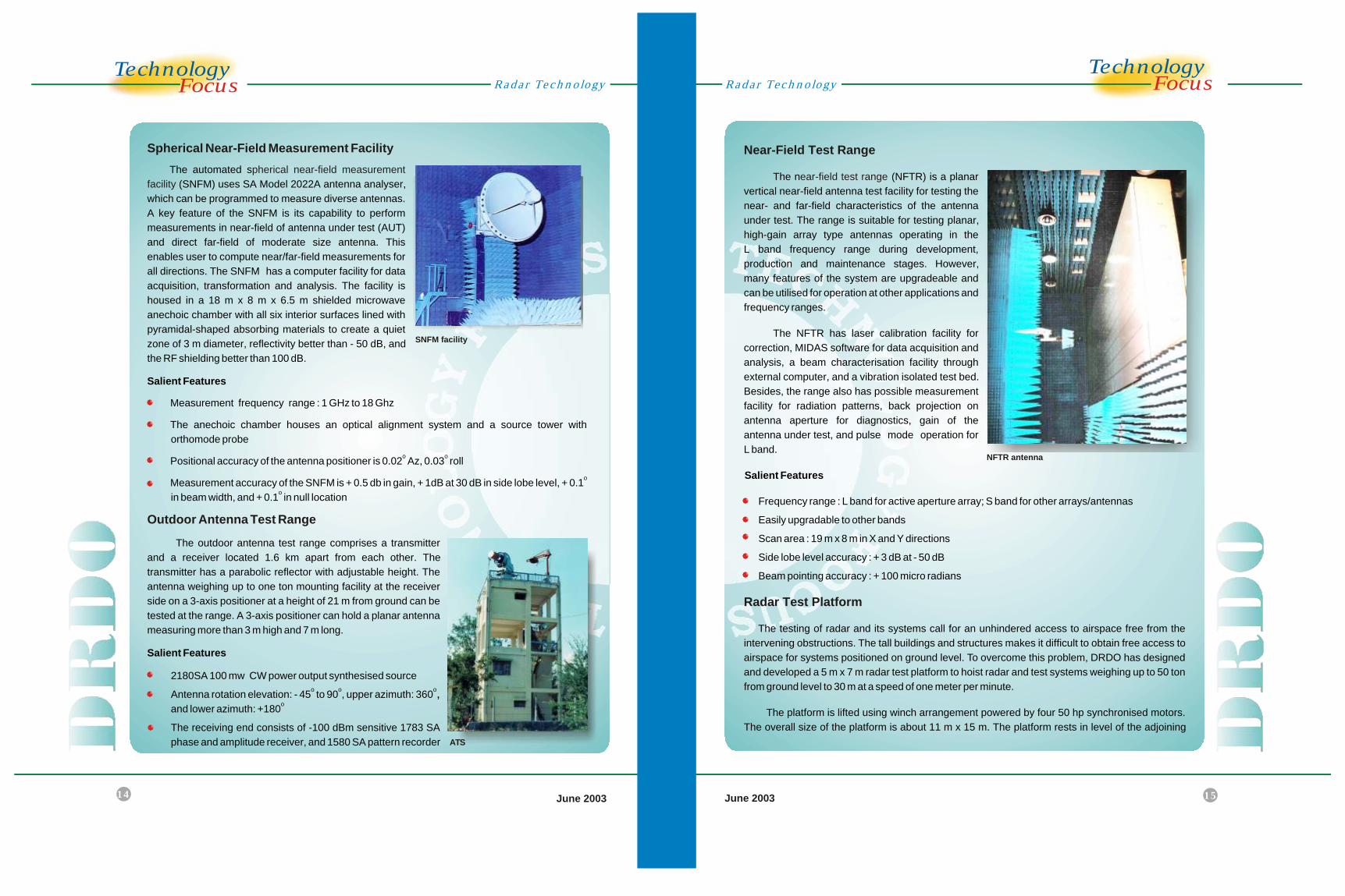
Near-Field Test Range
ear-field test range
Radar Test Platform
The n (NFTR) is a planar
vertical near-field antenna test facility for testing the
near- and far-field characteristics of the antenna
under test. The range is suitable for testing planar,
high-gain array type antennas operating in the
L band frequency range during development,
production and maintenance stages. However,
many features of the system are upgradeable and
can be utilised for operation at other applications and
frequency ranges.
The NFTR has laser calibration facility for
correction, MIDAS software for data acquisition and
analysis, a beam characterisation facility through
external computer, and a vibration isolated test bed.
Besides, the range also has possible measurement
facility for radiation patterns, back projection on
antenna aperture for diagnostics, gain of the
antenna under test, and pulse mode operation for
L band.
Salient Features
Frequency range : L band for active aperture array; S band for other arrays/antennas
Easily upgradable to other bands
Scan area : 19 m x 8 m in X and Y directions
Side lobe level accuracy : + 3 dB at - 50 dB
Beam pointing accuracy : + 100 micro radians
The testing of radar and its systems call for an unhindered access to airspace free from the
intervening obstructions. The tall buildings and structures makes it difficult to obtain free access to
airspace for systems positioned on ground level. To overcome this problem, DRDO has designed
and developed a 5 m x 7 m radar test platform to hoist radar and test systems weighing up to 50 ton
from ground level to 30 m at a speed of one meter per minute.
The platform is lifted using winch arrangement powered by four 50 hp synchronised motors.
The overall size of the platform is about 11 m x 15 m. The platform rests in level of the adjoining
Radar TechnologyRadar Technology
SNFM facility
ATS
NFTR antenna