Embed Size (px)
Citation preview

TECHNOLOGIES FOR PRECISION DOCKING
AT LEVEL-BOARDING PLATFORMS
FOR BUS RAPID TRANSIT SYSTEMS
USING LOW-FLOOR BUSES
A RESEARCH PAPER
SUBMITTED TO THE GRADUATE SCHOOL
IN PARTIAL FULFILLMENT OF THE REQUIREMENTS
FOR THE DEGREE
MASTER OF URBAN AND REGIONAL PLANNING
BY
CODY J. HEDGES
DR. JOHN WEST - ADVISOR
BALL STATE UNIVERSITY
MUNCIE, INDIANA
JULY 2017

2
Table of Contents
Acronyms/Abbreviations .............................................................................................................................. 4
Introduction .................................................................................................................................................. 5
Literature Review ........................................................................................................................................ 10
Magnetic Guidance ..................................................................................................................................... 14
Optical Guidance ......................................................................................................................................... 18
Guide Wheel ............................................................................................................................................... 21
Kassel Kerb .................................................................................................................................................. 23
Guide Strip .................................................................................................................................................. 27
Supplemental Technologies and Driver Training ........................................................................................ 29
Conclusion ................................................................................................................................................... 34
Appendix 1 – Additional Tables .................................................................................................................. 36
Appendix 2 – Lug Nut/Fender Flare Variance ............................................................................................. 37
Appendix 3 – System Interoperability Concerns ......................................................................................... 39
References .................................................................................................................................................. 40
Acknowledgements ..................................................................................................................................... 43
TABLE 1: COMPARISON OF THE FIVE MOST COMMON PRECISION DOCKING TECHNOLOGIES. ......................................... 8
TABLE 2: OPERATOR RESPONSES TO INTERACTION WITH THE MAGNETIC GUIDANCE SYSTEM. (SOURCE: FTA, JANUARY
2016) ................................................................................................................................................... 36
TABLE 3: OPERATIONAL COST OF OPTICAL GUIDANCE SYSTEM IN 2011 IN ROUEN, FRANCE (SOURCE: COWI-SYSTRA,
MAY 2014) ............................................................................................................................................ 36
TABLE 4: LUG NUT AND FENDER FLARE MEASUREMENTS FROM THE INDIANAPOLIS PUBLIC TRANSPORTATION
CORPORATION BUS FLEET, APRIL 2016 (SOURCE: CODY J. HEDGES)................................................................ 37

3
FIGURE 1: MAGNETIC GUIDANCE COMPONENTS. (SOURCE: FTA, JANUARY 2016) .................................................... 15
FIGURE 2: MAGNET IN ROAD. (SOURCE: GRAHAM CAREY) ..................................................................................... 16
FIGURE 3: OPTICAL GUIDANCE SYSTEM IN ROUEN, FRANCE. (SOURCE: WIKIMEDIA COMMONS – SMILEY.TOERIST) ......... 19
FIGURE 4: CLEVELAND GUIDE WHEEL. (SOURCE: FTA, MARCH 2011) ..................................................................... 22
FIGURE 5: KASSEL KERB IN KASSEL, GERMANY (SOURCE: GRAHAM CAREY) ............................................................... 24
FIGURE 6: SELF-POURED KASSEL KERBS IN SAN BERNARDINO, CA. (SOURCE: OMNITRANS VIA MELVIN CABANG) ........... 25
FIGURE 7: POTENTIAL SPECS FOR CHAMPAIGN-URBANA MASS TRANSIT DISTRICT’S KASSEL KERB-STYLE CURB. (SOURCE:
HNTB CORPORATION, SEPTEMBER 2016) .................................................................................................. 26
FIGURE 8: GUIDE STRIPS IN EUGENE, OR. (SOURCE: FTA, MARCH 2011) ................................................................ 28
FIGURE 9: PAINTED BLUE GUIDE STRIPE (LEFT) AND DRIVER ASSIST SYSTEM (DAS) (RIGHT) USED BY GCRTA IN CLEVELAND,
OH. (SOURCE: FTA, MARCH 2011) ........................................................................................................... 30
FIGURE 10: CURB FEELER ON ORANGE LINE BUS IN LOS ANGELES COUNTY, CA. (SOURCE: CARREN JAO VIA ZOCALO PUBLIC
SQUARE, JULY 2, 2012) ........................................................................................................................... 31
FIGURE 11: SPOT MIRROR. (SOURCE: MAGNUM VEHICLE SOLUTIONS) .................................................................... 31
FIGURE 12: CAREY FINGERS (SOURCE: GRAHAM CAREY) ........................................................................................ 32

4
Acronyms/Abbreviations
ADA – Americans with Disabilities Act of 1990 APTS – Advanced Public Transport Systems BRT – Bus Rapid Transit California PATH Program – California Partners for Advanced Transit and Highways Community Transit – Transit Agency for Snohomish County, WA CTfastrak – A regional BRT line operated by CTtransit CTtransit – Transit agency for metropolitan areas of Connecticut CTA – Chicago Transit Authority (Transit agency for Chicago, IL) DAS – Docking Assist System DGPS/INS – Differential Global Positioning System/Inertial Navigation System EmX – Emerald Express (BRT line operated by LTD) FTA – Federal Transit Administration GCRTA – Greater Cleveland Regional Transit Authority (Transit agency for Cleveland, OH) HMI – Human-Machine Interface IndyGo – Indianapolis Public Transportation Corporation (Transit agency for Indianapolis, IN) ITDP – Institute for Transportation and Development Policy KRRI – Korean Railroad Research Institute Loop Link – BRT line operated by CTA LRT – Light Rail Transit LTD – Lane Transit District (Transit agency for Eugene, OR) MARTA – Mécanique Aviation Traction MAX – Metropolitan Area Express (BRT line operated by RTCSNV) Metro Transit – Transit agency for Minneapolis-Saint Paul, MN NACTO – National Association of City Transportation Officials OmniTrans – San Bernardino County Public Transit (Transit agency for San Bernardino, CA) Red Line – BRT line operated by Metro Transit The Rapid – Interurban Transit Partnership (Transit agency for Grand Rapids, MI) RTCSNV – Regional Transportation Commission of Southern Nevada (Transit agency for Las Vegas, NV) sbX – Green Line (BRT line operated by OmniTrans) Swift Blue Line – BRT line operated by Community Transit TCAR – Transports en Commun de l'Agglomération Rouennaise (Transit agency for Rouen, France) TCRP – Transit Cooperative Research Program TEOR – Transport Est-Ouest Rouennais (BRT system operated by TCAR)

5
Introduction
Since the passage of the Americans with Disabilities Act of 1990 (ADA), buses have relied on
bridge plates to allow equal access to passengers with mobility issues.1 However, by limiting the amount
of space between the bus floor and the platform edge, delays that occur through bridge plate
deployment can be eliminated. To achieve this, there are separate platform/vehicle floor alignment
guidelines to which an agency must adhere.2 What would such an adherence mean for a Bus Rapid
Transit (BRT) system’s performance? If BRT systems are to truly perform comparably to Light Rail Transit
(LRT) systems, then this if must no longer be a question. Obtainment of ADA compliant gaps without the
use of a bridge plate should not only be considered, but strived for and achieved. This requires a
mitigation of both the vertical and the horizontal gap between the bus floor and the platform edge.
Before considering the horizontal gap, the vertical gap must be addressed. To avoid the delay
from kneeling a bus, BRT systems utilize platform-level boarding. According to the Institute for
Transportation and Development Policy (ITDP), platform-level boarding occurs when the station
platform is the same height as the bus floor, regardless of height chosen.3 (ITDP, 2014) Once this vertical
gap is minimized, the horizontal gap is addressed through the use of precision docking technologies.
These are technologies that consistently and reliably reduce the horizontal gap between the bus floor
and the station platform when docking. The combination of platform-level boarding and precision
docking significantly reduces dwell time, or the time that a bus spends at a station, by minimizing the
time passengers spend both boarding and alighting. As BRT systems continue to grow and are developed
1 The use of these ramps is outlined in ADA regulation 49 C.F.R. Part 38.23 as “All vehicles covered by this subpart shall provide a level-change mechanism or boarding device (e.g., lift or ramp)…” 2 Outlined in ADA regulation 49 C.F.R. Part 38.53 (d) as “…vehicles shall be coordinated with the boarding platform design such that the horizontal gap between each vehicle door at rest and the platform shall be no greater than 3 inches and the height of the vehicle floor shall be within plus or minus 5⁄8 inch of the platform height under all normal passenger load conditions.” 3 It is important not to confuse platform-level boarding with near-level boarding. The former creates a vertical gap that eliminates the need to step up into the bus, while the later leaves a small vertical gap that requires a step. (APTA, 2010)

6
as viable and equitable alternatives to LRT systems, compliance with this ADA regulation through gap
mitigation and platform-level boarding is a necessity.
At this time, there does not exist a comprehensive evaluation of the existing technologies
available in order to mitigate the size of this horizontal gap. Although guides have been developed, they
often times are either too broad in scope or too limited in their coverage of the technologies. For
instance, the now 14 year-old Transit Cooperative Research Program’s (TCRP) Report 90 gives a fair
assessment of optical guidance, O’Bahn-type systems4, and early magnetic guidance systems, but lacks
information on mechanical systems as discussed in this report. (TCRP, 2003) Meanwhile, the National
Association of City Transportation Officials’ (NACTO) Transit Street Design Guide and the Institute for
Transportation and Development Policy’s (ITDP) BRT Planning Guide and BRT Standard are all useful
guides that recognize precision docking as an important aspect to a BRT system but fail to present
sufficient information to make an informed decision on a specific technology. (ITDP, June, 2007)(ITDP,
2016)(NACTO, 2016) This leaves transit officials, planners, and managers spending unnecessary time
and/or money seeking information independently or enlisting a consultant to prepare a comprehensive
report specifically for their system. Therefore, this report has been created as a resource to provide
assistance to designers, planners, officials, managers, or consultants who are seeking information on the
feasibility of common level boarding technologies within their system, thereby saving both time and
money.
Transit agencies worldwide have primarily implemented one of five technologies for precision
docking which are categorized here as either mechanical or electronic. The two electronic systems are
Optical Guidance and Magnetic Guidance. The three mechanical guidance systems are the Guide Wheel,
Guide Strips, and the Kassel Kerb. This paper will address the performance expectations, cost, and
4 In reading Report 90, it is important to note that it refers to the O’Bahn curb-guided busways as mechanical guidance systems. Although the same terminology is used in this report, they are not the same technologies.
7
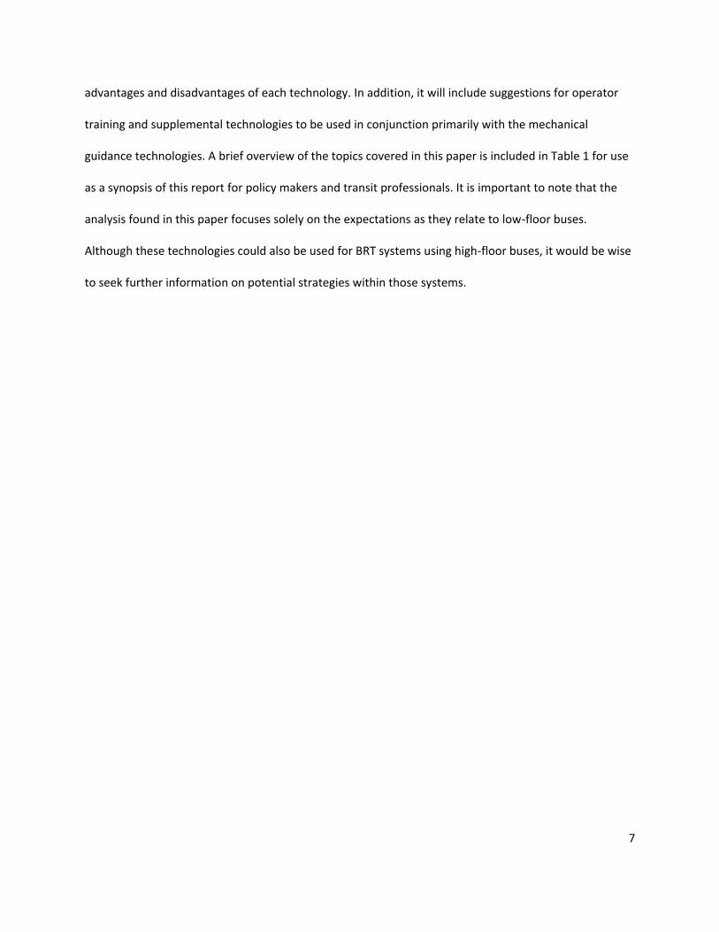
advantages and disadvantages of each technology. In addition, it will include suggestions for operator
training and supplemental technologies to be used in conjunction primarily with the mechanical
guidance technologies. A brief overview of the topics covered in this paper is included in Table 1 for use
as a synopsis of this report for policy makers and transit professionals. It is important to note that the
analysis found in this paper focuses solely on the expectations as they relate to low-floor buses.
Although these technologies could also be used for BRT systems using high-floor buses, it would be wise
to seek further information on potential strategies within those systems.
8
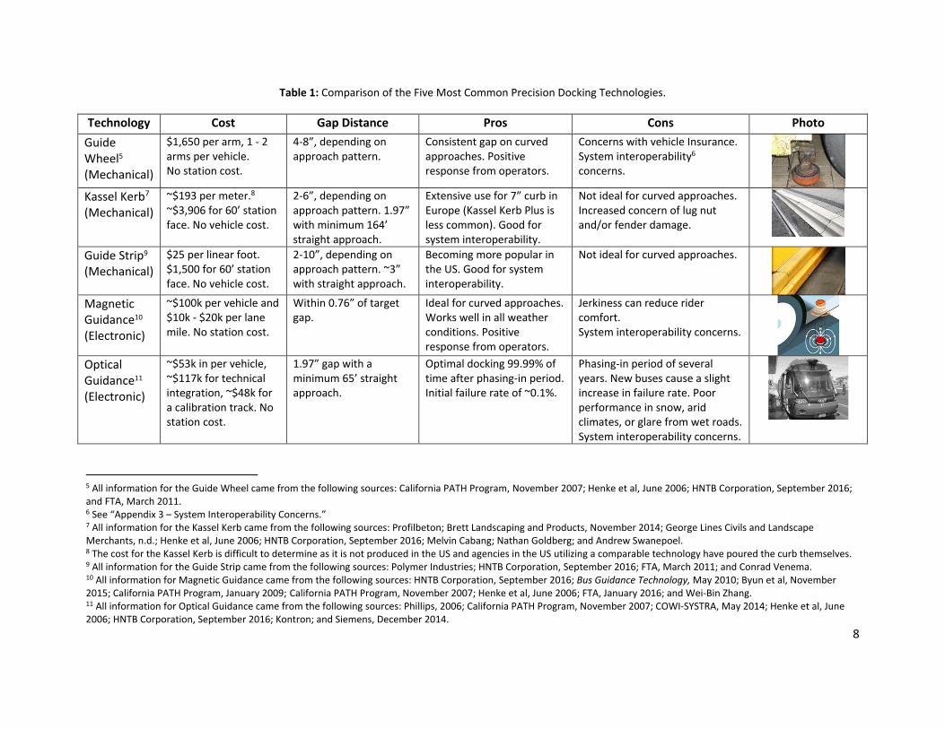
Table 1: Comparison of the Five Most Common Precision Docking Technologies.
Technology Cost Gap Distance Pros Cons Photo
Guide Wheel5 (Mechanical)
$1,650 per arm, 1 - 2 arms per vehicle. No station cost.
4-8”, depending on approach pattern.
Consistent gap on curved approaches. Positive response from operators.
Concerns with vehicle Insurance. System interoperability6 concerns.
Kassel Kerb7 (Mechanical)
~$193 per meter.8 ~$3,906 for 60’ station face. No vehicle cost.
2-6”, depending on approach pattern. 1.97” with minimum 164’ straight approach.
Extensive use for 7” curb in Europe (Kassel Kerb Plus is less common). Good for system interoperability.
Not ideal for curved approaches. Increased concern of lug nut and/or fender damage.
Guide Strip9 (Mechanical)
$25 per linear foot. $1,500 for 60’ station face. No vehicle cost.
2-10”, depending on approach pattern. ~3” with straight approach.
Becoming more popular in the US. Good for system interoperability.
Not ideal for curved approaches.
Magnetic Guidance10 (Electronic)
~$100k per vehicle and $10k - $20k per lane mile. No station cost.
Within 0.76” of target gap.
Ideal for curved approaches. Works well in all weather conditions. Positive response from operators.
Jerkiness can reduce rider comfort. System interoperability concerns.
Optical Guidance11 (Electronic)
~$53k in per vehicle, ~$117k for technical integration, ~$48k for a calibration track. No station cost.
1.97” gap with a minimum 65’ straight approach.
Optimal docking 99.99% of time after phasing-in period. Initial failure rate of ~0.1%.
Phasing-in period of several years. New buses cause a slight increase in failure rate. Poor performance in snow, arid climates, or glare from wet roads. System interoperability concerns.
5 All information for the Guide Wheel came from the following sources: California PATH Program, November 2007; Henke et al, June 2006; HNTB Corporation, September 2016; and FTA, March 2011. 6 See “Appendix 3 – System Interoperability Concerns.” 7 All information for the Kassel Kerb came from the following sources: Profilbeton; Brett Landscaping and Products, November 2014; George Lines Civils and Landscape Merchants, n.d.; Henke et al, June 2006; HNTB Corporation, September 2016; Melvin Cabang; Nathan Goldberg; and Andrew Swanepoel. 8 The cost for the Kassel Kerb is difficult to determine as it is not produced in the US and agencies in the US utilizing a comparable technology have poured the curb themselves. 9 All information for the Guide Strip came from the following sources: Polymer Industries; HNTB Corporation, September 2016; FTA, March 2011; and Conrad Venema. 10 All information for Magnetic Guidance came from the following sources: HNTB Corporation, September 2016; Bus Guidance Technology, May 2010; Byun et al, November 2015; California PATH Program, January 2009; California PATH Program, November 2007; Henke et al, June 2006; FTA, January 2016; and Wei-Bin Zhang. 11 All information for Optical Guidance came from the following sources: Phillips, 2006; California PATH Program, November 2007; COWI-SYSTRA, May 2014; Henke et al, June 2006; HNTB Corporation, September 2016; Kontron; and Siemens, December 2014.

9
The above table compares the five precision docking technologies analyzed in this paper using
costs, gap distance, and their pros and cons for criteria. In terms of cost, the technologies can be
generally divided into high cost and low cost, with the two electronic guidance systems considered high
cost and the three mechanical guidance systems considered low cost. For gap distance, only the guide
wheel was unable to produce a gap compliant with ADA guidelines and therefore is still required to use
a bridge plate at times. Pros and cons can be considered together, first with system interoperability
becoming a concern with the two electronic guidance systems and the guide wheel. For the electronic
systems, this results from financial concerns due to the need to install the technology on non-BRT buses.
For the guide wheel, this is a result of operating concerns of any buses when off the BRT line.12 As
station treatments, neither the Kassel Kerb nor the guide strip have interoperability concerns. However,
appropriate station approach becomes a major issue for these two technologies as they both require a
significant straight line approach in order to perform effectively.
Overall, if finances are not a concern and the area experiences nice weather nearly all year long,
an optical guidance has shown the ability to produce a quality experience. A magnetic guidance system
also shows promise for a quality experience and has not seen the same difficulties with weather.
Additionally, if there are expectations that the system ridership will expand beyond the desired capacity
in the foreseeable future, a magnetic guidance system can support platooning13. (California PATH
Program, January 2009) If financial issues are a concern, then both the Kassel Kerb and guide strips offer
adequate precision docking capabilities. However, as they require straight approaches, space limitations
may create significant problems. In this case, the guide wheel can offer a reliably small gap for able
bodied passengers even with the required curved approaches. A bridge plate would still be required for
12 See “Appendix 3 – System Interoperability Concerns” for further discussion. 13 Platooning occurs when vehicles travel as a single unit. In the case of BRT, this would look and act similar to a multi-car train set commonly seen on LRT systems.

10
passengers with mobility constraints when using the guide wheel, but there exists specially built ramps
which help to reduce the dwell time required by their use. So regardless of what your system requires,
there is a method to produce a precise, satisfactory docking experience.
Literature Review
This paper exists as a comprehensive resource for decision makers on the primary technologies
used for precision docking at level boarding platforms along BRT corridors utilizing low-floor buses. It
assesses the cost, performance, and advantages and disadvantages of five current precision docking
technologies. However, this paper does not contain definitive answers as to what is the “best” or
“worst” technology, as such a determination is impossible given the wide range of project expectations,
needs, and budgets. Instead, this report will allow decision makers to formulate an informed decision on
what technology best fits the needs of their system.
First, it’s important to recognize that although quality BRT guides do exist, they lack a
comprehensive focus on precision docking technologies. For instance, the National Association of City
Transportation Officials’ (NACTO) Transit Street Design Guide, the Institute for Transportation and
Development Policy’s (ITDP) BRT Planning Guide and their BRT Standard, and the Transit Cooperative
Research Program’s (TCRP) Report 90 all fail to provide adequate information for selecting a current
level boarding technology. (ITDP, June, 2007)(ITDP, 2016)(NACTO, 2016)(TCRP, 2003) Although Report
90 gives a fair assessment of early magnetic guidance and optical guidance technologies, due in part to
the age of the document it does not cover several current advancements in the technologies covered in
this report. The NACTO and ITDP guides all present a broad scope that attempts to cover all aspects of a
BRT system. Although they are well developed guides, perhaps due to their broad scope, they present
too little information to make an informed decision on the appropriateness of a given precision docking
11
technology. This document instead focuses on a narrower question asked by transit officials: What
precision docking technology should be utilized on the system I’m building?
Just this question was asked by the Indianapolis Public Transportation Corporation for their
proposed BRT system and was where the need of this report was determined. It was found that
although information was generally available on the different technologies that could be used, it was
scattered and lacked an accessible location where all of this information could be found. And as more
and more agencies in America begin to consider the development of BRT systems, such accessibility is
necessary. The collection of literature here addresses the expected cost, performance, and advantages
and disadvantages of each technology. As adequate literature on all of these topics was not available for
each technology, communication with industry professionals was sought to fill in any gaps in the
research.
The most extensive research and analysis of precision docking technologies in the United States
has come from the FTA and the California Partners for Advanced Transit and Highways (PATH) program.
To start, the magnetic guidance system reviewed in this report was developed by the California PATH
Program and retrofitted to a 60’ BRT bus owned by the Land Transit District (LTD) and placed into
revenue service along their BRT line, the Emerald Express (EmX). Its performance was assessed between
June 2013 and December 2014 by the FTA. (FTA, January, 2016) In a separate report, the FTA evaluated
the performance of the current technology used by LTD along their EmX line, the guide strip. It was a
comparison report between this guide strip and the guide wheel, which is the current technology used
along the Greater Cleveland Regional Transit Authority’s (GCRTA) BRT line, the Healthline. (FTA, March,
2011) However, the guide strip used by LTD is not meant for precision docking but to protect the buses
and stations from damage due to collisions. Therefore, that FTA report is used primarily as a reference
for guide wheel performance expectations and the experiences of the Interurban Transit Partnership
12
(The Rapid) in Grand Rapids, MI along their BRT line, the Silver Line, are considered more relevant to the
potential performance of the guide strip as it was the agency’s aim to use the technology specifically for
precision docking. As there are no papers analyzing the performance of guide strip usage along the Silver
Line, information was gathered directly through communications with officials from the agency.
The successes of the optical guidance system used in Rouen, France has been referenced in
several reports. (COWI-SYSTRA, May 2014)(Henke, Kantor, and Moscoe, June 2006)(California PATH
Program, November 2007)(California PATH Program, January 2009)(TCRP, 2003) A consortium
consultant firm, COWI-SYSTRA, analyzed the performance for gap distance, ridership response, and
costs associated for the technology. (COWI-SYSTRA, May 2014) The problems inherent with the
technology have been noted in several reports and most prevalently through the reports citing the
termination of the technology’s use in Las Vegas, NV due to roadway maintenance costs and issues with
the climate. (Henke, Kantor, and Moscoe, June 2006)(Phillips, 2006)(HNTB Corporation, September,
2016)(UniServices Ltd., July 13, 2016) The Kassel Kerb is widely used in Europe for gap mitigation along
local bus routes. (HNTB Corporation, September 2016) Although primarily used for these lower curbs, it
has been used for precision docking in some American cities such as Las Vegas, NV, although not initially
as the primary technology, and San Bernardino, CA, although more for damage prevention. Due to Buy
America standards, their curbs were self-poured, leaving the potential for wide variability in
performance measurements and expectations. As the level-boarding style of this curb design is simply a
standard height Kassel Kerb with a recessed edge14 and literature specifically on the performance of
level-boarding height Kassel Kerbs was not available, performance measurements and estimated costs
are derived through manufacture specifications for standard curb heights. (Brett Landscaping and
Building Products, November 2014)(George Lines Civils and Landscape Merchants, n.d.)(Caiaffa, M and
14 See “Kassel Kerb” section of this report for more information.

13
Tyler, N, January 1, 1999)(Profilbeton) Additionally, communication with agency officials from the San
Bernardino County Public Transit (OmniTrans) and the Regional Transportation Commission of Southern
Nevada (RTCSNV) where used for comparison.
The last section of this report focuses on supplemental technologies that can be used primarily
in conjunction with the mechanical guidance technologies to help decrease the horizontal gap and
increase operator comfort and consistency. There is very little literature on these technologies and they
are never the focus of the papers in which they appear, although some information on their use was
featured in a 1999 presentation titled Design of Fully Accessible Bus Stops Infrastructure: Elements for
Buses and Drivers, and a March 2011 FTA report titled An Evaluation of the Cleveland Healthline
Mechanical Guide Wheel. Regardless, most of the information on these topics was acquired through
communication with industry professionals. Despite this dearth of readily accessible information, these
technologies can lead to dramatic improvements in performance as was seen along OmniTrans sbX
Green Line15. Much of this ties into increased comfort level of operators. (Melvin Cabang, personal
communication, January 22, 2016)(Dr. Floun’say Caver, personal communication, February 29, 2016)
Therefore, these technologies are intimately tied to operator training. And due to the lack of
information available on supplemental technologies, it is certain that the options presented in this
report should not be taken as an exhaustive list16.
Finally, there are technologies that can be used for precision docking but are not covered in this
report. This is because this report focuses on technologies whose primary purpose is precision docking.
Therefore, unless this is the case and a technology has been used and/or tested as such, it was not
15 Their use of spot mirrors and curb feelers is more thoroughly discussed in the “Supplemental Technologies for Mechanical Docking Technologies and Driver Training” section of this report. 16 In fact, information on the use of spot mirrors, Carey Fingers, and curb feelers was collected entirely by word of mouth. See the “Supplemental Technologies for Mechanical Docking Technologies and Driver Training” section of this report for more information.

14
analyzed in this report. GPS guidance is a technology which has yet to have been tested specifically for
precision docking. It has been tested by Metro Transit in Minneapolis, MN for the operation a 9.5’ wide
coach on a 10’ wide shoulder, particularly under low visibility conditions, and the California Partners in
Advanced Transit and Highways (PATH) program has performed tests to improve GPS technology for
such purposes. (California PATH Program, 2009)(Pessaro, 2013) However, as the tests were not in
revenue service, and therefore not ready for implementation as a precision docking technology, it was
considered outside of the scope of this paper. There are also O’Bahn systems in places such as Leeds,
United Kingdom and Adelaide, Australia. These systems rely on guide wheels to guide the buses along a
concrete track and have not been considered in this report as they are primarily a guideway system and
not a precision docking technology. However, it is important to note that it is from these systems that
the Greater Cleveland Regional Transit Authority (GCRTA) conceived the idea of using a guide wheel
purely for precision docking along the Healthline. (California PATH Program, March 2007) Similar to the
O’Bahn systems, there are the Translohr rail-guided buses seen primarily in France. (TRCP, 2003) These
were considered outside of the scope of this paper as they are primarily a guideway technology and not
a precision docking technology. Lastly, there does exist comparable technologies to the Kassel Kerb in
the Marshall Bus Stop Kerb and the Charcon Access Kerb. However, due to extreme similarities in the
technologies, the prevalence of self-poured curbs in the United States, and the popularity of the Kassel
Kerb, this report focused singularly on the Kassel Kerb. Its analysis is likely comparable to the similar
technologies previously mentioned.
Magnetic Guidance
The magnetic guidance technology reviewed in this report was developed by the California
Partners for Advanced Transit and Highways (PATH) and as completion of this report (June 2017) it is in
the process of being commercialized. This technology uses five (5) key components by which to control

15
the lateral, or side-to-side, position of a vehicle while an operator maintains control of the vehicle’s
speed and braking. A steering actuator physically controls the steering wheel during automated control
without affecting performance while the system is disabled. Magnetic sensors are placed at the front
and the rear of the bus to constantly measure its lateral position with respect to magnetic markers
embedded in the roadway (see Figure 2). A Differential Global Positioning System/Inertial Navigation
System (DGPS/INS) is used as a secondary sensing mechanism and utilizes a yaw rate gyro to measure
the lateral change of the vehicle. These mechanisms continuously calculate the position of the bus and
interact via control computers to determine the accuracy of its location and make needed adjustments
to keep the bus on path. Finally, a Human-Machine Interface (HMI), which are a series of buzzers,
indicators, switches, and buttons, relay relevant information to the driver. A visual breakdown of this
technology can be seen in Figure 1.
Figure 1: Magnetic Guidance Components. (Source: FTA, January 2016)

16
There does exist a separate magnetic guidance technology that, due to its history, needs to be
addressed to avoid potential confusion. It was developed by Frog Navigations and introduced as part of
the Phileas Bus designed by the Advanced Public Transport Systems BV (APTS) of Helmond, The
Netherlands. This technology was developed independently from the PATH system and they are not
interchangeable. The APTS technology was implemented in Eindhoven, The Netherlands; Istanbul,
Turkey; and Douai, France and has since been discontinued due to its failure to meet increasing
European safety standards, a lack of payments due to these failures, and the subsequent bankruptcy of
APTS in 2014. (Erik Van Hal, personal Communications, December 23, 2016)(Van Der Leegte Groep,
2014)(Wei Bin Zhang, personal Communications, May 4, 2016) However, this technology has been
purchased by the Korean Railroad Research Institute (KRRI), presumably for further development in
South Korea as a part of their Bimodal Tram project. (Wei Bin Zhang, personal Communication, May 4,
2016) Therefore, although its performance is not discussed further due to previous struggles, there is
the potential that this technology could reappear in the future.
Figure 2: Magnet in Road. (Source: Graham Carey)
17
Performance
The magnetic guidance technology developed by PATH has been in development and testing
since 1988. In this time, the technology has shown reliability in some of the most extreme weather
conditions. As in 1998 when it was installed as a guidance system on a snowplow used along the Donner
Pass, in which the magnets were able to remain in place an d functional through several freeze/thaw
cycles each year. (California PATH Program, January 2009) Additionally, this technology was retrofitted
to two 40’ New Flyer buses in 2003. In out-of-service demonstrations, therefore without customers,
these buses were able to achieve a consistent horizontal gap of 2 cm (0.79”) in San Diego and
Washington DC. (2009)
A 2016 FTA study reported on the performance of the PATH magnetic guidance system on a 60’
New Flyer bus owned by the Lane Transit District (LTD) in Eugene, OR. In in-service testing, therefore
with customers, along the Emerald Express (EmX) line, LTD’s BRT line, a target gap of 4 cm (1.57”)
between the vehicle floor and the guide strips previously installed at the target stations was sought.
These tests showed a consistently smaller horizontal gap with the magnetic guidance system enabled
than when it was disabled. While enabled, the maximum distance from the target gap was 1.94 cm
(0.76”), compared to a maximum distance when disabled of 11.08 cm (4.36”). (FTA, January 2016)
Cost
As the PATH system has yet to be commercialized, the cost of the technology can only be
estimated. These estimates suggest the cost of retrofitting a bus will be approximately $100,000 per
bus. Additionally, installation of the magnets within the roadway would cost between $10,000 and
$20,000 per lane mile. The majority of the cost related to lane miles is due to the high precision of
surveying needed during installation of the magnets. (Wei Bin Z., personal communication, April 8, 2016)
18
Advantages/Disadvantages
Surveys from the same 2016 FTA report indicated that bus operator perception of the
technology was overwhelmingly positive. Most significantly, operators’ responses indicated a reduced
level of stress and a greater level of safety as they were better able to focus on platform and rider
activity while approaching a station. Further, the consistent performance of the technology led to an
elimination of platform collisions while the technology was enabled, saving money in maintenance
costs. The operators did indicate an initial hesitancy to trust the system and mirrored passenger
responses in that the system felt “jerky” during lane guidance, however, this jerkiness was expressed as
an issue during lane guidance and not during precision docking. (FTA, January 2016) See Table 2 in
Appendix 1 for operator responses to the magnetic guidance system.
Optical Guidance
Optical guidance systems utilize a camera positioned either behind or above the windscreen of a
bus to recognize a particular paint on the roadway and uses this as a means to control lateral
movement, relying on an operator to control speed and braking. (COWI-SYSTRA, May 2014)(TCRP, 2003)
This technology was developed by MARTA17, or Mécanique Aviation Traction, and subsequently
purchased by Siemens, who is currently the only company providing the technology. (California PATH
Program, November 2007)(COWI-SYSTRA, May 2014)
17 There is no connection here between the Mécanique Aviation Traction and the Metropolitan Atlanta Rapid Transit Authority in Atlanta, GA, both who use the acronym MARTA.

19
Figure 3: Optical Guidance System in Rouen, France. (Source: Wikimedia Commons – Smiley.toerist)
Performance
Rouen, France made the decision to implement an optical guidance system in 2001 with the
intent of creating a BRT system, named Transport Est-Ouest Rouennais (TEOR) and operated by
Transports en Commun de l'Agglomération Rouennaise (TCAR), that would achieve the same satisfaction
rates as their Light Rail Transit (LRT) system. The optical guidance technology used along this BRT system
achieves an optimal approach 99.9% of the time. In order to achieve this optimal approach, it requires a
20 m (65.62’) straight alignment approaching each station. Optical guidance systems have a unique
quality in that they improve with time and require a phasing-in period of a few years to reach optimum
performance. This should not be taken to mean that the vehicles perform poorly during this phasing-in
period. In Rouen, the initial failure rate in 2002, the year of implementation, was 1.37 per 1000 station
approaches (99.863% success rate) and leveled out to 0.195 failures per 1000 station approaches
(99.981% success rate) by 2006. (COWI-SYSTRA, May 2014) Although “failure” was not specifically
defined in the COWI-SYSTRA article, Siemens rates the performance of their Optiguide/Optiboard optical
guidance system, which is the system used in Rouen, at maintaining a 50 mm (1.97”) gap between bus
and platform. This suggests that a “failure” would be when a gap greater than 50 mm (1.97”) occurs.
(Kontron)(Siemens, December 2014)(Rouen, France Brief: TEAR Optically Guided Bus) Also note that the

20
introduction of additional buses causes an increase in the failure rate. The arrival of new vehicles in
Rouen in 2007 increased the failure rate to 0.425 per 1000 station approaches (99.958% success rate)
before ultimately leveling out to 0.15 faults per 1000 station approaches (99.985% success rate) by
2011. (COWI-SYSTRA, May 2014)
Cost
The cost of this technology is not precise due to the low number of cases of implementation.
However, Siemens, who is the manufacturer of the technology, projects that is would cost between 2%
and 5% of a new vehicle and is likely around 50,000 € (~$53,000) per vehicle to retrofit. (Siemens,
December 2014)(COWI-SYSTRA, May 2014) The Regional Transportation Commission of Southern
Nevada (RTCSNV) in Las Vegas, NV implemented CIVIS along their Metropolitan Area Express (MAX) BRT
line at a cost of approximately $100,000 per bus to install the technology. (Rouen, France Brief: TEAR
Optically Guided Bus) Technical studies for integration at each station would amount to approximately
110,000 € (~$116,600) for a given line and involves the construction of a calibration track at 45,000 €
(~$47,700). Operationally, Rouen spent 826,000 € (~$875,600) in 2011 with a fleet of 66 equipped
buses. (COWI-SYSTRA, May 2014) A breakdown of these costs can be seen in Table 3 in Appendix 1.
Advantages/Disadvantages
This technology has shown performance difficulties in poor weather conditions. RTCSNV’s now
discounted MAX line discontinued the use of this technology after experiencing disruption problems due
to dirt and oil build up from a lack of rain in the desert climate. (Henke, Kantor, and Moscoe, June 2006)
UniServices Ltd., July 13, 2016) A report from the California PATH Program at UC Berkeley mentioned
the absence of snow in Rouen as a factor in its success and stated that, “[t]he system sometimes cannot
engage when the sun angle is low and pointed toward the bus, as well as in the special condition of glare

21
off wet pavement…There are only a few snowy days per year in Rouen, and drivers are advised to turn
off the system when it is snowing.” (California PATH Program, pg. 9, January 2009)
Surveys of the bus operators in Rouen were found to be generally favorable towards the optical
guidance system. They found the system to be more convenient than doing the docking themselves,
that it relieved them of some of the workload so that they could interact more with the passengers, and
that it helped to reduce their level of stress. (California PATH Program, November 2007) This also helped
lead to an increase in safety as system operators reported that they could, “…devote more attention to
their surroundings, rather than low-level vehicle maneuvering.” (pg. 8, 2007) Ultimately, the use of
optical guidance technology was considered to have achieved the goal set forth in 2001 as passengers
rated the satisfaction of their experience comparable to that of the LRT system also in Rouen. (2007)
Guide Wheel
The guide wheel is a small mechanical wheel attached to the steering axle of a bus. These are
used for guidance along guided busways in Leeds, UK; Essen, Germany; and Adelaide, Australia. The
Greater Cleveland Regional Transit Authority (GCRTA) in Cleveland, OH uses guide wheels solely for
precision docking along their BRT system, known as the Healthline. They are attached to both sides of
the bus as passengers are able to board on either side depending on the location of the stations.
(California PATH Program, January 2009)(Phillips, 2006)(FTA, March 2011)

22
Figure 4: Cleveland Guide Wheel. (Source: FTA, March 2011)
Performance
According to a 2011 FTA report, performance along the route saw an average gap of 8” between
the bus door and the platform on straight approaches and 6.5” on curved approaches18. (FTA, March
2011) These performance measures have not changed since the 2011 report. (Dr. Floun’say Caver,
personal communication, February 29, 2016) Although this does not achieve the gap set forth in ADA
regulation, these gaps are manageable by able-bodied riders and a bridge plate is utilized to bridge the
gap for passengers with mobility challenges.
Cost
The GCRTA spent $3,700 per vehicle, 2 arms per vehicle at $1,650 per arm, for the installation of
the guide wheels. In terms of maintenance costs, GCRTA spent $15,060 in 2009 to repair broken docking
arms for their entire BRT fleet, which covered over 723,000 revenue miles. (FTA, March 2011) The
GCRTA has reported that this cost has since declined due to use of higher quality metal for the arms and
alterations to driver training which has reduced the frequency of arms breakage. Specifics on how much
18 Gap measurements were made from the second door on the left side of the bus, at the forward most side of the doorway. (FTA, March 2011)

23
this cost has declined were not available. (Dr. Floun’say Caver, personal communication, February 29,
2016)
Advantage/Disadvantages
A survey of driver responses to the use of the mechanical arms showed that 80% of Cleveland
operators agreed or strongly agreed that the guide wheel helped them dock more quickly and precisely,
that it was easy to use, and that they would recommend it to other transit agencies. 77% agreed or
strongly agreed that it made docking less stressful. (FTA, March 2011)
When installing the guide wheel, GCRTA was required by New Flyer, the manufacturer of the
BRT buses in their fleet, to void the warranty for the vehicles on which the guide wheels were installed.
GCRTA also had concerns that the arms could cause damage to the axle, so they are designed to break
off prior to such an occurrence. This likely led to the issue of frequent breaking early on and resulted in
the maintenance costs seen in the 2011 FTA report. This frequent breakage also created reliability
concerns as a bus must be removed from service to replace the broken guide wheel, although it
remained otherwise still functional. (Dr. Floun’say Caver, personal communication, February 29, 2016)
Kassel Kerb
The Kassel Kerb is a specially designed curb originally developed in Kassel, Germany. It is a curb
with a beveled edge that bus wheels can safely rub against as they approach a station, leading to a
reduction of the gap between the bus floor and the platform. This technology is widely used across
Europe for standard height curbs, with companies such as Brett Landscaping and Paving manufacturing
in heights of 160mm (6.3”) and 180mm (7.09”). (HNTB Corporation, September 2016)(Brett Landscaping
and Building Products, November 2014) Although these curb heights are not adequate for level

24
boarding, their performance is comparable to Kassel Kerb Plus®-style curbs. These heightened curb
designs increase their heights by using a recessed edge and raising the curb to the desired height, thus
allowing for level boarding (see Figure 5). The recessed edge is a necessary element for level boarding to
avoid damage to lug nuts or fender flares while still being of sufficient height.19 At this time (2017), there
are no manufacturers of this product in the United States, which is important if Buy America standards
apply to a transit project. Often times, this leads to a self-pouring of the curbs, as was done by San
Bernardino County Public Transit (Omnitrans) in San Bernardino, CA along the sbX Green Line and the
Regional Transportation Commission of Southern Nevada’s (RTCSNV) former Metropolitan Area Express
(MAX) line in Las Vegas, NV. (Melvin Cabang, personal communication, January 22, 2016)(Nathan
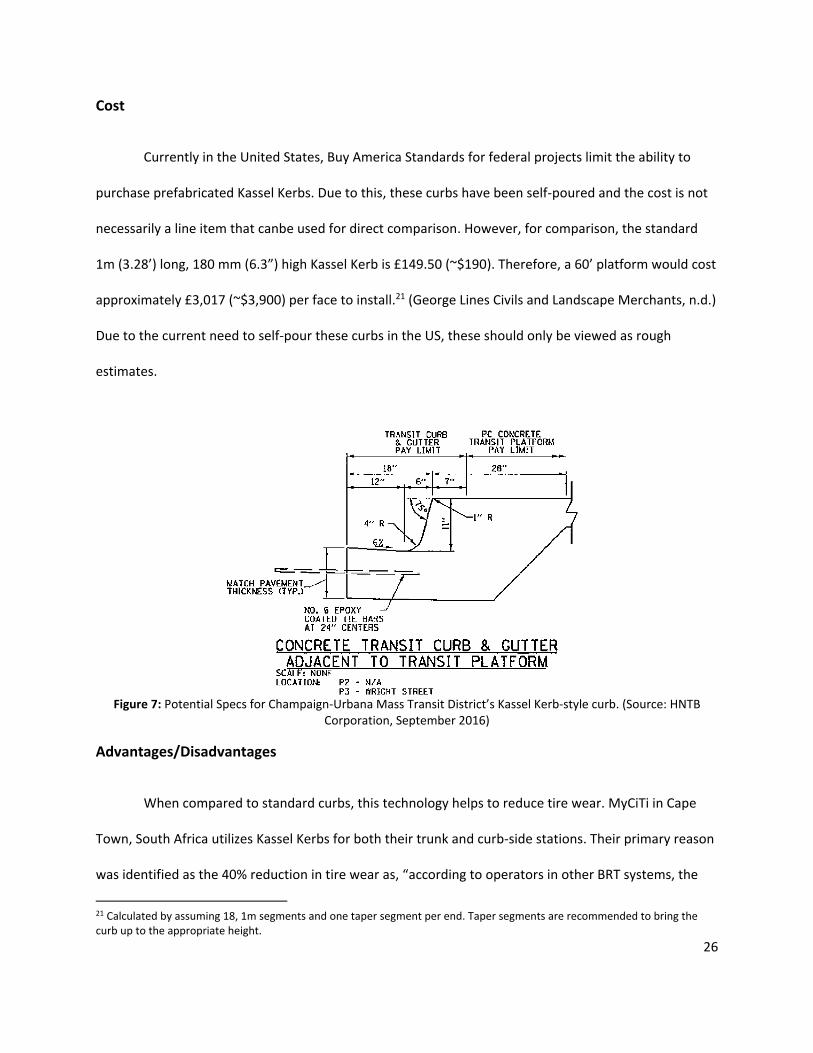
Goldberg, personal communication, March 3, 2016) Additionally, the Champaign-Urbana Mass Transit
District is planning on using a self-poured version of the technology for a proposed BRT corridor in the
city using the schematics seen in Figure 7. (HNTB Corporation, September 2016)
Figure 5: Kassel Kerb in Kassel, Germany (Source: Graham Carey)
19 See “Appendix 2 – Lug Nut/Fender Flare Variance” for a further discussion on this topic.

25
Performance
According to Brett Landscaping, Kassel Kerbs provide for a gap of 50 mm (1.97”) or less. To
achieve this desired gap, a linear approach of no less than 50 m (164.04’) is required. (Brett Landscaping
and Building Products, November 2014) In San Bernardino, the curbs are used primarily to avoid
collision with the platform and were self-poured due to Buy America restrictions. Utilizing supplemental
technologies20 along with the curb, Omnitrans achieves a regular gap of 6”. (Melvin Cabang, personal
communication, January 22, 2016) Therefore, a bridge plate is still required to cover the gap between
the bus and the platform for riders in wheelchairs. Additionally, as no recessed edge was used at their
stations, lug nuts are known to cause damage to the yellow dome pavers used as a warning strip for
passengers. In Las Vegas, RTCSNV implemented sloped curves along their MAX BRT route, although it
was not to be the primary precision docking technology at the time of implementation (as of February
21, 2016, MAX had been discontinued). In order to prevent lug nut damage to their vehicles, each was
equipped with wheel covers. These covers did sustain minor damage from occasional scraping against
the curb. Contractors for RTCSNV, Keolis and MV Transportation, reported that the MAX vehicles were
able to achieve an average gap of 3-4” using the sloped curves (this was after the discontinuation of the
optical guidance system). (Nathan Goldberg, personal communication, March 3, 2016)
Figure 6: Self-Poured Kassel Kerbs in San Bernardino, CA. (Source: Omnitrans via Melvin Cabang)
20 See the “Supplemental Technologies” section for more information.
26
Cost
Currently in the United States, Buy America Standards for federal projects limit the ability to
purchase prefabricated Kassel Kerbs. Due to this, these curbs have been self-poured and the cost is not
necessarily a line item that canbe used for direct comparison. However, for comparison, the standard
1m (3.28’) long, 180 mm (6.3”) high Kassel Kerb is £149.50 (~$190). Therefore, a 60’ platform would cost
approximately £3,017 (~$3,900) per face to install.21 (George Lines Civils and Landscape Merchants, n.d.)
Due to the current need to self-pour these curbs in the US, these should only be viewed as rough
estimates.
Figure 7: Potential Specs for Champaign-Urbana Mass Transit District’s Kassel Kerb-style curb. (Source: HNTB
Corporation, September 2016)
Advantages/Disadvantages
When compared to standard curbs, this technology helps to reduce tire wear. MyCiTi in Cape
Town, South Africa utilizes Kassel Kerbs for both their trunk and curb-side stations. Their primary reason
was identified as the 40% reduction in tire wear as, “according to operators in other BRT systems, the
21 Calculated by assuming 18, 1m segments and one taper segment per end. Taper segments are recommended to bring the curb up to the appropriate height.
27
most expensive operating cost after fuel is the cost of replacing tyres.” (Andrew Swanepoel, personal
communication, February 18, 2016) Although MyCiTi uses high-floor buses, tire wear reduction would
be the same for low-floor buses.
As pointed to earlier, a significant concern with the Kassel Kerb is potential damage to both lug
nuts and fender flares. Unless properly constructed, the curb has the potential to cause significant
damage to both the vehicle and the station and lead to large, unexpected maintenance costs. Also, given
the 50m (164.04’) minimum approach distance, Kassel Kerbs are not ideal corridors requiring curved
approaches.
Guide Strip
Guide strips are typically a polyethylene strip used to guide buses along docking platforms. They
assist in preventing collisions between the bus and the platform by allowing the tires to rub against the
strip. Its use can vary depending on the desires of the transit agency implementing it. The primary
function of guide strips by the Lane Transit District (LTD) in Eugene, OR along their BRT line, the Emerald
Express (EmX), is primarily to prevent damage caused by contact between buses and stations. However,
the Interurban Transit Partnership (The Rapid) in Grand Rapids, MI, uses the technology primarily for
precision docking along their BRT line, the Sliver Line. Additionally, this technology is used along Metro
Transit’s Red Line in the Mineapolis-Saint Paul, MN area, the Chicago Transit Authority’s (CTA) Loop Link
in downtown Chicago, and along Community Transit’s Swift Blue Line in Snohomish County, WA. (HNTB
Corporation, September 2016)

28
Figure 8: Guide Strips in Eugene, OR. (Source: FTA, March 2011)
Performance
According to a 2011 FTA report, the guide strip used by LTD achieved an average gap of 8.5”22
between the door and the platform with straight approaches and 9.75” with curved approaches (FTA,
March 2011). Representative of LTD pointed out that operators have been able to decrease this gap but
did not give specific figures except to say that it is rarely below 6”. (Mark Johnson, personal
communication, February 22, 2016) Remember that LTD uses guide strips for damage control, not
precision docking.
Along The Rapid’s Silver Line, a maximum gap of 3” has been consistently achieved. (Conrad
Venema, personal communication, February 2, 2016)(HNTB Corporation, September 2016) Two factors
have been attributed to leading to this performance: appropriate driver training and a focus on making
approaches to stations as straight as possible. The 3” gap mentioned above is achieved at all but one
station due to a left turn prior to docking. This results in the back door23 being unable to consistently
obtain the 3” gap. However, in the first two years of operation of the Silver Line, deployment of a bridge
plate, which are still installed in their Silver Line buses, has not been needed for accessibility needs.
(Conrad Venema, personal communication, July 19, 2016)
22 Gap measurements were made from the second door on the left side of the bus, at the forward most side of the doorway. (FTA, March 2011) 23 In this case, the back door is the second of two as The Rapid uses 40’ buses for the Silver Line.
29
Cost
LTD spent $2,500 per side per station at $25 per linear foot to install their guide strips (no data
on lifecycle cost was available). In terms of maintenance costs, LTD spent $1,252 in 2009 to replace 6
tires damaged during pull out from stations, which covered 203,699 revenue miles. (FTA, March 2011).
Advantages/Disadvantages
Maintenance costs could be of issue with this technology, as seen with LTD. However, officials
working with The Rapid made no mention of excessive damage to their tires during docking. A possible
explanation here is that the more aggressive turns required during docking approaches in the LTD
system may be a factor. Officials working with The Rapid did note an increased wear due to frequent
rubbing against the guide strips. (Conrad Venema, personal communication, February 2, 2016)
Success with this technology requires careful attention to designing the approach to each
station. In order to obtain the smallest horizontal gap distance, it is essential that the approaches be as
straight as possible. The Rapid is able to achieve their gap due to their emphasis on straight line
approaches. LTD lacked this option due to spatial limitations along their system, likely resulting in the
increased gap found in the 2011 FTA study.
Supplemental Technologies and Driver Training
Supplemental Technologies
There are several supplemental technologies that can be used in conjunction primarily with the
three mechanical precision docking technologies. None of these are required for adequate performance
of the precision docking technologies, but as a means to increase performance and operator confidence.
The performance of these supplemental technologies has not been independently measured. The cost

30
of these technologies can be considered minimal unless otherwise noted. Five supplemental
technologies will be briefly covered here; Docking Assist Systems (DAS), guide stripes, curb feelers, spot
mirrors, and Carey Fingers.
Figure 9: Painted Blue Guide Stripe (left) and Driver Assist System (DAS) (right) used by GCRTA in Cleveland, OH.
(Source: FTA, March 2011)
In Cleveland, guide wheels are used in conjunction with a Driver Assist System (DAS) and a
painted blue guide stripe on the road (see Figure 9). The DAS is an audible warning system that alerts
operators by emitting four successive beeps when contact with the platform is imminent. The DAS used
by GCRTA cost $4,929 ($216 for each sensor, $647 for the controller, and $150 for the speaker) for each
bus. (FTA, March 2011) The blue guide stripe is simply a painted line that is aligned with the operator’s
seat and used to visually guide the operator along a specific path. In Cleveland, it is repainted annually.
In helping to guide an operator’s path, the blue guide stripe helps to prevent excessive “tail-swing”24
during pull-out from a station. Additionally, the blue guide stripe can help guide an operator into a
station and prevent a larger than desired gap between the station platform and the rear doors, a
problem that is more significant when using an articulated coach. Also, a painted line can help prevent
24 Tail-swing occurs when a bus turns sharply in one direction and the tail of the bus breaks the linear plane on the opposite side of the bus. This
can lead to unwanted contact between the tail of the bus and the station.

31
damage cause by contact between the joint of an articulated bus and the station, which can occur when
turning too sharply during pull-out from a station.
Figure 10: Curb Feeler on Orange Line bus in Los Angeles County, CA. (Source: Carren Jao via Zocalo Public Square, July 2, 2012)
In San Bernardino, Kassel Kerbs are used to prevent buses from colliding with stations. Initially,
the San Bernardino Express (SbX) line was seeing horizontal gaps of approximately one foot. In response,
both curb feelers and an additional spot mirror were installed to increase driver confidence, as seen in
Figures 10 and 11. (M. Cabang, personal communication, January 22, 2016) These additional measures
have been pointed to as a reason for the reduction to the currently reported gap of approximately 6”.
Figure 11: Spot Mirror. (Source: Magnum Vehicle Solutions)
Curb feeler

32
CTFastrak, a regional BRT line operated by Connecticut Transit (CTtransit) connecting Hartford,
CT to New Britain, CT, uses a combination of guide strips and Carey Fingers. Carey Fingers are made of a
polyurethane elastomer and can extend out from the platform up to 3.75”, see Figure 12. (G. Carey,
personal communications, September 22, 2016) The main body of the Carey Fingers is constructed using
a C-shaped piece of metal encased in the polyurethane. The fingers, also made of polyurethane,
extended out and allow buses to rub against them without incurring damage or markings. Importantly,
they are rigid enough to sustain the weight of wheelchairs. CTtransit places the Carey Fingers on the
platform edge at the location of the doors. By doing so, the fingers can allow for a nearly imperceptible
gap when docking, as seen in Figure 12. Although the Carey Fingers are considered here primarily for
use with mechanical guidance technology, there’s no reason that this technology couldn’t successfully
and usefully be implemented with either the mechanical or the electronic guidance systems.
Figure 12: Carey Fingers (Source: Graham Carey)

33
Driver Training
Driver training varies between agencies, but using precedents for certain technologies can prove
beneficial. There can be several obstacles to overcome, including training operators to drive “into” a
curb, completely let go of the steering wheel, and docking on the left side. None of these would be
considered part of a typical bus operator training course.
At the Transports en Commun de l'Agglomération Rouennaise (TCAR) in Rouen, France, the BRT
system, Transport Est-Ouest Rouennais (TEOR), uses an optical guidance system for precision docking.
Before operating on the BRT lines, TOER operators have a five (5)-day training period to adjust to the
new vehicle and guidance system, as well as to learn how to activate the signal preemption system. Both
the TEOR drivers and the LRT drivers are required to drive a regular bus route for one week of each 12-
week schedule period in order to ensure that they maintain their driving and docking skills. (California
PATH Program, November 2007)
At the Greater Cleveland Regional Transit Authority (GCRTA) in Cleveland, all operators on the
Healthline receive classroom and field training on the guide wheels for a minimum of two (2) days, one
(1) full day and two (2) half days. Day 1 includes classroom instruction using the Bus Operators
Handbook, familiarization on the BRT buses, driving the BRT buses on the WestPark Training Track, and
driving on the Euclid Avenue HealthLine corridor with concentration on left-side docking. The two half
days of instruction include more practice driving on the Euclid corridor and final assessments of the
operator’s capabilities. If the instructors determine that additional driving time or practice is required,
the length of the individuals training is extended to ensure safe driving practices are followed. (FTA,
March 2011)

34
A representative of GCRTA pointed out that if operators are harshly reprimanded when they
cause damage to the buses, they are more likely to be too cautious when approaching a station. (Dr.
Floun’say Caver, personal communication, February 29, 2016) This causes issues in achievement of the
desired gaps, especially when approaching on a curve. Therefore, at GCRTA, they do not immediately
assume operator error when damage to a bus occurs while attempting to dock at a BRT station, which is
not typical industry practice.25 Although such collisions are still investigated, operators are given the
benefit of the doubt and only charged in serious cases which point clearly to operator error.
Conclusion
Bus Rapid Transit (BRT) systems are being implemented across the world, and increasingly in the
United States, as a cost effective and a more rapidly developable alternative to Light Rail Transit (LRT)
systems. Research points to LRT systems being too expensive when compared to bus systems, having
schemes with poor financial performance, and planning timescales that are excessively long. (Hodgson
et al, 2013) If BRT is truly comparable, then this may seem to suggest that BRT should be the preferred
alternative in every situation. However, shortcomings exist with BRT systems when comparing them to
LRT systems. Precision docking is more difficult, ridership comfort is reduced, and the vehicle capacity is
lower. This report has shown that with appropriate care and consideration there exists technologies, or
combinations of technologies, that can offer precision docking along BRT systems that is all but
equivalent to LRT systems.
This paper has reviewed five of the most common and practical technologies for precision
docking along with supplemental technologies that can be equip simultaneously with the mechanical
guidance technologies to increase their effectiveness. Although it’s not a guarantee that any one
25 Dr. Floun’say Caver, Hayden District Director for GCRTA, pointed to this as important consideration for obtaining the desired gap as operators are traditionally trained to avoid contact with curbs.

35
technology will meet all of the demands of every system, this paper should allow for an understanding
of the strengths and weaknesses of each technology. Using this report, designers, planners, officials,
managers, and consultants for BRT systems should be better able to select the technology that best fits
the needs and requirements of their system. With the appropriate due diligence in corridor design, such
as station approach, as well as the appropriate combination of supplemental technologies, any of the
five technologies covered here can obtain a desirable gap. However, further considerations of system
guideways, cost, interoperability, driver training, and other unique situations inherent in any major
transportation project must be addressed to ensure that the chosen precision docking technology not
only performs well at the stations, but allows for success away from the stations. Precision docking is
only one of the numerous crucial factors that goes into the construction of a successful rapid transit
corridor and system.

36
Appendix 1 – Additional Tables
Table 2: Operator Responses to Interaction with the Magnetic Guidance System. (Source: FTA, January 2016)
Aspect of Precision Docking Mean Score No. of Responses
Steering between stations 3.75 12
Minimal swaying of bus 3.33 12
Overall smoothness of ride 3.58 12
Speed of bus 4.42 12
Accuracy of aligning to station
4.91 11
Ease of boarding and alighting
4.92 12
Safety 4.73 11
Assistance to bus driver 4.60 10
Survey scale: 5 Very Good, 4 Good, 3 Fair, 2 Poor, 1 Very Poor, 0 Don’t Know. Mean score does not include 0 Don’t Know responses.
Table 3: Operational Cost of Optical Guidance System in 2011 in Rouen, France (Source: COWI-SYSTRA, May 2014)
Cost Remarks
Guidance system :
Inboard guidance system :
+ steering system
motorization
+ lights control
+ access to vehicles
21,000 € 75 % taken into account by contract
with Siemens, and 25 % related to
curative maintenance
Roadway Maintenance 130,000 €
Traffic Lights 355,000 € Specific to local context (many traffic
lights to replace)
Roadway Marking Maintenance 68,000 €
Stations’ Maintenance 83,000 €
Roadway Clean-up 52,000 €
Systems 185,000 €
Total 826,000 €

37
Appendix 2 – Lug Nut/Fender Flare Variance
Table 4: Lug Nut and Fender Flare Measurements from the Indianapolis Public Transportation Corporation Bus Fleet, April 2016 (Source: Cody J. Hedges)
Manufacturer (series) Model Year Bus Length
Lug Nut Protrusion
Fender Flare Protrusion
New Flyer (0201-16) 2000 60 2.25
Gillig (2026-2074) (H2401-3) (2301-24) 2000 35 2
Zeps (0001-21) 2000 40 1
Gillig (1001-11) (H1012-22) (H1301-4) 2010 40 2.25
New Flyer (0130-40) 2001 40 4
Gillig (1401-12) (1501-13) 2014 40 2.5
Nova (9901-28) 1999 40 1
Gillig (2701-10) 2007 40 1.5 Flexible Service Vans - Doors open out, which makes use at level platforms impossible. *Hybrids built the same as diesel equivalents * (####) are series numbers above front door
Lug nut and fender flare issues are important to precision docking as they are a physical barrier
to horizontal gap mitigation. When purchasing new BRT buses, this may only be a bus design
specification that will need to be outlined, although this will vary depending on the flexibility of the
manufacturer. However, when retrofitting old buses or considering the possibility of system
interoperability,26 it is necessary to consider the variances that exist between different makes and
models of buses. Table 4 above uses the bus fleet of the Indianapolis Public Transportation Corporation
(IndyGo) in April 2016 as an example. The table has been color coded using the following criteria: less
than 2” is green, equal to or above 2” but less than 3” is yellow, and greater than or equal to 3” is red.
These colors are meant to reflect the likelihood of whether those buses would even be able to dock
within an ADA compliant distance of 3” at a level-boarding platform. As you may note, age of a vehicle
has no relation to the protrusion of its lug nuts or fender flares.
26 See “Appendix 3 – System Interoperability Concerns” for more information.
38
Notice also that it is not always the lug nuts that protrude out the farthest, as fender flares can
also create an issue. By no means should this be viewed as a less serious problem since fender flares
won’t damage the station. Fenders can be costly to replace and perpetually damaged fenders or fender
flares could serve to make the fleet look poorly maintained. This would reflect negatively on the
company and potentially have a negative impact on ridership.

39
Appendix 3 – System Interoperability Concerns
Some agencies may seek to construct an open BRT system27 that allows for interoperability.28 In
such cases, the determination needs to be made as to whether the goal is to have BRT buses operating
off the BRT line, to have non-BRT buses operating on the BRT line, or both. For both of the electronic
systems, there is nothing stopping a BRT bus from sufficient performance off a BRT line. However, to
have non-BRT buses perform on the BRT lines the non-BRT buses will need to be equip with the
technology, which is likely to create a significant financial barrier.
For the mechanical guidance systems, neither the Kassel Kerb nor the guide strip prevent
interoperability in either direction as those two technologies are applied to the station and not to the
buses. The only issue that would arise may come from variances in lug nut or fender flare protrusion.29
The guide wheel presents a significant challenge in both directions. If a guide wheel equip BRT bus
attempts to dock at a bus stop that has a curb lower than the height of the guide wheel, the bus’s ability
to kneel can be hindered. This is due to the possibility of the guide wheel striking the curb during the
kneeling of the bus and breaking off. According to GCRTA, operators are trained to be wary if the
kneeling of a bus is ever required at a stop location that is not a level-boarding platform. (Dr. Floun’say
Caver, personal communication, February 29, 2016) Likewise, for a non-BRT bus to perform on a BRT
line, it would be required to have a guide wheel installed. Although this likely wouldn’t be cost
restrictive, the same level of caution mentioned earlier would need to be taken when the bus kneels
along the non-BRT section of its route.
27 An open BRT system is one which allows for bus lines to use the guideway of the BRT system while still being able to branch off of the BRT system’s guideway. (Walker, November 2016) 28 Interoperability occurs when BRT buses are able to fully operate off of a BRT line or when non-BRT buses are able to fully operate on a BRT line. 29 See “Appendix 2 – Lug Nut/Fender Flare Variance.”

40
References
(21 May, 2010). Bus Guidance Technology [PDF document]. Retrieved from: http://www.actransit.org/wp-content/uploads/board_memos/uuuu.pdf
American Public Transportation Association. (October 2010). Recommended Practices: Bus Rapid Transit Stations and Stops. Retrieved from http://www.apta.com/resources/standards/Documents/APTA-BTS-BRT-RP-002-10.pdf
Brett Landscaping and Building Products. (November 2014). Specialist Kerbs and Permeable Paving. Retrieved from http://www.brettpaving.co.uk/brochure/brochure-download/
Byun, Yeun-Sub, Jeong, Rag-Gyo, and Kang, Seok-Won. (November 15, 2015). Vehicle Position Estimation Based on Magnetic Markers: Enhanced Accuracy by Compensation of Time Delays. Retrieved from http://www.mdpi.com/1424-8220/15/11/28807/htm
Caiaffa, Martha and Tyler, Nick. (January 1, 1999) Design of Fully Accessible Bus Stops Infrastructure: Elements for Buses and Drivers. Association of European Transport. Retrieved from http://abstracts.aetransport.org/paper/index/id/882/confid/5
California Partners for Advanced Transit and Highways. (January 2009). Field Demonstration and Test of Lane Assist/Guidance and Precision Docking Technology. Retrieved from https://merritt.cdlib.org/d/ark:%252F13030%252Fm5rj4kh0/2/producer%252FPRR-2009-12.pdf
California Partners for Advanced Transit and Highways. (November 2007). Lane Assist Systems for Bus Rapid Transit, Volume I: Technology Assessment. Retrieved from http://its.berkeley.edu/sites/default/files/publications/UCB/2007/PRR/UCB-ITS-PRR-2007-21.pdf
COWI-SYSTRA. (May 2014). High Class Transit in Aalborg High Performance Bus: Benchmark of Bus Rolling Stock for BRT System. Retrieved from http://www.aalborg.dk/media/1586162/a008-01c_brt_aalborg_rollingstock.pdf.
George Lines Civils and Landscape Merchants. (n.d.). Kassel Bus Stop Kerb. Retrieved from http://www.georgelines.co.uk/product-category/building-and-civil-engineering-products/kerbs-edgings/kassel-bus-stop-kerb/
Henke, Cliff; Kantor, Gregg; and Moscoe, Gregg. (June 2006). Issues and Technologies in Level Boarding Strategies for BRT. Retrieved from http://www.nctr.usf.edu/wp-content/uploads/2010/03/JPT-9-3S.pdf.
Hodgson, Paul; Potter, Stephen; Warren, James and Gillingwater, David (2013). Can bus really be the new tram? Research in Transportation Economics. 39(1) pp. 158–166.
HNTB Corporation. (September, 2016). Rub Rail Precedence and Safety. (Unpublished Technical Memorandum). Chicago, IL: HNTB Corporation.
Institute for Transportation and Development Policy. (2016). The BRT Standard: 2016 Edition. Retrieved from https://www.itdp.org/the-brt-standard/

41
Institute for Transportation and Development Policy. (June, 2007). Bus Rapid Transit Planning Guide. Retrieved from https://www.itdp.org/the-brt-planning-guide/
Kontron. Application Story: PC/104-Plus in Transportation. Retrieved from http://www.kontron.com/applicationstorydetail/11562
National Association of City Transportation Officials. (2016). Transit Street Design Guide. Island Press. Washington D.C.
Pessaro, Brian. (2013). Impacts of the Cedar Avenue Driver Assist System on Bus Shoulder Operations. Journal of Public Transportation, Vol. 16, No. 1, (2013).
Phillips, David. (2006). An Update on Curb Guided Bus Technology and Deployment Trends. Journal of Public Transportation, 2006 BRT Special Edition.
Polymer Industries. Polyslick Bus Curb Product Sheet. Retrieved from http://www.polymerindustries.com/20polyslickBusCurb.pdf
Profilbeton. Kassel Kerb ® plus. Retrieved from http://www.profilbeton.com/html/hp_pr-ksb-plus.php
Rouen, France Brief: TEAR Optically Guided Bus. Retrieved from http://docplayer.net/30926277-Rouen-france-brief-tear-optically-guided-bus.html
Siemens. (December 2014). Optiguide – Optiboard: Une gamme complète d’assistance à la conduit pour bus et trolley-bus. Retrieved from http://w5.siemens.com/france/web/fr/sts/offre/solutions/transports/Documents/Fiche%20optiboard%20fr%2011%202014bis.pdf
Transit Cooperative Research Program. (2003). Report 90 Bus Rapid Transit Volume 2: Implementation Guidelines. Retrieved from http://www.tcrponline.org/PDFDocuments/TCRP_RPT_90v2.pdf
Transit Cooperative Research Program. (2007). Report 118 Bus Rapid Transit Practioner’s Guide. Retrieved from http://www.tcrponline.org/PDFDocuments/TCRP_RPT_118.pdf
UniServices Ltd. (July 13, 2016). Emerging Technologies for Rapid Transit: Part Two An Evaluation of Specific Technologies. Retrieved from https://at.govt.nz/media/1971161/jmac_report2016-02_emergingtechrapidtransit-part2_jul16.pdf
U.S. Department of Transportation Federal Transit Administration. (March 2011). An Evaluation of the Cleveland Healthline Mechanical Guide Wheel (FTA Report Number: FTA-FL-26-7110.2011.2). Retrieved from: http://www.nbrti.org/docs/pdf/Cleveland_Mechanical_Guide_Wheel_Evaluation_508%20Format.pdf
U.S. Department of Transportation Federal Transit Administration. (January 2016). Vehicle Assist and Automation (VAA) Demonstration and Evaluation Report (FTA Report No. 0093). Retrieved from https://www.transit.dot.gov/sites/fta.dot.gov/files/docs/FTA_Report_No._0093.pdf
Van Der Leegte Groep. (November 26, 2014). APTS Terminates its Operations. Retrieved from http://www.vdlgroep.com/?news/1988752/APTS+terminates+its+operations.aspx#.WGIp-fkrLIU

42
Walker, Jarret. Human Transit: The professional blog of public transit consultant Jarret Walker. http://humantransit.org/. accessed 11 November, 2016.
43
Acknowledgements
Over the course of my research, I was able to interact and reach out to several individuals about the
docking procedures used at their agencies. It’s hard to express the gratitude and respect I have for an
industry of professionals that simply want to help everyone that has a question. The beautiful part about
it all was how these individuals made it glaring obvious how much more I had to learn and how their
sometimes simple comments sent me down the rabbit hole of deeper investigation. Their contributions,
from translation to article suggestions to passing comments to swift kicks in the rear, unknowingly
pointed out the flaws in my logic and have not only made this a better report but me a better human
being and professional (I hope). Thank You Everyone, even if you don’t know it.
Alan Castree, Fleet and Depot Manager at the Department of Planning, Transport, and Infrastructure in Adelaide, Australia Andrew Swanepoel, of MyCiTi in Capetown, South Africa Brent Mould, Designer, CDM Smith, Indianapolis, IN, USA Brian Pessaro AICP, Senior Research Associate, Center for Urban Transportation Research Charles Carlson, Senior Manager, BRT/Small Starts Projects, Metro Transit, Minneapolis, MN, USA Conrad Venema, Strategic Planning Manager, The Rapid in Grand Rapids, MI, USA David Rayner, Customer Service Adviser for Transport for London in London, England, UK Darcy Rose, Doctoral Candidate, PhD in Linguistics at the University of Canterbury, Christchurch, New Zealand Erik Van Hal, Urban Traffic and Transport Planner in Eindhoven, The Netherlands Ernie Turner, Maintenance Manager, Lane District Transit in Eugene, OR, USA Floun’say Caver PhD, Hayden District Director, Greater Cleveland Regional Transit Authority in Cleveland, OH, USA Graham Carey P.E. AICP, Transportation Engineering Consultant, Carey Consulting Jason Fox P.E., Engineer, CDM Smith, Lansing, MI, USA John West PhD, Assistant Professor of Urban Planning, Ball State University, Muncie, IN, USA Justin Stuehrenberg P.E., Director of Special Projects, Indianapolis Public Transportation Corporation, Indianapolis, IN, USA Mark Johnson, Director of Operations and Customer Satisfaction, Lane District Transit in Eugene, OR, USA Melvin Cabang, Stops and Stations Supervisor at OmniTrans in San Bernardino, CA, USA Nathan Goldberg, Manager of Transit Planning at RTC in Las Vegas, NV, USA Sara Hage AICP ASLA, Project Manager, HNTB Corporation, Chicago, IL, USA Steven Mortensen, Senior ITS Engineer, Federal Transit Administration, Washington D.C., USA Tim Cox, Operator Trainer, Indianapolis Public Transportation Corporation, Indianapolis, IN, USA Tristan Tate P.E., Engineer, CDM Smith, Chicago, IL, USA

44
Wei-Bin Zhang, Research Engineer and Program Manager, California Partners for Advanced Transportation Technology, Berkely, CA, USA