Embed Size (px)
Citation preview
ClevelandWheels & Brakes
Technician’sService GuideAWBTSG0001-3
ClevelandWheels & Brakes
Reference
i
Guide AWBTSG0001-3/USA
WARRANTYThe warranty clause for the wheel and brake commercial product line is found on the inside back cover of the current Cleveland Wheels & Brakes Price List.
IMPORTANT NOTEUse of other manufacturer’s components with original Cleveland wheel and brake assemblies will void the Cleveland Wheels & Brakes warranty.
TECHNICAL ASSISTANCEFor technical questions and assistance, contact the Cleveland Wheels & Brakes Technical Support Team:
TECHNICAL SERVICES HOTLINE:[email protected]
Fax: 440-937-5409
1-800-BRAKING (272-5464) Tel.: 440-937-1315
Publication Number: AWBTSG0001-3/USAIssue 3, Dated: April 01, 2009
© Copyright 2009 and years of revision, Parker Hannifin Corporation All rights reserved.

ClevelandWheels & Brakes
Reference
ii
Guide AWBTSG0001-3/USA
MANUAL USAGEThe procedures in this technician’s guide are applicable to external design wheels and brakes only.
Refer to the Component Maintenance Manual for detailed maintenance/overhaul procedures. Refer to the Product Catalog for Illustrated Parts Breakdown. Consult the Aircraft Maintenance Manual and Airframe Log Books (for optional installations) to confirm the approved part numbers for the particular aircraft application. If any inconsistencies are observed in this data, please notify Cleveland Wheels & Brakes Customer Support.
MANUAL UPDATESEffective May 15, 2006, this publication is now identified as the Technician’s Service Guide under the document number “AWBTSG0001-x”, which is located in the upper left corner of each page. The “-x” suffix indicates the manual issue number, where “-1” is the first issue. AWBTSG0001-1 (dated May 15, 2006) supersedes PRM64 Revision J (dated January 1, 2005).
Whenever an interim revision to the publication is required the information will be listed on the Record of Temporary Revisions page, which precedes the Table of Contents page. The Temporary Publication Notice (TPN) provides detailed revision information to selective sections of the parent publication. Each TPN is identified with the parent publication number and a sequentially assigned revision number indicating the revision level of the parent publication it has been issued against.
Whenever a general revision of the parent document is required, the publication’s revision number is advanced and the TPN process will begin again.
Consult the Cleveland Wheels & Brakes website for current service publications and any TPN’s that have been issued against it. For additional information regarding publication availability please contact the Cleveland Wheels & Brakes Technical Support Team.
ClevelandWheels & Brakes
Guide AWBTSG0001-3/USA
Record of Temporary Revisions
iii
REVISION DESCRIPTION OF CHANGE DATE
ClevelandWheels & Brakes
Table of Contents
1
Guide AWBTSG0001-3/USA
This manual has been created to assist the maintenance technician on the shop floor.
TOPIC PAGE
A. Conditioning Procedures .........................................................................2
B. Brake Lining Wear Limits ........................................................................3
C. Brake Disc Minimum Thickness ...........................................................4-5
D. Chrome/Performance Gold Disc Maintenance ........................................6
E. Brake Assembly/Lining Cross-Reference .............................................6-8
F. Wheel Assembly Torque Values .........................................................9-13
G. Tire Inflation Valve Stem Torque ............................................................13
H. Back Plate Tie Bolt Torque ...............................................................14-17
I. Special Tools .........................................................................................18
J. Elastomeric Compound Lubricants .......................................................18
K. Lubricants .............................................................................................18
L. Repair Materials ....................................................................................19
M. Primers and Paints ................................................................................19
N. Chemical Stripping Agents ....................................................................19
ClevelandWheels & Brakes 2
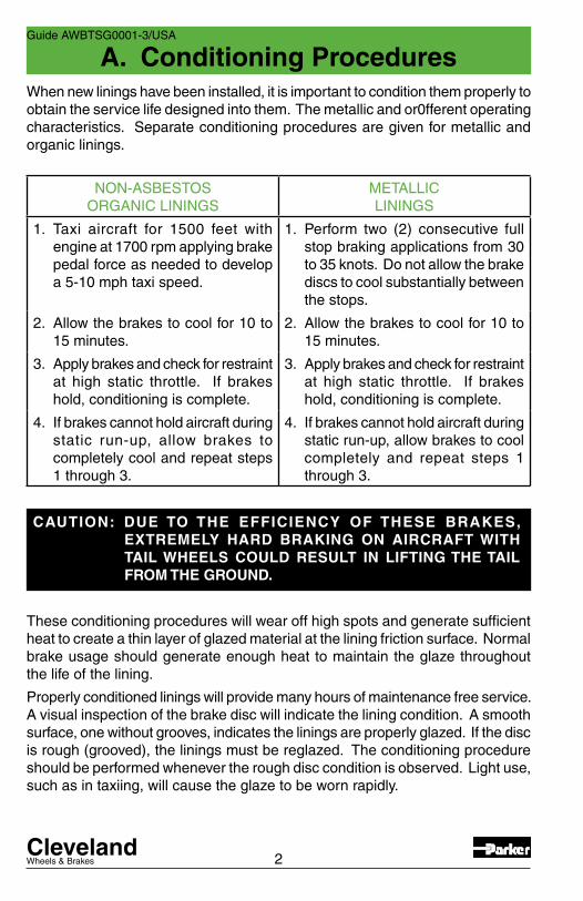
When new linings have been installed, it is important to condition them properly to obtain the service life designed into them. The metallic and or0fferent operating characteristics. Separate conditioning procedures are given for metallic and organic linings.
NON-ASBESTOSORGANIC LININGS
METALLICLININGS
1. Taxi aircraft for 1500 feet with engine at 1700 rpm applying brake pedal force as needed to develop a 5-10 mph taxi speed.
1. Perform two (2) consecutive full stop braking applications from 30 to 35 knots. Do not allow the brake discs to cool substantially between the stops.
2. Allow the brakes to cool for 10 to 15 minutes.
2. Allow the brakes to cool for 10 to 15 minutes.
3. Apply brakes and check for restraint at high static throttle. If brakes hold, conditioning is complete.
3. Apply brakes and check for restraint at high static throttle. If brakes hold, conditioning is complete.
4. If brakes cannot hold aircraft during static run-up, allow brakes to completely cool and repeat steps 1 through 3.
4. If brakes cannot hold aircraft during static run-up, allow brakes to cool completely and repeat steps 1 through 3.
CAUTION: DUE TO THE EFFICIENCY OF THESE BRAKES, EXTREMELY HARD BRAKING ON AIRCRAFT WITH TAIL WHEELS COULD RESULT IN LIFTING THE TAIL FROM THE GROUND.
These conditioning procedures will wear off high spots and generate sufficient heat to create a thin layer of glazed material at the lining friction surface. Normal brake usage should generate enough heat to maintain the glaze throughout the life of the lining.
Properly conditioned linings will provide many hours of maintenance free service. A visual inspection of the brake disc will indicate the lining condition. A smooth surface, one without grooves, indicates the linings are properly glazed. If the disc is rough (grooved), the linings must be reglazed. The conditioning procedure should be performed whenever the rough disc condition is observed. Light use, such as in taxiing, will cause the glaze to be worn rapidly.
A. Conditioning ProceduresGuide AWBTSG0001-3/USA
ClevelandWheels & Brakes 3
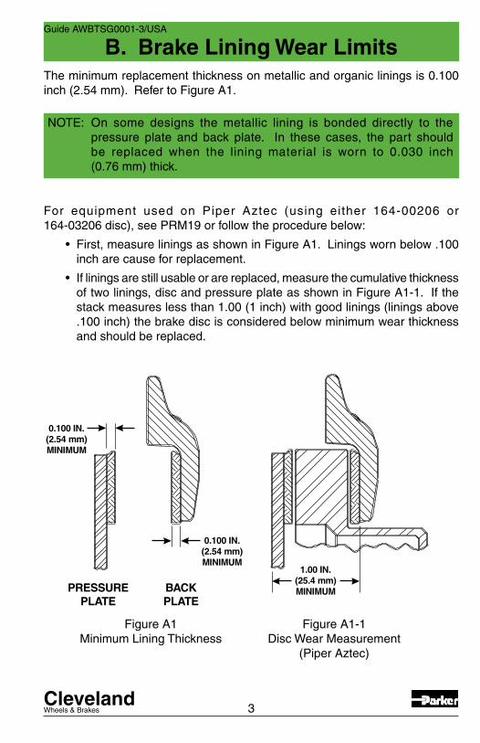
The minimum replacement thickness on metallic and organic linings is 0.100 inch (2.54 mm). Refer to Figure A1.
NOTE: On some designs the metallic lining is bonded directly to the pressure plate and back plate. In these cases, the part should be replaced when the lining material is worn to 0.030 inch (0.76 mm) thick.
For equipment used on Piper Aztec (using either 164-00206 or 164-03206 disc), see PRM19 or follow the procedure below:
• First,measureliningsasshowninFigureA1.Liningswornbelow.100inch are cause for replacement.
• Ifliningsarestillusableorarereplaced,measurethecumulativethicknessof two linings, disc and pressure plate as shown in Figure A1-1. If the stack measures less than 1.00 (1 inch) with good linings (linings above .100 inch) the brake disc is considered below minimum wear thickness and should be replaced.
PRESSUREPLATE
BACKPLATE
0.100 IN.(2.54 mm)MINIMUM
0.100 IN.(2.54 mm)MINIMUM
1.00 IN.(25.4 mm)MINIMUM
Figure A1 Minimum Lining Thickness
Figure A1-1 Disc Wear Measurement
(Piper Aztec)
B. Brake Lining Wear LimitsGuide AWBTSG0001-3/USA

ClevelandWheels & Brakes
C. Brake Disc Minimum Thickness
4
Guide AWBTSG0001-3/USA
Figure A2 – Disc Thickness Measurement
Under average field conditions, a brake disc should give years of trouble free service. However, unimproved fields, standing water, heavy industrial pollution or infrequent use of the aircraft may necessitate more frequent inspection of discs to prolong the life of the brake lining.
Generally, the disc faces should be checked for wear (Figure A2 Dim. “A”), grooves, deep scratches, excessive general pitting or coning of the brake disc. Coning beyond 0.015 inch (0.381 mm) in either direction would be cause for replacement.
Single or isolated grooves up to 0.030 inch (0.76 mm) deep should not be cause for replacement, although general grooving of the disc faces will reduce lining life.
Discs are plated for special applications only; therefore, rust in varying degrees can occur. If a powder rust appears, one or two braking applications during taxi should wipe the disc clear. Rust allowed to progress beyond this point may require removal of the disc from wheel assembly to properly clean both faces. Wire brushing followed by sanding with 220 grit sandpaper can restore the braking surface for continued use.
"A" MINIMUMTHICKNESS
ClevelandWheels & Brakes
C. Brake Disc Minimum Thickness
5
Guide AWBTSG0001-3/USA
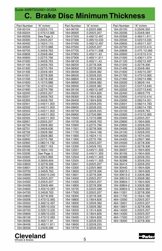
Part Number “A” in/mm164-06700 0.220/5.588164-06900 0.205/5.207164-07200 0.492/12.497164-07306 0.395/10.033164-07400 0.492/12.497164-07500 0.205/5.207164-07700 0.470/11.938164-07800 0.450/11.43164-07906 0.465/11.811164-08100 0.450/11.43164-08200 0.327/8.306164-08300 0.327/8.306164-08406 0.330/8.382164-08500 0.325/8.255164-08800 0.190/4.826164-08900 0.330/8.382164-09000 0.330/8.382164-09100 0.492/12.497164-09200 0.190/4.826164-09300 0.190/4.826164-09400 0.190/4.826164-09500 0.325/8.255164-09600 0.325/8.255164-09700 0.325/8.255164-09900 0.275/6.985164-10500 0.157/3.988164-10700 0.345/8.763164-10900 0.227/5.766164-11501 0.327/8.306164-11700 0.164/4.166164-11800 0.162/4.115164-11900 0.227/5.766164-12000 0.205/5.207164-12300 0.345/8.763164-12501 0.445/11.303164-12502 0.445/11.303164-12504 0.445/11.303164-12505 0.445/11.303164-12601 0.205/5.207164-13300 0.235/5.969164-13600 0.327/8.306164-13601 0.327/8.306164-14000 0.205/5.207164-14300 0.205/5.207164-14800 0.327/8.306164-16700 0.220/5.588164-17500 0.205/5.207164-18300 0.327/8.306164-18800 0.190/4.826164-18900 0.330/8.382164-19000 0.330/8.382164-19200 0.191/4.826164-19300 0.190/4.826164-19400 0.190/4.826164-19500 0.325/8.255164-19600 0.325/8.255164-19700 0.325/8.255
Part Number “A” in/mm164-20100 0.250/6.350164-20206 0.334/8.484164-20306 0.465/11.811164-20500 0.525/13.335164-20600 0.455/11.557164-20700 0.410/10.414164-20806 0.475 /12.065164-20900 0.410/10.414164-21000 0.436/11.074164-21100 0.492/12.497164-21200 0.327/8.306164-21406 0.334/8.484164-21600 0.405/10.287164-21700 0.475/12.065164-21900 0.590/14.986164-22000 0.360/9.144164-22201 0.537/13.640164-22202 0.537/13.640164-22400 0.385/9.779164-22900 0.410/10.414164-23000 0.565/14.351164-23001 0.582/14.783164-23002 0.582/14.783164-23100 0.345/8.763164-23300 0.475/12.065164-23400 0.205/5.207164-23600 0.190/4.826164-23900 0.325/8.255164-24000 0.325/8.255164-24100 0.325/8.255164-24200 0.167/4.242164-24400 0.290/7.366164-24500 0.327/8.306164-24501 0.327/8.306164-30007 0.190/4.826164-30195 0.190/4.826164-30388 0.325/8.255164-30398 0.325/8.255164-30414 0.325/8.255164-30440 0.190/4.826164-30615-1 0.190/4.826164-30615-2 0.330/8.382164-30615-3 0.330/8.382164-30804-1 0.190/4.826164-30804-2 0.330/8.382164-30804-3 0.330/8.382464-11501 0.327/8.306464-11700 0.164/4.166464-12000 0.205/5.207464-12601 0.205/5.207464-13601 0.327/8.306464-14000 0.205/5.207464-14300 0.205/5.207464-17500 0.205/5.207464-18300 0.327/8.306
Part Number “A” in/mm159-00104 0.225/5.715159-00204 0.475/12.065164-00206 See Page 3164-00300 0.205/5.207164-00400 0.162/4.115164-00500 0.157/3.988164-00700 0.345/8.763164-00806 0.334/8.484164-00900 0.227/5.766164-01000 0.345/8.763164-01100 0.345/8.763164-01300 0.227/5.764164-01406 0.334/8.484164-01501 0.327/8.306164-01506 0.327/8.306164-01600 0.157/3.988164-01700 0.167/4.242164-01900 0.227/5.766164-02000 0.205/5.207164-02201 0.345/8.763164-02300 0.345/8.763164-02501 0.445/11.303164-02502 0.445/11.303164-02503 0.445/11.303164-02504 0.445/11.303164-02505 0.445/11.303164-02601 0.205/5.207164-02700 0.330/8.382164-02701 0.340/8.636164-02706 0.330/8.382164-02707 0.330/8.382164-02800 0.227/5.766164-02900 0.580/14.732164-03006 0.282/7.163164-03106 0.163/4.140164-03206 See Page 3164-03300 0.235/5.969164-03506 0.260/6.604164-03600 0.327/8.306164-03601 0.327/8.306164-03700 0.345/8.763164-03906 0.600/15.240164-04000 0.205/5.207164-04300 0.205/5.207164-04406 0.334/8.484164-04600 0.405/10.287164-04700 0.345/8.763164-04800 0.327/8.306164-05006 0.475/12.065164-05500 0.492/12.497164-05606 0.395/10.033164-05700 0.525/13.335164-05806 0.395/10.033164-06106 0.475/12.065164-06306 0.465/11.81164-06406 0.465/11.811164-06506 0.240/6.096
ClevelandWheels & Brakes
D. Chrome/Performance Gold DiscMaintenance
E. Assembly/Lining Cross-Reference
6
Guide AWBTSG0001-3/USA
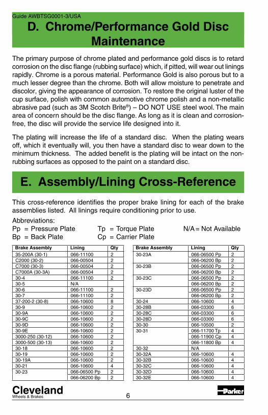
The primary purpose of chrome plated and performance gold discs is to retard corrosion on the disc flange (rubbing surface) which, if pitted, will wear out linings rapidly. Chrome is a porous material. Performance Gold is also porous but to a much lesser degree than the chrome. Both will allow moisture to penetrate and discolor, giving the appearance of corrosion. To restore the original luster of the cup surface, polish with common automotive chrome polish and a non-metallic abrasive pad (such as 3M Scotch Brite®) – DO NOT USE steel wool. The main area of concern should be the disc flange. As long as it is clean and corrosion-free, the disc will provide the service life designed into it.
The plating will increase the life of a standard disc. When the plating wears off, which it eventually will, you then have a standard disc to wear down to the minimum thickness. The added benefit is the plating will be intact on the non-rubbing surfaces as opposed to the paint on a standard disc.
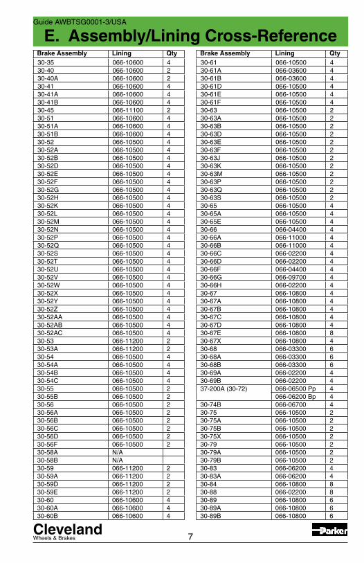
This cross-reference identifies the proper brake lining for each of the brake assemblies listed. All linings require conditioning prior to use.
Abbreviations:Pp = Pressure Plate Tp = Torque Plate N/A = Not AvailableBp = Back Plate Cp = Carrier Plate
Brake Assembly Lining Qty30-23A 066-06500 Pp 2
066-06200 Bp 230-23B 066-06500 Pp 2
066-06200 Bp 230-23C 066-06500 Pp 2
066-06200 Bp 230-23D 066-06500 Pp 2
066-06200 Bp 230-24 066-10600 430-28B 066-03300 630-28C 066-03300 630-28D 066-03300 630-30 066-10500 230-31 066-11700 Tp 4
066-11900 Cp 4066-11800 Bp 4
30-32 N/A30-32A 066-10600 430-32B 066-10600 430-32C 066-10600 430-32D 066-10600 430-32E 066-10600 4
Brake Assembly Lining Qty35-200A (30-1) 066-11100 2C2000 (30-2) 066-00504 2C7000 (30-3) 066-00504 2C7000A (30-3A) 066-00504 230-4 066-11100 230-5 N/A30-6 066-11100 230-7 066-11100 237-200-2 (30-8) 066-10600 830-9 066-10600 230-9A 066-10600 230-9C 066-10600 230-9D 066-10600 230-9E 066-10600 23000-250 (30-12) 066-10600 23000-500 (30-13) 066-10600 230-18 066-10600 230-19 066-10600 230-19A 066-10600 230-21 066-10600 430-23 066-06500 Pp 2
066-06200 Bp 2
ClevelandWheels & Brakes
E. Assembly/Lining Cross-Reference
7
Guide AWBTSG0001-3/USA
Brake Assembly Lining Qty30-35 066-10600 430-40 066-10600 230-40A 066-10600 230-41 066-10600 430-41A 066-10600 430-41B 066-10600 430-45 066-11100 230-51 066-10600 430-51A 066-10600 430-51B 066-10600 430-52 066-10500 430-52A 066-10500 430-52B 066-10500 430-52D 066-10500 430-52E 066-10500 430-52F 066-10500 430-52G 066-10500 430-52H 066-10500 430-52K 066-10500 430-52L 066-10500 430-52M 066-10500 430-52N 066-10500 430-52P 066-10500 430-52Q 066-10500 430-52S 066-10500 430-52T 066-10500 430-52U 066-10500 430-52V 066-10500 430-52W 066-10500 430-52X 066-10500 430-52Y 066-10500 430-52Z 066-10500 430-52AA 066-10500 430-52AB 066-10500 430-52AC 066-10500 430-53 066-11200 230-53A 066-11200 230-54 066-10500 430-54A 066-10500 430-54B 066-10500 430-54C 066-10500 430-55 066-10500 230-55B 066-10500 230-56 066-10500 230-56A 066-10500 230-56B 066-10500 230-56C 066-10500 230-56D 066-10500 230-56F 066-10500 230-58A N/A30-58B N/A30-59 066-11200 230-59A 066-11200 230-59D 066-11200 230-59E 066-11200 230-60 066-10600 430-60A 066-10600 430-60B 066-10600 4
Brake Assembly Lining Qty30-61 066-10500 430-61A 066-03600 430-61B 066-03600 430-61D 066-10500 430-61E 066-10500 430-61F 066-10500 430-63 066-10500 230-63A 066-10500 230-63B 066-10500 230-63D 066-10500 230-63E 066-10500 230-63F 066-10500 230-63J 066-10500 230-63K 066-10500 230-63M 066-10500 230-63P 066-10500 230-63Q 066-10500 230-63S 066-10500 230-65 066-10500 430-65A 066-10500 430-65E 066-10500 430-66 066-04400 430-66A 066-11000 430-66B 066-11000 430-66C 066-02200 430-66D 066-02200 430-66F 066-04400 430-66G 066-09700 430-66H 066-02200 430-67 066-10800 430-67A 066-10800 430-67B 066-10800 430-67C 066-10800 430-67D 066-10800 430-67E 066-10800 830-67X 066-10800 430-68 066-03300 630-68A 066-03300 630-68B 066-03300 630-69A 066-02200 430-69B 066-02200 437-200A (30-72) 066-06500 Pp 4
066-06200 Bp 430-74B 066-06700 430-75 066-10500 230-75A 066-10500 230-75B 066-10500 230-75X 066-10500 230-79 066-10500 230-79A 066-10500 230-79B 066-10500 230-83 066-06200 430-83A 066-06200 430-84 066-10800 830-88 066-02200 830-89 066-10800 630-89A 066-10800 630-89B 066-10800 6

ClevelandWheels & Brakes
E. Assembly/Lining Cross-Reference
8
Guide AWBTSG0001-3/USA
Brake Assembly Lining Qty30-89C 066-10800 630-89E 066-10800 630-91 066-11300 1230-93 066-04400 630-93A 066-02200 630-93B 066-04400 630-93C 066-09700 630-93D 066-04400 630-93E 066-04400 630-94 066-10800 830-95 066-03300 830-95A 066-06600 830-95B 066-06600 830-96 066-06200 830-97 066-06400 830-98 066-10800 1230-98A 066-10800 1230-98B 066-10800 1230-98C 066-10800 1230-98D 066-10800 1230-99 066-06600 830-99A 066-06600 830-100 066-06600 830-103 066-11300 1630-106 066-06800 1630-107 066-09000 830-107A 066-09000 830-107B 066-09000 830-107C 066-09000 830-107D 066-09000 830-107E 066-09000 830-111 066-10800 830-113 066-06400 830-113A 066-06400 830-123 066-06800 1230-127 066-06200 430-127A 066-06200 430-127C 066-06200 430-127D 066-06200 430-129 066-06200 430-131 066-09000 830-133 066-10500 230-138 066-06800 630-139 066-06200 830-141 066-07300 830-142 066-07300 830-143 066-07300 830-144 066-09000 830-144A 066-09000 830-144B 066-09000 830-145 066-09700 630-146 066-09100 Pp 2
066-09200 Bp 230-146A 066-09100 Pp 2
066-09200 Bp 230-148 066-11300 1630-149 066-06600 12
Brake Assembly Lining Qty30-158 066-06800 830-159 066-09000 830-159A 066-09000 830-159B 066-09000 830-159C 066-09000 830-163 066-03300 830-164 066-06200 230-170 066-10000 830-176 066-10800 430-181A 066-10600 230-182 066-03300 830-184 066-10800 830-195 066-10800 430-195A 066-10800 430-208 N/A30-208A 066-12901 230-210 066-13100 1630-210A 066-13100 1630-214 066-10500 230-214B 066-10500 230-220 066-13500 Pp 2
066-13700 Bp 230-224 066-10500 230-231 066-06600 1230-233 066-06200 430-233A 066-06200 430-233B 066-06200 430-236 066-10500 230-239 066-14100 230-239A 066-14100 230-239B 066-14100 230-241 066-10500 430-308 066-14800 2C-30018 066-30026 2C-30018-1 066-30026 2C-30018-2 066-30026 2C-30018-3 066-30026 2C-30018-4 066-30026 2C-30018-5 066-30026 2C-30018-6 066-30026 2C-30018-7 066-30026 2D-30118-3 066-30026 4D-30118-4 066-30026 4D-30118-5 066-30026 4D-30118-6 066-30026 4D-30118-7 066-30026 4D-30118-8 066-30026 4D-30118-9 066-30026 4D-30118-10 066-30026 4C-30764-5 066-30026 2C-30764-6 066-30026 2C-30764-7 066-30026 2D-30793-3 066-30026 4D-30793-4 066-30026 4D-30793-5 066-30026 4D-30793-6 066-30026 4

ClevelandWheels & Brakes
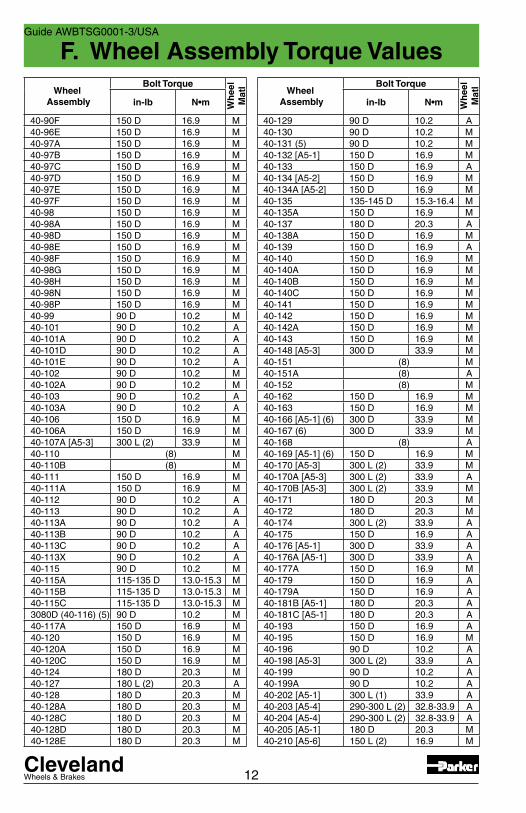
F. Wheel Assembly Torque Values
9
CAUTION: DO NOT “LUBTORK” ANY BOLT AND NUT COMBINATIONS THAT ARE SPECIFIED AS A “DRY” TORQUE VALUE. IF THERE IS ANY CONFLICT OR QUESTION REGARDING DRY TORQUE, LUBTORK OR TORQUE VALUE ON YOUR ASSEMBLY, PLEASE CONTACT CLEVELAND CUSTOMER SUPPORT FOR RESOLUTION.
Guide AWBTSG0001-3/USA
CAUTION: DO NOT MIX AVIATION WHEEL BEARING GREASES WITH EACH OTHER. IF USING OTHER APPROVED GREASE, COMPLETE REMOVAL OF CONTAINED GREASE AND BEARING CLEANING IS REQUIRED. REPLACEMENT OF PREVIOUSLY LUBRICATED FELT SEALS IS ALSO REQUIRED.
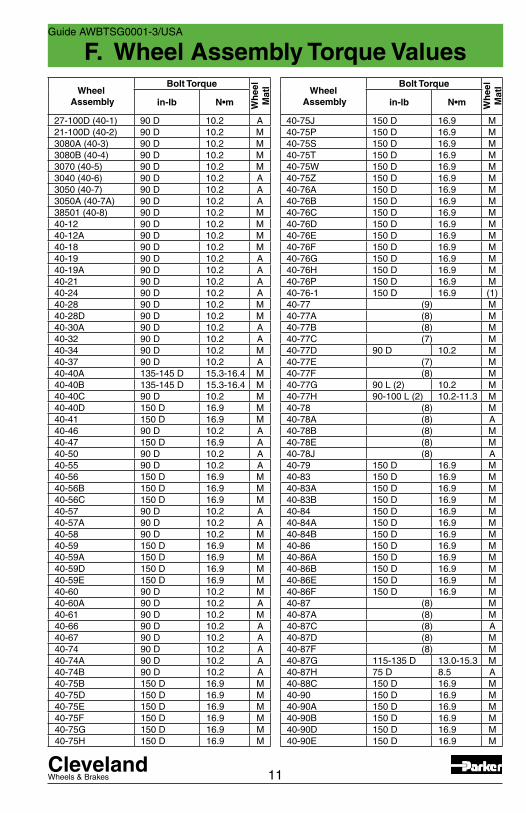
All wheel assembly tie bolt and nut torque values listed are to be applied to the nut only. A “D” shown adjacent to the torque value indicates the value to be a “Dry” torque only. An “L” shown adjacent to the torque value indicates a “Lubtork” torque only. Lubtork requires the application of an antiseize compound to all friction surfaces of the hardware prior to torquing. Only use the antiseize specified for your wheel assembly.
[A5-#] = Code for inflation valve stem torque. See appropriate dash number,-#, in Table G for torque value.
Included in this section is wheel bearing grease information. Beginning March, 2007 all active wheel assemblies listed in the torque values table, except those noted for amphibious application, will be shipped from the Cleveland Wheels & Brakes facility with the bearings packed with Mobil Aviation Grease SHC 100, the approved preferred grease for all Parker Hannifin wheel assemblies.
If your non-amphibious wheel assembly was shipped prior to March 2007 it may contain other approved bearing grease. To change to the Mobil Aviation Grease SHC 100, you must completely remove the contained grease and clean the bearings. You must also replace any felt grease seals which were previously lubricated with other approved grease.
Refer to Cleveland Wheels & Brakes Component Maintenance Manual, AWBCMM0001, latest issue for additional information and grease packing instructions.
Torque Values
Bearing Grease
ClevelandWheels & Brakes
F. Wheel Assembly Torque Values
10
Guide AWBTSG0001-3/USA
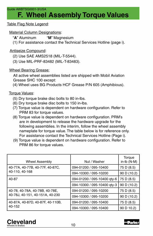
Table Flag Note Legend:
Material Column Designations: “A” Aluminum “M” Magnesium (1) For assistance contact the Technical Services Hotline (page i).
Antiseize Compound: (2) Use SAE AMS2518 (MIL-T-5544). (3) Use MIL-PRF-83482 (MIL-T-83483).
Wheel Bearing Grease: All active wheel assemblies listed are shipped with Mobil Aviation Grease SHC 100 except: (4) Wheel uses BG Products HCF Grease P/N 605 (Amphibious).
Torque Values: (5) Dry torque brake disc bolts to 80 in-lbs. (6) Dry torque brake disc bolts to 150 in-lbs. (7) Torque value is dependent on hardware configuration. Refer to PRM 83 for torque values. (8) Torque value is dependent on hardware configuration. PRM’s are in development to release the hardware upgrade for the following assemblies. In the interim, follow the wheel assembly nameplate for torque value. The table below is for reference only. For assistance contact the Technical Services Hotline (Page i). (9) Torque value is dependent on hardware configuration. Refer to PRM 86 for torque values.
Wheel Assembly Nut / WasherTorque
in-lb (N-M)
40-77A, 40-77B, 40-77F, 40-87C, 40-110, 40-168
094-01200 / 095-10400 75 D (8.5)
094-10300 / 095-10200 90 D (10.2)
40-87 094-01200 / 095-10400 qty-6 75 D (8.5)
094-10300 / 095-10400 qty-3 90 D (10.2)
40-78, 40-78A, 40-78B, 40-78E,40-78J, 40-151, 40-151A, 40-230
094-01200 / 095-10200 75 D (8.5)
094-10300 / 095-10200 90 D (10.2)
40-87A, 40-87D, 40-87F, 40-110B, 40-152
094-01200 / 095-10400 75 D (8.5)
094-10300 / 095-10400 90 D 10.2)
ClevelandWheels & Brakes
F. Wheel Assembly Torque Values
11
Guide AWBTSG0001-3/USA
Wheel Assembly
Bolt Torque
Wh
eel
Mat
l
in-lb N•m
27-100D (40-1) 90 D 10.2 A21-100D (40-2) 90 D 10.2 M3080A (40-3) 90 D 10.2 M3080B (40-4) 90 D 10.2 M3070 (40-5) 90 D 10.2 M3040 (40-6) 90 D 10.2 A3050 (40-7) 90 D 10.2 A3050A (40-7A) 90 D 10.2 A38501 (40-8) 90 D 10.2 M40-12 90 D 10.2 M40-12A 90 D 10.2 M40-18 90 D 10.2 M40-19 90 D 10.2 A40-19A 90 D 10.2 A40-21 90 D 10.2 A40-24 90 D 10.2 A40-28 90 D 10.2 M40-28D 90 D 10.2 M40-30A 90 D 10.2 A40-32 90 D 10.2 A40-34 90 D 10.2 M40-37 90 D 10.2 A40-40A 135-145 D 15.3-16.4 M40-40B 135-145 D 15.3-16.4 M40-40C 90 D 10.2 M40-40D 150 D 16.9 M40-41 150 D 16.9 M40-46 90 D 10.2 A40-47 150 D 16.9 A40-50 90 D 10.2 A40-55 90 D 10.2 A40-56 150 D 16.9 M40-56B 150 D 16.9 M40-56C 150 D 16.9 M40-57 90 D 10.2 A40-57A 90 D 10.2 A40-58 90 D 10.2 M40-59 150 D 16.9 M40-59A 150 D 16.9 M40-59D 150 D 16.9 M40-59E 150 D 16.9 M40-60 90 D 10.2 M40-60A 90 D 10.2 A40-61 90 D 10.2 M40-66 90 D 10.2 A40-67 90 D 10.2 A40-74 90 D 10.2 A40-74A 90 D 10.2 A40-74B 90 D 10.2 A40-75B 150 D 16.9 M40-75D 150 D 16.9 M40-75E 150 D 16.9 M40-75F 150 D 16.9 M40-75G 150 D 16.9 M40-75H 150 D 16.9 M
Wheel Assembly
Bolt Torque
Wh
eel
Mat
l
in-lb N•m
40-75J 150 D 16.9 M40-75P 150 D 16.9 M40-75S 150 D 16.9 M40-75T 150 D 16.9 M40-75W 150 D 16.9 M40-75Z 150 D 16.9 M40-76A 150 D 16.9 M40-76B 150 D 16.9 M40-76C 150 D 16.9 M40-76D 150 D 16.9 M40-76E 150 D 16.9 M40-76F 150 D 16.9 M40-76G 150 D 16.9 M40-76H 150 D 16.9 M40-76P 150 D 16.9 M40-76-1 150 D 16.9 (1)40-77 (9) M40-77A (8) M40-77B (8) M40-77C (7) M40-77D 90 D 10.2 M40-77E (7) M40-77F (8) M40-77G 90 L (2) 10.2 M40-77H 90-100 L (2) 10.2-11.3 M40-78 (8) M40-78A (8) A40-78B (8) M40-78E (8) M40-78J (8) A40-79 150 D 16.9 M40-83 150 D 16.9 M40-83A 150 D 16.9 M40-83B 150 D 16.9 M40-84 150 D 16.9 M40-84A 150 D 16.9 M40-84B 150 D 16.9 M40-86 150 D 16.9 M40-86A 150 D 16.9 M40-86B 150 D 16.9 M40-86E 150 D 16.9 M40-86F 150 D 16.9 M40-87 (8) M40-87A (8) M40-87C (8) A40-87D (8) M40-87F (8) M40-87G 115-135 D 13.0-15.3 M40-87H 75 D 8.5 A40-88C 150 D 16.9 M40-90 150 D 16.9 M40-90A 150 D 16.9 M40-90B 150 D 16.9 M40-90D 150 D 16.9 M40-90E 150 D 16.9 M
ClevelandWheels & Brakes
F. Wheel Assembly Torque Values
12
Guide AWBTSG0001-3/USA
Wheel Assembly
Bolt Torque
Wh
eel
Mat
l
in-lb N•m
40-129 90 D 10.2 A40-130 90 D 10.2 M40-131 (5) 90 D 10.2 M40-132 [A5-1] 150 D 16.9 M40-133 150 D 16.9 A40-134 [A5-2] 150 D 16.9 M40-134A [A5-2] 150 D 16.9 M40-135 135-145 D 15.3-16.4 M40-135A 150 D 16.9 M40-137 180 D 20.3 A40-138A 150 D 16.9 M40-139 150 D 16.9 A40-140 150 D 16.9 M40-140A 150 D 16.9 M40-140B 150 D 16.9 M40-140C 150 D 16.9 M40-141 150 D 16.9 M40-142 150 D 16.9 M40-142A 150 D 16.9 M40-143 150 D 16.9 M40-148 [A5-3] 300 D 33.9 M40-151 (8) M40-151A (8) A40-152 (8) M40-162 150 D 16.9 M40-163 150 D 16.9 M40-166 [A5-1] (6) 300 D 33.9 M40-167 (6) 300 D 33.9 M40-168 (8) A40-169 [A5-1] (6) 150 D 16.9 M40-170 [A5-3] 300 L (2) 33.9 M40-170A [A5-3] 300 L (2) 33.9 A40-170B [A5-3] 300 L (2) 33.9 M40-171 180 D 20.3 M40-172 180 D 20.3 M40-174 300 L (2) 33.9 A40-175 150 D 16.9 A40-176 [A5-1] 300 D 33.9 A40-176A [A5-1] 300 D 33.9 A40-177A 150 D 16.9 M40-179 150 D 16.9 A40-179A 150 D 16.9 A40-181B [A5-1] 180 D 20.3 A40-181C [A5-1] 180 D 20.3 A40-193 150 D 16.9 A40-195 150 D 16.9 M40-196 90 D 10.2 A40-198 [A5-3] 300 L (2) 33.9 A40-199 90 D 10.2 A40-199A 90 D 10.2 A40-202 [A5-1] 300 L (1) 33.9 A40-203 [A5-4] 290-300 L (2) 32.8-33.9 A40-204 [A5-4] 290-300 L (2) 32.8-33.9 A40-205 [A5-1] 180 D 20.3 M40-210 [A5-6] 150 L (2) 16.9 M
Wheel Assembly
Bolt Torque
Wh
eel
Mat
l
in-lb N•m
40-90F 150 D 16.9 M40-96E 150 D 16.9 M40-97A 150 D 16.9 M40-97B 150 D 16.9 M40-97C 150 D 16.9 M40-97D 150 D 16.9 M40-97E 150 D 16.9 M40-97F 150 D 16.9 M40-98 150 D 16.9 M40-98A 150 D 16.9 M40-98D 150 D 16.9 M40-98E 150 D 16.9 M40-98F 150 D 16.9 M40-98G 150 D 16.9 M40-98H 150 D 16.9 M40-98N 150 D 16.9 M40-98P 150 D 16.9 M40-99 90 D 10.2 M40-101 90 D 10.2 A40-101A 90 D 10.2 A40-101D 90 D 10.2 A40-101E 90 D 10.2 A40-102 90 D 10.2 M40-102A 90 D 10.2 M40-103 90 D 10.2 A40-103A 90 D 10.2 A40-106 150 D 16.9 M40-106A 150 D 16.9 M40-107A [A5-3] 300 L (2) 33.9 M40-110 (8) M40-110B (8) M40-111 150 D 16.9 M40-111A 150 D 16.9 M40-112 90 D 10.2 A40-113 90 D 10.2 A40-113A 90 D 10.2 A40-113B 90 D 10.2 A40-113C 90 D 10.2 A40-113X 90 D 10.2 A40-115 90 D 10.2 M40-115A 115-135 D 13.0-15.3 M40-115B 115-135 D 13.0-15.3 M40-115C 115-135 D 13.0-15.3 M3080D (40-116) (5) 90 D 10.2 M40-117A 150 D 16.9 M40-120 150 D 16.9 M40-120A 150 D 16.9 M40-120C 150 D 16.9 M40-124 180 D 20.3 M40-127 180 L (2) 20.3 A40-128 180 D 20.3 M40-128A 180 D 20.3 M40-128C 180 D 20.3 M40-128D 180 D 20.3 M40-128E 180 D 20.3 M
ClevelandWheels & Brakes
F. Wheel Assembly Torque Values
13
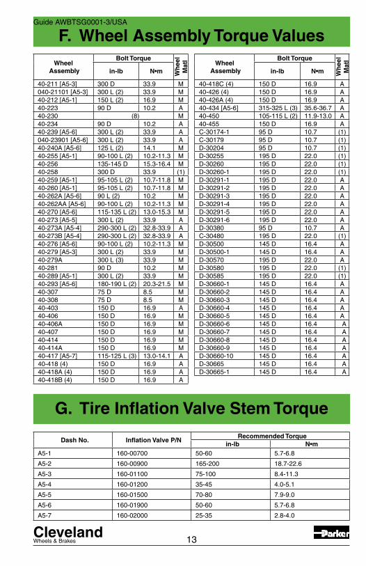
G. Tire Inflation Valve Stem Torque
Guide AWBTSG0001-3/USA
Wheel Assembly
Bolt Torque
Wh
eel
Mat
l
in-lb N•m
40-211 [A5-3] 300 D 33.9 M040-21101 [A5-3] 300 L (2) 33.9 M40-212 [A5-1] 150 L (2) 16.9 M40-223 90 D 10.2 A40-230 (8) M40-234 90 D 10.2 A40-239 [A5-6] 300 L (2) 33.9 A040-23901 [A5-6] 300 L (2) 33.9 A40-240A [A5-6] 125 L (2) 14.1 M40-255 [A5-1] 90-100 L (2) 10.2-11.3 M40-256 135-145 D 15.3-16.4 M40-258 300 D 33.9 (1)40-259 [A5-1] 95-105 L (2) 10.7-11.8 M40-260 [A5-1] 95-105 L (2) 10.7-11.8 M40-262A [A5-6] 90 L (2) 10.2 M40-262AA [A5-6] 90-100 L (2) 10.2-11.3 M40-270 [A5-6] 115-135 L (2) 13.0-15.3 M40-273 [A5-5] 300 L (2) 33.9 A40-273A [A5-4] 290-300 L (2) 32.8-33.9 A40-273B [A5-4] 290-300 L (2) 32.8-33.9 A40-276 [A5-6] 90-100 L (2) 10.2-11.3 M40-279 [A5-3] 300 L (2) 33.9 M40-279A 300 L (3) 33.9 M40-281 90 D 10.2 M40-289 [A5-1] 300 L (2) 33.9 M40-293 [A5-6] 180-190 L (2) 20.3-21.5 M40-307 75 D 8.5 M40-308 75 D 8.5 M40-403 150 D 16.9 A40-406 150 D 16.9 M40-406A 150 D 16.9 M40-407 150 D 16.9 M40-414 150 D 16.9 M40-414A 150 D 16.9 M40-417 [A5-7] 115-125 L (3) 13.0-14.1 A40-418 (4) 150 D 16.9 A40-418A (4) 150 D 16.9 A40-418B (4) 150 D 16.9 A
Dash No. Inflation Valve P/NRecommended Torque
in-lb N•mA5-1 160-00700 50-60 5.7-6.8
A5-2 160-00900 165-200 18.7-22.6
A5-3 160-01100 75-100 8.4-11.3
A5-4 160-01200 35-45 4.0-5.1
A5-5 160-01500 70-80 7.9-9.0
A5-6 160-01900 50-60 5.7-6.8
A5-7 160-02000 25-35 2.8-4.0
Wheel Assembly
Bolt Torque
Wh
eel
Mat
l
in-lb N•m
40-418C (4) 150 D 16.9 A40-426 (4) 150 D 16.9 A40-426A (4) 150 D 16.9 A40-434 [A5-6] 315-325 L (3) 35.6-36.7 A40-450 105-115 L (2) 11.9-13.0 A40-455 150 D 16.9 AC-30174-1 95 D 10.7 (1)C-30179 95 D 10.7 (1)D-30204 95 D 10.7 (1)D-30255 195 D 22.0 (1)D-30260 195 D 22.0 (1)D-30260-1 195 D 22.0 (1)D-30291-1 195 D 22.0 AD-30291-2 195 D 22.0 AD-30291-3 195 D 22.0 AD-30291-4 195 D 22.0 AD-30291-5 195 D 22.0 AD-30291-6 195 D 22.0 AD-30380 95 D 10.7 AC-30480 195 D 22.0 (1)D-30500 145 D 16.4 AD-30500-1 145 D 16.4 AD-30570 195 D 22.0 AD-30580 195 D 22.0 (1)D-30585 195 D 22.0 (1)D-30660-1 145 D 16.4 AD-30660-2 145 D 16.4 AD-30660-3 145 D 16.4 AD-30660-4 145 D 16.4 AD-30660-5 145 D 16.4 AD-30660-6 145 D 16.4 AD-30660-7 145 D 16.4 AD-30660-8 145 D 16.4 AD-30660-9 145 D 16.4 AD-30660-10 145 D 16.4 AD-30665 145 D 16.4 AD-30665-1 145 D 16.4 A
ClevelandWheels & Brakes
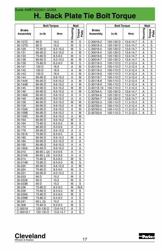
H. Back Plate Tie Bolt Torque
14
Guide AWBTSG0001-3/USA
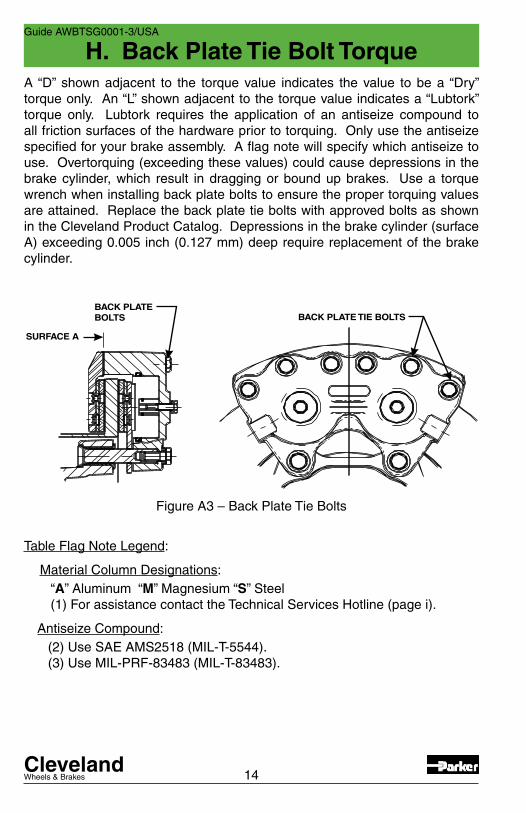
A “D” shown adjacent to the torque value indicates the value to be a “Dry” torque only. An “L” shown adjacent to the torque value indicates a “Lubtork” torque only. Lubtork requires the application of an antiseize compound to all friction surfaces of the hardware prior to torquing. Only use the antiseize specified for your brake assembly. A flag note will specify which antiseize to use. Overtorquing (exceeding these values) could cause depressions in the brake cylinder, which result in dragging or bound up brakes. Use a torque wrench when installing back plate bolts to ensure the proper torquing values are attained. Replace the back plate tie bolts with approved bolts as shown in the Cleveland Product Catalog. Depressions in the brake cylinder (surface A) exceeding 0.005 inch (0.127 mm) deep require replacement of the brake cylinder.
BACK PLATE TIE BOLTSBACK PLATEBOLTS
SURFACE A
Figure A3 – Back Plate Tie Bolts
Table Flag Note Legend:
Material Column Designations: “A” Aluminum “M” Magnesium “S” Steel (1) For assistance contact the Technical Services Hotline (page i).
Antiseize Compound: (2) Use SAE AMS2518 (MIL-T-5544). (3) Use MIL-PRF-83483 (MIL-T-83483).

ClevelandWheels & Brakes
H. Back Plate Tie Bolt Torque
15
Guide AWBTSG0001-3/USA
BrakeAssembly
Bolt Torque Matl
in-lb N•m
Ho
usi
ng
Torq
ue
Pla
te
35-200A(30-1)
60 D 6.8 A S
30-4 60 D 6.8 A S30-5 60 D 6.8 A S30-6 60 D 6.8 A S30-7 60 D 6.8 A S30-4 60 D 6.8 A S37-200-2(30-8)
90 D 10.2 A S
30-9 75-80 D 8.5-9.0 A S30-9A 75-80 D 8.5-9.0 A S30-9C 75-80 D 8.5-9.0 A S30-9D 75-80 D 8.5-9.0 A S30-9E 75-80 D 8.5-9.0 A S3000-250(30-12)
90 D 10.2 A S
3000-500(30-13)
90 D 10.2 A S
30-18 75-80 D 8.5-9.0 A S30-19 75-80 D 8.5-9.0 A S30-19A 75-80 D 8.5-9.0 A S30-21 65-75 D 7.3-8.5 A S30-23 65-75 D 7.3-8.5 A N/A30-23A 65-75 D 7.3-8.5 A N/A30-23B 65-75 D 7.3-8.5 A N/A30-23C 65-75 D 7.3-8.5 A N/A30-23D 65-75 D 7.3-8.5 A N/A30-24 65-75 D 7.3-8.5 (1) (1)30-28B 80-90 D 9.0-10.2 M M30-28C 80-90 D 9.0-10.2 M M30-28D 80-90 D 9.0-10.2 M M30-30 90 D 10.2 M S
30-31
1/4-2885-90 D
9.6-10.2A S
3/8-24125-150 D
14.0-17.0
30-32 65-75 D 7.3-8.5 A S30-32A 65-75 D 7.3-8.5 A S30-32B 65-75 D 7.3-8.5 A S30-32C 65-75 D 7.3-8.5 A S30-32E 65-75 D 7.3-8.5 A S30-35 65-75 D 7.3-8.5 (1) S30-40 60 D 6.8 A S30-40A 75-80 D 8.5-9.0 A S30-41 65-75 D 7.3-8.5 A N/A30-41A 90 D 10.2 A S30-41B 65-75 D 7.3-8.5 A N/A30-45 60 D 6.8 A S
BrakeAssembly
Bolt Torque Matl
in-lb N•m
Ho
usi
ng
Torq
ue
Pla
te
30-51 65-75 D 7.3-8.5 A S30-51A 65-75 D 7.3-8.5 A S30-51B 65-75 D 7.3-8.5 A S30-52 90 D 10.2 M S30-52A 90 D 10.2 M S30-52B 90 D 10.2 M S30-52D 90 D 10.2 M S30-52E 90 D 10.2 M S30-52F 90 D 10.2 M S30-52G 90 D 10.2 M S30-52H 90 D 10.2 M S30-52K 90 D 10.2 M S30-52L 75-80 D 8.5-9.0 M N/A30-52M 90 D 10.2 M S30-52N 90 D 10.2 M S30-52P 90 D 10.2 M S30-52Q 90 D 10.2 M S30-52S 90 D 10.2 M S30-52T 90 D 10.2 M S30-52U 90 D 10.2 M S30-52V 90 D 10.2 M S30-52W 90 D 10.2 M S30-52X 90 D 10.2 M S30-52Y 90 D 10.2 M S30-52Z 90 D 10.2 M S30-52AA 90 D 10.2 M S30-52AB 90 D 10.2 M S30-52AC 90 D 10.2 M S30-53 75-80 D 8.5-9.0 (1) (1)30-53A 75-80 D 8.5-9.0 M S30-54 90 D 10.2 M A30-54A 90 D 10.2 M A30-54B 90 D 10.2 M S30-54C 85-90 D 9.6-10.2 M A30-55 75-80 D 8.5-9.0 M S30-55A 75-80 D 8.5-9.0 (1) (1)30-55B 75-80 D 8.5-9.0 M S30-56 75-80 D 8.5-9.0 M S30-56A 75-80 D 8.5-9.0 M S30-56B 75-80 D 8.5-9.0 M S30-56C 75-80 D 8.5-9.0 M S30-56D 75-80 D 8.5-9.0 M S30-56F 75-80 D 8.5-9.0 M S30-58A 75-80 D 8.5-9.0 (1) (1)30-58B 75-80 D 8.5-9.0 M (1)30-59 75-80 D 8.5-9.0 M S30-59A 75-80 D 8.5-9.0 M S30-59E 75-80 D 8.5-9.0 M S
ClevelandWheels & Brakes
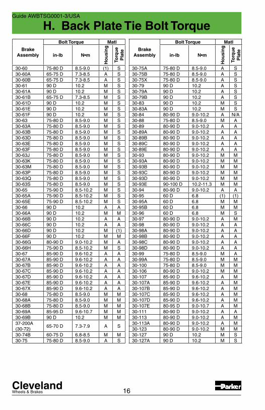
H. Back Plate Tie Bolt Torque
16
Guide AWBTSG0001-3/USA
BrakeAssembly
Bolt Torque Matl
in-lb N•m
Ho
usi
ng
Torq
ue
Pla
te
30-75A 75-80 D 8.5-9.0 A S30-75B 75-80 D 8.5-9.0 A S30-75X 75-80 D 8.5-9.0 A S30-79 90 D 10.2 A S30-79A 90 D 10.2 A S30-79B 90 D 10.2 A S30-83 90 D 10.2 M S30-83A 90 D 10.2 M S30-84 80-90 D 9.0-10.2 A N/A30-88 75-80 D 8.5-9.0 M A30-89 80-90 D 9.0-10.2 A A30-89A 80-90 D 9.0-10.2 A A30-89B 80-90 D 9.0-10.2 A A30-89C 80-90 D 9.0-10.2 A A30-89E 80-90 D 9.0-10.2 A A30-93 80-90 D 9.0-10.2 M M30-93A 80-90 D 9.0-10.2 M M30-93B 80-90 D 9.0-10.2 M M30-93C 80-90 D 9.0-10.2 M M30-93D 80-90 D 9.0-10.2 M M30-93E 90-100 D 10.2-11.3 M M30-94 80-90 D 9.0-10.2 A A30-95 60 D 6.8 (1) (1)30-95A 60 D 6.8 M M30-95B 60 D 6.8 M M30-96 60 D 6.8 M S30-97 80-90 D 9.0-10.2 A M30-98 80-90 D 9.0-10.2 A A30-98A 80-90 D 9.0-10.2 A A30-98B 80-90 D 9.0-10.2 A A30-98C 80-90 D 9.0-10.2 A A30-98D 80-90 D 9.0-10.2 A A30-99 75-80 D 8.5-9.0 M A30-99A 75-80 D 8.5-9.0 M M30-100 75-80 D 8.5-9.0 M M30-106 80-90 D 9.0-10.2 M M30-107 85-90 D 9.6-10.2 A M30-107A 85-90 D 9.6-10.2 A M30-107B 85-90 D 9.6-10.2 A M30-107C 85-90 D 9.6-10.2 A M30-107D 85-90 D 9.6-10.2 A M30-107E 80-95 D 9.0-10.7 A M30-111 80-90 D 9.0-10.2 A A30-113 80-90 D 9.0-10.2 A M30-113A 80-90 D 9.0-10.2 A M30-123 80-90 D 9.0-10.2 M M30-127 90 D 10.2 M S30-127A 90 D 10.2 M S
BrakeAssembly
Bolt Torque Matl
in-lb N•m
Ho
usi
ng
Torq
ue
Pla
te
30-60 75-80 D 8.5-9.0 (1) S30-60A 65-75 D 7.3-8.5 A S30-60B 65-75 D 7.3-8.5 A S30-61 90 D 10.2 M S30-61A 90 D 10.2 M S30-61B 65-75 D 7.3-8.5 M S30-61D 90 D 10.2 M S30-61E 90 D 10.2 M S30-61F 90 D 10.2 M S30-63 75-80 D 8.5-9.0 M S30-63A 75-80 D 8.5-9.0 M S30-63B 75-80 D 8.5-9.0 M S30-63D 75-80 D 8.5-9.0 M S30-63E 75-80 D 8.5-9.0 M S30-63F 75-80 D 8.5-9.0 M S30-63J 75-80 D 8.5-9.0 M S30-63K 75-80 D 8.5-9.0 M S30-63M 75-80 D 8.5-9.0 M S30-63P 75-80 D 8.5-9.0 M S30-63Q 75-80 D 8.5-9.0 M S30-63S 75-80 D 8.5-9.0 M S30-65 75-90 D 8.5-10.2 M S30-65A 75-90 D 8.5-10.2 M S30-65E 75-90 D 8.5-10.2 M S30-66 90 D 10.2 A A30-66A 90 D 10.2 M M30-66B 90 D 10.2 A A30-66C 90 D 10.2 A A30-66D 90 D 10.2 M (1)30-66F 90 D 10.2 M M30-66G 80-90 D 9.0-10.2 M A30-66H 75-90 D 8.5-10.2 M S30-67 85-90 D 9.6-10.2 A A30-67A 85-90 D 9.6-10.2 A A30-67B 85-90 D 9.6-10.2 A A30-67C 85-90 D 9.6-10.2 A A30-67D 85-90 D 9.6-10.2 A A30-67E 85-90 D 9.6-10.2 A A30-67X 85-90 D 9.6-10.2 A A30-68 75-80 D 8.5-9.0 M M30-68A 75-80 D 8.5-9.0 M M30-68B 75-80 D 8.5-9.0 M M30-69A 85-95 D 9.6-10.7 M M30-69B 90 D 10.2 M M37-200A(30-72)
65-70 D 7.3-7.9 A S
30-74B 60-75 D 6.8-8.5 M M30-75 75-80 D 8.5-9.0 A S
ClevelandWheels & Brakes
H. Back Plate Tie Bolt Torque
17
Guide AWBTSG0001-3/USA
BrakeAssembly
Bolt Torque Matl
in-lb N•m
Ho
usi
ng
Torq
ue
Pla
te
30-127C 90 D 10.2 M S30-127D 90 D 10.2 M S30-129 75-90 D 8.5-10.2 M S30-131 80-90 D 9.0-10.2 A M30-133 75-80 D 8.5-9.0 M S30-138 80-90 D 9.0-10.2 M M30-139 75-80 D 8.5-9.0 M S30-141 150 D 16.9 A M30-142 150 D 16.9 A M30-143 150 D 16.9 A M30-144 85-90 D 9.6-10.2 A M30-144A 85-90 D 9.6-10.2 A M30-144B 85-90 D 9.6-10.2 A M30-145 80-90 D 9.0-10.2 M M30-146 85-90 D 9.6-10.2 A M30-146A 85-90 D 9.6-10.2 A A30-149 80-90 D 9.0-10.2 A A30-158 80-90 D 9.0-10.2 M M30-159 85-90 D 9.6-10.2 A M30-159A 85-90 D 9.6-10.2 A M30-159B 85-90 D 9.6-10.2 A M30-159C 85-90 D 9.6-10.2 A M30-163 85-90 D 9.6-10.2 M A30-164 75-80 D 8.5-9.0 M S30-170 80-85 D 9.0-9.6 A A30-176 85-90 D 9.6-10.2 A A30-181A 75-80 D 8.5-9.0 A S30-182 85-90 D 9.6-10.2 M A30-184 80-90 D 9.0-10.2 A A30-195 85-90 D 9.6-10.2 A A30-195A 85-90 D 9.6-10.2 A A30-210 80-85 L (2) 9.0-9.6 A A30-210A 80-85 L (3) 9.0-9.6 A A30-214 75-80 D 8.5-9.0 M S30-214B 75-80 D 8.5-9.0 M S30-220 85-90 D 9.6-10.2 A M30-224 75-80 D 8.5-9.0 M S30-231 80-90 D 9.0-10.2 A A30-233 90 D 10.2 M S30-233A 90 D 10.2 M S30-233B 90 D 10.2 M S30-236 75-80 D 8.5-9.0 M N/A30-239 75-80 D 8.5-9.0 M S30-239A 75-80 D 8.5-9.0 M S30-239B 75-80 D 8.5-9.0 A S30-241 90 L (3) 10.2 A S30-308 75-80 D 8.5-9.0 M SC-30018 120-130 D 13.6-14.7 A SC-30018-1 120-130 D 13.6-14.7 A S
BrakeAssembly
Bolt Torque Matl
in-lb N•m
Ho
usi
ng
Torq
ue
Pla
te
C-30018-2 120-130 D 13.6-14.7 A SC-30018-3 120-130 D 13.6-14.7 A SC-30018-4 120-130 D 13.6-14.7 A SC-30018-5 120-130 D 13.6-14.7 A SC-30018-6 120-130 D 13.6-14.7 A SC-30018-7 120-130 D 13.6-14.7 A SD-30118-3 100-110 D 11.3-12.4 A SD-30118-4 100-110 D 11.3-12.4 A SD-30118-5 100-110 D 11.3-12.4 A SD-30118-6 100-110 D 11.3-12.4 A SD-30118-7 100-110 D 11.3-12.4 A SD-30118-8 100-110 D 11.3-12.4 A SD-30118-9 100-110 D 11.3-12.4 A SD-30118-10 100-110 D 11.3-12.4 A SC-30764-5 120-130 D 13.6-14.7 A SC-30764-6 120-130 D 13.6-14.7 A SC-30764-7 120-130 D 13.6-14.7 A SD-30793-3 100-110 D 11.3-12.4 A SD-30793-4 100-110 D 11.3-12.4 A SD-30793-5 100-110 D 11.3-12.4 A SD-30793-6 100-110 D 11.3-12.4 A S

ClevelandWheels & Brakes 18
I. Special Tools
J. Elastomeric Compound Lubricants
K. Lubricants
Guide AWBTSG0001-3/USA
Wheel Bearing Grease – Refer to Topic F, Bearing Grease paragraph MIL-PRF-81322, Grade 2 or DOD-G-24508A (Aeroshell Grease 22) Shell Oil Company, Metairie, LA Mobil Aviation Grease SHC 100 ExxonMobil Oil Corp., Beaumont, TX HCF Grease P/N 605 (Amphibious) BG Products, Wichita, KS
Bolts/Nuts Antiseize – Use antiseize specified for your assembly per SAE-AMS2518 (MIL-T-5544) Armite Laboratories, Costa Mesa, CA Royco 44 - Royal Lubricant, East Hanover, NJ per MIL-PRF-83483
Moly-50 P/N 51094 – Fel-Pro Chemical Products L.P., Skokie, IL
Pipe Threads - Apply to first 3 threads of brake cylinder inlet fittings Lubon #404 – Oil Center Research, Lafayette, LA
Pneumatic Applications Grease per MIL-G-4343 Royco 43 – Royal Lubricants Co., East Hanover, NJ Aeroshell 43 – Royal Lubricants Co., Inc., East Hanover, NJ Cosmolube 615 – Houghton International, Inc., Fogelsville, PA Other: 55 O-Ring Lubricant - Dow Corning Corp., Midland, MIHydraulic Applications - Use fluids compatible with the system MIL-H-5606 / MIL-H-83282 (Red Oils) Skydrol – Only compatible with itselfb
Item Part No. DescriptionRivet Set Kit 199-1 Consists of Punch & Anvil
Parker O-RingExtractor Kit
199-18 Consists of Multi-hook, Multi-ramp & Case
Brake Line Bleeder
087-00500The brake line bleeder can be used to service all Cleveland hydraulic brake assemblies or any other brake assembly utilizing the 079-00300 FC6446) Bleeder Screw.
Brake LiningRivet Tool Kit
199-579Consists of a tool frame, anvil, set, punch, and tool bag. It is for use with P/N’s 105-00200 (5/32” rivets) and 177-00300 (5/32” pins) on external caliper type brake assemblies.
ClevelandWheels & Brakes
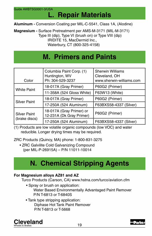
L. Repair Materials
19
M. Primers and Paints
N. Chemical Stripping Agents
Guide AWBTSG0001-3/USA
For Magnesium alloys AZ81 and AZ Turco Products (Carson, CA) www.hstna.com/turco/aviation.cfm •Sprayorbrushonapplication: Water Based Environmentally Advantaged Paint Remover P/N T-6813 or T-6840S •Tanktypestrippingapplication: Diphase Hot Tank Paint Remover P/N T-6813 or T-5668
Color
Columbia Paint Corp. (1)Huntington, WVPh: 304-529-3237
Sherwin WilliamsCleveland, OH www.sherwin-williams.com
White Paint18-017A (Gray Primer) P60G2 (Primer)
11-358A (524 Gloss White) F63W13 (White)
Silver Paint18-017A (Gray Primer) P60G2 (Primer)
17-250A (524 Aluminum) F63BXS58-4337 (Silver)
Silver Paint(brake discs)
18-017A (Gray Primer) or12-231A (Dk Gray Primer)
P60G2 (Primer)
17-250A (524 Aluminum) F63BXS58-4337 (Silver)
(1) Products are low volatile organic compounds (low VOC) and water reducible. Longer drying times may be required.
ZRC Products (Quincy, MA) phone: 1-800-831-3275 •ZRCGalviliteColdGalvanizingCompound (per MIL-P-26915A) – P/N 11011-10014
Aluminum - Conversion Coating per MIL-C-5541, Class 1A, (Alodine)
Magnesium - Surface Pretreatment per AMS-M-3171 (MIL-M-3171) Type III (dip), Type VI (brush on) or Type VIII (dip) IRIDITE 15, MacDermid Inc., Waterbury, CT (800-325-4158)
ClevelandWheels & Brakes
Parker Hannifin Corporation • Aircraft Wheel & Brake Division1160CenterRoad•Avon,Ohio44011
Web site: www.clevelandwheelsandbrakes.com or www.parker.com E-mail: [email protected]•Fax(440)937-5409
Technical Services Hotline: 1-800-BRAKING(1-800-272-5464)•(440)937-1315
AWBTSG0001-3