Embed Size (px)
Citation preview
Technical System CatalogueChillers for IT cooling

Technical System Catalogue/IT infrastructure2
Chillers for IT cooling
The Rittal IT chiller in conjunction with free cooling supplies exceptionally energy- and cost-efficient IT cooling media. The system is specially designed for supplying critical IT applications cooled via LCP, air/water heat exchangers or CRAC systems. In this atmospherically sealed system, redundant, speed-regulated pumps, compressors, emergency cooling or buffer stores ensure optimum opera-tional reliability and fail-safeness. Alongside optional heat recovery from the system, connection to Rittal free cooling recooling systems ensures exceptionally energy-efficient operation. Free cooling uses cold ambient air for cooling, reduces operating costs by up to 80%, extends the service life of components, and increases operational reliability. If the free cooling performance is insufficient, the IT chiller will cut in.
◾ Redundant pumps, speed-controlled◾ Redundant scroll compactor◾ Intelligent control concept◾ Interfaces: SNMP, BACnet◾ Integral or separate free coolers (optional)◾ Integral automatic bypass valve◾ Flow monitor
◾ Operating costs are minimised, thanks to high water inlet temperatures for LCP and CRAC operation
◾ High COP (coefficient of performance)◾ Integration into RiZone

Ambient conditions
3Technical System Catalogue/IT infrastructure
The Liquid Cooling Package and CRAC systems are used to dissipate the thermal load generated by IT equipment and pre-vent the installation site of the IT equipment from overheating. If IT systems are operated at excessive ambient temperatures, this may under certain circumstances lead to malfunctions and restricted operation of the system. The correct system tempera-ture is based on manufacturer-specific information. The Liquid Cooling Packages and CRAC systems only dissipate the ther-mal loads from the IT equipment, but not the thermal loads pro-duced by lighting and other heat sources; these heat loads must be dissipated by other air-conditioning systems. In data centres, the air-conditioning systems are responsible for air quality. Where defined requirements apply to relative humidity in the data centre for operating IT equipment, the most efficient way of achieving this is via the air-conditioning system.
If the air-conditioning system in the data centre is compliant with VDI 6022 (hygiene requirements for air-conditioning sys-tems and devices), ventilation and dehumidification of the intake air to the air-conditioning system can be achieved more effi-ciently and hygienically than with direct IT cooling using an LCP and CRAC system.
If there is a central air-conditioning system for basic climate control installed in the data centre, when project-planning an LCP cooling system to dissipate the thermal loads, the follow-ing information should be obtained:
◾ Relative humidity of the room air (intake air) in %◾ Room air temperature (intake air temperature)◾ Cold water system temperature (where available)
Note: ASHRAE (American Society of Heating, Refrigeration and Air-Conditioning Engineers) recommends server intake air temperatures of between 18°C and 27°C. The selected server intake air temperature should be agreed with the manufacturer of the IT equipment and the operator at the project planning stage.
Based on the prescribed conditions, it is necessary to check whether cooling at the prescribed cold water temperature will cool to below the dew point. This can be checked using the Mollier h-x diagram.
Example of determining the dew pointExample 1:Air intake temperature 22°C, relative humidity 60%, cold water temperature 6°C
50 10 15 20 25
50
45
40
35
30
25
20
15
10
5
0
–5
22
14
–10
–10–15
–10
–5
0
5
10
15
20
25
30
0
10
20
30
40
50
60
70
80
90
–15
0
10 %
20 %
30 %
40 %
50 %
60 %
70 %
80 %
90 %
1
2
Draw a line from the 22°C temperature point to the 60% curve. At this intersection, draw a vertical line to the dew point curve. Next, draw a horizontal line from this intersection point to the temperature scale. The dew point temperature can be read from here. In this example, it is 14°C.
Dew point calculation (°C)
Dew point curve (°C)
h spec. enthalpy (kJ/1 + x kg)
� Dry-bulb temperature (°C)
� Humid air (g/kg)

Sensitive and latent cooling output
Technical System Catalogue/IT infrastructure4
Example of determining the dew pointFor energy-efficient IT cooling, it is crucially important to check the dew point in the prevailing conditions. If the surface tem-perature of the heat exchanger in the LCP or CRAC system is below the dew point, condensation will form on the heat exchanger (see example 2). This will lead to cooling output losses caused by condensation.
The surface temperature of the heat exchanger is calculated as follows:
Example 2:Server exhaust air 42°C, server intake air 22°C, cooler temperature 6°C, P = cooler delta
θ cooler surface ≙ θ inlet + θ return2
50 10 15 20 25
50
45
40
35
30
25
20
15
10
5
0
–5
22
42
6
TP 14
–10
–10–15
–10
–5
0
5
10
20
25
30
0
10
20
30
40
50
60
70
80
90
–15
0
10 %
20 %
30 %
40 %
50 %
60 %
70 %
80 %
90 %P
15
1
2
4
3
Exhaust air temperature (°C)
Wet-bulb temperature (°C)
h spec. enthalpy (kJ/1 + x kg)
� Dry-bulb temperature (°C)
� Dry air (g/kg)
� Sensitive cooling output
Exhaust air temperature (°C)
Wet-bulb temperature (°C)
h spec. enthalpy (kJ/1 + x kg)
� Dry-bulb temperature (°C)
� Dry air (g/kg)
� Sensitive cooling output
� Latent cooling output (losses from condensation)
Cooling output losses arise as a result of condensation on the heat exchanger. This uses energy, but does not lower the server intake air temperature any further. The energy used is only needed for condensation, and is known as the latent cool-ing capacity. On the other hand, if working with cold water inlet temperatures which raise the surface temperature of the heat exchanger above the dew point, energy is only used to cool the server intake air. This is known as the sensitive cooling capacity (see example 3).
Note: The LCP systems are designed to achieve energy-effi-cient IT cooling. The specified rated cooling output always refers to an inlet temperature of 15°C.
Example 3: Server exhaust air 42°C, server intake air 22°C, cooler temperature 15°C
50 10 15 20 25
50
45
40
35
30
25
20
15
10
5
0
–5
22
42
TP 14
–10
–10–15
–10
–5
0
5
10
20
25
30
0
10
20
30
40
50
60
70
80
90
–15
0
10 %
20 %
30 %
40 %
50 %
60 %
70 %
80 %
90 %
15
1
2
3

Cold water system
5Technical System Catalogue/IT infrastructure
Mixed water for LCPIT climate control generally poses a major challenge for the functioning of the cold water system, because the IT equip-ment whose heat loss is dissipated by the cold water system can undergo multiple load changes per minute. This hysteresis is transferred directly to the cold water system, leading to a fluc-tuating dT in the cold water system. If the IT equipment causes a major load step, leading to a rapid increase in heat loss, cold water must be made available immediately by the cold water system. Depending on the distance of the cooling unit from the IT cold water circuit, this can create a very significant dead time, during which no water is available to cool the IT heat loss. Use of a hydraulic circuit can compensate for this response, caused by the IT equipment. By assembling a hydraulic circuit such as an injection circuit, the cold water system is able to counteract the hysteresis generated by the IT equipment.
Dimensioning and design of the pipework for IT climate controlBecause of hysteresis induced by the IT equipment, dT fluctua-tions in the cold water circuit are unavoidable. Fluctuations of between 1 K and 10 K are not uncommon in IT climate control. For this reason, the usual dT of 6 K for a cold water circuit can-not be used to calculate the pipework. With LCPs, the volumet-ric flow required for the rated cooling output is always speci-fied. This specified volumetric flow is used to select the correct pipe dimensions when calculating the pipework. Because very high cooling outputs of up to 55 kW are required for each LCP, in addition to individual sections of pipe it is also advisable to hydraulically regulate the individual connection lines.
Primary circuit pump
Secondary circuit pump
Regulating valves
Mixer with motor
1
2
A
B M
AB
2
1
A
B M
ABLC
P
LCP
LCP
LCP
Secondary circuit
Primary circuit
Bypass line

Cold water system
Technical System Catalogue/IT infrastructure6
Function of the injection circuitThe injection circuit is a tried-and-tested hydraulic circuit which is used whenever it is necessary to make water at the correct temperature available quickly to the equipment. The primary cir-cuit is installed as close as possible to the secondary circuit. The secondary circuit is assembled in the immediate vicinity of the equipment. The cold water is able to circulate permanently in the primary circuit, and is therefore always available when needed by the secondary circuit. Without this circuit, the cold water would first need to cover the entire distance from the pro-ducer to the equipment whenever the flow rate is altered by the equipment. Here too, there may be a significantly lower temper-ature in the primary circuit than in the secondary circuit (pri-mary circuit 6°C/secondary circuit 15°C as a result of mixing).
In this way, the primary circuit pump 1 permanently supplies the secondary circuit with water. The mixer valve in the return limits the volume of water flowing out of the secondary circuit and back into the primary circuit. This therefore limits the incoming water volume as well. The secondary circuit pump allows the entire volume of water required for cooling in the secondary cir-cuit to circulate, and is responsible for mixing the temperatures. Pump 2 allows water from the secondary return to be “injected” into the secondary inlet via the bypass. In this way, cold water from the primary circuit is raised directly to the correct tempera-ture level. The injection circuit is just one example of many pos-sibilities for adapting the cold water system to the requirements of IT climate control.
2
1
60.000 W ≈ 8598 kg/h
8598 kg 21°C
5159 kg 21°C/h
3439 kg 21°C
8598 kg 12°C
8598 kg 15°C
x1
x2
60 %60 %
60 %
40 %
100
%10
0 %
40 %
100
%10
0 %
60 %
3439 kg 6°C
8598 kg 6°C
h
h
h
h
h
h
A
B M
AB
LCP
LCP
LCP
LCP 21°C
15°C
6°C
5159 kg 6°C/h
Circuit 2
Circuit 1
Bypass line

Cold water system
7Technical System Catalogue/IT infrastructure
Operation of the LCP and CRAC system CW units (CW =̂ Chilled Water) requires a cold water system as infrastructure. To this end, a cold water set is installed at a central point which gener-ates cold water to cool the system. When planning/project managing the cold water system, there may often be enor-mous hidden energy saving potential. The more effectively the cold water system is adapted to the required server air intake temperature, the more efficiently the system will operate. The LCP systems operate in an inlet temperature range of 15°C – 18°C, depending on the required air inlet temperature. In LCP systems, the air intake temperatures are regulated, and the chosen air intake temperature for the servers is maintained with a minimal standard deviation. In consequence, the return temperature will fluctuate depending on the load situation in the enclosure. For this reason, when specifying the rated cooling output of the LCP, it is also important to specify the required volume of water for project-planning the hydraulic system (dimensioning of the pipes).
If the LCP systems are to be supplied with an existing cold water system operating at system temperatures of e.g. 6/12°C or 12/18°C, it is advisable to install a mixer or a water/water heat exchanger. For example, if a mixer with an injection circuit is installed upstream of the LCP systems, this is one way of creating the required water inlet temperature for the LCPs. In this way, the spread of 6 K is largely maintained within the system.
There are various hydraulic circuits which may be used depend-ing on the hydraulic layout of the system. Fluctuations in the return temperature are likewise compensated by using a hydraulic circuit The same results are largely achievable by using a water/water heat exchanger. In this application, the sys-tem is divided into two independent hydraulic zones: the pri-mary circuit and the secondary circuit. If there is heavy contami-nation in the system circuit, the heat exchanger prevents the contaminants from being rinsed into the LCP circuit. This appli-cation can also be used where glycol is used in the system circuit, making it possible to dispense with the use of glycol in the LCP circuit.
Note: The mixer with hydraulic circuit is the cheaper, and often technically superior, alternative to the water/water heat exchanger. Selecting the correct hydraulic circuit demands technical knowledge of the system, and must be carried out on-site. An engineering office or refrigeration specialist can assist.
LCP
1
4
5
2
3
6
Connection of the LCPs from the last shut-off valve can be made using the water connection kit D1½" x 1½" (3311.040). It is 1.8 m long.
� Shut-off valve
� Dirt trap
� Tacosetter
� Return
� Inlet
� Manometer
This overview is only intended as guidance for external companies. These services can also be provided by Rittal GmbH's service partners. Please observe the hydrological information for the respective climate control components.Before commissioning, the pipeline system must be adequately rinsed to protect the LCPs from dirt.

Cold water system
Technical System Catalogue/IT infrastructure8
For an efficient cold water supply to the LCP systems, the cold water system must be hydraulically balanced. If the hydraulics are not balanced, the LCP systems will not be supplied homo-geneously with the required volume of cold water (see LCP cold water diagram). This will adversely affect efficient operation. Hydraulic balancing can be achieved via balancing valves. How-ever, by laying the individual connection lines for the LCP sys-tems according to the “Tichelmann” connection principle, this will eliminate the need for hydraulic balancing. With this connec-tion variant, all individual connection lines have the same pres-sure loss.The better-adjusted the hydraulics of a cold water system are, the more accurately the volumes of water required by the cool-ing system can be distributed and made available. Optimum hydraulic distribution often goes hand-in-hand with efficient climate control.
As a general rule, all LCP systems (except LCP passive) include a condensate management system. There is a condensate tray installed in the devices. Additionally, spray eliminators are installed in the 30 kW devices. If condensation occurs as a result of fluctuations in the room conditions, the condensate is discharged into the condensate tray.
The condensate tray has a drain which can be set up to drain into the sewer system. Sensor monitoring of the condensate tray allows an alarm system to be configured in the event of a drainage malfunction. A condensate pump may optionally be installed in the device with LCP systems, but cannot be added retrospectively.
Note: The condensate drain from the LCP systems must not be connected directly to the sewer system. An odour seal must be fitted between the two systems. The conden-sate pump affords no protection from backlogs and wastewater backflow. When connecting the condensate tray to the sewer system, always observe the valid tech-nical regulations.
Cooling distribution without hydraulic balancing
When connected without hydraulic balancing, the LCPs receive differ-ing supplies of cold water. The LCPs furthest from the circulating pump, which have the greatest pressure loss, do not receive a suffi-cient volume of water required for cooling.
Cooling distribution with the Tichelmann system
Connection with the Tichelmann system of pipework is equivalent to hydraulic balancing. All pipe sections in the system have the same pressure loss.
Cooling distribution with hydraulic balancing
With hydraulic balancing, regulating valves throughout the entire pipe-work adjust any pressure losses. All LCPs are supplied with an ade-quate volume of water.
� Circulating pump
� Shut-off valve
� Fine filter
� Return
� Inlet
� Pump pressure
Cooling supply
Pipe friction pressure loss
� Control valve opening
� Control valve
15°C
14
5
6
7
2
3
15°C
14
5
78
2
3
6
15°C
14
5
6
7
2
3
9
10

Master/slave
9Technical System Catalogue/IT infrastructure
Master/slave operating modeIn open bayed enclosure systems which are not separate from one another, cooling units and air/water heat exchangers with e-Comfort control should always be used. These may be linked in master/slave mode via bus cable SK 3124.100:
◾ Simultaneous activation and deactivation of the devices◾ Parallel fault and door limit switch function◾ Even temperature distribution across all sections of the enclo-
sure
� Control cabinets
� Wall-mounted unit
� Roof-mounted unit
� e-Comfort controller
� Door limit switch
� Connection terminals 1 and 2 of the cooling unit
Master/slave combination
1
2
3
7
4
5
5
6
Interface boardThe interface board (SK 3124.200) is an extension for TopTherm cooling units and air/water heat exchangers with e-Comfort controller. In this way it is possible, e.g. to monitor a master/slave combination of up to 10 cooling units. Control is achieved via standardised interfaces RS232 (DB9) and/or RS485, a PLC interface. The extension card is built into a 1 U plastic housing. A voltage supply of 24 V (DC) is required. This can be provided using a Kycon connector.
Further information may be found in our assembly and operat-ing instructions, at www.rittal.com –> Products –> Product search–> SK3124.200.
Warnings and alarms from the interface board:
◾ Interior temperature too high◾ Icing◾ High-pressure sensor◾ Leak◾ Condenser fan defect◾ Evaporator fan defect◾ Compressor defect◾ Sensor failure, condenser temperature◾ Sensor failure, ambient temperature◾ Sensor failure, icing sensor◾ Sensor failure, condensate level◾ Sensor failure, interior temperature◾ Phase missing or incorrect ◾ EPROM error
Master/slave
Technical System Catalogue/IT infrastructure10
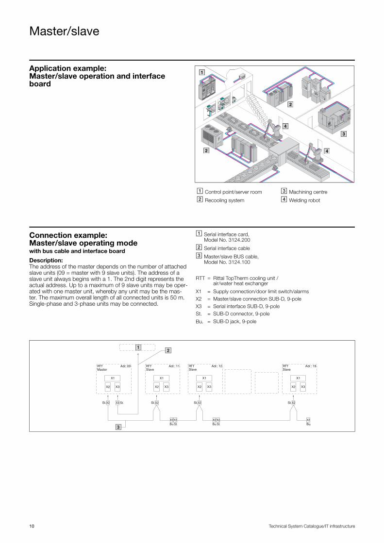
Application example: Master/slave operation and interface board
� Control point/server room
� Recooling system
� Machining centre
� Welding robot
1
2
2
3
4
4
Connection example: Master/slave operating modewith bus cable and interface board
Description:The address of the master depends on the number of attached slave units (09 = master with 9 slave units). The address of a slave unit always begins with a 1. The 2nd digit represents the actual address. Up to a maximum of 9 slave units may be oper-ated with one master unit, whereby any unit may be the mas-ter. The maximum overall length of all connected units is 50 m. Single-phase and 3-phase units may be connected.
� Serial interface card, Model No. 3124.200
� Serial interface cable
� Master/slave BUS cable, Model No. 3124.100
RTT = Rittal TopTherm cooling unit / air/water heat exchanger
X1 = Supply connection/door limit switch/alarmsX2 = Master/slave connection SUB-D, 9-poleX3 = Serial interface SUB-D, 9-poleSt. = SUB-D connector, 9-pole
Bu. = SUB-D jack, 9-pole
RTTMaster
Adr.: 09
X1
X2 X3
RTTSlave
Adr.: 11
X1
X2 X3
Adr.: 12
X1
X2 X3
Adr.: 19
X1
X2 X3
X2 X3 X2X2
X2 X2 X2 X2
X2
X2
St. St. St. St.
St.Bu. Bu.
St.
St.Bu.
1
RTTSlave
RTTSlave
2
3

XWW
0008
2EN
1603
◾ Enclosures◾ Power Distribution◾ Climate Control◾ IT Infrastructure◾ Software & Services
You can find the contact details of all Rittal companies throughout the world here.
www.rittal.com/contact