Embed Size (px)
Citation preview
501 04 2603 00 March 2010
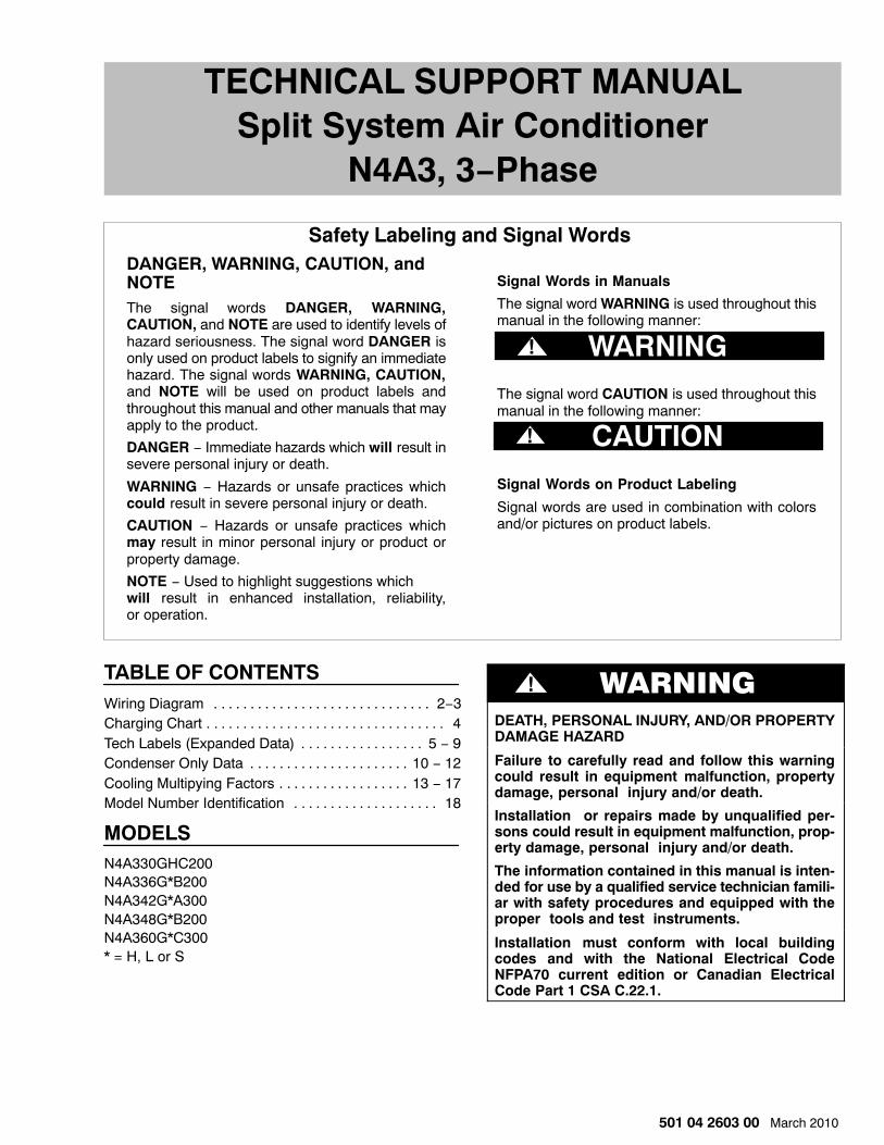
TECHNICAL SUPPORT MANUALSplit System Air Conditioner
N4A3, 3−Phase
DANGER, WARNING, CAUTION, andNOTEThe signal words DANGER, WARNING,CAUTION, and NOTE are used to identify levels ofhazard seriousness. The signal word DANGER isonly used on product labels to signify an immediatehazard. The signal words WARNING, CAUTION,and NOTE will be used on product labels andthroughout this manual and other manuals that mayapply to the product.
DANGER − Immediate hazards which will result insevere personal injury or death.
WARNING − Hazards or unsafe practices whichcould result in severe personal injury or death.
CAUTION − Hazards or unsafe practices whichmay result in minor personal injury or product orproperty damage.
NOTE − Used to highlight suggestions which will result in enhanced installation, reliability,or operation.
Signal Words in Manuals
The signal word WARNING is used throughout thismanual in the following manner:
The signal word CAUTION is used throughout thismanual in the following manner:
Signal Words on Product Labeling
Signal words are used in combination with colorsand/or pictures on product labels.
WARNING
Safety Labeling and Signal Words
!
! CAUTION
WARNING
TABLE OF CONTENTSWiring Diagram 2−3. . . . . . . . . . . . . . . . . . . . . . . . . . . . . . Charging Chart 4. . . . . . . . . . . . . . . . . . . . . . . . . . . . . . . . . Tech Labels (Expanded Data) 5 − 9. . . . . . . . . . . . . . . . . Condenser Only Data 10 − 12. . . . . . . . . . . . . . . . . . . . . . Cooling Multipying Factors 13 − 17. . . . . . . . . . . . . . . . . . Model Number Identification 18. . . . . . . . . . . . . . . . . . . .
MODELSN4A330GHC200N4A336G*B200N4A342G*A300N4A348G*B200N4A360G*C300* = H, L or S
! WARNING
DEATH, PERSONAL INJURY, AND/OR PROPERTYDAMAGE HAZARD
Failure to carefully read and follow this warningcould result in equipment malfunction, propertydamage, personal injury and/or death.
Installation or repairs made by unqualified per-sons could result in equipment malfunction, prop-erty damage, personal injury and/or death.
The information contained in this manual is inten-ded for use by a qualified service technician famili-ar with safety procedures and equipped with theproper tools and test instruments.
Installation must conform with local buildingcodes and with the National Electrical CodeNFPA70 current edition or Canadian ElectricalCode Part 1 CSA C.22.1.
TE
CH
NIC
AL
SU
PP
OR
T M
AN
UA
LS
plit S
ystem A
ir Co
nd
ition
er: N4A
3 3Ph
2501 04 2603 00
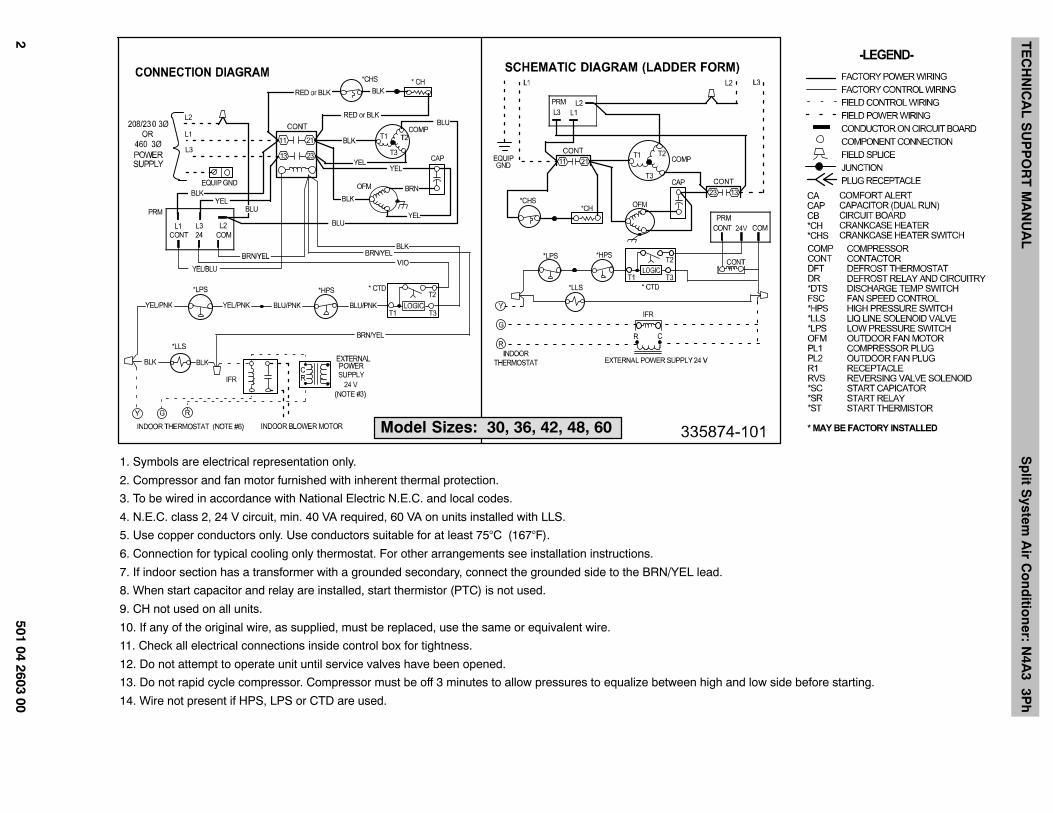
Model Sizes: 30, 36, 42, 48, 60
1. Symbols are electrical representation only.
2. Compressor and fan motor furnished with inherent thermal protection.
3. To be wired in accordance with National Electric N.E.C. and local codes.
4. N.E.C. class 2, 24 V circuit, min. 40 VA required, 60 VA on units installed with LLS.
5. Use copper conductors only. Use conductors suitable for at least 75°C (167°F).
6. Connection for typical cooling only thermostat. For other arrangements see installation instructions.
7. If indoor section has a transformer with a grounded secondary, connect the grounded side to the BRN/YEL lead.
8. When start capacitor and relay are installed, start thermistor (PTC) is not used.
9. CH not used on all units.
10. If any of the original wire, as supplied, must be replaced, use the same or equivalent wire.
11. Check all electrical connections inside control box for tightness.
12. Do not attempt to operate unit until service valves have been opened.
13. Do not rapid cycle compressor. Compressor must be off 3 minutes to allow pressures to equalize between high and low side before starting.
14. Wire not present if HPS, LPS or CTD are used.
TE
CH
NIC
AL
SU
PP
OR
T M
AN
UA
LS
plit S
ystem A
ir Co
nd
ition
er: N4A
3 3Ph
501 04 2603 003
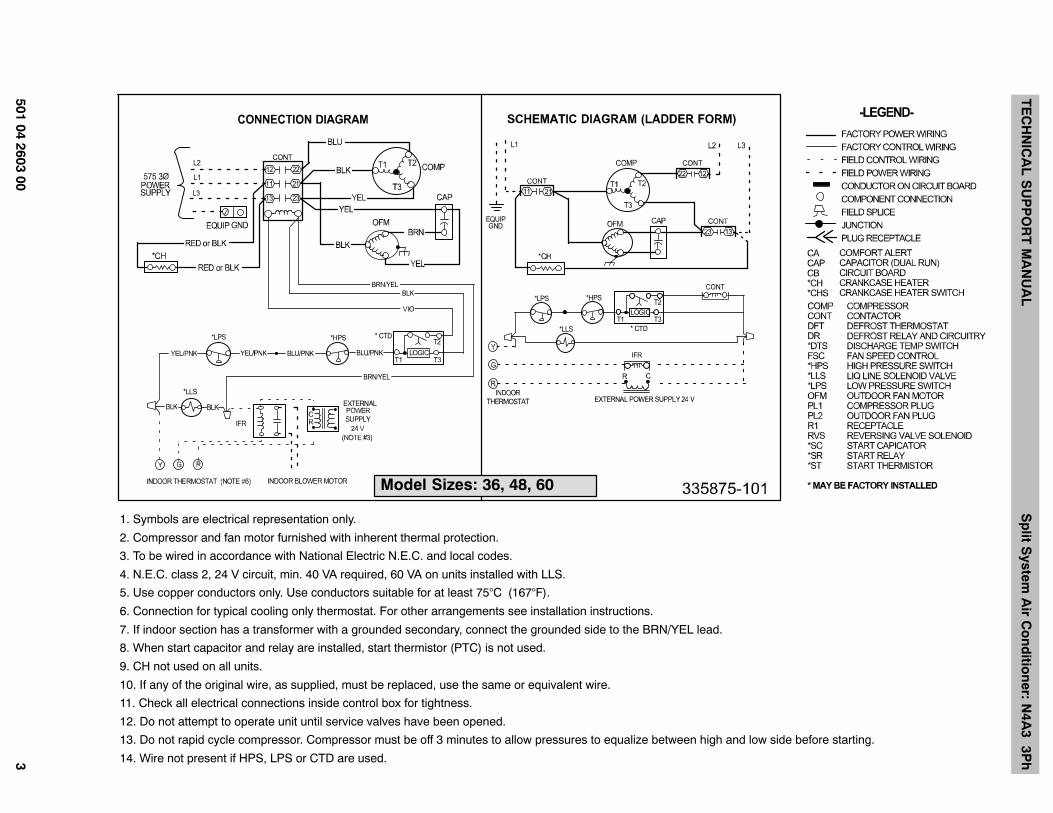
Model Sizes: 36, 48, 60
1. Symbols are electrical representation only.
2. Compressor and fan motor furnished with inherent thermal protection.
3. To be wired in accordance with National Electric N.E.C. and local codes.
4. N.E.C. class 2, 24 V circuit, min. 40 VA required, 60 VA on units installed with LLS.
5. Use copper conductors only. Use conductors suitable for at least 75°C (167°F).
6. Connection for typical cooling only thermostat. For other arrangements see installation instructions.
7. If indoor section has a transformer with a grounded secondary, connect the grounded side to the BRN/YEL lead.
8. When start capacitor and relay are installed, start thermistor (PTC) is not used.
9. CH not used on all units.
10. If any of the original wire, as supplied, must be replaced, use the same or equivalent wire.
11. Check all electrical connections inside control box for tightness.
12. Do not attempt to operate unit until service valves have been opened.
13. Do not rapid cycle compressor. Compressor must be off 3 minutes to allow pressures to equalize between high and low side before starting.
14. Wire not present if HPS, LPS or CTD are used.
TECHNICAL SUPPORT MANUAL Split System Air Conditioner: N4A3 3Ph
4 501 04 2603 00
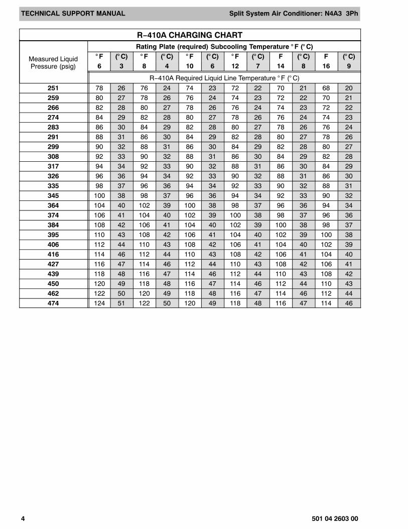
R−410A CHARGING CHART
Measured LiquidPressure (psig)
Rating Plate (required) Subcooling Temperature ° F (° C)° F (° C) ° F (° C) ° F (° C) ° F (° C) F (° C) F (° C)6 3 8 4 10 6 12 7 14 8 16 9
R−410A Required Liquid Line Temperature ° F (° C)
251 78 26 76 24 74 23 72 22 70 21 68 20
259 80 27 78 26 76 24 74 23 72 22 70 21
266 82 28 80 27 78 26 76 24 74 23 72 22
274 84 29 82 28 80 27 78 26 76 24 74 23
283 86 30 84 29 82 28 80 27 78 26 76 24
291 88 31 86 30 84 29 82 28 80 27 78 26
299 90 32 88 31 86 30 84 29 82 28 80 27
308 92 33 90 32 88 31 86 30 84 29 82 28
317 94 34 92 33 90 32 88 31 86 30 84 29
326 96 36 94 34 92 33 90 32 88 31 86 30
335 98 37 96 36 94 34 92 33 90 32 88 31
345 100 38 98 37 96 36 94 34 92 33 90 32
364 104 40 102 39 100 38 98 37 96 36 94 34
374 106 41 104 40 102 39 100 38 98 37 96 36
384 108 42 106 41 104 40 102 39 100 38 98 37
395 110 43 108 42 106 41 104 40 102 39 100 38
406 112 44 110 43 108 42 106 41 104 40 102 39
416 114 46 112 44 110 43 108 42 106 41 104 40
427 116 47 114 46 112 44 110 43 108 42 106 41
439 118 48 116 47 114 46 112 44 110 43 108 42
450 120 49 118 48 116 47 114 46 112 44 110 43
462 122 50 120 49 118 48 116 47 114 46 112 44
474 124 51 122 50 120 49 118 48 116 47 114 46
TE
CH
NIC
AL
SU
PP
OR
T M
AN
UA
LS
plit S
ystem A
ir Co
nd
ition
er: N4A
3 3Ph
501 04 2603 005
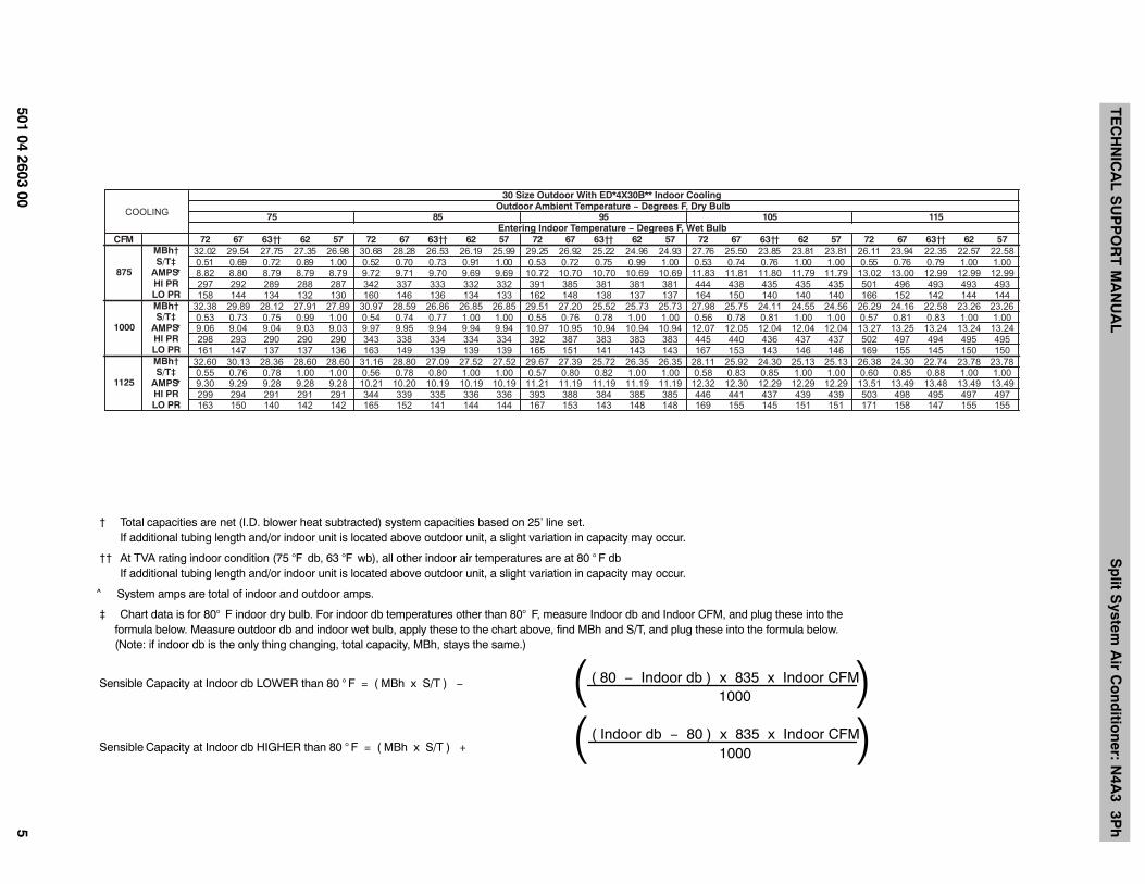
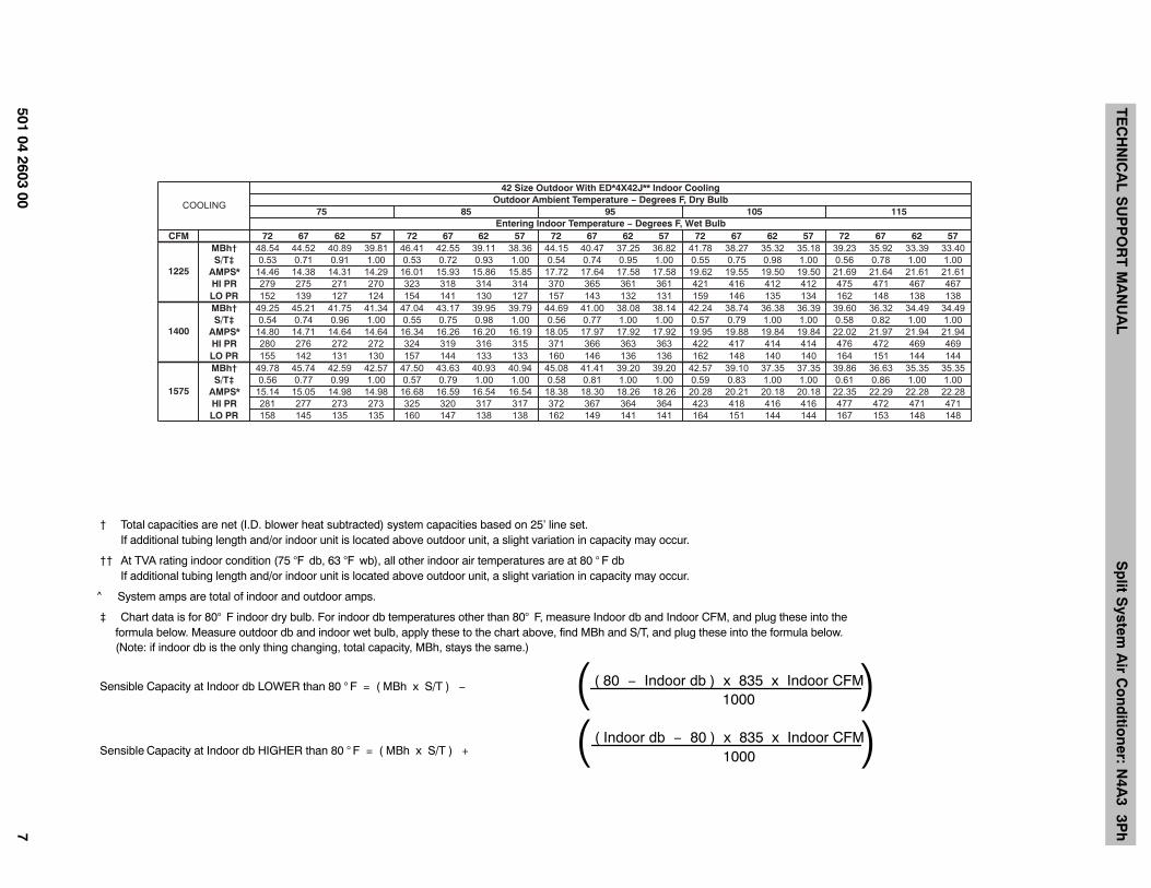
CFM 72 67 63†† 62 57 72 67 63†† 62 57 72 67 63†† 62 57 72 67 63†† 62 57 72 67 63†† 62 57MBh† 32.02 29.54 27.75 27.35 26.98 30.68 28.28 26.53 26.19 25.99 29.25 26.92 25.22 24.96 24.93 27.76 25.50 23.85 23.81 23.81 26.11 23.94 22.35 22.57 22.58S/T‡ 0.51 0.69 0.72 0.89 1.00 0.52 0.70 0.73 0.91 1.00 0.53 0.72 0.75 0.99 1.00 0.53 0.74 0.76 1.00 1.00 0.55 0.76 0.79 1.00 1.00
*AMPS 8.82 8.80 8.79 8.79 8.79 9.72 9.71 9.70 9.69 9.69 10.72 10.70 10.70 10.69 10.69 11.83 11.81 11.80 11.79 11.79 13.02 13.00 12.99 12.99 12.99HI PR 297 292 289 288 287 342 337 333 332 332 391 385 381 381 381 444 438 435 435 435 501 496 493 493 493LO PR 158 144 134 132 130 160 146 136 134 133 162 148 138 137 137 164 150 140 140 140 166 152 142 144 144MBh† 32.38 29.89 28.12 27.91 27.89 30.97 28.59 26.86 26.85 26.85 29.51 27.20 25.52 25.73 25.73 27.98 25.75 24.11 24.55 24.56 26.29 24.16 22.58 23.26 23.26S/T‡ 0.53 0.73 0.75 0.99 1.00 0.54 0.74 0.77 1.00 1.00 0.55 0.76 0.78 1.00 1.00 0.56 0.78 0.81 1.00 1.00 0.57 0.81 0.83 1.00 1.00
*AMPS 9.06 9.04 9.04 9.03 9.03 9.97 9.95 9.94 9.94 9.94 10.97 10.95 10.94 10.94 10.94 12.07 12.05 12.04 12.04 12.04 13.27 13.25 13.24 13.24 13.24HI PR 298 293 290 290 290 343 338 334 334 334 392 387 383 383 383 445 440 436 437 437 502 497 494 495 495LO PR 161 147 137 137 136 163 149 139 139 139 165 151 141 143 143 167 153 143 146 146 169 155 145 150 150MBh† 32.60 30.13 28.36 28.60 28.60 31.16 28.80 27.09 27.52 27.52 29.67 27.39 25.72 26.35 26.35 28.11 25.92 24.30 25.13 25.13 26.38 24.30 22.74 23.78 23.78S/T‡ 0.55 0.76 0.78 1.00 1.00 0.56 0.78 0.80 1.00 1.00 0.57 0.80 0.82 1.00 1.00 0.58 0.83 0.85 1.00 1.00 0.60 0.85 0.88 1.00 1.00
*AMPS 9.30 9.29 9.28 9.28 9.28 10.21 10.20 10.19 10.19 10.19 11.21 11.19 11.19 11.19 11.19 12.32 12.30 12.29 12.29 12.29 13.51 13.49 13.48 13.49 13.49HI PR 299 294 291 291 291 344 339 335 336 336 393 388 384 385 385 446 441 437 439 439 503 498 495 497 497LO PR 163 150 140 142 142 165 152 141 144 144 167 153 143 148 148 169 155 145 151 151 171 158 147 155 155
30 Size Outdoor With ED*4X30B** Indoor CoolingOutdoor Ambient Temperature − Degrees F, Dry Bulb
75Entering Indoor Temperature − Degrees F, Wet Bulb
5115015958
875
COOLING
1000
1125
† Total capacities are net (I.D. blower heat subtracted) system capacities based on 25’ line set. If additional tubing length and/or indoor unit is located above outdoor unit, a slight variation in capacity may occur.
†† At TVA rating indoor condition (75 °F db, 63 °F wb), all other indoor air temperatures are at 80 ° F db If additional tubing length and/or indoor unit is located above outdoor unit, a slight variation in capacity may occur.
^ System amps are total of indoor and outdoor amps.
‡ Chart data is for 80° F indoor dry bulb. For indoor db temperatures other than 80° F, measure Indoor db and Indoor CFM, and plug these into the formula below. Measure outdoor db and indoor wet bulb, apply these to the chart above, find MBh and S/T, and plug these into the formula below. (Note: if indoor db is the only thing changing, total capacity, MBh, stays the same.)
Sensible Capacity at Indoor db LOWER than 80 ° F = ( MBh x S/T ) − ( 80 − Indoor db ) x 835 x Indoor CFM1000( )
Sensible Capacity at Indoor db HIGHER than 80 ° F = ( MBh x S/T ) +( Indoor db − 80 ) x 835 x Indoor CFM
1000( )

TE
CH
NIC
AL
SU
PP
OR
T M
AN
UA
LS
plit S
ystem A
ir Co
nd
ition
er: N4A
3 3Ph
6501 04 2603 00
CFM 72 67 62 57 72 67 62 57 72 67 62 57 72 67 62 57 72 67 62 57MBh† 40.22 36.61 33.42 32.55 38.50 35.00 31.97 31.38 36.66 33.29 30.45 30.12 34.69 31.46 28.86 28.77 32.56 29.49 27.29 27.29
S/T‡ 0.52 0.70 0.91 1.00 0.53 0.72 0.93 1.00 0.54 0.73 0.95 1.00 0.55 0.75 0.98 1.00 0.56 0.77 1.00 1.00
*AMPS 10.73 10.62 10.54 10.51 11.79 11.67 11.59 11.57 12.98 12.86 12.78 12.77 14.34 14.23 14.16 14.16 15.91 15.83 15.78 15.78
HI PR 275 272 270 269 320 317 314 314 369 365 362 362 421 418 415 415 478 474 472 472
LO PR 155 142 131 127 157 144 133 130 159 146 135 134 162 149 138 138 165 151 142 142
MBh† 40.90 37.25 34.19 33.87 39.11 35.57 32.73 32.61 37.20 33.80 31.24 31.27 35.17 31.91 29.83 29.83 32.96 29.88 28.26 28.26
S/T‡ 0.54 0.73 0.95 1.00 0.54 0.75 0.97 1.00 0.55 0.77 1.00 1.00 0.57 0.79 1.00 1.00 0.58 0.81 1.00 1.00
*AMPS 11.00 10.88 10.80 10.79 12.05 11.93 11.85 11.85 13.24 13.12 13.04 13.04 14.60 14.49 14.43 14.43 16.17 16.08 16.04 16.04
HI PR 276 273 271 270 321 318 315 315 370 366 363 364 422 419 416 416 478 475 473 473
LO PR 158 145 134 133 160 147 137 136 162 149 139 139 165 151 143 143 167 154 147 147
MBh† 41.40 37.72 34.90 34.96 39.55 36.00 33.63 33.64 37.60 34.19 32.22 32.23 35.50 32.26 30.70 30.70 33.24 30.19 29.05 29.05
S/T‡ 0.55 0.76 1.00 1.00 0.56 0.78 1.00 1.00 0.57 0.80 1.00 1.00 0.58 0.83 1.00 1.00 0.60 0.86 1.00 1.00
*AMPS 11.26 11.14 11.06 11.06 12.31 12.19 12.12 12.12 13.50 13.38 13.32 13.31 14.85 14.74 14.69 14.69 16.42 16.33 16.30 16.30
HI PR 276 274 271 271 321 318 316 316 370 367 365 365 423 419 417 417 479 476 475 475
LO PR 161 148 138 138 163 150 141 141 165 152 144 144 167 154 148 148 169 156 151 151
Entering Indoor Temperature − Degrees F, Wet Bulb
1050
1200
1350
COOLING
36 Size Outdoor With ED*4X36F** Indoor CoolingOutdoor Ambient Temperature − Degrees F, Dry Bulb
511501595857
† Total capacities are net (I.D. blower heat subtracted) system capacities based on 25’ line set. If additional tubing length and/or indoor unit is located above outdoor unit, a slight variation in capacity may occur.
†† At TVA rating indoor condition (75 °F db, 63 °F wb), all other indoor air temperatures are at 80 ° F db If additional tubing length and/or indoor unit is located above outdoor unit, a slight variation in capacity may occur.
^ System amps are total of indoor and outdoor amps.
‡ Chart data is for 80° F indoor dry bulb. For indoor db temperatures other than 80° F, measure Indoor db and Indoor CFM, and plug these into the formula below. Measure outdoor db and indoor wet bulb, apply these to the chart above, find MBh and S/T, and plug these into the formula below. (Note: if indoor db is the only thing changing, total capacity, MBh, stays the same.)
Sensible Capacity at Indoor db LOWER than 80 ° F = ( MBh x S/T ) − ( 80 − Indoor db ) x 835 x Indoor CFM1000( )
Sensible Capacity at Indoor db HIGHER than 80 ° F = ( MBh x S/T ) +( Indoor db − 80 ) x 835 x Indoor CFM
1000( )
TE
CH
NIC
AL
SU
PP
OR
T M
AN
UA
LS
plit S
ystem A
ir Co
nd
ition
er: N4A
3 3Ph
501 04 2603 007
CFM 72 67 62 57 72 67 62 57 72 67 62 57 72 67 62 57 72 67 62 57MBh† 48.54 44.52 40.89 39.81 46.41 42.55 39.11 38.36 44.15 40.47 37.25 36.82 41.78 38.27 35.32 35.18 39.23 35.92 33.39 33.40
S/T‡ 0.53 0.71 0.91 1.00 0.53 0.72 0.93 1.00 0.54 0.74 0.95 1.00 0.55 0.75 0.98 1.00 0.56 0.78 1.00 1.00
*AMPS 14.46 14.38 14.31 14.29 16.01 15.93 15.86 15.85 17.72 17.64 17.58 17.58 19.62 19.55 19.50 19.50 21.69 21.64 21.61 21.61
HI PR 279 275 271 270 323 318 314 314 370 365 361 361 421 416 412 412 475 471 467 467
LO PR 152 139 127 124 154 141 130 127 157 143 132 131 159 146 135 134 162 148 138 138
MBh† 49.25 45.21 41.75 41.34 47.04 43.17 39.95 39.79 44.69 41.00 38.08 38.14 42.24 38.74 36.38 36.39 39.60 36.32 34.49 34.49
S/T‡ 0.54 0.74 0.96 1.00 0.55 0.75 0.98 1.00 0.56 0.77 1.00 1.00 0.57 0.79 1.00 1.00 0.58 0.82 1.00 1.00
*AMPS 14.80 14.71 14.64 14.64 16.34 16.26 16.20 16.19 18.05 17.97 17.92 17.92 19.95 19.88 19.84 19.84 22.02 21.97 21.94 21.94
HI PR 280 276 272 272 324 319 316 315 371 366 363 363 422 417 414 414 476 472 469 469
LO PR 155 142 131 130 157 144 133 133 160 146 136 136 162 148 140 140 164 151 144 144
MBh† 49.78 45.74 42.59 42.57 47.50 43.63 40.93 40.94 45.08 41.41 39.20 39.20 42.57 39.10 37.35 37.35 39.86 36.63 35.35 35.35
S/T‡ 0.56 0.77 0.99 1.00 0.57 0.79 1.00 1.00 0.58 0.81 1.00 1.00 0.59 0.83 1.00 1.00 0.61 0.86 1.00 1.00
*AMPS 15.14 15.05 14.98 14.98 16.68 16.59 16.54 16.54 18.38 18.30 18.26 18.26 20.28 20.21 20.18 20.18 22.35 22.29 22.28 22.28
HI PR 281 277 273 273 325 320 317 317 372 367 364 364 423 418 416 416 477 472 471 471
LO PR 158 145 135 135 160 147 138 138 162 149 141 141 164 151 144 144 167 153 148 148
Entering Indoor Temperature − Degrees F, Wet Bulb
1225
1400
1575
42 Size Outdoor With ED*4X42J** Indoor CoolingOutdoor Ambient Temperature − Degrees F, Dry Bulb
511501595857COOLING
† Total capacities are net (I.D. blower heat subtracted) system capacities based on 25’ line set. If additional tubing length and/or indoor unit is located above outdoor unit, a slight variation in capacity may occur.
†† At TVA rating indoor condition (75 °F db, 63 °F wb), all other indoor air temperatures are at 80 ° F db If additional tubing length and/or indoor unit is located above outdoor unit, a slight variation in capacity may occur.
^ System amps are total of indoor and outdoor amps.
‡ Chart data is for 80° F indoor dry bulb. For indoor db temperatures other than 80° F, measure Indoor db and Indoor CFM, and plug these into the formula below. Measure outdoor db and indoor wet bulb, apply these to the chart above, find MBh and S/T, and plug these into the formula below. (Note: if indoor db is the only thing changing, total capacity, MBh, stays the same.)
Sensible Capacity at Indoor db LOWER than 80 ° F = ( MBh x S/T ) − ( 80 − Indoor db ) x 835 x Indoor CFM1000( )
Sensible Capacity at Indoor db HIGHER than 80 ° F = ( MBh x S/T ) +( Indoor db − 80 ) x 835 x Indoor CFM
1000( )
TE
CH
NIC
AL
SU
PP
OR
T M
AN
UA
LS
plit S
ystem A
ir Co
nd
ition
er: N4A
3 3Ph
8501 04 2603 00
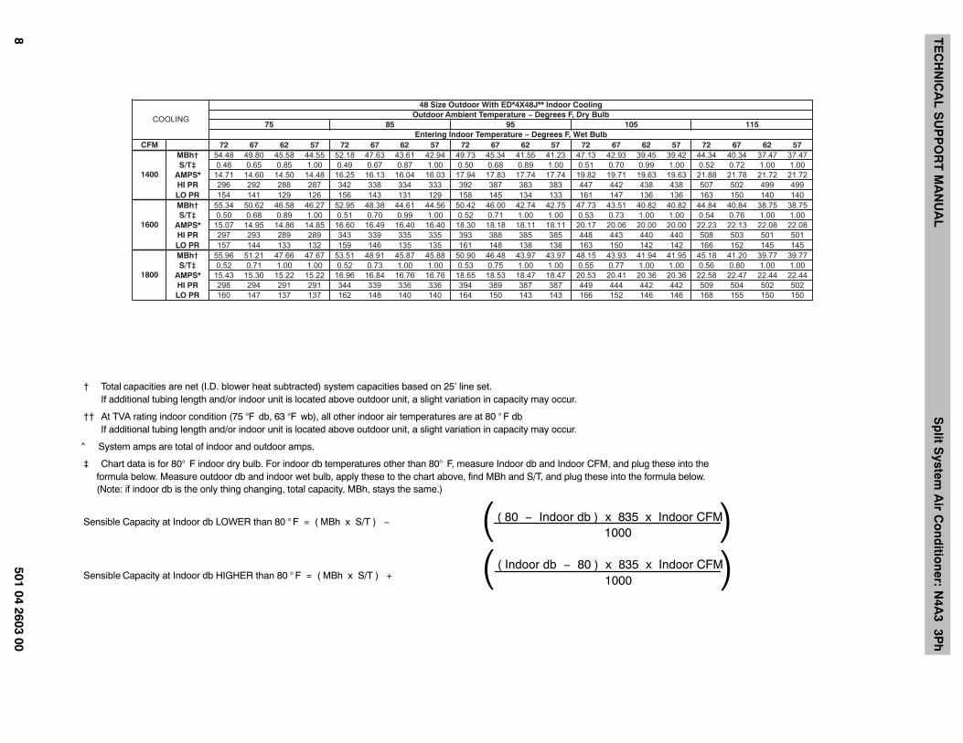
CFM 72 67 62 57 72 67 62 57 72 67 62 57 72 67 62 57 72 67 62 57MBh† 54.48 49.80 45.58 44.55 52.18 47.63 43.61 42.94 49.73 45.34 41.55 41.23 47.13 42.93 39.45 39.42 44.34 40.34 37.47 37.47
S/T‡ 0.48 0.65 0.85 1.00 0.49 0.67 0.87 1.00 0.50 0.68 0.89 1.00 0.51 0.70 0.99 1.00 0.52 0.72 1.00 1.00
*AMPS 14.71 14.60 14.50 14.48 16.25 16.13 16.04 16.03 17.94 17.83 17.74 17.74 19.82 19.71 19.63 19.63 21.88 21.78 21.72 21.72
HI PR 296 292 288 287 342 338 334 333 392 387 383 383 447 442 438 438 507 502 499 499
LO PR 154 141 129 126 156 143 131 129 158 145 134 133 161 147 136 136 163 150 140 140
MBh† 55.34 50.62 46.58 46.27 52.95 48.38 44.61 44.56 50.42 46.00 42.74 42.75 47.73 43.51 40.82 40.82 44.84 40.84 38.75 38.75
S/T‡ 0.50 0.68 0.89 1.00 0.51 0.70 0.99 1.00 0.52 0.71 1.00 1.00 0.53 0.73 1.00 1.00 0.54 0.76 1.00 1.00
*AMPS 15.07 14.95 14.86 14.85 16.60 16.49 16.40 16.40 18.30 18.18 18.11 18.11 20.17 20.06 20.00 20.00 22.23 22.13 22.08 22.08
HI PR 297 293 289 289 343 339 335 335 393 388 385 385 448 443 440 440 508 503 501 501
LO PR 157 144 133 132 159 146 135 135 161 148 138 138 163 150 142 142 166 152 145 145
MBh† 55.96 51.21 47.66 47.67 53.51 48.91 45.87 45.88 50.90 46.48 43.97 43.97 48.15 43.93 41.94 41.95 45.18 41.20 39.77 39.77
S/T‡ 0.52 0.71 1.00 1.00 0.52 0.73 1.00 1.00 0.53 0.75 1.00 1.00 0.55 0.77 1.00 1.00 0.56 0.80 1.00 1.00
*AMPS 15.43 15.30 15.22 15.22 16.96 16.84 16.76 16.76 18.65 18.53 18.47 18.47 20.53 20.41 20.36 20.36 22.58 22.47 22.44 22.44
HI PR 298 294 291 291 344 339 336 336 394 389 387 387 449 444 442 442 509 504 502 502
LO PR 160 147 137 137 162 148 140 140 164 150 143 143 166 152 146 146 168 155 150 150
5115015958Entering Indoor Temperature − Degrees F, Wet Bulb
1400
1600
1800
COOLING
48 Size Outdoor With ED*4X48J** Indoor CoolingOutdoor Ambient Temperature − Degrees F, Dry Bulb
75
† Total capacities are net (I.D. blower heat subtracted) system capacities based on 25’ line set. If additional tubing length and/or indoor unit is located above outdoor unit, a slight variation in capacity may occur.
†† At TVA rating indoor condition (75 °F db, 63 °F wb), all other indoor air temperatures are at 80 ° F db If additional tubing length and/or indoor unit is located above outdoor unit, a slight variation in capacity may occur.
^ System amps are total of indoor and outdoor amps.
‡ Chart data is for 80° F indoor dry bulb. For indoor db temperatures other than 80° F, measure Indoor db and Indoor CFM, and plug these into the formula below. Measure outdoor db and indoor wet bulb, apply these to the chart above, find MBh and S/T, and plug these into the formula below. (Note: if indoor db is the only thing changing, total capacity, MBh, stays the same.)
Sensible Capacity at Indoor db LOWER than 80 ° F = ( MBh x S/T ) − ( 80 − Indoor db ) x 835 x Indoor CFM1000( )
Sensible Capacity at Indoor db HIGHER than 80 ° F = ( MBh x S/T ) +( Indoor db − 80 ) x 835 x Indoor CFM
1000( )
TE
CH
NIC
AL
SU
PP
OR
T M
AN
UA
LS
plit S
ystem A
ir Co
nd
ition
er: N4A
3 3Ph
501 04 2603 009
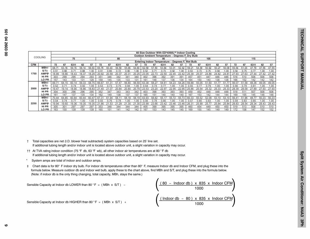
CFM 72 67 63†† 62 57 72 67 63†† 62 57 72 67 63†† 62 57 72 67 63†† 62 57 72 67 63†† 62 57MBh† 68.71 63.16 59.15 58.14 56.63 65.76 60.43 56.59 55.65 54.60 62.59 57.50 53.84 53.01 52.42 59.21 54.39 50.92 50.27 50.09 55.54 51.03 47.79 47.55 47.55S/T‡ 0.51 0.68 0.71 0.88 1.00 0.51 0.69 0.72 0.90 1.00 0.52 0.71 0.73 0.92 1.00 0.53 0.73 0.75 0.94 1.00 0.54 0.75 0.77 1.00 1.00
*AMPS 18.99 18.66 18.43 18.37 18.29 20.92 20.59 20.37 20.31 20.25 23.05 22.73 22.50 22.45 22.42 25.39 25.07 24.86 24.82 24.81 27.93 27.63 27.44 27.42 27.42HI PR 303 299 295 294 293 351 346 342 341 340 402 396 392 391 391 457 451 447 446 446 516 510 506 506 506LO PR 157 143 133 131 128 159 145 135 133 131 161 148 137 136 134 164 150 140 138 138 166 152 142 142 142MBh† 69.71 64.15 60.14 59.33 58.75 66.67 61.31 57.47 56.80 56.59 63.38 58.27 54.61 54.23 54.26 59.88 55.05 51.60 51.77 51.77 56.07 51.58 48.36 49.05 49.05S/T‡ 0.52 0.71 0.74 0.92 1.00 0.53 0.73 0.75 0.94 1.00 0.54 0.74 0.77 1.00 1.00 0.55 0.77 0.79 1.00 1.00 0.56 0.79 0.81 1.00 1.00
*AMPS 19.47 19.14 18.90 18.86 18.83 21.40 21.07 20.84 20.80 20.79 23.53 23.20 22.97 22.95 22.95 25.86 25.54 25.32 25.33 25.33 28.39 28.09 27.89 27.93 27.93HI PR 304 300 296 296 295 352 347 343 343 342 403 398 393 393 393 459 452 448 448 448 518 511 507 508 508LO PR 161 147 137 135 134 162 149 138 137 137 165 151 140 140 140 167 153 142 144 144 169 155 145 148 148MBh† 70.44 64.85 60.84 60.44 60.47 67.31 61.94 58.11 58.18 58.19 63.93 58.82 55.17 55.72 55.73 60.33 55.52 52.08 53.10 53.10 56.41 51.96 48.77 50.23 50.23S/T‡ 0.54 0.74 0.77 1.00 1.00 0.55 0.76 0.78 1.00 1.00 0.56 0.78 0.80 1.00 1.00 0.57 0.80 0.83 1.00 1.00 0.59 0.83 0.85 1.00 1.00
*AMPS 19.94 19.60 19.36 19.35 19.35 21.86 21.53 21.29 21.30 21.30 23.99 23.66 23.42 23.46 23.46 26.31 25.99 25.77 25.84 25.84 28.83 28.54 28.34 28.43 28.43HI PR 305 301 297 297 297 353 348 344 344 344 405 399 395 395 395 460 454 449 450 450 519 513 508 510 510LO PR 163 150 139 139 139 165 151 141 142 142 167 153 143 145 145 169 155 145 149 149 172 158 147 152 152
511501Entering Indoor Temperature − Degrees F, Wet Bulb
1750
2000
2250
COOLING
60 Size Outdoor With ED*4X60L** Indoor CoolingOutdoor Ambient Temperature − Degrees F, Dry Bulb
595857
† Total capacities are net (I.D. blower heat subtracted) system capacities based on 25’ line set. If additional tubing length and/or indoor unit is located above outdoor unit, a slight variation in capacity may occur.
†† At TVA rating indoor condition (75 °F db, 63 °F wb), all other indoor air temperatures are at 80 ° F db If additional tubing length and/or indoor unit is located above outdoor unit, a slight variation in capacity may occur.
^ System amps are total of indoor and outdoor amps.
‡ Chart data is for 80° F indoor dry bulb. For indoor db temperatures other than 80° F, measure Indoor db and Indoor CFM, and plug these into the formula below. Measure outdoor db and indoor wet bulb, apply these to the chart above, find MBh and S/T, and plug these into the formula below. (Note: if indoor db is the only thing changing, total capacity, MBh, stays the same.)
Sensible Capacity at Indoor db LOWER than 80 ° F = ( MBh x S/T ) − ( 80 − Indoor db ) x 835 x Indoor CFM1000( )
Sensible Capacity at Indoor db HIGHER than 80 ° F = ( MBh x S/T ) +( Indoor db − 80 ) x 835 x Indoor CFM
1000( )
TECHNICAL SUPPORT MANUAL Split System Air Conditioner: N4A3 3Ph
10 501 04 2603 00
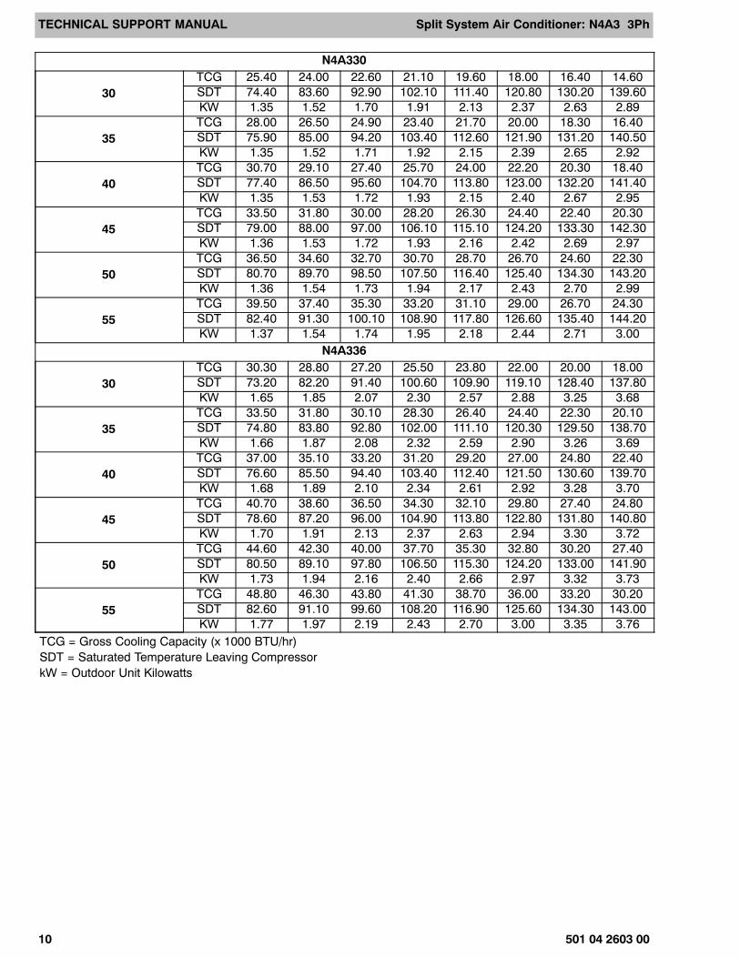
N4A330
30TCG 25.40 24.00 22.60 21.10 19.60 18.00 16.40 14.60SDT 74.40 83.60 92.90 102.10 111.40 120.80 130.20 139.60KW 1.35 1.52 1.70 1.91 2.13 2.37 2.63 2.89
35TCG 28.00 26.50 24.90 23.40 21.70 20.00 18.30 16.40SDT 75.90 85.00 94.20 103.40 112.60 121.90 131.20 140.50KW 1.35 1.52 1.71 1.92 2.15 2.39 2.65 2.92
40TCG 30.70 29.10 27.40 25.70 24.00 22.20 20.30 18.40SDT 77.40 86.50 95.60 104.70 113.80 123.00 132.20 141.40KW 1.35 1.53 1.72 1.93 2.15 2.40 2.67 2.95
45TCG 33.50 31.80 30.00 28.20 26.30 24.40 22.40 20.30SDT 79.00 88.00 97.00 106.10 115.10 124.20 133.30 142.30KW 1.36 1.53 1.72 1.93 2.16 2.42 2.69 2.97
50TCG 36.50 34.60 32.70 30.70 28.70 26.70 24.60 22.30SDT 80.70 89.70 98.50 107.50 116.40 125.40 134.30 143.20KW 1.36 1.54 1.73 1.94 2.17 2.43 2.70 2.99
55TCG 39.50 37.40 35.30 33.20 31.10 29.00 26.70 24.30SDT 82.40 91.30 100.10 108.90 117.80 126.60 135.40 144.20KW 1.37 1.54 1.74 1.95 2.18 2.44 2.71 3.00
N4A336
30TCG 30.30 28.80 27.20 25.50 23.80 22.00 20.00 18.00SDT 73.20 82.20 91.40 100.60 109.90 119.10 128.40 137.80KW 1.65 1.85 2.07 2.30 2.57 2.88 3.25 3.68
35TCG 33.50 31.80 30.10 28.30 26.40 24.40 22.30 20.10SDT 74.80 83.80 92.80 102.00 111.10 120.30 129.50 138.70KW 1.66 1.87 2.08 2.32 2.59 2.90 3.26 3.69
40TCG 37.00 35.10 33.20 31.20 29.20 27.00 24.80 22.40SDT 76.60 85.50 94.40 103.40 112.40 121.50 130.60 139.70KW 1.68 1.89 2.10 2.34 2.61 2.92 3.28 3.70
45TCG 40.70 38.60 36.50 34.30 32.10 29.80 27.40 24.80SDT 78.60 87.20 96.00 104.90 113.80 122.80 131.80 140.80KW 1.70 1.91 2.13 2.37 2.63 2.94 3.30 3.72
50TCG 44.60 42.30 40.00 37.70 35.30 32.80 30.20 27.40SDT 80.50 89.10 97.80 106.50 115.30 124.20 133.00 141.90KW 1.73 1.94 2.16 2.40 2.66 2.97 3.32 3.73
55TCG 48.80 46.30 43.80 41.30 38.70 36.00 33.20 30.20SDT 82.60 91.10 99.60 108.20 116.90 125.60 134.30 143.00KW 1.77 1.97 2.19 2.43 2.70 3.00 3.35 3.76
TCG = Gross Cooling Capacity (x 1000 BTU/hr)SDT = Saturated Temperature Leaving CompressorkW = Outdoor Unit Kilowatts
TECHNICAL SUPPORT MANUAL Split System Air Conditioner: N4A3 3Ph
501 04 2603 00 11
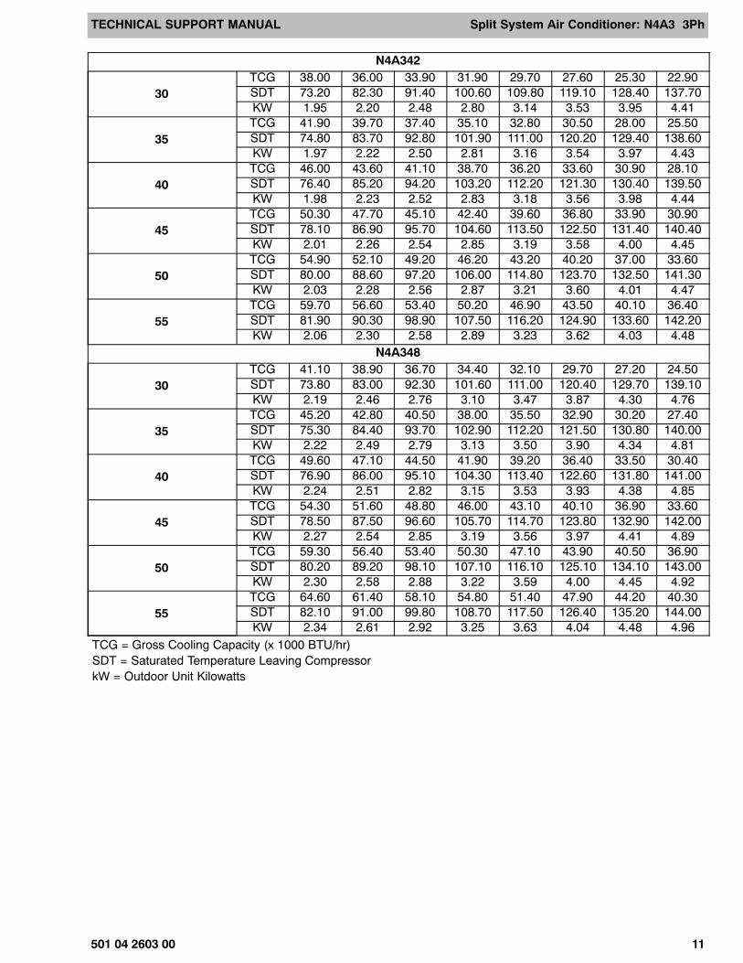
N4A342
30TCG 38.00 36.00 33.90 31.90 29.70 27.60 25.30 22.90SDT 73.20 82.30 91.40 100.60 109.80 119.10 128.40 137.70KW 1.95 2.20 2.48 2.80 3.14 3.53 3.95 4.41
35TCG 41.90 39.70 37.40 35.10 32.80 30.50 28.00 25.50SDT 74.80 83.70 92.80 101.90 111.00 120.20 129.40 138.60KW 1.97 2.22 2.50 2.81 3.16 3.54 3.97 4.43
40TCG 46.00 43.60 41.10 38.70 36.20 33.60 30.90 28.10SDT 76.40 85.20 94.20 103.20 112.20 121.30 130.40 139.50KW 1.98 2.23 2.52 2.83 3.18 3.56 3.98 4.44
45TCG 50.30 47.70 45.10 42.40 39.60 36.80 33.90 30.90SDT 78.10 86.90 95.70 104.60 113.50 122.50 131.40 140.40KW 2.01 2.26 2.54 2.85 3.19 3.58 4.00 4.45
50TCG 54.90 52.10 49.20 46.20 43.20 40.20 37.00 33.60SDT 80.00 88.60 97.20 106.00 114.80 123.70 132.50 141.30KW 2.03 2.28 2.56 2.87 3.21 3.60 4.01 4.47
55TCG 59.70 56.60 53.40 50.20 46.90 43.50 40.10 36.40SDT 81.90 90.30 98.90 107.50 116.20 124.90 133.60 142.20KW 2.06 2.30 2.58 2.89 3.23 3.62 4.03 4.48
N4A348
30TCG 41.10 38.90 36.70 34.40 32.10 29.70 27.20 24.50SDT 73.80 83.00 92.30 101.60 111.00 120.40 129.70 139.10KW 2.19 2.46 2.76 3.10 3.47 3.87 4.30 4.76
35TCG 45.20 42.80 40.50 38.00 35.50 32.90 30.20 27.40SDT 75.30 84.40 93.70 102.90 112.20 121.50 130.80 140.00KW 2.22 2.49 2.79 3.13 3.50 3.90 4.34 4.81
40TCG 49.60 47.10 44.50 41.90 39.20 36.40 33.50 30.40SDT 76.90 86.00 95.10 104.30 113.40 122.60 131.80 141.00KW 2.24 2.51 2.82 3.15 3.53 3.93 4.38 4.85
45TCG 54.30 51.60 48.80 46.00 43.10 40.10 36.90 33.60SDT 78.50 87.50 96.60 105.70 114.70 123.80 132.90 142.00KW 2.27 2.54 2.85 3.19 3.56 3.97 4.41 4.89
50TCG 59.30 56.40 53.40 50.30 47.10 43.90 40.50 36.90SDT 80.20 89.20 98.10 107.10 116.10 125.10 134.10 143.00KW 2.30 2.58 2.88 3.22 3.59 4.00 4.45 4.92
55TCG 64.60 61.40 58.10 54.80 51.40 47.90 44.20 40.30SDT 82.10 91.00 99.80 108.70 117.50 126.40 135.20 144.00KW 2.34 2.61 2.92 3.25 3.63 4.04 4.48 4.96
TCG = Gross Cooling Capacity (x 1000 BTU/hr)SDT = Saturated Temperature Leaving CompressorkW = Outdoor Unit Kilowatts
TECHNICAL SUPPORT MANUAL Split System Air Conditioner: N4A3 3Ph
12 501 04 2603 00
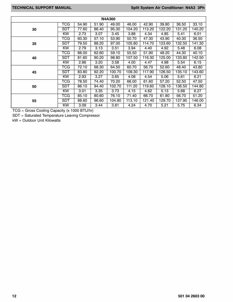
N4A360
30TCG 54.90 51.90 49.00 46.00 42.90 39.80 36.50 33.10SDT 77.60 86.40 95.30 104.20 113.20 122.20 131.20 140.20KW 2.73 3.07 3.45 3.88 4.34 4.85 5.41 6.01
35TCG 60.30 57.10 53.90 50.70 47.30 43.90 40.30 36.50SDT 79.50 88.20 97.00 105.80 114.70 123.60 132.50 141.30KW 2.79 3.13 3.51 3.94 4.40 4.92 5.48 6.08
40TCG 66.00 62.60 59.10 55.50 51.90 48.20 44.30 40.10SDT 81.60 90.20 98.80 107.50 116.30 125.00 133.80 142.50KW 2.86 3.20 3.58 4.00 4.47 4.98 5.54 6.15
45TCG 72.10 68.30 64.50 60.70 56.70 52.60 48.40 43.80SDT 83.80 92.20 100.70 109.30 117.90 126.50 135.10 143.60KW 2.93 3.27 3.65 4.08 4.54 5.06 5.61 6.21
50TCG 78.50 74.40 70.20 66.00 61.60 57.20 52.50 47.50SDT 86.10 94.40 102.70 111.20 119.60 128.10 136.50 144.80KW 3.01 3.35 3.73 4.15 4.62 5.13 5.68 6.27
55TCG 85.10 80.60 76.10 71.40 66.70 61.80 56.70 51.20SDT 88.60 96.60 104.80 113.10 121.40 129.70 137.90 146.00KW 3.09 3.44 3.81 4.24 4.70 5.21 5.75 6.34
TCG = Gross Cooling Capacity (x 1000 BTU/hr)SDT = Saturated Temperature Leaving CompressorkW = Outdoor Unit Kilowatts
TE
CH
NIC
AL
SU
PP
OR
T M
AN
UA
LS
plit S
ystem A
ir Co
nd
ition
er: N4A
3 3Ph
501 04 2603 0013
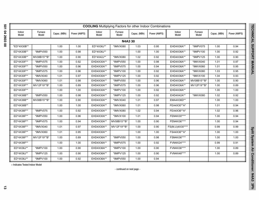
COOLING Multiplying Factors for other Indoor Combinations
IndoorModel
FurnaceModel Capac. (MBh) Power (AMPS)
IndoorModel
FurnaceModel Capac. (MBh) Power (AMPS)
IndoorModel
FurnaceModel Capac. (MBh) Power (AMPS)
N4A3 30
*ED*4X30B** 1.00 1.00 ED*4X36J** *9MVX080 1.03 0.95 EHD4X36A** *9MPV075 1.00 0.94
ED*4X30B** *8MPV050 1.00 0.98 ED*4X36J** 1.00 1.00 EHD4X36A** *9MPV100 1.00 0.92
ED*4X30B** MV08B15**B* 1.00 0.90 ED*4X42J** *9MVX080 1.02 0.92 EHD4X36A** *9MPV125 1.00 0.90
ED*4X30F** *8MPV075 1.00 0.92 EHD4X30A** *8MPV050 1.00 0.98 EHD4X36A** *9MVX040 1.01 0.97
ED*4X30F** *9MPV050 1.00 0.96 EHD4X30A** *8MPV075 1.00 0.94 EHD4X36A** *9MVX060 1.01 0.95
ED*4X30F** *9MPV075 1.00 0.96 EHD4X30A** *8MPV100 1.00 0.92 EHD4X36A** *9MVX080 1.03 0.95
ED*4X30F** *9MVX040 1.01 0.97 EHD4X30A** *8MPV125 1.00 0.92 EHD4X36A** *9MVX100 1.04 0.93
ED*4X30F** *9MVX060 1.01 0.98 EHD4X30A** *9MPV050 1.00 0.96 EHD4X36A** MV08B15**B* 1.00 0.90
ED*4X30F** MV12F19**B* 1.00 0.89 EHD4X30A** *9MPV075 1.00 0.96 EHD4X36A** MV12F19**B* 1.00 0.89
ED*4X30F** 1.00 1.00 EHD4X30A** *9MPV100 1.00 0.92 EHD4X36A** 1.00 1.00
ED*4X36B** *8MPV050 1.00 0.98 EHD4X30A** *9MPV125 1.00 0.92 EHD4X42A** *9MVX080 1.02 0.92
ED*4X36B** MV08B15**B* 1.00 0.90 EHD4X30A** *9MVX040 1.01 0.97 EMA4X36D** 1.00 1.00
ED*4X36B** 1.00 1.00 EHD4X30A** *9MVX060 1.01 0.98 FEA4X30**A* 1.01 0.94
ED*4X36F** *8MPV075 1.00 0.92 EHD4X30A** *9MVX080 1.02 0.94 FEA4X36**A* 1.02 0.96
ED*4X36F** *9MPV050 1.00 0.96 EHD4X30A** *9MVX100 1.01 0.94 FEM4X30**** 1.00 0.94
ED*4X36F** *9MPV075 1.00 0.94 EHD4X30A** MV08B15**B* 1.00 0.90 FEM4X36**** 1.00 0.94
ED*4X36F** *9MVX040 1.01 0.97 EHD4X30A** MV12F19**B* 1.00 0.90 FS(M,U)4X30**** 0.99 0.99
ED*4X36F** *9MVX060 1.01 0.95 EHD4X30A** 1.00 1.00 FSA4X36**A* 1.00 1.00
ED*4X36F** MV12F19**B* 1.00 0.89 EHD4X36A** *8MPV050 1.00 0.98 FSM4X36**** 1.00 1.00
ED*4X36F** 1.00 1.00 EHD4X36A** *8MPV075 1.00 0.92 FVM4X24**** 0.99 0.91
ED*4X36J** *8MPV100 1.00 0.90 EHD4X36A** *8MPV100 1.00 0.90 FVM4X36**** 1.00 0.89
ED*4X36J** *8MPV125 1.00 0.90 EHD4X36A** *8MPV125 1.00 0.90 FVM4X48**** 1.00 0.89
ED*4X36J** *9MPV100 1.00 0.92 EHD4X36A** *9MPV050 1.00 0.94
> Indicates Tested Indoor Model
- continued on next page -
TE
CH
NIC
AL
SU
PP
OR
T M
AN
UA
LS
plit S
ystem A
ir Co
nd
ition
er: N4A
3 3Ph
14501 04 2603 00
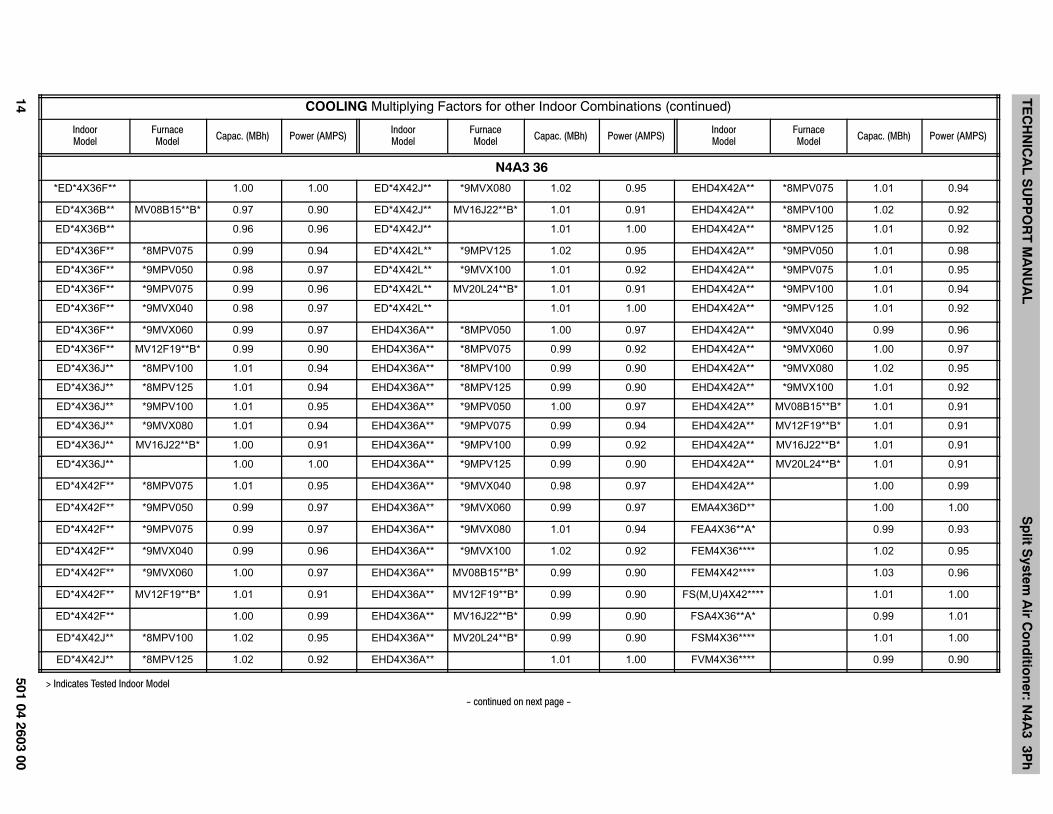
COOLING Multiplying Factors for other Indoor Combinations (continued)
IndoorModel Power (AMPS)Capac. (MBh)
FurnaceModel
IndoorModelPower (AMPS)Capac. (MBh)
FurnaceModel
IndoorModelPower (AMPS)Capac. (MBh)
FurnaceModel
N4A3 36
*ED*4X36F** 1.00 1.00 ED*4X42J** *9MVX080 1.02 0.95 EHD4X42A** *8MPV075 1.01 0.94
ED*4X36B** MV08B15**B* 0.97 0.90 ED*4X42J** MV16J22**B* 1.01 0.91 EHD4X42A** *8MPV100 1.02 0.92
ED*4X36B** 0.96 0.96 ED*4X42J** 1.01 1.00 EHD4X42A** *8MPV125 1.01 0.92
ED*4X36F** *8MPV075 0.99 0.94 ED*4X42L** *9MPV125 1.02 0.95 EHD4X42A** *9MPV050 1.01 0.98
ED*4X36F** *9MPV050 0.98 0.97 ED*4X42L** *9MVX100 1.01 0.92 EHD4X42A** *9MPV075 1.01 0.95
ED*4X36F** *9MPV075 0.99 0.96 ED*4X42L** MV20L24**B* 1.01 0.91 EHD4X42A** *9MPV100 1.01 0.94
ED*4X36F** *9MVX040 0.98 0.97 ED*4X42L** 1.01 1.00 EHD4X42A** *9MPV125 1.01 0.92
ED*4X36F** *9MVX060 0.99 0.97 EHD4X36A** *8MPV050 1.00 0.97 EHD4X42A** *9MVX040 0.99 0.96
ED*4X36F** MV12F19**B* 0.99 0.90 EHD4X36A** *8MPV075 0.99 0.92 EHD4X42A** *9MVX060 1.00 0.97
ED*4X36J** *8MPV100 1.01 0.94 EHD4X36A** *8MPV100 0.99 0.90 EHD4X42A** *9MVX080 1.02 0.95
ED*4X36J** *8MPV125 1.01 0.94 EHD4X36A** *8MPV125 0.99 0.90 EHD4X42A** *9MVX100 1.01 0.92
ED*4X36J** *9MPV100 1.01 0.95 EHD4X36A** *9MPV050 1.00 0.97 EHD4X42A** MV08B15**B* 1.01 0.91
ED*4X36J** *9MVX080 1.01 0.94 EHD4X36A** *9MPV075 0.99 0.94 EHD4X42A** MV12F19**B* 1.01 0.91
ED*4X36J** MV16J22**B* 1.00 0.91 EHD4X36A** *9MPV100 0.99 0.92 EHD4X42A** MV16J22**B* 1.01 0.91
ED*4X36J** 1.00 1.00 EHD4X36A** *9MPV125 0.99 0.90 EHD4X42A** MV20L24**B* 1.01 0.91
ED*4X42F** *8MPV075 1.01 0.95 EHD4X36A** *9MVX040 0.98 0.97 EHD4X42A** 1.00 0.99
ED*4X42F** *9MPV050 0.99 0.97 EHD4X36A** *9MVX060 0.99 0.97 EMA4X36D** 1.00 1.00
ED*4X42F** *9MPV075 0.99 0.97 EHD4X36A** *9MVX080 1.01 0.94 FEA4X36**A* 0.99 0.93
ED*4X42F** *9MVX040 0.99 0.96 EHD4X36A** *9MVX100 1.02 0.92 FEM4X36**** 1.02 0.95
ED*4X42F** *9MVX060 1.00 0.97 EHD4X36A** MV08B15**B* 0.99 0.90 FEM4X42**** 1.03 0.96
ED*4X42F** MV12F19**B* 1.01 0.91 EHD4X36A** MV12F19**B* 0.99 0.90 FS(M,U)4X42**** 1.01 1.00
ED*4X42F** 1.00 0.99 EHD4X36A** MV16J22**B* 0.99 0.90 FSA4X36**A* 0.99 1.01
ED*4X42J** *8MPV100 1.02 0.95 EHD4X36A** MV20L24**B* 0.99 0.90 FSM4X36**** 1.01 1.00
ED*4X42J** *8MPV125 1.02 0.92 EHD4X36A** 1.01 1.00 FVM4X36**** 0.99 0.90
> Indicates Tested Indoor Model
- continued on next page -
TE
CH
NIC
AL
SU
PP
OR
T M
AN
UA
LS
plit S
ystem A
ir Co
nd
ition
er: N4A
3 3Ph
501 04 2603 0015
COOLING Multiplying Factors for other Indoor Combinations (continued)
IndoorModel Power (AMPS)Capac. (MBh)
FurnaceModel
IndoorModelPower (AMPS)Capac. (MBh)
FurnaceModel
IndoorModelPower (AMPS)Capac. (MBh)
FurnaceModel
ED*4X42J** *9MPV100 1.01 0.94 EHD4X42A** *8MPV050 1.00 0.97 FVM4X48**** 1.03 0.94
FVM4X60**** 1.03 0.94
N4A3 42
*ED*4X42J** 1.00 1.00 EHD4X42A** MV16J22**** 1.02 0.96 EP*48J**** *8MPV100 0.99 0.99
EBP42**** 0.99 1.03 EHD4X42A** MV20N26**** 1.04 0.99 EP*48J**** *8MPV125 0.99 0.97
EBP48**** 1.00 1.02 EHD4X48A** 1.01 1.01 EP*48J**** *9MPV100 0.99 0.99
EBV48**** 1.04 0.99 EHD4X48A** *8MPV075 1.01 0.99 EP*48J**** MV16J22**** 1.00 0.98
EBV60**** 1.05 1.00 EHD4X48A** *8MPV100 1.01 0.97 EP*48L**** 0.99 1.01
EBXX48**** 1.02 1.02 EHD4X48A** *8MPV125 1.02 0.98 EP*48L**** *9MPV125 1.00 1.01
ED*4X42F** 0.99 1.01 EHD4X48A** *9MPV075 1.00 0.98 EP*48N**** 0.99 1.01
ED*4X42F** *8MPV075 0.98 0.96 EHD4X48A** *9MPV100 1.01 0.97 EP*48N**** MV20N26**** 1.01 0.99
ED*4X42F** *9MPV075 0.98 0.98 EHD4X48A** *9MPV125 1.02 1.01 EXX*42F**** 0.99 0.99
ED*4X42J** *8MPV100 1.01 0.99 EHD4X48A** MV16J22**** 1.02 0.96 EXX*42F**** *8MPV075 1.00 1.00
ED*4X42J** *8MPV125 1.00 0.96 EHD4X48A** MV20N26**** 1.04 0.99 EXX*42F**** *9MPV075 0.98 0.98
ED*4X42J** MV16J22**** 1.01 0.97 EL*42F**** 0.94 0.97 EXX*42J**** 0.99 0.99
ED*4X42L** 1.00 1.00 EL*42F**** *8MPV075 0.95 0.97 EXX*42J**** *8MPV100 1.00 1.00
ED*4X42L** *9MPV125 1.01 1.01 EL*48F**** 0.96 0.99 EXX*42J**** *8MPV125 1.00 0.98
ED*4X48F** 1.01 1.01 EL*48F**** *8MPV075 0.98 1.00 EXX*42J**** *9MPV100 0.99 0.99
ED*4X48F** *8MPV075 1.01 0.99 EL*48F**** *9MPV075 0.95 0.96 EXX*42J**** MV16J22**** 1.01 0.97
ED*4X48F** *9MPV075 1.00 1.00 EMA4X48D** 1.01 1.01 EXX*48J**** 1.00 1.01
ED*4X48J** 1.01 1.01 EMH42F**** 0.94 0.97 EXX*48J**** *9MPV125 1.01 1.01
ED*4X48J** *8MPV100 1.01 0.97 EMH48F**** 0.98 1.00 EXX*48L**** 1.00 1.01
ED*4X48J** *8MPV125 1.02 0.98 EP*42F**** 0.94 0.97 EXX*48L**** *9MPV125 1.01 1.01
ED*4X48J** *9MPV100 1.02 1.02 EP*42F**** *8MPV075 0.95 0.97 EXX*48N**** 1.00 1.01
> Indicates Tested Indoor Model
- continued on next page -
TE
CH
NIC
AL
SU
PP
OR
T M
AN
UA
LS
plit S
ystem A
ir Co
nd
ition
er: N4A
3 3Ph
16501 04 2603 00
COOLING Multiplying Factors for other Indoor Combinations (continued)
IndoorModel Power (AMPS)Capac. (MBh)
FurnaceModel
IndoorModelPower (AMPS)Capac. (MBh)
FurnaceModel
IndoorModelPower (AMPS)Capac. (MBh)
FurnaceModel
ED*4X48J** MV16J22**** 1.04 0.99 EP*42F**** *9MPV075 0.94 0.97 EXX*48N**** MV20N26**** 1.02 1.01
ED*4X48L** 1.01 1.01 EP*42J**** 0.95 0.99 FEM4X42**** 1.01 0.97
ED*4X48L** *9MPV125 1.02 1.01 EP*42J**** *8MPV100 0.94 0.97 FEM4X48**** 1.04 0.97
EHD4X42A** 1.00 1.00 EP*42J**** *8MPV125 0.95 0.98 FS(M,U)4X42**** 1.00 1.02
EHD4X42A** *8MPV075 1.00 0.98 EP*42J**** *9MPV100 0.92 0.96 FS(M,U)4X48**** 1.02 1.02
EHD4X42A** *8MPV100 1.01 0.97 EP*42J**** MV16J22**** 0.95 0.95 FSM4X36**** 1.01 1.02
EHD4X42A** *8MPV125 1.01 0.97 EP*48F**** 0.96 0.99 FVM4X48**** 1.01 0.93
EHD4X42A** *9MPV075 0.99 0.97 EP*48F**** *8MPV075 0.98 1.00 FVM4X60**** 1.04 0.95
EHD4X42A** *9MPV100 0.99 0.94 EP*48F**** *9MPV075 0.95 0.95
EHD4X42A** *9MPV125 1.01 0.99 EP*48J**** 0.99 1.01
N4A3 48
*ED*4X48J** 1.00 1.00 ED*4X60J** 1.00 0.98 EHD4X60A** *9MPV100 1.01 0.95
ED*4X48F** 0.98 0.98 ED*4X60L** *9MPV125 1.01 0.95 EHD4X60A** *9MPV125 1.01 0.95
ED*4X48J** *8MPV100 0.98 0.94 ED*4X60L** *9MVX100 1.00 0.94 EHD4X60A** *9MVX080 1.01 0.95
ED*4X48J** *8MPV125 0.98 0.92 ED*4X60L** MV20L24**B* 1.01 0.91 EHD4X60A** *9MVX100 1.00 0.94
ED*4X48J** *9MPV100 0.98 0.96 ED*4X60L** 1.01 0.99 EHD4X60A** MV16J22**B* 1.01 0.91
ED*4X48J** *9MVX080 0.99 0.97 EHD4X48A** *8MPV100 1.00 0.96 EHD4X60A** MV20L24**B* 1.01 0.91
ED*4X48J** MV16J22**B* 0.98 0.90 EHD4X48A** *8MPV125 1.00 0.94 EHD4X60A** 1.01 0.99
ED*4X48L** *9MPV125 0.99 0.95 EHD4X48A** *9MPV100 0.99 0.97 EMA4X48D** 0.98 0.98
ED*4X48L** *9MVX100 0.98 0.94 EHD4X48A** *9MPV125 0.99 0.95 FEM4X48**** 1.01 0.95
ED*4X48L** MV20L24**B* 0.99 0.91 EHD4X48A** *9MVX080 0.99 0.97 FEM4X60**** 1.03 0.95
ED*4X48L** 1.00 1.00 EHD4X48A** *9MVX100 0.98 0.94 FS(M,U)4X48**** 0.99 0.97
ED*4X60J** *8MPV100 1.00 0.94 EHD4X48A** MV16J22**B* 1.00 0.92 FS(M,U)4X60**** 1.01 0.99
ED*4X60J** *8MPV125 1.00 0.92 EHD4X48A** MV20L24**B* 1.00 0.92 FVM4X48**** 1.00 0.92
> Indicates Tested Indoor Model
- continued on next page -
TE
CH
NIC
AL
SU
PP
OR
T M
AN
UA
LS
plit S
ystem A
ir Co
nd
ition
er: N4A
3 3Ph
501 04 2603 0017
COOLING Multiplying Factors for other Indoor Combinations (continued)
IndoorModel Power (AMPS)Capac. (MBh)
FurnaceModel
IndoorModelPower (AMPS)Capac. (MBh)
FurnaceModel
IndoorModelPower (AMPS)Capac. (MBh)
FurnaceModel
ED*4X60J** *9MPV100 1.00 0.94 EHD4X48A** 1.00 1.00 FVM4X60**** 1.01 0.91
ED*4X60J** *9MVX080 1.01 0.95 EHD4X60A** *8MPV100 1.01 0.95
ED*4X60J** MV16J22**B* 1.00 0.90 EHD4X60A** *8MPV125 1.01 0.93
N4A3 60
*ED*4X60L** 1.00 1.00 ED*4X60L** MV20L24**B* 0.99 0.97 EHD4X60A** 1.00 1.00
ED*4X60J** *9MVX080 0.97 0.97 EHD4X60A** *9MVX080 0.97 0.97 FEM4X60**** 1.00 0.98
ED*4X60J** MV16J22**B* 0.99 0.97 EHD4X60A** *9MVX100 FS(M,U)4X60****
ED*4X60J** 1.00 1.00 EHD4X60A** MV16J22**B* 1.00 0.96 FVM4X60**** 1.00 0.96
ED*4X60L** *9MVX100 EHD4X60A** MV20L24**B* 0.99 0.97
> Indicates Tested Indoor Model
TECHNICAL SUPPORT MANUAL Split System Air Conditioner: N4A3 3Ph
18 501 04 2603 00
OUTDOOR UNIT MODEL NUMBER IDENTIFICATION GUIDE (single phase)Digit Position: 1 2 3 4 5, 6 7 8 9 10 11 12
Example Part Number: N 4 A 3 18 A K B 1 0 0Product Family2 = R−224 = R−410A REFRIGERANTA = Air ConditionerH = Heat Pump TYPE3 = 13 SEER4 = 14 SEER NOMINAL EFFICIENCY18 = 18,000 BTUH = 1½ tons24 = 24,000 BTUH = 2 tons30 = 30,000 BTUH = 2½ tons36 = 36,000 BTUH = 3 tons42 = 42,000 BTUH = 3½ tons48 = 48,000 BTUH = 4 tons60 = 60,000 BTUH = 5 tons NOMINAL CAPACITYA = Standard GrilleG = Coil Guard GrilleC = Coastal FEATURES
K = 208/230−1−60 VOLTAGE
Sales Code
Engineering Revision
Extra Digit
Extra Digit
ACCESSORIES PART NUMBER IDENTIFICATION GUIDEDigit Position: 1 2 3 4 5 6, 7 8, 9 10, 11
Example Part Number: N A S A 0 0 1 01 C H
N = Non−Branded BRANDING
A = Accessory PRODUCT GROUP
S = Split System (AC & HP) KIT USAGEA = OriginalB = 2nd Generation MAJOR SERIES0 = Generic or Not Applicable
2 = R−22
4 = R−410A REFRIGERANTProduct Identifier Number
Package Quantity
Type of Kit(Example: CH = Crankcase Heater)
International Comfort Products, LLC
Lewisburg, Tennessee 37091 USA