Embed Size (px)
Citation preview
Change for Life
Split Air Conditioner
Owner's ManualResidential Air Conditioners
Thank you for choosing Residential Air Conditioners,please read this owner’s
manual carefully before operation and retain it for future reference.
GWC18KG-K3DNA5AGWC18KG-K3DNA8AGWH18KG-K3DNA8AGWC18KG-K3DNA5BGWH18KG-K3DNA6AGWH18KG-K3DNA5BGWH18KG-K3DNA7BGWC18KG-K3DNA5DGWH18KG-K3DNA7BGWH18KG-K3DNA6BGWH18KG-K3DNA9BGWH18KG-K3DNB2BGWC18KG-K3DNA6AGWH18KG-K3DNB1BGWH18KG-K3DNA9AGWC18KG-K3DNA9AGWC18KG-D3DNA7AGWC18KG-K3DNA7AGWH18KG-K3DNB3AGWH24KG-K3DNB3BGWC18KG-D3DNA5AGWC18KG-K3DNB2AGWH18KG-K3DNA6EGWC18KG-D3DNA5DGWH18KG-K3DNA9EGWC18KG-K3DNB2EGWC18KG-K3DNA9E
GWH18KG-K3DNA5AGWC24KG-K3DNA5AGWH24KG-K3DNA5AGWC24KG-K3DNA8AGWH24KG-K3DNA8AGWH24KG-K3DNA5BGWH24KG-K3DNA6AGWC24KG-K3DNA7AGWH24KG-K3DNA7AGWH24KG-K3DNA6BGWH24KG-K3DNA9BGWC24KG-K3DNA6AGWC24KG-K3DNA5DGWH24KG-K3DNB1BGWC24KG-D3DNA7AGWC24KG-K3DNA9AGWH24KG-K3DNA9AGWH24KG-K3DNB2BGWH18KG-K3DNA5EGWC18KG-K3DNA5EGWH18KG-D3DNA5AGWC18KG-K3DNA5FGWC24KG-K3DNB2AGWH18KG-D3DNA5DGWC18KG-K3DNA5GGWC18KG-D3DNA6E
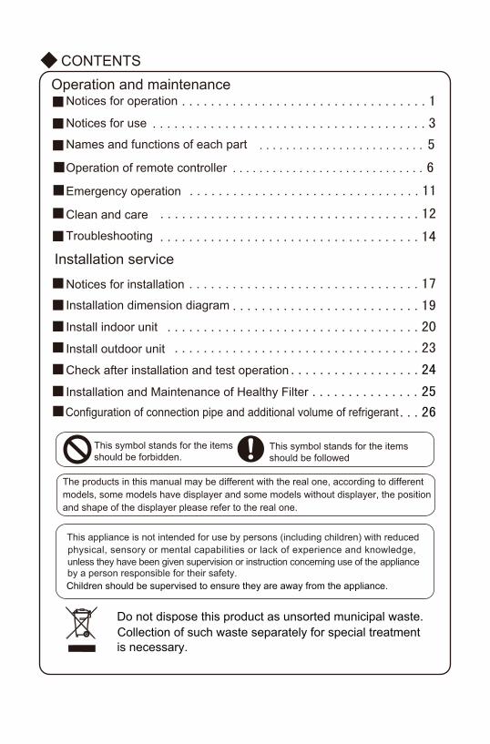
CONTENTS
This symbol stands for the itemsshould be forbidden.
This symbol stands for the items should be followed
■ ..................................1
■
■ ................................11
■ ....................................14
■ ..........................19
■ ...................................20
■ ..................................23
■ ..................24
■ ...............25
■
■ ................................17
■ ....................................12
Operation and maintenanceNotices for operation
Notices for use ......................................3
Names and functions of each part .........................5
■Operation of remote controller .............................6
Clean and care
Troubleshooting
Installation service
Notices for installation
Installation dimension diagram
Install indoor unit
Install outdoor unit
Check after installation and test operation
Emergency operation
Installation and Maintenance of Healthy Filter
Do not dispose this product as unsorted municipal waste. Collection of such waste separately for special treatment is necessary.
The products in this manual may be different with the real one, according to different models, some models have displayer and some models without displayer, the position and shape of the displayer please refer to the real one.
This appliance is not intended for use by persons (including children) with reducedphysical, sensory or mental capabilities or lack of experience and knowledge, unless they have been given supervision or instruction concerning use of the appliance by a person responsible for their safety.Children should be supervised to ensure they are away from the appliance.
■Configuration of connection pipe and additional volume of refrigerant ...26
★
★
★
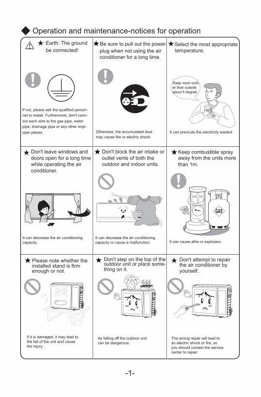
Operation and maintenance-notices for operation
-1-
★ ★Be sure to pull out the power
★
★ ★
★
Earth: The groundbe connected!
If not, please ask the qualified person-nel to install. Furthermore, don't conn-ect each wire to the gas pipe, water pipe, drainage pipe or any other impr-oper places.
plug when not using the air conditioner for a long time.
Otherwise, the accumulated dust may cause fire or electric shock.
Select the most appropriate temperature.
Keep room cool-er than outsideabout 5 degree.
It can preclude the electricity wasted.
Don't leave windows and doors open for a long time while operating the airconditioner.
It can decrease the air conditioningcapacity.
Don't block the air intake oroutlet vents of both the outdoor and indoor units.
It can decrease the air conditioningcapacity or cause a malfunction.
Keep combustible sprayaway from the units morethan 1m.
It can cause afire or explosion.
If it is damaged, it may lead tothe fall of the unit and causethe injury.
Please note whether the installed stand is firmenough or not.
Don't step on the top of theoutdoor unit or place some-thing on it.
As falling off the outdoor unitcan be dangerous.
Don't attempt to repairthe air conditioner byyourself.
The wrong repair will lead toan electric shock or fire, soyou should contact the servicecenter to repair.
-2-
★★
★
★
★
★
★ ★
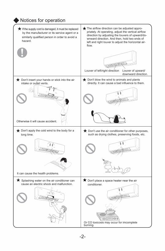
Notices for operationIf the supply cord is damaged, it must be replaced by the manufacturer or its service agent or a similarly qualified person in order to avoid a hazard.
The airflow direction can be adjusted appro-priately. At operating, adjust the vertical airflowdirection by adjusting the louvers of upward/do-wnward direction. And then, hold two ends ofleft and right louver to adjust the horizontal air-flow.
Louver of left/right direction Louver of upward/downward direction.
Don't insert your hands or stick into the airintake or outlet vents.
Otherwise it will cause accident.
Don't blow the wind to animals and plantsdirectly. It can cause a bad influence to them.
Don't apply the cold wind to the body for along time.
It can cause the health problems.
Don't use the air conditioner for other purposes,such as drying clothes, preserving foods, etc.
Splashing water on the air conditioner cancause an electric shock and malfunction.
Don't place a space heater near the air conditioner.
Or CO toxicosis may occur for imcompleteburning.
Anti-cool wind function:In "Heat" mode, under the following three kinds of state, if indoor heat exchanger doesn't arrive at certain temp., indoor fan will not act, in order to prevent cool wind blowing(within2 mins):
1. Heating starts. 2. After Auto Defrost finished. 3. Heating under the low temperature.
*
*
*
*
*
*
Notices for use
Working principle and special functions for cooling
Principle:
Anti-freezing function:
Working principle and special functions for heating
Principle:
Defrosting:
Air conditioner absorbs heat in the room and transmit to outdoor and discharged, so thatindoor ambient temperature decreased, its cooling capacity will increase or decrease byoutdoor ambient temperature.
If the unit is running in COOL mode and in low temperature, there will be frost formed onthe heat exchanger, when indoor heat exchanger temperature decreased below 0 , theindoor unit microcomputer will stop compressor running and protect the unit.
℃
Air conditioner absorbs heat from outdoor and transmits to indoor, in this way to increaseroom temperature. This is the heat pump heating principle, its heating capacity will bereduced due to outdoor temperature decrease.If outdoor temperature becomes very low, please operate with other heating equipments.
When outdoor temperature is low but high humidity, after a long while running, frost willform on outdoor unit, that will effect the heating effect, at this time, the auto defrosting function will act, the heat running will stop for 3-12 mins.During the auto defrosting, the fan motors of indoor unit and outdoor unit will stop.During the defrosting, the indoor indicator flashes, the outdoor unit may emit vapor.This is due to the defrosting, it isn't malfunction.After defrosting finished,the heating will recover automatically.
-3-
-4-
Notices for use
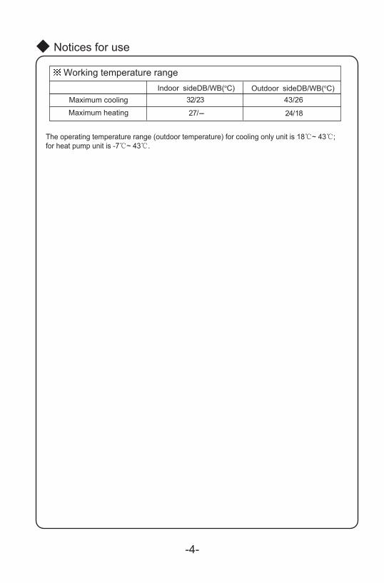
Working temperature range
Maximum cooling
Maximum heating
Indoor sideDB/WB(oC) Outdoor sideDB/WB(oC)32/23
27/---
43/26
24/18
The operating temperature range (outdoor temperature) for cooling only unit is 18℃~ 43℃;for heat pump unit is -7℃~ 43℃.
Air in
Air out
⑶
⑸
⑴
⑷
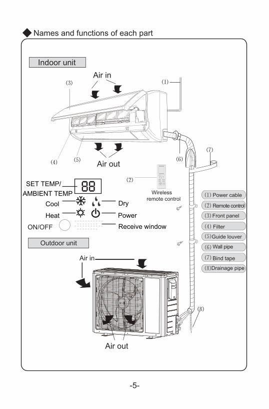
Names and functions of each part
⑹
⑸
⑵
⑻
⑷
⑺
⑶
⑴
Indoor unit
Air out
Outdoor unit
Wirelessremote control
Air in
Power cable
Remote control
Front panel
Filter
Guide louver
Wall pipe
Bind tape
Drainage pipe
⑹
⑺
⑻
Receive windowHeat
Cool
Power
Dry
⑵
ON/OFF
-5-
SET TEMP/AMBIENT TEMP
-6-
FAN AUTOOPER
HEALTHAIR
FILTERTURBO
ON/OFF
X-FAN
HOUR
HUMIDITY
ON/OFF MODE
FAN
X-FAN
TURBO
TEMP TIMER
SLEEP LIGHT
2
11
7
10
13
9
43
12
8
6
14
5
1
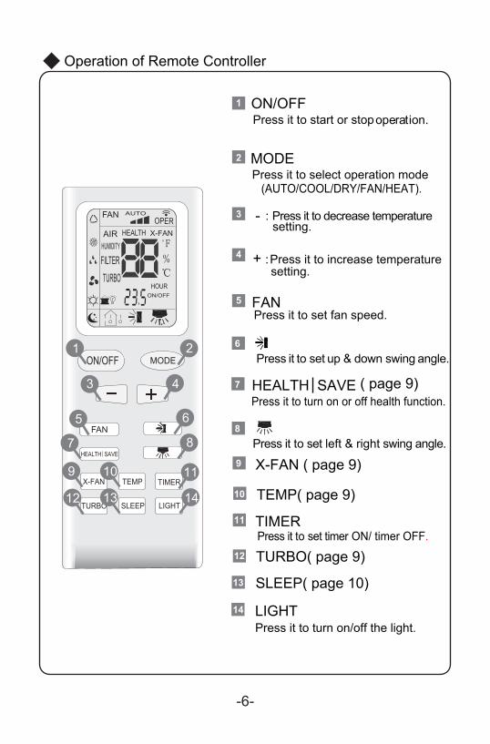
Press it to start or stopON/OFF
operation.
MODE
+
-
Press it to select operation mode(AUTO/COOL/DRY/FAN/HEAT).
: Press it to increase temperaturesetting.
: Press it to decrease temperaturesetting.
FA
HEALTH SAVE
N
Press it to set up & down swing angle.
Press it to turn on/off the light.
TIMER
X-FAN ( page 9)
( page 9)
TEMP( page 9)
TURBO( page 9)
SLEEP( page 10)
LIGHT
Press it to set fan speed.
Press it to set timer ON/ timer OFF.
1
2
Press it to turn on or off health function.7
4
3
5
6
Press it to set left & right swing angle.8
11
9
10
12
13
14
Operation of Remote Controller
Operation of Remote Controller
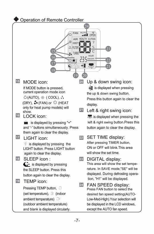
LOCK icon:
MODE icon:
LIGHT icon:
If MODE button is pressed,current operation mode icon
Pressing TEMP button,(set temperature),ambient temperature) (outdoor ambient temperature)and blank is displayed circularly.
(indoor
is displayed by pressing "+"and “-” buttons simultaneously. Pressthem again to clear the display.
is displayed when pressing the left & right swing button.Press thisbutton again to clear the display.
is displayed when pressing the up & down swing button.Press this button again to clear thedisplay.
is displayed by pressing the LIGHT button. Press LIGHT button again to clear the display.
(AUTO), ( COOL), (DRY), (FAN) or (HEAT
only for heat pump models) will show.
15
Left & right swing icon:
20 Up & down swing icon:
After pressing TIMER button, ON or OFF will blink.This areawill show the set time.
SET TIME display:
21
This area will show the set tempe-rature. In SAVE mode,"SE" will be displayed. During defrosting opera- tion, “H1” will be displayed.
DIGITAL display:23
Press FAN button to select thedesired fan speed setting(AUTO-Low-Med-High).Your selection willbe displayed in the LCD windows,except the AUTO fan speed.
FAN SPEED display:24
16
17
SLEEP icon : is displayed by pressing the SLEEP button. Press thisbutton again to clear the display.
18
TEMP icon:19
FAN AUTOOPER
HEALTHAIR
FILTERTURBO
ON/OFF
X-FAN
HOUR
HUMIDITY
19
15
2018
1617
2122
23
24
-7-
22
19
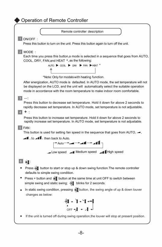
Remote controller description
ON/OFF :
MODE :
+ :
FAN :
1
2
4
3
5
Operation of Remote Controller
-8-
Press this button to turn on the unit. Press this button again to turn off the unit.
Each time you press this button,a mode is selected in a sequence that goes from AUTO,COOL, DRY, FAN,and HEAT *, as the following:
AUTO COOL DRY FAN HEAT *
*Note: Only for models with heating function.After energization, AUTO mode is defaulted. In AUTO mode, the set temperature will notbe displayed on the LCD, and the unit will automatically select the suitable operation mode in accordance with the room temperature to make indoor room comfortable.
Press this button to decrease set temperature. Hold it down for above 2 seconds to rapidly decrease set temperature. In AUTO mode, set temperature is not adjustable.
Press this button to increase set temperature. Hold it down for above 2 seconds torapidly increase set temperature. In AUTO mode, set temperature is not adjustable.
This button is used for setting fan speed in the sequence that goes from AUTO,
to then back to Auto.
,
, ,
Auto
Low speed Medium speed High speed
:6
Press button to start or stop up & down swing function.The remote controller defaults to simple swing condition.
Press + button and button at the same time at unit OFF to switch betweensimple swing and static swing; blinks for 2 seconds.
In static swing condition, pressing
If the unit is turned off during swing operation,the louver will stop at present position.
button, the swing angle of up & down louver changes as below:
●
●
●
●
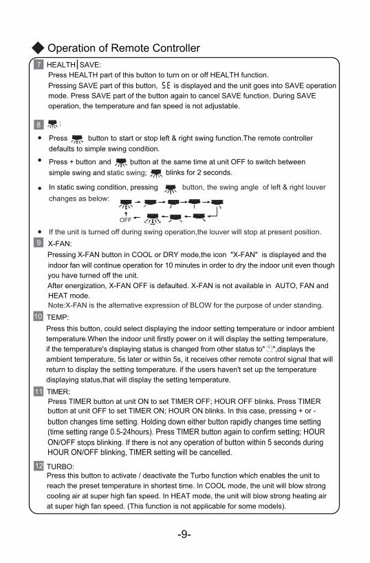
10 TEMP:Press this button, could select displaying the indoor setting temperature or indoor ambient
temperature.When the indoor unit firstly power on it will display the setting temperature, if the temperature's displaying status is changed from other status to" ",displays the ambient temperature, 5s later or within 5s, it receives other remote control signal that will return to display the setting temperature. if the users haven't set up the temperature displaying status,that will display the setting temperature.
HEALTH SAVE:Press HEALTH part of this button to turn on or off HEALTH function.
7
Press TIMER button at unit ON to set TIMER OFF; HOUR OFF blinks. Press TIMERbutton at unit OFF to set TIMER ON; HOUR ON blinks. In this case, pressing + or - button changes time setting. Holding down either button rapidly changes time setting(time setting range 0.5-24hours). Press TIMER button again to confirm setting; HOURON/OFF stops blinking. If there is not any operation of button within 5 seconds during HOUR ON/OFF blinking, TIMER setting will be cancelled.
TIMER:11
X-FAN:
TURBO:
9
12
-9-
:8
Pressing X-FAN button in COOL or DRY mode,the icon "X-FAN" is displayed and the indoor fan will continue operation for 10 minutes in order to dry the indoor unit even though you have turned off the unit.After energization, X-FAN OFF is defaulted. X-FAN is not available in AUTO, FAN and HEAT mode.
Press this button to activate / deactivate the Turbo function which enables the unit toreach the preset temperature in shortest time. In COOL mode, the unit will blow strongcooling air at super high fan speed. In HEAT mode, the unit will blow strong heating airat super high fan speed. (This function is not applicable for some models).
Pressing SAVE part of this button, is displayed and the unit goes into SAVE operationmode. Press SAVE part of the button again to cancel SAVE function. During SAVE operation, the temperature and fan speed is not adjustable.
Operation of Remote Controller
Pres neewteb hctiws ot FFO tinu ta emit emas ehttanottub dnanottub+ssimple swing and static swing;
Press button to start or stop left & right swing function.The remote controller defaults to simple swing condition.
blinks for 2 seconds.
In static swing condition, pressing button, the swing angle of left & right louver changes as below:
●
●
●
If the unit is turned off during swing operation,the louver will stop at present position.●
Note:X-FAN is the alternative expression of BLOW for the purpose of under standing.
SLEEP :
LIGHT:
13
14
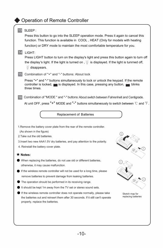
Press this button to go into the SLEEP operation mode. Press it again to cancel this function. This function is available in COOL , HEAT (Only for models with heating function) or DRY mode to maintain the most comfortable temperature for you.
Press LIGHT button to turn on the display's light and press this button again to turn offthe display's light. If the light is turned on , is displayed. If the light is tunrned off, disappears.
-10-
Replacement of Batteries
properly, replace the batteries.
★
●
●
●
●
●
1.Remove the battery cover plate from the rear of the remote controller.
(As shown in the figure)2.Take out the old batteries.
3.Insert two new AAA1.5V dry batteries, and pay attention to the polarity.
4. Reinstall the battery cover plate.
When replacing the batteries, do not use old or different batteries,
If the wireless remote controller will not be used for a long time, please
otherwise, it may cause malfunction.
remove batteries to prevent damage from leaking batteries.
The operation should be performed in its receiving range.
It should be kept 1m away from the TV set or stereo sound sets.
If the wireless remote controller does not operate normally, please take the batteries out and reinsert them after 30 seconds. If it still can't operate
Sketch map for replacing batteries
Notes:
Press "+" and "-" buttons simultaneously to lock or unlock the keypad. If the remote controller is locked, is displayed. In this case, pressing any button, blinksthree times.
At unit OFF, press "+" MODE and "-" buttons simultaneously to switch between ℃ and ℉.
3
2
3
Operation of Remote Controller
Combination of "+" and "-" buttons: About lock15 15
Combination of "MODE " and "-" buttons:About switch between Fahrenheit and Centigrade.16
is on the displayer box.
Displayer indicator light control of indoor unit
Emergency operation
Emergency operation
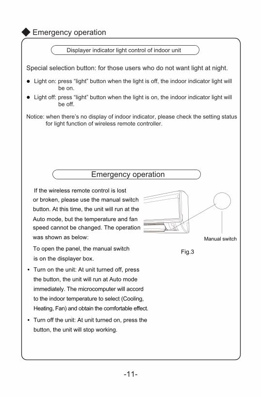
Turn on the unit: At unit turned off, press
the button, the unit will run at Auto mode
immediately. The microcomputer will accord
●
to the indoor temperature to select (Cooling,
Heating, Fan) and obtain the comfortable effect.
Turn off the unit: At unit turned on, press the
button, the unit will stop working.
●
Fig.3
-11-
Manual switch
If the wireless remote control is lost or broken, please use the manual switch
Auto mode, but the temperature and fan
button. At this time, the unit will run at the
To open the panel, the manual switch
speed cannot be changed. The operation
was shown as below:
Special selection button: for those users who do not want light at night.
Light on: press “light” button when the light is off, the indoor indicator light will be on.
Light off: press “light” button when the light is on, the indoor indicator light will be off.
●
●
Notice: when there’s no display of indoor indicator, please check the setting status for light function of wireless remote controller.
℃
●●
●●
●
℃
② Clean the air filter
③
①
(a)
(b)
Clean and care
Caution
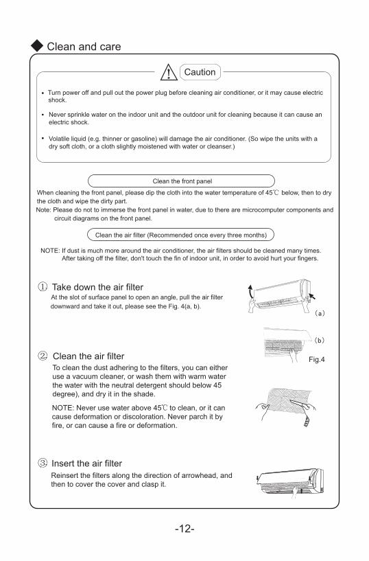
Turn power off and pull out the power plug before cleaning air conditioner, or it may cause electricshock.
Never sprinkle water on the indoor unit and the outdoor unit for cleaning because it can cause anelectric shock.
Volatile liquid (e.g. thinner or gasoline) will damage the air conditioner. (So wipe the units with adry soft cloth, or a cloth slightly moistened with water or cleanser.)
Clean the front panel
Clean the air filter (Recommended once every three months)
NOTE: If dust is much more around the air conditioner, the air filters should be cleaned many times. After taking off the filter, don't touch the fin of indoor unit, in order to avoid hurt your fingers.
Take down the air filterAt the slot of surface panel to open an angle, pull the air filterdownward and take it out, please see the Fig. 4(a, b).
To clean the dust adhering to the filters, you can eitheruse a vacuum cleaner, or wash them with warm waterthe water with the neutral detergent should below 45degree), and dry it in the shade.
NOTE: Never use water above 45 to clean, or it cancause deformation or discoloration. Never parch it byfire, or can cause a fire or deformation.
Insert the air filterReinsert the filters along the direction of arrowhead, andthen to cover the cover and clasp it.
Fig.4
When cleaning the front panel, please dip the cloth into the water temperature of 45 below, then to drythe cloth and wipe the dirty part.Note: Please do not to immerse the front panel in water, due to there are microcomputer components and circuit diagrams on the front panel.
-12-
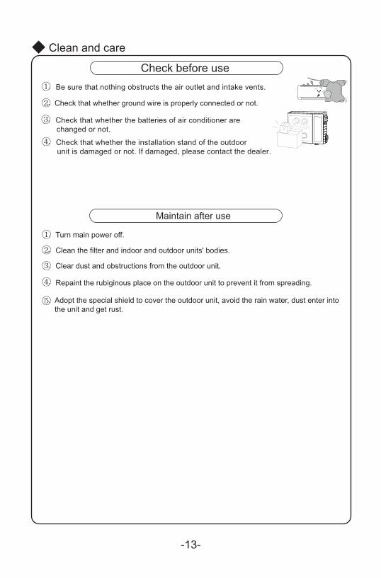
① Be sure that nothing obstructs the air outlet and intake vents.
②
③ Check that whether the batteries of air conditioner are changed or not.
④ Check that whether the installation stand of the outdoor unit is damaged or not. If damaged, please contact the dealer.
① ②
③
④
⑤
Clean and care
Check before use
Check that whether ground wire is properly connected or not.
Maintain after use
Turn main power off.
Clean the filter and indoor and outdoor units' bodies.
Clear dust and obstructions from the outdoor unit.
Repaint the rubiginous place on the outdoor unit to prevent it from spreading.
Adopt the special shield to cover the outdoor unit, avoid the rain water, dust enter intothe unit and get rust.
-13-
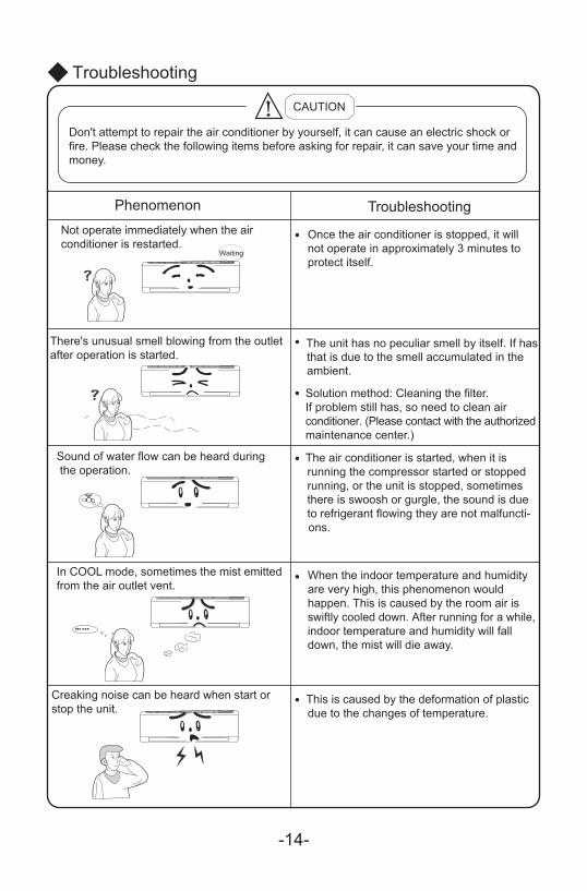
Once the air conditioner is stopped, it willnot operate in approximately 3 minutes toprotect itself.
●
●
●
●
●
●
Troubleshooting
CAUTION
Don't attempt to repair the air conditioner by yourself, it can cause an electric shock orfire. Please check the following items before asking for repair, it can save your time andmoney.
Phenomenon TroubleshootingNot operate immediately when the airconditioner is restarted.
There's unusual smell blowing from the outletafter operation is started.
The unit has no peculiar smell by itself. If hasthat is due to the smell accumulated in the ambient.
Solution method: Cleaning the filter.If problem still has, so need to clean air conditioner. (Please contact with the authorized maintenance center.)
Sound of water flow can be heard during the operation.
The air conditioner is started, when it is running the compressor started or stopped running, or the unit is stopped, sometimes there is swoosh or gurgle, the sound is due to refrigerant flowing they are not malfuncti-ons.
In COOL mode, sometimes the mist emittedfrom the air outlet vent.
When the indoor temperature and humidity are very high, this phenomenon would happen. This is caused by the room air is swiftly cooled down. After running for a while, indoor temperature and humidity will fall down, the mist will die away.
Creaking noise can be heard when start or stop the unit.
This is caused by the deformation of plastic due to the changes of temperature.
Waiting
-14-
●
●
●
●
●
●
●
●
●
●
●
●
●
●
●
●
●
●
●
●
●
●
Troubleshooting
Phenomenon Troubleshooting
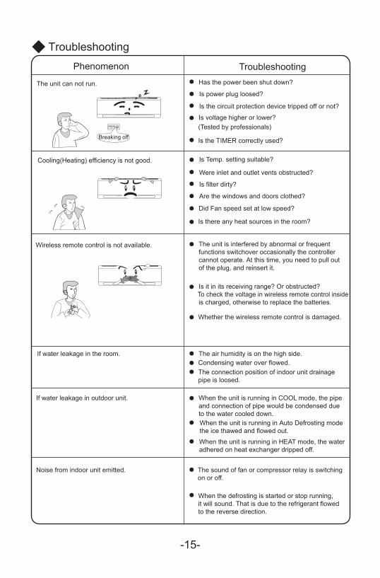
The unit can not run. Has the power been shut down?
Is power plug loosed?
Is the circuit protection device tripped off or not?
Is voltage higher or lower?(Tested by professionals)
Is the TIMER correctly used?
Cooling(Heating) efficiency is not good. Is Temp. setting suitable?
Were inlet and outlet vents obstructed?
Is filter dirty?
Are the windows and doors clothed?
Did Fan speed set at low speed?
Is there any heat sources in the room?
Wireless remote control is not available. The unit is interfered by abnormal or frequentfunctions switchover occasionally the controllercannot operate. At this time, you need to pull outof the plug, and reinsert it.
Is it in its receiving range? Or obstructed?To check the voltage in wireless remote control insideis charged, otherwise to replace the batteries.
Whether the wireless remote control is damaged.
If water leakage in the room. The air humidity is on the high side.Condensing water over flowed.The connection position of indoor unit drainagepipe is loosed.
If water leakage in outdoor unit. When the unit is running in COOL mode, the pipe and connection of pipe would be condensed dueto the water cooled down.When the unit is running in Auto Defrosting mode the ice thawed and flowed out.When the unit is running in HEAT mode, the water adhered on heat exchanger dripped off.
Noise from indoor unit emitted. The sound of fan or compressor relay is switchingon or off.
When the defrosting is started or stop running,it will sound. That is due to the refrigerant flowedto the reverse direction.
Breaking off
-15-
●
●
●
●
TroubleshootingPhenomenon Troubleshooting
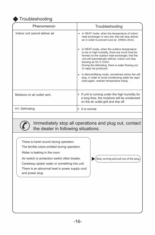
Indoor unit cannot deliver air.
Moisture on air outlet vent
H1: Defrosting
. If unit is running under the high humidity for
● It is normal.
a long time, the moisture will be condensedon the air outlet grill and drip off.
Immediately stop all operations and plug out, contactthe dealer in following situations.
There is harsh sound during operation.The terrible odors emitted during operation.
Water is leaking in the room.
Air switch or protection switch often breaks.
Carelessy splash water or something into unit.There is an abnormal heat in power supply cordand power plug.
Stop running and pull out of the plug.
In HEAT mode, when the temperature of indoorheat exchanger is very low, that will stop deliverair in order to prevent cool air. (Within 2min)
In HEAT mode, when the outdoor temperatureis low or high humidity, there are much frost be formed on the outdoor heat exchanger, that the unit will automatically defrost, indoor unit stop blowing air for 3-12min.During the defrosting, there is water flowing out or vapor be produced.
In dehumidifying mode, sometimes indoor fan willstop, in order to avoid condensing water be vapo-rized again, restrain temperature rising.
-16-
-17-
1.2. Select a position where the condensing water can be easily drained out, and the place
is easily connected for outdoor unit.
4. Can select the place where is strong enough to withstand the full weight and vibration ofthe unit. And will not increase the noise.
5.
6.7.8. Make sure that the indoor unit installation should accord with installation dimension
diagram requirements.
3. Select a location where the children can not reach.
●
●
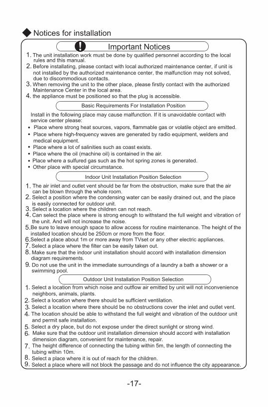
1. The unit installation work must be done by qualified personnel according to the localrules and this manual.
2. Before installating, please contact with local authorized maintenance center, if unit isnot installed by the authorized maintenance center, the malfunction may not solved,due to discommodious contacts.
3. W
4. the appliance must be positioned so that the plug is accessible.
hen removing the unit to the other place, please firstly contact with the authorizedMaintenance Center in the local area.
●●
●
●
Notices for installation
Important Notices
Basic Requirements For Installation Position
Install in the following place may cause malfunction. If it is unavoidable contact with service center please:
Place where strong heat sources, vapors, flammable gas or volatile object are emitted.Place where high-frequency waves are generated by radio equipment, welders and medical equipment.Place where a lot of salinities such as coast exists.Place where the oil (machine oil) is contained in the air.Place where a sulfured gas such as the hot spring zones is generated.Other place with special circumstance.
Indoor Unit Installation Position Selection
The air inlet and outlet vent should be far from the obstruction, make sure that the aircan be blown through the whole room.
Be sure to leave enough space to allow access for routine maintenance. The height of theinstalled location should be 250cm or more from the floor.Select a place about 1m or more away from TVset or any other electric appliances.Select a place where the filter can be easily taken out.
. Do not use the unit in the immediate surroundings of a laundry a bath a shower or aswimming pool.
9
1. Select a location from which noise and outflow air emitted by unit will not inconvenience neighbors, animals, plants.
2. Select a location where there should be sufficient ventilation.3. Select a location where there should be no obstructions cover the inlet and outlet vent.4. The location should be able to withstand the full weight and vibration of the outdoor unit and permit safe installation.5. Select a dry place, but do not expose under the direct sunlight or strong wind.6.
7.
8.9.
Outdoor Unit Installation Position Selection
Make sure that the outdoor unit installation dimension should accord with installation dimension diagram, convenient for maintenance, repair.The height difference of connecting the tubing within 5m, the length of connecting thetubing within 10m.Select a place where it is out of reach for the children.Select a place where will not block the passage and do not influence the city appearance.
-18-
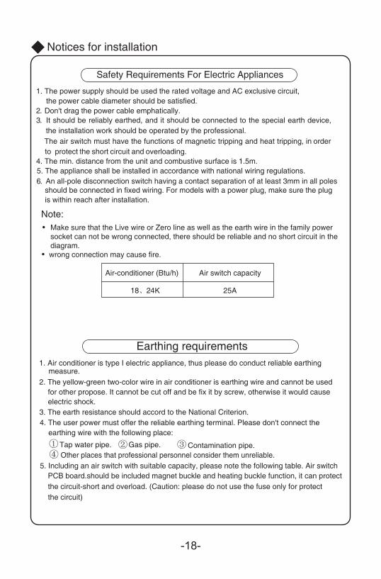
Note:Make sure that the Live wire or Zero line as well as the earth wire in the family power socket can not be wrong connected, there should be reliable and no short circuit in the diagram.wrong connection may cause fire.
●
●
4. The min. distance from the unit and combustive surface is 1.5m.
1. The power supply should be used the rated voltage and AC exclusive circuit,the power cable diameter should be satisfied.
2. Don't drag the power cable emphatically.3.
① ② ③ ④
1. Air conditioner is type I electric appliance, thus please do conduct reliable earthingmeasure.
2. The yellow-green two-color wire in air conditioner is earthing wire and cannot be usedfor other propose. It cannot be cut off and be fix it by screw, otherwise it would causeelectric shock.
3. The earth resistance should accord to the National Criterion.4. The user power must offer the reliable earthing terminal. Please don't connect the
earthing wire with the following place:
Tap water pipe. Gas pipe. Contamination pipe.Other places that professional personnel consider them unreliable.
5. The appliance shall be installed in accordance with national wiring regulations. An all-pole disconnection switch having a contact separation of at least 3mm in all poles should be connected in fixed wiring. For models with a power plug, make sure the plugis within reach after installation.
It should be reliably earthed, and it should be connected to the special earth device,the installation work should be operated by the professional. The air switch must have the functions of magnetic tripping and heat tripping, in order to protect the short circuit and overloading.
6.
5. Including an air switch with suitable capacity, please note the following table. Air switchPCB board.should be included magnet buckle and heating buckle function, it can protectthe circuit-short and overload. (Caution: please do not use the fuse only for protectthe circuit)
Notices for installation
Safety Requirements For Electric Appliances
Earthing requirements
18、24K 25A
Air switch capacityAir-conditioner (Btu/h)

Space to the wall
200cm Above
50cm Above
Installation dimension diagram
Installation dimension diagram
Space to the ceiling
Space to the wall
Space to the wall
Air outlet sideSpace to the floor
AboveAbove
Above 15cm Above
Above
Space to the obstruction
Air outlet side
Space to the wall
Air inlet side
30cm Above
50cm Above
evob50
cm A
The dimensions of the space necessary for correct installation of the appliance including the minimum permissible distances to adjacent structures
●
-19-
15cm
15cm
250 cm
300cm
-20-
Install indoor unit
24K:
18K:
mm0 5 1
mm mm
mm0 5 1
Fig.5
Wall WallMark on the middle of it Gradienter
Left Right
(Rear piping hole) (Rear piping hole)
Spaceto thewall
above
Spaceto thewall
above
1 50mm
mm5 5 mm5 5
mm1 5 0
Wall Wall Mark on the middle of it Gradienter
Left Right
(Rear piping hole) (Rear piping hole)
Spaceto thewall
above
Spaceto thewall
above
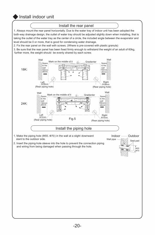
Install the rear panel 1. Always mount the rear panel horizontally. Due to the water tray of indoor unit has been adopted the both-way drainage design, the outlet of water tray should be adjusted slightly down when installing, that is taking the outlet of the water tray as the center of a circle, the included angle between the evaporator and level should be 0 or more, that is good for condensing water drainage. 2. Fix the rear panel on the wall with screws. (Where is pre-covered with plastic granula) 3. Be sure that the rear panel has been fixed firmly enough to withstand the weight of an adult of 60kg, further more, the weight should be evenly shared by each screw.
Install the piping hole
1. Make the piping hole (Ф55、Ф70) in the wall at a slight downward slant to the outdoor side.
2. Insert the piping-hole sleeve into the hole to prevent the connection piping and wiring from being damaged when passing through the hole.
Indoor Outdoor Wall pipe
Seal pad
Ф Ф
Ф70 Ф70
Ф55Ф70
-21-
Install indoor unit
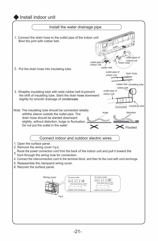
Connect indoor and outdoor electric wires 1. Open the surface panel.2. Remove the wiring cover Fig.6.
3. Route the power connection cord from the back of the indoor unit and pull it toward the
4. Connect the interconnection cord to the terminal block, and then fix the cord with cord anchorge.5. Reassemble the clampand wiring cover.
front through the wiring hole for connection.
6. Recover the surface panel.
Install the water drainage pipe
N(1) 2 3blue black brown yellow-
green
outdoor unit connection
N(1) 2 3blue black brown yellow-
green
outdoor unit connection
for some model for some model
Fig.6
Wiring cover
1.
2.
3.
Connect the drain hose to the outlet pipe of the indoor unit.Bind the joint with rubber belt.
Put the drain hose into insulating tube.
Wrap the insulating tube with wide rubber belt to prevent the shift of insulating tube. Slant the drain hose downward slightly for smooth drainage of condensate.
bulge distortion
outlet pipe of indoor unit
insulating tubeconnected
insulating tube
drain hoseoutlet pipe of indoor unit
drain hose
outlet pipe of indoor unit
outlet pipe of indoor unit
rubber belt
rubber beltrubber belt
Flooded
Note: The insulating tube should be connected reliably withthe sleeve outside the outlet pipe. The drain hose should be slanted downward slightly, without distortion, bulge or fluctuation. Do not put the outlet in the water.
-22-
●
●
● After tighten the screw, slight pull the wire and confirm whether is it firm or not.● ● The cover plate must be fixed, and tighten the connection wire, if it is poor installed, that
Install indoor unit
NOTE:When connecting the electric wire if the wire length is not enough, please contact withthe authorized service shop to buy a exclusive electric wire that is long enough and thejoint on the wire are not allowed.
The electric wiring must be correctly connected, wrong connection may cause spare partsmalfunction.Tighten the terminal screw in order to prevent loose.
If the earth wire is wrong connection, that may cause electric shock.
the dust, moisture may enter in or the connection terminal will be affected by outside force,and will cause fire or electric shock.
右后
4.
2.
3.
●
1.
⑴ ⑵
1.2.
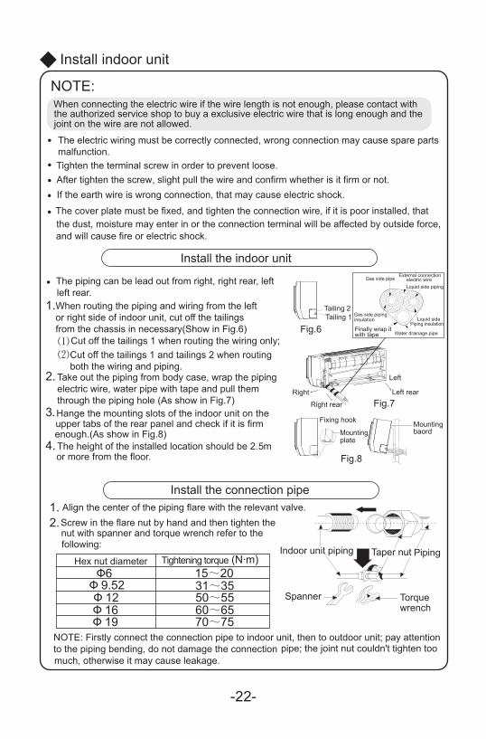
Install the indoor unit
The piping can be lead out from right, right rear, leftleft rear.When routing the piping and wiring from the leftor right side of indoor unit, cut off the tailingsfrom the chassis in necessary(Show in Fig.6)
Cut off the tailings 1 when routing the wiring only;Cut off the tailings 1 and tailings 2 when routingboth the wiring and piping.
Take out the piping from body case, wrap the pipingelectric wire, water pipe with tape and pull themthrough the piping hole (As show in Fig.7)Hange the mounting slots of the indoor unit on theupper tabs of the rear panel and check if it is firmenough.(As show in Fig.8)The height of the installed location should be 2. mor more from the floor.
Install the connection pipeAlign the center of the piping flare with the relevant valve.Screw in the flare nut by hand and then tighten thenut with spanner and torque wrench refer to the following:
NOTE: Firstly connect the connection pipe to indoor unit, then to outdoor unit; pay attentionto the piping bending, do not damage the connection pipe; the joint nut couldn't tighten toomuch, otherwise it may cause leakage.
Spanner Torque wrench
PipingTaper nutIndoor unit piping
Fig.8
Mountingplate
Fixing hook Mounting baord
Right
Right rear Fig.7Left rear
Left
Fig.6Tailing 1Tailing 2
Finally wrap itwith tape
Gas side pipinginsulation
Water drainage pipe
Liquid sidePiping insulation
Gas side pipeExternal connection
electric wireLiquid side piping
(N·m)Ф6
Ф 9.52Ф 12
31~3515~20
50~55Ф 16 60~65Ф 19 70~75
Hex nut diameter Tightening torque
5
Ø
-23-
Air purging and leakage test
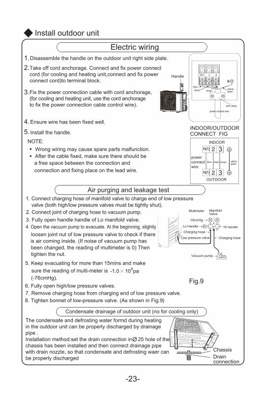
Condensate drainage of outdoor unit (no for cooling only)
The condensate and defrosting water formd during heating in the outdoor unit can be properly discharged by drainagepipe .Installation method:set the drain connection in 25 hole of the chassis has been installed and then connect drainage pipe with drain nozzle, so that condensate and defrosting waer can be properly discharged
ChassisDrainconnection
●
●
Install outdoor unit
Electric wiring
NOTE:Wrong wiring may cause spare parts malfunction.After the cable fixed, make sure there should be a free space between the connection andconnection and fixing place on the lead wire.
3.
4.5.
1.2.
Disassemble the handle on the outdoor unit right side plate.
Take off cord anchorage. Connect and fix power connectcord (for cooling and heating unit,connect and fix powerconnect cord)to terminal block.
Fix the power connection cable with cord anchorage,(for cooling and heating unit, use the cord anchorageto fix the power connection cable control wire).
Ensure wire has been fixed well.
Install the handle.
5 -1.0 10 pa(-76cmHg)..
1. Connect charging hose of manifold valve to charge end of low pressure valve (both high/low pressure valves must be tightly shut).
2. Connect joint of charging hose to vacuum pump.3. Fully open handle handle of Lo manifold valve.4. Open the vacuum pump to evacuate. At the beginning, slightly
loosen joint nut of low pressure valve to check if there is air coming inside. (If noise of vacuum pump has been changed, the reading of multimeter is 0) Then tighten the nut.
5. Keep evacuating for more than 15mins and make sure the reading of multi-meter is
6. Fully open high/low pressure valves.7. Remove charging hose from charging end of low pressure valve.8. Tighten bonnet of low-pressure valve. (As shown in Fig.9)
Fig.9
3
yellow-green
yellow-green
blueblack brown
blue black brown
Handle
3
power connect wire
wire clamp
3
INDOOR/OUTDOORCONNECT FIG
INDOOR
OUTDOOR
powerconnectwire
Multimeter
-76cmHg
Lo Handle
Charging hoseHi handle
Charging hoseLow pressure valve
ManifoldValve
Vacuum pump
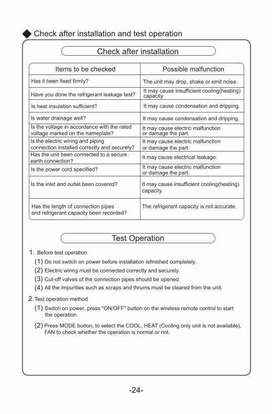
1.(1) Do not switch on power before installation isfinished completely.(2) Electric wiring must be connected correctly and securely.(3) Cut-off valves of the connection pipes should be opened.(4)
2.(1) Switch on power, press "ON/OFF" button on the wireless remote control to start the operation.
(2)
Check after installation and test operation
Check after installation
Items to be checked Possible malfunction
Has it been fixed firmly? The unit may drop, shake or emit noise.
Have you done the refrigerant leakage test? It may cause insufficient cooling(heating)capacity
Is heat insulation sufficient? It may cause condensation and dripping.
Is water drainage well? It may cause condensation and dripping.Is the voltage in accordance with the ratedvoltage marked on the nameplate?
It may cause electric malfunctionor damage the part.
Is the electric wiring and pipingconnection installed correctly and securely?
It may cause electric malfunctionor damage the part.
Has the unit been connected to a secureearth connection?
It may cause electrical leakage.
Is the power cord specified? It may cause electric malfunctionor damage the part.
Is the inlet and outlet been covered? It may cause insufficient cooling(heating)capacity.
Has the length of connection pipesand refrigerant capacity been recorded?
The refrigerant capacity is not accurate.
Test Operation
Before test operation
All the impurities such as scraps and thrums must be cleared from the unit.
Test operation method
Press MODE button, to select the COOL, HEAT (Cooling only unit is not available), FAN to check whether the operation is normal or not.
-24-
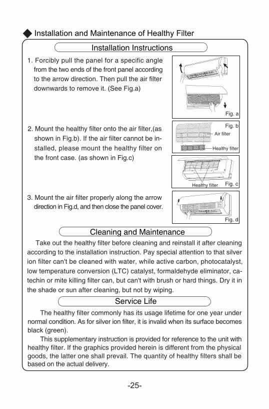
Fig. a
Installation Instructions1. Forcibly pull the panel for a specific angle
from the two ends of the front panel accordingto the arrow direction. Then pull the air filter
2. Mount the healthy filter onto the air filter,(asshown in Fig.b). If the air filter cannot be in-stalled, please mount the healthy filter on
3. Mount the air filter properly along the arrowdirection in Fig.d, and then close the panel cover.
ion filter can't be cleaned with water, while active carbon, photocatalyst, low temperature conversion (LTC) catalyst, formaldehyde eliminator, ca-
The healthy filter commonly has its usage lifetime for one year undernormal condition. As for silver ion filter, it is invalid when its surface becomes
according to the installation instruction. Pay special attention to that silverTake out the healthy filter before cleaning and reinstall it after cleaning
Installation and Maintenance of Healthy Filter
Cleaning and Maintenance
Service Life
●
Healthy filter
Air filter
Healthy filter
downwards to remove it. (See Fig.a)
the front case. (as shown in Fig.c)
Fig. b
Fig. c
Fig. d
techin or mite killing filter can, but can't with brush or hard things. Dry it inthe shade or sun after cleaning, but not by wiping.
black (green).
goods, the latter one shall prevail. The quantity of healthy filters shall bebased on the actual delivery.
This supplementary instruction is provided for reference to the unit withhealthy filter. If the graphics provided herein is different from the physical
-25-
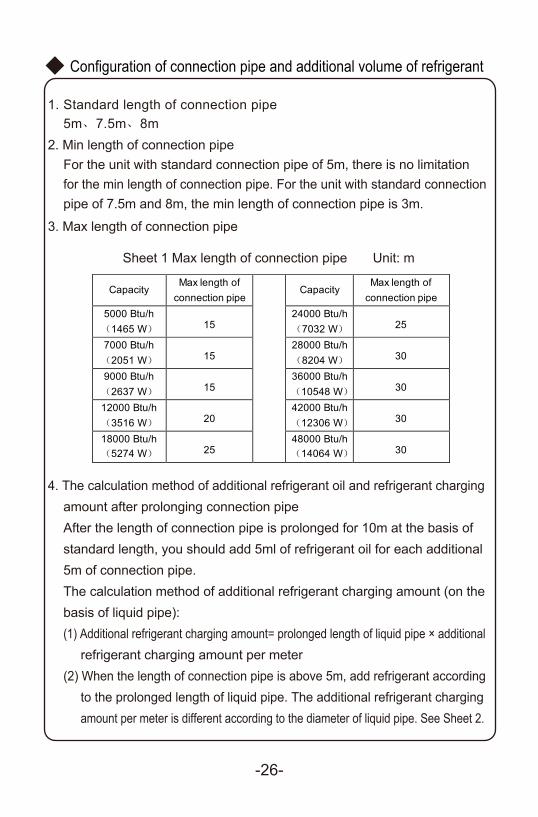
1. Standard length of connection pipe5m、7.5m、8m
2. Min length of connection pipeFor the unit with standard connection pipe of 5m, there is no limitationfor the min length of connection pipe. For the unit with standard connectionpipe of 7.5m and 8m, the min length of connection pipe is 3m.
3. Max length of connection pipe
4. The calculation method of additional refrigerant oil and refrigerant chargingamount after prolonging connection pipeAfter the length of connection pipe is prolonged for 10m at the basis ofstandard length, you should add 5ml of refrigerant oil for each additional5m of connection pipe.The calculation method of additional refrigerant charging amount (on the
(1) Additional refrigerant charging amount= prolonged length of liquid pipe × additionalrefrigerant charging amount per meter
(2) When the length of connection pipe is above 5m, add refrigerant accordingto the prolonged length of liquid pipe. The additional refrigerant chargingamount per meter is different according to the diameter of liquid pipe. See Sheet 2.
basis of liquid pipe):
Sheet 1 Max length of connection pipe Unit: m
Configuration of connection pipe and additional volume of refrigerant
-26-
Capacity Max length of
connection pipe Capacity
Max length of connection pipe
5000 Btu/h(1465 W) 15
24000 Btu/h(7032 W) 25
7000 Btu/h(2051 W) 15
28000 Btu/h(8204 W) 30
9000 Btu/h(2637 W) 15
36000 Btu/h(10548 W) 30
12000 Btu/h(3516 W) 20
42000 Btu/h(12306 W) 30
18000 Btu/h(5274 W) 25
48000 Btu/h(14064 W) 30
-27-
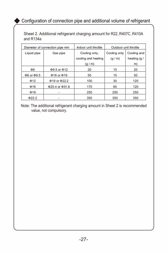
Sheet 2. Additional refrigerant charging amount for R22 R407C R410A and R134a
Note: The additional refrigerant charging amount in Sheet 2 is recommendedvalue, not compulsory.
Diameter of connection pipe mm Indoor unit throttle Outdoor unit throttle
Liquid pipe Gas pipe Cooling only,
cooling and heating
(g / m)
Cooling only
(g / m)
Cooling and
heating (g /
m)
Ф6 Ф9.5 or Ф12 20 15 20
Ф6 or Ф9.5 Ф16 or Ф19 50 15 50
Ф12 Ф19 or Ф22.2 100 30 120
Ф16 Ф25.4 or Ф31.8 170 60 120
Ф19 - 250 250 250
Ф22.2 - 350 350 350
Configuration of connection pipe and additional volume of refrigerant
Add: West Jinji Rd, Qianshan, Zhuhai, Guangdong, China, 519070Tel: (+86-756) 8522218 Fax: (+86-756) 8669426E-mail: [email protected] www.gree.com
GREE ELECTRIC APPLIANCES, INC. OF ZHUHAI
66162781
![COMMERCIAL AIR CONDITIONERS 2013 - Miraco CarrierMCAC-2012-32]R22... · COMMERCIAL AIR CONDITIONERS R22 Tropical Split Commercial A/C 50Hz 2013 Commercial Air Conditioner Business](https://img.dokumen.tips/doc/110x75/5acc2a417f8b9a93268c2cfe/commercial-air-conditioners-2013-miraco-mcac-2012-32r22commercial-air-conditioners.jpg)