Embed Size (px)
Citation preview

PORT OF LONDON AUTHORITY
TECHNICAL STANDARDS FOR COMMERCIAL VESSELS
ON THE TIDAL THAMES
(THAMES FREIGHT STANDARD)

1st Edition
ISBN Number: 978-0-900598-14-2
© Port of London Authority 2013
i 1
st Edition
1 June 2013
CONTENTS
1. FOREWORD ..................................................................................................... 1
2. DEFINITIONS .................................................................................................... 3
3. APPLICATION AND INTERPRETATION .......................................................... 8
3.1. Application ................................................................................................. 8
3.2. Areas of Operation ..................................................................................... 8
3.3. Licenses .................................................................................................... 8
3.4. Interpretation .............................................................................................. 8
3.5. The Right of Appeal ................................................................................... 8
3.6. Updating the Thames Freight Standard ..................................................... 9
3.7. Alternative Safety Standards ...................................................................... 9
3.8. Equivalent Standards ................................................................................. 9
3.9. Carriage of Additional Equipment ............................................................. 10
4. CONSTRUCTION AND STRUCTURAL STRENGTH...................................... 11
4.1. Structural Strength ................................................................................... 11
4.2. Construction Materials ............................................................................. 11
4.3. Wheelhouse Visibility ............................................................................... 12
4.4. Bulkheads ................................................................................................ 12
4.5. Weather Deck .......................................................................................... 13
4.6. Inflatable and Rigid Hull Inflatable Boats .................................................. 14
5. WEATHERTIGHT / WATERTIGHT INTEGRITY ............................................. 16
5.1. Hatchways and Hatches .......................................................................... 16
5.2. Doorways and Companionways Located Above the Weather Deck ......... 16
5.3. Skylights .................................................................................................. 17
5.4. Portlights and Windows ........................................................................... 17
5.5. Ventilators and Exhausts ......................................................................... 18
5.6. Air Pipes .................................................................................................. 18
5.7. Sea Inlets and Discharges ....................................................................... 18
5.8. Materials for Valves and Associated Piping ............................................. 19
5.9. General Equivalence ................................................................................ 19
6. WATER FREEING ARRANGEMENTS ........................................................... 20
7. MACHINERY ................................................................................................... 21
7.1. Machinery Installations ............................................................................ 21
7.2. Engine Exhaust System ........................................................................... 22

ii 1
st Edition
1 June 2013
7.3. Fuel Tanks, Oil Tanks, Pipes and Accessories ........................................ 22
7.4. Arrangements For Fuel, Lubricating Oil and Other Flammable Oils ......... 24
7.5. Oily-Water and Waste Oil ......................................................................... 25
7.6. Portable Equipment ................................................................................. 25
7.7. Petrol Engines ......................................................................................... 26
7.8. Stowage of Petrol .................................................................................... 27
8. ELECTRICAL ARRANGEMENTS ................................................................... 28
8.1. New Builds ............................................................................................... 28
8.2. All Existing Vessels .................................................................................. 28
8.3. Batteries .................................................................................................. 29
8.4. Earthing ................................................................................................... 31
8.5. Cables ..................................................................................................... 32
8.6. Location of Electrical Distribution / Switchboards ..................................... 33
8.7. Distribution Systems ................................................................................ 34
8.8. Switchgear Installations ........................................................................... 34
8.9. Switches and Protective Devices ............................................................. 35
8.10. Lighting Installations ................................................................................ 35
8.11. Alarm and Safety Systems For Mechanical Equipment ............................ 36
8.12. Connection to Shore or Other External Networks ..................................... 36
8.13. Power Supply to Other Vessels................................................................ 37
8.14. Generators and Motors ............................................................................ 37
8.15. Measuring and Monitoring Devices .......................................................... 37
8.16. Installation Fittings ................................................................................... 38
8.17. Electromagnetic Compatibility .................................................................. 38
8.18. Hazardous Spaces Other Than Enginerooms .......................................... 38
8.19. Protection Against Physical Contact, Intrusion of Solid Objects and the Ingress of Water ...................................................................................... 39
8.20. Maximum Permissible Voltages ............................................................... 40
8.21. Additional Requirements for Existing Vessels 24 metres and Over Load Line Length ............................................................................................. 41
9. STEERING GEAR, RUDDER AND PROPELLER SYSTEMS ......................... 42
9.1. General .................................................................................................... 42
9.2. Steering ................................................................................................... 42
9.3. Rudder System ........................................................................................ 42
9.4. Propeller System ..................................................................................... 42
10. BILGE PUMPING ............................................................................................ 43
10.1. Bilge Pumping and Drainage Systems ..................................................... 43

iii 1
st Edition
1 June 2013
10.2. Powered Vessels 24 metres and Over Load Line Length ......................... 43
10.3. Powered Vessels Less Than 24 metres Load Line Length. ...................... 44
10.4. Unpowered Vessels ................................................................................. 44
11. STABILITY ...................................................................................................... 45
11.1. General .................................................................................................... 45
11.2. Dry Cargo Vessels ................................................................................... 45
11.3. Vessels Fitted With a Lifting Device ......................................................... 45
11.4. Vessels Engaged in Towing ..................................................................... 46
11.5. Tankers .................................................................................................... 46
12. FREEBOARD, FREEBOARD MARKING AND DRAUGHT MARKS AND SCALES ........................................................................................................ 47
12.1. Safety Clearance ..................................................................................... 47
12.2. Freeboard ................................................................................................ 47
12.3. Draught Marks (Vessels 24 metres and over load line length or vessels carrying cargo in excess of 1000kg) ........................................................ 47
12.4. Freeboard Marks (Vessels greater than 13.7 metres LOA, but less than 24 metres load line length, or vessels carrying cargo less than 1000kg) . 50
12.5. Inflatable Boats and Rigid Inflatable Boats ............................................... 50
12.6. Draught Scales ........................................................................................ 51
13. LIFE-SAVING APPLIANCES .......................................................................... 52
13.1. General .................................................................................................... 52
13.2. Availability, Stowage and Maintenance of Life Saving Appliances ........... 52
13.3. Liferafts .................................................................................................... 53
13.4. Lifejackets ................................................................................................ 54
13.5. Lifebuoys ................................................................................................. 54
13.6. Thermal Protective Aids (TPAs) ............................................................... 55
13.7. General Alarm .......................................................................................... 55
13.8. Pyrotechnics ............................................................................................ 55
14. FIRE SAFETY ................................................................................................. 56
14.1. General .................................................................................................... 56
14.2. Vessels where the Total Installed Power Exceeds 750 kW ...................... 56
14.3. Insulation ................................................................................................. 57
14.4. Open Flame Gas Appliances ................................................................... 57
14.5. Fuel-Fired Heating, Cooking and Refrigerating Equipment ...................... 58
14.6. Use of Liquid Fuels - Oil-Fired Equipment ................................................ 59
14.7. Vaporising Oil Burner Stoves and Vaporising Oil Burner Heating Appliances ............................................................................................... 59

iv 1
st Edition
1 June 2013
14.8. Furnishing Materials ................................................................................. 60
14.9. Fire Detection .......................................................................................... 60
14.10. Means of Escape ..................................................................................... 61
15. FIRE APPLIANCES ........................................................................................ 62
15.1. General .................................................................................................... 62
15.2. Vessel Specific Requirements ................................................................. 62
15.3. Requirements for Portable Extinguishers ................................................. 63
15.4. Fixed Fire Extinguishing Systems ............................................................ 65
15.5. Additional Requirements for Tankers ....................................................... 65
16. RADIO COMMUNICATIONS EQUIPMENT ..................................................... 66
16.1. Radio Installation ..................................................................................... 66
16.2. Electrical Supply ...................................................................................... 66
16.3. Radio Personnel - Competency ............................................................... 66
16.4. Vessel Radio Licence .............................................................................. 66
17. NAVIGATION LIGHTS, SHAPES AND SOUND SIGNALS ............................. 67
18. NAVIGATIONAL EQUIPMENT ....................................................................... 70
18.1. Compass ................................................................................................. 70
18.2. Publications ............................................................................................. 70
19. OTHER EQUIPMENT FOR ALL VESSELS .................................................... 71
19.1. General .................................................................................................... 71
19.2. Radar Reflector ........................................................................................ 71
20. ANCHORS AND CABLES .............................................................................. 72
20.1. General .................................................................................................... 72
20.2. Requirements for Unusual Vessels .......................................................... 72
20.3. Anchoring Operations – All Vessels ......................................................... 72
20.4. Additional Requirements for Vessels Navigating Above Cherry Garden Pier.......................................................................................................... 73
20.5. Anchors & Cables for Vessels Less Than 24 metres Load Line Length ... 73
20.6. Bow Anchors for Vessels of 24 metres and Over Load Line Length ......... 74
20.7. Stern Anchors .......................................................................................... 75
20.8. Anchor Cables for Vessels 24 metres and Over Load Line Length .......... 76
21. ACCOMMODATION AND RECREATIONAL FACILITIES .............................. 77
21.1. General Requirements – All Vessels ........................................................ 77
21.2. Securing of Equipment ............................................................................. 77
21.3. Hand Holds and Grab-Rails ..................................................................... 77

v 1
st Edition
1 June 2013
21.4. Ventilation ................................................................................................ 77
21.5. Lighting .................................................................................................... 77
21.6. Domestic Hot Water Systems .................................................................. 78
21.7. Water Services ........................................................................................ 78
21.8. Galley ...................................................................................................... 78
21.9. Stowage Facilities for Personal Effects .................................................... 78
21.10. Vessels Used For Overnight Accommodation .......................................... 78
21.11. Excessive Noise and Vibration ................................................................. 78
21.12. Galley ...................................................................................................... 79
21.13. Toilet Facilities ......................................................................................... 79
21.14. New-Build Vessels - Additional Requirements For Accommodation ......... 79
22. SAFETY OF PERSONNEL ............................................................................. 83
22.1. General .................................................................................................... 83
22.2. Risk Assessment ..................................................................................... 83
22.3. Bulwarks, Guardrails and Handrails ......................................................... 83
22.4. Alternative Arrangements for Bulwarks, Handrails and Guardrails. .......... 84
22.5. Dimensions of working spaces ................................................................. 84
22.6. Protection Against Slips Trips and Falls ................................................... 84
22.7. Ventilation of Enclosed Workplaces ......................................................... 86
22.8. Natural and Artificial Light of Workplaces ................................................. 86
22.9. Variable Height Wheelhouses .................................................................. 86
22.10. Noise - New-Build Vessels ....................................................................... 87
22.11. General Safety ......................................................................................... 87
23. MEDICAL CARE ............................................................................................. 88
23.1. Medical Stores ......................................................................................... 88
24. TENDERS AND DINGHIES ............................................................................. 89
25. TOWING OPERATIONS ................................................................................. 90
25.1 Vessels Engaged in Commercial Towing Operations ............................... 90
25.2. Towing Arrangements .............................................................................. 90
25.3. Weathertight Integrity ............................................................................... 90
26. JACK – UP BARGES...................................................................................... 91
27. VESSELS FITTED WITH A DECK CRANE OR OTHER LIFTING DEVICE .... 92
28. VESSELS OPERATING IN PLANING MODE ................................................. 94
29. POLLUTION PREVENTION ............................................................................ 95
29.1. Sewage .................................................................................................... 95

vi 1
st Edition
1 June 2013
APPENDICES ......................................................................................................... 96
Technical Standard Reference in the Thames Freight Standard ............................. I
Fire extinguisher Standards .................................................................................. IV
Medical Stores for Vessels Certificated to Operate in Category C & D Waters ...... V

1 1
st Edition
1 June 2013
TECHNICAL STANDARDS
FOR COMMERCIAL VESSELS ON THE TIDAL THAMES
(THAMES FREIGHT STANDARD)
1. FOREWORD 1.1. The Thames Freight Standard (the Standard) applies to all non-passenger,
commercial vessels that wish to operate in Categorised Waters, which are under the jurisdiction of the Port of London Authority (PLA); unless such vessels are already certificated to a higher or seagoing standard or are exempt by the provisions of Section 124 of the Port of London Act 1968 (as amended) (the Act).
1.2. The Merchant Shipping Act 1995 also applies in respect of vessels operating under
the jurisdiction of the Port of London Authority. However, the Maritime and Coastguard Agency (MCA) has no powers to survey or certificate non-passenger vessels that do not go to sea, and operate on Inland Waterways (i.e. Categorised Waters). MCA Surveyors do however have powers, under the Merchant Shipping Act, to inspect any vessel, and to prevent it from operating if they consider it does not satisfy applicable safety requirements or otherwise presents a significant safety risk to its crew, other vessels or the environment. Under the UK ship classification system, non-passenger vessels that do not go to sea are Class IX (A) or, if tankers, Class IX (A) (T). They are subject to statutory safety requirements for the carriage of life saving appliances and fire fighting equipment. However, vessels that satisfy, and are certificated under, the Thames Freight Standard are exempted from the Class IX (A) and IX (A) (T) requirements.
1.3. The Standard sets out the minimum technical requirements for non passenger
commercial vessels in terms of construction, machinery, freeboard, communications, navigation, life saving appliances, fire fighting and fire prevention; crew accommodation and the protection of personnel.

2 1
st Edition
1 June 2013
1.4. Vessels that hold certification in compliance with the following standards are not required to additionally meet the requirements of this Standard:
- the MCA Code of Practice for the Safety of Small Commercial Vessels and Pilot
Boats; or - The Rhine Inspection Regulations; or the - Community Inland Navigation Certificate issued under the Directive 2006/87 (as
amended), (the Technical Requirements for Inland Waterway Vessels). Note: Vessels complying with the Rhine Inspection Regulations or the Community Inland Navigation Certificate need to be certificated for the appropriate category of Inland Waterway
(i.e. Zones 1 & 2 equates to UK Categories D & C).
1.5. Vessels required to be licensed by the PLA which carry up to 12 passengers and no freight or cargo will be required to comply with the Inland Waters Small Passenger Boat Code.
1.6. In addition to meeting the requirements of the Thames Freight Standard, the owner of a vessel licensed by the PLA is also required to comply with the provisions of the PLA’s Code of Practice for the Management and Operation of Inland Waterways Commercial Vessels on the Thames. This Code provides for the establishment and maintenance of a vessel safety management system, which includes operational responsibilities, personnel and training, on board procedures, vessel maintenance, reporting incidents, specialist operations and emergency management; and which complements the technical standards required by this Standard. The Code of Practice also sets generic minimum manning levels and identifies the associated relevant crew competency requirements.
1.7. The vessel owner is responsible for ensuring that the vessel complies with all
relevant licensing and certification requirements that may be necessary by virtue of the vessel’s type or area of operation, in addition of the PLA’s requirements under this Standard.
1.8. Legislation and Guidance – Any reference in this Standard to international or national legislation, published guidance, Codes of Practice or other information also applies to any subsequent, relevant legislation, guidance codes or information, replacing or updating that originally referenced.
1 June 2013

3 1
st Edition
1 June 2013
2. DEFINITIONS
a) ‘accommodation space’ means any space, enclosed on all sides by solid divisions provided for the use of persons on board;
b) ‘acceptable’ means acceptable to the PLA, unless otherwise specified in the Standard;
c) “annual and / or biennial inspection” means a general or partial examination of the
vessel, its machinery, fittings and equipment, as far as can readily be seen, to ascertain that it has been satisfactorily maintained as required by the Standard, and that the arrangements, fittings and equipment provided are as documented in the Compliance Inspection and Declaration report form IWFV2.The hull, shell fittings, external steering and propulsion components of the vessel should be examined out of the water at intervals not exceeding 5 years. The PLA may stipulate a lesser interval in consideration of hull construction material, age, type and service of the vessel;
d) ‘approved classification society’ means a classification society approved by the
Maritime and Coastguard Agency; e) ‘barge’ includes dumb vessels, including but not limited to; barges, lighters, collar
and mooring barges, crane and engineering barges, pontoons, oil storage/processing barges, dredgers and modular units, but excludes any power-driven vessels;
f) ‘boiler room’ means a space housing a fuel-operated installation designed to produce
steam or heat a thermal fluid; g) ’breadth (B)’ means the greatest width of the vessel’s hull in metres, measured to the
outside of the hull plating (excluding paddle wheels, fixed fenders etc.); h) ‘bulkhead’ means a division of a given height, usually vertical, that separates areas of
the vessel and restricted by the vessel’s bottom, side plating or other bulkheads; i) ‘bulkhead deck’ means the deck to which the required watertight bulkheads join and
from which the freeboard is measured; j) ’Categorised Waters’ means waters designated in the Merchant Shipping
(Categorisation of Waters) Regulations 1992, (SI 1992 No. 2356), as amended, and Merchant Shipping Notice MSN 1827(M) – Categorisation of Waters;
k) ‘crew’ means a person employed or engaged in any capacity on-board a vessel, on
the business of the vessel: l) ’compliance inspection’ means an examination of the vessel, its machinery, fittings
and equipment, by an authorised person, to ascertain that the vessel’s structure, machinery, fittings and equipment comply with the requirements of the Standard. Part of the examination should be conducted when the vessel is out of the water. Part of the examination should be conducted when the vessel is in the water;
m) ‘depth (D)’ means the smallest vertical distance in metres between the inside of the
bottom of the hull bottom plating or keel and the lowest point of the deck at side;

4 1
st Edition
1 June 2013
n) ‘draught (T)’ means the vertical distance in metres between the deepest part of the hull bottom plating or keel and the plane of maximum draught;
o) ‘drive unit’ means the steering gear drive, between the power source and the steering
gear; p) ‘engine space’ means those spaces and trunks to such spaces which contain:
i) internal combustion machinery used for main propulsion; or
ii) any oil-fired boiler or oil fuel unit designed to produce steam or a thermal fluid with a pressure greater than 0.18N/mm2. Oil fuel unit includes any equipment used for the preparation and delivery of oil fuel, heated or not, to boilers (including inert gas generators) and engines (including gas turbines) at a pressure of more than 0.18 N/mm2; or
iii) inert gas generators, incinerators greater than 75kW, waste disposal units; or
iv) oil fuel pumps with pressure greater than 0.98 N/mm2.
q) ‘existing vessel’ means a vessel that was licensed by the PLA or other navigation
authority to a standard acceptable to the PLA, and holding a valid licence or certificate, before the date this Standard comes into force;
Note: Vessels that have previously been licensed by the PLA, but which are currently laid up, will be treated as existing vessels provided they are re-licensed within 2 years from the date this Standard comes into force.
r) ‘fire-resistance’ means the property of structural components or devices as certified
by the test procedure in Annex I, Part 3, of the International Code for the Application of Fire Text Procedures adopted under Resolution MSC.61(67) by the Marine Safety Committee of the IMO;
s) ‘flame-retardant’ means material which does not readily catch fire or whose surface
at least restricts the spread of flames pursuant to the test procedure in Annex 1, Parts 5 (Surface flammability test), 6 (Test for the deck coverings), 7 (Test for hanging textiles and plastics), 8 (Test for upholstered furniture) and 9 (Test for components of bedding) of the International Code for the Application of Fire Test Procedures adopted under Resolution MSC.61(67) by the Marine Safety Committee of the IMO;
t) ‘fore perpendicular’ means an imaginary vertical line where the bow of the vessel
meets the plane of maximum draught; u) ‘freeboard (F)’ means the distance between the plane of maximum draught and the
parallel plane through the lowest point of the deck-side or, where there is no deck-side, the lowest point of the top of the hull side;
v) ‘gastight’ means a component or device built or fitted so as to prevent the passage of
gas or vapour; w) ‘hand-hydraulic drive’ means a form of steering with manual hydraulic transmission; x) ‘hand steering’ means a system where a manual operation of a steering wheel or
tiller operates the rudder by mechanical linkage without any additional power supply;

5 1
st Edition
1 June 2013
y) ‘high holding power anchor’ means an anchor that can be shown to have holding powers of at least twice those of a standard stockless anchor of the same mass;
z) ‘hold’ means the part of the vessel, with a bulkhead at either end, intended to contain
the cargo, either open topped or closed by means of hatches; aa) ‘inland waterways vessel’ means a vessel intended solely or mainly for use on
Categorised Waters;
bb) ‘inflatable boat’ means a vessel fitted with an inflatable collar, that does not have a rigid hull form;
cc) ‘length (L)’ means the length from the foreside of the foremost fixed permanent
structure to the aft side of the aftermost fixed permanent structure of the vessel. For inflatable boats or rigid inflatable boats or boats fitted with a buoyant collar, length should be taken from the foremost part of tube or collar, to the aft most part of the tube or collar;
dd) ‘length overall’ means the maximum length of a vessel, including overhanging
structures, cargo or equipment, and if a tug and tow, the combination of the tug and the object(s) towed excluding the length of the towing medium.
ee) ‘load line length’ in relation to a vessel means the greater of the following distances:
i) 96% of the total length on a waterline at 85% of the least moulded depth measured from the top of the keel, or
ii) the length from the fore-side of the stem to the axis of the rudder stock on that waterline.
Where the stem contour is concave above the waterline at 85% of the least moulded depth, both the forward terminal of the total length and the fore-side of the stem respectively shall be taken at the vertical projection to that waterline of the aftermost point of the stem contour (above that waterline). In vessels designed with a rake of keel the waterline on which this length is measured shall be parallel to the designed waterline;
ff) ‘main engine room’ means the space containing the main propulsion machinery;

6 1
st Edition
1 June 2013
gg) “Marine Guidance Note” (MGN) means a Note described as such and issued by the MCA, and reference to a specific Marine Guidance Note includes reference to any Marine Guidance Note amending or replacing that Note which is considered by the Secretary of State to be relevant from time to time;
hh) “Marine Information Note” (MIN) means a Note described as such and issued by the
MCA, and reference to a specific Merchant Shipping Notice includes reference to any Marine Information Note amending or replacing that Note which is considered by the Secretary of State to be relevant from time to time;
ii) “Merchant Shipping Notice” (MSN) means a Notice described as such and issued by
the MCA, and reference to a specific Merchant Shipping Notice includes reference to any Merchant Shipping Notice amending or replacing that Notice which is considered by the Secretary of State to be relevant from time to time;
jj) ‘new-build vessel’ means any vessel for which the keel was laid after the date on which this Standard comes into force;
kk) ‘owner’: means the owner of the vessel or any other organisation or person such as
the manager, or the bareboat charterer, who has assumed responsibility for operation of the vessel from the vessel owner and who, on assuming such responsibility, has agreed to take over all duties and responsibilities imposed by the Standard;
ll) ‘plane of maximum draught’ means the plane corresponding to the maximum draught
at which the vessel is permitted to operate; mm) ‘power source’ means the power supply for the steering gear drive and the control
system; either from batteries, internal combustion engine or the vessel’s electrical system;
nn) ‘pusher-tug’ means a vessel specially built or adapted to push a push-tow formation,
which may or may not be composite unit; oo) ‘potable water’ means water pure enough to be consumed or used with low risk of
immediate or long term harm pp) ‘rate-of-turn regulator’ means equipment, which automatically monitors and maintains
a given rate-of-turn of the vessel in accordance with the values entered into it; qq) ‘renewal inspection’ means an examination undertaken at the renewal of the vessel’s
licence, which is similar to the compliance inspection; rr) ‘rudder’ means the rudder blade or blades and includes all rudder shafts, rudder
quadrants and all components connecting to the steering gear; ss) ‘safety clearance’ means the distance between the plane of maximum draught and a
parallel plane passing through the lowest point at which the vessel is no longer deemed to be watertight;
tt) ‘Safety Management System’ means a structured and documented system relating to
the safe and efficient operation of the vessel, enabling company personnel to effectively implement the owner’s safety and environmental protection policy;
uu) ‘Scantling draught’ means the vessel’s maximum design draught;

7 1
st Edition
1 June 2013
vv) ‘sea-going ship’ means a vessel certificated for deep sea or coastal use; ww) ‘self-propelled vessel’ means a vessel intended to carry cargo and built to navigate
independently under its own power; xx) ‘ship-mounted barge’ means a non-powered barge or a push barge built to be carried
in or aboard a sea-going ship and to navigate inland waterways; yy) ‘steering apparatus’ means the part of the steering system which produces the
movement of the rudder; zz) ‘steering control’ means the components and circuitry to control power driven
steering drive unit(s); aaa) ‘steering gear ’ means the equipment, including powered drive unit that applies
torque to the rudder stock necessary for the effective movement of the rudder, for the purpose of steering the vessel;
bbb) ‘steering system’ means all the equipment required to steer the vessel so as to
comply with the manoeuvrability requirements of Section 9.1; ccc) ‘superstructure’ means a watertight permanent structure with rigid boundaries joined
to the deck in a permanent and watertight manner; ddd) ‘tank’ means a tank permanently part of the vessel; the boundaries of the tank being
either the hull itself or a separate ‘skin’; eee) ‘transverse bulkhead’ means a bulkhead extending from the side plating on one side
to the side plating on the other; fff) ‘tug’ means a vessel propelled by mechanical power and used for towing or pushing
another vessel or a raft or float of timber;
ggg) ‘type 1 vessels’ include but is not limited workboats (not engaged in towing), and all dumb barges;
hhh) ‘type 2 vessels’ include, but is not limited to motor barges, tank barges, oil storage
barges, tugs, ship towage tugs, all powered vessels 24 metres and over load line length, and all vessels fitted with a lifting device;
iii) ‘vessel’ means every description of vessel however propelled or moved and includes
anything constructed or used to carry persons or goods by water: jjj) ‘watertight’ means a structural component or device fitted out in such a manner as to
prevent the passage of water in either direction under any sea condition; kkk) ‘weather deck’ means the main deck which is exposed to the elements lll) ‘weathertight’ means being capable of preventing the admission of a significant
quantity of water into the vessel when subjected to a standard hose test; mmm) ‘wheelhouse’ means the space containing the controls and instruments necessary for
manoeuvring and navigating the vessel.

8 1
st Edition
1 June 2013
3. APPLICATION AND INTERPRETATION 3.1. Application
This Standard applies to all commercial vessels navigating, working or mooring 3.1.1.within the Port of London Authority vessel licensing area, which are subject to the licensing requirements of the Port of London Act 1968 (as amended), with the exception of:
a) passenger boats licensed by the PLA to carry 12 or less passengers; and
b) rowing boats licensed by the PLA.
It is the responsibility of the owner to ensure that a vessel is: 3.1.2.
a) built, equipped, surveyed, licensed, maintained and operated in accordance with the relevant provisions of this Standard;
b) subjected to annual or biennial inspections (whichever is appropriate), in accordance with this Standard.
A vessel to which this Standard applies, but which exceeds the speed/displacement 3.1.3.
ratio as defined within the ‘The Merchant Shipping (High Speed Craft) Regulations 2004, (SI 2004 No. 302), as amended, need not be considered under the High Speed Craft Regulations, if licensed to the requirements of this Standard.
3.2. Areas of Operation
A vessel meeting the requirements of this Standard will be licensed to operate within 3.2.1.Category C and/or Category D Waters, within the vessel licensing area.
Restrictions may be placed on the area of operation of a vessel. Any such restrictions 3.2.2.
will be recorded on the vessel’s licence. 3.3. Licenses
To be issued with a licence for a particular area of operation, a vessel must comply 3.3.1.with all of the relevant requirements of the Standard for that operating area, to the satisfaction of the PLA.
A licence will be valid for not more than five years. 3.3.2.
3.4. Interpretation Where a question of the application of the Standard or an interpretation of a part of
the Standard arises, the owner concerned should seek clarification from the PLA. 3.5. The Right of Appeal
Appeals against any decision resulting from a vessel inspection should be made in 3.5.1.writing to the PLA Marine Surveyor clearly stating the grounds of the appeal; the application of appeal should be made within twenty eight days of the inspection. An appeal meeting will be arranged to take place within 10 working days of the submission of the formal appeal. The appeal hearing will be chaired by the Port of London Authority, Harbour Master, Safety Management Systems with the support of

9 1
st Edition
1 June 2013
two suitably qualified persons from either the PLA or MCA. The Marine Surveyor or Deputy Marine Surveyor may also attend to present the case behind the initial decision. Additional members may be selected based upon the nature of the appeal and the required disciplines.
The complainant should ensure that they attend the appeals hearing at the specified 3.5.2.time mutually agreed by both parties. If the complainant is unable to attend at the agreed time and date, they shall inform the Marine Surveyor as soon as possible. If the complainant fails to attend without explanation, or if it appears that a complainant has not made sufficient attempts to attend, the hearing will take place in their absence.
The appeal hearing will consider the grounds that have been put forward and assess 3.5.3.whether the conclusion reached during the inspection was appropriate. The appeal is a consideration of the specific areas with which a complainant is dissatisfied in relation to the original decision. The Chairman of the appeals hearing may therefore confine discussions to the specific areas of the inspection through which the grievance has occurred.
Following the appeal hearing, the complainant will be informed of the outcome within 3.5.4.five working days. If the complainant remains dissatisfied, the matter may be referred to the MCA. If the MCA were present at the appeals hearing and concur with the original decision, the decision approved at the hearing will be final.
3.6. Updating the Thames Freight Standard
In addition to the guidance on application and interpretation of the Standard, the 3.6.1.requirements of the Standard will be regularly reviewed by the PLA. Amendments will be promulgated and a formal review of the Standard will be conducted no later than five years from the date of publication, and thereafter at intervals not exceeding five years.
When new standards are developed and issued by the British Standards Institution 3.6.2.
(BSI), European Committee for Standardization, International Maritime Organization (IMO), International Organisation for Standardisation (ISO) or any other international body, which impact upon the requirements of the Thames Freight Standard, any necessary amendments will be incorporated as soon as possible. In the interim period, draft standards may be applied where the MCA have accepted them as an equivalent standard.
3.7. Alternative Safety Standards
When the owner of a vessel considers that full application of the Standard would be inappropriate, the owner may submit a request to the PLA, to consider alternative safety standards.
3.8. Equivalent Standards
Where the Standard requires that a particular piece of equipment or machinery 3.8.1.should be provided or carried in a vessel or that a particular provision should be made, to a specified standard, the PLA may permit equivalent standards for that equipment, machinery or specific provision. In order to recognise the alternative arrangements the PLA must be satisfied by either technical standards, trials, documentary evidence or otherwise that the alternative is at least as effective as that required by this Standard.

10 1
st Edition
1 June 2013
The results of verification tests carried out by bodies and laboratories of other 3.8.2.
Member States of the European Economic Area (EEA) Agreement, and Turkey, offering suitable and satisfactory guarantees of technical and professional competence and independence should be accepted.
3.9. Carriage of Additional Equipment Equipment additional to the requirements of this Standard, which is expected to be
relied on in situations affecting safety or pollution prevention, must be in full operating condition. If such equipment is inoperative and is in excess of the equipment required by this Standard it should either be repaired, removed or if removal is not practicable clearly marked as inoperative and secured1.
1 Further guidance can be found in MGN 79 (M+F) “Safety Equipment and Pollution Prevention Equipment Carried in
Excess of Statutory Requirements”.

11 1
st Edition
1 June 2013
4. CONSTRUCTION AND STRUCTURAL STRENGTH 4.1. Structural Strength The design of the hull structure shall provide sufficient strength and service life for
the safe operation of a vessel, at its service draught and maximum service speed, to withstand the conditions it is likely to encounter within Category C and/or Category D waters.
4.2. Construction Materials
A vessel may be constructed of wood; fibre reinforced plastic (FRP), aluminium alloy, 4.2.1.steel or combinations of such materials. The hull shall be sufficiently strong to withstand all of the stresses to which it is normally subjected:
a) in the case of new-build vessels or major conversions affecting a vessel’s strength, adequate strength shall be demonstrated by presenting proof of design and calculation. Where a classification certificate is issued by an International Association of Classification Society (IACS) which is recognised by the PLA, such certificate should be submitted to the PLA as proof of design and strength.
b) Vessels built in steel shall be designed with a diminution limit of 25%. Where greater limits are applied, they will be discussed and agreed with the PLA, and the minimum permissible thicknesses are to be clearly marked on the vessels documents.
c) Greater diminution, up to 30%, will be considered acceptable at localised points, to the satisfaction of the PLA.
d) Where a vessel is built and maintained to an approved classification societies rules and regulations, the classification society diminution limits shall be applied.
e) For unpowered vessels plates shall be renewed if bottom, bilge or side plates are below the permissible value laid down in this Standard. Alternatively, on a case by case basis over-plating (“doublers”) may be used in accordance with approved methods as required by the PLA. The use of over-plating is only permitted as sacrificial wear/rubbing strips or as means for a temporary repair.
f) Collar barges and vessels with existing over-plates will be reviewed on a case by case basis.
Note: All diminution limits are only applicable to steel vessels.
New build Vessels will have demonstrated that they meet the criteria of Section 4 if 4.2.2.
they are surveyed and certificated to appropriate class rules (e.g. BV Rules for the Classification of Inland Navigation Vessels or Lloyds Rules for Special Ships) by a Class Society recognised by the PLA, in accordance with Directive 2006/87/EC (as amended). Alternatively a new build vessel may demonstrate that it meets the requirements of Section 4 if it is so designed and built, based on an existing vessel with at least five years safe operating history in an equivalent category of inland waters.
Existing Vessels may demonstrate that they meet the criteria of Section 4 if, after 4.2.3.
satisfactory examination by the PLA, they comply with one of the following:
a) A vessel that has been surveyed and certificated to appropriate class rules (e.g. BV Rules for the Classification of Inland Navigation Vessels or Lloyds Rules for

12 1
st Edition
1 June 2013
Special Ships) by a Class Society recognised by the PLA, inline with the requirements of MSN 1672; or
b) A vessel that has previously been in Class (within 2 years and 3 months of the expiry of the last examination of the vessel) that is inspected and maintained to the requirements set out in this Standard; or
c) An owner which can provide evidence, which may be the provision of appropriate certification, of a minimum of 5 years safe operating history by the vessel, in an equivalent category of inland waters, that has been inspected and maintained to the satisfaction of the PLA; or .
d) A vessel that complies with the construction and machinery standards applicable under the Code of Practice for Small Commercial Vessels and Pilot Boats.
Note: Where a minimum of 5 years safe history cannot be demonstrated then plans and full
supporting calculations should be submitted as set out in MGN 322.
4.3. Wheelhouse Visibility The horizontal and vertical arcs of visibility from the wheelhouse of all vessels must
provide sufficient visibility to maintain a proper lookout as required by the International Regulations for the Prevention of Collisions at Sea.
4.4. Bulkheads
New-build Decked Vessels 4.4.1.Bulkheads rising up to the deck shall be installed at the following points:
a) A collision bulkhead at a suitable distance from the bow in such a way that the buoyancy of the laden vessel is ensured, with a residual safety clearance of 100mm if water enters the watertight compartment ahead of the collision bulkhead. As a general rule, this requirement shall be considered to have been met if the collision bulkhead has been installed at a distance of between 0.04L and 0.04L + 2m measured from the fore perpendicular line in the plane of maximum draught. If this distance exceeds 0.04L + 2m this requirement shall be proved by calculation.
b) An aft-peak bulkhead at a suitable distance from the stern where the vessel is 24 metres and over load line length.
Existing Vessels 24 metres and Over Load Line Length 4.4.2.
Bulkheads rising up to the deck or, where there is no deck, up to the gunwale, shall be installed at the following points:
a) A collision bulkhead at a suitable distance from the bow.
b) An aft-peak bulkhead at a suitable distance from the stern.
Existing Vessels less than 24 metres Load Line Length 4.4.3.
All existing vessels less than 24 metres should meet the requirements of Section 4.4.2 as far as practicable.
Vessels which can not comply with the requirements of Sections 4.4.1, 4.4.2 or 4.4.3 4.4.4.will be assessed by the PLA on a case by case basis.
13 1
st Edition
1 June 2013
For all vessels the following applies: 4.4.5.
a) No accommodation or equipment needed for vessel safety or operation may be located ahead of the plane of the collision bulkhead. This requirement shall not apply to anchor gear.2
b) The accommodation, engine spaces, and the workspaces forming part of these, shall be separated from the holds by watertight transverse bulkheads that extend up to the weather deck.
c) The accommodation shall be separated from the engine spaces, and from the holds, by gas tight divisions and shall be directly accessible from the weather deck. If this access has not been provided an emergency exit shall also lead directly to the weather deck3.
d) The bulkheads specified in Sections 4.4.1 to 4.4.3 and the separation of areas specified in Section 4.4.4 shall not contain any openings. However, doors in the aft peak bulkhead and penetrations, in particular for shafts and pipework, shall be permitted where they are so designed that the effectiveness of those bulkheads and of the separation of areas is not impaired3. The doors in the aft peak bulkhead shall bear the following legible instruction on both sides: “Door shall be closed immediately after use”.
4.5. Weather Deck Where a vessel is fitted with a watertight weather deck, it should extend from stem to 4.5.1.
stern and have a positive freeboard throughout, under any condition of loading. (Minimum requirements for freeboard are given in Section 12).
A weather deck may be stepped, recessed or raised provided the stepped, recessed 4.5.2.
or raised portion is of watertight construction.
Recesses (Vessels Less Than 24 metres Load Line Length) 4.5.3.For general water-freeing arrangements, see Section 6 and for freeboard requirements, see Section 12.
4.5.3.1. For motor vessels, a recess in the weather deck complying with Section 4.5.1, should
be of watertight construction and have means of drainage capable of efficient operation when the vessel is heeled to an angle of 10 degrees. Such drainage is to have an effective area, excluding grills and baffles, of at least 200mm2 for each cubic metre of volume of recess below the weather deck.
4.5.3.2. Alternative arrangements for the size and drainage of a recess may be accepted, provided it can be demonstrated that, with the vessel upright and at its deepest draught, the recess drains from a swamped condition within 3 minutes; or the cockpit or recess should comply with ISO 11812 (Small Craft – Watertight and Quick Drainage Cockpits) for the relevant design category.
4.5.3.3. If a recess is provided with a locker, which gives direct access to the interior of the
hull, the locker should be permanently attached to the vessel structure and fitted with efficient locking devices to secure the covers in the closed position.
2 Safety equipment includes Life Saving Apparatus and Firefighting Equipment but not bow thrusters.
3 This will be assessed on a case by case basis for existing vessels with a 5 year history of safe operational use.

14 1
st Edition
1 June 2013
4.6. Inflatable and Rigid Hull Inflatable Boats An inflatable or rigid inflatable boat over 8m length overall, which is not a tender 4.6.1.
operating from a vessel should be of a design and construction, which would meet the requirements of Chapter III of the 1974 SOLAS Convention, as amended; and the parts of the Annex to IMO Resolution MSC.48 (66) – International Life-Saving Appliance Code, as amended, and MSC.81 (70) – Testing and Evaluation of Life–Saving Appliances, as amended – which are appropriate to the type of boat.
An inflatable or rigid inflatable boat, of less than 8m in length, which is intended to 4.6.2.
operate as an independent vessel should meet the minimum design standard of ISO 6185 Part 2 or 3 as appropriate to the engine size. Inflatable boats or rigid inflatable boats meeting the requirements of ISO 6185 Part 1 are not suitable for operation under this Standard.
When the manufacture of such boats is covered by an acceptable quality system and 4.6.3.
boats are built in batches to a standard design, prototype tests on one boat may be accepted for the boat of the same design category.
Construction Materials for Rigid Inflatable Boats 4.6.4.
4.6.4.1. For boats complying with Section 4.6, construction materials should satisfy the requirements ISO 15372:2000 Ships and marine technology. Inflatable rescue boats. Coated fabrics for inflatable chambers), except that fire–retarding characteristics are not required for the hull material.
4.6.4.2. A new boat of a type certified as a rescue boat under the Merchant Shipping (Marine Equipment) Regulations 1999 (SI 1999 No. 1957), as amended, or provided with a letter of compliance for use as a fast rescue boat for offshore stand-by vessels, or any equivalent certification or compliance, should be accepted as complying with the construction requirements of this Standard.
4.6.4.3. A new boat which is not built in accordance with Section 4.6 may be specially
considered, provided that full information (including calculations, drawings, details of materials and construction) is presented to, and accepted by the PLA.
4.6.4.4. A permanent shelter provided for the protection of persons on-board should be of such construction adequate for the intended purpose and the intended area of operation.
Testing 4.6.5.
4.6.5.1. In addition to the survey regime detailed within this Standard, the following air tightness test should be undertaken annually by a competent person;
a) Inflate each compartment of the boat individually to 120% of the safe working pressure.
b) Check the integrity of tubes and seams for each compartment with soapy water and, in the case of a rigid inflatable boat, the integrity of the joints between the tubes and the hull.
c) Check that after 30 minutes the pressure is still at 120%.
d) Inflate all compartments to the safe working pressure, and record the ambient temperature. After 24 hours in this condition, pressures should be re-checked and the ambient temperature retaken and then check that the pressure is not less than 100% of working pressure.
e) A declaration should be sent to the PLA on completion of the test.

15 1
st Edition
1 June 2013
4.6.5.2. At the vessel’s renewal inspection, testing shall be conducted to the satisfaction of
the PLA by a competent person in accordance with the manufacturer’s recommendations.

16 1
st Edition
1 June 2013
5. WEATHERTIGHT / WATERTIGHT INTEGRITY A vessel should be designed and constructed in a manner which will prevent the
ready ingress of water and in particular comply with the following requirements. Note: For vessels less than 24 metres load line length, ISO 12215 may be considered
acceptable for strength and water-tightness purposes only.
5.1. Hatchways and Hatches A hatchway which gives access to spaces below the weather deck should be of 5.1.1.
efficient construction and be provided with efficient means of weathertight closure.
A cover to a hatchway should be hinged, sliding, or permanently secured by other 5.1.2.equivalent means to the structure of the vessel and be provided with sufficient locking devices to enable it to be positively secured in the closed position.
A hatchway with a hinged cover which is located in the forward half of the vessel 5.1.3.should generally have the hinges fitted to the forward side of the hatch, to protect the opening from boarding seas, except where it is not possible to do so, due to the shape of the hatch or the moulding it is in. A hatch with the hinges on the after side of the hatch should be secured closed when underway. This is not intended to apply to small technical spaces drained directly overboard, e.g. anchor lockers.
Hatches which are used for escape purposes should be capable of being opened 5.1.4.from both sides.
Hatches in recessed or stepped decks of vessels described in Section 4.5.2, that 5.1.5.provide access to sea inlet valves, should have access openings at least 300mm above the minimum freeboard to deck (see Section 12), or the sea inlet valves fitted with remote closing devices.
Hatchways Which Are Open When Underway 5.1.6.In general, hatches should be kept secured closed when underway. However, a hatch which is to be open when underway for lengthy periods should be:
a) kept as small as practicable, but never more than 1m² in plane area at the top of the coaming;
b) located on the centre line of the vessel or as close thereto as practicable;
c) fitted such that the access opening is at least 300mm above the top of the adjacent weather deck at side.
5.2. Doorways and Companionways Located Above the Weather Deck 5.2.1. A doorway located above the weather deck which gives access to spaces below
should be provided with a weathertight door. The door should be of efficient construction, permanently attached to the bulkhead, not open inwards, and sized such that the door overlaps the clear opening on all sides, and has efficient means of closure which can be operated from either side.
5.2.2. A doorway should be located as close as practicable to the centre line of the vessel. However, if hinged and located in the side of a housing, the door should be hinged on the forward edge. Doors using articulated systems should be specially considered, in order to provide an equivalent arrangement.

17 1
st Edition
1 June 2013
5.2.3. A doorway which is either forward or side facing should be provided with a coaming,
the top of which is at least 300mm above the weather deck. A coaming may be portable provided it can be permanently secured to the structure of the vessel and can be locked in position whilst underway.
5.3. Skylights 5.3.1. A skylight should be of efficient weathertight construction and should be located on
the centre line of the vessel, or as near thereto as practicable, unless it is required to provide a means of escape from a compartment below deck.
5.3.2. When a skylight is an opening type it should be provided with efficient means
whereby it can be secured in the closed position. 5.3.3. A skylight which is provided as a means of escape should be capable of being
opened from both sides. 5.4. Portlights and Windows 5.4.1. A portlight or window to a space below the weather deck or in a step, recess, raised
deck structure, deckhouse or superstructure protecting openings leading below the weather deck should be of efficient construction, which provides weathertight integrity for the intended area of operation of the vessel.
5.4.2. A portlight or window should not be fitted in the main hull below the weather deck,
unless the glazing material and its method of fixing in the frame are equivalent in strength, with regard to design pressure, to that required for the structure in which it is fitted.
5.4.3. Portlights fitted in the hull of the vessel below the level of the weather deck should be
either non-opening or of a non-readily opening type, have a glazed diameter of not more than 250mm, or equivalent area, and be in accordance with a standard recognised by the PLA. Portlights of the non-readily opening type must be secured closed when the vessel is underway.
5.4.4. Portlights, windows and their frames should meet the appropriate marine standards
defined in equivalent British, European, National or International Standards or Classification Society Rules.
5.4.5. A window fitted in the main hull below the weather deck should meet the
requirements of Sections 5.4.1, 5.4.2, 5.4.3 & 5.4.4 , or be provided with a blank meeting the requirements of ISO 12216 - (Small Craft, Windows, Portlights, Hatches, Deadlights and Doors - Strength and Watertightness Requirements.)
Such a ‘blank’ is not required for a non opening portlight which satisfies the requirements of Section 5.4.2
5.4.6. For the wheelhouse; polarised or tinted glass should not be used in windows provided for navigational visibility (although approved portable tinted screens may be provided for nominated windows).

18 1
st Edition
1 June 2013
5.5. Ventilators and Exhausts 5.5.1. A ventilator should be of efficient construction and, where situated on the weather
deck and not complying with Section 5.5.3, should be provided with a readily available means of weathertight closure. Consideration should be given to requirements of Section 14 - Fire Safety.
5.5.2. A ventilator should be kept as far inboard as practicable and the height above the
deck of the ventilator opening should be sufficient to prevent the ready admission of water when the vessel is heeled (see Section 11).
5.5.3. A ventilator which must be kept open e.g. for the supply of air to machinery or for the
discharge of noxious or flammable gases, should be specially considered with respect to its location and height above deck having regard to Section 5.6.2 and the down flooding angle (Section 12).
5.5.4. Motor vessels which are fitted with engine air intakes in the hull side, which do not
satisfy the requirements of the Standard, may be accepted by the PLA, but the risk of fire in the engine space or down flooding should be taken into consideration and restrictions on operations may be necessary.
5.5.5. An engine exhaust outlet which penetrates the hull below the weather deck should be
provided with means to prevent back flooding into the hull through the exhaust system. The means may be provided by system design and/or arrangement, built-in valve or a portable fitting which can be applied readily in an emergency.
5.6. Air Pipes 5.6.1. When located on the weather deck, an air pipe should be kept as far inboard as
possible and have a height above the weather deck sufficient to prevent downflooding when the vessel is heeled (Section 12).
5.6.2. An air pipe, of greater than 10mm inside diameter, serving a fuel or other tank should
be provided with a permanently attached means of weathertight closure. Means of closure may be omitted if it can be shown that the open end of the air pipe is afforded adequate protection by other means, which will prevent the ingress of water.eg. canvass socks or wooden bungs permanently attached to the vent pipe.
5.6.3. An air pipe serving a fuel tank as prescribed in Section 7.3.16, or other tank, where
provided with a closing appliance, should be of a type which will prevent excessive pressure on the tank boundaries. Provision should be made for relieving a vacuum when tanks are being drawn from, or emptied.
5.7. Sea Inlets and Discharges 5.7.1. An opening below the weather deck should be provided with an efficient means of
closure. 5.7.2. When an opening is for the purpose of an inlet or discharge, below the waterline, it
shall be fitted with a seacock, valve or other effective means of closure which is readily accessible.
5.7.3. When an opening is for a log or other sensor, which is capable of being withdrawn, it
should be fitted in an efficient watertight manner and provided with an effective means of closure when such a fitting is removed.

19 1
st Edition
1 June 2013
5.7.4. Inlet and discharge pipes from marine toilets should be provided with shell fittings as required by Section 5.7.2. When the rim of a marine toilet is less than 300mm above the deepest waterline of the vessel, unless otherwise indicated by manufacturer’s recommendations, anti - siphon measures should be provided.
5.7.5. The choice of valve/sea cock material must be carefully matched with the vessel’s
structure to prevent/reduce the effects of galvanic reaction between the fittings and other parts of the hull structure.
5.8. Materials for Valves and Associated Piping 5.8.1. A valve or similar fitting attached to, or through the vessel below the waterline, within
an engine space or other area where the potential risk of fire is high, should normally be of steel, bronze, copper, or other non-brittle fire resistant material or equivalent. Particular attention should be drawn to Section 5.7.5 when choosing the type of fittings to be used.
5.8.2. When plastic piping is used it should be of good quality and of a type suitable for the
intended purpose. 5.8.3. Flexible or non-metallic piping, which presents a risk of flooding, fitted in an engine
space or fire risk area should be efficiently insulated against fire, or be of fire resistant material, e.g. ISO 7840, or exhaust quality rubber hosing, or a means should be provided to stop the ingress of water in the event of the pipe being damaged, operable from outside the space. (Section 5.8.1 for valve requirements).
5.9. General Equivalence
Where vessels cannot fully comply with the requirements of this Section, equivalent arrangements may be considered by the PLA. Such proposals should take into account the following, although this should not be considered as an exhaustive list: o Openings to be kept closed when operating except for access or egress; o Enhanced bilge pumping capacity and additional bilge alarms o Compliance with damage stability if not already a requirement (see Section 12); o Provision of dorade boxes or baffle systems to prevent direct ingress of water; o Alternative ventilation for use in poor weather; o Consideration of downflooding angle and reduced risk of green sea loads, i.e.
protected position; o Enhanced survey inspection regime; and o Operational limitations.

20 1
st Edition
1 June 2013
6. WATER FREEING ARRANGEMENTS When a deck is fitted with bulwarks such that shipped water may be trapped behind
them, the bulwarks should be provided with efficient freeing ports that will ensure the deck can be effectively drained. Water freeing arrangements should be provided inline with Section 6 of MGN280.

21 1
st Edition
1 June 2013
7. MACHINERY
7.1. Machinery Installations 7.1.1. Engines and auxiliaries shall be designed, built and installed in accordance with best
practice/current standards, and be adequately accessible, taking account of the manufacturer’s guidance. Due regard should be given to moving parts, hot surfaces and other hazards, and such hazards shall not endanger persons assigned to undertake maintenance and operations on, or around the machinery. It shall also be possible to secure the machinery against unintentional starting.
7.1.2. All new installations other than “like for like” replacements shall comply with current noise and emissions requirements4 .
7.1.3. As a minimum, the following shall be monitored by suitable devices which trigger an
appropriate alarm once a critical level has been reached:
New Build Vessels 24 metres and Over Load Line Length
a) temperature of the main-engine cooling water;
b) lubricating-oil pressure for the main engines and transmissions; and
c) oil and air pressure (where fitted) of the main engine reversing units and/or reversible transmissions.
New Build Vessels Less Than 24 metres Load Line Length, and All Existing Vessels
a) temperature of the main-engine cooling water; and
b) lubricating-oil pressure for the main engines.
7.1.4. Installations requiring regular inspection such as steam boilers, other pressure
vessels and their accessories, together with lifts, shall meet current EU regulations. 7.1.5. Only internal-combustion engines burning fuels having a flashpoint of more than
60 °C should be installed. Other proposed installations may be considered on a case by case basis.
7.1.6. It shall be possible to start, stop and reverse the vessel’s propulsion systems safely
and efficiently.
7.1.7. Where vessels have only one main engine, that engine shall not be shut down automatically except in order to protect against over-speed.
7.1.8. Local controls for starting and stopping the main engine(s) should be provided in the engine room, in addition to any wheelhouse control.
7.1.9. All inflatable boats, boats fitted with a buoyant collar, and open boats that achieve
planing speed, when fitted with remote throttle controls, should be fitted with a kill-cord, to be used at all times when underway.
4 MARPOL regulations supersede the requirements of this Standard, and any vessel duty bound to comply with the
requirements of MARPOL shall do so.
22 1
st Edition
1 June 2013
7.1.10. Main engines, auxiliaries, boilers, pressure vessels and their accessories shall be fitted with appropriate safety devices in line with the manufacturer’s recommendations and/or to the satisfaction of the PLA.
7.1.11. In the case of emergency, it shall also be possible, to shut down the motors driving the blower and suction fans from outside the space in which they are located.
7.1.12. It shall be possible to close all engine room vents from outside the space.
7.1.13. Shaft seals shall be designed in such a way as to prevent the escape of water-
polluting lubricants.
7.1.14. In existing installations where suspected asbestos material has been identified, the material may be permitted providing it is correctly sealed and not degrading. Where such material is identified, it shall be monitored to ensure that degradation does not occur, exposing persons to potentially harmful airborne fibres. Should the material or protective coating display evidence of degradation, an assessment shall be undertaken to determine the extent of the potential problem with a view to remove and replace the material. All assessments and works concerning suspected asbestos shall be dealt with by an approved, licensed contractor in accordance with the Control of Asbestos at Work Regulations and MGN 429(M+F). Any replacement insulating material shall be of an Asbestos Free Material (AFM).
7.1.15. On new builds where insulation is required, (in particular, but not limited to, exhaust lagging), suitable Asbestos Free Materials (AFM) shall be used.
7.2. Engine Exhaust System 7.2.1. All combustion exhaust gases shall be completely ducted out of the vessel. 7.2.2. All suitable measures shall be taken to avoid the ingress of exhaust gases into
various compartments. Dry exhaust pipes passing through the wheelhouse or accommodation areas shall, within these areas, be covered by protective gas-tight sheathing. The gap between the exhaust pipe and this sheathing shall be open to the outside air. Other types of exhaust shall have equivalent arrangements.
7.2.3. The exhaust pipes shall be arranged and protected against physical contact by
location or barrier, in such a way that they cannot cause a fire or personal injury. 7.2.4. The exhaust pipes shall be suitably insulated or cooled in the engine rooms. 7.3. Fuel Tanks, Oil Tanks, Pipes and Accessories5 7.3.1. Liquid fuels shall be stored in steel tanks which are either an integral part of the hull
or which are firmly attached to the hull. If so required by the design of the vessel, an equivalent material in terms of fire-resistance may be used. These requirements shall not apply to small tanks having a capacity of no more than 12 litres that have been incorporated into portable appliances during their manufacture. All fixed power installations shall have an independent fuel supply provided from a separate system to prevent refuelling over potentially hot components. Fuel tanks shall not have common partitions with potable water tanks.
5 Storage of oils includes those used in power transmission systems, control and activating systems, heating systems
pipes and accessories

23 1
st Edition
1 June 2013
7.3.2. Oil shall be stored in steel tanks which are either an integral part of the hull or which are firmly attached to the hull. If so required by the design of the vessel, an equivalent material in terms of fire-resistance may be used. Lubricating oil tanks shall not have common partitions with potable water tanks. These requirements shall not apply to tanks having a capacity of no more than 25 litres; however the storage tanks/containers should be of fire resistant material where possible, and all portable tanks should be securely stowed away from potential heat sources.
7.3.3. Fuel tanks, oil tanks and their pipework and accessories shall be laid out and
arranged in such a way that neither fuel or oil, nor their vapours may accidentally reach the inside of the vessel. Filling and venting pipes should be constructed of a fuel/oil compatible, non-kinking material, adequately supported and of sufficient dimensions to prevent spillage during filling.
7.3.4. No fuel or oil tanks may be located forward of the collision bulkhead.
7.3.5. On new build vessels 24 metres and over load line length, fuel and oil tanks which
are under static pressure during normal operating conditions, shall not have common boundaries with any space used for accommodation.
7.3.6. On new-build vessels, fuel tanks, oil tanks and their fittings shall not be located
directly above engines or exhaust pipes. 7.3.7. Fuel and oil tanks shall be provided with a suitable means for checking tank content
level. Capacity-gauging devices shall be legible right up to the maximum filling level. Sight gauges shall be effectively protected against impact, and fitted with a closing device at their base; and their upper end shall be connected to the tanks above their maximum filling level. The material used for sight gauge tubes shall not deform under normal ambient temperatures. Sounding pipes shall not terminate in accommodation spaces. Sounding pipes terminating in an engine or boiler room shall be fitted with suitable self-closing devices.
7.3.8. Fuel and oil tanks shall be safeguarded against spillages and overfilling during
bunkering. 7.3.9. If fuel or oil tanks are fitted with an automatic shut-off device, the sensors shall stop
fuelling when the tank is 97% full; this equipment shall meet the “failsafe” requirements. If the sensor activates an electrical contact, which can break the circuit provided by the bunkering station by a binary signal, it shall be possible to transmit the signal to the bunkering station by means of a watertight connection plug meeting the requirements of IEC publication 60309-1:1999 for 40 to 50 V DC, housing colour white, with the grounding contact position at ten o’clock.
7.3.10. Fuel and oil tanks shall be provided with openings having leak-proof closures that are
intended to permit cleaning and inspection. 7.3.11. For new-build vessels, fuel tanks directly supplying the main engines and engines
needed for safe operation of the vessel shall be fitted with a device emitting both visual and audible signals in the wheelhouse if their level of filling is not sufficient to ensure further safe operation. This requirement does not apply to vessels less than 24 metres load line length.
7.3.12. In a fuel system, where a flexible section of piping is introduced, the flexible pipes
should be fire resistant/metal reinforced or otherwise protected from fire (see applicable standards in Appendix 1). The flexible pipes shall be secured by either

24 1
st Edition
1 June 2013
metal hose clamps or permanently attached end fittings (e.g. swaged sleeve or sleeve and threaded insert). Where hose clamps are used, the fitting to which the flexible hose is attached should have a bead, flare, annular grooves or other means of preventing slippage, and the anti-slippage arrangement shall not provide a path for fuel leakage.
7.3.13. Lubricating oil pipes, their connections, seals and fittings shall be made of materials
that are able to withstand the mechanical, chemical and thermal stresses to which they are likely to be subjected. The pipes shall not be subjected to any adverse influence of heat and it shall be possible to inspect them throughout their length.
7.3.14. When the main engine(s) oil fuel system is provided with water separator filter(s) of a type which has plastic or glass bowl(s), it should be located so that it can be easily seen and protected against heat and accidental damage.
7.3.15. The filler orifices for fuel tanks shall be outside on deck, except for the small tanks
referred to in Section 7.3.1. Fuel fillers shall be clearly marked and have an effective closing device.
7.3.16. Fuel and oil tanks shall be fitted with a venting pipe terminating in the open air above
the deck and be arranged in such a way that the termination is in a position level with, or higher than the filling mouth. The open end of the vent pipe should be protected against:
a) water ingress – by a goose neck or other efficient means; and
b) for petrol tanks, a suitable gauze diaphragm (which can be detached for cleaning) where there is a risk from flame ingress.
7.3.17. Means should be provided to isolate a source of fuel, which may feed a fire in an
engine space. A valve or cock, which is capable of being closed from a position outside the engine space, should be fitted in the fuel feed pipe as close as possible to the fuel tank. Fuel shut offs valves or cocks should be clearly marked.
7.3.18. Where necessary, connections of pipes which carry fuel oil shall be screened or
otherwise suitably protected to avoid spray or leakages onto hot surfaces, into machinery air intakes, or other sources of ignition. The number of connections in such piping systems shall be kept to a minimum.
7.4. Arrangements For Fuel, Lubricating Oil and Other Flammable Oils 7.4.1. New build vessels, with engine spaces containing main engines or main generators
having an aggregate power output of 750 kW and over, operating in Category C and D Waters, shall comply with the following:
a) All external high pressure fuel delivery lines between the high pressure fuel pumps and fuel injectors shall be protected with a jacketed piping system capable of containing fuel from a high pressure line failure. A jacketed pipe incorporates an outer pipe into which the high pressure fuel pipe is placed forming a permanent assembly. The jacketed piping system shall include a means for collection of leakages and arrangements shall be provided for an alarm to be given of a fuel line failure;
b) All surfaces with temperatures above 220°C, which may be impinged as a result of a fuel system failure shall be properly insulated; and

25 1
st Edition
1 June 2013
c) Oil fuel lines shall be screened or otherwise suitably protected to avoid as far as practicable oil spray or oil leakages onto hot surfaces, into machinery air intakes, or other sources of ignition. The number of joints in such piping systems shall be kept to a minimum.
7.4.2. Existing vessels, with engine spaces containing main engines or main generators
having an aggregate power output of 750 kW or more, operating on Category C and D Waters shall comply with Section 7.4.1 a), b) and c) as soon as reasonably practicable.
7.4.3. Derogations for any vessels from Sections 7.4.1 a), b) and c) shall be supported by a risk assessment and appropriate risk control measures. Risk control measures may include fitting shrouds or shields (enclosure) over high pressure lines to deflect fuel leaks away from high temperature components and insulating any high temperature areas (>220°C).
7.5. Oily-Water and Waste Oil 7.5.1. Provisions should be made to prevent the discharge of contaminated water
overboard. This may be achieved by the installation of oily water cartridge type filters on the bilge water discharge hoses or lines, and is particularly relevant to open vessels, not fitted with a watertight weatherdeck.
7.5.2. Efficient means should be provided to ensure that all residues of persistent oils are collected and retained on-board for discharge to collection facilities ashore. Reference should also be made to Section 29 - Pollution Prevention.
7.5.3. For all vessels fitted with oily water and waste oil tanks, procedures should be in place and fully documented in the vessel’s Safety Management System to prevent the accidental discharge of such tanks. The points and frequency of tank discharges should also be recorded on-board the vessel and available for inspection.
7.5.4. For vessels less than 24 metres load line length, where space constraints prevent the
fitting of storage tanks for waste oils etc, provision must be made so that used oils can be safely stored on board until they can be properly disposed of ashore, taking account of the operating pattern of the vessel and the availability of disposal facilities.
7.5.5. For vessels of 24 metres and over load line length, where space constraints prevent
the fitting of storage tanks for waste oils etc, provision must be made so that used oils can be safely stored on board until they can be properly disposed of ashore, taking account of the operating pattern of the vessel and the availability of disposal facilities. The operational procedure should be clearly documented in the vessel’s Safety Management System. The points and frequency of discharges should also be recorded on-board the vessel and available for inspection.
7.6. Portable Equipment 7.6.1. When portable equipment powered by a petrol engine is provided, the unit, unless
fully drained of fuel, should be stored on the weatherdeck away from potential sources of heat or ignition where it can be readily jettisoned.

26 1
st Edition
1 June 2013
7.6.2. Alternatively it may be stowed in a deck locker or protective enclosure, which is to the satisfaction of the PLA and meets the following requirements:
a) vapour tight to the vessel’s interior;
b) not accessible from the vessel’s interior; and
c) adequately drained overboard and ventilated to atmosphere.
7.6.3. A safety warning sign should be displayed with details of appropriate precautions to
be taken when filling the fuel tank.
7.6.4. Gas welding and cutting equipment cylinders, if carried, should be stowed in an upright secure manner on the open deck at a safe distance away from potential sources of heat or ignition and should have the capability of being readily jettisoned overboard if necessary. Cylinders containing different contents should be separated by a physical division. All such cylinders must be provided with flashback arrestors.
7.6.5. All cylinders or containers with hazardous, flammable or explosive contents should be appropriately marked.
7.7. Petrol Engines 7.7.1. A petrol engine may be accepted provided that the engine is a suitable outboard
type. A vessel fitted with an outboard engine which is capable of operating in planing mode, shall be provided with an engine kill cord in accordance with Section 28.
7.7.2. A vessel of any type may be fitted with a small engine (usually less than 5 horse
power) manufactured with an integral fuel tank, provided a safety warning sign is displayed with details of appropriate precautions to be taken when filling the fuel tank.
7.7.3. Vessels other than inflatable boats should supply fuel to the engine from either:
a) a permanently installed fuel tank constructed to an appropriate standard (see Appendix 1; and in the case of vessels fitted with a watertight weather deck, shall have arrangements such that spillage during fuel handling will drain directly overboard; or
b) a portable tank of 27 litres or less in capacity complying to an appropriate standard (see Appendix 1 ).
7.7.4. For inflatable boats, fuel should be supplied to the engine from a portable tank of 27
litres or less in capacity complying with an appropriate standard (see Appendix 1 ). 7.7.5. In locations where an accumulation of hydrocarbon vapours are likely to occur, a
suitable hydrocarbon gas detector should be fitted under or adjacent to the tank (located in a safe place). The detector components and any other electrical equipment residing in the vapour area should not be capable of causing ignition. Attention is drawn to the electrical arrangement requirements in Section 8.3.14 & 8.3.15.
7.7.6. A vessel should be provided with sufficient fuel tankage for its area of operation.
Spare portable petrol containers must not be carried on-board unless it is judged to be essential to assure the safe completion of a passage or excursion. (see Section 7.8.)

27 1
st Edition
1 June 2013
7.8. Stowage of Petrol 7.8.1. Where petrol is carried on board in portable containers, for any purpose, the quantity
should be kept to a minimum. Containers should be clearly marked and should be stowed on the weatherdeck where they can readily be jettisoned and where any spillage will drain directly overboard. In small vessels where compliance with the requirements of Section 7.8.1 is not practicable, a 5 litre container of petrol may be stowed in a deck locker, which meets the requirements of Section 7.6.2.

28 1
st Edition
1 June 2013
8. ELECTRICAL ARRANGEMENTS
8.1. New Builds All New build vessels shall comply with Chapter 9 of the EC Directive 2006/87/EC laying down technical requirements for Inland Waterways vessels, or the relevant parts of IEC Standard 60092 507 (Ed2: 2008), Electrical Installation in Ships – Small Vessels – Part 507, which is applicable to small vessel up to 50m in length / 500gt.
8.2. All Existing Vessels 8.2.1. Where there are no specific requirements concerning certain parts of an installation,
the safety level shall be considered satisfactory where those parts have been produced in accordance with a European standard current at the time of installation, or in accordance with the requirements of an approved classification society. Where such parts are replaced they should meet the standards in force at that time. Where a vessel has transferred directly from Class to the Thames Freight Standard, Class documents containing the following information shall be kept on board:
a) General arrangements and distribution drawings concerning the entire electrical installation;
b) Switching diagrams for the main switchboard, the emergency switchboard and the distribution switchboard, together with the most important technical data such as the amperage and rated current of the protection and control devices;
c) Power data concerning the electrical machinery and equipment;
d) Types of cable and information on conductor cross-sectional area;
e) Design rationale, including protective device discrimination, cable selection and de-rating factors etc.
8.2.2. The owner shall ensure that all electrical equipment and installations are so constructed, installed and maintained to operate in a marine environment taking into account the likely conditions that may be encountered. The equipment and installations shall be installed and operated such that the risk of fire and/or electric shock is minimised.
8.2.3. All electrical equipment and installations shall be designed for permanent lists of up to 15° and ambient inside temperatures of between 0 and + 40°C, and on the deck between - 20°C and + 40°C. All equipment shall function correctly within these limits and be fully accessible to facilitate maintenance.
8.2.4. The rating of all power supply systems shall be suitable for their intended use under all foreseeable service conditions and no part shall have a lower voltage rating than the nominal voltage for which it is used.
8.2.5. All circuits, except the main supply from the battery to the starter motor and electrically driven steering motors, should be provided with electrical protection against overload and short circuit, (i.e. fuses or circuit breakers should be installed). The rating of over current protection devices should not exceed the rated current capacity of the conductor being protected. Cables and circuit protective devices should be suitable for the total rated current of the current consuming equipment in the circuit being protected. Where a single outboard engine is installed, and fitted with in-line fuses, suitable procedures should be established to enable the engine to be started in the event of a damaged fuse.

29 1
st Edition
1 June 2013
8.2.6. Emergency circuit breakers for oil burners, fuel pumps, fuel separators, engine room ventilators and any permanently connected galley appliance with a maximum power exceeding 5kW shall be installed centrally outside the spaces containing the equipment.
8.2.7. Cables which are not provided with electrical protection should be kept as short as possible and should be “short circuit proofed”, e.g. single core with an additional insulated sleeve over the insulation of each core. Normal marine cable, which is single core, will meet this requirement without an additional sleeve, since it has both conductor insulation and a sheath.
8.2.8. Steering systems fitted with two electrically powered drive units shall have at least two power sources. The second power source for the powered steering apparatus shall be constantly available while the vessel is under way. In the case of electrical power sources, they shall be on dedicated independent circuits for the steering system only.
8.3. Batteries 8.3.1. No Naked Lights signs such as that shown below, having a minimum diameter of 10
cm, shall be affixed to the doors or covers of dedicated battery compartments, cabinets and chests.

30 1
st Edition
1 June 2013
8.3.2. The interior surfaces of all rooms, cabinets or boxes, shelving or other built in features intended for accommodating batteries shall be protected against the harmful effects of electrolytes. Batteries containing different electrolytes shall not be accommodated within common compartments.
8.3.3. Batteries shall be accessible and so arranged as not to shift due to movements of the vessel. They shall not be placed where they will be exposed to excessive heat, extreme cold, spray, steam or vapour and should be located in a position not likely to flood under normal operating conditions or in the event of minor damage.
8.3.4. The battery terminals should be protected against accidental contact with metallic objects.
8.3.5. Battery charging systems should be fitted with circuitry to prevent overcharging and over voltage, and shall have a charge indicator.
8.3.6. A battery main switch should be provided for all systems. This switch shall act as an
isolator, preferably it will be double pole, however, single pole is acceptable on the positive conductor. If a battery change-over switch is fitted and is provided with an "off" position, this may also serve as the main switch.
8.3.7. Cable entries to battery compartments shall be gas-tight.
8.3.8. Batteries shall not be installed in the wheelhouse, accommodation or holds except
where they are supplying portable appliances, or require a charging power of less than 0.2 kW.
8.3.9. Where the maximum charging power output is less than 0.2 kW, the batteries may be
located in any suitable space within a ventilated container, without any other special container requirements.
8.3.10. Where the maximum charging power output is between 0.2KW and 2kW for nickel-cadmium batteries, or 0.2KW and 3kW for lead-acid batteries, the batteries may be located in the machinery space or other well-ventilated space in a ventilated box or locker. It is recommended that if a dedicated box or locker is provided, that it is vented to atmosphere outside of the space.
8.3.11. Where the maximum charging power output exceeds 2kW for nickel-cadmium
batteries, or 3kW for lead-acid batteries (calculated on the basis of the maximum charging current and the nominal voltage of the battery and taking into account the characteristic charging curve of the charging appliance) the batteries shall be installed in a suitably ventilated dedicated compartment within the vessel or a locker on the open deck. In either case stowage space is to be for batteries only. Ventilation to atmosphere, outside of the space shall be provided for batteries requiring a charging power of more than 2kW.
8.3.12. Provision shall be made for effective ventilation when batteries are installed in any closed compartment, box, cabinet or chest. If natural ventilation is impractical or insufficient, mechanical ventilation shall be provided and connected to a warning device which shall operate if failure occurs. Ventilation ducts shall not include any devices which obstruct the flow of air, such as stop valves.

31 1
st Edition
1 June 2013
8.3.13. To ensure that any harmful gasses are expelled, battery compartments, lockers and containers should be exhausted from the highest point of the space and air supplied at a level below the top of the batteries.
8.3.14. If mechanical means are employed to ventilate a battery compartment directly, then the components must not be a potential source of ignition. Reference should be made to the requirements of the ATEX Directive (EC Directive 94/9/EC concerned with equipment and protective systems intended for use in potentially explosive atmospheres).
8.3.15. Only explosion-proof electrical equipment (certified safety) may be installed in spaces where potentially explosive gases or mixtures of gases are likely to accumulate, such as compartments dedicated for batteries or the storage of highly inflammable products, including certain classes of dangerous goods (IMDG). Switches and fuses or other equipment which may be the source of ignition, shall not be placed in battery compartments or containers. The protection from explosion shall take account of the characteristics of the potentially explosive gases or mixtures of gases that are likely to arise (explosion-potential group, temperature class).
8.3.16. Ventilation and/or extraction units for machinery spaces shall be provided with a
means of isolation outside of the space.
8.4. Earthing 8.4.1. Tanks, machinery or other metallic objects which do not have good electrical
continuity with the water surrounding the vessel, should have special earthing arrangements to reduce the risk of fire or electric shock. A system in which there is no intentional connection of the circuit to earth (an insulated system) should be provided with double pole switches, except that single pole switches may be used in the final sub-circuit. Single pole switches are only acceptable when used in the ‘live’ (+) conductor.
8.4.2. Fuses shall not be installed in an earthing conductor.
8.4.3. Electrical installations having a nominal voltage greater than 50 V a.c. or d.c. shall be provided with a protective earth system connected to the vessel's protective earth terminal unless the installation is specifically designed as an IT system where particular safety measures and earth monitoring is required (see IEC 60092-507 Ed2 for vessels under 50 m length/500 GT or BS EN 60092-401). When a vessel is connected to a shore supply, the shore supply protective earth circuit shall be connected to the vessels protective earth terminal unless the vessel is fitted with a shore supply isolating transformer. The electrical installation on board a vessel shall be fitted with a Residual Current Device (RCD) having a rated residual operating current not exceeding 30 mA and an operating time not exceeding 40 ms at a residual current of 150 mA covering the whole of the electrical installation or, as a minimum, those circuit(s) supplying sockets for 230 V a.c. portable hand tools, equipment, domestic equipment and lamps shall be fitted with a RCD of the same type.

32 1
st Edition
1 June 2013
8.4.4. Metal parts that are open to physical contact and which, during normal operation, are not electrically live, such as engine frames and casings, appliances and lighting equipment etc, shall be electrically bonded to earth via their Circuit Protective Conductor (CPC), additionally they may be earthed locally via a separate bonding conductor as detailed in Section 8.2.5.4.
8.4.5. The casings of mobile power consumers and portable devices shall, during normal use, be earthed by means of an additional earthing conductor, their CPC, incorporated into the power cable. That provision shall not apply where a protective circuit-separation/ isolating transformer is used, nor to appliances fitted with protective insulation (double insulation) complying with IEC 60536.
8.4.6. Metal shielding and sheathing of cables in power and lighting installations shall be earthed wherever possible, but as a minimum, at least at one end.
8.4.7. Metal armouring, shielding and sheathing of cables shall not be relied on for earthing. A separate circuit earthing conductor, CPC shall be installed. However the metal armouring, shielding and sheathing shall be connected to earth.
8.4.8. The cross-sectional area of the earthing conductors and bonding shall be not less than given in the following table:
Cross-sectional area of current carrying conductors (mm
2)
Minimum cross-sectional area of earthing conductors
Within insulated cables
(mm2)
Fitted separately
(mm2)
From 0.5 to 4
Same cross-sectional area as that of the current carrying
conductor
4
4 to 16
Same cross-sectional area as that of the current carrying
conductor
Same cross-sectional area as that of the current carrying
conductor
16 to 35 16 16
35 to 120 Same cross-sectional area
as that of the current carrying conductor
Same cross-sectional area as that of the current carrying
conductor
More than 120 70 70
8.5. Cables 8.5.1. Cables should be flame-retardant, self-extinguishing and resistant to water and oil. In
accommodation, other types of cable may be used, provided that they are effectively protected, have flame-retardant characteristics and are self-extinguishing. Flame-retardant standards of electric cables shall be in accordance with:
a) IEC publications 60332-1, 60332-3; or
b) equivalent regulations recognised by PLA.
8.5.2. Electrical cables should be constructed to a recognised standard for marine use in
small vessels and be of stranded copper construction.
33 1
st Edition
1 June 2013
8.5.3. The cross-sectional area of conductors shall take account of their maximum permissible end-temperature (current-carrying capacity), rating factors for installation methods, and permissible voltage drops. The voltage drop between the main switchboard and the furthest point, electrically, of the installation shall not be more than 5% for lighting or more than 7% for power or heating circuits, referred to the nominal voltage. Conductors of cables used for power and lighting circuits shall have a minimum cross-sectional area of 1.5 mm2.
8.5.4. Cables shall be protected against mechanical damage. Trunking or conduits used to
protect cables shall be self draining.
8.5.5. Suitable means of fixing the cables shall ensure that they are adequately supported and protected against any pulling load.
8.5.6. Cables shall not to be bonded directly into the GRP structure and should not be
fastened directly to oil or water pipes.
8.5.7. When cables pass through bulkheads or decks, the mechanical strength, watertightness and fire resistance of these bulkheads and decks shall not be affected by the penetrations.
8.5.8. Terminations and joints in all conductors shall be made such as to retain the original
electrical, mechanical, flame-retardant and, where necessary, fire resistant properties. The number of cable joints shall be kept to a minimum and access to the joints shall be provided, unless the joints are proprietary resin filled.
8.5.9. Adequate provision should be made for securing electrical connections, and cable connections shall not be subjected to any pulling load.
8.5.10. Cables connected to retractable wheelhouses shall be sufficiently flexible and shall have insulation with sufficient flexibility down to — 20°C and resistance to steam, vapour, ultraviolet rays and ozone.
8.6. Location of Electrical Distribution / Switchboards
a) Distribution/switchboards shall be located in accessible and well-ventilated spaces and be protected against water or mechanical damage and have clear access in front of all opening panels to allow safe access. Piping and air ducts shall be so arranged that in the event of leakage the switchboards cannot be damaged. If their installation near electrical switchboards is inevitable, pipes shall not have detachable connections nearby.
b) Cabinets and wall recesses in which unprotected switching devices are installed shall be of a flame-retardant material or be protected by a metal or other flame-retardant sheathing.
c) When the voltage is greater than 50 V, non-conducting gratings or mats should, where practicable be placed at the operator's position in front of the main switchboard(s).

34 1
st Edition
1 June 2013
8.7. Distribution Systems 8.7.1. Vessels fitted with both alternating current and direct current systems are to have
these voltages supplied from separate panel boards. Equipment such as sockets are to be clearly marked with the voltage; and plugs of different voltage are not to be interchangeable.
8.7.2. The following distribution systems are allowed for direct current and single phase alternating current:
a) two-conductor systems of which one is earthed (L1/N/PE);
b) single-conductor systems using the hull return principle, only for local installations (for example, starting gear for combustion engines, cathodic protection) (L1/PEN);
c) two-conductor systems that are insulated from the hull (L1/L2/PE).
8.7.3. The following distribution systems are allowed for three-phase alternating current:
a) four-conductor systems with earthing of the neutral point, not using the hull return principle (L1/L2/L3/N/PE) = (network TN-S) or (network TT);
b) three-conductor systems insulated from the hull (Ll/L2/L3/PE) = (network IT);
c) three-conductor systems with earthing of the neutral point using the hull return principle, however, that shall not be allowed for final circuits (L1/L2/L3/PEN).
8.8. Switchgear Installations
a) Appliances, switches, fuses and switchboard instruments shall be clearly and safely arranged, and shall be accessible for maintenance and repair. Terminals for voltages up to 50 V, and those for voltages higher than 50 V, shall be kept separate and marked appropriately. D.c circuit terminals shall also be segregated from a.c. circuit terminals.
b) For all switches, controls, instruments and appliances, marker plates identifying the circuit shall be affixed to the switchboards. The nominal amperage and the circuit for all protective devices shall be identified.
c) Where electrical terminals and components with an operating voltage greater than 50V are installed behind switchboard doors, and which remain live while the switchboard doors are open for the purpose of testing, measurement, maintenance and repair by competent persons, any such terminals or components shall be protected against accidental contact by barriers which shall have appropriate danger or caution warning labels attached.
d) The materials of switchboards shall have suitable mechanical strength and be durable, flame-retardant and self-extinguishing; they shall not be hygroscopic.
e) Where fuses are installed for circuit protection, in particular High Rupture Capacity (HRC) fuses, provision shall be made to de-energise the fuse and fuse holder prior to it’s removal or insertion; fuses shall not be used as switching devices, however, where vessel installations pre-date this Standard (legacy installations), accessories and personal protective equipment shall be available for installing and removing such fuses. These legacy systems shall be modified to meet this requirement by 1st January 2020. Legacy systems shall be provided with a prominent “DANGER” warning label on each switchboard item until modified.
35 1
st Edition
1 June 2013
8.9. Switches and Protective Devices
a) Generator circuits and power consumer circuits shall be protected against short circuit and overload conditions on all non-earthed conductors. Circuit breakers or fuses may be used for this purpose.
b) Circuits supplying electric motors of drive units (steering system) and their control circuits shall be protected against short circuit and overload conditions. However the circuit wiring and circuit protection shall be designed to allow the steering system to operate indefinitely at 100% overload (twice the normal operational current), without adversely affecting the fixed wiring system or associated equipment.
c) Outputs from the main switchboard to power consumers operating at more than 16 A shall include a load or power switch.
d) Power consumers for the propulsion of the craft, the steering system, the rudder position indicator, navigation or safety systems, and power consumers with a nominal amperage greater than 16A shall be supplied by separate circuits.
e) The circuits of power consumers required for propelling and manoeuvring the vessel shall be supplied directly by the main switchboard.
f) Circuit protection devices, fuses or circuit breakers shall be selected on the basis of nominal amperage, thermal or dynamic strength, and breaking capacity and suitably rated and positioned to fully allow adequately for upstream discrimination between the devices. Devices shall simultaneously cut off all live conductors, and the switching position shall be identifiable. Fuses and circuit breakers shall not be used as switching devices, operational switching of circuits shall be performed by switches specifically designed for the purpose.
g) Fuses shall be of the enclosed-melt type and be made of ceramic or an equivalent material. It shall be possible to change them without any danger of physical contact for the operator.
8.10. Lighting Installations 8.10.1. When general lighting within a vessel is provided by a centralised electrical system,
an alternative source of lighting (which may be a suitable portable battery operated lamp(s) if practical, taking into consideration the size and complexity of the vessel) should be provided. This alternative source of lighting should be sufficient to:-
a) enable persons to make their way to the open deck;
b) illuminate survival craft launching and embarkation;
c) illuminate man-overboard rescue equipment and rescue areas;
d) permit work on essential machinery.
8.10.2. Lighting appliances shall be so selected and installed so that the heat they emit
cannot cause a fire under normal operation.
8.10.3. Lighting appliances on open decks shall have a suitable IP rating, and be so installed as not to impede the recognition of navigation lights.

36 1
st Edition
1 June 2013
8.10.4. Where possible, when two or more lighting appliances are installed in machinery
spaces, they should be supplied by at least two different circuits where practicable.
8.11. Alarm and Safety Systems For Mechanical Equipment
The alarm and safety systems for monitoring and protecting mechanical equipment shall meet the following requirements:
a) Alarm systems
The alarm systems shall be so designed that no failure in the alarm system can result in failure of the apparatus or installation being monitored.
Visual alarms shall remain visible until the fault has been remedied; an alarm that has been acknowledged shall be distinguishable from an alarm that has not yet been acknowledged. Each alarm shall also comprise an audible warning. It shall be possible to switch off acoustic alarms. Switching off one acoustic alarm shall not prevent another signal from being activated by another cause.
Exceptions can be permitted in the case of alarm systems comprising less than five measurement points.
b) Safety systems
Safety systems shall be designed to halt or slow down the operation of the affected equipment, or to warn a permanently-manned station to do so before a critical state is reached. Binary transmitters shall be designed according to the load-current principle. If safety systems are not designed to be self-monitoring it shall be possible to check that they are operating correctly and be independent of other systems.
8.12. Connection to Shore or Other External Networks 8.12.1. Incoming supply lines from shore networks or other external networks to the
installations of the on-board network shall have a permanent connection on board in the form of fixed terminals or fixed plug. The cable connections shall not be subjected to any pulling load.
8.12.2. If the hull is of suitable construction that is of an electrically conductive material, the hull shall be capable of being earthed effectively when the connection voltage exceeds 50 V. The earthing connection shall be specially marked.
8.12.3. The switching devices for the connection shall be arranged such as to prevent the concurrent operation of the on-board network generators and the shore network or another external network. A brief period of concurrent operation shall be permitted when changing from one system to another without a break in voltage provided the correct equipment and systems are installed to prevent danger to personnel, the shore network or the on-board networks.
8.12.4. The connection shall be protected against short circuiting and overload conditions.
8.12.5. There shall be a means of indication to display whether the connections are live, where practicable this should be on the main switchboard.

37 1
st Edition
1 June 2013
8.12.6. Indicator devices shall be installed to enable direct comparison between the shore supply service connection and the on-board electrical installation. The devices should indicate the following:
a) Polarity in the case of direct current, or
b) Line and neutral/earth polarity in the case of single phase alternating current, or
c) Phase voltages and frequency and phase sequence in the case of three-phase alternating current installations. In particular in this case it is essential that correct conditions must be ascertained before any parallel operation/change over operation is initiated.
8.12.7. A sign adjacent to the service connection point and/or controls on board the vessel
shall indicate:
a) The measures required to establish the connection;
b) The type of vessel’s electrical installation (d.c. or a.c. single phase or a.c three-phase) and the nominal voltage(s) and, for alternating current installations, the required frequency of the vessel’s electrical installation.
8.13. Power Supply to Other Vessels
When power is supplied to other vessels, the same precautions shall be adopted as in Section 8.12. above. A separate connection shall be used on the vessel supplying the power designated for this purpose. If power socket outlets rated at more than 16 A are used to supply current to other vessels, devices (such as switches or interlocks) shall be provided to ensure that connection and disconnection can take place only when the line is dead. Additionally a minimum ingress protection rating of IP 55 shall be provided for these outlets.
8.14. Generators and Motors 8.14.1. Generators, motors and their terminal boxes shall be accessible for inspections,
measurements, maintenance and repairs. The type of protection shall correspond to their location. (see Section 8.19.)
8.14.2. Generators driven by the main engine, the propeller shaft or by an auxiliary engine intended for other purposes shall be designed with respect to the range of rotational speeds which can occur during normal operation.
8.15. Measuring and Monitoring Devices 8.15.1. Generator, accumulator and distribution circuits shall be equipped with measuring
and monitoring devices where the safe operation of the installation so requires.
8.15.2. IT type a.c. electrical installations or d.c installations with both poles insulated from
earth with an operating voltage of more than 50 V shall be equipped with earth fault detection device(s) capable of giving both visual and audible alarm.

38 1
st Edition
1 June 2013
8.16. Installation Fittings 8.16.1. Cable entries shall be sized as a function of the cables to be connected and be
appropriate to the types of cable used.
8.16.2. Socket outlets for distribution circuits at different voltages or frequencies shall be clearly labelled to avoid confusion.
8.16.3. Switches shall simultaneously switch all non-earthed conductors within a circuit. However, single-pole switches within non-earthed circuitry shall be permitted in accommodation-lighting circuits apart from in laundries, bathrooms, washrooms and other rooms with wet facilities.
8.16.4. Where amperage exceeds 16A, only interlocked sockets shall be used ensuring that the plug can only be inserted and withdrawn with the power switched off. Otherwise, equipment may be hard wired and provided with a local isolator
8.17. Electromagnetic Compatibility
The operation of the electric and electronic systems shall not be impaired by electromagnetic interference. General measures shall, with equal importance, extend to:
a) disconnection of the transmission paths between the source of interference and affected devices;
b) reducing the causes of disturbance at their source;
c) reducing the sensitivity of affected devices to interference.
8.18. Hazardous Spaces Other Than Enginerooms 8.18.1. Where practicable, electrical equipment should not be installed in a space where
petroleum vapour or other hydrocarbon gas is likely to accumulate. When equipment is installed in such a space it must comply with a recognised standard for prevention of ignition of a flammable atmosphere.
8.18.2. Any compartment which contains a gas consuming appliance or any compartment into which flammable gas may leak or accumulate, should be provided with a hydrocarbon gas detector and alarm. The detector and alarm should be designed to comply with a recognised standard in accordance with Sections 8.3.14. & 8.3.15.

39 1
st Edition
1 June 2013
8.19. Protection Against Physical Contact, Intrusion of Solid Objects and the Ingress of Water The type of minimum protection for permanently installed parts of an installation shall be as set out in the following table:
Location
Type of minimum protection
(in accordance with IECL publication 60529: 1992
Generators
Motors
Trans-formers
Panels
Distributors
Switches
Fittings
Lighting Equipment
Operations rooms, enginerooms, steering gear compartments
IP 22 IP 22 IP 222 IP 22
1, 2 IP 44 IP 22
Holds IP 55 IP 55
Battery and paint lockers
IP 44
u. (Ex0) 3
Free decks and open steering positions
IP 55 IP 55 IP 55 IP 55
Wheelhouse IP 22 IP 22 IP 22 IP 22 IP 22
Accommodation apart from sanitary facilities and wash-rooms
IP 22 IP 20 IP 20
Sanitary facilities and wash-rooms
IP 44 IP 44 IP 44 IP 55 IP 44
1. Where appliances release large amounts of heat: IP 12.
2. Where appliances or panels do not have this type of protection their location shall meet
the conditions applying to that type of protection. 3. Electrical equipment of the certified safety type as in accordance with:
a) European standards BSEN 60079 – Parts 1,2,5,6,& 7 or
b) IEC publication 60079 as of 1 October 2003.

40 1
st Edition
1 June 2013
8.20. Maximum Permissible Voltages The following voltages shall not be exceeded:
Type of Installation
Maximum Permissible Voltage
Direct
Current (D.C.)
Single-Phase
Alternating
Current (A.C)
Three-Phase
Alternating
Current (A.C.)
Power and heating installations including the sockets for general use 250V 250V 500V
Lighting, communications, command and information installations including the sockets for general use
250V
250V
-
Sockets intended to supply portable devices used on open decks or within narrow or damp metal lockers, apart from boilers and tanks:
In general
Where a protective circuit-separation transformer only supplies one appliance
Where protective-insulation (double insulation) appliances are used
Where ≤ 30 mA fault current circuit breakers are used.
50V (1)
-
250V
-
50V (1)
250V (2)
250V
250V
-
-
-
500V
Mobile power consumers such as electrical equipment for containers, motors, blowers and mobile pumps which are not normally moved during service and whose conducting parts which are open to physical contact are earthed by means of an earthing conductor that is incorporated into the connecting cable and which, in addition to that earthing conductor, are connected to the hull by their specific positioning or by an additional conductor
250V 250V 500V
Sockets intended to supply portable appliances used inside boilers and tanks
50V (1) 50V (1) -
Where that voltage comes from higher-voltage networks galvanic separation shall be used (safety transformer).
All of the poles of the secondary circuit shall be insulated from the earth.

41 1
st Edition
1 June 2013
By way of derogation from Section 8.20, if the necessary protective measures are applied, higher voltages shall be acceptable:
a) for electrical installations where their power requirements as so necessary;
b) for special on-board installations such as radio and ignition systems.
8.21. Additional Requirements for Existing Vessels 24 metres and Over Load Line Length
8.21.1. Switchboards for navigation lights shall be installed in the wheelhouse. They shall be supplied by a separate feeder from the main switchboard or by two independent secondary distributions.
8.21.2. The Current indicating lights or other equivalent devices, such as repeater lights, for monitoring the navigation lights shall be installed in the wheelhouse unless that monitoring can be performed direct from the wheelhouse. No fault in the monitoring installation, as set out in the previous sentence shall affect the operation of the light which it monitors.
8.21.3. Several navigational lights forming a functional unit and installed together at the
same point may be jointly supplied, switched and monitored. The monitoring installation shall be capable of identifying the failure of any one of these lights. However, it shall not be possible to use both light sources in a double light (two lights mounted one above the other or in the same housing) simultaneously.
8.21.4. Where vessels are fitted with an electrical system, that system shall, in principle have
at least two power sources in such a way that where one power source fails, the remaining source is able to supply the power consumers needed for safe navigation and communications for at least 30 minutes.

42 1
st Edition
1 June 2013
9. STEERING GEAR, RUDDER AND PROPELLER SYSTEMS
9.1. General Vessels shall be capable of undertaking adequate navigability and manoeuvrability6 under any condition of loading. A vessel shall be able to manoeuvre safely in the category of waters for which it is to be licensed. Trials should be carried out in conditions representative of typical loaded operations.
9.2. Steering 9.2.1. A vessel should be provided with efficient means of steering. (See Appendix 1). 9.2.2. The steering control position should be located so that the person conning the vessel
has a clear view for the safe navigation of the vessel. 9.2.3. Arrangements should be provided for emergency steering in the event of primary
steering failure.
9.2.4. If emergency steering is impractical, alternative safety measures and/or procedures to deal with any steering failure situation should be documented and agreed by the PLA.
9.3. Rudder System 9.3.1. As appropriate to the vessel, the rudder and rudder stock construction materials,
design (including tiller head attachments, bearings and pintles) and the supporting structures should be adequate for the operating conditions the vessel is likely to experience in its area of operation. Recognised design standards should be used.
9.4. Propeller System 9.4.1. As appropriate to the vessel, propeller line shaft(s) construction materials and design
(including shaft brackets, propeller securing, bearings, sterntube and thrust block) and supporting structures should be adequate for the operating conditions the vessel is likely to experience in its area of operation. Recognised design standards should be used.
6 This includes self propelled vessels and combinations of vessels such as push-tows and traditional tows.
43 1
st Edition
1 June 2013
10. BILGE PUMPING 10.1. Bilge Pumping and Drainage Systems 10.1.1. Every vessel should have an efficient bilge pumping system, such that any
compartment (other than a tank permanently used for the carriage of liquids which is provided with efficient means of pumping or drainage) can be drained.
10.1.2. Provided the safety of a vessel is not impaired, the PLA may permit dispensation
from the means of pumping or drainage of particular compartments. 10.1.3. When considered necessary, to prevent back flooding, bilge suction valves should be
of non return type. 10.1.4. Means of providing efficient bilge pumping other than those described in this
Standard may be considered provided that full information is submitted to, and accepted by the PLA.
10.1.5. Bilge alarms should be fitted in any watertight compartment containing propulsion
machinery. The alarm should provide an audible warning, and preferably a visual warning at the steering control position. If more than one alarm is fitted, the compartment to which they relate should be clearly identifiable.
10.1.6. Arrangements should be provided to enable all compartments within a vessel to be
checked for the presence of water; this may be achieved through sounding pipes or a visual check.
10.1.7. It shall be possible to discharge as much water as practically possible in order to
facilitate safe operations, inspections and maintenance. 10.2. Powered Vessels 24 metres and Over Load Line Length 10.2.1. Suitable means shall be provided to discharge water from each separate
compartment in the event of any one bilge pump failing. 10.2.2. In vessels with engines of an aggregated power of less than 225kW, at least one
power driven bilge pump is to be provided, which may be worked from the main engine. In addition, pump suctions are to be fitted and a hand or independently driven pump shall be provided.
10.2.3. In vessels with engines of an aggregate power of 225 kW or more, at least two power
driven bilge pumps shall be provided, one of which may be worked from the main engine and the other is to be independently driven.
10.2.4. The pumping capacity of the bilge pump shall be calculated using the formula:
Q1 = 0, 1. d1² [l/min]
d1 is the diameter of the main bilge line:
d1 = 1, 5. (L (B + D)) + 25 [mm]
the diameter of the branch bilge lines d2 shall be:
d2 = 2. (l (B + D)) + 25 [mm]
However, the value d2 need not exceed value d1.

44 1
st Edition
1 June 2013
In these formulae:
L = the length of the vessel in metres B = the breadth of the vessel in metres D = depth of the vessel in metres l = the length of the sealed compartment in metres
In no case are d1 or d2 to be taken as less than 35 mm.
10.2.5. Where existing vessels have a proven 5 year safe history of operation, then the bilge pumping requirements in Sections 10.1 & 10.2 will be deemed to have been met.
10.2.6. Only self-priming bilge pumps are acceptable. 10.2.7. When considered necessary to protect the bilge suction line from obstruction, an
efficient strum box should be provided. There must be at least one strum box on both the port and starboard sides of all flat-bottomed, drainable compartments that are wider than 5 metres.
10.2.8. The drainage spurs for the various compartments shall be linked to the main drain by
means of a lockable non-return valve. The compartments or other spaces fitted out for ballast may only be linked to the drainage system by means of a single closing device. That requirement shall not apply to holds fitted out for ballast. Such holds shall be filled with ballast water by means of ballast piping that is permanently installed and independent of the drainage pipes.
10.2.9. All spaces shall be fitted with a means of gauging bilge water levels. 10.3. Powered Vessels Less Than 24 metres Load Line Length. 10.3.1. These vessels shall have at least two bilge pumps situated in two separate spaces,
one of which may be hand operated. Power-driven pumps should meet the following minimum requirements: - 10 litres per minute for vessels of 6 metres in length or less - 15 litres per minute for vessels of between 6 and 12 metres in length - 30 litres per minute for vessels of 12 metres in length or greater
10.3.2. Vessels less than 6 metres in overall length need only be provided with a hand-powered bilge pump. A bucket or hand bailer may be accepted provided it is suitably stowed aboard the vessel at all times
10.3.3. Where existing vessels have a proven 5 year safe history of operation, then the bilge
pumping requirements in Sections 10.1 & 10.3 will be deemed to have been met. 10.4. Unpowered Vessels 10.4.1. Appropriate arrangements should be provided to enable all compartments within the
vessel to be checked for the presence of water. This may be achieved through sounding pipes or a visual check.
10.4.2. It shall be possible to discharge water from all compartments to facilitate safe operations, inspections and maintenance.

45 1
st Edition
1 June 2013
11. STABILITY 11.1. General
The stability of vessels shall correspond to their intended use. The owner shall provide evidence to the PLA that they have considered the form, displacement and loading of their vessel, and the environment in which it will be operating, in determining the appropriate level of intact stability. The following information is provided as guidance in demonstrating compliance with the above general principles, unless the wording “shall” is used, in which case it is mandatory for that type of vessel.
11.2. Dry Cargo Vessels
11.2.1. Cargo Barges
Barges operating in Category D waters, which carry their cargo stowed below the weather deck, do not carry deck cargo and are not engaged in lifting or towing, may be subject to a simplified stability assessment. The stability of such vessel may be considered acceptable provided that the Freeboard to Draught and the Beam to Draught ratios are at least 0.10 and 2.25 respectively.
11.2.2. Vessels Carrying Secured Containers on Deck or Other Deck Cargo Vessels carrying containers or other cargo secured on the weatherdeck may demonstrate stability using the methods of Chapter 22 of Annex II of Directive 2006/87 (the Technical Requirements for Inland Waterways Vessels). Alternatively vessels less 24 metres load line length, may comply with the requirements for cargo-carrying motor vessels as set out in Section 11 of MGN280, the Small Commercial Vessels Code, with the exception of the criterion for area under the GZ curve between 30-40 degrees.
11.2.3. Vessels Carrying Unsecured Containers On Deck Such vessels shall meet the requirements of Chapter 22 of Annex II of Directive 2006/87.
11.3. Vessels Fitted With a Lifting Device7
Vessels fitted with a crane or lifting horns, or provided for bodily lifts shall, in addition to meeting the requirements of Section 11.1 & Section 27, be assessed for stability under the maximum load conditions of the crane or lifting appliances, at both maximum lift and maximum outreach. Where the vessel uses two or more wires for lifting, or uses water or solid weights as counterweight, or is fitted with twin lifting horns, the assessment shall include an analysis of the effect of the parting of a lifting wire on the stability and heel angle of the vessel. The assessment shall demonstrate that the freeboard while lifting is at no point during the lift less than half the initial freeboard, the maximum angle of heel no more
than 7, or the manufacturers stated operating limits, and there is sufficient stability
(recommended GM at least 1m combined with range at least 30, or area under GZ curve to downflooding at least 0.1m-rads).
7 For the purposes of Section 11 only, a lifting device does not include a person retrieval system, the vessel’s own
anchor handling equipment, or davits for tenders, where judged by the PLA not to have a detrimental effect on the stability of the vessel.

46 1
st Edition
1 June 2013
Information and instructions to the skipper on vessel safety when using a deck crane or other lifting device shall be included in the Stability Information Booklet or written stability assessment. The information and instructions should include:
a) the maximum permitted load and outreach which satisfy the requirements of MGN 280 Section 11.6.2, or the Safe Working Load (SWL), whichever is the lesser (operating performance data for a crane or other lifting device of variable load-radius type should be included as appropriate);
b) details of all openings leading below deck which should be secured weathertight; and
c) risk assessment used to identify any requirements for personnel to be above deck before lifting operations commence
11.4. Vessels Engaged in Towing This Section applies to vessels engaged in towing vessels of more than twice their own displacement. The dangers of deck edge immersion make an open boat8 unsuitable for towing other vessels or floating objects. Vessels wishing to engage in towing may be assessed against the requirements of Section 11.7 of MGN280, or alternatively shall comply with the following requirements to minimise the danger of girting.
In the normal working condition, the freeboard should be such that the deck edge is not immersed at an angle of less than 10 degrees, and the GM in the worst anticipated service condition should not be less than:
0.076K f.CB
Where: K = 1.524 + 0.08L - 0.45r; L = Length of vessel between perpendiculars (metres); r = Length of radial arm of towing hook (metres); f = Freeboard (metres); and CB = Block coefficient.
11.5. Tankers Tankers carrying polluting or dangerous liquid cargoes shall comply with either the relevant provisions of the International Convention for the Prevention of Pollution from Ships (MARPOL) or, the International Maritime Dangerous Goods Code (IMDG Code)
8 Open vessels wishing to engage in towing vessels or floating objects of more than twice their own displacement will
be reviewed on a case by case basis that will include, but not limited to, the area of the operation and operational risk assessment.

47 1
st Edition
1 June 2013
12. FREEBOARD, FREEBOARD MARKING AND DRAUGHT MARKS AND SCALES
12.1. Safety Clearance 12.1.1. The safety clearance shall be at least 500mm in Category C and 750 mm in Category
D Waters. 12.1.2. Vessels operating in Category D Waters shall have weathertight cargo hatches.
Vessels designed to operate in Category D Waters without hatch covers are to be considered on a case by case basis by the PLA.
12.2. Freeboard 12.2.1. Minimum freeboard of vessels with a continuous deck, without sheer and
superstructures shall be 150 mm. 12.2.2. Additionally, where the line of the deck is not immediately discernible, a vessel
should be provided with a deck line. The deck line, positioned and centred above the freeboard mark, should be permanently painted in a contrasting colour to the background, and consist of a line 300 mm in length and 25 mm wide.
12.2.3. Vessels operating in Category C Waters that propose having a freeboard lower than
150mm must comply with the freeboard requirements of Directive 2006/87EU, the Technical Requirements for Inland Waterway Vessels.
12.2.4. A vessel should not operate in any condition, which will result in the freeboard marks
being totally submerged when it is at rest and upright in calm water. 12.3. Draught Marks (Vessels 24 metres and over load line length or vessels carrying
cargo in excess of 1000kg) 12.3.1. Vessels 24 metres and over load line length, or vessels carrying cargo which
exceeds 1000kg, shall display draught marks. 12.3.2. The maximum draught of the vessel should be calculated when fully loaded (each
person taken as 75kg), but which in no case shall compromise the safety clearance set out in Section 12.1 nor the freeboard requirements in Section 12.2 nor exceed that of the scantling draught.
12.3.3. The plane of maximum draught shall be determined in such a way that the
specifications concerning minimum safety clearance (Section 12.1) and minimum freeboard (Section 12.2) are both met at the same time.
12.3.4. The draught marks shall be indicated by means of highly visible, permanent marks. 12.3.5. The basic pair of draught marks, for a vessel licensed to operate in only one category
of water, shall be horizontal lines 450 mm long and 25 mm wide. The top of the line shall be horizontal and coincide with the plane of maximum authorised draught. (Figure 1) The centre of the line is to be positioned amidships. Note: Amidships relates to half way along length (LOA)

48 1
st Edition
1 June 2013
12.3.6. For vessels licensed to operate in more than one category of water, the draught
marks referred to in Section 12.3.5 shall be supplemented by the addition of a 25mm wide vertical line to which one, or in the case of more categories, several lines shall be affixed. These affixed lines shall be positioned at the forward end of the basic marks and shall be 150mm long by 25mm wide. (See Figure 2). Note: These examples are all based upon Category C Waters. If the Waters for which the vessel is licensed to operate do not start at Category C, then similar principles shall be followed).
Figure 1 – Example of draught marks for a single category of water
(All measurements in millimeters)
450
25
C
Plane of maximum draught for Category C waters based upon
safety clearance / minimum freeboard determined from sections 12.3.2 and 12.3.3
D
450 150
25
25
25
Figure 2 – Examples of draught marks for multiple categories of water
(All measurements in millimeters)
C
Plane of maximum draught for Category C waters based upon
safety clearance / minimum freeboard determined from sections 12.3.2 and 12.3.3

49 1
st Edition
1 June 2013
12.3.7. If the plane of maximum draught is determined by calculating that the vessel is weathertight when operating in Category D, and that the vessel meets only the minimum safety clearance of 750mm with covered holds (Section 12.1), then the maximum draught for operating with uncovered holds shall be determined and indicated by additional basic draught marks as prescribed in Sections 12.3.8 & 12.3.9.
12.3.8. Vessels licensed to operate with both uncovered and weathertight holds bearing
basic draught marks as required by Section 12.3.7 shall have the letter “O” marked at the after end of the basic draught marks relating to maximum authorised draught with uncovered holds. Such lettering shall be 60 mm high by 40mm wide. (Figure 3).
If the vessel only operates with uncovered holds, it is not required to display draught marks for covered holds and the additional “O” may be omitted.
12.3.9. Letter (s) marking the categories of water for which the vessel is licensed to operate shall be marked at the forward ends of the line(s) prescribed in Sections 12.3.6 & 12.3.7. Such lettering shall be 60 mm high by 40mm wide.
12.3.10. Draught marks may only be altered with the approval, and under the supervision of,
the PLA. 12.3.11. Draught marks shall only be marked for the categories of water in which a vessel is
licensed to operate.
450 150
25
D 25
25
Figure 3 – Examples of draught marks for vessels with open and covered holds
(All measurements in millimeters)
C
D 25
O
Plane of maximum draught for Category C waters based upon
safety clearance / minimum freeboard determined from Sections
12.1.1 and 12.2.1
Plane of maximum draught for operating in Category D waters with
open holds. (Sections 12.3.8)
Plane of maximum draught for Category D waters based upon
safety clearance / minimum freeboard determined from Sections
12.1 & 12.2
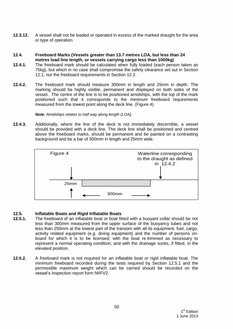
50 1
st Edition
1 June 2013
12.3.12. A vessel shall not be loaded or operated in excess of the marked draught for the area
or type of operation. 12.4. Freeboard Marks (Vessels greater than 13.7 metres LOA, but less than 24
metres load line length, or vessels carrying cargo less than 1000kg) 12.4.1. The freeboard mark should be calculated when fully loaded (each person taken as
75kg), but which in no case shall compromise the safety clearance set out in Section 12.1, nor the freeboard requirements in Section 12.2.
12.4.2. The freeboard mark should measure 300mm in length and 25mm in depth. The
marking should be highly visible, permanent and displayed on both sides of the vessel. The centre of the line is to be positioned amidships, with the top of the mark positioned such that it corresponds to the minimum freeboard requirements measured from the lowest point along the deck line. (Figure 4) Note: Amidships relates to half way along length (LOA).
12.4.3. Additionally, where the line of the deck is not immediately discernible, a vessel should be provided with a deck line. The deck line shall be positioned and centred above the freeboard marks, should be permanent and be painted on a contrasting background and be a bar of 300mm in length and 25mm wide.
12.5. Inflatable Boats and Rigid Inflatable Boats 12.5.1. The freeboard of an inflatable boat or boat fitted with a buoyant collar should be not
less than 300mm measured from the upper surface of the buoyancy tubes and not less than 250mm at the lowest part of the transom with all its equipment, fuel, cargo, activity related equipment (e.g. diving equipment) and the number of persons on-board for which it is to be licensed; with the boat re-trimmed as necessary to represent a normal operating condition; and with the drainage socks, if fitted, in the elevated position.
12.5.2. A freeboard mark is not required for an inflatable boat or rigid inflatable boat. The
minimum freeboard recorded during the tests required by Section 12.5.1 and the permissible maximum weight which can be carried should be recorded on the vessel’s inspection report form IWFV2.
Waterline corresponding to the draught as defined
in 12.4.2
300mm
25mm
Figure 4
51 1
st Edition
1 June 2013
12.5.3. Vessels, which do not meet the freeboard requirement of Section 12.5.1 at the transom, may still be accepted by the PLA provided it can be demonstrated that the boat is self-draining when moving ahead, and has a substantial reserve of buoyancy (>10%). Any deviation from the requirements of this Standard will be recorded on the report form IWFV2.
12.6. Draught Scales 12.6.1. All vessels over 13.7 metres load line length shall bear permanent draught scales.
These shall be displayed as follows:
a) at the aft end of the vessel, no more than one sixth L forward from the aft end of the vessel on both port and starboard sides;
b) at the fore end of the vessel, no more than one sixth L aft from the fore end of the vessel, on both port and starboard sides.
12.6.2. The zero points on each draught scale shall be taken from the plane running parallel
to the plane of maximum draught, passing through the lowest point of the hull, or of the keel where such exists. The scale of decimetres, or metres and decimetres, denoting a draught shall be marked as follows:
a) in figures in two-decimetres intervals, if the scale is in decimetres; or
b) in figures at each metre interval and at intervening two-decimetres intervals, if the scale is in metres and decimetres; and
c) the capital letter ‘M’ being placed after each metre figure;
d) the top figure of the scale showing both the metre and (except where it marks a full metre interval) the decimetre figure;
e) the lower line of the figures, or figures and letters (as the case may be), coinciding with the draught line denoted thereby; and
f) the figures and letters being not less than 1 decimetre in length and being marked by being cut in and painted white or yellow on a dark ground, or in such a way as the PLA approves.
12.6.3. Existing vessels with draught scales which fail to comply with the requirements of
Section 12.6 will be assessed on a case by case basis by the PLA.

52 1
st Edition
1 June 2013
13. LIFE-SAVING APPLIANCES 13.1. General 13.1.1. All life-saving appliances must be marked in accordance with the guidelines of
Marine Guidance Note MGN 105 (M+F) – “Use and Fitting of Retro-reflective Material on Life-saving Appliances”.
13.1.2. Subject to agreement with the PLA, the requirements of Section 13 do not apply to Dumb vessels or Collar barges; however persons working on board these vessels shall at all times wear a suitable self inflating lifejacket which complies with the requirements of Section 13.4.
13.2. Availability, Stowage and Maintenance of Life Saving Appliances 13.2.1. All items of life-saving and survival equipment9 required by this Standard shall be:
a) periodically serviced in accordance with the manufacturers instructions;
b) mounted or stowed correctly in their assigned locations;
c) maintained in good working order in accordance with the manufacture’s instructions and be ready for use.
13.2.2. The minimum required life-saving equipment is summarised in Table 13.1 below.
TABLE 13.1
Carriage Requirements for Life-saving Appliances
Area of Operation Vessel Size Category C Category D
Liferaft Containing
SOLAS B equipment pack
All Recommended
(See Section 13.3.1) Yes
Lifebuoys with light <24m 1 1
≥24m 2 2
Lifebuoys with line <24m 1 1
≥24m 2 2
Lifejackets Min 100%
(See Section 13.4)
Min 100% (See Section 13.4)
Red Hand Held Flares 0 2
Buoyant Orange Smoke Float Flares 0 2
Thermal Protective Aids 0 Min 100%
See 13.6
General Alarm 750Kw installed power Yes Yes
30m Buoyant Heaving Line 1 1
9 Refer to MGN 362 (M+F) – Servicing of Inflatable Liferafts, Inflatable Boats, Rescue Boats, Fast Rescue Boats
(RIBs), Inflatable Lifejackets and Hydrostatic Release Units, for further guidance on servicing of inflatable equipment and Hydrostatic release units.

53 1
st Edition
1 June 2013
13.3. Liferafts 13.3.1. All vessels operating in Category D Waters and not exempted by Section 13.1.2 shall
have a liferaft(s) with sufficient capacity for all persons on board. It is recommended that vessels operating in Category C Waters also comply with this requirement.
13.3.2. Liferaft(s) should be constructed to SOLAS standard, Marine Equipment Directive
Approved (MED)or Department for Transport (DfT) approved; and in general, be contained in fibre reinforced plastic (FRP) containers (which may be a suitable container other than a SOLAS container) stowed on the weather deck or in an open space. The liferaft(s) should also be fitted with float free arrangements (hydrostatic release unit) so that the liferafts(s) float free, inflate and break free automatically. Other stowage and release mechanisms may be considered if they can be demonstrated, to the satisfaction of the PLA, to provide an equivalent level of safety.
13.3.3. The liferaft(s) provided should be manufactured either;
a) in accordance with Section 13.3.2, and be equipped with “SOLAS B PACK”; or
b) to the ISAF OSR Appendix A Part 2 requirements. Liferaft(s) should be equipped to a level equivalent to that of a "SOLAS B PACK". This may, where necessary, include a "grab bag" to supplement the equipment integral to the liferaft; or
c) to the ISO 9650 – Small Craft Inflatable Liferafts, Part 1, Type 1, Group A standard, provided the liferaft(s) are fitted with a boarding ramp; are equipped to the level of “SOLAS B PACK”, which may, where necessary, include a “grab bag” to supplement the equipment integral to the liferaft, and are certificated as compliant with Part 1, Group A and Part 3 of ISO 9650 from March 2005 onwards.
13.3.4. All liferafts should be serviced at a service station approved by the manufacturer and
at the manufacturer’s recommended intervals. However, where the liferaft(s) are stored in valises, servicing should be at least annually.10
13.3.5. Inflatable liferaft hydrostatic release units11 (other than the types which have a date
limited life and are test fired prior to disposal) should be serviced annually by the manufacturer’s approved agent.
13.3.6. To facilitate rapid abandonment in an emergency, where a ‘grab bag’ is provided, it
should be in an accessible and clearly marked position known to all on board. 13.3.7. The vessel’s emergency procedures and SMS must include arrangements for
warning the crew when the vessel is about to be abandoned. 13.3.8. For vessels with embarkation areas, positioned more than 3 metres above the
waterline, ladders or other suitable means shall be provided to allow for safe embarkation into liferafts.
13.3.9. Liferaft launching and emergency embarkation positions (including the water into
which the liferaft is launched) shall be effectively illuminated.
10
MGN 362 (M+F) provides further guidance on the servicing of inflatable liferafts, inflatable lifejackets and hydrostatic release units.
11 MGN 343 (M+F) – “Hydrostatic Release Units (HRU) – Stowage and Float Free Arrangements for Inflatable Liferafts.

54 1
st Edition
1 June 2013
13.4. Lifejackets 13.4.1. Lifejackets shall be tested and comply with MCA (DfT) or MED approval
(“Wheelmarked”), alternatively they shall comply with BS EN ISO 12402-3-2006 for lifejackets of 150 Newtons or BS EN ISO 12402-2-2006, for lifejackets of 275 Newtons or an equivalent ISO/CEN standard.
13.4.2. Lifejackets that comply with BS EN 399 or BS EN 396 and hold a current servicing
certificate, where applicable, may continue to be used where already fitted on a vessel at the time of this Standard being implemented.
13.4.3. All lifejackets shall be fitted with a whistle, retro-reflective materials and an automatic
light. 13.4.4. There shall be a minimum of one lifejacket per person on-board. Inflatable lifejackets
are permitted, however if inflatable lifejackets are carried, there shall be in addition to the number of persons on-board, two spares.
13.4.5. Inflatable lifejackets for new vessels, and new inflatable lifejackets for existing
vessels are to be of the compressed gas inflation type, with either manual or automatic activation, and fitted with oral top up valves. Lifejackets which rely solely on oral inflation, are not permitted.
13.4.6. Compressed gas inflatable lifejackets should be serviced to manufacturers’
recommendations within a maximum of one month either side of the Compliance, Renewal and Intermediate inspections. In the intervening years they are to be examined annually (Unless stated otherwise by the manufacturer) inline with the manufacturer’s instructions. Certification or declaration of servicing must be available for inspection by the PLA. Visual examinations of the lifejackets should be carried in accordance with the requirements of the owner’s Safety Management System.
13.4.7. It is most strongly recommended that no more than two different types of lifejacket
are permitted on any vessel, to limit any confusion in use. 13.4.8. Where the design of the vessel allows, donning instructions for the types of
lifejackets carried shall be posted in a position(s) that is clearly visible to all persons on-board the vessel.
13.5. Lifebuoys 13.5.1. All lifebuoys should be marked with the vessel’s name in a clearly contrasting colour
to the background. 13.5.2. Lifebuoys and their holders shall comply with harmonized standards BS EN
14144:2003 ‘Lifebuoys Requirements & tests’ and BS 14145:2003 ‘Holders for Lifebuoys’.
13.5.3. There shall be at least two lifebuoys on vessels of less than 24 metres in load line
length and four lifebuoys on vessels of 24 metres and over, load line length, at least one of which shall by located by the wheelhouse.
13.5.4. On vessels of less than 24 metres load line length, at least one lifebuoy shall be fitted with a buoyant line of not less than 18 metres in length12. On vessels of 24 metres
12
Guidance on lifebuoy buoyant lines and grab-lines can be found in MGN 106 (M+F)12.

55 1
st Edition
1 June 2013
and over, load line length, at least two lifebuoys shall be provided a buoyant line of not less than 30 metres in length.
13.5.5. In addition to the requirements of Sections 13.5.4, any vessel operating between the
hours of sunset and sunrise shall carry on-board, an automatic battery-powered light, which can not be extinguished by water, suitably connected to a second lifebuoy. On vessels of 24 metres and over, load line length, this shall be increased to two such lights suitably attached to two separate lifebuoys.
13.5.6. Small inflatable vessels and Rigid Hull Inflatable Boats may in lieu of the requirements prescribed in Section 13.5.3, be provided with a minimum of one rescue quoit and one floating rescue strop; both shall be provided with 18m buoyant lines attached.
13.5.7. An efficient means to aid the recovery of a person from the water should be provided
to the satisfaction of the PLA. 13.6. Thermal Protective Aids (TPAs) 13.6.1. For vessels operating in Category D Waters, TPAs should be provided for all persons
that a vessel is licensed to carry, unless the vessel is fitted with a canopied liferaft. 13.6.2. TPAs should be approved as meeting the standards of the MED (Wheelmarked) and
may be stowed in the ‘grab bag’. 13.7. General Alarm 13.7.1. A general alarm is required for vessels with 16 or more persons on-board and for all
vessels where total installed power (propulsion and electrical generation) is greater than 750 kW.
13.7.2. The general alarm may be a bell, siren or klaxon, or the vessel's whistle, providing it
can be heard in all parts of the vessel. 13.7.3. In engine spaces and pump rooms the alarm signal shall, in addition to the sound
signal, take the form of a flashing light that is clearly visible on all sides of the space. 13.7.4. Vessels less than 24 metres load line length and where the total installed power
(propulsion and generators) is 750Kw or less, should comply with Sections 13.7.1, 13.7.2 & 13.7.3, where reasonably practicable, or should be able to demonstrate effective communication to all parts of the vessel, which may be manned, in the case of an emergency.
13.8. Pyrotechnics13 13.8.1. All pyrotechnics should be MED approved (“Wheelmarked”) or should comply with
MSN 1676 (M) - “The Merchant Shipping (Life-Saving Appliances for Ships Other Than Ships of Classes III to VI (A)) Regulations 1999”, as amended. (Note - Hand held smoke signals need not be approved to the MED or MSN 1676 (M)).
13.8.2. Vessels operating solely in Category C Waters are exempt from the carriage of
pyrotechnics under this Standard.
13
Further guidance can be found in MGN 287 (M+F) – “Disposal of Out of Date Pyrotechnics”

56 1
st Edition
1 June 2013
14. FIRE SAFETY 14.1. General 14.1.1. The engine space shall be capable of being closed down in order to restrict the
spread of fire. Any ventilation fans located within, or feeding a machinery space, should be capable of being stopped from outside the space in the event of a fire. Fan systems incorporating automatic stops which activate in the event of a fire, must be supplemented with a manual override.
14.1.2. For vessels less than 24 metres load line length, where it is not practical to have a
machinery space, the engine should be enclosed in a box. The box should perform the same function as the machinery space boundaries in Section 14.1.1.
14.1.3. Combustible materials should not be stowed in the engine space, except where they
are stowed in a metal container with a secure lid. Any materials or equipment stowed in the engine space should be adequately secured against movement and protected from coming into contact with machinery or hot surfaces, and cause no obstruction for access or egress to the space.
14.1.4. Provision should be made to retain any oil or fuel leakage within the confines of the
engine space; and oils should be stored inline with the requirements of Section 7.3.2.
14.1.5. The engine space should be kept clean and clear of oily waste, except where oily waste and combustible materials are stored inline with Section 7.3.2 & 14.1.4 respectively.
14.1.6. In a vessel constructed of wood, measures should be taken to prevent unnecessary absorption of oil into the structure.
14.1.7. Portlights or windows should not be fitted in the internal boundary of the engine
space; except that an observation port having a maximum diameter of 150mm may be fitted in an internal boundary bulkhead, provided that the port is of the non-opening type; the frame is constructed of steel or other equivalent material, and the port is fitted with a permanently attached cover with securing arrangements. Only fire rated toughened safety glass, rated A0 in accordance with the FTP Code14, should be used in an observation port.
14.2. Vessels where the Total Installed Power Exceeds 750 kW 14.2.1. Steel Construction: Vessels which have their engine space boundaries constructed of
steel require no additional fire protection. However, surfaces on the opposite side of the engine space bulkhead(s) should only be coated with finishes which have a Class 1 surface spread of flame rating when tested in accordance with the requirements laid down in the FTP Code14. (Appendix 1)
14.2.2. Fibre Reinforced Plastic (FRP) Construction: Engine space boundaries should be
constructed of a material capable of preventing the passage of smoke and flame for 15 minutes, when tested in accordance with the FTP14 Code (Appendix 1). Suitable fire resistance of FRP may be achieved by the use of woven roving glass layers or additives, which must be added to the resin strictly in accordance with the manufacturer’s requirements.
14
International Code for the Application of Fire Test Procedures

57 1
st Edition
1 June 2013
Intumescent polyester, epoxy, vinyl-ester or phenolic resin surface coatings may also be used. However, solvent borne intumescent paints are not acceptable. The PLA may waive the requirement for the testing if the construction complies with an ISO or equivalent standard to give at least the same level of protection.
14.2.3. Aluminium and/or Wood Construction: Engine space boundaries should have an
equivalent level of fire protection to that provided in Section 14.2.2. 14.3. Insulation 14.3.1. Thermal or acoustic insulation fitted inside the engine space should be of non-
combustible material. 14.3.2. Thermal or acoustic insulation will be considered as being a non-combustible
material if it complies with BS EN ISO 4589 Part 3, and the material has an Oxygen Index greater than 21.
14.3.3. Insulation should be protected against impregnation by flammable vapours and
liquids. Where insulation is cut, the edges should be protected against such impregnation, e.g. by the use of non-combustible tape. Where the insulation is vulnerable to damage it should be protected.
14.3.4. Where insulation is fitted to provide an equivalent level of fire protection to that
required in Sections 14.2.2 or 14.2.3, the insulation need not be fitted lower than 300mm below the waterline.
14.3.5. Where it is not possible for the vessels described in Section 14.2.2 to meet the fire
test requirements of the FTP Code, or those vessels described in Section 14.2.3 to meet an equivalent level of fire protection, such vessels may be fitted with insulation which provides an equivalent level of fire protection to the machinery space boundaries. Insulation that has been approved to meet A-15 standards (with steel) will be considered to meet this standard. The insulation need not be fitted lower than 300mm below the light waterline on the hull sides.
14.4. Open Flame Gas Appliances 14.4.1. Open flame gas appliances provided for cooking, heating or any other purposes,
should comply with the requirements of EC Directive 90/396/EEC (Council Directive of 20 June 1990 on the approximation of the laws of the Member States relating to appliances burning gaseous fuels), so far as the requirements of the Directive apply to any particular appliance, and be suitable for marine use and installation aboard vessels.
14.4.2. Installation of a gas appliance should be in accordance with a recognised standard
listed in the Standards of Appendix 1 or equivalent as agreed by the PLA. 14.4.3. Materials which are within the distances of open flame cooking or heating appliances,
as described in Section 14.4.1, should be non-combustible, except that these materials may be faced with any surface finish having a Class 1 surface spread of flame rating when tested in accordance with a recognised standard, (see Standards contained in Appendix 1).
14.4.4. Combustible materials, and other surfaces, which do not have a surface spread of
flame rating, should not be left unprotected when sited within the following distances of a cooker:

58 1
st Edition
1 June 2013
a) 400mm vertically above the cooker, for horizontal surfaces, when the vessel is upright; and
b) 25mm horizontally from the cooker, for vertical surfaces.
14.4.5. Curtains, or any other suspended textile materials, should not be fitted within 600mm
of any open flame cooking, heating or other appliance. 14.4.6. ISO 9094-1 or ISO 9094-2 (Small Craft Fire Protection) will be considered as
acceptable under the requirements of Sections 14.4.4 & 14.4.5. 14.4.7. Audible Carbon Monoxide (CO) detection/alarms should be provided in enclosed
living quarters, accommodation and the wheelhouse where the accumulation of CO may occur through inefficient combustion of hydro carbons. This includes spaces provided with heat via ducting from an appliance containing a combustion chamber.
14.5. Fuel-Fired Heating, Cooking and Refrigerating Equipment 14.5.1. Heating, cooking and refrigeration equipment running on liquefied gas shall meet the
appropriate standards listed in Appendix 1. 14.5.2. Heating, cooking and refrigeration equipment, together with its accessories, shall be
so designed and installed such that it is not dangerous even in the event of overheating. It shall be suitably installed that it cannot overturn or be moved accidentally.
14.5.3. The intake of air necessary for combustion and the exhaust from the combustion
chamber shall comply with the requirements of Section 5.5.
14.5.4. Heating appliances shall be securely connected to flues, which shall be fitted with suitable cowls or devices affording protection against the wind. They shall be temporarily removable such as to permit cleaning.
14.5.5. Forced-air heating appliances consisting of a combustion chamber around which the
heated air is conducted under pressure to a distribution system, or to an internal area, shall meet the following requirements:
a) If the fuel is vaporised under pressure the combustion air shall be supplied by a blower;
b) The combustion chamber shall be well ventilated before the burner may be lit. This ventilation may be considered complete when the combustion air blower continues to operate after the flame has extinguished;
c) The fuel supply shall be automatically cut if:
i) the flame is extinguished;
ii) the supply of combustion air is no longer adequate;
iii) the heated air exceeds a previously set temperature; or
iv) the electricity supply is no longer reaching the safety devices;
In the above cases the fuel supply shall not be re-established automatically after being cut off.
d) It shall be possible to switch off the combustion air and heating air blowers from outside the areas to be heated;

59 1
st Edition
1 June 2013
e) Where heating air is drawn from outside the vessel, the intake vents shall be located as far as practicably possible above the weatherdeck. They shall be installed in such a manner that rain and spray cannot be inducted;
f) Heating air pipes shall be made of metal;
g) It shall not be possible to completely close the heating air outlet apertures;
h) It shall not be possible for any leaking fuel to reach the heating air pipes;
i) It shall not be possible for forced-air heating appliances to draw their heating air from an engine room.
14.5.6. Audible Carbon Monoxide (CO) detection/alarms should be provided in accordance
with Section 14.4.7. 14.5.7. The equipment referred to in Sections 14.5, 14.6 & 14.7 shall not be installed in
areas in which substances with a flash point below 55°C are used or stored; and flues from the installations described in Sections 14.5 & 14.6 shall not pass through such areas.
14.6. Use of Liquid Fuels - Oil-Fired Equipment Only fuels with a flash point above 55°C shall be used in oil fired equipment. 14.7. Vaporising Oil Burner Stoves and Vaporising Oil Burner Heating Appliances 14.7.1. Vaporising oil burner stoves and vaporising oil burner heating appliances shall be
built in accordance with a current recognised standard acceptable to the PLA. 14.7.2. Where a vaporising oil burner stove or a vaporising oil burner heating appliance is
installed in an engine space, the air supply to the heating appliance and the engines shall be so designed that the heating appliance and the engines can operate properly, safely and independently of one another. Where necessary, there shall be a separate air supply. The equipment shall be installed in such a way that no flame from the burner can reach other parts of the engine space installations.
14.7.3. Where Vaporising oil burner stoves are fitted the following shall apply:
a) It shall be possible to light vaporising oil burner stoves without the aid of another combustible liquid. They shall be fixed over a metal drip pan which encompasses all the fuel-carrying parts and is at least 20mm high and has a capacity of at least two litres.
b) For vaporising oil burner stoves installed in an engine room, the metal drip pan prescribed in Section 14.7.3 a) shall be at least 200 mm deep. The lower edge of the vaporising burner shall be located above the edge of the drip pan. In addition, the drip pan shall extend at least 100 mm above the floor.
c) Vaporising oil burner stoves shall be fitted with a suitable regulator which, at all settings, ensures a virtually constant flow of fuel to the burner and which prevents any fuel leak should the flame be extinguished. Regulators shall be considered suitable when they continue to function, even when shaken or tilted by up to 12°, and which, in addition to a level-regulating float, have:
i) a second float which works safely and reliably to shut off the fuel supply when the permitted level is exceeded; or

60 1
st Edition
1 June 2013
ii) an overflow pipe, if the drip pan has sufficient capacity to accommodate the contents of the fuel tank.
14.7.4. Where the fuel tank of a vaporising oil burner stove is installed separately:
a) the drop between the tank and the burner feed may not exceed that set out in the manufacturer's operating instructions; and
b) it shall be installed so as to be protected from unacceptable heating; and
c) it shall be possible to interrupt the fuel supply from outside the space.
14.7.5. The flues of vaporising oil burner stoves shall be fitted with a device to prevent
draught inversion.
14.7.6. Where Vaporising oil burner heating appliances are fitted, they shall comply in particular with the following requirements:
a) adequate ventilation of the burner shall be ensured before the fuel is supplied;
b) the fuel supply shall be regulated by a thermostat;
c) the fuel shall be ignited by an electric device or by a pilot flame;
d) a flame monitoring device shall cut off the fuel supply when the flame goes out; and
e) the main switch shall be placed at an easily accessible point outside the space.
14.8. Furnishing Materials 14.8.1. Combustion Modified High Resilient (CMHR) foams shall to be used in all
upholstered furniture and mattresses; except where an existing vessel can not fully comply, they shall do so as far as practicable
14.8.2. Upholstery covering fabrics should satisfy the cigarette and butane flame tests of a
recognised standard. (FTP Code or equivalent). 14.9. Fire Detection 14.9.1. For new build vessels where the total installed aggregate power (propulsion and
electrical generation) is greater than 750 kW, efficient fire detectors should be fitted in the machinery space(s). This requirement is strongly recommended for existing vessels.
14.9.2. On any vessel, where any area is identified by the PLA as posing a risk of fire to
either passengers or crew (e.g. galleys, sleeping accommodation), appropriate fire detection equipment shall be installed to protect that area.
14.9.3. The fire detectors should be suitable to the hazard identified and should provide an
appropriate warning (audible or visual), that can be heard in the space concerned, in the accommodation and at the control position when the vessel is operating under any conditions.

61 1
st Edition
1 June 2013
14.10. Means of Escape 14.10.1. Two means of escape should be provided in:
a) accommodation spaces used for sleeping or rest;
b) other accommodation spaces affected by the risk of fire; and
c) engine spaces affected by a fire risk except:
i) those spaces visited only occasionally, or unmanned during normal operations, and where the single access gives ready escape, at all times, in the event of fire; or
ii) those spaces where the total floor area (average length × average width at the level of the floor plating) of the engine space does not exceed 35m²; or
iii) those spaces where any person entering, and moving about the space, is within 5m of the single entrance, at all times.
14.10.2. The means of escape should be such that a single hazardous event will not cut-off
both routes of escape. Only in exceptional cases, for example, that the overall safety of the vessel would be diminished, will means of escape contrary to Section 14.10.1 be considered by the PLA.
14.10.3. Exceptionally, where a single means of escape from accommodation spaces is
accepted, efficient fire detectors should be provided, as necessary, to give early warning of a fire emergency which could cut off that single means of escape.
14.10.4. Means of escape should be clearly marked for their purpose on both sides, and the
function of each escape route demonstrated by practical tests, to the satisfaction of the PLA.
14.10.5. When considering a means of escape, the requirements of Sections 5.2.1 & 5.3.3
should also be considered. 14.10.6. Stairways and ladders providing access or egress to engine spaces, accommodation
and holds shall be firmly attached, constructed of steel or another shock-resistant and non-combustible material, unless otherwise agreed by the PLA.

62 1
st Edition
1 June 2013
15. FIRE APPLIANCES 15.1. General 15.1.1. A vessel should be provided with efficient fire fighting equipment compliant with the
standards set out in Appendix 2, and in accordance with this Section. 15.1.2. All equipment is to be serviced in accordance with the servicing intervals in Table 1
of MGN 276 (M+F)15, and undertaken by a competent person as required by BS 5306-3:2009.
15.1.3. Carbon dioxide type fire extinguishers should not be located or provided for use in
accommodation spaces where the user or occupants may be affected by their use or leakage, except where there is a specific risk of an electrical fire. Consideration should be given to the volume of carbon dioxide that could be safely released within the enclosed space.
15.1.4. All vessels fitted with a galley, cooking area or similar, where a risk of fire is
identified, shall have a fire blanket of a recognised standard, (see Appendix 1). 15.2. Vessel Specific Requirements
15.2.1. Open Vessels, Inflatable Boats and Boats with a Buoyant Collar up to 8m in
Length Overall not fitted with a Substantial Enclosure An open vessel, inflatable boat or boat with a buoyant collar, up to 8metres in length, not fitted with a substantial enclosure, with no cooking appliances, should be fitted with a minimum of one fire extinguisher, with a minimum rating of 5A/34B.
15.2.2. Vessels Less than 13.7 metres Length Overall, and Carrying 15 or Less
Persons, Not Covered by Section 15.2 Vessels less than 13.7 m in length, and carrying 15 persons or less, not covered by Section 15.2 shall carry:
a) one hand fire pump (outside engine space)16 or one power-driven fire pump (outside engine space), with sea and hose connections, capable of delivering one jet of water to any part of the vessel through a hose and nozzle, and one fire hose of adequate length fitted with a suitable 10mm spray/jet nozzle; or alternatively,
b) one multi-purpose fire extinguisher of a recognised standard, (see Appendix 1), with a minimum fire rating of 5A/34B, or a combination of smaller extinguishers, giving the equivalent fire rating, in addition to that required in table 15.6.1.
15
MGN 276 (M+F) – “Maintenance of Portable Fire Extinguishers”. 16
This may be one of the pumps required by Section 10 (Bilge Pumping), when fitted with a suitable change over
arrangement which is readily accessible.

63 1
st Edition
1 June 2013
15.2.3. Vessels of 13.7 metres and over, Length Overall, But Less Than 24 metres Load Line Length, or a Vessel Carrying 16 or More Persons Vessels of 13.7 metres or more in length overall, but less than 24 metres load line length, or a vessel carrying 16 or more persons shall carry:
a) one hand fire pump (outside engine space)17 or one power-driven fire pump (outside engine space), with sea and hose connections, capable of delivering one jet of water to any part of the vessel through a hose and nozzle, and one fire hose of adequate length fitted with a suitable 10mm spray/jet nozzle; or alternatively,
b) not less than two multi-purpose fire extinguishers of a recognised standard, each with minimum fire rating of 13A/113B, or a combination of smaller extinguishers giving the equivalent fire rating, in addition to that required in table 15.6.1.
15.2.4. Vessels of 24 metres and Over Load Line Length Vessels of 24 metres and over, load line length should carry one power-driven fire pump (outside engine space), with sea and hose connections, capable of delivering one jet of water to any part of the vessel through a 75mm hose and nozzle, and one fire hose of adequate length fitted with a suitable spray/jet nozzle. This requirement is in addition to the fire extinguishers stated in Table 15.6.1 for vessels 13.7 metres and over length overall.
15.3. Requirements for Portable Extinguishers 15.3.1. Portable fire extinguishers shall meet the following standards:
a) The extinguishing substance used in the portable fire extinguishers required by Sections 15.1 & 15.2 shall be suitable for at least the fire category that is most likely to occur within the area for which the extinguisher is intended.
b) The extinguishing substance on board vessels whose electrical systems have a service voltage of more than 50 V shall also be suitable for fighting electrical fires. The instructions for use shall be clearly set out on each portable extinguisher.
c) The extinguishing substance must not be Halon or contain a product, which is likely to release toxic gases during use, such as Carbon Tetracholoride or Bromochlorodifluoromethane (BCF). Portable fire extinguishers using CO2 may only be used to fight fires at specific locations such as control panels galleys and kitchens. The quantity of CO2 used should not constitute a health hazard.
d) Extinguishers that are sensitive to freezing or to heat shall be installed or protected in such a way that their proper function is always guaranteed.
15.3.2. Where space constraints make it impractical to mount a single fire extinguisher of the
required size, a combination of smaller extinguishers may be used providing the aggregated combination satisfies the requirements of this Standard.
15.3.3. Fire extinguishers shall be serviced at the manufacturer’s recommended service
intervals by an authorised service agent. A certificate to that effect signed by the person having carried out the service shall be kept on board.
17
This may be one of the pumps required by Section 10 (Bilge Pumping), when fitted with a suitable change over
arrangement which is readily accessible or alternatively may be a portable power driven pump.

64 1
st Edition
1 June 2013
15.3.4. If extinguishers are installed in such a way that they are out of sight, the panel covering them shall be identified by an appropriate symbol in accordance with the requirements of MSN 1763 (M+F). Table 15.6.1 - Fire Extinguisher Requirements
Location Type 5A/34B for
vessels <13.7m LOA
Type 13A/113B for vessels ≥13.7m
LOA
a) In the wheelhouse: 1 portable fire
extinguisher
1 portable fire
extinguisher
b) Close to each means of access to the deck and accommodation;
1 portable fire
extinguisher
1 portable fire extinguisher
c) Close to each means of access to service premises that are not accessible from the accommodation, and which contain heating, cooking or refrigeration equipment using solid or liquid fuels:
1 portable fire
extinguisher
1 portable fire
extinguisher
d) At each entrance to the engine space and boiler rooms:
1 portable fire
extinguisher
1 portable fire
Extinguisher
e) At suitable points in engine rooms and boiler rooms such that no position in the space is more than 10m away from an extinguisher, unless this provision is meet by (d).
1 portable fire
extinguisher
1 portable fire
extinguisher
f) By the galley / kitchen 1 fire blanket. 1 fire blanket.
15.3.5. Provision for Fire Extinguishing in Engine Space All vessels fitted with inboard engines should be provided with an efficient and effective means of extinguishing a fire within any engine space. That outcome may be achieved by either a:
a) Fixed Fire Extinguishing System; or
b) Effective means of extinguishing the fire from outside the space and/or safe entry into the space.
It is strongly recommended that consideration is given to Fixed Fire Extinguishing Systems (Section 15.4), capable of extinguishing a fire, without the requirement for persons to enter the space. Alternatively this may consist of a portable fire extinguisher, arranged to discharge into the engine space, operable without entering the space e.g. through a fire hole. The size of the extinguisher should be suitable for the size of the engine space with a minimum type rating of B (Liquid fires).

65 1
st Edition
1 June 2013
15.4. Fixed Fire Extinguishing Systems
When a fixed fire extinguishing system is installed in an engine space, it should be of an MCA or equivalent approved type. The system should be appropriate in size and type for the space to be protected, and be installed and maintained in accordance with the manufacturer’s requirements. All fixed fire extinguishing systems shall comply with the requirements of MSN 1666.
15.5. Additional Requirements for Tankers 15.5.1. Tankers of 150gt or more shall have a fixed fire installation fitted in all cargo pump
rooms, which meet the requirements set out MSN 1666.
15.5.2. All tankers should be provided with a large mobile foam appliance, whereby foam is immediately available by simple and rapid means of operation for discharge in the area of the cargo manifolds. The provisions of SOLAS Chapter II-2, Regulation 10.8.1.3 should be followed as far as practicable.

66 1
st Edition
1 June 2013
16. RADIO COMMUNICATIONS EQUIPMENT 16.1. Radio Installation 16.1.1. A fixed Marine VHF radio must be provided on-board all vessels, except that open
vessels under 13.7 metres load line length may carry a portable (i.e. hand held) VHF Radio in lieu of a fixed VHF radio.
16.1.2. All vessels 24 metres and over load line length shall be provided with a portable VHF
radio on-board, in addition to the fixed VHF required under Section 16.1.1. 16.1.3. Aerials should be mounted as high as is practicable to maximise performance. When
the main aerial is fitted to a mast which is equipped to carry sails, an emergency aerial should be provided.
16.1.4. A fixed radio installation should be clearly marked with the vessel’s name, call sign
and a Maritime Mobile Service Identity (MMSI) number where applicable. A card or cards giving a clear summary of the radio distress, urgency and safety procedures should be displayed in full view of the radio operating position(s).
16.1.5. All radio installations should be:
a) located such to ensure the greatest possible degree of safety and operational availability; and
b) protected against the harmful effects of water, extremes of temperature and other adverse environmental conditions;
16.1.6. Vessels operating in Category D waters should carry an additional means of
communication.
16.2. Electrical Supply 16.2.1. When a battery supplies the source of power for radio equipment, charging facilities
sufficient to maintain battery power required for the radio equipment, should be provided on board; alternatively a duplicate battery of sufficient capacity for the passage, shall be provided.
16.2.2. The electrical supply to radio equipment should be protected against flooding /
swamping as far as practicable and arranged such that radio communications are not interrupted in adverse conditions.
16.3. Radio Personnel - Competency A vessel should carry at least one person suitably qualified to deal with distress and
safety communications. This person should hold a certificate of competence in VHF radio communications acceptable to the PLA18.
16.4. Vessel Radio Licence Owners should be aware that a vessel with radio communications equipment
on board is required to have a Ships’ Radio Licence19 issued by the relevant authority.
18
The issue and enforcement of these certificates of competency is the responsibility of OFCOM. 19
The issue and enforcement of these licences is the responsibility of OFCOM.

67 1
st Edition
1 June 2013
17. NAVIGATION LIGHTS, SHAPES AND SOUND SIGNALS 17.1. A vessel should comply with the requirements of the Merchant Shipping (Distress
Signals and Prevention of Collisions) Regulations 1996, (SI 1996 No. 75), as amended; and PLA Byelaws where applicable.
17.2. A vessel which operates only between sunrise and sunset, and in favourable
weather, is not required to carry navigation lights where it can be demonstrated that the vessel will not be caught in restricted visibility.
17.3. Vessels 24 metres and over load line length should be provided with current indicating lights or other equivalent devices for the monitoring of navigation lights. The indicating devices shall be installed in the wheelhouse unless, it is possible to monitor the navigation lights directly from the wheelhouse, without the requirement of such aids.
17.4. Sound signalling equipment should comply with the requirements of SI 1996 No. 7520,
as amended. A vessel of less than 12 metres in length overall is not obliged to carry the sound signalling equipment required by SI 1996, No. 75, provided that another means of making an efficient sound signal with a portable device is provided.
17.5. If it can be demonstrated to the satisfaction of the PLA that, for a particular vessel,
full compliance with this Section is impracticable, then application should be made to the PLA for consideration of equivalent arrangements, taking into account the nature and area of operation of the vessel concerned.
17.6. Table 17.1 gives a summary of minimum navigation lights, shapes and sound
signalling appliances for specific vessels and does not cover all possible operations. For operations not referenced in the table and associated notes, clarification should be sought through the Regulations stated in Section 17.1, namely SI 1996 No.75 and PLA Byelaws.
20
SI 1996 No.75 - Merchant Shipping (Distress Signals and Prevention of Collisions) Regulations 1996

68 1
st Edition
1 June 2013
TABLE 17.1 - Lights, shapes and sound appliances (see Section 17.6)
Length Overall
Power-driven vessels when underway At anchor Not under command
Aground Sound appliances
Less than 7m
Sidelights1, 4 + All round white2
Required 2, 7, 8, 10
Not required 2, 12
Not required Means to make an efficient sound signal required
More than 7m
But less than
12m
Sidelights1 + All round white2
OR
Sidelights1 + Masthead2 + Stern light2
OR
(if lights have to be offset from centreline) combined lantern sidelights (Bi-light) plus either all round white or masthead and stern light.
Required 2, 8, 10
Not required 2, 12
Not required
Means to make an efficient sound signal required
More than 12m
But less than 20m
Sidelights2 + Masthead3 + Stern light2 Required
2, 8, 10
Required 2, 9, 10,11
Required 2, 10, 13, 14
Whistle required
More than 20m but less than
50m
Sidelights2 + Masthead5 + Stern Light2
Required 2, 8
Required 2, 9,11
Required 2, 11, 14
Whistle and bell required approved by UK nominated bodies
More than 50m but less than
100m
Sidelights3 + Stern Light3 + One Masthead6
Forward + One Masthead6 abaft of, and higher than the forward Masthead Light
Required 3, 9
Required 3, 11
Required 3, 14
Bell located forward + Whistle
100m +
Sidelights3 + Stern Light3 + One Masthead6
Forward + One Masthead6 abaft of, and higher than the forward Masthead Light
Required 3, 9
Required 3,11
Required 3, 14
Bell located forward + gong located aft + Whistle

69 1
st Edition
1 June 2013
1. Lights shall be visible at a range of 1 nautical mile.
2. Lights shall be visible at a range of 2 nautical miles.
3. Lights shall be visible at a range of 3 nautical miles.
4. Vessels not exceeding a maximum speed of 7 knots, may display only a single all round white light, but should show sidelights if practicable.
5. Lights shall be visible at a range of 5 Nautical Miles.
6. Lights shall be visible at a range of 6 Nautical Miles.
7. Anchor light is only required when anchored in or near a narrow channel, fairway or anchorage, or where other vessels may normally navigate.
8. By Night, all round white light where best seen; by day one black ball (0.6 metres in diameter) in the fore part of the vessel.
9. A vessel over 50m shall by day exhibit, in the fore part of the vessel one black ball, and by night the following:
a. in the fore part of the vessel, an all round white light; and
b. at or near the stern, and at a lower level than the light prescribed in 10a, an additional all round white light.
10. Size of the daytime shapes and distances apart may be reduced commensurate with size of vessel.
11. By night, two all round red lights in a vertical line two metres apart and the lowest not less than four metres above the hull (weatherdeck); by day two black balls (0.6 metres in diameters) in a vertical line, 1.5 metres apart.
12. Vessels of less than 12 metres in length, except those engaged in diving operations, shall not be required to exhibit the lights and shapes prescribed.
13. The distances for the lights may be reduced to one metre apart and two metres above the hull (weatherdeck).
14. By night two all round red lights in a vertical line 2 metres apart plus anchor light; by day three black balls (0.6 metres diameter) in a vertical line, 1.5 metres apart. A vessel of less than 12 metres in length, when aground, shall not be required to exhibit the lights or shapes prescribed.
Notes
i) All lights, whistles and bells when they are required to be carried must be type approved for the size of vessel on which they are fitted.
ii) For vessels engaged in other activities i.e. towing, pilotage etc; attention should be paid to the requirements and arrangements for additional lights and shapes.
iii) In the case of open boats, vertical heights should be measured from the gunwale, and in the case of inflatable boats, or boats fitted with a buoyant collar, from the top of the collar or tubes.

70 1
st Edition
1 June 2013
18. NAVIGATIONAL EQUIPMENT 18.1. Compass 18.1.1. All vessels operating in Category D Waters21 shall be fitted with an efficient compass,
as well as means of correcting heading and bearings to true at all times (e.g. a valid deviation card for a magnetic compass). The compass or repeater should be positioned so as to be clearly readable by the helmsman at the main steering position. For vessels operating at night a compass display should be illuminated.
18.1.2. Where a compass is carried on any vessel, it shall be properly adjusted and its table
or curve of residual deviations available at all times. Magnetic compasses should be adjusted when:
a) they are first installed;
b) they become unreliable;
c) the vessel undergoes structural repairs or alterations that could affect its permanent and induced magnetism;
d) electrical or magnetic equipment close to the compass is added, removed or altered; or,
e) a period of two years has elapsed since the last adjustment and a record of compass deviations has not been maintained, or the recorded deviations are excessive or when the compass shows physical defects.
18.1.3. Where a fluxgate or GPS compass are fitted, a suitable back-up power supply must
be provided to power the compass in the event of failure of the main electrical supply. Where a fluxgate compass incorporates a capability to measure magnetic deviation by undertaking a calibration routine, and where the deviation figures are recorded within the device, a deviation card is not required.
18.2. Publications In meeting the requirements of PLA General Directions, publications carried are to be
sufficient to plan, monitor and display the vessel’s route for the intended passage, and where appropriate to plot positions throughout. The publications shall include:
a) appropriate paper navigation charts, such as the PLA A2 colour chart folios for the area of operation;
b) an electronic chart display and information system (ECDIS) may be accepted as an alternative to paper navigation charts;
c) tide tables;
d) current Notices to Mariners;
e) copies of PLA Byelaws, General Directions and Permanent Notice to Mariners;
f) applicable local and national Codes of Practice; and
g) if navigating through the bridges in central London, it is recommended that a copy of the PLA’s “Mariners Guide to Bridges on the Tidal Thames” is carried on-board.
21
Vessel operating within a 0.5Nm radius of their operation will not be required to comply with Section 18.1.1

71 1
st Edition
1 June 2013
19. OTHER EQUIPMENT FOR ALL VESSELS 19.1. General
The following shall be on board all vessels:
a) a pair of binoculars, minimum (7×50) for enclosed vessels operating below the Thames Barrier;
b) a vessel should be provided with an efficient waterproof electric lamp suitable for signalling
c) Tugs shall be equipped with a sufficient number of certificated towing ropes that are suitable for their operation.
d) a 30m heaving line; and
e) a boat hook;
19.2. Radar Reflector A radar reflector should be provided for vessels with non-metallic hulls, either passive
or active (powered), that meet the standards laid down in BS EN ISO 8729.

72 1
st Edition
1 June 2013
20. ANCHORS AND CABLES 20.1. General 20.1.1. Subject to the requirements of Section 20.4, all power-driven vessels are to be
provided with a minimum of one bow anchor with sufficient length of cable to anchor effectively within the vessel’s area of operation.
20.1.2. Tug and barge combinations that involve pushing ahead or towing alongside should
be provided with an effective bow anchor or stern anchor that meet the requirements of Sections 20.2, 20.3, 20.5, 20.6, 20.7 & 20.8.
20.1.3. Provision is to be made for the secure storage of the anchor and its cable, such that it can be readily deployed.
20.1.4. Where an anchor on-board a vessel meets Class Rules, and has been issued with an
anchor certificate, that anchor and cable does not need to meet the requirements of this Standard.
20.1.5. The design of the anchor is to be acceptable to the PLA. 20.1.6. Stainless steel and aluminium anchors will be considered separately dependent upon
the intended use and the test loads for which the anchor has been designed. 20.2. Requirements for Unusual Vessels 20.2.1. For vessels with high windage, due to high freeboard, a large rig, large deckhouses
or superstructures, the mass of the anchor and the anchor cable diameter should be increased above that required in Table 20.1 to correspond to the increased wind loading. The increase in anchor mass and corresponding cable strength is to be to the satisfaction of the PLA.
20.2.2. For vessels of unusual or non-conventional ship form (including pontoon barges), the
anchor and cable size should be to the satisfaction of the PLA. 20.3. Anchoring Operations – All Vessels 20.3.1. An efficient mechanical means should be provided for handling and recovering the
anchors with a mass greater than 30 kg. 20.3.2. Anchoring systems should have the bitter end of the cable secured to the vessel’s
structure and capable of being safely released in an emergency. 20.3.3. There should be a strong securing point on the foredeck or equivalent structure and
where appropriate a fairlead or roller at the stem head. 20.3.4. Anchors are to be rigged ready for use in an emergency at all times when the vessel
is underway. Only where particular operating patterns dictate, may the anchor be left unready, e.g. Pilot boat duties.

73 1
st Edition
1 June 2013
20.4. Additional Requirements for Vessels Navigating Above Cherry Garden Pier 20.4.1. Tugs & barge combinations, that involve pushing ahead or towing alongside,
navigating above Cherry Garden Pier, where the length overall of the tug and barge combination exceeds 50m, should be provided with both bow and a stern anchoring arrangements, that meet the requirements of Sections 20.2, 20.3, 20.6, 20.7 & 20.8.
20.4.2. All powered vessels over 50m length overall, navigating above Cherry Garden Pier
should, in addition to the bow anchor required by Section 20.1, be provided with a stern anchor meeting the requirements of Sections 20.2, 20.3 & 20.7.2.
20.4.3. Operators of tugs and barges, where barges are towed astern of the tug above
Cherry Garden Pier; and the combined length of the tug and barges (excluding the towing medium) exceeds 50m, must submit a formal risk assessment to the PLA to address the anchoring arrangements of the tow combination22.
20.5. Anchors & Cables for Vessels Less Than 24 metres Load Line Length 20.5.1. Vessels less than 24 metres load line length shall be provided with an anchor as
required by the tabulated values for anchor masses in Table 20.1, which refer to ‘High Holding Power’ anchors. Anchors of other designs may be accepted based on the stated holding power.
20.5.2. When an Admiralty pattern type anchor is provided, the mass given in Table 20.1
should be increased by 33% but the diameter of the anchor cable need not be increased.
20.5.3. The length of anchor cable attached to the main anchor should be appropriate to the
area of operation but generally should be not less than 3 x the maximum depth of water within the vessel’s area of operation or 30m, whichever is the greater.
20.5.4. The cable for main anchors may be of chain, wire or fibre rope. 20.5.5. When the anchor cable is of fibre rope, there should be not less than 10m or 20% of
the minimum required cable length, whichever is the greater, of chain between the rope and the anchor. For open boats, this may be reduced to 5m. Where the anchor cable is wire then proposals to substitute the chain tail by an anchor and/or chain of enhanced mass will be considered to the satisfaction of the PLA, with special attention paid to the anchor performance, i.e. catenary curve of the cable.
20.5.6. The use of anchor wires instead of anchor chains is permitted. However, the wires shall have the same tensile strength as that required for chains, but shall be 20% greater in length. A short length of chain is to be fitted between the wire and anchor where practical, having a length equal to 12.5m or the distance from the anchor in the stowed position to the winch, whichever is the shorter. Where the anchor cable is wire then proposals to substitute the chain tail by an anchor and/or chain of
22
Surveyors Notes – Stern Anchors will be required on such barges unless the tug meets the following criteria:
- The tug engaged in towing the barges is twin screw - The tug is provided with twin rudders with back up steering arrangements - The tug is provided with separate fuel tanks for each engine - The propulsion engines of the tug are able to be fed from either fuel tank and the supply is fitted with
un-interruptible dual filter arrangements - There is a robust and effective maintenance regime in place for the tug; and
- The tug master holds a Towing / Pushing Endorsement or equivalent.

74 1
st Edition
1 June 2013
enhanced mass will be considered to the satisfaction of the PLA, with special attention paid to the anchor performance, i.e. catenary curve of the cable.
TABLE 20.1
ANCHORS AND CABLES High holding power anchors - For vessels less than 24 metres load line length
Mean Length of Vessel
Anchor Mass Anchor Cable Diameter
Metres Main (KG) Main
Chain (mm) Rope (mm)
6 8 6 12 7 9 8 12 8 10 8 12 9 11 8 12
10 13 8 12 11 15 8 12 12 18 8 14 13 21 10 14 14 24 10 14 15 27 10 14 16 30 10 14 17 34 10 14 18 38 10 16 19 42 12 16 20 47 12 16 21 52 12 16 22 57 12 19 23 62 12 19 24 68 12 19
Notes: Chain cable diameter given is for short link chain.
1. The rope diameter given is for nylon construction. When rope of another construction is proposed, the breaking load should be not less than that of the nylon rope specified in the table.
2. When anchors and cables are manufactured to imperial sizes, the metric equivalent of the anchor mass and the cable diameter should not be less than the table value.
20.6. Bow Anchors for Vessels of 24 metres and Over Load Line Length 20.6.1. The type and size of anchors and cables for vessels 24 metres and over, load line
length, may be approved by a Classification Society or, may comply with the requirements of Sections 20.6 & 20.8.

75 1
st Edition
1 June 2013
20.6.2. The total mass P of the anchors may be obtained from the following formula:
P = k BT [kg] Where k is a coefficient that takes account of the relationship between length L and beam B, and of the type of vessel. B is the Beam of the vessel; and T is the Draught of the vessel
k = c (L/ (8.B)) for barges, however, k=c will be taken.
c is an empirical coefficient given in the following table.
Deadweight tonnage Coefficient (c)
≤400 t 45
> 400 and ≤650 t 55
> 650 and ≤1000 t 65
> 1000 t 70
20.6.3. On vessels whose deadweight is not greater than 400t and which, owing to their design and intended purpose, are only used on predetermined short-haul passages, the PLA may accept that only two-thirds of total mass P is required for the bow anchors.
20.6.4. The anchor masses established in accordance with the requirements of Section
20.6.2 may be reduced for certain special anchors, in accordance with Classification Society Inland Waterway Rules.
20.6.5. The total mass P specified for bow anchors may be distributed among one or two
anchors. It may be reduced by 15 % where the vessel is only equipped with a single bow anchor and the hawse pipe is located on the centre line. The mass of the lightest anchor should not be less than 45% of that total mass.
20.6.6. Cast iron anchors shall not be permitted. 20.7. Stern Anchors 20.7.1. All tugs requiring a stern anchor under Section 20.4.1 shall be fitted with stern
anchors whose total mass is equal to 50% of the greatest mass P calculated in accordance with the requirements of Section 20.6.2 for the largest formation of barges allowed for the vessel.
20.7.2. All power-driven vessels and towed barges requiring a stern anchor under the
requirements of Sections 20.4.2 & 20.4.3 shall be fitted with stern anchors whose total mass is equal to 50% of the mass P calculated in accordance with the requirements of Section 20.6.2.
20.7.3. The total mass P specified for stern anchors may be distributed between one or two
anchors. The mass of the lightest anchor should be not less than 45% of the total mass required.
76 1
st Edition
1 June 2013
20.8. Anchor Cables for Vessels 24 metres and Over Load Line Length 20.8.1. Each anchor cable shall have a minimum length of the vessel’s length overall + 10m
or 3x the maximum depth of water within the vessel’s area of operation, whichever is the greater.
20.8.2. The minimum tensile strength of the anchor chains shall be calculated by means of
the following formulae: a) anchors having a mass of 0-500 kg:
R = 0.35P’ [kN]; b) anchors having a mass of more than 500 kg and not exceeding 2000 kg:
R = (0, 35 – ((P' – 500)/15000)) P’ [kN]; c) anchors having a mass of more than 2000 kg:
R = 0.25 P’ [kN]. In these formulae P’ is the theoretical mass of each anchor determined in accordance with the requirements of Section 20.6.2. Anchor chains shall be designed and tested in accordance EN 14330:2003. Where the anchors have a mass greater than that required by Section 20.6.2, the tensile strength of the anchor chain shall be determined as a function of that highest anchor mass.
20.8.3. The attachments between anchor and chain shall withstand a tensile load 20% higher than the tensile strength of the connected chain.
20.8.4. The use of anchor wires instead of anchor chains is permitted. However, the wires
shall have the same tensile strength as that required for chains, but shall be 20% greater in length. A short length of chain may be fitted between the wire and anchor where practical, having a length equal to 12.5m or the distance from the anchor in the stowed position to the winch, whichever is the shorter.

77 1
st Edition
1 June 2013
21. ACCOMMODATION AND RECREATIONAL FACILITIES 21.1. General Requirements – All Vessels 21.1.1. All vessels, should as a minimum, comply with the requirements of Section 21.1.2.
21.1.2. Accommodation shall be so designed, arranged and fitted out as to meet the health,
safety and comfort needs of those on board, taking fully into account the vessel’s intended operational activity. It shall be safe and easy to access / egress23, and shall be insulated against heat and cold. A deckhouse used for the accommodation of persons must be constructed of adequate strength to withstand the forces of weather to which it will be subjected during use.
21.1.3. The PLA may allow a relaxation of the requirements of Section 21 of this Standard if the health and safety of those on board are ensured by other means.
21.2. Securing of Equipment 21.2.1. Items of equipment and stores should be securely fastened as necessary to prevent
movement due to the motion of the vessel. 21.2.2. Stowage lockers should have lids or doors with secure fastenings. 21.3. Hand Holds and Grab-Rails There should be sufficient hand holds and grab-rails within the accommodation to
allow for safe movement around the vessel under any sea conditions reasonably expected in the vessel’s operational area.
21.4. Ventilation 21.4.1. There should be adequate ventilation in all accommodation spaces. 21.4.2. Where air conditioning systems are not fitted, mechanical ventilation should be
provided to accommodation spaces, which are situated completely below the level of the weather deck, on vessels which carry nine or more berthed persons below the deck. As far as practicable, such ventilation arrangements should be designed to provide at least six changes of air per hour when the access openings to the spaces are closed.
21.4.3. It shall be possible to heat the accommodation in accordance with its intended use.
Heating installations shall be appropriate for the weather conditions which can reasonably be expected in the vessel’s operational area.
21.5. Lighting An electric lighting system should be installed which is capable of supplying
adequate light to all enclosed accommodation and working spaces.
23
For detailed requirements on means of escape from accommodation, see Section 14.10.

78 1
st Edition
1 June 2013
21.6. Domestic Hot Water Systems Domestic hot water systems should be designed, installed and maintained for the
pressure and temperature at which they are intended to operate inline with the manufacturer’s instructions and safety guidance.
21.7. Water Services An adequate supply of potable water should be provided at convenient positions
throughout the accommodation spaces. 21.8. Galley 21.8.1. When a cooking appliance is gimballed it should be protected by a crash bar or other
means to prevent it being tilted when it is free to swing. In addition a means should be provided to lock the gimbal mechanism to prevent movement.
21.8.2. Cooking appliances should be provided with fiddler rails or such other device as to
prevent items becoming dislodged when in use. There should be secure storage for food, utensils and equipment in the vicinity of the food preparation and cooking area.
21.9. Stowage Facilities for Personal Effects Adequate stowage facilities for clothing and personal effects should be provided for
each person on board. 21.10. Vessels Used For Overnight Accommodation 21.10.1. When a vessel is intended for use for overnight accommodation, an adequate
standard of accommodation should be provided for all persons on board. In considering such accommodation, primary concerns should be directed towards ensuring the health and safety aspects of persons, e.g. the ventilation, lighting, water services, galley services and the access / escape arrangements.
21.10.2. Vessels which are used for overnight accommodation and where the main source of
power may be isolated, ie generator shut down or batteries isolated, the vessel should be provided with suitable fire and Carbon Monoxide detection devices within the accommodation space, which operate independently of the vessel’s power supply and provide an audible alarm of sufficient volume so as to awaken resting persons on board.
21.10.3. Sleeping Accommodation A separate bunk or cot should be provided for each person on board and at least
50% of those provided should be fitted with lee boards or lee cloths unless otherwise agreed by the PLA.
21.11. Excessive Noise and Vibration Excessive noise and vibration should be limited within accommodation spaces, and
as far as practicable in accordance with relevant international standards. Where the crew’s exposure to noise and vibration is very limited in accommodation spaces, alternative arrangements may be accepted. Further guidance on noise and vibration standards can be found in Section 22.10.

79 1
st Edition
1 June 2013
21.12. Galley A galley should be fitted with a means for cooking, a sink and have adequate clean working surface for the preparation of food.
21.13. Toilet Facilities 21.13.1. Adequate toilet facilities, separated from the accommodation, should be provided for
persons on board. 21.13.2. In general, there should be at least one flushing marine toilet and one wash hand
basin for every 12 persons. 21.13.3. Due consideration should be given to the requirements of Section 29, Pollution
Prevention. 21.14. New-Build Vessels - Additional Requirements For Accommodation 21.14.1. All new build vessels should comply with the requirements of Section 21 in its
entirety. Where Section 21.14 lays down specific requirements which are above that required in Sections 21.1 through to 21.13, the requirements of Section 21.14 for new-build vessels shall be applied.
21.14.2. Where there is no deck-level access to the accommodation and the difference in
level is 0.30m or more, the accommodation shall be accessible by means of stairways and companionways.
21.14.3. Stairways shall be permanently fixed and safely negotiable. They shall be deemed to
be so when:
a) they are at least 0.60m wide;
b) the tread is at least 0.15m deep;
c) the steps are non-slip; and
d) stairways with more than three steps are fitted with at least a handrail or handle.
21.14.4. Doors shall have a total height, coamings included, of at least 1.90m and a clear
width of at least 0.60m. The prescribed height may be achieved by means of sliding or hinged covers or flaps. Coamings shall not be more than 0.40m high, but shall nonetheless comply with the provisions of other safety regulations.
21.14.5. Doors shall be so arranged that they can be opened and closed safely from either
side; in front of the access opening, there shall be sufficient room not to impede movement. Doors shall be protected against accidental opening or closing.
21.14.6. Points of access and passageways for the movement of persons and objects shall be
of sufficient size that the clear width of the passageway shall be appropriate for the intended use of the working space, and shall be not less than 0.60m, except in the case of vessel less than 8m wide, where it may be reduced to 0.50m.
21.14.7. Headroom in the accommodation shall be not less than two metres.
21.14.8. In the fore Section of the vessel, no floor shall be more than 1.20m below the plane
of maximum draught.

80 1
st Edition
1 June 2013
21.14.9. Sleeping quarters shall have at least two exits which serve as escape routes and are separated as far as practicably possible; one exit may be designed solely as an emergency exit. This does not apply to areas with an exit leading directly onto the deck or onto a corridor which serves as an escape route, provided the corridor has a separate exit leading to the weather deck on both port and starboard sides. Emergency exits, which may include skylights and glazing shall have a clear opening of at least 0.36m² and, a shortest side no less than 0.50m, and permit rapid evacuation in the event of an emergency. Escape routes shall be faced and insulated with fire-resistant materials and their usability guaranteed at all times by appropriate means such as ladders or rungs. In addition, the accommodation shall receive adequate daylight and, as far as reasonably practicable, provide a view out.
21.14.10. Pipes carrying dangerous gases or liquids, and particularly those under high
pressure in which the slightest leak could pose a danger to human life, shall not be located in the accommodation or in corridors leading to the accommodation. An exception is permitted for steam pipes, hydraulic system pipes and for the pipes of liquefied gas installations for domestic purposes, provided they are fitted in metal sleeves.
21.14.11. Furnishings shall meet the requirements of domestic fire retardant materials. –
Assessment of the ignitability of upholstered furniture – BS 5852-1
21.14.12. Heating and Ventilation 21.14.12.1. It shall be possible to adequately ventilate the accommodation even when the doors
are closed. The inflow and evacuation of air shall ensure adequate air circulation in all climatic conditions.
21.14.12.2. The accommodation shall be designed and arranged as to prevent, so far as reasonably practicable, the ingress of foul air from other areas of the vessel, such as engine rooms or holds; where forced-air ventilation is used the intake vents shall be so placed as to satisfy the above requirements.
21.14.12.3. The volume of air per person shall be at least 3.5m³ in the accommodation. In the sleeping quarters it shall be at least 5m³ for the first occupant and at least 3m³ for each additional occupant (not counting volume of furniture). Sleeping cabins shall, as far as possible, be intended for no more than two persons. Berths shall be not less than 0.30m above the floor. Where one berth is placed over another, the headroom above each berth shall be not less than 0.60m.
21.14.13. Sanitary Installations 21.14.13.1. The following sanitary installations shall be the minimum provided on-board a vessel
fitted with accommodation:
a) one toilet per accommodation unit or per six crew members, which it shall be possible to ventilate with fresh air;
b) one wash basin serviced by hot and cold potable water and suitably connected to a waste pipe, per accommodation unit; and
21.14.13.2. Holding tanks shall be provided to retain black waste water.
81 1
st Edition
1 June 2013
21.14.13.3. The sanitary installations shall be in close proximity to the accommodation. Toilets shall not have direct access to galleys, mess rooms or combined day-rooms/galleys. However, on vessels of less than 24 metres load line length, or designed for use on narrow canals, where this requirement cannot be complied with due to space constraints on board, the toilet may open directly off a galley/ mess room or day rooms, provided that a hand basin is available, in the toilet compartment.
21.14.13.4. Toilet compartments shall have a floor space of at least 1m², not less than 0.75m wide and not less than 1.10m long. Where a toilet contains a wash basin and/or shower, the surface area shall be increased at least by the surface area occupied by the wash basin and/or shower (or bath).
21.14.14. Galleys 21.14.14.1. Vessels with accommodation shall have a galley, sufficient to meet the needs of the
number of persons on-board. This may be combined with day-rooms.
21.14.14.2. Galleys shall comprise:
a) a cooker;
b) a sink with waste connection;
c) a supply of potable water; and
d) sufficient storage and working space.
21.14.14.3. The eating area of combined galleys/day-rooms shall be large enough to
accommodate the number of crew normally using it at any one time.
21.14.14.4. The galley and eating area, where these exist, shall be well lit, suitably ventilated and easy to clean.
21.14.15. Potable Water 21.14.15.1. Vessels with accommodation shall have one or more potable water tanks. Potable
water tank filling apertures and potable water pipes shall be marked as being intended exclusively for potable water. Potable water filler pipes shall extend above the deck in order to avoid contamination.
21.14.15.2. Potable water tanks shall:
a) be protected against excessive heating;
b) have a capacity of at least 100 litres per person normally using the accommodation;
c) be made of a material which resists corrosion and poses no physiological danger;
d) have a water level indicator;
e) have breather pipes to the open air, fitted with appropriate filters; and
f) be provided with openings having leak-proof closures that are intended to permit cleaning and inspection.
21.14.15.3. For vessels less than 24 metres load line length designed to operate on categorised
water with ready access to potable water sources alongside, the capacity of the potable water tank may be reduced, provided that it is of an adequate capacity to supply potable water to the crew at all times when they are on board.

82 1
st Edition
1 June 2013
21.14.15.4. Potable water tanks shall not share boundaries with other tanks.
21.14.15.5. Potable water pipes shall not pass through tanks containing other liquids. Connections are not permitted between the potable water supply system and other pipes. Pipes carrying gas or liquids other than potable water shall not pass through potable water tanks.
21.14.15.6. Potable water pressure vessels shall operate only on uncontaminated compressed air. Where it is produced by means of compressors, appropriate air filters and oil separators shall be installed directly in front of the pressure vessel, unless the water and the air are separated by a diaphragm.
21.14.16. Overnight Accommodation 21.14.16.1. Accommodation shall be so designed, arranged and fitted out as to meet the health,
safety and comfort needs of those on board, taking fully into account the vessel’s intended operational activity.
21.14.16.2. Vessels shall have at least one day-room partitioned off from the sleeping quarters.
For vessels less than 24 metres load line length, the PLA may authorise exceptions.
21.14.16.3. The cubic capacity of each unit in the living and sleeping quarters shall be not less than 7m³.
21.14.16.4. The free floor area of the living quarters shall be not less than 2m² per person, and in any event not less than 8m² in total (not counting furniture, except tables and chairs).
21.14.16.5. Each crew member living on board shall have an individual berth and an individual clothes locker fitted with a lock. The internal measurements of the berth shall be not less than 2.00m × 0.90m.
21.14.16.6. Suitable local lighting shall be provided for each berth.
21.14.16.7. Suitable places for storing and drying work clothes shall be provided, however this shall not be in the sleeping quarters.
21.14.16.8. Sound pressure levels shall not exceed:
a) 70 dB(A) in the living quarters;
b) 60 dB (A) in the sleeping quarters.
21.14.16.9. The galley should be provided with a refrigerator.
21.14.16.10.The capacity of the potable water tank(s) shall be at least 150 litres per person
normally living on board.
21.14.16.11.One shower or bath serviced by hot and cold potable water shall be provided for each accommodation unit.

83 1
st Edition
1 June 2013
22. SAFETY OF PERSONNEL
22.1. General 22.1.1. The owner shall ensure that the vessel is operated without endangering the health
and safety of the crew and any other persons legitimately on board the vessel.
22.1.2. Owners should ensure that vessels licensed under this Standard are operated in compliance with the Code of Safe Working Practice for Merchant Seaman24 and relevant PLA Codes of Practice. However, these Codes should not be considered as comprehensive guides to safety, and the advice they contain should always be considered in conjunction with the findings of the owners assessment of risks, and any information or working instructions provided by the manufacturer, supplier, or any other source, should be followed. The safety of the vessel and her crew ultimately rests with the vessel’s master.
22.1.3. All members of the crew and their health and safety representatives shall be
informed of all measures to be taken regarding health and safety on board the vessel. Such information shall be easily understood by all persons concerned.
22.2. Risk Assessment 22.2.1. A health and safety risk assessment (Regulation 7 of the Merchant Shipping and
Fishing Vessels (Health and Safety at Work) Regulations 1997, No. 2962 as amended) shall be used to satisfy the obligation of providing information to crew members of the measures taken for their own protection.
22.2.2. Where risks to the health and safety of the persons on-board cannot be prevented or
sufficiently limited by collective or technical means, they shall be provided with personal protective equipment (PPE). PPE is the lowest form of protection for personnel in the hierarchy of control measures, and shall not be a substitute for technical measures or Safe Systems of Work that could be undertaken so far as reasonably practicable to reduce or eliminate risks. For further information see The Merchant Shipping and Fishing Vessels (Personal Protective Equipment) Regulations 1999, No 2205 as amended, MSN 1731 (M+F)25.
22.2.3. Personal protective equipment in the form of clothing or over clothing shall be in
bright colours, contrasting with the marine environment and clearly visible. (Reference MSN 1731 (M+F))
22.3. Bulwarks, Guardrails and Handrails 22.3.1. Bulwarks, guardrails and handrails are only required on manned vessels. Where
fitted they should be supported efficiently by stays or stanchions. 22.3.2. To protect persons from falling overboard, bulwarks should be not less than 1000mm
above the deck in accordance with load line regulations. Where this requirement would impede the normal operation of the vessel, if the bulwarks are less than 1000mm, but more than 620mm high, a single guard rail may be provided on top of the bulwark to attain the 1000mm height required. On vessels where no bulwarks exist, or the bulwark height is limited, additional courses of guardrails should be provided to achieve the top rail height of 1000mm from the deck. The distance
24
Code of Safe Working Practices for Merchant Seamen Consolidated Edition, 2010, issued by the MCA 25
MSN 1731 - The Merchant Shipping and Fishing Vessels Personal Protective Equipment Regulations 1999
84 1
st Edition
1 June 2013
between the underside of the lowest course and the deck should not exceed 230mm, and the distance of the opening between other courses should not exceed 380mm. The horizontal distance between vertical stanchions shall not exceed 1.5m
22.3.3. Guardrails should be of either solid or wire rope construction, of suitable diameter
and adequately tensioned so as not to allow the guardrail to sag or flex excessively when leant against. Chain substitutes are not acceptable under this Standard, except where the guardrail is required to be removed to provide means of access or egress.
22.3.4. For vessels where it is impractical to fit guardrails, alternative arrangements may be
acceptable subject to the satisfaction of the PLA as to the adequacy of the proposed arrangements given the design and operation of the vessel, and having considered an appropriate risk assessment undertaken by the owner. For example, on small motor vessels with narrow side decks alongside a deck house, a handrail on the side of the deckhouse may be considered sufficient. On the foredeck, a centreline handrail may also be considered.
22.3.5. Handrails should be provided for stairways, ladderways, passageways and for decks
without bulwarks or guardrails. This provision should not be used in lieu of guardrails and bulwarks where required by this Standard.
22.3.6. In an inflatable boat or a rigid inflatable boat, where it is not possible to fit bulwarks,
handrails or guardrails, there should be handgrips, toeholds and handrails provided as necessary to ensure the safety of all persons on board during transit and the worst weather conditions likely to be encountered in the intended area of operation.
22.4. Alternative Arrangements for Bulwarks, Handrails and Guardrails. 22.4.1. Where the application of the requirements of Section 22.3 would impede26 the proper
working of the vessel, alternative safety measures may be considered, using ISO 15085, subject to the agreement of the PLA.
22.4.2. This alternative provision is not available to vessels licensed as “suitable for single
handed operations”. 22.5. Dimensions of working spaces
Working spaces shall be large enough to provide every person working at that space adequate freedom of movement.
22.6. Protection Against Slips Trips and Falls 22.6.1. General – All Vessels 22.6.1.1. Working areas shall be kept clear and, so far as is reasonably practicable, provide
adequate protection for the crew against falling on the vessel or falling overboard. 22.6.1.2. A safe means of access and egress to and from the vessel shall be provided at all
times. Gangways shall comply with EN526.
26
“Impede” should not be interpreted as “inconvenience”. The PLA must be satisfied that the required height of bulwarks,
guardrails and handrails would “impede” rather than simply inconvenience the proper working of the vessel; and the associated risk assessment and survey records should show why impedance was justified as a reason for acceptance of lower bulwarks, guardrails and handrails
85 1
st Edition
1 June 2013
22.6.1.3. A safe means of access and egress should be provided into all spaces on the vessel, including, but not limited to, tanks, peak spaces and holds, for the purpose of maintenance and inspection.
22.6.1.4. Stairs and ladders shall be securely fixed and the steps be coated with slip resistant
surfaces. Stairs with more than three steps shall also be provided with suitable handrails.
22.6.1.5. Ladders and separately attached rungs shall be clearly recognisable from above and
shall be equipped with safety handles above exit openings.
22.6.1.6. Portable ladders shall be:
a) at least 0,40 m wide;
b) of suitable construction;
c) suitably maintained and inspected; and
d) possible to secure the ladder to ensure that they will not topple or skid when in use.
22.6.2. Existing Vessels 22.6.2.1. Owners operating existing vessels should undertake a risk assessment as identified
in Section 22.2; to ensure the protection of personnel against slips, trips and falls; and implement those risk control measures to the satisfaction of the PLA.
22.6.2.2. Where a vessel is equipped with cargo holds and spaces, provisions should be made, so far as reasonably practicable, to protect personnel from the risk of falls into the cargo holds and/or spaces, whilst working in, and moving around the vessel.
22.6.2.3. Vessels equipped with cargo holds and spaces shall have at least one portable
ladder which complies with Section 22.6.1.6, and can be used to enter or leave the cargo space in complete safety. This requirement shall not apply where an equivalent ladder is fixed permanently in each cargo space.
22.6.3. New-Build Vessels 22.6.3.1. New build vessels should comply with the following requirements:
a) The clear width of the side deck shall be at least 0.60m. This may be reduced to 0.5m at certain points that have been designed for safety of operations such as deck-swabbing cocks. It may be reduced to 0.4m at bollard emplacements.
b) Up to a clear height of 0.90m above the side deck, the clear width of the side deck may be reduced to 0.54m provided that the clear width above, between the outer edge of the hull and the inner edge of the hold, is not less than 0.65m. In this case, the clear width of the side deck may be reduced to 0.50m if the outer edge of the side deck is fitted with a guard rail in accordance with this Standard or European Standard EN 711 to prevent falling. On vessel 55m or less in length with only aft accommodation, the guard rail may be dispensed with.
c) The requirements of a) and b) above shall apply to access areas up to a height of 2m above the side deck.
d) Where a vessel is equipped with holds, provisions should be made to protect personnel from the risk of falls into the hold whilst moving around the vessel.

86 1
st Edition
1 June 2013
e) For vessels less than 24 metres load line length, where it is not possible to comply with the requirements of Sections 22.6.3.1 a), b) & c), alternative measures shall be taken to ensure safe means of access to, and around all working decks.
f) Stairs shall be not less than 0,60m wide and the clear width between handrails shall be not less than 0,60m; steps shall be not less than 0,15m deep
g) Ladders and separately attached rungs shall have a clear width of not less than 0,30m; rungs shall be not more than 0,30m apart and the distance between rungs and structures shall be not less than 0,15m.
22.7. Ventilation of Enclosed Workplaces 22.7.1. Actions shall be taken to ensure there is sufficient fresh air in enclosed workplaces,
having regard to the work methods used and the physical demands placed on the persons working within the space.
22.7.2. If a mechanical ventilation system is used, it shall be maintained in good condition in
line with manufactures guidelines. 22.7.3. Effective means of ventilation shall be provided, temporary or otherwise, for all
enclosed spaces that may be entered by persons on board. 22.8. Natural and Artificial Light of Workplaces 22.8.1. Workplaces shall as far as possible receive sufficient natural light and be equipped
with artificial lighting suitable for the operations in hand, without placing the crew’s health and safety at risk, compromising the navigation of the vessel and the ability to maintain a proper lookout; or jeopardising the navigation of other vessels.
22.8.2. Lighting installations in working areas, stairs, ladders and passageways shall be of
an appropriate design and construction; and sited in such a way that the type of lighting utilised poses no risk of accident to the crew and no hindrance to the navigation of the vessel.
22.8.3. Workplaces in which the crew are especially exposed to risks in the event of failure of
artificial lighting shall be provided with emergency lighting of adequate intensity. 22.8.4. Emergency lighting shall be maintained in an efficient operating condition and be
tested at regular intervals and the records of such tests recorded in the operational safety management system.
22.9. Variable Height Wheelhouses
Variable-height wheelhouses shall be fitted with an emergency lowering system. All lowering operations shall automatically trigger a clearly audible and visual warning signal in the relevant areas of the vessel. This requirement shall not apply if the risk of injury, which may result from the movement of the wheelhouse, is prevented by appropriate design features. It shall be possible to enter and leave the wheelhouse safely whatever its position. A facility shall be provided to lock the raising/lowering mechanism during maintenance.
87 1
st Edition
1 June 2013
22.10. Noise - New-Build Vessels 22.10.1. The noise produced by a vessel under way, and in particular the engine air intake
and exhaust noises, shall be dampened to the following levels, by using appropriate means.
22.10.2. The noise generated by machinery on a vessel under way shall not exceed 75 dB (A)
at lateral distance of 25m from the vessel’s side. 22.10.3. Apart from transhipment operations the noise generated by the machinery on a
stationary vessel shall not exceed 65 dB (A) at a lateral distance of 25m from the vessel’s side.
22.11. General Safety 22.11.1. The owner operating a vessel should carefully consider the design and layout of the
vessel and whether it is suitable for its intended operation, and suitably protects those on-board.
22.11.2. Seating should be designed and located so as to protect personnel from the effects
of whole body vibration, and shock loads27. 22.11.3. As part of the risk assessment required under the General Duties requirements of the
Merchant Shipping and Fishing Vessels (Health and Safety at Work) Regulations 1997 (SI 1997 No. 2962), as amended, the operator is required to carry out a risk assessment for all persons on-board, and their liability is not only limited to their crew.
27
Further guidance can be found in the publications “Small Passenger Craft High Speed Experience Rides”27
“Passenger Safety on Small Commercial High Speed Craft”27
and The Merchant Shipping and Fishing Vessels (Control of Vibration at Work) Regulations 2007 - MGN 353
27.

88 1
st Edition
1 June 2013
23. MEDICAL CARE 23.1. Medical Stores 23.1.1. Medical stores should be carried in accordance with the requirements set out in
Appendix 3 (Medical Stores For Vessels Certificated To Operate In Category C & D Waters).28 This approved Code of Practice requires all employers to provide adequate and appropriate first aid equipment for use in the event of a person being injured at work.
23.1.2. It is the responsibility of the owner to assess the risks of injury to personnel by means of risk assessment as required by Section 22.2, and formally identify any risks that may require the inclusion of additional medical stores above the minimum listed in Appendix 3.
23.1.3. The Master or a member of the Crew should, as a minimum, hold an acceptable Elementary First Aid Certificate which is suitable for the level of medical stores carried on-board.
28
This is compliant with current HSE Health and Safety (First Aid) Regulations 1981, which are supported by the
HSE Approved Code of Practice for First Aid at work.

89 1
st Edition
1 June 2013
24. TENDERS AND DINGHIES 24.1. Where a tender or dinghy is provided solely for transferring persons or carrying
stores directly to and from the parent vessel, it does not need to be licensed. If the tender is also used to carry out additional functions it should be separately licensed by the PLA.
24.2. When a vessel's tender or dinghy is provided (towed or carried by a vessel) it must
be clearly marked with the maximum permissible weight and the maximum number of persons, which can be safely carried and with the name of the parent vessel stating “Tender to XXXX”
24.3. Tenders should be built to the appropriate design category for which it is intended to
be used. All tenders or dinghies should be fit for the intended purpose, regularly inspected by the owner and maintained in a safe condition.
24.4. When vessels are lifted to enable launch and recovery they should be fitted with
lifting points appropriate to the construction of the vessel.
24.5. An inflatable tender should be subjected to an air tightness test undertaken annually, as required by Section 4.6.5.
24.6. Further guidance on Inland Waterways tenders can be found in BSEN1914

90 1
st Edition
1 June 2013
25. TOWING OPERATIONS 25.1 Vessels Engaged in Commercial Towing Operations 25.1.1. Masters engaged in towing operations are to ensure the relevant national legislation,
COLREGS and PLA Byelaws regarding lights and shapes are complied with. Section 11.4 identifies the stability requirements `of vessels engaged in towing operations.
25.1.2. The requirements of this Section do not apply to vessels towing in an emergency
situation. 25.2. Towing Arrangements
The design of towing gear should minimise the overturning moment due to the lead of the towline.
25.2.1. The towline must have a positive means of release which can be relied upon to
function correctly, and safely release the tow under all operating conditions. 25.2.2. The towing hook (or equivalent fitting) and the supporting structure must be strong
enough to withstand loads imposed during towing operations. 25.2.3. The release mechanism must be controllable from all conning positions and at the
towing point. When the towing point is a towing hook, the local control at the hook should be of the direct mechanical type capable of independent operation.
25.2.4. Towing arrangements must be appropriate to the task in hand and maintained to
ensure that they are in an efficient working condition. 25.2.5. The anchors and cables carried by the towing vessel must be suitable to hold both
the towing vessel and the towed vessel. The displacement and windage of the towed vessel must be considered when determining the necessary anchoring arrangements. Section 20 details the anchoring requirements and arrangements.
25.3. Weathertight Integrity 25.3.1. Doorways in superstructures, deckhouses and exposed machinery casings situated
on the weather deck, and which enclose accesses to spaces below deck, must be provided with efficient weathertight doors. Weathertight doors should be secured in the closed position when the vessel is towing and the doors should be marked clearly to this effect.
25.3.2. Machinery air intakes and machinery space ventilators, which must be kept open during towing operations, should be served by means of high coaming ventilators as protection from down-flooding.
25.3.3. Generally, air pipes and ventilators should be kept as far inboard as possible and fitted with an automatic means of closure when downflooding to the compartments would endanger the safety of the vessel.

91 1
st Edition
1 June 2013
26. JACK – UP BARGES 26.1. A vessel which has the capability of a jack-up to operate clear of the surface of the
water falls under the jurisdiction of the Health and Safety Executive when it is jacked up, and should be equipped and certificated to meet the appropriate requirements.
26.2. When the stability standards of Section 11 are not appropriate for assessment of a
particular small non-self-propelled vessel, the case should be referred to the MCA for consideration of stability standards to be applied.
26.3. Further guidance on the operational requirements for Jack Up Barges can be found
in the International Jack Up Barge Owners Association (IJIBOA) Code of Practice.

92 1
st Edition
1 June 2013
27. VESSELS FITTED WITH A DECK CRANE OR OTHER LIFTING DEVICE29
27.1. Section 11 describes the vessel’s stability requirements during lifting operations.
27.2. Generally a vessel fitted with a deck crane or other lifting device should be a decked vessel with a watertight weather deck as required by Section 4.5
27.3. Agreement should be obtained from the PLA for any proposal to fit a deck crane or other lifting device on a vessel which is not a decked vessel with a watertight weather deck.
27.4. The vessel's structure, crane or other lifting device and supporting structure should be of sufficient strength to withstand the loads that will be imposed when operating at maximum capacity.
27.5. Load tests and inspections to verify the safe operation of the crane or other lifting
device, its foundation and supporting structures should be carried out to the satisfaction of the PLA. Tests should be conducted in accordance with a recognised standard for the installation. Such tests should be repeated after any modifications, including any structural modifications.
27.6. Lifting operations and equipment shall comply with the requirements of BS 7121: Part 2:2003 - Code of Practice for Safe Use of Cranes, Inspection, Testing and Examination.
27.7. An inclinometer (pendulum) should be provided on-board for guidance to the crane or lifting device operator when controlling the lifting of items of unknown weight. Wherever practicable a safe load indicator should also be provided on board.
27.8. A clear notice should be posted in a prominent position on, or near the crane or lifting device and contain the following information and instructions:
a) the maximum permitted load and outreach which satisfy the requirements of Section 11.3, or the Safe Working Load (SWL), whichever is the lesser (operating performance data, i.e. load radius performance chart for a crane or other lifting device of variable load-radius type should be included as appropriate);
b) any crane whose SWL varies with its operating radius is provided with a means of accurately determining the radius at any time, clearly visible or accessible to the driver of the crane, showing the radius of the load lifting attachments at anytime. Provision should be made to enable the driver to ascertain the safe working load corresponding to that radius;
27.9. A lifting system which incorporates moveable counterbalance weight(s) shall be
specially considered by the PLA.
29
For the purpose of Sections 27.2, 27.3 & 27.7, a lifting device does not include a person retrieval system, the
vessel’s own anchor handling equipment, or davits for tenders, which are judged by the PLA not to have a detrimental effect on the stability of the vessel.

93 1
st Edition
1 June 2013
27.10. The Merchant Shipping (Lifting Operations and Lifting Equipment) Regulations 2006 (SI 2006 No. 2184), as amended apply to lifting equipment, lifting attachments and the operation of such equipment.

94 1
st Edition
1 June 2013
28. VESSELS OPERATING IN PLANING MODE 28.1. A vessel designed to operate at speed where the helmsmen is not contained within a
wheelhouse or other similar structure, should be provided with an engine stop cord for the main propulsion unit. The stop cord, or Kill Cord should be of suitable length as to connect to the helmsman from the console mounted engine stop switch without impeding their operational role as helmsman. The stop cord should stop the propulsion unit instantly, bringing the vessel to rest.
28.2. Vessels should have suitable seating that allows all persons on-board to effectively
brace themselves from shock loading. Further guidance can be found in MGN436, and MGN353 30
30
Further guidance can be found in the publications “Small Passenger Craft High Speed Experience Rides”
“Passenger Safety on Small Commercial High Speed Craft” , MGN 353 - The Merchant Shipping and Fishing Vessels (Control of Vibration at Work) Regulations 2007 and MGN 453- Whole Body Vibration: Guidance on mitigating against the effects of shocks and impacts on small vessels.
95 1
st Edition
1 June 2013
29. POLLUTION PREVENTION
29.1. Sewage 29.1.1. All new-build vessels fitted with toilet facilities must be provided with a sewage
holding tank(s) with sufficient capacity for the requirements of the vessel and appropriate means to empty the tank(s). Tank venting arrangements should be routed adequately clear of accommodation and sleeping quarters so as not to contaminate the air quality within the spaces. Outlets from tank vents should not be near ventilation or machinery inlets and should not pose a danger to other vessels alongside.
29.1.2. Existing vessels fitted with toilet facilities and not provided with a sewage holding
tank(s) must comply with the requirements of Section 29.1.1 by 1 January 2015.

96 1
st Edition
1 June 2013
APPENDICES 1. Standards Referenced within the Thames Freight Standard 2. Fire Extinguisher Standards 3. Medical Stores for Vessels Certificated to Operate in Category C & D Waters

I 1
st Edition
1 June 2013
APPENDIX 1 Technical Standard Reference in the Thames Freight Standard Technical Standards Numbering refers to the appropriate Section reference. When referencing the standards for use during construction, or supply of equipment, the latest edition should be used. Equivalent standards may be considered subject to the acceptance of the PLA or MCA where applicable.
Standard Title
2010 FTP Code - IMO
International Code for Application of Fire Test Procedures (FTP Code) – International Maritime Organisation Document
ISO 11812:2002
Small Craft. Watertight cockpits and quick-draining cockpits
ISO 6185-2
ISO 6185-3
Inflatable Boats. Boats with a maximum motor rating of 4.5kW to 15kW inclusive
Inflatable Boats. Boats with a maximum motor rating of 15kW and greater
ISO 15372:2000
Ships and marine technology. Inflatable rescue boats. Coated fabrics for inflatable chambers
ISO 12216:2002
Small craft. Windows, portlights, hatches, deadlights and doors. Strength and watertightness requirements.
ISO 7840 Small Craft. Fire resistant fuel hoses
BS EN 61779-4:2000
Electrical apparatus for the detection and measurement of flammable gases
IEC 60092-507 Electrical Installations in Ships – Small Vessels (up to 50m / 500gt)
IEC 60092-401 Electrical Installations in Ships – Installation and test of completed installations
IEC 60536 Classification of electrical and electronic equipment with regard to protection against electric shock. Guide to requirements for protection against electric shock
IEC 60332-1
to 3
Tests on Electrical and Optical Cables Under Fire Conditions
IEC 60092-509 - 2011
The Institution of Electrical Engineers Regulations, Electrical installations in ships – Part 509 Operation of electrical installations., and subsequent supplements.
British Marine Federation Code of Practice for Electrical and Electronic Installations in Boats, 4th Edition.
BS 6883:1999
Specification for elastomer insulated cables for fixed wiring in ships. (Suitable for lighting, power, control, instrumentation and propulsion circuits.)
IEC 92-350
Low-voltage shipboard power cables. (General construction and test requirements for shipboard cables with copper conductors intended for
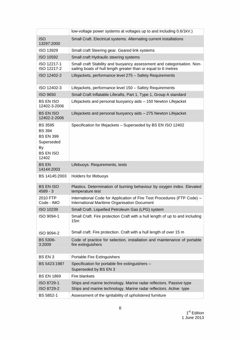
II 1
st Edition
1 June 2013
low-voltage power systems at voltages up to and including 0.6/1kV.)
ISO 13297:2000
Small Craft. Electrical systems. Alternating current installations
ISO 13929 Small craft Steering gear. Geared link systems
ISO 10592 Small craft Hydraulic steering systems
ISO 12217-1 ISO 12217-2
Small craft Stability and buoyancy assessment and categorisation. Non-sailing boats of hull length greater than or equal to 6 metres
ISO 12402-2
Lifejackets, performance level 275 – Safety Requirements
ISO 12402-3 Lifejackets, performance level 150 – Safety Requirements
ISO 9650 Small Craft Inflatable Liferafts, Part 1, Type 1, Group A standard
BS EN ISO 12402-3-2006
Lifejackets and personal buoyancy aids – 150 Newton Lifejacket
BS EN ISO 12402-2-2006
Lifejackets and personal buoyancy aids – 275 Newton Lifejacket
BS 3595
BS 394
BS EN 399
Superseded
By
BS EN ISO 12402
Specification for lifejackets – Superseded by BS EN ISO 12402
BS EN 14144:2003
Lifebuoys. Requirements, tests
BS 14145:2003 Holders for lifebuoys
BS EN ISO 4589 - 3
Plastics. Determination of burning behaviour by oxygen index. Elevated temperature test
2010 FTP Code - IMO
International Code for Application of Fire Test Procedures (FTP Code) – International Maritime Organisation Document
ISO 10239 Small Craft. Liquefied Petroleum Gas (LPG) system
ISO 9094-1
ISO 9094-2
Small Craft. Fire protection Craft with a hull length of up to and including 15m
Small craft. Fire protection. Craft with a hull length of over 15 m
BS 5306-3:2009
Code of practice for selection, installation and maintenance of portable fire extinguishers
BS EN 3 Portable Fire Extinguishers
BS 5423:1987 Specification for portable fire extinguishers –
Superseded by BS EN 3
BS EN 1869 Fire blankets
ISO 8729-1
ISO 8729-2
Ships and marine technology. Marine radar reflectors. Passive type
Ships and marine technology. Marine radar reflectors. Active type
BS 5852-1 Assessment of the ignitability of upholstered furniture

III 1
st Edition
1 June 2013
ISO 15085 Small craft. Man-overboard prevention and recovery
BS 5378 Safety signs and colours
BS 7121 Code of practice for safe use of cranes. Inspection, testing and examination
ISO 10088 Small Craft. Permanently installed fuel systems and fixed fuel tanks
ISO 13591 Small craft. Portable fuel systems for outboard motors
BS EN 28846:1993
Small craft. Electrical devices. Protection against ignition of surrounding flammable gases
ISO 10133 Small Craft. Electrical systems. Extra-low voltage d.c. installations
ISO 11105 Ventilation of Petrol engines and/or petrol tank compartments

IV 1
st Edition
1 June 2013
APPENDIX 2 Fire extinguisher Standards
Section Detail
15.2
Multi-purpose fire extinguishers have a capability to deal with both Category A fires involving solid materials, and Category B fires involving liquids or liquefiable solids, and may be marked with the multipurpose rating, e.g. 5A/34B in Section 15.2.1/ 2 ; 13A/113B in Sections 15.2.3, 15.4.1 and Table 15.6.1.
15.2
15.3
Manufacturers producing extinguishers certified and marked to BS EN 3 cannot revert to the colour schemes contained in the withdrawn BS 5423:1987. The vessel owner must not over paint red BS EN 3 extinguishers to the "old" colours.
15.3.1c)
EC Regulation No. 2037/2000, as amended, on ozone depleting substances prohibits the sale and use of Halons, including material that has been recovered or recycled. No fire fighting equipment containing Halons should be used. Marine Guidance Note MGN 191 (M+F) – “Use of Halon for Fire Extinguishing on Board Ships”, provides further information.
15.2.2
15.2.3
15.2.4
Ballast, bilge or general service pumps may be used as fire pumps providing that they are not normally used for pumping oil. Means are to be provided such that at least one jet of water can reach any part of the vessel normally accessible during operation of the vessel.
15.4
The requirements for fixed fire extinguishing installations are detailed in the Merchant Shipping (Fire Protection – Small Ships) Regulations 1998 (SI 1998 No. 1011), as amended, and in the 1999 edition of the “Fire Protection Arrangements” of the Instructions for the Guidance of Surveyors”, as amended (HMSO publication ISBN 5520007). Further requirements for the installation of fixed fire fighting systems can be found in MSN 1666 (M)31 – “The Merchant Shipping (Fire Protection) Regulations 1998: Fixed fire detection alarm and extinguishing systems”.
15.4
Fixed installations in machinery spaces covered by the references are:
1. medium expansion foam;
2. high expansion foam; carbon dioxide;32
3. pressure water spraying;
4. vaporising fluids (hydrofluorocarbons - HFCs); and
5. aerosols (solid pyrotechnic type).
31
Amended by MSN 1733 (M) – “The Merchant Shipping (Fire Protection) (Amendment) Regulations 1999”. 32
MGN 354 (M+F) – “Fishing and Small Vessels – Safe Operation of Fixed CO2 Gas Fire Extinguishing Systems” provides further guidance.

V 1
st Edition
1 June 2013
APPENDIX 3 Medical Stores for Vessels Certificated to Operate in Category C & D Waters Table 1
Statutory Treatment Requirements
Recommended Specification Quantity
1.Resuscitation Equipment
Mask for mouth to mouth resuscitation
Pocket Face Mask 1
2.Dressing and suturing equipment
Adhesive Elastic bandage Adhesive Elastic Bandage 7.5cm x 4m 1
Disposable polyethylene gloves
Latex free, vinyl 5 pairs
Adhesive dressings Assorted, sterile 20
Sterile bandages with un medicated dressings
(Ambulance dressings)
medium, No.1 (12x10)cm
large, No.2 (20x15)cm
extra large No.3(28x20)cm
6
2
2
Adhesive sutures or zinc oxide bandages
75mm adhesive suture strips 6
Sterile gauze swabs Packet containing 5 sterile gauze pads size 7.5cms x 7.5cms
1
Recommended Additional Items
Scissors stainless steel / or sterile disposable
1pr
Triangular bandages about 90cm x 127cm
4
Medium safety pins, rustless 6
Sterile paraffin gauze dressings 10
Plastic burn bags 1
First Aid Instructions or a First Aid Manual (St John’s, Red Cross or St Andrew’s) should also be included with the Medical Stores.