Embed Size (px)
Citation preview

Doc No. : GDP/EPC-BID-S/09-10/023(F)Date : June 8, 2009Assign No. : GPD/SDE/HPCL/08-09/045Date : September 12, 2008
ENGINEERING, PROCUREMENT & CONSTRUCTION (EPC) BID DOCUMENT
3500 TCD Capacity Sugar Plant Village Sugauli, District East Champaran, Bihar
Technical Specifications
Prepared For
Hindustan Petroleum Corporation Ltd. (HPCL)(A Govt. of India Enterprise)
Petroleum House, 17, Jamshedji Tata Road,Mumbai – 400 022
Prepared By
MITCON Consultancy Services Ltd. (MITCON)Kubera Chambers, Shivajinagar
Pune - 411 005
June, 2009

EPC Bid Document for Sugar Plant at Sugauli, Dist. East Champaran, Bihar, Technical Specifications
Doc No. : GDP/EPC-BID-S/09-10/023(F)Date : June 8, 2009Assign No. : GPD/SDE/HPCL/08-09/045Date : September 12, 2008
EPC BID DOCUMENT
3500 TCD Capacity Sugar PlantVillage Sugauli, District East Champaran, Bihar
CONTENTS
Chapter No. Title Page No.1. Intent of Specifications 12. Project information 23. Design Basis, Scope of Supply, Services & Terminal
Points 5
3.1 Design Basis 53.2 Scope of Supply 73.3 Services 103.4 Terminal Points 114. Technical Specifications 154.1 Cane un-loading / loading 15
4.1.1 Weigh Bridges 154.1.2 Cane Un-loading & Handling 154.2 Cane Preparation 20
4.2.1 Cane Stabilizer & Density Enhancer 204.2.2 Cane Cutter 214.2.3 Swing Hammer Type Heavy Duty Cane Fibrizor 224.2.4 Rake Cane Carrier 234.2.5 Auto Cane Feed Control System 244.2.6 DSM Screens for RJ 264.3 Cane Diffusion 26
4.3.1 De-watering Mills 264.3.2 Rake Type Intermediate Carrier (RIC) after Diffuser 294.3.3 Mill Auxiliary System 314.3.4 Cane Diffuser 364.3.5 Bagasse Elevator 384.3.6 Mass Flow Meters 39

EPC Bid Document for Sugar Plant at Sugauli, Dist. East Champaran, Bihar, Technical Specifications
Doc No. : GDP/EPC-BID-S/09-10/023(F)Date : June 8, 2009Assign No. : GPD/SDE/HPCL/08-09/045Date : September 12, 2008
EPC BID DOCUMENT
3500 TCD Capacity Sugar Plant Village Sugauli, District East Champaran, Bihar
CONTENTS (CONTD.)
Chapter No. Title Page No.4.4 Sugar Process House 40
4.4.1 Juice Heating & Clarification 404.4.2 Sulphur Furnace 424.4.3 Air Blower Fans 434.4.4 Juice Sulphiter & Auto pH Control System 434.4.5 Syrup Sulphitation 444.4.6 Milk of Lime Preparation 454.4.7 Juice Clarifier 454.4.8 Rotary Vacuum Filter 464.4.9 Juice Evaporator Station 47
4.4.10 Online Conductivity Measurement 504.4.11 Syrup & Molasses Storage Tanks 504.4.12 Molasses Conditioning Units 514.4.13 Automatic Brix & Temperature Control Equipment,
Molasses Conditioners 51
4.4.14 Batch Type Vacuum Pans 524.4.15 Seed & Vacuum Crystalizers 554.4.16 Condensers 554.4.17 Injection & Spray Water Pumps 564.4.18 Spray Nozzles & Pond 574.4.19 Cooling, Curing & Grading Plant 574.4.20 Centrifugal Machines 584.4.21 Pug Mills, Magma Mixers & Transient Heaters 604.4.22 Air Compressor & Magma Pumps 614.4.23 Sugar Melter, DSM Screen & Dry Seed Conveyor 61

EPC Bid Document for Sugar Plant at Sugauli, Dist. East Champaran, Bihar, Technical Specifications
Doc No. : GDP/EPC-BID-S/09-10/023(F)Date : June 8, 2009Assign No. : GPD/SDE/HPCL/08-09/045Date : September 12, 2008
EPC BID DOCUMENT
3500 TCD Capacity Sugar Plant Village Sugauli, District East Champaran, Bihar
CONTENTS (CONTD.)
Chapter No. Title Page No.4.4.24 Automatic Brix & Temperature Control Equipment, Sugar
Melter 62
4.4.25 Grass Hoppers, Sugar Elevator, Sugar Grader & Dust Catcher
62
4.4.26 Fully Automatic Sugar Silo & Weighing Machines 644.4.27 Molasses weighing, Final Molasses Tanks & Water Tanks 644.4.28 Sugar Go-downs 664.4.29 Water Conservation & Circulation 664.4.30 Miscellaneous Equipment 664.4.31 Supporting Structure & Material Specifications 69
4.5 Other General Design Criteria 704.6 Interface Piping 755. Energy Efficiency Improvement 785.1 Steam Consumption 785.2 Power Consumption 796. Electrical Distribution System 816.1 General Design Basis 816.2 Scope of Work 866.3 Diesel Generating Set 877. Control & Instrumentation System 897.1 Introduction 897.2 Statutory Requirements 897.3 DCS based Automation 93

EPC Bid Document for Sugar Plant at Sugauli, Dist. East Champaran, Bihar, Technical Specifications
Doc No. : GDP/EPC-BID-S/09-10/023(F)Date : June 8, 2009Assign No. : GPD/SDE/HPCL/08-09/045Date : September 12, 2008
EPC BID DOCUMENT
3500 TCD Capacity Sugar Plant Village Sugauli, District East Champaran, Bihar
CONTENTS (CONTD.)
Chapter No. Title Page No.8. Civil Works 948.1 General 948.2 Design Philosophy & Criteria 948.3 Buildings & Civil Works 1148.4 Important & Common Notes 1249. Spares 12610. Inspection & Testing 12711. Drawings, Data & Information 12812. Guaranteed Performance Parameters 12912.1 Cane Preparation, Milling & Diffusion 12912.2 Clarification 12912.3 Evaporation & Boiling Section 13012.4 Cooling, Curing & Grading of Massecuite 13112.5 Reduced Boiling House Recovery 13212.6 Steam Consumption 13212.7 Power Consumption 13212.8 Performance Trial Period 13212.9 Input & Output Flow Rates 13312.10 Performance Parameters for Bank Guarantee 134

EPC Bid Document for Sugar Plant at Sugauli, Dist. East Champaran, Bihar, Technical Specifications
Doc No. : GDP/EPC-BID-S/09-10/023(F)Date : June 8, 2009Assign No. : GPD/SDE/HPCL/08-09/045Date : September 12, 2008
LIST OF APPENDICES
Appendix No. Title
I Schedule for dismantling of existing buildings & civil works
II List of Approved Makes
III Data Sheets & Drawings to be Submitted by the Tenderers
IV Sketches & Drawings
V Indicative Steam & Condensate Balance
VI Indicative Material Balance & Flow Chart
VII Indicative Water Balance
VIII Condenser Water Cooling System
IX Indicative Continuous Evaporation System with Extensive Vapor Bleeding
X General Construction Specifications
XI List of Workshop Equipment
XII List of Spares
XIII Preliminary Plant Layout, Integrated Sugar, Ethanol & Cogen Power Project
XIV Terms & Conditions for Erection & Commissioning

EPC Bid Document for Sugar Plant at Sugauli, Dist. East Champaran, Bihar, Technical Specifications 1
Chapter – 1
Intent of Specifications
The main intent of the specifications has been to define the equipment, electrical, auxiliaries and civil works for the proposed 3500 TCD capacity modern technology based & efficient sugar plant, being set up co-extensively with 60 KLPD ethanol plant and 20 MW high efficiency grid connected cogen power plant, at Sugauli in East Champaran district of Bihar State, as well as for undertaking demolishing work of existing buildings & civil works at the project site.
The sugar plant will be equipped with energy efficient equipment in all sections and will in-house commercially proven diffusion process for optimum juice extraction, for diversion of 50% juice to ethanol plant and balance to sugar process house for manufacturing white plantation sugar.
The intent of the specifications also has been to achieve continuous and efficient operations throughout the crushing season of the cane preparation, diffuser and the boiling house sections. This will provide continuous un-interrupted supply of bagasse to the concurrent cogeneration power plant and supply of 50% juice to the concurrentethanol plant.
The main goals set are as under:
(a) Providing specific equipment, associated systems, electrical distribution system and associated civil works, mainly to achieve the targeted crushing rate, extraction and boiling house efficiencies and lowest steam and power consumption of the sugar plant, as well as achieve continuous operation.
(b) The design basis for selection of all equipment will consider average crushing rate of 150 TCH (or 3600 TCD) on 24 hr basis.
(c) Achieving targeted electricity consumption for the sugar plant of 19 kWh / MT,with electrical by driven cutter, Fibrizer and de-watering mill and total steam consumption of 22% on cane for 50% capacity of sugar processing house, at average crushing rate of 150 TCH (or 3600 TCD) on 24 hr basis.
(d) Demolishing of existing buildings & civil works at the project site (Refer Appendix – I).

EPC Bid Document for Sugar Plant at Sugauli, Dist. East Champaran, Bihar, Technical Specifications 2
Chapter – 2
Project Information
Name and Address : DGM (Pipeline Projects)M/s. Hindustan Petroleum Corporation Ltd. (A Govt. of India Enterprise)8, Shoorji Vallabhdas MargBallard Estate, Mumbai – 400 001Ph : 022 – 2263 7153, 2265 4110 (D)Fax : 022 – 2263 7184 E-mail : [email protected]
Project Site : Near Village Sugauli,District East Champaran, Bihar
Constitution & Type : A Government of India Enterprise
Project Title : Engineering, Procurement , Construct ion & Commissioning of Sugar Plant at the Project Site
EPC Consultant : MITCON Consultancy Services Ltd., "Kubera Chambers", 1st FloorShivajinagar, Post Box No. 923, PUNE-411005, (INDIA)Ph. No.: 020 – 2553 3309 / 2553 4322Fax No.: 020 – 2553 0305 / 2553 3206
Products : White Plantation Sugar & mixed juice for Ethanol (co-extensively with 60 KLPD ethanol & 20 MW Co-generated Power plants)

EPC Bid Document for Sugar Plant at Sugauli, Dist. East Champaran, Bihar, Technical Specifications 3
Project overview : This EPC bid is invited for dismantling of existing buildings and civil works at the project site, as well a s f o r design, engineering, manufacture, procurement, supply, transportation to site, transit and storage, insurance, storing at site, project management, civil works, mechanical works, e lec tr ical works and I & C works , erect ion, installation, testing, commissioning, performance testing, putting into successful commercial operation and handing over of 3500 TCD sugar plant as specified, so as to achieve targeted crushing rate of 150 TCH and steam and power consumptions of 22 % on cane for 50% sugar process house capacity and 23 kWh/MT respectively, at average crushing rate of 150 TCH (peak 167 TCH) on 24 hr basis.
Installed Capacities of the Integrated Project
: 3500 TCD, on cane diffusion process & 1750 TCD for sugar process house (average 130 crushing days per season)
Site location : Near Sugauli town Distance from nearest town / city
: Sugauli, 2 Km
D i s t a n c e f r o m n e a r e s t railway station
: Sugauli, 0.5 KmMotihari, 25 Km
Distance from nearest airport : Patna, 185 KmDistance from nearest water source
: Gandak River, 2 km
Distance from nearest BSEB EHV substations
: Sugauli, 33 KV (2 Km) & Bettiah (132 KV), 20 Km
Annual Rainfall : 1241 mmAmbient air temperatureMaximumMinimum
::
460C 50C
Data for Seismic Design : Zone IV
Relative Humidity : 70% (average)
Climatic Conditions : Tropical, dry & arid

EPC Bid Document for Sugar Plant at Sugauli, Dist. East Champaran, Bihar, Technical Specifications 4
Design wind pressure : In accordance with provisions of Indian Standards IS:875.
D e s i g n c o o l i n g w a t e r temperature
: 320 C
Soil characteristics at site :Iso-ceramic level (No. of stormy days/year)
: 20
Construction power & water : Construction power and water is in the scope of vendor.

EPC Bid Document for Sugar Plant at Sugauli, Dist. East Champaran, Bihar, Technical Specifications 5
Chapter – 3
Design Basis, Scope of Supply, Services & Terminal points
3.1 Design Basis
3.1.1 Manually harvested, whole, loose & entangled cane supply by bullock-carts, tractor-trailers and trucks up to cane carrier, with side tippers and grab un-loaders for trailers & trucks, in line with general practice in the State of Bihar.
3.1.2 Average cane crushing rate of 3500 TCD or 150 TCH will be achieved with Cane Diffusion Process.
3.1.3 Optimum capacity utilization efficiencies at all sections will be achieved with the help of equipment like suitable cane magnets, Cane flow Stabilizer & Density Enhancer (CSDE), high efficiency de-watering mill, continuous cane diffusion and continuous evaporation station (with two separate evaporator sets, one in operation and one set always standby).
3.1.4 Pol extraction efficiency of +98.5%.
3.1.5 Automatic juice proportioning device for screened mixed juice at the outlet of the diffusion process to transfer 45-50% of Mixed Juice (MJ) to sugar process house and balance 50-55% to the Ethanol Plant.
3.1.6 Double sulphitation clarification process.
3.1.7 Reduced Boiling House Efficiency (RBHE) of +91.5%.
3.1.8 High efficiency evaporators and vacuum filters, with optimum no. of pumps in operation and gravitational discharge of press mud (for direct loading in the trailers from the vacuum filters).
3.1.9 Suitable gravity flow type vacuum pan station.
3.1.10 Batch type vacuum pans for A, B and C massecuite.
3.1.11 Total Steam and power consumptions respectively of 22% on cane and 19 kW/ TCH.
3.1.12 Filtrate juice treatment with Vibro screens or direct transfer to the Ethanol plant.
3.1.13 DSM screens for Sugar Melt filtration.
EPC Bid Document for Sugar Plant at Sugauli, Dist. East Champaran, Bihar, Technical Specifications 6
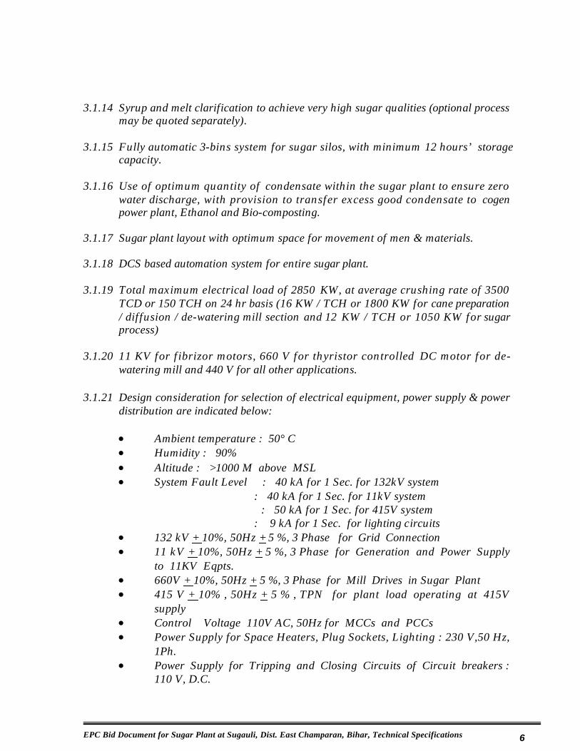
3.1.14 Syrup and melt clarification to achieve very high sugar qualities (optional process may be quoted separately).
3.1.15 Fully automatic 3-bins system for sugar silos, with minimum 12 hours’ storagecapacity.
3.1.16 Use of optimum quantity of condensate within the sugar plant to ensure zero water discharge, with provision to transfer excess good condensate to cogenpower plant, Ethanol and Bio-composting.
3.1.17 Sugar plant layout with optimum space for movement of men & materials.
3.1.18 DCS based automation system for entire sugar plant.
3.1.19 Total maximum electrical load of 2850 KW, at average crushing rate of 3500 TCD or 150 TCH on 24 hr basis (16 KW / TCH or 1800 KW for cane preparation / diffusion / de-watering mill section and 12 KW / TCH or 1050 KW for sugar process)
3.1.20 11 KV for fibrizor motors, 660 V for thyristor controlled DC motor for de-watering mill and 440 V for all other applications.
3.1.21 Design consideration for selection of electrical equipment, power supply & power distribution are indicated below:
x Ambient temperature : 50° Cx Humidity : 90% x Altitude : >1000 M above MSLx System Fault Level : 40 kA for 1 Sec. for 132kV system
: 40 kA for 1 Sec. for 11kV system: 50 kA for 1 Sec. for 415V system
: 9 kA for 1 Sec. for lighting circuits x 132 kV + 10%, 50Hz + 5 %, 3 Phase for Grid Connectionx 11 kV + 10%, 50Hz + 5 %, 3 Phase for Generation and Power Supply
to 11KV Eqpts.x 660V + 10%, 50Hz + 5 %, 3 Phase for Mill Drives in Sugar Plantx 415 V + 10% , 50Hz + 5 % , TPN for plant load operating at 415V
supplyx Control Voltage 110V AC, 50Hz for MCCs and PCCsx Power Supply for Space Heaters, Plug Sockets, Lighting : 230 V,50 Hz,
1Ph. x Power Supply for Tripping and Closing Circuits of Circuit breakers :
110 V, D.C.

EPC Bid Document for Sugar Plant at Sugauli, Dist. East Champaran, Bihar, Technical Specifications 7
x Power will be generated at 11KV, 3Ph, 50Hz with Steam Turbine. Power will be stepped up to 132KV for Grid Connection and Evacuation to BSEB
x 11kV power supply will be given to Sugar Plant Switchboard. Further downstream power distribution will be done in Sugar Plant
x 11kV/433V distribution transformers are provided to cater power to 415V rated equipments in plant
x 230 V Single phase power supply shall be derived through Phase & Neutral for single phase power consumer
3.2 Scope of Supply
3.2.1 General
The scope of work will include design, engineering, manufacture / procure, supply, erection and commissioning of equipment, associated systems, internal electrical distribution system and associated civil works for the entire sugar plant, as detailed hereunder for achieving the guaranteed performance parameters specified for each section and for steam & power consumptions. The Contractor wi l l a lso need to complete al l associated electr ical , mechanical and instrumentation work required for installation, commissioning of the entire equipment, and proving the performance at site.
The contractor will also be responsible for dismantling of all defined existing buildings & structures at site, prior to installation of equipment under the scope.
The Contractor will be responsible for providing an efficient, reliable and state of art technology equipment. The specifications in this section, attempt to define the scope and specifications. However, the onus of providing the appropriate equipment and auxiliaries for successful commissioning, performance proving and operation, entirely rests with the Contractor.
The scope of work for the equipment, associated systems and civil works covered under the specifications will include, but not limited to the following.
(a) Design, engineering, supply, fabrication, manufacture, assembly, shop tes t ing and inspect ion at manufacturer's works , erect ion and commissioning
(b) Providing all labourers, materials and equipment for testing at shop / site,as required.
(c) All spare parts required for the commissioning.

EPC Bid Document for Sugar Plant at Sugauli, Dist. East Champaran, Bihar, Technical Specifications 8
(d) Spare parts required for two (2) years of trouble free operation
(e) Special tools and tackles required for operation and maintenance, inspection, and repair of the equipment / systems offered.
The specifications are intended to cover the design, engineering, manufacture / procure, supply, erection, testing and commissioning of entire sugar plant equipment, associated systems, electrical distribution system, necessary piping / supports / valves / instruments, DCS based control & instrumentation system, necessary structures and civil works.
Supplies and services shall be rendered in conformity with proven engineering principles, taking into account the current state of the art technology. The requirements of the contract must be fulfilled in its entirety.
The supplies and services within the scope shall be rendered inclusive of all appliances and interconnecting arrangements with other supplies, necessary for installation of all accessories and for satisfactory operation, maintenance and repair.
The scope of supply and services shall include all necessary work and supply of equipment and material whether mentioned in these specifications or not, but which are necessary for the satisfactory, reliable, safe operation, maintenance and required for achieving guaranteed performance parameters.
Any equipment, devices or material even if not included in this EPC bid, but found necessary for the safe and satisfactory functioning of the unit under this EPC bid, shall be supplied, erected and commissioned by the Contractor at no extra cost to the Owner, as though, such equipment, material or work were originally specified and formed part of the scope of work.
3.2.2 Major Equipment
(a) Weigh bridges, cane un-loading & handling arrangements, cane feed tables, cane carriers, preparatory devices like cane flow stabilizer & density enhancer, cane cutter, swing hammer type heavy duty cane fibrizor, rake cane carrier, auto cane feed control system, DSM screens for raw juice, etc.

EPC Bid Document for Sugar Plant at Sugauli, Dist. East Champaran, Bihar, Technical Specifications 9
(b) Cane diffusion process including efficient standard vertical head stock type de-watering mill equipped with 3 rollers type GRPF, Donnelly type chutes, rake type intermediate carriers and drive arrangements, DC motor for mill drive with thyristor converter station, mill gearing trains, open gear and pinion, perforation like lotus for mill and GRPF rollers except top roller, remaceration juice equipment and mixed juice pumps, water flow meter for imbibitions water, hot water imbibitions pumps, automatic imbibitions water flow and temperature control system, mill house crane & gantry, etc.
(c) Cane diffuser and all accessories like bed plate, enclosure, feeder drag conveyor, slide gates, side and end wall panels, juice collecting trays, juice scalding process equipment, perforations on fixed bottom screens, loosening screws for moving bagasse mat, counter current extraction, un-screened & screened juice pumps, self rotating drum press, de-juicing rake inter carrier with perforated bottom and trough, de-watering mill, milk of lime dosing system, chain cleaning & greesing arrangement, re-circulation remaceration juice pumps, lagging & cladding, drives for various accessories, automation & instrumentation, etc.
(d) On-line mass flow meters for mixed juice, juice heaters, sulphur furnace, air blowers, juice & syrup sulphiters, sulphur burning furnace, air blower fans, juice sulphiter and automatic pH control system, milk of lime preparation, clarifier and vacuum filters, juice evaporator station with quintuple effect evaporator and extensive vapour bleeding, on-line conductivity measurement, syrup and molasses storage tanks, molasses conditioning units, automatic brix and temperature control system, batch type vacuum pans with automation, seed and vacuum crystallizers, condensers, injection and spray water pumps, spray nozzles and pond, etc.
(e) Crystalizers, fully automatic flat bottom type centrifugal machines for A massecuite, continuous centrifugal machines for B & C massecuite, transient heaters, hot monorail crane, pug mills & magma mixers, air compressor & magma pumps, sugar melter, DSM screen and dry seed conveyor, automatic brix and temperature controller for sugar melter, dry seed conveying system, etc.
(f) Grass hoppers, sugar elevator, sugar grader, sugar dust catcher, fully automatic sugar silo and weighing machines, molasses weighing scale, final molasses and hot / cold water tanks, sugar go-downs, ground water conservation and re-circulation system, etc.
EPC Bid Document for Sugar Plant at Sugauli, Dist. East Champaran, Bihar, Technical Specifications 10
(g) Miscellaneous equipment including pressure reducing and de-superheating systems, headers and valves, bagasse baling machines, all juice / vapor / massecuite / steam / water / condensate pipelines along with all accessories / supports / instrumentation, insulation & lagging, DG set for emergency power, effluent treatment plant.
(h) All steam and power consumption reduction equipment for achieving the related guaranteed performance parameters.
(i) Water supply & distribution equipment for 6000 KL / day capacity including jack well, pumps, piping up to main water storage tank, distribution header outside the storage tank, including all accessories, supports, etc.
3.2.3 Electrical Distribution System
All internal electrical distribution system within the sugar plant for 11 KV, 660 V and 440 V systems including power & control cables, accessories, earthing & lightening protec t ions , a l l mandatory safety devices, instrumentation,illumination, etc. will be included in the contractor’s scope.
3.2.4 Control & Instrumentation
All necessary control & instrumentation equipment for efficient operation of the proposed sugar plant equipment, associated systems and electrical distribution system or otherwise for the entire sugar plant, will be in the scope of the Contractor.
3.2.5 Civil Works
All necessary civil works including foundations, structural, earth work, etc. required for installation of the proposed sugar plant equipment, associated systems and electrical distribution system will be in the scope of the Contractor. The Contractor to arrange for local statutary requirements / approvals for civil structures / buildings.
3.3 Services
3.3.1 Design and Engineering
(a) Preparation of design calculations and detailed drawings
(b) Preparation of BOQ
(c) Preparation of manufacturing drawings

EPC Bid Document for Sugar Plant at Sugauli, Dist. East Champaran, Bihar, Technical Specifications 11
(d) Preparation of quality assurance and inspection plans and implementation schedule.
(e) Preparation of schedule for site testing and commissioning.
3.3.2 Erection & Commissioning
(a) Inspection of civil work in foundations, trenches and allied jobs.
(b) Unloading, unpacking, shifting to locations, positioning, aligning and fixing of equipment which are included in contract
(c) Pre-commissioning checks.
(d) Commissioning , testing and trials runs and performance proving
(e) Completion of documentation and records.
3.3.3 Statutory Approvals
(a) Obtaining approvals and all licenses on drawing and designs from local authorities, as required.
(b) Arranging inspections and approvals for commissioning of plant electrical from Local authorities and Chief Electrical Inspector.
(c) Obtaining permission from Irrigation Department, Govt. of Bihar for lifting required quantity of water, as well as required permissions from agencies like road, PWD, railway, etc. for laying the line
3.3.4 Inspections / Review Meetings
(a) Making the arrangements for periodical and final inspection of all major equipment at own or sub-contractor’s works.
(b) Attending the periodical review meetings at site or at the agreed locations.
3.4 Terminal Points
3.4.1 Sugarcane
At the weigh bridge inlet of the cane carrier

EPC Bid Document for Sugar Plant at Sugauli, Dist. East Champaran, Bihar, Technical Specifications 12
3.4.2 Raw water
At the specified intake point at the nearby Gandak river
(Contractor’s scope covers suitable water lifting scheme, pumps, pipelines, valves / fittings, ground water reservoir, common distribution header, raw water reservoir, raw water transfer pumps & accessories, pipeline from reservoir up to sugar plant and internal water distribution, including all fittings / supports / valves, etc. for 6000 m3/day water supply / storage / distribution. The Contractor also to arrange water supply from bore wells at defined locations and storage facility for 8-10 days).
3.4.3 Screened & Mixed Juice
At the discharge end of juice mass flow meter (after proportioning device & juice transfer pumps, including valve), located in the diffusion section, for transfer of 50-55% of juice to ethanol plant (balance 50-45% of juice to be transferred to sugar process house by the Contractor).
3.4.4 Steam supply
At the LP header of cogen power plant located at 1.5 m level beside the powerhouse building, towards the sugar plant side.
(Contractor’s scope covers LP steam pipeline from LP header of cogen power plant up to sugar plant and internal distribution pipelines, including all flanges, valves, accessories, supports, etc.)
3.4.5 Power supply
At 2 nos. 11 KV feeders identified in 11 KV switchboard in cogen plant TG building.
(11 KV (UE), XLPE insulated aluminium conductor cables from cogen power plant up to the sugar plant, 11 KV incomer panel & switchboard for cutter / fibrizor motors to be located suitably, related protections including VCB panel, etc., 11 KV network near main gate for power supply to colony, 11 K V / 440 V distribution transformers and 440 V internal power distribution system including related panels / switchboards / starters / cables / protections, 11 KV / 690 V converter transformers, thyristor control panels and related distribution system including panels / switchboards / starters / cables / protections, etc. for DC motor & all earthing will be in the contractor’s scope).

EPC Bid Document for Sugar Plant at Sugauli, Dist. East Champaran, Bihar, Technical Specifications 13
3.4.6 Compressed air
Necessary size compressor & accessories, distribution header & pipelines, valves, fittings, etc. required for the sugar plant included in the contractor’s scope.
3.4.7 Consumable such as Lime, Sulphur & Chemicals
Quicklime powder / liquid and phosphate at the storage sheds suitably located in the sugar plant. Sulphur powder at the sulphur shed suitably located in the sugar plant.
3.4.8 Imbibition Water
At the discharge valve of hot water overhead tank of condensate water in the sugar process house (entire hot water circulation pipelines, pumps, accessories included in the Contractor’s scope).
3.4.9 Bagasse
At the discharge chute of the bagasse elevator
3.4.10 Molasses
At the delivery header of the molasses transfer pumps, near the molasses storage tank located in sugar plant.
3.4.11 Condensate
At the outlet header of condensate transfer pumps, including valve, located in the sugar process house.
3.4.12 Filter Cake
At the discharge chute end, below the vacuum filters
3.4.13 White Plantation Sugar
At the outlet of sugar stacker in the sugar go-downs
3.4.14 Effluent
Up to one point in the nursery plantation area, treated effluent meeting the BSPCB norms.
EPC Bid Document for Sugar Plant at Sugauli, Dist. East Champaran, Bihar, Technical Specifications 14
3.4.15 Civil Works
Entire civil works & structural in the sugar plant area along with civil works for jack well, foundations for pumps / distribution pipelines, water storage tank, bore wells, etc. will be in the Contractor’s scope. Also, the demolishing of all existing structures / buildings at site and removal of all debris at the entire site will be in the Contractor’s scope(for all the upcoming plants, about 65 – 70 acres area).

EPC Bid Document for Sugar Plant at Sugauli, Dist. East Champaran, Bihar, Technical Specifications 15
Chapter – 4
Technical Specifications
4.1 Cane Un-loading / Loading
4.1.1 Weigh Bridges
The weigh bridges will be pit mounted, fully automatic electronic, load cell type,along with digitized software control. The specifications of required weighbridges will be as under:
Nos. Capacity, MT Platform Size, m x m1 50 16 X 32 30 16 X 33 5 4.8 X 2.4
Weigh bridge units will be along with platforms, suitable compression type load cells, suitable junction boxes, digitizers, screened cables and standard weights for calibration (Contractor to give performance guarantee for two crushing seasonsfor trouble free operation).
4.1.2 Cane Unloading & Handling
Equipment / Machinery Capacity, Nos. & type
Remarks
Cane Un-loading Bridge 2 Nos. 2-motion type Cane Un-loading Gantry 10m lift, 30 m span
& 40 m length According to local situation
Cane Un-loadingtrolleys
5 MT each x 4 Nos. Capacity of cane un-loadingtrolley will depend on the type of cane loading in the vehicles
Lifting crane bar / grab Will depend on loading of cane in the vehicles

EPC Bid Document for Sugar Plant at Sugauli, Dist. East Champaran, Bihar, Technical Specifications 16
The cranes shall be of 2-motions electrically operated, overhead type unloading cranes, conforming to Class IV IS specifications and capable of 20 lifts per hour. In each lift, sling bar shall lift at least 4 MT cane and grab shall lift at least 3 MTcane. The crane shall be complete with its accessories, gantry columns &attendant plat-form, along the length of the gantry on both sides, 2 Nos. cat-ladders, etc.
They shall be heavy-duty type and suitable for continuous outdoor working. All operations shall be electrically controlled from the operator's fixed cabin. The crane gantry span shall be 30 meters. The crane gantry shall be 40 meters in length, with gantry columns 10 meters apart.
The bridges shall be of box type construction made of IS 2062. Gantry columns shall be L shape construction but the 4-end columns should have double L construction at 90 deg. End columns shall be provided with the tie beam on each end.
The applicable design codes will be IS 3177 & 807. All electric motors shall be of crane duty, with T.E.F.C. enclosures suitable for 300 operations per hour and will have following specifications:
Particulars Type of motor k W Rating Duty Hoisting Drum Drive Squirrel cage 20 1 hr. S4Holding Drum Drive Squirrel cage 20 1 hr. S4Long travel drive Slip ring 7.5 ½ hr. S4 Cross travel drive Slip ring 4.0 ½ hr. S4
For operation of these motors, push button type panel shall be provided and its location shall be in the cabin attached to the trolley. The following speeds shall be provided for various motions:
Operation Speed Hoisting 12 meters/minuteHolding 12 meters/minuteLong Travel 15 meters/minuteCross Travel 15 meters/minute
The sling bars and hydraulically operated grabs shall be provided for quick and fast operations, according to local arrangements of loading of sugar cane in vehicles.

EPC Bid Document for Sugar Plant at Sugauli, Dist. East Champaran, Bihar, Technical Specifications 17
The height of the lift shall be 10 meters. All gear boxes shall be totally enclosed, dust proof, helical type gear and shall be designed with a service factor of 2.0. All couplings shall be of flexible gear type with periodically greasing arrangement. All brakes shall be of electro-hydraulic thruster operated type. Ratio of the pulley dia (PCD) to wire rope dia shall not be less than 20. The crane shall be provided with grab attachment. Suitable sheds shall be provided on the trolleys.
Cane Feed Tables
4 nos. cane feeder tables of minimum 6-meters width and 7 meters in length shall be installed at right angle to the cane carrier; two on RHS and two on LHS of cane carrier no. 1.
Each feeder table shall be of all steel construction fitted with 8 strands of 150-mm pitch heavy-duty steel drag type chains having breaking strength of minimum 40,000 kg. The feeder table shall be complete with cast steel sprocket wheel having machine cut teeth (tips of sprockets shall be chamfered sharp for easy engagement even with little misalignment), shafts, bearings etc. The feeder table shall be driven by a 10 kW, VFD AC motor so as to provide speed regulation from 1 to 3 meters/min.
The feeder table shall be suitably supported on steel structure designed to withstand heavy shocks. The tail end shall be located just above the ground level. The slope of table shall be adjusted to discharge all cane vertically to the centre of the cane carrier.
Operator’s common control cabin, to control all tables by a single operator, on a suitable height shall be provided to have a clear view of the loading of the cane carrier. Suitable ladders shall be provided to this cabin.
Cane Carriers & Preparatory Devices
Equipment / Machinery Size & Nos. KW rating Cane carrier-1 1 x 1830 mm x 72” 40Cane carrier-2 1 x 1830 mm x 72” 40

EPC Bid Document for Sugar Plant at Sugauli, Dist. East Champaran, Bihar, Technical Specifications 18
Cane Carrier No. 1:
One cane carrier 1830 mm / 72” wide and horizontal loading length 40 meters shall be provided. The cane carrier shall be installed just above ground level of500 mm clearance. The length of its inclined portion shall be such that it gives an inclination of 18 deg. for the leveller with a minimum length of 8 meters. It shall have three strands of chains of 150 mm pitch IS: 8465. The breaking strength of the chains shall be minimum 40,000 kg. The cane carrier and its structure shall be of all steel construction, the slats 6 mm thick shall be as per IS: 8236 and fastened to chain by bolts and check nuts.
It shall be driven by 40 kW with constant torque characteristic and operating speed range. The VFD motor with AC variable frequency with panel shall be directly coupled to helical gear box with open gearing to provide 3 to 7 m/minute variable speed.
Cane flow stabilizer shall be installed on the first cane carrier. The rotary cane magnet shall be installed on the discharge chute of first cane carrier. Arrangement for adjusting the clearance up to 1000-1100 mm between the tip of CSDE knives and the slats shall be provided. 3 nos. of machined packing shall be provided for the foundation frames of CSDE, gear box and motor.
Cane Carrier No. 2
One cane carrier 1830 mm wide shall be provided. The length of its inclined portion shall be such that it gives an inclination of 18 deg. for the cutter with a minimum length of 8 meters having a slope of not more 6 deg. before fibrizer. It shall have suitable elevation to suit the installation of fibrizer. It shall have three strands of chains of 150 mm pitch IS: 8465. The breaking strength of the chains shall be minimum 40,000 kg. The cane carrier and its structure shall be of all steel construction, the slats 8 mm thick shall be as per IS: 8236 and fastened to chain by bolts and check nuts.
It shall be driven by 40 kW VFD AC motor with constant torque characteristic and operating speed range. The VFD motor with AC variable frequency panel shall be directly coupled to helical gear box with open gearing to provide 3 to 7 m/minute variable speed.
The cane cutter shall be installed on the cane carrier no. 2. The cane fibrizer shall be installed on the head of cane carrier no. 2.

EPC Bid Document for Sugar Plant at Sugauli, Dist. East Champaran, Bihar, Technical Specifications 19
The carrier frame work of mild steel plate extending along the complete length of the carrier shall be not less than 6 mm thick except at the place of cane flow stabilizer and density enhancer where the thickness should be 10 mm for about 2500 mm length. Stainless steel cladding of 4 mm thick plate shall be provided in the working portion of side plates of cane carrier near CSDE and cane Cutter.
The framework shall be adequately stiffened at the top and bottom by angle iron welded to the side plates. The side plates shall be bolted to and supported by rolled steel 250 mm x 75 mm channels or sections of equivalent strength and be provided with base plate of ample area reinforced by gusset plates of angle plates. Four foundation bolt holes would be provided in each base plate. The columns in the immediate vicinity of the cane knife sets shall be 250 mm x 75 mm double channels. All the Columns at drive end should be adequately braced by angle cross pieces of heavy section secured by gusset plate and bolts or by welding.
Three longitudinal 150 mm ISMB runners with renewable 10 x 65 mm thick spring steel wear pads would be bolted on the top side of the cross pieces to support the cane carrier chain rollers. The distance between the adjacent supporting columns should not exceed 3.50 meters. The runners would be lowered slightly where the chain arrives at and leaves the runners. 8 mm x 75 mm spring steel flat should be tack welded on the side plates of the cane carrier so that cane carrier slats touch the flat iron only to avoid wearing on side plates.
The return side of the apron shall be supported on idler pulleys of 60 m/m width, 280 mm dia with 75 mm dia of 40C8 shaft running in anti-friction bearings, housed in the cast steel pedestals, with grease cup one each for each bearing.
The carrier chain driven by means of cast steel sprockets having machine cut teeth (fully chamfered at tips) at least 16 in number and mounted on minimum 250 mm central dia. head shaft of 40 C8 quality and shall run in 200 mm size spherical roller bearings housed in the cast steel Plummer blocks.
The columns under the head shaft and carrier drive shall be of extra heavy section to withstand vibrations. At the non-driving end of the cane carrier, the chain shall be mounted on cast steel sprockets having machine cut teeth on minimum 140 mm central dia tail shaft of 40 C8 quality running in minimum 120 mm size spherical roller bearings housed in the cast steel Plummer blocks and slide rails with tension bolts for tightening the chain. The margin for tensioning the chains shall be of 325 mm.
EPC Bid Document for Sugar Plant at Sugauli, Dist. East Champaran, Bihar, Technical Specifications 20
The head and tail shaft shall be hot forged and ultrasonically and tested with magnetic particle tests. Rotary brushes to be provided on the head shaft of cane carrier to clean slats and chains to remove cush-cush and dirt from the carrier chain
Rotary Cane Magnet
A rotary cane magnet shall be installed in the discharge chute of cane carrier no. 1 the angle of discharge chute shall be 800 to horizontal plane. The effective width of the drum of the rotary magnet shall be of not less than 2000 mm. The dia of magnet drum shall be of 1200 mm.
The pick up capacity of magnet shall be of 200 kg tramp iron pieces. The electromagnet capacity shall be of 15 kW. The rotary magnet shall be driven by the suitable sprockets and roller chain mounted on the head shaft of the cane carrier no. 1.
4.2 Cane Preparation
4.2.1 Cane Flow Stabilizer & Density Enhancer (CSDE)
One no. CSDE set having not less than 32 knives secured to cast steel hubs of IS: 1030 grade 280 – 520W mounted on a forged steel shaft of 200 mm dia. of 40 C8 qualities. The dia. over the tips of knives shall be not less than 1600 mm. The knife shaft shall be supported at 1600 mm bore, heavy duty self aligning double row spherical roller bearings with adopter sleeve in the cast steel plummer blocks. The knives shall be of special cross edges, special shock resisting steel having hard faced cutting edges, hardness 45 to 48 HRC and tenoned into the hubs eliminating the shear on the bolts which should be of EN8 steel with nut bolts and check nuts. The knives shall conform to IS: 8461. A suitable fly wheel of CI grade FG 260, IS – 210 duly machined and well balanced shall be provided at the outer end of the shaft.
The CSDE set shall be driven by a continuously rated drip proof/screen protected slip ring motor of 90 kW and 1440 rpm synchronous speed at a total slip of 15 percent. It shall be coupled through suitable helical gearbox having service factor not less than 2.0 by means of geared coupling, also having service factor of 2.00, to get final speed of 288 RPM capable of transmitting 90 kW continuously. The motor shall be complete with starter (current not exceeding 300% of FLC) and suitable buffer resistance.

EPC Bid Document for Sugar Plant at Sugauli, Dist. East Champaran, Bihar, Technical Specifications 21
The knife set of CSDE shall be installed on the horizontal portion of the carrier and clearance in between the slats and Knives tips shall be maintained as 1100 mm The knife set shall be totally enclosed by suitably reinforced hood of 10 mm thick and mild steel plate attached to the cane carrier frame work and provided with suitable swing flaps and bolted doors at top of the hood to suit reverse rotation. The hood cover shall be extended towards the cane yard at least 4.00 m from the centre of CSDE. Stopper of suitable size having clearances of 25 mm shall be fitted on the top of CSDE to restrict overriding of cane pieces.
4.2.2 Cane Cutter
One no. cane cutter set having not less than 48 knives secured to cast steel hubs of IS: 1030 Grade 280 – 520W mounted on a forged steel shaft of 250 mm dia. of 40 C8 quality. The dia. over the tips of knives shall be not less than 1600 mm. The knife shaft shall be supported at 200 mm bore, heavy duty self aligning double row spherical roller bearings with adopter sleeve, housed in the cast steel plummer blocks. The knives shall be of special shock resisting steel having hard faced cutting edges, hardness 45 to 48 HRC and tenoned into the hubs eliminating the shear on the bolts which should be of EN8 nut bolts and check nuts. The knives shall conform to IS. 8461
A suitable fly wheel of CI grade FG 260, IS - 210 duly machined and well balanced shall be provided at the outer end of the shaft.
Cane cutter set shall be driven by a continuously rated drip proof / screen protected slip ring motor of a 250 kW and 600 RPM, AC 11 kV synchronous speed at a total slip of 15 percent.
The motor shall be complete with starter (starting current not exceeding 300% of FLC) with suitable buffer resistance. It shall be directly coupled by geared coupling, having service factory of 2.00, capable of transmitting 250 kW continuously.
The knife set shall be installed on the inclined portion of the cane carrier no. 2 and be provided with a suitable device for adjusting clearance in between the knives tip and slats from 25 to 150 mm. The knife set shall be totally enclosed by suitably reinforced hood of 10 mm thick and mild steel plate attached to the cane carrier frame work and provided with suitable swing flaps and bolted doors at top of the hood.

EPC Bid Document for Sugar Plant at Sugauli, Dist. East Champaran, Bihar, Technical Specifications 22
4.2.3 Swing Hammer Type Heavy Duty Cane Fibrizer
Swing hammer type heavy duty cane fibrizer shall be located at the head end of cane carrier no. 2, to suit 1830 mm wide cane carrier having not less than 160 hammers. Weight of each hammer shall be not less than 20 kg. The hammer shank shall be 50 mm thick minimum.
The fibrizer should have detachable hammers made up of Boiler quality alloy steel shank IS: 2002 - 1962 Grade 2-B of special shock resistance alloy steel, hard faced, by L& T-6006 hard facing electrodes to 600 BHN and secured through 50 mm dia En 24 alloy steel pins, the hammer shank and fibrizer disc should have GM bushes to suit En 24 pins. 50 mm hubs shall be of CS forged steel fitted on rotor shaft. Deflector plate of 20 mm thickness with 4 mm S.S. lining shall be provided.
The rotor shaft shall be heavy duty minimum 400 mm dia at the hubs and 260 mm dia. at the bearing journals and shall be 40 C8 steel as per IS: 1570.
Anvil plate shall be of pocketed design, having wrap angle of 150-deg. The base plate thickness of the anvil shall be minimum 25 mm. Hard facing on the anvil working surface shall be having minimum hardness 600 BHN. Anvil plate shall have provision for adjusting the anvil clearance. A suitable long radius, guide floating flap of 20 mm thick, having dead weight balancer, shall be provided at the entry point of anvil.
Rotor shall be supported on two heavy duty self aligning double row spherical roller bearings. Bearing shall be mounted on shaft with adapter sleeve. Tip dia. of hammers shall have 1830 mm [swing dia] when running at 750 rpm.
The fibrizer rotor shall be completely covered by reinforced mild steel fabricated hood made out of 12 mm thick plate attached to the cane carrier frame work and will be complete with deflector plate, adjustable mild steel fabricated anvil plate, anvil suspension gear, front adjustable cover, rear chute of 12 mm thick with 4 mm thick SS lining on side plates and guide plate, bolted doors on the top of the hood.
Rotor bearing plummer blocks shall be cast steel. Pressure oil lubricating system for bearings shall be provided with 2 nos. pumps, 2 nos. coolers (one each as standby) oil reservoir, pressure gauge, piping, return line, needle valve fitting etc. with provision for auto start of standby pump on LP oil. The working speed of SKF spherical roller bearings chosen shall be not less than 750 rpm with grease lubrication and 800 rpm with the oil lubrication (must follow the speed recommendations of original manufacturer of SKF Sweden bearings).

EPC Bid Document for Sugar Plant at Sugauli, Dist. East Champaran, Bihar, Technical Specifications 23
The PI shall be 92-94% on pol basis should be achieved throughout the season without stoppage for any maintenance work.
Drive for Fibrizer
Swing Hammer type heavy duty Cane Fibrizer shall be driven by 11 kV AC motor with 750 rpm and rated power of 1500 kW.
Cane fibrizer shall be driven by a continuously rated drip proof / screen protected slip ring 11 kV AC motor of 1500 kW having speed 750 rpm. The AC motor will be designed to 11 kV synchronous speeds at a total slip of 15 percent. Motor shall be directly coupled by geared coupling capable of transmitting 1500 kW on one end continuously. The motor shall be complete with starters (starting current not exceeding 300% of FLC) and suitable buffer resistance.
4.2.4 Rake Cane Carrier
Rake type conveyor to be installed after fibrizer shall be of a steel construction having suitable width trough to accommodate 1830 mm rake width and of suitable length to suit minimum feeding height. The tail shaft centre of rake carrier shall be in line with head shaft centre of cane carrier. The rake carrier and its structure shall be of all steel construction with two strands block type forged steel chain of 229 mm pitch, having 60,000 kg breaking strength having locking arrangement with check nuts. Flights would be made out of 10 mm thick mild steel plate of suitable shape and profile and welded on pipe construction slats. The slats shall have suitable arrangement for fitting with the chain attachment at every third link with the help of bolts and check nuts.
The rake cane carrier should have runners of channels angle iron with 10 x 65 mm wear flats and 10 mm thick mild steel bottom trough plate with stiffeners and should be supported on steel channel columns of adequate strength provided with rigid base plate. Stainless steel liner of 4 mm thick plate shall be provided in the bottom trough of the rake cane carrier. The columns should be adequately braced to avoid vibrations. The elevator chain shall be driven over two cast steel sprockets having minimum 14 machine cut teeth (chamfered sharply at tips), mounted on 175 mm central dia. head shaft of 40 C8 qualities running in minimum 140 mm size anti friction spherical bearings housed in the cast steel pedestals secured to head shaft columns.

EPC Bid Document for Sugar Plant at Sugauli, Dist. East Champaran, Bihar, Technical Specifications 24
The tail shaft of minimum 140 mm central dia 40 C8 quality should have two cast steel sprockets having 14 machine cut teeth (chamfered sharply at tips) to guide the chains and would run in minimum 120 mm size spherical roller bearings housed in the cast steel plummer blocks - pedestals attached to the rake carrier boot. The portion of the chain below the fibrizer shall be suitably covered to avoid damage due to prepared cane thrown by the fibrizer. The tightening arrangement shall also be provided near the centre of carrier in vertical direction by providing idler sprockets. The margin of tensioning shall be 750 mm in the direction at right angles of chain.
Rake Cane Carrier Drive
Rake cane carrier - 25 kW VFD Motor driveSpeed of Rake cane carrier - 7 to 25 meters/minute variable
The rake cane carrier drive shall have a constant torque characteristic over operating speed range. The motor with AC variable frequency panel shall be directly coupled to helical gearbox having service factor of 2.0 with open gearing to provide desired speeds.
4.2.5 Auto Cane Feed Control System
The automatic cane feeding control system shall be installed on cane carriers. The system shall ensure the uniform feed rate to the diffuser with provision to change the feed rate at any time having a variation not more than ± 5 % set rate. First cane carrier shall follow speed of secondary cane carrier in a fixed ratio. Load of all cane preparation devices shall override the speed signal of each cane carrier. When load of any cane preparation device exceeds 80% of rated load, the speed of that cane carrier shall be proportionately reduced. If load exceeds 100% of rated load, that cane carrier will stop. It will restart automatically when overload condition on that cane preparation device becomes normal. These overload settings shall be adjustable from the control panel. The system shall have the following provisions.
Sensors:
The load sensing of cane preparatory devices such as CSDE, cutter & fibrizer, shall be done with suitable current transformers / two wire electronic analogue pressure transmitters with capacitance sensing technology with 4-20 mA DC output and configurable for calibration to the required pressure ranges within the designed pressure span of the transmitter. In addition to this level sensing of prepared cane at diffuser shall also be considered.

EPC Bid Document for Sugar Plant at Sugauli, Dist. East Champaran, Bihar, Technical Specifications 25
Control Action:
The system should be provided with two control actions i.e. proportional and ON-OFF control actions. Proportional control shall be as per the diffuser load. ON-OFF control shall be as per the high load settings of the cane preparatory devices and diffuser.
Set Points:
Following settings will be provided,
1. For loads of various cane preparatory devices and diffuser precision load setters of 1 K 10 Turns helipots with dial knobs.
2. For average height and feed rate precision 10 K 10 Turns helipots with dial knobs.
Visual Indication:
Colored lamp indicators shall be provided for the high set load values.
Carrier Speed Adjustments:
The speed of the cane carriers can be adjusted from zero to the rated RPM with the settings provided on the control panel at operators’ console.
Indicators:
Analogue load indicators (i.e. current or pressure indicators) and speed indicators shall be provided.
Power Supply:
230 V AC, 50 Hz

EPC Bid Document for Sugar Plant at Sugauli, Dist. East Champaran, Bihar, Technical Specifications 26
4.2.6 DSM Screens RJ
Machinery & Equipment Specifications Qty.
DSM Screen for Raw Juice (RJ)
2.134 m Width & 0.70 mm Slit
3-Numbers
Each screen shall be of stainless steel stationary wedge bar type having 450 slope, complete with all necessary fittings. All screens shall be mounted on suitable staging by on the rake cane carrier no. 2 at the elevated position to achieve gravity discharge of juice and wet cush-cush and shall be provided with attendant platform. The back side plate of juice box shall be left wide open to achieve manual brushing of the screens to keep underneath the wedge wire gaps free from formation and growth of Leuconostoc Mesenteroides Microbial.
4.3 Cane Diffusion
Cane diffusion process only shall be considered to achieve juice pol extraction above 98.50%. Broad specifications are given in the following paragraphs. However, the Tendererss are free to make minor changes in the specifications to achieve guaranteed performance parameters, based on the proven performance achieved by the i r t echnology / equipment supp l iers hav ing patented specifications. The cane diffusion process will envisage, one de-watering mill after the cane diffuser.
4.3.1 De-watering Mill
Installation of vertical head stock and three roller type mill of 915 mm pc dia. x 1830 mm length (36”x72”), with 3-rollers GRPF, as a dewatering mill.
Each mill roller shall be having minimum nominal shell pc dia. of 915 mm x 1830 mm length and journals of minimum 480 mm dia x 630 mm length and journal centre distance of minimum 3000 mm. The rollers shall be of coarse grain cast iron having hardness 180 -210 BHN. The composition of the shell material shall conform to IS: 1985 and shall be:
Sr. No. Element % composition1. Total carbon 3.20 to 3.60% 2. Manganese 2.20 to 3.20%3. Silicon 1.20 to 2.20%4. Phosphorus 0.50% Max5. Sulphur 0.15% Max
EPC Bid Document for Sugar Plant at Sugauli, Dist. East Champaran, Bihar, Technical Specifications 27
The cast iron shell shall be hot shrunk on forged steel shaft of 40C8 quality conforming to IS: 1570 having a minimum tensile strength of 58 kg/sq.mm. All the shafts shall have square ends, not less than 380 mm square. Top roller shall be fitted with stationary flanges and juice rings in two halves. The bottom roller shall be provided with juice rings and removable guards to prevent entry of juice into the bearings. The cast steel crown pinions shall have minimum 550 mm face width and conform to IS: 2708 Grade 3 having 17 number machine cut teeth, keyed to roller shaft and suitable mild steel guards and troughs.
The headstocks shall be of cast steel as per IS: 1030 grade 280/520 W, having standard vertical design and having vertical mill setting facility. The apex angle should be 770 to 800. These will be of king boltless type. Removable gun metal wearing plates on feed side as well as discharge side and with continuous grease lubricating arrangement between top roller bearings and wearing plates shall be provided. The vertical head stock design should be integral and able to accept 3-more GRPF rollers. The pressure chute length shall be very short. The feed roller shall be removable without disturbing pressure feeding device GRPF assembly.
The top and side caps shall be of cast steel as per IS: 1030 grade 280/520 W and shall be securely locked in position for quick assembly. Stainless steel strip of 8 mm thick shall be provided in the side roller bearing face of the head stock. The eccentricity between top roller bearing centre and hydraulic cap centre shall be kept suitably towards the feed side of the headstock preferably by 40 mm.
All roller shells shall be coated with surface roughening electrode material, except mill feed roller. The bearings shall be of cast steel with gun metal and with efficient water cooling arrangement. The top, top bottom and side roller bearing shall be of cast steel housing with renewable gun metal liners as per IS: 318 -1965.
The Bearing housings shall have efficient water cooling arrangement. The top roller bearings shall be interchangeable. Similarly the feed side and discharge side roller bearings shall be inter changeable by their respective bearings.
The mill shall be provided with cast steel trash beam as per IS: 1030 grade 280 / 520W and supported on heavy steel brackets with pivoted journals fitted in the head stocks and adjustable by means of tie rods and fitted with removable cast steel trash plate as per IS: 1030 grade 280/520 w, bolted by high tensile bolts and nuts. Top roller scrapers shall be of floating type. Scrapers for top and discharge rollers shall have renewable cast iron tips.
All mechanical parts of the mill shall be designed for crushing capacity of 3500 TCD and fibre content of 17% on cane.

EPC Bid Document for Sugar Plant at Sugauli, Dist. East Champaran, Bihar, Technical Specifications 28
The mill shall be provided with hydraulic loading system, consisting of hydro-pneumatic accumulator, one for each of the journal of the top roller, one extra as spare and accessories such as pumping set, receiver tank, suitable pressure gauges, remote control panel and roller movement indicator mechanical as well as electronic type . The dia. of the hydraulic ram for top cap shall be minimum 380 mm. The hydraulic system shall be designed for oil pressure of 280 kg/sq.cm.g.
Centralized grease lubrication system having positive displacement pump at about 400 bar pressure having dual delivery lines made of SS 304 x 3.20 mm thick (DIN standard) of 20 mm dia for main line on both sides of the mill with changeover valves, relief valves and distributors with delivery adjustment arrangement with feed line of 10 mm dia SS x 3.2 mm thick provided to the bearings, complete with control panel pressure gauges and audio/visual alarm with suitable timer arrangement for controlling pump operations.
Juice trough under the mill shall be made of 6 mm thick stainless steel 409 M grade plates. The troughs shall be bolted to the headstocks with stainless steel bolts and copper washers. Joint shall be suitably sealed to prevent any juice leakage.
The mill shall be high set so that no part of the juice tank and pump are situated below ground floor level. The mill shall have common gangway on both sides having width not less than 800 mm with gratings and one for bagasse elevator side and one from mill drive platform, along with the necessary cross. One stair case and working platforms shall be provided for the operations, maintenance and washing of DSM screens.
Necessary approach stair cases, platforms and railings shall be provided between diffuser and dewatering mill.
Access from mill platform to rake elevator drive platform with suitable cat ladders shall be provided. All gangways and staircase shall have hand railings.
Three Roller type GRPF (Grooved, Pressure Feed Rollers, one set for de-watering mill)

EPC Bid Document for Sugar Plant at Sugauli, Dist. East Champaran, Bihar, Technical Specifications 29
Cast iron grooved shell of GRPF, having perforations like Lotus, hot shrunk fit , grooved inter-meshing type under feed roller of the same material as that of mill roller having minimum nominal diameter 80% of the mill roller nominal diameter shall be provided. The shafts shall be of 40C8 quality conforming to IS: 1570 and of suitable central dia. and supported by means of continuously grease lubricated gun metal bush bearings of suitable bore.
The GRPF rollers and light duty guide roller shall be driven by separate couplings and tail bars taken out from the final motion bull gearing train. Main DC motor for mill will be common for mill as well as for 3-GRPF pressure feeding device. The surface speed of GRPF rollers shall be about 25-30% higher than the mill roller surface speed.
The GRPF rollers shall have arrangement to adjust the setting in axial direction by plus-minus 35 mm (axis joining centre line of feed and top roller). The pressure chute shall be of shortest possible length.
Donnelly Type Chute
The Donnelly type chute fabricated out of 6 mm thick duly reinforced SS 409 M plates shall be provided for dewatering mill. It shall have arrangements to adjust the blanket thickness from back side. Side plates of chute shall have suitable height transparent sheet to see the level of bagasse.
Suitable indication shall be provided to indicate feed level of bagasse in the chute of dewatering mill. Level sensing device shall have on – off control of intermediate carrier and shall have sequence inter lock.
4.3.2 Rake Type Intermediate Carrier (RIC) after diffuser
RIC after diffuser will be with perforated bottom for good juice drainage.
The width of the rake inter carrier trough shall be suitable to accommodate 1830 mm rake width and its cross section suitable for handling bagasse for 3500 TCD crushing rate with imbibition up to 350% on fibre, fibre of 17% on cane.
The rake carriers shall have runners of channel with 8 mm spring steel wear flat and 8 mm mild steel bottom trough plate with stiffeners and be supported on steel channel column provided with rigid base plate. The columns shall be adequately braced wherever necessary.
The net effective height of Donnelly chute above GRPF of dewatering mill should be of suitable height to suit the set up.

EPC Bid Document for Sugar Plant at Sugauli, Dist. East Champaran, Bihar, Technical Specifications 30
The inclination of rake inter carrier shall be 45 deg max. The tail shaft centre of rake carrier shall be in line with head shaft centre of cane carrier. The rake carrier and its structure shall be of all steel construction with two strands block type forged steel chain of 229 mm pitch, having 60,000 kg breaking strength having locking arrangement with check nuts. Flights would be made out of 10 mm thick mild steel plate of suitable shape and profile and welded on pipe construction slats. The slats shall have suitable arrangement for fitting with the chain attachment at every third link with the help of bolts and check nuts.
The rake inter carrier should have runners of channels angle iron with 10 x 65 mm wear flats and 10 mm thick mild steel bottom trough plate with stiffeners and should be supported on steel channel columns of adequate strength provided with rigid base plate. Stainless steel liner of 4 mm thick plate shall be provided in the bottom trough of the rake cane carrier. The columns should be adequately braced to avoid vibrations. The chain shall be driven over two cast steel sprockets having minimum 14 machine cut teeth (chamfered sharply at tips), mounted on 175 mm central dia. head shaft of 40 C8 qualities running in minimum 140 mm size anti friction spherical bearings housed in the cast steel pedestals secured to head shaft columns.
The tail shaft of minimum 140 mm central dia 40 C8 quality should have two cast steel sprockets having 14 machine cut teeth [chamfered sharply at tips] to guide the chains and would run in minimum 120 mm size spherical roller bearings housed in the cast steel plummer blocks - pedestals attached to the rake carrier boot. The tightening arrangement shall also be provided near the centre of RIC in direction right angles to chains travel, by providing idler sprockets. The margin of tensioning shall be of 750 mm in the direction at right angles of chain.
RIC shall be provided with special perforated bottom plate to achieve efficient juice drainage and juice collection trough. The bottom plate shall be of SS-304 material of 10 mm thickness and strengthened with SS-304 flat bar stiffeners on the bottom side and having divergent hole-perforations of 5 mm at the top face and 8 mm at the bottom face. The ligament of holes shall be of 15 mm. all drained juice shall be collected at the boot of the RIC and lead further to the pump to re-pump and achieve efficient juice remaceration process to achieve high juice-pol extraction and minimize moisture of bagasse leading to the dewatering mill.
Driving Arrangements For RIC
The rake inter carrier drive shall consist of the TEFC VFD AC motor of 25 kW, 1440 RPM with enclosed helical speed reducer, with open gearing, fluid coupling, and common bed frame. The linear speed shall be not more than 20 m /minute.

EPC Bid Document for Sugar Plant at Sugauli, Dist. East Champaran, Bihar, Technical Specifications 31
4.3.3 Mill Auxiliary System
Mill drive (Thyristor Controlled Variable speed, DC Motor Drive)
The mill will have 660 V DC motors with thyristor controllers, with power requirement of 525 KW for mill and 225 KW for GRPF (total 750 KW per mill). The 36”x72” mill shall be driven by continuously rated 750 kW individual D.C. electric motor.
The DC motor shall be forced cooled with air filters SPDP, IP 23 with class V overload duty S1 continuous. The motor base speed shall be 1000 RPM and shall have constant torque characteristics between 20% to 100% base speed and constant power characteristic between 100 to 110% at base speed.
Detailed specifications of the DC motor shall be as under:
Particulars SpecificationsRating Continuous No. of motors 1Motor size, speed, class &duty
750 kW, 1000 rpm, Class V & Duty S1
Over load duty Class VArmature voltage 660 V Field voltage 220 V Protection IP 23 SPDP(force cooled with air filters)Class of Insulation F, Temp. rise limited to class B at continuous
rating Mounting Horizontal foot mountedAmbient Temp. 50 oC
The motor shall be designed for variable speed operations, controlled by the thyristor converter station, and shall have constant torque characteristics down to continuous operating speed of 20% of the rated speed.
ETD for temperature detection of motor winding shall be provided. Thermesters shall be provided for thermal protection of the DC Motor. RTD shall be provided for bearings. Necessary thermester relays & RTD scanner with tripping facility shall be provided in the thyristor panel.
The digital type thyristor Converter Stations for operation and control of the D.C. motor

EPC Bid Document for Sugar Plant at Sugauli, Dist. East Champaran, Bihar, Technical Specifications 32
Converter cubical fabricated from 12 SWG cold rolled steel sheets, free standing, passivated, and painted with anti-corrosive paints.
The cubicle will house all protective switch gear, thyristor modules, regulation circuit, interlocking relays, mounted on passivated plates; the cubicle will conform to IP-30 protection.
All necessary indications, annunciations, controls will be neatly arranged on cubicle front door with neoprene gaskets on all edges of panel. Ventilation openings shall be provided at the top of panel and on side covers by louvers suitably covered by fine wire mesh.
The thyristor drive panel shall be as per following specifications:
Armature converter
Particulars Specifications
No. & rating of DC motorto be controlled
750 kW, 1000 rpm, Class V & Duty S1
Rated DC voltage 660 V Incoming AC supply 11KV / 440 V, 3 phase, 50 Hz
(11KV / 660 V through converter transformer)Torque rating 100% continuous, 150% for 2 hours and 200%
for 1 min, class V, constant for rated full speedType of Thyristor bridge 3 ph, 6 pulse, fully controlled non regenerativeVoltage grade of thyristor 1500 V PIV (approx)
Panel shall be complete with field converters, regulators, tacho feedback, safety protection, (electronic thermal overload, instant O/L , phase seq. Phase loss, field failure ,tacho/ speed loss & earth fault) indication meters, push buttons, switch gears and controls.
Drive bi - directional in operation with field reversal in the speed range of 50% to 100% of speed at constant torque. Speed regulation will be + 1% of base speed at base speed by tacho feedback. The panel will have facility to accept 4 to 20 mA signal for speed setting in auto mode. Speed regulation with armature voltage feed back shall operate in case failure of tacho feed back.
Auto visual window annunciators will be provided. The pressure ventilation system with electric motor driven blower with filter will be provided for panel.The thyristor panels to be supplied along with AC Room to be provided by the Supplier as a turn key job.

EPC Bid Document for Sugar Plant at Sugauli, Dist. East Champaran, Bihar, Technical Specifications 33
Mill Gearing Train
The mill drive shall be coupled through flexible gear coupling to enclosed reduction gear and single stage low speed reduction gearing unit capable of transmitting 750 kW for mill.
The total reduction ratio of the gearing unit should be such that the mill roller surface speed should be of 12.94 m / min (mill roller speed of 4.50 rpm), when motor is run at its base speed.
The enclosed reduction gear box shall have hardened and ground internals and shall have minimum service factor 2.0 with forced grease lubrication system.
The pinion should be of EN-24 and gears of cast steel conforming to IS-2708 Gr III hardness of pinion and gears should be minimum 250 BHN and 220 BHN respectively.
Final Open Gear & Pinion
The open spur gearing shall be designed to transmit 750 kW for mill. The gearing train shall be designed to give continuous rating for mill rollers surface speed of 12.94 m / min; under shock load conditions and shall confirm to IS: 4460-1967. The low speed reduction gearing unit shall have machine cut teeth by gear generating process in both cases. The module of the open gearing should be not less than 30.
Suitable bed plates made in sections, mild steel guards for completely enclosing the gears and pinions (low speed), shall be provided. Shafts of these gears shall be of 40 C8 quality conforming to IS: 1570 having minimum tensile strength of 58 kg /mm² and supported on cast steel plummer blocks with gun metal bearings provided with centralized forced mechanical grease lubrication arrangement with needle valve, standby pump reservoir and return pipe line with auto start of standby pump.
The gearing unit shall be complete in all respects. The mill top roller shall be connected to transmission gear shaft by means of forged steel tail bar of 40 C8 quality conforming to IS: 1570 and two couplings each set. The length of the tail bar shall be not less than 2000 mm.
The margin for normal working lift of the top roller shall be kept 12 mm for the dewatering mill. Two suitable cast steel couplings, one of lesser cross section so as to act as a fuse to safeguard reduction gearing units and drive with provision of greasing for each face under load shall be provided.

EPC Bid Document for Sugar Plant at Sugauli, Dist. East Champaran, Bihar, Technical Specifications 34
Perforations like lotus for all mill & GRPF rollers except top rollers
All GRPF, mill feed and mill discharge rollers of the mill, shall be perforated like lotus rollers to avoid mill juice flooding, achieve efficient juice drainage and improve the mill extraction to the very high level. Suitable juice guard rings shall be fitted for all of these rollers to avoid juice entry to bearings and journals of mill rollers. Such perforations shall not be provided for light duty under feeder roller and top roller.
Provision of Grooving Pitch, Grooving Angles & Roller Surface Arcing
The grooving pitch, grooving angles and roller surface hard facing of mill rollers shall be carried out as under:
Grooving Pitch:
Description Dewatering MillGrooving pitch mm 35 mm
Grooving Angles & Other Details:
Sr.No.
Description Specifications
1. Grooving Angle0 F, T, D for 2-mills Feed: 400, Top: 450, Discharge: 450
2. Hard facing of Rollers All rollers except Mill feed roller3. Hard facin g o f t r a s h p l a t e s &
scrapersAll trash plate and all scraper tips
4. Messchaert grooves Not to be provided5. Chevron grooves Not to be provided
Remaceration Juice Equipment & Mixed Juice Pumps
The juice from dewatering mill shall be collected in individual cylindrical whirler tank with conical bottom of 1500 mm dia and 1300 mm height and made of 6.0 mm thick SS 409 M connected to mill juice trough through 5.00 mm thick SS 409 M gutter. The collected juice shall be pumped and spread on the diffuser before the dewatering pressure feed drum at the outlet end of diffuser.
The mixed juice from diffuser and primary mill shall be sent to the set of DSM screen for screening.

EPC Bid Document for Sugar Plant at Sugauli, Dist. East Champaran, Bihar, Technical Specifications 35
The screened juice shall be collected in a 5 mm thick SS 409 M cylindrical tank of 200 HL capacity. Suitable strained juice pumps (one as stand by) each of 60 m head shall be provided for pumping the 50% screened juice to juice heaters of sugar plant and remaining 50% juice to the Ethanol plant through suitable juice flow meters.
All unscreened and screened juice pumps to have SS bodies, SS impellers and SS shafts. All the juice pumps should have suction and delivery lines of SS 409 M having suitable sizes for crushing rate of 3500 tcd. Long bends having radius of 1.0 m shall be provided for the delivery lines to avoid choking.
Water Flow Meter For Imbibition Water
Imbibition water online mass flow-meter of 100 MT/hr at 100°C capacity shall be provided for the accurate weighment of water.
On line calibration facility for check weighment with prover tank of suitable capacity shall be provided for random checking of imbibition water delivered by mass flow meter without stopping the crushing.
Hot Water Imbibition Pumps
2 Nos. (1 as standby) Hot water imbibition pumps of 100 m3/hr capacity shall be provided.
Automatic Imbibition Water Flow & Temperature Control System
Imbibition water flow will be controlled to maintain a fixed ratio of imbibition water to cane. The desired ratio will be fed through the keyboard and the load on the dewatering mill and brix of LEJ will be measured. The flow of imbibition water will be regulated to maintain the ratio at various loads. If load of penultimate mill and brix of LEJ is below the minimum running level, imbibition water flow will stop.
Sensor :
On-line brix measurement of LEJ with Coriolis density sensor with dual U tube design or single full bore straight tube design having following specifications.
Description SpecificationsAccuracy + or - 0.0005 gm/ccAmbient Temperature effect 0.001 % of nominal flow rate per0 c

EPC Bid Document for Sugar Plant at Sugauli, Dist. East Champaran, Bihar, Technical Specifications 36
Power supply 85-230 V ACHousing NEMA 4X
Load of dewatering mill with two wire electronic analogue pressure transmitter with capacitance sensing technology having 4 – 20 mA DC out put or current transformer out put for recorder and controller.
Sr. No. Equipment Specifications1. Controller Microprocessor based mul t i l oop PID
controller.2. Control Valve It shall be suitable for controlling the flow of
i m b i b i t i o n w a t e r c o n t i n u o u s l y w i t h proportional control.
3. AC Variable Drive Suitable for controlling the speed of the electric motor employed for imbibition water pump.
Imbibition Water Temperature Control System
Description SpecificationsSensor Suitable RTD PT 100 Transmitter Two wire e lectronic analogue type with 4-20 mA DC
outputController Microprocessor based single loop indicating typeControl Valve Suitable for controlling the flow of water in well designed
and fabricated condensate - water mixing arrangement
Mill House Crane & Gantry will be suitable for the de-watering mill
4.3.4 Cane Diffuser
Cane Diffusion Process
The cane diffusion process shall be designed for 3500 TCD/24 hrs or 150 TCHand will be from commercially proven technology / equipment suppliers. The fibre in cane assumed for diffusion process will be 17% on cane. The Preparatory Index (PI) will be 92-94%. The guaranteed performance parameter will be juice pol extraction of minimum 98.5%. Metallurgy shall be designed in such a way that the working life of all components of Diffuser shall be not less than 20 years(The tenderer to provide detailed specifications of the cane diffuser and associated equipment for evaluation, along with the bid).

EPC Bid Document for Sugar Plant at Sugauli, Dist. East Champaran, Bihar, Technical Specifications 37
Automation & Instrumentation, Operations of Diffuser
Full automation and instrumentation shall be done at the diffuser to achieve consistent performance with minimum work force.
All transmitters shall be of the electronic type with a 4-20 mA output. All the controls except actuators shall be electronic solid state type. Actuators shall be pneumatically operated. All controls and actuators shall be interfaced with the control systems through I/P converters and then with the pneumatic Auto / Manual stations which in turn shall be connected to the valves and actuators.
The auto / manual station shall be mounted near the diffuser for use by the operator. In manual mode, the operator shall be able to operate the valves and actuators without the micro processor. Local control shall override automatic / remote controls.
The following PLC (Micro Processor) based closed loop controllers shall be installed:
Cane bed level in the diffuser,Speed of bed (if applicable), Juice pH controller,Juice temperature controller,
The diffuser in the auto mode with the DCS / PLC based controllers shall maintain the process parameters connected to the PC based supervisory workstation, which shall have bar graphic display of all process parameters.
Full day, 24 hours trends shall be made available on colour video for:
Juice flow,Cane level in the diffuser, Flow of imbibition water and other liquids like press juice if taken,
Pneumatic auto / manual stations shall be provided for imbibition water flow and steam flow.
It shall be required that in the event of high bagasse bed level; the cane feed shall be reduced down in proportion of levels desired. In the case of excessive level in the diffuser the prepared cane supply shall be stopped.
There shall be tripping devices of diffuser moving bed in case of jamming of any screw in the bed.

EPC Bid Document for Sugar Plant at Sugauli, Dist. East Champaran, Bihar, Technical Specifications 38
The level transmitters and indicators shall be provided for level of cane bed, liner speed, grease tanks and all juice tank levels.
4.3.5 Bagasse Elevator
One set of 1.80 m width to carry 60 MT/hr bagasse
One steel rake type bagasse elevator of all steel construction of 1800 mm effective width and suitable length (inclination not to exceed 45 deg. with the horizontal) to carry about 60 tones of bagasse per hour and driven by TEFC electric motor of 25 kW through helical speed reducer with open gearing to give a linear speed of 20 meters/minute shall be provided. It shall have two strands of chains of 150 mm pitch. The breaking strength of chains shall be minimum 40,000 kg.
The bagasse elevator chain shall be driven over two cast steel of 40C8 sprockets with machine cut teeth only mounted on 175 mm dia., head shaft running in 160 mm size anti friction spherical roller bearings with adapter sleeves and lock nuts, housed and secured in cast steel plummer block pedestals.
The tail shaft shall have two cast steel sprockets having machine cut teeth mounted on 140 mm central dia. Shaft shall be running in 120 mm size anti friction spherical roller bearings and adapter sleeves and lock nuts, housed and secured in cast steel plummer block housings with side rails and tension bolts for tightening the chain. The head and tail shaft shall be of 40 C8 steel qualities. The bagasse scrapers would rise on the bottom side of the elevator and discharge by means of mild steel chute bolted to head columns into the main bagasse carrier. The trough side and bottom plate shall be of 8 mm thick mild steel.
Sliding screens shall be provided on the elevator for screening the bagacillo. The screening area shall be 7.0 sq.m for the boiling house of 75 TCH capacity. Each screen shall have a blind portion for sliding it in the elevator portion for cleaning and changing the screens while working. Width of each screen shall be not more than 600 mm. The screen shall have punched conical holes having 6/8 mm dia. (top/bottom) size on the surface facing the bagasse elevator. Platform and staircase shall be provided for approaching on both sides of the elevator.
The bagacillo should be extracted and available at the rate of 9 kg/TCH. Suitable bagacillo blower and piping shall be provided accordingly.

EPC Bid Document for Sugar Plant at Sugauli, Dist. East Champaran, Bihar, Technical Specifications 39
4.3.6 Mass Flow Meters
One mass flow meter will be installed for sugar process house & another for Ethanol plant
Sr.No.
Machinery & Equipment Capacity, m3/hr & Head, m
Numbers
1) Juice Mass Flow Meter 100, 60 2 2) Juice Pumps 100, 60 4
(2 in operation & 2stand by)
Each Juice flow measuring system shall have computerized, instantaneous and integrated system, to be installed in screened mixed juice line with check weighment arrangement. Beam scale of suitable capacity to be provided for random verification with suitable capacity MS tank to be kept at a height for gravity flow of juice to recovery tank.
Specifications for each mass flow meter for mixed juice will be as under:
Sr.No.
Description Specifications
1. Type Coriolis Dual U Tube design or single full bore straight tube design.
2. Wet t ed Par t s and connection
Tube, Manifold, and Process flanges in 316 SS welded design, enclosure in SS 304 and should fulfill NACE standard.
3. Accuracy r 0.10% of mass flow rate4. Ambient Temp
Effect0.001 % of Nominal flow rate per0c
5. Repeatability r 0.05% of rate6. Inaccuracy in
Current outputNone
7. Core processor It should be microprocessor based with digital communication having meter diagnostic capabilities and multivariable measurement with 4 wire system between the sensor and transmitter.
8. Outputs i) 4-20 mA for mass flow rateii) 0-1000 Hz frequency for mass flow rateiii) Digital HART for remote configuration
9. Power Supply 85-250 V AC / 24 V DC

EPC Bid Document for Sugar Plant at Sugauli, Dist. East Champaran, Bihar, Technical Specifications 40
Sr. No.
Description Specifications
10. Electrical Connection
¾ inch NPT
11. Electrical Housing
NEMA 4X
12. Temperature Limits
0 to 1000C
13. Indication facilities
Flow rate in TPH; Current hour flow in tones; Last hour flow in tones Separate display for measured liquid during check weighment.
14. Communication Ports
a) RS 232/RS 485 for PC communicationb) Centronic parallel port for printer
On line calibration facility for check weighment with transfer tank of suitable capacity shall be provided for random checking of juice delivered by the mass flow meter without stopping the crushing. Suitable arrangement for preparation, storage and pumping of phosphoric acid solution shall be provided for the sugar plant juice flow measurement. The tank of stainless steel with stirrer, rubber lined, piping of PVC, dosing pump of suitable capacity shall be provided.
4.4 Sugar Process House
(for 50-55% mixed juice on cane or equivalent to 1750 – 1925 TCD on 24 hr basis or 75-80 TCH, conventional Double Sulphitation Process)
4.4.1 Juice Heating & Clarification
Juice Heaters
Juice heaters shall be provided in such a way that heating is done with various vapours to minimize steam consumption as under:
Raw Juice (RJ) heating will be done in three stages,Secondary Juice (SJ) heating will be done in three stages,Clear Juice (CJ) heating will be done in three stages,
Indicative heating surfaces and numbers of juice heaters w i l l be as under(Tendererss may design heating surfaces and number of juice heaters to achieve guaranteed performance parameters).

EPC Bid Document for Sugar Plant at Sugauli, Dist. East Champaran, Bihar, Technical Specifications 41
Description Specifications, nos. x sq. m. Dynamic juice heater 2 x 150 Vapor line juice heater 2 x 150 Direct contact juice heater 12 nos. of suitable sizeClear juice heater 6 x 120
There will be 2 separate sets of quintuple evaporator and the dynamic, vapour line and direct contact juice heaters will be installed accordingly.
One evaporation set will be in operation with extensive vapour bleeding and one set will be always standby to work while one of the sets is under cleaning. All RJ, SJ and CJ will be heated thrice with the vapours, non condensable gases and condensates from the respective evaporator bodies to minimize steam consumption. Heating surface of each juice heater shall be suitable to achieve proper heating divided in three stages.
All dynamic and vapour line juice heaters shall have SS-304 tubes of 16 SWG (1.625 mm) wall thickness. All dynamic and vapour line juice heaters shall be of 16 passes each to minimize pressure drop.
All vertical tubular juice heaters shall be of multiple circulation type, designed to have juice velocity of 1.25-1.50 m/sec max. The body shall be constructed from 16 mm shell, cover plates of 30 mm and top tube plate of 25 mm thk and bottom tube plates of 30 mm thick each.
Arrangements shall be provided to drain of all juice heaters, drained juice to go to separate collection tank along with suitable pump to deliver the drained material to juice sulphiter. The platform shall be provided below the juice heaters for opening the covers, draining and repairs etc. Each juice heater shall have mercury filled 150 mm dial type thermometer in inlet and outlet branch of juice and for the steam chest.
One compound gauge shall also be provided in the steam chest. Tightening bolt T type or eye type shall have individual fixing pin and pitch shall less than 120 mm. The partition plate and header shall be not less than 12.00 mm thick M.S. plate and flexible cord fixing arrangement with self locking system shall be made of 30 sq. mm with dove tail arrangement.
Annealed stainless steel tubes as per AISI-304 of 45 mm outside dia and 1.625 mm (16 SWG) thick shall be used for raw and sulphited juice heaters of dynamic and vapour line type. Ligament of the tubes shall be minimum 12 mm. The length of tubes shall be about 4000 mm.

EPC Bid Document for Sugar Plant at Sugauli, Dist. East Champaran, Bihar, Technical Specifications 42
Dynamic and Vapour Line juice heaters will be made suitable for two vapour passes.
Juice heater shall be provided with individual condensate receiver for exhaust and vapour condensate along with suitable pumps of suitable capacities of 10 cu.m/hr, and suitable delivery head.
Direct contact juice heaters shall be designed and installed according to the temperature rise expected to achieve minimum steam consumption for juice heating.
4.4.2 Sulphur Burning Furnace
Equipment HS, sq. m & NumbersSulphur furnaces (2 working, 1 spare) 50x3
Each sulphur furnaces shall be of continuous type, suitable for burning 50 kg of standard quality sulphur per hour. Each sulphur burner shall have a minimum 0.50 sq.m burning area capacity. All sulphur feeding valve spindles and seat shall be of stainless steel. The melting chamber for sulphur burner shall be made out of 12 mm thick mild steel plate. The combustion chamber shall be 16 mm thick mild steel with refractory lining.
The furnace shall be complete with, water jacketed counter current cooling arrangement for the vertical gas pipe( material for cooler pipe shall be of schedule 80), mild steel water jacketed scrubbers of 16 mm thick, etc. Exothermic heat energy of SO2 gas will be re-used.
Sulphur pipeline from all the furnaces shall be so designed that both juice and syrup could be sulphited from any of the furnaces either singly or jointly. Sulphur pipeline and crosses shall be of Cast Iron conforming to IS 210-1978. Suitable glass lined rubber diaphragm valves shall also be provided. Temperature indicators for indicating temperature of molten sulphur and SO2 gas shall be provided and automatic control for sulphur furnace shall be provided.
Use of Exothermic Heat Energy:
Electrical vaporizer shall be provided for the initial starting of sulphur melting and generation of sulphur dioxide gas. Once the process is started the exothermic heat of gas will be re-used to melt sulphur powder.

EPC Bid Document for Sugar Plant at Sugauli, Dist. East Champaran, Bihar, Technical Specifications 43
4.4.3 Air Blower Fans
Air rotary blower fans, 3 Nos. of 200 cu.m/hr free air delivery capacity each, pressure of 1.25 kg/sq.cm.g (2 working & 1 stand by).
Each Air blower shall be provided with necessary pipe lines, gauges, valves etc arrangement to supply moisture free air (with air refrigeration system) with suitable filter of adequate capacity, air receiver with suitable relief valve etc. All furnaces shall be connected in such a way that any furnace could be worked with either air blower.
4.4.4 Juice Sulphiter & Auto pH Control System
Juice Sulphiter:
One continuous juice sulphitation unit of 115 HL capacity designed as per NSI specifications for a crushing rate of 75 TCH with 115% juice, retention time not less than 7.0 minutes and working height of juice column above the gas distribution not more than 2.0 m. It shall consist of a reaction tank, stack gas recovery tower, one suitable cylindrical receiving tank, and three [one as standby] suitable centrifugal pumps of 82 cu.m/hr, at 60 m head each capable of pumping juice through three juice heaters in series, to the flash tank of the clarifier. The speed of stirrer used shall be around 16 rpm. Design of the unit shall have arrangement for pre sulphitation, pre liming, shock liming and sulphitation. Telescopic valve to regulate the juice level in the sulphiter shall be provided.
The continuous juice sulphitation unit shall be made from 12 mm thick mild steel plate and be complete with milk of lime proportioning arrangement, SO2 gas pipe shall be of CI conforming to IS-210-1978. Line and sparger shall be of SS 316 grade.
The filtrate from vacuum filter station shall also be pumped to Juice Sulphiter.
Automatic pH Control System For Juice Sulphitation
The microprocessor based two loop pH control system shall be considered. Lime dosing into juice sulphiter shall be automatically controlled based on pre-set ratio to juice flow. Lime flow will be measured to give feed back signal to the limedosing control loop. pH of treated juice will be measured and signal given to control speed of sulphur dosing pump in case of thin film type sulphur burner option. Combustion temperature of thin film type sulphur burner will be measured and air vent valve will be adjusted to control operation of sulphur burner. The system shall have following specifications.

EPC Bid Document for Sugar Plant at Sugauli, Dist. East Champaran, Bihar, Technical Specifications 44
Sr.No.
Equipment Specifications Other Arrangements
1. Sensor Ruggedized industrial grade combined pH e l e c t r o d e w i t h automatic temperature compensation. It shall be f ie ld repairable type.
Suitable magnetic flow meter for the measurement of MJ (mixed juice with filtrate) and MOL
2. pH Analyzer
Microprocessor based d e s i g n w i t h L C D disp lay for pH and temperature value with following facilities:
Output : 4 -2 0 m A d c f o r recorder/controllerPower : 230 V ACSupplyMounting : Panel/FieldAlarm : High/LowHousing : NEMA 4XDiagnostic : F o l l o w i n g Diagnostic features feature shall be providedElectronic failureElectrode coatingElectrode breakage
3. Controller Microprocessor based multi loop controller withf o l l o w i n g m a i n facilities:
Cascade con t ro l and se l f tuning Communication port RS 2 3 2 o r R S 4 8 5 f o r P C communication Centronic Parallel port for printer
4. Control Valve
S u i t a b l e f o r controlling the flow of l i m e a n d S O 2
c o n t i n u o u s l y w i t h proportional control shall be provided.
5. Recorder Suitable recorder shall be provided.
4.4.5 Syrup Sulphitation Unit
One continuous syrup sulphitation unit of 45 HL working capacity of NSI design shall be provided, capable to process syrup of 65 deg. Brix, with working height of 1.50 m. of syrup column above the gas distribution, stack gas recovery unit constructed of 10 mm thick mild steel plate complete with SO2
gas absorption arrangement and all necessary pipelines, valves etc.

EPC Bid Document for Sugar Plant at Sugauli, Dist. East Champaran, Bihar, Technical Specifications 45
SO2 pipe and sparger shall be of SS 316 grade, three suitable sulphited syrup pumps of 25 cu.m/h, 30 mH, each (one as standby); grit catchers and one sulphited syrup receiver of suitable capacity with sight and light glasses, inlet, outlet, and equalizing connections shall be provided.
4.4.6 Milk of Lime Preparation
Equipment Capacity & NumbersLime Slaker 500 kg/hr x 1MOL storage, 2.64 HL 100 HL x 2
Lime Slaker:
One lime slaker shall be provided capable of slacking about 1000 kg of quick lime per hour. A Koran flash tank type lime classifier with grit remover or rake type lime classifier and Vibro-screen shall be provided to remove all grit from the MOL. Two milk of lime storage tanks each of about 100 HL capacity] and two pumps (one as standby) plunger type each of suitable capacity of 3.50 cu.m/hr, delivering milk of lime at 20 m head each and two grit catchers common for both pumps.
The slaker shall be of continuous type, driven by electric motor, through suitable reduction gearing arrangement to generate 6 to 8 rpm. The storage tanks shall be made of 6 mm thick mild steel plates and shall be complete with stirrers with independent drive for each tank and connected through girt catchers to milk of lime pumps. Separate gutters shall be provided over the milk of lime storage tanks for the milk of lime coming from the slaker and return milk of lime.
Milk of Lime pipe lines shall be provided up to juice sulphitation with return piping and to mud overflow tank and to condenser outlet.
4.4.7 Juice Clarifier
Equipment Capacity & NumbersClarifier 170 cum & 22’ dia x 1
One number of 6705 mm or 22 feet dia. clarifier of 444-design with four compartments, each compartment to have height of 1524 mm. Each clarifier shall have separate juice and mud outlet from each compartment. The flocculating compartment complete with skimmer and feed well shall be installed separately.

EPC Bid Document for Sugar Plant at Sugauli, Dist. East Champaran, Bihar, Technical Specifications 46
The clarifier shall be made of mild steel plates having following minimum thicknesses:
Sr. No. Part Thickness, mm1. Bottom 8 2. Shell 6 (with stiffeners)3. Tray (intermediate) 8 4. Tray (Top) 6 5. Top Cover 6 6. Flocculating Compartment 6
The continuous clarifier shall be complete with mild steel flash tank and withdrawal boxes, 2 nos. for clear juice and one no. for mud with sleeves, telescope pipes and O-rings, hinge type squeezers, driving mechanism with variable speed drive head with motor consisting of sprocket, chain and drive guards, all inside and outside clear juice piping and mud piping, all valves and pipe fittings etc, and complete with peripheral walkway, angle iron bracket supporting angles, piping for railing, rail support etc; 4 manholes one for each compartment, each manhole to have platform, railing and access ladder; pumps tank with support, insulation material etc.
Mud liquidating pump of 25 cu.m/hr. and 30 m head of CI construction with bronze fittings complete with drive motor shall be provided. Two clear juice centrifugal pumps each of 80 cu.m per hour and not less than 30 m head and SS construction with SS fittings complete with drive motor and suitable column having sight and light glasses shall be provided for pumping juice through clear juice heater to 1st body of evaporator sets. Provision of recirculation of juice in the clarifier shall be also provided. Arrangement of preparation and dosing of flocculent shall be provided.
The centre tube of each clarifier will be made of seamless steel in one piece. The gland portion of sealing rings shall be provided with additional SS – 304 material gland rings having 12 mm thick x 100 mm width duly machined and ground to keep compartments sealed and leak proof.
4.4.8 Rotary Vacuum Filter
Equipment Capacity & NumbersVacuum Filter 36 sq.m Filtering Area (FA), 8’ x 16’ size, 2 nos.
Two rotary vacuum filters shall be installed, each of 2.44 m dia x 4.88 m long drum (8’x16’) having filtering area of 36 sq. m each.

EPC Bid Document for Sugar Plant at Sugauli, Dist. East Champaran, Bihar, Technical Specifications 47
Each rotary cane mud vacuum filter shall have nominal filtration area of 36 sq.m and installed at a height so as to have a operating level of min. 8 meters from factory floor level, shall be complete with 5.00 mm thick SS 304 grade drum, 8 mm thick SS heads with MS structural reinforcement, cast iron trunnions, SS 304 grade internal piping and decking, SS screens, MS trough, agitator, two numbers valves, one on each side consists of bronze valve body, bronze wear plates, washing assembly and scrapper, variable speed drum drive and constant speed agitator drive.
The drum drive shall be of 1.50 kW TEFC motor having means to vary the drum speed from 30 RPH to 10 RPH. The agitator drive shall be of 1.00 kW TEFC motor. The rotary filter shall be complete with two numbers filtrate receivers fitted with gun metal vacuum release assemblies and copper floats, one number vacuum regulating valve, two nos, filtrate pumps each capable to extraction 85 cu.m / hr (one as standby) filtrate under vacuum of 500 mm (20’’) mercury and discharging at 20 meters head, one cascade condenser, one entrainment separator with sealing arrangement to discharge the entrained juice to mud receiving tank, feed mixture, one vacuum pump of 12 cu.m/minute capacity against 500 mm mercury, complete with motor and drive, one over flow tank of 45 HL capacity with steam coil and trap, one centrifugal blower, one bagasse cyclone suitable for separating bagacillo with mild steel adjusting fin, 400 mm inlet connection and out let two way valve fitted with manually operated flap door, two mud circulation non – clog centrifugal pumps each of 25 cu.m/hr capacity at 20 meter discharge head complete with motor drive, one injection water pump of 15 cu.m/hr capacity at 25 meter discharge head complete with motor drive, one cake wash water pump of 10 cum/hr capacity at 30 meter discharge head complete with motor drive etc.
The bagacillo blower shall be complete with 400 mm dia. blowing pipe from mill house to bagacillo cyclone along with pipe fittings etc. Filter cake shall be discharged by gravity in a common chute to enable to avoid belt conveyors. The feed mixer, Air blower and cyclone separator shall be of suitable sizes.
4.4.9 Juice Evaporation Station
Two sets of quintuple Effect Evaporator with Extensive Vapour Bleeding will be provided to achieve continuous and non stop evaporation process.
Equipment Capacity & Numbers
Evaporator2400 sq. m., 5 bodies x 2 sets, with extensive vapor bleeding
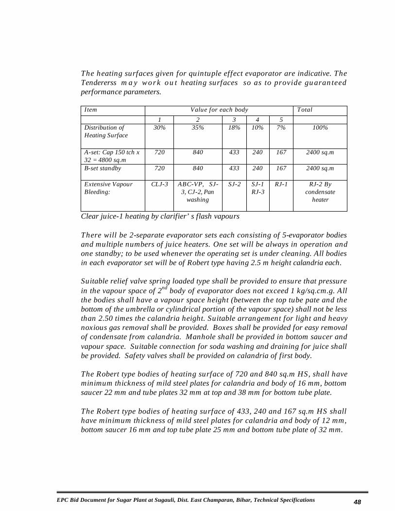
EPC Bid Document for Sugar Plant at Sugauli, Dist. East Champaran, Bihar, Technical Specifications 48
The heating surfaces given for quintuple effect evaporator are indicative. The Tendererss m a y work ou t heating surfaces so as to provide guaranteed performance parameters.
Item Value for each body Total
1 2 3 4 5Distribution of Heating Surface
30% 35% 18% 10% 7% 100%
A-set: Cap 150 tch x 32 = 4800 sq.m
720 840 433 240 167 2400 sq.m
B-set standby 720 840 433 240 167 2400 sq.m
Extensive Vapour Bleeding:
CLJ-3 ABC-VP, SJ-3, CJ-2, Pan
washing
SJ-2 SJ-1RJ-3
RJ-1 RJ-2 By condensate
heater
Clear juice-1 heating by clarifier’s flash vapours
There will be 2-separate evaporator sets each consisting of 5-evaporator bodies and multiple numbers of juice heaters. One set will be always in operation and one standby; to be used whenever the operating set is under cleaning. All bodies in each evaporator set will be of Robert type having 2.5 m height calandria each.
Suitable relief valve spring loaded type shall be provided to ensure that pressure in the vapour space of 2nd body of evaporator does not exceed 1 kg/sq.cm.g. All the bodies shall have a vapour space height (between the top tube pate and the bottom of the umbrella or cylindrical portion of the vapour space) shall not be less than 2.50 times the calandria height. Suitable arrangement for light and heavy noxious gas removal shall be provided. Boxes shall be provided for easy removal of condensate from calandria. Manhole shall be provided in bottom saucer and vapour space. Suitable connection for soda washing and draining for juice shall be provided. Safety valves shall be provided on calandria of first body.
The Robert type bodies of heating surface of 720 and 840 sq.m HS, shall have minimum thickness of mild steel plates for calandria and body of 16 mm, bottom saucer 22 mm and tube plates 32 mm at top and 38 mm for bottom tube plate.
The Robert type bodies of heating surface of 433, 240 and 167 sq.m HS shall have minimum thickness of mild steel plates for calandria and body of 12 mm, bottom saucer 16 mm and top tube plate 25 mm and bottom tube plate of 32 mm.

EPC Bid Document for Sugar Plant at Sugauli, Dist. East Champaran, Bihar, Technical Specifications 49
The bottom saucer shall be welded to the calandria. The domes of the bodies of Robert type evaporators shall have efficient save all of baffle and centrifugal type. A suitable external save-all for fitting in the vapour pipe after the last body going to the condenser shall be provided.
Each body shall have three sight glasses and one light glass; lowest sight glass shall be not higher than 1.50 m from the working platform and 250 mm from top tube plate.
The Robert type bodies shall have, annealed stainless steel tubes confirming to IS: 13316 of 45 mm outside dia and 1.225 mm thick and 2500 mm length shall be used. The pitch of the tube shall be such that the ligament is not less than 10 mm.
Adequate tie rods shall be fixed to avoid movements of tube plates due to thermal shocks for evaporator bodies having 720 and 840 sq.m HS.
The placement of the tubes shall provide effective steam distribution arrangement.
The evaporator sets shall be complete in every respect with fittings for satisfactory operation, 8 mm thick mild steel interconnecting vapour pipes. Syrup extraction system with suitable columns connected to two syrup extraction pumps (one as standby) of 25 cu.m/hr capacity each at 30 m. head through grit catchers of SS: 304 screens shall be provided. Continuous syrup sampler and sampling arrangement from each body shall also be provided. Suitable individual condensate extraction pumps with receiver bottles to be provided to all bodies. The speed of condensate pumps should be not more than 1500 rpm.
Condensate flash heat recovery systems shall be added to minimize steam consumption by 2 - 2.25% cane.
Condensate outlet pipe from various units shall have sight glasses at eye level in addition to sight glasses in extraction columns. The sample cocks shall be provided at all units individually for testing condensate for sugar traces for condensate pumps’ delivery lines, which shall have suitable connection with valve for draining as and when sugar traces are found in the condensate.
Sample cocks shall also be fitted for each evaporator body at inlet of first body, at outlet of last body and in between all evaporator bodies to calculate evaporation rates. There should be sampling cocks provided for un-sulphited and sulphited syrups.

EPC Bid Document for Sugar Plant at Sugauli, Dist. East Champaran, Bihar, Technical Specifications 50
A working platform with staircase from ground level under the bodies for cleaning, repairs and maintenance shall be provided. Platforms with stair cases shall be provided on the top of bodies for operation and maintenance. Walk ways to be provided on top of evaporator bodies for opening valves and man holes.
For open soda boiling, reduced steam entry and vapour outlet to atmosphere at top shall be provided in each body.
Suitable arrangement for preparation of caustic soda solution and pumping the same to the evaporator bodies with recirculation arrangement shall also be provided. Capacity of the tank shall be 200 HL; pump capacity shall be of 20 L/second against a head of 15 meters.
4.4.10 On-Line Conductivity Measurement Of Condensate Water
On line conductivity measurement system shall be provided for measurement of conductivity in condensate return lines from 1st and 2nd body of evaporator set. The system shall have following specifications.
Sensor cum Analyzer:
Based on conductivity principle with tefzel body SS 316 electrode and built in temperature element for automatic temperature compensation. Cell constant for conductivity sensor shall be 0.1 or suitable for low conductivity measurement.
Output: 4-20 mA DC for remote indication and recordingAlarm : High/Low contacts for Alarm annunciators.
4.4.11 Syrup & Molasses Storage Tanks
Total 12 tanks each of 150 HL capacity
Each tank shall be of 150 HL capacity to store syrup, molasses and melt etc at the pan floor. These tanks shall be of rectangular shape. Each tank shall have level indicating device with SS-304 floating ball.
Two or three tanks shall be arranged in one nest depending upon the material to be stored with the provision of separate nest for syrup, each molasses and melt. The tanks shall be made of 8 mm thick mild steel plate duly cross braced with 65 x 65 x 6 mm angle at top, bottom and sides and have 4-numbers tie rods at the top. Molasses storage tank shall be provided with vapour-condensate water heating coils with necessary valves and non-return valves, draining arrangement, pipes, gutters, valve etc.

EPC Bid Document for Sugar Plant at Sugauli, Dist. East Champaran, Bihar, Technical Specifications 51
The wash out connection of each tanks shall be connected by a pipe to juice check weighment tank with proper dilution with water and pumped to juice sulphitation tower with suitable valves. All tanks shall be covered with gratings.
Necessary pipe lines with right angle valves from the tanks to the pans i.e. for syrup, melt, A-light molasses etc. for A-heavy molasses and B- light molasses, B heavy and for C-light molasses shall be provided, for respective A, B, and C massecuite pan.
4.4.12 Molasses Conditioning Units
Three sets: AH=12 MT/hr, BH=6 MT/hr, CL=4 MT/hr
Three Molasses conditioning units complete with inter connecting pipes, valves and sampler shall be provided; one for A-heavy molasses, one for B-heavy and one for C-light molasses. These molasses conditioners will be designed with following capacities in t/hr of molasses:
A-heavy of 12 MT/hrB-heavy of 6 MT/hrC-light of 4 MT/hr
Automatic control of temperature and brix system shall satisfy the following requirements:
i) Temperature of conditioned molasses - 70 oC
ii) Brix of conditioned molasses - 700 - 750
iii) Conditioned molasses shall contain no fine grains
4.4.13 Automatic Brix & Temperature Control Equipment, Molasses Conditioners
The automatic brix and temperature control system for molasses conditioners shall be provided. For each molasses conditioner, the system shall include two control loops consisting of various control system components as specified.

EPC Bid Document for Sugar Plant at Sugauli, Dist. East Champaran, Bihar, Technical Specifications 52
Sr.No.
Control System
Specifications
1. Brix Control System
Brix Control System
2. Sensor Based on conductivity principle with tefzel body SS 316 electrode and built in temperature Element for automatic temperature compensation
3. Transmitter Two wire electronic analogue type with 4-20 mA DC output
4. Controller Microprocessor based single loop indicating type5. Control Suitable for controlling the flow of water in valve
molasses continuously with proportional control6. Temperature
Control System
Temperature Control System
7. Sensor Suitable RTD PT 1008. Transmitter Two wire electronic analogue type with 4-20 mA DC
output9. Controller Microprocessor based single loop indicating type10. Control
ValveSuitable for controlling the flow of steam entering into the molasses condi t ioner Cont inuous ly wi th proportional control
11. Recorder Suitable recorder for recording the controlled brix and temperature of the molasses.
4.4.14 Batch Type Vacuum Pans
All vacuum pans will be of Low Head (LH) Batch type
Equipment Capacity & NumbersAll A, B & C LH batch type pans
40 MT/strike, 5 nos.
Boiling Time: A-2.5= say approximately 3 Hr, B-4 Hr, C-8 Hr
Five LH batch type 40t/str vacuum pans shall be installed.

EPC Bid Document for Sugar Plant at Sugauli, Dist. East Champaran, Bihar, Technical Specifications 53
Each pan shall have double tangential steam/vapour entries. The vacuum pans shall be low head rapid boiling calandria type each having normal strike capacity of 40 tones (280 HL) massecuite. Graining volume in each pan shall preferably not exceed 45 % of strike capacity. Cross section area ratio of all tube ID to down take shall be 140%.
The heating surface of each pan shall be so designed that the ratio of heating surface (m2) to volume (m3) is not less than 6.60. The length of the tube shall not exceed 750 mm.
The tubes shall be of Stainless steel confirming to IS: 13316-92 having 90 mm outside dia. x 1.625 mm thickness. The pitch of the tubes shall be such that ligament is not less than 16 mm. Mild steel tube plates shall be 25-mm thick calandria and body 12 mm, bottom saucer 16 mm. Vapour pipe 8 mm thick. The bottom saucer shall be welded to the calandria in which case suitable arrangement for expansion of tubes in the bottom tube plate shall be provided. Bottom saucer shall be of ring supported design of minimum 750 mm height.
A vapour space of 2.50 m shall be provided in the cylindrical portion above the strike level. The pan shall have internal save-all having centrifugal and baffle type catchall of efficient design. The vapour pipe dia. going to the condenser shall be 900 mm. Each pan shall have feed-check valve after the feed manifold. Pans shall have 7 Nos. sight and 2 Nos. light glasses of 200 mm dia size, light glass with reflector to illuminate the whole tube plate, calibration scale, vacuum gauge and thermometer in vapour space and a compound gauge and thermometer in the calandria.
Each vacuum pan shall be complete in every respect with necessary fittings for satisfactory operation including the pneumatically operated efficient discharge valve of ample capacity, various pipe lines (vapour, syrup, high and low grade molasses, movement water, inter connecting cut over pipe lines etc.) key sampler, vacuum and atmosphere venting. Hot water meter cum recorder capable of measuring 15 m3 /hr of hot water shall be provided. Panometer with automatic feed control system and pneumatically operated discharge valves shall be provided.
The condensate extraction system shall consist of two closed cylindrical receivers installed at the 3.50 meter level on steel staging. The capacity of exhaust condensate receiver shall be 50 HL and that for vapour condensate receiver 125 HL. These tanks shall be complete with level indicator outside the tank and necessary venting arrangement. The condensate piping shall be such that the condensate from low grade pans could go to either of these tanks whereas condensate from high grade pans could go to vapour condensate receiver.

EPC Bid Document for Sugar Plant at Sugauli, Dist. East Champaran, Bihar, Technical Specifications 54
The condensate pipes in these receivers shall lead up to ¼th height from the bottom of the receiver for sealing purpose. Two pumps (one as common stand by) each of 30 m3/hour capacity and one pump of 15 m3/hour capacity against a head of 30 m. shall be provided for pumping the condensate from these tanks to hot water tank.
These pumps shall have minimum 25% leak off to the receivers for maintaining a constant level of the tanks.
Each pan shall have one common vapour inlet valve of 400 mm. Dia. B/C pans shall have common valve for 2 Nos. vapour connection.
Automation of Batch Type Vacuum Pans:
1. Feed control loop: - A feed control loop has to be provided for each vacuum pan. Control loop should consist of conductivity electrodes (self cleaning type) conductivity monitor, micro processor based PID controllers, IP converters and pneumatic control valve. The conductivity monitor shall have to be calibrated for purity range of massecuite during boiling such that ideal brix to be maintained in vacuum pan and is noted vis-à-vis the conductivity monitor to enable set the desired value of conductivity on PID controller.
2. Seed Magma Feed Control: – A system for varying the RPM of the metering pump through the signals received from the pressure transmit the monitoring the vapour pressure in the calandria at pre set value should be available.
3. Absolute Pressure: – A facility to regulate condenser water quantities automatically should consist of one absolute pressure transmit PID controller and an electro pneumatic control valve. The control valve should be fitted on water inlet pipe of the spray nozzles. The water quantity is to be regulated corresponding to the vacuum in the pan.
All control valve sizing should be calculated to ensure an output of each vacuum pan capacity.
General
The complete system consisting of the various above loops, should be provided with a main control panel fitted with all monitors, controllers, indicating lamps, alarm annunciators and hooters.

EPC Bid Document for Sugar Plant at Sugauli, Dist. East Champaran, Bihar, Technical Specifications 55
In addition to the above, the following will also be provided.
1) Molasses quantity flow indicator with integrator
2) Level indicator in the seed magma storage crystallizers.
3) Level indicator in the molasses storage tank with low level annunciation.
4.4.15 Seed & Vacuum Crystallizers
Two Nos. seed crystallizers of 25 MT net working capacity each and three vacuum crystallizers of 25 MT capacity each.
All the crystallizers shall be fitted with stirrer, coupled to 3 kW, TEFC motor with high efficiency planetary reduction gear unit and necessary fittings. The speed of the stirrer shall be about 60 RPH.
These crystallizers shall be installed on pan floor. Necessary interconnecting pipelines between these crystallizers and pans shall be provided.
The shell of the vacuum crystallizers shall be made of minimum 8-mm thick M.S. plate with necessary stiffeners and the end plates minimum 16-mm thick M.S. plate with stiffeners. The seed crystallizer shell shall be 8 mm thick and end plate 16 mm thick with stiffeners.
Vacuum crystallizer shall have four sight glasses on the side and one light glass with reflector at top. One manhole of 500-mm dia. and arrangement for sight glass washing shall be provided. A ladder shall be provided for the approach of seed and vacuum crystallizer. Cut over valves of this crystallizer shall be operable from the pan floor.
Vacuum crystallizers should be near C – Pans and Seed crystallizers towards A –Pans.
4.4.16 Condensers
Two For Evaporators: - Suitable for 600 mm dia vapour pipe.Five For Vacuum Pans: – Suitable for 900 mm dia vapour pipe.
Type of the Condenser – Energy Efficient Type

EPC Bid Document for Sugar Plant at Sugauli, Dist. East Champaran, Bihar, Technical Specifications 56
Each condenser shall be made of 5 mm. thick SS 304 with M.S. hoop rings & tail pipe shall be 3 mm thick of S.S. 304. Suitable platform with railings, access staircase for inspection, repair etc. of the condenser shall be provided. Jet & spray nozzles shall be of SS 304. Condenser shall be so designed that the approach temperature (temp. difference between saturation vapour temp. and tail pipe outlet water temp) should not be more than 5 oC.
Injection water line shall be provided with online strainers. Each strainer shall be outside the condenser at the inlet to enable to clean dirt during operation, through 100 mm dia gate type valve.
Two pressure gauges shall be provided one in inlet and another in outlet of strainer of each condenser.
Special cladding SS-304 material 200 mm dia x 10 mm thick round plates shall be welded in front of each spray nozzle to avoid damages to the body of condenser due to erosion because of force and impingement of water sprays.
Automation of all condensers shall be done to minimize water to vapour ratio to 26:1.
4.4.17 Injection & Spray Water Pumps:
Injection pumps:
Capacity of 1000 m3/Hr – 24 m Head – 3 Nos (1 No. standby)
Spray pumps:
Capacity of 1000 m³/Hr – 15 m Head – 2 Nos (both in operation)
The above pumps shall be of centrifugal type, bronze impeller and fittings and directly coupled to SPDP slip ring induction motor with suitable starter for continuous working. Priming pumps for injection and spray pumps shall be provided. The starting current should not exceed by 300% of full load current.
The injection water pipe connection to condenser should have valve for regulation purpose. A pressure gauge in water line is to be provided. A common header of 600 mm dia and 10 mm thick size shall be provided. Each pump shall have isolating & NRV in delivery line and 2 Nos. drain connection of 100 mm dia with blind shall be provided.

EPC Bid Document for Sugar Plant at Sugauli, Dist. East Champaran, Bihar, Technical Specifications 57
4.4.18 Spray Nozzles & Spray Pond:
No. of nozzles: – 200
7KH�PDLQ�KHDGHU�RI�6SUD\�3RQG�VKDOO�EH�06�FRQVWUXFWLRQ����P�ĭ�DQG�PLQLPXP�10 mm thickness. The branch piping 13 Nos. on one side and 12 Nos. on other side each of 150 mm dia installed at 5.0 meter centre and fitted with 5 Nos. nozzles of 2.20 m. center shall be PVC with support of RCC pillars. Nozzles shall be of thermo engineering plastic with SS insert at throat of nozzle & arranged on the branch piping with single nozzle arrangement. The discharge capacity of each nozzle should be 14.5m³/hr.
The cooling system for the water shall be so designed that at least a drop of 13 oCor within 7 oC of wet bulb temperature, whichever is less should be achieved.
Spray pond and masonry water channels shall be suitably designed.
4.4.19 Cooling, Curing & Grading Plant
Crystallizers
Crystallizers Capacity, MT & NumbersA-AC (air cooled) 45 MT x 4B-WC (water cooled) 45 MT x 1C & R 45 MT x 1C-WC-MVC 150 MT x 1
(i) Four Nos. air cooled each of 45 tones batch type horizontal crystallizers for A massecuite;
(ii) One no. water cooled crystallizers of 45 tones capacity horizontal batch type for B massecuite;
(iii) One no. water cooled crystallizer of 45 tones capacity as receiver for C massecuite;
(iv) One no. 150 tones capacity vertical continuous crystallizer for C massecuite;
The batch crystallizers for ‘A’ massecuite shall be complete with efficient stirring arrangement of sturdy construction. Air cooled crystallizers shall rotate at the stirrer speed of not more than 60 RPH.

EPC Bid Document for Sugar Plant at Sugauli, Dist. East Champaran, Bihar, Technical Specifications 58
Necessary cooling surface to be provided in case of “B” massecuite cooling, so that the massecuite temperature is cooled from 65 oC to 50 oC when supplied with cooling wa ter a t 30 oC. Horizontal type water cooled crystallizer for ‘B’ massecuite shall be rotated at the stirrer speed of not more than 20 RPH.
In case of C massecuite necessary cooling surface shall be provided so that the temperature of the massecuite is cooled from 65 oC to 40 oC in 15 hours, when supplied with cooling water at 30 oC. Provision in the design shall also be made for a maturing period of 4-5 hours in case of low-grade continuous crystallizers. The cooling surface (m2) to volume (m3) ratio shall be minimum 2.0. The heat exchange elements shall be tested at pressure of 6-kg/cm2 g complete with all accessories suitably designed to give a stirrer speed of not more than 20 RPH.
All crystallizers should be driven by shaft mounted high efficiency suitable helical planetary drive system each of 4 kW.
The heat exchange elements of vertical continuous crystallizer should be of Boiler quality or heavy-duty (‘C’ class) MS pipes as per IS-1239 and disc type for horizontal water cooled crystallizer.
The shell of the horizontal crystallizers shall be made of minimum 10 mm thick mild steel plate and end plates 16 mm thick mild steel plate duly reinforced.
For pumping C massecuite from receiver crystallizer to vertical crystallizer and for liquidation of C massecuite from vertical crystallizer: 2 Nos. pumps (1 as stand by) each of 20 t/hr capacity and 30 m head shall be provided.
4.4.20 Centrifugal Machines:
Fully automatic flat bottom plough discharge recycling type machines
Type of massecuite & Machine Capacity, Kg/charge & Nos.A-massecuiteA-machines (22 cycles / hr, 2 working & 1 stand by) 650 x 3
Drive: D.C. thyristor controlled drive shall be provided with 22 cycle /hr. All operations of the automatic recycling type machines including charging and discharging, changing the speed, switching of motor polarity if any, application of superheated wash water, molasses separation, operation, bottom valve closing etc shall be automatic. Manually operated brakes shall also be provided with process logical control programme shall be provided such that the plough should not be operated at higher basket speed than ploughing speed of 60 RPM.

EPC Bid Document for Sugar Plant at Sugauli, Dist. East Champaran, Bihar, Technical Specifications 59
Each machine shall have individual switch fuse isolator of suitable rating, an ammeter, and thyristorised/ air break-contactor for operating the machine in manual and fully automatic recycling with a separate selector switch. All operations such as charging, bringing the machine at different speeds, retardation, water wash, pugmill gate opening and closing, syrup separation, cycle over etc. shall be given on control box and indicated by different lamps. All these applications shall also be possible to be applied by push button/rotary switch in manual or automatic position of the selector switch from the control box except bringing the machines at different speeds, retardation and cycle over.
Necessary arrangement in the panel shall be provided for tripping of the machine in case of high temperature on sensing through ETDs of the motors. The centrifugal machines shall be complete with super heated wash water system working on hot condensate water and AH and AL efficient separation devices.
Continuous Centrifugal Machines:
Type of massecuite & Machine Capacity & Nos.B & C-massecuite 1100 mm x 5Transient heaters 3 Nos.
Five Nos. Continuous centrifugal machines for ‘C’ foreworker dia 1100 mm shall be capable to cure C’ massecuite of minimum 100 brix and 52 purity at a rate of 6MT/hour and shall have a Minimum gravity factor of 2200.
Continuous centrifugal machines for 'B' curing and ‘C’ afterworker dia 1100 mm. capable to cure 12 MT/hour & shall have minimum gravity factor of 2000, ‘C’ massecuite shall be double cured.
The continuous centrifugal machines shall be complete with mild steel monitor casing designed to provide a sturdy support for all machine elements, separate compartment for sugar and molasses, hinged doors for access to the sugar chamber, sugar sampler and water / steam washing arrangement, stainless steelbasket construction, stainless steel inner supporting screen, pure nickel chromium plated working screen, stainless steel accelerating cone, receiving cup, hot water/steam washing arrangement with metering device to measure the wash water, drive arrangement having motor, pulley, V-belts / direct drive and bearings, massecuite feeding device, etc.

EPC Bid Document for Sugar Plant at Sugauli, Dist. East Champaran, Bihar, Technical Specifications 60
The angle of basket shall be 30 deg for ‘B’ & ‘C’ massecuite. Screen for 'C' foreworker machines shall have perforations of 0.06 mm and not less than 7% open area. Screen for B and C afterworker machines shall have perforations of 0.09 mm and 9% open area. The bearing lubrication system shall have built in protecting arrangement to trip the machine incase of failure of lubrication system and or bearing temperature rise.
Operator’s push button panel shall have provision for operating motor, an ammeter and 'ON' indication.
Incoming panels for both batch and continuous type centrifugal shall be designed for a symmetrical fault level of 35 KA (rms) of one second, at unit load factor. All incoming panels shall consist of an ACB, an ammeter, and voltmeter with fuse and selector switch and 'ON' indication. Suitable interlocking arrangement shall also be provided in each self-discharging machine panels such that not more than two machines are started at a time.
Hot monorail crane for all machines:
Monorail with 3 MT capacity chain pulley block over the centrifugal machines shall be provided.
4.4.21 Pug Mills, Magma Mixers & Transient Heaters
Pug mills & magma mixers for high & low grade machines:
Suitable pugmill made out of 6 mm thick mild steel plate and mounted over the machines shall be provided having stirring arrangement, driven by electricmotors, coupled to reduction gear unit. The pugmill feed valve for batch machines shall be operated pneumatically. For low-grade massecuite separate header with transient heater for individual C/F machine shall be provided. Pugmill with drive will be provided for ‘C’ after and ‘B’ machines. All the fore-workers and low grade massecuite afterworker machines to discharge directly into the corresponding magma mixer of suitable capacity and design. The shell of the magma mixers shall be of 6 mm thick mild steel plates having double beater paddles, coupled to electric drive through suitable reduction gear.
Transient heaters:
C-massecuite centrifugal machines shall be fitted with suitable transient heater one for each machine. All transient heaters should have 16 SWG wall thick AISI 304 grade SS tubes.

EPC Bid Document for Sugar Plant at Sugauli, Dist. East Champaran, Bihar, Technical Specifications 61
4.4.22 Air Compressor & Magma Pumps
The centrifugal station shall be complete in all respects and shall have necessary accessories namely Air compressor 7 kg /sq.cm with receiver and refrigerationdryer to supply moisture free air for pneumatic control, mild steel molasses tanks, two of 3 cu.m capacity for A-heavy and A-light molasses and remaining tanks of 2 cu.m capacity each, two molasses pumps of 30 cu.m/hour capacity at 30 meters head for A heavy and light molasses, suitable molasses pumps of suitable capacity of 15 cu.m/hr at 30 meters head for B-heavy, C-light and final molasses with a standby for final molasses.
Magma pumps of suitable capacity at 30 meters head for B foreworker, C-foreworker and C afterworker magma. Magma pumps shall be of rotary type with cast iron rotor having replaceable gun metal or bronze strips and have by-pass arrangements. All magma and molasses pumps shall have vapour-condensate connections with non-return valves and suitable size return pipes with valves from their delivery pipes to the respective tank. The speed of the magma pumps not to exceed 36 rpm, 192 rpm for A & B molasses pumps and 144 rpm for C molasses pumps.
All machines shall be suitably connected to respective molasses tanks for flow of molasses.
4.4.23 Sugar Melter, DSM Screen & Dry Seed Conveyor
Type of massecuite & Machine Capacity & Nos.Sugar Melter 15 MT/hr x 1Automation for sugar melter 1-setDSM Screen, 0.70 mm slit gap 2.134 m width x 1Dry seed conveyor 4 MT/hr x 1
One continuous sugar melter of 15 MT/hour capacity for melting sugar lumps and magma sugars and one melt pump of 20 m3/hour at 30 meters head shall be provided.
A magma mixer and magma pump of 10 MT/hr at 30-meter head shall be provided near the grader for taking dry seed for A massecuite. Necessary water, vapour and other usual connections shall be provided.
One DSM screen of 2.134 m width and 0.70 slit gaps shall be installed for filtration of melt sugar. Washing of screen underneath shall be provided with pressurized hot condensate water from third effect evaporator body.

EPC Bid Document for Sugar Plant at Sugauli, Dist. East Champaran, Bihar, Technical Specifications 62
4.4.24 Automatic Brix & Temperature Control For Sugar Melter
The automatic brix and temperature control system for sugar melter shall be provided. The system shall include two control loops consisting of various control system components as specified below:
Brix Control System:
Sensor Based on conductivity principle with tefzel body SS 316 electrode and built in temp element for automatic temperature compensation
Transmitter Two wire electronic analogue type with 4-20 mA DC outputController Microprocessor based single loop indicating typeControlvalve
Suitable for controlling the flow of water in valve molasses continuously with proportional control
Temperature Control System:
Sensor Suitable RTD PT 100Transmitter Two wire electronic analogue type with 4-20 ma DC outputController Microprocessor based single loop indicating typeControl valve Suitable for controlling the flow of steam entering into
The melter continuously with proportional control
Recorder:
Recorder: Suitable recorder for recording the controlled brix and Temp of the melt.
DRY SEED CONVEYING:
One no of suitable capacity of 4 MT/hr rubber belt conveyor. Rubber Belt conveyor of suitable capacity shall be provided near the grader for taking dry seed for A massecuite.
4.4.25 Grass Hoppers, Sugar Elevator, Sugar Grader & Dust Catcher
Equipment & Machinery Capacity & Nos.Hopper 1.250 m width x 3Elevator & Grader 10 MT/hr x 1, eachSugar dust catcher 5 bags/day (100 kg bag)
EPC Bid Document for Sugar Plant at Sugauli, Dist. East Champaran, Bihar, Technical Specifications 63
Grass Hopper
One single tray grass hopper conveyor of 1.250 M width and 12 m length shall be installed under the " A" machines to convey the sugar discharged from the machines to the first multi-tray grass hopper.
Two multi-tray grasshoppers, each of 1.250 m width and length not less than 12.0 m shall be driven by 6 kW TEFC electric motor with hot air blowing arrangement on the first multi-tray unit and cold air blowing in the second shall be provided. The hopper eccentricity shall be not less than 19 mm and its driving shaft speed shall be 300 to 330 rpm. Portion of the hopper where connecting rod is fixed shall be strengthened by 10 mm plate, 1.00 meter wide. The hopper shall not be welded on longitudinal seams. Each hopper shall have two connecting rods. Sugar lump separating unit shall be provided on second hopper. The drying arrangement at hopper should be in such a way that the bagging temperature of sugar should not be more than 42qC when ambient temperature is note more than 36°C. All drive slats etc. shall be similar and interchangeable.
Suitable radiator type heat exchanger shall be provided to heat air by condensate water.
Sugar Elevator
One No. sugar elevator to deliver 10 MT sugar per hour from the hopper to the grader fitted with suitable components and PVC buckets and driven by a TEFC electric motor coupled to enclosed worm reduction gear unit shall be provided. Approximate height of the elevator shall be suitable for installation 3-bins sugar silo system.
Sugar Grader
The sugar grader shall be of 10 MT/hr capacity having six decks and each deck capable to sieve minimum 4 MT of sugar of any grade and shall be mechanically/electrically vibrator type capable of screening any grade of sugar according to IS specifications. The grader shall be driven by TEFC electric motor. Magnetic iron separator shall be provided for each chute. One sugar distributor for distributing the sugar over full width of grader screen shall be provided. The screens shall be of SS-304 quality material. Arrangement for handling 100 kg and also 50 kg bags shall be provided. Suitable dust catching arrangement shall be provided.

EPC Bid Document for Sugar Plant at Sugauli, Dist. East Champaran, Bihar, Technical Specifications 64
Sugar Dust Catcher
One sugar dust catcher shall be installed of capacity of 5 bags/day. Suitable and efficient sugar dust catching arrangement of wet type shall be provided 5 bags/day, with bank guarantee performance.
4.4.26 Fully Automatic Sugar Silo & Weighing Machines
One set of 3-bins, of capacity 10 MT/hr, for 12 hours storage.
Fully automatic sugar silo and weighing machines shall be provided to handle sugar of 10 MT/hr of various grades.
Three sugar bins shall be of suitable capacities to handle total sugar of 10 MT/hr. The storage capacity of all bins of various sugar grades shall be having capacity to store in bins the sugar production of 16 hours of each grade.
Three Nos. pre-determined balance weight type weighing machines each having capacity to handle 100 kg and also 50 kg HBPE /PP bags of 35 bags/hr.
Suitable electrically operated double row stitch bag stitching machines with one spare head for stitching machines should be as an emergency spare. The bag stitching machines of conveyor type, each suitable for handling about 35 bags of 100 kg each per hour shall be provided. The length of conveyor shall be 4 meters.
Microprocessor based electronic load cells type fully automatic net weighing bagging machines for packing sugar having weighing range of 100 and 50 kg sugar bags, with pneumatic controlled charging and discharging and bag clamps, facility to generate various packing reports viz., hourly, shift wise or daily packing, overweight or underweight bags, having LCD display, facility for printer attachment and transferring data to the computer and operator friendly controller having membrane type key board. Weighing accuracy shall be of r 30 gm.
Suitable bin (MS quality only) storage and automatic bag weighing and filling system with continuous sugar bag stackers shall be adopted.
4.4.27 Molasses Weighing Scale, Final Molasses Tanks & Water Tanks
Equipment Capacity & NumbersMolasses Weighing 1 MT/tip x 1FM-Tank 3000 MT x 2Hot &Cold-W-Tanks –HL x N 150 HL x 3

EPC Bid Document for Sugar Plant at Sugauli, Dist. East Champaran, Bihar, Technical Specifications 65
One automatic molasses weighing scale of 1 MT per tip capacity, complete with registering counter and other accessories, weighed molasses receiving tank of 30 HL capacity and two pump sets (one as standby) each of 10 cu.m/hour for pumping the final molasses to the storage tank at a distance of about 120 m from factory shall be provided. The delivery pipe line shall be raised vertically and the subsequent horizontal portion to have suitable gradient. Provision of check weighment with a suitable tank mounted on platform type scale of 3 MT shall be provided.
Final Molasses Storage Tank
Two Nos. molasses storage tanks of 3000 MT each capacity.
Final molasses storage tanks shall be as per IS: specifications. Two pumps for recirculation of molasses 10 cu.m/hr and 20 m head shall be provided. An overhead tanks of 10 cu.m each capacity shall be installed on staging at a height of 5.00 meters from ground floor with a 300 mm discharge line and valve each to supply molasses to the tanker directly by gravity. Two molasses pumps of 10 cu.m/hr capacity at 30 m head shall be supplied for recirculation and for loading the molasses.
Arrangement for spraying water on all sides of all the molasses storage tanks shall be provided.
Hot & Cold Water Service Tanks
Three overhead tanks each of 150 HL capacity
Four rectangular overhead tanks of 8 mm thick mild steel plates with stiffeners and angle frame each having a capacity of 150 HL complete with valves, fittings, pipes shall be provided. Bottom of the tanks shall be atleast 6.0 meters above Pan floor level. Tanks shall be properly covered. Level indicators for each tank shall be provided.
Two electric driven centrifugal pumps, each having a capacity of 120 cu.m/hour at 30 meters head complete with pipes and valves from the pump to the service tanks shall be provided at suitable place.
Two parallel strainers with isolating valves shall be provided in each of cooling water lines to mill bearings, oil coolers, air compressors, vacuum pumps, etc, so that one will be always stand by for periodical cleaning.
All bearings and oil cooling water shall be collected in a Masonry tank, which should not be more than 15 m away from mill house factory building.

EPC Bid Document for Sugar Plant at Sugauli, Dist. East Champaran, Bihar, Technical Specifications 66
4.4.28 Sugar Go-Downs
Two sugar go-downs of storage capacity of 2 Lakh bags each. Sugar go-downs shall be as per IS standards, having automatic humidity control devices.
4.4.29 Water Conservation & Circulation
It is necessary that the general service water intake shall be minimized near to the zero levels to achieve water conservation. This also should apply to water discharge. All excess water condensates from the sugar plant shall be cooled, filtered, treated and recycled for the entire sugar plant. Excess cooled condensate water shall be lead to the injection water make up purposes after chemical treatment to achieve desired neutral pH values.
Floor washing, juice heaters, evaporator bodies and vacuum pan washing and brushing shall be done only with the help of these excess condensates.
Water Conservation Recirculation System
Necessary arrangement shall be provided for recirculation of cooling water from mill bearings, enclosed mill drive gear boxes, crystallizers, air compressors and sulphur burners etc. All equipments like M.S. fabricated collection tank of suitable capacity, 3-nos pumping sets (one as standby) piping, valves etc shall be installed at suitable location. This water shall be pumped to raw water reservoir through spray nozzles installed on the reservoir itself to achieve the atmospheric cooling.
All of excess condensate water shall be cooled down and re-used for bearing and coolers loop and make of spray water. Thus, there should be zero water discharge to ETP.
4.4.30 Miscellaneous
Pressure Reducing & De-Superheating Systems (PRDS), Header & Valves
Capacity of 20 TPH. The PRDS System shall be provided with automatic steam reducing valve to maintain a steady pressure of 1.75 kg/sq.cm.g pressure at 1250-1300c in the receiver at the inlet of header at evaporator station for requirement of exhaust steam for the sugar plant.
The capacity of steam required shall be 20 MT/hr minimum and 25 MT/hr maximum.

EPC Bid Document for Sugar Plant at Sugauli, Dist. East Champaran, Bihar, Technical Specifications 67
Suitable automatic de-superheating arrangement and relating system to be provided to maintain a steady temperature of 130 oC plus-minus 5 oC, in the exhaust steam receiver by automatic de-superheating of the entire exhaust steam The de-superheated steam coming out of the exhaust steam receiver shall be saturated and dry.
There shall be provision for adjusting the pressure in exhaust steam receiver at any pre-set valve in the range of 1.50 to 2.00 kg/sq.cm.g.
Two water pumps with electric drive of suitable capacity (one standby) for injecting water in the specified reduced pressure steam lines through pneumatically operated control valves shall be provided for de-superheating the exhaust steam.
The reducing valve shall be provided with pneumatically operated pressure controllers designed to maintain steady pressure with down steam flow rate variation from 10% to 100% of the rated capacity with overriding control system. One electric driven air compressor with receiver and piping shall be provided for operation of the reducing valves and de-super heaters.
One steam flow meter shall be provided in the high pressure side of the reducing valve system at the inlet of the exhaust steam header.
One steam pressure recorder capable of recording pressure from 1.50 to 1.75 kg/sq.cm.g shall be provided in the exhaust steam line near the Evaporator station.
A dial thermometer of 150 mm dia and 0-200 oC range shall also be provided in the exhaust line. One temperature recorder to record the temperature up to 200 oC shall be provided in the exhaust line near the Evaporator station.
Suitable bypass arrangements for each automatic reducing valve to be provided for manual operation. Isolating valves shall be provided to isolate the automatic valve for repairs while working. Steam strainers at upstream side of each reducing valve shall also be provided.
Provision only for start up & standby purposes:
The second branch shall be provided with one automatic steam reducing valve to maintain a steady pressure of 7-8 kg/cm2 g. in the receiver from the prime mover of power plant by injecting steam up to 2 t/hr after reducing pressure from boiler steam pressure to 7-8 kg/cm2 g.

EPC Bid Document for Sugar Plant at Sugauli, Dist. East Champaran, Bihar, Technical Specifications 68
Suitable automatic de-superheating arrangement and relating system to be provided to maintain a steady temperature of 170 oC. Plus-minus 5 oC in the steam receiver by automatic de-superheating of the entire make-up steam. The steam coming out of the steam receiver shall be dry.
Two pressure pumps with electric drive of suitable capacity (one standby) for injecting water in the two reduced pressure steam l ines through pneumatically operated control valves shall be provided for de-superheating.
All the reducing valves shall be provided with pneumatically operated pressure controllers designed to maintain steady pressure with down steam flow rate variation from 10% to 100% of the rated capacity with over riding control system. One electric driven air compressor with receiver and piping shall be provided for operation of the reducing valves and de- super heaters.
One steam flow meter shall be provided in the high pressure side of the reducing valve system.
One steam pressure recorder capable of recording pressure up to 2.50 kg/cm2 g. shall be provided in the exhaust steam line near the Evaporator station. A dial thermometer of 150 mm dia and 0-300 oC range shall also be provided in the exhaust line. One temperature recorder to record the temperature up to 300 oC shall be provided in the exhaust line near the Evaporator station.
Suitable bypass arrangements as per IBR for each automatic reducing valve to beprovided for manual operation. Isolating valves shall be provided to isolate the automatic valve for repairs while working. Steam strainers at upstream side of each reducing valve shall also be provided.
Bagasse Baling Machines (to be located at suitable space in bagasse yard)
Two bagasse bailing presses of hydraulic type, to handle 2.50 MT / hr each of bagasse having 50% moisture and complete with 20 kW slip ring induction motor etc shall be provided.

EPC Bid Document for Sugar Plant at Sugauli, Dist. East Champaran, Bihar, Technical Specifications 69
4.4.31 Supporting Structure & Material Specifications
(Staging and structure for 3500 TCD juice extraction diffusion process and 1750 to 1925 TCD crushing capacity at sugar process house).
Factory pan floor levels shall be of gravity flow type. Necessary staging for all the machinery including supporting columns, integral floor structure, staircases, railings etc shall be provided. Mills, mill drive, diffuser, clarifier and lime slaker shall be on RCC staging. Sulphur furnaces shall be on steel staging with RCC flooring. Other machinery except those on floor level shall have its own supporting steel staging.
Pipelines, cable trays, mill house cranes, condensers, flash tanks, cyclone separators can be supported on building columns. No weight of other machinery or platform shall be transmitted to building columns.
Mills and diffuser shall have mild steel grating flooring. Centrifugals shall have chequerred plate flooring. In the boiling house chequerred plate flooring shall be provided.
All gangways, passages, staircases, working platforms and railings shall be of convenient chequerred plate thickness of minimum 5 mm.
Staging and structure provision shall be made in the space and area, for additional juice heaters, clarifier, evaporator set, syrup and molasses storage and supply tanks, vacuum pans, crystallizers, centrifugal machines, hoppers, grader and sugar silo systems for designed crushing rates. A clear working platform of atleast 2.50 m width shall be provided in working front of pans and evaporator b o d i e s . Moving space between pans shall be 1000 mm and in between evaporator bodies a distance of 1000 mm minimum shall be provided. In case of other units a clear working platform of atleast 1.50 m width shall be provided.
All statutory requirement regarding staging platform staircases, safety devices etc shall be observed at the design stage.
General Material Specifications have been indicated below:
x Gun metal used for bushes and bearings shall conform to IS: 318-1965. x Phosphor bronze castings shall conform to IS: 28-1975.x The mill drive pinions shall be made of cast steel as per IS: 2708-1973 B
Grade III and gear wheels as per IS: 2708-1973 Grade II. x Cast iron flexible couplings shall conform to IS: 2693-1964.

EPC Bid Document for Sugar Plant at Sugauli, Dist. East Champaran, Bihar, Technical Specifications 70
x Glass wool for vessels and piping shall conform to IS: 3690-1974 type 2. Mineral wool shall conform to IS: 5696-1970. The thickness shall be to suit the temperature and diameter of pipes.
x Sheet rubber shall conform to type 8 of IS: 638-1965 Grades to suit the nature of work.
x Compressed asbestos fibre shall conform to IS: 2712-1971.x Cast iron sluice valves shall conform to IS: 780-1969.x Gun metal valves shall be of heavy duty and shall conform to IS: 778-
1971.x Plummer blocks used for roller bearings shall conform to IS: 4773-1968.x The slide rails for electric motors, if of grey cast iron conform to grade 15
of IS: 210-1962. The slide rails shall be as per IS: 2968-1964.x Stirrer shaft for crystallizers, pug mills, magma mixers, lime tanks,
sugar melter, juice sulphiter, molasses dilution tank etc. shall conform to 30 C8 of IS: 1570-1979, except when mild steel fabricated pipes are used.
x Mild steel plates shall conform to IS: 2062-1969 in case of fabricated base plates, gear beds, for mill drive and all fabricated parts subjected to steam pressure higher than 1.5 kg/sq.cm.g.
x Structural steel and mild steel plates conforming to IS: 226-1975 shall be used for the fabrication of rest of the machinery and equipment.
Stability Certification Of Staging & Structure
It is necessary to check, verify and get certified the strength and designs of proposed staging and structure used for equipment and machinery for both the proposed crushing rates.
4.5 Other General Design Criteria
In designing factory building and engineering layout criterion should be attached to local wind direction mainly during crushing season to ensure the following. General layout of plant and machinery shall show equipment for 3500 TCD at juice extraction diffusion process and 1750 to 1925 TCD crushing capacity at sugar process house.
The specifications of plant and machinery, wherever not mentioned in these specifications for 3500 TCD, shall be according to the guide line specifications designed and finalized by the technical committee of Government of India in November 2003 and 1987 and should incorporate the following:

EPC Bid Document for Sugar Plant at Sugauli, Dist. East Champaran, Bihar, Technical Specifications 71
1) In designing factory building and engineering layout criterion should be attached to local wind direction to ensure the following. General layout of plant and machinery shall show equipment for 3500 tcd.
1) Effective natural ventilation of Mill, Diffusion and Sugar Boiling Houses.2) Non contamination of circulating waters by acidic agents.3) Statutory requirements of pollution preventions.
2) The factory floor levels as well as injection channels and cooling spray pond levels shall be decided to suit the topography at the Sugar Plant site. All floors shall be well designed and given sufficient slopes to keep factory clean and neat. All gutters shall be well sealed and kept under ground levels. All pumps shall be provided with SS pots grouted under ground near pumps to collect all leaked sugar liquids and fill up again in the same source.
3) Plant and machinery to confirm to all State and Central Govt laws.
4) All the cranes in the Sugar Plant (including cane unloader) should have box type bridge girders (and not lattice type). All the gear boxes installed on the cranes should be helical high efficiency type having hardened and ground teeth.
5) The 4-sets of manufacturing design drawings, 4-sets O & M manuals, 4- sets of drawings, 4-sets of detailed specifications etc should be supplied by the Seller to the Purchaser 4 months before the scheduled date of commissioning of the Sugar Plant and should also include the following:
i) List of Ball/Roller bearings fitted in the Sugar Plant (equipment wise stating bearing Nos.)
ii) List of all electric motors installed in the Sugar Plant (equipment wise stating motor type, H.P., RPM etc.).
iii) List of all Reduction gear boxes installed in the Sugar Plant (equipment wise stating gear box type, ratio, H.P., rating, service factor etc.)
iv) List of pumps installed in the Sugar Plant (pump type, duty, discharge, total head etc.)
v) List of all coupling bushes, oil seals, vee belts etc fitted in the Sugar Plant (stating size wise quantity and equipment name where the part is fitted).

EPC Bid Document for Sugar Plant at Sugauli, Dist. East Champaran, Bihar, Technical Specifications 72
6) The venders shall not make the use of building columns and trusses for lifting weights of machinery during erection. Factory building structure should not be used as staging for any items of machinery and equipment (except mill house cranes & piping).
7) All the Grit catchers in the Sugar Boiling Process Plant should be 800 mm dia x 1000 mm height – shell 8 mm thick, bottom 10 mm thick, cover plates 20 mm thick. Covers should be hinged and cover holding bolts should be 25 mm dia. The bucket screens should be made of 3 mm thick, AISI 304 quality S.S. and should have sturdy handles for lifting.
8) Condensate outlet pipes from various units to have sight glasses at eye level in addition to sight glasses in extracting columns. Test cocks should also be provided for taking out all condensate samples.
9) Test cocks should be provided in condensate outlets of all units individually for testing water for sugar traces. All the condensate pumps delivery lines should have 50 mm NB connection with a valve to let out the water in the drain, as and when sugar traces are found in the condensate.
10) Size of Condensate Receivers for Juice heaters and Evaporators should be 400 mm dia x 1200 mm height – Shell 8 mm thick, bottom 10 mm thick.
11) The speed of the motors of the condensate extraction pumps should be not more than 1440 RPM.
12) Heating surfaces of juice heaters, direct contact juice heaters, evaporator bodies, pans and all other heat exchangers shall be calculated on the basis of mean dia and effective tube length with contact of heating fluid.
13) All the pumps of juice, lime and syrup should be provided with suitable grit and sand catchers in the suction side. Also, juice delivery lines should be provided with non-return valves.
14) All the centrifugal pumps should have stop and non-return valves in the delivery pipes.
15) Centrifugal pumps: The service water pumps, injection and spray water pumps, syrup pumps, melt pumps should be bronze fitted wherever not mentioned, otherwise these and other (except at mill house and diffuser) centrifugal pumps should conform to IS-5659 and IS-5120 specifications.
EPC Bid Document for Sugar Plant at Sugauli, Dist. East Champaran, Bihar, Technical Specifications 73
16) All the vapour line of the pans and last bodies of the evaporator set should be provided with manhole to enable accessibility inside the vapour lines for cleaning and chemical resistance painting purposes. One 100 m dia x 150 mm long nipple should be welded in the vapour pipe along with a blind flange to enable water filling of the vapour line.
17) The diameter of the pipes for filling water into bodies and calandrias of evaporator and pans should be not less than 100 mm size.
18) All the gate valves for massecuite and magma lines should be of rising spindle type only.
19) The sluice/right angle valves used in exhaust steam and vapour pipelines should have stainless steel internals and S.S. spindles.
20) Suitable capacity float ball type steam traps should be provided in the exhaust line for the outlet of the condensate for quality condensate recovery.
21) Steam flow meters of indicating, integrating and recording type shall be provided for exhaust steam and for PRDS.
22) Temperature recorders for raw, sulphited juice, evaporator exhaust steam, injection outlet/inlet water and vacuum recorder for last body of evaporator shall be provided at appropriate place.
23) For lagging the equipments, pipes and fittings, juice heaters, evaporator bodies, vacuum pans, headers, valve bodies, flanges, drain pipes etc of the sugar plant as per specifications the Sellers scope of supply should be as follows:
All the equipments and pipelines (including fittings as defined under Clause 6 of IS: 7413 specifications), surfaces in the sugar plant above 55 oC. temperature should be effectively lagged (except where heat dissipation is desirable and the surfaces which become hot intermittently such as steam traps and relief valve outlet pipes, vents, pipes etc.)
EPC Bid Document for Sugar Plant at Sugauli, Dist. East Champaran, Bihar, Technical Specifications 74
Specifications of Lagging Material to be used:
i) For lagging: Factory made mattresses of Bonded Glass wool/Rock wool/Mineral wool as per IS: 8183 – (latest issue) specifications. The bulk density of the material should be:
a) 50 kg/m3 for hot surface temperatures up to 250 oC.(As per clause 3.2 of IS: 8183 – (latest issue) specifications)The thickness of the lagging should be such that the difference between temperature measured (at any t ime during the maintenance warranty period as per clause of the draft agreement) at any point on the outer surface of the lagging cladding (i.e. protective finish) and the ambient temperature at that time should not exceed 10 oC.
ii) For protective finish:
Material for cladding of all lagging in the sugar plant should be cotton canvas (as per IS: 7413 standard specifications) (except as follows).
a) The valves and flanges (including the flanges of the equipment) to be lagged and shall be provided with openable lagging boxes for valves and fittings of the LP exhaust steam lines, openable boxes shall be out of 18 SWG thick aluminum sheets as per IS: 737 designation 31000 condition H3.
b) All the lagging should be provided with boxes of 3.20 mm thick Aluminum sheets. Lifting blocks should be provided for these boxes.
c) Balance materials (not specified above) should be as per IS: 7413 specifications.
Application and finishing of the lagging materials, protective coverings etc should be carried out by the Seller as per IS: 7413 (latest issue) specifications.
24) All maintenance tools, special tools, tube expanders etc shall be supplied by the Seller to the Purchaser as per scope of supply stipulated under this Agreement should be brand new and should not be those used by the Seller for erection and commissioning of the Sugar Plant.
25) All nuts and bolts and non-return valves should be as per ISI specifications.26) In cases tensile strength or solidity has been mentioned the supplier shall submit a
suitable certificate of the same from original manufacturer/Govt. approved testing laboratories/Govt. Engineering Colleges.

EPC Bid Document for Sugar Plant at Sugauli, Dist. East Champaran, Bihar, Technical Specifications 75
27) Suitable arrangements shall be provided for continuous sampling of followinga) Primary juiceb) Diffuser juicesc) Last mill juiced) Mixed juicee) Clear juicef) Un-sulphited syrupg) Sulphited syrup
4.6 Interface Piping
All hot and cold water, juice, syrup, magma, molasses, massecuite and bled vapors, reduced pressure and exhaust steam pipe lines and headers shall be suitable for processing mixed juice of 3500 TCD at juice extraction diffusion process and 1750 to 1925 TCD crushing capacity at sugar process house.
Various pipelines shall be designed so that velocities given below are not exceeded:
Material Velocities m/sWater and juice Suction 1.0 m/second, Delivery 1.20 m/secondCondensate Suction 1.0 m/second, Delivery 1.20 m/secondSyrup Suction 0.5 m/second, Delivery 1.00 m/second.Molasses Suction 0.3 m/second, Delivery 0.50 m/second.Massecuite-Magma Suction 0.1 m/second, Delivery 0.15 m/secondSuperheated & Saturated steam
30.00 m/second
Exhaust steam 30.00 m/secondBled vapours 30.00 m/second.Compressed air- SO2 20.00 m/second
All common headers, pipelines, valves etc shall be designed for 3500 TCD juice extraction diffusion process and 1750 to 1925 TCD crushing capacity at sugar process house.
Safety valves shall be provided in the exhaust steam pipe lines wherever necessary. Blow off pipes shall extend beyond the roof to be taken out from the sides of walls and partitions. There should not be a single venting line vertically in the top roof of the factory buildings. All vents shall be provided in the side walls or partitions.
Safety valves in the exhaust and reduced pressure lines shall be dead weight type and additional hand lever operated.

EPC Bid Document for Sugar Plant at Sugauli, Dist. East Champaran, Bihar, Technical Specifications 76
Suitable drains, valves, steam traps etc shall be provided in all steam lines, where ever necessary. All the steam traps shall be of ball float type.
The condensates coming out from the entire ball float type traps from exhaust steam and vapour lines under pressure shall be collected in suitable tanks and as such no condensate should be allowed to drain in the gutters of the sugar plant. The quality condensates shall be sent directly to the steam boiler of cogen plant.
The pipes shall conform to specifications given below:
(i) Cast Iron Pipes and Fittings:
The pipes shall be class 'B' and shall conform to IS: 1537-1976 specifications and integrally cast flanged joints or spun pipes with screwed ends on flanges as per IS: 1536-1976 shall be used.
The pipe fittings shall be class 'B' and shall conform to IS: 1538 (part I to XXIII) -1976 specifications. Only flanged joints shall be used. One side of the flanges shall be machined in case all pipe fittings.
(ii) Mild Steel Pipes
All mild steel pipes and pipe fittings used for conveying of air, cold water, to water (except boiler feed water) oil (except oil for hydraulic accumulators), molasses, massecuite, juice, lime, syrup, noxious gases etc. shall conform to IS: 1239(part I)-1976 and IS: 1239 (part II)-1982 specifications. All juice and syrup piping including imbibition juice piping shall be class `C' (heavy) and rest of the piping shall be class `B' (medium). The thickness of mild steel pipes having diameter more than 200 mm shall be 8 mm.
In case of all piping above 25 mm NB only flanged joints shall be used. All flanges to be as per IS: 6392-1971.
(iii) Exhaust steam piping:
These shall conform to IBR wherever applicable. The thickness of exhaust and vapor steam piping shall be minimum 8 mm in case of 300 mm dia. and above.
The distance between two flanges in straight portion of pipes shall not exceed 6 meters except steam, vapor pipe. In case of bends, flanges shall be provided atleast at one end. All steam expansion bellows shall be of stainless steel tested at 1.5 times the exhaust steam pressure.

EPC Bid Document for Sugar Plant at Sugauli, Dist. East Champaran, Bihar, Technical Specifications 77
Valves shall be provided in each branch line of juice heater,, reduced pressure steam lines, water separator, drain, steam trap etc.
All delivery lines of juice, water and syrup of centrifugal pumps shall have non-return valves except in case of unstrained re-maceration juice pump, lime and Mud pumps. Water connections shall be provided at each station for cleaning.
All exhaust steam valves for evaporator and pans shall be of right angle type valves with suitable leak proof seats.
(iv) Bearing cooling piping:
All bearing and oil cooling water shall be collected in a masonry tank which shall not be more than 15 meters away from the factory building.
EPC Bid Document for Sugar Plant at Sugauli, Dist. East Champaran, Bihar, Technical Specifications 78
Chapter – 5
Energy Efficiency Improvement
5.1 Steam Consumption
The Tendererss to evaluate and provide following specific proven steam economy measures for achieving guaranteed performance parameters for steam consumption of 22% on cane. Additional possible measures for the purpose or even for lower steam consumption than to be guaranteed may be separately quoted.
i) Installing full automation system fo r t h e entire sugar plant, and particularly for sugar process house to reduce steam and power consumptions.
ii) Avoiding medium pressure steam of 5-7 bar entirely, during normal operation of the sugar plant.
iii) Making use of dynamic, vapour line and direct contact juice heaters. iv) Using waste exothermic heat of SO2 gas for melting sulphur powder. v) Heating of clear juice CJ-1 by using flash heat from clarifiervi) Utilization of condensate flash heat energy at evaporator station.vii) Arranging Quintuple set and evaporator bodies for extensive vapour
bleeding and minimizing condenser vapour load near to zero.viii) Heating of sulphited juice in two stages.ix) Using noxious gases back to immediate low pressure vapor lines to
recover the waste heat.x) Use of third body vapors for special melter for B-seed.xi) Pan body washing with second effect vapours.xii) Intensifying pan circulation by using less height calandrias of 750 mm.xiii) Controlling movement water in vacuum pans by using flow meters.xiv) Using all second body vapours at pans and minimizing the use of first
body vapors.xv) Super heating wash water at centrifugal machines by exhaust condensatesxvi) Using vapor condensate heat for heating air at sugar hoppers.xvii) Sugar melting by syrup, pan condensate water and non condensable gases
under vacuum.xviii) Using non-condensable gas’s heat for molasses conditioners, syrup and
filtrate heating.xix) Using waste heat of blow down water using heat exchangers at boiler

EPC Bid Document for Sugar Plant at Sugauli, Dist. East Champaran, Bihar, Technical Specifications 79
5.2 Power Consumption
The Tendererss to evaluate and provide following specific proven power economy measures for achieving guaranteed performance parameters for power consumption of 23 KW / MT at 150 TCH. Additional possible measures for the purpose or even for lower steam consumption than to be guaranteed may be separately quoted.
i) Providing star connection instead of delta for motors with constant low loads up to 35%, such as final molasses pump, C-light molasses pump, sugar melter, sugar elevators, weighed molasses transfer pump, B-continuous grain pumps, sugar melter screw pump, belt conveyor and all crystallizers.
ii) Providing adequate size motors for various applications and providing star delta controllers for drive motors expected to operate at less than 50% capacities and where fluctuating loads are envisaged for applications like magma pumps, dry seed pumps and mixtures, molasses conditioners and milk of lime stirrers.
iii) Providing energy efficient electrical motors having efficiencies more than 90%.
iv) Providing bigger sized equipment and machinery to minimize number of machinery, such as at A, B and C massecuite centrifugal machines.
v) Providing variable speed drives (VFD) for variable speed and different flow applications like cane carrier drive and other motors at variable flow rate pumps such as raw juice, sulphited juice, imbibition, injection, condensate and service water pumps, rake cane carriers and inter carriers, magma pumps and super heated wash water pumps.
vi) Providing voltage controllers in the circuit of general lighting applicationsfor reduction of voltage to 210 V instead of 230-240 Volts, without affecting luminous intensity.
vii) Providing high efficiency planetary gear drives at crystallizers, magma mixers, vacuum and seed crystallizers and pug mills.
viii) Providing high efficiency helical gear units at all carriers, cane yard equipment, magma and massecuite and molasses pumps, milk of lime equipments, molasses conditioners etc.
ix) Elimination of power drives by using gravitational force at cush-cush conveyors under DSM and for filter cake conveying by using gravity discharge chutes.
x) Providing capacitor banks of adequate sizes at MCCs, to reduce cable losses.xi) Providing level controller switches for juice and sugar dust collector tanksxii) Providing automation of massecuite feeding to continuous centrifugal
machines and Sugar plant automation by DCS / MPBA (micro processor based control automation) at ACFC, Auto power factor controls, condensers, vacuum pans etc and interlocking of machinery and equipment.

EPC Bid Document for Sugar Plant at Sugauli, Dist. East Champaran, Bihar, Technical Specifications 80
xiii) Providing of high voltage (11 kV) AC motors for heavy duty higher power machinery like fibrizer, where constant speed is desired.
xiv) Providing anti friction roller bearings instead of bush-journal bearings at mill gearing, cane carriers, rake inter carriers, crystallizers, pug mills, magma mixers etc.

EPC Bid Document for Sugar Plant at Sugauli, Dist. East Champaran, Bihar, Technical Specifications 81
Chapter – 6
Electrical Distribution System
6.1 General Design Basis
6.1.1 Design Criteria in Equipments / Power Distribution
a. All Busbars shall be Air insulated and of ALUMINIUM. Busbar size shall be selected based on Temperature limit of 85 ºC at Busbar for the rated current.
b. Power Cables (HV & LV) shall be XLPE armoured ALUMINIUM conductors above and including 6 sq. mm. size. Power cables including and less than 4 sq. mm. shall be copper conductor.
c. Squirrel Cage Motors up to 15 KW shall have automatic DOL Starter suitable for operating from MCC, DCS and PB Station near Motors.
d. Motor rating above 15 KW up to 200KW shall be with Automatic Star Delta Starter suitable for operating from MCC, DCS and PB Station near Motors.
e. Motor rating above 200KW shall be operated with Soft Starter suitable for operating from starter, DCS and PB Station near Motors. Starter shall have bypass contactor with AC3 rating.
f. VFD shall be provided as per the functional requirement.
g. Following spare feeders shall be considered in Power Distribution
- In 11 KV Switchboard - 1 No. Transformer feeder
- In Cogen Aux. L. T. Panel - As per SLD
- Panels in other areas including PCC / MCC / DB - 1 No. of Each Rating
h. MCC shall be floor mounted self supporting, dust and vermin proof, fixed type construction.
i. Power Control Center (PCC) shall have Switch Disconnector Fuse up to 630A and above 800A these shall have Manually operated Draw Out (MDO) type ACB.’ON’ indication shall be provided on outgoing feeders.

EPC Bid Document for Sugar Plant at Sugauli, Dist. East Champaran, Bihar, Technical Specifications 82
j. Motor Control Center (MCC) shall have Switch Disconnector Fuse unit, Contactor and Bimetallic Over Load (O/L) relay for starters. Starters on MCCs shall have ‘ON’ & ‘TRIP’ indication. The selection of switchgear components shall be minimum with one stage higher than Type II co ordination as per IS 13947
k. Motor protection shall be provided in ACVF Drives & Soft Starters, as inbuilt protection functions.
l. Rating of Switchboard incomer ACB/SDF shall be 1.2 times the operating load current. Protection & Indication (For HV Switch board)
m. Flameproof equipments such as Push Button Stations, junction boxes, Lighting Switches, L lighting Fixtures etc shall be considered with hazardous area classification in Ethanol plant.
n. Push Button Station with Shrouded type actuator for ON push button, Lockable Mushroom type actuator for OFF Push button with Aluminum die cast enclosure shall be provided. Push Button Station for Motors above 15KW rating shall be provided with suppressed scale Ammeter. Push Button Station for VFD shall have SpeedSetting Potentiometer and speed indicator in addition to Push Buttons and Ammeter
6.1.2 Power & Distribution Transformer
The following criteria shall be applicable for the sizing of Transformer
a) Total Connected Load shall be calculated based on Motor List.b) Operating Load shall be calculated excluding Standby Loads and
equipment for maintenance such as Crane.c) Load Factors shall be considered on Operating Loads according to
Load Factor to consider shall be as below:- Motor Loads with DOL / S/D Starter / Soft Starters :
0.85- Motor Loads with VFDs 0.75- Lighting Loads : 1.0- Utility Plug Sockets : 0.5- Cranes, winches etc. : 0.1
d) Average Power Factor 0.8 shall be considered to arrive at KVA.e) Equipment Efficiency shall be considered 90% as average.f) On such Calculated load + 20% Margin shall be considered.g) If necessary percentage impedance shall be increased more than the
impedance indicated in IS to limit 415 V side Fault Level to 50KA for 1 sec.

EPC Bid Document for Sugar Plant at Sugauli, Dist. East Champaran, Bihar, Technical Specifications 83
6.1.3 Power Factor Improvement
a) Plant PF shall be required to improve above 0.95b) This is achieved by providing:
Capacitors across HV Motors as per recommendation of manufacturer. Provide Automatic Power Correction Panel with required no. of APP type capacitor banks in 415V PCC in Cogen Plant, Sugar Plant and Distillery plant. In Sugar Plant fixed type capacitors can be connected additionally near MCC with appropriate capacitor duty contactor and FSU feeder in MCC.
c) To determine number of capacitors following consideration be givenOperating KW & Average operating P.F.Drive with VFD shall maintain P.F. above 0.95. These loads shall not to be considered for deciding capacitor rating.
6.1.4 LV Power Control Centre (PCC)
The following points shall be considered while designing and selection of components.
a) TYPE OF FEEDERS:Incomers : D.O. – 3-Pole ACB Emergency PowerSupply Feeder
: D.O. – 4-Pole ACB
Outgoing Feeders : SDF up to 630 A: MDO Type ACB Above 800A
b) BUSBARS Color Coded Sleeved Aluminum Bus bar Size shall be selected as per following norms:Continuous current carrying capacity as per the Rated Current of IncomerTemperature Rise LimitShort Circuit Withstand Capacity
6.1.5 Motor Control Centre (MCC) :
The following points shall be considered while designing & selecting components.
a) Incomer Feeder
- MDO ACB above 800 A up to 2000 AFixed Switch Fuse Disconnector up to 630 A

EPC Bid Document for Sugar Plant at Sugauli, Dist. East Champaran, Bihar, Technical Specifications 84
b) Outgoing Starter Feeder
Feeders shall be comprising of:Switch Fuse Disconnector ContactorsThermal Overload RelayTimer in case of Star Delta StartersPush ButtonsIndicating Lamps
c) Bus bar Above 125A rating
d) Control Logic
- Plant shall be capable of operation from MCC, DCS located at Central Control Room or locally from Push Button Station near motor.
- It will be possible to start the Motor locally through enable command from PLC.
- P.F. and KW parameter of Incomer shal l be communicated to PLC.
- ON/ OFF Status of the Motor shall be communicated to PLC.
e) Provision o f S p a r e feeders
In MCC total 10% spare feeders shall be provided, depending on feeder ratings in MCC following feeders shall be provided.
6.1.6 LV Bus Ducting
Bus duct up to 3200A shall be CRCA enclosure with color coded sleeved Aluminum bus bar. Short circuit rating shall be 50KA, 1 sec.
6.1.7 Battery & Battery Charger
a) BATTERY: - VRLA Maintenance Free - Capacity shall be determined by total operating load
& 20% margin- AH shall be determined for 8 hour backup time
b) BATTARY :CHARGER
Float and Float cum Boost with 20% capacity
c) DCDB : Built in with Battery charger panel with Incomer as MCCB & Outgoing as MCB

EPC Bid Document for Sugar Plant at Sugauli, Dist. East Champaran, Bihar, Technical Specifications 85
6.1.8 Grounding / Earthing System & Lightening Protection
a) Earthing shall be done according to IS 3043 – 1987.b) Earthing shall be carried out by G.I. Strips & Wires. Earth Electrodes
shall be G.I. Plate type & Pipe type as per requirement. However, Transformer Neutral will be connected to G.I.Earth Electrode through Copper Strip.
c) Total Resistance of Earthing system shall be Less than one ohm.d) Plant shall be protected against lightning according to IS 2309-1989.
6.1.9 Cables
The following consideration shall be given for Cable Sizing and Selection on Nominal Current Capacity
a) Ambient Temperature in Air/Groundb) Continuous Load Currentc) Short Circuit Withstand Capacityd) Voltage Drop at the Starting of Motor limited to 15% & 5% at Steady
state up to motor terminals.e) Deration Factor due to type of Laying & Grouping.f) Generally Power and Control cables shall be stranded.g) XLPE insulated cables upto & including 4 sq.mm shall be with stranded
copper conductors. Cables of 6 sq.mm & above size shall be with Al. conductor
6.1.10 Cable Trays, Accessories & Support
a) Generally Cable trays shall be prefabricated Hot Dip Galvanized Ironb) Cable Trays shall be run in Vertical formation as far as possible.c) HV & LV Power Cables shall have separating distance of 300mmd) Separating distance between Power and Control cable shall be
300mm.e) Instrument cables & screened shall run on perforated cable tray having
300 mm separating distance of 300 mm.
6.1.11 Illumination System
a) The Lux Level in various indoor areas shall be as per IS. In plant areas, the lighting shall be provided as per functional requirement.

EPC Bid Document for Sugar Plant at Sugauli, Dist. East Champaran, Bihar, Technical Specifications 86
b) HPMV Well Glass with integral control gear box fittings (IP55) shall be provided in plant areas. Industrial FL. Lamp fittings will be provided in sub station and other indoor areas. Mirror Optic fixtures shall be provided in CCR. In outdoor areas HPSV Lamp fixtures (IP 55) shall be provided.
c) The lighting shall be catered by Main Lighting DB. LDB & SLDB connected by Al. conductor cables. The Emergency power supply from 415V DG set will be made available to lighting transformer in case of failure of power
6.1.12 HV & LV Motors
Motors shall be as per IS 325. LV motors shall be IP 55 degree of protection and for HV motors the degree of protection shall be IP 55 (CACA). Motors shall have insulation of class F and temperature rise limit of class B. Motors shall be designed with 50 ºC ambient. Flame proof Enclosure shall beprovided for motors where ever required.
6.2 Scope of Work
In line with the overall battery limits for the sugar plant and particularly for the electrical power, the Tenderers will have to consider following in the scope of work for electrical distribution system:
x 11 KV Cables (2 sets.) from cogen power plant 11 KV distribution board, up to sugar plant 11 KV panel.
x 1 1 K V panel comprising of VCB, CTs / PTs, meters, protective relays, required cables and terminations, etc.
x 11 KV cables from 11 KV panel in the sugar plant, up to 11 KV motors like fibrizor and cutter
x 11 KV / 433 V distribution transformers of adequate size along with all necessary incoming and out going cables / bus bars, protection system, safety devices, fire fighting system, etc.
x Lightening protection for buildings in sugar plant area as per IS 2309.

EPC Bid Document for Sugar Plant at Sugauli, Dist. East Champaran, Bihar, Technical Specifications 87
x 415 V distribution network within the sugar plant including main distribution panel, incoming / out going cables / bus bars, CTs / PTs, protection relays,annunciator, indicating lamps, push buttons, DCDB, battery & charger, safety devices, distribution boards, incoming / outgoing cables, indicating lamps, push buttons, etc. for all drives.
x High mast lighting fixture with 30 m high tower including cradle, motor operated mechanism, 8 nos. – 400 W, metal halide lamps – total 4 nos. to be installed at designated places as advised by Owner with all electrical connections.
x 11 KV / 690 V converter transformer of adequate size along with all necessary incoming and out going cables, bus bars, protections, panels, ACBs, safety devices, fire fighting system, etc. for driving DC motor
x 415V supply feeder suitable for 100 KW for providing power to colony and other miscellaneous areas within the entire integrated complex.
6.3 Diesel Generating Set For Emergency Electrical Power Supply
One No: 250 kW and one no. of 50 kW rating diesel sets each with 0.80 power factor shall be installed for the sugar plant.
The diesel generating set shall be continuously rated comprising multiple cylinder diesel engine having necessary protections such as low lube oil pressure trip, high engine temperature trip, over speed trip etc. and shall be fitted with speed control knob speedometer, hour meter battery charging meter, oil pressure and temperature gauges, radiator etc.
The diesel engine shall be coupled with suitable alternator capable of developing continuously the rated power at 3 phase, 4 wire, 50 Hz at normal voltage of 440 V AC. Alternator to be suitable for voltage range of 440 V AC and conforming to IS-4722 specifications. The alternator shall be fitted with minimum one ETD in each phase for thermo protection of the alternator windings. The alternator shall be designed for an ambient temperature of 45 oC. The alternator shall be self excited and self regulated.
The diesel set shall be complete with base frame, couplings, one M.S. fabricated, diesel service tank of 15 HL capacity, inter-connecting piping, D.C. storage battery and self starting mechanism for starting of engine.

EPC Bid Document for Sugar Plant at Sugauli, Dist. East Champaran, Bihar, Technical Specifications 88
One 2 mm thick for the back side and 1.6 mm thick for the other sides cold rolled sheet steel fabricated floor mounted, dust and vermin proof panel for the diesel set shall be provided. The panel shall be fitted with air circuit breaker, over current relay, earth fault relay, reverse power relay, over voltage relay, reed type frequency meter, neutral isolating switch, three phase 4 wire unbalanced energy meters, kW meter, 3 phase power factor meter, 3 nos. ampere meters, one no voltmeter with selector switch, ON-OFF indicting lamps.
The panel shall have neutral and phase bus bars of electric grade (EC-91E) aluminum and shall be designed to withstand symmetrical short circuit current of 35 KA (RMS) for one second. The panel shall be designed for an ambient temperature of 45 oC the operating temperature of the bus bars shall not exceed 85 oC. All the meters shall be class 1.50 per cent accuracy and shall conform to IS-1248 specifications. All the meters shall be square type of 100 mm sq. with 90 per cent deflection Inter connecting electrical cable 3½ cores from the diesel set to the main distribution panel and to the auxiliary panel changeover switch shall be provided.

EPC Bid Document for Sugar Plant at Sugauli, Dist. East Champaran, Bihar, Technical Specifications 89
Chapter – 7
Control & Instrumentation System
7.1 Introduction
It is essential to have full automation of the sugar plant along with required instrumentation and systems at various equipment / locations, as well as a centralized DCS system. The details of automation, of ACFC, imbibition water, diffuser, mass flow meters, pH control system, on line conductivity measurement of condensates, brix & temperature control of juice sulphiter and molasses conditioners, all batch vacuum pans, sugar melter and sugar silo system, etc. have already been specified in the previous chapters under each equipment and machinery.
The Tendererss may provide the control & instrumentation system according to these specifications and / or provide additional systems for achieving guaranteed performance parameters for the sugar plant operation, as well as for reducing the manpower requirement. Additional systems may be quoted separately.
7.2 Statutory Requirements
7.2.1 Online Mass Flow meters:
1) Depending upon the plant conditions like size, flow rate, specific gravity, viscosity the vendor shall furnish detailed sizing calculations showing mass flow rate accuracy, pressure drop, velocities at 10 operating steps.
2) Weights and measures certification and stamping from regional Weights and Measures authority shall be provided.
3) Manufacturer shall have facility for weight calibration of mass flow meter in the flow laboratory as per NIST standards.
7.2.2 Automatic pH Control for Juice/Syrup Sulphitation:
Well designed and fabricated sampling system for cooling the juice at 40oC for effective online pH measurement.
7.2.3 Online Brix Indicators
1) Brix measurement shall be independent of changes in the other process parameters like pressure, temperature additives etc.

EPC Bid Document for Sugar Plant at Sugauli, Dist. East Champaran, Bihar, Technical Specifications 90
2) Instrument shall be fully configured, operated and maintained using operators' interface. It shall have large backlit digital display, soft push buttons and easy to operate menu driven screen.
7.2.4 Online Conductivity Measurement of condensate water
1) To ensure the compatibility the sensor and transmitter shall be of same make.
2) Well designed and fabricated sampling system for each line shall be provided.
7.2.5 Instrumentation Panel
The entire panel mounted instruments which are integral part of the following control and measurement systems shall be housed in a well designed, fabricated and wired instrumentation panel.
1) Auto Cane Feed Control System2) Automatic Imbibition Water Flow and Temperature Control System3) Online Mass Flow Meter for mixed juice and water [existing]4) Automatic pH Control System for Juice Sulphitation5) Online Brix Indicators6) Automatic pH Control System for Syrup Sulphitation7) Automatic Brix and Temperature Control of Molasses Conditioner & melter8) Online conductivity measurement of condensate water9) Automatic massecuite level control in pug mill10) Massecuite feed control for continuous centrifugal machine.
7.2.6 DCS-Based Automation
For recording various process parameters like pressure, temperature, flow level etc at various equipments in the boiling house two numbers µ-p based 32 channels data loggers’ specifications with inkjet printer having following specifications shall be provided: one at evaporator floor and the other at pan floor.
Specifications
For recording various process parameters like pressure, temperature, flow level etc. at various equipments in the boiling house two numbers µp based 32 channels data loggers’ specifications with 80 column dot matrix printer/132 column dot matrix printer/inkjet printer having following specifications shall be provided: one at evaporator floor and the other at pan floor.
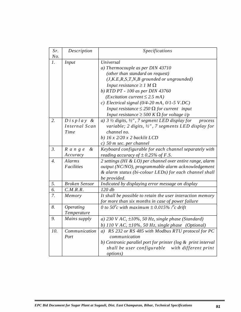
EPC Bid Document for Sugar Plant at Sugauli, Dist. East Champaran, Bihar, Technical Specifications 91
Sr. No.
Description Specifications
1. Input Universala) Thermocouple as per DIN 43710
(other than standard on request) (J,K.E,R,S,T,N,B grounded or ungrounded) Input resistance t 1 M :
b) RTD PT - 100 as per DIN 43760(Excitation current d 2.5 mA)
c) Electrical signal (0/4-20 mA, 0/1-5 V.DC)Input resistance d 250 : for current inputInput resistance t 500 K : for voltage i/p
2. D i s p l a y & Internal Scan Time
a) 3 ½ digits, ½", 7 segment LED display for process variable; 2 digits, ½", 7 segments LED display for channel no.
b) 16 x 2/20 x 2 backlit LCDc) 50 m sec. per channel
3. R a n g e & Accuracy
Keyboard configurable for each channel separately with reading accuracy of r 0.25% of F.S.
4. Alarms Facilities
2 settings (HI & LO) per channel over entire range, alarm output (NC/NO), programmable alarm acknowledgement & alarm status (bi-colour LEDs) for each channel shall be provided.
5. Broken Sensor Indicated by displaying error message on display6. C.M.R.R. 120 db7. Memory It shall be possible to retain the user interaction memory
for more than six months in case of power failure8. Operating
Temperature0 to 50oc with maximum r 0.015% /oc drift
9. Mains supply a) 230 V AC, r10%, 50 Hz, single phase (Standard)b) 110 V AC, r10%, 50 Hz, single phase (Optional)
10. Communication Port
a) RS 232 or RS 485 with Modbus RTU protocol for PC communication
b) Centronic parallel port for printer (log & print interval shall be user configurable with different print options)

EPC Bid Document for Sugar Plant at Sugauli, Dist. East Champaran, Bihar, Technical Specifications 92
7.2.7 Drawings, Design Details & Documentation
The following documents shall be sent to the Owner and copy to the Consultant for approval.
1) Instrumentation hookup diagram.2) P & I diagram.3) Specification of instruments i.e. Range, make etc.4) Orifice plate design calculation data sheet as per BS 1042 for flow meters.5) Control valve sizing and CV calculations.6) Instrument control panel cutout, foundation and panel wiring drawing.7) List and specification of erection material.
* Impulse tubing shall be of SS 316/304 15 NB SCH 40 pipe with SS isolating and drain valves.
* Instrument cables from field transmitters to panel shall be 1.5 mm x 2 core Cu conductor armoured cable.
The following documents shall be submitted in triplicate along with instruments to the end user:
1) Erection drawing and instrumentation calibration and test reports.2) Operation and servicing manuals.
7.2.8 Central Data Acquisition System
It shall be possible to connect all the data loggers to the centralized PC based data acquisition system
7.2.9 Instrumentation Control Rooms
To achieve the desired working performance of various instrumentation measurements and control system even under extreme conditions like shock, vibrations, humidity, electrical interference installation of instrumentation panel shall be done in well designed and constructed rooms as per the standard instrumentation practices. Rooms shall be constructed by the vender as per his requirements. Air Conditioners shall be installed by vender as per his requirements to satisfy performance of equipment, machinery and instruments.
Full automation of entire sugar plant shall be done to achieve 15 workers per shift in phase-I and 20 total workers per shift in phase-II.

EPC Bid Document for Sugar Plant at Sugauli, Dist. East Champaran, Bihar, Technical Specifications 93
7.3 DCS Based Automation
Sr. No.
CONTROL BASE
STATION WISE AUTOMATION
1 MPBA Cane carrier automation, ACFC2 MPBA Digi ta l & Mechanical dewatering Mill-roller lift
indication3 MPBA Dewatering mill and inter carriers’ speed control by
mounting bagasse level sensors in Donnelly chutes4 MPBA/ABA Imbibition water control automation by monitoring last
dewatering mill juice brix and load5 MPBA Juice flow stabilization6 MPBA Juice tip jumbo display digital type unit7 MPBA Electronic static type juice weighing scales and
molasses weighing scale8 MPBA Automatic juice pH control system9 MPBA Automation of evaporator station to control level of
liquid in individual bodies and brix of syrup10 MPBA Pressure reducing and de-superheating station11 MPBA Automation of molasses conditioners12 MPBA Automation of sugar melter13 MPBA Automation of super heating of wash water system14 MPBA Automation of centrifugal machines 15 MPBA Automation of Batch & Continuous vacuum pans 16 MPBA Automation of condensers, cooling and condensing
systems
EPC Bid Document for Sugar Plant at Sugauli, Dist. East Champaran, Bihar, Technical Specifications 94
Chapter – 8
Civil Works
8.1 The existing buildings and structure at the site location need to be dismantled / demolished completely, to make the available plot clear for construction of sugar plant, as well as associated cogen power plant and ethanol plant. The appointed EPC contractor will have to take up this responsibility entirely and the relevant cost and time schedule to be indicated in the EPC bid. Appendix - I gives the list of identified existing buildings and structure to be demolished by the select EPC contractor.
8.2 Design philosophy and criteria for civil and structural construction at the project site has been indicated in the ensuing paragraphs.
8.2.1 Major Civil Works
1. Dismantling/ demolishing of all existing buildings & structures within the entire area & removal of debris from the entire site area about 65-70 acres.
2. Contour survey, soil testing, tests for ascertaining the soil bearing capacity, water tables at site, wind direction etc.
3. Back filling and levelling, if required4. Chain link/barbed wire fencing, gates, entrance arches etc., for sugar
plant and other non-plant buildings etc.5. Cane / marshalling yard and nursery6. Foundations for 3500 TCD sugar plant and machinery7. Foundations for cooling systems for sugar plant8. Foundations for bagasse handling equipments9. Main Factory building and auxiliary structures for sugar plant
10. Sugar Go-downs/Warehouses/Machine Shop/Store building/ lime, sulphur and gunny bags go-downs, Excise offices, Workers rest rooms, panel rooms, worker’s rest room, first aidfacility, fire fighting facilities including sheds for fire tenders, foundations for fire fighting equipments, pipe lines for fire fighting/fire hydrants etc. and other auxiliary buildings
11. Non plant buildings such as canteen, laboratories, toilet blocks, effluent disposal schemes, etc.
12. Water supply scheme including gravity/rising mains, jackwell, percolation galleries, pipelines, pumping machinery etc.
13. Water reservoir of minimum 7 days capacity14. Foundations for large tanks, pumps, fuel conveyors, pipe racks, electrical
equipment, pipe / cable racks, water treatment equipment and all other equipments

EPC Bid Document for Sugar Plant at Sugauli, Dist. East Champaran, Bihar, Technical Specifications 95
15. Panel rooms, sheds for equipments, sheds for DG sets16. All internal roads to be of RCC and RCC approach roads within the
sugar plant area to be provided for all building / structures including green areas, road side drains, culverts, pipelines and other provisions for street lighting, yard lighting, area lighting etc.
17. Drainage channels, storm water drains within sugar plant area 18. Underground cable & bus ducts, trench for CW piping, etc.19. Earthing pits and earthing mats20. Required plumbing and sanitary fittings & equipments.21. Rain water harvesting, ETP, sewage treatment plant and green belt22. Pile foundation to be provided, if required, based on soil investigation23. Landscaping for the sugar plant area 24. All building and civil work commencement certificates, building
completion certificates, stability certificates, any other certificates as per statutory requirements of the Bihar and the Central Government, NOC of the BPCB, NOC of Airport Authority etc., all necessary permissions from the statutory authorities.
25. All electrification and lighting26. Fire fighting
8.2.2 Design data:
The following basic design criteria are used in the designs of various structures.
Soil bearing capacity (to be verified : 12 ton/m² at 2 m from NGLby Tenderers, prior to civil design)Min grade of concrete for RCC works : M20Grade of reinforcement steel : IS : 1786Type of Cement : 43 grade Portland cementAll structural steel members : As per IS 800Seismic zone of factory area : As per IS 1893-2002Wind velocity & direction : Velocity : As per IS : 875
South-West (May- Sep), North – East (Oct – Apr)

EPC Bid Document for Sugar Plant at Sugauli, Dist. East Champaran, Bihar, Technical Specifications 96
8.2.3 System Description and Specifications
a) Site Grading and Levelling
The site clearance and grading work has been considered only of the area for the plant. The grading work will be done by cutting-filling balance method and no earth will be transported from outside. All excavation and back filling shall be in Contractor’s scope. The contour survey and all necessary surveys of the total area for the integrated plant shall be carried out by the EPC Contractor.
b) Plant Internal Roads And Culverts
Internal roads within the plant boundary and roads for access to equipment and buildings will have to be provided. Layout of the roads will be based on Plot Plan. Adequate turning space for vehicles will have to be provided and bend radii will be set according to maximum vehicle speed of 20km/hour. Roads to be as short and straight as possible. All internal roads shall be well designed RCC roads. All roads shall be designed as per IEC 58. Wherever drains or other underground facilities cross the roads, concrete pipe culverts class NP2 or NP 3 as required or RCC box culverts shall be provided. Roads shall be provided with kerb stones and the same shall be painted as per specification.
All plant roads will be constructed so as to permit transportation of all heavy equipment. Internal roads will be minimum 6.0m wide.
c) Soil Investigation
Soil investigation will be done by EPC Contractor for the determination of safe bearing capacities for the design of foundations for various structural elements. Earth resistivity will be determined. If required and necessary, pile foundation design shall be adopted for the major and critical foundations.
8.2.4 Design Criteria
The design criteria for various structures and structural elements will be as follows:
a) Steel Framed Structures
The design of steel framed structures will be done by linear elastic method as per the provision of IS: 800.

EPC Bid Document for Sugar Plant at Sugauli, Dist. East Champaran, Bihar, Technical Specifications 97
b) Reinforced Concrete Framed Structures
All reinforced concrete structures will be moment resisting frames along both longitudinal & transverse directions. The suspended slab will be considered as continuous over secondary beam and will not form part of the framing system. However it will be considered to be transferring the shear to the framing system. RCC structures/members will be designed as per IS:-456 using limit state method.
8.2.5 Foundations
Introduction
All main plant structures i.e. Sugar Plant Buildings, including Silos, Transformer Foundations, buildings and foundations, all plant and non-plant buildings for the integrated plant and other Misc. Buildings will be supported on RCC foundation -isolated, combined or raft and/or pile foundations. Machine foundations for Compressors, BFP and misc. pumps and equipment foundations will be supported on RCC foundations - Isolated or Block foundations and/or pile foundations. Pile foundations will be provided, if required, by the soil investigation report.
Design
The foundations will be designed for the most critical combination of forces and moments, resulting from all the possible combinations of the various loading from the structural system. The effect of water table will be considered and the foundation will be checked for overturning for minimum and maximum vertical loads. There should be no uplift under any portion of the foundation for any loading condition. The foundation sections will be sized and reinforced adequately for bending moments and shear stresses. A levelling course of plain cement concrete will be provided before casting the foundation.
8.2.6 Machine Foundations
Introduction
This section outlines the design philosophy & construction aspect for foundations for large equipment as follows:
a) Diffuser foundation, fibrizor foundationb) All major and minor foundations for the sugar plantc) Compressor foundationsd) All Miscellaneous machine foundations

EPC Bid Document for Sugar Plant at Sugauli, Dist. East Champaran, Bihar, Technical Specifications 98
General
A necessary requirement for all rotating machinery is that it should be properly supported. Thus the foundation becomes an important element of machine installation. It has to resist both static and dynamic forces exerted by the machine and transmit these to the ground. In doing so, it is responsible for smooth running of the machine by ensuring that amplitudes are limited to values that are permissible for the machine and for local environment, including structures and people. The foundation must have sufficient structural strength to withstand all applicable forces and most severe combination of individual load cases that result in the maximum foundation loading for any conceivable set of normal or abnormal circumstances. Spring supported foundation shall be provided for low frequency machines, wherever the same are required from technical consideration.
Design Parameters
The data required for the analysis and design of machine foundations may be listed as under:
a) Loading diagram showing static and dynamic loads on the foundations, points of application of loads, area over which these loads will be distributed etc.
b) Operating speed of the machine.c) Capacity or rated output of machine.d) Critical speeds of the machine.e) Geometric limitation.f) Opening limitations, depressions, projections etc.g) Details including sizes and locations of anchor bolts, pipe sleeves, inserts,
embedded parts etc.h) Layout and distribution of pipe lines, ducts etc. and their supporting details.i) Temperatures in various areas during operation.j) Mass moment of inertia.k) Allowable amplitudes at the machine bearing points, etc.l) Tolerance in bearing and clearances of various components.
Loads
The loads to be considered for analysis and design are:
a. Static loads of the stationary components of the entire assembly along with the static weight of rotating parts.
b. Dynamic loads from start-up torque.

EPC Bid Document for Sugar Plant at Sugauli, Dist. East Champaran, Bihar, Technical Specifications 99
c. Loads on foundation resulting from admissible forces and moments of pump nozzles.
d. Loads on pedestal top due to installation and maintenance.e. Any other forces/loads which equipment EPC Contractor considers
applicable.
Analysis And Design
The analysis and design of machine foundations will be carried out to ensure the following:
a) Compliance with the manufacturer’s requirements.b) No resonance phenomenon of a disturbing nature to machine operation should
exist at the normal running speed.c) Calculations to be performed for dynamic as well as static cases for reinforced
concrete block type pedestal.
Foundation Sizing
The outline plan dimensions of foundations will be given by the machine EPC Contractor. The height of foundation will be selected after taking into consideration soil strata and operating level of the machine. The eccentricity of common CG of machine and foundation with respect to the centroid of base area/pile group should not exceed 3% of the corresponding base dimensions of the foundation.
In order to reduce the horizontal amplitudes, the height of foundation should be selected as small as possible. A larger base dimension should be selected in the direction of rocking moment, if any, acting on the foundation.
Compressor Foundation
The Compressor is a machine of reciprocating type. This is a low speed machine and produces unbalance forces during operation, causing vibration in the foundation. Excessive foundation vibrations may cause settlement or damage to the foundation-machine system and also a feeling of discomfort and uneasiness to the personnel. Compressor foundation shall be isolated from the close slab and other foundations
Vibrations are also transmitted through the ground. Ground vibrations may be minimized by providing trenches all around the foundation up to a suitable depth.

EPC Bid Document for Sugar Plant at Sugauli, Dist. East Champaran, Bihar, Technical Specifications 100
Miscellaneous Machine Foundations
For the large variety of other types of machines there are numerous foundation designs and the most suitable one will depend on the particular application.
Foundations for pumps, etc. are usually in the form of solid block foundations, resting on the undisturbed strata.
At machine supports supported on the finished floors, floor may be thickened and extra reinforcements provided. Also, the machines, which are almost vibration free and are very light to moderately heavy, may be supported in the above manner. Rubber or neoprene pads may have to be used under some of these machines to reduce transmission of vibrations to the supporting floor.
8.2.7 General Design Considerations
The design of various civil and structural works will be done as per relevant Indian Standard and sound engineering practices to meet the system and functional requirements.
Design Loads: Design loads for all structures will be determined according to thecriteria described below.
Dead Loads: - Dead loads will consist of the weights of the structure and all equipment of a permanent or semi-permanent nature including tanks, wall panels, partitions, roofing, piping, drains, electrical trays, bus-ducts. Dead loads will be determined using the weight from IS-875 (Part -1).
Live Loads:- Live loads will consist of uniform live loads and equipment live loads. Uniform live loads are assumed unit loads which are sufficient to provide for movable and transitory loads, such as the weight of people, portable equipment and tools, equipment, or parts which may be moved over or placed on floors during maintenance operations. These uniform live loads will not be considered on floor areas which will be permanently covered with equipment.
Equipment live loads are calculated loads based upon the actual weight and size of the equipment and parts to be placed on floors during dismantling and maintenance or to be temporarily placed on or moved over floors during installation. Floors and supporting members which are subject to heavy equipment live loads will be designed on the basis of the weight of the equipment in addition to a uniform load of 500 kg/m², or specifically defined live loads, whichever is greater. Each member in the floor which may carry these loads will be designed for the heaviest piece or pieces of equipment arranged in the most critical position.

EPC Bid Document for Sugar Plant at Sugauli, Dist. East Champaran, Bihar, Technical Specifications 101
For loads caused by moving equipment over the floor for installation, consideration will be given to the shoring of beams and floor from floors below. When moving equipment over floors for installations are considered, stress increases of 25 percent are permitted in beams and columns.
Wind Speed: The design wind speed will be based on IS: 875 (Part - 3). This design wind speed will be used to determine wind loads for all structures.Seismic Zone: As per IS: 1893-2002
Design Loads
Dead Loads
Dead load will comprise of the following and will be computed as per IS: 875 (Part-1). Following will be considered for evaluation of dead loads:
i) An uniform 150/200 mm thick RCC slab wherever concrete floors are provided
ii) An uniform floor finish of 50 mm laid over RCC slabiii) Other area flooring will consist of removable grating/chequered plate
or 50 IPS.iv) Beams & columns as per actual sizev) Wall/cladding loadsvi) Self weight of supporting structure/facilities
Imposed Loads
Imposed loads will include minor equipment loads, cable trays, small pipe racks /hangers (not exceeding 250 Kg/m²) and also loads during erection, operation & maintenance.
Actual plant loads coming on the floor area occupied by the equipment will be calculated and compared with the superimposed loads given above. Higher of the two will be adopted for analysis and design.
Steam Piping Load
As per static/dynamic analysis for steam piping, the loads superimposed on structure by piping hangers and at the restraint points will be considered as advised by piping Contractor. However, pipe dynamic forces at hanger location/restraint points will be considered not to act simultaneously with seismic forces in that plane.
EPC Bid Document for Sugar Plant at Sugauli, Dist. East Champaran, Bihar, Technical Specifications 102
Crane Loads
The frames will be analyzed for the maximum wheel loads when the lifted weight is nearest to ‘A’ row in one case and ‘B’ row in another load case. The impact factor for vertical load will be 25% for crane girder and 10% for columns /foundations as per provision of IS: 875 and lateral crane surge of 10% of lifted weight and trolley weight will be considered in the analysis of the frame. The longitudinal surge will be 5% of the static wheel load. Each of the crane girders will be analyzed for the moving loads and for half the total surge loads on each gantry girder.
Wind Loads
The basic wind pressure will be taken as IS: 875(Part-III) and combination of wind loads with other types of loading will be done according to provision of IS:875 (Part-V). The basic wind speed of 50m/sec. up to height of 10metres above ground level.
Earthquake Load
As per IS: 1893, the seismic zone and basic horizontal seismic coefficient for thisplant location will be decided. The importance factor of not less than 1.50 will be used to calculate base shear coefficient. The coefficient of soil-foundation interaction will be not less than 1.0. Reduction in live loads is to be considered for analysis according to IS: 875. In view of the asymmetrical nature of main powerhouse, response spectrum method will be used for analysis.
Temperature Loads
The effect of temperature loads will be considered for design of the structural frames. For temperature loading calculation the total temperature variation will be considered as 2/3rd of the average annual variation in temperature. The structure will be designed to withstand stresses due to 50% of the total temperature variation. The structures will also be analyzed/checked for temperature effects in the areas where the temperature rise is expected to be high.
Load Combinations
The following load combinations will be considered for finding out the critical forces, moments and torsion on the structural elements.

EPC Bid Document for Sugar Plant at Sugauli, Dist. East Champaran, Bihar, Technical Specifications 103
i) DL + LLii) DL + LL + CLA + DLC ± CSiii) DL + LL + CLB + DLC ± CSiv) DL + LL + CLA + DLC ± CS ± TLv) DL + LL + CLB + DLC ± CS ± TLvi) DL + 0.5LL + K1(DLC) + K2(CLA)vii) DL + 0.5LL + K1(DLC) + K2(CLB) + EL ± TLvii) DL +LL + DLC + K3(CLA) ± K3(CS)+ WL1+TLviii) DL +LL + DLC + K3(CLB) ± K3 (CS)+WL1+TLix) DL +LL + DLC + K3 (CLA) ± K3 (CS) ± WL2+TLx) DL +LL + DLC + K3(CLB) ± K3(CS) ± WL2 ± TLxi) DL +LL ± WL1 ± TLxii) DL + LL ± WL2 ± TL
The following load combinations will be used for getting max. tension at column base which will be used for the design of holding down bolts
i) 0.9DL ± ELii) 0.9DL ± WL1iii) 0.9DL ± WL2
Nomenclature
DL Dead load (comprising of only dead weight of structural members, side cladding etc.)
LL Live load (including imposed load, plant loads & equipment loads)TL Temperature loadDLC Dead load of crane bridge with impactCLA Crane trolley + lifted weight nearest to A row column with impactCLB Crane trolley + lifted weight nearest to B row column with impact.CS Crane surgeEL Earthquake loadWL1 Wind load with internal suction of 0.2pWL2 Wind load with internal pressure of 0.2pK1 (DLC)Dead load of crane bridge without impactK2 (CLA)Crane trolley without lifted weight with impact or (CLB)K3(CLA) Crane trolley + ½ lifted weight with impact or (CLB)K3(CS) Crane surge for ½ lifted weight.
EPC Bid Document for Sugar Plant at Sugauli, Dist. East Champaran, Bihar, Technical Specifications 104
Permissible Stresses
The permissible stresses will be as per relevant IS Code. An increase of 33.3% in permissible stresses will be made wherever wind or earthquake load has been considered with dead load and appropriate amount of live load. For secondary effects without wind or earthquake load, permissible stress will be increased by not more than 25%.
8.2.8 Design Of Miscellaneous Items
a) Cable Trenches
The cable trenches and pre-cast removable RCC cover (with lifting arrangement) will be constructed using RCC/Masonry work. The cable trench walls will be designed for the following loads:
1. Dead load of 155 Kg/m length of cable support and 75 Kg on one tier at the end.
2. Triangular earth pressure + uniform surcharge pressure of 2T/m².3. Cable trench covers will be designed for self-weight of top slab and
concentrated load of 200 Kg at center of span on each panel.4. Cable trench crossing the road/rails will be designed for class AA
loading of IRC/relevant IS code and should be checked for transformer loading.
Suitable drainage arrangement will be provided to drain water from cable trenches. Cable trenches will not be used as storm water drains. The top of trenches will be kept at least 50mm above the finished ground level. Trench wall will not foul with the foundation. Suitable clear gap will be provided.
A clear (vertical) space of at least 200-mm will be available for each tier in cable trench. From trench bed to lowest tier, a minimum clearance of 150 mm will be available. The trench bed will have a slope of 1/500 along the run and 1/250 perpendicular to the run. All the construction joints of cable trenches i.e. between base slab to base slab, the junction of vertical wall to base slab, from vertical wall to wall and all the expansion joints will be provided with approved quality PVC water stops of approx. 230 x 5 mm size for those sections where the ground water table is expected to rise above the junction of base slab and vertical wall of cable trenches.
Cable trenches will be blocked at the ends if required with brick masonry in cement sand mortar 1:6 plaster with 12mm thick 1:5 cement sand mortar.

EPC Bid Document for Sugar Plant at Sugauli, Dist. East Champaran, Bihar, Technical Specifications 105
b) Drains
Adequate surface drainage system will be provided within the plant area. Design will be done with obtained rainfall data and the storm water drainage system designed, (Culverts, ditches, drains etc.) to accommodate the most intense rainfall that is likely to occur over the catchments area in one hour period on an average of once per ten year. The surface of the site will be sloped to prevent the ponding of water.
The maximum velocity for pipe drains and open drains will be limited to 2.4m/ sec and 1.8m/ sec respectively. However, minimum non-silting velocity of 0.6 m/sec will be ensured. Longitudinal bed slope will not be milder than 1 in 1000.
Invert of the drainage system will be decided in such a way that the water can easily be discharged above the High Flood Level (HFL) outside substation boundary at suitable location and approved by Owner. Pumps for drainage of water (if required) will be provided.
8.2.9 Architectural Concepts And Design
An Architectural Design Basis Report will be submitted to the Owner including proposals for the following scheme components: shape, form, color, and basic materials for interior and exterior architecture along with an appropriate landscaping scheme. All schemes will be supported by architectural statement explaining the factors considered in the design.
EXTERIOR ARCHITECTURE : General design criteria for the exterior architectural systems will be as follows:
a) Wall / Cladding System
All external walls of the building shall be 230 mm thick brick walls and internal walls 230/115 mm thick brick walls as per requirement in CM 1:5. Internal plastering shall be 12 mm thick using CM 1:4 and external wall with CM 1:4., 20/25 mm thick and/or sand faced plaster or any other special finish if required, 115 wall shall be plastered with CM 1:3, 12 mm thick. Ceiling plastering shall be 6 mm thick with CM 1:3. Damp proof course 40 mm thick in PCC 1:2:4 using 6 mm down stone shall be provided in the external brick walls at grade level.

EPC Bid Document for Sugar Plant at Sugauli, Dist. East Champaran, Bihar, Technical Specifications 106
In order to quickly erect / complete the Sugar Plant buildings, wall cladding with Galvalume sheets may be examined above 5.0 m from ground level and up to 5.0 m brick work can be adopted. Where ever advised, self supported galvalume roofing could also be provided for the main plant buildings and other non-plant buildings.
b) Roof
As per details given in relevant sections.
c) Flooring & Floor Finish
The floor slabs will be designed as cast-in-situ RCC slabs with removable shuttering unless mentioned otherwise. The nominal thickness of RCC slabs will be 150/200 mm.
Floor finish of 50mm thickness will be provided over the RCC Slab as per finish schedule wherever applicable. Type of floor finish will be as per the functional requirements of different areas and facilities.
d) Roof Water Proofing Treatment Above RCC Roofs
Over the cast-in-situ roof slab, 50mm thick screed concrete (blended with water-proofing admixture) will be laid. The final treatment will be heavy-duty type with bitumen felts. For the provision of handling of equipment on the roof and movement of personnel, tiles will be provided in place of pea gravel.
Roof slope of 1 in 75 will be provided in one direction in A-B bay and sloping towards A-row. For other bays, roof slope of 1 in 100 will be provided in two directions.
For rainwater down comers, heavy duty UPVC pipes will be used. Number and sizing will be as per the relevant Indian Standard.
e) Windows, Ventilators
Window and Ventilator frames will be made of extruded aluminium, steel, or other tried and proven material as per the schedule given earlier. Frames will have a minimum depth of 38 mm and a minimum thickness of 3 mm. Ventilation sections will be compatible with the frames providing a weather tight seal.

EPC Bid Document for Sugar Plant at Sugauli, Dist. East Champaran, Bihar, Technical Specifications 107
All aluminium windows shall be provided with MS grills of approved design and all glazed windows to be provided with sun control film. All steel windows to be provided with 12mm sq MS safety bars of 100 mm c/c.
All windows will be fully flushed and sealed for weather tightness.
f) Doors:
Pressed steel doors/ Aluminium doors will be provided as per the schedule given earlier. Steel doors will be the hollow metal type, flush, 46 mm thick, insulated, with formed hollow metal frames. The doors will be constructed from 1.3 mm steel with an internally reinforced, insulated core. Frames will be constructed of 1.6-mm steel, welded, and ground smooth. Both doors and frames will be factory galvanized or field painted.
Doors will have a glazed vision panel when required by door function. Glazing will consist of tempered safety glass or wired glass.
Fire barrier doors, if any, shall be specifically designed steel doors with required fire rating. The door, frame, and hardware will bear a certification label for the class of opening and rating. Doors for fire exits will be secured with panic bars.Solid core flush doors with both side veneer finish to be provided for housing and other non-plant buildings as advised and specified.
g) Equipment Access Doors:-
Large access exterior doors will be vertical lift rolling shutter type, with weather seals and windsocks. Components will be formed from galvanized steel, factory primed, and field painted. Doors at high traffic areas will be motor-operated. Doors will be manually operated where access is infrequent.
INTERIOR ARCHITECTURE: Interior architectural systems will conform to the following general design criteria. Fire rated architectural system will be provided when required by building or fire codes. All normal occupied areas will be finished areas.

EPC Bid Document for Sugar Plant at Sugauli, Dist. East Champaran, Bihar, Technical Specifications 108
h) Painting:
Inside masonry walls and ceilings of all buildings will be provided with white wash, color wash, oil bound distemper, acrylic emulsion paint as per schedule given earlier. Steel structures, doors, windows, steel rolling shutters, gangways, stairways railing, grating rain water pipes etc. will be painted with synthetic enamel paint.
i) Lighting:
Lighting fittings and fixtures will be provided for proper illumination in all buildings as per good engineering practice.
j) Sanitary Facilities:
Toilet and shower facilities will be provided for personnel in finished areas of all major buildings and in other areas as determined by project requirements. Sanitary facilities fixture types will be so selected to provide a balance of local and Western fixtures. Towel and waste receptacles will be recessed to the extent possible. Janitor closets and cleaning material storage areas will be provided in finished areas of all major buildings. The sewage from various locations will be collected in septic tank. The capacity of the sewerage system, septic tank, required gutters, air vents, PVC piping, etc. will be calculated based on manpower deployment of 500 personnel per shift.
All Architectural, Structural and RCC drawings and design calculations, shall be supplied in triplicate to the Client and their Consultants, minimum 15 days prior to construction of works at site, for approval purposes and only after approval, the works shall be taken up at site. A soft copy of all such drawings and designs, either by E-mail or by CD/DVD, shall also be provided along with the hard copies.
8.2.10 Construction
a) Concrete:
Reinforced concrete structures will be designed in accordance with the latest version of IS: 456 Code of Practice for Plain and Reinforced Concrete.
Water retaining RCC Structures will be designed in accordance to IS:3370: Code of practice for concrete structures for the storage of liquids.
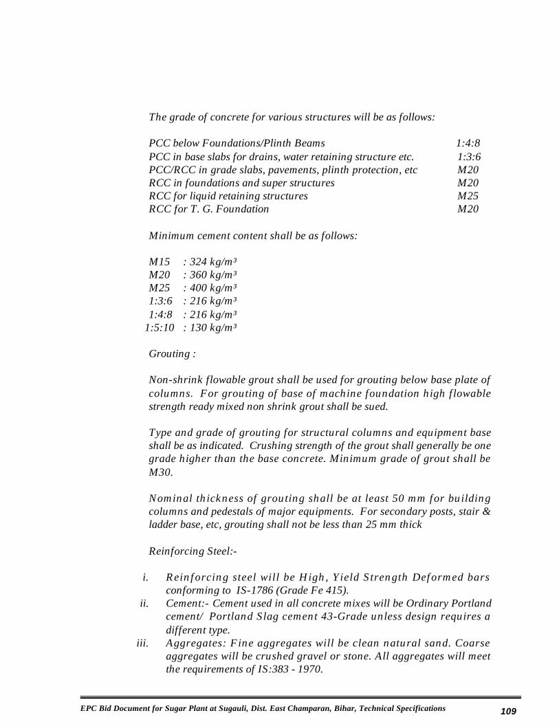
EPC Bid Document for Sugar Plant at Sugauli, Dist. East Champaran, Bihar, Technical Specifications 109
The grade of concrete for various structures will be as follows:
PCC below Foundations/Plinth Beams 1:4:8PCC in base slabs for drains, water retaining structure etc. 1:3:6PCC/RCC in grade slabs, pavements, plinth protection, etc M20RCC in foundations and super structures M20RCC for liquid retaining structures M25RCC for T. G. Foundation M20
Minimum cement content shall be as follows:
M15 : 324 kg/m³M20 : 360 kg/m³M25 : 400 kg/m³1:3:6 : 216 kg/m³1:4:8 : 216 kg/m³
1:5:10 : 130 kg/m³
Grouting :
Non-shrink flowable grout shall be used for grouting below base plate of columns. For grouting of base of machine foundation high flowable strength ready mixed non shrink grout shall be sued.
Type and grade of grouting for structural columns and equipment base shall be as indicated. Crushing strength of the grout shall generally be one grade higher than the base concrete. Minimum grade of grout shall be M30.
Nominal thickness of grouting shall be at least 50 mm for building columns and pedestals of major equipments. For secondary posts, stair & ladder base, etc, grouting shall not be less than 25 mm thick
Reinforcing Steel:-
i. Reinforcing steel will be High, Yield Strength Deformed bars conforming to IS-1786 (Grade Fe 415).
ii. Cement:- Cement used in all concrete mixes will be Ordinary Portland cement/ Portland Slag cement 43-Grade unless design requires a different type.
iii. Aggregates: Fine aggregates will be clean natural sand. Coarse aggregates will be crushed gravel or stone. All aggregates will meet the requirements of IS:383 - 1970.
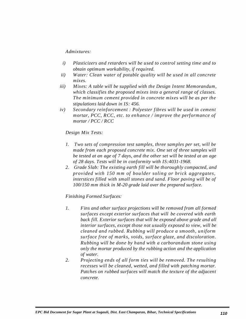
EPC Bid Document for Sugar Plant at Sugauli, Dist. East Champaran, Bihar, Technical Specifications 110
Admixtures:
i) Plasticizers and retarders will be used to control setting time and to obtain optimum workability, if required.
ii) Water: Clean water of potable quality will be used in all concrete mixes.
iii) Mixes: A table will be supplied with the Design Intent Memorandum, which classifies the proposed mixes into a general range of classes. The minimum cement provided in concrete mixes will be as per the stipulations laid down in IS: 456.
iv) Secondary reinforcement : Polyester fibres will be used in cement mortar, PCC, RCC, etc. to enhance / improve the performance of mortar / PCC / RCC
Design Mix Tests:
1. Two sets of compression test samples, three samples per set, will be made from each proposed concrete mix. One set of three samples will be tested at an age of 7 days, and the other set will be tested at an age of 28 days. Tests will be in conformity with IS:4031-1968.
2. Grade Slab: The existing earth fill will be thoroughly compacted, and provided with 150 mm of boulder soling or brick aggregates, interstices filled with small stones and sand. Floor paving will be of 100/150 mm thick in M-20 grade laid over the prepared surface.
Finishing Formed Surfaces:
1. Fins and other surface projections will be removed from all formed surfaces except exterior surfaces that will be covered with earth back fill. Exterior surfaces that will be exposed above grade and all interior surfaces, except those not usually exposed to view, will be cleaned and rubbed. Rubbing will produce a smooth, uniform surface free of marks, voids, surface glaze, and discoloration. Rubbing will be done by hand with a carborandum stone using only the mortar produced by the rubbing action and the application of water.
2. Projecting ends of all form ties will be removed. The resulting recesses will be cleaned, wetted, and filled with patching mortar. Patches on rubbed surfaces will match the texture of the adjacent concrete.

EPC Bid Document for Sugar Plant at Sugauli, Dist. East Champaran, Bihar, Technical Specifications 111
3. Plinth Protection: All buildings will be provided with 1000 mm wide and 100 mm thick plain cement concrete paving all around on the outside. The plinth protection will be laid over prepared sub-grade and base formed with broken bricks or rubble laid to a thickness of 75 mm.
Structural Elements :
Minimum thickness of structural element to be as follows:
Suspended f low s lab / roof s lab / walkways / canopy slabs, etc
: 100 mm
Ground floor slab (non-suspended) : 150 mmWater retaining slab / walls : 150 mmCable / Pipe Trenches / Under ground pit / Launder walls and base slab
: 100 mm
All footing (including raft foundation) : 250 mmTapered footing : 150 mm
(Min. at edges)
Parapets / Chajjas : 75 mmPre-cast louvers / fins : 50 mmPre-cast trench cover slabs / floor slabs / louvers
: 75 mm
Paving : 150 mmBasement walls and base slab : 150 mm
Curing:
1. Concrete will be protected from loss of moisture for not less than 7 days after the concrete is placed. Trowelled surfaces, except those that receive a separate finish or coating, will be cured with a membrane curing compound. Float finished surfaces, except those that receive a separate finish, may be cured with either a membrane-curing compound or with water. Only water curing will be used if the surface receives a separate finish.
2. Water Curing: Water saturation of concrete surfaces will begin as quickly as possible after initial set of the concrete. Water curing will begin within 12 hours in dry weather and within 24 hours in damp weather. The rate of water application will be regulated to provide complete surface coverage with a minimum of runoff The application of water may be interrupted for surface rubbing. The concrete surface will not be permitted to dry.

EPC Bid Document for Sugar Plant at Sugauli, Dist. East Champaran, Bihar, Technical Specifications 112
3. Damp proofing: Damp proof course in a thickness of 40mm and consisting of cement concrete 1:2:4 with admixture of approved water proofing compound, will be provided at plinth level for masonry walls in super structure.
4. Waterproofing: A waterproofing seal will be provided for structures where applicable. Water-proofing will be carried out by a system duly approved by the Owner/Engineer.
b) Steel
Structural Steel:-
Steel framed structures will be designed in accordance with IS:-800- Code of Practice for Construction in steel adopting allowable stress design and plastic design. In addition steel framed structures will be designed in accordance with the criteria discussed in the following subsections.
Materials:
Structural steel shapes, plates, and appurtenances for general use will conform to Indian Standards IS:800 with a minimum yield strength of 250 MPa. Connection bolts will conform to IS:-1367. Connections will conform to the latest version of the Specification for Structural Joints. Welding electrodes will be as specified by the AWS.
Tests:
Mill test reports or reports of tests made by the fabricator will be required certifying that all material is in conformance with the applicable standards and specifications. In addition, the fabricator will provide an affidavit stating that all steel specified has been provided at yield stresses in accordance with the drawings and the specification.
Minimum Heights for pedestals of Steel Columns :
Top of RCC foundation (pedestals) shall normally be kept at a height of 300 mm above the floor level.
Other Pedestals and Foundations
Stairs and ladder pedestal : 200 mm above the finished floor level
Equipment in open area : As required (300 mm min.)Equipment in covered area : As required (150 mm min.)

EPC Bid Document for Sugar Plant at Sugauli, Dist. East Champaran, Bihar, Technical Specifications 113
Structures / Equipment supplied : As per vendors data subject to minimum as specified above
In case the top of pedestal is kept at a lower level so that the column base plates together with gussets and stiffener remains below finished floor level (FFL), the column base as well as column section shall be encashed in concrete above FFL as below:
Open area : 300 mm above FPL / FGL, whichever is higherCovered : 150 mm above the FFL
c) Miscellaneous Metal Items
Steel Grating:
Steel gratings will be pressure locked grating manufactured with 40mmx 5mm MS strips as longitudinal bearing strips (spanning the supports) and 25mm x 3mm strips in transverse direction. The grating will be provided with a 40mm x 5mm band all-round. The grating will be designed for 500kg/m2 loading and spans up to 1500mm. Stair treads will also be made of steel grating with nosing.
Guard rail /Handrail:
Guard rail will be a two-rail system with the top rail 1000 mm above the walkway surface and the intermediate rail 500 mm below the top rail. Guard rail post spacing will be proportioned to the length of the protected horizontal opening, but will not exceed 1200mm centre-to-centre of posts. Guard rail will be shop fabricated for specific locations and field welded or bolted to the erected structural steel. Steel pipe will conform to IS-1151, Medium grade.
Anchor Bolts and Embedded Shapes:
Anchor bolts will conform to IS:-5624. Embedded shapes and plates will be galvanized where required. Anchor bolt assemblies will be galvanized where required. Steel, which is not galvanized and will remain exposed, will be primed with a primer paint.

EPC Bid Document for Sugar Plant at Sugauli, Dist. East Champaran, Bihar, Technical Specifications 114
d) Data to be submitted by Contractor with the bid
The Contractor to submit the integrated sugar plant layout and sections, cross-section, elevation, GA, layout for the housing areas, all plant and non-plant buildings, layouts for the cooling systems, designs for the water supply schemes etc., layout and sections for the effluent disposal and the schemes for the same, areas designated for the marshalling and cane yards, nursery, the bagasse handling system schemes etc. Contractor to also reflect water collection schemes, water harvesting schemes, collection systems etc. Landscaping details shall also be reflected by the Contractor on the layout. Contractor shall also reflect provisions for future expansion for all sections. The Contractor to also submit the sizes considered for all buildings in the scope.
8.2.11 Effluent Treatment Plant
The sugar project will have its own effluent treatment plant. Effluent will be discharged by the Contractor at identified exits of the integrated plant area. The discharged effluent will be oil free and meet or better the BPCB norms. Part of the treated effluent will be pumped back to the Contractor to be utilized for ash quenching and gardening in the integrated plant area. The ETP will include the required storage area, aerators, dosing systems, sludge drying beds, etc. based on the expected effluent quality and BPCB norms. The expected quantity of effluent is to be detailed by the Contractor.
8.3 Buildings & Civil Works
8.3.1 Cane Yard, Marshalling Yard
The cane and marshalling yard for required number of vehicles shall be properly developed for the heavy traffic expected. Cane Yard shall be concrete topped/paved and the marshalling yard shall be leveled and shall be properly planned for proper and easy movement of the vehicles, bullock carts etc. Provision of area for housing the seasonal labor shall be made in the marshalling yard along with provisions for providing the numbering slips etc.

EPC Bid Document for Sugar Plant at Sugauli, Dist. East Champaran, Bihar, Technical Specifications 115
8.3.2 Internal Roads & Culverts
Internal roads in sugar plant area shall be concrete/bitumen topped of sufficientwidths as required, one way/two way with proper street lighting arrangements and green zone/plantation in the centre/ along the sides, with proper road side drains, culverts, provision of pipes/ducts to carry storm water in separate ducts and cables/pipes in separate ducts. Crossings, cul-de-sacs and dead ends shall be properly planned for and provided. No roads shall be less than 6m in width. Roads shall follow the specifications provided with the tender documents. The joining of internal roads with common roads and roads within other plants will be suitably co-ordinated.
8.3.3 Fencing & Gates
Fencing for the sugar factory and non plant buildings shall be as required for the excisable limits with openings as required by excise norms. Fencing shall be masonry wall up to 600mm above NGL with barbed wire/chain link fencing above and of a minimum height of 2.1m above NGL. “Y” shaped angles with barbed wire rounds shall be provided at the top of the fencing necessarily. Gates to be sliding type electrically operated and all gates to have provision of man gates within the gates. Gates shall be minimum 2m height. Gates shall be of various widths as per requirement, however not less than 6m in width.
8.3.4 Culverts, Side Drains, Storm Water Drains
Drains and culverts shall be designed as per requirements and as specified in the other sections. Side water drains and storm water drains shall be connected to the water harvesting scheme. Proper provisions shall be carried out especially at crossings, cable crossings etc. Drains shall as far as possible be trough type RCC, with sufficient depths and proper slopes in conjunction with the total scheme worked out for the site. Pipes for drains could also be used with provision for proper inspection and maintenance at regular intervals. As far as possible, drains and cable trenches shall not be planned side by side. The hook ups for storm drains with common drains and drains within other plant areas will be suitably co-ordinated.
8.3.5 Diffusion Juice Extraction Plant
The Diffusion Extraction Plant/building (only if necessary) is approximately 25.0 meters wide x 50.00 meters long x 15.0 eaves height with sloped roof. The building (if required) is designed to be a structural frame building with no interior building column and the exterior wall columns shall also serve as crane columns for the overhead traveling crane in the building. Crane beams and crane rails shall be installed on the wall columns. The roof shall either be either of truss or

EPC Bid Document for Sugar Plant at Sugauli, Dist. East Champaran, Bihar, Technical Specifications 116
single beam rafter construction. Adequate bracing is to be provided on all sides and roof of the building for wind and equipment loads.
The building will have metallic siding for the roof and walls and translucent fiberglass panels shall be provided as sky lights in the roof and a light band (vertical/horizontal as required) around the perimeter of the building. The metallic siding shall extend down to within 5 meters of grade and the remaining 5 meters shall be brick masonry/concrete block with louver panels installed. The roof is to be provided with a 2 meter wide gravity vent to insure adequate natural ventilation of the building during operation and in the out of crop season.
A brick masonry/concrete block electrical equipment room shall be built on the side of the Building on which the electric motor drive controls are installed. The floor height of the building shall be such that personnel can walk from the equipment to the electrical equipment room without having to go up or downstairs. The room shall be air conditioned.
Flooring shall be checkered plate for all working platforms and rcc/pcc flooring vaccum dewatering system.
8.3.6 Boiling House Building
The Boiling House Building will house the following process areas:
Evaporator and Heaters 30m x 60m x 23m Ht.Vacuum Pans, Centrifugals 60m x 60m x 27m Ht.Sugar Dryer, Sugar Silos, Sugar Bagging 30m x 42m x 30m Ht.Tool and Spare Parts Room, Panel RoomTime Keeper’s Office, Central Control Panel RoomArea as required
Overall, the Boiling House Building is approximately as dimensioned above with eave height with sloped roof. The building is designed to be a structural frame building with no interior building columns. Equipment inside the building shall be supported on independent structural columns that are connected to the side wall columns but do not extend to the roof. The roof shall either be either of truss or single beam rafter construction. Adequate bracing is to be provided on all sides and roof of the building for wind and equipment loads.
The building will have metallic siding for the roof and walls and translucent fiberglass panels shall be provided as sky lights in the roof and a light band (vertical/horizontal as required) around the perimeter of the building. Where possible the side wall panels will align with those of the Diffusion Plant Building. The metallic siding shall extend down to within 5 meters of grade and the remaining 5 meters shall be brick masonry/concrete block with louver panels

EPC Bid Document for Sugar Plant at Sugauli, Dist. East Champaran, Bihar, Technical Specifications 117
installed. The roof is to be provided with a 2 meter wide gravity vent to insure adequate natural ventilation of the building during operation and in the out of crop season.
Flooring shall be checkered plate for all working platforms and rcc/pcc flooring vaccum dewatering system.
A b rick masonry/concrete block wall shall be installed to separate the Evaporator/Vacuum Pan area of the building from the Dry Sugar Handling area, Sugar Drying and Bagging areas, to reduce contamination of sugar from dust emanating from the Building and to contain sugar dust in one area which will make it easier to reclaim sugar. In the event of a sugar dust explosion, the wall should mitigate the blast wave into the rest of the Boiling House Building.
A brick masonry/concrete block with RCC slab, Electrical Equipment Room shall be incorporated into the building to house the drives and motor starters for the “A”, “B” and “C” centrifugals, which will be air conditioned.
8.3.7 Clarifier & Filter Building
The Clarifier building shall be approximately 16.0 meters wide x 60.0 meters long x 17.0 meter eave height, the Vaccum Filter building 18m x 36m x 17m eave height, the sulphur burner building 12m x 24m x 17m eave height, the lime station 18m x 24m x 17m eave height, sulphitors building 6m x 24m x 17m height, and all buildings shall be structural framed building with metallic roofing and partial siding. The Clarified Juice Tank, Sulphited Juice and Syrup Tanks and associated pumps, and Lime Preparation Equipment shall be installed at grade or on intermediate structures. Sulphur Burners shall be installed at the 8,000 MM elevation on one side of the building and shall be separated from the Rotary Vacuum Filters and Juice/Syrup Sulphitation equipment by a concrete block wall.
A concrete floor shall be provided for the sulphur burners. This area shall be covered by the roof but siding will not be installed around the burners or the lime preparation equipment below. Siding will be carried to within 5 meters of grade on the side of the building that encloses the juice pumps and storage tanks. The remaining 5 meters shall be brick masonry/concrete block with louvers. That portion of the building, approximately 50%, housing the sulphur burners and lime preparation equipment will not be sided. Elevated flooring around the Filter Station shall be checkered plate Columns on one end of the building and shall be designed to support half the load of the Mud Storage Bin.

EPC Bid Document for Sugar Plant at Sugauli, Dist. East Champaran, Bihar, Technical Specifications 118
8.3.8 Chemical Stores Building
The Chemical Storage Building shall be a concrete block building approximately 7.0 meters wide x 18.0 meters long x 5.0 meter eave height with sloping metallic roof. The building shall be divided into three separate storage areas, one each for bagged sulphur, bagged or drummed caustic soda and bulk burnt limestone. Manual rollup doors will be provided for the two storage areas for sulphur and caustic soda, the limestone storage area will have a full width opening. Brick Masonry/Concrete block walls shall extend up to the roof in each area and a gravity vent shall extend the length of the apex of the roof.
8.3.9 Sugar Godown / Bagged Sugar Warehouse
The Bagged Sugar Warehouses shall be a free span portal frame of rigid frame design building with no internal columns with approximate dimensions of 70 meters wide x 90 meters long x 8.00 meter eave height and a sloping/curved roof. The buildings shall be designed to store 15000 tons of 50 kg bags of sugar with ample allowance for aisles and stand off from walls. Two end bays on one side of the building shall be reserved for unloading bags from the two bagged sugar conveyors. The building will have metallic siding for the roof or self supporting galvalume sheet roofing and walls and translucent fiberglass panels shall be provided as sky lights in the roof and a light band around the perimeter of the building. Where possible, the translucent side wall panels will align with those of the Diffusion Plant Building and Boiling House. The metallic siding shall extend down to within 5 meters of grade and the remaining 5 meters shall be brick masonry/concrete block. The roof is to be provided with a 2 meter wide gravity vent to ensure adequate natural ventilation of the building during operation and in the out of crop season.
The building shall be provided with six rollup doors, manual operated, 4.5 meters x 4.5 meters and six man doors with locks and emergency exit bars. Three meter canopies shall be provided over each rollup door.
8.3.10 Machine Shop Building
Shall be approximately 20 meters wide x 25 meters long x 8 meter eave height with sloped roof. The building could be adjacent to the sugar plant. The building is designed to be a structural frame building with one line of interior columns that shall serve as a crane column for the 20 meter span overhead traveling crane on the building. Crane beams and crane rails shall be installed on wall columns. The roof shall be either of truss or single beam rafter construction. Adequate bracing is to be provided on all sides and roof of the building for wind and equipment loads.

EPC Bid Document for Sugar Plant at Sugauli, Dist. East Champaran, Bihar, Technical Specifications 119
The building will have metallic siding for the roof and walls and translucent fiberglass panels shall be provided as sky lights in the roof and a light band around the perimeter of the building. The metallic siding shall extend down to within 5 meters of grade and the remaining 5 meters shal l be brick masonry/concrete block with louver panels installed. The roof is to be provided with a 2 meter wide gravity vent to ensure adequate natural ventilation of the building during operation and in the out of crop season.
The building shall have inbuilt racks for storage of materials, files etc. and a closed room for the In-Charge with slab at 3m lvl. for the closed room.
Two roll up doors, 4.5 meters x 4.5 meters, manually operated shall be providedat locations to be determined during the design phase. A minimum of two man doors shall also be provided with emergency hardware.
8.3.11 Security, Time, Excise & Allied Offices, Ambulance Room, Fire Fighting Tender Shed Etc.
The security cabin at the entrance shall be RCC roof with brick/block masonry walls and an ambulance room along with the shed for the fire fighting tender shall be provided at the entrance. Time, excise and allied offices shall however be provided near the common control panel room area in the boiling house along with the worker’s rest room, toilet facilities etc. The building shall have aluminium doors and windows, spartek or equivalent flooring and good finishes on the exterior and interiors. The rooms may be air conditioned. The building and the rooms shall be sound proof if provided within the factory building area and proper doors and windows shall be planned for the same.
The EPC Contractor shall also include in his bid erect ion of proper security/inspection turrets in RCC/Structural Steel at all corners of the plot and as identified by the Client/Client Consultant for security and watch. All such turrets shall have provision of protection from rains, wind and heat and facility for proper inspection.
8.3.12 Canteen Building
Proper canteen and facilities shall be provided for the management, workers and the staff of the integrated plant. Proper segregation for the officer’s, the workers, the labor and others shall also be planned for in the canteen building and the canteen building may be placed at any suitable location. Canteen shall cater to all the personnel connected with the integrated plant including the visitor’s and guests to the plant area.
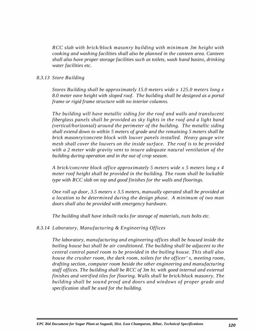
EPC Bid Document for Sugar Plant at Sugauli, Dist. East Champaran, Bihar, Technical Specifications 120
RCC slab with brick/block masonry building with minimum 3m height with cooking and washing facilities shall also be planned in the canteen area. Canteen shall also have proper storage facilities such as toilets, wash hand basins, drinking water facilities etc.
8.3.13 Store Building
Stores Building shall be approximately 15.0 meters wide x 125.0 meters long x 8.0 meter eave height with sloped roof. The building shall be designed as a portal frame or rigid frame structure with no interior columns.
The building will have metallic siding for the roof and walls and translucent fiberglass panels shall be provided as sky lights in the roof and a light band (vertical/horizontal) around the perimeter of the building. The metallic siding shall extend down to within 5 meters of grade and the remaining 5 meters shall be brick masonry/concrete block with louver panels installed. Heavy gauge wire mesh shall cover the louvers on the inside surface. The roof is to be provided with a 2 meter wide gravity vent to insure adequate natural ventilation of the building during operation and in the out of crop season.
A brick/concrete block office approximately 5 meters wide x 5 meters long x 4 meter roof height shall be provided in the building. The room shall be lockable type with RCC slab on top and good finishes for the walls and floorings.
One roll up door, 3.5 meters x 3.5 meters, manually operated shall be provided at a location to be determined during the design phase. A minimum of two man doors shall also be provided with emergency hardware.
The building shall have inbuilt racks for storage of materials, nuts bolts etc.
8.3.14 Laboratory, Manufacturing & Engineering Offices
The laboratory, manufacturing and engineering offices shall be housed inside the boiling house but shall be air conditioned. The building shall be adjacent to the central control panel room to be provided in the boiling house. This shall also house the crusher room, the dark room, toilets for the officer’s, meeting room, drafting section, computer room beside the other engineering and manufacturing staff offices. The building shall be RCC of 3m ht. with good internal and external finishes and vetrified tiles for flooring. Walls shall be brick/block masonry. The building shall be sound proof and doors and windows of proper grade and specification shall be used for the building.

EPC Bid Document for Sugar Plant at Sugauli, Dist. East Champaran, Bihar, Technical Specifications 121
8.3.15 Weigh Bridge Cabins
Weigh bridge cabin each of size 5m x 5m x 3m shall be provided at the cane entrance near the weigh bridges. The structure shall be RCC slab, brick/block masonry, aluminium doors and windows, industrial flooring, inbuilt rack facilities for record storage, ease of operation for recording and issuing necessary slips etc. A separate cabin shall be provided for each weigh bridge, which shall however be connected by networking facilities to each other. Sufficient storage space for records shall be provided.
8.3.16 Toilet Blocks
Proper sanitary facilities as per factory norms shall be provided inside the fenced area for the workers, the staff and the management. The scope shall cover all the plumbing, sanitation etc. required for the toilet blocks at all locations. Separate toilet facilities shall be provided for male and female both. Toilet blocks shall be RCC slab, brick/block masonry structure with glazed tile flooring and dado upto the ceiling levels, with proper ventilated areas, W.C’s, wash hand basins, shower areas, urinals, bidets etc. All sanitary and plumbing shall be concealed type and of 1st quality only.
8.3.17 Spray Pond, Water Channels & Pump House
Spray Pond of required size and capacity shall be provided for the integrated plant. The structure could be masonry/rcc structure including for the water channels. Required pump house with gantry facilities shall be provided adjacent to the spray pond/cooling tower. Epoxy waterproofing shall be adopted for the water holding areas and the structures shall be made fully water-proof. Spray pond/cooling tower shall be designed for minimum dead water storage and if the site permits, table top spray pond design shall be adopted. Proper levels and slopes shall be maintained at all locations. Location and orientation of the spray pond shall be such as to provide maximum contact with wind or to provide proper natural aeration.
8.3.18 All Machinery & Other Equipment etc. Foundations
Machinery foundations suitable for the machinery equipment loadings suitable for the 3500 TCD capacity plant and machinery including all major and minor foundations shall be included in the offer of the EPC Contractor. The foundations could broadly be identified as :-
x Diffusion Plant foundationsx Cane handling foundationsx Boiling house foundations

EPC Bid Document for Sugar Plant at Sugauli, Dist. East Champaran, Bihar, Technical Specifications 122
x Sugar house foundationsx Clarification house foundationsx All major and minor foundations for 3500 TCD plant and machineryx All pumps, compressors, d.g.set foundationsx Injection Condensate water channelsx Weigh bridge foundationsx Machine shop lathe etc. foundationsx Bagasse carrier, elevators etc. foundations
8.3.19 Cable Trenches/Water Drains Etc.
Cable trenches will be rectangular reinforced concrete structures of approx. 1m width and 1m depth (sizes may vary as per sections and houses). They will be covered either by pre-cast concrete covers or by chequered plate covers. Cable pull pits of approx. 1x1x2m deep will be provided at suitable locations.
All paved and unpaved surface in the power plant area will be adequately drained with drainage system for rain water/ fire water/ washing water. Open surface drains will be provided with bricks of class designation 50 or locally good quality brick in cement mortar 1:4 including 100 mm thick bed concrete of grade 1:3:6 and 12 mm thick cement plaster 1:4 with a floating coat of neat cement inside the drains without any cover. Manholes will be made of reinforced concrete and contain silt traps. Storm water drains will collect all surface water from roofs of the buildings and from paved and unpaved areas as applicable. The drains from proposed plant area will be connected to the main drains running all along the roads.
8.3.20 Effluent Treatment Plant
Effluent treatment plant of suitable capacity for the integrated plant comprising of baby and oil trap, oil and grease trap, aeration tanks, primary and secondary clarifiers, equilisation tanks, holding tanks, sand filters, flocculation tank, cleaning day tank, sludge drying beds including all pipes lines in UPVC/HDPE and/or structures as required as per the effluent disposal systems could be in masonry/rcc structure. Details of the scheme shall be submitted along with the bid proposal. Effluent treatment plant location and disposal of treated effluent will be as laid down in other parts of the specifications.
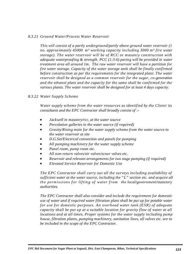
EPC Bid Document for Sugar Plant at Sugauli, Dist. East Champaran, Bihar, Technical Specifications 123
8.3.21 Ground Water/Process Water Reservoir
This will consist of a partly underground/partly above ground water reservoir (1 no. approximately 45000 m³ working capacity including 3000 m³ fire water storage). The water reservoir will be of RCC or masonry construction with adequate waterproofing & strength. PCC (1:3:6) paving will be provided in water treatment area all around 1m. The raw water reservoir will have a partition for fire water storage. Capacity of the water storage tank shall be finally confirmed before construction as per the requirements for the integrated plant. The water reservoir shall be designed as a common reservoir for the sugar, co-generation and the ethanol plant and the capacity for the same shall be confirmed for the various plants. The water reservoir shall be designed for at least 4 days capacity.
8.3.22 Water Supply Scheme
Water supply scheme from the water resources as identified by the Client/ its consultants and the EPC Contractor shall broadly consist of :-
x Jackwell in masonry/rcc, at the water sourcex Percolation galleries in the water source (if required)x Gravity/Rising main for the water supply scheme from the water source to
the water reservoir at sitex D.G.Set/Electrical connection and panels for pumpingx All pumping machinery for the water supply schemex Panel room, pump room etc.x All non-return valves/air valves/scour valves etc.x Reservoir and relevant arrangements for two stage pumping (if required)x Elevated Service Reservoir for Domestic Use
The EPC Contractor shall carry out all the surveys including availability of sufficient water at the water source, including the “L” section etc. and acquire all the permissions for l if t ing of water from the local/government/statutory authorities.
The EPC Contractor shall also consider and include the requirement for domestic use of water and if required water filtration plant shall be put up for potable water for use for domestic purposes. An overhead water tank (ESR) of adequate capacity shall be put up at a suitable location for gravity flow of water at all locations and at all times. Proper systems for the water supply including pump house, filtration plants, pumping machinery, sanitation lines, all valves etc. are to be included in the scope of the EPC Contractor.
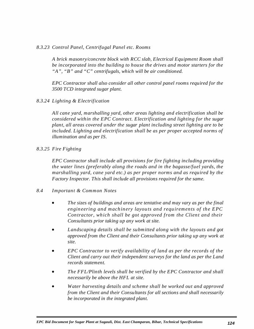
EPC Bid Document for Sugar Plant at Sugauli, Dist. East Champaran, Bihar, Technical Specifications 124
8.3.23 Control Panel, Centrifugal Panel etc. Rooms
A brick masonry/concrete block with RCC slab, Electrical Equipment Room shall be incorporated into the building to house the drives and motor starters for the “A”, “B” and “C” centrifugals, which will be air conditioned.
EPC Contractor shall also consider all other control panel rooms required for the 3500 TCD integrated sugar plant.
8.3.24 Lighting & Electrification
All cane yard, marshalling yard, other areas lighting and electrification shall be considered within the EPC Contract. Electrification and lighting for the sugar plant, all areas covered under the sugar plant including street lighting are to be included. Lighting and electrification shall be as per proper accepted norms of illumination and as per IS.
8.3.25 Fire Fighting
EPC Contractor shall include all provisions for fire fighting including providing the water lines (preferably along the roads and in the bagasse/fuel yards, the marshalling yard, cane yard etc.) as per proper norms and as required by the Factory Inspector. This shall include all provisions required for the same.
8.4 Important & Common Notes
x The sizes of buildings and areas are tentative and may vary as per the final engineering and machinery layouts and requirements of the EPC Contractor, which shall be got approved from the Client and their Consultants prior taking up any work at site.
x Landscaping details shall be submitted along with the layouts and got approved from the Client and their Consultants prior taking up any work at site.
x EPC Contractor to verify availability of land as per the records of the Client and carry out their independent surveys for the land as per the Land records statement.
x The FFL/Plinth levels shall be verified by the EPC Contractor and shall necessarily be above the HFL at site.
x Water harvesting details and scheme shall be worked out and approved from the Client and their Consultants for all sections and shall necessarily be incorporated in the integrated plant.

EPC Bid Document for Sugar Plant at Sugauli, Dist. East Champaran, Bihar, Technical Specifications 125
x Sites in possession of the Archeological department shall be identified and shall be protected and maintained in proper manner as per the Statutory norms of the Archeological Department.
x Places of worship within the site need to be identified and shall be properly protected and maintained at all locations. The layout shall reflect all such locations and the means of protection to be adopted for these locations.
8.5 The construction specifications have been given in Appendix - XI.

EPC Bid Document for Sugar Plant at Sugauli, Dist. East Champaran, Bihar, Technical Specifications 126
Chapter – 9
Spares
The spares required for erection & commissioning will be made available by the appointed EPC contractor. Essential spares required for 2 years of operation as per Appendix - XII will be provided in the EPC bid price.

EPC Bid Document for Sugar Plant at Sugauli, Dist. East Champaran, Bihar, Technical Specifications 127
Chapter – 10
Inspection & Testing
The Contractor will submit Quality Assurance Plan (QAP) and inspection schedule for the equipment covered in this bid for approval, within 15 days of Letter of Intent (LoI). The Owner or representatives of the Owner will attend these inspections at the Contractor’s or sub-contractor’s works and / or give waiver.

EPC Bid Document for Sugar Plant at Sugauli, Dist. East Champaran, Bihar, Technical Specifications 128
Chapter – 11
Drawings, Data & Information
The Contractor will submit list of documents, data & drawings to the Owner for the equipment covered under this section, defining the category like approval or information, within 15 days of LoI. The Owner or representatives will approve the list accordingly.
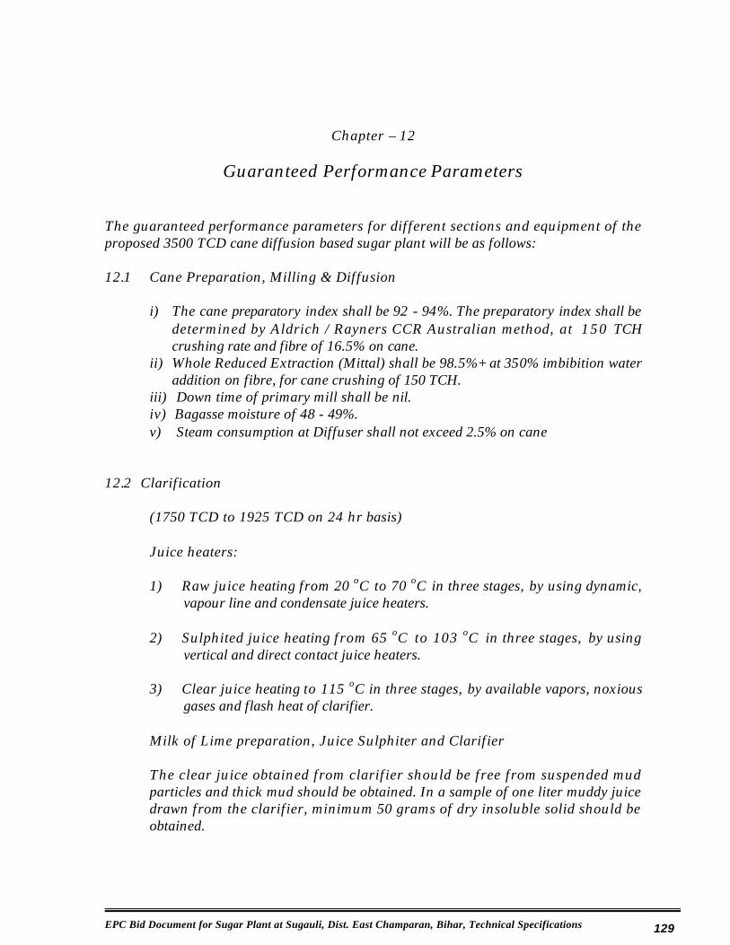
EPC Bid Document for Sugar Plant at Sugauli, Dist. East Champaran, Bihar, Technical Specifications 129
Chapter – 12
Guaranteed Performance Parameters
The guaranteed performance parameters for different sections and equipment of the proposed 3500 TCD cane diffusion based sugar plant will be as follows:
12.1 Cane Preparation, Milling & Diffusion
i) The cane preparatory index shall be 92 - 94%. The preparatory index shall be determined by Aldrich / Rayners CCR Australian method, at 150 TCH crushing rate and fibre of 16.5% on cane.
ii) Whole Reduced Extraction (Mittal) shall be 98.5%+ at 350% imbibition water addition on fibre, for cane crushing of 150 TCH.
iii) Down time of primary mill shall be nil.iv) Bagasse moisture of 48 - 49%. v) Steam consumption at Diffuser shall not exceed 2.5% on cane
12.2 Clarification
(1750 TCD to 1925 TCD on 24 hr basis)
Juice heaters:
1) Raw juice heating from 20 oC to 70 oC in three stages, by using dynamic, vapour line and condensate juice heaters.
2) Sulphited juice heating from 65 oC to 103 oC in three stages, by using vertical and direct contact juice heaters.
3) Clear juice heating to 115 oC in three stages, by available vapors, noxious gases and flash heat of clarifier.
Milk of Lime preparation, Juice Sulphiter and Clarifier
The clear juice obtained from clarifier should be free from suspended mud particles and thick mud should be obtained. In a sample of one liter muddy juice drawn from the clarifier, minimum 50 grams of dry insoluble solid should be obtained.

EPC Bid Document for Sugar Plant at Sugauli, Dist. East Champaran, Bihar, Technical Specifications 130
Vacuum Filter
Vacuum filter efficiency (mud solids retention) should be not less than 75% based on the average of 6 samples taken under regular working conditions. The bagacillo should be available at the rate of 9.00 Kgs per tone of cane per hour; pol % filter cake should be not more than 1.00% at wash water of 100% on cake.
12.3 Evaporation & Boiling Section
(1750 TCD to 1925 TCD on 24 hr basis)
Evaporator
(i) Minimum vacuum at the last body of evaporator 600-635 mm.(ii) The evaporator set to give up to 85% + evaporation.(iii) Two separate sets to achieve non-stop season throughout run.
Syrup Sulphiter
The syrup sulphiter capable of sulphiting the syrup of 5 pH.
Vacuum Pan
(i) Minimum vacuum at the pan body of 625-635 mm.(ii) Total cycle time (with full strike level) not more than the following:
A massecuite pan - 2.5 hours to 3.00B massecuite pan - 4.0 hoursC massecuite pan - 8.0 hours after footing and C – massecuite brix 101 deg.
Condensers
(i) Minimum vacuum in the body of the condenser of 650 mm. The water to vapour ratio of 26 average and 30 max.
(ii) Temperature difference between vapours to be condensed and tail pipe water temperature less than 10 oC.
Spray Pond
Minimum drop of 13 oC or within 7 oC of wet bulb temperature for injection water cooling during season.
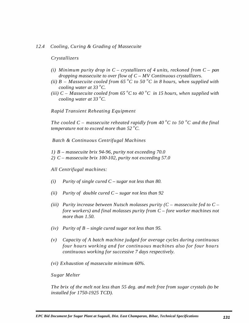
EPC Bid Document for Sugar Plant at Sugauli, Dist. East Champaran, Bihar, Technical Specifications 131
12.4 Cooling, Curing & Grading of Massecuite
Crystallizers
(i) Minimum purity drop in C – crystallizers of 4 units, reckoned from C – pan dropping massecuite to over flow of C – MV Continuous crystallizers.
(ii) B – Massecuite cooled from 65 oC to 50 oC in 8 hours, when supplied with cooling water at 33 oC.
(iii) C – Massecuite cooled from 65 oC to 40 oC in 15 hours, when supplied with cooling water at 33 oC.
Rapid Transient Reheating Equipment
The cooled C – massecuite reheated rapidly from 40 oC to 50 oC and the final temperature not to exceed more than 52 oC.
Batch & Continuous Centrifugal Machines
1) B – massecuite brix 94-96, purity not exceeding 70.02) C – massecuite brix 100-102, purity not exceeding 57.0
All Centrifugal machines:
(i) Purity of single cured C – sugar not less than 80.
(ii) Purity of double cured C – sugar not less than 92
(iii) Purity increase between Nutsch molasses purity (C – massecuite fed to C –fore workers) and final molasses purity from C – fore worker machines not more than 1.50.
(iv) Purity of B – single cured sugar not less than 95.
(v) Capacity of A batch machine judged for average cycles during continuous four hours working and for continuous machines also for four hours continuous working for successive 7 days respectively.
(vi) Exhaustion of massecuite minimum 60%.
Sugar Melter
The brix of the melt not less than 55 deg. and melt free from sugar crystals (to be installed for 1750-1925 TCD).

EPC Bid Document for Sugar Plant at Sugauli, Dist. East Champaran, Bihar, Technical Specifications 132
Grass Hopper
The temperature of the sugar at the end of the last hopper not more than 42 oC and moisture not more than 0.03%, when the ambient temperature is below 36°C.
12.5 Reduced Boiling House Recovery
The reduced boiling house recovery not less than 91.5% by Gundu Rao formula.
12.6 Steam Consumption
Steam consumption of the entire sugar plant not more than 22% on cane. Medium pressure steam not to be used for any purposes in the operating sugar plant, but kept as standby provision for start up purposes.
12.7 Power Consumption
1) Operating electrical power consumption of the entire cane preparation, diffusion section and sugar boiling process house not to exceed 19 kWh/TCH x 150 TCH or 2850 kW.
2) The power factor of the electrical system not less than 0.95; 3) The performance of all electrical equipments as per existing IS: codes.
12.8 Performance Trial Period
At the time of performance trials, the HPCL management should, besides giving assistance as per agreement, also arrange adequate supply of clean, sufficient and continuous cane of 3500 TCD or 150 TCH for 10-days period, conforming to the following specifications so that the performance trials get completed smoothly:
Sr. No. Item Value 1. Crushing rate 150 TCH or 3500 TCD on 24
hr basis 2. Fibre % cane Not more than 173. Pol % cane Not less than 11.54. Mixed Juice Purity, % Not less than 80
Performance trials to be carried out for the continuous period of 10 days, during the period of January and February.

EPC Bid Document for Sugar Plant at Sugauli, Dist. East Champaran, Bihar, Technical Specifications 133
12.9 Input & out put flow rates
(50-55% mixed juice to be sent to ethanol plant and remaining 45-50% mixed juice to be sent to Sugar Processing House)
Inputs:
Sr. No. Material Flow Rate, for 150 TCH 1. Sugar cane: 3500 TCD or 150 TCH2. Imbibition water: 40-50% cane or 1400-1750 MT/day or 60-88
MT/hour3. Steam % cane: 22 or 792 MT/ day or 33 MT/ hour4. Electrical Power: 19 kWh/TCH or 2850 KW5. G. S. Water: 1800 cu.m /day or 75 cu.m /hr
Outputs:
Sr. No. Material Flow Rate, for 150 TCH 1. Screened &
measured mixed juice
110% on cane or 3850 MT/day or 165 MT/hour.(50% mixed juice to be sent directly to Ethanol plant or 1925 MT/day or 82 MT/hr and 50% mixed juice to be sent to Sugar plant or 1925 MT/day or 83 MT/hr)
2. Bagasse Moisture 48 to 49% and pol 1-1.25%, the bagasse shall be sent to cogeneration power plant, at 3500 TCD x 33 -34% bagasse on cane or 1155-1190 MT/day
3. High quality exhaust condensate
To cogen power plant at 576 MT/day or 24 MT/hr
4. Plantation white Sugar
10% recovery on cane x 1750 TCD or 175 MT /dayor 7.50 MT/hour
5. Molasses 4.85% on cane x 1750 TCD or 85 MT/day or 3.55MT/ hour, to be sent to the Ethanol plant
6. Filter cake 2.5-3% on cane x 1750 TCD or 44 MT/day or 1.825 MT/hr, to be sent for composting of spent wash from ethanol plant
7. Effluent water discharge
Nominal, near to zero
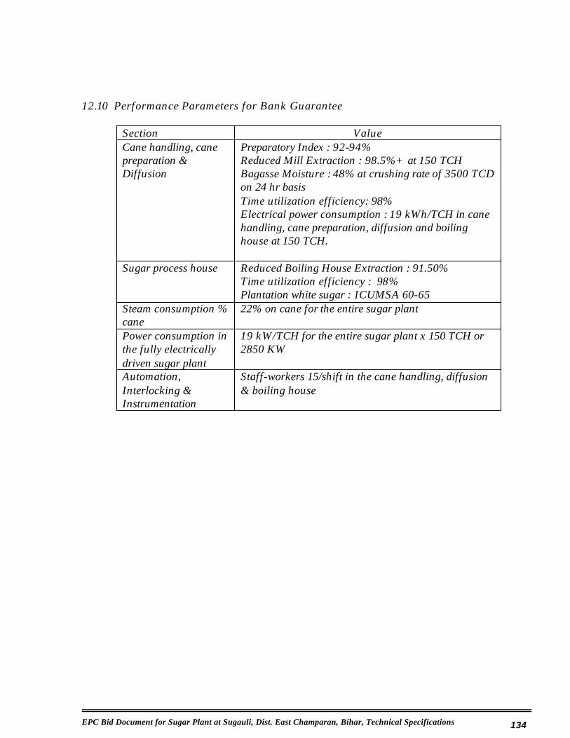
EPC Bid Document for Sugar Plant at Sugauli, Dist. East Champaran, Bihar, Technical Specifications 134
12.10 Performance Parameters for Bank Guarantee
Section Value Cane handling, cane preparation & Diffusion
Preparatory Index : 92-94%Reduced Mill Extraction : 98.5%+ at 150 TCHBagasse Moisture : 48% at crushing rate of 3500 TCD on 24 hr basisTime utilization efficiency: 98%Electrical power consumption : 19 kWh/TCH in cane handling, cane preparation, diffusion and boiling house at 150 TCH.
Sugar process house Reduced Boiling House Extraction : 91.50%Time utilization efficiency : 98%Plantation white sugar : ICUMSA 60-65
Steam consumption % cane
22% on cane for the entire sugar plant
Power consumption in the fully electrically driven sugar plant
19 kW/TCH for the entire sugar plant x 150 TCH or 2850 KW
Automation, Interlocking & Instrumentation
Staff-workers 15/shift in the cane handling, diffusion & boiling house