Embed Size (px)
Citation preview

MAHAVITARAN INFRASTRUCTURE PLAN TECHNICAL SPECIFICATION - 37
MAHARASHTRA STATE ELECTRICITY DISTRIBUTION COMPANY LTD. PAGE 1 OF 29
TECHNICAL SPECIFICATION
FOR
11 kV 25 KA INDOOR SWITCHGEAR
INTEGRATED WITH ASSOCIATED CONTROL AND RELAY PANELS
AND
CONTROL DESK FOR REMOTE OPERATION
FOR
VARIOUS 33/11 KV SUBSTATIONS
( SPECIFICATION NO.DIST/MM/05/2006 )

MAHAVITARAN INFRASTRUCTURE PLAN TECHNICAL SPECIFICATION - 37
MAHARASHTRA STATE ELECTRICITY DISTRIBUTION COMPANY LTD. PAGE 2 OF 29
SPECIFICATION FOR 11KV 25 kA INDOOR SWITCHGEAR INTEGRATED WITH CONTROL AND RELAY PANELS AND CONTROL DESK FOR REMOTE OPERATIONS
1.0 SCOPE: 1.1. This Specification covers the basic requirements in respect of 11 kV, 25 kA (with
highest system voltage of 12 kV) indoor switchgear integrated with associated indoor control and relay panels for installation at various sub-stations in Maharashtra. Clause 5 of the Specification covers the requirements of indoor switchgear with relays & controls. The control and relay panel should form integral part of the switchgear (i.e. should be physically integrated into one unit). In addition to this an operator's supervisory control desk should be provided having facility of remote closing, tripping of every switchgear panel and a repeat annunciation and indication system showing status of the circuit breaker.
1.2. The equipment offered shall be complete with all parts necessary for their effective and trouble-free operation. Such parts will be deemed to be within the scope of the supply irrespective of whether they are specifically indicated in the commercial order or not.
1.3. The respective drawing alongwith notes and specification attached hereto form an integral part of this specification for all purposes.
1.4. It is not the intent to specify herein complete details of design and construction. The equipment offered shall conform to the relevant standards and be of high quality, sturdy, robust and of good design and workmanship complete in all respects and capable to perform continuous and satisfactory operations in the actual service conditions at site and shall have sufficiently long life in service as per statutory requirements. In actual practice, not withstanding any anomalies, discrepancies, omissions, in-completeness, etc. in these specifications and attached drawings, the design and constructional aspects, including materials and dimensions, will be subject to good engineering practice in conformity with the required quality of the product, and to such tolerances, allowances and requirements for clearances etc. as are necessary by virtue of various stipulations in that respect in the relevant Indian Standards, IEC standards, I.E. Rules, I.E. Act and other statutory provisions.
1.5. The Tenderer/supplier shall bind himself to abide by these considerations to the entire satisfaction of the employer and will be required to adjust such details at no extra cost to the employer over and above the tendered rates and prices.
2.0 TOLERANCES: Tolerances on all the dimensions shall be in accordance with provisions made in the relevant Indian/IEC standards and in these specifications. Otherwise the same will be governed by good engineering practice in conformity with required quality of the product.
3.0 SERVICE CONDITIONS: 3.1. System particulars:
a. Nominal system voltage ... 11 kV
b. Corresponding highest system voltage ... 12 kV
c. Frequency ... 50 Hz±3%
d. Number of phases ... 3
e. Neutral earthing ... Solidly grounded
f. Short Current Rating ... 25 kA

MAHAVITARAN INFRASTRUCTURE PLAN TECHNICAL SPECIFICATION - 37
MAHARASHTRA STATE ELECTRICITY DISTRIBUTION COMPANY LTD. PAGE 3 OF 29
3.2. Equipment supplied against the specification shall be suitable for satisfactory operation under the following tropical conditions:-
a. Max. ambient air temperature : 50 Deg. C
b. Max. relative humidity : 100 %
c. Max. annual rainfall : 1450 mm
d. Max. wind pressure : 150 kg/sq.m.
e. Max. altitude above mean sea level : 1000 mtrs.
f. Isoceraunic level : 50
g. Seismic level(Horizontal acceleration) : 0.3 g.
h. Climetic condition Moderately hot and humid tropical climate conducive to rust and fungus growth.
i. Reference Ambient Temperature for temp. rise : 50 deg C
The climatic conditions are prone to wide variations in ambient conditions and hence the equipment shall be of suitable design to work satisfactorily under these conditions.
3.3. Auxiliary supplies available at the various sub-stations are as follows:-
3.3.1. Rating:
i. A. C. Supply 240 volts with ± 10% variation
ii D.C. Supply 30 V DC with +10% to – 15% variation
iii Frequency 50 Hz with ± 3% variation
4.0 CODES AND STANDARDS 4.1. The design, manufacture and performance of the equipment shall comply with all
currently applicable statutes, regulations and safety codes. NOTHING IN THIS SPECIFICATION SHALL BE CONSTRUED TO RELIEVE THE TENDERER OF THIS RESPONSIBILITY.
4.2. Unless otherwise specified, the equipment offered shall confirm to the latest applicable Indian, IEC, British or U.S.A Standards and in particular, to the following:-
a. IS 13118/1991 High Voltage Alternative current circuit breaker
b. IS:12729/2004 High-Voltage Switchgear and Control gear Standards
c. IEC 694 Common clauses for switchgear
d. 3427/1997 A.C. Metal Enclosed Switchgear and Control gear
e. IS 3156/1992 Voltage transformers
f. IS 2705/1992 Current transformers.
g. IS 5621:1980 Hollow Insulators for use in electrical equipment
h. IS:2544/1973 Porcelain Post Insulators
i. 8828/1996 MCB
j. IS 12063/1987 Degree of protection provided for enclosures for electrical equipment.
k. IS 5/2005 Colours for ready mixed paints and enamels.

MAHAVITARAN INFRASTRUCTURE PLAN TECHNICAL SPECIFICATION - 37
MAHARASHTRA STATE ELECTRICITY DISTRIBUTION COMPANY LTD. PAGE 4 OF 29
l. IS 55781984 Marking of insulated conductor.
m. 11353/1985 Guide for Uniform System of Marking and Identification of Conductors and Apparatus Terminals
n. IS 1248/2003 Indicating instruments.
o. IS 13779/1999 & CBIP-88
Energy meters
p. IS 6875 amended upto date
Control switches.
q. IS 3231/1986 & 87 Electrical Relays for Power System Protection.
r. IS 8686/1977 Static protective relays.
s. IS 4794/68 & 86 Push button.
t. IS:9385/1979 High Voltage Fuses
u. IS 9431/1979 Indoor post insulator of organic material
4.3. In the event of offered equipment confirming to standards other than the above, the salient points of comparison between the standard(s) adopted and the relevant IS shall be indicated in the technical offer. Copies of the standard adopted shall be invariably furnished with the offer.
5.0 GENERAL TECHNICAL REQUIREMENTS: 5.1. 11KV INDOOR SWITCHGEAR : 5.1.1. Switchgear for Indoor installation shall be metal clad, draw-out type and fully
compartmentalised having 25 kA short time current rating. All panels shall be of unitized construction providing facility for extensions on both sides. Three types of switchgear panels are required, viz. the incomer panel, the bus section panel and the feeder (outgoing) panel.
5.1.2. The switchgear will be installed in a separate switchgear room, but the controls under normal conditions will be from the 11 kV remote supervisory control desk installed in the main control room.
5.1.3. Circuit Breakers used shall be VCBs of specified rating for the various types. The design of the breaker truck shall be such that there will be flexibility of interchanging between incomer, bus-section and feeder trucks, where similar rated breakers are offered.
5.1.4. Bill of materials :
Bill of materials for the incomer, bus section and feeder panels shall be as follows :
5.1.4.1. Incomer panel
i. One draw out type Vacuum circuit breaker having 800 Amps. continuous current rating and 25 kA for 3 sec. short time current rating, complete with operating mechanism and accessories.
ii. 3 nos. current Transformers of ratio 800-400 /5-5, A.
iii. 3 nos. single phase PTs of ratio 11KV/110V/110V connected to the incomer V3/V3/V3
with proper fuse protection arrangement.
iv. One mechanical ON/OFF indicator
v. One mechanical 'spring charged' indicator.

MAHAVITARAN INFRASTRUCTURE PLAN TECHNICAL SPECIFICATION - 37
MAHARASHTRA STATE ELECTRICITY DISTRIBUTION COMPANY LTD. PAGE 5 OF 29
vi. One T-N-C control switch for circuit breaker.
vii. Remote-Local switch for circuit Breaker
viii. Relay instruments etc. as per clause 5.7
ix. Set of MCBs, stud type terminals and control wiring.
x. Fuse and link for Motor Starter
xi. Three nos. of space heaters with thermostat control, one each for the breaker chamber, bus bar chamber and the CT/cable chamber alongwith a common MCB mounted inside LT control wiring.
5.1.4.2. Bus-section panel
i. One draw-out type vacuum circuit breaker having 800 Amps continuous current rating and 25 kA for 3 sec. short time current rating, complete with operating mechanism and accessories.
ii. 3 nos. CTs of ratio 800-400/5-5 A
iii. One T-N-C control switch for circuit breaker.
iv. Remote-local switch for circuit Breaker.
v. One mechanical ON/OFF indicator
vi. One mechanical 'spring charged' indicator
vii. Three nos. space heaters with thermostat control, one each for the breaker chamber, bus bar chamber and the CT/cable chamber along with a common MCB mounted inside the L.T. control cubicle.
viii. Set of MCBs, stud type terminals, and control wiring.
ix. Fuse and link for Motor Starter
x. All Relay and instruments etc. as per clause 5.7
5.1.4.3. Feeder (outgoing) panel
i. One draw-out type vacuum circuit breaker having 400 Amps continuous current rating and 25 kA for 3 sec. short time current rating, complete with operating mechanism and accessories.
ii. 3 nos. CTs of ratio 400-200/5-5 A
iii. One T-N-C control switch for circuit breaker.
iv. Remote-local switch for circuit Breaker.
v. One mechanical ON/OFF indicator
vi. One mechanical 'spring charged' indicator
vii. Three nos. space heaters with thermostat control, one each for the breaker chamber, bus bar chamber and the CT/cable chamber along with a common MCB mounted inside the L.T. control cubicle.
viii. Set of MCBs, stud type terminals, and control wiring.
ix. Fuse and link for Motor Starter
x. All Relay and instruments etc. as per clause 5.7
5.2. BUSBAR: 5.2.1. 11 kV bus bars shall be of electrolytic copper and shall be rated for 2000 Amps
continuous current. Cross sectional area shall not be less than 1250 sq.mm. Current

MAHAVITARAN INFRASTRUCTURE PLAN TECHNICAL SPECIFICATION - 37
MAHARASHTRA STATE ELECTRICITY DISTRIBUTION COMPANY LTD. PAGE 6 OF 29
density of 1.6Amps/sq. mm shall be considered for the bus bars. The bus bar edges/ ends shall be rounded off/ chamfered so that there will not be any sharp edges/projections.
5.2.2. 11kV bus support insulators and other equipment insulators shall have a minimum creepage distance of 127 mm. These insulators shall be of solid core porcelain or epoxy resin cast, with suitable petticoat design. Insulators shall have a cantilever strength of not less than 1200 KgF.
5.2.3. All fasteners (Nuts Bolts) used for bus bar connections shall be of non magnetic stainless steel. Only belleville type washers shall be provided for each nut bolt. If the fasteners used are not of stainless steel the tenderer shall state in their offer the material used and confirm that the same is non-magnetic and is superior to stainless steel.
5.2.4. The bus bars alongwith their supporting insulators etc. shall have a short time current rating of 25 KA for 3 sec. This shall be confirmed by the tenderers in their technical offer.
5.2.5. Clearances between phases and between phase and earth shall be kept liberally so as to obtain high reliability. However minimum clearances as shown below shall be kept.
Sr. No.
for busbar Chamber
for breaker Chamber
1. Phase to Phase 127 mm 127 mm
2. Phase to earth 77 mm 77 mm
5.2.6. If any special insulating material is proposed to achieve the effect of above clearances details of the same shall be furnished in the technical offer.
5.2.7. Test certificate of bus bar for rated STC rating shall be submitted, alongwith offer, otherwise necessary confirmation shall be given in the offer for submitting the same for approval of C.E.(Distribution) prior commencement delivery.
5.3. CIRCUIT BREAKERS: 5.3.1. The circuit breakers offered shall be Vacuum Circuit Breakers and of horizontal draw
out Horizontal Isolation type. Breakers shall be of 3 pole design for use in 11 kV indoor switchgear.
5.3.2. The circuit breaker shall have 25 kA for 3 sec. short time current rating. The circuit breaker for incomer and bus section shall have 800 Amps. continuous current rating and for feeders shall have 400 Amps continuous rating. Circuit breaker shall be suitable for rapid reclosing cycle i.e. O-0.3 sec.-CO-30 sec.-CO.
5.3.3. The circuit breaker shall be provided with motor operated spring charged closing. Spring charging motor shall be suitable for 240V, 50 Hz, single phase AC. Suitable rating starter shall be provided for Motor protection. Spring release coil for closing shall be suitable for 30V DC. Provision shall be available for charging the springs manually as well, and to close CB mechanically.
5.3.4. Tripping of the circuit breakers shall be through "Shunt trip" coils rated for 30V DC auxiliary supply. It shall be possible to trip the breaker manually in case of necessity.
5.3.5. All circuit breakers shall have mechanical ON/OFF indicator and spring charge indicator. These shall be visible from the front without opening the panel door. Also there shall be provision for mechanical (manual) tripping and also for manual charging of the springs.

MAHAVITARAN INFRASTRUCTURE PLAN TECHNICAL SPECIFICATION - 37
MAHARASHTRA STATE ELECTRICITY DISTRIBUTION COMPANY LTD. PAGE 7 OF 29
5.3.6. Each operating mechanism of the circuit breaker shall be provided with adequate number of Cam/Snap type auxiliary switches of normally open and normally closed contacts for the control and operation of the equipment with continuous current rating of 10 Amp. The Breaking capacity of the contacts shall be minimum 2 A with circuit time constant less than 20 milli seconds at the rated D.C. voltage. Normal position of auxiliary switches refers to contact position when circuit breaker is open.
5.3.7. Adequate numbers of "NO/NC" contacts of the C.B. shall be wired upto the terminal block for connection to the remote supervisory desk for indication. interlocks, etc., as described under Cl.5.8 of this specification. Following contacts shall be wired up to the terminals and clearly marked up in the relevant drawings.
a. Terminal for remote indication of breaker ON/OFF.
b. Terminal for remote indication of spring charge.
c. Terminal for remote indication of trip ckt. healthy (Pre close and post close)
Minimum 4 pair each of "NO/NC" contacts shall be available as spare for use in the remote control desk for various/interlocks, voltage selection etc.
5.3.8. Insulation level of auxiliary contacts shall be 1100 volts, 2.5 kV for 1 min.
5.3.9. Safety shutters which close automatically to prevent accidental contact with the live bus after withdrawal of the C.B. shall be provided.
5.3.10. The tenderer shall offer suitable earthing trolleys to facilitate earthing of out-going feeder circuits. Unit prices of earthing trolleys shall be quoted, per set two earthing trolleys are required.
5.3.11. Electrical anti pumping device shall be provided for breaker.
5.3.12. Principal parameter for the circuit breaker will be
i. Rated voltage : 12 kV
ii. Rated insulation level : 12/28/75 kV
iii. T.R.V peak value : 20.6 kV
iv. Rated symmetrical current breaking : 25 kA
v. Rated making current(Peak) : 62.5 kA
vi. Short time current rating :25 kA for 3 second
5.3.13. CIRCUIT BREAKERS CONTROL SWITCH: 5.3.13.1. Circuit Breakers Control Switches should have finger touch proof terminals. For the
convenience of maintenance, screw driver guide should be from top/bottom of the switch and not from the side. Terminal wire should be inserted from the side of the switch terminal.
5.3.13.2. Terminal screws must be captive to avoid misplace during maintenance.
5.3.13.3. Switch shall be with 48 mm x 48 mm escutcheon plate marked with Trip & Close.
5.3.13.4. Circuit Breakers control switch shall be Non- discrepancy type
5.3.13.5. Trip-neutral-close, with pistol grip handle must be pushed in to spring return to either trip or close position from Neutral position for safety and not just turn to trip.
5.3.13.6. One contact to close in each position of Trip and Close. Contact not required in Neutral position. Contact rating shall be 12 A at 30 V DC.

MAHAVITARAN INFRASTRUCTURE PLAN TECHNICAL SPECIFICATION - 37
MAHARASHTRA STATE ELECTRICITY DISTRIBUTION COMPANY LTD. PAGE 8 OF 29
5.3.13.7. PROTECTIVE RELAYS: 5.3.13.8. Static based relays shall be suitable for the station auxiliary supply (30 V d.c.) and shall
have facility of a test push button to test the relay functioning..
5.3.13.9. The O/C & E/F relay and High speed Trip Relay should be of draw-out type.
5.3.13.10. For each incomer, bus section and feeder, non-directional IDMT over current and earth fault relays shall be provided for protection. One three element relay having two O/C elements and one E/F element shall be provided for this purpose. All these relays shall be of 3 seconds IDMT characteristics, the O/C elements having current setting variable from 50% to 200% of CT secondary ratings, and the E/F elements having current setting variable from 10% to 40%.
5.3.13.11. For each incomer Bus coupler and feeder, high speed tripping relay shall be provided. Over current & Earth fault relay shall be connected to trip coil through high speed trip relay.
5.3.13.12. All the relays shall be suitable for flush mounting, with only the flanges projecting on the front and connections at the back. Relays shall have dust-proof covers removable from the front. Protective relays shall have built-in test terminals.
5.3.13.13. Trip circuit supervision scheme shall be such that testing of trip circuit healthiness is possible irrespective of whether the C. B. is in the closed or open position. The Trip Circuit Healthy LED should glow continuously in CB ‘ON’ Position and on demand in C.B. ‘OFF” position. The rating of dropping resistance in series with Trip Circuit Healthy LED shall be such that the Trip Coil should not get damaged because of continuous current flowing through it.
5.3.13.14. Test terminal blocks used in metering circuit shall be suitable for 3 phase 4 wire type connections.
5.4. CURRENT TRANSFORMERS: 5.4.1. The C.Ts. being prone to failure due to various reasons, the quality and reliability of the
CTs are of vital importance. C.T. shall be rated for 25 kA for 3 sec. short time current. Insulation used shall be of very high quality, details of which shall be furnished in the technical offer.
5.4.2. The instrument security factor for metering core shall be low enough but not greater than 5 at lower ratio. This shall be demonstrated on metering core in accordance with the procedure specified in relevant IS/IEC
5.4.3. Primaries shall be wound or bar type, rigid, high conductivity grade copper conductor. Unavoidable joints on the primary conductor shall be welded type, preferably lap type. The current density at any point shall not exceed 1.6 A/sq. mm.
5.4.4. Suitable insulated copper wire of electrolytic grade shall be used for CT secondary winding. Multi ratio in CT shall be achieved by reconnection of secondary winding tapping.
5.4.5. Secondary terminal studs shall be provided with at least three nuts, two plain and two spring washers for fixing leads. The stud, nut and washer shall be of brass, duly nickel plated. The minimum outside diameter of the studs shall be 6 mm. The length of at least 15 mm shall be available on the studs for inserting the leads. The space clearance between nuts on adjacent studs when fitted shall be atleast 10 mm.
5.4.6. The CTs shall be resin/epoxy cast. Contact tips on primary terminals shall be silver plated. Correct polarity shall be invariably marked on each primary and secondary terminal.
5.4.7. Details of CTs

MAHAVITARAN INFRASTRUCTURE PLAN TECHNICAL SPECIFICATION - 37
MAHARASHTRA STATE ELECTRICITY DISTRIBUTION COMPANY LTD. PAGE 9 OF 29
i. IS: 2705 or IEC 185
ii. Insulation level : 12/28/75 kV
iii. Class of Insulation: E
iv. Short time current : 25 kA for 3 sec.
v. CT Details Incomer Bus coupler Feeder
a. Ratio 800-400/5-5A 800-400/5-5 A 400-200/5-5A
vi. Class of accuracy
a. Core I 0.5 0.5 0.5
b. Core II 5P10 5P10 5P10
vii. Purpose of each core
a. Core I Metering Metering Metering
b. Core II Protection Protection Protection
viii. BURDEN
a. Core I 20VA 20VA 20VA
b. Core II 20VA 20VA 20VA
5.5. POTENTIAL TRANSFORMER: 5.5.1. Potential transformers shall be single phase units connected to the line side in the
respective incomer. H.V side shall be connected in star formation and L.V. side in star/open delta formation. Three numbers of HRC fuses of suitable rating shall be provided for HV side.
5.5.2. PT may be provided in a separate compartment. The primary and secondary contacts (moving & fixed type) shall have firm grip while in service. Service position locking mechanism shall be provided and indicated by bidder in relevant drawing. Rigidity of primary stud point with earth bus in service position shall be confirmed.
5.5.3. P.T. shall be epoxy/resign cast. Contact tips of primary/secondary contacts shall be silver plated. Correct polarity shall be distinctly marked on primary and secondary terminal.
5.5.4. Secondary terminal studs shall be provided with at least three nuts, two plain and two spring washers for fixing leads. The stud, nut and washer shall be of brass, duly nickel plated. The minimum outside diameter of the studs shall be 6 mm. The length of at least 15 mm shall be available on the studs for inserting the leads. The space clearance between nuts on adjacent studs when fitted shall be at least 10 mm.
5.5.5. Details of PTs
i. IS: 3156 or IEC 186
ii. Insulation level : 12/28/75 kV
iii. Class of Insulation : Class E
iv. Rated voltage factor : 1.2 continuous & 1.5 for 30 Sec.
v. Ratio : 11KV/110V/10V V3 / V3 / V3
vi. Burden : Core I - 50 VA & Core II- 30 VA
vii. Class of accuracy: Core I - Class 0.5 & 3P (dual purpose)

MAHAVITARAN INFRASTRUCTURE PLAN TECHNICAL SPECIFICATION - 37
MAHARASHTRA STATE ELECTRICITY DISTRIBUTION COMPANY LTD. PAGE 10 OF 29
Core II- 3P
viii. Purpose : Core I - Metering & protection
Core II - Directional protection.
ix. Connection : Star/Star, open delta.
x. Each secondary core will be protected by suitable MCB.
5.6. CUBICLE: 5.6.1. The switchgear cubicle (panel) shall be made of sheet steel of thickness not less than 2
mm and shall be free standing floor mounting indoor type. There shall be sufficient reinforcement to have level surfaces resistance to vibration and rigidity during transportation & installation. The compactness of the C.B shall be made use of by the designer to make the switchgear panels as compact as possible. Cubicle shall be dust, moisture & vermin proof, and shall provide degree of protection not less than IP4X in accordance with IS 12063/1987. The cubicle shall be designed such that in both the test and isolated position of the C.B truck, the front cover of the cubicle shall remain closed.
5.6.2. Design & construction of the switchgear panel shall be of the highest order. All sheet steel work shall be treated as per the seven tank process before applying primary coating. For the final coat (stowed) epoxy paint color shade of dove grey to shade No.694 as per IS:5 shall be used. Alternatively powder coating may also be accepted. The panels after final painting shall present an aesthetically pleasing appearance, free of any dent or uneven surface.
5.6.3. Two separate earthing terminals shall be provided in each panel and shall be connected to the earth bus within the panel. The earth bus shall be of copper and shall have adequate cross sectional area.
5.6.4. Each of the Switchgear panel shall be of unitised construction with all necessary accessories like end covers etc. However the design shall allow for extension on both sides without limit. Busbar design shall be such that panel to panel interconnection can be carried out without difficulty as and when required.
5.6.5. Explosion vents of suitable design shall be provided on the roof sheet of the busbar/cable/CT's chambers so as to enable discharge of explosive gases from inside during a flashover. However the provision of explosion vent shall not affect the degree of protection/vermin proofing of the panel.
5.6.6. Power cable Compartment
5.6.6.1. Power cable compartment shall be provided at the rear of the switchgear panels and shall be suitable for cable entry from the bottom cable trenches. Rear bottom plates of the cable compartment shall be fitted with removable gland plates of adequate size for fixing the cable glands.
5.6.6.2. Cable compartments for the incomer shall be suitable for terminating 3nos. of 3x400 sq.mm XLPE cables and that for feeder shall be suitable to accommodate 2 nos. of 3x400 sq.mm. XLPE cables. Copper terminator strip of suitable size shall be provided for termination of cables and shall have adequate height inside to accommodate the heat shrinkable type indoor cable termination. Cable compartment shall be robust enough & self supporting. The design shall be such that the weight of the power cable within the compartment shall not cause direct pressure on the C.T.studs. Suitable clamping arrangement shall be provided at the bottom of the cable compartment. Each power cable shall be terminated independently.

MAHAVITARAN INFRASTRUCTURE PLAN TECHNICAL SPECIFICATION - 37
MAHARASHTRA STATE ELECTRICITY DISTRIBUTION COMPANY LTD. PAGE 11 OF 29
5.6.7. CONTROL WIRING : 5.6.7.1. All wiring shall be carried out with 1100 volts grade single core, multistrand flexible
tinned copper wires with PVC insulation. The conductor size shall 2.5 sq mm (minimum) for circuits. Wiring trough may be used for routing the cables. Wire numberings and colour code for wiring shall be as per IS:5578/1984. The wiring diagram for various schematics shall be made on thick and durable white paper in permanent black ink and same should be encased in plastic cover, thermally sealed. It should be kept visibly in a pocket of size 350 x 400 mm of MS sheet of 1 mm thickness, on the interior surface of the door of C & R Panel.
5.6.7.2. All front mounted as well as internally mounted items including MCBs shall be provided with individual identification labels. Labels shall be mounted directly below the respective equipment and shall clearly indicate the equipment designation.
5.6.7.3. Further it shall be ensured that any control wiring if at all routed through the H.T chamber is properly insulated and provided with metallic barriers to prevent damages due to heat.
5.6.8. WIRING AND CONTROL WIRING TERMINALS: 5.6.8.1. Terminal blocks shall be of clip-on design made out of non-trackable insulating material
of 1100 V grade. All terminals shall be stud type, with all current carrying and live parts made of tinned plated brass. The studs shall be of min 4 mm dia brass. The washers, nuts, etc. used for terminal connectors shall also be of tinned plated brass.
5.6.8.2. The terminal connector/blocks shall be disconnecting type terminal connectors with automatic shorting of C.T. secondary terminals shall be provided in CT secondary circuit. All other terminal connectors shall be Non- disconnecting type. Terminal should be shock protected in single moulded piece. Terminal block should have screw locking design to prevent loosening of conductor.
5.6.8.3. At least 20% spare terminals shall be provided. All terminals shall be provided with ferrules indelibly marked or numbered and identification shall correspond to the designations on the relevant wiring diagrams. The terminals shall be rated for adequate capacity which shall not be less than 10 Amps for control circuit. For power circuit it shall not be less than 15 Amps.
5.6.8.4. All front mounted as well as internally mounted items shall be provided with individual identification labels. Labels shall be mounted directly below the respective equipment and shall clearly indicate the equipment designation. Labeling shall be on aluminium anodised plates of 1 mm thickness, letters are to be properly engraved.
5.6.8.5. All fuses used shall be of HRC type. The fuse base and carrier shall be plug-in type moulded case kitkat of backelite / DMC. All current carrying and live parts shall be of tinned/nickel plated copper. No fuse shall be provided on DC negatives and AC neutrals. Tinned copper links shall, however, be provided on DC negatives and AC neutrals.
5.6.9. All MCBs as per IS:8828/1993 (amended upto date) of adequate rating shall be used
5.7. CONTROL AND RELAY PORTION OF 11 kV INDOOR SWITCHGEARS: 5.7.1. Bill of materials:
5.7.1.1. The relays meter and equipment as described below should be provided on the switchgear for each for incomer, bus-section, and feeder as follows:-

MAHAVITARAN INFRASTRUCTURE PLAN TECHNICAL SPECIFICATION - 37
MAHARASHTRA STATE ELECTRICITY DISTRIBUTION COMPANY LTD. PAGE 12 OF 29
Quantity Sr. No.
Description
Incomer: Bus- Sect.: : Feeder
1 Circuit label 1 No. 1 No 1 No
2 Vacuum Circuit Breaker
12 kV, 800 Amps,25 kA
1 No. 1 No. --
3 Vacuum Circuit Breaker
12 kV, 400 Amps,25 kA
-- 1 No.
4. Motor for spring charge 1 No. 1 No 1 No
5. Starter with fuse and link for Motor.
1 No. 1 No 1 No
6. Ammeter, 48x96 sq. mm 1 No. 1 No 1 No
7. Ammeter selector switch 1 No. 1 No. 1 No
8. Voltmeter, 48x96 sq. mm 1 No. - -
9. Voltmeter selector switch. 1 No. - -
10 Digital Frequency Meter 1 No. 1 No. 1 No
11 Control switch for circuit breaker. 1 No. 1 No. 1 No
12 Local/Remote selector switch. 1 No. 1 No. 1 No
13 Auto/Manual selector Switch. 1 No. 1 No. 1 No
14 Indicating LED (Amber colour) for 'Trip Circuit Healthy'
1 No. 1 No. 1 No
15 Push button for 'Trip circuit Healthy Test'
1 No. 1 No. 1 No
16 Indicating LED (White colour) for 'spring charged'
1 No. 1 No. 1 No
17 Indicating LED (Red colour) for C.B. ‘ON”
1 No. 1 No. 1 No
18 Indicating LED (Green colour) for C.B. ‘OFF”
1 No. 1 No. 1 No
19 Indicating LED for Auto Trip 1 No. 1 No. 1 No
20 Mimic diagram section 1 set 1 set 1 set
21 Triple pole non-directional combined 2 O/C+1E/F relays (IDMT 3-sec relays.)
1 set 1 set 1 set
22 High Speed Master Trip Relay 1 set 1 set 1 set
23 Single phase Current Transformer
800-400/5-5 Amp
3 Nos. 3 Nos. --
24 Single phase Current Transformer
400-200/5-5 Amp
-- -- 3 Nos.
25 Single phase Potential 3 Nos. -- --

MAHAVITARAN INFRASTRUCTURE PLAN TECHNICAL SPECIFICATION - 37
MAHARASHTRA STATE ELECTRICITY DISTRIBUTION COMPANY LTD. PAGE 13 OF 29
Transformer
26 Alarm scheme consisting of alarm relay(s), indicating LED and Accept/Reset push button(s)
- 1 set -
27 Alarm bell - 1 No -
28 Voltage selection Scheme consisting of auxiliary relays and PT-1/PT-2 fail indicating LEDs.-
- 1 set -
29 Space heater alongwith MCB 1 set 1 set 1 set
30 Thermostat 1 No. 1 No. 1 No
31 Toggle switch for Heater 1 No. 1 No. 1 No
32 Cubicle illumination lamp alongwith door operated control switch.
1 set 1 set 1 set
33 Power plug alongwith control switch.
1 set 1 set 1 set
34 Wiring alongwith MCBs, terminal blocks and terminal connectors
1 set 1 set 1 set
5.7.2. Scheme features
5.7.2.1. Trip circuit supervision scheme as per clause no. 5.3.14.13 shall be provided for each circuit breaker.
5.7.2.2. When two or more incomers are required at one station, suitable voltage selection scheme to select the correct PT supply will be essential . Voltage selection scheme offered shall be suitable to select (automatically) the PT supply as follows
i. Both incomers 'ON' and both PTs healthy- PT supply from respective incomer shall feed all circuits in that section.
ii. Both incomers 'ON' and one PT fails : PT supply shall change over, provided the bus-section breaker is closed.
iii. One incommer out, P.T. supply shall change over, provided the bus-section breaker is closed.
5.7.2.3. PT supply to all the panels including the incomer shall be routed through the voltage selection scheme. When one of the PTs fails, the same shall be indicated automatically by the respective PT fail indicating LED. All necessary relays/contacts for above schemes shall be accommodated in empty chamber of adopter panel inside front door.
5.8. SUPERVESORY CONTROL DESK: 5.8.1. The operator's supervisory control desk generally conforming to the configuration and
dimension shown in the diagram enclosed alongwith two revolving chairs (Godrej make) and one side rack of steel drawers (Godrej make ) for storage of record etc. should be provided.
5.8.2. The desk should include following facilities.
i. Mimic diagram depicting the bus and positions of breakers for all the panels on the Switchgear Board.
ii. Discrepancy switches for remote closing and tripping of all the breakers on the Board.

MAHAVITARAN INFRASTRUCTURE PLAN TECHNICAL SPECIFICATION - 37
MAHARASHTRA STATE ELECTRICITY DISTRIBUTION COMPANY LTD. PAGE 14 OF 29
iii. Flasher relay for discrepancy switch suitable for 30 V DC.
iv. Repeat annunciation system both visual and audio i.e. alarm bell with accept, reset & LED test push buttons.
v. Indication for 'spring charged' status.
vi. Electronic static power metering equipment (single units) for measurement of voltage, current. PF, kW, KVA, KVAr, kWh, KVAh, Maximum demand in KVA for 15/30 minutes interval- one for each circuit breaker. (Metering equipment is not required for bus coupler)
vii. Test Terminal Block for each metering equipment.
viii. All the control cables, connectors, accessories, etc. for connecting the control desk to the switchgear Board for ready connection and commissioning. (distance between the switchgear board and control desk should be 50 meters approx.)
ix. Space heater with thermostat and toggle switch.
5.8.2.2. ANNUNCIATORS: i. 3 Nos of 8 Window annunciators suitable for the visual and audible alarm
annunciation shall be provided on the supervisory control desk for following. These shall be micro processor based units using bright LEDs.
a. One number for Incommers and Bus Coupler
b. Two numbers for outgoing feeders.
ii. Annunciator facia units shall have translucent plastic windows for each alarm point.
iii. Annunciator facia plate shall be engraved in black lettering with respective alarm inscription as specified. Alarm inscriptions shall be engraved on each window in not more than three lines and size of the lettering shall be about 5 mm. The inscriptions shall be visible only when the respective facia LED is glow.
iv. Annunciator facia units shall be suitable for flush mounting on panels. Replacement of individual facia inscription plate and LED shall be possible from front of the panel.
v. Each annunciator shall be provided with 'Accept', 'Reset' and 'Test' push buttons, coloured red, yellow and blue respectively.
vi. Special precaution shall be taken by the supplier to ensure that spurious alarm conditions do not appear due to influence of external magnetic fields on the annunciator wiring and switching disturbances from the neighbouring circuits within the panels.
vii. In case 'RESET' push button is pressed before abnormality is cleared, the LEDs shall continue to glow steady and shall go out only when normal condition is restored.
viii. Any new annunciation appearing after the operation of 'Accept' for previous annunciation, shall provide a fresh audible alarm with accompanied visual, even if the process of "acknowledging" or "resetting" of previous alarm is going on or is yet to be carried out.
ix. Provision for testing healthiness of visual and audible alarm circuits of annunciator shall be available.
MAHAVITARAN INFRASTRUCTURE PLAN TECHNICAL SPECIFICATION - 37
MAHARASHTRA STATE ELECTRICITY DISTRIBUTION COMPANY LTD. PAGE 15 OF 29
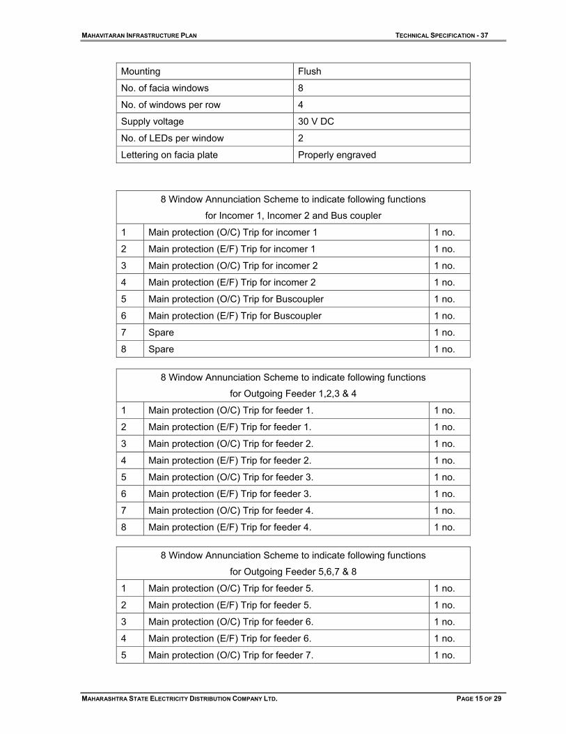
Mounting Flush
No. of facia windows 8
No. of windows per row 4
Supply voltage 30 V DC
No. of LEDs per window 2
Lettering on facia plate Properly engraved
8 Window Annunciation Scheme to indicate following functions
for Incomer 1, Incomer 2 and Bus coupler
1 Main protection (O/C) Trip for incomer 1 1 no.
2 Main protection (E/F) Trip for incomer 1 1 no.
3 Main protection (O/C) Trip for incomer 2 1 no.
4 Main protection (E/F) Trip for incomer 2 1 no.
5 Main protection (O/C) Trip for Buscoupler 1 no.
6 Main protection (E/F) Trip for Buscoupler 1 no.
7 Spare 1 no.
8 Spare 1 no.
8 Window Annunciation Scheme to indicate following functions
for Outgoing Feeder 1,2,3 & 4
1 Main protection (O/C) Trip for feeder 1. 1 no.
2 Main protection (E/F) Trip for feeder 1. 1 no.
3 Main protection (O/C) Trip for feeder 2. 1 no.
4 Main protection (E/F) Trip for feeder 2. 1 no.
5 Main protection (O/C) Trip for feeder 3. 1 no.
6 Main protection (E/F) Trip for feeder 3. 1 no.
7 Main protection (O/C) Trip for feeder 4. 1 no.
8 Main protection (E/F) Trip for feeder 4. 1 no.
8 Window Annunciation Scheme to indicate following functions
for Outgoing Feeder 5,6,7 & 8
1 Main protection (O/C) Trip for feeder 5. 1 no.
2 Main protection (E/F) Trip for feeder 5. 1 no.
3 Main protection (O/C) Trip for feeder 6. 1 no.
4 Main protection (E/F) Trip for feeder 6. 1 no.
5 Main protection (O/C) Trip for feeder 7. 1 no.

MAHAVITARAN INFRASTRUCTURE PLAN TECHNICAL SPECIFICATION - 37
MAHARASHTRA STATE ELECTRICITY DISTRIBUTION COMPANY LTD. PAGE 16 OF 29
6 Main protection (E/F) Trip for feeder 7. 1 no.
7 Main protection (O/C) Trip for feeder 8 1 no.
8 Main protection (E/F) Trip for feeder 8. 1 no.
5.8.3. The operators desk be made of sheet steel of thickness not less than 2 mm. and shall be free standing floor mounting indoor type. The desk should be dust moisture and vermin proof. It should be elegant in appearance and should be treated and painted as detailed in clause No.5.1.8.2.
5.8.4. The desk should be modular in construction. Each module should be about 800 mm. wide and should accommodate controls, indications and metering equipment for four feeder breakers and one module for the incomer & one B.C. The desk for the 11 panels switchgear Board (viz. 2 I/C + 1 B.C. + 8 O/G) shall have three such modules (Total length about 2.4 m). and the desk for the 7 panels switchgear Board ( viz. 2 I/C + 1 B.C. + 4 O/G) shall have two such modules (Total length about 1.6 m).
5.8.5. The two modules for 7 panel board and three modules for 11 panel Board should be assembled in such a way that the complete desk has a semi-circular/ arc-link configuration for easy and convenient operations.
6.0 TESTS: 6.1. TYPE TESTS: 6.1.1. The equipment offered in the tender should have been successfully type tested at NABL
laboratories for following tests in line with the relevant standard and technical specification, within the last 5 (five) years from the date of offer. The bidder shall be required to submit complete set of the type test reports alongwith the offer.
6.1.2. In case these type tests are conducted beyond five years, all the type tests as per the relevant standard shall be carried out by the successful bidder at NABL in presence of employer's representative free of cost before commencement of supply. The undertaking to this effect should be furnished along with the offer without which the offer shall be liable for rejection.
6.1.3. If above tests are carried out on higher capacity of offered equipment, then the offer is considered for placement of order. However, successful bidders have to carry out the said type tests on offered type equipment before commencement of supply at their own expense.
A. Switchgear Panel (with circuit breaker installed)
a. Lightning Impulse Voltage withstand Test
b. H.V. dry 1 min power frequency withstand test
c. Short time and peak withstand current test
d. Short circuit test with basic duties
e. Single phase breaking capacity test.
f. Temperature Rise test
B. Circuit Breaker
a. Mechanical Endurance Test
C. Current Transformer
a. Short Time Current Test
b. Impulse Voltage Withstand Test
MAHAVITARAN INFRASTRUCTURE PLAN TECHNICAL SPECIFICATION - 37
MAHARASHTRA STATE ELECTRICITY DISTRIBUTION COMPANY LTD. PAGE 17 OF 29
c. Temperature Rise Test
D. Potential Transformer
a. Impulse Voltage Withstand Test
b. Temperature Rise Test
E. Control & Relay Panel
a. IP Test
6.2. ACCEPTANCE AND ROUTINE TESTS: 6.2.1. All acceptance and routine tests as stipulated in relevant IS/IEC shall be carried out by
the supplier in the presence of employer's representative without any extra cost to the employer.
6.2.2. After finalisation of the program of type/acceptance/routine testing, the supplier shall give three weeks advance intimation to the employer, to enable him to depute his representatives for witnessing the tests.
7.0 INSPECTION: 7.1. The inspection may be carried out by the employer at any stage of manufacture. The
successful Tenderer shall grant free access to the employer's representative/s at a reasonable notice when the work is in progress. Inspection and acceptance of any equipment under this specification by the employer, shall not relieve the supplier of his obligation of furnishing equipment in accordance with the specification and shall not prevent subsequent rejection if the equipment is found to be defective.
7.2. The supplier shall keep the employer informed in advance, about the manufacturing program so that arrangement can be made for stage inspection.
7.3. The employer reserves the right to insist for witnessing the acceptance/routine testing of the bought out items. The supplier shall keep the employer informed, in advance, about such testing program.
8.0 QUALITY ASSURANCE PLAN: 8.1. The manufacturer shall invariably furnish following information & shall be separately
given for individual type and current rating of circuit breaker/ CTs/ PTs/ Panel mounting & accessories.
i. Statement giving information about names of sub-suppliers, list of testing standards, list of tests normally carried out for bought out item.
ii. Copies of test certificates in respect of following bought out items.
a. Vacuum Interrupter.
b. Insulators
c. Bus Bar Material
d. Instrument transformers.
e. Terminal connectors
iii. List of areas in manufacturing process, where stage inspection are normally carried out by the tenderer for quality control and details of such tests and inspections.
iv. List of testing equipment available with the manufacturer for final testing of breakers vis-a-vis the type, special, acceptance and routine tests specified
MAHAVITARAN INFRASTRUCTURE PLAN TECHNICAL SPECIFICATION - 37
MAHARASHTRA STATE ELECTRICITY DISTRIBUTION COMPANY LTD. PAGE 18 OF 29
herein. The limitations in testing facilities shall be very clearly brought out in Schedule-E i.e. schedule of deviation from specified test requirements.
8.2. The manufacturer shall submit the routine test certificates of bought out accessories at the time of routine testing of the fully assembled breaker for the goods manufactured within employer's country. The supplier shall also submit the central excise passes for the raw material at the time of routine testing of the fully assembled breaker.
9.0 PERFORMANCE GUARANTEE: Goods offered shall be guaranteed for a period of 60 months from the date of commissioning. The stores/materials found defective within the above guarantee period shall be replaced/ repaired by the supplier free of cost; within one month of receipt of intimation. If the defective stores/material are not replaced/repaired within the specified period as above, the board shall recover an equivalent amount plus 15% supervision charges from any of the bills of the suppliers.
10.0 DOCUMENTATION: 10.1. After receipt of letter of Award, the successful tenderers shall submit 3 sets of complete
drawings alongwith detailed bill of materials for approval. to the Chief Engineer, (Distribution/ Infra Plan) Department, Prakashgad, MSEDCL, Bandra (E). If any modifications are required on these, the same will be conveyed to the supplier who shall modify the drawings accordingly and furnish final drawings for approval. In no case delivery extension will be granted for any delay in drawing approval.
10.2. The manufacturing of the equipment shall be strictly in accordance with the approved
drawings and no deviation will be permitted without the written approval of the Distribution/ Infra Plan Department. All manufacturing and fabrication work in connection with the equipment prior to the approval of the drawings shall be at the suppliers risk.
10.3. After approval of the drawings and bills of materials, the suppliers shall submit detailed packing lists for approval. After approval, copies of these packing lists shall be forwarded to the respective consignees.
10.4. Six set of final drawings, bill of materials, wiring schedules, technical literature and commissioning manuals shall invariably be forwarded to the consignee alongwith the each panel consignment, and shall be listed out in the packing list when submitted for approval. All drawings shall preferably be of A3 size. No drawing of width more than 35 cm will be acceptable.
10.5. In case the supplier fails to furnish contractual drawings and manuals even at the time of supply of equipment, the date of furnishing of drawings/manuals will be considered as the date of supply of equipment for the purpose of computing penalties for late delivery.
10.6. List of drawings to be submitted :
i. GA of indoor 11 panel Switchgear.
ii. Typical single line diagram for 11 panel Switchgear.
iii. Sectional view of incomer, bus coupler & feeder panels.
iv. GA of Circuit Breaker truck.
v. GA of Current Transformer
vi. GA of Potential Transformer.
vii. G. A. Drawing for Control Desk.
MAHAVITARAN INFRASTRUCTURE PLAN TECHNICAL SPECIFICATION - 37
MAHARASHTRA STATE ELECTRICITY DISTRIBUTION COMPANY LTD. PAGE 19 OF 29
viii. Bill of material for complete switchgear.
ix. Technical particulars of Switchgears.
10.7. Successful tenderer shall furnish all above drawings and following additional drawings for approval before commencement of supply.
i. Foundation getails for 11 Panel Switchgear.
ii. Equipment door layout for incomer, bus coupler & feeder panels.
iii. Schematic Diagram for incomer bus coupler & feeder section of Switchgear
iv. Protection Circuit for incomer bus coupler & feeder section of Switchgear
v. DC control circuit for incomer, bus coupler & feeder section.
vi. Metering circuit for incomers, bus coupler & feeder section.
vii. Annunciator and Alarm scheme.
viii. P.T. supply change over scheme.
ix. Terminal block details for incomer, bus coupler & feeder section.
x. Cross section view for CTs.
xi. Name Plate & Connection diagram for CTs.
xii. Cross section view for PTs.
xiii. Name Plate & Connection diagram for PTs.
xiv. Schematic Diagram for Control Desk.
xv. G. A. Drawing for Chair.
xvi. G. A. Drawing for Sliding Door Unit.
11.0 PACKING AND FORWARDING : 11.1. The equipment shall be packed in crates suitable for vertical/horizontal transport as the
case may be and the packing shall be suitable to withstand handling during the transport and outdoor storage during transit. The supplier shall be responsible for any damage to the equipment during transit, due to improper and inadequate packing. The easily damageable materials shall be carefully packed and marked with the appropriate caution symbols. Wherever necessary, proper arrangement for lifting, such as lifting hooks etc. shall be provided. Any material found short inside the packing cases shall be supplied by the supplier without any extra cost.
11.2. Each consignment shall be accompanied by a detailed packing list containing the following information :
a. Name of the consignee
b. Details of consignment.
c. Destination
d. Total weight of consignment
e. Sign showing upper/lower side of the crate.
f. Handling and unpacking instructions.
g. Bill of material indicating contents of each package.
11.3. All the equipment covered in this specification shall be delivered to the various stores centers/ sites of the MSEDCL as will be intimated to the successful tenderers. The equipment shall be delivered to these stores centers/ sites only by road transport, and

MAHAVITARAN INFRASTRUCTURE PLAN TECHNICAL SPECIFICATION - 37
MAHARASHTRA STATE ELECTRICITY DISTRIBUTION COMPANY LTD. PAGE 20 OF 29
shall be suitably packed to avoid damages during transit in the case of indigenous supplies.
11.4. The tenderers shall quote delivery periods for various equipment, and shall stick-on to the committed delivery. The delivery period will be counted from the date of issue of detailed order. It may clearly be noted that the delivery periods will under no circumstances be linked up with other formalities like drawing approval, etc. It is therefore the responsibility of the successful tenders to submit the drawings, bill of materials, packing lists, etc. in time and get these approved by MSEDCL.
12.0 SCHEDULES The tenderer shall fill in the following schedules which is part and parcel of the tender specification and offer. If the schedules are not submitted duly filled in with the offer, the offer shall be liable for rejection.
Schedule 'A' ... Schedule of Deviation Schedule 'B' ... Tenderer's Experience Schedule 'C' ... Schedule of deviation from specified standards. Schedule 'D' ... Deviation from specified test requirements
All deviations from the specification shall be brought out in the schedules of deviation (Schedules 'A' 'C' & 'D"). Unless otherwise brought out specifically by the tenderer in the schedule of deviations (Schedule 'A', 'C' & 'D'), the items offered shall be deemed to conform to all clauses of the specification. The discrepancies if any between the specification and the categories or literature submitted as part of the offer by the bidder shall not be considered as valid deviations and no representations in this regard will be entertained unless these are specifically brought out in the schedule of deviations as stated above.
Any additional information other than those called for as per the above schedules may be furnished separately by the tenderer, if felt necessary by him.
13.0 INFORMATION TO BE FILLED IN & FURNISHED INVARIABLY BY THE TENDERERS:
13.1. The offers shall be complete in all respects, failing which the same are liable for rejection. In the bill of materials for each items, the tenderer shall state the type designation and make of each item/equipment. Unit prices of all items and sub-components shall be quoted. The list of items for which unit prices are quoted (without the price part) shall be submitted alongwith the technical offer. Guaranteed technical particulars for various equipment shall be elaborate and complete in all respects. It may be noted that the technical evaluation of the tender is made mainly based on the guaranteed technical particulars furnished alongwith the technical offer. Technical offer shall be submitted in duplicate, and each set shall include all the necessary particulars including the technical literature on various equipment.
14.0 FOLLOWING DOCUMENTS SHALL BE SUBMITTED: 14.1. Test certificates of Bus Bar for STC rating or undertaking in this respect.
14.2. Quality Assurance Plan.
14.3. Names of sub-suppliers.
14.4. List of testing equipment available with the manufacturer for final testing of breakers.

MAHAVITARAN INFRASTRUCTURE PLAN TECHNICAL SPECIFICATION - 37
MAHARASHTRA STATE ELECTRICITY DISTRIBUTION COMPANY LTD. PAGE 21 OF 29
14.5. Following Type Test Reports.
A. Switchgear Panel (with circuit breaker installed)
a. Lightning Impulse Voltage withstand Test
b. H.V. dry 1 min power frequency withstand test
c. Short time and peak withstand current test
d. Short circuit test with basic duties
e. Single phase breaking capacity test.
f. Temperature Rise test
B. Circuit Breaker
a. Mechanical Endurance Test
C. Current Transformer
a. Short Time Current Test
b. Impulse Voltage Withstand Test
c. Temperature Rise Test
D. Potential Transformer
a. Impulse Voltage Withstand Test
b. Temperature Rise Test
E. Control & Relay Panel
a. IP Test
14.6. Copies of test certificates in respect of following bought out items.
a. Vacuum Interrupter.
b. Insulators
c. Bus Bar Material
d. Instrument transformers.
e. Terminal connectors
MAHAVITARAN INFRASTRUCTURE PLAN TECHNICAL SPECIFICATION - 37
MAHARASHTRA STATE ELECTRICITY DISTRIBUTION COMPANY LTD. PAGE 22 OF 29
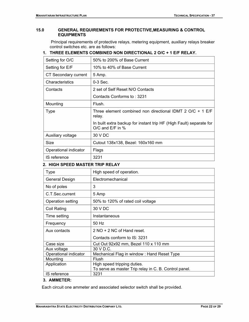
15.0 GENERAL REQUIREMENTS FOR PROTECTIVE,MEASURING & CONTROL EQUIPMENTS
Principal requirements of protective relays, metering equipment, auxiliary relays breaker control switches etc. are as follows:
1. THREE ELEMENTS COMBINED NON DIRECTIONAL 2 O/C + 1 E/F RELAY.
Setting for O/C 50% to 200% of Base Current
Setting for E/F 10% to 40% of Base Current
CT Secondary current 5 Amp.
Characteristics 0-3 Sec.
Contacts 2 set of Self Reset N/O Contacts
Contacts Conforms to : 3231
Mounting Flush.
Type Three element combined non directional IDMT 2 O/C + 1 E/F relay.
In built extra backup for instant trip HF (High Fault) separate for O/C and E/F in %
Auxiliary voltage 30 V DC
Size Cutout 138x138, Bezel: 160x160 mm
Operational indicator Flags
IS reference 3231
2. HIGH SPEED MASTER TRIP RELAY
Type High speed of operation.
General Design Electromechanical
No of poles 3
C.T.Sec.current 5 Amp
Operation setting 50% to 120% of rated coil voltage
Coil Rating 30 V DC
Time setting Instantaneous
Frequency 50 Hz
Aux contacts 2 NO + 2 NC of Hand reset.
Contacts conform to IS: 3231 Case size Cut Out 92x92 mm, Bezel 110 x 110 mm Aux voltage 30 V D.C. Operational indicator Mechanical Flag in window : Hand Reset Type Mounting Flush Application High speed tripping duties.
To serve as master Trip relay in C. B. Control panel. IS reference 3231
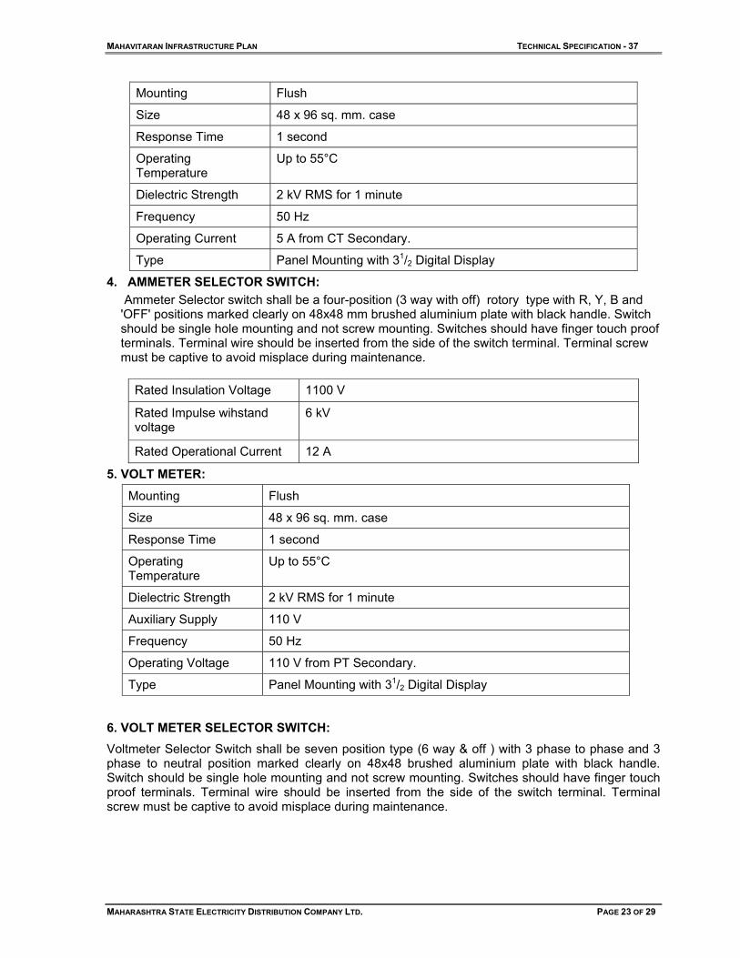
3. AMMETER: Each circuit one ammeter and associated selector switch shall be provided.
MAHAVITARAN INFRASTRUCTURE PLAN TECHNICAL SPECIFICATION - 37
MAHARASHTRA STATE ELECTRICITY DISTRIBUTION COMPANY LTD. PAGE 23 OF 29
Mounting Flush
Size 48 x 96 sq. mm. case
Response Time 1 second
Operating Temperature
Up to 55°C
Dielectric Strength 2 kV RMS for 1 minute
Frequency 50 Hz
Operating Current 5 A from CT Secondary.
Type Panel Mounting with 31/2 Digital Display
4. AMMETER SELECTOR SWITCH: Ammeter Selector switch shall be a four-position (3 way with off) rotory type with R, Y, B and 'OFF' positions marked clearly on 48x48 mm brushed aluminium plate with black handle. Switch should be single hole mounting and not screw mounting. Switches should have finger touch proof terminals. Terminal wire should be inserted from the side of the switch terminal. Terminal screw must be captive to avoid misplace during maintenance.
Rated Insulation Voltage 1100 V
Rated Impulse wihstand voltage
6 kV
Rated Operational Current 12 A
5. VOLT METER:
Mounting Flush
Size 48 x 96 sq. mm. case
Response Time 1 second
Operating Temperature
Up to 55°C
Dielectric Strength 2 kV RMS for 1 minute
Auxiliary Supply 110 V
Frequency 50 Hz
Operating Voltage 110 V from PT Secondary.
Type Panel Mounting with 31/2 Digital Display
6. VOLT METER SELECTOR SWITCH: Voltmeter Selector Switch shall be seven position type (6 way & off ) with 3 phase to phase and 3 phase to neutral position marked clearly on 48x48 brushed aluminium plate with black handle. Switch should be single hole mounting and not screw mounting. Switches should have finger touch proof terminals. Terminal wire should be inserted from the side of the switch terminal. Terminal screw must be captive to avoid misplace during maintenance.

MAHAVITARAN INFRASTRUCTURE PLAN TECHNICAL SPECIFICATION - 37
MAHARASHTRA STATE ELECTRICITY DISTRIBUTION COMPANY LTD. PAGE 24 OF 29
Rated Insulation Voltage 1100 V
Rated Impulse wihstand voltage
6 kV
Rated Operational Current 12 A
7. MULTIFUNCTION ELECTRICITY METER: 3 Phase 4 wire Static Tri-vector Meter having kWH element of class 0.5 accuracy with following parameters.
Class of accuracy 0.5
IS 13779
C.T. Ratio i) 400-200 /5A for feeder panels ii)800-400/5A for Incomer Panels
V.T. Ratio 11000/110V
Type Static
Mounting Flush
Measuring parameters kWh, kVArh, kVAh, instantaneous P.F., kW, kVA, supply frequency, phase voltages and phase currents.
Make Secure/L&T/L&G/Elster or equivalent
Display Customised backlit liquid crystal display
8. SPACE HEATER:
Capacity 80 Watts
Voltage 240 V AC
Type Strip type
9. THERMOSTAT:
Voltage 240 V AC
Range 30-90 Deg.C
10. CONTACTOR FOR ANTIPUMPING DUTY:
Contacts 2 N/O + N/C
Coil voltage 30V DC.
11. L/R. SWITCH: 4 way, 2 positions stay put handle
Contacts 2 contacts to close in each position
12. AUXILIARY CONTACTOR:
Contacts ARR 2 N/O+2 N/C
Auxiliary voltage 30 V DC
13. AUTO MANUAL SELECTOR SWITCH: Stay put type, pistol grip handle, 2 contacts to close in each position
Auxiliary voltage 30 V DC

MAHAVITARAN INFRASTRUCTURE PLAN TECHNICAL SPECIFICATION - 37
MAHARASHTRA STATE ELECTRICITY DISTRIBUTION COMPANY LTD. PAGE 25 OF 29
14. MICRO SWITCH:
Voltage 240 V AC
Contacts 1 N/C
15. D.C. SNAPER SWITCH WITH BLOW OUT MAGNET:
Type EX 110 of Elmex or equivalent
Current 5 Amps.
16. DISCREPANCY TYPE CONTROL SWITCH SUITABLE FOR REMOTE CONTROL OF CIRCUIT BREAKER:
Bulb voltage 30 V DC
17. DIGITAL FREQUENCY METER:
Mounting Flush in 96 sq.mm. case
Size 96 mm x 96 mm x 70 mm
Range 45 Hz to 55 Hz
Dielectric Strength 2 kV RMS for 1 minute
Power Consumption Less than 6 VA
Type Electronic 4 Digit Digital frequency meter.
Display Seven segment red colour LED Display with 0.5” hight
IS Referencee IS:1248
18. TERMINAL CONNECTOR:
Material Nickel plated Brass
Size of Stud Minimum 4 mm dia
Current capacity
a. Normal 10 amps
b. breaking 4 amps
Insulation 1100 V/3 kV of 1 min
Display Seven segment red colour LED Display with 0.5” hight
IS Referencee IS:1248

MAHAVITARAN INFRASTRUCTURE PLAN TECHNICAL SPECIFICATION - 37
MAHARASHTRA STATE ELECTRICITY DISTRIBUTION COMPANY LTD. PAGE 26 OF 29
SCHEDULE - A
SCHEDULE OF DEVIATIONS FROM SPECIFICATION
SR.NO. CLAUSE NO. DETAILS OF DEVIATION
NAME OF FIRM _______________________________________
NAME & SIGNATURE OF TENDERER_____________________
DESIGNATION _______________________________________
DATE _______________________________________________

MAHAVITARAN INFRASTRUCTURE PLAN TECHNICAL SPECIFICATION - 37
MAHARASHTRA STATE ELECTRICITY DISTRIBUTION COMPANY LTD. PAGE 27 OF 29
SCHEDULE – B
SCHEDULE OF TENDERER'S EXPERIENCE
Tenderer shall furnish here a list of similar orders executed/under execution by him to whom a reference may be made by employer in case he considers such a reference necessary.
Sr. No.
Name of Client & Description order
Value of order alongwith size & qty
Period of supply and commissioning
Name & Address to whom
reference may be made
1 2 3 4 5
NAME OF FIRM _______________________________________
NAME & SIGNATURE OF TENDERER_____________________
DESIGNATION _______________________________________
DATE _______________________________________________
MAHAVITARAN INFRASTRUCTURE PLAN TECHNICAL SPECIFICATION - 37
MAHARASHTRA STATE ELECTRICITY DISTRIBUTION COMPANY LTD. PAGE 28 OF 29
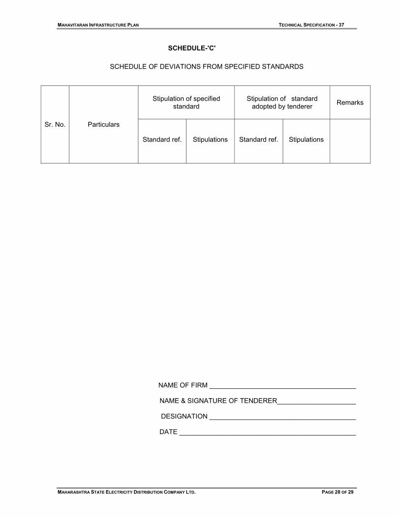
SCHEDULE-'C'
SCHEDULE OF DEVIATIONS FROM SPECIFIED STANDARDS
Stipulation of specified standard
Stipulation of standard adopted by tenderer Remarks
Sr. No. Particulars
Standard ref. Stipulations Standard ref. Stipulations
NAME OF FIRM _______________________________________
NAME & SIGNATURE OF TENDERER_____________________
DESIGNATION _______________________________________
DATE _______________________________________________

MAHAVITARAN INFRASTRUCTURE PLAN TECHNICAL SPECIFICATION - 37
MAHARASHTRA STATE ELECTRICITY DISTRIBUTION COMPANY LTD. PAGE 29 OF 29
SCHEDULE - D
DEVIATIONS FROM SPECIFIED TEST REQUIREMENTS SPECIFIED IN RELEVANT
AND PRESENT SPECIFICATIONS.
Sr. No. Name of Test Standard No.
& Clause No. Requirement of standards
Proposed deviation
Reasons for deviation.
1. TYPE TEST
2 ADDITIONAL TEST
3 ACCEPTANCE TEST
4 ROUTINE TEST
NAME OF FIRM _______________________________________
NAME & SIGNATURE OF TENDERER_____________________
DESIGNATION _______________________________________
DATE _______________________________________________