Embed Size (px)
Citation preview
PUB # 31-9117 04/04
MODEL SERIES:
MonogramInverter Compressor Side-By-Side
Refrigerators
GEA01265
GE Consumer & Industrial
TECHNICAL SERVICE GUIDE
ZIS360NRZIS420NRZIS480NRZIS_360DRZIS_420DRZIS_480DR

– 2 –
IMPORTANT SAFETY NOTICE
The information in this service guide is intended for use byindividuals possessing adequate backgrounds of electrical,electronic, and mechanical experience. Any attempt to repair amajor appliance may result in personal injury and propertydamage. The manufacturer or seller cannot be responsible for theinterpretation of this information, nor can it assume any liability inconnection with its use.
WARNING
To avoid personal injury, disconnect power before servicing thisproduct. If electrical power is required for diagnosis or testpurposes, disconnect the power immediately after performing thenecessary checks.
RECONNECT ALL GROUNDING DEVICES
If grounding wires, screws, straps, clips, nuts, or washers used tocomplete a path to ground are removed for service, they must bereturned to their original position and properly fastened.
GE Consumer & IndustrialTechnical Service Guide
Copyright © 2004All rights reserved. This service guide may not be reproduced in whole or in partin any form without written permission from the General Electric Company.
– 3 –
Table of Contents
Technical Data ........................................................................................................................ 5
Model Nomenclature .............................................................................................................. 6Rating Plate ...................................................................................................................... 6Mini-Manual ....................................................................................................................... 6Serial Number ................................................................................................................... 6
Component Locator Views ..................................................................................................... 7
Cabinet .................................................................................................................................. 10Machine Compartment ................................................................................................... 10Door Closure Mechanism.................................................................................................11Doors and Hinges .............................................................................................................11Door Gaskets .................................................................................................................... 12Rollers and Leveling ....................................................................................................... 12
Ice and Water Dispenser ...................................................................................................... 13Controls ............................................................................................................................ 13Water Valve and Water Tank ......................................................................................... 14
Airflow ................................................................................................................................... 15Damper ............................................................................................................................ 15
Fans ....................................................................................................................................... 16
Evaporator Fan ................................................................................................................ 16Condenser Fan ................................................................................................................ 20
Defrost System ...................................................................................................................... 21Adaptive Defrost .............................................................................................................. 21Normal Operating Characteristics .................................................................................. 21Defrost Heater .................................................................................................................. 22Evaporator Thermistor .................................................................................................... 23Defrost Overtemperature Thermodisc ........................................................................... 23
Control System ...................................................................................................................... 24Touch Panel and Temperature Control Board .............................................................. 24Thermistors ...................................................................................................................... 25Main Control Board ......................................................................................................... 26Main Control Board Locator Tables ............................................................................... 27Thermistors ...................................................................................................................... 32
Climate Control Drawer ........................................................................................................ 33Strip Circuit ...................................................................................................................... 33Component Locator View ............................................................................................... 34Operation ......................................................................................................................... 35Temperature Table .......................................................................................................... 36Climate Control Drawer Top Panel (Mullion) ................................................................ 37Control Board and Display ............................................................................................ 37Fan and Fan Housing ...................................................................................................... 39Dampers ........................................................................................................................... 40Heater ............................................................................................................................... 41Thermistor ........................................................................................................................ 41Air Flow ............................................................................................................................ 43

– 4 –
Table of Contents (cont.)
Compartment Lights ............................................................................................................. 44FF/FZ Compartment Lights Diagnostic .......................................................................... 44Door Switches ................................................................................................................. 45Master Light Switch ........................................................................................................ 45Temperature Overload Device (TOD) ............................................................................. 45Circuit Breakers ............................................................................................................... 46Transformers .................................................................................................................... 46Light Bulb Replacement ................................................................................................. 46
Schematics ............................................................................................................................ 49
Refrigeration System ............................................................................................................ 55Inverter Compressor ........................................................................................................ 55Inverter ............................................................................................................................. 57Accumulator .................................................................................................................... 59System Pressure .............................................................................................................. 59Refrigerant Charge ......................................................................................................... 59Drier.................................................................................................................................. 60Evaporator ....................................................................................................................... 60
Diagnostic Mode ................................................................................................................... 61
Compressor Not Running Flowchart .............................................................................. 62
Warranty ................................................................................................................................ 63
– 5 –
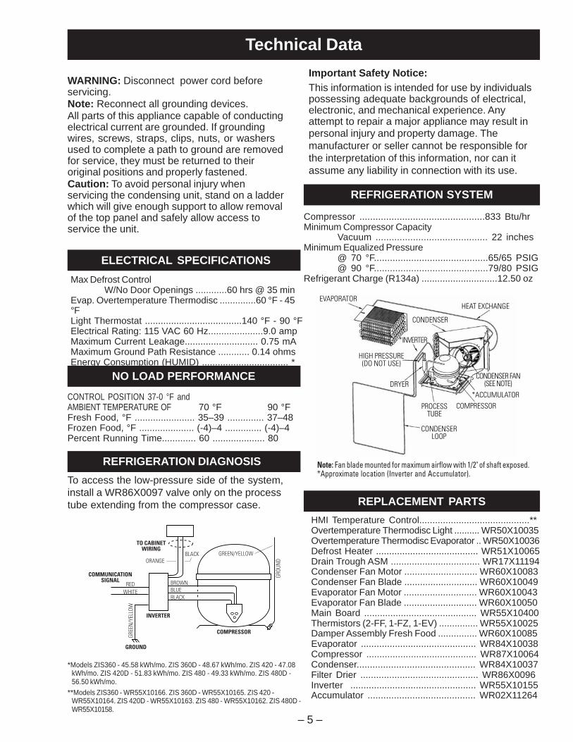
Technical DataImportant Safety Notice:This information is intended for use by individualspossessing adequate backgrounds of electrical,electronic, and mechanical experience. Anyattempt to repair a major appliance may result inpersonal injury and property damage. Themanufacturer or seller cannot be responsible forthe interpretation of this information, nor can itassume any liability in connection with its use.
Compressor ...............................................833 Btu/hrMinimum Compressor Capacity
Vacuum .......................................... 22 inchesMinimum Equalized Pressure
@ 70 °F...........................................65/65 PSIG@ 90 °F...........................................79/80 PSIG
Refrigerant Charge (R134a) .............................12.50 oz
HMI Temperature Control..........................................**Overtemperature Thermodisc Light .......... WR50X10035Overtemperature Thermodisc Evaporator .. WR50X10036Defrost Heater ....................................... WR51X10065Drain Trough ASM .................................. WR17X11194Condenser Fan Motor ............................ WR60X10083Condenser Fan Blade ............................ WR60X10049Evaporator Fan Motor ............................ WR60X10043Evaporator Fan Blade ............................ WR60X10050Main Board ........................................... WR55X10400Thermistors (2-FF, 1-FZ, 1-EV) ............... WR55X10025Damper Assembly Fresh Food ............... WR60X10085Evaporator ............................................ WR84X10038Compressor .......................................... WR87X10064Condenser............................................. WR84X10037Filter Drier ............................................. WR86X0096Inverter ................................................ WR55X10155Accumulator ......................................... WR02X11264
REPLACEMENT PARTS
TO CABINETWIRING
COMMUNICATIONSIGNAL
COMPRESSOR
GROUND
GREE
N/Y
ELLO
W
GROU
ND
RED
ORANGE
BLACK
BLACK GREEN/YELLOW
BLUEBROWN
WHITE
INVERTER
*Models ZIS360 - 45.58 kWh/mo. ZIS 360D - 48.67 kWh/mo. ZIS 420 - 47.08kWh/mo. ZIS 420D - 51.83 kWh/mo. ZIS 480 - 49.33 kWh/mo. ZIS 480D -56.50 kWh/mo.
**Models ZIS360 - WR55X10166. ZIS 360D - WR55X10165. ZIS 420 -WR55X10164. ZIS 420D - WR55X10163. ZIS 480 - WR55X10162. ZIS 480D -WR55X10158.
WARNING: Disconnect power cord beforeservicing.Note: Reconnect all grounding devices.All parts of this appliance capable of conductingelectrical current are grounded. If groundingwires, screws, straps, clips, nuts, or washersused to complete a path to ground are removedfor service, they must be returned to theiroriginal positions and properly fastened.Caution: To avoid personal injury whenservicing the condensing unit, stand on a ladderwhich will give enough support to allow removalof the top panel and safely allow access toservice the unit.
ELECTRICAL SPECIFICATIONS
NO LOAD PERFORMANCE
REFRIGERATION DIAGNOSIS
Max Defrost ControlW/No Door Openings ............60 hrs @ 35 min
Evap. Overtemperature Thermodisc ..............60 °F - 45°FLight Thermostat .....................................140 °F - 90 °FElectrical Rating: 115 VAC 60 Hz.....................9.0 ampMaximum Current Leakage............................ 0.75 mAMaximum Ground Path Resistance ............ 0.14 ohmsEnergy Consumption (HUMID) ................................. *
To access the low-pressure side of the system,install a WR86X0097 valve only on the processtube extending from the compressor case.
CONTROL POSITION 37-0 °F andAMBIENT TEMPERATURE OF 70 °F 90 °FFresh Food, °F ....................... 35–39 .............. 37–48Frozen Food, °F ..................... (-4)–4 .............. (-4)–4Percent Running Time............. 60 .................... 80
CONDENSERLOOP
PROCESSTUBE
COMPRESSOR*ACCUMULATOR
CONDENSER
HEAT EXCHANGEEVAPORATOR
HIGH PRESSURE(DO NOT USE)
*INVERTER
DRYERCONDENSER FAN
(SEE NOTE)
Note: Fan blade mounted for maximum airflow with 1/2" of shaft exposed.*Approximate location (Inverter and Accumulator).
REFRIGERATION SYSTEM
– 6 –
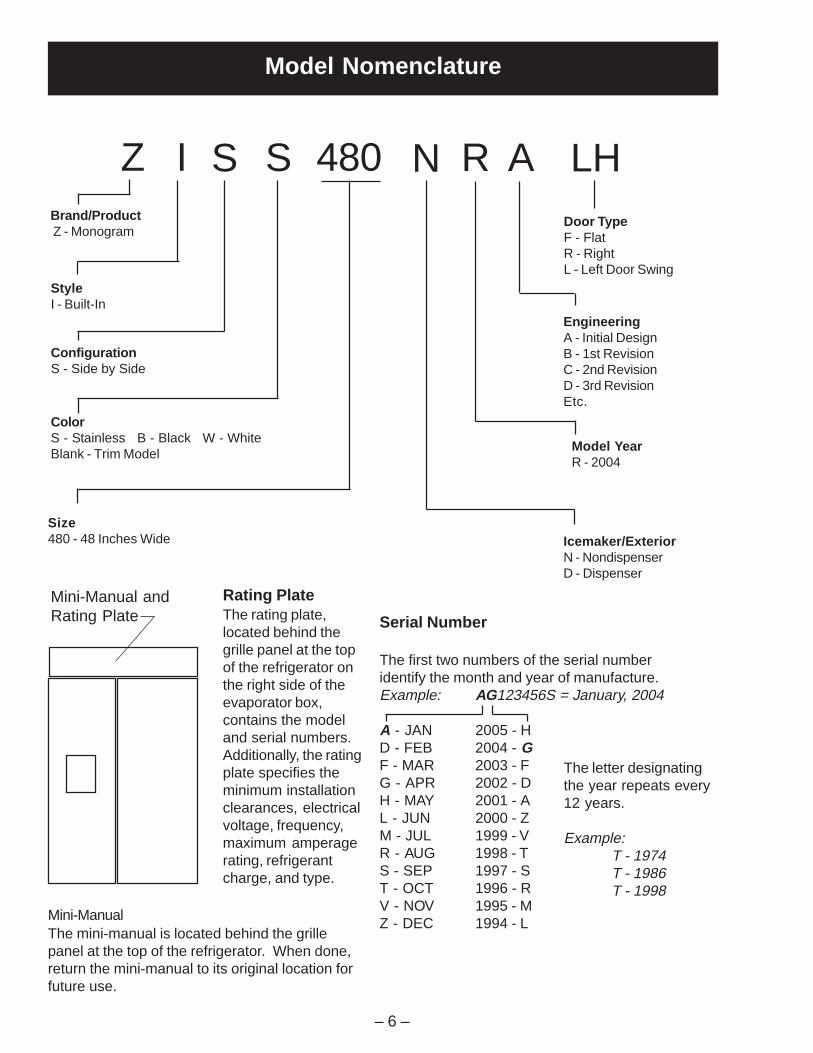
Model Nomenclature
Serial Number
The first two numbers of the serial numberidentify the month and year of manufacture.Example: AG123456S = January, 2004
A - JAN 2005 - HD - FEB 2004 - GF - MAR 2003 - FG - APR 2002 - DH - MAY 2001 - AL - JUN 2000 - ZM - JUL 1999 - VR - AUG 1998 - TS - SEP 1997 - ST - OCT 1996 - RV - NOV 1995 - MZ - DEC 1994 - L
The letter designatingthe year repeats every12 years.
Example:T - 1974T - 1986T - 1998
Rating PlateThe rating plate,located behind thegrille panel at the topof the refrigerator onthe right side of theevaporator box,contains the modeland serial numbers.Additionally, the ratingplate specifies theminimum installationclearances, electricalvoltage, frequency,maximum amperagerating, refrigerantcharge, and type.
Mini-ManualThe mini-manual is located behind the grillepanel at the top of the refrigerator. When done,return the mini-manual to its original location forfuture use.
Brand/Product Z - Monogram
StyleI - Built-In
ConfigurationS - Side by Side
ColorS - Stainless B - Black W - WhiteBlank - Trim Model
Size480 - 48 Inches Wide
EngineeringA - Initial DesignB - 1st RevisionC - 2nd RevisionD - 3rd RevisionEtc.
Door TypeF - FlatR - RightL - Left Door Swing
Icemaker/ExteriorN - NondispenserD - Dispenser
Model YearR - 2004
Z I S S 480 N R A LH
Mini-Manual andRating Plate
– 7 –
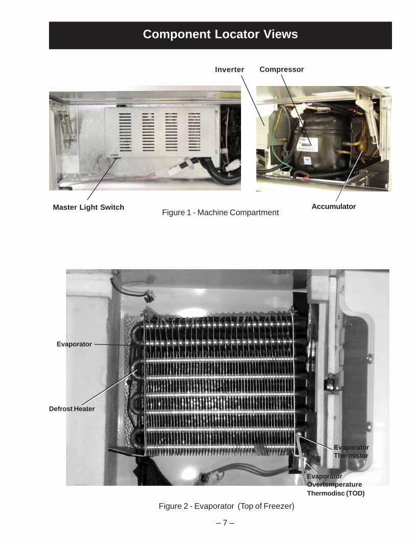
Component Locator Views
Figure 1 - Machine Compartment
Figure 2 - Evaporator (Top of Freezer)
Inverter Compressor
Master Light Switch
Evaporator
EvaporatorThermistor
EvaporatorOvertemperatureThermodisc (TOD)
Defrost Heater
Accumulator

– 8 –
Figure 3 - Water Valve(Center of Machine Compartment)
Figure 4 - Evaporator Fan
Figure 5 - Light Circuit Transformers
Water Valve
Evaporator Fan Motor
Evaporator FanConnector
Circuit Breakers
Housing UnderCenter of Unit
Transformers

– 9 –
Climate ControlDrawer Fan
Figure 6 - Freezer Compartment Figure 7 - Fresh Food Compartment
Freezer Door Switch
Auger Drive
Airflow Grille
Icemaker
Cube Solenoid
TemperatureOverload Device(TOD)
FreezerThermistor
Fresh FoodDoor Switch
Temperature Touch Pad
Damper
Water Filter
Fresh FoodThermistors
Climate ControlDrawer Dampers
TemperatureOverload Device(TOD)
LowerFresh FoodLights

– 10 –
Cabinet
The Master Light Switch is located behind thegrille panel.
Machine Compartment
2 Screws
The outer case is made of pre-painted galvanizedsteel. The fresh food and freezer liners arepainted metal with a smooth finish. The liners arenot removable or replaceable.
Machine Compartment
The machine compartment is located on the top ofthe unit and has a movable chassis that can beextended from the front of the unit to provideaccess to the refrigeration system components.
Caution: Avoid kinking the refrigeration lines whensliding the chassis out and back in.
To extend the chassis:
1. Remove the grille panel by removing 2 screwsfrom each side (see photo).
2. Remove the wire guard and rocker switchpanel.
3. Remove the condenser baffle.
4. Loosen the front 7/16-in. track bolts (1 on eachside of the compressor) from the front of thechassis track.
5. Remove the rear 7/16-in. track bolts (1 oneach side of the compressor) and the spacersunder the rear of the chassis track.
6. Pull the chassis forward until it reaches thestops in the tracks, working the refrigerationtubing as you pull the chassis out.
Note.
• When sliding the chassis back into position, becertain the lines and wiring have not fallenbehind the chassis.
• Use the grille screws for adjustment whenrealigning the grille.
Inverter
Chassis
Track Bolts

– 11 –
Doors and Hinges
The doors are of one-piece construction with foaminsulation.
The inner door panel and outer door panel cannotbe separated and must be replaced as anassembly.
Door Adjustment
Be sure the top hinge does not hit the cabinet trim.Adjust the door up or down by turning the threadedhinge pin on the bottom hinge of the fresh fooddoor.
The upper hinge on the freezer door is slotted toallow the freezer door to be adjusted left or right.
Door Removal
WARNING: Use the appropriate safety equipmentand lifting techniques. Two persons may berequired for door removal.
Caution: Use wood or a heavy plastic sheet toprotect the floor where the door will be placed.
1. Remove all food and bins from the inner doorliner and tape door to cabinet.
2. Disconnect the spring from the pin and theactuator arm.
3. Remove the Allen head bolt, bushing, andspacer from the door and actuator arm.
4. If removing the freezer door, shut off the watersupply, and disconnect the water line andelectrical connector.
5. Remove the upper hinge.
6. Lift door up and out to remove.
Door Closure Mechanism
The door closure mechanism uses a spring toprovide positive door closure from approximately60 degrees. The door closure mechanismactuator arm has a spring attached to the rear andis supported by guide rollers on either side of thebase channel. The roller circumferences and theactuator arm detents are matched for smoothoperation. The arm is attached to the door with anAllen head shoulder bolt.
The closure mechanism allows easy opening toapproximately 90 degrees, where the arm has adetent to permit the door to remain open at 90degrees with minimal tension. Once the door isopened beyond 90 degrees, the closuremechanism pulls the door open until the closurearm engages the door stop at approximately 130degrees (factory setting, the door stop can be fieldset to 90 degrees). The reverse action occurswhen the door is closed.
Note: The actuator arm is spring loaded withmoderate spring tension.
1. Disconnect the spring from the pin and theactuator arm.
2. Remove the 3/16-in. Allen head bolt, bushing,and spacer from the door and actuator arm.
3. Remove 2 screws and the roller assemblyfrom the rail. Replace roller if excessivelyworn.
GEA01267
DoorHinge
SpringPin
3/16"AllenHeadBolt
5/16"Bolt
ActuatorArm
RollerAssembly

– 12 –
Hex Nut
Wheel
Leveling Leg
Stripe(Handle Sideof Door)
Lower Door Hinge
Note: If replacing lower door hinge, note theplacement of the door stop (pin).
1. Remove the door.
Note: Note the placement of spacers and washers forreassembly.
2. Remove 3/8-in. hex screws (4) and hinge from theunderside of the cabinet.
3. Remove T-27 Torx screws (4) and hinge from thebottom of the door.
Rollers and Leveling
This model has 4-point leveling provided by adjustablerollers on the rear and leveling legs on the front. It alsohas 2 nonadjustable front rollers that are used only forunit positioning.
To level the unit:
1. Turn the 7/16-in. hex nut, located above the frontrollers, to adjust the roller on the rear of the unit.Turn clockwise to raise, counterclockwise to lower.
2. Turn the front legs with a 1-1/4 in. open endwrench to adjust the front of the unit. Turnclockwise to raise, counterclockwise to lower.
Door Gaskets
The fresh food and freezer doors have magneticgaskets that create a positive seal to the front of thesteel cabinet. The center mullion also has magnets toassist in door sealing. Improper installation of the doorgasket will cause same-poled magnets to oppose oneanother, preventing the door from closing tightly.
The magnetic door gaskets are secured to the doorsby a barbed edge that locks into a retainer channel.The side of the gasket that is nearest the handle of thedoor has a stripe on the inside of the barb (see photo).
Replacement
1. Starting at any corner, pull the old gasket out of theretaining channel.
2. Soak the new gasket in warm water to make itpliable.
3. Push the barbed edge of the gasket into theretainer channel.
GEA01268
Hinge
Door Stop
5/16"
Bolt
Hinge
BushingBase Channel Spacer
– 13 –
Ice and Water Dispenser
Screw
4 Screws
Duct DoorSolenoid
Light Socket Water Switch
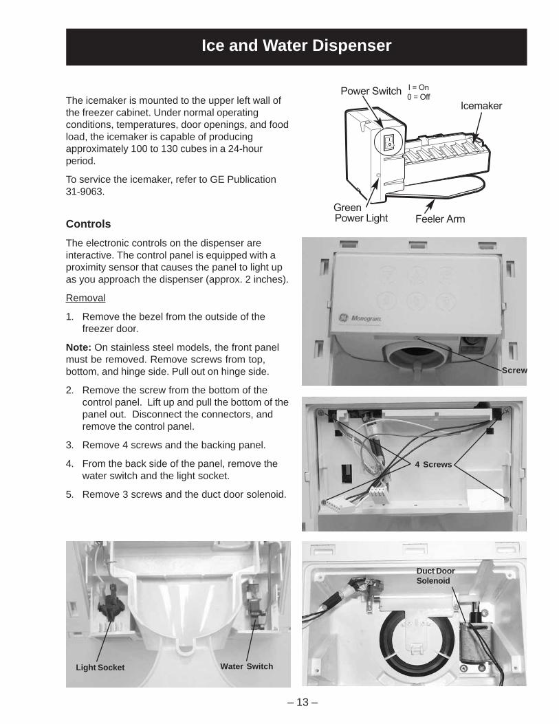
The icemaker is mounted to the upper left wall ofthe freezer cabinet. Under normal operatingconditions, temperatures, door openings, and foodload, the icemaker is capable of producingapproximately 100 to 130 cubes in a 24-hourperiod.
To service the icemaker, refer to GE Publication31-9063.
ControlsThe electronic controls on the dispenser areinteractive. The control panel is equipped with aproximity sensor that causes the panel to light upas you approach the dispenser (approx. 2 inches).
Removal
1. Remove the bezel from the outside of thefreezer door.
Note: On stainless steel models, the front panelmust be removed. Remove screws from top,bottom, and hinge side. Pull out on hinge side.
2. Remove the screw from the bottom of thecontrol panel. Lift up and pull the bottom of thepanel out. Disconnect the connectors, andremove the control panel.
3. Remove 4 screws and the backing panel.
4. From the back side of the panel, remove thewater switch and the light socket.
5. Remove 3 screws and the duct door solenoid.
Icemaker
Feeler Arm
Power Switch
GreenPower Light
I = On
0 = Off

– 14 –
To Replace the Water Valve
Note: Some water may leak from the water supplyline and valve when they are disconnected.
1. Shut off the water supply to the unit.
2. Open the grille panel.
3. Remove 1 Phillips screw attaching the watervalve to the filter bracket.
4. Disconnect the wiring harness connector and3 water lines from the water valve and remove.
To Replace the Chilled Water Tank
Note: Some water may leak from the water supplyline and valve when they are disconnected.
1. Shut off the water supply to the unit.
2. Remove 2 screws and the chilled water tankcover inside the fresh food compartment.
3. Remove 2 screws from the chilled water tank.
4. Cut the water lines leaving enough line toreconnect. Use union WR02X10471(5/16 x 5/16).
ScrewScrew
Chilled Water Tank
Water Tank Cover
Screws
Water Valve and Water Tank
The water valve is mounted in the left side of themachine compartment.
A plastic water line is routed from under the unit,up the back of the cabinet, into the machinecompartment, and to the water filter. A line thengoes from the water filter to the water valve.
Two low-pressure plastic water lines supply waterto the icemaker and door dispenser from the watervalve. A plastic water line is routed from the watervalve, out the back of the machine compartment,down the back of the cabinet through the bottom ofthe unit, and into the fresh food compartmentwhere it is attached to the cold water tank. A line isrouted from the cold water tank through the bottomof the unit into the freezer door to supply the waterdispenser. The icemaker water line is routed fromthe water valve through the machine compartmentto the icemaker. The icemaker fill tube is alsoplastic.
Note: No water filter should be installed if homehas in-home water filtration system (reverseosmosis filter system, etc.) Replace filter with by-pass plug.
Water Valve
– 15 –
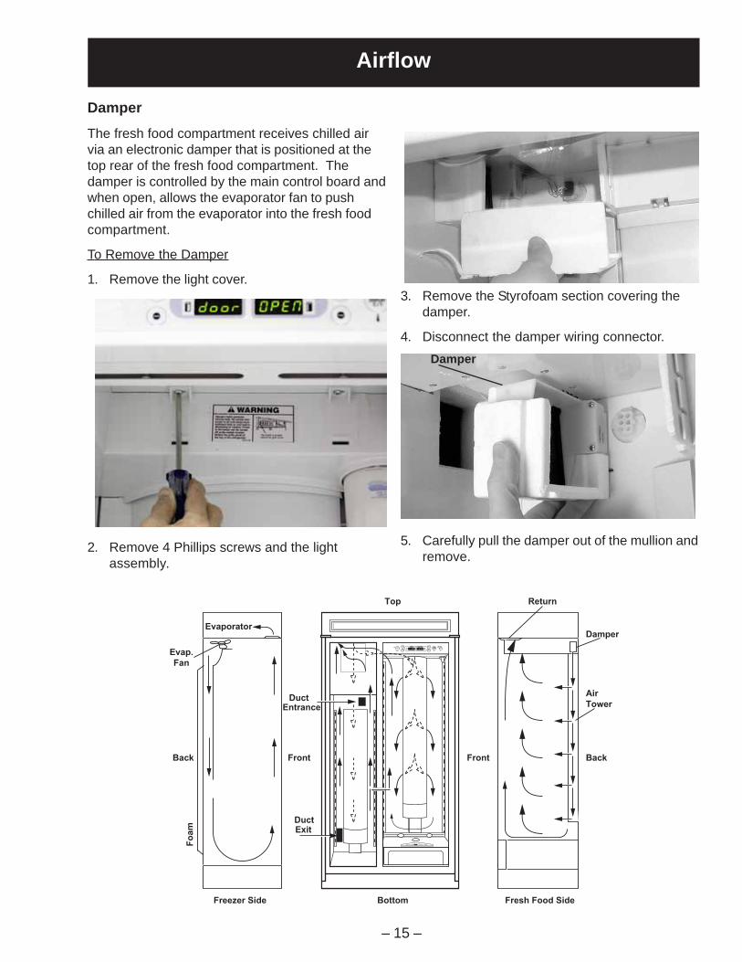
Airflow
2. Remove 4 Phillips screws and the lightassembly.
Damper
Damper
The fresh food compartment receives chilled airvia an electronic damper that is positioned at thetop rear of the fresh food compartment. Thedamper is controlled by the main control board andwhen open, allows the evaporator fan to pushchilled air from the evaporator into the fresh foodcompartment.
To Remove the Damper
1. Remove the light cover.3. Remove the Styrofoam section covering the
damper.
4. Disconnect the damper wiring connector.
5. Carefully pull the damper out of the mullion andremove.
Top
BottomFreezer Side Fresh Food Side
Return
Evaporator
Front FrontBack Back
Damper
Air
Tower
Evap.
Fan
Fo
am
DuctExit
DuctEntrance
– 16 –
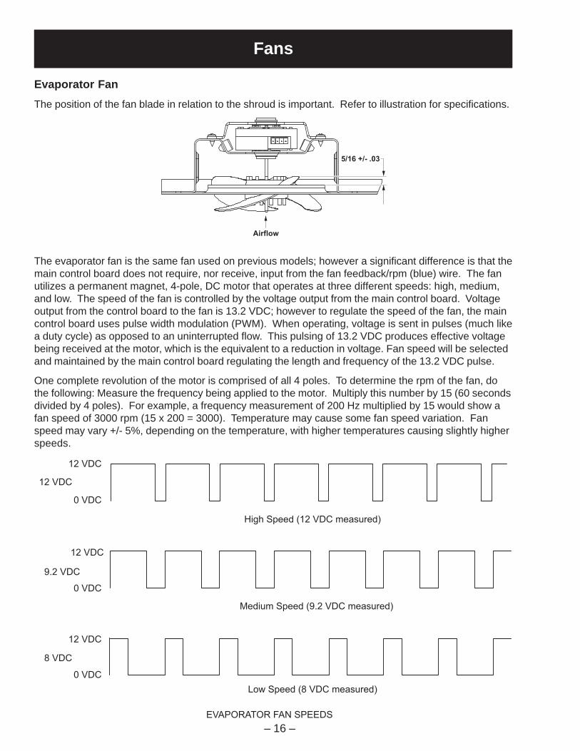
The evaporator fan is the same fan used on previous models; however a significant difference is that themain control board does not require, nor receive, input from the fan feedback/rpm (blue) wire. The fanutilizes a permanent magnet, 4-pole, DC motor that operates at three different speeds: high, medium,and low. The speed of the fan is controlled by the voltage output from the main control board. Voltageoutput from the control board to the fan is 13.2 VDC; however to regulate the speed of the fan, the maincontrol board uses pulse width modulation (PWM). When operating, voltage is sent in pulses (much likea duty cycle) as opposed to an uninterrupted flow. This pulsing of 13.2 VDC produces effective voltagebeing received at the motor, which is the equivalent to a reduction in voltage. Fan speed will be selectedand maintained by the main control board regulating the length and frequency of the 13.2 VDC pulse.
One complete revolution of the motor is comprised of all 4 poles. To determine the rpm of the fan, dothe following: Measure the frequency being applied to the motor. Multiply this number by 15 (60 secondsdivided by 4 poles). For example, a frequency measurement of 200 Hz multiplied by 15 would show afan speed of 3000 rpm (15 x 200 = 3000). Temperature may cause some fan speed variation. Fanspeed may vary +/- 5%, depending on the temperature, with higher temperatures causing slightly higherspeeds.
Fans
Evaporator FanThe position of the fan blade in relation to the shroud is important. Refer to illustration for specifications.
High Speed (12 VDC measured)
Medium Speed (9.2 VDC measured)
Low Speed (8 VDC measured)
EVAPORATOR FAN SPEEDS
12 VDC
9.2 VDC
8 VDC
12 VDC
0 VDC
0 VDC
0 VDC
12 VDC
12 VDC
5/16 +/- .03
Airflow

– 17 –
Evaporator and Condenser Fan Resistors
Evaporator Fan AdjustmentIf the fan shorts, it may damage the main controlboard. If the resistor on the main control board isburnt, you must replace the fan and the board (seephoto).
Evaporator Fan Resistor
Condenser Fan Resistor
J4 or J16 J3 or J10 J1 or J14
J2 OR J13
Some of the low voltage DC
connector labeling on this model
may differ from other models. The
function and diagnostics for these
connectors are identical for all
models.
5/16 +/- .03
Airflow
1 5 1 10 1 9
J1
or
J1
4
J5
6
J3
or
J1
0
J2
or
J1
3
1
DE
FR
OS
T
K4
21
J6
K5
CU
ST
OM
CO
OL
K7
PA
N
HE
AT
ER
CR
US
HE
R
K2
WA
TE
R
K3
J4
or
J1
6
18
J7 A
UG
ER
K1
1
J2
EA
RT
H
EA
RT
H
J1
J1
8
J1
2
J1
5
1
J1
9
J1
1
J9
Co
mm
. 2
-Wa
y D
igita
l
Co
mm
. +
12
V
Co
mm
. C
om
mo
n
Da
mp
er
- B
lue
Da
mp
er
- W
hite
Da
mp
er
- R
ed
Da
mp
er
- Y
ello
w
FF
1 T
he
rmis
tor
FF
2 T
he
rmis
tor
FZ
Th
erm
isto
r
Eva
po
rato
r T
he
rmis
tor
+5
V
Cu
sto
m C
oo
l D
am
pe
r1 +
Cu
sto
m C
oo
l D
am
pe
r1 -
+5
V
Cu
sto
m C
oo
l T
he
rmis
tor
Eva
po
rato
r F
an
Ta
ch
.
Fa
n C
om
mo
n
Eva
po
rato
r F
an
Co
nd
en
se
r F
an
Cu
sto
m C
oo
l F
an
Fa
n +
12
V
Inve
rte
r C
om
mo
nIn
ve
rte
r O
utp
ut
Dra
in P
an
He
ate
r
No
t U
se
d
De
fro
st H
ea
ter
Lin
e (
L1
)
Ne
utr
al
FZ
Do
or
Sw
itch
FF
Do
or
Sw
itch
Cu
sto
m C
oo
l H
ea
ter
Au
ge
r M
oto
r In
terlo
ck
Wa
ter
Va
lve
Cru
sh
er
So
len
oid
Au
ge
r M
oto
r
J8
No
t U
se
d

– 18 –
White Wire (DC Common)
The white wire is the DC common wire used fortesting. During repairs, DC polarity must beobserved. Reversing the DC polarity will cause ashorted motor and/or board.
Red Wire (Supply)
Each motor uses an internal electronic controllerto operate the motor. Supply voltage from themain control board remains at a constant12 VDC.
Blue Wire (Feedback/RPM)
The blue wire feeds rpm (speed) information tothe main control board, allowing the board tomaintain consistent fan speeds. Loss of feedbackfrom the blue wire will result in the fan acceleratingto maximum speed. Measure the fan rpm usingthe frequency between the blue and white wires.
High speed - 205 to 215 Hz (3140 RPM)Medium speed - 155 to 165 Hz (2415 RPM)Low speed - 140 to 150 Hz (2160 RPM)
Yellow Wire (Signal)
The yellow wire is the input wire from the maincontrol board. The main control board provides8 VDC effective voltage for low speed, 9.2 VDCeffective voltage for medium speed, and 12VDCfor high speed. The fan will operate in low speedonly when the fresh food thermistor is satisfied.
Note: When testing these motors:• You cannot test with an ohmmeter.• DC common is not AC common.• Verify 2 voltage potentials: a. Red to white - power for internal controller. b. Yellow to white - power for fan.• Observe circuit polarity.• Motors can be run for short periods using a 9-volt battery. Connect the white wire to the negative (-) battery terminal only. Connect the red and yellow wires to the positive (+) battery terminal.
J4 or J16 J3 or J10 J1 or J14
J2 OR J13
Some of the low voltage DC
connector labeling on this model
may differ from other models. The
function and diagnostics for these
connectors are identical for all
models.
1 5 1 10 1 9
J1
or
J1
4
J5
6
J3
or
J1
0
J2
or
J1
3
1
DE
FR
OS
T
K4
21
J6
K5
CU
ST
OM
CO
OL
K7
PA
N
HE
AT
ER
CR
US
HE
R
K2
WA
TE
R
K3
J4
or
J1
6
18
J7 A
UG
ER
K1
1
J2
EA
RT
H
EA
RT
H
J1
J1
8
J1
2
J1
5
1
J1
9
J1
1
J9
Co
mm
. 2
-Wa
y D
igita
l
Co
mm
. +
12
V
Co
mm
. C
om
mo
n
Da
mp
er
- B
lue
Da
mp
er
- W
hite
Da
mp
er
- R
ed
Da
mp
er
- Y
ello
w
FF
1 T
he
rmis
tor
FF
2 T
he
rmis
tor
FZ
Th
erm
isto
r
Eva
po
rato
r T
he
rmis
tor
+5
V
Cu
sto
m C
oo
l D
am
pe
r1 +
Cu
sto
m C
oo
l D
am
pe
r1 -
+5
V
Cu
sto
m C
oo
l T
he
rmis
tor
Eva
po
rato
r F
an
Ta
ch
.
Fa
n C
om
mo
n
Eva
po
rato
r F
an
Co
nd
en
se
r F
an
Cu
sto
m C
oo
l F
an
Fa
n +
12
V
Inve
rte
r C
om
mo
nIn
ve
rte
r O
utp
ut
Dra
in P
an
He
ate
r
No
t U
se
d
De
fro
st H
ea
ter
Lin
e (
L1
)
Ne
utr
al
FZ
Do
or
Sw
itch
FF
Do
or
Sw
itch
Cu
sto
m C
oo
l H
ea
ter
Au
ge
r M
oto
r In
terlo
ck
Wa
ter
Va
lve
Cru
sh
er
So
len
oid
Au
ge
r M
oto
r
J8
No
t U
se
d
– 19 –
Screws
Icemaker DriveMotor Assembly
Screws
ScrewsWiringCover
Screws
Evaporator Fan Cover
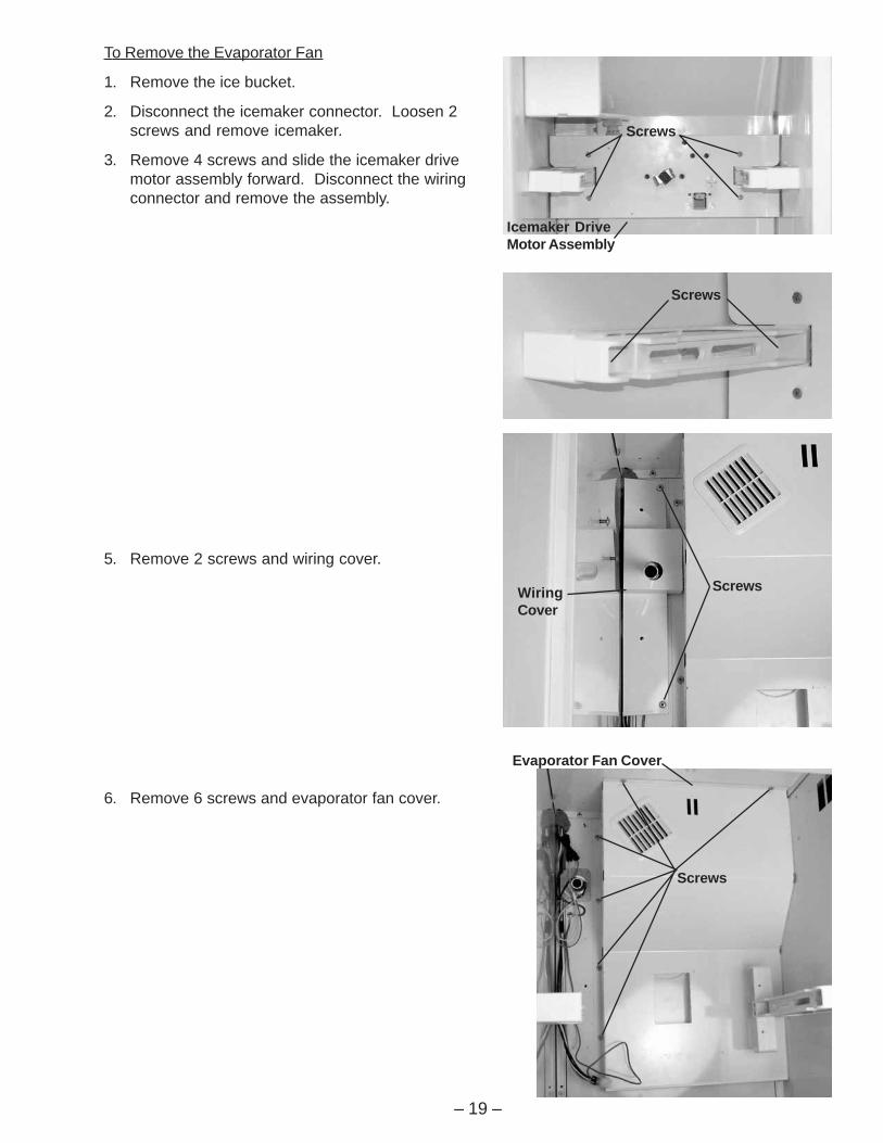
To Remove the Evaporator Fan
1. Remove the ice bucket.
2. Disconnect the icemaker connector. Loosen 2screws and remove icemaker.
3. Remove 4 screws and slide the icemaker drivemotor assembly forward. Disconnect the wiringconnector and remove the assembly.
5. Remove 2 screws and wiring cover.
6. Remove 6 screws and evaporator fan cover.

– 20 –
Condenser Fan Motor
Screws
Fan BracketFan Bracket
Screws
Wire Connector
Evaporator Fan
Condenser Fan
The condenser fan is a permanent-magnet, 4-pole, DC motor that will operate at 3 speeds. Fanspeed (low, medium, high) corresponds withcompressor speed to minimize pressurevariations in the sealed system. The speed of thefan is controlled by the voltage output from themain control board. Voltage output from thecontrol board to the fan is 13.2 VDC; however toregulate the speed of the fan, the main controlboard uses pulse width modulation (PWM). Whenoperating, voltage is sent in pulses (much like aduty cycle) as opposed to an uninterrupted flow.This pulsing of 13.2 VDC produces effectivevoltage being received at the motor, which is theequivalent to a reduction in voltage. Fan speed willbe selected and maintained by the main controlboard regulating the length and frequency of the13.2 VDC pulse. .
To Remove the Fan
1. Extend the chassis (see MachineCompartment in the Cabinet chapter).
2. Pull the blade off the motor shaft.
3. Cut the wire tie securing the fan wiring to thefan bracket.
Caution: Fan connector can be separated into 3segments (center, left side, and right side).Disconnect the fan connector at the center only.
4. Disconnect the fan connector.
5. Feed wiring through the hole in the fan shroud.
6. Remove 2 screws, top section of fan bracket,and motor.
7. Disconnect the evaporator fan wiringconnector.
8. Remove 2 screws from the fan mountingbracket and remove the fan.
– 21 –
Defrost System
Adaptive Defrost
Adaptive Defrost can be described as a defrostsystem that adapts to a refrigerator’s surroundingenvironment and household usage.
Unlike conventional defrost systems that useelectromechanical timers with a fixed defrost cycletime, Adaptive Defrost utilizes an intelligent,electronic control to determine when the defrostcycle is necessary. In order to accomplish thecorrect defrost cycle time, the main control boardmonitors the following refrigerator operations:
• Length of time the refrigerator doors were opensince the last defrost cycle
• Length of time the compressor has run sincethe last defrost cycle
• Amount of time the defrost heaters were on inthe last defrost cycle
Adaptive Defrost is divided into 4 separate cycles.Those operations are:
• Cooling Operation
• Pre-Chill Operation
• Defrost Heater Operation
• Dwell Period
(See Pub. #31-9062 for more information onAdaptive Defrost.)
Adaptive Defrost (Cooling Operation)
During the cooling operation, the main controlboard monitors door opening (fresh food door andfreezer drawer) and compressor run times. Theboard counts the time the doors are open. Itreduces the length of time between defrosts by300 seconds (multiplication factor) for eachsecond that each door is open (if both doors areopen, it reduces it by twice the amount). Themultiplication factor reduces compressor run time.If the doors are not opened, the compressor willrun up to 60 hours between defrosts. If the doorsare opened frequently and/or for long periods oftime, the compressor run time between defrostswill be reduced to as little as 8 hours.
Adaptive Defrost (Pre-Chill Operation)
When the main control board determines thatdefrost is necessary, it will force the refrigeratorinto a continuous cool mode (pre-chill). During pre-chill, the freezer temperature may be driven belowthe set point. However, the fresh food temperaturewill be regulated by the evaporator fan running atlow speed. Pre-chill will last for 30 minutes. Thesemodels do have an 8-hour defrost hold-off.
Adaptive Defrost (Defrost Heater Operation)
After 30 minutes of pre-chill operation, the maincontrol board turns off the compressor, condenserfan, and evaporator fan.
During defrost operation, the main control boardmonitors the evaporator temperature usingevaporator thermistor inputs. Typically, theevaporator thermistor will sense a temperature of45 °F within 16 minutes. When the thermistorsenses 45 °F, the main control board will terminatedefrost heater operation. Maximum defrost cycle(heater on) time is 35 minutes (main control boardtime out).
The defrost system is protected by a defrostovertemperature thermodisc (bimetal switch). Thethermostat opens when the evaporatortemperature raises to 60 °F and closes when theevaporator temperature lowers to 45 °F.
Adaptive Defrost (Dwell Period)
After defrost heater operation has been terminatedby the main control board, a 20-minute dwellperiod occurs. During this period, thecompressor, condenser fan, and evaporator fanremain off. The remaining frost melting from theevaporator will continue to drip and drain so that,prior to the cooling operation, the evaporator will betotally clear of any moisture. The pan heater is onfor the entire 20 minute dwell period.
Normal Operating Characteristics• The fill tube heater is on when the defrost
heaters are on.
• Pan heaters are on when the defrost heatersare on and during dwell period (25 minutesplus defrost time).
– 22 –
StyrofoamInsulation
Hose Clamp
Evaporator Drain Pan
ScrewsHeater
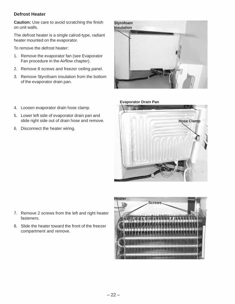
Defrost Heater
Caution: Use care to avoid scratching the finishon unit walls.
The defrost heater is a single calrod-type, radiantheater mounted on the evaporator.
To remove the defrost heater:
1. Remove the evaporator fan (see EvaporatorFan procedure in the Airflow chapter).
2. Remove 8 screws and freezer ceiling panel.
3. Remove Styrofoam insulation from the bottomof the evaporator drain pan.
4. Loosen evaporator drain hose clamp.
5. Lower left side of evaporator drain pan andslide right side out of drain hose and remove.
6. Disconnect the heater wiring.
7. Remove 2 screws from the left and right heaterfasteners.
8. Slide the heater toward the front of the freezercompartment and remove.
– 23 –
EvaporatorThermistor
DefrostOvertemperatureThermodisc
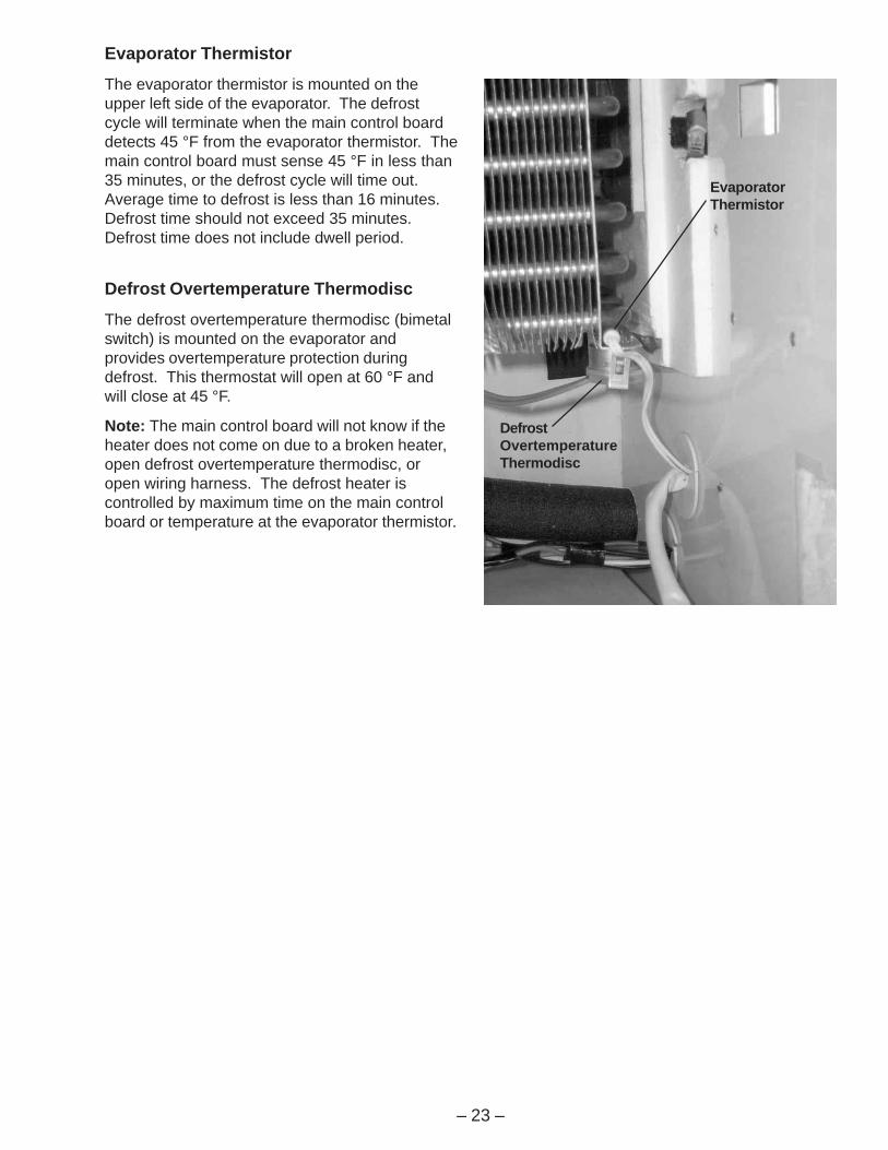
Evaporator Thermistor
The evaporator thermistor is mounted on theupper left side of the evaporator. The defrostcycle will terminate when the main control boarddetects 45 °F from the evaporator thermistor. Themain control board must sense 45 °F in less than35 minutes, or the defrost cycle will time out.Average time to defrost is less than 16 minutes.Defrost time should not exceed 35 minutes.Defrost time does not include dwell period.
Defrost Overtemperature Thermodisc
The defrost overtemperature thermodisc (bimetalswitch) is mounted on the evaporator andprovides overtemperature protection duringdefrost. This thermostat will open at 60 °F andwill close at 45 °F.
Note: The main control board will not know if theheater does not come on due to a broken heater,open defrost overtemperature thermodisc, oropen wiring harness. The defrost heater iscontrolled by maximum time on the main controlboard or temperature at the evaporator thermistor.

– 24 –
Control System
Touch Panel andTemperature Control BoardThe temperature control assembly is located atthe top front of the fresh food compartment andcontains the touch panel and temperature controlboard.
The temperature control board receives switchedDC voltage from the main control board. Inputconsists of pins 2 to 3. Failure of input results indefault to most recent setting. Pin 1 providesdigital communication between the temperaturecontrol board and the main control board. Failureof communication results in erratic control.
To remove the temperature control assembly:
1. Remove the light cover.
2. Remove 4 Phillips screws and the lightassembly.
Note: Temperature control assembly is mountedon 3 slotted fasteners. Fasteners do not need tobe loosened or removed.
3. Cut the RTV around the edge of thetemperature control assembly.
Note: Old RTV must be removed from the insideof the fresh food compartment and from thetemperature control assembly. RTV 102 must beput in place when the temperature control panel isinstalled.
4. Disconnect the temperature control assemblywiring connector.
5. Slide the temperature control assembly backto release it from the slotted fasteners andlower the assembly.
6. Disconnect the wiring connector from thetemperature control board.
7. Slide the touch panel out of the temperaturecontrol assembly.
8. Remove 2 screws and the temperature controlboard.
Temperature Control Assembly Touch Panel
Screws
Light Assembly
– 25 –
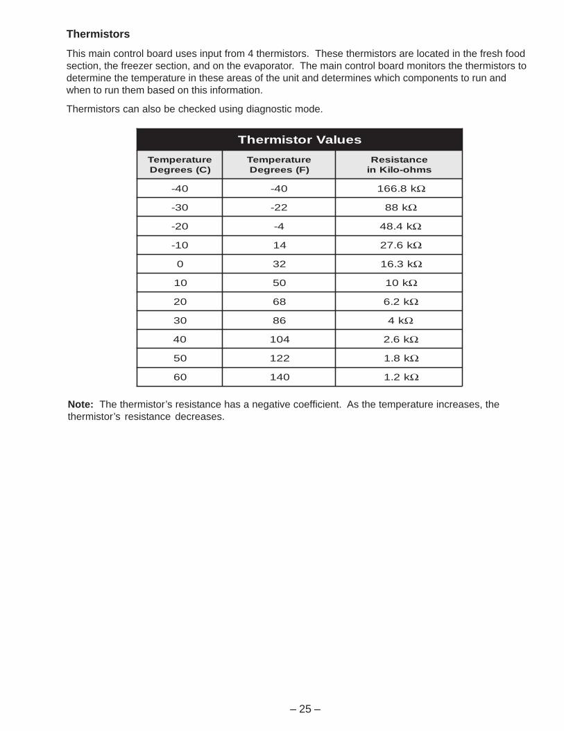
Note: The thermistor’s resistance has a negative coefficient. As the temperature increases, thethermistor’s resistance decreases.
seulaVrotsimrehTerutarepmeT)C(seergeD
erutarepmeT)F(seergeD
ecnatsiseRsmho-oliKni
04- 04- k8.661 Ω
03- 22- k88 Ω
02- 4- k4.84 Ω
01- 41 k6.72 Ω
0 23 k3.61 Ω
01 05 k01 Ω
02 86 k2.6 Ω
03 68 k4 Ω
04 401 k6.2 Ω
05 221 k8.1 Ω
06 041 k2.1 Ω
Thermistors
This main control board uses input from 4 thermistors. These thermistors are located in the fresh foodsection, the freezer section, and on the evaporator. The main control board monitors the thermistors todetermine the temperature in these areas of the unit and determines which components to run andwhen to run them based on this information.
Thermistors can also be checked using diagnostic mode.

– 26 –
Main Control Board
The main control board, located behind a metal cover at the top of the refrigerator in the machinecompartment, manages the operation of the refrigerator by calculating response from various inputs.
J4 o
r J16
J3 o
r J10
J1 o
r J14
J2 O
R J
13
So
me
of th
e lo
w v
olta
ge
DC
co
nn
ecto
r la
be
ling
on
th
is m
od
el
ma
y d
iffe
r fr
om
oth
er
mo
de
ls. T
he
fun
ctio
n a
nd
dia
gn
ostics fo
r th
ese
co
nn
ecto
rs a
re id
en
tica
l fo
r a
ll
mo
de
ls.
1 5 1 10 1 9
J1
or
J1
4
J5
6
J3
or
J1
0
J2
or
J1
3
1
DE
FR
OS
T
K4
21
J6
K5
CU
ST
OM
CO
OL
K7
PA
N
HE
AT
ER
CR
US
HE
R
K2
WA
TE
R
K3
J4 o
r J16
18
J7 A
UG
ER
K1
1
J2
EA
RT
H
EA
RT
H
J1
J1
8
J1
2
J1
5
1
J1
9
J1
1
J9
Com
m. 2-W
ay D
igital
Com
m. +
12V
Com
m. C
om
mon
Da
mp
er
- B
lue
Dam
per
- W
hite
Da
mp
er
- R
ed
Da
mp
er
- Y
ello
w
FF
1 T
herm
isto
r
FF
2 T
herm
isto
r
FZ
Therm
isto
r
Evapora
tor
Therm
isto
r
+5V
Cu
sto
m C
oo
l D
am
pe
r1 +
Custo
m C
ool D
am
per1
-
+5
V
Custo
m C
ool T
herm
isto
r
Eva
po
rato
r F
an
Ta
ch
.
Fa
n C
om
mo
n
Evapora
tor
Fan
Co
nd
en
se
r F
an
Custo
m C
ool F
an
Fa
n +
12
V
Invert
er
Com
mon
Invert
er
Outp
ut
Dra
in P
an
He
ate
r
No
t U
se
d
De
fro
st H
ea
ter
Lin
e (
L1
)
Neutr
al
FZ
Door
Sw
itch
FF
Door
Sw
itch
Custo
m C
ool H
eate
r
Auger
Moto
r In
terlock
Wate
r V
alv
e
Cru
sh
er
So
len
oid
Au
ge
r M
oto
r
J8
Not U
sed
– 27 –
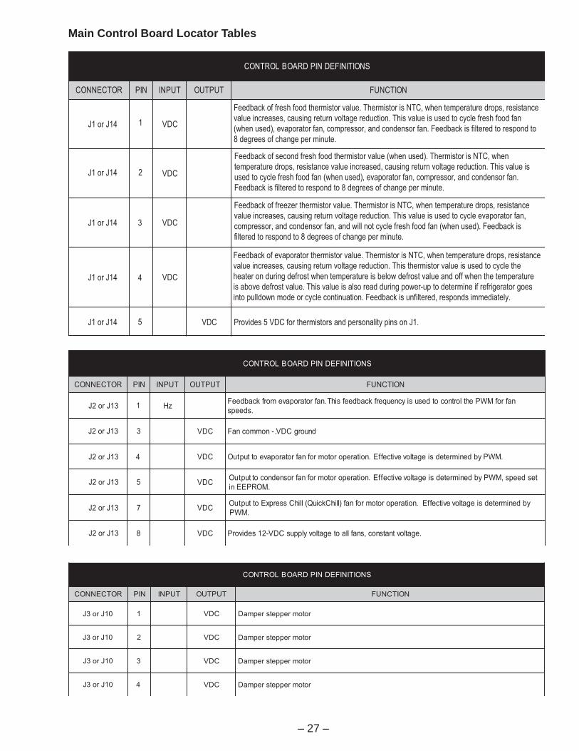
Main Control Board Locator Tables
SNOITINIFEDNIPDRAOBLORTNOC
ROTCENNOC NIP TUPNI TUPTUO NOITCNUF
J1 or J14 CDV
CDV
CDV
CDV
1
J1 or J14 2
J1 or J14 3
J1 or J14 4
5J1 or J14
Feedback of fresh food thermistor value. Thermistor is NTC, when temperature drops, resistance
value increases, causing return voltage reduction. This value is used to cycle fresh food fan
(when used), evaporator fan, compressor, and condensor fan. Feedback is filtered to respond to
8 degrees of change per minute.
Feedback of second fresh food thermistor value (when used). Thermistor is NTC, when
temperature drops, resistance value increased, causing return voltage reduction. This value is
used to cycle fresh food fan (when used), evaporator fan, compressor, and condensor fan.
Feedback is filtered to respond to 8 degrees of change per minute.
Feedback of freezer thermistor value. Thermistor is NTC, when temperature drops, resistance
value increases, causing return voltage reduction. This value is used to cycle evaporator fan,
compressor, and condensor fan, and will not cycle fresh food fan (when used). Feedback is
filtered to respond to 8 degrees of change per minute.
Feedback of evaporator thermistor value. Thermistor is NTC, when temperature drops, resistance
value increases, causing return voltage reduction. This thermistor value is used to cycle the
heater on during defrost when temperature is below defrost value and off when the temperature
is above defrost value. This value is also read during power-up to determine if refrigerator goes
into pulldown mode or cycle continuation. Feedback is unfiltered, responds immediately.
Provides 5 VDC for thermistors and personality pins on J1.VDC
SNOITINIFEDNIPDRAOBLORTNOC
ROTCENNOC NIP TUPNI TUPTUO NOITCNUF
zHnafrofMWPehtlortnocotdesusiycneuqerfkcabdeefsihT.nafrotaropavemorfkcabdeeF
.sdeeps
CDV . dnuorgCDV-nommocnaF
CDV .MWPybdenimretedsiegatlovevitceffE.noitareporotomrofnafrotaropaveottuptuO
CDVtesdeeps,MWPybdenimretedsiegatlovevitceffE.noitareporotomrofnafrosnednocottuptuO
.MORPEEni
CDVybdenimretedsiegatlovevitceffE.noitareporotomrofnaf)llihCkciuQ(llihCsserpxEottuptuO
.MWP
CDV . e.gatlovtnatsnoc,snafllaotegatlovylppusCDV-21sedivorP
J2 or J13 1
J2 or J13 3
J2 or J13 4
5J2 or J13
J2 or J13 7
8J2 or J13
SNOITINIFEDNIPDRAOBLORTNOC
ROTCENNOC NIP TUPNI TUPTUO NOITCNUF
CDV . rotomreppetsrepmaD
CDV . rotomreppetsrepmaD
CDV . rotomreppetsrepmaD
CDV . rotomreppetsrepmaD
J3 or J10
J3 or J10
J3 or J10
J3 or J10
1
2
4
3

– 28 –
J4 or J16 J3 or J10 J1 or J14
J2 OR J13
Some of the low voltage DC
connector labeling on this model
may differ from other models. The
function and diagnostics for these
connectors are identical for all
models.
SNOITINIFEDNIPDRAOBLORTNOC
ROTCENNOC NIP TUPNI TUPTUO NOITCNUF
latigiD
noitacinummoC
latigiD
noitacinummoC
lortnocerutarepmet,draoblortnocniamneewtebnoitacinummoclatigidyaw-owT
.draobllihCkciuQdna,draobresnepsid,)draob(
CDV . ylppusCDV-21
CDV .nommocCD
J4 or J16
J4 or J16
J4 or J16
1
2
3
SNOITINIFEDNIPDRAOBLORTNOC
ROTCENNOC NIP TUPNI TUPTUO NOITCNUF
5J 1 CDV.detcelessi)llihCkciuQ(llihCsserpxEnehwrepmadrewarDlortnoCetamilCotCDV21
.detcelessiwahtsserpxenehwdnuorgCDV-nommoC
5J 2 CDV.detcelessiwahTsserpxEnehwrepmadrewarDlortnoCetamilCotCDV21
.detcelessi)llihCkciuQ(llihCsserpxEnehwdnuorgCDV-nommoC
5J 5 CDV . rotsimreht)llihCkciuQ(llihCsserpxErofCDV5sedivorP
5J 6 CDV,sporderutarepmetnehw,CTNsirotsimrehT.rotsimreht)llihCkciuQ(llihCsserpxEfokcabdeeF
.egatlovnruterninoitcuderagnisuac,sesaercnieulavecnatsiser
SNOITINIFEDNIPDRAOBLORTNOC
ROTCENNOC NIP TUPNI TUPTUO NOITCNUF
7J 1 CAV . CAV021-rotomreguaehtotegatlov1LdehctiwS
7J 2 CAV . CAV021-dionelosrehsurcehtotegatlov1LdehctiwS
7J 3 CAV . CAV021-evlavretawehtotegatlov1LdehctiwS
7J 4 CAV .desolcsiroodrezeerfnehwhctiwsroodrezeerfmorftupni1LsevieceR
7J 5 CAV .CAV021-retaeh)llihCkciuQ(llihCsserpxEehtotegatlov1LdehctiwS
7J 6 CAV
desusitupnisihT.)neporood(sesolchctiwsnehwhctiwsrooddoofhserfmorftupni1LsevieceR
dna,snoitaluclacmralarood,snoitaluclacedomnoitcetorprenil,lortnocnafrotaropaverof
.snoitaluclactsorfedevitpada
7J 7 CAV
desusitupnisihT.)neporood(sesolchctiwsnehwhctiwsroodrezeerfmorftupni1LsevieceR
rood,snoitaluclactsorfedevitpada,snoitaluclacedomnoitcetorprenil,lortnocnafrotaropaverof
desolcroodnidesolcebtsumhctiwS.snoitcnufkcolretniroodemosdna,snoitaluclacmrala
.ezigreneottengamroodtcuddnathgilresnepsidrof)desserpedhctiws(noitisop
7J 9 CAV . nilartuenCA
– 29 –
J4 or J16 J3 or J10 J1 or J14
J2 OR J13
Some of the low voltage DC
connector labeling on this model
may differ from other models. The
function and diagnostics for these
connectors are identical for all
models.
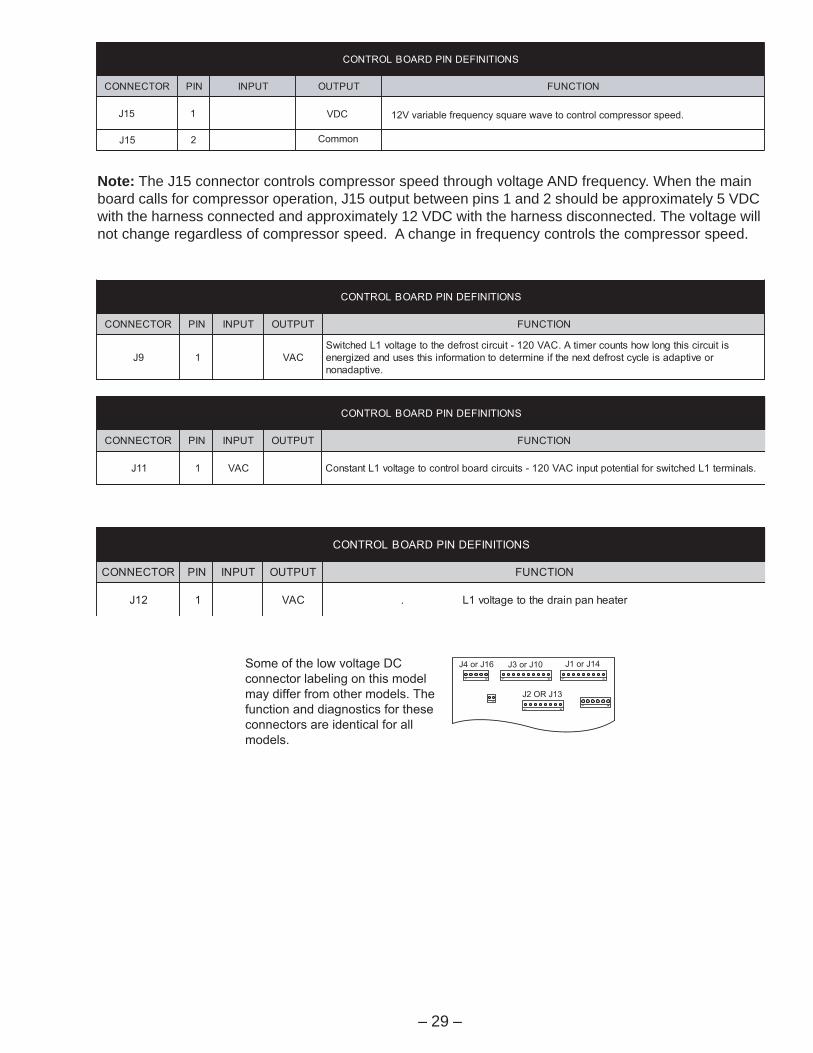
Note: The J15 connector controls compressor speed through voltage AND frequency. When the mainboard calls for compressor operation, J15 output between pins 1 and 2 should be approximately 5 VDCwith the harness connected and approximately 12 VDC with the harness disconnected. The voltage willnot change regardless of compressor speed. A change in frequency controls the compressor speed.
SNOITINIFEDNIPDRAOBLORTNOC
ROTCENNOC NIP TUPNI TUPTUO NOITCNUF
J15
J15
1
2
VDC
Common
12V variable frequency square wave to control compressor speed.
SNOITINIFEDNIPDRAOBLORTNOC
ROTCENNOC NIP TUPNI TUPTUO NOITCNUF
9J 1 CAV
sitiucricsihtgnolwohstnuocremitA.CAV021-tiucrictsorfedehtotegatlov1LdehctiwS
roevitpadasielcyctsorfedtxenehtfienimretedotnoitamrofnisihtsesudnadezigrene
.evitpadanon
SNOITINIFEDNIPDRAOBLORTNOC
ROTCENNOC NIP TUPNI TUPTUO NOITCNUF
11J 1 CAV .slanimret1LdehctiwsroflaitnetoptupniCAV021-stiucricdraoblortnocotegatlov1LtnatsnoC
SNOITINIFEDNIPDRAOBLORTNOC
ROTCENNOC NIP TUPNI TUPTUO NOITCNUF
21J 1 CAV . retaehnapniardehtotegatlov1L

– 30 –
J4 or J16 J3 or J10 J1 or J14
J2 OR J13
Some of the low voltage DC
connector labeling on this model
may differ from other models. The
function and diagnostics for these
connectors are identical for all
models.
11J,9J,8JdraoBlortnoCniaM
)ediSegatloV-hgiH(srotcennoC
niP roloCeriW tuptuO/tupnI gnidaeRegatloVniP-ot-niP
9J deR tuptu
O
AV021=9nip7Jot9J
11J nworB tupnI AV021=9nip7Jot11J
21J kcalB tuptu
O
AV021=9nip7Jot21J

– 31 –
1 5 1 10 1 9
J1
or
J1
4
J5
6
J3
or
J1
0
J2
or
J1
3
1
K2
J4 o
r J16
18
J2
EA
RT
H
J1
5
1
Cu
sto
m C
oo
l D
am
pe
r1 +
Cu
sto
m C
oo
l D
am
pe
r1 -
+5
V
Cu
sto
m C
oo
l T
he
rmis
tor
Eva
po
rato
r F
an
Ta
ch
.
Fa
n C
om
mo
n
Evapora
tor
Fan
Co
nd
en
se
r F
an
Cu
sto
m C
oo
l F
an
Fa
n +
12
V
Invert
er
Com
mon
Invert
er
Outp
ut
draoBlortnoCniaM)ediSCDegatloV-woL(rotcennoC3J
niP roloCeriW tnenopmoCnoitanimreT
/tupnItuptuO
gnidaeRegatloVniP-ot-niP
1 eulB rotoMreppetSrepmaD =3nip4Jot1nip3JCDV3.2egatloVgnidnatSCDV0.6=egatloVgnilevarT
2 etihW rotoMreppetSrepmaD =3nip4Jot2nip3JCDV3.2egatloVgnidnatSCDV0.6=egatloVgnilevarT
3 deR rotoMreppetSrepmaD =3nip4Jot3nip3JCDV3.2egatloVgnidnatSCDV0.6=egatloVgnilevarT
4 wolleY rotoMreppetSrepmaD =3nip4Jot4nip3JCDV3.2egatloVgnidnatSCDV0.6=egatloVgnilevarT
draoBlortnoCniaM)ediSCDegatloV-woL(rotcennoC2J
niP roloCeriW tnenopmoCnoitanimreT
/tupnItuptuO
gnidaeRegatloVniP-ot-niP
1 eulB nafrotaropavEretemohcat
tupnI CDV3.6=3nipot1nip2J
3 etihW nommocnaF nommoC CDV21=8nipot3nip2J
4 wolleY nafrotaropavE tuptuO CDV6.21=3nipot4nip2J,).dem(CDV1.8,)hgih(
)wol(CDV1.8
5 kniP nafresnednoC tuptuO CDV4.31=3nipot5nip2Jelgnissinafresnednoc(
)deeps
6 kcalB nafnapniarD dnuorG dnuorgCDV
7 kcalB nafllihCkciuQ nommoC CDV21=7nipot8nip2J
8 deR egatlovylppusnaF)CDV21(
tuptuO CDV21=3nipot8nip2J
draoBlortnoCniaM)ediSCDegatloV-woL(rotcennoC1J
niP roloCeriW tnenopmoCnoitanimreT
/tupnItuptuO
gnidaeRegatloVniP-ot-niP
1 elpruP doofhserF1rotsimreht
tupnI 5.3ot8.2=5nipot1nip1JCDV
2 eulB doofhserF2rotsimreht
tupnI 5.3ot8.2=5nipot2nip1JCDV
3 deR rotsimrehtrezeerF tupnI 5.3ot8.2=5nipot3nip1JCDV
4 kcalB rotaropavErotsimreht
tupnI 5.3ot8.2=5nipot4nip1JCDV
5 nworB ylppusrotsimrehT)CDV5(egatlov
tuptuO CDV5=3nip4Jot5nip1J
draoBlortnoCniaM)ediSCDegatloV-woL(rotcennoC5J
niP eriWroloC
tnenopmoCnoitanimreT
/tupnItuptuO gnidaeRegatloVniP-ot-niP
1 wolleYllihCkciuQ
)looCmotsuC(repmaD
/tupnItuptuO )ytiralopgnisrever(CDV21=2nipot1nip5J
2 yarGllihCkciuQ
)looCmotsuC(repmaD
/tupnItuptuO )ytiralopgnisrever(CDV21=1nipot2nip5J
5 nworB egatloVylppuS)CDV5( tuptuO CDV5=3nip2Jot01nip5J
6 eulBllihCkciuQ
)looCmotsuC(rotsimrehT
tupnI A/N
draoBlortnoCniaM)ediSCDegatloV-woL(rotcennoC4J
niP roloCeriW tnenopmoCnoitanimreT
tuptuO/tupnI gnidaeRegatloVniP-ot-niP
1 deR erutarepmeTlortnoc
noitacinummoC noitacinummoclatigidyaw-owT,draoblortnocniamneewteb,)draob(lortnocerutarepmet
dna,draobresnepsid.draobllihCkciuQ
2 nworB erutarepmeTlortnoc
CDV .ylppusCDV-21
3 egnarO erutarepmeTlortnoc
CDV .nommocCD
Some of the low voltage DC
connector labeling on this model
may differ from other models. The
function and diagnostics for these
connectors are identical for all
models.
J4 or J16 J3 or J10 J1 or J14
J2 OR J13

– 32 –
Thermistors
This main control board uses input from 4 thermistors. These thermistors are located in the fresh foodsection, the freezer section, and on the evaporator. The main control board monitors the thermistors todetermine the temperature in these areas of the unit and determines which components to run andwhen to run them based on this information.
seulaVrotsimrehTerutarepmeT)C(seergeD
erutarepmeT)F(seergeD
ecnatsiseRsmho-oliKni
04- 04- k8.661 Ω
03- 22- k88 Ω
02- 4- k4.84 Ω
01- 41 k6.72 Ω
0 23 k3.61 Ω
01 05 k01 Ω
02 86 k2.6 Ω
03 68 k4 Ω
04 401 k6.2 Ω
05 221 k8.1 Ω
06 041 k2.1 Ω
trahCtnioPteSerutarepmeT
dooFhserFlortnoC
gnitteS
dooFhserFrotsimrehT
egnaRerutarepmeT
rezeerFlortnoC
gnitteS
rotsimrehTrezeerFegnaRerutarepmeT
muminiM mumixaM muminiM mumixaM
F°43 F°23 F°63 F°5- F°01- F°0
F°53 F°33 F°73 F°4- F°9- F°1
F°63 F°43 F°83 F°3- F°8- F°2
F°73 F°53 F°93 F°2- F°7- F°3
F°83 F°63 F°04 F°1- F°6- F°4
F°93 F°73 F°14 F°0 F°5- F°5
F°04 F°83 F°24 F°1 F°4- F°6
F°14 F°93 F°34 F°2 F°3- F°7
F°24 F°04 F°44 F°3 F°2- F°8
F°34 F°14 F°54 F°4 F°1- F°9
F°44 F°24 F°64 F°5 F°0 F°01
F°54 F°34 F°74 F°6 F°1 F°11

– 33 –
Climate Control Drawer
The Climate Control Drawer compartment is sealed to reduce the effect that the drawer temperaturehas on the rest of the refrigerator. When the drawer features are not being used, the temperature insidethe drawer will be the same as the fresh food compartment.
Strip Circuit
The Climate Control Drawer can chill or thaw itemsquickly. It can also store items at their optimumtemperatures. This Climate Control Drawercontains the following components:• Control Board• Thermistor• Dampers (2)• Fan• Heater
The main control board controls the dampers, fan,and heater based on input from the Climate ControlDrawer’s control board and the thermistor.
J4 or J16 J3 or J10 J1 or J14
J2 OR J13
Some of the low voltage DC
connector labeling on this model
may differ from other models. The
function and diagnostics for these
connectors are identical for all
models.
DAMPER
THERMISTORBLUE
J7
HEATER 5 VIOLET ORANGE
OR
AN
GE
OR
AN
GE
GR
EE
N
AC POWER CORD
BR
OW
NB
RO
WN
EMI/RFFILTER
HEATER
1 DATA
3 COM
J4
J5
6
5
2
1
J2
8 +12 VDC
MAIN CONTROL
BOARD
7 FAN
BROWN
RED
ORANGE
BROWN
RED
ORANGE
BROWN
WHITE
YELLOW
GRAY
YELLOW
WHITE RED
BLACK
1
1
3CONTROL
BOARD(CONTROL HMI)
5
2
DAMPER
FAN
WHITE
YELLOW
1
2
GEA01264
2 + 12 VDC
441 Ohms
– 34 –
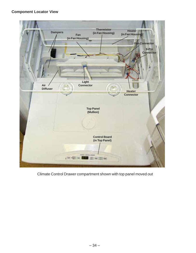
Climate Control Drawer compartment shown with top panel moved out
Component Locator View
Fan(in Fan Housing)
Thermistor(in Fan Housing)
AirDiffuser
Dampers Heater(in Fan Housing)
Top Panel(Mullion)
Control Board(in Top Panel)
HeaterConnector
9-PinConnector
Fan Connector
LightConnector

– 35 –
Operation
During all modes of operation, the main control board will cycle the dampers, fan, and heater asnecessary to maintain the desired temperature. Typical operation is as follows:
Select Temp
This feature maintains optimum temperatures for specific items.
The CITRUS setting will maintain a drawer temperature of 43 °F by circulating warmed air or cooledair as needed. The dampers will close and the heater will turn on if warmed air is required to maintain43 °F. The dampers will open if cooled air is required.
The PRODUCE setting will maintain a drawer temperature of 35 °F by circulating warmed air or cooledair as needed. The dampers will close and the heater will turn on if warmed air is required to maintain34 °F. The dampers will open if cooled air is required.
The MEAT setting will maintain a drawer temperature of 32 °F by circulating warmed air or cooledair as needed. The dampers will close and the heater will turn on if warmed air is required to maintain32 °F. The dampers will open if cooled air is required.
The Climate Control drawer display will show the selected temperature for approximately 4 secondsafter a Select Temp mode has been selected. After approximately 4 seconds, the actual temperature ofthe drawer will be displayed. Refer to the Temperature Table for drawer temperatures.
Express Chill
This feature cools items by opening the dampers and circulating air from the freezer compartmentthroughout the drawer. The fan will be on at all times during Express Chill.
The Climate Control Drawer display will show the number of minutes (or minutes remaining) for theExpress Chill mode selected on the control panel. The display will not show the temperature of thedrawer. Refer to the Temperature Table for drawer temperatures.
Express Thaw
This feature thaws items by circulating warmed air throughout the drawer. Temperature is maintained inthe drawer by cycling a small heater on and off as needed. The dampers will be closed during ExpressThaw. The fan will be on at all times during Express Thaw.
When the Express Thaw cycle is complete, the drawer will automatically adjust to 30 °F.
The Climate Control Drawer display will show the number of hours (or hours remaining) for the ExpressThaw mode selected on the control panel (.5 LBS = 4 HRS, 1.5 LBS = 8 HRS, 3 LBS = 12 HRS). Thedisplay will not show the temperature of the drawer. Refer to the Temperature Table for drawertemperatures.

– 36 –
Temperature Table
When using the Temperature Table, please note the following:
• FF and FZ compartments should be within 3 °F of the temperature set point when checking drawertemperature.
• All temperatures listed are as measured by the thermistor and displayed by the Climate ControlDrawer display.
• Actual drawer temperature will be displayed in Select Temp mode only. The Climate Control Drawerdisplay will show the selected temperature for approximately 4 seconds after a Select Temp modehas been selected. After approximately 4 seconds, the actual temperature of the drawer will bedisplayed.
• The actual-temperature display is based on the temperature that the main control board sees fromthe thermistor. The selected-temperature (example: CITRUS – 43 °F) is based on the logic of theClimate Control Drawer control board. If the actual temperature that is displayed is incorrect, thethermistor and main control board are suspect. If the temperature associated with the Select Tempmode is incorrect, the Climate Control Drawer control board is faulty.
Note 1 Climate Control Drawer may take up to 1 hour and 45 minutes to achieve temperature with noload in drawer (except metal tray) and minimal or no door openings. When the Express Thaw cycle iscomplete, the drawer will automatically adjust to 30 °F.
Note 2 Temperature should lower to 25 °F or less within 15 minutes with no load in drawer (exceptmetal tray) and minimal or no door openings. Temperature should lower to a temperature between 15°F to 20 °F within 30 minutes with no load in drawer (except metal tray) and minimal or no dooropenings. If refrigerator is defrosting, temperature in drawer may go below 15 °F.
Note 3 Climate Control Drawer may take up to 1 hour and 45 minutes to achieve temperature with noload in drawer (except metal tray) and minimal or no door openings.
Note 4 Climate Control Drawer may take up to 1 hour to achieve temperature with no load in drawer(except metal tray) and minimal or no door openings.
Note 5 Climate Control Drawer may take up to 45 minutes to achieve temperature with no load indrawer (except metal tray) and minimal or no door openings.
WAHTSSERPXE LLIHCSSERPXE PMETTCELES
EDOM PMET EDOM PMET EDOM PMET
.SBL5. F˚64ot24 1 .NIM51 F˚52 2 SURTIC F˚34 3
.SBL5.1 F˚64ot24 1 .NIM03 F˚02ot51 2 ECUDORP F˚53 4
.SBL3 F˚64ot24 1 .NIM54 F˚02ot51 2 TAEM F˚23 5

– 37 –
Climate Control Drawer Top Panel(Mullion)Removal
1. Remove 2 storage bins and the glass panelover Climate Control Drawer.
2. Remove 4 screws from climate control topand slide back to access wire connectors.
3. Disconnect the connectors and remove thetop panel.
Note: Note that there is a Styrofoam insert in theslot at the back, right-hand corner of the toppanel.
Screws
Styrofoam Insert
Top Panel(Mullion)
Control Board and Display
The control board and display are located in theClimate Control Drawer top panel (mullion). Thecontrol board and display are part of the mullionand cannot be replaced separately.
Input from the Climate Control Drawer’s controlboard and the thermistor is used by the maincontrol board to control the dampers, fan, andheater.
Actual drawer temperature will be displayed inSelect Temp mode only. The Climate ControlDrawer display will show the selected temperaturefor approximately 4 seconds after a Select Tempmode has been selected. After approximately 4seconds, the actual temperature of the drawer willbe displayed.
The actual-temperature display is based on thetemperature that the main control board sees fromthe thermistor. The selected temperature(example: CITRUS – 45 °F, is based on the logic ofthe Climate Control Drawer control board. If theactual temperature that is displayed is incorrect,the thermistor and main control board are suspect.If the temperature associated with the Select Tempmode is incorrect, the Climate Control Drawercontrol board is faulty.
.

– 38 –
Caution: When assembling the top panel, use care to prevent pinched wires
Troubleshooting
Use this diagnostic flowchart if the Climate Control Drawer control panel and display are not operatingproperly.
If the problem is drawer temperature and the control panel and display appear to be operating normally,check the thermistor, damper, fan, and heater first.
If the actual drawer temperature displayed is incorrect, suspect the thermistor and main control board.
ORANGE
9-Pin ConnectorBehind ClimateControl Drawer
Checkcommunicationusing diagnostic
mode.
Communicationpass?
Disconnect connector J4from main control board.
Check for 12 VDC atmain control board
between J4-2 and J4-3.
12 VDC present?
YES
Replace maincontrol board.
NO
Open wiring between ClimateControl Drawer control board and
main control board.NO
Replace ClimateControl Drawercontrol board.
YES
NO
Disconnect connector from ClimateControl Drawer control board.
Check for 12 VDC at the ClimateControl Drawer control board
connector between terminals 3 and 5.
12 VDC present?
Replace ClimateControl Drawer control
board. If problem is notcorrected, replace themain control board.
YES
Is a temperature or timedisplayed or are any
indicator lights illuminatedon the Climate ControlDrawer control panel?
No displayor lights
Display and/or lights
Check for continuity ondata circuit between
J4-1 and Climate ControlDrawer control boardconnector terminal 5.
Circuit OK?
YES
Repair circuit.
NO
Replace ClimateControl Drawercontrol board.
Reconnect connector J4 tomain control board.
Check for 12 VDC at J4-2 atmain control board between
J4-2 and J4-3.
12 VDC present?
Replace ClimateControl Drawercontrol board.
NO
YES
J4 or J16 J3 or J10 J1 or J14
J2 OR J13
Some of the low voltage DC
connector labeling on this model
may differ from other models. The
function and diagnostics for these
connectors are identical for all
models.

– 39 –
Turn on Express Chill.Check for 12 VDC atmain control board
between J2-8 and J2-7.
12 VDC present?
Check communicationusing diagnostic mode.
Communication pass?
NO
Replace maincontrol board.
YES
· Open circuit between J4-1 andClimate Control Drawer controlboard terminal 1.
· Faulty Climate Control drawercontrol board.
· Faulty main control board.
NO
Check for 12 VDCat fan connector.
12 VDC present?
YES
Open circuitbetween main
control board andfan connector.
NO
YES
· Open circuit betweenfan connector and fan.
· Faulty fan.
Fan and Fan Housing
The 12 VDC fan is controlled by the main control board. The main control board turns the fan on and offbased on input from the Climate Control Drawer control board and thermistor. The fan should alwayscome on any time Express Chill or Express Thaw is selected.
Troubleshooting
Removal
1. Remove Climate Control Drawer top panel.
2. Loosen 2 bottom screws, remove 2 topscrews, and remove air diffuser from fanhousing.
J4 or J16 J3 or J10 J1 or J14
J2 OR J13
Some of the low voltage DC
connector labeling on this model
may differ from other models. The
function and diagnostics for these
connectors are identical for all
models.
Screws (Remove)
Screws (Loosen)
Flat Surface
Tabs
AirDiffuser

– 40 –
Screen and Fan
Fan Connector
Fan Housing Heater Connector
9-PinConnector
Both dampers always operate at the same time. Theupper damper can be viewed from the Climate ControlDrawer compartment. The lower damper can be viewedfrom the freezer compartment. Dampers will be closedduring Express Thaw and will be open during ExpressChill.
The main control board opens and closes the damperbased on input from the Climate Control Drawer controlboard and the thermistor.
After selecting Express Thaw, 12 VDC are output fromthe main control board for approximately 4 seconds toclose the damper. This voltage can be measured at thefollowing points:• Main control board J5-2 to J5-1 with positive (red) test
meter lead on J5-2.• 9-pin connector behind Climate Control Drawer.
Check from gray wire to yellow wire with positive(red) test meter lead on gray wire.
After selecting Express Chill, 12 VDC are outputfrom the main control board for approximately 4seconds to open the damper. This voltage can bemeasured at the following points:• Main control board J5-1 to J5-2 with positive (red)
test meter lead on J5-1.• 9-pin connector behind Climate Control Drawer.
Check from yellow wire to gray wire with positive(red) test meter lead on yellow wire.
Fan Housing
9-Pin Connector
Dampers
3. This step for fan removal only: Remove screenfrom front of fan and fan from housing.
4. Remove 2 screws and the sheet metal coverfrom the right-hand side of the housing.
5. Disconnect fan connector.
6. This step for fan removal only: Cut fan wires atfan to remove.
Note: When installing a new fan, the fan wires do nothave to be installed under plastic wire holders.
7. Disconnect heater connector and 9-pin connector.
8. Remove 5 screws and fan housing from fresh food compartment.
Note: When installing the diffuser onto the fan housing, the tabs must be on the bottom and the flatsurface must be on top. Incorrect installation will prevent the drawer from cooling and warming properly.
DampersCaution: Do not manually move damper door. Manually moving damper door will damage damper.
The dampers are located between the fan housing and the center mullion. The fan housing must beremoved from the fresh food compartment to replace the dampers.
– 41 –
EMI/RFFilter
AC PowerCord
Brown
Orange
Heater Connector BehindClimate Control Drawer
Heater438 Ω
Fan Housing
Heater Connector
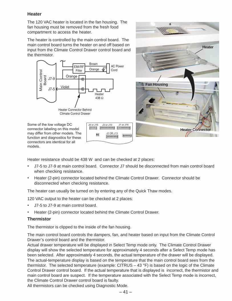
Heater
Heater
The 120 VAC heater is located in the fan housing. Thefan housing must be removed from the fresh foodcompartment to access the heater.
The heater is controlled by the main control board. Themain control board turns the heater on and off based oninput from the Climate Control Drawer control board andthe thermistor.
Heater resistance should be 438 W and can be checked at 2 places:• J7-5 to J7-9 at main control board. Connector J7 should be disconnected from main control board
when checking resistance.• Heater (2-pin) connector located behind the Climate Control Drawer. Connector should be
disconnected when checking resistance.
The heater can usually be turned on by entering any of the Quick Thaw modes.
120 VAC output to the heater can be checked at 2 places:• J7-5 to J7-9 at main control board.• Heater (2-pin) connector located behind the Climate Control Drawer.Thermistor
The thermistor is clipped to the inside of the fan housing.
The main control board controls the dampers, fan, and heater based on input from the Climate ControlDrawer’s control board and the thermistor.Actual drawer temperature will be displayed in Select Temp mode only. The Climate Control Drawerdisplay will show the selected temperature for approximately 4 seconds after a Select Temp mode hasbeen selected. After approximately 4 seconds, the actual temperature of the drawer will be displayed.The actual-temperature display is based on the temperature that the main control board sees from thethermistor. The selected temperature (example: CITRUS – 43 °F) is based on the logic of the ClimateControl Drawer control board. If the actual temperature that is displayed is incorrect, the thermistor andmain control board are suspect. If the temperature associated with the Select Temp mode is incorrect,the Climate Control Drawer control board is faulty.All thermistors can be checked using Diagnostic Mode.
J4 or J16 J3 or J10 J1 or J14
J2 OR J13
Some of the low voltage DC
connector labeling on this model
may differ from other models. The
function and diagnostics for these
connectors are identical for all
models.

– 42 –
ThermistorseulaVrotsimrehT
erutarepmeT)C(seergeD
erutarepmeT)F(seergeD
ecnatsiseRsmho-oliKni
02- 4- k4.84 Ω
01- 41 k6.72 Ω
0 23 k3.61 Ω
01 05 k01 Ω
Access
After removing the diffuser, the thermistor can beaccessed through the hole on the right-hand side ofthe fan. After removing the thermistor from the clip(on the inside of the fan housing), the thermistorcan be removed from the fan housing through thehole in the top of the housing.
Note: When installing the diffuser onto the fanhousing, the tabs must be on the bottom and theflat surface must be on top. Incorrect installationwill prevent the drawer from cooling and warmingproperly.
Note: All thermistors can be checked usingDiagnostic Mode.
Refer to the Thermistor Values chart for resistancevalues. Thermistor resistance can be checked at 2places:• J5-5 to J5-6 at main control board. Connector J5 should be disconnected from main control board
when checking resistance.• 9-pin connector located behind the Climate Control Drawer. Connector should be disconnected
when checking resistance.
5 VDC output to the thermistor can be checked at 2 places:• J5-5 to J5-6 at main control board.• 9-pin connector located behind the Climate Control Drawer.
Clip
9-PinConnector
Thermistor shownremoved from clip.
FanHousing
Tabs (Down)
J4 or J16 J3 or J10 J1 or J14
J2 OR J13
Some of the low voltage DC
connector labeling on this model
may differ from other models. The
function and diagnostics for these
connectors are identical for all
models.

– 43 –
With the dampers open, cold air moves from the FZ compartment through the lower damper and intothe fan housing. The fan blows the cold air through the diffuser into the drawer. The air returns from thedrawer through the diffuser and into the fan housing. Air also moves over the top of the drawer, into theClimate Control Drawer compartment (not into the FF compartment), and then out of the compartmentvia the top damper.
Shown with top panel and drawer removed.
Shown with top panel and drawer removed.
Air Flow
DAMPERS OPEN
DAMPERS CLOSED
With the dampers closed, the fan moves air from the fan housing, through the diffuser, to the drawer. Airreturns from the drawer, through the diffuser, to the fan compartment.

– 44 –
Compartment Lights
The new Monogram side-by-side refrigerator uses 12 VAC halogen lights in both the fresh food andfreezer compartments. The fresh food compartment is equipped with two 35-watt bulbs andfive 20-watt bulbs producing a total of 170 watts. The freezer compartment is equipped with two35-watt bulbs producing a total of 70 watts. Power is supplied to all interior lighting by 2 transformers.The transformers convert 120 VAC to 12 VAC.
FF/FZ Compartment Lights Diagnostic
Check for 120 VAC at transformer. Measurevotlage at transformer connector between redwire (FZ) or violet wire (FF) and orange wire.
Are 120 VAC measured?YES
Check the following:1. FF or FZ door switch2. Sabbath switch3. Circuit breaker (located by the transformers in tray under the FF compartment)4. Thermal overload FZ - located at bottom of FZ Compartment FF - located at bottom of FF light tower5. 120 VAC Wiring FZ - blue wire(s) and red wire(s) FF - yellow wire(s) and violet wires6. Neutral wiring (orange)
NO
ReplaceTransformer.
NO
Open circuitbetween lights and
transformer.
YES
Measure output voltageat transformer
connector between redand gray wires.
Are 12 VAC measured?

– 45 –
Master Light Switch
Light Tower
Fresh Food CompartmentFreezer Compartment
Main ControlBoard CoverMain ControlBoard Cover
Light Tower
Temperature OverloadDevice (TOD)
Temperature OverloadDevice (TOD) Temperature Overload
Device (TOD)Temperature Overload
Device (TOD)
Door Switches
The fresh food and freezer door switches are located at the top of the fresh food and freezercompartments.
The fresh food door switch closes when the door is open, providing L1 to the fresh food compartmentlight transformer.
The freezer door switch is a dual-pole switch. It provides L1 to the main control board when the freezerdoor is closed. When the freezer door is open, the switch provides L1 to the freezer compartment lighttransformer.
Master Light SwitchThe master light switch is located behind the grillepanel, on the main control board cover. Theswitch will open the circuits between the doorswitches and the transformers, disabling bothtransformers and stopping voltage output to theinterior lights.
Temperature Overload Device (TOD)
A temperature overload device is wired in series with both the fresh food and freezer compartmenttransformers. If the interior lights should reach excessive temperatures due to a door being open for anextended period, the corresponding TOD will open the circuit that supplies 120 VAC to the transformer.The TOD will open at 150 °F and close at 90 °F.
The freezer TOD is located behind a metal cover on the back wall of the freezer compartment, at thebase of the light tower. The fresh food TOD is located on the back wall of the fresh food compartment,at the base of the light tower.
Master Light Switch
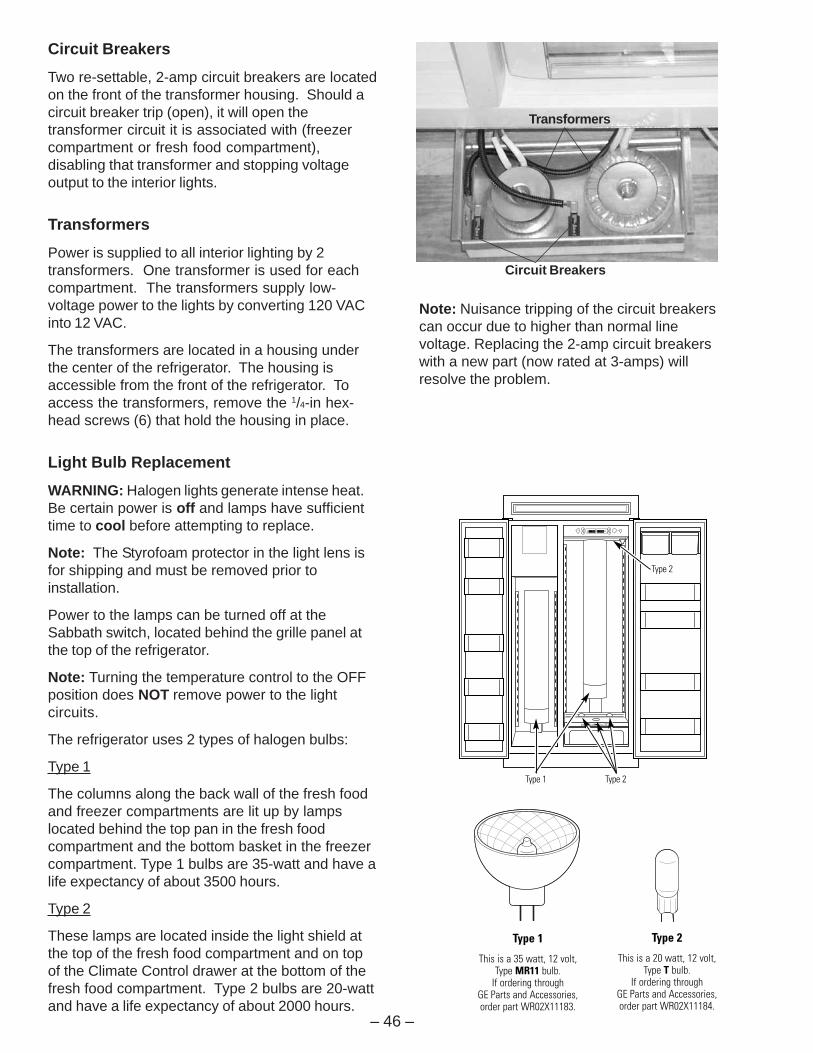
– 46 –
Type 2Type 1
Type 2
Type 1
This is a 35 watt, 12 volt, Type MR11 bulb.
If ordering through GE Parts and Accessories, order part WR02X11183.
Type 2
This is a 20 watt, 12 volt, Type T bulb.
If ordering through GE Parts and Accessories, order part WR02X11184.
Transformers
Circuit Breakers
Circuit Breakers
Two re-settable, 2-amp circuit breakers are locatedon the front of the transformer housing. Should acircuit breaker trip (open), it will open thetransformer circuit it is associated with (freezercompartment or fresh food compartment),disabling that transformer and stopping voltageoutput to the interior lights.
Transformers
Power is supplied to all interior lighting by 2transformers. One transformer is used for eachcompartment. The transformers supply low-voltage power to the lights by converting 120 VACinto 12 VAC.
The transformers are located in a housing underthe center of the refrigerator. The housing isaccessible from the front of the refrigerator. Toaccess the transformers, remove the 1/4-in hex-head screws (6) that hold the housing in place.
Light Bulb Replacement
WARNING: Halogen lights generate intense heat.Be certain power is off and lamps have sufficienttime to cool before attempting to replace.
Note: The Styrofoam protector in the light lens isfor shipping and must be removed prior toinstallation.
Power to the lamps can be turned off at theSabbath switch, located behind the grille panel atthe top of the refrigerator.
Note: Turning the temperature control to the OFFposition does NOT remove power to the lightcircuits.
The refrigerator uses 2 types of halogen bulbs:
Type 1
The columns along the back wall of the fresh foodand freezer compartments are lit up by lampslocated behind the top pan in the fresh foodcompartment and the bottom basket in the freezercompartment. Type 1 bulbs are 35-watt and have alife expectancy of about 3500 hours.
Type 2
These lamps are located inside the light shield atthe top of the fresh food compartment and on topof the Climate Control drawer at the bottom of thefresh food compartment. Type 2 bulbs are 20-wattand have a life expectancy of about 2000 hours.
Note: Nuisance tripping of the circuit breakerscan occur due to higher than normal linevoltage. Replacing the 2-amp circuit breakerswith a new part (now rated at 3-amps) willresolve the problem.

– 47 –
Upper lightshield
ScrewsScrews
Slots
Light housing
Support tabs
Light Shield
Type 1 Bulb Replacement
WARNING: Halogen lights generate intense heat.Be certain power is off and lamps have sufficienttime to cool before attempting to replace.
1. Set the master light switch to the OFF positionand allow the lamps to cool.
2. To access the lamps in the fresh foodcompartment, remove the top pan.
3. Grasp each end of the curved light shield andpull the shield toward you to remove.
4. Remove the glass above the bulbs by pulling itstraight out.
Note: Always follow bulb manufacturer’s directionsfor handling and replacing bulbs.
5. Remove the bulb by holding the base andpulling straight up. Replace with a new bulb.
6. Replace the glass by sliding it into place. Then,replace the light shield by resting the top lip ofthe shield on top of the light housing. Then,press the sides until the tabs pop into the slotsin the housing.
WARNING: The light shield must be replaced, orthe heat from the bulb could damage therefrigerator.
Type 2 Bulb Replacement
WARNING: Halogen lights generate intense heat.Be certain power is off and lamps have sufficienttime to cool before attempting to replace.
1. Set the master light switch to the OFF positionand allow the lamps to cool.
2. If a water filter cartridge is installed, remove itand replace with a filter bypass plug.
3. Holding the light shield with one hand, rotate thesupport tabs until they clear the front of the lightshield. Then, push back on the light shield,lower the shield at the front, and take out.
4. Remove the 4 screws securing the lighthousing to the ceiling. There are two screws atthe front and two at the back.
5. Lower the light housing at the front, then pull ittoward you so the tabs at the back of the lighthousing come out of the slots on the back wall.The lamp assemblies will release from theholders.

– 48 –
Lower lampassemblies
6. Turn the lamp protector to access the bulb.
Note: Always follow bulb manufacturer’s directions forhandling and replacing bulbs.
7. Remove the bulb by holding the base and pullingstraight out. Replace with a new bulb and replace thelamp protector.
WARNING: Lamp protectors must be replaced, or theheat from the bulb could damage the refrigerator.
8. Holding up the light housing, place each lampassembly in its holder. Feed the attached wiresthrough the slots and tuck the wires outside the sideof the light housing.
9. Insert the tabs on the back of the light housing in theslots on the back wall. Raise the light housing intoposition and secure with the four screws.
10. Replace the light shield and rotate the support tabsback out to support the front of the shield.
11. Remove the filter bypass plug and replace with thewater filter cartridge. Reset the Sabbath switch to theON position.
Climate Control Drawer Type 2 Bulb Replacement
WARNING: Halogen lights generate intense heat. Becertain power is off and lamps have sufficient time tocool before attempting to replace.
1. Set the master light switch to the OFF position andallow the lamps to cool.
2. To access the lamps, remove the second producepan.
3. The lamps at the back, which face up, can be liftedout. To access the lamp that shines into the ClimateControl drawer, twist the holder until the arrow pointstoward the back of the refrigerator, then lift up.
4. Turn the lamp protector to access the bulb.
Note: Always follow bulb manufacturer’s directions forhandling and replacing bulbs.
5. Remove the bulb by holding the base and pullingstraight out. Replace with a new bulb and replace thelamp protector.
WARNING: Lamp protectors must be replaced, or theheat from the bulb could damage the refrigerator.
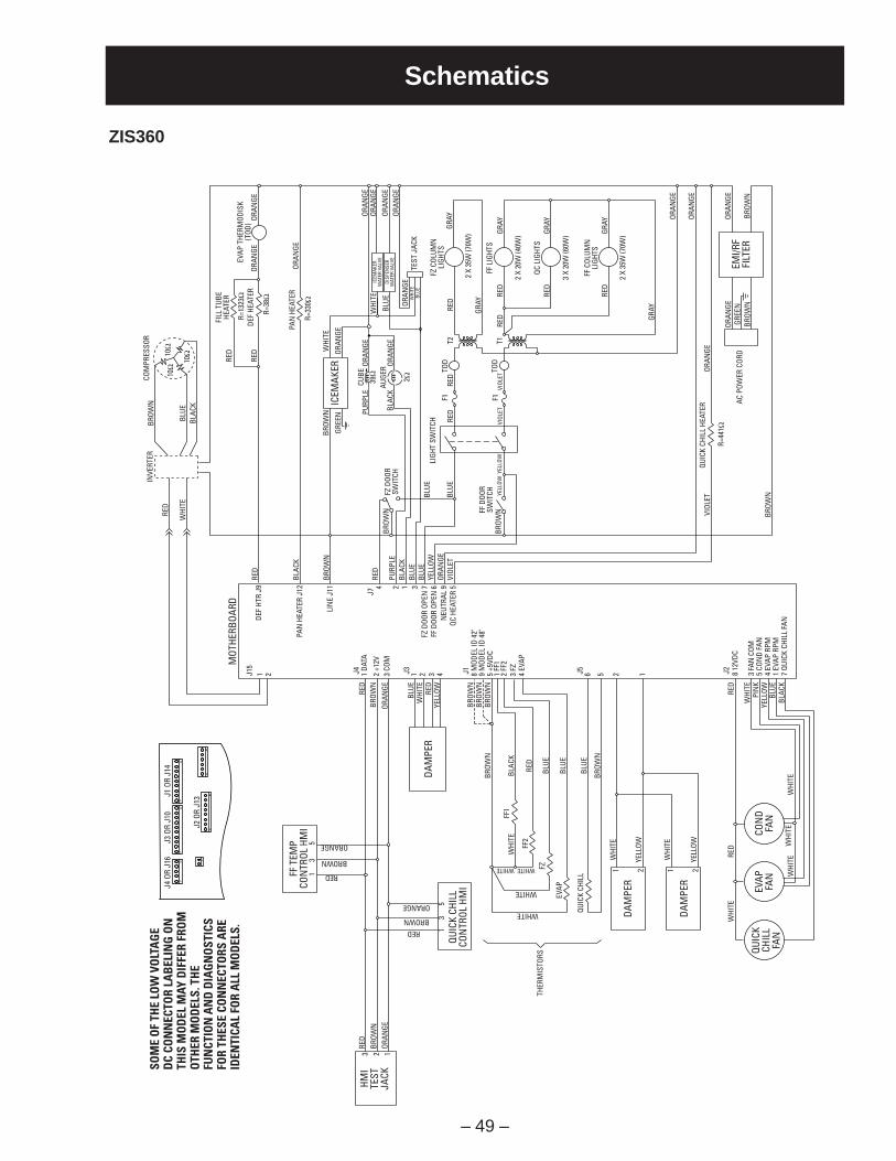
– 49 –
Schematics
ZIS360J4
OR
J16
J3 O
R J1
0J1
OR
J14
J2 O
R J1
3
SOM
E O
F TH
E LO
W V
OLT
AG
ED
C CO
NN
ECTO
R LA
BEL
ING
ON
THIS
MO
DEL
MAY
DIF
FER
FRO
MO
THER
MO
DEL
S. T
HE
FUN
CTIO
N A
ND
DIA
GN
OST
ICS
FOR
THES
E CO
NN
ECTO
RS A
REID
ENTI
CAL
FOR
ALL
MO
DEL
S.
FF T
EMP
CON
TROL
HM
I1 RED
35
BROWN
ORANGE
REDBROWN
ORANGE
RED
3 2 1
BROW
NOR
ANGE
HMI
TEST
JACK
13
5
QUIC
K CH
ILL
CON
TROL
HM
I
RED
BLUE
WHI
TERE
D
RED
RED
WHI
TE
WHI
TE
WHI
TEW
HITE
WHI
TE
PIN
KYE
LLOW
BLUE
BLAC
K
YELL
OW
BROW
NBR
OWN
BROW
NBR
OWN
BLAC
KW
HITE
WHI
TE
WHI
TE
YELL
OW
YELL
OW
WHITE
WHITE
WHITE
WHITE
FF2
FZ
EVAP
QUIC
K CH
ILL
THER
MIS
TORS
FF1
RED
BLUE
BLUE
BLUE
BROW
N
BROW
NOR
ANGE
DAM
PER
MOT
HERB
OARD
J4
J7
J3 J1 J5 J21 DA
TA
DEF
HTR
J9
PAN
HEA
TER
J12
LIN
E J1
1
1 8 M
ODEL
ID 4
2"9
MOD
EL ID
48"
5 +5
VDC
1 FF
12
FF2
3 FZ
4 EV
AP
2 3 4 6 5 2 12 +1
2V3
COM
DAM
PER
DAM
PER
1 2 1 2
8 12
VDC
3 FA
N C
OM5
CON
D FA
N4
EVAP
RPM
1 EV
AP R
PM7
QUIC
K CH
ILL
FAN
QUIC
KCH
ILL
FAN
EVAP
FAN
CON
DFA
N
EMI/R
FFI
LTER
RED
WHI
TE
ICEM
AKER
WAT
ER V
ALVE
DISP
ENSE
RW
ATER
VAL
VE
WHI
TE WHI
TE
BLUE
BLUE
ORAN
GE
BROW
N
GREE
N PURP
LE
BLAC
KAU
GEROR
ANGE
ORAN
GE
RED
RED
ORAN
GE
ORAN
GE
ORAN
GEOR
ANGE
ORAN
GEOR
ANGE
GRAY
GRAY
FF L
IGHT
S
2 X
20W
(40W
)
3 X
20W
(60W
)
2 X
35W
(70W
)
FF C
OLUM
NLI
GHTS
QC L
IGHT
S
GRAY
RED
RED
GRAY
RED
GRAY
GRAY
RED
RED
RED
RED
VIOL
ETVI
OLET
BLUE
BLUE
FF D
OOR
SWIT
CH
T2 T1
TOD
TOD
F1 F1
LIGH
T SW
ITCH
ORAN
GE
ORAN
GE
ORAN
GE
ORAN
GE
ORAN
GEGR
EEN
BROW
N
QUIC
K CH
ILL
HEAT
ER
AC P
OWER
COR
D
VIOL
ET
BROW
N
ORAN
GE
BROW
N
TEST
JAC
K
ORAN
GE
BLAC
K
BROW
N
BROW
N
BROW
N
FZ D
OOR
SWIT
CH
RED
PURP
LEBL
ACK
BLUE
BLUE
YELL
OW
YELL
OWYE
LLOW
ORAN
GEVI
OLET
EVAP
THE
RMOD
ISK
(TOD
)
FILL
TUB
EHE
ATER
DEF
HEAT
ER
PAN
HEA
TER
ICEM
AKER
4 2 1 3FZ
DOO
R OP
EN 7
FF D
OOR
OPEN
6N
EUTR
AL 9
QC H
EATE
R 5
39Ω
2ΩCUBE
FZ C
OLUM
NLI
GHTS
2 X
35W
(70W
)
J15
1 2
BROW
NCO
MPR
ESSO
RIN
VERT
ER
BLUE
RED
WHI
TEBL
ACK
10Ω
10Ω
10Ω
R=44
1Ω
R=33
0Ω
R=38
Ω
R=13
23Ω

– 50 –
ZIS360DSO
ME
OF
THE
LOW
VO
LTA
GE
DC
CON
NEC
TOR
LAB
ELIN
G O
NTH
IS M
OD
EL M
AY D
IFFE
R FR
OM
OTH
ER M
OD
ELS.
TH
EFU
NCT
ION
AN
D D
IAG
NO
STIC
SFO
R TH
ESE
CON
NEC
TORS
ARE
IDEN
TICA
L FO
R A
LL M
OD
ELS.
J4 O
R J1
6J3
OR
J10
J1 O
R J1
4
J2 O
R J1
3
FF T
EMP
CON
TROL
HM
I1 RED
35
BROWN
ORANGE
REDBROWN
ORANGE
RED
3 2 1
BROW
NOR
ANGE
HMI
TEST
JACK
13
5
QUIC
K CH
ILL
CON
TROL
HM
I
RED
BLUE
WHI
TERE
D
RED
RED
WHI
TE
WHI
TE
WHI
TEW
HITE
WHI
TE
PIN
KYE
LLOW
BLUE
BLAC
K
YELL
OW
BROW
NBR
OWN
BROW
NBR
OWN
BLAC
KW
HITE
WHI
TE
WHI
TE
YELL
OW
YELL
OW
WHITE
WHITE
WHITE
WHITE
FF2
FZ
EVAP
QUIC
K CH
ILL
THER
MIS
TORS
FF1
RED
BLUE
BLUE
BLUE
BROW
N
BROW
NOR
ANGE
DAM
PER
MOT
HERB
OARD
J4
J7
J3 J1 J5 J21 DA
TA
DEF
HTR
J9
PAN
HEA
TER
J12
LIN
E J1
1
1 8 M
ODEL
ID 4
2"9
MOD
EL ID
48"
5 +5
VDC
1 FF
12
FF2
3 FZ
4 EV
AP
2 3 4 6 5 2 12 +1
2V3
COM
DAM
PER
DAM
PER
1 2 1 2
8 12
VDC
3 FA
N C
OM5
CON
D FA
N4
EVAP
RPM
1 EV
AP R
PM7
QUIC
K CH
ILL
FAN
QUIC
KCH
ILL
FAN
EVAP
FAN
CON
DFA
N
EMI/R
FFI
LTER
RED
WHI
TE
ICEM
AKER
WAT
ER V
ALVE
DISP
ENSE
RW
ATER
VAL
VE
WHI
TE WHI
TE
BLUE
BLUE
ORAN
GE
BROW
N
GREE
N PURP
LE
BLAC
KAU
GEROR
ANGE
ORAN
GE
RED
RED
ORAN
GE
ORAN
GE
ORAN
GEOR
ANGE
ORAN
GEOR
ANGE
GRAY
GRAY
FF L
IGHT
S
2 X
20W
(40W
)
3 X
20W
(60W
)
2 X
35W
(70W
)
FF C
OLUM
NLI
GHTS
QC L
IGHT
S
GRAY
RED
RED
GRAY
RED
GRAY
GRAY
RED
RED
RED
RED
VIOL
ETVI
OLET
BLUE
BLUE
FF D
OOR
SWIT
CH
T2 T1
TOD
TOD
F1 F1
LIGH
T SW
ITCH
ORAN
GE
ORAN
GE
ORAN
GE
ORAN
GE
ORAN
GEGR
EEN
BROW
N
QUIC
K CH
ILL
HEAT
ER
R=44
1Ω
AC P
OWER
COR
D
VIOL
ET
BROW
N
ORAN
GE
BROW
N
TEST
JAC
K
ORAN
GE
BLAC
K
BROW
N
BROW
N
BROW
N
FZ D
OOR
SWIT
CH
RED
PURP
LEBL
ACK
BLUE
BLUE
YELL
OW
YELL
OWYE
LLOW
ORAN
GEVI
OLET
EVAP
THE
RMOD
ISK
(TOD
)
FILL
TUB
EHE
ATER
DEF
HEAT
ERR=
1323
Ω
PAN
HEA
TER
R=33
0Ω
R=38
Ω
ICEM
AKER
4 2 1 3FZ
DOO
R OP
EN 7
FF D
OOR
OPEN
6N
EUTR
AL 9
QC H
EATE
R 5
39Ω
2ΩCUBE
FZ C
OLUM
NLI
GHTS
2 X
35W
(70W
)
J15
1 2
BROW
NCO
MPR
ESSO
RIN
VERT
ER
BLUE
RED
WHI
TEBL
ACK
10Ω
10Ω
10Ω
DISP
ENSE
RCO
NTR
OL H
MI
1 RED
35
BROWN
ORANGE

– 51 –
ZIS420
J4 O
R J1
6J3
OR
J10
J1 O
R J1
4
J2 O
R J1
3
SOM
E O
F TH
E LO
W V
OLT
AG
ED
C CO
NN
ECTO
R LA
BEL
ING
ON
THIS
MO
DEL
MAY
DIF
FER
FRO
MO
THER
MO
DEL
S. T
HE
FUN
CTIO
N A
ND
DIA
GN
OST
ICS
FOR
THES
E CO
NN
ECTO
RS A
REID
ENTI
CAL
FOR
ALL
MO
DEL
S.
FF T
EMP
CON
TROL
HM
I1 RED
35
BROWN
ORANGE
REDBROWN
ORANGE
RED
3 2 1
BROW
NOR
ANGE
HMI
TEST
JACK
13
5
QUIC
K CH
ILL
CON
TROL
HM
I
RED
BLUE
WHI
TERE
D
RED
RED
WHI
TE
WHI
TE
WHI
TEW
HITE
WHI
TE
PIN
KYE
LLOW
BLUE
BLAC
K
YELL
OW
BROW
NBR
OWN
BROW
NBR
OWN
BLAC
KW
HITE
WHI
TE
WHI
TE
YELL
OW
YELL
OW
WHITE
WHITE
WHITE
WHITE
FF2
FZ
EVAP
QUIC
K CH
ILL
THER
MIS
TORS
FF1
RED
BLUE
BLUE
BLUE
BROW
N
BROW
NOR
ANGE
DAM
PER
MOT
HERB
OARD
J4
J7
J3 J1 J5 J21 DA
TA
DEF
HTR
J9
PAN
HEA
TER
J12
LIN
E J1
1
1 8 M
ODEL
ID 4
2"9
MOD
EL ID
48"
5 +5
VDC
1 FF
12
FF2
3 FZ
4 EV
AP
2 3 4 6 5 2 12 +1
2V3
COM
DAM
PER
DAM
PER
1 2 1 2
8 12
VDC
3 FA
N C
OM5
CON
D FA
N4
EVAP
RPM
1 EV
AP R
PM7
QUIC
K CH
ILL
FAN
QUIC
KCH
ILL
FAN
EVAP
FAN
CON
DFA
N
EMI/R
FFI
LTER
RED
WHI
TE
ICEM
AKER
WAT
ER V
ALVE
DISP
ENSE
RW
ATER
VAL
VE
WHI
TE WHI
TE
BLUE
BLUE
ORAN
GE
BROW
N
GREE
N PURP
LE
BLAC
KAU
GEROR
ANGE
ORAN
GE
RED
RED
ORAN
GE
ORAN
GE
ORAN
GEOR
ANGE
ORAN
GEOR
ANGE
GRAY
GRAY
FF L
IGHT
S
2 X
20W
(40W
)
3 X
20W
(60W
)
2 X
35W
(70W
)
FF C
OLUM
NLI
GHTS
QC L
IGHT
S
GRAY
RED
RED
GRAY
RED
GRAY
GRAY
RED
RED
RED
RED
VIOL
ETVI
OLET
BLUE
BLUE
FF D
OOR
SWIT
CH
T2 T1
TOD
TOD
F1 F1
LIGH
T SW
ITCH
ORAN
GE
ORAN
GE
ORAN
GE
ORAN
GE
ORAN
GEGR
EEN
BROW
N
QUIC
K CH
ILL
HEAT
ER
R=44
1Ω
AC P
OWER
COR
D
VIOL
ET
BROW
N
ORAN
GE
BROW
N
TEST
JAC
K
ORAN
GE
BLAC
K
BROW
N
BROW
N
BROW
N
FZ D
OOR
SWIT
CH
RED
PURP
LEBL
ACK
BLUE
BLUE
YELL
OW
YELL
OWYE
LLOW
ORAN
GEVI
OLET
EVAP
THE
RMOD
ISK
(TOD
)
FILL
TUB
EHE
ATER
DEF
HEAT
ER
R=38
Ω
R=13
23Ω
PAN
HEA
TER
R=33
0Ω
ICEM
AKER
4 2 1 3FZ
DOO
R OP
EN 7
FF D
OOR
OPEN
6N
EUTR
AL 9
QC H
EATE
R 5
39Ω
2ΩCUBE
FZ C
OLUM
NLI
GHTS
2 X
35W
(70W
)
J15
1 2
BROW
NCO
MPR
ESSO
RIN
VERT
ER
BLUE
RED
WHI
TEBL
ACK
10Ω
10Ω
10Ω

– 52 –
ZIS420DSO
ME
OF
THE
LOW
VO
LTA
GE
DC
CON
NEC
TOR
LAB
ELIN
G O
NTH
IS M
OD
EL M
AY D
IFFE
R FR
OM
OTH
ER M
OD
ELS.
TH
EFU
NCT
ION
AN
D D
IAG
NO
STIC
SFO
R TH
ESE
CON
NEC
TORS
ARE
IDEN
TICA
L FO
R A
LL M
OD
ELS.
J4 O
R J1
6J3
OR
J10
J1 O
R J1
4
J2 O
R J1
3
FF T
EMP
CON
TROL
HM
I1 RED
35
BROWN
ORANGE
REDBROWN
ORANGERE
D3 2 1
BROW
NOR
ANGE
HMI
TEST
JACK
13
5
QUIC
K CH
ILL
CON
TROL
HM
I
RED
BLUE
WHI
TERE
D
RED
RED
WHI
TE
WHI
TE
WHI
TEW
HITE
WHI
TE
PIN
KYE
LLOW
BLUE
BLAC
K
YELL
OW
BROW
NBR
OWN
BROW
NBR
OWN
BLAC
KW
HITE
WHI
TE
WHI
TE
YELL
OW
YELL
OW
WHITE
WHITE
WHITE
WHITE
FF2
FZ
EVAP
QUIC
K CH
ILL
THER
MIS
TORS
FF1
RED
BLUE
BLUE
BLUE
BROW
N
BROW
NOR
ANGE
DAM
PER
MOT
HERB
OARD
J4
J7
J3 J1 J5 J21 DA
TA
DEF
HTR
J9
PAN
HEA
TER
J12
LIN
E J1
1
1 8 M
ODEL
ID 4
2"9
MOD
EL ID
48"
5 +5
VDC
1 FF
12
FF2
3 FZ
4 EV
AP
2 3 4 6 5 2 12 +1
2V3
COM
DAM
PER
DAM
PER
1 2 1 2
8 12
VDC
3 FA
N C
OM5
CON
D FA
N4
EVAP
RPM
1 EV
AP R
PM7
QUIC
K CH
ILL
FAN
QUIC
KCH
ILL
FAN
EVAP
FAN
CON
DFA
N
EMI/R
FFI
LTER
RED
WHI
TE
ICEM
AKER
WAT
ER V
ALVE
DISP
ENSE
RW
ATER
VAL
VE
WHI
TE WHI
TE
BLUE
BLUE
ORAN
GE
BROW
N
GREE
N PURP
LE
BLAC
KAU
GEROR
ANGE
ORAN
GE
RED
RED
ORAN
GE
ORAN
GE
ORAN
GEOR
ANGE
ORAN
GEOR
ANGE
GRAY
GRAY
FF L
IGHT
S
2 X
20W
(40W
)
3 X
20W
(60W
)
2 X
35W
(70W
)
FF C
OLUM
NLI
GHTS
QC L
IGHT
S
GRAY
RED
RED
GRAY
RED
GRAY
GRAY
RED
RED
RED
RED
VIOL
ETVI
OLET
BLUE
BLUE
FF D
OOR
SWIT
CH
T2 T1
TOD
TOD
F1 F1
LIGH
T SW
ITCH
ORAN
GE
ORAN
GE
ORAN
GE
ORAN
GE
ORAN
GEGR
EEN
BROW
N
QUIC
K CH
ILL
HEAT
ER
R=44
1Ω
AC P
OWER
COR
D
VIOL
ET
BROW
N
ORAN
GE
BROW
N
TEST
JAC
K
ORAN
GE
BLAC
K
BROW
N
BROW
N
BROW
N
FZ D
OOR
SWIT
CH
RED
PURP
LEBL
ACK
BLUE
BLUE
YELL
OW
YELL
OWYE
LLOW
ORAN
GEVI
OLET
EVAP
THE
RMOD
ISK
(TOD
)
FILL
TUB
EHE
ATER
R=13
23Ω
DEF
HEAT
ER
R=38
Ω
PAN
HEA
TER
R=33
0Ω
ICEM
AKER
4 2 1 3FZ
DOO
R OP
EN 7
FF D
OOR
OPEN
6N
EUTR
AL 9
QC H
EATE
R 5
39Ω
2ΩCUBE
FZ C
OLUM
NLI
GHTS
2 X
35W
(70W
)
J15
1 2
BROW
NCO
MPR
ESSO
RIN
VERT
ER
BLUE
RED
WHI
TEBL
ACK
10Ω
10Ω
10Ω
DISP
ENSE
RCO
NTR
OL H
MI
1 RED
35
BROWN
ORANGE
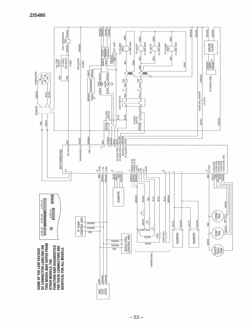
– 53 –
ZIS480
SOM
E O
F TH
E LO
W V
OLT
AG
ED
C CO
NN
ECTO
R LA
BEL
ING
ON
THIS
MO
DEL
MAY
DIF
FER
FRO
MO
THER
MO
DEL
S. T
HE
FUN
CTIO
N A
ND
DIA
GN
OST
ICS
FOR
THES
E CO
NN
ECTO
RS A
REID
ENTI
CAL
FOR
ALL
MO
DEL
S.
J4 O
R J1
6J3
OR
J10
J1 O
R J1
4
J2 O
R J1
3
FF T
EMP
CON
TROL
HM
I1 RED
35
BROWN
ORANGE
REDBROWN
ORANGE
RED
3 2 1
BROW
NOR
ANGE
HMI
TEST
JACK
13
5
QUIC
K CH
ILL
CON
TROL
HM
I
RED
BLUE
WHI
TERE
D
RED
RED
WHI
TE
WHI
TE
WHI
TEW
HITE
WHI
TE
PIN
KYE
LLOW
BLUE
BLAC
K
YELL
OW
BROW
NBR
OWN
BROW
NBR
OWN
BLAC
KW
HITE
WHI
TE
WHI
TE
YELL
OW
YELL
OW
WHITE
WHITE
WHITE
WHITE
FF2
FZ
EVAP
QUIC
K CH
ILL
THER
MIS
TORS
FF1
RED
BLUE
BLUE
BLUE
BROW
N
BROW
NOR
ANGE
DAM
PER
MOT
HERB
OARD
J4
J7
J3 J1 J5 J21 DA
TA
DEF
HTR
J9
PAN
HEA
TER
J12
LIN
E J1
1
1 8 M
ODEL
ID 4
2"9
MOD
EL ID
48"
5 +5
VDC
1 FF
12
FF2
3 FZ
4 EV
AP
2 3 4 6 5 2 12 +1
2V3
COM
DAM
PER
DAM
PER
1 2 1 2
8 12
VDC
3 FA
N C
OM5
CON
D FA
N4
EVAP
RPM
1 EV
AP R
PM7
QUIC
K CH
ILL
FAN
QUIC
KCH
ILL
FAN
EVAP
FAN
CON
DFA
N
EMI/R
FFI
LTER
RED
WHI
TE
ICEM
AKER
WAT
ER V
ALVE
DISP
ENSE
RW
ATER
VAL
VE
WHI
TE WHI
TE
BLUE
BLUE
ORAN
GE
BROW
N
GREE
N PURP
LE
BLAC
KAU
GEROR
ANGE
ORAN
GE
RED
RED
ORAN
GE
ORAN
GE
ORAN
GEOR
ANGE
ORAN
GEOR
ANGE
GRAY
GRAY
FF L
IGHT
S
2 X
20W
(40W
)
3 X
20W
(60W
)
2 X
35W
(70W
)
FF C
OLUM
NLI
GHTS
QC L
IGHT
S
GRAY
RED
RED
GRAY
RED
GRAY
GRAY
RED
RED
RED
RED
VIOL
ETVI
OLET
BLUE
BLUE
FF D
OOR
SWIT
CH
T2 T1
TOD
TOD
F1 F1
LIGH
T SW
ITCH
ORAN
GE
ORAN
GE
ORAN
GE
ORAN
GE
ORAN
GEGR
EEN
BROW
N
QUIC
K CH
ILL
HEAT
ER
AC P
OWER
COR
D
VIOL
ET
BROW
N
ORAN
GE
BROW
N
TEST
JAC
K
ORAN
GE
BLAC
K
BROW
N
BROW
N
BROW
N
FZ D
OOR
SWIT
CH
RED
PURP
LEBL
ACK
BLUE
BLUE
YELL
OW
YELL
OWYE
LLOW
ORAN
GEVI
OLET
EVAP
THE
RMOD
ISK
(TOD
)
FILL
TUB
EHE
ATER
R=13
23Ω
DEF
HEAT
ER
R=38
Ω
PAN
HEA
TER
R=33
0Ω
ICEM
AKER
4 2 1 3FZ
DOO
R OP
EN 7
FF D
OOR
OPEN
6N
EUTR
AL 9
QC H
EATE
R 5
39Ω
2ΩCUBE
FZ C
OLUM
NLI
GHTS
2 X
35W
(70W
)
J15
1 2
BROW
NCO
MPR
ESSO
RIN
VERT
ER
BLUE
RED
WHI
TEBL
ACK
10Ω
10Ω
10Ω
R=44
1Ω
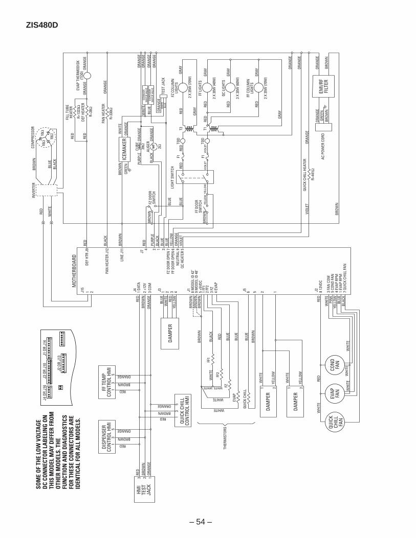
– 54 –
ZIS480DSO
ME
OF
THE
LOW
VO
LTA
GE
DC
CON
NEC
TOR
LAB
ELIN
G O
NTH
IS M
OD
EL M
AY D
IFFE
R FR
OM
OTH
ER M
OD
ELS.
TH
EFU
NCT
ION
AN
D D
IAG
NO
STIC
SFO
R TH
ESE
CON
NEC
TORS
ARE
IDEN
TICA
L FO
R A
LL M
OD
ELS.
J4 O
R J1
6J3
OR
J10
J1 O
R J1
4
J2 O
R J1
3
FF T
EMP
CON
TROL
HM
I1 RED
35
BROWN
ORANGE
REDBROWN
ORANGE
RED
3 2 1
BROW
NOR
ANGE
HMI
TEST
JACK
13
5
QUIC
K CH
ILL
CON
TROL
HM
I
RED
BLUE
WHI
TERE
D
RED
RED
WHI
TE
WHI
TE
WHI
TEW
HITE
WHI
TE
PIN
KYE
LLOW
BLUE
BLAC
K
YELL
OW
BROW
NBR
OWN
BROW
NBR
OWN
BLAC
KW
HITE
WHI
TE
WHI
TE
YELL
OW
YELL
OW
WHITE
WHITE
WHITE
WHITE
FF2
FZ
EVAP
QUIC
K CH
ILL
THER
MIS
TORS
FF1
RED
BLUE
BLUE
BLUE
BROW
N
BROW
NOR
ANGE
DAM
PER
MOT
HERB
OARD
J4
J7
J3 J1 J5 J21 DA
TA
DEF
HTR
J9
PAN
HEA
TER
J12
LIN
E J1
1
1 8 M
ODEL
ID 4
2"9
MOD
EL ID
48"
5 +5
VDC
1 FF
12
FF2
3 FZ
4 EV
AP
2 3 4 6 5 2 12 +1
2V3
COM
DAM
PER
DAM
PER
1 2 1 2
8 12
VDC
3 FA
N C
OM5
CON
D FA
N4
EVAP
RPM
1 EV
AP R
PM7
QUIC
K CH
ILL
FAN
QUIC
KCH
ILL
FAN
EVAP
FAN
CON
DFA
N
EMI/R
FFI
LTER
RED
WHI
TE
ICEM
AKER
WAT
ER V
ALVE
DISP
ENSE
RW
ATER
VAL
VE
WHI
TE WHI
TE
BLUE
BLUE
ORAN
GE
BROW
N
GREE
N PURP
LE
BLAC
KAU
GEROR
ANGE
ORAN
GE
RED
RED
ORAN
GE
ORAN
GE
ORAN
GEOR
ANGE
ORAN
GEOR
ANGE
GRAY
GRAY
FF L
IGHT
S
2 X
20W
(40W
)
3 X
20W
(60W
)
2 X
35W
(70W
)
FF C
OLUM
NLI
GHTS
QC L
IGHT
S
GRAY
RED
RED
GRAY
RED
GRAY
GRAY
RED
RED
RED
RED
VIOL
ETVI
OLET
BLUE
BLUE
FF D
OOR
SWIT
CH
T2 T1
TOD
TOD
F1 F1
LIGH
T SW
ITCH
ORAN
GE
ORAN
GE
ORAN
GE
ORAN
GE
ORAN
GEGR
EEN
BROW
N
QUIC
K CH
ILL
HEAT
ER
R=44
1Ω
AC P
OWER
COR
D
VIOL
ET
BROW
N
ORAN
GE
BROW
N
TEST
JAC
K
ORAN
GE
BLAC
K
BROW
N
BROW
N
BROW
N
FZ D
OOR
SWIT
CH
RED
PURP
LEBL
ACK
BLUE
BLUE
YELL
OW
YELL
OWYE
LLOW
ORAN
GEVI
OLET
EVAP
THE
RMOD
ISK
(TOD
)
FILL
TUB
EHE
ATER
R=13
23Ω
DEF
HEAT
ER
R=38
Ω
PAN
HEA
TER
R=33
0Ω
ICEM
AKER
4 2 1 3FZ
DOO
R OP
EN 7
FF D
OOR
OPEN
6N
EUTR
AL 9
QC H
EATE
R 5
39Ω
2ΩCUBE
FZ C
OLUM
NLI
GHTS
2 X
35W
(70W
)
J15
1 2
BROW
NCO
MPR
ESSO
RIN
VERT
ER
BLUE
RED
WHI
TEBL
ACK
10Ω
10Ω
10Ω
DISP
ENSE
RCO
NTR
OL H
MI
1 RED
35
BROWN
ORANGE

– 55 –
Refrigeration System
Inverter Compressor
The new inverter compressor is notcontrolled by 120 VAC output fromthe main control board, as inprevious models. The compressoris controlled by the inverter.
Warning: Disconnecting the 6-pinconnector does not disconnectpower (120 VAC) from the inverter.The refrigerator must be unpluggedbefore servicing the inverter orcompressor.
Caution: Do not attempt todirect-start the compressor.The compressor operates on a3-phase power supply. Applying120 VAC to the compressor will permanently damage the unit. It is not possible to start thecompressor without an inverter.
The compressor is a reciprocating, variable speed, 4-pole type. It operates on 3-phase, 80 to 230 VACwithin a range of 57 to 104 Hz. Compressor speed is controlled by voltage frequency and pulse widthmodulation. Increasing frequency from the inverter will produce an increase in compressor speed.
• Frequency of 57 Hz will produce low speed operation at 1710 rpm.
• Frequency of 70 Hz will produce medium speed at 2100 rpm.
• Frequency of 104 Hz will produce 3120 rpm.
Note: Certain voltmeters will not be able to read voltage output or frequency from the inverter.
Compressor wattages at various speeds are:• LOW - 65 watts• MED - 100 watts• HIGH - 150 watts
BTU rating also varies according to operating speed.
Compressor speed is based on the temperature set-point in conjunction with the cabinet temperature.Speeds are selected according to the following cabinet temperatures:• 6 °F to 19.5 °F above set-point = high speed• 3.5 °F to 5.5 °F above set-point = medium speed• 1 °F to 3 °F above set-point = low speedNote: The compressor will run at medium speed if the cabinet temperature is 20 °F or more above theset-point.The use of 3-phase power eliminates the need for the PTCR relay, capacitor, and individual start and runwindings; therefore the start, run, and common pins found on conventional compressors are notapplicable on this 3-phase model. Compressor pin functions are identical and compressor lead wireconfiguration is of no importance. A resistance of 9 to 11 W should be read between any 2 of the 3 pins.Should an open occur in the compressor winding or should one of the compressor lead wires becomeopen or disconnected, the inverter will stop voltage output to the compressor.
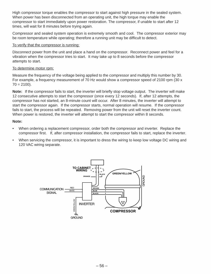
– 56 –
High compressor torque enables the compressor to start against high pressure in the sealed system.When power has been disconnected from an operating unit, the high torque may enable thecompressor to start immediately upon power restoration. The compressor, if unable to start after 12times, will wait for 8 minutes before trying again.
Compressor and sealed system operation is extremely smooth and cool. The compressor exterior maybe room temperature while operating; therefore a running unit may be difficult to detect.
To verify that the compressor is running:
Disconnect power from the unit and place a hand on the compressor. Reconnect power and feel for avibration when the compressor tries to start. It may take up to 8 seconds before the compressorattempts to start.
To determine motor rpm:
Measure the frequency of the voltage being applied to the compressor and multiply this number by 30.For example, a frequency measurement of 70 Hz would show a compressor speed of 2100 rpm (30 x70 = 2100).
Note: If the compressor fails to start, the inverter will briefly stop voltage output. The inverter will make12 consecutive attempts to start the compressor (once every 12 seconds). If, after 12 attempts, thecompressor has not started, an 8-minute count will occur. After 8 minutes, the inverter will attempt tostart the compressor again. If the compressor starts, normal operation will resume. If the compressorfails to start, the process will be repeated. Removing power from the unit will reset the inverter count.When power is restored, the inverter will attempt to start the compressor within 8 seconds.
Note:
• When ordering a replacement compressor, order both the compressor and inverter. Replace thecompressor first. If, after compressor installation, the compressor fails to start, replace the inverter.
• When servicing the compressor, it is important to dress the wiring to keep low voltage DC wiring and120 VAC wiring separate.

– 57 –
Inverter
Warning: Disconnecting the 6-pin connector does not disconnect power (120 VAC) from theinverter. The refrigerator must be unplugged before servicing the inverter.
Note: Certain voltmeters will not be able to read voltage output from the inverter. If no voltage or erraticvoltage is measured, it does not necessarily indicate a faulty inverter.
The inverter receives 120 VAC line-in from the power supply. The inverter converts this single-phase,60 Hz, 120 VAC into 3-phase, 230 VAC, with frequency variations between 57 Hz and 104 Hz. Thisvoltage is delivered to the compressor through 3 lead wires. Each wire will carry identical voltage andfrequency. When checking inverter voltage output, connect the test-meter leads to any 2 of the 3compressor lead wires. The same reading should be measured between any 2 of the 3 wires.
Note: The compressor leads must be connected to measure voltage output. If the compressor wiresare not connected, or if an open occurs in one of the 3 lead wires or in the compressor, the inverter willstop voltage output.
The inverter controls compressor speed by frequency variation and by pulse width modulation (PWM).Changing frequency and PWM will cause an effective voltage between 80 and 230 VAC to be received atthe compressor.
• Low speed (1710 rpm) - 57 Hz
• Medium speed (2100 rpm) - 70 Hz
• High Speed (3120 rpm) - 104 Hz
The inverter receives commands from the main control board.The main control board will send a (PWM) run signal between 1.5and 3.5 VDC effective voltage to the inverter. The signal voltage atthe inverter should be equal to the signal voltage sent by the maincontrol board. The inverter will select compressor speed (voltageoutput) based on this signal. A signal voltage from the maincontrol board (J15 connector ) lower than 5 VDC indicates afaulty main control board. The main control board will only send arun signal to the inverter when the compressor should be on.
Note: When measuring signal voltage (from the main controlboard) at the inverter, disconnect the wire harness connector atthe inverter and measure the voltage at the connector.
The inverter will monitor compressor operation and if thecompressor fails to start or excessive current draw (4 ampsmaximum) is detected, the inverter will briefly stop voltage output.The inverter will then make 12 consecutive compressor startattempts (once every 12 seconds). If after 12 attempts thecompressor has not started, an 8-minute count will initiate. Afterthe 8-minute count, the inverter will attempt to start thecompressor again. If the compressor starts, normal operation willresume. If the compressor fails to start, this process will be repeated. Removing power to the unit willreset the inverter count. When power is restored, the inverter will attempt to start the compressor within8 seconds.
The inverter has a built-in circuit protection to guard against damage from a failed or shortedcompressor. However, if a failed compressor is diagnosed, order a new compressor and inverter. If thecompressor fails to start after replacement, replace the inverter.
J15
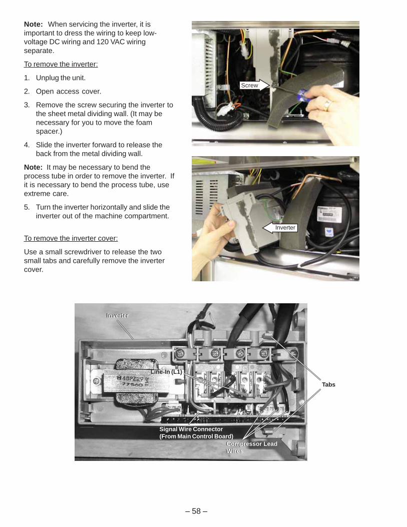
– 58 –
Note: When servicing the inverter, it isimportant to dress the wiring to keep low-voltage DC wiring and 120 VAC wiringseparate.
To remove the inverter:
1. Unplug the unit.
2. Open access cover.
3. Remove the screw securing the inverter tothe sheet metal dividing wall. (It may benecessary for you to move the foamspacer.)
4. Slide the inverter forward to release theback from the metal dividing wall.
Note: It may be necessary to bend theprocess tube in order to remove the inverter. Ifit is necessary to bend the process tube, useextreme care.
5. Turn the inverter horizontally and slide theinverter out of the machine compartment.
To remove the inverter cover:
Use a small screwdriver to release the twosmall tabs and carefully remove the invertercover.
Compressor LeadWiresCompressor LeadWires
Signal Wire Connector(From Main Control Board)
Inverter Inverter
Signal Wire Connector(From Main Control Board)
Line-In (L1) Line-In (L1)
Tabs
Inverter
Screw
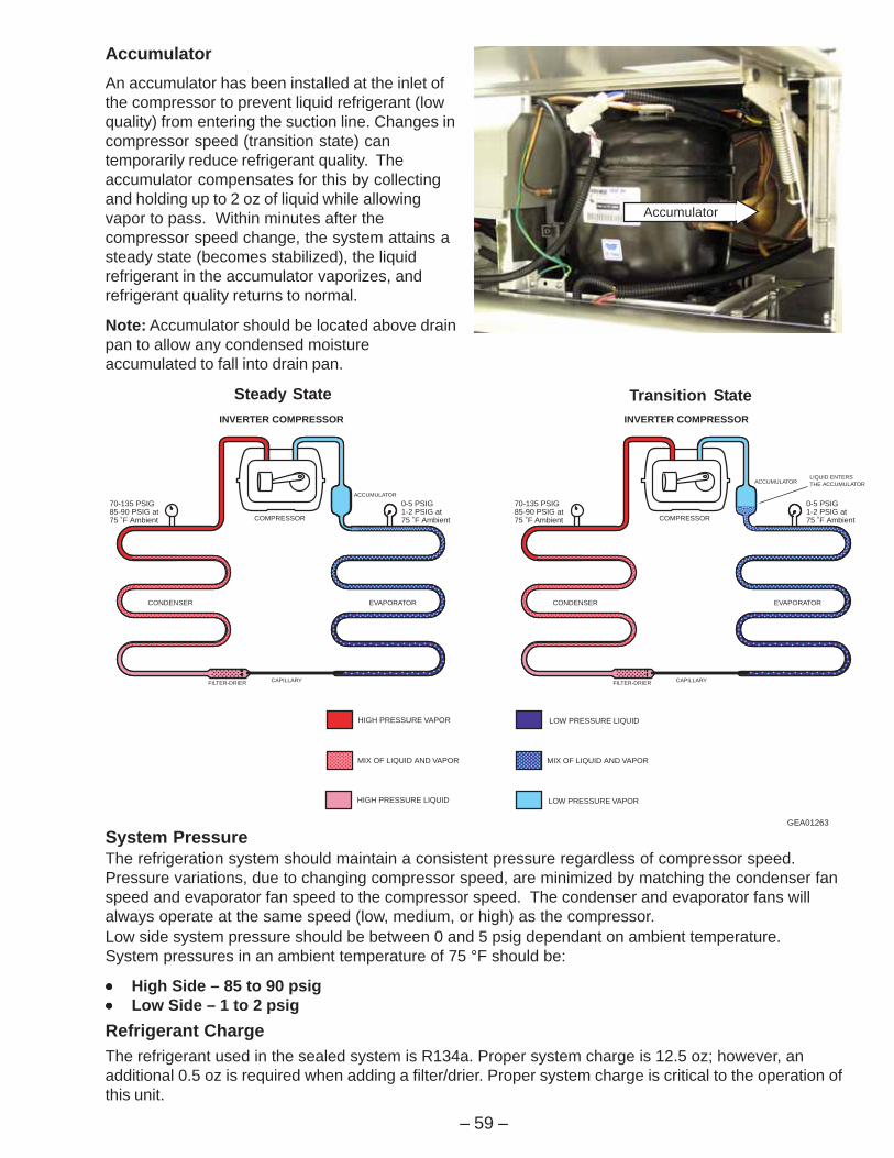
– 59 –
System PressureThe refrigeration system should maintain a consistent pressure regardless of compressor speed.Pressure variations, due to changing compressor speed, are minimized by matching the condenser fanspeed and evaporator fan speed to the compressor speed. The condenser and evaporator fans willalways operate at the same speed (low, medium, or high) as the compressor.Low side system pressure should be between 0 and 5 psig dependant on ambient temperature.System pressures in an ambient temperature of 75 °F should be:
••••• High Side – 85 to 90 psig••••• Low Side – 1 to 2 psigRefrigerant ChargeThe refrigerant used in the sealed system is R134a. Proper system charge is 12.5 oz; however, anadditional 0.5 oz is required when adding a filter/drier. Proper system charge is critical to the operation ofthis unit.
HIGH PRESSURE VAPOR
HIGH PRESSURE LIQUID
LOW PRESSURE LIQUID
LOW PRESSURE VAPOR
MIX OF LIQUID AND VAPOR MIX OF LIQUID AND VAPOR
INVERTER COMPRESSOR
0-5 PSIG1-2 PSIG at75 ˚F Ambient
70-135 PSIG85-90 PSIG at75 ˚F Ambient COMPRESSOR
CONDENSER EVAPORATOR
CAPILLARYFILTER-DRIER
ACCUMULATOR
INVERTER COMPRESSOR
0-5 PSIG1-2 PSIG at75 ˚F Ambient
70-135 PSIG85-90 PSIG at75 ˚F Ambient COMPRESSOR
CONDENSER EVAPORATOR
CAPILLARYFILTER-DRIER
ACCUMULATORLIQUID ENTERSTHE ACCUMULATOR
GEA01263
Steady State Transition State
AccumulatorAn accumulator has been installed at the inlet ofthe compressor to prevent liquid refrigerant (lowquality) from entering the suction line. Changes incompressor speed (transition state) cantemporarily reduce refrigerant quality. Theaccumulator compensates for this by collectingand holding up to 2 oz of liquid while allowingvapor to pass. Within minutes after thecompressor speed change, the system attains asteady state (becomes stabilized), the liquidrefrigerant in the accumulator vaporizes, andrefrigerant quality returns to normal.
Note: Accumulator should be located above drainpan to allow any condensed moistureaccumulated to fall into drain pan.
Accumulator

– 60 –
DrierThe drier is positioned vertically in the center of themachine compartment. A copper process tube,connected to the inlet of the drier, provides accessto the high-pressure side of the refrigerationsystem. The capillary is connected to the outlet ofthe drier.
EvaporatorThe evaporator is made of copper and aluminumand is located above the evaporator fan at the top ofthe freezer compartment.
To replace the evaporator
1. Recover the refrigerant.
2. Remove the evaporator fan (see procedure).
3. Remove the defrost heater (see procedure).
4. Remove the defrost overtemperaturethermodisc and evaporator thermistor.
5. Disconnect the ground wire from the evaporatorand position all wiring to allow for evaporatorremoval.
6. Remove the screws securing the evaporator tothe cabinet.
Caution: Protect wiring from heat duringdesoldering and resoldering.
7. Desolder the capillary tube from the evaporator.
8. Desolder the suction line.
9. Remove the evaporator.
10. Using a file, score the capillary tube just above theold solder and break the solder-covered sectionoff. This will help prevent the capillary tube frombecoming plugged when resoldering.
11. Position the new evaporator in the cabinet.Insert the suction line and capillary tube into theevaporator.
12. Solder the suction line to the evaporator usingsilfos.
13. Solder the capillary tube to the evaporator usingsilfos.
14. Install a replacement drier.
15. Evacuate and recharge the system usingcurrently accepted procedures.
Drier
ProcessTube
Capillary
Defrost Overtemperature Thermodisc
Evaporator ThermistorEvaporator Thermistor
Refrigerant ChargeThe refrigerant used in this model is type R134a.Refer to the mini-manual or model tag for theexact refrigerant charge quantity.

– 61 –
Enter the diagnostic mode by pressing both the freezer temperature pads (plus and minus) and therefrigerator temperature pads (plus and minus) simultaneously. All 4 pads must be held forapproximately 3 seconds. A blinking “0” in both displays indicate the refrigerator has entered the testmode.
Enter the appropriate display numbers asshown below and press any pad other than thetemperature pads to activate that test mode.
Note 1: Display order is: 1) Fresh Food 1, 2) Fresh Food 2, 3) Custom Cool, 4) Evaporator,5) Freezer. Thermistor test results are P = pass, 0 = fail, S = short to 5 VDC, B = bad amplifier(replace main control).
Note 2: You must enter the defrost test again to toggle the defrost heater off at the end of the test.The heater will not come on if the evaporator thermistor or overtemperature thermodisc is warm.
Diagnostic Mode
rezeerFyalpsiD
dooFhserFyalpsiD scitsongaiD stluseR stnemmoC
0 1 .edoMmoorwohS .edommoorwohsnitinU otdenepoerdnadesolcebtsumroodFF.edommoorwohstrats
0 2neewtebkcehcnoitacinummoC
dnalortnocerutarepmet.draoblortnocniam
.KOfiyalpsidZFno"P".dnuofsimelborpsnaemyalpsidZFno"F"
0 3 neewtebkcehcnoitacinummoC.resnepsiddnalortnocerutarepmet
.KOfiyalpsidZFno"P".dnuofsimelborpsnaemyalpsidZFno"F"
0 4 neewtebkcehcnoitacinummoC.draoblortnocniamdnaresnepsid
.KOfiyalpsidZFno"P".dnuofsimelborpsnaemyalpsidZFno"F"
0 6 )lortnocerutarepmet(IMH.tseTfleS .etanimullilliwstnemgesciremundnas'DELllA
desserpsidap"wahTsserpxE"nehW.ffonrutlliws'DEL"wahTsserpxE"desserpsidap"llihCsserpxE"nehW
.ffonrutlliws'DEL"llihCsserpxE"
0 7 fleSmetsySrosneSdnalortnoC.tseT
rof"P"syalpsiddnarotsimrehthcaeskcehC.liafrof"0"dnassap .woleb1etoneeS
0 8 .rooDtcuDnepO .sesolcnehtsdnoces01rofsneporoodtcuD
0 9 .tseTretaeHsseceRresnepsiD 06rofnoretaehssecerresnepsidehtsnruT.sdnoces
1 0 .tseTsrepmaD neht,ylfierbesuap,nepolliwrepmadhcaE.esolc
1 2 .emiTnuR%001 semiT.emitehtfo%001nometsysdelaeS.ruoh1retfatuo
ottessirotaregirferfideretneebtonnaC.ffo
1 3 .tseTllihc-erP nolamronotsnrutertinU.edomllihc-erpstratS.nwosti
ottessirotaregirferfideretneebtonnaC.ffo
1 4 .tseTtsorfeD .woleb2etoneeS.elcyctsorfedehtselggoT.ffosretaehnrutotniagasserptsuM
ottessirotaregirferfideretneebtonnaC.woleb2etoneeS.ffo
1 5 .teseRlortnoCniaM .tesermetsysasesuaC
1 6 .edoMcitsongaiDtixE .teserdraoblortnocerutarepmetasesuaC
1 7 .F/CeergeD .CotFmorfyalpsiderutarepmetsegnahC

– 62 –
Compressor Not Running Flowchart
Unplug refrigerator. Warm
freezer thermistor to 70 F.
Connect power and set
temperature controls to
maximum settings.
Does compressor start?
Check compressor
lead wires and
connections.
Wires and
connections OK?
Repair lead wire or
connection.
NO
Adjust settings and
allow 24 hours to
stabilize.
YES
Note: A signal voltage from the
main board to the inverter of less
than 5 VDC indicates a bad
main board.
Verify signal voltage of 5 to
12 VDC at the main control
board connector J15.
Is voltage OK?
Check compressor for
proper resistance.
9 to 11 ohms should be
measured between all
pins.
Resistance OK?
Replace compressor.
Note: When ordering a replacement
compressor, order the compressor and
inverter. Replace the compressor first.
If the compressor does not start
replace the inverter.
NO
Check for 120 VAC
(L1) at inverter.
Voltage present?
YES
Repair inverter
wiring.NO
Replace inverter.
Check condenser
fan for operation.
Fan operating?
NO
Replace main
control board.NO
NO
Go to Condenser
Fan Not Running
flowchart.
YES
YES
YES
YES
Verify freezer
thermisor is within
proper range using
thermistor values
chart. Is thermsitor
within proper range
YES
Check wiring
connections. If
wiring is OK, replace
thermsitor.
NO
Disconnect the main control
board signal wire at the inverter
and verify signal voltage of
5 to 12 VDC.
Voltage OK?
Replace wiring
harness from main
control board to
inverter.
YES
NO

– 63 –
Warranty
YOUR MONOGRAM REFRIGERATOR WARRANTYStaple sales slip or cancelled check here. Proof of original purchasedate is needed to obtain service under warranty.
WHAT ISCOVEREDFrom the Date of the OriginalPurchase
FULL TWO-YEAR WARRANTYFor two years from date of original purchase, we will provide, free of charge, parts and service labor inyour home to repair or replace any part of the refrigerator that fails because of a manufacturing defect.FULL FIVE-YEAR WARRANTYFor five years from date of original purchase, we will provide, free of charge, parts and service labor in your home to repair or replace any part of the sealed refrigerating system (the compressor, condenser,evaporator and all connecting tubing) that fails because of a manufacturing defect.
LIMITED ADDITIONAL SEVEN-YEAR WARRANTY ON THE SEALED SYSTEMFor the sixth through twelfth year from the date of the original purchase, we will provide, free ofcharge, replacement parts for any part of the sealed refrigerating system (the compressor, condenser,evaporator and all connecting tubing) that fails because of a manufacturing defect. You pay for the service trip to your home and for service labor charges.
LIMITED LIFETIME WARRANTY ON ACCURIDE® SLIDESFrom the date of the original purchase we will provide, free of charge, replacement parts for any part of the Accuride Slides that fails because of a manufacturing defect. You pay for the service trip to your home and for service labor charges.
This warranty is extended to the original purchaser and any succeeding owner for productspurchased for ordinary home use in the 48 mainland states, Hawaii and Washington, D.C. In Alaska the warranty is the same except that it is LIMITED because you must pay to ship the product to the service shop or for the service technician’s travel costs to your home.
All warranty service will be provided by our Factory Service Centers or by our authorized CustomerCare® servicers during normal working hours.
Should your appliance need service, during warranty period or beyond, in the U.S.A. call 800.444.1845. In Canada: 888.880.3030.
Some states do not allow the exclusion or limitation of incidental or consequential damages, so theabove limitation or exclusion may not apply to you. This warranty gives you specific legal rights, andyou may also have other rights which vary from state to state. To know what your legal rights are inyour state, consult your local or state consumer affairs office or your state’s Attorney General.
Warrantor: General Electric Company, Louisville, KY 40225
WHAT IS NOTCOVERED
• Service trips to your home to teach you how to use the product.
• Replacement of house fuses or resetting ofcircuit breakers.
• Damage to the product caused by accident,fire, floods or acts of God.
• Failure of the product if it is used for other than its intended purpose or usedcommercially.
• Improper installation.If you have an installation problem, contactyour dealer or installer. You are responsible forproviding adequate electrical, plumbing andother connecting facilities.
• Loss of food due to spoilage.• Incidental or consequential damage caused by
possible defects with this appliance.