Embed Size (px)
Citation preview

NIPPON STEEL & SUMITOMO METAL TECHNICAL REPORT No. 113 DECEMBER 2016
- 84 -
1. IntroductionTo date, sheet piles have been used mainly for wall structures to
withstand against the pressure from the surrounding earth, such as temporary walls, revetments, and retaining walls. However, in re-cent years, sheet piles have begun to be used for foundation struc-tures after first being used as temporary walls. One example is com-bining sheet piles that were used as temporary earth retaining walls with footing foundations to build a combined footing. Figure 1 shows a typical example of such a foundation (figure on the left). In the past, no spread foundations could be constructed in intermediate layers with a SPT (standard penetration test) N-value of 20 to less than 30, such as sandy ground and diluvial clay soil. However, the intermediate supporting-type sheet pile foundation as shown in Fig. 1 can use such layers as bearing ground by using the vertical and lateral resistance of the sheet piles surrounding the footing. Many researches have been carried out regarding this foundation structure. For railway structure foundations, a design manual 1) was developed in 2005, and such sheet pile foundations have been used in many actual structures.
Nippon Steel & Sumitomo Metal Corporation has been carrying out collaborative research and development with the Japanese Rail-way Technical Research Institute and Obayashi Corporation to fur-ther expand the applications of sheet pile foundations. Previously, intermediate supporting-type sheet pile foundations were mainly used to enhance the bearing capacity of new spread foundations.
The three institutions started developing foundations using sheet piles with closed section for which deeper bearing layers are used for support when there are no intermediate layers that can provide support (figure on the right in Fig. 1). Some sheet piles in founda-tions using sheet piles with closed section are embedded into the bearing layer. Such sheet piles have closed cross sections at the bot-tom (hereinafter, sheet piles with closed section). This paper reports on the experimental studies regarding sheet piles with closed section that were developed to secure larger vertical bearing capacity than ordinal sheet piles.
Technical Report UDC 624 . 155
* Senior Researcher, Ph.D., Steel Structures Research Lab., Steel Research Laboratories 20-1 Shintomi, Futtsu City, Chiba Pref. 293-8511
Development of New Steel Sheet Pile Foundation MethodShinji TAENAKA* Atsushi KATOKazuhide TODA Noriyoshi HARATAKazutaka OTSUSHI Hiroaki NAKAYAMARyuta TANAKA
AbstractSheet piles have been used mainly for wall structures against earth pressure so far, such
as temporary walls, revetments and retaining walls. However, sheet piles have also gotten used for foundations after using temporary walls. “Sheet pile foundation” is a typical usage for such applications, where sheet piles are utilized to improve the axial and lateral bearing capacity of foundation by connection between the sheet piles and the foundation. Nippon Steel & Sumitomo Metal Corporation has developed the new sheet pile with closed section at bottom in order to activate soil plugging for high end bearing capacity. This paper intro-duces the new sheet pile and explain the design capacity based on lot of the data from in-situ load tests.
Fig. 1 Sheet pile foundation

NIPPON STEEL & SUMITOMO METAL TECHNICAL REPORT No. 113 DECEMBER 2016
- 85 -
2. Sheet Piles with Closed Section2.1 Outline of sheet piles with closed section
A steel pipe pile with a closed round cross section has high bear-ing capacity through the plugging effect of the ground inside the steel pipe. However, only a small number of load tests have been carried out to study the vertical resistance characteristics of ordinal sheet piles 2) and thus, they have not been rationally evaluated to date. This is because sheet piles have open cross sections unlike steel pipe piles, and there are still indefinite matters to be evaluated regarding such plugging phenomena. In sheet piles with closed sec-tion, it is expected that the closed cross sections at the bottom of the sheet piles will generate a plugging effect to secure bearing capacity.
Figure 2 shows the outline of the sheet pile with closed section that Nippon Steel & Sumitomo Metal has developed. To manufac-ture the sheet pile with closed section, a sheet pile in the same shape with the main sheet pile body is attached at the bottom of the main sheet pile as they face each other such that a closed section is formed, and then, the parts close to the joints are welded. To distrib-ute the vertical load working from the top end of the sheet pile over the entire closed section, the top end of the closed section is tapered and connected to the main sheet pile body. This development origi-nated from studying the specifications of such closed sections, and full-size static load tests were carried out to study their bearing ca-pacity. Our technical efforts are described below.2.2 Determination of the length of the closed section 3)
To mobilize ground resistance from plugging at the bottom, suf-ficient frictional resistance needs to be secured inside the closed sec-tion, in general. Therefore, when studying the specifications of the closed section, length is an important parameter. In this study of the specifications, the length of the closed section at the bottom was studied first in a model test, and then, how the length of the closed section affected the bearing capacity was evaluated in a full-size load test.2.2.1 Compact soil tank model experiment
A small soil tank (558.8 mm in inner diameter × 441 mm in height) was used in the model test. Kashima silica (D50 = 0.3 mm) for which the relative density was controlled to 85 to 90% was de-posited in the tank. In addition, to reproduce the stress conditions at a depth of approximately 15 to 20 m, air bags installed in the soil tank were used to apply confining pressure of 300 kN/m2 from the top and 150 kN/m2 from the side. A part of a 40-mm square and 2-mm thick aluminum pipe was cut to produce a model simulating a sheet pile with closed section. Figure 3 shows the relationship be-tween the vertical load and pile head settlement in the model test. The figure shows that as the length of the closed section (Lcs) in-creases, the vertical resistance increases. When the length of the closed section is three times the diameter of the square pipe, the re-sults match those of a pile for which almost all the length was closed (case of a pile with a fully closed section). Figure 4 shows the ratio of the vertical load compared to the case of a pile with a fully closed section when the amount of settlement is the same in all cases. From these results, when the length of the closed section is more than 3.0 times the diameter of the pipe, a bearing capacity equal to that of a pile with a fully closed section can be secured.2.2.2 Full-scale static vertical load test
The vertical load test was carried out using full-scale sheet piles (hat-shaped sheet pile 10H) with closed section in Himeji City in Hyogo, Japan. As test pipes, two types of sheet piles with different lengths of closed sections at the bottom were used. The ground con-sisted of alternating layers of sand and silt from the ground surface
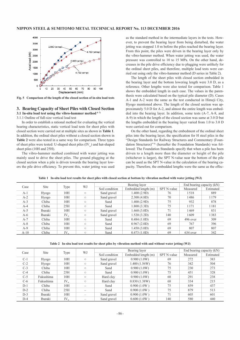
to the bearing layer (GL−17.8 m). The bearing layer was sand with clay. The piles were driven by the vibro-hammer method combined with water jetting. The length (D = 0.484 m) corresponding to the square root of the cross-sectional area was assumed to be the typical pile diameter (D) to the closed cross-sectional area (0.234 m2) of the sheet piles with closed section. The lengths of the closed sections to be driven into the bearing layer were 2.89 D and 4.75 D for compar-ison. Figure 5 shows the relationship of the loads and the amount of settlement between loading at the pile heads and pile bottom (i.e. tip). These results show that when approximately 3.0 D is secured as the length of the closed section, a plugging effect at the bottom (i.e. tip) can be obtained.
Fig. 2 Sheet pile with closed section at bottom
Fig. 3 Comparison of the length of the closed section in chamber tests
Fig. 4 Effect of the length of the closed section on the bearing capacity
NIPPON STEEL & SUMITOMO METAL TECHNICAL REPORT No. 113 DECEMBER 2016
- 86 -
3. Bearing Capacity of Sheet Piles with Closed Section3.1 In-situ load test using the vibro-hammer method 4–7)
3.1.1 Outline of full-size vertical load testIn order to establish a rational method for evaluating the vertical
bearing characteristics, static vertical load tests for sheet piles with closed section were carried out at multiple sites as shown in Table 1. In addition, the ordinal sheet piles without a closed section shown in Table 2 were also tested in a same way for comparison. Three types of sheet piles were tested: U-shaped sheet piles (IVw) and hat-shaped sheet piles (10H and 25H).
The vibro-hammer method combined with water jetting was mainly used to drive the sheet piles. The ground plugging at the closed section when a pile is driven towards the bearing layer low-ers the pile drive efficiency. To prevent this, water jetting was used
as the standard method in the intermediate layers in the tests. How-ever, to prevent the bearing layer from being disturbed, the water jetting was stopped 1.0 m before the piles reached the bearing layer. From this point, the piles were driven in the bearing layer only by the vibro-hammer method. When water jetting was used, the water pressure was controlled to 10 to 15 MPa. On the other hand, de-creases in the pile drive efficiency due to plugging were unlikely for the ordinal sheet piles, and therefore, multiple load tests were car-ried out using only the vibro-hammer method (D series in Table 2).
The length of the sheet piles with closed section embedded in the bearing layer and the bottom lowering length were 3.0 D, as a reference. Other lengths were also tested for comparison. Table 1 shows the embedded length in each case. The values in the paren-thesis were calculated based on the typical pile diameter (D). Cases A-1 and A-2 were the same as the test conducted in Himeji City, Hyogo mentioned above. The length of the closed section was ap-proximately 5.0 D for A-2, and almost the entire length was embed-ded into the bearing layer. In addition, some tests (A-7, A-8, and A-9) in which the length of the closed section was same at 3.0 D but the lengths embedded in the bearing layer varied from 1.0 to 3.0 D were carried out for comparison.
On the other hand, regarding the embedment of the ordinal sheet piles into the bearing layer, the specification for H steel piles in the “Design Standards for Railway Structures and Commentary (Foun-dation Structures)” 8) (hereafter the Foundation Standards) was fol-lowed: The Foundation Standards specify that when a pile has been driven to a length more than the diameter or height of the pile (whichever is larger), the SPT N-value near the bottom of the pile can be used as the SPT N-value in the calculation of the bearing ca-pacity. Therefore, the embedded lengths were the same as the effec-
Fig. 5 Comparison of the length of the closed section of in-situ load tests
Table 1 In-situ load test results for sheet piles with closed section at bottom by vibration method with water jetting (WJ)
Case Site Type WJ Bearing layer End bearing capacity (kN)Soil condition Embedded length (m) SPT N-value Measured Estimated
A-1 Hyogo 10H ○ Sand gravel 1.400 (2.9D) 76 1 518 889A-2 Hyogo 10H ○ Sand gravel 2.300 (4.8D) 70 1 486 1 179A-3 Chiba 10H ○ Sand 1.400 (2.9D) 75 932 878A-4 Chiba 25H ○ Sand 1.800 (3.3D) 75 1 171 1 181A-5 Ibaraki 10H ○ Sand gravel 1.460 (3.0D) 71 1 469 831A-6 Ibaraki IVw ○ Sand gravel 1.520 (3.2D) 140 1 609 1 383A-7 Chiba 10H ○ Sand 0.484 (1.0D) 69 496 over 309A-8 Chiba 10H ○ Sand 0.967 (2.0D) 69 767 396A-9 Chiba 10H ○ Sand 1.450 (3.0D) 69 807 807A-10 Chiba IVw ○ Sand 0.473 (1.0D) 69 634 over 342
Table 2 In-situ load test results for sheet piles by vibration method with and without water jetting (WJ)
Case Site Type WJ Bearing layer End bearing capacity (kN)Soil condition Embedded length (m) SPT N-value Measured Estimated
C-1 Hyogo 10H ○ Sand gravel 0.900 (1.0W) 69 272 383C-2 Hyogo 10H ○ Sand gravel 1.400 (1.56W) 76 342 504C-3 Chiba 10H ○ Sand 0.900 (1.0W) 75 230 273C-4 Chiba 25H ○ Sand 0.900 (1.0W) 75 451 328C-5 Fukushima 10H ○ Hard clay 0.900 (1.0W) 68 291 238C-6 Fukushima IVw ○ Hard clay 0.830 (1.38W) 68 334 215D-1 Chiba 10H – Sand 0.900 (1.0W ) 75 859 437D-2 Chiba 25H – Sand 0.900 (1.0W ) 75 879 513D-3 Ibaraki 10H – Sand gravel 0.900 (1.0W ) 71 605 601D-4 Ibaraki IVw – Sand gravel 0.600 (1.0W ) 140 580 440

NIPPON STEEL & SUMITOMO METAL TECHNICAL REPORT No. 113 DECEMBER 2016
- 87 -
tive diameters of the sheet piles (W), in principle. To make a com-parison based on embedded length, a case (C-2) with a different em-bedded length was also carried out.3.1.2 Load test results
Among the results of the load tests that were carried out in ac-cordance with the Method for Static Axial Compressive Load Tests of Single Piles and the Method for Rapid Load Tests of Single Piles (JGS1812-2002) in the Standards of the Japanese Geotechnical So-ciety, 9) the results focused on the end-bearing capacity are reported below.
The load bearing at the closed section of a sheet pile with closed section was regarded as the end-bearing capacity. Meanwhile, the load bearing at the section of an ordinal sheet pile embedded to the bearing layer was regarded as the end-bearing capacity. Therefore, the total values of frictional resistance in the range for which the end-bearing capacity was evaluated and the resistance at the bottom were used as the end-bearing capacity for both types of sheet piles. In the judgment of the bearing capacity at the bottom of a pile, the load at which displacement at the bottom of the pile reached 10% of the diameter of the pile was determined as the second critical load. As the typical pile diameter (D), the square root of the closed area at the bottom (√A
_) was used on the assumption that the closed cross
section was completely closed at the bottom of a sheet pile with closed section. On the other hand, the typical pile diameter was cal-culated from the square root of the actual cross-sectional area of the sheet pile material (√A
_) on the assumption that no plugging would
be formed on the ordinal sheet piles. Tables 1 and 2 show the end-bearing capacity obtained from the test results. In test cases A-7 and A-10, the loading was ended before the settlement at the bottom of the piles reached 10% of the typical pile diameter due to the tester's capacity, and thus, the specified values are the load values at the end of the tests.
Since multiple tests were carried out at a single site, comparing the results allows the bearing capacity characteristics to be studied. Comparison under the same ground and construction conditions (comparison of A-3 and C-3 and of A-4 and C-4) shows that the use of sheet piles with closed section results in a very large bearing ca-pacity. In addition, comparing the vibro-hammer method with water jetting and the vibro-hammer only method (comparison of C-3 and D-1 and of C-4 and D-2) shows that the bearing capacity tends to decrease when water jetting is used.
Figure 6 shows the relationship between the load and displace-ment at the pile head in the load test carried out in Miho Village in Ibaraki, Japan as a typical case. For the ordinal sheet piles, when the resistance reached the first limit resistance, the load did not increase even when the amount of settlement increased, showing behavior like that of friction piles. On the other hand, for the sheet piles with closed section, as the displacement increased, the load increased. This confirms that sheet piles with closed section have bearing ca-pacity characteristics of the bottom supported type in which plug-ging at the bottom is formed at the closed section.
When focusing on the cases where the embedded lengths of the sheet piles with closed section varied (A-7, A-8, and A-9 in Table 1), the end-bearing capacity values are almost same for A-8 and A-9, and their relationship to the embedded length does not correlate in the same way as that for the estimated values. Because the lengths embedded in the bearing layer did not affect the bearing capacity, plugging in the closed spaces is not necessarily formed in the bear-ing layer but rather during the course of driving. Therefore, if the driving of sheet piles needs to be stopped before the lengths embed-
ded into the bearing layer reach the specified lengths in actual con-struction sites, when an embedded length of around 2.0 D can be se-cured, it is expected that sufficient bearing capacity is generated for sheet piles with closed section.3.2 Bearing capacity evaluation method
This section describes the method used to evaluate the bearing capacity in the design of railway structures. The design vertical force needs to be calculated by multiplying the partial safety factor by the standard bearing capacity value that is equivalent to the char-acteristic value. 7) The characteristic value of the standard bearing capacity is the total of the standard skin-friction capacity and stand-ard end-bearing capacity. This paper mainly handles sheet piles with closed section embedded using the vibro-hammer method with wa-ter jetting, which was used in the load tests. However, useful data could be obtained regarding the bearing capacity of ordinal sheet piles. Therefore, this paper also explains the method for evaluating the end-bearing capacity of ordinal sheet piles using the vibro-ham-mer method with and without water jetting.3.2.1 End-bearing capacity of sheet piles with closed section
The end-bearing capacity of sheet piles with closed section was evaluated based on the formulas specified in the Foundation Stand-ards for the end-bearing capacity of a driven pile with an open bot-tom for which the plugging effect at the bottom fully exists. The formula shown below was used for calculation.
Rp = qpAp = 50 NAp (1)Where Rp is the standard end-bearing capacity of a sheet pile with closed section (kN); qp is the standard end-bearing stress (kN/m2); and Ap is the closed area at the bottom (m2). The end-bearing stress was determined as shown below based on the ground conditions, in particular.
Sandy soil qp = 50 N (≤ 4 000) (2a) Gravel qp = 50 N (≤ 6 000) (2b)The bearing capacity factor of an existing driven pile with an
open bottom (qp) was determined as 150 N. The bearing capacity factor of a sheet pile with closed section is one third of that. When the ground near the bottom of a sheet pile with closed section is strong, the influence of water jetting becomes smaller. In consider-ation of this, the upper limit of the end-bearing stress was deter-mined to be one-half of the upper limit of a driven pile with an open bottom as a result of a comparison and analysis of the estimated val-ues and actual values.3.2.2 End-bearing capacity of ordinal sheet piles
Ordinal sheet piles are handled as piles without plugging at the bottom following the concept for the H steel piles driven by the
Fig. 6 Load displacement curves for bearing capcity

NIPPON STEEL & SUMITOMO METAL TECHNICAL REPORT No. 113 DECEMBER 2016
- 88 -
driving method specified in the Foundation Standards. Therefore, the actual cross-sectional area of the sheet pile was used to calculate the end-bearing capacity. Regarding the evaluation of the end-bear-ing capacity, it was difficult to separate the pure bottom resistance of the actual cross-sectional areas accurately in each load test due to a disturbance in the measurement results of the axial force around the bottom and other factors. Therefore, the end-bearing capacity was defined using the formula below, including skin-friction capacity at the sections embedded in the bearing layer. However, it is neces-sary to note that this point is different from the method used to eval-uate the bearing capacity of sheet piles with closed section.
Rp = qpA´p + ri li U (3)Where A´p is the actual cross-sectional area of the ordinal sheet pile (m2); ri is the skin friction of each soil layer (bearing layer to which the pile is embedded) (kN/m2); l is the length of the section embed-ded in the bearing layer (m); and U is the perimeter of the sheet pile (m).
The formulas below were used to calculate the end-bearing stress (qp) of an ordinal sheet pile. These formulas are the same as those for calculating the end-bearing capacity of an H steel pile specified in the Foundation Standards.
Sandy soil qp = 300 N (≤ 10 000) (4a) Gravel qp = 300 N (≤ 15 000) (4b) Hard cohesive soil and soft rock qp = 100 N (≤ 20 000) (4c)The formulas used to calculate the skin friction in the bearing
layer vary depending on whether water jetting is used in combina-tion with the vibro-hammer method. The formulas below were used to calculate the skin friction when only the vibro-hammer method is used.
Sandy soil ri = 3.0 N (≤ 150) (5a) Gravel ri = 4.0 N (≤ 200) (5b) Hard cohesive soil and soft rock ri = 10 N (≤ 150) (5c) ri = qu/2 (≤ 150) (5d)
Where qu is the unconfined compressive strength of cohesive soil (kN/m2).
To calculate the skin friction of the section embedded in the bearing layer, the formula and upper limit for H steel piles were used. On the other hand, when water jetting was used with the vibro-hammer method, the values and upper limits in the formulas (5a) to (5d) listed above were halved. This is because even if water jetting is stopped before a pile is embedded into the bearing layer, the water discharged up to that point may reach the bearing layer and disturb the ground. The length of the section embedded into the bearing layer for which the skin-friction capacity can be considered should be equal to or less than the effective width of the sheet pile. Even if a large embedded length is secured, it is not taken into account in the calculation of the end-bearing capacity.
Sandy soil ri = 1.5 N (≤ 75) (6a) Gravel ri = 2.0 N (≤ 100) (6b) Cohesive soil ri = 5.0 N (≤ 75) (6c) ri = qu/4 (≤ 75) (6d)
3.2.3 Comparison of the evaluated and actual end-bearing capacityThe formulas mentioned in the previous section were used to
calculate the end-bearing capacity of the piles in the load tests. The calculation results are shown in the rightmost columns in Tables 1 and 2. The tables also show the SPT N-value of the bearing layers used as preconditions for the calculation. However, the evaluation was made without setting upper limits on the SPT N-value. The ta-
ble attached at the end of this paper (Appendix 1) lists the actual cross-sectional areas of the sheet piles, closed cross-sectional areas of the sheet piles with closed section, and typical pile diameters.
Figure 7 shows a comparison of the evaluated and actual end-bearing capacity. The black symbols are the results of the sheet piles with closed section. The white symbols are the results of the ordinal sheet piles. Even though the bearing capacity naturally depends on the ground and construction conditions, the figure shows that the bearing capacity of sheet piles with closed section is approximately double that of ordinal sheet piles. In addition, it also shows that even though there are several differences, such as the type of sheet piles, presence or absence of a closed section, and construction conditions, the proposed formulas can accurately estimate the bearing capacity. The actual bearing capacity values are more than the estimated val-ues in all of the cases for the sheet piles with closed section, in par-ticular, and thus, it can be said the evaluated values are conservative.
These findings have already been incorporated in the Design and Construction Manual for Sheet Pile Foundations Applied to Railway Structures (Version 3), 7) thereby allowing them to be applied to the foundations for railway structures. Refer to the manual for the for-mulas for calculating skin-friction capacity and other information omitted in this paper.
4. Research and Development for Expanding the ApplicationsIn order to establish a method for designing sheet piles with
closed section, the authors have established formulas used to evalu-ate the bearing capacity based on the static load tests carried out in multiple sites using the test piles driven by the vibro-hammer method. However, as of now, these formulas cannot be directly applied to the press-in method or other pile driving method for the design bearing capacity of sheet piles with closed section. Therefore, static load tests were carried out to establish formulas for evaluating the bear-ing capacity of sheet piles with closed section installed by the press-in method. The results are reported below.4.1 In-situ load tests using the press-in method 10)
4.1.1 Outline of full-scale vertical load testsThe sheet piles were installed by the press-in method combined
with water jetting. In the press-in method, unlike the vibro-hammer method, piles cannot be installed to the specified depth without us-ing water jetting as the hardness of the ground increases before the piles reach the bearing layer. In addition, even when water jetting is used, driving the piles is sometimes difficult. Therefore, the tests were carried out on the assumption that water jetting would not be
Fig. 7 Comparison between design capacity and test results

NIPPON STEEL & SUMITOMO METAL TECHNICAL REPORT No. 113 DECEMBER 2016
- 89 -
stopped 1.0 m above the specified depth and the water jetting pres-sure would be kept low for the entire construction length.
Futtsu City in Chiba and Kochi City in Kochi, Japan were se-lected as the load test locations. In the testing ground in Futtsu City, the embedded lengths of the test piles were varied (1.0 D and 3.0 D) to evaluate the influence of the embedded lengths under actual con-struction conditions. In addition to these tests, an additional test was carried out in which the water jetting was stopped 1.0 m above the bearing layer as was the case with the tests using the vibro-hammer method. These piles could only be installed to 0.59 D, but these test piles were subjected to load test as well.
In the testing ground in Kochi City, the locations of the water jetting were compared and studied. Usually, it is desirable to use water jetting both on the closed section and sheet pile sides in con-sideration of the balance as shown in the figure on the right in Fig. 8. However, locating a water jet system on the closed section side poses other problems (such as the routing of the hose). Therefore, other water jetting locations were compared (figure on the left in Fig. 8) mainly to manage construction in the pile driving stage. After start-ing to drive the pile in this test, it was found that the permeability factor of the ground was very high and thus, the water pressure of the water jetting was easily lost. Therefore, it was impossible to drive the pile to a definite bearing layer with an SPT N-value of 50 or more. Consequently, a solid layer consisting of sand and gravel (SPT N-value of 30 or more) specified in the reference 7) was used. The entire length of the closed section (3.0 D) was embedded and the pile driving was stopped at that depth.4.1.2 Vertical load test results
Table 3 shows the press-in test results. Figure 9 shows the rela-tionship between the load at the bottom and displacement at the bot-tom that were made dimensionless with the design bearing capacity of the vibro-hammer method, including consideration whether it could be applied, and the typical pile diameter.
These results show that in the cases in which the embedment was 1.0 D and 3.0 D in the test in Futtsu City (E-1 and E-2), the be-havior was almost the same. In addition, the bearing capacity tended to be slightly smaller than the design bearing capacity. This is proba-bly because of the influence of driving the pile into the bearing layer
using water jetting, although the press-in method's vertical motion may disturb the surrounding ground less than the vibro-hammer method. In the case in which water jetting was stopped 1.0 m above the bearing layer (E-3), even when the length of the section embed-ded into the bearing layer was short at 0.59 D, the bearing capacity was very large. This possibly supports the above supposition. If wa-ter jetting is not used in the bearing layer, the press-in method could provide bearing capacity equal to or more than that of the vibro-hammer method.
The bearing capacity in Case F-1 in Kochi City was almost same as those in Cases E-1 and E-2 in Futtsu City. Meanwhile, in Case F-2 in which the locations of the water jetting were different, a very large bearing capacity was generated. Although it is unclear why the bearing capacity was large in this case, the use of water jetting and the ground mainly consisting of stones with a diameter of 3 to 10 mm may have affected the results. The authors will further study the relationship between the amount of water discharged in water jetting and the ground composition.
5. ConclusionThe sheet piles with closed section introduced in this paper have
been developed to achieve sheet piles with a bearing capacity func-tion. These piles have been studied and developed as materials used to reinforce the foundations of railway structures. The bearing ca-pacity characteristics depending on the pile driving methods of vari-ous types of sheet piles were clarified through full-scale load tests. In addition, the specifications of the closed section and procedures for managing construction in actual sites have also been organized and incorporated into the manual for sheet pile foundations men-tioned above. 7) The authors will carry out further research and de-velopment that will contribute to expanding the applications of the press-in method and other methods and will propose advanced uses for sheet piles.
Table 3 In-situ load test results for sheet piles with closed section at bottom by press-in method
Case Site Type WJ Bearing layer End bearing capacity (kN)Soil condition Embedded length (m) SPT N-value Measured Estimated
E-1 Chiba 10H ○* Sand 0.490 (1.0D) 69 723 807E-2 Chiba 10H ○* Sand 1.460 (3.0D) 69 746 807E-3 Chiba 10H ○ Sand 0.290 (0.59D) 69 1 204 807F-1 Kochi 10H ○* Sand gravel 1.460 (3.0D) 36 385 421F-2 Kochi 10H ○* Sand gravel 1.460 (3.0D) 40 859 421
○*: WJ was used for all driving depth into the bearing layer.
Fig. 8 Test cases in Kochi (comparison of the positions of WJ)
Fig. 9 Load displacement curves driven by press-in method

NIPPON STEEL & SUMITOMO METAL TECHNICAL REPORT No. 113 DECEMBER 2016
- 90 -
AcknowledgmentsIn the development of the sheet pile foundations, the authors
have been working to solve various problems in cooperation with the Japanese Railway Technical Research Institute and Obayashi. We appreciate the enormous assistance received from these parties.
References1) Japanese Railway Technical Research Institute: Design and Construction
Manual for Sheet Pile Foundations Applied to Railway Structures. Ver-sion 1. 2005
2) Taenaka, S. et al.: Characterization of Vertical Bearing Capacity of Sheet-Piles. Journal of the Japan Society of Civil Engineers, Division C. 63 (1), 285–298, (2007)
3) Nakayama, H. et al.: Evaluation of the Bearing Capacity Characteristics of Steel Sheet Piles with Closed Section at the Bottom. 66th Annual Meeting of the Japan Society of Civil Engineers. Matsuyama, III-219, September 2011
4) Kato, A. et al.: Evaluation of Vertical Bearing Capacity of Sheet Piles by Static Loading Tests. 55th Geotechnical Engineering Symposium. To-kyo, November 2010
5) Nakayama, H. et al.: Static Vertical Load Tests for Steel Sheet Piles with Closed Section at the Bottom. 56th Geotechnical Engineering Sympo-sium. Tokyo, November 2011
6) Nakayama, H. et al.: Static Load Tests on Vertical Bearing Capacity of Steel Sheet Piles with Closed Sections. 9th Int. Conf. on Testing and De-sign Methods for Deep Foundations. Kanazawa, Japan, September 2012
7) Japanese Railway Technical Research Institute, Obayashi Corporation, and Nippon Steel & Sumitomo Metal Corporation: Design and Con-struction Manual for Sheet Pile Foundations Applied to Railway Struc-
tures (draft). Version 3. 20148) Japanese Ministry of Land, Infrastructure, Transport, and Tourism (su-
pervisor) and Japanese Railway Technical Research Institute (Editor): Design Standards for Railway Structures and Commentary (Foundation Structures and Earth Structures). Maruzen, June 2000
9) Japanese Geotechnical Society: Standard for Vertical Load Tests of Piles. 2002
10) Nakayama, H. et al.: Static Load Tests on Vertical Bearing Capacity of Steel Sheet Piles with Closed Sections Driven by Press-in Method. 49th Conference of the Japanese Geotechnical Society. Kitakyushu, July 2014
Appendix 1 Tip area of end bearing capacity and the diameter
TypeSheet pile
Sheet pile with closed section at bottom
A (m2) D (m) A (m2) D (m)10H 0.01100 0.1049 0.234 0.483725H 0.01444 0.1202 0.300 0.547745H 0.03500 0.1871 0.370 0.608350H 0.03990 0.1997 0.372 0.6105IIw 0.00787 0.0887 0.154 0.3924IIIw 0.01039 0.1019 0.202 0.4494IVw 0.01353 0.1163 0.225 0.4743VL 0.01338 0.1157 0.177 0.4207VIL 0.0153 0.1237 0.191 0.4370
Shinji TAENAKASenior Researcher, Ph.D.Steel Structures Research Lab.Steel Research Laboratories20-1 Shintomi, Futtsu City, Chiba Pref. 293-8511
Kazutaka OTSUSHISenior Manager, Dr.Eng.Foundation Products Engineering Dept.-IIConstruction Products Development Div.Construction Products Unit
Atsushi KATOResearcherSteel Structures Research Lab.Steel Research Laboratories
Hiroaki NAKAYAMASenior Researcher, Ph.D.Steel Structures Research Lab.Steel Research Laboratories
Kazuhide TODAFoundation Products Engineering Dept.-IIConstruction Products Development Div.Construction Products Unit
Ryuta TANAKAManagerFoundation Products Engineering Dept.-IIConstruction Products Development Div.Construction Products Unit
Noriyoshi HARATASenior Manager, Head of Dept.Foundation Products Engineering Dept.-IIConstruction Products Development Div.Construction Products Unit