Embed Size (px)
Citation preview
NIPPON STEEL & SUMITOMO METAL TECHNICAL REPORT No. 113 DECEMBER 2016
- 133 -
1. IntroductionWith the growth of developing countries, demand for energy and
infrastructures continues to expand and such demand for construc-tion is expected to increase hereafter as well. To date, Nippon Steel & Sumitomo Metal Corporation has continued to tackle the devel-opment of the overseas steel construction market mainly based on ODA related projects. In 2011, the company built a steel pipe mill, NPV (Nippon Steel & Sumikin Pipe Vietnam), in Phu My in South Vietnam and has established a stabilized overseas supply system.
Nippon Steel & Sumitomo Metal is currently promoting the market development of the demand for high-end products selective-ly based on utilization of its technologies, the products of which are competitive overseas. This article reports the approach to the devel-opment of the overseas market so far and the actual results obtained thereby as to (1) Hat + H piles, (2) Sheet pile cells and the (3) Sat-in pile foundation construction method, using the high-suitability prod-ucts of Nippon Steel & Sumitomo Metal, namely Hat-type steel sheet piles, flat steel sheet piles and, steel pipe piles with internal ribs.
2. Hat + H Piles 1, 2)
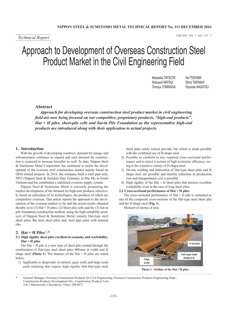
2.1 High rigidity sheet piles excellent in economy and workability: Hat + H pilesThe Hat + H pile is a new type of sheet pile created through the
combination of Hat-type steel sheet piles 900 mm in width and H shape steel (Photo 1). The features of the Hat + H piles are stated below.
1) Applicable to deepwater revetment, quay walls and large-scale earth retaining that require high rigidity that Hat-type steel
sheet piles solely cannot provide, but which is made possible with the combined use of H shape steel.
2) Possible to conform to any required cross-sectional perfor-mance and to select a section of high economic efficiency ow-ing to the extensive variety of H shape steel.
3) On-site welding and fabrication of Hat-type sheet piles and H shape steel are possible and thereby reduction in production cost and transportation cost is possible.
4) High rigidity of the Hat + H sheet piles that possess excellent workability even in the case of long sheet piles.
2.2 Cross-sectional performance of Hat + H pilesThe cross-sectional performance of Hat + H pile is estimated as
one of the composite cross-sections of the Hat-type steel sheet pile and the H shape steel (Fig. 1).
Moment of inertia of area:
Technical Report UDC 624 . 154 . 7 : 624 . 157 . 7
* General Manager, Overseas Construction Products for Civil Engineering, Overseas Construction Products Engineering Dept., Construction Products Development Div., Construction Products Unit
2-6-1 Marunouchi, Chiyoda-ku, Tokyo 100-8071
Approach to Development of Overseas Construction Steel Product Market in the Civil Engineering Field
Masataka TATSUTA* Kei TESHIMANobuyuki MATSUI Shinji TAENAKATomoya TOMINAGA Ryosuke NAGATSU
AbstractApproach for developing overseas construction steel product market in civil engineering
field are now being focused on our competitive, proprietary products, “high-end products”. Hat + H piles, sheet-pile cells and Sat-in Pile Foundation as the representative high-end products are introduced along with their application to actual projects.
Photo 1 Outline of the Hat + H piles

NIPPON STEEL & SUMITOMO METAL TECHNICAL REPORT No. 113 DECEMBER 2016
- 134 -
I = IS + As · yS2 + IH + AH · yH
2
where I : Moment of inertia of area of a Hat + H pileIS : Moment of inertia of area of a Hat-type steel sheet pileAs : Cross-sectional area of a Hat-type steel sheet pileIH : Moment of inertia of area of a H shape steelAH : Cross-sectional area of an H shape steelyS : Distance between the center of gravity of the Hat-type steel
sheet pile and the neutral axis of the Hat + H pileyH : Distance between the center of gravity of the H shape steel
and the neutral axis of the Hat + H pileTable 1 shows an example of the cross-sectional performance of
Hat + H piles. A Hat-type steel sheet pile and an H shape steel are fabricated by intermittent fillet welding. The fillet welding leg size and the welding length are determined by the combination of the Hat-type steel sheet pile and the H shape steel used; however, gener-ally the integration of the sections is secured with a fillet welding leg size of 6–8 mm and a welding length of 40–60% over the entire length. (1) Actual size flexural test of Hat + H piles
In order to confirm the cross-sectional performance of Hat + H piles, an actual size flexural test was conducted. The outline of the experiment is shown in Fig. 2 and Table 2. In Fig. 3, the relation-ship between the bending moment and the curvature obtained from the result of the test is shown. The figure shows that the experimen-tal values agree with the calculated values up to the yielding strength level. Accordingly, it was confirmed that a Hat + H pile can be eval-uated as a composite cross-section.2.3 Fabrication of Hat + H piles
A Hat-type steel sheet pile and an H-shape steel are fabricated to a single pile with intermittent fillet welding. Therefore, correction
work is not required and the welding operation can be rendered suf-ficiently at the construction site, not necessarily in a fabrication shop. Furthermore, as shown in Photo 2, welding operation can be rendered at two locations simultaneously which serves the purpose of preventing the torsional deformation of the entire pile. The fabri-cation work in a yard near a construction site reduces the labor of transportation and storage greatly.2.4 Execution of Hat + H pile construction(1) Construction execution method
Construction of Hat + H pile is possible with conventional ma-
Fig. 1 Calculation of Hat + H piles
Table 1 Example of the cross section and property of Hat + H piles
Cross section(unit: mm)
10H + H750 × 250 × 12 × 19
Weight (kg/m) 256Section modulus Z (cm3/m) 6 770Moment of inertia I (cm4/m) 379 000
Fig. 2 Outline of the flexural test
Table 2 Specimens and sectional properties
Sheet PileH shape
(H × B × tw × tf)(mm)
Sectional properties (per 1 m length)
Weight(kg/m)
Moment of inertia
(cm4/m)
Section modulus(cm3/m)
10H 400 × 200 × 9 × 12 169 88 074 2 320H: Depth of section, B: Width of section, tw: Web thicknesstf : Flange thickness
Fig. 3 Bending moment to curvature
Photo 2 Fabrication on site
NIPPON STEEL & SUMITOMO METAL TECHNICAL REPORT No. 113 DECEMBER 2016
- 135 -
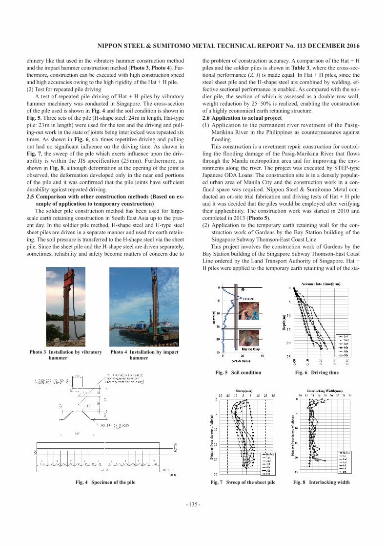
chinery like that used in the vibratory hammer construction method and the impact hammer construction method (Photo 3, Photo 4). Fur-thermore, construction can be executed with high construction speed and high accuracies owing to the high rigidity of the Hat + H pile.(2) Test for repeated pile driving
A test of repeated pile driving of Hat + H piles by vibratory hammer machinery was conducted in Singapore. The cross-section of the pile used is shown in Fig. 4 and the soil condition is shown in Fig. 5. Three sets of the pile (H-shape steel: 24 m in length, Hat-type pile: 23 m in length) were used for the test and the driving and pull-ing-out work in the state of joints being interlocked was repeated six times. As shown in Fig. 6, six times repetitive driving and pulling out had no significant influence on the driving time. As shown in Fig. 7, the sweep of the pile which exerts influence upon the driv-ability is within the JIS specification (25 mm). Furthermore, as shown in Fig. 8, although deformation at the opening of the joint is observed, the deformation developed only in the near end portions of the pile and it was confirmed that the pile joints have sufficient durability against repeated driving. 2.5 Comparison with other construction methods (Based on ex-
ample of application to temporary construction)The soldier pile construction method has been used for large-
scale earth retaining construction in South East Asia up to the pres-ent day. In the soldier pile method, H-shape steel and U-type steel sheet piles are driven in a separate manner and used for earth retain-ing. The soil pressure is transferred to the H-shape steel via the sheet pile. Since the sheet pile and the H-shape steel are driven separately, sometimes, reliability and safety become matters of concern due to
the problem of construction accuracy. A comparison of the Hat + H piles and the soldier piles is shown in Table 3, where the cross-sec-tional performance (Z, I) is made equal. In Hat + H piles, since the steel sheet pile and the H-shape steel are combined by welding, ef-fective sectional performance is enabled. As compared with the sol-dier pile, the section of which is assessed as a double row wall, weight reduction by 25–50% is realized, enabling the construction of a highly economical earth retaining structure. 2.6 Application to actual project(1) Application to the permanent river revetment of the Pasig-
Marikina River in the Philippines as countermeasures against floodingThis construction is a revetment repair construction for control-
ling the flooding damage of the Pasig-Marikina River that flows through the Manila metropolitan area and for improving the envi-ronments along the river. The project was executed by STEP-type Japanese ODA Loans. The construction site is in a densely populat-ed urban area of Manila City and the construction work in a con-fined space was required. Nippon Steel & Sumitomo Metal con-ducted an on-site trial fabrication and driving tests of Hat + H pile and it was decided that the piles would be employed after verifying their applicability. The construction work was started in 2010 and completed in 2013 (Photo 5). (2) Application to the temporary earth retaining wall for the con-
struction work of Gardens by the Bay Station building of the Singapore Subway Thomson-East Coast LineThis project involves the construction work of Gardens by the
Bay Station building of the Singapore Subway Thomson-East Coast Line ordered by the Land Transport Authority of Singapore. Hat + H piles were applied to the temporary earth retaining wall of the sta-
Fig. 4 Specimen of the pile
Photo 3 Installation by vibratory hammer
Photo 4 Installation by impact hammer
Fig. 5 Soil condition Fig. 6 Driving time
Fig. 7 Sweep of the sheet pile Fig. 8 Interlocking width

NIPPON STEEL & SUMITOMO METAL TECHNICAL REPORT No. 113 DECEMBER 2016
- 136 -
tion building construction. In the construction work, the Hat + H piles were employed owing to their highly appraised high rigidity, efficient cross-sectional performance, nearness of the fabrication work site to the construction site and excellent drivability (Photo 6, Photo 7). 2.7 Evolution in future
As described above, the Hat + H pile construction method is re-liable from the structural viewpoint and furthermore, excellent in economy and drivability; the repeated use of piles for temporary earth retaining is possible. Furthermore, actual overseas experience has been steadily accumulated and Nippon Steel & Sumitomo Metal will push forward the overseas application of the pile with high ri-gidity to revetment, quay walls and large-scale temporary earth re-taining construction.
3. Flat Steel Sheet Pile Cell Construction Method3.1 Flat steel sheet pile cell construction method suited to revet-
ment of reclaimed land and quay wallsThe production of the flat steel sheet piles used for the steel
sheet pile cell construction method was started in 1953 in this coun-try and the sheet piles have been applied to a number of harbor and port facilities and artificial island construction projects such as the Kisarazu artificial island of the Tokyo Bay highway. The steel sheet pile cell construction method is used, as shown in Fig. 9, to con-struct a structure that consists of cylindrically assembled flat steel sheet piles and filled in with sand to withstand external forces. The steel sheet pile cell structure has the following features: high con-struction speed, possible penetration to ground and reduced ground improvement thereby, high stability in construction work after the completion of filling in with sand, reduced amount of steel and high economic efficiency and the applicability to the revetment of re-claimed land and quay walls is high. The flat type steel sheet piles of NSSMC have the following features:
1) High interlocking tensile strength of joints: 5.88 MN/m or higher of NS-SP-FXL
2) High freedom of angular movement of joints in interlocking state: 10 degrees or higher
Photo 5 Application to river revetment in Philippines (during construction)
Photo 6 Installation of Hat + H at MRT Project in Singapore
Photo 7 Installed Hat + H at MRT Project in Singapore
Fig. 9 Outline of steel sheet pile cell method
Table 3 Comparison study with the soldier pile system
TypeSoldier pile Hat + H
Built-up section Composite section
Outline
Section
H-shape: UB610 × 229 × 243 (mm)U-type steel sheet pile FSP-IVSection modulus Z = 6 264 cm3/mMoment of inertia I = 168 000 cm4/m
Equivalent Z = 6 770 cm3/m10H + HY750 × 250 × 12 × 19 (mm)Equivalent I = 171 000 cm4/m10H + HY700 × 250 × 12 × 19 (mm)
Comparison

NIPPON STEEL & SUMITOMO METAL TECHNICAL REPORT No. 113 DECEMBER 2016
- 137 -
3) The maximum length of the product: 38 mWith these features, the applicable water depth of the cell struc-
ture is increased and workability is enhanced. 3.2 Application to revetment of artificial island of Hong Kong
Hong Kong/Zhuhai/Macau Long BridgeThis project is a part of the large construction project of a high-
way of about 40 km connecting Hong Kong and Macau, and in-volves construction of a Hong Kong artificial island on the east side of Hong Kong International Airport planned for the installation of Hong Kong Boundary Crossing Facilities on the Hong Kong side territory (HKBCF). In the project, the steel sheet pile cell construc-tion method was finally employed based on the following grounds that the construction method is: 1) environment-friendly and appro-priate for a construction site inhabited by an endangered animal (white dolphin), 2) able to solve the aeronautical height limitation and, 3) highly appreciated for the integrated system of NSSMC in manufacturing, designing, execution of construction and delivery, verified by numerous domestic and overseas project experiences.
1) For the protection of the endangered animal, the impact ham-mer construction method and the use of a water jet are prohib-ited, but the steel sheet pile cell construction method can be executed by vibratory hammer machinery alone.
2) This construction site is adjacent to Hong Kong International Airport and the aeronautical height limitation has to be strictly observed even during the construction period. To comply with the limitation, installation barges for exclusive use were built (Photo 8).
3) In the construction, 85 steel sheet pile cells 26.9 m and 31.194 m in diameter with a length of 23.6 m–37.1 m were used. A semi-prefabrication method was employed in which a quarter of a cell was fabricated on land, transported to the site by a barge of exclusive use and fabricated to a complete cell on-site (Photo 9). The construction of the steel pipe pile cell was started in 2012 and the construction of the steel sheet pile cells was com-pleted in 2014 (Photo 10).
Henceforth based on this result, Nippon Steel & Sumitomo Metal is determined to further promote the application of the construction method to the revetment of large-scale reclamation constructions for airports, industrial waste disposal sites, highways and so forth not only in Hong Kong, but also in other overseas countries.
4. Sat-in Pile Foundation4.1 Steel pipe pile foundation construction method to realize on-
site labor reductionEncouraged by the brisk investment in resources and energy, ex-
ploration of such is spreading worldwide. In a company with such movements, exploration in remote areas where active developments have not been conducted so far and the construction of nearby relat-ed land plants are in progress. In these areas, arrangements of site workers are difficult and although the situation depends on coun-tries, there are problems of harsh climates, safety, escalating labor cost and stringent environmental regulations and therefore the need for on-site labor reduction is high.
As shown in Fig. 10, the Sat-in pile foundation is the one-col-umn in one-pile system in which the column of the upper structure is directly inserted into the inside of a relatively large pipe pile and connected thereto. It is a foundation type developed for iron and steel plants as one of the methods for labor-saving in foundation construction and shortening of the construction period. Domestically, the certification by the Building Center of Japan (a general incorpo-
rated foundation) was obtained in 2003 (No. BCJ Rating-FD0061-01) 3) and the actual application results of more than 20 mainly plant foundations have been achieved. When compared with
Photo 8 Installation barges for limited height for construction
Photo 9 Delivery the fabricated quarter cells
Photo 10 Installation of steel sheet pile cell at HKCBF in Hong Kong
Fig. 10 Sat-in pile foundation

NIPPON STEEL & SUMITOMO METAL TECHNICAL REPORT No. 113 DECEMBER 2016
- 138 -
the conventional concrete footing foundation, reduction in the amounts of earthwork and concrete work, both of which are labor incentive work, is possible and as shown in Fig. 11, the total cost of the foundation work can be reduced by about 20–30% and shorten-ing of the construction period by about 30–40% is possible. Further-more, as compared with the concrete footing foundation, the area occupancy ratio is low and the freedom of work of land-buried pip-ing and wiring that is indispensable to plant construction can also be enhanced. 4.2 Outline of structure of Sat-in pile foundation and load transfer
The Sat-in pile foundation is a joining method of a column and a foundation steel pipe pile in which the inside of the steel pipe pile is filled in with concrete after the column is inserted into the steel pipe pile through its head. For the pipe pile, internally ribbed pipe piles (projection) (JIS A 5525) 4) are used in order to secure the transfer of the load from the upper structure via the filled-in concrete. As Photo 11 shows, a rolled steel strip sheet with projections of a height of 2.5 mm or higher that are arranged at a spacing distance of 40 mm or less is formed on a pipe by the spiral pipe forming method so that the projections are formed spirally on the inside of the pipe. There are no restrictions on the installation method of the steel pipe pile and the method is applicable to the impact hammer driving method, inner excavation method, rotational pile penetration method and so forth.
Among the loads exerted by the upper structure, the axial load is transferred to the lower filled-in concrete as the bearing pressure of the base plate installed at the bottom of the inner column and the filled-in concrete supports the bearing pressure, being supported by the internal projections of the outer steel pipe. On the other hand, the acting bending moment and the horizontal shearing load are transferred to the upper filled-in concrete as a form of bearing pres-sure of mainly the side surface of the column and to the outer steel pipe, where it is transformed to a hoop tension and supported (Fig. 12). 4.3 Application of Sat-in pile foundation to foundation of over-
seas plant(1) Problem in application
Although the Sat-in pile foundation is a construction method that has already obtained the certification of the Building Center of Ja-pan and has actual records of application, for the application to the foundations of overseas land plants, the following problems exist.
1) Design method: Application to limit state design method (LRFD)
2) Structural scale: Application to piles 1200 mm or larger in di-ameter
3) Certification: Acquisition of international certification issued by an overseas third party organization
Then, in order to obtain the technical qualification 5, 6) of the structure and design method of DNV (Det Norske Veritas; Current DNV-GL), an organization rich in actual results of granting techni-cal qualifications in design standard and approval of projects of a number of jacket foundations and monopile type foundation struc-tures of the latest offshore wind turbines, a study on the respective technical problems to solve the abovementioned issues was execut-ed.
Domestically, since the design method based on the allowable stress has already been established, the transition to the limit state design method is achieved by rearranging the possible fracture mode and by transferring it to the formulae that conforms to the limit state design method.
Among the technical problems, correspondence to the pipe pile 1 200 mm or larger in diameter was required to expand the area of application (structure scale). Particularly, the assessment of the bond strength of the steel pipe with internal projections that governs the transfer of the axial load is important. In the domestic assessment, the adhesion strength of the steel pipe with internal projections is determined by whichever is smaller of the calculated values of the strength of the projection against the bearing pressure or the sharing strength of the concrete generated between the two adjacent projec-tions but, the specification of the steel pipe such as diameter and wall thickness is not taken into consideration when calculating the strength. However, the internal adhesion property of the projected steel pipe is dependent on the restraining effect of a steel pipe 7) and is strongly affected by mainly the diameter vs. wall thickness ratio of the steel pipe. Accordingly, it is difficult to apply the conventional adhesion strength calculation method to expanded steel pipe piles and review of the calculation method was required.
Fig. 11 Estimation of cost reduction
Photo 11 Steel pipe with ribs and the detail
Fig. 12 Load transfer in Sat-in pile foundation
NIPPON STEEL & SUMITOMO METAL TECHNICAL REPORT No. 113 DECEMBER 2016
- 139 -
(2) Revision of assessment method of adhesion property 8)
Upon revising the adhesion property, collection and analysis of the already existing data used for applications for assessment were conducted and an additional test was performed. The data thus ob-tained cover almost the entire area of practical construction of a di-ameter vs. wall thickness ratio of 38–67 (D/t; D is the pile diameter, t is the wall thickness.), concrete strength (Fcu) of 25–50 N/mm2 and a shear key ratio of 0.06–0.12 (h/s; h is the projection height, s is the projection spacing).
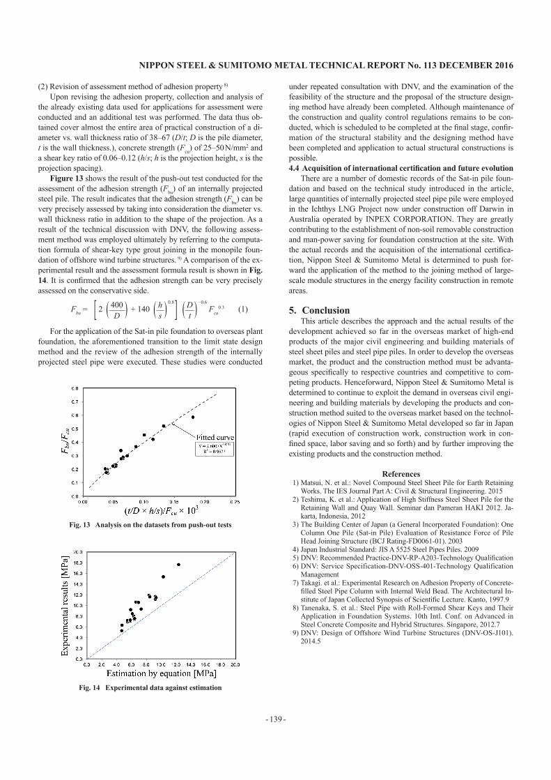
Figure 13 shows the result of the push-out test conducted for the assessment of the adhesion strength (Fbu) of an internally projected steel pile. The result indicates that the adhesion strength (Fbu) can be very precisely assessed by taking into consideration the diameter vs. wall thickness ratio in addition to the shape of the projection. As a result of the technical discussion with DNV, the following assess-ment method was employed ultimately by referring to the computa-tion formula of shear-key type grout joining in the monopile foun-dation of offshore wind turbine structures. 9) A comparison of the ex-perimental result and the assessment formula result is shown in Fig. 14. It is confirmed that the adhesion strength can be very precisely assessed on the conservative side.
Fbu = [ 2 ( 400 ) + 140 ( h ) 0.8] ( D ) −0.6
Fcu0.3 (1)
D s t
For the application of the Sat-in pile foundation to overseas plant foundation, the aforementioned transition to the limit state design method and the review of the adhesion strength of the internally projected steel pipe were executed. These studies were conducted
under repeated consultation with DNV, and the examination of the feasibility of the structure and the proposal of the structure design-ing method have already been completed. Although maintenance of the construction and quality control regulations remains to be con-ducted, which is scheduled to be completed at the final stage, confir-mation of the structural stability and the designing method have been completed and application to actual structural constructions is possible. 4.4 Acquisition of international certification and future evolution
There are a number of domestic records of the Sat-in pile foun-dation and based on the technical study introduced in the article, large quantities of internally projected steel pipe pile were employed in the Ichthys LNG Project now under construction off Darwin in Australia operated by INPEX CORPORATION. They are greatly contributing to the establishment of non-soil removable construction and man-power saving for foundation construction at the site. With the actual records and the acquisition of the international certifica-tion, Nippon Steel & Sumitomo Metal is determined to push for-ward the application of the method to the joining method of large-scale module structures in the energy facility construction in remote areas.
5. ConclusionThis article describes the approach and the actual results of the
development achieved so far in the overseas market of high-end products of the major civil engineering and building materials of steel sheet piles and steel pipe piles. In order to develop the overseas market, the product and the construction method must be advanta-geous specifically to respective countries and competitive to com-peting products. Henceforward, Nippon Steel & Sumitomo Metal is determined to continue to exploit the demand in overseas civil engi-neering and building materials by developing the products and con-struction method suited to the overseas market based on the technol-ogies of Nippon Steel & Sumitomo Metal developed so far in Japan (rapid execution of construction work, construction work in con-fined space, labor saving and so forth) and by further improving the existing products and the construction method.
References1) Matsui, N. et al.: Novel Compound Steel Sheet Pile for Earth Retaining
Works. The IES Journal Part A: Civil & Structural Engineering. 20152) Teshima, K. et al.: Application of High Stiffness Steel Sheet Pile for the
Retaining Wall and Quay Wall. Seminar dan Pameran HAKI 2012. Ja-karta, Indonesia, 2012
3) The Building Center of Japan (a General Incorporated Foundation): One Column One Pile (Sat-in Pile) Evaluation of Resistance Force of Pile Head Joining Structure (BCJ Rating-FD0061-01). 2003
4) Japan Industrial Standard: JIS A 5525 Steel Pipes Piles. 20095) DNV: Recommended Practice-DNV-RP-A203-Technology Qualification6) DNV: Service Specification-DNV-OSS-401-Technology Qualification
Management7) Takagi. et al.: Experimental Research on Adhesion Property of Concrete-
filled Steel Pipe Column with Internal Weld Bead. The Architectural In-stitute of Japan Collected Synopsis of Scientific Lecture. Kanto, 1997.9
8) Tanenaka, S. et al.: Steel Pipe with Roll-Formed Shear Keys and Their Application in Foundation Systems. 10th Intl. Conf. on Advanced in Steel Concrete Composite and Hybrid Structures. Singapore, 2012.7
9) DNV: Design of Offshore Wind Turbine Structures (DNV-OS-J101). 2014.5
Fig. 13 Analysis on the datasets from push-out tests
Fig. 14 Experimental data against estimation
NIPPON STEEL & SUMITOMO METAL TECHNICAL REPORT No. 113 DECEMBER 2016
- 140 -
Masataka TATSUTAGeneral Manager, Overseas Construction Products for Civil EngineeringOverseas Construction Products Engineering Dept.Construction Products Development Div.Construction Products Unit2-6-1 Marunouchi, Chiyoda-ku, Tokyo 100-8071
Shinji TAENAKASenior Researcher, Ph.D.Steel Structures Research Lab.Steel Research Laboratories
Kei TESHIMASenior ManagerNIPPON STEEL & SUMITOMO METAL Southeast Asia Pte. Ltd.
Tomoya TOMINAGASenior ManagerOverseas Construction Products Engineering Dept.Construction Products Development Div.Construction Products Unit
Nobuyuki MATSUIManagerNIPPON STEEL & SUMITOMO METAL Southeast Asia Pte. Ltd.
Ryosuke NAGATSUManagerShanghai OfficeNIPPON STEEL & SUMITOMO METAL Consulting (Beijing) Co., Ltd.