Embed Size (px)
Citation preview

S t r u c t u r a l O p t i o n
P r o f e s s o r B e h r
H o s p i t a l P a t i e n t T o w e r
E a s t C o a s t U . S . A .
1 0 / 4 / 2 0 1 0
Matthew R Peyton
This Document is Technical Report #1 for 5th year senior
thesis in the Architectural Engineering Departments at The
Pennsylvania State University. This Report will include
structural concepts and structural existing conditions for
the Hospital Patient Tower.
Technical Report #1

Technical Report #1
Structural Concepts/Existing Conditions
Matthew R Peyton
Page 1 of 44
Table of Contents Executive Summary ....................................................................................................................................... 2
Introduction .................................................................................................................................................. 3
Structural Systems ........................................................................................................................................ 4
Foundations .............................................................................................................................................. 4
Columns .................................................................................................................................................... 4
Floor System ............................................................................................................................................. 5
Roof System .............................................................................................................................................. 5
Lateral System ........................................................................................................................................... 6
Design & Code Review .................................................................................................................................. 7
Design Codes and References ................................................................................................................... 7
Thesis Codes and References .................................................................................................................... 7
Deflection Criteria ..................................................................................................................................... 7
Floor Deflection Criteria ........................................................................................................................ 7
Material Specifications.............................................................................................................................. 8
Gravity Loads................................................................................................................................................. 9
Dead Loads ................................................................................................................................................ 9
Live Loads .................................................................................................................................................. 9
Snow Loads ............................................................................................................................................... 9
Lateral Loads ............................................................................................................................................... 10
Wind Loads .............................................................................................................................................. 10
Seismic Loads .......................................................................................................................................... 11
Spot Checks ................................................................................................................................................. 12
Gravity Column Spot Check .................................................................................................................... 12
Drop Panels/Punching Shear Spot Check................................................................................................ 12
Slab Spot Check ....................................................................................................................................... 12
Conclusion ................................................................................................................................................... 13
Appendix I ................................................................................................................................................... 14
Appendix II .................................................................................................................................................. 19
Appendix III ................................................................................................................................................. 31
Appendix IIII ................................................................................................................................................ 38

Technical Report #1
Structural Concepts/Existing Conditions
Matthew R Peyton
Page 2 of 44
Executive Summary Technical Report #1 is a structural systems and existing conditions analysis of the Patient Tower as an
expansion of an existing patient tower. This report includes research about the structural system and
the process of design. All of the calculations preformed were done in compliance with the most up to
date codes for structural design.
This 12 story Patient tower is an expansion to an existing patient tower as an early stage of a large
capital expansion plan. This tower utilizes piles and grade beams as a foundation with a concrete
structural system. Typical Column size 24” x 24” they have varying rebar placement and design of both
vertical and horizontal. Since the Patient Tower needs to line up with the existing structure the floor to
floor high was a large consideration in the structural design. Patient Tower has a few design features to
make it acceptable to another expansion to be started soon.
The Wind and Seismic loads were both calculated using AISC 7-10. After the calculations of these two loads it was determined that the wind controls in the East-West Direction and Seismic controls in the North-South direction.
For the Stop Checks of the tower three different elements form the towers structure were analyzed and
compared to the design that was done by the structural engineer. The gravity load check of an interior
column determined that the column was oversized but it was assumed that there were no lateral forces
involved. A check of the drop panels was also performed against the punching shear in the slab. A check
of the slab system was the third and last spot check of Tech Report #1.

Technical Report #1
Structural Concepts/Existing Conditions
Matthew R Peyton
Page 3 of 44
Introduction The Patient Tower is part of the 2015 Capital Improvement Project, of which the Tower Expansion is one
of the earlier phases. The new Patient Tower will connect with an existing patient tower by a bank of
elevators separated into two sections one for visitors and the other for patients at every floor. The
Tower will also await the connection of a women health facility that is one of the next phases of the
Capital Improvement Project. The Façade of the Patient Tower will blend in with the existing buildings
by keeping some of the red brick on the exterior but also taking on a more modern look by incorporating
aluminum curtain wall and precast concrete panels. The new Tower consists of 12 stories above grade
with one level below grade. The Tower is 216,000 Square feet with 174 patient rooms, an operation
facilities and a mechanical level. The Contract for this tower was awarded to Turner Construction, the
general contractor in a Design-Bid-Build method with a contact value of $161 million.
One of the main design considerations is individual patient rooms. Based on the Hospitals goals for care
the individual patient rooms were a large factor in the design of the floor plan. During the design phases
the project team requested input for the Physician, nurses and staff to help make the design as efficient
as possible. Medical/surgical patients aging 65years and older were the focus of this Tower with a
special emphasis on their safety and a good healing environment. With the Hospital team input the
placement for monitoring stations were optimized to ensure patient privacy as well as enhancing the
monitoring capabilities.
One of the hospitals goals as well as patient care is as so to lower their impact on the environment. The
hospitals plan for this new tower included green features such as living roofs low flow water fixtures and
rain gardens. The design also calls for no/low VOC building materials to be used in construction of the
Tower. The Tower design has been submitted for a LEED Silver certification.
Figure 1: Sketch by Wilmot Sanz

Technical Report #1
Structural Concepts/Existing Conditions
Matthew R Peyton
Page 4 of 44
Structural Systems
Foundations The geotechnical report was prepared by Schnabel Engineering, LLC, on March 25, 2010. The
Foundations of the patient tower is set on piles, with pile caps and grade beams. Each column location
has a range from 4 to 12 piles. The slab on grade for the tower is 5” with integrated slab pile caps in
locations of high stress such as the elevator shaft and stair well. During the excavation for the new
tower the existing basement and caissons supporting the connecting structure were exposed. The
existing 66” caissons will support a small portion of the tower connection while the rest will be
supported by new piles. In a few locations where there is no basement level piles were drilled to reach
up to the ground floor level to support irregular building features.
Columns The column layout of the patient tower is very
regular with a few variations on the 1st through 3rd
floors. The bay spacing in the patient tower is mostly
square 29’ x 29’ with a few exceptions as see in
Figure 3 to the right. The columns are reinforced
concrete ranging in size from 30” x 30” to 12” x 18”.
The main column size is 24” x 24” with vertical
reinforcing of #11 bars numbering from 12 to 4 as
they move up the structure. The vertical reinforcing
is tied together with #4 bars placed every 18”. The
columns on the basement level up through the 4th
floor are poured with 7,000 psi concrete and from
the 5th floor up they are 5,000 psi concrete.
The structural system of the Patient Tower utilizes column capitals to resist punching shear with in the slab. The typical capital in the tower is 10’ x 10’ x 6” depth, making the slab thickness at the capitals 15 ½”.
Figure 1: Tower Sketch by Wilmot Sanz
Figure 3: Typical Column layout
Figure 2: Column reinforcing detail

Technical Report #1
Structural Concepts/Existing Conditions
Matthew R Peyton
Page 5 of 44
Floor System The Floor system for this patient tower is a 9 ½” 2-way flat plate. For the ground floor through the 4th
floor the slab is 5000 psi concrete with the remaining floors at 4000 psi concrete. The larges span for this
flat plan is 29’ in each direction with square bays. The flat plate system has both top and bottom steel
reinforcing. The top steel placed at places of negative moment is typical notated with a number of #5
bars. The bottom reinforcing is a 2-way mat of #5 bars at 12” on center. In the end bays of the slab there
is extra bottom bars added to handle the carry over moments for the interior span. On the 5th floor of
the tower is the mechanical level which increases the loading on the slab giving it a 10 ½” concrete slab.
See figure 4 below for details.
Roof System The roof system for the patient tower is designed with the same conditions at a typical floor, a 9 ½” 2-
way flat plate with mat and bar reinforcing detailed in the above section. The roof does have a few
variations from a typical floor; the roof area that will support the
mechanical penthouse has been bumped up to a 14” slab to
support the extra weight of the equipment and there were
supports added to the main slab to support the new helipad
(figure 5) for the tower.
Figure 4: 2-way Slab detail
Figure 5: Helipad Support detail

Technical Report #1
Structural Concepts/Existing Conditions
Matthew R Peyton
Page 6 of 44
Lateral System The lateral system in the new patient tower consists of seven 12”
reinforced concrete shear walls. These walls are located in different
locations thought out the building depicted to the right. The shear walls
consisted of 5000 psi concrete and were run continuously through the
tower from the foundations up to the roof with the northern core
extending through the penthouse. This system of two shear wall cores
resists lateral loads in both the north-south and east-west direction based
on the orientation of the wall.
Figure 6: Shear wall reinforcing detail
Figure 7: Shear wall layout

Technical Report #1
Structural Concepts/Existing Conditions
Matthew R Peyton
Page 7 of 44
Design & Code Review
Design Codes and References - International Building Code – 2006 “International Code Council”.
- ASCE 7 – 05 “Minimum Design loads for Buildings and Other Structures” American Society of
Civil Engineers.
- ACI 318-05 “Building Code Requirements for Structural Concrete” American Concrete Institute.
- ACI Manual of Concrete Practice.
- AISC “Manual of Steel Construction – Allowable Stress Design”.
Thesis Codes and References - International Building Code – 2006 “International Code Council”.
- ASCE 7 – 10 “Minimum Design loads for Buildings and Other Structures” American Society of
Civil Engineers.
- ACI 318-08 “Building Code Requirements for Structural Concrete” American Concrete Institute.
Deflection Criteria
Floor Deflection Criteria
Typical Live load Deflection limited to L/360
Typical Total load Deflection limited to L/240

Technical Report #1
Structural Concepts/Existing Conditions
Matthew R Peyton
Page 8 of 44
Material Specifications
Materials Grade Strength
Concrete
Piles - f’c = 4,000 psi
Foundations - f’c = 3,000 psi
Slab-on-grade - f’c = 3,500 psi
Shear Walls - f’c = 5,000 psi
Columns - f’c = 5,000/7,000 psi
Floor Slabs - f’c = 4,000/5,000 psi
W Flange Shapes ASTM A992 Fy = 65,000 psi
HSS Round ASTM A53 grade B Fy = 35,000 psi
HSS Rectangular ASTM A500 grade B Fy = 46,000 psi
Reinforcing bars ASTM 615 grade 60 Fy = 60,000 psi
Steel Decking ASRM A653 SS Grade 33 Fy = 33,000 psi
Table 1: Material Specifications

Technical Report #1
Structural Concepts/Existing Conditions
Matthew R Peyton
Page 9 of 44
Gravity Loads Loads for the Patient Tower were calculated for IBC 2006 in Reference with ASCE 7 -05. Loads are
displayed below.
Dead Loads
Live Loads
Snow Loads pf = 0.7CeCtIspg
Factor Value
Exposure Factor Ce 0.9
Thermal Factor Ct 1.0
Importance Factor Is 1.10
Ground Snow Loads pg 25 psf
Flat Roof Snow Load pf 17.3 psf ≈ 20 psf
Occupancy Design Loads
Normal Weight Concrete 150 psf
MEP Equipment 15 psf
Superimposed 20 psf
Occupancy ASCE 7 – 10 Loads
Corridors First floor 100 psf
Hospitals
Operating Rooms, Laboratories 60 psf
Patient Rooms 40 psf
Corridors above 1st floor 80 psf
Helipads 60 psf
Lobby 100 psf
Roof with Garden 100 psf
Table 2: Dead Loads
Table 3: Live Loads
Table 4: Snow Loads

Technical Report #1
Structural Concepts/Existing Conditions
Matthew R Peyton
Page 10 of 44
Lateral Loads
Wind Loads According the IBC 2006 the wind analyses procedures to be used are in ASCE 7-10 chapter 27. To
examine the lateral wind loads in both the North-south and East-west wind direction, the MWFRS
Directional Procedure (Table 27.2-1). According to Figure 26.5-1B the design wind speed is 120 MPH for
the location of the Patient Tower. For this Tech Report, a few assumptions were made during the wind
analyses procedures. One of the assumptions was that the building was completely regular from the
ground to the roof elevation. On the first through third floors there is a glass atrium that extends passed
the regular structure that was excluded in this analysis. It was also assumed that the building was
independent of the connected tower and also that the wind was not impeded by any of the structures
surrounding the new Patient Tower. The Details of these calculations can be found in Appendix I.
Appendix I contain sample calculations, spreadsheets including all values used in this analysis and tables
including all existing parameters. Figures 8 & 9 show the forces and shear for each wind force direction.
Figure 9: East-West Wind loads Figure 8: North-South Wind Loads

Technical Report #1
Structural Concepts/Existing Conditions
Matthew R Peyton
Page 11 of 44
Seismic Loads In order to calculate the seismic loading of the
Patient Tower ASEC 7-10 was referenced. Chapters
11, 12, 20-22 were all used to find parameters,
procedures and references to complete the
analyses of the seismic loading. Located in the
geotechnical report the site classification was
determined to be class D for the Patient Tower. All
design parameters that were used in this analysis
of the seismic loading of the Patient Tower can be
found in Appendix II. Sample seismic calculations
along with spreadsheets with total building
calculations will also be located in Appendix II.
Figure 10 is a loading diagram with a summary of
the story forces as well as the story shears from the
seismic analyses.
Figure 10: Seismic loads
Figure 10: Seismic loads

Technical Report #1
Structural Concepts/Existing Conditions
Matthew R Peyton
Page 12 of 44
Spot Checks
Gravity Column Spot Check For the Column spot check, the axial load of column G4
was check with its current design. The column was
checked at the 6th floor for its adequacy to carry the
loads accumulated above. Three points on the
interaction diagram were calculated; Pure axial,
Balanced condition and Pure moment. An assumption
was made that the column is not included as part of
the lateral system so that the Pure axial load was the
constraining factor. After the analysis of the column it
is found that the design is oversized for the axial
loading that is applied to the column, this could be
because the concrete structure it will absorb some of
the lateral forces placed on the building. Details of this
column analysis can be found in appendix IIII.
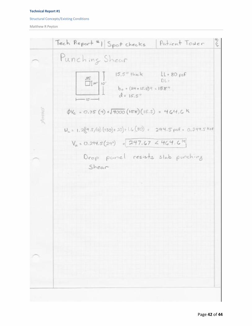
Drop Panels/Punching Shear Spot Check The slab and column connection is accompanied by a 10’ x 10’ x 6” drop panel see in Figure 12. This
panel is used to prevent the columns from punching thought the slab via shear. The shear resisting
capability of the Drop panel is a function of its area and it
depth. The capacity of the drop panels to resist the shear
created by the drop panels greatly exceeds the needed shear
capacity which could be explained by the sizing increments of
panels due to ease of construction. Details of this analysis can
be found in appendix IIII.
Slab Spot Check The slab consists of square bays that are 29’ x 29’ with drop panels and no connecting beams. An
interior bay was chosen to analyze for this spot check (Figure 13), using the ACI direct design method of
analysis of a two way slab. During this analysis a slab thickness of 9.5” was used to check the structural
engineer’s design for the slab of the tower. The results of the analysis did not correspond to the slab
sizing of the tower because the design moments were greater than those of the slabs capacity. Detailed
calculations are provided in appendix IIII.
Figure 11: Spot Check Column G4
Figure 12: Spot Check Drop Panel

Technical Report #1
Structural Concepts/Existing Conditions
Matthew R Peyton
Page 13 of 44
Conclusion Technical Report #1 is an investigation and analysis of the structure for the Patient Tower in an attempt
to better understand the design of the building. This report includes detailed descriptions and
calculations of the different aspects of the structural system including the floor system the lateral
supporting system and the gravity resisting system.
Calculations were run on individual members to verify the structural engineer’s calculations. Most of the
spot checks that were calculated verified that the structure of the tower was oversized accept for the
design of the floor slab. This floor slab will need to be reevaluated in the next report to make sure that
it is adequate.
Figure 13: Spot Check Slab

Technical Report #1
Structural Concepts/Existing Conditions
Matthew R Peyton
Page 14 of 44
Appendix I This section of Technical Report #1 is where the supplementary information for the layout and design
for the Hospital Patient Tower can be found.

Technical Report #1
Structural Concepts/Existing Conditions
Matthew R Peyton
Page 15 of 44
North Ground Floor Plan
South Ground Floor Plan

Technical Report #1
Structural Concepts/Existing Conditions
Matthew R Peyton
Page 16 of 44
Ground Floor Plan
North 1st Floor Plan
South 1st Floor Plan

Technical Report #1
Structural Concepts/Existing Conditions
Matthew R Peyton
Page 17 of 44
South Typical Floor Plan
North Typical Floor Plan

Technical Report #1
Structural Concepts/Existing Conditions
Matthew R Peyton
Page 18 of 44
Two-way flat slab column strip rebar
Two-way flat slab notation

Technical Report #1
Structural Concepts/Existing Conditions
Matthew R Peyton
Page 19 of 44
Appendix II This section of Technical Report #1 is where the supplementary information for the Wind load analysis
for the Hospital Patient Tower can be found.

Technical Report #1
Structural Concepts/Existing Conditions
Matthew R Peyton
Page 20 of 44
Wind Load Parameters
Wind directionality factor (kd) 0.85
Exposure Category B
Topographic Factor (Kzt) 1.0
Gust Effect Factor (G) 0.85
Enclosure classification Enclosed
Internal pressure coefficient (GCpi) ± 0.18
North - South Direction
Height Kz qz Wind Pressures
Wind N-S Lee N-S Total N-S
146 1.102 34.53 29.69 -20.89 50.58
140 1.09 34.15 29.44 -20.89 50.32
120 1.04 32.58 28.37 -20.89 49.26
100 0.99 31.02 27.31 -20.89 48.19
90 0.96 30.08 26.67 -20.89 47.55
80 0.93 29.14 26.03 -20.89 46.92
70 0.89 27.88 25.18 -20.89 46.06
60 0.85 26.63 24.32 -20.89 45.21
50 0.81 25.38 23.47 -20.89 44.36
40 0.76 23.81 22.41 -20.89 43.29
30 0.7 21.93 21.13 -20.89 42.02
25 0.66 20.68 20.28 -20.89 41.16
20 0.62 19.42 19.42 -20.89 40.31
0-15 0.57 17.86 18.36 -20.89 39.25
Building Information
Number of Stories 12
Building Height (feet) 146
N-S Building Length (feet) 191
E-W Building Length (feet) 90
L/B in N-S Direction 2.12
L/B in E-W Direction 0.47

Technical Report #1
Structural Concepts/Existing Conditions
Matthew R Peyton
Page 21 of 44
East - West Direction
Height Kz qz Wind Pressures
Wind E-W Lee E-W Total E-W
146 1.102 34.53 29.69 -13.98 43.67
140 1.09 34.15 29.44 -13.98 43.42
120 1.04 32.58 28.37 -13.98 42.35
100 0.99 31.02 27.31 -13.98 41.29
90 0.96 30.08 26.67 -13.98 40.65
80 0.93 29.14 26.03 -13.98 40.01
70 0.89 27.88 25.18 -13.98 39.16
60 0.85 26.63 24.32 -13.98 38.31
50 0.81 25.38 23.47 -13.98 37.45
40 0.76 23.81 22.41 -13.98 36.39
30 0.7 21.93 21.13 -13.98 35.11
25 0.66 20.68 20.28 -13.98 34.26
20 0.62 19.42 19.42 -13.98 33.41
0-15 0.57 17.86 18.36 -13.98 32.34
North - South Direction
Floor Height (ft.)
Story Height
(ft.)
Wind Pressures (psf) Story Force (Kips)
Story Shear (Kips)
Overturning moment (kips - Ft)
Wind N-S Lee N-S Total N-S
Roof 146 15 29.69 -20.89 50.58 68.28 0.00 0.00
11 131 11.5 29.44 -20.89 50.33 52.09 68.28 9969.32
10 119.5 11.5 28.37 -20.89 49.26 50.98 120.37 6823.99
9 108 11.5 29.3 -20.89 50.19 51.95 171.36 6092.60
8 96.5 11.5 28.3 -20.89 49.19 50.91 223.31 5610.24
7 85 11.5 27.5 -20.89 48.39 50.08 274.22 4912.97
6 73.5 11.5 25.36 -20.89 46.25 47.87 324.30 4257.11
5 59.5 14 27.3 -20.89 48.19 60.72 372.17 3518.35
4 48 11.5 24.2 -20.89 45.09 46.67 432.89 3612.80
3 36.5 11.5 22.84 -20.89 43.73 45.26 479.56 2240.07
2 25 11.5 19.8 -20.89 40.69 42.11 524.82 1652.01
1 13.5 13.5 18.36 -20.89 39.25 47.69 566.93 1052.85
Ground 0 0 0 0 0 0.00 614.62 643.80
Sum 50386.12

Technical Report #1
Structural Concepts/Existing Conditions
Matthew R Peyton
Page 22 of 44
East - West Direction
Floor Height (ft.)
Story Height
(ft.)
Wind Pressures (psf) Story Force (Kips)
Story Shear (Kips)
Overturning moment (kips - Ft)
Wind E-W Lee E-W Total E-W
Roof 146 15 29.69 -13.98 43.67 125.11 0.00 0.00
11 131 11.5 29.44 -13.98 43.42 95.37 125.11 18266.72
10 119.5 11.5 28.37 -13.98 42.35 93.02 220.49 12493.74
9 108 11.5 29.3 -13.98 43.28 95.06 313.51 11116.10
8 96.5 11.5 28.3 -13.98 42.28 92.87 408.57 10266.97
7 85 11.5 27.5 -13.98 41.48 91.11 501.44 8961.76
6 73.5 11.5 25.36 -13.98 39.34 86.41 592.55 7744.42
5 59.5 14 27.3 -13.98 41.28 110.38 678.96 6351.16
4 48 11.5 24.2 -13.98 38.18 83.86 789.34 6567.77
3 36.5 11.5 22.84 -13.98 36.82 80.88 873.21 4025.39
2 25 11.5 19.8 -13.98 33.78 74.20 954.08 2951.94
1 13.5 13.5 18.36 -13.98 32.34 83.39 1028.28 1854.94
Ground 0 0 0 0 0 0.00 1111.67 1125.75
Sum 91726.67

Technical Report #1
Structural Concepts/Existing Conditions
Matthew R Peyton
Page 23 of 44

Technical Report #1
Structural Concepts/Existing Conditions
Matthew R Peyton
Page 24 of 44

Technical Report #1
Structural Concepts/Existing Conditions
Matthew R Peyton
Page 25 of 44

Technical Report #1
Structural Concepts/Existing Conditions
Matthew R Peyton
Page 26 of 44

Technical Report #1
Structural Concepts/Existing Conditions
Matthew R Peyton
Page 27 of 44

Technical Report #1
Structural Concepts/Existing Conditions
Matthew R Peyton
Page 28 of 44

Technical Report #1
Structural Concepts/Existing Conditions
Matthew R Peyton
Page 29 of 44

Technical Report #1
Structural Concepts/Existing Conditions
Matthew R Peyton
Page 30 of 44

Technical Report #1
Structural Concepts/Existing Conditions
Matthew R Peyton
Page 31 of 44
Appendix III This section of Technical Report #1 is where the supplementary information for the seismic analysis for
the Hospital Patient Tower can be found.

Technical Report #1
Structural Concepts/Existing Conditions
Matthew R Peyton
Page 32 of 44
General Seismic Information
Occupancy III
Site Class D
Seismic Design Category B
Short Period Spectral Response
Ss 13.5 % g
Spectral Response (1 Sec.) S1 5.5% g
Maximum Short Period Spectral Response
SMS 0.216
Maximum Spectral Response (1 Sec.)
SM1 0.132
Design Short Spectral Response
SDS 0.144
Design Spectral Response (1 Sec.)
SD1 0.088
Response Modification Coefficient
R 6
Seismic Response Coefficient
CS 0.0218
Effective Period T 0.84
Base Shear (k) 958.76
Overturning Moment (k-ft.) 94671.14

Technical Report #1
Structural Concepts/Existing Conditions
Matthew R Peyton
Page 33 of 44
Slab Weights
Floor Floor (sq. ft.)
Concrete slab (cubic ft.)
Weight (lbs.)
Roof 17026 13478.92 2021837.5
11 17026 13478.92 2021837.5
10 17026 13478.92 2021837.5
9 17026 13478.92 2021837.5
8 17026 13478.92 2021837.5
7 17026 13478.92 2021837.5
6 17026 13478.92 2021837.5
5 17026 14897.75 2234662.5
4 17026 13478.92 2021837.5
3 17026 13478.92 2021837.5
2 25889 20495.46 3074318.75
1 25889 20495.46 3074318.75
Ground 25889
Sum 222038 177198.9167 26579837.5
Column and Misalanius Weights
Column Size Area (sq. ft.)
Number Total Sq. ft.
Cubic ft. Weight (lbs.)
24" x 24" 4 110 440 5280 792000
12" x 18" 1.5 97 145.5 1746 261900
12" x 24" 2 3 6 72 10800
18" x 18" 2.25 3 6.75 81 12150
26" x 26" 4.69 2 9.38 112.56 16884
28" x 28" 5.44 4 21.76 261.12 39168
Sum 219 7552.68 1132902
Shear walls 148 21608 3241200
Drop Panels 20 219 4380 24090 3613500
Curtain walls 82052 1641040
Superimposed 3330570
MEP 4440760

Technical Report #1
Structural Concepts/Existing Conditions
Matthew R Peyton
Page 34 of 44
Floor Height hx (ft.)
Story Height
(ft.)
Story Weight wx
(lbs.)
hxk wx*hx
k Cvx Lateral Force Fx (Kips)
Shear Force Vx
(Kips)
Moment Mx (Kips - ft.)
Roof 146 15 2022 340.64 688769.63 0.10 99.40 0.00 0.00
11 131 11.5 3472 300.06 1041806.67 0.16 150.35 99.40 14512.25
10 119.5 11.5 3472 269.48 935621.44 0.14 135.02 249.75 19695.47
9 108 11.5 3472 239.39 831161.68 0.13 119.95 384.77 16135.26
8 96.5 11.5 3472 209.84 728579.04 0.11 105.14 504.72 12954.40
7 85 11.5 3472 180.89 628058.16 0.09 90.64 609.86 10146.40
6 73.5 11.5 3472 152.60 529829.22 0.08 76.46 700.50 7704.18
5 59.5 14 3472 119.17 413775.30 0.06 59.71 776.96 5619.93
4 48 11.5 3472 92.69 321834.03 0.05 46.45 836.67 3552.95
3 36.5 11.5 3472 67.28 233594.37 0.04 33.71 883.12 2229.36
2 25 11.5 4524 43.21 195484.54 0.03 28.21 916.83 1230.45
1 13.5 13.5 4524 21.01 95063.35 0.01 13.72 945.04 705.28
Ground 0 0 1450 0 0.00 0.00 0.00 958.76 185.21
∑(wxhxk) = 6643577.42 ∑Fx = Base Shear = 958.76 Kips Overturning Moment = 94671.14 Kips - Ft

Technical Report #1
Structural Concepts/Existing Conditions
Matthew R Peyton
Page 35 of 44

Technical Report #1
Structural Concepts/Existing Conditions
Matthew R Peyton
Page 36 of 44

Technical Report #1
Structural Concepts/Existing Conditions
Matthew R Peyton
Page 37 of 44

Technical Report #1
Structural Concepts/Existing Conditions
Matthew R Peyton
Page 38 of 44
Appendix IIII This section of Technical Report #1 is where the supplementary information for the spot check analysis
for the Hospital Patient Tower can be found.

Technical Report #1
Structural Concepts/Existing Conditions
Matthew R Peyton
Page 39 of 44

Technical Report #1
Structural Concepts/Existing Conditions
Matthew R Peyton
Page 40 of 44

Technical Report #1
Structural Concepts/Existing Conditions
Matthew R Peyton
Page 41 of 44
Technical Report #1
Structural Concepts/Existing Conditions
Matthew R Peyton
Page 42 of 44

Technical Report #1
Structural Concepts/Existing Conditions
Matthew R Peyton
Page 43 of 44

Technical Report #1
Structural Concepts/Existing Conditions
Matthew R Peyton
Page 44 of 44