Embed Size (px)
Citation preview
1
BENDING AND PUNCHING SHEAR STRENGTH OF FIBER-REINFORCED GLASS CONCRETE SLABS
By Bin MU♣ and Christian Meyer♦
November 2002
♣ Post-doctoral research fellow, Center for Advanced Cement-Based Materials, Northwestern University. He received his MS and BS in solid mechanics from PRC, and his PhD from the Hong Kong University of Science and Technology. His research interests include fracture mechanics of concrete and fiber-reinforced concrete, durability of high performance concrete, extrusion technology and finite element method. ♦ Professor of Civil Engineering and Engineering Mechanics, Columbia University. He received his PhD from the University of California at Berkeley. He is a member of ACI Committee 446, Fracture Mechanics; ACI Committee 544 Fiber-Reinforced Concrete; and 447, Finite Element Analysis of Reinforced Concrete Structures. His research interests include concrete structures and materials, structural analysis and design. The corresponding author, Tel.: 212-854-3428; Fax: 212-854-6267; Email: [email protected]
2
Bending and Punching Shear Resistance of Fiber-Reinforced Glass Concrete Slabs By Bin MU and Christian Meyer
An experimental study was carried out on fiber-reinforced glass aggregate concrete slabs
under a central patch load. The slab specimens were reinforced either with randomly
distributed short fibers or with continuous fiber mesh with equal fiber volume ratios. The
influences of fiber type, form and volume ratio on the two-way bending behavior and
punching shear capacity of the glass concrete slab were investigated.
Test results revealed that fiber mesh is decidedly more effective in bending than
randomly distributed fibers, however randomly distributed fibers are somewhat more
effective in punching shear. The shape and location of the critical punching shear
perimeter is independent of fiber type, form and volume ratio. But crushed glass
aggregate has some influence on both strength and failure mode of the slabs.
Keywords: concrete slabs; glass concrete; punching shear; two-way bending; fabric mesh; fiber-reinforced
concrete.
3
INTRODUCTION
Thin-sheet concrete products have attracted considerable attention in recent
years1,2. There are numerous potential applications, which previously were difficult or
impossible to realize with conventional concrete materials. The introduction of non-
ferrous reinforcement, either in the form of randomly distributed short fibers or
continuous fiber mesh greatly reduces the cover requirements, thereby facilitating
significant reductions of minimum thicknesses for such thin sheets. Their mechanical
behavior differs considerably from that of conventional reinforced concrete panels, and
so do the manufacturing processes. Thin-sheet products are often manufactured using
extrusion and pultrusion processes.
If thin-sheet concrete panels are subjected to loads, conventional structural theory
needs to be applied to assure that such loads can safely be resisted. Given their small
thicknesses, punching shear performance may become important, especially if the
reinforcement is dimensioned for flexural strength and the panels are subjected to large
concentrated forces either by design or by accident.
Specific architectural surface treatments can open up an entire new category of
applications such as claddings, veneers and face panels, which previously were mostly
the domain of natural stone. Also the use of crushed glass particles as aggregate lends
itself to a multitude of architectural treatments, including polished surfaces or exposed
aggregate finishes3,4. The problem of alkali-silica reaction (ASR) needs to be considered,
but technology exists to control the potentially damaging effects5,6.
4
It was the objective of the study presented here to evaluate the bending and
punching shear strength of fiber-reinforced concrete slabs with glass aggregate. The
reinforcement consisted of either randomly distributed short fibers or continuous woven
fiber mesh. Whereas short fibers have the advantage of simplicity and economy of
production, performance specifications of thin-sheet products are more readily satisfied
with continuous fiber mesh, especially if large fiber volume ratios are called for7,8,9.
A considerable body of literature exists on the punching shear behavior of
reinforced concrete slabs. When modeling such behavior for small-scale laboratory
experiments it is important to accurately reproduce the boundary conditions that exist in
real structures. Slabs are typically supported continuously along their edges and
restrained by adjacent panels to various degrees. Such restraints typically affect the in-
plane deformations of a representative slab panel subjected to a concentrated transverse
load by forcing membrane or arch action. This can alter completely the load-carrying
characteristics and failure mode10-12, by greatly enhancing the punching shear capacity of
such restrained slab panels.
The one-way bending behavior of fiber-reinforced concrete members with glass
aggregate has been reported earlier13. This previous study showed that fiber mesh is
clearly more effective than randomly distributed short fibers as reinforcement. However,
the proper design of concrete slabs, whether used for thin-sheet products or more
conventional structural slabs, depends on a thorough understanding of the two-way
bending and punching shear behavior.
This paper reports on the experimental study of slab elements reinforced either with
randomly distributed short fibers or continuous fiber mesh. The effect of the glass
5
aggregate is assessed by also testing samples produced with regular river sand as
aggregate. Three types of materials were studied for reinforcement: alkali-resistant glass
(AR-glass), PVA, and polypropylene. In the punching shear test, only AR-glass fibers
were studied.
RESEARCH SIGNIFICANCE
Fiber mesh reinforced thin-sheet concrete products with crushed glass aggregate
lend themselves to numerous novel applications. If used for relatively large panels, their
two-way bending and punching shear behavior needs to be known. A characterization of
such behavior will facilitate the use of such panels for applications that until now was
primarily the domain of natural stone. The research reported herein provides needed
insights for their safe use.
MATERIALS AND TEST PROGRAM
Materials
A single concrete mix design was used throughout the test program. The
water/binder ratio was 0.35. Crushed post-consumer glass was used as the aggregate,
with maximum particle size #16. Strictly speaking, the material should therefore be
referred to as mortar instead of concrete. The cement/aggregate ratio was 1:2. 15% of the
Type III cement was replaced by metakaolin to suppress the potentially harmful effects of
alkali-silica reaction5. Suitable admixtures were used to obtain the desired workability.
The compressive strength of the mix, tested on 2-inch cubes after 28 days was 97.7 MPa.

6
Two-way bending test
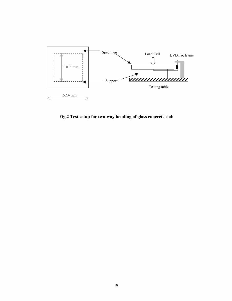
The test specimens were square plates of 152.4 mm length and 19 mm thickness,
loaded at their center with a round steel pressure head of 12.7 mm diameter to simulate a
concentrated load. The clear test span was 101.6 mm (Fig. 2). The load was applied by a
50 kN Instron test machine under displacement control at a rate of 1.0 mm/min. A LVDT
was mounted to measure indirectly the center deflections such that extraneous influences
from the supports and loading fixtures were eliminated (Fig. 2). Three data channels,
representing applied load, displacement of load cell and center displacement of specimen,
were connected to a PC and recorded by Labview software.
Two sets of specimens were prepared, one reinforced with short random fibers,
distributed over half of the slab on the tension side, and one with fiber mesh. Three types
of fibers were studied: AR-glass fibers with 12.7 mm long and tensile strength of 1800
MPa, PVA fibers with 6 mm long and tensile strength of 1400 MPa, and polypropylene
fibers with 12.7 mm long and tensile strength of 620 MPa. Two fiber volumes were
considered for each fiber type, designated as Vf and 2Vf, corresponding to one and two
layers of the fabric meshes. For polypropylene fibers, Vf = 0.67%, while for glass fibers,
Vf = 0.25% and for PVA fibers, Vf = 0.44%. The mesh-reinforced specimens contained
one or two layers of mesh, positioned on the tension side of the beam with 2mm concrete
cover. Both the AR-glass and the PVA mesh had a 5 x 5mm grid, while the grid of the
polypropylene mesh was 4.5 x 4.5mm. The former two were woven and the third one
knitted (Fig. 1). All specimens were demolded one day after casting and placed in a
moisture room for two months before being tested. Each batch consisted of three
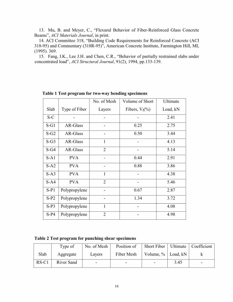
samples. Table 1 contains an overview of the test program.

7
Punching shear test
To eliminate warping of the slabs, circular specimens with a diameter of 127 mm
and thickness of 19 mm were cast. The specimens were supported on a simple ring with a
diameter of 101.6mm. The test setup, testing machine, and loading rate were similar as in
the two-way bending tests and as shown in Fig. 2.
The specimens were reinforced with either short random AR-glass fibers distributed
throughout the slabs or AR-glass fiber mesh. The mesh-reinforced specimens contained
one or two layers of mesh (Vf = 0.25% or 2Vf = 0.50%), positioned either on the slab’s
tension side, compression side, or both, with 2mm concrete cover in each case. All
specimens were demolded one day after casting and placed in a moisture room for seven
days before being tested. Two control batches were cast, one with plain glass concrete
and the other with plain normal concrete, using river sand as aggregate. To achieve the
arch action, a plastic tube with a diameter of 127mm and thickness of 6.35mm was used
to confine the specimens. The test program is summarized in Table 2.
TWO-WAY BENDING TEST RESULTS
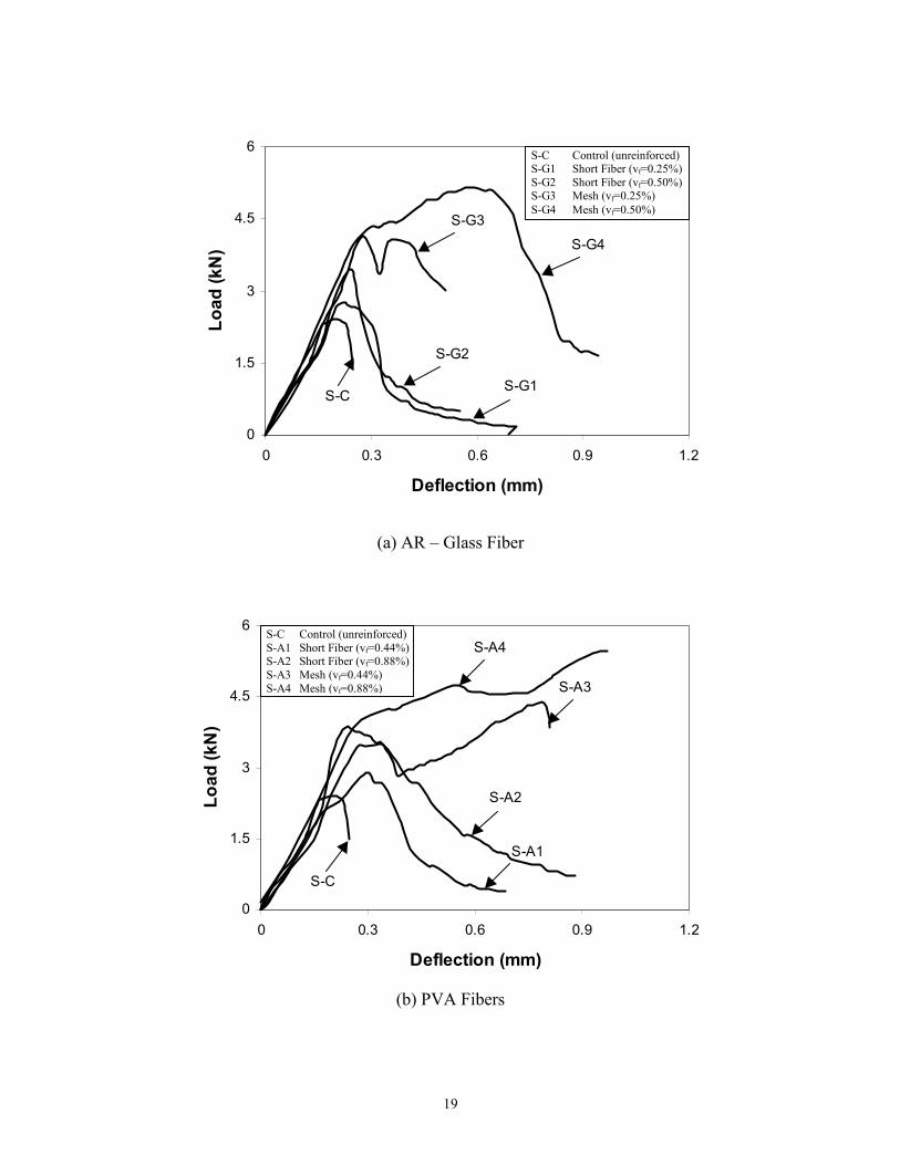
The load-deflection curves for all 13 test specimens are shown in Fig. 3. Each of the
three plots contains five curves: one for the control specimen without fiber (S-C), two for
the specimens reinforced with randomly distributed short fibers (Vf and 2Vf), and two for
the specimens reinforced with one or two layers of fiber mesh (Vf and 2Vf). Figs. 3a,b,c
show the responses of specimens reinforced with AR-glass, PVA, and polypropylene
fibers, respectively. The ultimate strengths are summarized in Table 1.
8
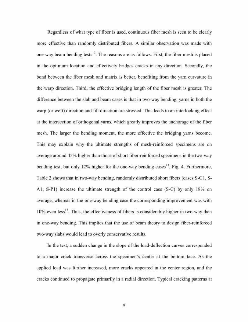
Regardless of what type of fiber is used, continuous fiber mesh is seen to be clearly
more effective than randomly distributed fibers. A similar observation was made with
one-way beam bending tests13. The reasons are as follows. First, the fiber mesh is placed
in the optimum location and effectively bridges cracks in any direction. Secondly, the
bond between the fiber mesh and matrix is better, benefiting from the yarn curvature in
the warp direction. Third, the effective bridging length of the fiber mesh is greater. The
difference between the slab and beam cases is that in two-way bending, yarns in both the
warp (or weft) direction and fill direction are stressed. This leads to an interlocking effect
at the intersection of orthogonal yarns, which greatly improves the anchorage of the fiber
mesh. The larger the bending moment, the more effective the bridging yarns become.
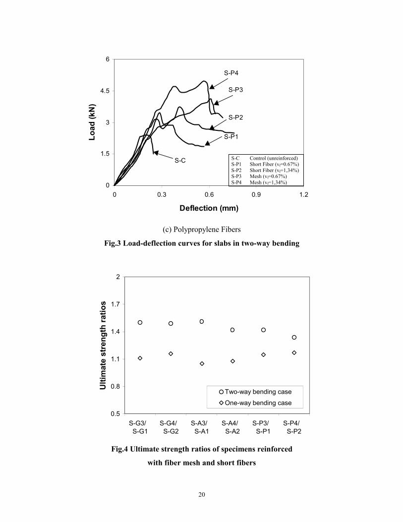
This may explain why the ultimate strengths of mesh-reinforced specimens are on
average around 45% higher than those of short fiber-reinforced specimens in the two-way
bending test, but only 12% higher for the one-way bending cases13, Fig. 4. Furthermore,
Table 2 shows that in two-way bending, randomly distributed short fibers (cases S-G1, S-
A1, S-P1) increase the ultimate strength of the control case (S-C) by only 18% on
average, whereas in the one-way bending case the corresponding improvement was with
10% even less13. Thus, the effectiveness of fibers is considerably higher in two-way than
in one-way bending. This implies that the use of beam theory to design fiber-reinforced
two-way slabs would lead to overly conservative results.
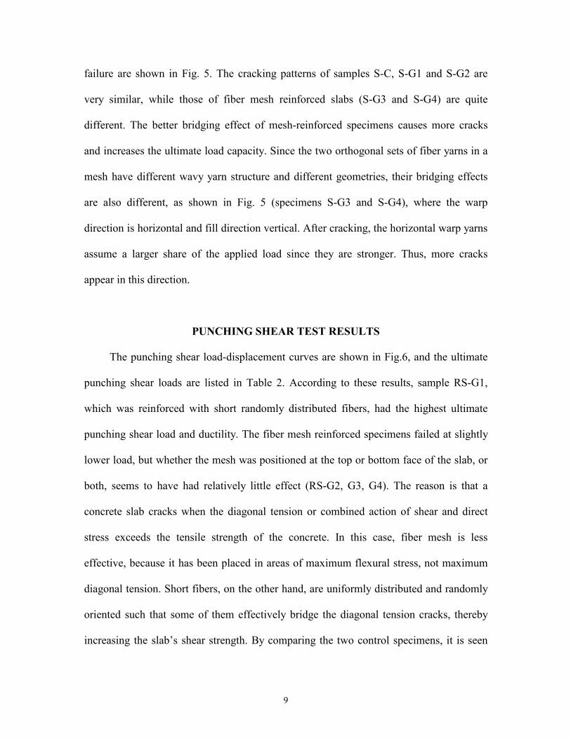
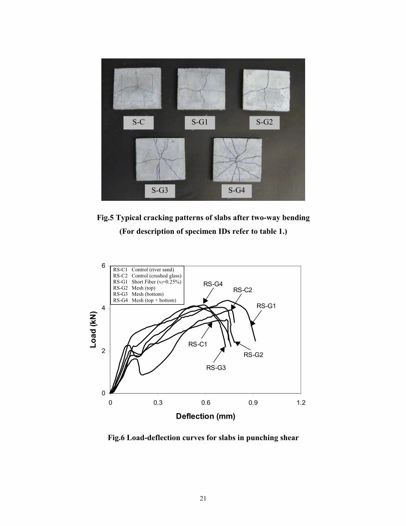
In the test, a sudden change in the slope of the load-deflection curves corresponded
to a major crack transverse across the specimen’s center at the bottom face. As the
applied load was further increased, more cracks appeared in the center region, and the
cracks continued to propagate primarily in a radial direction. Typical cracking patterns at
9
failure are shown in Fig. 5. The cracking patterns of samples S-C, S-G1 and S-G2 are
very similar, while those of fiber mesh reinforced slabs (S-G3 and S-G4) are quite
different. The better bridging effect of mesh-reinforced specimens causes more cracks
and increases the ultimate load capacity. Since the two orthogonal sets of fiber yarns in a
mesh have different wavy yarn structure and different geometries, their bridging effects
are also different, as shown in Fig. 5 (specimens S-G3 and S-G4), where the warp
direction is horizontal and fill direction vertical. After cracking, the horizontal warp yarns
assume a larger share of the applied load since they are stronger. Thus, more cracks
appear in this direction.
PUNCHING SHEAR TEST RESULTS
The punching shear load-displacement curves are shown in Fig.6, and the ultimate
punching shear loads are listed in Table 2. According to these results, sample RS-G1,
which was reinforced with short randomly distributed fibers, had the highest ultimate
punching shear load and ductility. The fiber mesh reinforced specimens failed at slightly
lower load, but whether the mesh was positioned at the top or bottom face of the slab, or
both, seems to have had relatively little effect (RS-G2, G3, G4). The reason is that a
concrete slab cracks when the diagonal tension or combined action of shear and direct
stress exceeds the tensile strength of the concrete. In this case, fiber mesh is less
effective, because it has been placed in areas of maximum flexural stress, not maximum
diagonal tension. Short fibers, on the other hand, are uniformly distributed and randomly
oriented such that some of them effectively bridge the diagonal tension cracks, thereby
increasing the slab’s shear strength. By comparing the two control specimens, it is seen
10
that sample RS-C2 with crushed glass as aggregate has a higher punching shear strength
than the sample RS-C1 with river sand as aggregate. This may be due to the glass
aggregates’ irregular shapes and sharp angles, which can increase shear transfer across
cracks.
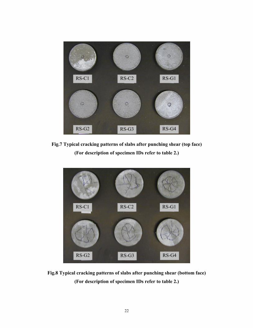
Figures 7 and 8 present the crack patterns of confined specimens after punching
shear failure. The crack patterns at the top face were all nearly identical, with a small
circle of a diameter, which is almost the same as that of the loading plate. On the bottom
face, the crack patterns of the last five specimens are very similar, Fig. 8. Flexure cracks
do not appear to be extensive. Maximum principal tension occurs near the mid-plane,
initiating web-shear cracks that propagate toward the top and bottom faces of the slab and
creating the typical conical failure surface.
When comparing the bottom face cracks of sample RS-C1 with that of RS-C2, Fig.
8, a marked difference is noted. In RS-C1, near-vertical flexural cracks formed at the
bottom face when the applied moment exceeded the cracking moment. With increasing
load, these cracks propagated toward the middle surface of the slab to form flexure-shear
cracks, followed by the appearance of a transverse cracks that then led to punching shear
failure. This observation implies that glass aggregate gives a higher flexural strength than
ordinary river sand, possibly because the irregular shapes and sharp angle increase the
bond between aggregate and matrix. Also the punching shear strength of the glass
aggregate concrete slab is higher. According to the load-deflection curves of Fig.5,
specimens made with glass aggregate are not more brittle than those made with river
sand.
11
To further investigate the relationship between flexural and punching shear
strengths of slabs and the effect of confinement, two additional control specimens were
prepared and tested, A-C1 with river sand and A-C2 with glass aggregate. The mix
proportions were identical to those of specimens RS-C1 and RS-C2, but the boundary
was left unconfined. Both specimens failed in typical flexure. The flexural cracks
initiated at the center of the bottom face and propagated towards the circular edge. The
ultimate strengths are given in Table 2 and found to be lower than those of the specimens
with constrained edges. As is known, the edge confinement facilitates compressive
membrane action, which increases the shear friction across cracks and therefore the
punching shear strength. In fact, this boundary restraint also increases the flexural
strength, and this increase is proportional to the slab thickness.
Whether the edge is constrained or not, specimens with glass aggregate have higher
punching shear capacity than those with river sand, Table 2. By comparing the strength of
specimen RS-C1 with that of RS-C2 and A-C1 with A-C2, it is seen that the strength
difference is larger for the unconfined case (18%) than the one with confinement (12%).
Similarly, the confinement increases the sample with sand by 21% and that with glass by
16%. This implies that the specimen with river sand tends to expand in the radial
direction more than that with glass aggregate or the flexural cracks of the specimen with
river sand are wider than that of the specimen with glass aggregate. This means that glass
aggregate provided a better bridging effect in the specimen than the normal river sand
due to its irregular and sharp shapes. So, the specimen with river sand is more likely to be
influenced by the boundary restraint. Whereas the confinement changed the failure mode
of the glass concrete slab from a flexural to a punching shear failure, in the case of the
12
specimen with river sand, the two failure modes were coupled. This implies that the
flexural resistance of the glass concrete slab is more easily improved by the arch action
than the ordinary concrete slab. From a design point of view, this result suggests that the
restrained glass concrete slab is more likely to fail in punching shear. In either case,
proper reinforcement has to be provided.
To calculate the shear stress associated with punching shear failure, the failure load
is usually divided by the slab depth, h, and the average circumference of the failure
surface, l. l is determined on the assumption that the effective section is located a distance
kh from the face of the loaded area and has a geometrically similar shape. For a round
patch load with diameter d, the effective length, l, can be expressed as14:
)( khdl += π (1)
The failure surface is typically assumed to have a 45o slope, for which k=1. The
value of k can be determined by measuring the top and bottom diameters of the failure
surface. Using the average of six measurements, the value of k was estimated for each
slab using the following expression:
h
dDk2−= (2)
where D is the average diameter of the bottom face of the failure cone. The values thus
obtained are listed in Table 2. They vary from 1.62 to 1.73, with a mean value of 1.68,
which corresponds to a failure surface inclination angle of about 30o. There are no
significant differences between the plain, short fiber-reinforced and fiber mesh-reinforced
glass concrete specimens. This k-value agrees with others reported in the literature12,15,
where values of about 1.5 were given for steel fiber-reinforced concrete slabs with either
confined or free boundary.
13
CONCLUSIONS
The use of crushed waste glass as aggregate for concrete is a relatively novel
concept. The reservations against such use out of concern about long-term alkali-silica
reaction problems have been addressed by extensive research efforts reported elsewhere.
Solutions to overcome ASR-related problems are available, therefore it is now possible to
address other issues related to glass concrete products. The question of flexural and
punching shear of fiber-reinforced glass concrete slabs has been the topic of this paper.
Two-way bending and punching shear behavior of slabs with and without restraints
are two different phenomena. The introduction of fiber reinforcement, either short and
randomly distributed or fiber mesh, makes them more difficult to analyze. Both types of
reinforcement are gaining acceptance in practice. The attractiveness of short fibers is due
to their simplicity and economy of concrete production, especially for lower fiber volume
ratios. The use of high-performance polymeric fiber mesh has gained increased attention
in structural engineering applications since the mid-1980’s. Advantages of such fabric
reinforcements include high strength, low unit weight and ease of coiling and handling.
The fabric meshes are especially suitable for automated fabrication processes for thin
sheet products (such as pultrusion or extrusion), as well as for repair and strengthening of
existing structures. Such thin sheet reinforcements can provide a complete integrated
armature system to enhance the bending and shear resistance of beams and slabs.
The study reported herein systematically compared the reinforcing effects of short
randomly distributed fibers and fiber meshes on both the two-way bending and punching
shear behavior of glass concrete slabs. It permits to draw the following conclusions:
14
1. For two-way bending, fiber mesh is very efficient as reinforcement. Even at the
very low fiber volume ratio of 0.25%, strain-hardening response can be achieved.
For the same fiber volume ratio, the fiber mesh is clearly superior over randomly
distributed short fibers, because of better interfacial bond between the matrix and
the yarns and the locking phenomenon at the yarn intersections. This superior
reinforcing effect is even more pronounced in two-way bending than was
observed in one-way bending.
2. Short randomly distributed fibers improve the flexural strength and ductility of
glass concrete slabs, but do not change their failure modes. The yield lines are
very similar to those of unreinforced glass concrete slabs. For the same fiber
volume ratio, fiber mesh not only greatly increases the strength and ductility of
glass concrete slabs but also forces multiple cracking and consequently strain
hardening.
3. All restrained circular concrete slabs failed in punching shear. Glass concrete
slabs reinforced with short randomly distributed fibers had somewhat higher shear
strengths than those reinforced with fiber mesh, whether this was positioned on
the slab tension side, compression side, or both. In specimens with boundary
restraints, the beneficial effect of arch action on the flexural strength is more
pronounced in the case of glass concrete than with ordinary concrete.
4. Fiber form and volume ratio, fiber mesh position and restrained boundary
condition do not significantly influence the shape of the punching shear failure
cone.
15
ACKNOWLEDGEMENTS
The senior author was supported by Echo Environmental, Inc., New York and Columbia
University. This support is gratefully acknowledged. The authors also thank Kuraray Co.
Ltd., Nippon Electric Glass American, Inc. and Synthetic Industries, Inc. for providing
the PVA, glass and polypropylene fibers and fiber mesh.
REFERENCES
1. “High-Performance Fiber-Reinforced Concrete Thin Sheet Products”, ACI Special Publication SP 190, 2000, American Concrete Institute, Farmington Hills, MI.
2. Daniel, J.I. and S.P. Shah, eds., “Thin-Section Fiber Reinforced Concrete and Ferrocement”, ACI Special Publication SP 124, 1990, American Concrete Institute, Farmington Hills, MI.
3. Jin, W., Meyer, C. and Baxter, S., “Glascrete – Concrete with Glass Aggregate”, ACI Materials Journal, 97, 2000, pp.208-213.
4. Meyer, C., Shimanovich, S. and Vilkner, G., “Precast Concrete Wall Panels with Glass Concrete”, New York State Energy Res. and Develop. Authority, Albany, NY, in print.
5. Jin, W., “Alkali-Silica Reaction in Concrete with Glass Aggregate: A Chemo-Physicomechanical Approach”, Ph.D. Thesis, Columbia University, 1998.
6. Meyer, C. and Baxter, S., “Use of Recycled Glass for Concrete Masonry”, New York State Energy Res. and Develop. Authority, Albany, NY, Report No. 97-15, 1997.
7. Swamy, R.N. and Hussin, M.W., “Woven Polypropylene Fabrics – An Alternative to Asbestos for Thin Sheet Application”, Fiber Reinforced Cement and Concrete, Recent Development, R.N. Swamy and B. Barr, Eds, Elsevier Applied Science, 1989, pp.90-100.
8. Peled, A., Bentur, A. and Yankelevsky, D., “Flexural performance of cementitious composites reinforced with woven fabrics”, Journal of Materials in Civil Engineering, 1999, pp.325-330.
9. Reinhardt, H.W., “Integral Formwork Panels Made of Glass Fiber-reinforced Concrete”, High-Performance Fiber-Reinforced Concrete Thin Sheet Products, A. Peled, S. P. Shah and N. Banthia eds., ACI SP-190, 2000, pp.77-96.
10. Rankin, G.I.B., Niblock, R.A., Skates, A.S., and Long, A.E., “Compressive Membrane Action Strength Enhancement in Uniformly Loaded, Laterally Restrained Slabs”, The Structural Engineering, V.69, No.16, 1999, pp.287-295.
11. Fang, I. K., Lee, J. H. and Chen, C. R., “Behavior of Partially Restrained Slabs under Concentrated Load”, ACI Structural Journal, V.91, No.2, 1994, 133-138.
12. Mansur, M.A., Ahmad, I. and Paramasivam, P., “Punching Shear Behavior of Restrained Ferrocement Slabs”, ACI Structural Journal, V.97, No.5, 2000, 765-773.
16
13. Mu, B. and Meyer, C., “Flexural Behavior of Fiber-Reinforced Glass Concrete Beams”, ACI Materials Journal, in print.
14. ACI Committee 318, “Building Code Requirements for Reinforced Concrete (ACI 318-95) and Commentary (318R-95)”, American Concrete Institute, Farmington Hill, MI, (1995). 369.
15. Fang, I.K., Lee J.H. and Chen, C.R., “Behavior of partially restrained slabs under concentrated load”, ACI Structural Journal, 91(2), 1994, pp.133-139. Table 1 Test program for two-way bending specimens
Slab
Type of Fiber
No. of Mesh
Layers
Volume of Short
Fibers, Vf(%)
Ultimate
Load, kN
S-C - - - 2.41
S-G1 AR-Glass - 0.25 2.75
S-G2 AR-Glass - 0.50 3.44
S-G3 AR-Glass 1 - 4.13
S-G4 AR-Glass 2 - 5.14
S-A1 PVA - 0.44 2.91
S-A2 PVA - 0.88 3.86
S-A3 PVA 1 - 4.38
S-A4 PVA 2 - 5.46
S-P1 Polypropylene - 0.67 2.87
S-P2 Polypropylene - 1.34 3.72
S-P3 Polypropylene 1 - 4.08
S-P4 Polypropylene 2 - 4.98
Table 2 Test program for punching shear specimens
Slab
Type of
Aggregate
No. of Mesh
Layers
Position of
Fiber Mesh
Short Fiber
Volume, %
Ultimate
Load, kN
Coefficient
k
RS-C1 River Sand - - - 3.45 -

17
RS-C2 Crushed Glass - - - 3.88 1.62
RS-G1 Crushed Glass - - 0.25 4.39 1.69
RS-G2 Crushed Glass 1 Top - 4.05 1.70
RS-G3 Crushed Glass 1 Bottom - 4.09 1.67
RS-G4 Crushed Glass 2 Top & Bottom - 4.17 1.73
A-C1 River Sand - - - 2.84 -
A-C2 Crushed Glass - - - 3.35 -
(a) Woven mesh (b) Knitted mesh
Fig.1 Structures of fabric mesh
Warp yarns
Fill yarns Weft yarns
Fill yarns
18
Fig.2 Test setup for two-way bending of glass concrete slab
152.4 mm
101.6 mm
Support
Specimen Load Cell LVDT & frame
Testing table
19
(a) AR – Glass Fiber
(b) PVA Fibers
0
1.5
3
4.5
6
0 0.3 0.6 0.9 1.2
Deflection (mm)
Load
(kN
) S-G4
S-G3
S-G2
S-G1S-C
S-C Control (unreinforced) S-G1 Short Fiber (vf=0.25%) S-G2 Short Fiber (vf=0.50%) S-G3 Mesh (vf=0.25%) S-G4 Mesh (vf=0.50%)
0
1.5
3
4.5
6
0 0.3 0.6 0.9 1.2
Deflection (mm)
Load
(kN
)
S-A4
S-A3
S-A2
S-A1
S-C
S-C Control (unreinforced)S-A1 Short Fiber (vf=0.44%)S-A2 Short Fiber (vf=0.88%)S-A3 Mesh (vf=0.44%) S-A4 Mesh (vf=0.88%)
20
(c) Polypropylene Fibers
Fig.3 Load-deflection curves for slabs in two-way bending
0.5
0.8
1.1
1.4
1.7
2
S-G3/ S-G1
S-G4/ S-G2
S-A3/ S-A1
S-A4/ S-A2
S-P3/ S-P1
S-P4/ S-P2
Ulti
mat
e st
reng
th ra
tios
Two-way bending case
One-way bending case
Fig.4 Ultimate strength ratios of specimens reinforced
with fiber mesh and short fibers
0
1.5
3
4.5
6
0 0.3 0.6 0.9 1.2
Deflection (mm)
Load
(kN
)
S-P4
S-P3
S-P2
S-P1
S-C S-C Control (unreinforced) S-P1 Short Fiber (vf=0.67%) S-P2 Short Fiber (vf=1,34%) S-P3 Mesh (vf=0.67%) S-P4 Mesh (vf=1,34%)
21
Fig.5 Typical cracking patterns of slabs after two-way bending
(For description of specimen IDs refer to table 1.)
Fig.6 Load-deflection curves for slabs in punching shear
0
2
4
6
0 0.3 0.6 0.9 1.2
Deflection (mm)
Load
(kN
)
RS-C1
RS-C2
RS-G1
RS-G2
RS-G3
RS-G4
RS-C1 Control (river sand) RS-C2 Control (crushed glass)RS-G1 Short Fiber (vf=0.25%)RS-G2 Mesh (top) RS-G3 Mesh (bottom) RS-G4 Mesh (top + bottom)
S-C S-G1 S-G2
S-G4 S-G3
22
Fig.7 Typical cracking patterns of slabs after punching shear (top face)
(For description of specimen IDs refer to table 2.)
Fig.8 Typical cracking patterns of slabs after punching shear (bottom face)
(For description of specimen IDs refer to table 2.)
RS-C1 RS-C2 RS-G1
RS-G3 RS-G2 RS-G4
RS-C1 RS-C2 RS-G1
RS-G3 RS-G2 RS-G4