Embed Size (px)
Citation preview

SIRIUSi-XHS®
TECHNICAL REFERENCE MANUALSIRIUSi-XHS® V21-2

SIRIUSi-XHS®TECHNICAL REFERENCE MANUAL
Table of contents
1. About this document 41.1. Legend 41.2. Online versions 5
1.2.1. Online SIRIUSi-XHS® technical reference manual 51.2.2. DewesoftX® User Manual 5
2. Getting started 62.1. Software installation 62.2. Connecting SIRIUSi-XHS® 7
2.2.1. Connection over 3.0. USB 72.2.1.1. Sample rate limitation when connected with USB 7
2.2.2. Connection over EtherNET 72.2.2.1. Sample rate limitation when connected with Ethernet 82.2.2.2. Ethernet configuration on the PC 82.2.2.3. Troubleshooting 9
2.2.3. DewesoftX® settings for SIRIUSi-XHS® 102.2.4. Channel Setup SIRIUSi-XHS® 16
2.3. Simple Measurement 172.3.1. Help - Manual 172.3.2. Analogue channel setup 172.3.3. Sample rate 182.3.4. Measurement Mode 192.3.5. Analyse Mode 19
2.4. Advanced configuration 202.5. Firmware upgrade 212.6. Licensing 222.7. Troubleshooting 23
3. System overview 243.1. Main features 25
3.1.1. Hybrid ADC technology 263.1.2. Perfect synchronization 263.1.3. Open interface protocols 263.1.4. Data Acquisition Software Included for Free 27
3.2. System specifications 273.3. Single slice 283.4. Single slice: Rear side 283.5. Connectors 29
3.5.1. Power in connector 293.5.1.1. Power out connector 29
3.5.2. SYNC connector 303.5.3. CAN 303.5.4. GND connector 31
SIRIUSi-XHS® - V21-22/52

SIRIUSi-XHS®TECHNICAL REFERENCE MANUAL
3.5.5. Ethernet Connector 323.5.6. USB connector 32
4. Module overview 334.1. SIRIUSi-XHS® dimensions 344.2. HV: Specifications 35
4.2.2. HV- Banana Connector 364.2.2. HV: Voltage 36
4.3. LV: Specifications 374.3.1. LV: DSUB connector 38
4.3.1.1. LV: Voltage 384.3.1.2. LV: Current 39
4.3.2. LV: BNC connector 394.4. ACC: Specifications 40
4.4.1. ACC: BNC connector 414.4.1.1. ACC: Voltage, IEPE 41
5. Real-time controller - XCP slave settings 425.1. XCP-Slave module settings 42
5.1.1. XCP output settings ❷ 435.1.2. XCP Event settings ❸ 435.1.3. XCP outputs (channels) ❹ 445.1.4. Generating A2L file ❺ 455.1.5. Download and Upload button ❻ 45
5.2. Start the XCP protocol 45
6. Troubleshooting 466.1. Device not recognized when connected over USB 466.2. Clear static configuration 46
7. Safety instructions 477.1. General Safety Instructions 47
7.1.1. Environmental Considerations 477.1.2. Product End-of-Life Handling 477.1.3. General safety and hazard warnings for all Dewesoft systems 47
8. Notice 508.1. Warranty Information 508.2. Calibration 508.3. Support 508.4. Service/repair 508.5. Restricted Rights 508.6. Printing History 518.7. Copyright 518.8. Trademarks 518.9. Documentation version 52
SIRIUSi-XHS® - V21-23/52

SIRIUSi-XHS®TECHNICAL REFERENCE MANUAL
1. About this document
This is the Technical Reference Manual for SIRIUSi-XHS® device, version V21-2.
SIRIUSi-XHS® is a high performance, high speed line of SIRIUS® real time data acquisition hardwareused for the most demanded power measurements, specially designed for E-mobility applications. Eachsystem also includes a professional license for our award-winning DewesoftX® data acquisition software.
The manual is divided into several chapters. You will find:● A detailed description of the SIRIUSi-XHS® hardware● A description of the connection variants and the pin assignments on the inputs and outputs● A comprehensive introduction to the configuration of the modules using DewesoftX®● Detailed technical data: Specifications, etc.
1.1. Legend
The following symbols and formats will be used throughout the document.
ImportantGives you important information about a subject.Please read carefully!
HintGives you a hint or provides additional information about a subject.
ExampleGives you an example to a specific subject.
Safety symbols in the manual:
WarningCalls attention to a procedure, practice, or condition that could cause the body injury or death
CautionCalls attention to a procedure, practice, or condition that could possibly cause damage toequipment or permanent loss of data.
SIRIUSi-XHS® - V21-24/52

SIRIUSi-XHS®TECHNICAL REFERENCE MANUAL
1.2. Online versions
1.2.1. Online SIRIUSi-XHS® technical reference manualThe most recent version of this manual can be downloaded from our homepage:https://download.dewesoft.com/list/manuals-brochures/hardware-manualsIn the Hardware Manuals section click the download link for the SIRIUSi-XHS® technical referencemanual.
1.2.2. DewesoftX® User ManualThe DewesoftX® tutorials document, provides basics and additional information and examples forworking with DewesoftX® and certain parts of the program.The latest version of the DewesoftX® tutorials can be found here:https://download.dewesoft.com/list/manuals-brochures/software-manualsIn the Software Manuals section click the download link of the DewesoftX® tutorials entry.
ImportantRead safety instructions first in chapter Safety instructions.
SIRIUSi-XHS® - V21-25/52

SIRIUSi-XHS®TECHNICAL REFERENCE MANUAL
2. Getting started
This chapter will help you to install the software, connect your SIRIUSi-XHS® device to the PC viaEthernet or via USB, and will show you how to configure DewesoftX® software.
To follow these steps, you need the following items:● your brand new SIRIUSi-XHS® system (included in the shipment)● your network cable (included in the shipment)● Your USB cable (included in the shipment)● Your PC with Windows 10 and the Dewesoft® software● Note: older versions like Windows® 7 may also work
Hint:As Siriusi-XHS® is a new device and its software functionality is still in the development phase, werecommend using the latest Development or Release Candidate versions. As the FW of the deviceis improving, the newer FW updates are always compatible with latest Development versions. Formore information please contact the support team.
2.1. Software installationFor optimal working, we recommend that you install the latest version of DewesoftX®. If you alreadyhave installed the older version Dewesofti is recommended that you find the newest version on thewebsite under Support/Downloads/DewesoftX section. You can also check if a newer version is availablein software.
Image 1: Check for update
SIRIUSi-XHS® - V21-26/52

SIRIUSi-XHS®TECHNICAL REFERENCE MANUAL
2.2. Connecting SIRIUSi-XHS®In this chapter, you can see the basic instructions for connecting SIRIUSi-XHS® devices over 3.0 USB andRJ-45 ethernet connection. Advanced connections are described in the following chapters.
ImportantThe XHS device is not supported on the Windows 7.
2.2.1. Connection over 3.0. USB
First connect the power supply cable (PS-120-L1B2f) to the PWR IN 2-pin LEMO 1B male connector. Thenconnect the usb cable with the USB-C connector to the appropriate connector on the back of the XHSdevice. Finally connect the other side of the USB cable with the USB-A connector to the PC. You can findadvanced connections in chapter
Image 2: USB connection
2.2.1.1. Sample rate limitation when connected with USBWhen the device is connected via 3.0. USB all 8-channels can run with the 15MHz sample rate.
2.2.2. Connection over EtherNET
First connect the power supply cable (PS-120-L1B2f) to the PWR IN 2-pin LEMO 1B male connector. Thenconnect the Ethernet Cable with RJ-45 connector to the appropriate GLAN connector on the back of theXHS device. Finally connect the other side of the ethernet cable to the LAN port of PC.
Image 3: Connection over Ethernet
SIRIUSi-XHS® - V21-27/52

SIRIUSi-XHS®TECHNICAL REFERENCE MANUAL
2.2.2.1. Sample rate limitation when connected with EthernetWhen connecting the device via Ethernet there is a limitation of sample rate, depending on how manychannels we want to use.
Nr. of channels used in measure Data Rate / channel
2 15 MS/s
4 5 MS/s
6 1,875 MS/s
8 1 MS/s
2.2.2.2. Ethernet configuration on the PCAs SIRIUSi-XHS® is a network device with static IP, you need to adjust the Network Card settings whenconnecting it via Ethernet. The ethernet port on your SBOX, data logger or PC should be configured in away to match the IP address of the SIRIUSi-XHS® device.
ExampleSIRIUSi-XHS® has the IP address 192.168.10.1Your network adapter should be set to:- IP: 192.168.10.x, where x is number from 2-255- Subnet mask: 255.255.255.0
SIRIUSi-XHS® - V21-28/52

SIRIUSi-XHS®TECHNICAL REFERENCE MANUAL
Image 4: Setting up IP address
2.2.2.3. TroubleshootingIf DewesoftX® doesn’t detect your devices you should try pinging them via command prompt. Incommand prompt write: ping IP replace IP with IP that is set on your device.The result should be something like this:
Image 5: ping IP in Command Prompt
SIRIUSi-XHS® - V21-29/52

SIRIUSi-XHS®TECHNICAL REFERENCE MANUAL
2.2.3. DewesoftX® settings for SIRIUSi-XHS®The connected device will show up in the DewesoftX® settings. Click on the Options button at the topright, and then on the Settings item in the pop-up to open the DewesoftX® settings dialogue.
Image 6: DewesoftX® settings
In case the XHS device is connected via USB, the device will automatically be listed under the Dewesoftdevices. When you select the device the properties pane at the right will show the related data e.g. Serialnumber, Firmware version, etc.
SIRIUSi-XHS® - V21-210/52

SIRIUSi-XHS®TECHNICAL REFERENCE MANUAL
Image 7: the device shown in Device list
When you connect the SIRIUSi-XHS® device over Ethernet the device is treated as a RT device andtherefore needs to be configured in that way. Adding a new XHS device is done by clicking the plusbutton in the device screen. This will show the Add device window where you can find and select aReal-time controller option. If two SIRIUSi-XHS® devices are used, two different RT devices need to beadded to the device list.
SIRIUSi-XHS® - V21-211/52

SIRIUSi-XHS®TECHNICAL REFERENCE MANUAL
Image 8: Adding RT device
From the 2020.2 Release candidate version the RT-device option is no longer experimental. Inolder software versions the Support of RT-devices is still an Experimental feature and it needs tobe enabled under advanced -> Experimental settings.
SIRIUSi-XHS® - V21-212/52
SIRIUSi-XHS®TECHNICAL REFERENCE MANUAL
After that you will see a new SIRIUSi-XHS® or Dewesoft RT connection in the device tree.
Image 9: RT device Connection
If the text by the device is disconnected, you should click on the device (Dewesoft RT Connection) , setthe correct IP and refresh.
SIRIUSi-XHS® - V21-213/52

SIRIUSi-XHS®TECHNICAL REFERENCE MANUAL
Image 10: Setting IP
If everything is set correctly both devices should be detected as SiriusXHS devices.
SIRIUSi-XHS® - V21-214/52

SIRIUSi-XHS®TECHNICAL REFERENCE MANUAL
Image 11: Devices overview
Before measurement you need to set synchronization. This is done by selecting Local system andselecting time source. When you have only one device you can select the Dewesoft DAQ devices andAutomatic/Standalone mode.
Image 12: Setting synchronization
When you have multiple XHS devices you can use External (Clock provider) as PTP (Precision TimeProtocol) and Dewesoft DAQ Devices (Clock slave) as PTP.
SIRIUSi-XHS® - V21-215/52

SIRIUSi-XHS®TECHNICAL REFERENCE MANUAL
2.2.4. Channel Setup SIRIUSi-XHS®When Dewesoft has started up, you will be in the Measure mode and see the Setup files list or you cancreate a New setup ❶. Click on Ch. setup (on the right of Setup files) to switch to the Channel setup
mode❷. In the channel setup you can see a preview of the connected devices on the upper left side.
Image 13: Setup files
HintWhen you click on a connector in the image the corresponding channel in the Channel setupgrid will automatically be selected. This also works the other way around: when you select achannel (or multiple channels) in the setup grid, the corresponding connectors in the imagewill be highlighted.
The sampling rate will be set for all connected SIRIUSi-XHS® units: of course only up to the max.sampling rate of the individual units.
In channel setup mode you can set the wanted sample rate, range etc. and select channels you want tomeasure.
Image 14: Channel setup
SIRIUSi-XHS® - V21-216/52

SIRIUSi-XHS®TECHNICAL REFERENCE MANUAL
2.3. Simple MeasurementThis chapter describes measurement basics, how to configure SIRIUSi-XHS® and gives some details onthe measurement setup.
2.3.1. Help - ManualNote that this document is just a quick start guide. For detailed information about Dewesoft consult theManual. To open the manual press the F1 button or click on the Options button ❶ and then select
Manual from the pop-up menu❷.
Image 15: Help - Manual
When DewesoftX® has started up, you will be in Measure mode and see the Setup files list. Click on Ch.setup (on the right of Setup files) to switch to the Channel setup mode.
2.3.2. Analogue channel setupIn the analog channel setup screen you can see all channels of your connected SIRIUS systems. Perdefault only the first channel will be set to Used. Unused channels will not show up in measure modeand can thus not be used for display, calculations or storing: thus, we will also set the other channels tothe used. You can left-click on the Used column of channel 2❶, hold the mouse button and move the
mouse down to channel 6❷: then release the mouse button and all channels will be selected – this isshown by the black rectangle around the buttons. Then you can click into the selected region to toggleUsed/Unused for all channels at once. The selected channels will also be highlighted in the smallpreview image of the device❸.
When you press the Setup button of a channel (the column at the right edge of the channel table – notshown in this screen-shot), you can change all the settings of the channel amplifier. You can alsochange the sample rate of SIRIUS❹.
SIRIUSi-XHS® - V21-217/52

SIRIUSi-XHS®TECHNICAL REFERENCE MANUAL
Image 16: Channel setup screen
2.3.3. Sample rateOne of the most important settings is the sample rate. The sample rate defines how many data pointsSIRIUS will transfer to the Dewesoft. Higher sample rate also means that more data needs to betransferred via USB to your computer.
The sampling speed mainly depends on your application. To display your signal in a time domain with agood time resolution, you should sample 10 to 20 times faster than the frequency of the signal that youwant to measure, e.g. 1 kS/s for a 50 Hz sine-wave. If you have a lot of high frequency components, it maybe necessary to sample 100 times faster, e.g. 5 kS/s for the 50 Hz sine-wave, or even more. If you displayonly the frequency domain (FFT analysis), a 2.5 times faster sampling would be sufficient (125 S/s for the50 Hz sine-wave). The higher the sampling rate, the better the time resolution. But also the file size willincrease.
Image 17: Sample rate
SIRIUSi-XHS® - V21-218/52

SIRIUSi-XHS®TECHNICAL REFERENCE MANUAL
2.3.4. Measurement ModeA click on Measure (at the right side of Ch. setup in Illustration 11) will take you to the Recorder screenmeasure mode where you can already see live data.
HintWhen switching to Measure mode the data will not be stored automatically.
Image 18: Measure mode
In measure mode you can have several measurement screens❺. Dewesoft will create 2 default displays:Recorder and Custom but you can also create new displays or change the widgets on existing displaysas you like.The most important sections of the Measure mode are highlighted in screen-shot Illustration “Measuremode”:❶ shows the live measurement data in different widgets which are depending on the selectedmeasurement screen. In this case we see a simple recorder widget where data is presented in timedomain. You can use the channel-selector list❷ to assign measurement channels to the widgets. Each
widget has different settings,❸ shows the settings of the currently selected recorder widget.
To start storing the data, press the Store button❹. When you are done with recording, press the Stopbutton.
Now Dewesoft has created a data file with all the data that you have seen during the recording session.You can now click the Analyse button (on the left-top of the screen to the right of the Measure button)to go to Analyse mode.
2.3.5. Analyse ModeWhen you have just stopped a measurement, DewesoftX® will automatically open the last recordeddata file in Review mode, so that you can start the analysis right away.
SIRIUSi-XHS® - V21-219/52

SIRIUSi-XHS®TECHNICAL REFERENCE MANUAL
Image 19: Analyse mode
The Review mode is much like the measurement mode. You will see the same measurement screens,the channel-selector list and the properties of the currently selected instrument.Differences are:(1) you have additional tool-buttons(2) there is a Signal overview window which will show you the whole data of one selected channel of thedata file
Now you can use the cursors to analyse your data, zoom in and out of the data, click Offline math to addcomputations based on your data, etc. You can also change the design of your measurement screens,print reports based on your data and export the data to other file formats for further analysis.
2.4. Advanced configurationNote, that the Dewesoft launcher has already done the hardware setup for you – you can check this inthe Settings dialogue. Click the Option button❶ – and then click the Settings menu item❷.
SIRIUSi-XHS® - V21-220/52

SIRIUSi-XHS®TECHNICAL REFERENCE MANUAL
Image 20: Open settings dialogue
2.5. Firmware upgrade● Download the Dewesoft upgrade package (.dxu file) from the Dewesoft downloads page under
the section Drivers.● Copy the file into the Firmwares folder of your Dewesoft installation (e.g.
D:\DewesoftX\System\X3\Firmwares).● Connect the Dewesoft instrument to the PC and run Dewesoft X3.● Go to settings under the Update tab:
● If the firmware package isn’t selected, select it by pressing the button and find the folder withthe firmware file in it.
● Select the device you want to upgrade and start the firmware upgrade by pressing the“Upgrade” button.
SIRIUSi-XHS® - V21-221/52

SIRIUSi-XHS®TECHNICAL REFERENCE MANUAL
2.6. LicensingSIRIUSi-XHS® or any other Dewesoft device already comes with an embedded Dewesoft license. Youcan check the license details with all the available options in the Licensing tab❶ by pressing the three
dotted button ❻. However, if the user decides to upgrade the license with an additional extension,
Dewesoft will require a new license registration. The registration can be made online ❷ or offline by
importing an offline license ❺ in case the system doesn’t have an internet connection. Offline licensecan be registered on a different PC with the internet connection. If needed, the license can also bewritten on the actual device❺.
Active and embedded licenses are seen under Active licenses tab❺. If the license is recognized as noneactive, it usually means that the wrong license was entered.
Image 21: Licensing
HINTAll licenses regarding SIRIUSi-XHS® will only work when the SIRIUSi-XHS® system is connectedto your PC and the device has been activated in the hardware setup.
IMPORTANTCurrently the license can not be written directly to the XHS- device.
SIRIUSi-XHS® - V21-222/52

SIRIUSi-XHS®TECHNICAL REFERENCE MANUAL
2.7. TroubleshootingIf your SIRIUSi-XHS® device is not found by DewesoftX® :
● If you did not restart Windows after the software installation, restart now● Make sure that you have started DewesoftX® version Release Candidate 2020.2, Development
2021.1 or higher● Make sure that the external power supply is connected and okay● Disconnect the network cable and reconnect it. If this does not work, try to connect the network
cable to another Ethernet port of your PC● Try to restart DewesoftX®● Try to restart the PC
SIRIUSi-XHS® - V21-223/52

SIRIUSi-XHS®TECHNICAL REFERENCE MANUAL
3. System overview
SIRIUSi-XHS®
Sirius XHS is the first device ever with Hybrid ADC technology capable of doing both high bandwidthtransient recording and very high dynamic alias-free acquisition - software-selectable per channel.
Modern interfaces and protocols allow open and flexible connectivity.
Voltage High Voltage Current IEPE Charge LVDT
Thermocouple RTD DSI compatible TEDS Compatible Vibrations Sound
Sound pressure USB 3.0 Ethernet XCP/CCP OPC UA IP50
-10°C to 50°C Shock rating 50g
SIRIUSi-XHS® - V21-224/52

SIRIUSi-XHS®TECHNICAL REFERENCE MANUAL
3.1. Main features
● HYBRID ADC TECHNOLOGY: offers everything you ever wanted out of a high-end dataacquisition device; software selectable per channel:
○ HIGH SAMPLING RATE HIGH BANDWIDTH: 15 MS/sec sampling rate captures even theshortest transients;
○ HIGH DYNAMIC ALIAS-FREE: Alias free filtering allows perfect acquisition of signals withup to 160 dB dynamic, similar performance than our best Dual-core Sirius, better than 24bit.
● PERFECT SYNCHRONIZATION: even though users can select some channels to be highbandwidth and some to be alias-free, filtering is made in the way that all signals are perfectlytime aligned with zero phase shift.
● MODERN DATA INTERFACES: GLAN interface allows the distribution of devices with PTPv2synchronization; the USB3 interface allows the fastest data transfers with a quick connection tothe computer.
● OPEN PROTOCOLS: data is transferred to any host using open OPC UA industry-standardprotocol; in parallel the data is available over XCP protocol, allowing connection to ECUcalibration software packages.
● HIGH ISOLATION: High channel-to-channel and channel-to-ground isolation prevents damageto the systems from excessive voltage and avoids ground loops.
● SMALLEST FORM FACTOR: With the standard Sirius size you can easily carry the XHS in yourbackpack along with your laptop for field measurements.
● SOFTWARE INCLUDED WITH FREE LIFETIME UPGRADES: The easy-to-use but rich infunctionality, award-winning DEWESoft X3 software is included. All upgrades to the software arefree forever with no hidden licensing costs.
SIRIUSi-XHS® - V21-225/52

SIRIUSi-XHS®TECHNICAL REFERENCE MANUAL
3.1.1. Hybrid ADC technologyUser can select for each channel two modes of operation:
a) High bandwidth mode: with 5 MHz bandwidth and 15 Ms/sec sampling rate, XHS can perfectlyacquire impulse, step and square signals without any ringing or overshoot. Such a mode isperfect for transient recording and power analysis. Such acquisition mode is typically in SARADCs.
b) Alias free mode: up to 1 Ms/sec data can be acquired with extremely high dynamic, similar to ourdual 24 bit SIRIUS dual-core. The data is totally alias-free, so all higher frequencies are fullyrejected. Such a mode is perfect for sound, vibration, and general data recording applications.Such acquisition mode is typically in Sigma-Delta ADCs.
Usually, you would need two totally separate devices for the above-mentioned applications. But onSIRIUS XHS you can select channel per channel, depending on the application, the appropriate mode ofADC operation.
3.1.2. Perfect synchronization
If you mix channels from Sigma-Delta andSAR devices (high bandwidth and alias-free),then channels are delayed due toSIgma-delta filtering group delay. But withSIRIUS XHS, due to the nature of the chosenfilter, both modes are perfectly aligned andsynchronized.
As on any Dewesoft devices, data can besynchronized to other data sources, such asvehicle bus interface, GPS, IMU, video, andothers.
Devices can be synchronized between eachother using PTPv2 mechanism, IRIG or PPSsignal. This also provides absolute timesynchronization using in-house time servers
or GPS.
3.1.3. Open interface protocols
In today’s world of open toolchain and intercommunication, each device should be compliant withstandard protocols. All protocols can be used at the same time.
OPC UA: is the industry standard. Actually, it is more than a standard, it is a perfect framework wherethe device can be described and set up in any system, including SCADA, MES, ERP, mobile devices andothers.
SIRIUSi-XHS® - V21-226/52

SIRIUSi-XHS®TECHNICAL REFERENCE MANUAL
XCP: Starting with version 1.4., XCP became a very powerful interface protocol in the automotiveindustry for data exchange. In the modern age of e-mobility, the required sampling rates are muchhigher than ever and 1 GBIT XCP interface allows data transfers with as high as 1 Ms/sec.
3.1.4. Data Acquisition Software Included for Free
All Dewesoft data acquisition systems are bundled with award winning Dewesoft Professional DAQsoftware. DewesoftX is the world's most advanced and easy-to-use data acquisition and analysissoftware. Dewesoft 's flexibility and power will help you unleash the DAQ system to its full potential andgives you many advantages over other DAQ systems. Functionalities like plug-and-play, hardwareauto-detection, smart TEDS sensors, advanced storing and data analysis features will take yourmeasurement and analysis needs to a whole new level.
3.2. System specifications
Power
Power Supply 9 - 48 V DC
Power consumption Typ. 30 W
Environmental
Operating Temperature -10 to 50 °C
Storage Temperature -40 to 85 °C
Humidity 5 to 95 % RH non condensing @ 60 °C
IP rating IP20
Shock & Vibration Shock (EN 60068-2-27:2009)75 g, 6 ms, half-sine (25x pos./neg in each ahis)Random Vibration (EN 60721-3-2: 1997 - Class 2M2)Sweep sinus Vibration (EN 60068-2-6:2008)
Interfaces
Ethernet1 GbE (XCP, OPC UA) incl. IEEE1588v2 synchronization (PTP)(RJ45)
USB USB 3.0 (Type C)
CAN CAN 2.0 (DSUB9)
Sync Input/Ouput
Level (Input/Output) TTL compatible
Max. Output Current ±24 mA (±50 mA for 1 sec)
Max. Sync-cable length 100 m (Master/Slave), 200 m (IRIG)
SIRIUSi-XHS® - V21-227/52

SIRIUSi-XHS®TECHNICAL REFERENCE MANUAL
3.3. Single sliceA single SIRIUSi-XHS® slice can have up to 8 measurement modules, currently HV, LV and ACC modulesare supported.
Image 43: SIRIUSi-XHS® 8xACC
3.4. Single slice: Rear sideThe SIRIUSi-XHS® chassis has following connectors at the rear side:
Image 44: SIRIUSi-XHS® Rear side
Name Description
CAN CAN bus DSUB-9 male connector
SYNC Two 4-pin LEMO female sync connectors
USB USB-C to transfer the data to the SBOX or PC
GND Protective Ground banana plug and M4 screw insert.
POWER IN 2-pin LEMO male connector
POWER OUT 2-pin LEMO female connector
GLAN RJ-45 connector
SIRIUSi-XHS® - V21-228/52
SIRIUSi-XHS®TECHNICAL REFERENCE MANUAL
3.5. Connectors
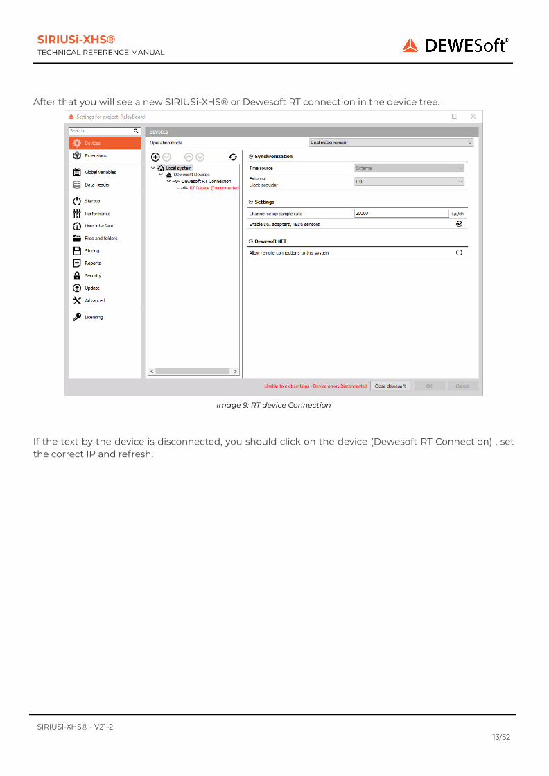
3.5.1. Power in connector
Power in connector: pin-out (2-pin LEMO male)
Pin Name Description
1 V + Supply
2 V - Ground
Power In connector (on the device): EXJ.1B.302.CLAMating connector (for the cable): FGJ.1B.302.CLLD52Z
3.5.1.1. Power out connector
Power out connector: pin-out (2-pin LEMO female)
Pin Name Description
1 V+ Supply
2 V- Ground
Power Out connector (on the device): EXG.1B.302.CLLMating connector (for the cable): FGG.1B.302.CLAD52Z
The Power Out power plug can be used to daisy-chain several devices together.Daisy chain cable: L1B2m-L1B2f
SIRIUSi-XHS® - V21-229/52

SIRIUSi-XHS®TECHNICAL REFERENCE MANUAL
3.5.2. SYNC connector
The sync connectors are required when you want to use multiple SIRIUSi-XHS®® USB slices for thesame measurement. The signal that is transferred over this cable makes sure that the measurementdata of the different slices are perfectly synchronized to each other.
Sync connector: pin-out (4-pin LEMO female)
Pin Name Description
1 CLK Clock
2 Trigg Trigger
3 GPS-PPS GPS - PPS
4 DGND Digital Ground
Interface connector: EEG.00.304.CLLMating connector: FGG.00.304.CLAD27Z
ImportantWhen IRIG-synchronisation is used, the IRIG differential signals are on pins 1, 2.When Clock / Trigger is used, the signals are on pins 1, 2.When PPS-GPS synchronization is used, the PPS signal is on pin 3.
3.5.3. CANA Controller Area Network (CAN bus) is a vehicle bus standard often used in automotive applications.SIRIUS slices usually have a CAN connector on the back side, while Rack version on the front side.
SIRIUSi-XHS® - V21-230/52

SIRIUSi-XHS®TECHNICAL REFERENCE MANUAL
CAN connector: pin-out (DSUB-9 male)
Pin Name Description
1 RES Reserved
2 CAN_LOW CAN low
3 DGND Digital Ground
4 RES Reserved
5 +5 V 5 V, 100 mA supply
6 RES Reserved
7 CAN_HIGH CAN high
8 RES Reserved
9 RES Reserved
3.5.4. GND connectorFor correct measurements, it is highly recommended to ground the SIRIUS®. The GND connector isusually a banana connector. There may also be a screw connector: e.g. SIRIUS-R8.
WarningIt is mandatory to connect a ground cable to the GND connector when you are working with highvoltages: e.g. when you are working with the HV modules.
ImportantCAN transmit is currently not supported, therefore all the plugins that require CAN transmit donot work property (e.g. OBD2, XCP)
SIRIUSi-XHS® - V21-231/52

SIRIUSi-XHS®TECHNICAL REFERENCE MANUAL
3.5.5. Ethernet ConnectorConnector used on the device is a standard ethernet connector (RJ45).Standard ethernet cable with standard connector can be used to connect SIRIUSi-XHS® with a PC.
GLAN connector: pin-out (RJ-45 female)
Pin Name Description
1 Tx A+ Transmitting pair A+
2 Tx A- Transmitting pair A-
3 Rx B+ Receiving pair B+
4 Tx C+ Transmitting pair C+
5 Tx C- Transmitting pair C-
6 Rx B- Receiving pair B-
7 Rx D+ Receiving pair D+
8 Rx C- Receiving pair C-
3.5.6. USB connectorUSB 3.0 has a maximum signalling rate of 625 Mbit/s (High Speed or High Bandwidth).
The Illustrations to the right show a USB-C and Standard size USB sockets.
Image 51: USB-C connector on the device and USB connector on the PC, SBOX
SIRIUSi-XHS® - V21-232/52

SIRIUSi-XHS®TECHNICAL REFERENCE MANUAL
4. Module overviewCurrently HV, LV and ACC amplifierts are supported on the SIRIUSi-XHS® device.
XHS-HV XHS-LV XHS-ACC
Connectors BANANA DB9, BNC BNC
Channels per slice 8
Data rate / channel 15 MS/s
Resolution 16-bit (24-bit @ 1 MS/s)
Bandwidth 5 MHz
Voltage ranges ±2000 V ... ±200 V ±100 V ... ±50 mV ±10 V ... ±200 mV
Input coupling DC DC, AC 1 Hz DC, AC 0.1 Hz, AC 1 Hz
Sensor excitation -2.5..30 V bipolar, 2..24 V unipolar, max.
0.2 A / 2 WIEPE 2 mA, 4 mA, 8 mA,
12 mA, 16 mA, 20 mA
Bridge connection - Full -
Programmable shunt - - -
IEPE input - DSI-ACC ✓
Resistance - - -
Temperature (PTx) - DSI-RTD -
Thermocouple - DSI-TH -
Potentiometer - - -
LVDT - DSI-LVDT -
Charge - DSI-CHG -
Current -ext. shunt
DSI20mA, DSI5A ext. shunt
TEDS - ✓ ✓
Isolation voltage CATII 1000 V 1000 V 1000 V
Power consumption perchannel 1 W/ch 1.2 W/ch TBD
Advanced functionsHigh voltage, high bandwidth,
high isolation High sensor excitation and multi rangeSensor error detection,
high speed
Rev: 1610438400
SIRIUSi-XHS® - V21-233/52

SIRIUSi-XHS®TECHNICAL REFERENCE MANUAL
4.1. SIRIUSi-XHS® dimensions
Image 52: Dimensions
SIRIUSi-XHS® - V21-234/52

SIRIUSi-XHS®TECHNICAL REFERENCE MANUAL
4.2. HV: SpecificationsThe HV modules are perfect for high voltage measurements.
Inputs Voltage
ADC Type Hybrid ADC - 24-bit alias free up to 1 MS/s, 16-bit up to 15 MS/s
Sampling Rate Simultaneous 15 MS/s
Filtering AAF 1 MHz (6th order)
Analogue bandwidth (-3 dB) 5 MHz
Voltage ranges ±2000 V, ±1000 V, ±400 V, ±200 V
Input Accuracy
Signal frequency Accuracy
DC to 1 kHz ±0.03 % of reading ±0.02 % of range
Up to 10 kHz ±0.1 % of reading ±0.05 % of range
Up to 100 kHz ±4 % of reading ±0.1 % of range
Up to 1000 kHz ±5 % of reading ±0.5 % of range
Noise floor, Typ.
Sample rate / Range → 2000 V 1000 V 400 V 200 V
15 MS/s -84 dB -82 dB -79 dB -75 dB
1 MS/s -95 dB -93 dB -85 dB -78 dB
100 kS/s -108 dB -106 dB -100 dB -95 dB
10 kS/s -117 dB -115 dB -109 dB -104 dB
CMR, Typ. 101 dB @ 50 Hz, 74 dB @ 400 Hz
Channel Crosstalk -116 dB typ. @ 50 Hz, -89 dB typ. @ 1 kHz
Gain Drift Typical 20 ppm/K, max. 40 ppm/K
Offset Drift Typical 1.5 mV/K + 1 ppm of range/K, max 3 mV/K + 2 ppm of range/K
Gain Linearity < 0.01 %
Input Coupling DC
Input Impedance 10 MΩ || 1 pF
Protection class CAT III 600 V; CAT II 1000 V
Additional Specifications
Input connector Banana
Rev: 1612519200
SIRIUSi-XHS® - V21-235/52
SIRIUSi-XHS®TECHNICAL REFERENCE MANUAL
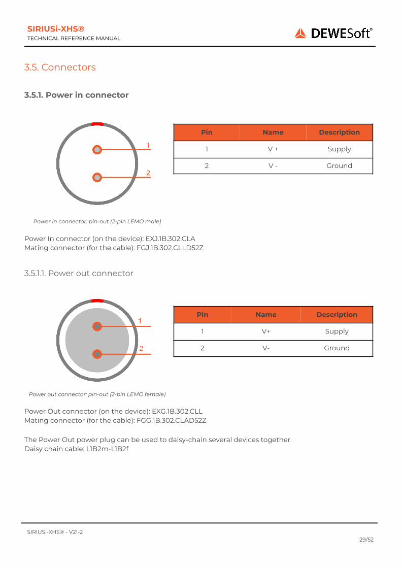
4.2.2. HV- Banana Connector
HV connector: pin-out (Banana plug)
SIRIUSi-XHS®-8xHV
WarningIt is mandatory to connect a ground cable to the GND connector of the SIRIUS® when you areworking with high voltages.
4.2.2. HV: Voltage
SIRIUSi-XHS® - V21-236/52

SIRIUSi-XHS®TECHNICAL REFERENCE MANUAL
4.3. LV: SpecificationsThe LV modules are perfect for low voltage and current measurements in combination with currentclamps.
Inputs Voltage
ADC Type Hybrid ADC - 24-bit alias free up to 1 MS/s, 16-bit up to 15 MS/s
Sampling Rate Simultaneous 15 MS/s
Filtering AAF 1 MHz (6th order)
Analog bandwidth (-3 dB) 5 MHz
Voltage ranges ±100, 50, 20, 10, 5, 2, 1, 0.5, 0.2, 0.1 and 0.05 V
Input Accuracy
DC±0.03 % of reading ±0.02 % of range ±100 μV (2 mV for Ranges ≥ 10V)
Up to 1 kHz ±0.03 % of reading ±0.02 % of range
Up to 10 kHz ±0.1 % of reading ±0.05 % of range
Up to 100 kHz ±2 % of reading ±0.1 % of range
Up to 1000 kHz ±5 % of reading ±0.5 % of range
Noise floor, Typ.
Sample rate, filter \ Range → 100 V 5 V 0.5 V
15 MS/s, Filter off -82 dB -78 dB -65 dB
1 MS/s, Filter on -94 dB -95 dB -88 dB
100 kS/s, Filter on -104 dB -105 dB -100 dB
10 kS/s, Filter on -113 dB -114 dB -107 dB
CMR, Typ.
Frequency \ Range → 100 V 5 V 0.5 V
50 Hz 91 dB 102 dB 98 dB
400 Hz 86 dB 75 dB 90 dB
10 kHz 66 dB 74 dB 82 dB
Channel CrosstalkRange ≥ 10 V: -105 dB @ 10 kHzRange < 10 V: -120 dB @ 10 kHz
Gain Drift Typical 10 ppm/K, max. 30 ppm/K
Offset DriftRange ≥ 10 V: Typ. 100 μV/K + 1 ppm of range/K, Max 250 μV/K + 2 ppm of range/KRange < 10 V: Typ. 4 μV/K + 1 ppm of range/K, Max 8 μV/K + 2 ppm of range/K
Gain Linearity < 0.03 %
Input Coupling (see 1) DC, AC 1 Hz (3 Hz, 10 Hz per SW)
Input Impedance Range < 10 V: 10 MΩ; Range ≥ 10 V: 1 MΩ || 110 pF between INx to GND
Excitation Voltage Unipolar or Bipolar Software selectable (programmable 16-bit DAC)
Excitation Level unipolar 2 .. 24 V; Predefined levels: 2, 2.5, 5, 10, 12, 15, 20 and 24 VDC
Excitation Level bipolar 2.5 .. 30 V; Predefined levels: 2.5, 5, 10, 12, 15, 24 and 30 VDC
Drift ±10 ppm/K ±150 μV/K
Stability 10% to 90% load(bipolar) < 0.01 %
Current limit 200 mA (2 Watt max. per Channel, 12 Watt max. per Slice)
Additional Specifications
Input connector DSUB 9, BNC (others on request)
SIRIUSi-XHS® - V21-237/52

SIRIUSi-XHS®TECHNICAL REFERENCE MANUAL
TEDS support Standard + DSI® adapters
Rev: 1617026400
1) In- must be within ±10V referred to GND(iso); for Ranges ≥ 10 V the DC value of In- is not rejected
4.3.1. LV: DSUB connector
LV connector: pin-out (DSUB-9 female)
SIRIUSi-XHS®-8xLV
4.3.1.1. LV: VoltageSingle ended Differential
SIRIUSi-XHS® - V21-238/52

SIRIUSi-XHS®TECHNICAL REFERENCE MANUAL
4.3.1.2. LV: Current
4.3.2. LV: BNC connector
LV-BNC connector: pin-out (BNC)SIRIUSi-XHS®-8xLV-BNC
SIRIUSi-XHS® - V21-239/52

SIRIUSi-XHS®TECHNICAL REFERENCE MANUAL
4.4. ACC: Specifications
The ACC modules are perfect for sound and vibration IEPE channels.
Inputs
Input typesVoltageIEPE
ADC Type Hybrid ADC - 24-bit alias free up to 1 MS/s, 16-bit up to 15 MS/s
Sampling Rate Simultaneous 15 MS/s
Filtering AAF 1 MHz (6th order)
Analogue bandwidth (-3 dB) 5 MHz
Voltage ranges ±10, 5, 2, 1, 0.4 and 0.2 V
Input Accuracy
DC ±0.03 % of reading ±0.02 % of range ±50 μV
Up to 1 kHz ±0.04 % of reading ±0.02 % of range
Up to 10 kHz ±0.06 % of reading ±0.05 % of range
Up to 100 kHz ±0.1 % of reading ±0.1 % of range
Up to 1000 kHz ±5 % of reading ±0.5 % of range
Noise floor, Typ. Sample rate,filter \ Range → 10 V 5 V 2 V 1 V 0.4 V
15 MS/s, Filteroff -88 dB -88 dB -88 dB -87 dB -76 dB
1 MS/s, Filter on -99 dB -99 dB -97 dB -95 dB -92 dB
100 kS/s, Filteron -109 dB -107 dB -108 dB -107 dB -103 dB
10 kS/s, Filteron -120 dB -120 dB -119 dB -118 dB -114 dB
CMR, Typ. (Min) Frequency \Range → 10 V 5 V 2 V 1 V 0.4 V
50 Hz 141 dB 141 dB 139 dB 133 dB 121 dB
400 Hz 130 dB 133 dB 136 dB 137 dB 137 dB
1 kHz 122 dB 125 dB 127 dB 129 dB 130 dB
Gain Drift Typical 10 ppm/K, max. 30 ppm/K
Offset Drift Typical 0.5 μV/K + 1 ppm of range/K, max. 2 μV/K + 4 ppm of range/K
Gain Linearity < 0.02 %
Inter ChannelPhase-mismatch 0.005° * fin [kHz] + 0.0002°
Channel Cross talk -145 dB typ. @ 1 kHz
Input Coupling DC or AC (1 Hz, 0.1 Hz)
Input Impedance 1 MΩ
Overvoltage Protection 50 V continuous; 200 V peak (10 msec)
IEPE mode
Excitation 2 mA, 4 mA, 8 mA, 12 mA, 16 mA, 20 mA
Compliance voltage 24 V
Output Impedance > 10 kΩ
SIRIUSi-XHS® - V21-240/52

SIRIUSi-XHS®TECHNICAL REFERENCE MANUAL
Sensor detection Shortcut: < 4 V; Open: > 19 V
Additional Specifications
Input connector BNC
TEDS support IEPE mode only
Rev: 1615795200
4.4.1. ACC: BNC connector
ACC connector: pin-out (BNC)
SIRIUSi-XHS®-8xACC
4.4.1.1. ACC: Voltage, IEPE
Voltage IEPE
SIRIUSi-XHS® - V21-241/52

SIRIUSi-XHS®TECHNICAL REFERENCE MANUAL
5. Real-time controller - XCP slave settingsWith the SIRIUSi-XHS® device, data can be run in parallel over the XCP protocol, when the device isconnected in Run-time mode over Ethernet. Follow the instructions written in chapter 2.2.3.DewesoftX® settings for SIRIUSi-XHS®, to properly connect and set the device.
The XCP settings must be specified in Dewesoft software and properly uploaded to the device. Whenthe settings are done and the RT-mode is properly started, Dewesoft can be closed. The maximumsample rate for data transmitted over the XCP protocol is 1Mhz.
5.1. XCP-Slave module settings
The Real-time controller module is added in the Channel setup the same way as any other module. Ifthe module can not be selected, you need to re-check in settings if the RT device is properly configuredand recognized.
Image 53: Adding RT controller module
When you enter the Module the following settings will appear. If multiple RT devices are connected, aseparate tab will be created for each one❶ .
SIRIUSi-XHS® - V21-242/52

SIRIUSi-XHS®TECHNICAL REFERENCE MANUAL
Image 54: RT controller module settings
5.1.1. XCP output settings❷To enable the XCP output the “Enable XCP output” check-box needs to be ticked, otherwise no data willbe transmitted.
With the current version of XCP slave only the TCP/IP transport layer is supported, so therefore only thisoption can be chosen from the drop-down list.
Re-check that the IP address is static and that matches the IP address of the connected RT device.
Under the port setting you can set on which port the XCP slave will open the connection. The defaultsetting is 5555.
5.1.2. XCP Event settings❸The XCP Event settings will be recalculated from the chosen dynamic acquisition rate, that is set in theAnalog In tab.. Time unit is defined as time between two samples. The Time Cycle is a divider that isneeded to reach the actual time unit.
ExampleWhen 100kHz SR is chosen, the time unit is 10us and the Time Cycle is 1. When we increase theSR to 200kHz, the Time unit is 1us and the Time Cycle is therefore 5.
When a Time cycle is not a rounded number, the XCP module will give you a warning.
SIRIUSi-XHS® - V21-243/52

SIRIUSi-XHS®TECHNICAL REFERENCE MANUAL
Image 55: Incorrect divider
ImportantThe maximum sample rate that can be used with the XCP module is 1 MHz. When a highersample rate is chosen the module will pop-out the warning.
Image 55: Incorrect sample rate
5.1.3. XCP outputs (channels)❹This section is for setting up the XCP outputs. Here you can just click the Auto-Generatebutton, which will populate the list with all available device channels, which are set to used(you can set them to USED under Analog in).
Image 56: Generated AI channels
If the channels will be changed to UNUSED under the Analog Input module, the XCP slave willrecognize those channels and will mark them in red.
SIRIUSi-XHS® - V21-244/52

SIRIUSi-XHS®TECHNICAL REFERENCE MANUAL
5.1.4. Generating A2L file❺When you are done with the previous steps you can export all XCP slave settings to A2L file,by clicking the Generate A2L button. If you modified any of the settings you will be prompted to rebuildand upload XCP settings to the device. It’s important that you click yes.
Image 57: Rebuild and upload warning
5.1.5. Download and Upload button❻When you properly set the settings you can press the Upload button, which will upload all the settingsdirectly to the device. An additional Download button is added, that can “Read” the settings directlyfrom the device, once they are properly uploaded.
5.2. Start the XCP protocolWhen all the settings are set the device needs to be put in the RT mode, for that you need to pressSTART button❼. After start you can connect to XCP slave via XCP master (e.g. Dewesoft, Canape). If you
want to start all the RT devices at once press the Start all button❽.
There is also an additional option Restart acquisition on device startup , for setting the device directlyto RT-mode right away the device is reconnected back to power supply. For this option to work properly,the device needs to be in the RT mode when unplugged from the power supply.
Image 58: Restart acquisition on device startup
SIRIUSi-XHS® - V21-245/52

SIRIUSi-XHS®TECHNICAL REFERENCE MANUAL
6. Troubleshooting6.1. Device not recognized when connected over USBWhen the device is connected over the USB an additional Ethernet network card is created. If the USBdevice is not seen in Dewesoft the user needs to disable the Opto Stream drivers in the Ethernetnetwork card.
Opto Stream drivers disabled
6.2. Clear static configurationIn any case that the device got stuck in channel setup and the user can not proceed to measure mode ,you can clear all the configuration from the device with the “clear static configuration” button that canbe found in Device settings.
Clear static configuration button
SIRIUSi-XHS® - V21-246/52

SIRIUSi-XHS®TECHNICAL REFERENCE MANUAL
7. Safety instructions
Your safety is our primary concern! Please be safe!
7.1. General Safety Instructions
Warning
The following general safety precautions must be observed during all phases of operation, service, andrepair of this product. Failure to comply with these precautions or with specific warnings elsewhere inthis manual violates safety standards of design, manufacture, and intended use of the product.Dewesoft d.o.o. assumes no liability for the customer’s failure to comply with these requirements.
All accessories shown in this document are available as an option and will not be shipped as standardparts.
7.1.1. Environmental ConsiderationsInformation about the environmental impact of the product.
7.1.2. Product End-of-Life HandlingObserve the following guidelines when recycling a Dewesoft system:
System and Components RecyclingProduction of these components required the extraction and use of natural resources. The substancescontained in the system could be harmful to your health and to the environment if the system isimproperly handled at its end of life! Please recycle this product in an appropriate way to avoid anunnecessary pollution of the environment and to keep natural resources.
This symbol indicates that this system complies with the European Union’s requirementsaccording to Directive 2002/96/EC on waste electrical and electronic equipment (WEEE).Please find further information about recycling on the Dewesoft web sitewww.dewesoft.com
Restriction of Hazardous SubstancesThis product has been classified as Monitoring and Control equipment and is outside the scope of the2002/95/EC RoHS Directive. However, we take care of our environment and the product is lead-free.
7.1.3. General safety and hazard warnings for all Dewesoft systemsSafety of the operator and the unit depend on following these rules.
● Use this system under the terms of the specifications only to avoid any possible danger.
SIRIUSi-XHS® - V21-247/52

SIRIUSi-XHS®TECHNICAL REFERENCE MANUAL
● Read your manual before operating the system.● Observe local laws when using the instrument.● DO NOT touch internal wiring!● DO NOT use higher supply voltage than specified!● Use only original plugs and cables for harnessing.● You may not connect higher voltages than rated to any connectors.● The power cable and connector serve as Power-Breaker. The cable must not exceed 3 meters, the
disconnect function must be possible without tools.● Maintenance must be executed by qualified staff only.● During the use of the system, it might be possible to access other parts of a more
comprehensive system. Please read and follow the safety instructions provided in the manuals ofall other components regarding warning and security advice for using the system.
● With this product, only use the power cable delivered or defined for the host country.● DO NOT connect or disconnect sensors, probes or test leads, as these parts are connected to a
voltage supply unit.● Ground the equipment: For Safety Class 1 equipment (equipment having a protective earth
terminal), a non-interruptible safety earth ground must be provided from the mains powersource to the product input wiring terminals.
● Please note the characteristics and indicators on the system to avoid fire or electric shocks.Before connecting the system, please read the corresponding specifications in the productmanual carefully.
● The inputs must not unless otherwise noted (CATx identification), be connected to the mainscircuit of category II, III and IV.
● The power cord separates the system from the power supply. Do not block the power cord, sinceit has to be accessible for the users.
● DO NOT use the system if equipment covers or shields are removed.● If you assume the system is damaged, get it examined by authorized personnel only.● Adverse environmental conditions are Moisture or high humidity Dust, flammable gases, fumes
or dissolver Thunderstorm or thunderstorm conditions (except assembly PNA) Electrostaticfields, etc.
● The measurement category can be adjusted depending on module configuration.● Any other use than described above may damage your system and is attended with dangers like
short-circuiting, fire or electric shocks.● The whole system must not be changed, rebuilt or opened.● DO NOT operate damaged equipment: Whenever it is possible that the safety protection
features built into this product have been impaired, either through physical damage, excessivemoisture, or any other reason, REMOVE POWER and do not use the product until the safeoperation can be verified by service-trained personnel. If necessary, return the product toDewesoft sales and service office for service and repair to ensure that safety features aremaintained.
● If you assume a more riskless use is not provided anymore, the system has to be renderedinoperative and should be protected against inadvertent operation. It is assumed that a moreriskless operation is not possible anymore if the system is damaged obviously or causes strangenoises. the system does not work anymore. the system has been exposed to long storage inadverse environmental. the system has been exposed to heavy shipment strain.
● Warranty void if damages caused by disregarding this manual. For consequential damages, NOliability will be assumed!
● Warranty void if damage to property or persons caused by improper use or disregarding thesafety instructions.
SIRIUSi-XHS® - V21-248/52

SIRIUSi-XHS®TECHNICAL REFERENCE MANUAL
● Unauthorized changing or rebuilding the system is prohibited due to safety and permissionreasons (CE).
● Be careful with voltages >25 VAC or >35 VDC! These voltages are already high enough in order toget a perilous electric shock by touching the wiring.
● The product heats during operation. Make sure there is adequate ventilation. Ventilation slotsmust not be covered!
● Only fuses of the specified type and nominal current may be used. The use of patched fuses isprohibited.
● Prevent using metal bare wires! Risk of short circuit and fire hazard!● DO NOT use the system before, during or shortly after a thunderstorm (risk of lightning and high
energy over-voltage). An advanced range of application under certain conditions is allowed withtherefore designed products only. For details, please refer to the specifications.
● Make sure that your hands, shoes, clothes, the floor, the system or measuring leads, integratedcircuits and so on, are dry.
● DO NOT use the system in rooms with flammable gases, fumes or dust or in adverseenvironmental conditions.
● Avoid operation in the immediate vicinity of high magnetic or electromagnetic fields,transmitting antennas or high-frequency generators, for exact values please refer to theenclosed specifications.
● Use measurement leads or measurement accessories aligned with the specification of thesystem only. Fire hazard in case of overload!
● Do not switch on the system after transporting it from a cold into a warm room and vice versa.The thereby created condensation may damage your system. Acclimatise the system unpoweredto room temperature.
● Do not disassemble the system! There is a high risk of getting a perilous electric shock.Capacitors still might be charged, even if the system has been removed from the power supply.
● The electrical installations and equipment in industrial facilities must be observed by the securityregulations and insurance institutions.
● The use of the measuring system in schools and other training facilities must be observed byskilled personnel.
● The measuring systems are not designed for use in humans and animals.● Please contact a professional if you have doubts about the method of operation, safety or the
connection of the system.● Please be careful with the product. Shocks, hits and dropping it from already- lower level may
damage your system.● Please also consider the detailed technical reference manual as well as the security advice of the
connected systems.● This product has left the factory in safety-related flawless and in proper condition. In order to
maintain this condition and guarantee safety use, the user has to consider the security adviceand warnings in this manual.
SIRIUSi-XHS® - V21-249/52

SIRIUSi-XHS®TECHNICAL REFERENCE MANUAL
8. NoticeThe information contained in this document is subject to change without notice.
Note:Dewesoft d.o.o. shall not be liable for any errors contained in this document. Dewesoft MAKES NOWARRANTIES OF ANY KIND WITH REGARD TO THIS DOCUMENT, WHETHER EXPRESS OR IMPLIED.DEWESOFT SPECIFICALLY DISCLAIMS THE IMPLIED WARRANTIES OF MERCHANTABILITY ANDFITNESS FOR A PARTICULAR PURPOSE. Dewesoft shall not be liable for any direct, indirect, special,incidental, or consequential damages, whether based on contract, tort, or any other legal theory, inconnection with the furnishing of this document or the use of the information in this document.
8.1. Warranty InformationThe copy of the specific warranty terms applicable to your Dewesoft product and replacement parts canbe obtained from your local sales and service office. To find a local dealer for your country, please visithttps://dewesoft.com/support/distributers.
8.2. CalibrationEvery instrument needs to be calibrated at regular intervals. We recommend annual calibration. Beforeyour Dewesoft data acquisition system is delivered, it is calibrated. Detailed calibration reports for yourDewesoft system can be requested. We retain them for at least one year, after system delivery.
8.3. SupportDewesoft has a team of people ready to assist you if you have any questions or any technical difficultiesregarding the system. For any support please contact your local distributor first or Dewesoft directly.
E-mail: [email protected]
Address:Dewesoft d.o.o.Gabrsko 11a1420 Trbovlje Slovenia
Europe Tel.: +386 356 25 300Web: http://www.dewesoft.comThe telephone hotline is available Monday to Friday from 07:00 to 16:00 CET (GMT +1:00)
8.4. Service/repairThe team of Dewesoft also performs any kinds of repairs to your system to assure a safe and properoperation in the future. For information regarding service and repairs please contact your localdistributor first or Dewesoft directly on https://dewesoft.com/support/rma-service.
8.5. Restricted RightsUse Slovenian law for duplication or disclosure. Dewesoft d.o.o. Gabrsko 11a, 1420 Trbovlje, Slovenia /Europe.
SIRIUSi-XHS® - V21-250/52

SIRIUSi-XHS®TECHNICAL REFERENCE MANUAL
8.6. Printing HistoryVersion 1.0.0Released 2020Last changed: 13/05/2019 at 12:00.
8.7. CopyrightCopyright © 2015-2020 Dewesoft d.o.o.
This document contains information which is protected by copyright. All rights are reserved.Reproduction, adaptation, or translation without prior written permission is prohibited, except asallowed under the copyright laws.
All trademarks and registered trademarks are acknowledged to be the property of their owners.
8.8. TrademarksWe take pride in our products and we take care that all key products and technologies are registered astrademarks all over the world.The Dewesoft name is a registered trademark.Product families (KRYPTON, SIRIUS, DSI, DS-NET, IOLITE) and technologies (DualCoreADC,SuperCounter, GrandView) are registered trademarks as well.When used as the logo or as part of any graphic material, the registered trademark sign is used as a partof the logo.When used in text representing the company, product or technology name, the ® sign is not used. TheDewesoft triangle logo is a registered trademark but the ® sign is not used in the visual representationof the triangle logo.
SIRIUSi-XHS® - V21-251/52

SIRIUSi-XHS®TECHNICAL REFERENCE MANUAL
8.9. Documentation version
Doc-Version Date[dd.mm.yyyy]
Notes
V21-2 4.4.2021 License on the device, additional
V20-1 18.1.2021 Added XCP opton, Few small fixes
V20-1 13.05.2020 Initial version
SIRIUSi-XHS® - V21-252/52