Embed Size (px)
Citation preview
Introduction .......................................................................... 1
System Overview................................................................. 3
Setting up a Tri-GP System ............................................... 13
Product Specifications ....................................................... 17
Communication Capabilities .............................................. 43
TriStation 1131 Developer’s Workbench ........................... 45
CEM Programming Language Editor................................. 49
Sequence of Events (SOE) Capability............................... 51
Glossary............................................................................. 53
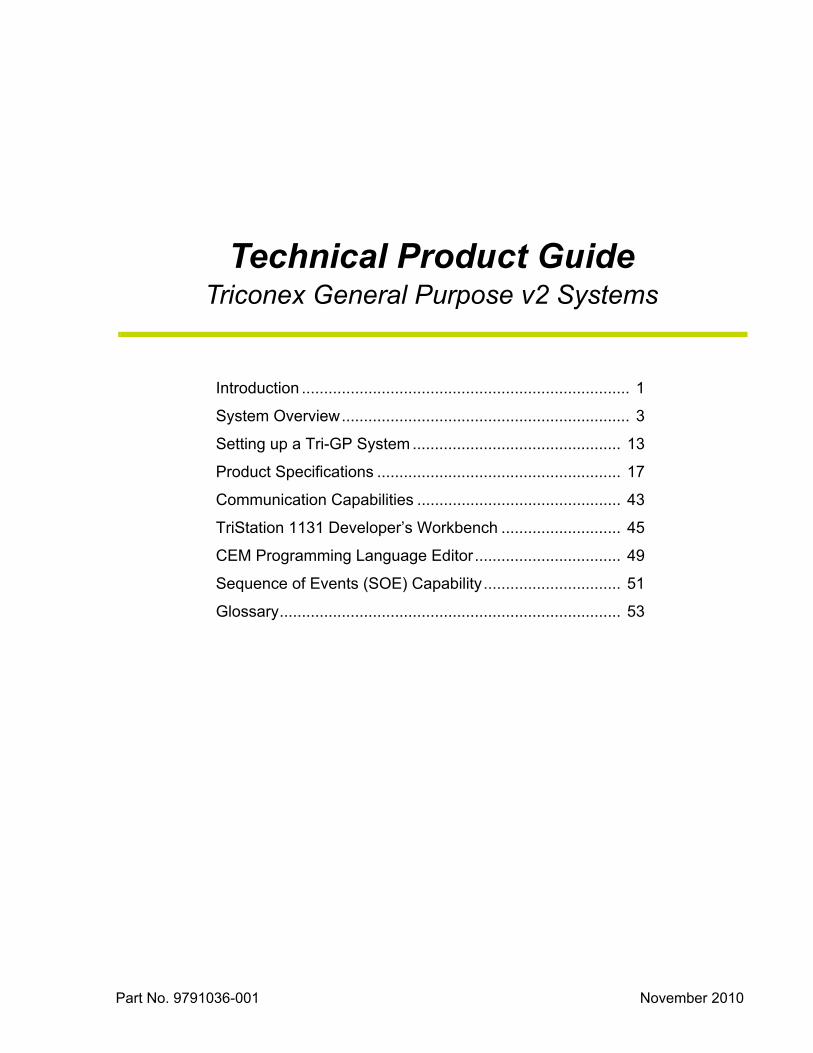
Technical Product GuideTriconex General Purpose v2 Systems
Part No. 9791036-001 November 2010

Information in this document is subject to change without notice. Companies, names and data used in examples herein are fictitious unless otherwise noted. No part of this document may be reproduced or transmitted in any form or by any means, electronic or mechanical, for any purpose, without the express written permission of Invensys Systems, Inc.
© 2010 by Invensys Systems, Inc. All rights reserved.
Invensys, the Invensys logo, Triconex, Tricon, Trident, and TriStation are trademarks of Invensys plc, its subsidiaries and affiliates. All other brands may be trademarks of their respective owners.
DISCLAIMER
Because of the variety of uses for this equipment and because of the differences between this fault-tolerant equipment and traditional programmable logic and process controllers, the user of, and those responsible for applying, this equipment must satisfy themselves as to the acceptability of each application and the use of the equipment.
The illustrations, charts and layout examples shown in this manual are intended solely to illustrate the text of this manual. Because of the many variables and requirements associated with any particular installation, Invensys Systems, Inc. cannot assume responsibility or liability for actual use based upon the illustrative uses and applications.
In no event will Invensys Systems, Inc. be responsible or liable for indirect or consequential damages resulting from the use or application of this equipment.
INVENSYS SYSTEMS, INC. DISCLAIMS ANY IMPLIED WARRANTY OF FITNESS FOR A PARTICULAR PURPOSE.
Invensys Systems, Inc. reserves the right to make changes at any time in order to improve design and to supply the most reliable product. No patent or copyright liability is assumed by Invensys Systems, Inc. with respect to use of information, circuits, equipment or software described in this text.
TECHNICAL SUPPORT
Customers in the U.S. and Canada can obtain technical support from the Invensys Global Customer Support (GCS) center at the numbers below. International customers should contact their regional support center.
Telephone: Toll-free number 866-746-6477Toll number 508-549-2424 (outside U.S.)
Fax: Toll number 508-549-4999
E-mail: [email protected]
Preface

1
The Tri‐GP controller is state‐of‐the art and provides fault tolerance by means of Triple‐Modular Redundant (TMR) architecture.
Introduction
What is Fault-Tolerant Control?
Fault-tolerance in a control system identifies and compensates for failed system elements and allows repair while continuing to control an indus-trial process without interruption. A high-integrity control system such as the Triconex® General Purpose (Tri-GP) controller can be used in crit-ical process applications that require a significant degree of safety and avail-ability.
What is the Tri-GP Controller?
The Tri-GP controller is a state-of-the art programmable logic controller that provides fault tolerance by means of Triple-Modular Redundant (TMR) architecture. TMR integrates three isolated, parallel control systems and extensive diagnostics in one control system. The system uses two-out-of-three voting to provide high-integrity, error-free, uninterrupted process opera-tion with no single point of failure.
The Tri-GP controller uses three iden-tical channels. Each channel indepen-dently executes the application in parallel with the other two channels. Specialized hardware and software voting mechanisms qualify and verify all digital inputs and outputs from the field, while analog inputs are subject to a mid-value selection process.
Because each channel is isolated from the others, no single-point failure in any channel can pass to another. If a hard-ware failure occurs on one channel, the other channels override it. Meanwhile, the faulting module can be easily removed and replaced while the controller is online without interrupting the process.
Setting up applications is simplified with the triplicated Tri-GP system, because it operates as a single control system from a customer’s point of view. You can terminate sensors and actua-
tors at a single wiring terminal and program the Tri-GP controller with one set of application logic. The Tri-GP controller manages the rest.
Tri-GP System Mounted on a Panel

2
Introduction
Extensive diagnostics on each channel, module, and functional circuit immedi-ately detect and report operational faults by means of indicators or alarms. All diagnostic fault information is accessible to the application and the operator. This diagnostic data can be used to modify control actions or to direct maintenance procedures.
Other features of the Tri-GP controller that ensure the highest possible system integrity include:
• Ability to withstand harsh industrial environments.
• Optimized for applications with small to medium point counts.
• Support for remote and distributed I/O.
• Wall- or skid-mounting outside of control room and enclosures.
• Version 2.x supports 25 total I/O Baseplates.
• Hot-spare I/O modules for critical applications where prompt attention from the operator is not possible.
• Integral support for redundant field power and logic power sources.
• Integration of I/O modules with field termination assemblies.
• Field installation and repair at the module level while the controller remains online and without disturbing field wiring
• Execution of applications developed and debugged using the TriStation™ 1131 Developer’s Workbench.
• TriStation 1131 and Modbus communication from the Main Processors.
What are Typical User-Created Applications?Each day Tri-GP systems supply increased safety, reliability, and avail-ability to a worldwide installed base. The following sections describe typical applications. For details on the value Tri-GP can bring to your applications, ask your sales representative for addi-tional documentation and customer references.
Emergency Safety Shutdown (ESD)
Tri-GP controllers provide continuous protection for safety-critical units in refineries, petrochemical and chemical plants, and other industrial processes. For example, in reactor and compressor units, plant trip signals—for pressure, product feed rates, expander pressure equalization and temperature—are monitored and shutdown actions taken if an upset condition occurs. Traditional shutdown systems implemented with mechanical or electronic relays may provide shutdown protection, but can also cause dangerous nuisance trips.
Boiler Flame Safety
Process steam boilers are a critical component in most refinery applica-tions. Protection of the boiler from upset conditions, safety interlock for normal startup and shutdown, and flame-safety applications are combined in one integrated Tri-GP system.
In traditional applications, these func-tions are provided by separate, non-integrated components. With the fault-tolerant, fail-safe Tri-GP controller, the boiler operations staff can use a critical resource more productively while maintaining safety at or above the level of electromechanical protection systems.
What is TriStation 1131 Developer's Workbench?The TriStation 1131 Developer's Work-bench is an integrated tool for devel-oping, testing, and documenting applications for the Tri-GP controller. The programming methodology, user interface, and self-documentation capa-bilities make TriStation 1131 software superior to traditional and competing engineering tools. TriStation 1131 soft-ware complies with Part 3 of the IEC 61131 International Standard for Programmable Controllers and follows the Microsoft® Windows® guidelines for graphical user interfaces.
What about Communication Capabilities?The Tri-GP controller provides communication capabilities through ports on the Main Processor and Communication Modules.
Ports on the MP support Modbus slave and TriStation 1131 protocols.
Ports on the CM support:
• Modbus slave (ASCII or RTU)
• Modbus master (RTU)
• Modbus master or slave (TCP)
• TriStation 1131 software
• TCP/IP
• TSAA (UDP/IP)
• TSAA with IP multicast (UDP/IP)
• Triconex Time Synchronization (DLC, UDP/IP, or SNTP)
• Triconex Peer-to-Peer (DLC or UDP/IP)
• HP JetDirect® (DLC/LLC)
The Communication Baseplate can contain one or two CM Modules.
For more information, see page 43.

3
The Tri‐GP controller is designed with a fully triplicated architecture throughout, from the input modules through the Main Processors to the output modules.
System Overview
Fault tolerance in the Tri-GP controller is achieved through the Triple Modular Redundant (TMR) architecture. The Tri-GP provides error-free, uninter-rupted control in the event of hard fail-ures of components or transient faults from internal or external sources.
The Tri-GP is designed with a fully triplicated architecture throughout, from the input modules through the Main Processors (MPs) to the output modules. Each module houses the circuitry for three independent chan-nels. Each channel on an input module reads the process data and passes it to the corresponding MP. The three MPs communicate with each other using a proprietary, high-speed bus called the TriBus.
Once per scan, the MPs synchronize and communi-cate with their neighbors over the TriBus. The TriBus sends copies of all analog and digital input data to each MP, then compares output data from each MP. The MPs vote the input data, execute the application, and send outputs generated by the application to the output modules.
In addition, the Tri-GP controller votes the output data on the output modules as close to the field as possible. This allows the Tri-GP to detect and compensate for any errors that could occur between the TriBus voting and the final output driven to the field.
Each I/O Baseplate supports two modules in one logical slot which means both the active and hot-spare module receive the same information from the field termination wiring.
The Main Processors switch control between the two healthy I/O modules approximately every hour, so that each module undergoes complete diagnos-tics on a regular basis.
If a fault is detected on the active module, Tri-GP automatically switches control to the hot-spare module, allowing the system to continuously work in triplicated control. The faulty module can then be removed and replaced. For details, see “Online Module Repair” on page 11.
Main Processor Module
Every Tri-GP system contains three Main Processors. Each MP controls a separate channel and operates in parallel with the other two MPs.
A dedicated I/O control processor on each MP manages the data exchanged between the MP and the I/O modules. A triplicated I/O bus, located on the base-plates, extends from one column of I/O modules to the next column using I/O bus cables.
The I/O control processor polls the input modules and transmits the new input data to the MPs. The MPs then assemble the input data into tables which are stored in memory for use in
Simplified Tri-GP Architecture

4
System Overview
the voting process. The input table in each MP is transferred to its neigh-boring MP by the TriBus. After this transfer, voting takes place. The TriBus uses a programmable device with direct memory access to synchronize, transmit, and compare data among the three Main Processors.
If a disagreement occurs, the signal value found in two out of three tables prevails, and the MPs correct the third table accordingly. One-time differences which result from sample timing varia-tions are distinguished from a pattern of differing data. The MPs maintain data about necessary corrections in local memory. Built-in fault analyzer routines flag any disparity and use it at the end of each scan to determine whether a fault exists on a particular module.
The Main Processors send the corrected data to the application. The 32-bit MP
executes the application in parallel with the neighboring MP and generates a table of output values that is based on the table of input values according to user-defined rules. The I/O control processor on each MP manages the transmission of output data to the output modules by means of the I/O bus.
Using the table of output values, the I/O control processor generates a smaller table for each output module and trans-mits these tables to the appropriate channels of the output modules over the I/O bus. For example, Main Processor A transmits a table to Channel A of each output module over I/O Bus A. The transmittal of output data has priority over the routine scanning of all I/O modules.
Each MP provides 16 megabytes of DRAM for the user-written application, sequence-of-events (SOE) and I/O
data, diagnostics, and communication buffers. The application is stored in flash EPROM and loaded in DRAM for execution. The Main Processors receive power from redundant 24-volt DC power sources. In the event of an external power failure, all critical reten-tive data is stored in NVRAM (Non-Volatile Random Access Memory).
A failure of one power source does not affect controller performance. If the controller loses power, the application and all critical data are retained indefi-nitely.
Ports on the Main Processors enable the Tri-GP to communicate with TriStation 1131 software and with external devices by means of Modbus and Ethernet protocol.
Each MP provides:
• One Ethernet (IEEE 802.3) TriSta-tion 1131 port for downloading the application to the Tri-GP controller and uploading diagnostic informa-tion. This port can also be used to download Tri-GP firmware to the Flash ROM.
• One Modbus RS-232 or RS-485 serial port which acts as a slave while an external device is the master. Typically, a distributed control system (DCS) monitors—and optionally updates—the Tri-GP controller data directly through an MP.
Modbus (DB-9)
Reserved (DB-9)
RedundantAlarmRelays
Debug (RJ-12)
Alarm 1
Alarm 2
Clock/NVRAM8 KB
Program Processor
DRAM16 MB
DRAM16 MB
Flash6 MB
TriBusFPGA
Tribus(to other MPS)
Up Stream
Up Stream
Down Stream
Down Stream
Diagnostic BusChannels(to other MPs)
I/O Bus
Debug (RJ-12)
MPC860A
I/O Processor
ProgramAlarm
System Alarm
EthernetNetwork (RJ-45)
3.6 VBattery
and Monitor
36-Bit Bus 36-Bit Bus
Dual 24 V Power Inputs
Dual-PowerRegulators+5 V
+3.3 V
Shared Memory128 K
MPC860A
Main Processor Architecture

5
Bus and Power Distribution
The triplicated I/O bus and redundant logic power (shown in the figure to the right) are carried from baseplate to baseplate by user-installed Interconnect Assemblies, I/O Extender Modules and I/O Bus Cables.
The TriBus, which is local to the MP Baseplate, consists of three indepen-dent, serial links operating at 25 mega-bits per second. The MPs synchronize at the beginning of every scan, then each MP sends its data to its upstream and downstream neighbors. Next, the TriBus takes these actions:
• Transfers input, diagnostic and communication data
• Compares data and identifies disagreements with the output data and application memory of the previous scan
An important feature of the Tri-GP architecture is the use of a single trans-mitter to send data to both the upstream and downstream MPs. This ensures that the same data is received by the upstream processor and the down-stream processor.
Each column of modules must have a separate logic power connection.
Field signal distribution is local to each I/O baseplate. Each I/O module trans-fers signals to or from the field through its associated baseplate assembly. The two I/O module slots on the baseplate tie together as one logical slot. Either position can hold the active I/O module while the other position holds the hot-spare I/O module.
Each field connection on the baseplate extends to both active and hot-spare I/O modules. Consequently, both the active module and the hot-spare module receive the same information from the field termination wiring.
Isolation is provided between field and logic power on all I/O modules.
A triplicated I/O bus between the I/O modules and the MPs transfers data at 2 megabits per second. The I/O bus is contained within an I/O column and can be extended to another I/O column using a set of three I/O bus cables (one for each TMR channel).
Each column is typically limited to eight baseplates due to vertical space restrictions.
Logic power for the modules in each I/O column is distributed using two independent power rails. Each I/O column draws power from both power rails through redundant DC-DC power converters. Each channel is powered independently by these redundant power sources.
~~~
(25 I/OBaseplatesMaximum)
PowerSupply
#1
PowerSupply
#2
InterconnectAssembly
CommunicationBus
PowerBus
PowerBus
Channel AChannel BChannel C
I/O Bus
EM
EMEM
I/O
CM
MP
I/O
I/O
I/O
I/O Bus
I/O Bus
(8 I/OBaseplatesMaximumper Column)
I/O Bus and Logic Power Distribution

6
System Overview
Analog Input Module
On an Analog Input (AI) Module each channel measures the input signals asynchronously and places the results into a table of values. Each input table is passed to its associated MP over the corresponding I/O bus. The input table in each MP is transferred to its neigh-bors over the TriBus.
In TMR mode, the mid-value data is used by the application; in dual mode, the average is used.
AI Modules continuously execute Forced Value Diagnostics (FVD) which is a self-test diagnostic that detects and signals an alarm for all stuck-at and accuracy fault conditions typically in less than 500 milliseconds. This safety feature allows unrestricted operation under a variety of multiple-fault scenarios.
Each AI Module is guaranteed to remain in calibration for the life of the controller. Periodic manual calibration is not required.
Analog Input/Digital Input Module
The Analog Input/Digital Input Module has 16 digital input points (points 1–16) and 16 analog input points (points 17–32).
The AI/DI Module has three isolated sets of electronics, called channels, which independently process field data input to the module. Sensing of each input point is performed in a manner that prevents a single failure on one channel from affecting another channel.
For analog input points, each channel receives variable voltage signals from each point, converts them to digital values, and transmits the values to the three MPs on demand.
For digital input points, an ASIC on each channel scans each input point, compiles data, and transmits it to the MPs on demand.
ADC
ADC
ADC
DAC
DAC
DAC
ASIC
ASIC
ASIC
Analog Input Module Typical Point (1 of 32) TriplicatedI/O Bus
Indiv
idual P
oin
tFie
ld T
erm
inat
ions
A
B
C
IsolationFiltering
IsolatedBus
Transceiver
IsolatedBus
Transceiver
IsolatedBus
Transceiver
Analog Input Module Schematic
ADC
ADC
ADC
DAC
DAC
DAC
ASIC
ASIC
ASIC
Analog Input/Digital Input Module Typical Point (1 of 32) TriplicatedI/O Bus
Indi
vidu
al P
oint
Fiel
d Te
rmin
atio
ns
A
B
C
IsolationFiltering
IsolatedBus
Transceiver
IsolatedBus
Transceiver
IsolatedBus
Transceiver
*
*
*
*On DI points only
Analog Input/Digital Input Module Schematic

7
For all points, the MPs vote the data before passing it to the control program. In TMR mode, the data passed is mid-value. In dual mode, the data passed is the average.
AI/DI Modules sustain complete, ongoing diagnostics for each channel. If the diagnostics detect a failure on any channel, the Fault indicator turns on and activates the system alarm. The Fault indicator identifies a channel fault, not a complete module failure. AI/DI Modules are guaranteed to operate properly in the presence of a single fault and may continue to operate properly with multiple faults.
AI/DI Modules include the hot-spare feature which allows online replace-ment of a faulty module. The AI/DI Module is mechanically keyed to prevent improper installation in a configured baseplate.
Analog Output Module
On an Analog Output (AO) Module, each channel includes a proprietary ASIC that receives its output table from the I/O communication processor on its corresponding main processor. AO Modules use special shunt circuitry to vote on the individual output signals before they are applied to the load. Voter circuitry ensures only one output channel (A, B, or C) is driving the field load. The shunt output circuitry provides multiple redundancy for all critical signal paths, guaranteeing safety and maximum availability.
AO Modules continuously execute Forced Switch Diagnostics (FSD) on each point. By carefully forcing error conditions and observing proper
behavior of the voting circuitry, high reliability and safe operation is ensured. This safety feature allows unrestricted operation under a variety of multiple-fault scenarios.
Each AO Module is guaranteed to remain in calibration for the life of the controller. Periodic manual calibration is not required.
A
B
C IsolatedBus
Transceiver
IsolatedBus
Transceiver
IsolatedBus
Transceiver
DAC
SelectorLogic
SelectorLogic
SelectorLogic
DAC
DAC
Voltage Loopback
Voltage Loopback
Voltage Loopback
OutputTermination
I/O Controller(s) Field Circuitry Typical Point (4)
µProcB
µProcA
µProcC
TriplicatedI/O Bus
Current Loopback
Current Loopback
Current Loopback
Analog Output Modules Schematic

8
System Overview
Digital Input Module
A Digital Input (DI) Module contains the circuitry for three identical channels (A, B and C). Although the channels reside on the same module, they are completely isolated from each other and operate independently. Each channel conditions signals indepen-dently. A fault on one channel cannot pass to another. Each channel includes a proprietary ASIC which handles communication with its corresponding MP, and supports run-time diagnostics.
Each input channel on the DI Module measures the input signals from each point on the baseplate asynchronously, determines the respective states of the input signals, and places the values into input tables A, B and C respectively. Each input table is interrogated at regular intervals over the I/O bus by the I/O communication processor located on the corresponding MP. For example, MP A interrogates Input Table A over I/O Bus A.
DI Modules continuously execute Forced Value Diagnostics (FVD) which is a self-test diagnostic that detects and signals an alarm for all stuck-at fault conditions typically in less than 500 milliseconds. This safety feature allows unrestricted operation under a variety of multiple-fault scenarios.
DI Module diagnostics are specifically designed to monitor devices which hold points in one state for long periods of time. The diagnostics ensure complete fault coverage of each input circuit even if the actual state of the input points never changes.
Digital Output Module
On the Digital Output (DO) Module, each channel includes a proprietary ASIC which receives its output table from the I/O communication processor on the corresponding MP. Digital Output Modules use the patented Quad Voter circuitry to vote on the individual
point is momentarily reversed on one of the output drivers, one after another.
Loop-back circuitry on the module allows each ASIC to read the output value for the point to determine whether a latent fault exists within the output circuit.
The output signal transition is guaran-teed to be less than 2 milliseconds (500 microseconds is typical) and is trans-parent to most field devices. For devices that cannot tolerate a signal
output signals just before they are applied to the load.
This voter circuitry is based on parallel-series paths which pass power if two out of three channels (A and B, or B and C, or A and C) command them to close. The Quad Voter circuitry has multiple redundancy on all critical signal paths, guaranteeing safety and maximum availability.
During Output Voter Diagnostic (OVD) execution, the commanded state of each
Digital Input Module Schematic
Digital Output Module Schematic

9
transition of any length, OVD can be disabled on a per-point basis from TriStation 1131 software.
DO Module diagnostics are specifically designed to monitor outputs which remain in one state for long periods of time. The OVD diagnostics ensure complete fault coverage of each output circuit even if the actual state of the output points never changes.
Pulse Input Module
On a Pulse Input (PI) Module, six sensi-tive, high-frequency inputs can be indi-vidually configured for non-amplified and amplified magnetic speed sensors common on rotating equipment, such as turbines or compressors.
The PI Module senses voltage transi-tions from the speed sensors. Every input transition is sampled and time is measured for an optimized number of input gear pulses. The resulting count and time are used to generate a frequency (revolutions per minute), which is transmitted to the Main Processors.
PI Modules have three independent input channels. Each input channel receives pulse input voltages from each point, converts the values to frequency (RPM) data, and transmits the values to the MPs on demand. To ensure correct data for each scan, one value is selected using a mid-value selection algorithm. Sensing of each input point is designed to prevent a single failure on one channel from affecting another channel.
+
–
IsolationFiltering
IsolationFiltering
IsolationFiltering
IsolationFiltering
Indi
vidu
al P
oint
Fie
ld T
erm
inat
ions
IsolatedBus
TransceiverASIC
TriplicatedI/O Bus
PI Module Typical Point (1 of 6)
A
B
C
IsolatedBus
Transceiver
IsolatedBus
Transceiver
ASIC
ASIC
IsolationFiltering
IsolationFiltering
Pulse Input Module Schematic

10
System Overview
loop-back, watch-dog timers, loss-of-power sensors, and other proprietary diagnostic mechanisms. Using the alarm information, you can tailor the response of the system to the specific fault sequence and operating priorities of the application.
Any I/O module can activate the system integrity alarm, which consists of redundant normally closed (NC) relay contacts on each MP. Any failure condition, including loss or brown-out of system power, activates the alarm to summon plant maintenance personnel.
The front panel of every I/O module includes light-emitting diode (LED) indicators that display the status of the module or the external systems to which it is connected. Pass, Fault and Active indicators are common to all I/O modules. Other indicators are module-specific.
Normal service of a Tri-GP system consists of replacing plug-in modules. A lighted Fault indicator shows that the module has detected a fault and must be replaced.
Solid-State Relay Module
On a Solid-State Relay (SRO) Module, output signals are received from the MPs on each of three channels. The three sets of signals are voted and the voted data is used to drive the 32 indi-vidual relays. Each output has a loop-back circuit which verifies the opera-tion of each relay switch independently of the presence of a load. Ongoing diag-nostics test the operational status of the SRO Module.
The SRO Module is a non-triplicated module for use on non-critical points which are not compatible with high-side, solid-state output switches; for example, interfacing with annunciator panels.
HART Communication
Highway Addressable Remote Trans-ducer protocol (HART™) is a bi-direc-tional industrial field communication protocol used to communicate between intelligent field instruments and host systems over 4–20 mA instrumentation wiring. Invensys offers these compo-nents to enable HART communication between HART devices in the field and Configuration and Asset Management Software running on a PC.
• 2354S2 Analog Input HART Baseplate
• 2354AS2 Analog Input HART Hazardous Location Baseplate
• 2483S2 Analog Output HART Baseplate
• 2483AS2 Analog Output HART Hazardous Location Baseplate
• Triconex 4850 HART multiplexer
System Diagnosticsand Status Indicators
The Tri-GP controller uses online diag-nostics and specialized fault-moni-toring circuitry to detect and alarm all single-fault and most multiple-fault conditions. The circuitry includes I/O
All internal diagnostic and alarm data is available for remote logging and report generation. Reporting is done through a local or remote PC running TriStation 1131 software or host computer. For more information on reporting, see the TriStation 1131 Developer’s Guide.
ASIC
ASIC
ASIC
ASIC
TriplicatedI/O Bus
Intelligent I/O Controller(s) Field Circuitry Typical Point (2 of 32)
A
B
C
IsolatedBus
Transceiver
IsolatedBus
Transceiver
IsolatedBus
Transceiver
C1
Com
C2
Solid-State Relay Module Schematic
System Status Indicators
11
Online Module Repair
Because the logical slot for Tri-GP modules can contain two identical I/O modules, a faulted module can be repaired online without interrupting the control process.
In the case where there are two identical I/O modules in the slot, Tri-GP period-ically switches control between each module. When one module is active, the other acts as a hot-spare module—powered, but inactive.
Tri-GP switches control between the two healthy I/O modules approximately every hour, so that each module under-goes complete diagnostics on a regular basis.
If a fault is detected on the active module, the Tri-GP system automati-cally switches control to the hot-spare module, allowing the system to contin-uously work in triplicated control. The faulty module can then be removed and replaced.
In the case where there is only one I/O module in the slot and a fault occurs, a second I/O module can be inserted in the slot. After the replacement module passes a diagnostic test, it becomes the active module.
If a fault occurs on a system that does not have a hot-spare module, the Fault indicator turns on, but the module remains active in dual control. When a replacement module is inserted and passes the diagnostic test, Tri-GP switches control to the second I/O module and returns to triplicated control.
After the replacement module becomes active, the faulty module can be removed and sent to Invensys for repair. This method demonstrates the Tri-GP’s ability to automatically transi-tion from triplicated to dual control and back again without process interrup-tion.
Ideally, at least one hot-spare module should be installed for every type of I/O module used in the system. For example, if a Tri-GP system normally operates with four DI Modules, at least one hot-spare DI Module should be installed at all times. With this arrange-ment, the hot-spare module is tested regularly and can be used for online replacement of any DI Module in the system.

Notes

13
A typical Tri‐GP system is configured into one or more vertical I/O columns guided by DIN rails and mounted on a sheet‐metal panel.
Setting up a Tri‐GP System
A Tri-GP system consists of:
• Main Processors and I/O modules
• Optional communication modules
• The baseplates on which the modules are mounted
• Field wiring connections
• A programming workstation running TriStation 1131 software
A typical Tri-GP system is configured into one or more vertical I/O columns guided by DIN rails and mounted on a sheet-metal panel, as shown in the figure at the right.
Multiple I/O columns are connected by means of extender modules and I/O bus cables. The completed panel is installed in a floor- or wall-mounted enclosure such as a Rittal® cabinet or a Hoffman® box.
For more information on available baseplates, modules, and accessories, see “Product Specifications” on page 17.
Planning a System Configuration
Before a Tri-GP system can be physi-cally installed, its configuration must be planned, based on the requirements described in this section.
A Tri-GP system must include three Main Processors and the MP Baseplate.
The system also can include any combi-nation of these module types and base-plates:
• Communication Module (CM)
• Analog Input (AI)
• Analog Input/Digital Input (AI/DI)
• Analog Output (AO)
• Digital Input (DI)
• Digital Output (DO)
• Pulse Input (PI)
• Solid-State Relay Output (SRO)
Tri-GP systems can include 25 total I/O baseplates (requires TriStation 1131 v4.8 software or later).
Tri-GP systems support:
• 25 I/O baseplates maximum
• 416 AI points maximum (13 AI baseplates, 13 AI/DI baseplates, or any combination that does not exceed 416 total AI or AI/DI points)
• 20 AO points maximum(5 baseplates)
• 640 DI points maximum (20 DI baseplates, 25 AI/DI baseplates, or any combination that does not exceed 640 total DI points)
• 320 DO points maximum(20 baseplates)
• 30 PI points maximum(5 baseplates)
• 640 SRO points maximum(20 baseplates)
Performance and other considerations may limit the maximum number of I/O points in some applications.
Please contact Invensys Global Customer Support (GCS) for help with configuring large systems.
Typical System Configuration

14
Setting up a Tri‐GP System
Interconnection of Baseplates
Baseplates are connected by Intercon-nect Assemblies that carry I/O messages, logic power, and system power across baseplates. The MP Inter-connect is connected to an I/O Base-plate, and the I/O Interconnects are connected to other I/O Baseplates.
Extending the I/O Bus
I/O Extender Modules (EM) and I/O Bus Cables carry I/O messages from one I/O column to another and to supply logic power connections for each I/O column.
Modules mounted in two columns must be connected together by an Intercon-nect Assembly. Two I/O Extender Modules are linked by I/O Bus Cables, as shown in the figure on page 13.
Required Accessories
End caps, terminal covers, and slot covers are used to minimize the expo-sure of Tri-GP components to dust, liquids, and corrosive atmospheres.
End caps protect the top and bottom of each end-of-column baseplate. They are available for both MP Baseplates and I/O Baseplates.
I/O slot covers protect unused I/O slots. Terminal covers protect terminal base-plates.
Power and Cooling Considerations
Before operating a Tri-GP system, the logic power consumption and cooling requirements should be determined. The heat load dissipated by the system is calculated by adding the logic power and field power for all of the modules, using the table on this page.
For maximum reliability, the average ambient temperature of a Tri-GP system should be below 120° F (50° C). Adequate convection or forced-air cooling should be provided. In vented applications, air should flow into vents
at the bottom of the enclosure and exit at the top.
I/O Bus Length
If the total length of the I/O bus is less than 20 feet (6 meters), the I/O bus can be operated without termination.
If the I/O bus length is greater than 20 feet, the bus should be terminated.
The maximum I/O bus length is 650 feet (200 meters) which includes the following:
• Length of all baseplates
• Length of I/O Extender Modules
• Length of I/O bus extension cables
Note: For distances greater than 650 feet or for applications requiring isola-tion, fiber-optic transceivers are commercially available. For compat-ible units and supported distances, contact your regional customer center.
Addressing of System Components
The Main Processor and Communica-tion Module (if used) are identified by the Address Plug located at the bottom-left part of the MP Baseplate. The Address Plug is the node number for the system. In TriStation 1131 software, the number is used for the configuration setup. (Node numbers can be from 1 to 63.)
The I/O modules also have Address Plugs which are used to identify field point connections and are the equiva-lent of traditional Rack-Slot addresses. In TriStation 1131 software, the numbers are also used for the configu-ration setup.
ModuleModel
Number
Maximum Logic Power
(Watts)a
a.To convert watts to British thermal units: BTU = watts x 3.414.
Maximum Field Powerb
b.Field power is the percentage of field circuit power that is dissipated within the baseplate.
Primary Spare
Main Processor 3101S2 8 Not applicable Not applicable
Communication 3201S2 8 Not applicable Not applicable
Analog Input 3351S2 3 4 Negligible
Analog Input/Digital Input
3361S2 3 4 Negligible
Analog Output 3481S2 3 3 Negligible
Analog Output 3482S2 3 7 Negligible
Digital Input 3301S2 3 7 Negligible
Digital Input 3311S2 3 7 Negligible
Digital Output 3401S2 3 4 Negligible
Digital Output 3411S2 3 4 Negligible
Pulse Input 3382S2 3 Negligible Negligible
Solid-State Relay Output
3451S2 3 4 Negligible
15
Mechanical Installation
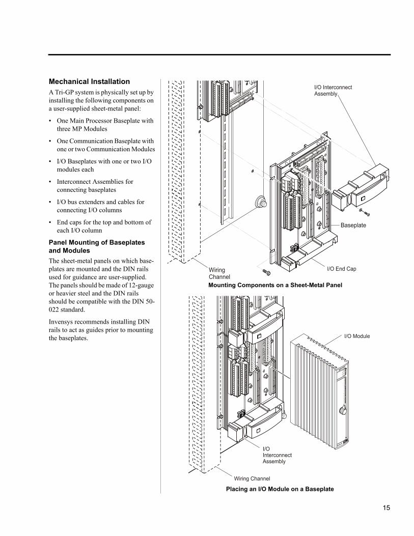
A Tri-GP system is physically set up by installing the following components on a user-supplied sheet-metal panel:
• One Main Processor Baseplate with three MP Modules
• One Communication Baseplate with one or two Communication Modules
• I/O Baseplates with one or two I/O modules each
• Interconnect Assemblies for connecting baseplates
• I/O bus extenders and cables for connecting I/O columns
• End caps for the top and bottom of each I/O column
Panel Mounting of Baseplates and Modules
The sheet-metal panels on which base-plates are mounted and the DIN rails used for guidance are user-supplied. The panels should be made of 12-gauge or heavier steel and the DIN rails should be compatible with the DIN 50-022 standard.
Invensys recommends installing DIN rails to act as guides prior to mounting the baseplates.
Mounting Components on a Sheet-Metal Panel
Placing an I/O Module on a Baseplate
16
Setting up a Tri‐GP System
The basic steps for installing Tri-GP components include:
• Installing DIN rails
• Fastening the baseplates onto the panels
• Joining the baseplates together with interconnect assemblies
• Connecting multiple columns of baseplates with extender modules and I/O bus cables
• Installing the MP, CM, and I/O modules onto the baseplates
Typical Enclosures
When all baseplates, modules, and connective devices are securely mounted on a panel, the entire system is placed in a user-supplied metal enclo-sure with a sealed bottom and a closed door.
Either of the following can be used:
• A floor-mounted enclosure such as a Rittal cabinet for one I/O column
• A wall-mounted enclosure such as a Hoffman box for two or more I/O columns
Connecting Logic Powerand Field Power
The Tri-GP controller offers a flexible power-handling system.
Logic Power
Logic power is distributed down each column. This distribution is redundant and both must be wired. If not wired, a system alarm is generated. If a single power source is used, it must be jump-ered to the redundant termination points.
Field Power
Field power is also redundant and both wiring points must be wired. Each base-plate is isolated from all other base-plates. This configuration provides you with a wide range of possibilities for field power distribution.
Connecting to a PC Running TriStation 1131 SoftwareThe Tri-GP controller communicates with the PC running TriStation 1131 software using Ethernet (TCP/IP) protocol or DLC protocol. The PC running TriStation 1131 software requires the installation of the following:
• A Network Interface (NIC) card
• Ethernet or Data Link Control (DLC) protocol
• A connection between an MP port or CM port
For more information, see the Commu-nication Guide for Tri-GP v2 Systems.
Connecting Field DevicesField devices are wired to the termina-tion strips mounted on either the base-plate or the external termination panel.
17
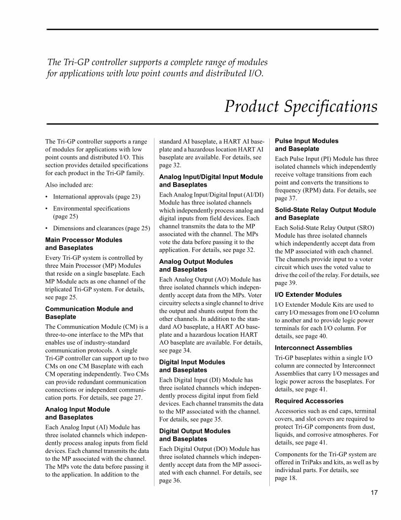
The Tri‐GP controller supports a complete range of modules for applications with low point counts and distributed I/O.
Product Specifications
The Tri-GP controller supports a range of modules for applications with low point counts and distributed I/O. This section provides detailed specifications for each product in the Tri-GP family.
Also included are:
• International approvals (page 23)
• Environmental specifications (page 25)
• Dimensions and clearances (page 25)
Main Processor Modulesand Baseplates
Every Tri-GP system is controlled by three Main Processor (MP) Modules that reside on a single baseplate. Each MP Module acts as one channel of the triplicated Tri-GP system. For details, see page 25.
Communication Module and Baseplate
The Communication Module (CM) is a three-to-one interface to the MPs that enables use of industry-standard communication protocols. A single Tri-GP controller can support up to two CMs on one CM Baseplate with each CM operating independently. Two CMs can provide redundant communication connections or independent communi-cation ports. For details, see page 27.
Analog Input Moduleand Baseplates
Each Analog Input (AI) Module has three isolated channels which indepen-dently process analog inputs from field devices. Each channel transmits the data to the MP associated with the channel. The MPs vote the data before passing it to the application. In addition to the
standard AI baseplate, a HART AI base-plate and a hazardous location HART AI baseplate are available. For details, see page 32.
Analog Input/Digital Input Module and Baseplates
Each Analog Input/Digital Input (AI/DI) Module has three isolated channels which independently process analog and digital inputs from field devices. Each channel transmits the data to the MP associated with the channel. The MPs vote the data before passing it to the application. For details, see page 32.
Analog Output Modulesand Baseplates
Each Analog Output (AO) Module has three isolated channels which indepen-dently accept data from the MPs. Voter circuitry selects a single channel to drive the output and shunts output from the other channels. In addition to the stan-dard AO baseplate, a HART AO base-plate and a hazardous location HART AO baseplate are available. For details, see page 34.
Digital Input Modulesand Baseplates
Each Digital Input (DI) Module has three isolated channels which indepen-dently process digital input from field devices. Each channel transmits the data to the MP associated with the channel. For details, see page 35.
Digital Output Modulesand Baseplates
Each Digital Output (DO) Module has three isolated channels which indepen-dently accept data from the MP associ-ated with each channel. For details, see page 36.
Pulse Input Modulesand Baseplate
Each Pulse Input (PI) Module has three isolated channels which independently receive voltage transitions from each point and converts the transitions to frequency (RPM) data. For details, see page 37.
Solid-State Relay Output Module and Baseplate
Each Solid-State Relay Output (SRO) Module has three isolated channels which independently accept data from the MP associated with each channel. The channels provide input to a voter circuit which uses the voted value to drive the coil of the relay. For details, see page 39.
I/O Extender Modules
I/O Extender Module Kits are used to carry I/O messages from one I/O column to another and to provide logic power terminals for each I/O column. For details, see page 40.
Interconnect Assemblies
Tri-GP baseplates within a single I/O column are connected by Interconnect Assemblies that carry I/O messages and logic power across the baseplates. For details, see page 41.
Required Accessories
Accessories such as end caps, terminal covers, and slot covers are required to protect Tri-GP components from dust, liquids, and corrosive atmospheres. For details, see page 41.
Components for the Tri-GP system are offered in TriPaks and kits, as well as by individual parts. For details, see page 18.

18
Product Specifications
Standard Tri-GP Products
Model Product Name Qty Description Consists of
5101S2 Main Processor TriPak 31
Main Processor ModuleMain Processor Baseplate Kit
3101S22101S2
5201S2 Communication Module TriPak 11
Communication Module Communication Module Baseplate Kit
3201S22201S2
5351S2 Analog Input TriPak 11
Analog Input ModuleAnalog Input Baseplate Kit
3351S22351S2
5361S2 Analog Input/Digital Input TriPak
11
Analog Input/Digital Input ModuleAnalog Input/Digital Input Baseplate Kit
3361S22361S2
5352S2 Analog Input Tripak, RTD/TC/4-20 mA
11
Analog Input ModuleAnalog Input Baseplate, RTD/TC/4-20 mA
3351S22352S2
5354S2 Analog Input TriPak, HART 111
Analog Input ModuleAnalog Input Baseplate Kit, HART,Triconex 4850 HART Multiplexer
3351S22354S21600106-001
5354AS2 Analog Input TriPak, HART, Hazardous Location
111
Analog Input ModuleAnalog Input Baseplate Kit, HART, Hazardous LocationTriconex 4850 HART Multiplexer
3351S22354AS21600106-001
5481-1S2 Analog Output TriPak 11
Analog Output ModuleAO Module Baseplate Kit
3481S22481S2
5482-1S2 Analog Output Tripak, High-Current
11
High-Current Analog Output ModuleAO Module Baseplate Kit
3482S22481S2
5301S2 Digital Input TriPak 11
Digital Input ModuleDigital Input Baseplate Kit
3301S22301S2
5311S2 Digital Input TriPak, High Resolution
11
Digital Input Module, High ResolutionDigital Input Baseplate Kit
3311S22301S2
5312S2 Digital Input TriPak, High Resolution, High Voltage
11
Digital Input Module, High ResolutionDigital Input Baseplate Kit, High Voltage
3311S22302S2
5302S2 Digital Input TriPak, High Voltage
11
Digital Input ModuleDigital Input Baseplate Kit, High Voltage
3301S22302S2
5401S2 Digital Output TriPak 11
Digital Output ModuleDigital Output Baseplate Kit
3401S22401S2
5401LS2 Digital Output TriPak, Low Current
11
Digital Output ModuleDigital Output Baseplate Kit, Low Current
3401S22401LS2
5411HS2 Digital Output TriPak, Supervised, High Current
11
Digital Output Module, SupervisedDigital Output Baseplate Kit, High Current
3411S22401HS2
5402S2 Digital Output TriPak, High Voltage
11
Digital Output ModuleDigital Output Baseplate Kit, High Voltage
3401S22402S2
5451S2 Solid-State Relay Output TriPak 11
Solid-State Relay Output ModuleSolid-State Relay Output Baseplate Kit
3451S22451S2
5382-1S2 Pulse Input TriPak, Enhanced 11
Pulse Input Module, EnhancedPulse Input Baseplate Kit
3382S22381S2
5382AS2 Pulse Input TriPak, Enhanced, Hazardous Location
11
Pulse Input Module, EnhancedPulse Input Baseplate Kit, Hazardous Location
3382S22381AS2
5483S2 Analog Output TriPak, HART 111
Analog Output ModuleAnalog Output Baseplate Kit, HARTTriconex 4850 HART Multiplexer
3481S22483S21600106-001

19
5483AS2 Analog Output TriPak, HART, Hazardous Location
111
Analog Output ModuleAnalog Output Baseplate Kit, HART, Hazard. LocationTriconex 4850 HART Multiplexer
3481S22483AS21600106-001
2101S2 Main Processor Baseplate Kit 11111111
MP BaseplateMP Interconnect AssemblyTri-GP User Documentation (hardcopy)Accessories KitTop End Cap – I/OTop End Cap – MPBottom End Cap – I/OBottom End Cap – MP
3000671-11029208910-4S284012910291229112913
2281 I/O Bus Extender Module Kit 23111
I/O Extender Module2-ft. I/O Bus CablesI/O Interconnect AssemblyTop End Cap – I/OBottom End Cap – I/O
3000678-1004000212-002292129102911
2291 I/O Bus Termination Kit, I/O Baseplate
111
I/O Extender ModuleI/O Interconnect AssemblyI/O Bus Terminator Kit (Set of 3)
3000678-10029213900064-003
2292 I/O Bus Termination Kit, MP Baseplate
111
I/O Extender ModuleMP Interconnect AssemblyI/O Bus Terminator Kit (Set of 3)
3000678-10029203900064-003
2301S2 Digital Input Baseplate Kit 1111
I/O BaseplateI/O Interconnect AssemblySlot CoverTerminal Cover
3000673-030292129002901
2302S2 Digital Input Baseplate Kit, High Voltage
12112
I/O External Termination BaseplateExternal Termination Panel (Solid State Relay Input)I/O Interconnect AssemblySlot CoverInterface Cable, 10 ft
3000721-3103000762-110292129009105-310F
SSR Input Modules for use with SSR Input ETP100 to 240 VAC (ordered separately) 1300447-001
2302AS2 Digital Input Baseplate Kit, Hazardous Location
11111
I/O External Termination BaseplateExternal Termination Panel KitI/O Interconnect AssemblySlot CoverTerminal Cover
3000989-3159573-610F292129002901
2342S2 Analog Input/Digital Input Baseplate Kit, External Termination
111
I/O External Termination BaseplateI/O Interconnect AssemblySlot Cover
3000721-14029212900
2342AS2 Analog Input/Digital Input Baseplate Kit, Hazardous Location
1111
I/O External Termination BaseplateI/O Interconnect AssemblySlot CoverAI/DI ETP Kit, Hazardous Location
3000989-145292129009793-610F
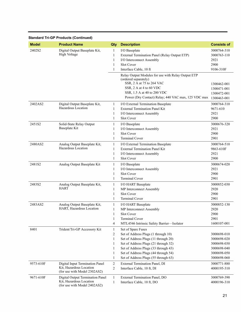
Standard Tri-GP Products (Continued)
Model Product Name Qty Description Consists of

20
Product Specifications
2351S2 Analog Input Baseplate Kit 1111
I/O BaseplateI/O Interconnect AssemblySlot CoverTerminal Cover
3000675-030292129002901
2352S2 Analog Input Baseplate Kit for TC, RTD, and 4-20mA (requires 2 of part number 9764-510F)
111
I/O External Termination BaseplateI/O Interconnect AssemblySlot Cover
3000721-11029212900
2352AS2 Analog Input Baseplate Kit, Hazardous Location
1111
I/O External Termination BaseplateExternal Termination Panel KitI/O Interconnect AssemblySlot Cover
3000989-1159792-310F29212900
2354S2 Analog Input Baseplate Kit, HART
1111
I/O HART BaseplateMP Interconnect AssemblySlot CoverTerminal Cover
3000851-020292029002901
2354AS2 Analog Input Baseplate Kit, HART, Hazardous Location
1111
I/O HART BaseplateMP Interconnect AssemblySlot CoverTerminal Cover
3000851-120292029002901
2361S2 Analog Input/Digital Input Baseplate Kit
1111
I/O BaseplateI/O Interconnect AssemblySlot CoverTerminal Cover
3000675-040292129002901
2381S2 Pulse Input Baseplate Kit 1111
I/O BaseplateI/O Interconnect AssemblySlot CoverTerminal Cover
3000719-110292129002901
2381AS2 Pulse Input Baseplate Kit, Hazardous Location
1111
I/O Hazardous Location BaseplateI/O Interconnect AssemblySlot CoverTerminal Cover
3000719-210292129002901
2401S2 Digital Output Baseplate Kit 1111
I/O BaseplateI/O Interconnect AssemblySlot CoverTerminal Cover
3000674-040292129002901
2401HS2 Digital Output Baseplate Kit, High Current
1111
I/O BaseplateI/O Interconnect AssemblySlot CoverTerminal Cover
3000975-040292129002901
2401LS2 Digital Output Baseplate Kit, Low Current
1111
I/O BaseplateI/O Interconnect AssemblySlot CoverTerminal Cover
3000715-040292129002901
Standard Tri-GP Products (Continued)
Model Product Name Qty Description Consists of
21
2402S2 Digital Output Baseplate Kit, High Voltage
11111
I/O BaseplateExternal Termination Panel (Relay Output ETP)I/O Interconnect AssemblySlot CoverInterface Cable, 10 ft
3000764-3103000763-110292129009106-310F
Relay Output Modules for use with Relay Output ETP (ordered separately)
SSR, 2 A at 75 to 264 VACSSR, 2 A at 4 to 60 VDCSSR, 1.5 A at 40 to 200 VDCPower (Dry Contact) Relay; 440 VAC max, 125 VDC max
1300462-0011300471-0011300472-0011300463-001
2402AS2 Digital Output Baseplate Kit, Hazardous Location
1111
I/O External Termination BaseplateExternal Termination Panel KitI/O Interconnect AssemblySlot Cover
3000764-3109671-61029212900
2451S2 Solid-State Relay Output Baseplate Kit
1111
I/O BaseplateI/O Interconnect AssemblySlot Cover Terminal Cover
3000676-320292129002901
2480AS2 Analog Output Baseplate Kit, Hazardous Location
1111
I/O External Termination BaseplateExternal Termination Panel KitI/O Interconnect AssemblySlot Cover
3000764-5109863-610F29212900
2481S2 Analog Output Baseplate Kit 1111
I/O BaseplateI/O Interconnect AssemblySlot CoverTerminal Cover
3000674-020292129002901
2483S2 Analog Output Baseplate Kit, HART
1111
I/O HART BaseplateMP Interconnect AssemblySlot CoverTerminal Cover
3000852-030292029002901
2483AS2 Analog Output Baseplate Kit, HART, Hazardous Location
11114
I/O HART BaseplateMP Interconnect AssemblySlot CoverTerminal CoverMTL4546 Intrinsic Safety Barrier—Isolator
3000852-1302920290029011600107-001
8401 Trident/Tri-GP Accessory Kit 1211111
Set of Spare FusesSet of Address Plugs (1 through 10)Set of Address Plugs (11 through 20)Set of Address Plugs (21 through 32)Set of Address Plugs (33 through 43)Set of Address Plugs (44 through 54)Set of Address Plugs (55 through 63)
3000698-0103000698-0203000698-0303000698-0403000698-0503000698-060
9573-610F Digital Input Termination Panel Kit, Hazardous Location(for use with Model 2302AS2)
22
External Termination Panel, DIInterface Cable, 10 ft, DI
3000771-8804000195-310
9671-610F Digital Output Termination Panel Kit, Hazardous Location(for use with Model 2402AS2)
11
External Termination Panel, DOInterface Cable, 10 ft, DO
3000769-3904000196-310
Standard Tri-GP Products (Continued)
Model Product Name Qty Description Consists of

22
Product Specifications
9764-510F RTD/TC/AI Termination Panel Kit (for use with Model 2352S2)
11
External Termination Panel, RTD/TC/AIInterface Cable, 10 ft
3000712-1004000189-510
Signal Conditioning Modules for use with 9764-510F (ordered separately)
4–20 mA32F to 392F (0C to 200C), RTD32F to 1112F (0C to 600C), RTD32F to 1400F (0C to 760C), Type J TC32F to 2372F (0C to 1300C), Type K TC32F to 752F (0C to 400C), Type T TC32F to 1652F (0C to 900C), Type E TCShorting Plug
1600048-2201600048-0301600048-0401600048-1101600048-1201600048-1301600048-1401600048-300
9792-310F Analog Input Termination Panel Kit, Hazardous Location(for use with Model 2352AS2)
11
External Termination Panel, AIInterface Cable, 10 ft, AI
3000771-7104000197-510
9793-610F Analog Input/Digital Input Termination Panels Kit, Hazardous Location(for use with Model 2342AS2)
1111
External Termination Panel, AIExternal Termination Panel, DIInterface Cable, 10 ft, AIInterface Cable, 10 ft, DI
3000771-7103000771-8804000197-5104000195-310
9863-610F Analog Output Termination Panel Kit, Hazardous Location(for use with Model 2480AS2)
11
External Termination Panel, AOInterface Cable, 10 ft, AO
3000770-9604000198-510
Triconex 4850 Triconex 4850 HART Multiplexer
1 Triconex 4850 HART Multiplexer 1600106-001
7254-13S2 TriStation 1131 Developer’s Workbench v4.8.0 for Tri-GP
1
1
CD containing:Developer’s Workbench (software)TriStation 1131 Help Documentation (online)
TriStation 1131 v4.8.0 Documentation Set
3000755-829
3000760-930
7255-13S2 TriStation 1131 Developer’s Workbench v4.8.0 with CEMPLE for Tri-GP
1
1
CD containing:Developer’s Workbench (software)TriStation 1131 Help Documentation (online)
TriStation 1131 v4.8.0 Documentation Set
3000755-828
3000760-930
8910-4S2 Triconex General Purpose User Documentation (hardcopy)
11
Planning and Installation Guide for Tri-GP v2 SystemsCommunication Guide for Tri-GP v2 Systems
9700122-0019700123-001
8747-11 TriStation 1131 v4.8.0 User Documentation (hardcopy)
111111
TriStation 1131 Developer’s GuideTriStation 1131 Libraries ReferenceSafety Considerations Guide for Trident v2Safety Considerations Guide for Tri-GP v2Safety Considerations Guide for Trident v1Safety Considerations Guide for Tricon
9700100-0119700098-0109700112-0039700124-0019700096-0029700097-007
7523-4 Triconex DDE Server v4.3.0 11
CD containing DDE Server software and doc.DDE Server, v4.3.0 Documentation Set (hardcopy)
3000723-3039700108-004
7521-6 SOE Recorder v4.3.0 11
CD containing SOE Recorder software and doc.SOE Recorder, v4.3.0 Documentation Set (hardcopy)
3000708-4309700081-008
7260-7 Enhanced Diagnostic Monitor v2.5.0
11
CD containing Enhanced Diagnostic Monitor softwareEnhanced Diagnostic Monitor, v2.5.0 Documentation Set (hardcopy)
3000796-0099700107-008
Contact Invensys for current model number
Triconex Documentation Set 1 CD containing documentation in PDF format
Standard Tri-GP Products (Continued)
Model Product Name Qty Description Consists of

23
International Approvals
The Tri-GP controller has been certi-fied as complying with multiple inter-nationally recognized standards by the following internationally recognized certification agencies, these certifica-tions have qualified the Tri-GP controller for use around the world in safety critical applications. Test reports from the various certification agencies are available upon request.
Canadian Standards Association
CSA has certified that the Tri-GP v2.x controller is in full compliance with the following internationally recognized electrical safety standards and is quali-fied for general use in North American and other jurisdictions requiring compliance with these standards.
European Union CE Mark
Based upon the independent TÜV eval-uation and test results, Invensys has certified the Tri-GP v2.x controller
suitable to use in the European Union and all other jurisdictions requiring compliance with the European Union EMC Directive No. 89/336/EEC and Low Voltage Equipment Directive No. 72/23/EEC. See Certificate of Compli-ance for details.
To ensure maximum reliability and trouble-free operation, the Tri-GP and associated wiring must be installed following the guidelines outlined in the Planning and Installation Guide.
Certifying Agency Standard Number Title
Canadian Standards Association
CAN/CSA-C22.2 No.0-M91 General Requirements—Canadian Electrical Code, Part II
CSA Std C22.2 No.0.4-M1982 Bonding and Grounding of Electrical Equipment (Protective Grounding)
CAN/CSA C22.2 No 1010.1-92 Safety Requirements for Electrical Equipment for Measurement, Control, and Laboratory Use, Part 1: General Requirements
UL 3121-1 1998-07-14 Process Control Equipment
European Union CE Mark
IEC 61131-2 Programmable Controllers Part 2: Equipment Requirements and Test. Overvoltage Category II is assumed.
Factory Mutual 3611 Electrical Equipment for use in Class I-Division 2; Class II-Division 2; and Class III-Divisions 1 and 2, Hazardous Locations
3810 Electrical and Electronic Test, Measuring and Process Control Equipment
3600 Electrical Equipment for Use in Hazardous (Classified) Locations-General Requirements
TÜV Rheinland IEC 61508, Parts 1-7, 2000 Functional safety of electrical/electronic/programmable electronic safety-related systems
IEC 61511:2004 Functional safety - Safety instrumented systems for the process industry sector
IEC 61131-2:2007 Programmable Controllers Part 2: Equipment Requirements and Test. Overvoltage Category II is assumed.
IEC 61326-3-1:2008 Electrical equipment for measurement, control and laboratory use - EMC requirements - Part 3-1: Immunity requirements for safety-related systems and for equipment intended to perform safety-related functions (functional safety) - General industrial applications
ANSI/ISA-84.00.01-2004(IEC 61511-1 Mod)
Functional Safety: Safety Instrumented Systems for the Process Industry Sector - Part 1: Framework, Definitions, System, Hardware and Software Requirements
EN50156-1:2004 Electrical equipment for furnaces and ancillary equipment. Requirements for application design and installation
EN 50178:1998 Electronic equipment for use in power installations
NFPA 72:2007 National Fire Alarm Code
NFPA 85:2007 Boiler and Combustion Systems Hazards Code, 2007 Edition
EN 54-2:1997/A1:2006a Fire detection and fire alarm systems. Control and indicating equipment.
a.To comply with the requirements of EN 54-2:1997/A1:2006, the Tri-GP system must be installed in a metal enclosure with a sealed bottom and a closed door, connected to Safety Ground, and it must be installed in an area with an access level greater than 2.

24
Product Specifications
To comply with the CE Mark require-ment for emissions and conducted susceptibility, and EU directives, these guidelines must be followed:
• The entire Tri-GP system must be installed in a metal enclosure with a sealed bottom and a closed door, connected to Safety Ground.
• Field power supplies must be approved for use in safety extra-low-voltage (SELV) circuits according to the requirements of IEC 61010-1.
To comply with the requirements of EN 54-2:1998, the system must be located in an area with an access level greater than 2.
To comply with standards related to conducted disturbance, a Schaffner® FN 2410 line filter, or equivalent, must be installed between power supplies and baseplates.
TÜV Rheinland
TÜV has certified that the Tri-GP v2.x is in full compliance with the interna-tionally recognized standards listed on page 23.
Factory Mutual
FM has certified the Tri-GP v2.x controller is in full compliance with the international recognized standards listed on page 23 and is qualified for use in Class I, Division 2 Temperature T4, Groups A, B, C, and D hazardous indoor locations. In North America, the field signals used with ATEX-compliant external termination panels are certified for use in Class 1, Division 2, Groups C and D. For hazardous loca-tion applications, redundant power sources must be used for system power. Also, any signal going to or through a hazardous atmosphere must use hazardous location protection, such as an IS Barrier.
Feature Specification
Operating temperature -4° F to +158° F (-20° C to +70° C) ambient (which is the air temperature measured at the bottom of the baseplate), per IEC 60068-2-14, tests Na and Nb
Storage temperature -40° F to +185° F (-40° C to +85° C) per IEC 60068-2-2, test Bb, IEC 60068-2-1, test Ab, and IEC 60068-2-30, test Db
Relative humidity 5% to 95%, non-condensing
Corrosive environment Class G3 Level as defined in ISA Standard S71.04, based on exposure testing according to EIA Standard 364-65A, Class III
Sinusoidal vibrations per axis 1.75 mm displacement @ 5 to 8.4 Hz (continuous)0.5 g acceleration @ 8.4 to 150 Hz (continuous)3.5 mm displacement @ 5 to 8.4 Hz (occasional)1.0 g acceleration @ 8.4 to 150 Hz (occasional)All tests per IEC 60068-2-6, test Fc
Shock 15 g, 11 ms, half-sine, 3 axis, per IEC 60068-2-27, test Ea
Electrostatic discharge IEC 61000-4-2, 4 kV contact, 8kV air
Conducted susceptibility IEC 61000-4-4, Fast Transient/Burst, 2 kV power & unshielded AC I/O, 1 kV signal and communication linesIEC 61000-4-5, Surge Withstand, 2 kV CM2/1 kV DM2
AC power and I/O, 1 kV CM2 I/O, shielded and communication, 0.5 kV CM2/0.5 kV DM2 DC powerIEC 61000-4-6, RFI, 0.15-80 MHz, 10 V IEC 61000-4-18, Damped Oscillatory Wave, 0.5 kV CM shielded, 2.5 kV CM/1 kV DM unshielded AC I/O & power, 1 kV CM/0.5 kV DM I/O
Radiated susceptibility IEC 61000-4-3, Radio Frequency Electromagnetic Fields, 80–1000 MHz: 10 V/m, 1.4–2.0 GHz: 3 V/m, 2.0–2.7 GHz: 1 V/m
Conducted emissions CISPR 16, Class A, 0.15-30MHz, 73-79db when installed per the guidelines of the P & I Guide.
Radiated emissionsa
a. For European Union CE Mark and conducted susceptibility compliance, the Tri-GP system must be mounted in a metal enclosure with a sealed bottom and a closed door, connected to Safety Ground. Addi-tionally, the system must be located in an area with an access level greater than 2 to comply with the requirements of EN 54-2:1998.
CISPR 11, Class A, 30-1000 MHz @ 10m, 4-47 db when installed per the guidelines of P & I Guide.
Power interruptions IEC 61000-4-29, 1 ms battery, 10 ms DC power supply
Cable flame test ratingb
b.Applies to cables shipped after April 1, 2009.
Interface cables(connect external termination panels to baseplates):FT4 Vertical Flame Test-Cables in Cable Trays per C.S.A. C22.2 No. 0.3-92 Para 4.11.4c
I/O bus cables(connect columns of baseplates):FT6 Horizontal Flame & Smoke Test-per C.S.A. C22.2 No. 0.3-92 Appendix Bd
c.Cables will be marked with FT4 or CMG rating, but they all actually meet the more stringent FT4 rating.
d.Cables will be marked with FT6 or CMP rating, but they all actually meet the more stringent FT6 rating.
25
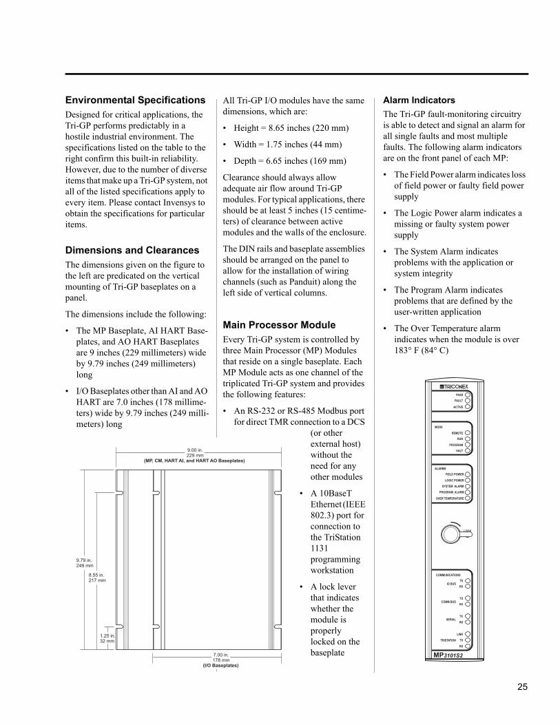
Environmental Specifications
Designed for critical applications, the Tri-GP performs predictably in a hostile industrial environment. The specifications listed on the table to the right confirm this built-in reliability. However, due to the number of diverse items that make up a Tri-GP system, not all of the listed specifications apply to every item. Please contact Invensys to obtain the specifications for particular items.
Dimensions and Clearances
The dimensions given on the figure to the left are predicated on the vertical mounting of Tri-GP baseplates on a panel.
The dimensions include the following:
• The MP Baseplate, AI HART Base-plates, and AO HART Baseplates are 9 inches (229 millimeters) wide by 9.79 inches (249 millimeters) long
• I/O Baseplates other than AI and AO HART are 7.0 inches (178 millime-ters) wide by 9.79 inches (249 milli-meters) long
All Tri-GP I/O modules have the same dimensions, which are:
• Height = 8.65 inches (220 mm)
• Width = 1.75 inches (44 mm)
• Depth = 6.65 inches (169 mm)
Clearance should always allow adequate air flow around Tri-GP modules. For typical applications, there should be at least 5 inches (15 centime-ters) of clearance between active modules and the walls of the enclosure.
The DIN rails and baseplate assemblies should be arranged on the panel to allow for the installation of wiring channels (such as Panduit) along the left side of vertical columns.
Main Processor Module
Every Tri-GP system is controlled by three Main Processor (MP) Modules that reside on a single baseplate. Each MP Module acts as one channel of the triplicated Tri-GP system and provides the following features:
• An RS-232 or RS-485 Modbus port for direct TMR connection to a DCS
(or other external host) without the need for any other modules
• A 10BaseT Ethernet (IEEE 802.3) port for connection to the TriStation 1131 programming workstation
• A lock lever that indicates whether the module is properly locked on the baseplate
Alarm Indicators
The Tri-GP fault-monitoring circuitry is able to detect and signal an alarm for all single faults and most multiple faults. The following alarm indicators are on the front panel of each MP:
• The Field Power alarm indicates loss of field power or faulty field power supply
• The Logic Power alarm indicates a missing or faulty system power supply
• The System Alarm indicates problems with the application or system integrity
• The Program Alarm indicates problems that are defined by the user-written application
• The Over Temperature alarm indicates when the module is over 183° F (84° C)
LOCK
REMOTERUN
PROGRAM
HALT
TX
RX
TX
RX
TX
RX
LINK
TX
RX
PASS
FAULT
ACTIVE
3101S2MP
MODE
COMMUNICATIONS
IO BUS
COMM BUS
SERIAL
TRISTATION
FIELD POWER
SYSTEM ALARM
PROGRAM ALARM
OVER TEMPERATURE
LOGIC POWER
ALARMS
1.25 in.32 mm
8.55 in.217 mm
9.79 in.249 mm
9.00 in.229 mm
(MP, CM, HART AI, and HART AO Baseplates)
7.00 in.178 mm
(I/O Baseplates)

26
Product Specifications
System Status Indicators
The system status indicators identify the processing state of the module. The status indicators include the following:
• The Pass indicator identifies when the module is operating normally.
• The Active indicator blinks once per scan when executing an application.
• The Fault indicator identifies when the processor has an internal fault.
Other Indicators
Other indicators on the MP include the following:
• Mode indicators (Remote, Run, Program, and Halt) identify the operating state of the entire Tri-GP system.
• Communication indicators that identify the type of communication occurring
Physical Description
Each MP provides 16 megabytes of DRAM for the user-written application, sequence-of-events (SOE) and I/O data, diagnostics, and communication buffers.
The three MPs compare their respective data during every scan using the TriBus, a high-speed, fault-tolerant inter-processor bus. The MPs commu-nicate with the I/O modules over a TMR HDLC I/O bus that operates at 2 megabits per second.
In addition to the TriStation 1131 and Modbus ports and alarm connectors, the MP Baseplate provides redundant, 24-volt fused logic power connectors. Logic power supplied here can operate the MPs and carry to the I/O Baseplates as well, so that no other logic power supplies are needed for the column.
Modbus Portsfor Direct DCSConnections
TriStationConnectors
Logic PowerFuses
Logic Powerand AlarmTerminal Blocks
Fuses and BlownFuse Indicators
DebugConnectors
NodeAddress
+ñ
DSP1
DSP2
DSP3
DSP4
FUSE
FUSE
1
MP Baseplate ConnectorsMP Baseplate

27
Communication Module
The Communication Module (CM) is a one-to-one interface to the MPs. The Tri-GP v2 CM enables communication with:
• External host computers
• Distributed control systems (DCS)
• Open networks
Two CMs can provide redundant communication connections or addi-tional independent communications ports.
LOCK
TX
RX
LINK
LINK
TX
RX
PASS
FAULT
ACTIVE
3201S2CM
COMMUNICATIONS
TX
RXSERIAL
TX
RXSERIAL
TX
RXSERIAL
NET 1
NET 2
• Network printers
• Other Tri-GP v2 systems
• Tricon™ version 9–10 systems
A single Tri-GP controller can support up to two CMs on one CM Baseplate. Each CM operates independently and supports three RS-232 or RS-485 serial ports and two Ethernet ports per CM.
CM Front PanelCM Baseplate

28
Product Specifications
Communication Capabilities
Each CM provides the following communication capabilities:
• Serial ports
• Network ports
• Multiple protocol support
Serial Ports
Each CM provides three optically isolated RS-232 or RS-485 serial ports which are user-configurable for Modbus point-to-point or multi-point (network) connections. Transmission rates up to 115 kilobits per second per port can be selected.
Network Ports
Each CM provides two network ports which are configured as follows:
One 10-megabit Ethernet port, with the following connectors:
• 10BaseT
• Attachment unit interface (AUI) for a 10-megabit media adapter unit (MAU)
One 100-megabit Ethernet port, with the following connectors:
• 100BaseTX
• Media independent interface (MII) for a 100-megabit MAU
Media adapter units may be used in place of the 10/100 BaseT RJ-45 twisted-pair connections to convert the CM network ports to other Ethernet media types or to extend network distances.
Supported Protocols
Each CM serial port supports these protocols:
• Modbus master (RTU)
• Modbus slave (ASCII or RTU)
• JetDirect Network Printer Server DLC/LLC
NOTE
The Tri-GP CM supports a maximum of four Modbus TCP ports.
Each CM Net1 network port supports Triconex Time Synchronization via DLC.
Each CM network port supports these protocols:
• TSAA (UDP/IP)
• TSAA with IP Multicast (UDP/IP)
• TriStation 1131
• Peer-to-Peer (UDP/IP)
• Peer-to-Peer (DLC)
• Modbus Master or Slave (TCP)
• Triconex Time Synchronization via UDP/IP
• SNTP Triconex Time Synchronization
CM Baseplate Connectors
29
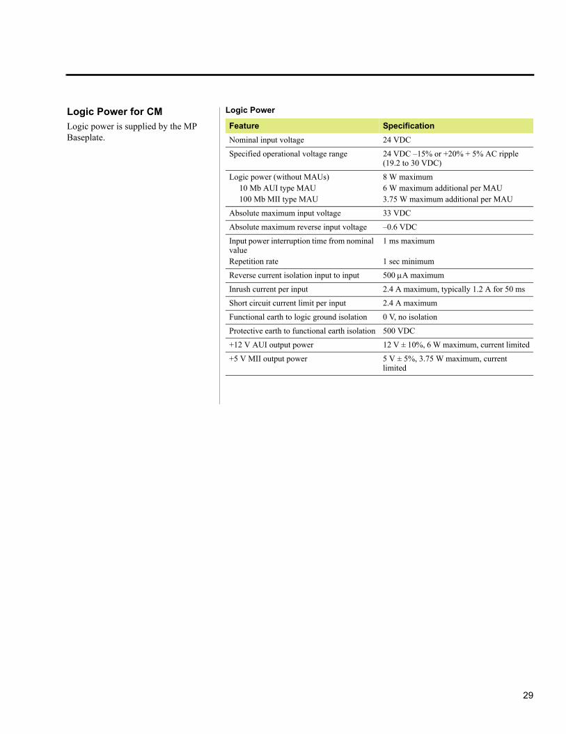
Logic Power for CM
Logic power is supplied by the MP Baseplate.
Logic Power
Feature Specification
Nominal input voltage 24 VDC
Specified operational voltage range 24 VDC –15% or +20% + 5% AC ripple (19.2 to 30 VDC)
Logic power (without MAUs)10 Mb AUI type MAU 100 Mb MII type MAU
8 W maximum6 W maximum additional per MAU3.75 W maximum additional per MAU
Absolute maximum input voltage 33 VDC
Absolute maximum reverse input voltage –0.6 VDC
Input power interruption time from nominal valueRepetition rate
1 ms maximum
1 sec minimum
Reverse current isolation input to input 500 A maximum
Inrush current per input 2.4 A maximum, typically 1.2 A for 50 ms
Short circuit current limit per input 2.4 A maximum
Functional earth to logic ground isolation 0 V, no isolation
Protective earth to functional earth isolation 500 VDC
+12 V AUI output power 12 V ± 10%, 6 W maximum, current limited
+5 V MII output power 5 V ± 5%, 3.75 W maximum, current limited

30
Product Specifications
Common Features for I/O Modules and BaseplatesThe Digital Input (DI) Module and Baseplate shown below serve as exam-ples for all of the Tri-GP I/O modules and baseplates whose appearance is similar. The following pages provide detailed specifications for all of the I/O modules and baseplates.
Each I/O module occupies one of two slots on the baseplate that constitute an I/O set. The left module occupies the slot below the “L” label on the base-
plate and the right module occupies the slot below the “R” label. At any time, the status of either the left or right module can be active or hot-spare depending on which module is in control.
All types of I/O modules support a hot-spare module. Each module is mechan-ically keyed to prevent improper instal-lation in a configured baseplate.
Each I/O Baseplate includes one I/O Interconnect Assembly, one Slot Cover, and one Terminal Cover.
For most types of I/O baseplates, the wiring for field devices is connected directly to terminals on the baseplate, which are compression terminals that are compatible with 24 to 12
(0.2 mm2 to 3.3 mm2) AWG wiring.
The maximum operating temperature for all types of I/O modules is 158° F (70° C) ambient.
LOCK
1
17
2
18
3
19
4
20
5
21
6
22
7
23
8
24
9
25
11
27
12
28
13
29
14
30
15
31
16
32
10
26
PASS
FAULT
ACTIVE
FIELD PWR
3301S2DI 24v
DI Baseplate DI Front Panel

31
Common Specifications for All I/O Modules
The following tables identify the logic and field power specifications for all I/O modules.
Logic Power
Feature Specification
Nominal input voltage 24 VDC
Voltage range 24 VDC –15% or +20% +5% AC ripple (+19.2 to +30 VDC)
Logic power <3 W
Absolute maximum input voltage 33 VDC
Absolute maximum reverse input voltage – 0.6 VDC
Input power interruption time from nominal 1 ms maximum
Power interruption interval 1 sec minimum
Reverse current isolation input to input 500 A maximum
Inrush current per input 2.4 A maximum
Short circuit current limit per input 2.4 A maximum
Functional earth to logic ground isolation 0 V, no isolation
Protective earth to functional earth isolation 500 VDC, minimum
Field Power
Feature Specification
Nominal field voltage 24 VDC
Specified operational voltage range 24 VDC –15% or +20% +5% AC ripple (+19.2 to +30 VDC)a
a.For the PI Module, the voltage range is configurable in TriStation 1131 software.
Power See module specifications
Absolute maximum input voltage 33 VDC
Absolute maximum reverse input voltage – 0.6 VDC
Input power interruption time from nominal Not applicable
Power interruption interval Not applicable
Reverse current isolation 500 A maximum
Functional earth to protective earth isolation 500 VDC, minimum
Functional earth to functional earth (logic ground) isolation
800 VDC, minimum

32
Product Specifications
Asset Management Software running on a PC.
• Model 2354AS2, which is used in 4-20 mA applications in hazardous locations and enables communication between HART field devices and Configuration and Asset Management Software running on a PC.
and may continue to operate properly with multiple faults.
AI Modules support a hot-spare module. Each AI Module is mechani-cally keyed to prevent improper instal-lation in a configured baseplate.
The Model 3351S2 AI Module can be used with these baseplates:
• Model 23512351S2, which is used in typical 4-20 mA applications.
• AI External Termination Baseplate, which is used with the Model 9764-510F RTD/TC/AI External Termination Panel or the Model 9792-310F AI Hazardous Location External Termination Panel.
• Model 2354S2, which is used in 4-20 mA applications and enables communication between HART field devices and Configuration and
Analog Input Module
Each TMR Analog Input Module has three isolated sets of electronics, called channels, which independently process field data input to the module. Each channel places the processed data in an array and transmits this array, on request, to the MP associated with that channel. The MPs vote the data before passing it to the application. In TMR mode, the data passed is mid-value. In dual mode, the data passed is the average.
AI Modules include complete, ongoing diagnostics for each channel. If the diagnostics detect a failure on any channel, the Fault indicator turns on and activates the system alarm. The Fault indicator identifies a channel fault, not a complete module failure. AI Modules are guaranteed to operate properly in the presence of a single fault
Model 3351S2 Analog Input Module Specifications
Feature Specification
Points 32, commoned
Nominal input current 4–20 mA DC
Specified operational current range 2–22 mA DC
Absolute maximum field voltage 33 VDC
Absolute maximum reverse field voltage – 0.6 VDC
Absolute maximum input current 50 mA DC
Input bandwidth (3dB) 16 Hz
Source impedance 180
Input impedance (with baseplate) 250
I to V resistor 100 0.01%
Resolution 12 bits
Absolute error 0.15% of full scale (20 mA)
Diagnostic Force-to-value diagnostic (FVD)
Scan time < 1 ms for all 32 points
Functional earth to protective earth isolation
500 VDC, minimum
Functional earth to functional earth (logic) isolation
800 VDC, minimum
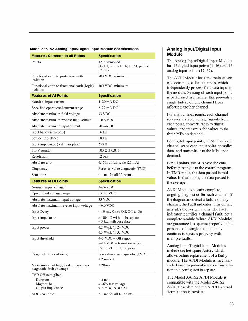
33
Model 3361S2 Analog Input/Digital Input Module Specifications
Features Common to all Points Specification
Points 32, commoned(16 DI, points 1–16; 16 AI, points 17–32)
Functional earth to protective earth isolation
500 VDC, minimum
Functional earth to functional earth (logic) isolation
800 VDC, minimum
Features of AI Points Specification
Nominal input current 4–20 mA DC
Specified operational current range 2–22 mA DC
Absolute maximum field voltage 33 VDC
Absolute maximum reverse field voltage – 0.6 VDC
Absolute maximum input current 50 mA DC
Input bandwidth (3dB) 16 Hz
Source impedance 180
Input impedance (with baseplate) 250
I to V resistor 100 0.01%
Resolution 12 bits
Absolute error 0.15% of full scale (20 mA)
Diagnostic Force-to-value diagnostic (FVD)
Scan time < 1 ms for all 32 points
Features of DI Points Specification
Nominal input voltage 0–24 VDC
Operational voltage range 15–30 VDC
Absolute maximum input voltage 33 VDC
Absolute maximum reverse input voltage – 0.6 VDC
Input Delay < 10 ms, On to Off, Off to On
Input impedance > 100 kwithout baseplate~ 3 kwith baseplate
Input power 0.2 W/pt, @ 24 VDC0.5 W/pt, @ 33 VDC
Input threshold 0–5 VDC = Off region6–14 VDC = transition region15–30 VDC = On region
Diagnostic (loss of view) Force-to-value diagnostic (FVD), < 2 ms/test
Maximum input toggle rate to maintain diagnostic fault coverage
< 20/sec
FVD Off state glitchDurationMagnitudeOutput impedance
< 2 ms 36% test voltage0–5 VDC, 100 k
ADC scan time < 1 ms for all DI points
Analog Input/Digital Input Module
The Analog Input/Digital Input Module has 16 digital input points (1–16) and 16 analog input points (17–32).
The AI/DI Module has three isolated sets of electronics, called channels, which independently process field data input to the module. Sensing of each input point is performed in a manner that prevents a single failure on one channel from affecting another channel.
For analog input points, each channel receives variable voltage signals from each point, converts them to digital values, and transmits the values to the three MPs on demand.
For digital input points, an ASIC on each channel scans each input point, compiles data, and transmits it to the MPs upon demand.
For all points, the MPs vote the data before passing it to the control program. In TMR mode, the data passed is mid-value. In dual mode, the data passed is the average.
AI/DI Modules sustain complete, ongoing diagnostics for each channel. If the diagnostics detect a failure on any channel, the Fault indicator turns on and activates the system alarm. The Fault indicator identifies a channel fault, not a complete module failure. AI/DI Modules are guaranteed to operate properly in the presence of a single fault and may continue to operate properly with multiple faults.
Analog Input/Digital Input Modules include the hot-spare feature which allows online replacement of a faulty module. The AI/DI Module is mechani-cally keyed to prevent improper installa-tion in a configured baseplate.
The Model 3361S2 AI/DI Module is compatible with the Model 2361S2 AI/DI Baseplate and the AI/DI External Termination Baseplate.

34
Product Specifications
Analog Output Modules
Each TMR Analog Output Module has three isolated sets of electronics, called channels, which independently accept data from the MP associated with each channel. The channels provide input to voter circuitry to select a single channel to drive the output. Special circuitry is used to ensure that the channels that are not driving the output are shunted so they cannot affect the output.
AO Modules include complete, ongoing diagnostics for each channel. If the diagnostics detect a failure on any channel, the Fault indicator turns on and activates the system alarm. The Fault indicator identifies a channel fault, not a complete module failure. AO Modules are guaranteed to operate properly in the presence of a single fault and may continue to operate properly with multiple faults.
Analog Output Module Specifications
Model Number 3481S2 3482S2
Points 4, commoned-return, DC-coupled 4, commoned-return, DC-coupled
Isolated points None None
Output current range 4–20 mA output, controlled0–22 mA over-range0 mA output capability (step function < 2 mA)
4–40 mA output, controlled0–44 mA over-range0 mA output capability (step function <4 mA)
Output accuracy <0.25% (in range of 4–20 mA) of FSR (0–22 mA), from 32° F to 158° F (0° C to 70° C)
< 0.25% (in range of 4–40 mA) of FSR (0–44 mA), from 32° F to 122° F (0° C to 50° C)
Type TMR TMR
Resolution 12 bits 12 bits
Diagnostic Forced-switch diagnostic (FSD) Forced-switch diagnostic (FSD)
External loop power (reverse voltage-protected)
32 VDC, maximum24 VDC, nominal
32 VDC, maximum24 VDC, nominal
Output loop power requirements for specified load
300 @ >16 VDC (1 A minimum)500 @ >20 VDC (1 A minimum)700 @ >24 VDC (1 A minimum)800 @ >28 VDC (1 A minimum)
125 @ >16 VDC (1 A minimum)210 @ >20 VDC (1 A minimum)295 @ >24 VDC (1 A minimum)340 @ >28 VDC (1 A minimum)
Over-range protection 36 VDC, continuous0 VDC, continuous
36 VDC, continuous0 VDC, continuous
Switch time on leg failure 1 ms, typical3 ms, maximum
1 ms, typical3 ms, maximum
AO Modules support a hot-spare module. Each AO Module is mechani-cally keyed to prevent improper instal-lation in a configured baseplate.
The Model 3481S2 AO Module can be used with these baseplates:
• Model 2481S2, which is used in typical applications.
• Model 2483S2, which enables communication between HART field devices and Configuration and Asset Management Software running on a PC.
• Model 2483AS2, which is used in hazardous locations and enables communication between HART field devices and Configuration and Asset Management Software running on a PC.
• AO External Termination Baseplate, which is used with the Model 9863-610F External
Termination Panel in hazardous locations.
The Model 3482S2 High-Current AO Module is compatible with only the Model 2481S2 Analog Output Base-plate.

35
Digital Input Modules
Each TMR Digital Input Module has three isolated sets of electronics, called channels, which independently process field data to the module. Each channel places the processed data in an array and transmits this array, on request, to the MP associated with that channel. The MPs vote on the data before passing it to the application.
DI Modules include complete, ongoing diagnostics for each channel. If the diagnostics detect a failure on any channel, the Fault indicator turns on and activates the system alarm. The
Digital Input Module Specifications
Model Number 3301S2 3311S2
Points 32, commoned 32, commoned
Nominal input voltage 24 VDC 24 VDC
Operational voltage range 19.2–30 VDC 19.2–30 VDC
Absolute maximum input voltage 33 VDC 33 VDC
Absolute maximum reverse input voltage – 0.6 VDC – 0.6 VDC
Input delay ON to OFF or OFF to ONTime constant = 2.86 msec, - 3dB @ 55 hz
ON to OFF or OFF to ONTime constant = 0.13 msec, - 3dB @ 1.2 Khz
Input impedance >30 k, without baseplate3 k, with baseplate
>30 k, without baseplate3 k, with baseplate
Input power 0.2 W/pt, @ 24 VDC0.5 W/pt, @ 33 VDC
0.2 W/pt, @ 24 VDC0.5 W/pt, @ 33 VDC
Input threshold 0–5 VDC = Off region6–14 VDC = transition region15–30 VDC = On region
0–5 VDC = Off region6–14 VDC = transition region15–30 VDC = On region
Diagnostic (loss of view) Force-to-value diagnostic (FVD), <2 ms/test
Force-to-value diagnostic (FVD), <2 ms/testForce-to-trigger diagnostic (FTD), <2 ms/test
Maximum input toggle rate to maintain diagnostic fault coverage
<20/sec <20/sec
FVD Off state glitchDurationMagnitudeOutput Impedance
<2 ms36% test voltage0–5 VDC, 100 k
<2 ms36% test voltage0–5 VDC, 100 k
ADC scan time <1 ms for all 32 points <1 ms for all 32 points
Functional earth to protective earth isolation
500 VDC, minimum 500 VDC, minimum
Functional earth to functional earth (logic ground) isolation
800 VDC, minimum 800 VDC, minimum
Fault indicator identifies a channel fault, not a complete module failure. The DI Module continuously verifies the ability of the system to detect tran-sitions to the opposite state. DI Modules are guaranteed to operate properly in the presence of a single fault and may continue to operate properly with multiple faults.
DI Modules support a hot-spare module. Each DI Module is mechani-cally keyed to prevent improper instal-lation in a configured baseplate.
The Model 3311S2 DI Module reports Sequence of Events (SOE) with a reso-
lution of one millisecond or less and with an accuracy of one millisecond or less.
The Model 3301S2 and 3311S2 DI Modules can be used with these base-plates:
• Model 2301S2, which is used with typical applications.
• DI External Termination Baseplate, which is used with the Solid State Relay Input External Termination Panel in high-voltage applications, or the Model 9573-610F DI

36
Product Specifications
Hazardous Location External Termination Panel.
Digital Output ModulesEach TMR Digital Output Module has three isolated sets of electronics, called channels, which independently accept data from the MP associated with each channel. The channels use the patented Quad Voter circuitry to vote on indi-vidual output signals as they are applied to the load.
variety of multiple-fault scenarios, OVD detects and alarms these types of faults:
• Points—all stuck-on and stuck-offs are detected.
• Switches—all stuck-on or stuck-off switches or their associated drive circuitry are detected.
DO Modules include complete, ongoing diagnostics for each channel. If the diagnostics detect a failure on any channel, the Fault indicator turns on
This voter circuitry is based on parallel-series paths which pass power if two out of three switches (channels A and B, or channels B and C, or channels A and C) command them to close. The Quad Voter circuitry has multiple redundancy on all critical signal paths, guaranteeing safety and maximum availability.
For each point, the DO Module period-ically executes the Output Voter Diag-nostic (OVD) routine. To allow unrestricted safe operation under a
Digital Output Module Specifications
Model Number 3401S2 3411S2
Points 16, commoned 16, commoned
Nominal output voltage 24 VDC 24 VDC
Specified operational voltage range 19 to 30 VDC 19 to 30 VDC
Absolute maximum output voltage 33 VDC 45 VDC
Absolute maximum reverse input voltage
– 0.6 VDC – 0.6 VDC
Minimum required field load n/a 30 mA
Output currentSwitching
Carry
<4.8 A, self-limiting3.0 A, typical700 mA maximum, self limiting
<4.8 A, self-limiting3.0 A, typical700 mA maximum, self limiting(See the Tri-GP Planning and Installation Guide for extended carry current limits and conditions.)
Field alarms Loss of field power, output point shorted On or Off
Loss of field power, output point shorted On or Off
Loop-back thresholds 0–5 VDC = Off region6–14 VDC = transition region15–30 VDC = On region
0–5 VDC = Off region6–14 VDC = transition region15–30 VDC = On region
Leakage to load (Off state) <1 mA <1 mA
Diagnostic glitch duration <2 ms, maximum500 s, typical
<2 ms, maximum500 s, typical
Diagnostic fault coverageMaximum toggle rateMinimum toggle rate
>20 msNot applicable
>20 msNot applicable
On state voltage drop <1.0 VDC @ 1.5 A <1.6 VDC @ 1.6 A
Loop-back scan time <1.0 ms for all 16 points <8.0 ms for all 16 points
Functional earth to protective earth isolation
500 VDC, minimum 500 VDC, minimum
Functional earth to functional earth (logic) isolation
800 VDC, minimum 800 VDC, minimum

37
and activates the system alarm. The Fault indicator identifies a channel fault, not a complete module failure. DO Modules are guaranteed to operate properly in the presence of a single fault and may continue to operate properly with certain multiple faults.
DO Modules support a hot-spare module. Each DO Module is mechani-cally keyed to prevent improper instal-lation in a configured baseplate.
These baseplates can be used with the Model 3401S2 DO Module:
• Model 2401S2, which is used with typical applications.
• Model 2401LS2, which is used with low-current applications where integral current limiting is required. Each output is provided with a 180 ohm series resistor.
• DO External Termination Baseplate, which is used with the Relay Output External Termination Panel in high-voltage applications, or the Model 9671-610 DO Hazardous Location External Termination Panel.
These baseplates can be used with the Model 3411S2 DO Module:
• Model 2401HS2, which is recommended for use with high-current power loads.
• DO External Termination Baseplate, which is used with the Relay Output External Termination Panel in high-voltage applications, or the Model 9671-610 DO Hazardous Location External Termination Panel.
Pulse Input Modules
Each TMR Pulse Input Module has three isolated sets of electronics, called channels, which independently receive voltage transitions from each point and converts the transitions to frequency (RPM) data. Each channel places the processed data in an array and transmits the array, on request, to the MP associ-ated with that channel. The MPs vote the data before passing it to the applica-tion.
The six sensitive, high-frequency inputs can be individually configured for non-amplified and amplified magnetic speed sensors which are common on rotating equipment, such as turbines or compressors. The module is capable of counting over 32,000 transi-tions per second.
The PI Module senses voltage transi-tions from the speed sensors, samples every input transition, and measures time to optimize the number of input gear pulses. To ensure correct data for each scan, one value is selected using a mid-value selection algorithm. Sensing of each input point is designed to prevent a single failure on one channel from affecting another channel. The resulting count and time are used to generate a frequency (revolutions per minute), which is transmitted to the Main Processors.
The type of speed sensor typically used with the PI Module consists of an inductive coil and rotating teeth. The sensor is physically close to the teeth of a gear on the rotating shaft. The output frequency is proportional to the rota-tional speed of the shaft and the number of teeth. As the teeth move past the sensor, the resulting change in the magnetic field causes a sinusoidal signal to be induced in the sensor.
Although the circuitry is designed for high-frequency operation with de-bounced edge detection, it is sensitive
to any type of waveform distortion that could result in erroneous measure-ments. Consequently, ringing on the input signal can result in many addi-tional transitions being counted.
PI Modules include complete, ongoing diagnostics for each channel. If the diagnostics detect a failure on any channel, the Fault indicator turns on and activates the system alarm. The Fault indicator identifies a channel fault, not a complete module failure. PI Modules are guaranteed to operate properly in the presence of a single fault and may continue to operate properly with multiple faults.
The Model 3382S2 PI Module enables the controller to provide better control response by providing the control program with an accurate measurement of angular acceleration. This can reduce the response time of the controller to one or two scan times.
PI Modules support a hot-spare module. Each PI Module is mechani-cally keyed to prevent improper instal-lation in a configured baseplate.
The Model 3382S2 PI Module is compatible with the Model 2381S2 PI Baseplate and the Model 2381AS2 PI Hazardous Location Baseplate.
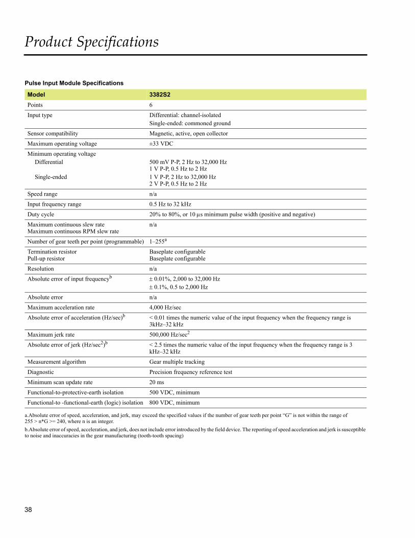
38
Product Specifications
Pulse Input Module Specifications
Model 3382S2
Points 6
Input type Differential: channel-isolatedSingle-ended: commoned ground
Sensor compatibility Magnetic, active, open collector
Maximum operating voltage ±33 VDC
Minimum operating voltageDifferential
Single-ended
500 mV P-P, 2 Hz to 32,000 Hz1 V P-P, 0.5 Hz to 2 Hz1 V P-P, 2 Hz to 32,000 Hz2 V P-P, 0.5 Hz to 2 Hz
Speed range n/a
Input frequency range 0.5 Hz to 32 kHz
Duty cycle 20% to 80%, or 10 s minimum pulse width (positive and negative)
Maximum continuous slew rateMaximum continuous RPM slew rate
n/a
Number of gear teeth per point (programmable) 1–255a
a.Absolute error of speed, acceleration, and jerk, may exceed the specified values if the number of gear teeth per point “G” is not within the range of 255 > n*G >= 240, where n is an integer.
Termination resistorPull-up resistor
Baseplate configurableBaseplate configurable
Resolution n/a
Absolute error of input frequencyb
b.Absolute error of speed, acceleration, and jerk, does not include error introduced by the field device. The reporting of speed acceleration and jerk is susceptible to noise and inaccuracies in the gear manufacturing (tooth-tooth spacing)
0.01%, 2,000 to 32,000 Hz 0.1%, 0.5 to 2,000 Hz
Absolute error n/a
Maximum acceleration rate 4,000 Hz/sec
Absolute error of acceleration (Hz/sec)b < 0.01 times the numeric value of the input frequency when the frequency range is 3kHz–32 kHz
Maximum jerk rate 500,000 Hz/sec2
Absolute error of jerk (Hz/sec2)b < 2.5 times the numeric value of the input frequency when the frequency range is 3 kHz–32 kHz
Measurement algorithm Gear multiple tracking
Diagnostic Precision frequency reference test
Minimum scan update rate 20 ms
Functional-to-protective-earth isolation 500 VDC, minimum
Functional-to -functional-earth (logic) isolation 800 VDC, minimum

39
Solid-State Relay Output ModuleEach Solid-State Relay Output Module has three isolated sets of electronics, called channels, which independently accept data from the MP associated with each channel. The channels provide input to a voter circuit which uses the voted value to drive the coil of the relay. The output portion of this module is Simplex.
The SRO Module is a non-triplicated module for use on non-critical points which are not compatible with high-side, solid-state output switches; for example, interfacing with annunciator panels. The SRO Module receives output signals from the MPs on each of three channels. The three sets of signals are voted and the voted data is used to drive the 32 individual relays. Each output has a loop-back circuit which verifies the operation of each relay switch independently of the presence of a load. Ongoing diagnostics test the operational status of the SRO Module.
SRO Modules include complete, ongoing diagnostics for each channel.
If the diagnostics detect a failure on any channel, the Fault indicator turns on and activates the system alarm. The Fault indicator identifies a channel fault, not a complete module failure. SRO Modules are guaranteed to operate properly in the presence of a single fault and may continue to operate properly with multiple faults.
SRO Modules support a hot-spare module. Each SRO Module is mechan-ically keyed to prevent improper instal-lation in a configured baseplate.
The Model 3451S2 SRO Module is compatible with the Model 2451S2 SRO Baseplate.
Model 3451S2 Solid-State Relay Output Module Specifications
Feature Specification
Points 32, commoned in pairs
Nominal input voltage ±24 V
Operational voltage range ±30 V
Maximum switching voltage ±33 V peak
Maximum switching power 15 W resistive
Maximum off-state leakage <100 A
Maximum nominal current 0.5 A per channel
Maximum over current 0.7 A per channel
Voltage drop at baseplate <0.25 V @ 0.5 A
Fuses, mounted on baseplate 1 per output, 0.75 A, fast-acting
Functional earth to protective earth isolation
500 VDC, minimum
Functional earth to functional earth (logic) isolation
800 VDC, minimum

40
Product Specifications
I/O Extender Module Kits
I/O Extender Module Kits are used to:
• Carry I/O messages from one I/O column to another
• Provide logic power terminals for each I/O column
You must connect 24 volt logic power sources to every I/O column by using an I/O Extender Module or an MP Baseplate.
Each I/O Extender Module Kit includes:
• Two I/O Extender Modules
• Three two-foot I/O Bus Cables
• One I/O or MP Interconnect Assembly
The main components on an I/O Extender Module are:
• Two 24-volt logic power input terminal blocks, each with fuse and blown-fuse indicators
• A protective earth (safety ground) terminal
• Three DB-9-pin I/O bus connectors, one per channel
In a typical Tri-GP system, a maximum of eight baseplates may be connected end-to-end in an I/O column. To extend a system beyond eight baseplates or to distribute the baseplates into multiple I/O columns, I/O Extender Modules and I/O Bus Cables are used, as shown on the figure at the right.
I/O Bus Cables
An I/O bus cable is required for each TMR channel and is terminated at each end by a male DB-9-pin connector. Various cable lengths are available.
If the I/O bus is longer than 20 feet (6 meters), the bus should be terminated by adding an I/O Bus Terminator Kit to both open ends of the system. The maximum allowable I/O bus length is 650 feet (200 meters).
I/O Extender Module
Two I/O Extender Modules Linked by I/O Bus Cables
Logic PowerTerminals
I/O Bus CablesConnectors for

41
I/O Interconnect MP InterconnectAssemblyAssembly
Top End Cap Bottom End Cap
Top End Cap Bottom End Cap
Slot
Terminal
Cover
Cover
End Caps for I/O Baseplate/I/O Extender Module
End Caps for MP Baseplate
Interconnect Assemblies
Tri-GP baseplates within a single I/O column are connected by Interconnect Assemblies that carry I/O messages and logic power across the baseplates. The MP Interconnect is connected to an I/O baseplate, and the I/O Interconnects are connected to other I/O Baseplates.
MP Interconnect Assembly
Physically, an MP Interconnect Assembly consists of a small passive PCB in a molded plastic housing with two DIN-C 96-pin male connectors. The assembly is attached to the top or bottom of an MP Baseplate in order to connect adjacent I/O Baseplates. The MP Inter-connect Assembly also is used on AI and AO HART Baseplates because they are the same size as MP Baseplates.
I/O Interconnect Assembly
Physically, an I/O Interconnect Assembly consists of a small passive PCB in a molded plastic housing with two DIN-C 96-pin male connectors. The assembly is attached to the top or bottom of an I/O baseplate in order to connect other I/O Baseplates.
Required AccessoriesThe following accessories are required to protect Tri-GP components from dust, liquids and corrosive atmospheres:
• End caps
• Terminal covers
• Slot covers
End caps protect the top and bottom of each end-of-column baseplate and serve as a card guide. They are available for both MP Baseplates and I/O Baseplates.
Terminal covers protect any terminals on a baseplate that are not connected to field wiring.
Slot covers protect unused baseplate slots.

Notes
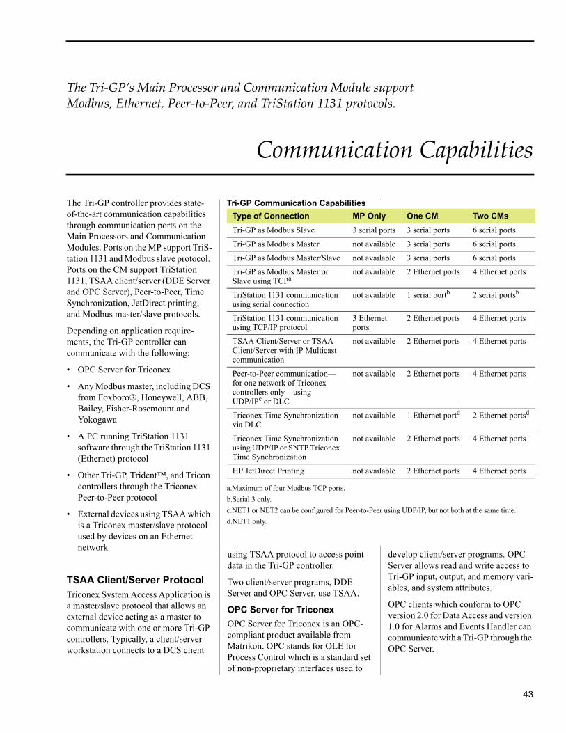
43
The Tri‐GP’s Main Processor and Communication Module support Modbus, Ethernet, Peer‐to‐Peer, and TriStation 1131 protocols.
Communication Capabilities
The Tri-GP controller provides state-of-the-art communication capabilities through communication ports on the Main Processors and Communication Modules. Ports on the MP support TriS-tation 1131 and Modbus slave protocol. Ports on the CM support TriStation 1131, TSAA client/server (DDE Server and OPC Server), Peer-to-Peer, Time Synchronization, JetDirect printing, and Modbus master/slave protocols.
Depending on application require-ments, the Tri-GP controller can communicate with the following:
• OPC Server for Triconex
• Any Modbus master, including DCS from Foxboro®, Honeywell, ABB, Bailey, Fisher-Rosemount and Yokogawa
• A PC running TriStation 1131 software through the TriStation 1131 (Ethernet) protocol
• Other Tri-GP, Trident™, and Tricon controllers through the Triconex Peer-to-Peer protocol
• External devices using TSAA which is a Triconex master/slave protocol used by devices on an Ethernet network
TSAA Client/Server ProtocolTriconex System Access Application is a master/slave protocol that allows an external device acting as a master to communicate with one or more Tri-GP controllers. Typically, a client/server workstation connects to a DCS client
using TSAA protocol to access point data in the Tri-GP controller.
Two client/server programs, DDE Server and OPC Server, use TSAA.
OPC Server for Triconex
OPC Server for Triconex is an OPC-compliant product available from Matrikon. OPC stands for OLE for Process Control which is a standard set of non-proprietary interfaces used to
develop client/server programs. OPC Server allows read and write access to Tri-GP input, output, and memory vari-ables, and system attributes.
OPC clients which conform to OPC version 2.0 for Data Access and version 1.0 for Alarms and Events Handler can communicate with a Tri-GP through the OPC Server.
Tri-GP Communication Capabilities
Type of Connection MP Only One CM Two CMs
Tri-GP as Modbus Slave 3 serial ports 3 serial ports 6 serial ports
Tri-GP as Modbus Master not available 3 serial ports 6 serial ports
Tri-GP as Modbus Master/Slave not available 3 serial ports 6 serial ports
Tri-GP as Modbus Master or Slave using TCPa
a.Maximum of four Modbus TCP ports.
not available 2 Ethernet ports 4 Ethernet ports
TriStation 1131 communication using serial connection
not available 1 serial portb
b.Serial 3 only.
2 serial portsb
TriStation 1131 communication using TCP/IP protocol
3 Ethernet ports
2 Ethernet ports 4 Ethernet ports
TSAA Client/Server or TSAA Client/Server with IP Multicast communication
not available 2 Ethernet ports 4 Ethernet ports
Peer-to-Peer communication—for one network of Triconex controllers only—using UDP/IPc or DLC
c.NET1 or NET2 can be configured for Peer-to-Peer using UDP/IP, but not both at the same time.
not available 2 Ethernet ports 4 Ethernet ports
Triconex Time Synchronization via DLC
not available 1 Ethernet portd
d.NET1 only.
2 Ethernet portsd
Triconex Time Synchronization using UDP/IP or SNTP Triconex Time Synchronization
not available 2 Ethernet ports 4 Ethernet ports
HP JetDirect Printing not available 2 Ethernet ports 4 Ethernet ports

44
Communication Capabilities
The TriStation 1131 software must be installed on a PC that is running Windows and is connected to a CM or MP port on the Tri-GP controller.
For detailed Windows version compat-ibility information, see the Product Release Notice for TriStation v4.x, available on the Invensys Global Customer Support (GCS) website.
TriStation 1131 software is compliant with the IEC 61131 International Stan-dard for Programmable Controllers.
Peer-to-Peer
Triconex Peer-to-Peer protocol allows Tri-GP, Trident, and Tricon controllers in a closed network to exchange a limited amount of process control data. The controllers in a Peer-to-Peer network can be time-synchronized with the master node (the controller with the lowest node number). Peer-to-Peer protocol supports a maximum of 31 Triconex controllers.
Upgrades to Flash ROM
The CM firmware stored in the Flash ROM can be upgraded by connecting an Ethernet port to a PC which is running the Triconex Firmware Manager.
Modbus CommunicationModbus is an industry-standard master/slave protocol that is tradition-ally used for energy management, transfer line control, pipeline moni-toring, and other industrial processes.
A Tri-GP controller can operate as a Modbus master, slave, or both. A DCS typically acts as the master while the Tri-GP controller acts as the slave. The master can also be an operator worksta-tion or any general-purpose computer programmed to support Modbus devices.
Serial ports on the MP, and serial ports and network ports on the CM, support Modbus communication.
TriStation 1131 CommunicationTriStation 1131 protocol uses TCP/IP for CM ports and DLC for MP ports to enable communication between a PC running TriStation 1131 software and a Tri-GP controller. TriStation 1131 Developer’s Workbench is used to develop, download, operate, and monitor projects for the Tri-GP controller.
For more information on OPC Server for Triconex and OPC client applica-tions, see the Matrikon Web site at www.matrikon.com.
DDE Server for Triconex
Triconex DDE Server is a Windows (2000 or XP) application that enables DDE-compliant clients to read and, if allowed, to write data to a Triconex control program. A client can read input, output, and memory variables, and system attributes.
Client applications use DDE (Dynamic Data Exchange) protocol to communi-cate with a DDE Server. Any Windows application that supports DDE protocol—such as Microsoft® Excel®—can use Triconex DDE Server.
Triconex DDE Server communicates with one or more Triconex controllers through TSAA protocol. To return data to clients, the DDE Server uses DDE protocol.
Serial Port Specifications
Mode MP CM
RTU
ASCII
RS-232
RS-485
Master
Slave
Point-to-Point
Multi-drop
Communication Interfaces
Interface MP CM
Modbus Serial Port (RS-232/RS-485)
Ethernet Port (10BaseT IEEE 802.3)
Ethernet Port (10BaseT/100BaseTX Auto-negotiable IEEE 802.3)
Attachment unit interface (AUI) for MAU
Media independent interface (MII) for MAU
Debug port

45
Easy‐to‐use developerʹs workbench allow you to develop, test and document process‐control applications for the Tri‐GP Controller
TriStation 1131 Developer’s Workbench
TriStation 1131 Developer's Work-bench is an integrated tool for devel-oping, testing, and documenting safety and critical-process control applica-tions for the Tri-GP controller. The programming methodology, user inter-face and self-documentation capabili-ties make the system superior to traditional and competing engineering tools.
This table identifies the compatibility of Tri-GP and TriStation 1131 software versions.
TriStation 1131 software is compliant with Part 3 of the IEC 61131 Interna-tional Standard for Programmable Controllers with defines programming languages.
The TriStation 1131 v4.8.0 software supports the following Windows oper-ating systems: Windows XP, Windows 7 (32-bit and 64-bit), Windows Server 2003, and Windows Server 2008 R2 (32-bit and 64-bit).
For detailed version compatibility information, see the Product Release Notice for TriStation v4.x, available on the Invensys Global Customer Support (GCS) website.
Functional Overview
TriStation 1131 software provides three editors which support these IEC 61131-3 languages:
TriStation 1131 Software
Tri-GPSystem
4.8.0 2.1.x
Features in TriStation 1131 v4.8.0 Software
These are new features in TriStation 1131 v4.8.0 software:
Support for Triconex General Purpose (Tri-GP) v2.1.x controllers
• Function Block Diagram
• Ladder Diagram
• Structured Text
An optional Triconex programming language, CEMPLE (Cause and Effect Matrix Programming Language Editor) supports the widely used Cause and Effect Matrix (CEM) methodology.
TriStation 1131 software allows you to:
• Create programs, functions, and function blocks
• Define the controller configuration
• Declare tagnames
• Test applications in an emulator
• Download and monitor applications
Example of TriStation 1131 v4.x Software Interface

46
TriStation 1131 Developer’s Workbench
Enhanced Diagnostic MonitorThe Enhanced Diagnostic Monitor is an application which monitors the hardware health of Triconex controllers and allows users to effectively troubleshoot the safety system during maintenance.
For more information on the Enhanced Diagnostic Monitor, see the online Help or printed guide included with the Enhanced Diagnostic Monitor.
Elements of a TriStation 1131 ProjectA TriStation 1131 project contains all of the elements required to implement a safety or control application in a Triconex controller. Some of these elements are automatically included in every project by TriStation 1131, while others are user-created.
Programs
A program is the highest-level execut-able logic element in a TriStation 1131 project. It is an assembly of program-ming language elements (functions, function blocks, and data variables) that work together to allow a programmable control system to achieve control of a machine or a process. Each program is uniquely identified by a user-defined type name. A TriStation 1131 project can include hundreds of programs.
Functions
A function is a logic element which yields exactly one result. Unlike a func-tion block, the data associated with a function is not retained from one evalu-ation of the function to the next. Func-tions do not have to be instanced.
Function Blocks
A function block is a logic element which yields one or more results. To use a function block in a program, an
• Triconex Library – a set of Triconex functions and function blocks that can be used with any Triconex programmable controller
• Tricon Library – a set of functions and function blocks that are specifi-cally for use with the Tricon controller
In addition to the pre-defined libraries, you can also develop your own libraries of project elements. These libraries can include programs, functions, function blocks, and data types which can be imported to other TriStation 1131 proj-ects.
Programming Languages
TriStation 1131 software includes these programming languages: Function Block Diagram, Structured Text, and Ladder Diagram. An optional language, CEMPLE, can be purchased separately.
Function Block Diagram (FBD)
Function Block Diagram is a graphical language that corresponds to circuit
instance of the function block type must first be declared. Each instance is iden-tified by a user-defined instance name. All of the data associated with a specific instance of a function block is retained from one evaluation of the function block to the next.
Data Types
A data type defines the size and charac-teristics of variables declared in a program, function or function block. Data types used by TriStation 1131 software include discrete (BOOL), analog (DINT), and real (REAL).
Libraries
TriStation 1131 software includes libraries of pre-defined functions, func-tion blocks, and data types that can be used in a project.
TriStation 1131 software includes these libraries:
• IEC 61131-3 Standard Library – a set of functions and function blocks defined by the IEC 61131-3 Stan-dard
Sample Logic in FBD, ST and LD Languages

47
diagrams. FBD elements appear as blocks that are wired together to form circuits. The wires transfer binary and other types of data between elements.
Structured Text (ST)
Structure Text is a high-level, textual programming language that is similar to PASCAL. Structured Text allows Boolean and arithmetic expressions, and programming structures such as conditional (IF…THEN…ELSE) statements. Functions and function blocks can be invoked in Structured Text.
In TriStation 1131 v4.0 software, these structures were added: arrays, structures, For Loop and Exit state-ments, CASE statement, enumerated data types, var-external, and var-temp variables.
Ladder Diagram (LD)
Ladder Diagram is a graphical language that uses a standard set of symbols for representing relay logic. The basic elements are coils and contacts which are connected by links. Links are different from the wires in FBD in that they transfer only binary data between the elements.
CEMPLE is the first automated imple-mentation of CEM, a methodology that is commonly used throughout the process-control industry and readily understood by a broad range of plant personnel. CEM diagrams are automat-ically translated into IEC 61131-3 compliant Function Block Diagrams, thereby eliminating the risks associated with manual translation from hand-drawn CEMs.
Controller Configuration
In TriStation 1131 software, the controller configuration identifies the modules in the system, communication settings, memory allocation for tagnames, and operating parameters. These configuration settings are included in the application that is downloaded to the controller.
Emulator Panel
The Emulator Panel allows you to connect to an emulator, download the control program, and test and debug the control program. The panel lists the programs, variables, and tagnames in the control program. Testing can be done by dragging variables and tagnames from the list to the monitor panel and changing the values as desired. You can specify commands to
Cause and Effect Matrix Programming Language Editor (CEMPLE)
CEMPLE is a high-level graphical language that provides a two-dimen-sional matrix in which you can asso-ciate a problem in a process with one or more corrective actions. The problem is referred to as the cause and the action as the effect. The matrix associates a cause with an effect in the intersection of the cause row and the effect column.
Sample CEM from a TriStation Project
Declaring Tagnames in a Program

48
TriStation 1131 Developer’s Workbench
run the control program without inter-vention, to run in single-step, or to halt the execution.
Controller Panel
The Controller Panel allows connection to the controller for real-time execution of the application.
TriStation 1131 Interface Options
TriStation 1131 software allows you to specify options to be used in the inter-face. For example, you can specify the drawing colors used in the program-ming editors, and editor options such as double-spacing between function block terminals. You can also specify the directory location for files.
Reports and Documentation
TriStation 1131 software includes multiple methods of sorting data and documenting project elements, both during and after project development. Printouts of user-developed function blocks and programs can be obtained on a variety of user-selected engi-neering drawing templates.
Standard reports are available to docu-ment the project configuration data. You can also create customized reports with Crystal Reports™.
Password Security
TriStation 1131 software provides a security system that defines users and their privileges with regard to editing, library changes, state changes and other operations.
Project History
An audit trail function is provided to document the history of a project and its program version changes. This detailed log keeps track of user actions and comments by automatically time-stamping critical events within a session and manually logging user comments on demand.
Annotations
Annotations can be added to constants, tagnames, and variables An annotation can be used to display descriptive text, including information specified in system and user-modifiable macros.
You can also display the value of a variable during program execution.
Comments
Comments can be added to programs, functions, and function blocks to add information about the operations.
Help Documentation
TriStation 1131 software features an online Help system which provides detailed information about the soft-ware.
Emulator Panel

49
CEMPLE is the Triconex automated implementation of the traditional CEM methodology that has been used by process control engineers for decades.
CEM Programming Language Editor
Cause and Effect Matrix (CEM) is a methodology that is commonly used in the process control industry to define alarms, emergency shutdown strate-gies, and mitigation actions. For decades, process control engineers have used manual methods such as graph paper and spreadsheet programs to identify problem conditions and corrective actions.
Automated CEMCalled CEMPLE
The traditional CEM method is time-consuming and subject to errors caused by misinterpretation of the matrix or inaccurate coding. Invensys has auto-mated the CEM process with the Cause and Effect Matrix Program-ming Language Editor, referred to as CEMPLE.
CEMPLE enables a cause and effect matrix to be used as the basis for a TriStation program.
CEMPLE Features
CEMPLE includes the following features:
• Ability to specify up to 99 causes, 99 effects, and 1,000 intersections
• Ability to invoke functions and function blocks to evaluate cause, intersection, and effect states
• Automatic conversion of matrix to Function Block Diagram language
• Customized view monitoring of active causes, intersections, and effects
• Multiple levels of undo and redo editing
CEM Editor
The CEM Editor includes the following components as shown in the figure below:
• Matrix
• FBD Network
• Variable Detail Table
Matrix
As the major component of the CEM Editor, the Matrix identifies the parts of associated with causes, effects, and intersections. The Matrix can also include functions or function blocks related to causes, effects, and intersec-tions.
FBD NetworkThe FBD Network displays the Func-tion Block Diagram (FBD) related to the cause, intersection, or effect that is selected in the matrix. It can also be used to specify properties and to invert values for variables.
Matrix rows and columns
Variable Detail Table FBD Network
CEM Editor Components
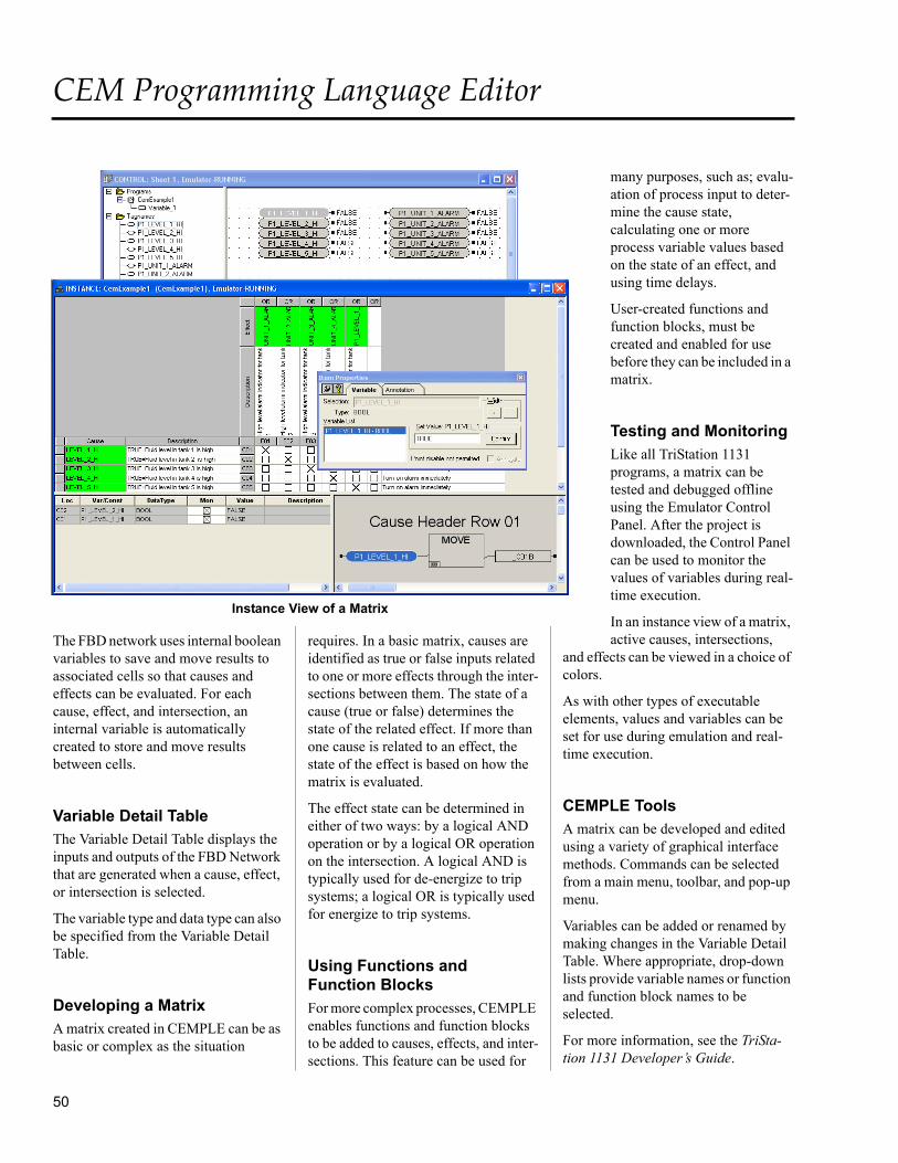
50
CEM Programming Language Editor
The FBD network uses internal boolean variables to save and move results to associated cells so that causes and effects can be evaluated. For each cause, effect, and intersection, an internal variable is automatically created to store and move results between cells.
Variable Detail TableThe Variable Detail Table displays the inputs and outputs of the FBD Network that are generated when a cause, effect, or intersection is selected.
The variable type and data type can also be specified from the Variable Detail Table.
Developing a MatrixA matrix created in CEMPLE can be as basic or complex as the situation
requires. In a basic matrix, causes are identified as true or false inputs related to one or more effects through the inter-sections between them. The state of a cause (true or false) determines the state of the related effect. If more than one cause is related to an effect, the state of the effect is based on how the matrix is evaluated.
The effect state can be determined in either of two ways: by a logical AND operation or by a logical OR operation on the intersection. A logical AND is typically used for de-energize to trip systems; a logical OR is typically used for energize to trip systems.
Using Functions and Function Blocks
For more complex processes, CEMPLE enables functions and function blocks to be added to causes, effects, and inter-sections. This feature can be used for
many purposes, such as; evalu-ation of process input to deter-mine the cause state, calculating one or more process variable values based on the state of an effect, and using time delays.
User-created functions and function blocks, must be created and enabled for use before they can be included in a matrix.
Testing and Monitoring
Like all TriStation 1131 programs, a matrix can be tested and debugged offline using the Emulator Control Panel. After the project is downloaded, the Control Panel can be used to monitor the values of variables during real-time execution.
In an instance view of a matrix, active causes, intersections,
and effects can be viewed in a choice of colors.
As with other types of executable elements, values and variables can be set for use during emulation and real-time execution.
CEMPLE ToolsA matrix can be developed and edited using a variety of graphical interface methods. Commands can be selected from a main menu, toolbar, and pop-up menu.
Variables can be added or renamed by making changes in the Variable Detail Table. Where appropriate, drop-down lists provide variable names or function and function block names to be selected.
For more information, see the TriSta-tion 1131 Developer’s Guide.
Instance View of a Matrix

51
During each scan of the TriStation 1131 project, the Main Processors examine selected discrete variables for state changes known as events.
Sequence of Events (SOE) Capability
Triconex systems support the ability to report, by exception, events that are significant in your application. This capability, called Sequence of Events (SOE), includes the following parts:
• Defining the discrete data items to be monitored through the TriStation 1131 application
• Monitoring and collecting events by the Triconex controller
• Retrieving the events from the Triconex controller using a host system
The following host systems can be used to retrieve event data:
• Triconex SOE Recorder, a Windows-based application
• An OPC client application which has implemented the Alarm and Events Handler as specified in the OPC standard version 1.0
With SOE Recorder you can:
• Collect and analyze event data
• Export event data to dBASE IV files
• Print reports with event data
The SOE data file, which is output from TriStation 1131 software, is only for use with the Triconex SOE Recorder program. This file is read by the SOE Recorder program and adds descriptive information which is associated with the tagname in the Configuration file in a TriStation 1131 project.
Preparing Your System for Event CollectionTo enable the controller to detect events, event variables and SOE blocks are identified in the TriStation 1131 project. In addition, the project must include an SOE function block that starts the event collection.
After an SOE-enabled project is down-loaded to the controller, TriStation 1131 software creates an SOE definition file that contains the SOE block definitions.
When the SOE Recorder collects an event from the controller, it obtains the tagname, alias, state name, and other information about the event variable from the SOE definition file.
The following tasks are completed in the TriStation 1131 software:
• Defining SOE blocks
• Assigning event variables to the SOE blocks
• Adding SOE function blocks to the program logic
Types of Event Variables
The types of discrete variables that can be designated as event variables include BOOL input and BOOL aliased memory variables.
Configuring SOE Blocks
An SOE block is a data structure that resides in the memory of a controller’s Main Processors. When SOE blocks are
Tri-GP Network with SOE Recorder
Triconex Controller
CM
MP
Triconex Controller
CM
MP
PC Running TriStation 1131 Software PC Running SOE Software
To DCS
NET2NET1
Triconex Controller
CM
MP
NET1

52
Sequence of Events (SOE) Capability
configured, the event variables to be detected by the controller are specified for each block.
The maximum individual block size is 20,000 events, with 60,000 events for all blocks. The block size is the amount of memory that the Main Processors reserve for recording of events.
When a block is collecting events, the Main Processors write an event entry which includes the values of event vari-ables that changed during the current scan and a time stamp.
SOE Function Blocks
SOE function blocks control and verify event collection for SOE blocks. The following function blocks are available:
• SOESTRT starts event collection
• SOESTOP stops event collection
• SOESTAT checks status of SOE blocks
• SOECLR clears status of SOE blocks
The SOESTRT function block must be added to the TriStation 1131 program to identify the SOE blocks from which events are to be collected. The other SOE function blocks are optional.
SOE Recorder
SOE Recorder can simultaneously collect event data from as many as 31 networked controllers. It queries all the controllers on the network to determine which downloaded TriStation 1131 projects include SOE blocks. If a project includes one or more SOE blocks, then SOE Recorder opens the appropriate SOE definition file and begins collecting events from the asso-ciated controller.
While the TriStation 1131 project is running, SOE Recorder can be used to analyze events online as it collects them from the controllers. Snapshots of events that cover specific periods of time before or after trips have occurred
SOE Events File
trip and y minutes after a trip, based on TriStation 1131 settings.
Time Synchronizationand Time Stamps
In a typical Peer-to-Peer network, the controllers synchronize their time with the master node (the controller with the lowest node number) within ±25 milli-seconds. A controller recognizes events on a scan basis and time-stamps each event at the beginning of the scan.
Because the scans of the various controllers on the network are not synchronized, the same event can be logged by two controllers with different time stamps. The worst-case difference is the longer scan time plus 25 milliseconds.
Each day, SOE Recorder compares its clock with the clock of each controller from which event data is being collected. If a controller’s clock is out of sync by more than five minutes, a message is displayed in the SOE message bar.
For more information about SOE Recorder, see the SOE Recorder User’s Guide.
can also be saved. SOE Recorder allows you to:
• Find events and copy them to Windows-based applications
• Filter and sort saved event data
• Specify the display of point properties for event data
• View the properties of individual events
SOE Recorder also allows event data to be exported to dBASEIV or ASCII text files, either manually or automatically. A report engine and standard report are included.
Trip Processing
A trip is a shutdown of the controlled process, or a portion of the controlled process. A TriStation 1131 project used for safety shutdown typically includes one trip variable, whose state change initiates the shutdown activities. If a project requires several variables related to trip conditions, these vari-ables must be evaluated in combination to determine the final state of the trip variable.
When a trip event occurs, SOE Recorder can automatically create a trip snapshot. This snapshot is a file of events that occurred x minutes before a

53
The symbol which represents ohm.
The symbol which represents micro.
AAbbreviation for amp.
aliasA five-digit number which identifies the data type and hardware address of a point in the Triconex controller. Alias is a convention of Modbus which is a communica-tion protocol available with Triconex communication modules.
ASICStands for Application Specific Integrated Circuit.
availabilityThe probability that the control system is operational at some instant of time.
ATEXStands for “Atomsphères Explosibles” and refers to theEuropean Union Directive 94/9/EC, which is one of anumber of approach directives developed by theEuropean Union and covers all equipment and protectivesystems intended for use in potentially explosive atmo-spheres
binAn address range of aliased variables in Triconex controllers, based on Class and Type combinations.
boardSee module.
cardSee module.
cause In CEM methodology, a cause is a problem to be solved by the matrix.
CEM Stands for Cause and Effect Matrix which is a two-dimensional matrix for the development of safety appli-cations. In this type of matrix, causes are represented by rows and effects are represented by columns.
CE MarkA type of certification by the European Union which ensures the electro-magnetic compatibility of Triconex controllers with other pieces of electrical and electronic equipment.
CEMPLEA language editor in the TriStation 1131 Developer's Workbench that allows you to develop CEMs for safety shutdown applications.
communication modulesModules that enable the Triconex controllers to commu-nicate with host computers. Invensys offers communica-tion modules with Ethernet and serial protocol.
configuration In TriStation 1131 software, the modules and settings used in a Triconex controller, including Main Processors, communication and I/O modules, field termination panels, and memory and module settings.
control programIn TriStation 1131 software, a control program is the compiled code (built from program elements and config-uration information) that is downloaded to and runs in a Triconex controller.
control system The system which governs the operation of plant, machinery or other equipment by producing appropriate instructions in response to input signals.
controllerA Triconex controller includes Main Processors, communication and I/O modules, and field termination devices.
Glossary

54
DCSStands for distributed control system, which is a system that controls a process and provides status information to an operator.
DDEStands for Dynamic Data Exchange (DDE) which is an interprocess communication mechanism provided by Microsoft Windows. Applications running under Windows can use DDE to send and receive data and instructions to and from each other.
debugThe act of locating and correcting faults: 1) one of the normal operations in software development such as editing, compiling, debugging, loading, and verifying; or 2) the identification and isolation of a faulty physical component, including its replacement or repair to return the PLC to operational status.
effectIn CEM methodology, an effect is an action that must be taken to solve a cause (problem).
eventA state change of a discrete aliased variable which has been designated for event logging. An event occurs when a variable changes from the normal state to another state.
event loggerA utility that logs, displays and prints critical events in real time, based on state changes of discrete variables in the user-written application. Proper use of an event logger warns users about dangerous conditions and printouts of events can help identify the sequence of events that led to a trip.
event variableA discrete memory variable or discrete input point that has been assigned to an SOE block.
fault toleranceThe ability to identify and compensate for failed control system elements and allow repair while continuing an assigned task without process interruption. Fault toler-ance is achieved by incorporating redundancy and fault masking.
FBDStands for Function Block Diagram which is a graphical programming language that corresponds to circuit
diagrams. Used for connective programming, FBD programs are structured by groups of interconnected elements (networks), allowing the integration of function and function blocks.
HARTHighway Addressable Remote Transducer protocol is a bi-directional industrial field communication protocol used to communicate between intelligent field instru-ments and host systems over 4–20 mA instrumentation wiring.
hostSee external host.
hot-spareA unique feature of Triconex controllers which allows spare I/O modules to be installed with automatic switch to the spare in case the primary module fails.
IEEEStands for the Institute of Electrical and Electronics Engi-neers (IEEE) which is a professional society for engi-neers.
IEC 61131-3The part of the IEC 61131 standard for programmable controllers that specifies the syntax and semantics of a unified suite of programming languages for program-mable controllers.
input poll timeThe time required by the Triconex controller to collect input data from the controlled process. Input polling is asynchronous and overlaps execution of the user-written application.
instance view In TriStation 1131 software, the Emulator Control Panel and Triconex Control Panel displays the values of anno-tated variables while a TriStation 1131 project is running. In an instance view, you can change the values of vari-ables during emulation or real-time execution.
intermittent faultA fault or error that is only occasionally present due to unstable hardware or varying software states.
intersection In CEMPLE, a cell in a matrix where a cause row inter-sects an effect column.
Glossary

55
intersection function In CEMPLE, a function or function block that can be selected from a list in the Intersection cell of a cause row and an effect row.
ISOStands for the International Organization for Standard-ization (ISO) which is a worldwide federation of national standards bodies (ISO member bodies) that promulgates standards affecting international commerce and commu-nications.
LDStands for Ladder Diagram, which is a graphical programming language that uses a set of symbols to represent relay logic. Modules are defined by their connection to a left and right power rail.
logical slotA logical slot includes two physical slots, which can house a primary module and a hot spare module.
mAbbreviation for milli.
Markov modelA generalized modeling technique which can be used to represent a system with an arbitrary number of modules, failure events, and repair events. A Markov model can be mathematically solved to produce a resultant probability.
matrix 1. A CEM program2. A traditional methodology for ESD applications which associates a problem (cause) in a process with one or more actions (effects) that must be taken to correct the problem.
moduleAn active field-replaceable unit consisting of an elec-tronic circuit assembly housed in a metal spine. Also called board or card.
MTBFStands for Mean Time Between Failure which is the expected average time between failures of a system, including the time taken to repair the system. Usually expressed in hours.
MTTFStands for Mean Time To Failure which is the expected average time to a system failure in a population of iden-tical systems. Usually expressed in hours.
MTTRStands for Mean Time To Repair which is the expected time to repair a failed system or subsystem. Usually expressed in hours.
nodeAny of the machines on a network. In this document, node usually means a Triconex controller.
node numberThe physical address of a node.
open networkA network to which an external host can be connected.
output poll timeThe time required by the Triconex controller to imple-ment the outputs generated by the user-written applica-tion in response to inputs from the controlled process.
Peer-to-PeerA protocol that allow multiple Triconex controllers on a proprietary network to exchange limited amounts of process and safety information.
program1. The set of instructions, commands, and/or directions that define the Triconex controller’s output signals in terms of input signals. 2. The act of creating such a set of instructions using the relay ladder language of the TriS-tation 1131 programming system.
protocolA set of rules describing the format used for data exchange between two entities.
reliabilityThe probability that no failure of the system will have occurred in a given period of time.
scan timeThe period of the Triconex controller’s cycle of required control functions. Scan time is composed of three elements:
• Input poll time (asynchronous with execution of the user-written application)
Glossary

56
• The time required to execute the user-written application
• Output poll time
STStands for Structured Text, which is a high-level programming language used for complex arithmetic calculations and procedures that are not easily expressed in graphical languages.
systemConsists of a set of components which interact under the control of a design.
TCP/IPStands for Transmission Control Protocol/Internet Protocol (TCP/IP) which are protocols for the Transport and Network layers of the OSI network model. TCP/IP provides reliable, sequenced data delivery.
Time SynchronizationA Triconex protocol used to establish and maintain a synchronized, network-wide time basis. Time can be synchronized with the master node in a network of Tricon, Tri-GP, or Trident controllers, with a distributed control system (DCS), or with an OPC client/server appli-cation.
transient faultA fault or error resulting from a temporary environmental condition.
TMRStands for Triple-Modular Redundant architecture, which allows Triconex controllers to achieve fault tolerance. The complete system is triplicated; each of the three iden-
tical systems is called a leg. Each leg independently executes the user-written application in parallel with the other legs.
tripA safety-related shutdown of the controlled process or a portion of the controlled process.
TriStation 1131A Windows-based application for developing and down-loading user-written applications and for performing maintenance and diagnostics.
TriStation protocolA master/slave protocol used by a TriStation 1131 appli-cation for communication with the Triconex controllers.
TÜV RheinlandTÜV stands for Technischer Überwachungs-Verein which translates to Technical Supervisory Association. In Germany, TÜV Rheinland is an authorized technical inspection agency for a wide variety of products, processes, installations, plants and equipment.
UDP/IPStands for User Datagram Protocol/Internet Protocol (UDP/IP) which are protocols for the Transport and Network layers of the OSI network model. UDP/IP provides best-effort datagram delivery.
votingA mechanism whereby each leg of a TMR system compares and corrects the data in each leg using a two-out-of-three majority voting scheme.
Glossary


