Embed Size (px)
Citation preview

8/13/2019 Technical Paper for GRP Pipe_120209
http://slidepdf.com/reader/full/technical-paper-for-grp-pipe120209 1/7
GLASS REINFORCED PLASTIC (GRP) IN THE DESIGN OF A BORE WATERTRANSFER SYSTEM
Alan Lawson1, Liz Hobart
1
1Parsons Brinckerhoff, Adelaide, SA
ABSTRACT
Glass Reinforced Plastic (GRP) was selectedfor the design of a bore water transfer pipelineto service the Jacinth-Ambrosia (J-A) mineralsands mine, currently under development inSouth Australia. The transfer pipeline is requiredfor the conveyance of untreated bore water from
a borefield to the mine process area, at a totaldistance of approximately 32 kilometres.
Although relatively new to the Australian market,particularly for large-diameter and long-distanceapplications, GRP was found to have manyadvantageous properties over “traditional” pipematerials in relation to this specific application.
GRP comprises a series of composite laminarlayers, the raw materials of which include glassfibres, polyester resins and fillers such as silica.
This paper discusses the improvement inperformance of the J-A water supplyinfastructure, as a result of selecting GRP pipefor the transfer pipeline.
INTRODUCTION
Project description
The Jacinth-Ambrosia (J-A) mineral sands minesite is located in the Eucla Basin, north-west ofCeduna in South Australia. The mine site iscurrently under development by Iluka Resourcesfor the exploitation of the mineral zircon, withproduction scheduled to commence in early2010. The design and construction of the J-Amine is being completed by an Alliance betweenIluka and Parsons Brinckerhoff (PB).
A reliable source of water is required for boththe construction and operational phases of themine. The water will be sourced from an aquiferlocated approximately 32 kilometres south-westof the mine process area. The groundwater hasbeen extensively sampled, and was found to behyper-saline and moderately acidic.
The groundwater will be extracted from a linearconfiguration of twelve production bores, and
then pumped through a collector pipelineapproximately four kilometres in length to atransfer pumping station. This collector pipelinewill be constructed from a combination of
Orientated Polyvinyl Chloride (oPVC) and GRP,and will telescope in size from DN250 to DN450.The use of oPVC was required as GRP is notreadily available in sizes less than DN375.
Water will be pumped from the transfer pumpingstation along a DN600 GRP transfer pipeline(the subject of this paper) to the process plant,where it will be stored in a 96 ML terminal
storage dam. A portion of the water will bediverted prior to discharge into the dam, andtreated using reverse osmosis (RO) technologyin order to meet the potable water demands ofthe mine.
The GRP transfer pipeline has a total length of31.25 kilometres, with an increase in elevationof approximately 75 metres between the transferpumping station and the terminal storage dam.The transfer pipeline was sized at DN600 with apressure rating of PN20 (200 metre pressurehead) in order to transfer water as efficiently as
possible, with regard to both hydraulics andexpected power costs over the design life of themine.
Taking into account the demands for bothprocess and potable water, the averageexpected flow rate during normal operatingconditions for the first seven years of miningoperations is 262 L/s. This will increase to300 L/s for the remaining life of the mine, afurther four to eight years. In addition, a flow rateof 360 L/s will be required during peakprocessing times, for a maximum period of
approximately three months per year.Prior to installation of the permanent watersupply infastructure, temporary “constructionwater” infrastructure will be installed to providewater for construction activities at the mine site.

8/13/2019 Technical Paper for GRP Pipe_120209
http://slidepdf.com/reader/full/technical-paper-for-grp-pipe120209 2/7
Appl ication of GRP
PB’s design engineers have traditionallyselected metallic pipe materials for large-diameter water conveyance projects such asmining operations. Materials used have typicallybeen steel or ductile iron, with an internal
cement mortar lining to protect against corrosionfrom poor water quality. Although plastic pipessuch as High Density Polyethylene (HDPE) andPVC are hydraulically smoother than metallicpipes, the primary reason for their exclusion inlarge diameter applications is that they are notcost-competitive with metallic pipes.
For the above reasons, the original materialspecification for the J-A transfer pipeline calledfor Ductile Iron, Cement-mortar Lined (DICL)pipe. However, the recent emergence of an Australian-based and Australian-ownedmanufacturer of GRP now provides a cost-
competitive alternative to metallic pipe materialsfor large diameter applications. As such, bothDICL and GRP were evaluated during thedetailed design phase of the project, and theadvantageous properties of GRP for thisapplication became apparent.
This paper will describe in detail the majorbenefits for the J-A project arising from theselection of GRP for the transfer pipeline. Insummary, the key benefits are as follows:
• GRP pipe is highly resistant to internal and
external corrosion from the aggressive(hyper-saline and moderately acidic)groundwater, which removed the need toapply protective coatings or sleeving;
• GRP pipe is non-conductive, and given theproximity of the transfer pipeline to a high-voltage powerline along much of itsalignment, this removed the need forearthing;
• Multiple fittings may be cast monolithicallyinto a single length of GRP pipe, therebyreducing the number of individual fittings and
flange connections required. This reducedsupply costs, as well as the cost and timeassociated with installation of the pipeline;
• The modulus of elasticity for GRP issignificantly lower than for DICL pipe,resulting in lower transient wave speedsduring water hammer events. This meantthat expensive water hammer mitigationinfrastructure was no longer required,resulting in significant cost savings;
• GRP pipe has a smoother internal surface
than DICL pipe, resulting in fewer frictionlosses along the transfer pipeline. This inturn reduced the required pumping head byapproximately 10 metres, lowering the capital
costs for the J-A transfer pumps and alsoresulting in energy savings during theiroperation;
• GRP pipe can be supplied in lengths of12 metres, which is double the standardlength of metallic pipes. Consequently fewerpipe connections were required, resulting in
faster installation time and associated costsavings;
• GRP pipe is approximately half the weight ofmetallic pipe per unit length, which results infaster transportation (as more pipe can betransported in a single load) and pipeinstallation;
• GRP pipe can be stored outdoors inaggressive environments indefinitely withoutany effect on performance. This wasadvantageous as the J-A site is located in an
arid environment, and is subject to extremeUV exposure and high temperaturefluctuations;
• The standard jointing system for GRP pipeconsists of a spigot and removable rubber-ring-joint socket coupling. This method of jointing has several advantages includingcompatibility with Australian Standard fittingsin all materials, and the ability of each spigot-coupling joint to be deflected by up to 3°(1.5° per pipe). This meant that the mostcost-effective combination of valves, fittings,
and sweep bends could be incorporated intothe design;
• The dimensions of each length of GRP pipeis checked at the factory, and those withinthe required tolerance for diameter aremarked “adjustment pipe”. These may be cuton-site to any length required, which wasuseful for accomodating minor designchanges as required by conditions on-site;
• GRP pipe is manufactured in Adelaide,South Australia. Due to its relative proximityto the J-A site, the pipe lengths could bedelivered approximately 10 weeks earlierthan DICL. This allowed the pipeline to beincorporated into the “construction water”infrastructure, thus removing the need for atemporary pipeline.

8/13/2019 Technical Paper for GRP Pipe_120209
http://slidepdf.com/reader/full/technical-paper-for-grp-pipe120209 3/7
DISCUSSION
The selection of GRP for the transfer pipelinehas resulted in numerous benefits to the J-Aproject, as previously summarised. Thesebenefits are described in greater detail below.
Non-corrositivity
One of the most important aspects to considerwith regard to the material selection for thetransfer pipeline was the quality of the water tobe conveyed. The water extracted from the J-Aborefield is characterised by high salinity(TDS > 50,000 ppm) and moderate acidity(pH 5.5). As such, the resistance of the pipelineto internal corrosion was an importantconsideration.
Testing has shown that GRP pipe can withstandlong-term exposure to aggressive internal andexternal enviornments. An investigation was
conducted by Amiantit Fiberglass Industries, aNorweigan manufacturer, who excavated a 25-year-old GRP pipe from salt-laden soils,immediately downstream of a seweragedischarge tank. This pipe was subjected to aseries of tests, after which it was found that thephysical and chemical integrity of the pipe hadnot diminished (Amiantit 2005).
The non-corrositivity of GRP negated the needfor additional protection measures againstinternal and external corrosion, such as inertcoatings and sleeving. The selection of DICL
would have required an internal calcium-aluminacement lining, as well as external protection bymeans of loose polyethylene sleeving.
The soil conditions on-site were found to beslightly alkaline, with a pH of approximately 8.5.The chemical integrity of the GRP pipes allowedthe trench backfill to be conditioned withuntreated groundwater. This was important, asthe groundwater was the only water sourceavailable on-site during installation of thetransfer pipeline This removed the need toimport water during pipeline installation. Had thepipeline been constructed from DICL, potable-quality water would have been required for soilconditioning.
Figure 1 shows the backfilled trench along theJ-A transfer pipeline being conditioned withwater to assist with soil compaction.
Figure 1: Conditioning of trench backfill with
untreated groundwater from the J-A borefield.
Non-conductivity
The pipeline alignment runs adjacent to a high-voltage powerline for much of its length. SinceGRP pipe is non-conductive, earthing of thepipe for protection against induced currents fromthe powerlines and transformers was notrequired. This would have been necessary if thetransfer pipeline was constructed from DICL.
Monolithic pipe “ specials”
A distinctive advantage of GRP pipe over DICLfor the J-A project was the ability to constructcustom-designed monolithic pipe “specials”.This allowed any configuration of required tees,elbows, reducers and flanges to be cast into asingle length of pipe. Pipe “specials” wereincorporated into the design of the transferpipeline in a range of configurations, includingisolation valve assemblies, scour tees, air valveassemblies, pipe bends and thrust flanges.
This design approach resulted in a significantreduction to the quantity of fittings, flangeconnections and thrust restraints required forinstallation of the transfer pipeline. This createdan important cost benefit to the project,attributed to a reduction in supply andinstallation costs arising from a reduction in the
number of joints required.
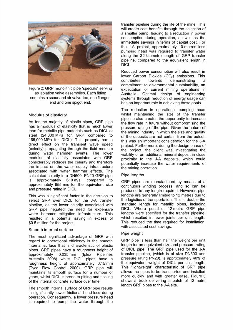
Figure 2 provides an example of a monolithicpipe “special” constructed from GRP. Thefittings shown were designed for the isolationvalve assemblies located along the transferpipeline.
8/13/2019 Technical Paper for GRP Pipe_120209
http://slidepdf.com/reader/full/technical-paper-for-grp-pipe120209 4/7
Figure 2: GRP monolithic pipe “specials” serving
as isolation valve assemblies. Each fitting
contains a scour and air valve tee, one flanged
end and one spigot end.
Modulus of elastici ty As for the majority of plastic pipes, GRP pipehas a modulus of elasticity that is much lowerthan for metallic pipe materials such as DICL orsteel (24,000 MPa for GRP compared to165,000 MPa for DICL). This property has adirect effect on the transient wave speed(celerity) propagating through the fluid mediumduring water hammer events. The lowermodulus of elasticity associated with GRPconsiderably reduces the celerity and thereforethe impact on the water supply infrastructureassociated with water hammer effects. Thecalculated celerity in a DN600, PN20 GRP pipeis approximately 610 m/s, compared toapproximately 955 m/s for the equivalent sizeand pressure rating in DICL.
This was a significant factor in the decision toselect GRP over DICL for the J-A transferpipeline, as the lower celerity associated withGRP pipe negated the need for expensivewater hammer mitigation infrastructure. Thisresulted in a potential saving in excess of$0.5 million for the project.
Smooth internal surface The most significant advantage of GRP withregard to operational efficiency is the smoothinternal surface that is characteristic of plasticpipes. GRP pipes have a roughness height ofapproximately 0.035 mm (Iplex Pipelines Australia 2008) whilst DICL pipes have aroughness height of approximately 0.15 mm(Tyco Flow Control 2000). GRP pipe willmaintains its smooth surface for a number ofyears, whilst DICL is prone to pitting and scalingof the internal concrete surface over time.
The smooth internal surface of GRP pipe resultsin significantly lower frictional head-loss duringoperation. Consequently, a lower pressure headis required to pump the water through the
transfer pipeline during the life of the mine. Thiswill create cost benefits through the selection ofa smaller pump, leading to a reduction in powerconsumption during operation, as well as theimmediate savings in terms of capital cost. Forthe J-A project, approximately 10 metres lesspumping head was required to transfer water
along the 32 kilometre length of GRP transferpipeline, compared to the equivalent length inDICL.
Reduced power consumption will also result inlower Carbon Dioxide (CO2) emissions. Thiscontributes towards demonstrating acommitment to environmental sustainability, anexpectation of current mining operations in Australia. Optimal design of engineeringsystems through reduction of energy usage canhas an important role in achieving these goals.
The reduction in operational pumping head
whilst maintaining the size of the transferpipeline also creates the opportunity to increasethe flow rate in future without compromising thepressure rating of the pipe. Given the nature ofthe mining industry in which the size and qualityof the deposits are not certain from the outset,this was an important consideration for the J-Aproject. Furthermore, during the design phase ofthe project, the client was investigating theviability of an additional mineral deposit in closeproximity to the J-A deposits, which couldpotentially increase the water requirements ofthe mining operation.
Pipe lengths
GRP pipes are manufactured by means of acontinuous winding process, and so can beproduced to any length required. However, pipelengths are generally limited to 12 metres due tothe logistics of transportation. This is double thestandard length for metallic pipes, includingDICL. Where possible, 12 metre GRP pipelengths were specified for the transfer pipeline,which resulted in fewer joints per unit length.This reduced the time required for installation,with associated cost-savings.
Pipe weight
GRP pipe is less than half the weight per unitlength for an equivalent size and pressure ratingof DICL pipe. The GRP pipe used for the J-Atransfer pipeline, (which is of size DN600 andpressure rating PN20), is approximately 40% ofthe equivalent weight of DICL per unit length.This “lightweight” characteristic of GRP pipeallows the pipes to be transported and installedmore quickly and with greater ease. Figure 3shows a truck delivering a batch of 12 metrelength GRP pipes to the J-A site.

8/13/2019 Technical Paper for GRP Pipe_120209
http://slidepdf.com/reader/full/technical-paper-for-grp-pipe120209 5/7
Figure 3: A batch of 12 metre length GRP pipes
being delivered to the J-A site. Longer pipes
require fewer joints per unit length, simplifying
the installation process.
Storage requirements GRP pipe can be stored outdoors andunsheltered for an indefinite period with noimpact to the integrity of the pipe, even in aridenvironmental conditions. The only effect issome weathering to the outer layer manifest byincreased external roughness anddiscolouration of the pipe. This has no effect onthe structural or chemical integrity of thepipeline. In contrast, DICL pipe cannot be leftexposed for any prolonged period of time. DICLpipe requires a sheltered storage area, with air-tight plugs fitted to the end of each pipe in orderto prevent the cement mortar lining from dryingout and the subsequent formation of cracks.
GRP pipe was therefore better suited to storagein the environmental conditions encounted atthe J-A site. Lengths of pipe were able to bedelivered and “strung out” adjacent to the pipealignment prior to installation, without the needfor an intermediate storage location. Figure 4shows a batch of pipes laid alongside thetrench, ready for installation.
Figure 4: Pipe lengths “strung” along thealignment, ready for installation.
Rubber-ring jointing system
The standard jointing system for GRP consistsof a spigot and rubber-ring coupling. This is aflexible jointing system which allows for amaximum deflection of 3° per joint for a DN600PN20 pipe. This feature was exploited in thedesign of the J-A transfer pipeline, which
incorporated long-radius sweeps into the designin order to change the pipeline direction. Thisapproach removed the need to incorporateadditional bends into the pipeline, thus avoidingincreased costs for additional fittings andassociated thrust restraints.
It is noted that the permissible deflection rangeof GRP pipe may not be useful for installationsin which there are tight space constraints.However, the J-A transfer pipeline was installedwithin a Miscellaneous Purpose Lease (MPL)corridor of width ranging from 50 metres to
100 metres, which was ample space. Although the standard jointing system for GRPpipes is spigot-coupling, it is possible toincorporate flanged connections as required.However, the cost of manufacturing flangedGRP pipes is high compared with DICL pipe,and as such the production of these is limited. As an alternative, GRP flange-spigot couplingscan be fitted to the end of regular spigot-endGRP pipes. This allows for greater designflexibility, as the flanged coupling can be placedat any location along the pipeline by cutting thepipe as required.
Pipeline systems are modular in configurationand often constitute a variety of pipework andmaterial constituents. The ability of GRP pipe toconnect to a variety of Australian Standardmetallic and plastic fittings was important, asthis increased the options available in theselection of valves and fittings. GRP pipe iscompatible for connection to ductile iron, PVC-U, PVC-M, PVC-O, and many asbestos cement(AC) pipe materials. Since all GRP fittings,including pipe flanges, are manufactured byhand, non-standard sizes may also be
constructed if required. This flexibility allowed agreater range of fittings and pipes to beincoprorated into the design of the J-A transferpipeline, allowing the design team to minimisecosts and lead-times for its supply.

8/13/2019 Technical Paper for GRP Pipe_120209
http://slidepdf.com/reader/full/technical-paper-for-grp-pipe120209 6/7
Adjustment p ipes
As part of its quality assurance process, thepipe manufacturer specified that at least 10% ofsupplied pipes would lie within a specifiedtolerance on diameter along their entire length.These pipes are marked “adjustment pipe” andmay be cut on-site to any length required, whichis useful for accomodating minor designchanges as required by conditions on-site. Thepipe may be cut with simple machining andchamfering of the pipe ends in order to create aspigot connection for connection to a coupling.
This feature of GRP pipe has proved useful forthe J-A project. For example, the diameter ofreceiving tanks at the transfer pumping station,and hence the location of the inlet valve, wasunknown. Consequently, the length of the finalpipe was not certain at the time of ordering, andso an “adjustment pipe” was specified such that
the length may be cut to suit on-site, thusaccomodating a range of tank sizes.
Delivery time
A final notable benefit for the J-A projectattributed to the selection of GRP for the transferpipeline relates to its delivery time. Due to therelative proximity of the manufacturing plant tothe J-A site and the expedient manufacture anddelivery, GRP pipe would be availableapproximately 10 weeks earlier than DICL pipe.This had important implications for theconstruction philosphy of the J-A transfer
pipeline.
The water supply infrastructure for the J-Aproject was constructed and utilised in twostages. Stage 1 “construction water”infastructure was to provide water required forthe construction of the mine-site, whilst Stage 2“permanent infrastructure” would provide waterfor ongoing mining operations. It was originallyenvisaged that a temporary HDPE transferpipeline would be installed as part of the“construction water” infrastructure. However, theexpedient delivery time for GRP pipe led to the
decision to install the permanent transferpipeline as part of the “construction water”infrastructure. This removed the need for thetemporary pipeline, resulting in a cost saving ofapproximately $1.4 million for the project.
Furthermore, the relative proximity of the GRPmanufacturing plant to the mine site led to areduction in transportation distance, withcorresponding reductions in both transportationcost and greenhouse gas-emissions.
CONCLUSION
GRP pipe has physical and chemicalcharacteristics that make it suitable for a rangeof applications. For the reasons discussed inthis paper, it was clear that GRP pipe was thebest option for supply of the J-A transferpipeline.
The benefits to the project resulting from theselection of GRP were significant and wideranging. The total cost savings for the projectthat is attributed to the selection of GRP hasbeen estimated at $2.8 million. This does notinclude many of the non-quantifiable aspectssuch as logistical and environmental benefits.
ACKNOWLEDGMENT
We would like to acknowledge Iluka ResourcesLimited for its permission to allow the publicationof this paper.
REFERENCES
Amiantit, GRP Division 2005. Fibre ReinforcedPlastic (FRP) Pipe in Sewerage and Saltladen or Corrosive Soils Environments. Amiantit Fibreglass Industries Ltd, Saudi Arabia.
Iplex Pipelines Australia 2008. FlowtiteEngineering Design and Installation
Guidelines for GRP Pressure and NonPressure Pipes (revision no. 8c). IplexPipelines Australia Pty Ltd, Brendale, QLD, Australia.
Tyco Flow Control 2000. Ductile Iron PipelineSystems: Design Manual (4
th edition). Tyco
Water Pty Ltd, Yennora, NSW, Australia.

8/13/2019 Technical Paper for GRP Pipe_120209
http://slidepdf.com/reader/full/technical-paper-for-grp-pipe120209 7/7