Embed Size (px)
Citation preview

T M 9 - 2 3 2 0 - 2 0 9 - 3 4 - 1
T.O. 36A12-1B-1092-2-1
TECHNICAL MANUAL
VOLUME 1 OF 2
TROUBLESHOOTINGDIRECT SUPPORT AND GENERAL SUPPORT LEVEL
2 1/2 TON, 6X6, M44A1 AND M44A2 SERIES TRUCKS
( M U L T I F U E L )
T R U C K , C A R G O : M 3 5 A 1
M 3 5 A 2 , M 3 5 A 2 C , M 3 6 A 2 ; T R U C K ,
TANK, FUEL: M49A1C, M49A2C, TRUCK, TANK,
WATER: M50A1, M50A2, M50A3; TRUCK, VAN,
SHOP: M109A2, M109A3; TRUCK, REPAIR SHOP:
M185A2, M185A3; TRUCK, TRACTOR: M275A1,
M275A2; TRUCK, DUMP: M342A2; TRUCK,
MAINTENANCE, PIPELINE CONSTRUCTION:
M 7 5 6 A 2 ; T R U C K , M A I N T E N A N C E ,
EARTH BORING AND POLESETTING: M764
DEPARTMENTS OF THE ARMY AND THE AIR FORCEMAY 1981

WARNING
WARNING
EXHAUST GASES CAN BE DEADLY
Exposure to exhaust gases produces symptoms of headache, dizziness, loss of mus-cular control, apparent drowsiness, and coma. Permanent brain damage or death canresult from severe exposure.
Carbon monoxide occurs in the exhaust fumes of fuel burning heaters and internalcombustion engines, and becomes dangerously concentrated under conditions of in-adequate ventilation. The following precautions must be observed to insure thesafety of personnel whenever fuel burning heater(s) or engine of any vehicle isoperated for maintenance purposes or tactical use.
Do not operate heater or engine of vehicle in an enclosed area unless it is adequatelyventilated.
Do not idle engine for long periods without maintaining adequate ventilation in per-sonnel compartments.
Do not drive any vehicle with inspection plates or cover plates removed unless neces-sary for maintenance purposes.
Be alert at all times during vehicle operation for exhaust odors and exposure symp-toms. If either are present, immediately ventilate personnel compartments. Ifsymptoms persist, remove affected personnel from vehicle and treat as follows:expose to fresh air; keep warm; do not permit physical exercise; if necessary,administer artificial respiration.
If exposed, seek prompt medical attention for possible delayed onset of acute lung con-gestion. Administer oxygen if available.
The best defense against exhaust gas poisoning is adequate ventilation.
Serious or fatal injury to personnel may resultif the following instructions are not complied with.
Diesel fuel is very flammable. Care must be used when choosing a place to work onfuel system. Keep truck about 50 feet away from an area where open flame, sparks,or smoking may cause a fire. Keep a fire extinguisher close by.
Fuel coming out of an injector nozzle under pressure can go through the skin. Thiscan cause blood poisoning. Keep hands away from injector nozzle when doing testprocedures.
Only properlypresent in 115
trained personnel should perform test on 115 volt system. The voltagevolt system can cause severe or fatal electric shock.

*TM 9-2320-209-34-1T.O. 36A12-1B-1092-2-1
TECHNICAL MANUAL DEPARTMENTS OF THE ARMYNO. 9-2320-209-34-1 ANDTECHNICAL ORDER THE AIR FORCENO. 36A12-1B-1092-2-1 Washington, DC, 20 May 1981
TECHNICAL MANUAL
VOLUME 1 OF 2
TROUBLESHOOTINGDIRECT SUPPORT AND GENERAL SUPPORT LEVEL
2 1/2-TON, 6X6, M44A1 AND M44A2 SERIES TRUCKS
(MULTIFUEL)
Model
Truck, Cargo
Truck, Tank, Fuel
Truck, Tank, Water
Truck, Van, Shop
Truck, Repair Shop
Truck, Tractor
Truck, Dump
Truck, Maintenance, PipelineConstruction
Truck, Maintenance, EarthBoring and Polesetter
M135AlM35A2M35A2CM36A2
M49AlCM49A2C
M50AlM50A2M50A3
M109A2M109A3
M185A2M185A3
M275A1M275A2
M342A2
M756A2
M7 64
NSN without Winch
2320-00-542-56332320-00-077-16162320-00-926-08732320-00-077-1618
2320-00-440-33492320-00-077-1631
2320-00-440-83072320-00-077-16332320-00-937-4036
2320-00-440-83132320-00-077-1636
4940-00-987-87994940-00-077-1638
2320-00-446-24792320-00-077-1640
2320-00-077-1643
NSN with Winch
2320-00-542-56342320-00-077-16172320-00-926-08752320-00-077-1619
2320-00-440-33462320-00-077-1632
2320-00-440-83052320-00-077-16342320-00-937-5264
2320-00-440-83082320-00-077-1637
4940-00-987-88004940-00-077-1639
2320-00-077-1641
2320-00-077-1644
2320-00-904-3277
2320-00-937-5980
This manual, together with TM 9-2320-209-34-2-1, 20 May 1981; TM 9-2320-209-34-2-2, 20 May 1981;
and TM 9-2320-209-34-2-3, 20 May 1981, supersedes TM 9-2320-209-34, Dated 30 March 1979.
i

TM 9-2320-209-34-1
REPORTING OF ERRORS AND RECOMMENDING IMPROVEMENTS
You can help improve this manual. If you find any mistakes or if you know of a way to improvethe procedure, please let us know. Mail your letter, DA Form 2028 (Recommended Changes toPublications and Blank Forms), or DA Form 2028-2 located in the back of this manual direct to:Commander, US Army Tank-Automotive Command, ATTN: DRSTA-MB, Warren, Michigan48090. A reply will be furnished to you.
CHAPTER 1.
CHAPTER 2.
CHAPTER 3.
CHAPTER 4.
CHAPTER 5.
CHAPTER 6.
CHAPTER 7.
CHAPTER 8.
CHAPTER 9.
TABLE OF
GENERAL INFORMATION
CONTENTS
Scope. ..... . . . . . . ... . . ....... . . . . . ...Organization . . . . . . . . . . . . . . . . . . .. . . . . . . . . . . . . . .Troubleshooting Approach . . . . . . . . . . . . . . . . . . . .
TROUBLESHOOTING APPROACHGeneral Approach . . . . . . . . . . . . . . . . . . . . . . . . . . . .Troubleshooting Index . . . . . . . . . . . . . . . . . . . . . . .Test Equipment Procedures Index . .. . . . . . . . .Troubleshooting Roadmaps . .... . .... . . . . . . . . . . Fault Symptom Index. . . . . . . . . .. . . . . . . .Sample Troubleshooting Procedure . . . . . . . . . . .
TROUBLESHOOTING INDEXGeneral . . . . . . . . . . . .... . . . . . . . . . . . . . . . . . . . . . . . . . . .Index
TEST EQUIPMENT PROCEDURE INDEXGeneral. . . ....... . ..... . . . . . . . . . . . . . . . . . .Index . . . . . . . . . . . . . . . . . . . . . . . . . . . . . . . .. . . . .
TROUBLESHOOTING ROADMAPSGeneral . . . . . . . . . . . . . . . . . . . . ..... . . . . . . .Roadmaps . . . . . . . . . . . . . . . . . . . . . . . . .
FAULT SYMPTOM INDEXESGeneral . . . . . . . . . . . . . . . . . . . . . . . . . . . . . .Indexes . . ...... . . . . . .... . . . . . . . . . . . ....
SAMPLE TROUBLESHOOTING PROCEDURESGeneral . . . . . . . . . . . . ...... . .....Sample Detailed Procedure . . . . . . . . . . . . . . . . . . . .
ENGINE SYSTEM TROUBLESHOOTINGEquipment Items Covered . . . . . . . . . . . . . . . . . . .Equipment Items Not Covered . . . . . . . . . . . . . . .
ENGINE SYSTEM TEST PROCEDURESGeneral . . . . . . . . . . . ....... . ..... ... ..Test Set-up . . . . . . . . . . . . . . . . . . . . . . . . . . . . . . . . . . . . . . .
Test Procedure . ........ . . . . . . . . . . . ...
Paragraph
1-11-21-3
2-12-22-32-42-52-6
3-13-2
4-14-2
5-15-2
6-16-2
7-17-2
8-18-2
9-19-29-3
Page
1-11-11-1
2-12-12-12-12-12-1
3-13-1
4-14-1
5-15-1
6-16-1
7-17-1
8-18-1
9-19-19-1
ii

TM 9-2320-209-34-1
CHAPTER 10.
CHAPTER 11.
CHAPTER 12.
CHAPTER 13.
CHAPTER 14.
CHAPTER 15.
CHAPTER 16.
CHAPTER 17.
CHAPTER 18.
CHAPTER 19.
CHAPTER 20.
TABLE OF CONTENTS-CONT
FUEL SYSTEM TROUBLESHOOTINGEquipment Items Covered . . . . . . . . . . . ........Equipment Items Not Covered . . . . . . . . . . . . . . . .
FUEL SYSTEM SUPPORT DIAGRAMSGeneral . . . . . . . . . . . . . . . . . .. . . . . . . . . . . . . . . . .
FUEL SYSTEM TEST PROCEDURESGeneral . . . ...... . . . . . .. . . . . . . . . . . . . . .. .Test Set-up . . . . . . . . . . . . . . ... . . . . . . . .Test Procedures
ELECTRICAL SYSTEM TROUBLESHOOTING Equipment Items Covered. . . . .. . . . . . .......Equipment Items Not Covered .. . . . . . . . . . . . . .
ELECTRICAL SYSTEM TEST PROCEDURESTest Procedures . .. . . . . . . . . . . . . . . . . . .
TRANSMISSION SYSTEM TROUBLESHOOTINGEquipment Items Covered . . . . . . . . . . . . . . . . . . . .Equipment Items Not Covered . . . . . . . . . . . . . . . .
EARTH BORING MACHINE SYSTEMTROUBLESHOOTINGEquipment Items Covered . . . . . . . . . . Equipment Items Not Covered . . . . . . . .
FRONT WINCH SYSTEM TROUBLESHOOTINGEquipment Items Covered . . . . . . . . . . . . . . . . . . . .Equipment Items Not Covered . . . . . . . . . . . . . . . .
DUMP SYSTEM TROUBLESHOOTINGEquipment Items Covered . ....... . . . . . . . . . . .Equipment Items Not Covered . . . . . . . . . . . . . . . .
REAR WINCH (M764) SYSTEMTROUBLESHOOTINGEquipment Items Covered . . . . . . . . . . . . . . . . . . . .Equipment Items Not Covered . . . . . . . . . . . . . . . .
REAR WINCH (M756A2) SYSTEMTROUBLESHOOTINGEquipment Items Covered . . . . . . . . . . . . . . . . . . . .Equipment Items Not Covered . . . . . . . . . . . . . . . .
Paragraph
10-110-2
11-1
12-112-212-3
13-113-2
14-1
15-115-2
16-116-2
17-117-2
18-118-2
19-119-2
20-120-2
Page
10-110-1
11-1
12-112-112-1
13-113-1
14-1
15-115-1
16-116-1
17-117-1
18-118-1
19-119-1
20-120-1
iii
TM 9-2320-209-34-1
TABLE OF CONTENTS-CONT
CHAPTER 1.CHAPTER 2.
Section I.Section II.Section III.Section IV.Section V.Section VI.Section VII.Section VIII.CHAPTER 3.
Section I.Section II.Section III.CHAPTER 4.
Section I.Section II.Section III.Section IV.
CHAPTER 5.Section I.Section II.
CHAPTER 6.Section I.Section II.
CHAPTER 7.Section I.
Section II.Section III.Section IV.
CHAPTER 8.Section I.Section II.
CHAPTER 9.
Section I.Section II.
CHAPTER 10.Section I.Section II.Section III.Section IV.
VOLUME 2 OF 2
Part 1 of 3
(TM 9-2320-209-34-2-1 )
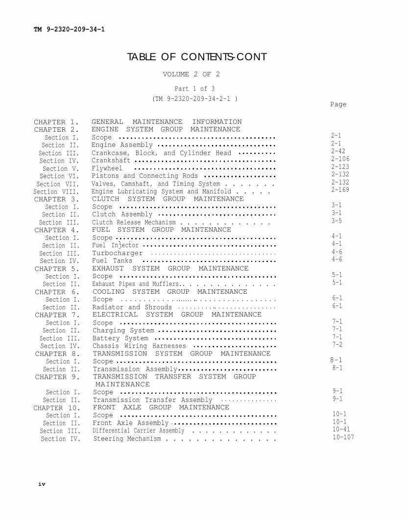
GENERAL MAINTENANCE INFORMATIONENGINE SYSTEM GROUP MAINTENANCEScopeEngine AssemblyCrankcase, Block, and Cylinder HeadCrankshaftFlywheelPistons and Connecting RodsValves, Camshaft, and Timing System . . . . . . .Engine Lubricating System and Manifold . . . . . CLUTCH SYSTEM GROUP MAINTENANCEScopeClutch AssemblyClutch Release Mechanism . . . . . . . . . . . . . FUEL SYSTEM GROUP MAINTENANCEScopeFuel InjectorTurbocharger . . . . . . . . . . . . . . . . . . . . . . . . . . . . . . . . .Fuel TanksEXHAUST SYSTEM GROUP MAINTENANCEScopeExhaust Pipes and Mufflers.. . . . . . . . . . . . . .COOLING SYSTEM GROUP MAINTENANCEScope . . . . . . . . . . . . ....... ● . . . . . . . . . . . . . . . . . .Radiator and Shrouds . . . . . . . . . ● . . . . . . . . . . . . . . . .ELECTRICAL SYSTEM GROUP MAINTENANCEScopeCharging SystemBattery SystemChassis Wiring HarnessesTRANSMISSION SYSTEM GROUP MAINTENANCEScopeTransmission AssemblyTRANSMISSION TRANSFER SYSTEM GROUPMAINTENANCEScopeTransmission Transfer Assembly . . . . . . . . . . . . . . .FRONT AXLE GROUP MAINTENANCEScopeFront Axle AssemblyDifferential Carrier Assembly . . . . . . . . . . . . .Steering Mechanism . . . . . . . . . . . . . . .
Page
2-12-12-422-1062-1232-1322-1322-169
3-13-13-5
4-14-14-64-6
5-15-1
6-16-1
7-17-17-17-2
8-18-1
9-19-1
10-110-110-4110-107
iv

TM 9-2320- 209-34-1
CHAPTER 11.Section I.
Section II.CHAPTER 12.
Section I.Section II.
Section III.Section IV.
CHAPTER 13.Section I.Section II.
CHAPTER 14.Section I.Section II.
CHAPTER 15.
Section I.Section II.
Section III.CHAPTER 16.
Section I.Section II.
CHAPTER 17.
Section I.Section II.Section III.
Section IV.Section V.Section VI.Section VII.
CHAPTER 18.
Section I.Section II.Section III.
TABLE OF CONTENTS-CONTPage
REAR AXLE GROUP MAINTENANCEScope . . . . . . . . . . . . . . . . . . . . . . . . . . . . . . . . . . . . . . . . .Rear Axle AssemblyBRAKE SYSTEM GROUP MAINTENANCEScopeHandbrake and Service Brake Assemblies . . . . . . .Hydraulic Brake System . . . . . . . . . . . . . . . . .Trailer Brake Connections and Controls . . . . . . . . .WHEEL SYSTEM GROUP MAINTENANCEScope . . . . . . . . . . . . . . . . . . . . . . . . . . . . . . . . . . . . . . .. .Wheel AssemblySTEERING SYSTEM GROUP MAINTENANCEScope . . . . . . . . . . . . . . . . . . . . . . . . . . . . . . . . . . . . . . . .Mechanical Steering Gear Assembly . .. . . . . . . . . .FRAME AND TOWING ATTACHMENTS GROUPMAINTENANCEScope . . . . . . . . . . . . . . . . . . . . . . . . . . . . . . . . . . . . . . .Frame AssemblyFifth Wheel Assembly . . . . . . . . . . . . . . . . . . . . . . . . . . .SPRINGS GROUP MAINTENANCEScope . . . . . . . . . . . . . . . . . . . . . . . . . . . . . . . . . . .Springs . . . . . . . . . . . . . . . . . . . . . . . . . . . . . . . . . . . . . . .
Part 2 of 3(TM 9-2320 -209-34-2-2 )
BODY , CAB, HOOD, AND HULL GROUPMAINTENANCEScopeHood and Cab ComponentsFenders, Running Boards, and WindshieldAssembly . . . . . . . . . . . . . . . . . . . . . . . . . . . . . . . . . . . .SeatsCargo Body Components . . . . . . . . . . . . . . . . . . . . . .Tank Body Components . . . . . . . . . . . . . . . . . . . . ..Special Purpose Body Components . .. . . . . . . . . .
Part 3 of 3(TM 9-2320 -209-34-2-3 )
WINCH , HOIST, AND POWER TAKEOFFASSEMBLIES GROUP MAINTENANCEScopeWinch and Hoist Assemblies . . . . . . . . . . . . ..Power Takeoff Assembly
11-111-1
12-112-112-712-59
13-113-1
14-114-1
15-115-115-57
16-116-1
17-117-1
17-7917-12217-14717-16517-376
18-118-118-274
v

TM 9-2320-209-34-1
CHAPTER 19.Section I.Section II.
CHAPTER 20.Section I.Section II.
CHAPTER 21.
Section I.Section II.Section III.Section IV.
APPENDIX A.INDEX .
TABLE OF CONTENTS-CONTParagraph Page
BUMPER AND GUARDS GROUP MAINTENANCEScopeBumper, Brackets, Guards, and ProtectiveDevices . . . . . . . . . . . . . . . . . . . . ..BODY ACCESSORY ITEMS GROUP MAINTENANCEScopeCanvas and Rubber Items . . . . . . . . . . . . . . .MAINTENANCE OF MATERIAL USED INCONJUNCTION WITH MAJOR ITEMSScopeWinterization KitsDeep Water Fording Kit . . . . . . . . . . . . . . . . .Special Purpose KitsREFERENCES
19-1
19-1
20-120-1
21-121-121-14021-199A-1
Index 1
vi

TM 9-2320-209-34-1
CHAPTER 1
GENERAL INFORMATION
1-1. SCOPE. This volume shows you how to do troubleshooting at the direct andgeneral support levels of maintenance. The amount of troubleshooting you can do isbased on what the Maintenance Allocation Chart says you can fix. Because of this,the only trouble symptoms you will find here are those that could be caused byfaulty things you can fix.
1-2. ORGANIZATION. This volume has the information you will need to troubleshootthe truck. Chapter 2 tells you how to use the information in the other chapters ofthis volume to find what is wrong with the truck, and what you must do to fix it.Chapter 7 has a procedure that takes you step-by-step through a sample trouble-shooting procedure and shows you how to use the information to find the trouble andfix it.
1-3. TROUBLESHOOTING APPROACH. In order to find out what is causing theproblem in the truck, you must use a good approach. A good approach just means away of doing troubleshooting so you can find the problem and not get confused or lost.The following chapter describes how you can use the materials in this volume totroubleshoot with a good approach.
1-1/( 1-2 blank)


TM 9-2320-209-34-1
CHAPTER 2
TROUBLESHOOTING APPROACH
2-1. GENERAL APPROACH. This chapter gives you instructions on how to use thetroubleshooting material to help you find and fix the trouble. In every system ofthe truck there can be faults or problems which will cause certain symptoms. Symp-toms can be such things as unusual noise, vibration, or even complete failure of asystem. This volume gives information for each system on which you can do trouble-shooting to find faults and fix them. Before you troubleshoot a system, you shouldlook at the troubleshooting indexes which will lead you to the information you need tohelp make your troubleshooting faster and easier. If you follow the instructions theright way, you will find those troubles you can fix. But, if you fix something and thetrouble is still there, it means there is more than one trouble. If this happens, startall over again to find the other trouble.
2-2. TROUBLESHOOTING INDEX. The troubleshooting index, and instructionshow to use it are in chapter 3. Go to this index first because it tells you wherefind troubleshooting roadmaps, fault symptom indexes, summary troubleshootingcharts and support diagrams for each system.
t o
2-3. TEST EQUIPMENT PROCEDURES INDEX. The test equipment procedures index,and instructions on how to use it are in chapter 4. This index tells you where to findelectrical and mechanical tests which you can use to do your troubleshooting. It alsotells you what equipment you will need to do the tests. If YOU have a STE/ICE(Simplified Test Equipment/Internal Combustion Engine) Set (NSN 4910-00-124-2554),you may use it, where applicable, to do your troubleshooting. Refer toTM 9-4910-571-12&P.
2-4. TROUBLESHOOTING ROADMAPS. Troubleshooting roadmaps for each systemare in chapter 5. If the system is made up of subsystems, these subsystems are alsoon the roadmap. Under the subsystem is a list of things which are the most likelycauses of a fault symptom in that subsystem. If you have enough skill, you cantroubleshoot these things on the truck without using the detailed troubleshootingprocedures. So if you know enough about the truck to work on your own, use theroadmap for the system with the problem before you check the fault symptom index.
2-5. FAULT SYMPTOM INDEX. Fault symptom indexes and instructions on how touse them are in chapter 6. For each system of the truck, there is an index whichgives you a list of the fault symptoms for that system. The index also tells youwhere to find the detailed troubleshooting procedures and what resources (tools/people) you need to do each procedure.
2-6. SAMPLE TROUBLESHOOTING PROCEDURE. A sample troubleshooting procedureis in chapter 7. This sample procedure will help you see the way detailed trouble-shooting procedures are to be used.
2-1/(2-2 blank)


TM 9-2320-209-34-1
CHAPTER 3
TROUBLESHOOTING INDEX
3-1. GENERAL. This chapter has a troubleshooting index which covers every systemof the truck on which you can do troubleshooting. The index tells you where to findall the other information you need to do your troubleshooting procedures.
3-2. INDEX. The troubleshooting index. (figure 3-1) is divided into five colums thatlist systems, troubleshooting roadmaps, fault symptoms, summary troubleshootingprocedures, and system support diagrams. The following breakdown tells you what isin each column.
a. System Column. This column gives a list of systems on the truck for whichtroubleshooting can be done at the direct support maintenance level.
b. Troubleshooting Roadmaps Column. This column tells you where to find thetroubleshooting roadmap for each listed system. These roadmaps are given inchapter 5.
c. Fault Symptom Index Column. This column tells you where to find the trouble-shooting fault symptom index for each listed system. Fault symptom indexes are givenin chapter 6.
d. Summary troubleshooting Procedures Column. This column tells you where tofind the summary troubleshooting procedure for each listed system. Some systems donot have summary trouble shooting procedures, so the column will be left blank forthose systems.
e. System Support Diagrams Column. This column tellsdiagrams for each listed system. Some systems do not havecolumn will be left blank for those systems.
you where to find supportsupport diagrams, so the
3-1

Figure 5-1 Table 6-1 Figure 9-1
Figure 11-1 Figure 5-2 Table 6-2
Figure 5-3 Table 6-3
Figure 5-4 Table 6-4
Figure 5-5 Table 6-5
Figure 5-6 Table 6-6
Figure 5-7 Table 6-7
Figure 5-8 Table 6-8
Figure 5-9 Table 6-9
TM 9-2320-209-34-1
F i g u r e 3 - 1 . T r o u b l e s h o o t i n g I n d e x
3-2

TM 9-2320-209-34-1
CHAPTER 4
TEST EQUIPMENT PROCEDURES INDEX
4-1. GENERAL. This chapter has a test equipment procedures index which tells youwhere to find the tests you need to do your troubleshooting.
4-2. INDEX. The test equipment procedures index is divided into three columns thatlist test equipment, tests, and figure numbers. The following breakdown tells youwhat is in each column.
a. Test Equipment Column. This column tells you what kind of equipment youneed to do your troubleshooting tests.
b. Tests Column. This column tells you what tests are given in this manual.Next to each piece of test equipment are listed the tests that you can do withthat equipment. This column also gives troubleshooting tests which can be donewithout using test equipment.
c. Figure Column. This column tells you where you can find the tests in thismanual.
4-1

FIGURE 9-1
FIGURE 12-1
TM 9-2320-209-34-1
4-2Figure 4-1. Test Equipment Procedures Index

TM 9-2320-209-34-1
CHAPTER 5
TROUBLESHOOTING ROADMAPS
5-1. GENERAL. This chapter gives troubleshooting roadmaps for every system ofthe truck for which you have detailed troubleshooting procedures. Figures 5-1through 5-9 cover all the roadmaps for the detailed procedures.
5-2. ROADMAPS. Each roadmap gives a list of things which are most likely to causea fault symptomfound to be bad
in a system or sub-system. At least one of the items listed will bewhen you do the detailed troubleshooting procedures for that system.
5-1

TM 9-2320-209-34-1
Figure 5-1. Troubleshooting Roadmap, Engine System
5 - 2Figure 5-2. Troubleshooting Roadmap, Fuel System

TM 9-2320-209-34-1
Figure 5-3. Troubleshooting Roadmap, Electrical System
5-3

TM 9-2320-209-34-1
Figure 5-4. Troubleshooting Roadmap, Transmission System
Figure 5-5. Troubleshooting Roadmap, Earth Boring Machine System
Figure 5-6. Troubleshooting Roadmap, Front Winch System
5-4

TM 9-2320-209-34-1
Figure 5-7. Troubleshooting Roadmap , M342A2 Dump System
Figure 5-8. Troubleshooting Roadmap, M764 Rear Winch System
Figure 5-9. Troubleshooting Roadmap, M756A2 Rear Winch System
5-5/(5-6 blank)


TM 9-2320-209-34-1
CHAPTER 6
FAULT SYMPTOM INDEXES
6-1. GENERAL. This chapter gives troubleshooting fault symptom indexes for everysystem of the truck for which you have detailed troubleshooting procedures. Theseindexes are in table form (tables 6-1 through 6– 9) which gives you a quick way tocheck what material you have to use to do your troubleshooting.
6-2. INDEXES. Each index is divided into columns which give you information youneed to help you do troubleshooting procedures. The following breakdown tells youwhat is in each column.
a. Subsystem Column. If the main system is divided into subsystems, the sub-systems Will be listed in this column.
b. Symptom Column. This column lists the symptoms, or problems for whichdetailed troubleshooting procedures are given.
c . Summary Column.This column tells you where to find the summary trouble-shooting procedures for each symptom.
d. Detailed Column. This column tells youshooting procedure for each symptom.
e. Persons Column. This column tells youtroubleshooting procedure.
where to find the detailed trouble-
how many people are needed to do the
f. Special Tools Column. Any tools needed to do the troubleshooting procedurewhich are not included in your common tool kit are listed in this column.
g. Standard Tools Column. A dot in this column means that tools found in yourcommon tool kit are needed to do the troubleshooting procedure.
h. Materials Column. This column tells you what materials are needed to do thetroubleshooting procedure. These materials and how they will be issued will bedecided by your maintenance officer.
i. Time Column. This column tells you how much time you will need to do thedetailed troubleshooting procedure. The time will be decided by your maintenanceofficer.
6-1

TABLE 6-1.
TABLE 6-2.
Figure 8-1
Figure 8-2
Figure 8-3
Figure 10-1
Figure 10-2
Figure 10-3
TM 9-2320-209-34-1
6-2

TABLE 6-3.
Figure 13-1
Figure 13-2
Figure 13-3
Figure 13-4
Figure 13-5
Figure 13-5
Figure 13-7
TM 9-2320-209-34-1
6-3

TABLE 6-4.
TABLE 6-5.
Figure 15-1
Figure 16-1
Figure 16-2
Figure 16-3
TM 9-2320-209-34-1
6-4

TABLE 6-6.
TABLE 6-7.
Figure 17-1
Figure 18-1
Figure 18-2
TM 9-2320-209-34-1
6-5

TABLE 6-8.
TABLE 6-9.
Figure 19-1
Figure 19-2
Figure 19-3
Figure 20-1
Figure 20-2
Figure 20-3
TM 9-2320-209-34-1
6-6

CHAPTER 7
SAMPLE TROUBLESHOOTING
TM 9-2320-209-34-1
PROCEDURE
7-1. GENERAL. This chapter gives a sample troubleshooting procedure. The purposeof the sample procedure is to help you see how detailed troubleshooting procedures,test equipment procedures, and summary troubleshooting procedures are used to findfaults in a system.
7.2. SAMPLE DETAILED PROCEDURE. (See figure 7-1.) The sample detailed pro-cedure given is the fuel system troubleshooting procedure for the symptom, STARTERMOTOR WILL NOT CRANK ENGINE. This symptom is one you will have when you tryto start your truck and certain parts on the truck are not working correctly. In eachnumbered box, instructions are given which tell you what to do, and how to do it.A large dot is placed next to the “what-to-do” instructions, and small dots next tothe “how-to-do-it” instructions.
a. Box number gives general instructions on getting the truck ready before youstart to troubleshoot.
b. Box number gives fault isolation test instructions. In this case you are toldto check the starting system circuit for loose, burned, or broken leads and connections.These tests or checks, are often referred to in detailed troubleshooting procedures tohelp you find the problem and fix it. After you do the tests or checks you read thequestion at the bottom of box number If the starter system is not okay, theanswer to the question is so you go to the next box.
c. Box number gives you a corrective action. In this case the fault is burnedor broken leads or connectors. The corrective action is what you do to fix the fault,which is to replace any burned or broken leads or connectors. If the engine stilldoesn’t start after you do this, it could mean that there are other faults in the system.When this happens, go back to the beginning of the procedure and do each step againuntil you find the other faults.
d. Sometimes the corrective actions given for a fault will tell you what to do to fixthe fault, but will not give you detailed instructions on how to fix it. Instead, youwill be told to refer to another volume in this manual for these instructions. Boxnumber is an example of this.
7-1
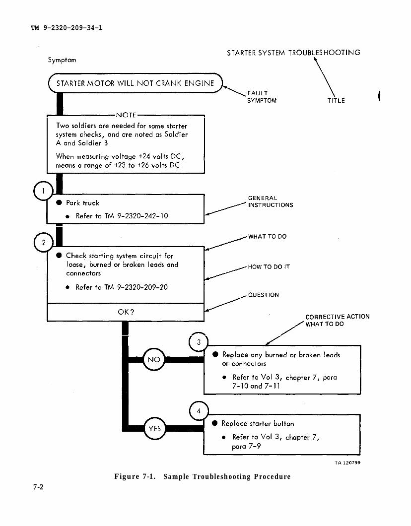
TM 9-2320-242-10
TM 9-2320-209-20
chapter 7
chapter 7
para 7-10
para 7-9
TM 9-2320-209-34-1
Figure 7-1. Sample Troubleshooting Procedure7-2

TM 9-2320-209-34-1
CHAPTER 8
ENGINE SYSTEM TROUBLESHOOTING
8-1. EQUIPMENT ITEMS COVERED. This chapter gives equipment troubleshootingprocedures for the engine system, for which there are authorized corrective main-tenance tasks at the direct support and general support maintenance level.
8-2. EQUIPMENT ITEMS NOT COVERED. All equipment items for which correctivemaintenance is authorized at the direct support and general support maintenancelevel are covered in this chapter.
8-1

TM 9-2815-210-34 Vol 2, chapter 2, para 2-19
TM 9-2320-209-10
chapter 2
TM 9-2815-210-34
TM 9-2815-210-34
TM 9-2815-210-34
TM 9-2815-210-34
chapter 2
para 2-19
para 2-19
TM 9-2320-209-34-1
8 - 2
Figure 8-1 (Sheet 1 of 4)

chapter 1 para 1-3
chapter 2
para 2-17
TM 9-2320-209-34-1
F i g u r e 8 - 1 ( S h e e t 2 o f 4 )8-3

Figure 8-1
TM 9-2320-209-34-1
8-4

Figure 8-1
TM 9-2320-209-34-1
8-5

TM 9-2320-209-34-1
Figure 8-2 ( Sheet 1 of 2 )8-6

T M 9 - 2 3 2 0 - 2 0 9 - 3 4 - 1
Figure 8-2 ( Sheet 2 of 2 )8-7

TM 9-2815-210-34
TM 9-2815-210-34
chapter 2
para 2-14
chpater 2
para 2-14
TM 9-2320-209-34-1
F i g u r e 8 - 3
8 - 8

TM 9-2320-209-34-1
CHAPTER 9
ENGINE SYSTEM TEST PROCEDURES
9-1. GENERAL. This chapter gives test procedures for the tests given in chapter 8,for the engine system .
9-2. TEST SET-UP. Instructions for setup of test equipment and parts to be testedare given before the test procedures. Illustrations are used, when needed, to showyou how to hook up the test equipment to the part to be tested.
9-3. TEST PROCEDURE. Detailed step-by-step instructions, in flow chart form, aregiven for each test. The procedure calls out the type of test and the condition of thetruck system for each part of testing. The step-by-step test will lead you to the badcomponent or to a fault symptom within a related system. Reference is made to thefault symptom index, chapter 6, if the test shows a fault in another system.
9-1

TM 9-2320-209-10
TM 9-2320-209-10
TM 9-2320-209-10
chapter 4
para 4-3
T M 9 - 2 3 2 0 - 2 0 9 - 3 4 - 1
F i g u r e 9 - 1 ( S h e e t 1 o f 2 )
9-2

TM 9-2320-209-34-1
Figure 9-1 (Sheet 2 of 2)
9-3/( 9-4 blank)


TM 9-2320-209-34-1
CHAPTER 10
FUEL SYSTEM TROUBLESHOOTING
10-1. EQUIPMENTprocedures for thetasks at the direct
10-2. EQUIPMENT
ITEMS COVERED. This chapter gives equipment troubleshootingfuel system, for which there are authorized corrective maintenancesupport and general support maintenance level.
ITEMS NOT COVERED. All equipment items for which correctivemaintenance is authorized at the direct support and general support maintenance levelare covered in this chapter.
10-1

TM 9-2320-209-34-1
Figure 10-1 ( Sheet 1 of 2 )
10-2

TM 9-2320-209-34-1
Figure 10-1 ( Sheet 2 of 2 )10-3

10-4
TM 9-2320-209-10
TM 9-2320-209-34-1
Figure 10-2 (Sheet 1 of 3)

Refer to Vol 2, chapter 4, para 4-3
Refer to TM 9-2815-210-34
Refer to TM 9-2815-210-34
Refer to Vol 2, chapter 4, para 4-3
Refer to Vol 2, chapter 4, para 4-3
TM 9-2320-209-34-1
Figure 10-2 (Sheet 2 of 3)
10-5

figure 11-1
TM 9-2815-210-34
TM 9-2815-210-34
figure 11-1
TM 9-2320-209-34-1
Figure 10-2 (Sheet 3 of 3)1 0 - 6

chapter 4 para 4-3
TM 9-2320-209-34-1
Figure 10-3 (Sheet 1 of 3)
10-7

chapter 2 para 2-21
chapter 2 para 2-21
TM 9-2320-209-34-1
10-8
Figure 10-3 (Sheet 2 of 3)

TM 9-2815-210-34
chapter 2 para 2-21
TM 9-2320-209-34-1
Figure 10-3 (Sheet 3 of 3)
10-9/(10-10 blank)


TM 9-2320-209-34-1
CHAPTER 11
FUEL SYSTEM SUPPORT DIAGRAMS
11-1. GENERAL This chapter gives the diagrams you need when doing trouble-shooting procedures in chapter 10. Figure 3-1 is a complete listing of all supportdiagrams used in this manual.
11-1

TM 9-2320-209-34-1
Figure 11-1. Fuel System Support Diagram
11-2

TM 9-2320-209-34-1
CHAPTER 12
FUEL SYSTEM TEST PROCEDURES
12-1. GENERAL. This chapter gives test procedures for the tests given in chapter10, for the fuel system.
12-2. TEST SET-UP. Instructions for setup of test equipment and parts to be testedare given before the test procedures. Illustrations are used, when needed, to showyou how to hook up the test equipment to the part to be tested.
12-3. TEST PROCEDURE. Detailed step-by-step instructions, in flow chart form,are given for each test. The procedure calls out the type of test and the conditionof the truck system for each part of testing. The step-by-step test will lead you tothe bad component or to a fault symptom within a related system. Reference is madeto the fault symptom index, chapter 6, if the test shows a fault in another system.
12-1

TM 9-2320-209-10
TM 9-2320-209-10
TM 9-2320-209-34-1
Figure 12-1
12-2

TM 9-2320-209-34-1
CHAPTER 13
ELECTRICAL SYSTEM TROUBLESHOOTING
13-1. EQUIPMENT ITEMS COVERED. This chapter gives equipment troubleshootingprocedures for the electrical system, for which there are authorized correctivemaintenance tasks at the direct support and general support maintenance level.
13-2. EQUIPMENT ITEMS NOT COVERED. All equipment items for which correctivemaintenance is authorized at the direct support and general support maintenance levelare covered in this chapter.
13-1

TM 9-2320-209-10
para 21-6 chapter 21
TM 9-2320-209-34-1
Figure 13-1 (Sheet 1 of 2)13-2

chapter 21 para 21-6
chapter 21 para 21-6
chapter 21
para 21-6
TM 9-2320-209-34-1
Figure 13-1 (Sheet 2 of 2)
13-3

TM 9-2320-209-10
para 21-6
chapter 21
TM 9-2320-209-34-1
Figure 13-2 (Sheet 1 of 3)13-4

TM 9-2320-209-20
chapter 21
para 21-6
chapter 21
para 21-6
TM 9-2320-209-34-1
13-5
Figure 13-2 (Sheet 2 of 3)

TM 9-2320-209-10
para 21-6
chapter 21
chapter 21
para 21-17
TM 9-2320-209-34-1
Figure 13-2 (Sheet 3 of 3)
13-6

TM 9-2320-209-10
chapter 21, para 21-17
TM 9-2320-209-34-1
Figure 13-3 (Sheet 1 of 6)
13-7

Refer para 21-19
chapter 21
chapter 21
para 21-17
TM 9-2320-209-34-1
Figure 13-3 (Sheet 2 of 6)
13-8

Refer chapter 21
para 21-17
TM 9-2320-209-34-1
Figure 13-3 (Sheet 3 of 6)
13-9

chapter 21
para 21-17
TM 9-2320-209-34-1
Figure 13-3 (Sheet 4 of 6)
13-10

Refer to Vol 2, chapter 21, para 21-6
chapter 21
para21-4
chapter 21
para 21-6
TM 9-2320-209-34-1
Figure 13-3 (Sheet 5 of 6)
13-11

TM 9-2320-209-34-1
Figure 13-3 (Sheet 6 of 6)
13-12

chapter 21
TM 9-2320-209-10
para 21-9
chapter 21 para 21-9
TM 9-2320-209-34-1
Figure 13-4 (Sheet 1 of 2)
13-13

chapter 21,
para 21-9
TM 9-2320-209-34-1
13-14Figure 13-4 (Sheet 2 of 2)

TM 9-2320-209-10
chapter 21
para 21-9
TM 9-2320-209-34-1
Figure 13-5 (Sheet 1 of 4)
13-15

Vol 2,
para 21-9
chapter 21
chapter 21
para 21-9
TM 9-2320-209-34-1
13-16
Figure 13-5 (Sheet 2 of 4)

chapter 21 para 21-9
chapter 21
para 21-9
TM 9-2320-209-34-1
Figure 13-5 (Sheet 3 of 4)
13-17

TM 9-2320-209-10
chapter 21
para 21-9
chapter 21
para 21-17
TM 9-2320-209-34-1
Figure 13-5 (Sheet 4 of 4)
13-18

Refer para 21-17
para 21-17
TM 9-2320-209-10
chapter 21
chapter 21
TM 9-2320- 209-34-1
Figure 13-6 (Sheet 1 of 5)
13-19

Refer para 21-17
chapter 21
TM 9-2320-209-34-1
Figure 13-6 (Sheet 2 of 5)
13-20

Refer para 21-17
Refer para 21-17
chapter 21
chapter 21
TM 9-2320-209-34-1
Figure 13-5 (Sheet 3 of 5)13-21

para 21-17
chapter 21
TM 9-2320-209-34-1
Figure 13-5 (Sheet 4 of 5)
13-22
para 21-9
chapter 21
para 21-9
chapter 21
TM 9-2320-209-34-1
Figure 13-5 (Sheet 5 of 5)
1 3 - 2 3

TM 9-2320-209-10
TM 9-2320-209-34-1
Figure 13-7 (Sheet 1 of 2)
13-24

TM 9-2320-209-10
TM 9-2320-209-20
TM 9-2320-209-10
chapter 7 para 7-11
TM 9-2320-209-34-1
Figure 13-7 (Sheet 2 of 2)
13-25/(13-26 blank)


TM 9-2320-209-34-1
CHAPTER 14
ELECTRICAL SYSTEM TEST PROCEDURES
14-1. TEST PROCEDURES. Test procedures for the electrical system consist ofprocedures for using multimeters. Refer to TM 9-2320-209-20-2 for these procedures.
14-1/(14-2 blank)


TM 9-2320-209-34-1
CHAPTER 15
TRANSMISSION SYSTEM TROUBLESHOOTING
15-1. EQUIPMENT ITEMS COVERED. This chapter gives equipment troubleshootingprocedures for the transmission system , for which there are authorized correctivemaintenance tasks at the direct support and general support maintenance level.
15-2. EQUIPMENT ITEMS NOT COVERED. All equipment items for which correctivemaintenance is authorized at the direct support and general support maintenance levelare covered in this chapter.
15-1

TM 9-2520-246-34
TM 9-2320-209-10
chapter 8
TM 9-2320-209-10
para 8-3
TM 9-2320-209-34-1
Figure 15-1
15-2

TM 9-2320-209-34-1
CHAPTER 16
EARTH BORING MACHINE SYSTEM TROUBLESHOOTING
16-1. EQUIPMENT ITEMS COVERED. This chapter gives equipment troubleshootingprocedures for the earth boring machine system , for which there are authorizedcorrective maintenance tasks at the direct support and general support maintenancelevel.
16-2. EQUIPMENT ITEMS NOT COVERED. All equipment items for which correctivemaintenance is authorized at the direct support and general support maintenancelevel are covered in this chapter.
16-1

TM 9-2320-209-10
TM 9-2320-209-10
TM 9-2320-209-10
TM 9-2320-209-10
TM 9-2320-209-10
TM 9-2320-209-34-1
Figure 16-1 (Sheet 1 of 2)
16-2

chapter 17
chapter 18
para 17-48
para 18-12
TM 9-2320-209-34-1
Figure 16-1 (Sheet 2 of 2)
1 6 - 3

chapter 17,
para 17-50 and 17-53
TM 9-2320-209-20
TM 9-2320-209-10
TM 9-2320-209-34-1
1 6 - 4
Figure 16-2 (Sheet 1 of 2)

TM 9-2320-209-10
chapter 17,
para 17-50
TM 9-2320-209-10
TM 9-2320-209-10
TM 9-2320-209-10
chapter 17 para 17-52
TM 9-2320-209-34-1
Figure 16-2 (Sheet 2 of 2)
16-5

chapter 17
para 17-49 and 17-53
TM 9-2320-209-20
TM 9-2320-209-10
TM 9-2320-209-34-1
Figure 16-3 (Sheet 1 of 2)16-6

TM 9-2320-209-34-1
Repair or replace worm drive clutch
• Refer to Vol 2, chapter 17, para 17-52
Ž Start engine
Ž Refer to TM 9-2320-209-10
Ž Move boring machine left and right
• Refer to TM 9-2320-209-10
Does boring machine move left and
r igh t?
Ž Shut down boring machine and turnoff engine
• Refer to TM 9-2320-209-10
● Repair or replace worm drive gear
Ž Refer to Vol 2, chapter 17, para 17-49
• Shut down boring machine and turnoff engine
● R e f e r t o T M 9 - 2 3 2 0 - 2 0 9 - 1 0
Figure 16-3 ( Sheet 2 of 2)
T A 1 2 0 7 8 3
16-7/(16-8 blank)


TM 9-2320-209-34-1
CHAPTER 17
FRONT WINCH SYSTEM TROUBLESHOOTING
17-1. EQUIPMENT ITEMS COVERED. This chapter gives equipment troubleshootingprocedures for the front winch system, for which there are authorized correctivemaintenance tasks at the direct support and general support maintenance level.
17-2. EQUIPMENT ITEMS NOT COVERED. All equipment items for which correctivemaintenance is authorized at the direct support and general support maintenancelevel are covered in this chapter.
17-1

chapter 18
TM 9-2320-209-10
TM 9-2320-209-10
TM 9-2320-209-20
TM 9-2320-209-10
TM 9-2320-209-10
TM 9-2320-209-10
TM 9-2320-209-10
para 18-13
TM 9-2320-209-34-1
17-2Figure 17-1 (Sheet 1 of 2)

para 18-3
chapter 18
chapter 18
TM 9-2320-209-20
TM 9-2320-209-10
TM 9-2320-209-10
chapter 18
para 18-3
para 18-3
TM 9-2320-209-34-1
Figure 17-1 (Sheet 2 of 2)17-3/(17-4 blank)


TM 9-2320-209-34-1
CHAPTER 18
DUMP SYSTEM (M342A2) TROUBLESHOOTING
18-1. EQUIPMENT ITEMS COVERED. This chapter gives equipment troubleshootingprocedures for the dump system, for which there are authorized corrective main-tenance tasks at the direct support and general support maintenance level.18-2. EQUIPMENT ITEMS NOT COVERED. All equipment items for which correctivemaintenance is authorized at the direct support and general support maintenance levelare covered in this chapter.
18-1

chapter 18
TM 9-2320-209-10
para18-7
TM 9-2320-209-34-1
Figure 18-1 (Sheet 1 of 2)18-2

chapter 18
chapter 18
chapter 18
TM 9-2320-209-10
TM 9-2320-209-10
TM 9-2320-209-10
para 18-10
para 18-9
para 18-8
para 18-10
chapter 18
TM 9-2320-209-34-1
18-3
Figure 18-1 (Sheet 2 of 2)

TM 9-2320-209-10
chapter 18
TM 9-2320-209-10
TM 9-2320-209-10
TM 9-2320-209-10
para 18-10
TM 9-2320-209-10
chapter 18
para 18-10
TM 9-2320-209-34-1
Figure 18-2 (Sheet 1 of 2)
18-4

chapter 18
TM 9-2320-209-10
TM 9-2320-209-10
para 18-8
TM 9-2320-209-34-1
Figure 18-2 (Sheet 2 of 2)
18-5/(18-6 blank)


TM 9-2320-209-34-1
CHAPTER 19
REAR WINCH (M764) SYSTEM TROUBLESHOOTING
19-1. EQUIPMENT ITEMS COVERED. This chapter gives equipment troubleshootingprocedures for the M764 rear winch system, for which there are authorized correctivemaintenance tasks at the direct support and general support maintenance level.
19-2. EQUIPMENT ITEMS NOT COVERED. All equipment items for which correctivemaintenance is authorized at the direct support and general support maintenance levelare covered in this chapter.
19-1

TM 9-2320-209-20
chapter 18
TM 9-2320-209-10
TM 9-2320-209-10
TM 9-2320-209-10
TM 9-2320-209-20
TM 9-2320-209-10
TM 9-2320-209-10
TM 9-2320-209-10
para 18-16
TM 9-2320-209-34-1
19-2Figure 19-1 (Sheet 1 of 2)

chapter 18
TM 9-2320-209-10
chapter 18
TM 9-2320-209-10
chapter 18
TM 9-2320-209-20
TM 9-2320-209-10
para 18-6
para 18-12
para 18-5
TM 9-2320-209-34-1
Figure 19-1 (Sheet 2 of 2)19-3

TM 9-2320-209-10
TM 9-2320-209-10
TM 9-2320-209-10
chapter 18
TM 9-2320-209-10
TM 9-2320-209-10
TM 9-2320-209-10
para 18-5
TM 9-2320-209-34-1
19-4Figure 19-2 (Sheet 1 of 2)

chapter 18
TM 9-2320-209-10
TM 9-2320-209-10
para 18-5
TM 9-2320-209-10
chapter 18
para 18-5
TM 9-2320-209-34-1
Figure 19-2 (Sheet 2 of 2)19-5

TM 9-2320-209-10
TM 9-2320-209-10
TM 9-2320-209-10
para 18-5
TM 9-2320-209-10
TM 9-2320-209-10
TM 9-2320-209-10
chapter 18
TM 9-2320-209-34-1
Figure 19-3 (Sheet 1 of 2)
19-6

para 18-5
chapter 18
TM 9-2320-209-10
TM 9-2320-209-10
TM 9-2320-209-10
chapter 18
TM 9-2320-209-10
para 18-5
TM 9-2320-209-34-1
Figure 19-3 (Sheet 2 of 2)19-7/(19-8 blank)


TM 9-2320-209-34-1
CHAPTER 20
REAR WINCH (M756A2) SYSTEM TROUBLESHOOTING
20-1. EQUIPMENT ITEMS COVERED. This chapter gives equipment troubleshootingprocedures for the M756A2 rear winch system, for which there are authorized correc-tive maintenance tasks at the direct support and general support maintenance level.20-2. EQUIPMENT ITEMS NOT COVERED. All equipment items for which correctivemaintenance is authorized at the direct support and general support maintenance levelare covered in this chapter.
20-1

TM 9-2320-209-10
TM 9-2320-209-10
TM 9-2320-209-10
TM 9-2320-209-10
TM 9-2320-209-20
TM 9-2320-209-10
TM 9-2320-209-10
TM 9-2320-209-10
chapter 18 para18-16
chapter 18 para 18-4
chapter 18
para 18-4
TM 9-2320-209-34-1
Figure 20-1
20-2

TM 9-2320-209-10
TM 9-2320-209-10
TM 9-2320-209-10
TM 9-2320-209-10
para 18-4
TM 9-2320-209-10
TM 9-2320-209-10
TM 9-2320-209-10
chapter 18
TM 9-2320-209-34-1
Figure 20-2 (Sheet 1 of 2)
20-3

TM 9-2320-209-10
TM 9-2320-209-10
TM 9-2320-209-10
para 18-4
chapter 18 para 18-4
chapter 18
TM 9-2320-209-34-1
Figure 20-2 (Sheet 2 of 2)
20-4

TM 9-2320-209-10
TM 9-2320-209-10
TM 9-2320-209-10
TM 9-2320-209-10
TM 9-2320-209-20
TM 9-2320-209-10
TM 9-2320-209-10
TM 9-2320-209-34-1
2 0 - 5Figure 20-3 (Sheet l of 2)

TM 9-2320-209-10
TM 9-2320-209-10
TM 9-2320-209-10
para 18-4
TM 9-2320-209-10
chapter 18
chapter 18 para 18-4
TM 9-2320-209-34-1
Figure 20-3 (Sheet 2 of 2)
20-6

By Order of the Secretaries of the Army and the Air Force:
TM 9-2320-209-34-1
E.C. MEYERGeneral, United States Army
Chief of StaffOfficial:
J.C. PENNINGTONMajor General, United States Army
The Adjutant General
LEW ALLEN, JR., General, USAFChief of Staff
Official:
VAN L. CRAWFORD, JR., Colonel, USAFDirector of Administration
Distribution:
To be distributed in accordance with DA FORM 12-38, Direct Support and General SupportMaintenance requirements for 2-1/2 Ton Truck Cargo, and 2-1/2 Ton Truck Van, etc.