Embed Size (px)
Citation preview
TROUBLESHOOTING and
TECHNICAL REFERENCE GUIDE
Volume 1
4th Edition
January 30, 2007 Compiled and edited by Stephen Gragert
World Wide Technical Support Trainer
*****************************************************************************************
This document and information herein is the property of Engenio Storage Group, LSI Logic, Inc. and all unauthorized use and reproduction is prohibited.
Copyright © 1999-2007 by Engenio Storage Group, LSI Logic, Inc. All rights reserved. Printed in USA. Engenio Storage Group, LSI Logic, Inc. is an active member of the RAID Advisory Board, an industry consortium dedicated to fostering
the understanding and utilization of RAID technology. Engenio Storage Group, LSI Logic, Inc. is an active member of the Technical Support Alliance Network.

This page intentionally left blank
Troubleshooting and Technical Reference Guide - Volume 1
Table of Contents
1. Introduction _______________________________________________________________ 5
2. Comparison of Commands Before and After 06.16 ________________________________ 6
3. Shell Commands - Usage and Explanation _____________________________________ 11 3.1 Starting the Shell ______________________________________________________________ 11 3.2 Shell Commands _______________________________________________________________ 12
3.2.1 Quick Overview of Commands _______________________________________________________ 12 3.2.2 Drive/VOLUME Status Commands ____________________________________________________ 13
3.2.2.01 cfgPh <ch,id> _________________________________________________________________ 13 3.2.2.02 cfgPbDev <ch,id,volume> _______________________________________________________ 13 3.2.2.03 cfgPhy <ch,id> ________________________________________________________________ 14 3.2.2.04 cfgPhyList____________________________________________________________________ 16 3.2.2.05 cfgUnit <volume>______________________________________________________________ 16 3.2.2.06 cfgUnitList ___________________________________________________________________ 19 3.2.2.07 ghsList ______________________________________________________________________ 19 3.2.2.08 vdAll <cmd>__________________________________________________________________ 20 3.2.2.09 vdShow <volume> _____________________________________________________________ 20 3.2.2.10 cfgShow _____________________________________________________________________ 23 3.2.2.11 cfgSundTab___________________________________________________________________ 23 3.2.2.12 cfgDd <ch,id>_________________________________________________________________ 24
3.2.3 Drive/VOLUME Modify Commands___________________________________________________ 24 3.2.3.01 isp cfgPrepareDrive,0x<phydev>__________________________________________________ 24 3.2.3.02 isp cfgFailDrive,0x<devnum> ____________________________________________________ 24 3.2.3.03 isp cfgReplaceDrive,0x<devnum> _________________________________________________ 24 3.2.3.04 isp cfgSetDevOper,0x<devnum> __________________________________________________ 24 3.2.3.05 isp cfgDelVdisk,<volume>_______________________________________________________ 24 3.2.3.06 isp cfgRefreshVdisk,<volume>,<devnum of optimal drive>,0 ___________________________ 24 3.2.3.05 incrementCfgGenerationNumber __________________________________________________ 24
3.2.4 Controller/RDAC Status Commands ___________________________________________________ 25 3.2.4.01 arrayPrint ____________________________________________________________________ 25 3.2.4.02 arrayPrintSummary_____________________________________________________________ 26
3.2.5 Controller/RDAC Modify Commands __________________________________________________ 27 3.2.5.01 isp rdacMgrSetModeActivePassive ________________________________________________ 27 3.2.5.02 isp rdacMgrSetModeDualActive __________________________________________________ 27 3.2.5.03 isp rdacMgrAltCtlFail___________________________________________________________ 27 3.2.5.04 isp rdacMgrAltCtlResetRelease ___________________________________________________ 27 3.2.5.05 acsAutoCodeSync______________________________________________________________ 27
3.2.5.06 isp rdacMgrAltCtlReset ___________________________________________________________ 27 3.2.6 Other Useful Shell Commands and Procedures ___________________________________________ 27
3.2.6.01 cacheAnalyze _________________________________________________________________ 27 3.2.6.02 ccmStateAnalyze ______________________________________________________________ 28 3.2.6.03 memShow & memoryShow ______________________________________________________ 29 3.2.6.04 moduleList ___________________________________________________________________ 30 3.2.6.05 moduleShow __________________________________________________________________ 32 3.2.6.06 spmShow_____________________________________________________________________ 32 3.2.6.07 spmShowMaps ________________________________________________________________ 34 3.2.6.08 getObjectGraph_MT 8 __________________________________________________________ 35 3.2.6.09 mhmPrintPeanutStatus __________________________________________________________ 45 3.2.6.10 mhmPrintFredStatus ____________________________________________________________ 45 3.2.6.11 svlShow _____________________________________________________________________ 45
EngenioStorage Group LSI Logic, Inc.
i
Troubleshooting and Technical Reference Guide - Volume 1
3.2.6.12 avtHostShow__________________________________________________________________ 46 3.2.7 netCfgShow and netCfgSet___________________________________________________________ 46
3.2.7.1 Troubleshooting _________________________________________________________________ 49 3.2.7.2 Common Network Problems _______________________________________________________ 51
3.2.8 writeZerosFlag ____________________________________________________________________ 51 3.2.8.01 Turning writeZerosFlag On ______________________________________________________ 51 3.2.8.02 Turning writeZerosFlag Off ______________________________________________________ 52
3.2.9 Reviving a Dead Volume ____________________________________________________________ 53 3.2.10 Deleting a Host Port from the Shell ____________________________________________________ 53 3.2.11 Volume is not accessible from the host _________________________________________________ 54 3.2.12 Drive path redundancy lost___________________________________________________________ 54 3.2.13 How to retrieve the Major Event Log (MEL) from the shell _________________________________ 55 3.2.14 Adding drives that have a previous DacStor on them ______________________________________ 55 3.2.15 Changing the modification priority_____________________________________________________ 56 3.2.16 How to identify a drive from the shell __________________________________________________ 56 3.2.17 How to create and delete a Global Hot Spare from the shell _________________________________ 56 3.2.18 Monitoring and Stopping Media Scan from the shell_______________________________________ 56 3.2.19 hdd 90 ___________________________________________________________________________ 57 3.2.20 Turning tracing on and repairing bad blocks _____________________________________________ 57 3.2.21 Clearing the Storage Partition Management Region________________________________________ 58
4. Fibre Channel Driver Commands_____________________________________________ 59 4.1 Overview _____________________________________________________________________ 59
4.1.1 Cables ___________________________________________________________________________ 59 4.1.2 Watchdog Timer ___________________________________________________________________ 59
4.2 Debugging Problems with the Fibre Channel Interface _______________________________ 59 4.3 The fc commands ______________________________________________________________ 60
4.3.1 fc <Usage> _______________________________________________________________________ 60 4.3.1.01 fc 2 (Fibre Channel History) _____________________________________________________ 61 4.3.1.02 fc 3 (list of open exchanges) _____________________________________________________ 64 4.3.1.03 fc 5 (Quick Status) _____________________________________________________________ 64 4.3.1.04 fc 6 (Frame Mgr Status Log) _____________________________________________________ 65 4.3.1.05 fc 7 (Check Condition Log) ______________________________________________________ 66 4.3.1.06 fc 8 (Event Log) _______________________________________________________________ 66 4.3.1.07 fc 10 (host login list) ___________________________________________________________ 67 4.3.1.08 fc 10,10,3 (detailed host login list) ________________________________________________ 68 4.3.1.09 fc 12 (firmware versions)________________________________________________________ 70 4.3.1.10 fc 20 (Tachyon Line-level Statistics)_______________________________________________ 70 4.3.1.11 Clear Counters (fc90) ___________________________________________________________ 72 4.3.1.12 Clearing the accumulated totals and the trace (fc 91)___________________________________ 72 4.3.1.13 fc 100 (World Wide Name change information) ______________________________________ 72 4.3.1.14 fcNames (How to get worldwide names for all the channels) ____________________________ 72 4.3.1.15 fc101 ________________________________________________________________________ 73 4.3.1.16 fc111 ________________________________________________________________________ 73 4.3.1.17 fcAll (How to get an overall status)________________________________________________ 73 4.3.1.18 fcTail (Display last few entries of each log) _________________________________________ 74 4.3.1.19 fcHosts ______________________________________________________________________ 74 4.3.1.20 fcDump ______________________________________________________________________ 78
4.3.2 fcDevs___________________________________________________________________________ 78 4.3.2.01 fcDevs 1 - All Views by View Type (Active) ________________________________________ 78 4.3.2.02 fcDevs 2 - Inquiry View _________________________________________________________ 79 4.3.2.03 fcDevs 3 – Names View _________________________________________________________ 80 4.3.2.04 fcDevs 4 – Path View ___________________________________________________________ 81 4.3.2.05 fcDevs 5 – Common Names View _________________________________________________ 82 4.3.2.06 fcDevs 6 – Bufs View___________________________________________________________ 83
EngenioStorage Group LSI Logic, Inc.
ii
Troubleshooting and Technical Reference Guide - Volume 1
4.3.2.07 fcDevs 7 - Detail (All Luns) View and fcDevs 8 - Detail (Active Luns Only) View __________ 83 4.3.2.08 fcDevs 9 - All Views by LUN Device ______________________________________________ 83 4.3.2.09 fcDevs 10 - All Views by View Type (Detailed) ______________________________________ 83 4.3.2.10 fcDevs 11 - RLS View __________________________________________________________ 84 4.3.2.11 fcDevs 12 - Devices with any Errors _______________________________________________ 89 4.3.2.12 fcDevs 13 - Devices with RW Errors Returned by VDD ________________________________ 89 4.3.2.13 fcDevs 14 - Devices with Major Errors _____________________________________________ 90 4.3.2.14 hddDump ____________________________________________________________________ 90
5. ION Driver Commands _____________________________________________________91 5.1 Overview _____________________________________________________________________ 91
5.1.1 ion Commands ____________________________________________________________________ 91 5.1.1.01 ionHelp ______________________________________________________________________ 91 5.1.1.02 ch and chall___________________________________________________________________ 93 5.1.1.03 lu and luall ___________________________________________________________________ 94 5.1.1.04 iditn and iditnall _______________________________________________________________ 95 5.1.1.05 tditn and tditnall _______________________________________________________________ 97 5.1.1.06 ionShowInquiry _______________________________________________________________ 97 5.1.1.07 ionShow 12 ___________________________________________________________________ 98 5.1.1.08 ionShow 99 ___________________________________________________________________ 98 5.1.1.09 Controller I/O Breakdown _______________________________________________________ 98
5.2.1 hids Commands ___________________________________________________________________ 99 5.2.1.01 hids 104 or ‘h’________________________________________________________________ 100 5.2.1.02 hids 2_______________________________________________________________________ 101 5.2.1.03 hids 32______________________________________________________________________ 101 5.2.1.04 hids 77______________________________________________________________________ 102 5.2.1.05 hids 108_____________________________________________________________________ 103
5.3.1 fcn Commands ___________________________________________________________________ 103 5.3.1.01 fcnHelp _____________________________________________________________________ 103 5.3.1.02 fcnShow ____________________________________________________________________ 104 5.3.1.03 fcnShow 11 and fcnRls_________________________________________________________ 105 5.3.1.02 fcnChannelReport and fcnCMClearCounts _________________________________________ 106
5.4 Serially Attached SCSI (SAS) _________________________________________________________ 107 5.4.1.01 sasHelp _____________________________________________________________________ 107 5.4.1.02 sasShowChannels _____________________________________________________________ 108 5.4.1.03 sasShowMiswires _____________________________________________________________ 108 5.4.1.04 sasShowPhyErrStats ___________________________________________________________ 108 5.4.1.05 sasShowDevices ______________________________________________________________ 109 5.4.1.06 sasShowExpanders ____________________________________________________________ 110 5.4.1.07 sasShowAllExpanders _________________________________________________________ 111
5.5 Subystem Monitor (SSM)_____________________________________________________________ 111 5.5.1.01 ssmHelp ____________________________________________________________________ 112 5.5.1.02 ssmShow____________________________________________________________________ 113 5.5.1.03 ssmShowEnclosures ___________________________________________________________ 114 5.5.1.04 ssmAudibleAlarm _____________________________________________________________ 116 5.5.1.05 ssmIdentifyDrive _____________________________________________________________ 116
Appendix_____________________________________________________________________117 A.1 Destination Driver MEL Events Decoder _________________________________________ 117
A.1.1 FIBRE DRIVE-SIDE INTERFACES ONLY ___________________________________________ 117 A.2 LOOP-ID to ALPA conversion table_____________________________________________ 120 A.3 Engenio Host Sense Data and ASC/ASCQ codes ___________________________________ 121
A.3.1 Host Sense Data __________________________________________________________________ 121 A.3.1.01 Request Sense Data Format _____________________________________________________ 121
EngenioStorage Group LSI Logic, Inc.
iii
Troubleshooting and Technical Reference Guide - Volume 1
A.3.1.02 Incorrect Length Indicator (ILI) - Byte 2 ___________________________________________ 121 A.3.1.03 Sense Key - Byte 2 ____________________________________________________________ 122 A.3.1.04 Information Bytes - Bytes 3-6 ___________________________________________________ 122 A.3.1.05 Additional Sense Length - Byte 7_________________________________________________ 122 A.3.1.06 Command Specific Information - Bytes 8-11________________________________________ 122 A.3.1.07 Additional Sense Codes - Bytes 12-13 _____________________________________________ 122 A.3.1.08 Field Replaceable Unit Code - Byte 14 ____________________________________________ 122 A.3.1.09 Sense Key Specific Bytes - Bytes 15-17____________________________________________ 124 A.3.1.10 Recovery Actions - Bytes 18-19__________________________________________________ 124 A.3.1.11 Total Number Of Errors - Byte 20 ________________________________________________ 124 A.3.1.12 Total Retry Count - Byte 21 _____________________________________________________ 124 A.3.1.13 ASC/ASCQ Stack - Bytes 22-25 _________________________________________________ 124 A.3.1.14 Additional FRU Information - Bytes 26-33 _________________________________________ 124 A.3.1.15 Error Specific Information - Bytes 34-36 ___________________________________________ 128 A.3.1.16 Error Detection Point - Bytes 37-40 _______________________________________________ 128 A.3.1.17 Original CDB - Bytes 41-50 _____________________________________________________ 128 A.3.1.18 Host ID - Byte 51 _____________________________________________________________ 128 A.3.1.19 Host Descriptor - Bytes 52-53 ___________________________________________________ 128 A.3.1.20 Controller Serial Number - Bytes 54-69____________________________________________ 128 A.3.1.21 Array Software Revision - Bytes 70-73 ____________________________________________ 128 A.3.1.22 LUN Number - Byte 75 ________________________________________________________ 128 A.3.1.23 LUN Status - Byte 76 __________________________________________________________ 128 A.3.1.24 Drive Software Revision - Bytes 79-82 ____________________________________________ 129 A.3.1.25 Drive Product ID - Bytes 83-98 __________________________________________________ 129 A.3.1.26 Array Power-up Status - Bytes 99-100_____________________________________________ 129 A.3.1.27 RAID Level - Byte 101_________________________________________________________ 129 A.3.1.28 Drive Sense Identifier - Bytes 102-103 ____________________________________________ 129 A.3.1.29 Drive Sense Data - Bytes 104-135 ________________________________________________ 129 A.3.1.30 Sequence Number - Bytes 136-139 _______________________________________________ 129 A.3.1.31 Date and Time Stamp - Bytes 140-155_____________________________________________ 129
A.3.2 Sense Codes _____________________________________________________________________ 129 A.3.2.1 Sense Keys __________________________________________________________________ 129 A.3.2.2 Additional Sense Codes And Qualifiers ____________________________________________ 130
A.4 Industry Standard ASC/ASCQ Codes _________________________________________144 A.4.1 SCSI ASC/ASCQ Table Format Explanation ____________________________________ 144 A.4.2 SCSI ASC/ASCQ Assignments ________________________________________________ 144
A.5 SATA ASC/ASCQ Codes ___________________________________________________159
Subject Index – Volume 1 _______________________________________________________ 160
Subject Index – Volume 2 _______________________________________________________ 162
EngenioStorage Group LSI Logic, Inc.
iv
Troubleshooting and Technical Reference Guide - Volume 1
1. Introduction
This document is intended for Engenio, OEM, Reseller Engineers and Technical Support personnel as a reference source when working with Engenio based storage systems. It includes useful commands to determine controller, drive and volume/LUN status; the usage and meaning of general debugging commands; and explanations of commands for analyzing controller behavior. Not all of the available commands are listed in this document, only the most common and/or useful commands.
Additional reference material has been included such as command line interface usage, scripting, host specific information, white papers and reference tables plus any other documents that may be of benefit to support personnel.
This document is divided into two volumes. The first volume covers shell commands for firmware versions 04.xx to 06.15 plus items mentioned in the previous paragraph. Some of the shell commands may still be used at firmware levels above 06.15. The commands listed in Volume 1 that are still used with the newer code levels, as well as some of the replacement commands of the newer code levels, are listed in a chart in Volume 2, Chapter 2. Also in Volume 2 are shell commands and other items unique to firmware beginning with 06.16. At the end of both volumes is an index of both Volume 1 and Volume 2 for easy of use and cross-reference purposes.
Any suggestions for additions, deletions, changes, comments and/or remarks are welcome and should be forwarded to Steve Gragert ([email protected]), Engenio Storage Group, LSI Logic, Inc. Important Note: THE INFORMATION CONTAINED IN THIS DOCUMENT, THE COMMANDS SHOWN, AND THE CODE IMPLEMENTATION IS SUBJECT TO CHANGE WITHOUT NOTICE. THIS IS FOR REFERENCE ONLY AND DOES NOT, NOR INTENED TO, COVER ALL PROBLEMS AND/OR METHODS OF MAINTENANCE. THIS DOCUMENT IS NOT INTENDED FOR END-USERS.
EngenioStorage Group LSI Logic, Inc.
5
Troubleshooting and Technical Reference Guide - Volume 1
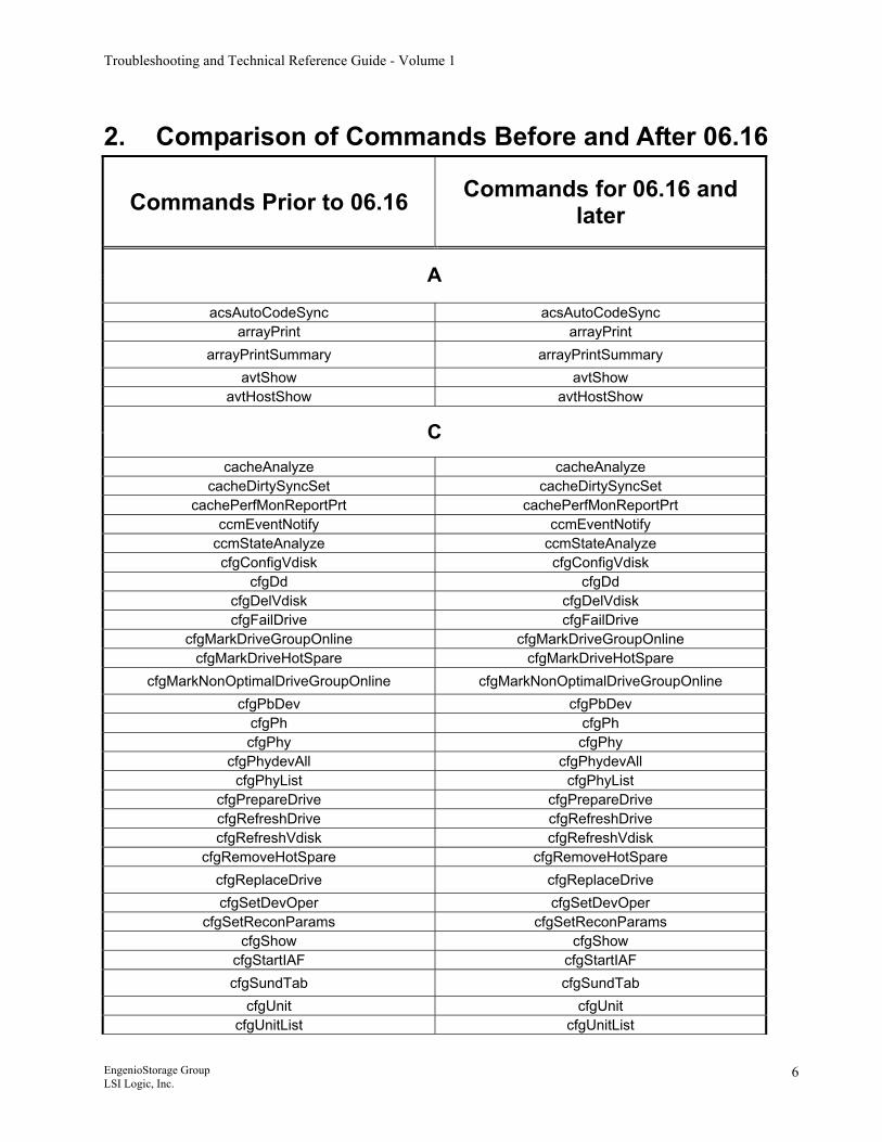
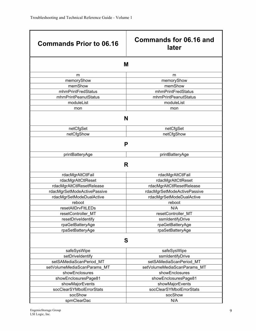
2. Comparison of Commands Before and After 06.16
Commands Prior to 06.16 Commands for 06.16 and later
A
acsAutoCodeSync acsAutoCodeSync arrayPrint arrayPrint
arrayPrintSummary arrayPrintSummary avtShow avtShow
avtHostShow avtHostShow
C cacheAnalyze cacheAnalyze
cacheDirtySyncSet cacheDirtySyncSet cachePerfMonReportPrt cachePerfMonReportPrt
ccmEventNotify ccmEventNotify ccmStateAnalyze ccmStateAnalyze cfgConfigVdisk cfgConfigVdisk
cfgDd cfgDd cfgDelVdisk cfgDelVdisk cfgFailDrive cfgFailDrive
cfgMarkDriveGroupOnline cfgMarkDriveGroupOnline cfgMarkDriveHotSpare cfgMarkDriveHotSpare
cfgMarkNonOptimalDriveGroupOnline cfgMarkNonOptimalDriveGroupOnline cfgPbDev cfgPbDev
cfgPh cfgPh cfgPhy cfgPhy
cfgPhydevAll cfgPhydevAll cfgPhyList cfgPhyList
cfgPrepareDrive cfgPrepareDrive cfgRefreshDrive cfgRefreshDrive cfgRefreshVdisk cfgRefreshVdisk
cfgRemoveHotSpare cfgRemoveHotSpare cfgReplaceDrive cfgReplaceDrive cfgSetDevOper cfgSetDevOper
cfgSetReconParams cfgSetReconParams cfgShow cfgShow
cfgStartIAF cfgStartIAF cfgSundTab cfgSundTab
cfgUnit cfgUnit cfgUnitList cfgUnitList
EngenioStorage Group LSI Logic, Inc.
6
Troubleshooting and Technical Reference Guide - Volume 1
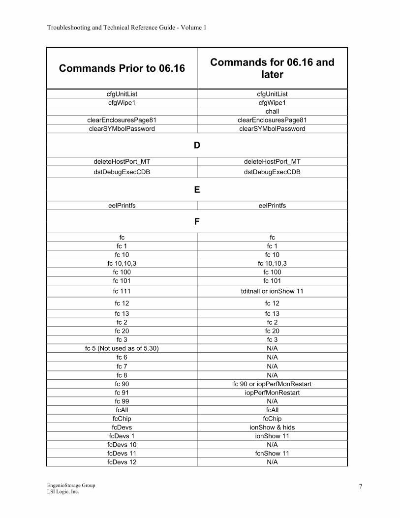
Commands Prior to 06.16 Commands for 06.16 and later
cfgUnitList cfgUnitList cfgWipe1 cfgWipe1
chall clearEnclosuresPage81 clearEnclosuresPage81 clearSYMbolPassword clearSYMbolPassword
D deleteHostPort_MT deleteHostPort_MT dstDebugExecCDB dstDebugExecCDB
E eelPrintfs eelPrintfs
F fc fc
fc 1 fc 1 fc 10 fc 10
fc 10,10,3 fc 10,10,3 fc 100 fc 100 fc 101 fc 101 fc 111 tditnall or ionShow 11
fc 12 fc 12 fc 13 fc 13 fc 2 fc 2 fc 20 fc 20 fc 3 fc 3
fc 5 (Not used as of 5.30) N/A fc 6 N/A fc 7 N/A fc 8 N/A fc 90 fc 90 or iopPerfMonRestart fc 91 iopPerfMonRestart fc 99 N/A fcAll fcAll
fcChip fcChip fcDevs ionShow & hids
fcDevs 1 ionShow 11 fcDevs 10 N/A fcDevs 11 fcnShow 11 fcDevs 12 N/A
EngenioStorage Group LSI Logic, Inc.
7
Troubleshooting and Technical Reference Guide - Volume 1
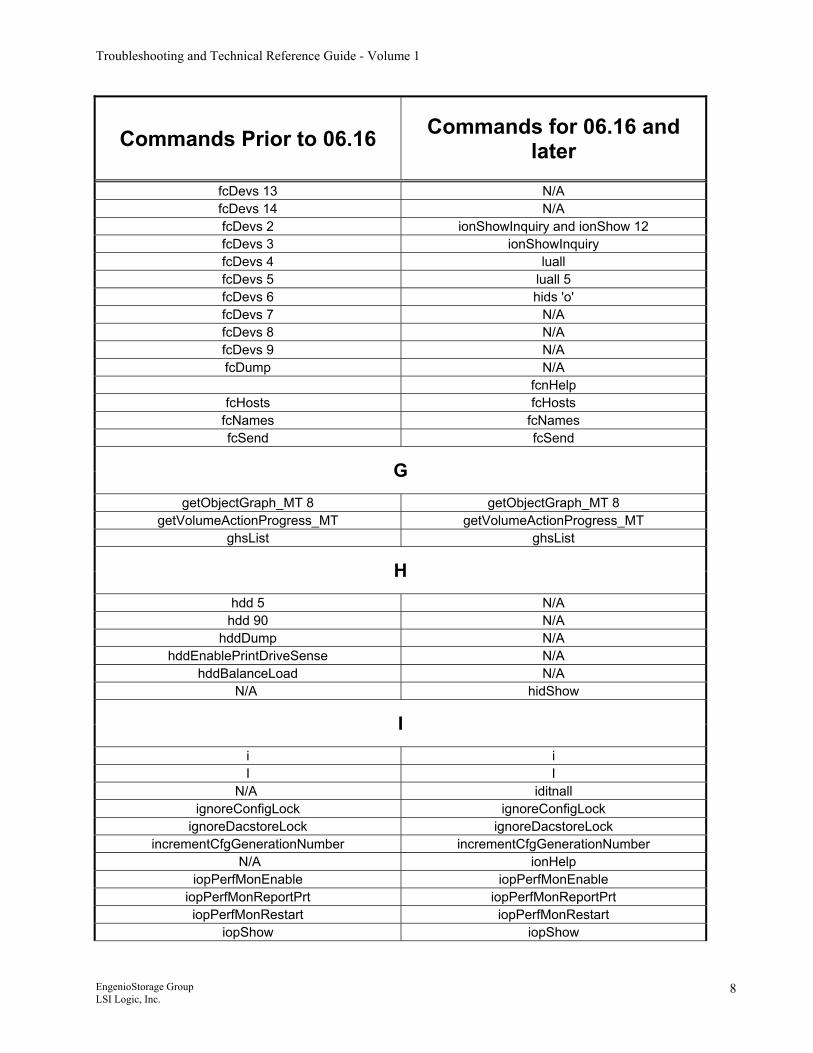
Commands Prior to 06.16 Commands for 06.16 and later
fcDevs 13 N/A fcDevs 14 N/A fcDevs 2 ionShowInquiry and ionShow 12 fcDevs 3 ionShowInquiry fcDevs 4 luall fcDevs 5 luall 5 fcDevs 6 hids 'o' fcDevs 7 N/A fcDevs 8 N/A fcDevs 9 N/A fcDump N/A
fcnHelp fcHosts fcHosts
fcNames fcNames fcSend fcSend
G getObjectGraph_MT 8 getObjectGraph_MT 8
getVolumeActionProgress_MT getVolumeActionProgress_MT ghsList ghsList
H hdd 5 N/A
hdd 90 N/A hddDump N/A
hddEnablePrintDriveSense N/A hddBalanceLoad N/A
N/A hidShow
I i i I I
N/A iditnall ignoreConfigLock ignoreConfigLock
ignoreDacstoreLock ignoreDacstoreLock incrementCfgGenerationNumber incrementCfgGenerationNumber
N/A ionHelp iopPerfMonEnable iopPerfMonEnable
iopPerfMonReportPrt iopPerfMonReportPrt iopPerfMonRestart iopPerfMonRestart
iopShow iopShow
EngenioStorage Group LSI Logic, Inc.
8
Troubleshooting and Technical Reference Guide - Volume 1
Commands Prior to 06.16 Commands for 06.16 and later
M m m
memoryShow memoryShow memShow memShow
mhmPrintFredStatus mhmPrintFredStatus mhmPrintPeanutStatus mhmPrintPeanutStatus
moduleList moduleList mon mon
N netCfgSet netCfgSet
netCfgShow netCfgShow
P printBatteryAge printBatteryAge
R rdacMgrAltCtlFail rdacMgrAltCtlFail
rdacMgrAltCtlReset rdacMgrAltCtlReset rdacMgrAltCtlResetRelease rdacMgrAltCtlResetRelease
rdacMgrSetModeActivePassive rdacMgrSetModeActivePassive rdacMgrSetModeDualActive rdacMgrSetModeDualActive
reboot reboot resetAllDrvFltLEDs N/A resetController_MT resetController_MT resetDriveIdentify ssmIdentifyDrive rpaGetBatteryAge rpaGetBatteryAge rpaSetBatteryAge rpaSetBatteryAge
S safeSysWipe safeSysWipe
setDriveIdentify ssmIdentifyDrive setSAMediaScanPeriod_MT setSAMediaScanPeriod_MT
setVolumeMediaScanParams_MT setVolumeMediaScanParams_MT showEnclosures showEnclosures
showEnclosuresPage81 showEnclosuresPage81 showMajorEvents showMajorEvents
socClearSYMbolErrorStats socClearSYMbolErrorStats socShow socShow
spmClearDac N/A
EngenioStorage Group LSI Logic, Inc.
9
Troubleshooting and Technical Reference Guide - Volume 1
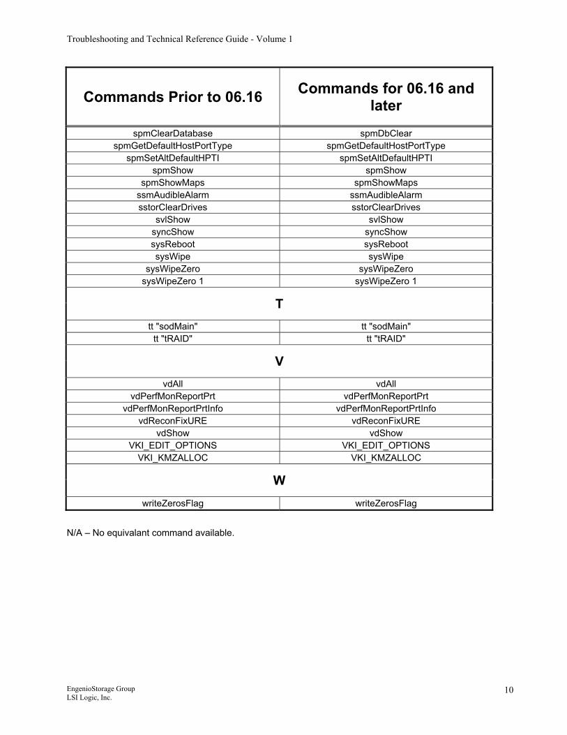
Commands Prior to 06.16 Commands for 06.16 and later
spmClearDatabase spmDbClear spmGetDefaultHostPortType spmGetDefaultHostPortType
spmSetAltDefaultHPTI spmSetAltDefaultHPTI spmShow spmShow
spmShowMaps spmShowMaps ssmAudibleAlarm ssmAudibleAlarm sstorClearDrives sstorClearDrives
svlShow svlShow syncShow syncShow sysReboot sysReboot sysWipe sysWipe
sysWipeZero sysWipeZero sysWipeZero 1 sysWipeZero 1
T tt "sodMain" tt "sodMain"
tt "tRAID" tt "tRAID"
V vdAll vdAll
vdPerfMonReportPrt vdPerfMonReportPrt vdPerfMonReportPrtInfo vdPerfMonReportPrtInfo
vdReconFixURE vdReconFixURE vdShow vdShow
VKI_EDIT_OPTIONS VKI_EDIT_OPTIONS VKI_KMZALLOC VKI_KMZALLOC
W writeZerosFlag writeZerosFlag
N/A – No equivalant command available.
EngenioStorage Group LSI Logic, Inc.
10
Troubleshooting and Technical Reference Guide - Volume 1
3. Shell Commands - Usage and Explanation
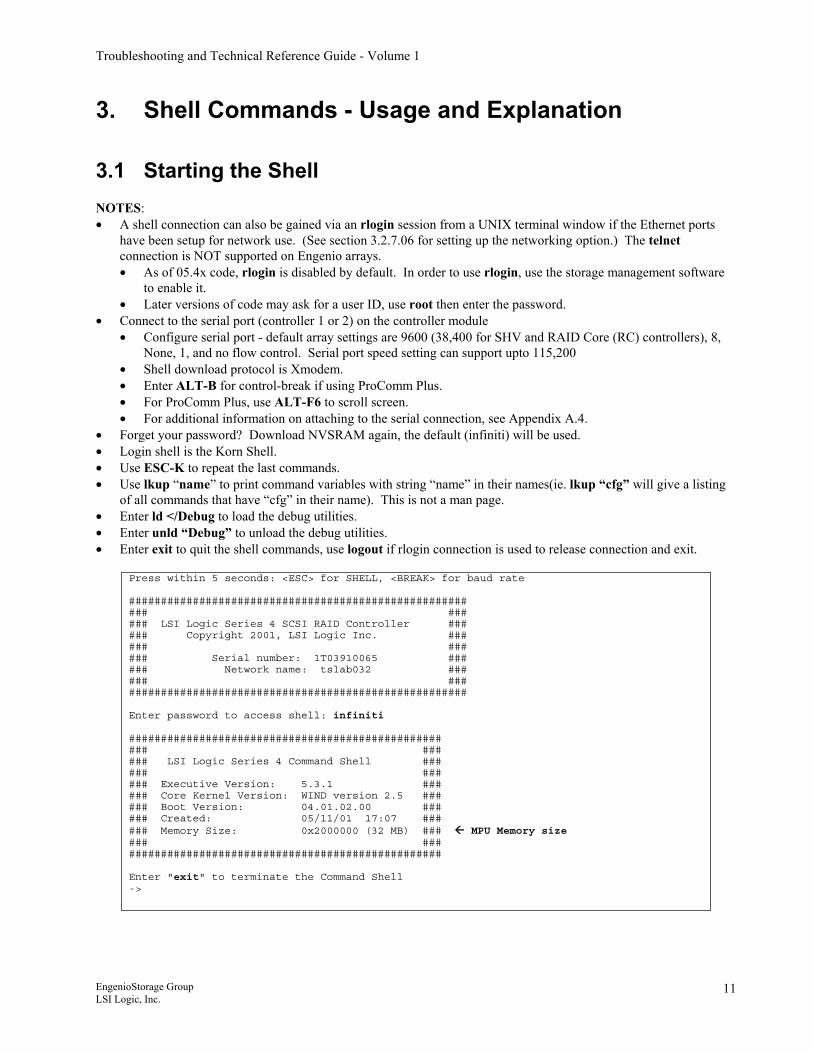
3.1 Starting the Shell NOTES: • A shell connection can also be gained via an rlogin session from a UNIX terminal window if the Ethernet ports
have been setup for network use. (See section 3.2.7.06 for setting up the networking option.) The telnet connection is NOT supported on Engenio arrays. • As of 05.4x code, rlogin is disabled by default. In order to use rlogin, use the storage management software
to enable it. • Later versions of code may ask for a user ID, use root then enter the password.
• Connect to the serial port (controller 1 or 2) on the controller module • Configure serial port - default array settings are 9600 (38,400 for SHV and RAID Core (RC) controllers), 8,
None, 1, and no flow control. Serial port speed setting can support upto 115,200 • Shell download protocol is Xmodem. • Enter ALT-B for control-break if using ProComm Plus. • For ProComm Plus, use ALT-F6 to scroll screen. • For additional information on attaching to the serial connection, see Appendix A.4.
• Forget your password? Download NVSRAM again, the default (infiniti) will be used. • Login shell is the Korn Shell. • Use ESC-K to repeat the last commands. • Use lkup “name” to print command variables with string “name” in their names(ie. lkup “cfg” will give a listing
of all commands that have “cfg” in their name). This is not a man page. • Enter ld </Debug to load the debug utilities. • Enter unld “Debug” to unload the debug utilities. • Enter exit to quit the shell commands, use logout if rlogin connection is used to release connection and exit.
Press within 5 seconds: <ESC> for SHELL, <BREAK> for baud rate ##################################################### ### ### ### LSI Logic Series 4 SCSI RAID Controller ### ### Copyright 2001, LSI Logic Inc. ### ### ### ### Serial number: 1T03910065 ### ### Network name: tslab032 ### ### ### ##################################################### Enter password to access shell: infiniti ################################################# ### ### ### LSI Logic Series 4 Command Shell ### ### ### ### Executive Version: 5.3.1 ### ### Core Kernel Version: WIND version 2.5 ### ### Boot Version: 04.01.02.00 ### ### Created: 05/11/01 17:07 ### ### Memory Size: 0x2000000 (32 MB) ### MPU Memory size ### ### ################################################# Enter "exit" to terminate the Command Shell ->
EngenioStorage Group LSI Logic, Inc.
11
Troubleshooting and Technical Reference Guide - Volume 1
3.2 Shell Commands
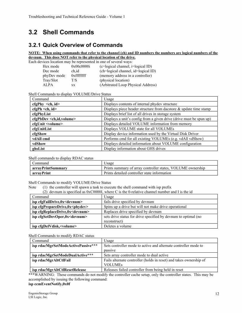
3.2.1 Quick Overview of Commands NOTE: When using commands that refer to the channel (ch) and ID numbers the numbers are logical numbers of the devnum. This does NOT refer to the physical location of the drive. Each devices location may be represented in one of several ways:
Hex mode 0x00c0000i (c=logical channel, i=logical ID) Dec mode ch,id (ch=logical channel, id=logical ID) phyDev mode 0xffffffff (memory address in a controller) Tray/Slot T/S (physical location) ALPA xx (Arbitrated Loop Physical Address)
Shell Commands to display VOLUME/Drive Status Command Usage cfgPhy <ch, id> Displays contents of internal phydev structure cfgPh <ch, id> Displays piece header structure from dacstore & update time stamp cfgPhyList Displays brief list of all drives in storage system cfgPbDev <ch,id,volume> Displays a unit’s config from a given drive (drive must be spun up) cfgUnit <volume> Displays detailed VOLUME information from memory cfgUnitList Displays VOLUME state for all VOLUMEs cfgShow Display device information used by the Virtual Disk Driver vdAll cmd Performs cmd for all existing VOLUMEs (e.g. vdAll vdShow) vdShow Displays detailed information about VOLUME configuration ghsList Display information about GHS drives
Shell commands to display RDAC status
Command Usage arrayPrintSummary Prints summary of array controller states, VOLUME ownership arrayPrint Prints detailed controller state information
Shell Commands to modify VOLUME/Drive Status Note (1) the controller will spawn a task to execute the shell command with isp prefix (2) devnum is specified as 0xC0000I, where C is the 0-relative channel number and I is the id
Command Usage isp cfgFailDrive,0x<devnum> fails drive specified by devnum isp cfgPrepareDrive,0x<phydev> Spins up a drive but will not make drive operational isp cfgReplaceDrive,0x<devnum> Replaces drive specified by devnum isp cfgSetDevOper,0x<devnum> sets drive status for drive specified by devnum to optimal (no
reconstruct) isp cfgDelVdisk,<volume> Deletes a volume
Shell Commands to modify RDAC status
Command Usage isp rdacMgrSetModeActivePassive*** Sets controller mode to active and alternate controller mode to
passive isp rdacMgrSetModeDualActive*** Sets array controller mode to dual active isp rdacMgrAltCtlFail Fails alternate controller (holds in reset) and takes ownership of
VOLUMEs isp rdacMgrAltCtlResetRelease Releases failed controller from being held in reset
***WARNING: These commands do not modify the controller cache setup, only the controller states. This may be accomplished by issuing the following command: isp ccmEventNotify,0x0f
EngenioStorage Group LSI Logic, Inc.
12
Troubleshooting and Technical Reference Guide - Volume 1
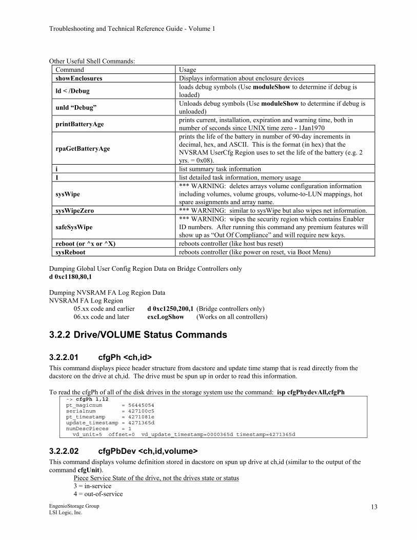
Other Useful Shell Commands:
Command Usage showEnclosures Displays information about enclosure devices
ld < /Debug loads debug symbols (Use moduleShow to determine if debug is loaded)
unld “Debug” Unloads debug symbols (Use moduleShow to determine if debug is unloaded)
printBatteryAge prints current, installation, expiration and warning time, both in number of seconds since UNIX time zero - 1Jan1970
rpaGetBatteryAge
prints the life of the battery in number of 90-day increments in decimal, hex, and ASCII. This is the format (in hex) that the NVSRAM UserCfg Region uses to set the life of the battery (e.g. 2 yrs. = 0x08).
i list summary task information I list detailed task information, memory usage
sysWipe *** WARNING: deletes arrays volume configuration information including volumes, volume groups, volume-to-LUN mappings, hot spare assignments and array name.
sysWipeZero *** WARNING: similar to sysWipe but also wipes net information.
safeSysWipe *** WARNING: wipes the security region which contains Enabler ID numbers. After running this command any premium features will show up as “Out Of Compliance” and will require new keys.
reboot (or ^x or ^X) reboots controller (like host bus reset) sysReboot reboots controller (like power on reset, via Boot Menu)
Dumping Global User Config Region Data on Bridge Controllers only d 0xc1180,80,1 Dumping NVSRAM FA Log Region Data NVSRAM FA Log Region
05.xx code and earlier d 0xc1250,200,1 (Bridge controllers only) 06.xx code and later excLogShow (Works on all controllers)
3.2.2 Drive/VOLUME Status Commands
3.2.2.01 cfgPh <ch,id> This command displays piece header structure from dacstore and update time stamp that is read directly from the dacstore on the drive at ch,id. The drive must be spun up in order to read this information. To read the cfgPh of all of the disk drives in the storage system use the command: isp cfgPhydevAll,cfgPh
-> cfgPh 1,12 pt_magicnum = 56445054 serialnum = 427100c5 pt_timestamp = 4271081e update_timestamp = 4271365d numDescPieces = 1 vd_unit=5 offset=0 vd_update_timestamp=0000365d timestamp=4271365d
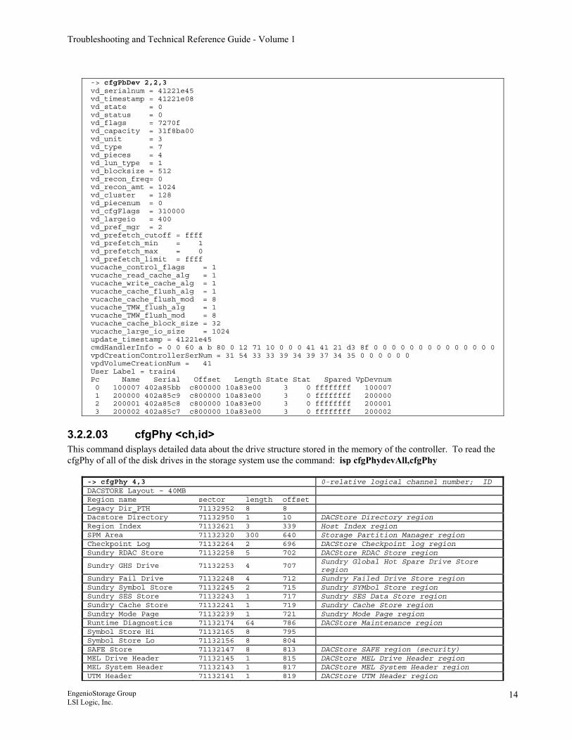
3.2.2.02 cfgPbDev <ch,id,volume> This command displays volume definition stored in dacstore on spun up drive at ch,id (similar to the output of the command cfgUnit).
Piece Service State of the drive, not the drives state or status 3 = in-service 4 = out-of-service
EngenioStorage Group LSI Logic, Inc.
13
Troubleshooting and Technical Reference Guide - Volume 1
-> cfgPbDev 2,2,3 vd_serialnum = 41221e45 vd_timestamp = 41221e08 vd_state = 0 vd_status = 0 vd_flags = 7270f vd_capacity = 31f8ba00 vd_unit = 3 vd_type = 7 vd_pieces = 4 vd_lun_type = 1 vd_blocksize = 512 vd_recon_freq= 0 vd_recon_amt = 1024 vd_cluster = 128 vd_piecenum = 0 vd_cfgFlags = 310000 vd_largeio = 400 vd_pref_mgr = 2 vd_prefetch_cutoff = ffff vd_prefetch_min = 1 vd_prefetch_max = 0 vd_prefetch_limit = ffff vucache_control_flags = 1 vucache_read_cache_alg = 1 vucache_write_cache_alg = 1 vucache_cache_flush_alg = 1 vucache_cache_flush_mod = 8 vucache_TMW_flush_alg = 1 vucache_TMW_flush_mod = 8 vucache_cache_block_size = 32 vucache_large_io_size = 1024 update_timestamp = 41221e45 cmdHandlerInfo = 0 0 60 a b 80 0 12 71 10 0 0 0 41 41 21 d3 8f 0 0 0 0 0 0 0 0 0 0 0 0 0 0 vpdCreationControllerSerNum = 31 54 33 33 39 34 39 37 34 35 0 0 0 0 0 0 vpdVolumeCreationNum = 41 User Label = train4 Pc Name Serial Offset Length State Stat Spared VpDevnum 0 100007 402a85bb c800000 10a83e00 3 0 ffffffff 100007 1 200000 402a85c9 c800000 10a83e00 3 0 ffffffff 200000 2 200001 402a85c8 c800000 10a83e00 3 0 ffffffff 200001 3 200002 402a85c7 c800000 10a83e00 3 0 ffffffff 200002
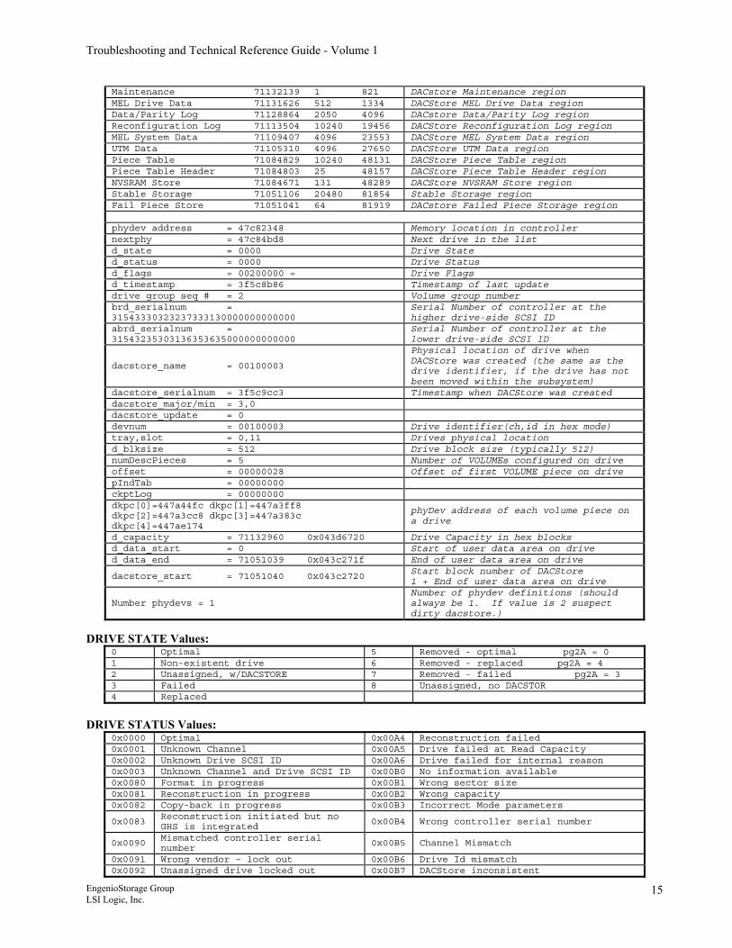
3.2.2.03 cfgPhy <ch,id> This command displays detailed data about the drive structure stored in the memory of the controller. To read the cfgPhy of all of the disk drives in the storage system use the command: isp cfgPhydevAll,cfgPhy
-> cfgPhy 4,3 0-relative logical channel number; ID DACSTORE Layout – 40MB Region name sector length offset Legacy Dir_PTH 71132952 8 8 Dacstore Directory 71132950 1 10 DACStore Directory region Region Index 71132621 3 339 Host Index region SPM Area 71132320 300 640 Storage Partition Manager region Checkpoint Log 71132264 2 696 DACStore Checkpoint log region Sundry RDAC Store 71132258 5 702 DACStore RDAC Store region
Sundry GHS Drive 71132253 4 707 Sundry Global Hot Spare Drive Store region
Sundry Fail Drive 71132248 4 712 Sundry Failed Drive Store region Sundry Symbol Store 71132245 2 715 Sundry SYMbol Store region Sundry SES Store 71132243 1 717 Sundry SES Data Store region Sundry Cache Store 71132241 1 719 Sundry Cache Store region Sundry Mode Page 71132239 1 721 Sundry Mode Page region Runtime Diagnostics 71132174 64 786 DACStore Maintenance region Symbol Store Hi 71132165 8 795 Symbol Store Lo 71132156 8 804 SAFE Store 71132147 8 813 DACStore SAFE region (security) MEL Drive Header 71132145 1 815 DACStore MEL Drive Header region MEL System Header 71132143 1 817 DACStore MEL System Header region UTM Header 71132141 1 819 DACStore UTM Header region
EngenioStorage Group LSI Logic, Inc.
14
Troubleshooting and Technical Reference Guide - Volume 1
Maintenance 71132139 1 821 DACstore Maintenance region MEL Drive Data 71131626 512 1334 DACStore MEL Drive Data region Data/Parity Log 71128864 2050 4096 DACstore Data/Parity Log region Reconfiguration Log 71113504 10240 19456 DACStore Reconfiguration Log region MEL System Data 71109407 4096 23553 DACStore MEL System Data region UTM Data 71105310 4096 27650 DACStore UTM Data region Piece Table 71084829 10240 48131 DACStore Piece Table region Piece Table Header 71084803 25 48157 DACStore Piece Table Header region NVSRAM Store 71084671 131 48289 DACStore NVSRAM Store region Stable Storage 71051106 20480 81854 Stable Storage region Fail Piece Store 71051041 64 81919 DACstore Failed Piece Storage region phydev address = 47c82348 Memory location in controller nextphy = 47c84bd8 Next drive in the list d_state = 0000 Drive State d_status = 0000 Drive Status d_flags = 00200000 = Drive Flags d_timestamp = 3f5c8b86 Timestamp of last update drive group seq # = 2 Volume group number brd_serialnum = 31543330323237333130000000000000
Serial Number of controller at the higher drive-side SCSI ID
abrd_serialnum = 31543235303136353635000000000000
Serial Number of controller at the lower drive-side SCSI ID
dacstore_name = 00100003
Physical location of drive when DACStore was created (the same as the drive identifier, if the drive has not been moved within the subsystem)
dacstore_serialnum = 3f5c9cc3 Timestamp when DACStore was created dacstore_major/min = 3,0 dacstore_update = 0 devnum = 00100003 Drive identifier(ch,id in hex mode) tray,slot = 0,11 Drives physical location d_blksize = 512 Drive block size (typically 512) numDescPieces = 5 Number of VOLUMEs configured on drive offset = 00000028 Offset of first VOLUME piece on drive pIndTab = 00000000 ckptLog = 00000000 dkpc[0]=447a44fc dkpc[1]=447a3ff8 dkpc[2]=447a3cc8 dkpc[3]=447a383c dkpc[4]=447ae174
phyDev address of each volume piece on a drive
d_capacity = 71132960 0x043d6720 Drive Capacity in hex blocks d_data_start = 0 Start of user data area on drive d_data_end = 71051039 0x043c271f End of user data area on drive
dacstore_start = 71051040 0x043c2720 Start block number of DACStore 1 + End of user data area on drive
Number phydevs = 1 Number of phydev definitions (should always be 1. If value is 2 suspect dirty dacstore.)
DRIVE STATE Values:
0 Optimal 5 Removed - optimal pg2A = 0 1 Non-existent drive 6 Removed - replaced pg2A = 4 2 Unassigned, w/DACSTORE 7 Removed - failed pg2A = 3 3 Failed 8 Unassigned, no DACSTOR 4 Replaced
DRIVE STATUS Values:
0x0000 Optimal 0x00A4 Reconstruction failed 0x0001 Unknown Channel 0x00A5 Drive failed at Read Capacity 0x0002 Unknown Drive SCSI ID 0x00A6 Drive failed for internal reason 0x0003 Unknown Channel and Drive SCSI ID 0x00B0 No information available 0x0080 Format in progress 0x00B1 Wrong sector size 0x0081 Reconstruction in progress 0x00B2 Wrong capacity 0x0082 Copy-back in progress 0x00B3 Incorrect Mode parameters
0x0083 Reconstruction initiated but no GHS is integrated
0x00B4 Wrong controller serial number
0x0090 Mismatched controller serial number
0x00B5 Channel Mismatch
0x0091 Wrong vendor – lock out 0x00B6 Drive Id mismatch 0x0092 Unassigned drive locked out 0x00B7 DACStore inconsistent
EngenioStorage Group LSI Logic, Inc.
15
Troubleshooting and Technical Reference Guide - Volume 1
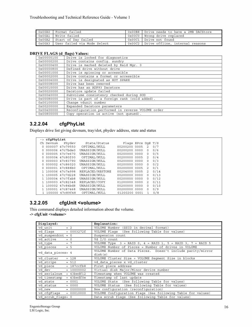
0x00A0 Format failed 0x00B8 Drive needs to have a 2MB DACStore 0x00A1 Write failed 0x00C0 Wrong drive replaced 0x00A2 Start of Day failed 0x00C1 Drive not found 0x00A3 User failed via Mode Select 0x00C2 Drive offline, internal reasons
DRIVE FLAGS (d_flags) Values:
0x00000100 Drive is locked for diagnostics 0x00000200 Drive contains config. sundry� 0x00000400 Drive is marked deleted by Raid Mgr.�0 0x00000800 Defined drive without drive 0x00001000 Drive is spinning or accessible 0x00002000 Drive contains a format or accessible 0x00004000 Drive is designated as HOT SPARE 0x00008000 Drive has been removed 0x00010000 Drive has an ADP93 Dacstore 0x00020000 Dacstore update failed 0x00040000 Subvolume consistency checked during SOD 0x00080000 Drive is part of a foreign rank (cold added). 0x00100000 Change vdunit number 0x00200000 Expanded Dacstore parameters 0x00400000 Reconfiguration performed in reverse VOLUME order 0x00800000 Copy operation is active (not queued).
3.2.2.04 cfgPhyList Displays drive list giving devnum, tray/slot, phydev address, state and status
-> cfgPhyList Ch Devnum Phydev State/Status Flags #Pcs Dg# T/S 0 000007 47c79550 OPTIMAL/NULL 00200200 0005 2 0/7 0 000006 47c7bde0 UNASSIGN/NULL 00200200 0000 0 0/6 0 000005 47c7e670 UNASSIGN/NULL 00200000 0000 0 0/5 0 000004 47c80f00 OPTIMAL/NULL 00200000 0005 2 0/4 0 000003 47c83790 UNASSIGN/NULL 00200000 0000 0 0/3 0 000002 47c86020 UNASSIGN/NULL 00200000 0000 0 0/2 0 000001 47c888b0 OPTIMAL/NULL 00200000 0005 2 0/1 1 100006 47c7a998 REPLACED/RESTORE 00204000 0005 2 0/14 1 100005 47c7d228 UNASSIGN/NULL 00200000 0000 0 0/13 1 100004 47c7fab8 UNASSIGN/NULL 00200000 0000 0 0/12 1 100003 47c82348 REPLACED/COPY 01200000 0000 2 0/11 1 100002 47c84bd8 UNASSIGN/NULL 00200000 0000 0 0/10 1 100001 47c87468 UNASSIGN/NULL 00200000 0000 0 0/9 1 100000 47c89f48 OPTIMAL/NULL 01200200 0001 1 0/8
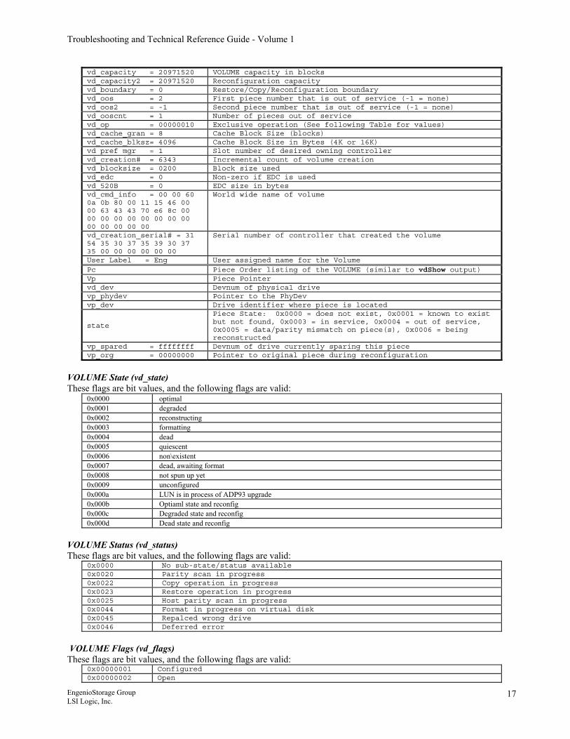
3.2.2.05 cfgUnit <volume> This command displays detailed information about the volume. -> cfgUnit <volume>
Displayed: Explanation: vd_unit = 2 VOLUME Number (SSID in decimal format) vd_flags = 0003272f VOLUME Flags (See following Table for values) vd_suspendcnt = 0 Suspension count vd_active = 0 Vd I/O count vd_type = 7 VOLUME Type 3 = RAID 0, 4 = RAID 1, 5 = RAID 3, 7 = RAID 5 vd_pieces = 5 VOLUME Number of Pieces = Number of drives in VOLUME
vd_data_pieces= 4 VOLUME Number of Data Pieces. Doesn’t include parity/mirror disk(s)
vd_cluster = 128 VOLUME Cluster Size = VOLUME Segment Size in blocks vd_stripe = 512 vd_data_pieces x vd_cluster vd_piece = 187ccfb8 First piece address vd_dev = 10000002 Virtual disk Major/Minor device number vd_serialnum = 43bedf12 Timestamp when VOLUME was created vd_timestamp = 43bedf0e Timestamp of last update vd_state = 0001 VOLUME State (See following Table for values) vd_status = 0000 VOLUME Status (See following Table for values) vd_new = 00000000 New configuration (reconfiguration) vd_cfgFlags = 00010000 VOLUME Configuration Flags (See following Table for values) vd_scrub_flags= 0 Data scrub flags (See following Table for values)
EngenioStorage Group LSI Logic, Inc.
16
Troubleshooting and Technical Reference Guide - Volume 1
vd_capacity = 20971520 VOLUME capacity in blocks vd_capacity2 = 20971520 Reconfiguration capacity vd_boundary = 0 Restore/Copy/Reconfiguration boundary vd_oos = 2 First piece number that is out of service (-1 = none) vd_oos2 = -1 Second piece number that is out of service (-1 = none) vd_ooscnt = 1 Number of pieces out of service vd_op = 00000010 Exclusive operation (See following Table for values) vd_cache_gran = 8 Cache Block Size (blocks) vd_cache_blksz= 4096 Cache Block Size in Bytes (4K or 16K) vd pref mgr = 1 Slot number of desired owning controller vd_creation# = 6343 Incremental count of volume creation vd_blocksize = 0200 Block size used vd_edc = 0 Non-zero if EDC is used vd_520B = 0 EDC size in bytes vd_cmd_info = 00 00 60 0a 0b 80 00 11 15 46 00 00 63 43 43 70 e6 8c 00 00 00 00 00 00 00 00 00 00 00 00 00 00
World wide name of volume
vd_creation_serial# = 31 54 35 30 37 35 39 30 37 35 00 00 00 00 00 00
Serial number of controller that created the volume
User Label = Eng User assigned name for the Volume Pc Piece Order listing of the VOLUME (similar to vdShow output) Vp Piece Pointer vd_dev Devnum of physical drive vp_phydev Pointer to the PhyDev vp_dev Drive identifier where piece is located
state
Piece State: 0x0000 = does not exist, 0x0001 = known to exist but not found, 0x0003 = in service, 0x0004 = out of service, 0x0005 = data/parity mismatch on piece(s), 0x0006 = being reconstructed
vp_spared = ffffffff Devnum of drive currently sparing this piece vp_org = 00000000 Pointer to original piece during reconfiguration
VOLUME State (vd_state) These flags are bit values, and the following flags are valid:
0x0000 optimal 0x0001 degraded 0x0002 reconstructing 0x0003 formatting 0x0004 dead 0x0005 quiescent 0x0006 non\existent 0x0007 dead, awaiting format 0x0008 not spun up yet 0x0009 unconfigured 0x000a LUN is in process of ADP93 upgrade 0x000b Optiaml state and reconfig 0x000c Degraded state and reconfig 0x000d Dead state and reconfig
VOLUME Status (vd_status) These flags are bit values, and the following flags are valid:
0x0000 No sub-state/status available 0x0020 Parity scan in progress 0x0022 Copy operation in progress 0x0023 Restore operation in progress 0x0025 Host parity scan in progress 0x0044 Format in progress on virtual disk 0x0045 Repalced wrong drive 0x0046 Deferred error
VOLUME Flags (vd_flags) These flags are bit values, and the following flags are valid:
0x00000001 Configured 0x00000002 Open
EngenioStorage Group LSI Logic, Inc.
17
Troubleshooting and Technical Reference Guide - Volume 1
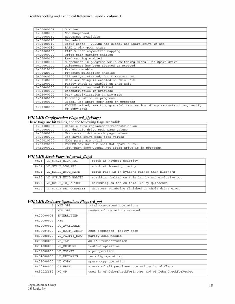
0x00000004 On-Line 0x00000008 Not Suspended 0x00000010 Resources available 0x00000020 Degraded 0x00000040 Spare piece - VOLUME has Global Hot Spare drive in use 0x00000080 RAID 1 ping-pong state 0x00000100 RAID 5 left asymmetric mapping 0x00000200 Write-back caching enabled 0x00000400 Read caching enabled 0x00000800 Suspension in progress while switching Global Hot Spare drive 0x00001000 Quiescence has been aborted or stopped 0x00010000 Prefetch enabled 0x00020000 Prefetch multiplier enabled 0x00040000 IAF not yet started, don't restart yet 0x00100000 Data scrubbing is enabled on this unit 0x00200000 Parity check is enabled on this unit 0x00400000 Reconstruction read failed 0x01000000 Reconstruction in progress 0x02000000 Data initialization in progress 0x04000000 Reconfiguration in progress 0x08000000 Global Hot Spare copy-back in progress
0x90000000 VOLUME halted; awaiting graceful termination of any reconstruction, verify, or copy-back
VOLUME Configuration Flags (vd_cfgFlags) These flags are bit values, and the following flags are valid:
0x00000002 Disable auto replacement/reconstruction 0x00000000 Use default drive mode page values 0x00000100 Use current drive mode page values 0x00000200 Use saved drive mode page values 0x00010000 Mode pages are valid 0x00020000 VOLUME may use a Global Hot Spare Drive 0x80000000 Copy-back from Global Hot Spare drive is in progress
VOLUME Scrub Flags (vd_scrub_flags)
0x01 VD_SCRUB_HIGH_PRI scrub at highest priority
0x02 VD_SCRUB_LOW_PRI scrub at lowest priority
0x04 VD_SCRUB_BYTE_RATE scrub rate is in bytes/s rather than blocks/s
0x10 VD_SCRUB_EXCL_HALTED scrubbing halted on this lun by and exclusive op.
0x20 VD_SCRUB_IO_HALTED scrubbing halted on this lun by quiesence
0x40 VD_SCRUB_DAC_COMPLETE dacstore scrubbing finished on whole drive group
VOLUME Exclusive Operations Flags (vd_op) 4 MAX_OPS total concurrent operations
7 NUM_OPS number of operations managed
0x00000001 INTERRUPTED
0x00000002 NEW
0x00000010 DG_AVAILABLE
0x00004000 VD_HOST_PARSCN host requested parity scan
0x00008000 VD_PARITY_SCAN parity scan needed
0x00800000 VD_IAF an IAF reconstruction
0x01000000 VD_RESTORE restore operation
0x02000000 VD_FORMAT wipe operation
0x04000000 VD_RECONFIG reconfig operation
0x08000000 VD_COPY spare copy operation
0x0f80c000 OP_MASK a mask of all pertinent operations in vd_flags
0xffffffff NO_OP used in cfgDebugCheckForIntOps and cfgDebugCheckForNewOps
EngenioStorage Group LSI Logic, Inc.
18
Troubleshooting and Technical Reference Guide - Volume 1
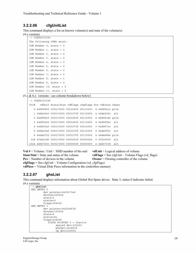
3.2.2.06 cfgUnitList This command displays a list on known volume(s) and state of the volume(s) (4.x version)
-> cfgUnitList
The following LUNs exist:
LUN Number 0, state = 0
LUN Number 1, state = 0
LUN Number 2, state = 0
LUN Number 3, state = 0
LUN Number 4, state = 0
LUN Number 5, state = 2
LUN Number 6, state = 0
LUN Number 7, state = 0
LUN Number 8, state = 1
LUN Number 9, state = 0
LUN Number 10, state = 0
LUN Number 11, state = 0
(5.x & 6.x versions - see column breakdown below) -> cfgUnitList
Vol# vdUnit State/Stat vdFlags cfgFlags Pcs vdPiece Owner
0 44d9f860 0000/0000 0023260f 00110000 4 44d9fa1c prim
1 44da00e0 0000/0000 0023270f 00110000 4 44da029c alt
2 44d9fb20 0000/0000 0053260f 00110000 4 44d9fcdc prim
3 44d9fe00 0000/0000 0003260f 00110000 4 44d9ffbc alt
4 44d9f5a0 0000/0000 0003270f 00010000 3 44d9f75c alt
5 44da03a0 0000/0000 0023270f 00110000 4 44da055c alt
6 44da4720 0000/0000 0053270f 00110000 4 44da48dc prim
128 47eb41d0 0000/0000 0000000f 00000004 0 00000000 alt
1024 44d3720c 0000/0000 0000000f 00000000 2 44d373c8 alt
Vol # = Volume / Unit / SSID number of the unit vdUnit = Logical address of volume State/Stat = State and status of the volume vdFlags = See cfgUnit – Volume Flags (vd_flags) Pcs = Number of devices in the volume Owner = Owning controller of the volume cfgFlags = See cfgUnit – Volume Configuration (vd_cfgFlags) vdPiece = Virtual Disk Piece information in the controllers memory
3.2.2.07 ghsList This command displays information about Global Hot Spare drives. State 3, status 0 indicates failed. (4.x version)
-> ghslist GHS ENTRY 0 dev pointer=0x35c73a0 devnum=300004 state=2 status=0 flags=204000 GHS ENTRY 1 dev pointer=0x35c8f18 devnum=100004 state=4 status=81 flags=204000 PIECE POINTER 0 = 35ac1c4 spared dev=100003 phydev=35c8f18 vp_dev=100004
EngenioStorage Group LSI Logic, Inc.
19
Troubleshooting and Technical Reference Guide - Volume 1
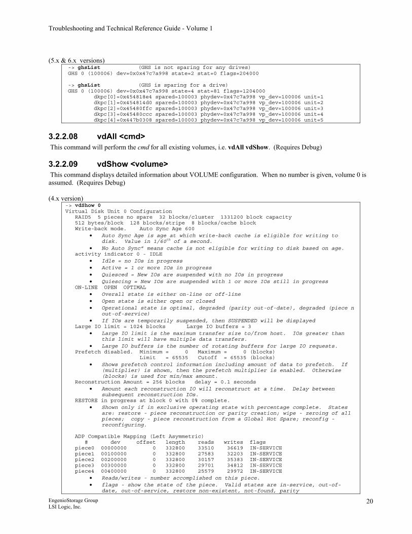
(5.x & 6.x versions)
-> ghsList (GHS is not sparing for any drives) GHS 0 (100006) dev=0x0x47c7a998 state=2 stat=0 flags=204000 -> ghsList (GHS is sparing for a drive) GHS 0 (100006) dev=0x0x47c7a998 state=4 stat=81 flags=1204000 dkpc[0]=0x454818e4 spared=100003 phydev=0x47c7a998 vp_dev=100006 unit=1 dkpc[1]=0x454814d0 spared=100003 phydev=0x47c7a998 vp_dev=100006 unit=2 dkpc[2]=0x45480ffc spared=100003 phydev=0x47c7a998 vp_dev=100006 unit=3 dkpc[3]=0x45480ccc spared=100003 phydev=0x47c7a998 vp_dev=100006 unit=4 dkpc[4]=0x447b0308 spared=100003 phydev=0x47c7a998 vp_dev=100006 unit=5
3.2.2.08 vdAll <cmd> This command will perform the cmd for all existing volumes, i.e. vdAll vdShow. (Requires Debug)
3.2.2.09 vdShow <volume> This command displays detailed information about VOLUME configuration. When no number is given, volume 0 is assumed. (Requires Debug) (4.x version)
-> vdShow 0 Virtual Disk Unit 0 Configuration RAID5 5 pieces no spare 32 blocks/cluster 1331200 block capacity 512 bytes/block 128 blocks/stripe 8 blocks/cache block Write-back mode. Auto Sync Age 600
• Auto Sync Age is age at which write-back cache is eligible for writing to disk. Value in 1/60th of a second.
• No Auto Sync” means cache is not eligible for writing to disk based on age. activity indicator 0 - IDLE
• Idle = no IOs in progress • Active = 1 or more IOs in progress • Quiesced = New IOs are suspended with no IOs in progress • Quiescing = New IOs are suspended with 1 or more IOs still in progress
ON-LINE OPEN OPTIMAL • Overall state is either on-line or off-line • Open state is either open or closed • Operational state is optimal, degraded (parity out-of-date), degraded (piece n
out-of-service) • If IOs are temporarily suspended, then SUSPENDED will be displayed
Large IO limit = 1024 blocks Large IO buffers = 3 • Large IO limit is the maximum transfer size to/from host. IOs greater than
this limit will have multiple data transfers. • Large IO buffers is the number of rotating buffers for large IO requests.
Prefetch disabled. Minimum = 0 Maximum = 0 (blocks) Limit = 65535 Cutoff = 65535 (blocks)
• Shows prefetch control information including amount of data to prefetch. If (multiplier) is shown, then the prefetch multiplier is enabled. Otherwise (blocks) is used for min/max amount.
Reconstruction Amount = 256 blocks delay = 0.1 seconds • Amount each reconstruction IO will reconstruct at a time. Delay between
subsequent reconstruction IOs. RESTORE in progress at block 0 with 0% complete.
• Shown only if in exclusive operating state with percentage complete. States are: restore - piece reconstruction or parity creation; wipe - zeroing of all pieces; copy - piece reconstruction from a Global Hot Spare; reconfig - reconfiguring.
ADP Compatible Mapping (Left Asymmetric) # dev offset length reads writes flags piece0 00000000 0 332800 33510 36619 IN-SERVICE piece1 00100000 0 332800 27583 32203 IN-SERVICE piece2 00200000 0 332800 30157 35383 IN-SERVICE piece3 00300000 0 332800 29701 34812 IN-SERVICE piece4 00400000 0 332800 25579 29972 IN-SERVICE
• Reads/writes - number accomplished on this piece. • flags - show the state of the piece. Valid states are in-service, out-of-
date, out-of-service, restore non-existent, not-found, parity
EngenioStorage Group LSI Logic, Inc.
20
Troubleshooting and Technical Reference Guide - Volume 1
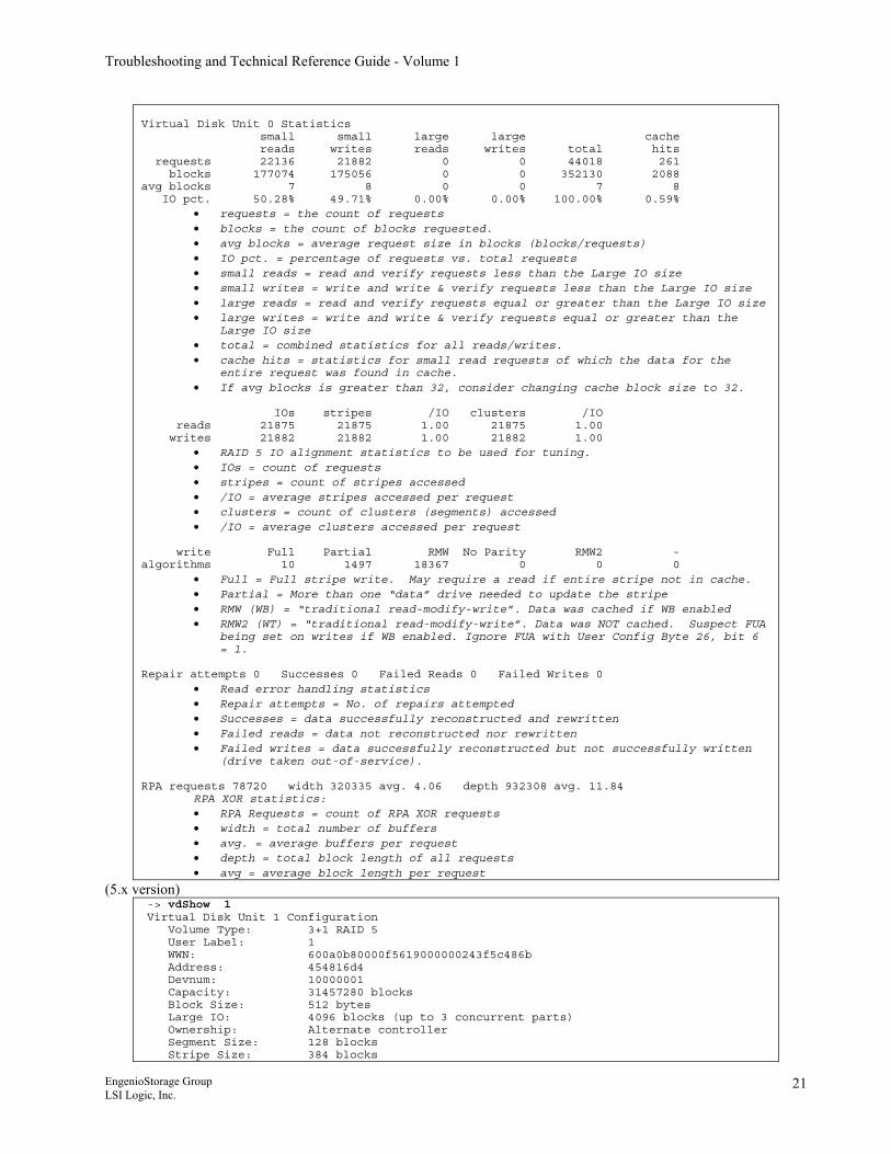
Virtual Disk Unit 0 Statistics small small large large cache reads writes reads writes total hits requests 22136 21882 0 0 44018 261 blocks 177074 175056 0 0 352130 2088 avg blocks 7 8 0 0 7 8 IO pct. 50.28% 49.71% 0.00% 0.00% 100.00% 0.59%
• requests = the count of requests • blocks = the count of blocks requested. • avg blocks = average request size in blocks (blocks/requests) • IO pct. = percentage of requests vs. total requests • small reads = read and verify requests less than the Large IO size • small writes = write and write & verify requests less than the Large IO size • large reads = read and verify requests equal or greater than the Large IO size • large writes = write and write & verify requests equal or greater than the
Large IO size • total = combined statistics for all reads/writes. • cache hits = statistics for small read requests of which the data for the
entire request was found in cache. • If avg blocks is greater than 32, consider changing cache block size to 32.
IOs stripes /IO clusters /IO reads 21875 21875 1.00 21875 1.00 writes 21882 21882 1.00 21882 1.00
• RAID 5 IO alignment statistics to be used for tuning. • IOs = count of requests • stripes = count of stripes accessed • /IO = average stripes accessed per request • clusters = count of clusters (segments) accessed • /IO = average clusters accessed per request
write Full Partial RMW No Parity RMW2 - algorithms 10 1497 18367 0 0 0
• Full = Full stripe write. May require a read if entire stripe not in cache. • Partial = More than one “data” drive needed to update the stripe • RMW (WB) = “traditional read-modify-write”. Data was cached if WB enabled • RMW2 (WT) = “traditional read-modify-write”. Data was NOT cached. Suspect FUA
being set on writes if WB enabled. Ignore FUA with User Config Byte 26, bit 6 = 1.
Repair attempts 0 Successes 0 Failed Reads 0 Failed Writes 0
• Read error handling statistics • Repair attempts = No. of repairs attempted • Successes = data successfully reconstructed and rewritten • Failed reads = data not reconstructed nor rewritten • Failed writes = data successfully reconstructed but not successfully written
(drive taken out-of-service). RPA requests 78720 width 320335 avg. 4.06 depth 932308 avg. 11.84
RPA XOR statistics: • RPA Requests = count of RPA XOR requests • width = total number of buffers • avg. = average buffers per request • depth = total block length of all requests • avg = average block length per request
(5.x version) -> vdShow 1 Virtual Disk Unit 1 Configuration Volume Type: 3+1 RAID 5 User Label: 1 WWN: 600a0b80000f5619000000243f5c486b Address: 454816d4 Devnum: 10000001 Capacity: 31457280 blocks Block Size: 512 bytes Large IO: 4096 blocks (up to 3 concurrent parts) Ownership: Alternate controller Segment Size: 128 blocks Stripe Size: 384 blocks
EngenioStorage Group LSI Logic, Inc.
21
Troubleshooting and Technical Reference Guide - Volume 1
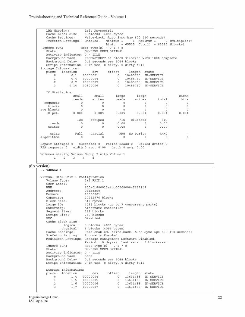
LBA Mapping: Left Asymmetric Cache Block Size: 8 blocks (4096 bytes) Cache Settings: Write-back, Auto Sync Age 600 (10 seconds) Prefetch Settings: Enabled. Minimum = 1 Maximum = 0 (multiplier) Limit = 65535 Cutoff = 65535 (blocks) Ignore FUA: Host type(s) - 0 1 7 8 State: ON-LINE OPEN OPTIMAL Activity indicator: 0 - IDLE Background Task: RECONSTRUCT at block 31457280 with 100% complete Background Delay: 0.1 seconds per 2048 blocks Stripe Information: 0 in-use, 0 dirty, 0 dirty full Storage Information: piece location dev offset length state 0 0,1 00000001 0 10485760 IN-SERVICE 1 0,4 00000004 0 10485760 IN-SERVICE 2 0,7 00000007 0 10485760 IN-SERVICE 3 0,14 00100006 0 10485760 IN-SERVICE IO Statistics: small small large large cache reads writes reads writes total hits requests 0 0 0 0 0 0 blocks 0 0 0 0 0 0 avg blocks 0 0 0 0 0 0 IO pct. 0.00% 0.00% 0.00% 0.00% 0.00% 0.00% IOs stripes /IO clusters /IO reads 0 0 0.00 0 0.00 writes 0 0 0.00 0 0.00 write Full Partial RMW No Parity RMW2 - algorithms 0 0 0 0 0 0 Repair attempts 0 Successes 0 Failed Reads 0 Failed Writes 0 RPA requests 0 width 0 avg. 0.00 depth 0 avg. 0.00 Volumes sharing Volume Group 2 with Volume 1 1 2 3 4 5
(6.x version)
-> vdShow 1 Virtual Disk Unit 1 Configuration Volume Type: 2+2 RAID 1 User Label: 2 WWN: 600a0b800013a4bb00000000426671f9 Address: 031bfa50 Devnum: 10000001 Capacity: 27262976 blocks Block Size: 512 bytes Large IO: 4096 blocks (up to 3 concurrent parts) Ownership: Alternate controller Segment Size: 128 blocks Stripe Size: 256 blocks EDC: Disabled Cache Block Size: logical: 8 blocks (4096 bytes) physical: 8 blocks (4096 bytes) Cache Settings: Read-enabled, Write-back, Auto Sync Age 600 (10 seconds) Prefetch Setting: Automatic Enabled. MediaScan Settings: Storage Management Software Disabled. Period = 0 day(s). Last rate = 0 blocks/sec. Ignore FUA: Host type(s) - 0 1 7 8 State: ON-LINE OPEN OPTIMAL Activity indicator: 0 - IDLE Background Task: none Background Delay: 0.1 seconds per 2048 blocks Stripe Information: 0 in-use, 0 dirty, 0 dirty full Storage Information: piece location dev offset length state 0 1,4 00000004 0 13631488 IN-SERVICE 1 1,5 00000005 0 13631488 IN-SERVICE 2 1,6 00000006 0 13631488 IN-SERVICE 3 1,7 00000007 0 13631488 IN-SERVICE
EngenioStorage Group LSI Logic, Inc.
22
Troubleshooting and Technical Reference Guide - Volume 1
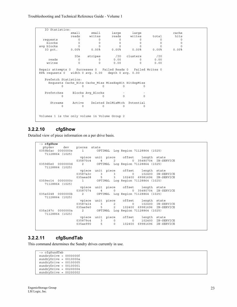
IO Statistics: small small large large cache reads writes reads writes total hits requests 0 0 0 0 0 0 blocks 0 0 0 0 0 0 avg blocks 0 0 0 0 0 0 IO pct. 0.00% 0.00% 0.00% 0.00% 0.00% 0.00% IOs stripes /IO clusters /IO reads 0 0 0.00 0 0.00 writes 0 0 0.00 0 0.00 Repair attempts 0 Successes 0 Failed Reads 0 Failed Writes 0 RPA requests 0 width 0 avg. 0.00 depth 0 avg. 0.00 Prefetch Statistics: Requests Cache_Hits Cache_Miss MissExpHit HitExpMiss 0 0 0 0 0 Prefetches Blocks Avg_Blocks - - 0 0 0 0 0 Streams Active Deleted DelMisMtch Potential 0 0 0 0 0 Volumes 1 is the only volume in Volume Group 2
3.2.2.10 cfgShow Detailed view of piece information on a per drive basis.
-> cfgShow phydev dev pieces state 0359bfac 0000000e 1 OPTIMAL Log Region 71128864 (1025) 71128864 (1025) vpiece unit piece offset length state 035870c4 4 2 0 35480704 IN-SERVICE 0359d5e0 0000000d 2 OPTIMAL Log Region 71128864 (1025) 71128864 (1025) vpiece unit piece offset length state 03587a3c 3 3 0 102400 IN-SERVICE 035aea08 5 3 102400 69981696 IN-SERVICE 0359ec14 0000000c 1 OPTIMAL Log Region 71128864 (1025) 71128864 (1025) vpiece unit piece offset length state 03587074 4 0 0 35480704 IN-SERVICE 035a0248 0000000b 2 OPTIMAL Log Region 71128864 (1025) 71128864 (1025) vpiece unit piece offset length state 03587a14 3 2 0 102400 IN-SERVICE 035ae9e0 5 2 102400 69981696 IN-SERVICE 035a187c 0000000a 2 OPTIMAL Log Region 71128864 (1025) 71128864 (1025) vpiece unit piece offset length state 035879c4 3 0 0 102400 IN-SERVICE 035ae990 5 0 102400 69981696 IN-SERVICE
3.2.2.11 cfgSundTab This command determines the Sundry drives currently in use.
-> cfgSundTab sundryDrive = 0000000f sundryDrive = 0010000a sundryDrive = 00100005 sundryDrive = 00100001 sundryDrive = 00200004 sundryDrive = 00200002
EngenioStorage Group LSI Logic, Inc.
23
Troubleshooting and Technical Reference Guide - Volume 1
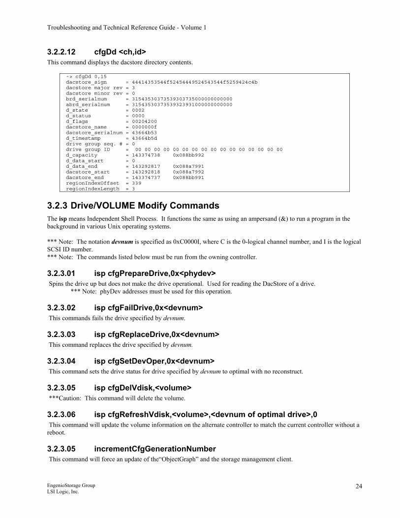
3.2.2.12 cfgDd <ch,id> This command displays the dacstore directory contents.
-> cfgDd 0,15 dacstore_sign = 44414353544f52454449524543544f5259424c4b dacstore major rev = 3 dacstore minor rev = 0 brd_serialnum = 31543530373539303735000000000000 abrd_serialnum = 31543530373539323931000000000000 d_state = 0002 d_status = 0000 d_flags = 00204200 dacstore_name = 0000000f dacstore_serialnum = 43664b53 d_timestamp = 43664b5d drive group seq. # = 0 drive group ID = 00 00 00 00 00 00 00 00 00 00 00 00 00 00 00 00 d_capacity = 143374738 0x088bb992 d_data_start = 0 d_data_end = 143292817 0x088a7991 dacstore_start = 143292818 0x088a7992 dacstore_end = 143374737 0x088bb991 regionIndexOffset = 339 regionIndexLength = 3
3.2.3 Drive/VOLUME Modify Commands The isp means Independent Shell Process. It functions the same as using an ampersand (&) to run a program in the background in various Unix operating systems. *** Note: The notation devnum is specified as 0xC0000I, where C is the 0-logical channel number, and I is the logical SCSI ID number. *** Note: The commands listed below must be run from the owning controller.
3.2.3.01 isp cfgPrepareDrive,0x<phydev> Spins the drive up but does not make the drive operational. Used for reading the DacStore of a drive.
*** Note: phyDev addresses must be used for this operation.
3.2.3.02 isp cfgFailDrive,0x<devnum> This commands fails the drive specified by devnum.
3.2.3.03 isp cfgReplaceDrive,0x<devnum> This command replaces the drive specified by devnum.
3.2.3.04 isp cfgSetDevOper,0x<devnum> This command sets the drive status for drive specified by devnum to optimal with no reconstruct.
3.2.3.05 isp cfgDelVdisk,<volume> ***Caution: This command will delete the volume.
3.2.3.06 isp cfgRefreshVdisk,<volume>,<devnum of optimal drive>,0 This command will update the volume information on the alternate controller to match the current controller without a reboot.
3.2.3.05 incrementCfgGenerationNumber This command will force an update of the“ObjectGraph” and the storage management client.
EngenioStorage Group LSI Logic, Inc.
24
Troubleshooting and Technical Reference Guide - Volume 1
3.2.4 Controller/RDAC Status Commands
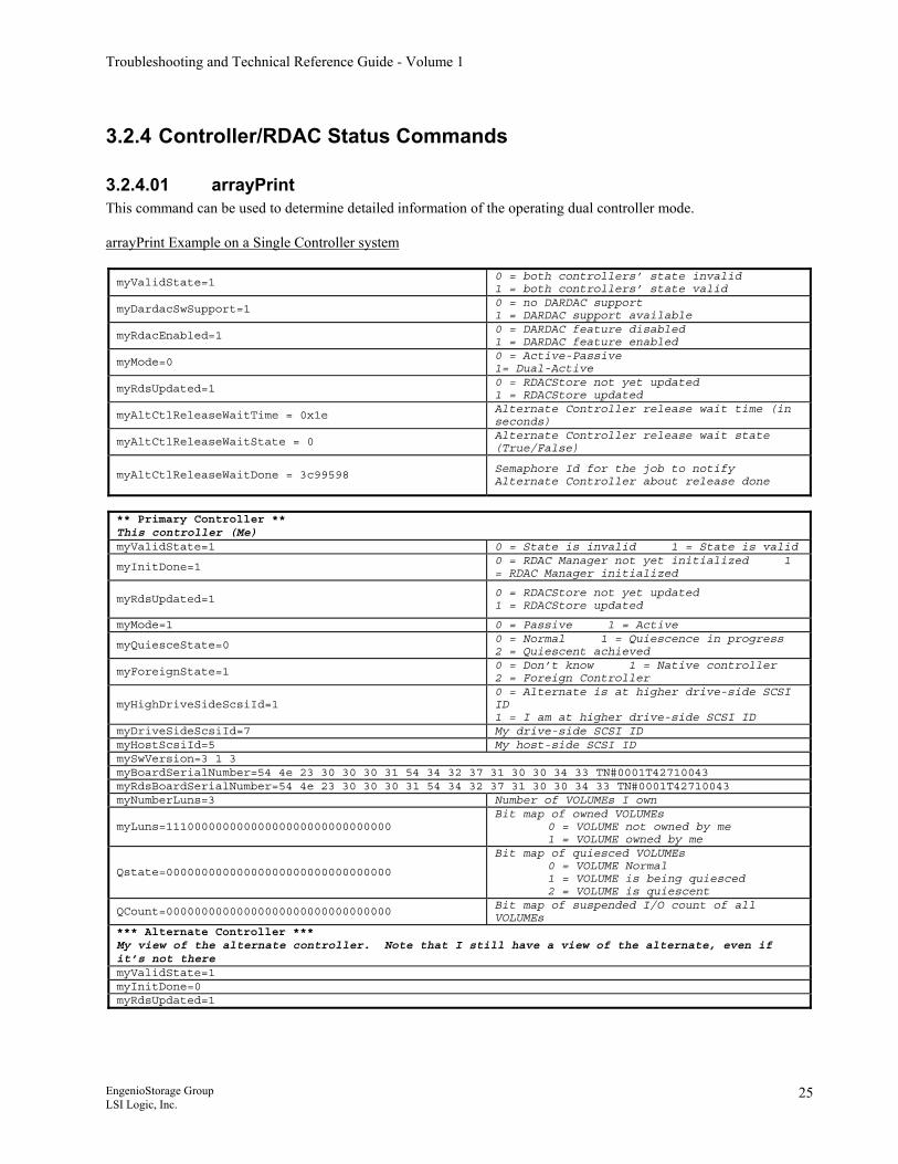
3.2.4.01 arrayPrint This command can be used to determine detailed information of the operating dual controller mode. arrayPrint Example on a Single Controller system myValidState=1
0 = both controllers’ state invalid 1 = both controllers’ state valid
myDardacSwSupport=1 0 = no DARDAC support 1 = DARDAC support available
myRdacEnabled=1 0 = DARDAC feature disabled 1 = DARDAC feature enabled
myMode=0 0 = Active-Passive 1= Dual-Active
myRdsUpdated=1 0 = RDACStore not yet updated 1 = RDACStore updated
myAltCtlReleaseWaitTime = 0x1e Alternate Controller release wait time (in seconds)
myAltCtlReleaseWaitState = 0 Alternate Controller release wait state (True/False)
myAltCtlReleaseWaitDone = 3c99598 Semaphore Id for the job to notify Alternate Controller about release done
** Primary Controller ** This controller (Me) myValidState=1 0 = State is invalid 1 = State is valid
myInitDone=1 0 = RDAC Manager not yet initialized 1 = RDAC Manager initialized
myRdsUpdated=1 0 = RDACStore not yet updated 1 = RDACStore updated
myMode=1 0 = Passive 1 = Active
myQuiesceState=0 0 = Normal 1 = Quiescence in progress 2 = Quiescent achieved
myForeignState=1 0 = Don’t know 1 = Native controller 2 = Foreign Controller
myHighDriveSideScsiId=1 0 = Alternate is at higher drive-side SCSI ID 1 = I am at higher drive-side SCSI ID
myDriveSideScsiId=7 My drive-side SCSI ID myHostScsiId=5 My host-side SCSI ID mySwVersion=3 1 3 myBoardSerialNumber=54 4e 23 30 30 30 31 54 34 32 37 31 30 30 34 33 TN#0001T42710043 myRdsBoardSerialNumber=54 4e 23 30 30 30 31 54 34 32 37 31 30 30 34 33 TN#0001T42710043 myNumberLuns=3 Number of VOLUMEs I own
myLuns=11100000000000000000000000000000 Bit map of owned VOLUMEs
0 = VOLUME not owned by me 1 = VOLUME owned by me
Qstate=00000000000000000000000000000000
Bit map of quiesced VOLUMEs 0 = VOLUME Normal 1 = VOLUME is being quiesced 2 = VOLUME is quiescent
QCount=00000000000000000000000000000000 Bit map of suspended I/O count of all VOLUMEs
*** Alternate Controller *** My view of the alternate controller. Note that I still have a view of the alternate, even if it’s not there myValidState=1 myInitDone=0 myRdsUpdated=1
EngenioStorage Group LSI Logic, Inc.
25
Troubleshooting and Technical Reference Guide - Volume 1
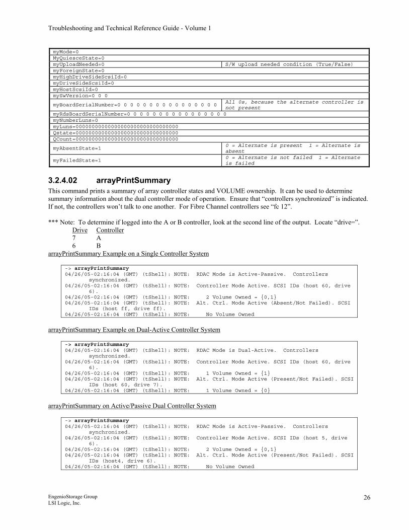
myMode=0 MyQuiesceState=0 myUploadNeeded=0 S/W upload needed condition (True/False) myForeignState=0 myHighDriveSideScsiId=0 myDriveSideScsiId=0 myHostScsiId=0 mySwVersion=0 0 0
myBoardSerialNumber=0 0 0 0 0 0 0 0 0 0 0 0 0 0 0 0 All 0s, because the alternate controller is not present
myRdsBoardSerialNumber=0 0 0 0 0 0 0 0 0 0 0 0 0 0 0 0 myNumberLuns=0 myLuns=00000000000000000000000000000000 Qstate=00000000000000000000000000000000 QCount=00000000000000000000000000000000
myAbsentState=1 0 = Alternate is present 1 = Alternate is absent
myFailedState=1 0 = Alternate is not failed 1 = Alternate is failed
3.2.4.02 arrayPrintSummary This command prints a summary of array controller states and VOLUME ownership. It can be used to determine summary information about the dual controller mode of operation. Ensure that “controllers synchronized” is indicated. If not, the controllers won’t talk to one another. For Fibre Channel controllers see “fc 12”. *** Note: To determine if logged into the A or B controller, look at the second line of the output. Locate “drive=”.
Drive Controller 7 A 6 B
arrayPrintSummary Example on a Single Controller System
-> arrayPrintSummary 04/26/05-02:16:04 (GMT) (tShell): NOTE: RDAC Mode is Active-Passive. Controllers
synchronized. 04/26/05-02:16:04 (GMT) (tShell): NOTE: Controller Mode Active. SCSI IDs (host 60, drive
6). 04/26/05-02:16:04 (GMT) (tShell): NOTE: 2 Volume Owned = {0,1} 04/26/05-02:16:04 (GMT) (tShell): NOTE: Alt. Ctrl. Mode Active (Absent/Not Failed). SCSI
IDs (host ff, drive ff). 04/26/05-02:16:04 (GMT) (tShell): NOTE: No Volume Owned
arrayPrintSummary Example on Dual-Active Controller System
-> arrayPrintSummary 04/26/05-02:16:04 (GMT) (tShell): NOTE: RDAC Mode is Dual-Active. Controllers
synchronized. 04/26/05-02:16:04 (GMT) (tShell): NOTE: Controller Mode Active. SCSI IDs (host 60, drive
6). 04/26/05-02:16:04 (GMT) (tShell): NOTE: 1 Volume Owned = {1} 04/26/05-02:16:04 (GMT) (tShell): NOTE: Alt. Ctrl. Mode Active (Present/Not Failed). SCSI
IDs (host 60, drive 7). 04/26/05-02:16:04 (GMT) (tShell): NOTE: 1 Volume Owned = {0}
arrayPrintSummary on Active/Passive Dual Controller System
-> arrayPrintSummary 04/26/05-02:16:04 (GMT) (tShell): NOTE: RDAC Mode is Active-Passive. Controllers
synchronized. 04/26/05-02:16:04 (GMT) (tShell): NOTE: Controller Mode Active. SCSI IDs (host 5, drive
6). 04/26/05-02:16:04 (GMT) (tShell): NOTE: 2 Volume Owned = {0,1} 04/26/05-02:16:04 (GMT) (tShell): NOTE: Alt. Ctrl. Mode Active (Present/Not Failed). SCSI
IDs (host4, drive 6). 04/26/05-02:16:04 (GMT) (tShell): NOTE: No Volume Owned
EngenioStorage Group LSI Logic, Inc.
26
Troubleshooting and Technical Reference Guide - Volume 1
3.2.5 Controller/RDAC Modify Commands
3.2.5.01 isp rdacMgrSetModeActivePassive This command sets the controller (that you are talking to) to active mode and the alternate controller mode to passive.
WARNING*** This command does not modify the controller cache setup, only the controller states. This may be accomplished by issuing the following command:
isp ccmEventNotify,0x0f
3.2.5.02 isp rdacMgrSetModeDualActive This command sets both array controller modes to dual active.
WARNING*** This command does not modify the controller cache setup, only the controller states. This may be accomplished by issuing the following command:
isp ccmEventNotify,0x0f
3.2.5.03 isp rdacMgrAltCtlFail Will fail the alternate controller and takes ownership of it’s volumes.
NOTE: In order to fail a controller, it may be necessary to set the controller to a passive state first.
3.2.5.04 isp rdacMgrAltCtlResetRelease Will release the alternate controller if it is being held in reset or failed.
3.2.5.05 acsAutoCodeSync When a new (foreign) controller is inserted into a storage array, this command is automatically executed. This command will update the code level of the firmware, either up or down on revision level, to match the code level of the surviving controller. It is also possible to manually run this command from the controller that is to be updated.
3.2.5.06 isp rdacMgrAltCtlReset This command will reboot the alternate controller.
3.2.6 Other Useful Shell Commands and Procedures
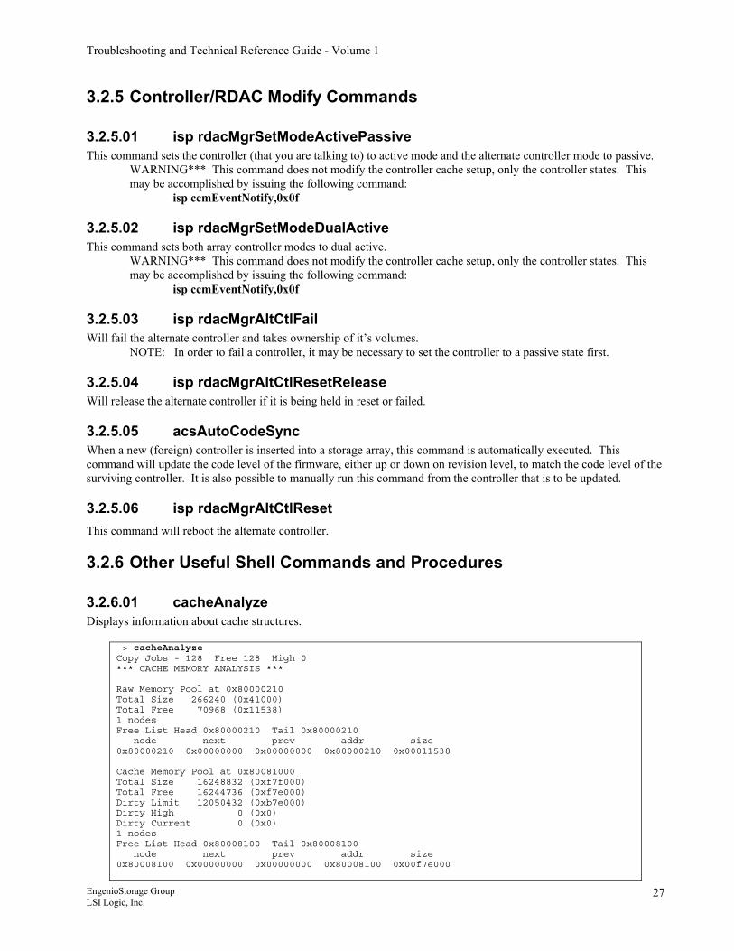
3.2.6.01 cacheAnalyze Displays information about cache structures.
-> cacheAnalyze Copy Jobs - 128 Free 128 High 0 *** CACHE MEMORY ANALYSIS *** Raw Memory Pool at 0x80000210 Total Size 266240 (0x41000) Total Free 70968 (0x11538) 1 nodes Free List Head 0x80000210 Tail 0x80000210 node next prev addr size 0x80000210 0x00000000 0x00000000 0x80000210 0x00011538 Cache Memory Pool at 0x80081000 Total Size 16248832 (0xf7f000) Total Free 16244736 (0xf7e000) Dirty Limit 12050432 (0xb7e000) Dirty High 0 (0x0) Dirty Current 0 (0x0) 1 nodes Free List Head 0x80008100 Tail 0x80008100 node next prev addr size 0x80008100 0x00000000 0x00000000 0x80008100 0x00f7e000
EngenioStorage Group LSI Logic, Inc.
27
Troubleshooting and Technical Reference Guide - Volume 1
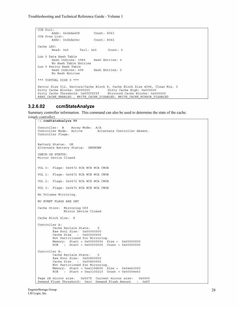
CCB Pool: Addr: 0x3bda4f8 Count: 8063 CCB Free List: Addr: 0x3bda54c Count: 8062 Cache LRU: Head: 0x0 Tail: 0x0 Count: 0 Lun 0 Data Hash Table Hash Indices: 3989 Hash Entries: 0 No Hash Table Entries Lun 0 Parity Hash Table Hash Indices: 499 Hash Entries: 0 No Hash Entries *** VIRTUAL DISK 0 *** Sector Size 512, Sectors/Cache Block 8, Cache Block Size 4096, Clean Min. 0 Dirty Cache Blocks: 0x000000 Dirty Cache High: 0x000000 Dirty Cache Threshold: 0xffffffff Mirrored Cache Blocks: 0x000000 READ_CACHE_ENABLED , WRITE_CACHE_DISABLED, WRITE_CACHE_MIRROR_DISABLED
3.2.6.02 ccmStateAnalyze Summary controller information. This command can also be used to determine the state of the cache. (single controller)
-> ccmStateAnalyze 99 Controller: B Array Mode: A/A Controller Mode: Active Alternate Controller Absent. Controller Flags: Battery Status: OK Alternate Battery Status: UNKNOWN CHECK-IN STATUS: Mirror Device Closed VOL 0: Flags: 0x0472 RCA WCE WCA CWOB VOL 1: Flags: 0x0472 RCA WCE WCA CWOB VOL 2: Flags: 0x0472 RCA WCE WCA CWOB VOL 3: Flags: 0x0472 RCA WCE WCA CWOB No Volumes Mirroring. NO EVENT FLAGS ARE SET Cache Store: Mirroring Off Mirror Device Closed Cache Block Size: 8 Controller A: Cache Reclaim State: 0 Raw Pool Size: 0x00000000 Cache Size : 0x00000000 Not Partitioned for Mirroring. Memory: Start = 0x00000000 Size = 0x00000000 RCB : Start = 0x00000000 Count = 0x00000000 Controller B: Cache Reclaim State: 0 Raw Pool Size: 0x00800000 Cache Size : 0x05800000 Not Partitioned for Mirroring. Memory: Start = 0xa319d000 Size = 0x04e63000 RCB : Start = 0xa3100210 Count = 0x00004e63 Page 2E mirror size: 0x007f Current mirror size: 0x0000 Demand Flush Threshold: 0xcc Demand Flush Amount : 0xff
EngenioStorage Group LSI Logic, Inc.
28
Troubleshooting and Technical Reference Guide - Volume 1
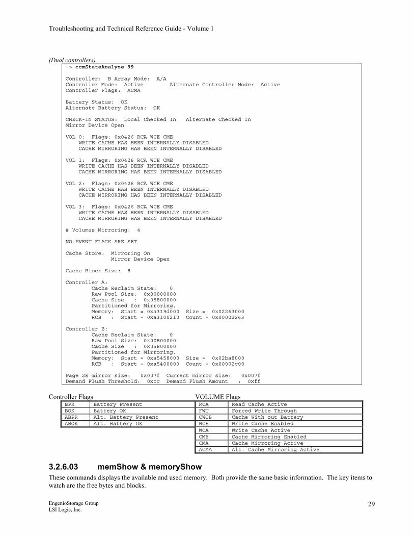
(Dual controllers)
-> ccmStateAnalyze 99 Controller: B Array Mode: A/A Controller Mode: Active Alternate Controller Mode: Active Controller Flags: ACMA Battery Status: OK Alternate Battery Status: OK CHECK-IN STATUS: Local Checked In Alternate Checked In Mirror Device Open VOL 0: Flags: 0x0426 RCA WCE CME WRITE CACHE HAS BEEN INTERNALLY DISABLED CACHE MIRRORING HAS BEEN INTERNALLY DISABLED VOL 1: Flags: 0x0426 RCA WCE CME WRITE CACHE HAS BEEN INTERNALLY DISABLED CACHE MIRRORING HAS BEEN INTERNALLY DISABLED VOL 2: Flags: 0x0426 RCA WCE CME WRITE CACHE HAS BEEN INTERNALLY DISABLED CACHE MIRRORING HAS BEEN INTERNALLY DISABLED VOL 3: Flags: 0x0426 RCA WCE CME WRITE CACHE HAS BEEN INTERNALLY DISABLED CACHE MIRRORING HAS BEEN INTERNALLY DISABLED # Volumes Mirroring: 4 NO EVENT FLAGS ARE SET Cache Store: Mirroring On Mirror Device Open Cache Block Size: 8 Controller A: Cache Reclaim State: 0 Raw Pool Size: 0x00800000 Cache Size : 0x05800000 Partitioned for Mirroring. Memory: Start = 0xa319d000 Size = 0x02263000 RCB : Start = 0xa3100210 Count = 0x00002263 Controller B: Cache Reclaim State: 0 Raw Pool Size: 0x00800000 Cache Size : 0x05800000 Partitioned for Mirroring. Memory: Start = 0xa5458000 Size = 0x02ba8000 RCB : Start = 0xa5400000 Count = 0x00002c00 Page 2E mirror size: 0x007f Current mirror size: 0x007f Demand Flush Threshold: 0xcc Demand Flush Amount : 0xff
Controller Flags VOLUME Flags
BPR Battery Present RCA Read Cache Active BOK Battery OK FWT Forced Write Through ABPR Alt. Battery Present CWOB Cache With out Battery ABOK Alt. Battery OK WCE Write Cache Enabled
WCA Write Cache Active CME Cache Mirroring Enabled CMA Cache Mirroring Active
ACMA Alt. Cache Mirroring Active
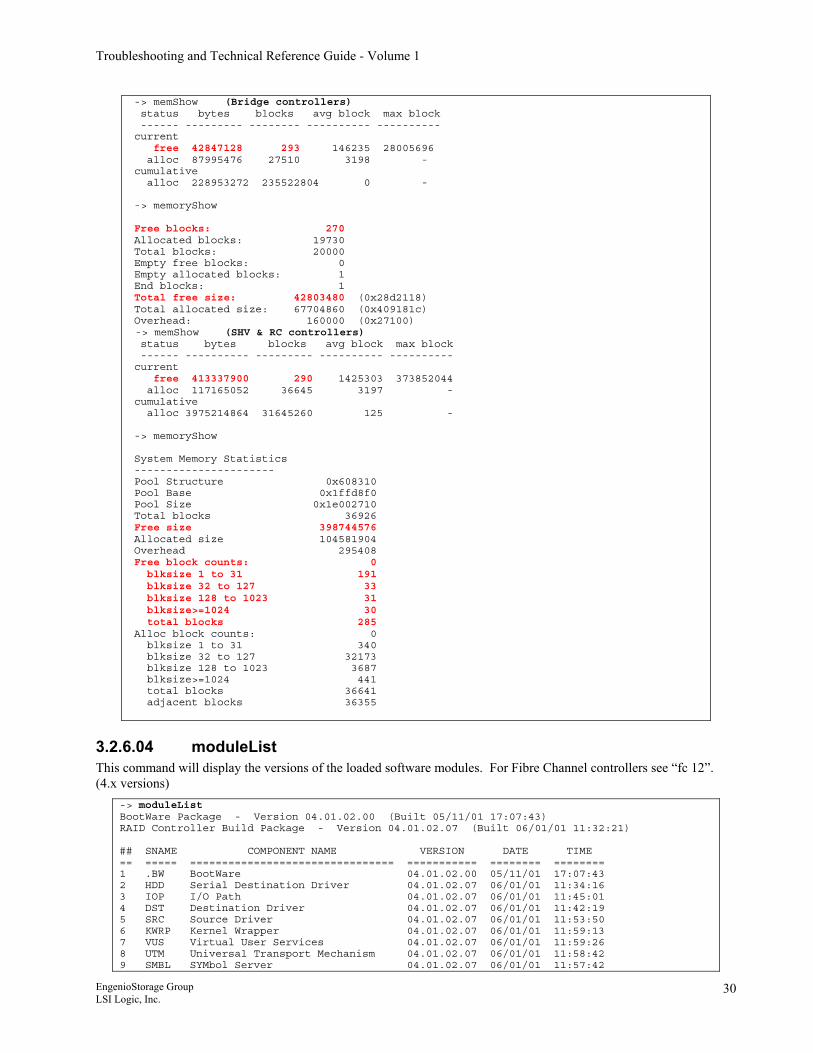
3.2.6.03 memShow & memoryShow These commands displays the available and used memory. Both provide the same basic information. The key items to watch are the free bytes and blocks. EngenioStorage Group LSI Logic, Inc.
29
Troubleshooting and Technical Reference Guide - Volume 1
-> memShow (Bridge controllers) status bytes blocks avg block max block ------ --------- -------- ---------- ---------- current free 42847128 293 146235 28005696 alloc 87995476 27510 3198 - cumulative alloc 228953272 235522804 0 - -> memoryShow Free blocks: 270 Allocated blocks: 19730 Total blocks: 20000 Empty free blocks: 0 Empty allocated blocks: 1 End blocks: 1 Total free size: 42803480 (0x28d2118) Total allocated size: 67704860 (0x409181c) Overhead: 160000 (0x27100) -> memShow (SHV & RC controllers) status bytes blocks avg block max block ------ ---------- --------- ---------- ---------- current free 413337900 290 1425303 373852044 alloc 117165052 36645 3197 - cumulative alloc 3975214864 31645260 125 - -> memoryShow System Memory Statistics ---------------------- Pool Structure 0x608310 Pool Base 0x1ffd8f0 Pool Size 0x1e002710 Total blocks 36926 Free size 398744576 Allocated size 104581904 Overhead 295408 Free block counts: 0 blksize 1 to 31 191 blksize 32 to 127 33 blksize 128 to 1023 31 blksize>=1024 30 total blocks 285 Alloc block counts: 0 blksize 1 to 31 340 blksize 32 to 127 32173 blksize 128 to 1023 3687 blksize>=1024 441 total blocks 36641 adjacent blocks 36355
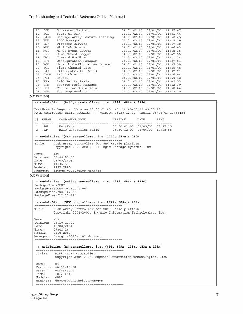
3.2.6.04 moduleList This command will display the versions of the loaded software modules. For Fibre Channel controllers see “fc 12”. (4.x versions)
-> moduleList BootWare Package - Version 04.01.02.00 (Built 05/11/01 17:07:43) RAID Controller Build Package - Version 04.01.02.07 (Built 06/01/01 11:32:21) ## SNAME COMPONENT NAME VERSION DATE TIME == ===== ================================ =========== ======== ======== 1 .BW BootWare 04.01.02.00 05/11/01 17:07:43 2 HDD Serial Destination Driver 04.01.02.07 06/01/01 11:34:16 3 IOP I/O Path 04.01.02.07 06/01/01 11:45:01 4 DST Destination Driver 04.01.02.07 06/01/01 11:42:19 5 SRC Source Driver 04.01.02.07 06/01/01 11:53:50 6 KWRP Kernel Wrapper 04.01.02.07 06/01/01 11:59:13 7 VUS Virtual User Services 04.01.02.07 06/01/01 11:59:26 8 UTM Universal Transport Mechanism 04.01.02.07 06/01/01 11:58:42 9 SMBL SYMbol Server 04.01.02.07 06/01/01 11:57:42
EngenioStorage Group LSI Logic, Inc.
30
Troubleshooting and Technical Reference Guide - Volume 1
10 SSM Subsystem Monitor 04.01.02.07 06/01/01 11:55:07 11 SOD Start of Day 04.01.02.07 06/01/01 11:51:44 12 SAFE Storage Array Feature Enabling 04.01.02.07 06/01/01 11:50:45 13 RDM RDAC Manager 04.01.02.07 06/01/01 11:49:19 14 PSV Platform Service 04.01.02.07 06/01/01 11:47:10 15 MHM Mini Hub Manager 04.01.02.07 06/01/01 11:46:03 16 Mel Major Event Logger 04.01.02.07 06/01/01 11:45:35 17 EEL Error/Event Logger 04.01.02.07 06/01/01 11:42:56 18 CMD Command Handlers 04.01.02.07 06/01/01 11:41:34 19 CFG Configuration Manager 04.01.02.07 06/01/01 11:37:51 20 NCM Network Configuration Manager 04.01.02.07 06/01/01 12:07:58 21 FCL Fibre Channel Lite 04.01.02.07 06/01/01 11:59:45 22 .AP RAID Controller Build 04.01.02.07 06/01/01 11:32:21 23 CACH I/O Caching 04.01.02.07 06/01/01 11:36:04 24 RTR Router 04.01.02.07 06/01/01 11:50:12 25 RPA Raid Parity Assist 04.01.02.07 06/01/01 11:49:53 26 SPM Storage Pools Manager 04.01.02.07 06/01/01 11:52:39 27 CSP Controller State Print 04.01.02.07 06/01/01 11:58:04 28 HSM Hot Swap Monitor 04.01.02.07 06/01/01 11:43:10
(5.x version) -> moduleList (Bridge controllers, i.e. 4774, 4884 & 5884) BootWare Package - Version 05.30.01.00 (Built 09/05/03 09:55:19) RAID Controller Build Package - Version 05.30.12.00 (Built 05/06/03 12:58:58) ## SNAME COMPONENT NAME VERSION DATE TIME == ====== ========================== =========== ======== ======== 1 .BW BootWare 05.30.01.00 09/05/03 09:55:19 2 .AP RAID Controller Build 05.30.12.00 05/06/03 12:58:58 -> moduleList (SHV controllers, i.e. 2772, 288x & 282x) ============================================== Title: Disk Array Controller for SHV XScale platform Copyright 2002-2003, LSI Logic Storage Systems, Inc. Name: shv Version: 05.40.03.00 Date: 08/05/2003 Time: 14:36:51 Models: 2882 2880 Manager: devmgr.v0840api09.Manager
(6.x version) -> moduleList (Bridge controllers, i.e. 4774, 4884 & 5884) PackageName="FW" PackageVersion="06.10.05.00" PackageDate="08/10/04" PackageTime="12:11:39" -> moduleList (SHV controllers, i.e. 2772, 288x & 282x) ============================================== Title: Disk Array Controller for SHV XScale platform Copyright 2001-2004, Engenio Information Technologies, Inc. Name: shv Version: 06.10.11.00 Date: 11/08/2004 Time: 09:42:16 Models: 2880 2882 Manager: devmgr.v0910api01.Manager ============================================== -> moduleList (RC controllers, i.e. 6091, 399x, 133x, 153x & 193x) ============================================== Title: Disk Array Controller Copyright 2004-2005, Engenio Information Technologies, Inc. Name: RC Version: 06.14.15.00 Date: 04/06/2005 Time: 10:23:41 Models: 6091 Manager: devmgr.v0914api00.Manager ==============================================
EngenioStorage Group LSI Logic, Inc.
31
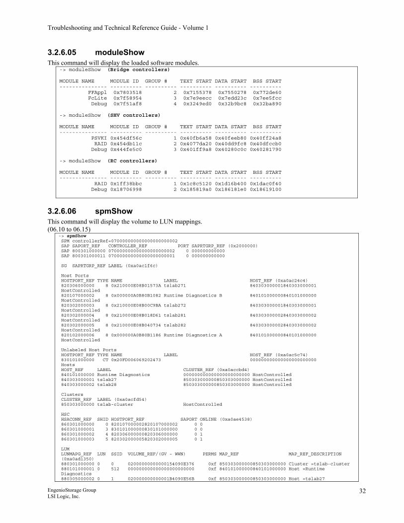
Troubleshooting and Technical Reference Guide - Volume 1
3.2.6.05 moduleShow This command will display the loaded software modules.
-> moduleShow (Bridge controllers) MODULE NAME MODULE ID GROUP # TEXT START DATA START BSS START --------------- ---------- ---------- ---------- ---------- ---------- FFAppl 0x7803518 2 0x7155378 0x7550278 0x772de60 FcLite 0x7f58954 3 0x7e9eecc 0x7edd23c 0x7ee5fcc Debug 0x7f51af8 4 0x3249ed0 0x32b9bc8 0x32ba890 -> moduleShow (SHV controllers) MODULE NAME MODULE ID GROUP # TEXT START DATA START BSS START --------------- ---------- ---------- ---------- ---------- ---------- PSVKI 0x454df56c 1 0x40fb6a58 0x40feeb80 0x40ff24a8 RAID 0x454db11c 2 0x4077da20 0x40dd9fc8 0x40dfccb0 Debug 0x444fe5c0 3 0x401ff9a8 0x40280c0c 0x40281790 -> moduleShow (RC controllers) MODULE NAME MODULE ID GROUP # TEXT START DATA START BSS START --------------- ---------- ---------- ---------- ---------- ---------- RAID 0x1ff38bbc 1 0x1c8c5120 0x1d16b400 0x1dac0f40 Debug 0x18706998 2 0x185819a0 0x186181e0 0x18619100
3.2.6.06 spmShow This command will display the volume to LUN mappings. (06.10 to 06.15)
-> spmShow SPM controllerRef=070000000000000000000002 SAP SAPORT_REF CONTROLLER_REF PORT SAPRTGRP_REF (0x2000000) SAP 800301000000 070000000000000000000002 0 000000000000 SAP 800301000011 070000000000000000000001 0 000000000000 SG SAPRTGRP_REF LABEL (0xa0ac1f6c) Host Ports HOSTPORT_REF TYPE NAME LABEL HOST_REF (0xa0ac24c4) 820306000000 8 0x210000E08B01573A tslab271 840303000001840303000001 HostControlled 820107000002 8 0x000000A0B80B1082 Runtime Diagnostics B 840101000000840101000000 HostControlled 820302000003 8 0x210000E08B00C9BA tslab272 840303000001840303000001 HostControlled 820302000004 8 0x210000E08B018D61 tslab281 840303000002840303000002 HostControlled 820302000005 8 0x210000E08B040734 tslab282 840303000002840303000002 HostControlled 820102000006 8 0x000000A0B80B1186 Runtime Diagnostics A 840101000000840101000000 HostControlled Unlabeled Host Ports HOSTPORT_REF TYPE NAME LABEL HOST_REF (0xa0ac5c74) 830101000000 CT 0x20FD006069202473 000000000000000000000000 Hosts HOST_REF LABEL CLUSTER_REF (0xa0accbd4) 840101000000 Runtime Diagnostics 000000000000000000000000 HostControlled 840303000001 tslab27 850303000000850303000000 HostControlled 840303000002 tslab28 850303000000850303000000 HostControlled Clusters CLUSTER_REF LABEL (0xa0acfd54) 850303000000 tslab-cluster HostControlled HSC HSACONN_REF SHID HOSTPORT_REF SAPORT ONLINE (0xa0ae4538) 860301000000 0 820107000002820107000002 0 0 860301000001 3 830101000000830101000000 0 0 860301000002 4 820306000000820306000000 0 1 860301000003 5 820302000005820302000005 0 1 LUM LUNMAPG_REF LUN SSID VOLUME_REF/(GV - WWN) PERMS MAP_REF MAP_REF_DESCRIPTION (0xa0ad1350) 880301000000 0 0 02000000000000154090E376 0xf 850303000000850303000000 Cluster =tslab-cluster 880101000001 0 512 000000000000000000000000 0xf 840101000000840101000000 Host =Runtime Diagnostics 880305000002 0 1 020000000000001B4090E56B 0xf 850303000000850303000000 Host =tslab27
EngenioStorage Group LSI Logic, Inc.
32
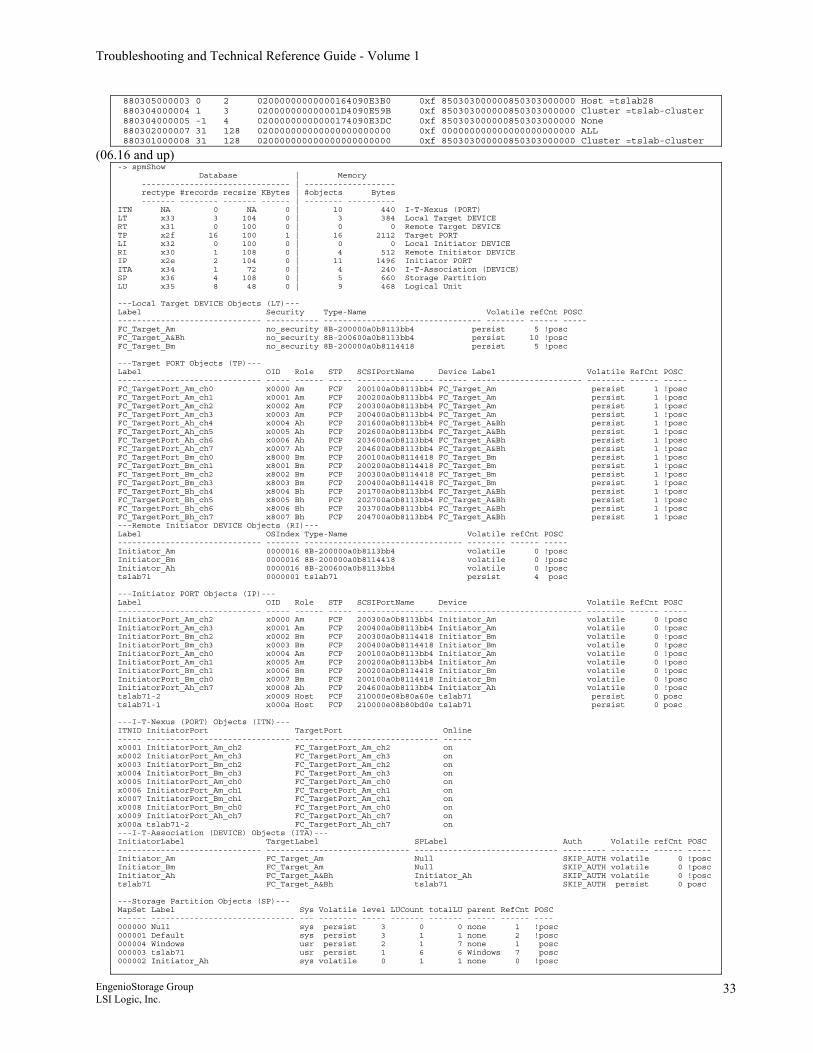
Troubleshooting and Technical Reference Guide - Volume 1
880305000003 0 2 02000000000000164090E3B0 0xf 850303000000850303000000 Host =tslab28 880304000004 1 3 020000000000001D4090E59B 0xf 850303000000850303000000 Cluster =tslab-cluster 880304000005 -1 4 02000000000000174090E3DC 0xf 850303000000850303000000 None 880302000007 31 128 020000000000000000000000 0xf 000000000000000000000000 ALL 880301000008 31 128 020000000000000000000000 0xf 850303000000850303000000 Cluster =tslab-cluster
(06.16 and up) -> spmShow Database | Memory ------------------------------- | ------------------- rectype #records recsize KBytes | #objects Bytes ------- -------- ------- ------ | -------- ---------- ITN NA 0 NA 0 | 10 440 I-T-Nexus (PORT) LT x33 3 104 0 | 3 384 Local Target DEVICE RT x31 0 100 0 | 0 0 Remote Target DEVICE TP x2f 16 100 1 | 16 2112 Target PORT LI x32 0 100 0 | 0 0 Local Initiator DEVICE RI x30 1 108 0 | 4 512 Remote Initiator DEVICE IP x2e 2 104 0 | 11 1496 Initiator PORT ITA x34 1 72 0 | 4 240 I-T-Association (DEVICE) SP x36 4 108 0 | 5 660 Storage Partition LU x35 8 48 0 | 9 468 Logical Unit ---Local Target DEVICE Objects (LT)--- Label Security Type-Name Volatile refCnt POSC ------------------------------ ----------- --------------------------------- -------- ------ ----- FC_Target_Am no_security 8B-200000a0b8113bb4 persist 5 !posc FC_Target_A&Bh no_security 8B-200600a0b8113bb4 persist 10 !posc FC_Target_Bm no_security 8B-200000a0b8114418 persist 5 !posc ---Target PORT Objects (TP)--- Label OID Role STP SCSIPortName Device Label Volatile RefCnt POSC ------------------------------ ----- ------ ----- ---------------- ------ ----------------------- -------- ------ ----- FC_TargetPort_Am_ch0 x0000 Am FCP 200100a0b8113bb4 FC_Target_Am persist 1 !posc FC_TargetPort_Am_ch1 x0001 Am FCP 200200a0b8113bb4 FC_Target_Am persist 1 !posc FC_TargetPort_Am_ch2 x0002 Am FCP 200300a0b8113bb4 FC_Target_Am persist 1 !posc FC_TargetPort_Am_ch3 x0003 Am FCP 200400a0b8113bb4 FC_Target_Am persist 1 !posc FC_TargetPort_Ah_ch4 x0004 Ah FCP 201600a0b8113bb4 FC_Target_A&Bh persist 1 !posc FC_TargetPort_Ah_ch5 x0005 Ah FCP 202600a0b8113bb4 FC_Target_A&Bh persist 1 !posc FC_TargetPort_Ah_ch6 x0006 Ah FCP 203600a0b8113bb4 FC_Target_A&Bh persist 1 !posc FC_TargetPort_Ah_ch7 x0007 Ah FCP 204600a0b8113bb4 FC_Target_A&Bh persist 1 !posc FC_TargetPort_Bm_ch0 x8000 Bm FCP 200100a0b8114418 FC_Target_Bm persist 1 !posc FC_TargetPort_Bm_ch1 x8001 Bm FCP 200200a0b8114418 FC_Target_Bm persist 1 !posc FC_TargetPort_Bm_ch2 x8002 Bm FCP 200300a0b8114418 FC_Target_Bm persist 1 !posc FC_TargetPort_Bm_ch3 x8003 Bm FCP 200400a0b8114418 FC_Target_Bm persist 1 !posc FC_TargetPort_Bh_ch4 x8004 Bh FCP 201700a0b8113bb4 FC_Target_A&Bh persist 1 !posc FC_TargetPort_Bh_ch5 x8005 Bh FCP 202700a0b8113bb4 FC_Target_A&Bh persist 1 !posc FC_TargetPort_Bh_ch6 x8006 Bh FCP 203700a0b8113bb4 FC_Target_A&Bh persist 1 !posc FC_TargetPort_Bh_ch7 x8007 Bh FCP 204700a0b8113bb4 FC_Target_A&Bh persist 1 !posc ---Remote Initiator DEVICE Objects (RI)--- Label OSIndex Type-Name Volatile refCnt POSC ------------------------------ ------- --------------------------------- -------- ------ ----- Initiator_Am 0000016 8B-200000a0b8113bb4 volatile 0 !posc Initiator_Bm 0000016 8B-200000a0b8114418 volatile 0 !posc Initiator_Ah 0000016 8B-200600a0b8113bb4 volatile 0 !posc tslab71 0000001 tslab71 persist 4 posc ---Initiator PORT Objects (IP)--- Label OID Role STP SCSIPortName Device Volatile RefCnt POSC ------------------------------ ----- ------ ----- ---------------- ------------------------------ -------- ------ ----- InitiatorPort_Am_ch2 x0000 Am FCP 200300a0b8113bb4 Initiator_Am volatile 0 !posc InitiatorPort_Am_ch3 x0001 Am FCP 200400a0b8113bb4 Initiator_Am volatile 0 !posc InitiatorPort_Bm_ch2 x0002 Bm FCP 200300a0b8114418 Initiator_Bm volatile 0 !posc InitiatorPort_Bm_ch3 x0003 Bm FCP 200400a0b8114418 Initiator_Bm volatile 0 !posc InitiatorPort_Am_ch0 x0004 Am FCP 200100a0b8113bb4 Initiator_Am volatile 0 !posc InitiatorPort_Am_ch1 x0005 Am FCP 200200a0b8113bb4 Initiator_Am volatile 0 !posc InitiatorPort_Bm_ch1 x0006 Bm FCP 200200a0b8114418 Initiator_Bm volatile 0 !posc InitiatorPort_Bm_ch0 x0007 Bm FCP 200100a0b8114418 Initiator_Bm volatile 0 !posc InitiatorPort_Ah_ch7 x0008 Ah FCP 204600a0b8113bb4 Initiator_Ah volatile 0 !posc tslab71-2 x0009 Host FCP 210000e08b80a60e tslab71 persist 0 posc tslab71-1 x000a Host FCP 210000e08b80bd0e tslab71 persist 0 posc ---I-T-Nexus (PORT) Objects (ITN)--- ITNID InitiatorPort TargetPort Online ----- ------------------------------ ------------------------------ ------ x0001 InitiatorPort_Am_ch2 FC_TargetPort_Am_ch2 on x0002 InitiatorPort_Am_ch3 FC_TargetPort_Am_ch3 on x0003 InitiatorPort_Bm_ch2 FC_TargetPort_Am_ch2 on x0004 InitiatorPort_Bm_ch3 FC_TargetPort_Am_ch3 on x0005 InitiatorPort_Am_ch0 FC_TargetPort_Am_ch0 on x0006 InitiatorPort_Am_ch1 FC_TargetPort_Am_ch1 on x0007 InitiatorPort_Bm_ch1 FC_TargetPort_Am_ch1 on x0008 InitiatorPort_Bm_ch0 FC_TargetPort_Am_ch0 on x0009 InitiatorPort_Ah_ch7 FC_TargetPort_Ah_ch7 on x000a tslab71-2 FC_TargetPort_Ah_ch7 on ---I-T-Association (DEVICE) Objects (ITA)--- InitiatorLabel TargetLabel SPLabel Auth Volatile refCnt POSC ------------------------------ ------------------------------ ------------------------------ --------- -------- ------ ----- Initiator_Am FC_Target_Am Null SKIP_AUTH volatile 0 !posc Initiator_Bm FC_Target_Am Null SKIP_AUTH volatile 0 !posc Initiator_Ah FC_Target_A&Bh Initiator_Ah SKIP_AUTH volatile 0 !posc tslab71 FC_Target_A&Bh tslab71 SKIP_AUTH persist 0 posc ---Storage Partition Objects (SP)--- MapSet Label Sys Volatile level LUCount totalLU parent RefCnt POSC ------ ------------------------------ --- -------- ----- ------- ------- ------ ------ ---- 000000 Null sys persist 3 0 0 none 1 !posc 000001 Default sys persist 3 1 1 none 2 !posc 000004 Windows usr persist 2 1 7 none 1 posc 000003 tslab71 usr persist 1 6 6 Windows 7 posc 000002 Initiator_Ah sys volatile 0 1 1 none 0 !posc
EngenioStorage Group LSI Logic, Inc.
33
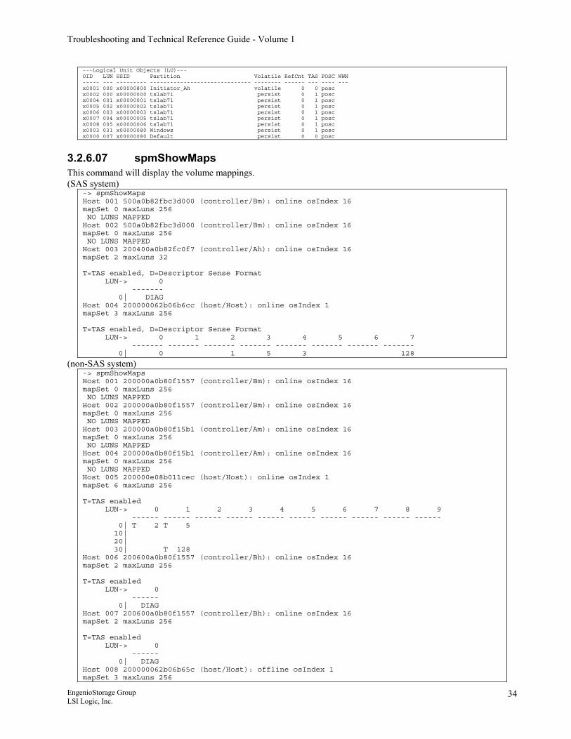
Troubleshooting and Technical Reference Guide - Volume 1
---Logical Unit Objects (LU)--- OID LUN SSID Partition Volatile RefCnt TAS POSC WWN ----- --- --------- ------------------------------ -------- ------ --- ---- --- x0001 000 x00000800 Initiator_Ah volatile 0 0 posc x0002 000 x00000000 tslab71 persist 0 1 posc x0004 001 x00000001 tslab71 persist 0 1 posc x0005 002 x00000002 tslab71 persist 0 1 posc x0006 003 x00000003 tslab71 persist 0 1 posc x0007 004 x00000005 tslab71 persist 0 1 posc x0008 005 x00000006 tslab71 persist 0 1 posc x0003 031 x00000080 Windows persist 0 1 posc x0000 007 x00000080 Default persist 0 0 posc
3.2.6.07 spmShowMaps This command will display the volume mappings. (SAS system)
-> spmShowMaps Host 001 500a0b82fbc3d000 (controller/Bm): online osIndex 16 mapSet 0 maxLuns 256 NO LUNS MAPPED Host 002 500a0b82fbc3d000 (controller/Bm): online osIndex 16 mapSet 0 maxLuns 256 NO LUNS MAPPED Host 003 200400a0b82fc0f7 (controller/Ah): online osIndex 16 mapSet 2 maxLuns 32 T=TAS enabled, D=Descriptor Sense Format LUN-> 0 ------- 0| DIAG Host 004 200000062b06b6cc (host/Host): online osIndex 1 mapSet 3 maxLuns 256 T=TAS enabled, D=Descriptor Sense Format LUN-> 0 1 2 3 4 5 6 7 ------- ------- ------- ------- ------- ------- ------- ------- 0| 0 1 5 3 128
(non-SAS system) -> spmShowMaps Host 001 200000a0b80f1557 (controller/Bm): online osIndex 16 mapSet 0 maxLuns 256 NO LUNS MAPPED Host 002 200000a0b80f1557 (controller/Bm): online osIndex 16 mapSet 0 maxLuns 256 NO LUNS MAPPED Host 003 200000a0b80f15b1 (controller/Am): online osIndex 16 mapSet 0 maxLuns 256 NO LUNS MAPPED Host 004 200000a0b80f15b1 (controller/Am): online osIndex 16 mapSet 0 maxLuns 256 NO LUNS MAPPED Host 005 200000e08b011cec (host/Host): online osIndex 1 mapSet 6 maxLuns 256 T=TAS enabled LUN-> 0 1 2 3 4 5 6 7 8 9 ------ ------ ------ ------ ------ ------ ------ ------ ------ ------ 0| T 2 T 5 10| 20| 30| T 128 Host 006 200600a0b80f1557 (controller/Bh): online osIndex 16 mapSet 2 maxLuns 256 T=TAS enabled LUN-> 0 ------ 0| DIAG Host 007 200600a0b80f1557 (controller/Bh): online osIndex 16 mapSet 2 maxLuns 256 T=TAS enabled LUN-> 0 ------ 0| DIAG Host 008 200000062b06b65c (host/Host): offline osIndex 1 mapSet 3 maxLuns 256
EngenioStorage Group LSI Logic, Inc.
34
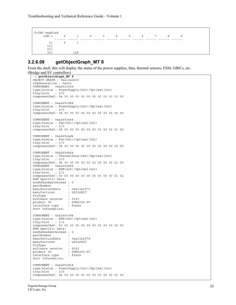
Troubleshooting and Technical Reference Guide - Volume 1
T=TAS enabled LUN-> 0 1 2 3 4 5 6 7 8 9 ------ ------ ------ ------ ------ ------ ------ ------ ------ ------ 0| 0 1 10| 20| 30| 128
3.2.6.08 getObjectGraph_MT 8 From the shell, this will display the status of the power supplies, fans, thermal sensors, ESM, GBICs, etc. (Bridge and SV controllers)
-> getObjectGraph_MT 8 OBJECT GRAPH - 0xa13a1b30 cfgGeneration : 0x21c COMPONENT - 0xa265c924 type/status : PowerSupply(0x3)/Optimal(0x1) tray/slot : 0/0 componentRef: 0a 00 00 00 00 00 00 00 00 00 01 00 COMPONENT - 0xa265c9b4 type/status : PowerSupply(0x3)/Optimal(0x1) tray/slot : 0/0 componentRef: 0a 00 00 00 00 00 00 00 00 00 02 00 COMPONENT - 0xa265ca44 type/status : Fan(0x1)/Optimal(0x1) tray/slot : 0/0 componentRef: 08 00 00 00 00 00 00 00 00 00 01 00 COMPONENT - 0xa265cad4 type/status : Fan(0x1)/Optimal(0x1) tray/slot : 0/0 componentRef: 08 00 00 00 00 00 00 00 00 00 02 00 COMPONENT - 0xa265cb64 type/status : ThermalSens(0x4)/Optimal(0x1) tray/slot : 0/0 componentRef: 0b 00 00 00 00 00 00 00 00 00 01 00 COMPONENT - 0xa265cbf4 type/status : ESM(0x5)/Optimal(0x1) tray/slot : 2/1 componentRef: 0c 00 00 00 00 00 00 00 00 00 01 02 ESM Specific Data: nonRedundantAccess : 0 partNumber : manufactureDate : 0xa13a1f70 manufacturer : LSILOGIC fruType : software version : 9163 product ID : SYM2200-FC interface type : Fibre Port Information: COMPONENT - 0xa265cc84 type/status : ESM(0x5)/Optimal(0x1) tray/slot : 2/2 componentRef: 0c 00 00 00 00 00 00 00 00 00 02 02 ESM Specific Data: nonRedundantAccess : 0 partNumber : manufactureDate : 0xa13a1f70 manufacturer : LSILOGIC fruType : software version : 9163 product ID : SYM2200-FC interface type : Fibre Port Information: COMPONENT - 0xa265cd14 type/status : PowerSupply(0x3)/Optimal(0x1) tray/slot : 2/0 componentRef: 0a 00 00 00 00 00 00 00 00 00 01 02
EngenioStorage Group LSI Logic, Inc.
35
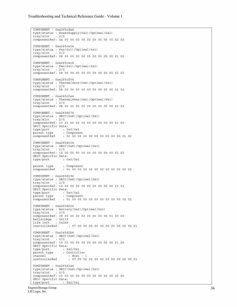
Troubleshooting and Technical Reference Guide - Volume 1
COMPONENT - 0xa265cda4 type/status : PowerSupply(0x3)/Optimal(0x1) tray/slot : 2/0 componentRef: 0a 00 00 00 00 00 00 00 00 00 02 02 COMPONENT - 0xa265ce34 type/status : Fan(0x1)/Optimal(0x1) tray/slot : 2/0 componentRef: 08 00 00 00 00 00 00 00 00 00 01 02 COMPONENT - 0xa265cec4 type/status : Fan(0x1)/Optimal(0x1) tray/slot : 2/0 componentRef: 08 00 00 00 00 00 00 00 00 00 02 02 COMPONENT - 0xa265cf54 type/status : ThermalSens(0x4)/Optimal(0x1) tray/slot : 2/0 componentRef: 0b 00 00 00 00 00 00 00 00 00 01 02 COMPONENT - 0xa265cfe4 type/status : ThermalSens(0x4)/Optimal(0x1) tray/slot : 2/0 componentRef: 0b 00 00 00 00 00 00 00 00 00 02 02 COMPONENT - 0xa265d074 type/status : GBIC(0x8)/Optimal(0x1) tray/slot : 2/0 componentRef: 10 01 00 00 00 00 00 00 00 00 01 02 GBIC Specific Data: type/port : 0x0/0x1 parent type : Component componentRef : 0c 00 00 00 00 00 00 00 00 00 01 02 COMPONENT - 0xa265d104 type/status : GBIC(0x8)/Optimal(0x1) tray/slot : 2/0 componentRef: 10 00 00 00 00 00 00 00 00 00 02 02 GBIC Specific Data: type/port : 0x0/0x1 parent type : Component componentRef : 0c 00 00 00 00 00 00 00 00 00 02 02 COMPONENT - 0xa265d194 type/status : GBIC(0x8)/Optimal(0x1) tray/slot : 2/0 componentRef: 10 00 00 00 00 00 00 00 00 00 03 02 GBIC Specific Data: type/port : 0x0/0x2 parent type : Component componentRef : 0c 00 00 00 00 00 00 00 00 00 02 02 COMPONENT - 0xa265d224 type/status : Battery(0x2)/Optimal(0x1) tray/slot : 0/0 componentRef: 09 00 00 00 00 00 00 00 00 01 00 00 batteryAge : 0x119 life left : 0x1b6 controllerRef : 07 00 00 00 00 00 00 00 00 00 00 01 COMPONENT - 0xa265d2b4 type/status : GBIC(0x8)/Optimal(0x1) tray/slot : 0/0 componentRef: 10 01 00 00 00 00 00 00 00 00 01 00 GBIC Specific Data: type/port : 0x2/0x1 parent type : Controller channel : Host - 1 controllerRef : 07 00 00 00 00 00 00 00 00 00 00 01 COMPONENT - 0xa265d344 type/status : GBIC(0x8)/Optimal(0x1) tray/slot : 0/0 componentRef: 10 00 00 00 00 00 00 00 00 00 02 00 GBIC Specific Data: type/port : 0x2/0x1
EngenioStorage Group LSI Logic, Inc.
36
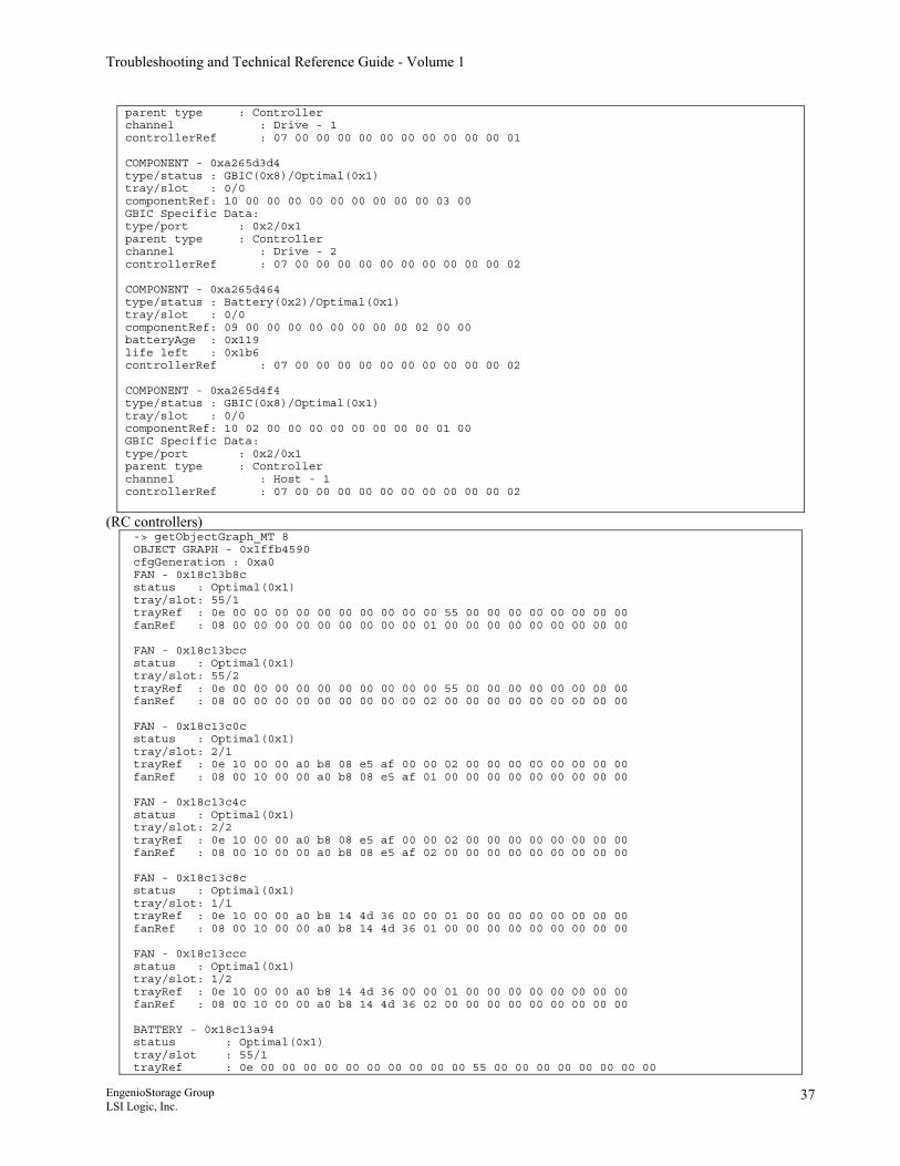
Troubleshooting and Technical Reference Guide - Volume 1
parent type : Controller channel : Drive - 1 controllerRef : 07 00 00 00 00 00 00 00 00 00 00 01 COMPONENT - 0xa265d3d4 type/status : GBIC(0x8)/Optimal(0x1) tray/slot : 0/0 componentRef: 10 00 00 00 00 00 00 00 00 00 03 00 GBIC Specific Data: type/port : 0x2/0x1 parent type : Controller channel : Drive - 2 controllerRef : 07 00 00 00 00 00 00 00 00 00 00 02 COMPONENT - 0xa265d464 type/status : Battery(0x2)/Optimal(0x1) tray/slot : 0/0 componentRef: 09 00 00 00 00 00 00 00 00 02 00 00 batteryAge : 0x119 life left : 0x1b6 controllerRef : 07 00 00 00 00 00 00 00 00 00 00 02 COMPONENT - 0xa265d4f4 type/status : GBIC(0x8)/Optimal(0x1) tray/slot : 0/0 componentRef: 10 02 00 00 00 00 00 00 00 00 01 00 GBIC Specific Data: type/port : 0x2/0x1 parent type : Controller channel : Host - 1 controllerRef : 07 00 00 00 00 00 00 00 00 00 00 02
(RC controllers) -> getObjectGraph_MT 8 OBJECT GRAPH - 0x1ffb4590 cfgGeneration : 0xa0 FAN - 0x18c13b8c status : Optimal(0x1) tray/slot: 55/1 trayRef : 0e 00 00 00 00 00 00 00 00 00 00 55 00 00 00 00 00 00 00 00 fanRef : 08 00 00 00 00 00 00 00 00 00 01 00 00 00 00 00 00 00 00 00 FAN - 0x18c13bcc status : Optimal(0x1) tray/slot: 55/2 trayRef : 0e 00 00 00 00 00 00 00 00 00 00 55 00 00 00 00 00 00 00 00 fanRef : 08 00 00 00 00 00 00 00 00 00 02 00 00 00 00 00 00 00 00 00 FAN - 0x18c13c0c status : Optimal(0x1) tray/slot: 2/1 trayRef : 0e 10 00 00 a0 b8 08 e5 af 00 00 02 00 00 00 00 00 00 00 00 fanRef : 08 00 10 00 00 a0 b8 08 e5 af 01 00 00 00 00 00 00 00 00 00 FAN - 0x18c13c4c status : Optimal(0x1) tray/slot: 2/2 trayRef : 0e 10 00 00 a0 b8 08 e5 af 00 00 02 00 00 00 00 00 00 00 00 fanRef : 08 00 10 00 00 a0 b8 08 e5 af 02 00 00 00 00 00 00 00 00 00 FAN - 0x18c13c8c status : Optimal(0x1) tray/slot: 1/1 trayRef : 0e 10 00 00 a0 b8 14 4d 36 00 00 01 00 00 00 00 00 00 00 00 fanRef : 08 00 10 00 00 a0 b8 14 4d 36 01 00 00 00 00 00 00 00 00 00 FAN - 0x18c13ccc status : Optimal(0x1) tray/slot: 1/2 trayRef : 0e 10 00 00 a0 b8 14 4d 36 00 00 01 00 00 00 00 00 00 00 00 fanRef : 08 00 10 00 00 a0 b8 14 4d 36 02 00 00 00 00 00 00 00 00 00 BATTERY - 0x18c13a94 status : Optimal(0x1) tray/slot : 55/1 trayRef : 0e 00 00 00 00 00 00 00 00 00 00 55 00 00 00 00 00 00 00 00
EngenioStorage Group LSI Logic, Inc.
37
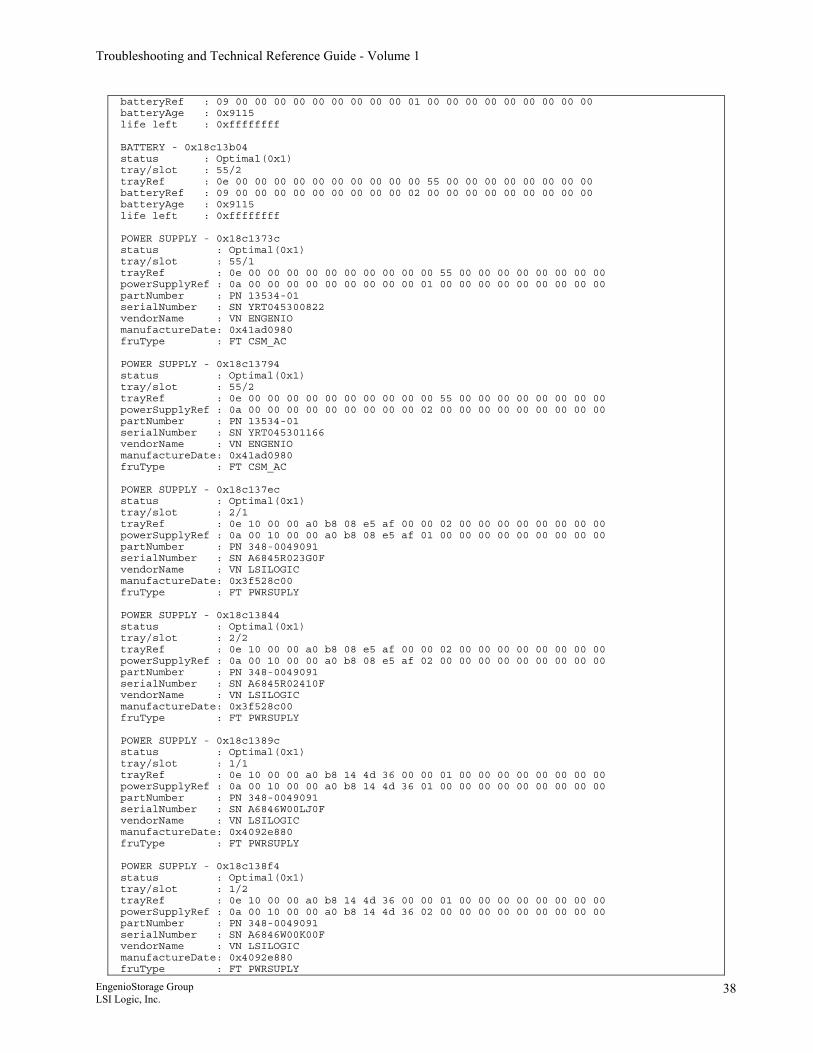
Troubleshooting and Technical Reference Guide - Volume 1
batteryRef : 09 00 00 00 00 00 00 00 00 00 01 00 00 00 00 00 00 00 00 00 batteryAge : 0x9115 life left : 0xffffffff BATTERY - 0x18c13b04 status : Optimal(0x1) tray/slot : 55/2 trayRef : 0e 00 00 00 00 00 00 00 00 00 00 55 00 00 00 00 00 00 00 00 batteryRef : 09 00 00 00 00 00 00 00 00 00 02 00 00 00 00 00 00 00 00 00 batteryAge : 0x9115 life left : 0xffffffff POWER SUPPLY - 0x18c1373c status : Optimal(0x1) tray/slot : 55/1 trayRef : 0e 00 00 00 00 00 00 00 00 00 00 55 00 00 00 00 00 00 00 00 powerSupplyRef : 0a 00 00 00 00 00 00 00 00 00 01 00 00 00 00 00 00 00 00 00 partNumber : PN 13534-01 serialNumber : SN YRT045300822 vendorName : VN ENGENIO manufactureDate: 0x41ad0980 fruType : FT CSM_AC POWER SUPPLY - 0x18c13794 status : Optimal(0x1) tray/slot : 55/2 trayRef : 0e 00 00 00 00 00 00 00 00 00 00 55 00 00 00 00 00 00 00 00 powerSupplyRef : 0a 00 00 00 00 00 00 00 00 00 02 00 00 00 00 00 00 00 00 00 partNumber : PN 13534-01 serialNumber : SN YRT045301166 vendorName : VN ENGENIO manufactureDate: 0x41ad0980 fruType : FT CSM_AC POWER SUPPLY - 0x18c137ec status : Optimal(0x1) tray/slot : 2/1 trayRef : 0e 10 00 00 a0 b8 08 e5 af 00 00 02 00 00 00 00 00 00 00 00 powerSupplyRef : 0a 00 10 00 00 a0 b8 08 e5 af 01 00 00 00 00 00 00 00 00 00 partNumber : PN 348-0049091 serialNumber : SN A6845R023G0F vendorName : VN LSILOGIC manufactureDate: 0x3f528c00 fruType : FT PWRSUPLY POWER SUPPLY - 0x18c13844 status : Optimal(0x1) tray/slot : 2/2 trayRef : 0e 10 00 00 a0 b8 08 e5 af 00 00 02 00 00 00 00 00 00 00 00 powerSupplyRef : 0a 00 10 00 00 a0 b8 08 e5 af 02 00 00 00 00 00 00 00 00 00 partNumber : PN 348-0049091 serialNumber : SN A6845R02410F vendorName : VN LSILOGIC manufactureDate: 0x3f528c00 fruType : FT PWRSUPLY POWER SUPPLY - 0x18c1389c status : Optimal(0x1) tray/slot : 1/1 trayRef : 0e 10 00 00 a0 b8 14 4d 36 00 00 01 00 00 00 00 00 00 00 00 powerSupplyRef : 0a 00 10 00 00 a0 b8 14 4d 36 01 00 00 00 00 00 00 00 00 00 partNumber : PN 348-0049091 serialNumber : SN A6846W00LJ0F vendorName : VN LSILOGIC manufactureDate: 0x4092e880 fruType : FT PWRSUPLY POWER SUPPLY - 0x18c138f4 status : Optimal(0x1) tray/slot : 1/2 trayRef : 0e 10 00 00 a0 b8 14 4d 36 00 00 01 00 00 00 00 00 00 00 00 powerSupplyRef : 0a 00 10 00 00 a0 b8 14 4d 36 02 00 00 00 00 00 00 00 00 00 partNumber : PN 348-0049091 serialNumber : SN A6846W00K00F vendorName : VN LSILOGIC manufactureDate: 0x4092e880 fruType : FT PWRSUPLY
EngenioStorage Group LSI Logic, Inc.
38
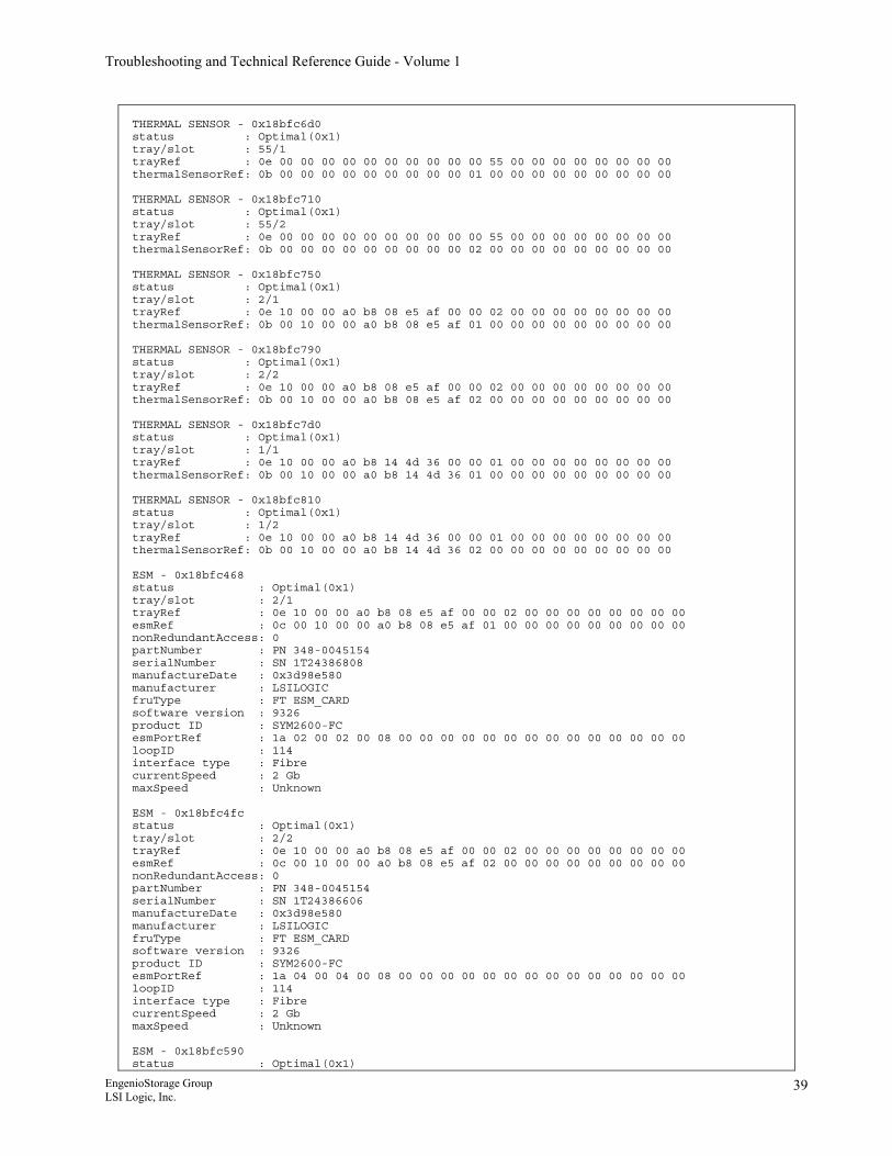
Troubleshooting and Technical Reference Guide - Volume 1
THERMAL SENSOR - 0x18bfc6d0 status : Optimal(0x1) tray/slot : 55/1 trayRef : 0e 00 00 00 00 00 00 00 00 00 00 55 00 00 00 00 00 00 00 00 thermalSensorRef: 0b 00 00 00 00 00 00 00 00 00 01 00 00 00 00 00 00 00 00 00 THERMAL SENSOR - 0x18bfc710 status : Optimal(0x1) tray/slot : 55/2 trayRef : 0e 00 00 00 00 00 00 00 00 00 00 55 00 00 00 00 00 00 00 00 thermalSensorRef: 0b 00 00 00 00 00 00 00 00 00 02 00 00 00 00 00 00 00 00 00 THERMAL SENSOR - 0x18bfc750 status : Optimal(0x1) tray/slot : 2/1 trayRef : 0e 10 00 00 a0 b8 08 e5 af 00 00 02 00 00 00 00 00 00 00 00 thermalSensorRef: 0b 00 10 00 00 a0 b8 08 e5 af 01 00 00 00 00 00 00 00 00 00 THERMAL SENSOR - 0x18bfc790 status : Optimal(0x1) tray/slot : 2/2 trayRef : 0e 10 00 00 a0 b8 08 e5 af 00 00 02 00 00 00 00 00 00 00 00 thermalSensorRef: 0b 00 10 00 00 a0 b8 08 e5 af 02 00 00 00 00 00 00 00 00 00 THERMAL SENSOR - 0x18bfc7d0 status : Optimal(0x1) tray/slot : 1/1 trayRef : 0e 10 00 00 a0 b8 14 4d 36 00 00 01 00 00 00 00 00 00 00 00 thermalSensorRef: 0b 00 10 00 00 a0 b8 14 4d 36 01 00 00 00 00 00 00 00 00 00 THERMAL SENSOR - 0x18bfc810 status : Optimal(0x1) tray/slot : 1/2 trayRef : 0e 10 00 00 a0 b8 14 4d 36 00 00 01 00 00 00 00 00 00 00 00 thermalSensorRef: 0b 00 10 00 00 a0 b8 14 4d 36 02 00 00 00 00 00 00 00 00 00 ESM - 0x18bfc468 status : Optimal(0x1) tray/slot : 2/1 trayRef : 0e 10 00 00 a0 b8 08 e5 af 00 00 02 00 00 00 00 00 00 00 00 esmRef : 0c 00 10 00 00 a0 b8 08 e5 af 01 00 00 00 00 00 00 00 00 00 nonRedundantAccess: 0 partNumber : PN 348-0045154 serialNumber : SN 1T24386808 manufactureDate : 0x3d98e580 manufacturer : LSILOGIC fruType : FT ESM_CARD software version : 9326 product ID : SYM2600-FC esmPortRef : 1a 02 00 02 00 08 00 00 00 00 00 00 00 00 00 00 00 00 00 00 loopID : 114 interface type : Fibre currentSpeed : 2 Gb maxSpeed : Unknown ESM - 0x18bfc4fc status : Optimal(0x1) tray/slot : 2/2 trayRef : 0e 10 00 00 a0 b8 08 e5 af 00 00 02 00 00 00 00 00 00 00 00 esmRef : 0c 00 10 00 00 a0 b8 08 e5 af 02 00 00 00 00 00 00 00 00 00 nonRedundantAccess: 0 partNumber : PN 348-0045154 serialNumber : SN 1T24386606 manufactureDate : 0x3d98e580 manufacturer : LSILOGIC fruType : FT ESM_CARD software version : 9326 product ID : SYM2600-FC esmPortRef : 1a 04 00 04 00 08 00 00 00 00 00 00 00 00 00 00 00 00 00 00 loopID : 114 interface type : Fibre currentSpeed : 2 Gb maxSpeed : Unknown ESM - 0x18bfc590 status : Optimal(0x1)
EngenioStorage Group LSI Logic, Inc.
39
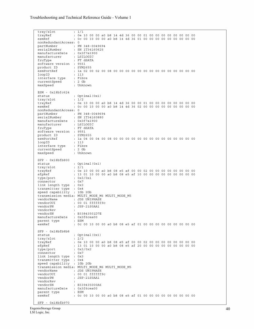
Troubleshooting and Technical Reference Guide - Volume 1
tray/slot : 1/1 trayRef : 0e 10 00 00 a0 b8 14 4d 36 00 00 01 00 00 00 00 00 00 00 00 esmRef : 0c 00 10 00 00 a0 b8 14 4d 36 01 00 00 00 00 00 00 00 00 00 nonRedundantAccess: 0 partNumber : PN 348-0049694 serialNumber : SN 1T34160625 manufactureDate : 0x3f7a1900 manufacturer : LSILOGIC fruType : FT dSATA software version : 9551 product ID : SYM2655 esmPortRef : 1a 02 00 02 00 08 00 00 00 00 00 00 00 00 00 00 00 00 00 00 loopID : 113 interface type : Fibre currentSpeed : 2 Gb maxSpeed : Unknown ESM - 0x18bfc624 status : Optimal(0x1) tray/slot : 1/2 trayRef : 0e 10 00 00 a0 b8 14 4d 36 00 00 01 00 00 00 00 00 00 00 00 esmRef : 0c 00 10 00 00 a0 b8 14 4d 36 02 00 00 00 00 00 00 00 00 00 nonRedundantAccess: 0 partNumber : PN 348-0049694 serialNumber : SN 1T34160880 manufactureDate : 0x3f7a1900 manufacturer : LSILOGIC fruType : FT dSATA software version : 9551 product ID : SYM2655 esmPortRef : 1a 04 00 04 00 08 00 00 00 00 00 00 00 00 00 00 00 00 00 00 loopID : 113 interface type : Fibre currentSpeed : 2 Gb maxSpeed : Unknown SFP - 0x18bfb800 status : Optimal(0x1) tray/slot : 2/1 trayRef : 0e 10 00 00 a0 b8 08 e5 af 00 00 02 00 00 00 00 00 00 00 00 sfpRef : 13 01 10 00 00 a0 b8 08 e5 af 10 00 00 00 00 00 00 00 00 00 type/port : 0x3/0x1 connector : 0x7 link length type : 0x3 transmitter type : 0x4 speed capability : 1Gb 2Gb transmission media: MULTI_MODE_M6 MULTI_MODE_M5 vendorName : JDS UNIPHASE vendorOUI : 00 01 ffffff9c vendorPN : JSP-21S0AA1 vendorRev : vendorSN : B33843501D7E manufactureDate : 0x3f6cea00 parent type : ESM esmRef : 0c 00 10 00 00 a0 b8 08 e5 af 01 00 00 00 00 00 00 00 00 00 SFP - 0x18bfb8b8 status : Optimal(0x1) tray/slot : 2/2 trayRef : 0e 10 00 00 a0 b8 08 e5 af 00 00 02 00 00 00 00 00 00 00 00 sfpRef : 13 01 10 00 00 a0 b8 08 e5 af 20 00 00 00 00 00 00 00 00 00 type/port : 0x3/0x2 connector : 0x7 link length type : 0x3 transmitter type : 0x4 speed capability : 1Gb 2Gb transmission media: MULTI_MODE_M6 MULTI_MODE_M5 vendorName : JDS UNIPHASE vendorOUI : 00 01 ffffff9c vendorPN : JSP-21S0AA1 vendorRev : vendorSN : B339435000A6 manufactureDate : 0x3f6cea00 parent type : ESM esmRef : 0c 00 10 00 00 a0 b8 08 e5 af 01 00 00 00 00 00 00 00 00 00 SFP - 0x18bfb970
EngenioStorage Group LSI Logic, Inc.
40
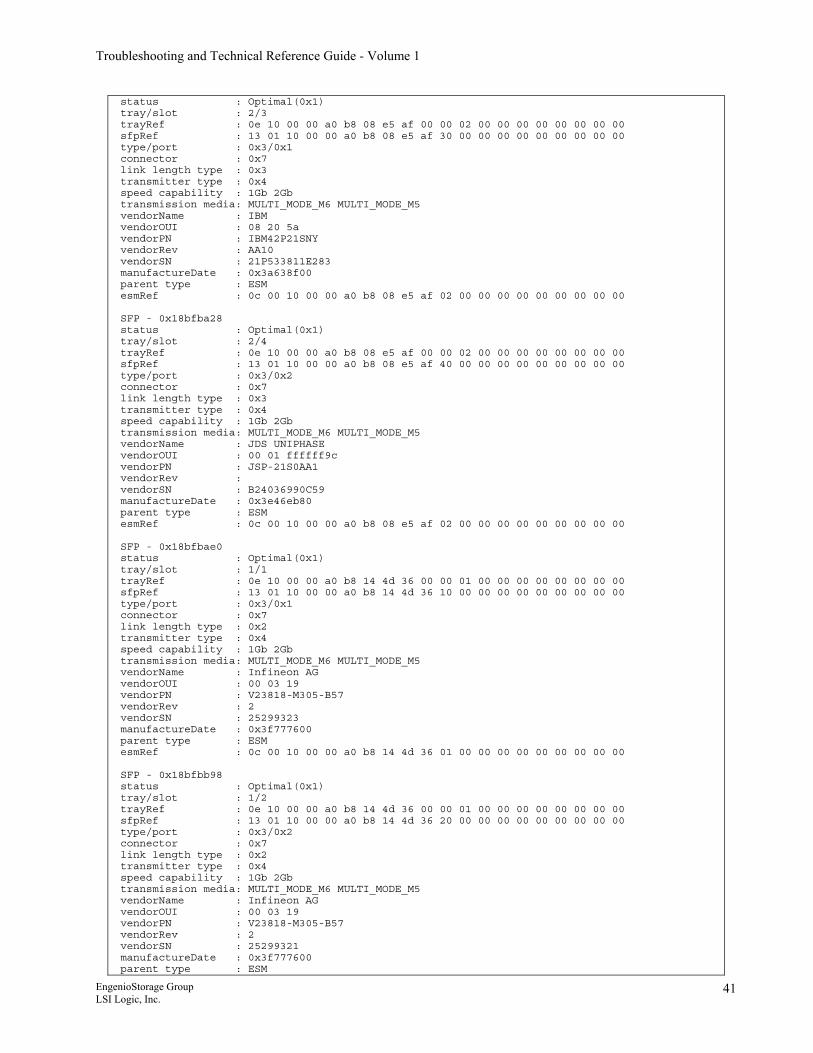
Troubleshooting and Technical Reference Guide - Volume 1
status : Optimal(0x1) tray/slot : 2/3 trayRef : 0e 10 00 00 a0 b8 08 e5 af 00 00 02 00 00 00 00 00 00 00 00 sfpRef : 13 01 10 00 00 a0 b8 08 e5 af 30 00 00 00 00 00 00 00 00 00 type/port : 0x3/0x1 connector : 0x7 link length type : 0x3 transmitter type : 0x4 speed capability : 1Gb 2Gb transmission media: MULTI_MODE_M6 MULTI_MODE_M5 vendorName : IBM vendorOUI : 08 20 5a vendorPN : IBM42P21SNY vendorRev : AA10 vendorSN : 21P533811E283 manufactureDate : 0x3a638f00 parent type : ESM esmRef : 0c 00 10 00 00 a0 b8 08 e5 af 02 00 00 00 00 00 00 00 00 00 SFP - 0x18bfba28 status : Optimal(0x1) tray/slot : 2/4 trayRef : 0e 10 00 00 a0 b8 08 e5 af 00 00 02 00 00 00 00 00 00 00 00 sfpRef : 13 01 10 00 00 a0 b8 08 e5 af 40 00 00 00 00 00 00 00 00 00 type/port : 0x3/0x2 connector : 0x7 link length type : 0x3 transmitter type : 0x4 speed capability : 1Gb 2Gb transmission media: MULTI_MODE_M6 MULTI_MODE_M5 vendorName : JDS UNIPHASE vendorOUI : 00 01 ffffff9c vendorPN : JSP-21S0AA1 vendorRev : vendorSN : B24036990C59 manufactureDate : 0x3e46eb80 parent type : ESM esmRef : 0c 00 10 00 00 a0 b8 08 e5 af 02 00 00 00 00 00 00 00 00 00 SFP - 0x18bfbae0 status : Optimal(0x1) tray/slot : 1/1 trayRef : 0e 10 00 00 a0 b8 14 4d 36 00 00 01 00 00 00 00 00 00 00 00 sfpRef : 13 01 10 00 00 a0 b8 14 4d 36 10 00 00 00 00 00 00 00 00 00 type/port : 0x3/0x1 connector : 0x7 link length type : 0x2 transmitter type : 0x4 speed capability : 1Gb 2Gb transmission media: MULTI_MODE_M6 MULTI_MODE_M5 vendorName : Infineon AG vendorOUI : 00 03 19 vendorPN : V23818-M305-B57 vendorRev : 2 vendorSN : 25299323 manufactureDate : 0x3f777600 parent type : ESM esmRef : 0c 00 10 00 00 a0 b8 14 4d 36 01 00 00 00 00 00 00 00 00 00 SFP - 0x18bfbb98 status : Optimal(0x1) tray/slot : 1/2 trayRef : 0e 10 00 00 a0 b8 14 4d 36 00 00 01 00 00 00 00 00 00 00 00 sfpRef : 13 01 10 00 00 a0 b8 14 4d 36 20 00 00 00 00 00 00 00 00 00 type/port : 0x3/0x2 connector : 0x7 link length type : 0x2 transmitter type : 0x4 speed capability : 1Gb 2Gb transmission media: MULTI_MODE_M6 MULTI_MODE_M5 vendorName : Infineon AG vendorOUI : 00 03 19 vendorPN : V23818-M305-B57 vendorRev : 2 vendorSN : 25299321 manufactureDate : 0x3f777600 parent type : ESM
EngenioStorage Group LSI Logic, Inc.
41
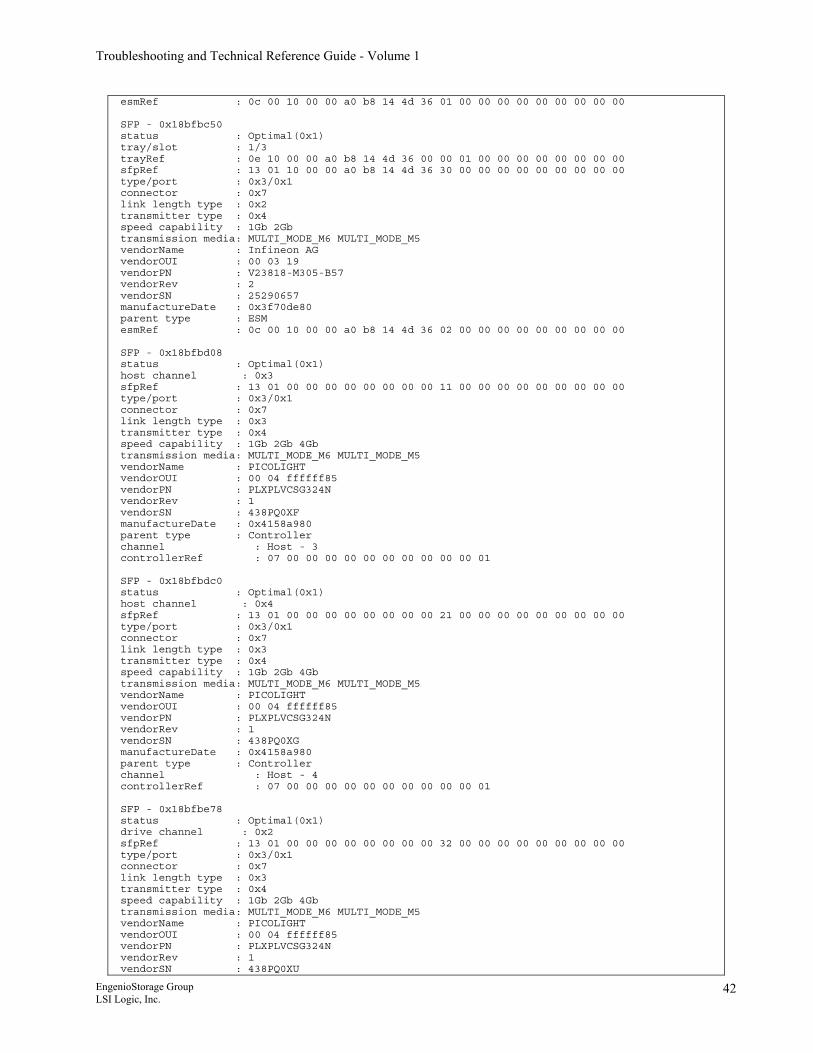
Troubleshooting and Technical Reference Guide - Volume 1
esmRef : 0c 00 10 00 00 a0 b8 14 4d 36 01 00 00 00 00 00 00 00 00 00 SFP - 0x18bfbc50 status : Optimal(0x1) tray/slot : 1/3 trayRef : 0e 10 00 00 a0 b8 14 4d 36 00 00 01 00 00 00 00 00 00 00 00 sfpRef : 13 01 10 00 00 a0 b8 14 4d 36 30 00 00 00 00 00 00 00 00 00 type/port : 0x3/0x1 connector : 0x7 link length type : 0x2 transmitter type : 0x4 speed capability : 1Gb 2Gb transmission media: MULTI_MODE_M6 MULTI_MODE_M5 vendorName : Infineon AG vendorOUI : 00 03 19 vendorPN : V23818-M305-B57 vendorRev : 2 vendorSN : 25290657 manufactureDate : 0x3f70de80 parent type : ESM esmRef : 0c 00 10 00 00 a0 b8 14 4d 36 02 00 00 00 00 00 00 00 00 00 SFP - 0x18bfbd08 status : Optimal(0x1) host channel : 0x3 sfpRef : 13 01 00 00 00 00 00 00 00 00 11 00 00 00 00 00 00 00 00 00 type/port : 0x3/0x1 connector : 0x7 link length type : 0x3 transmitter type : 0x4 speed capability : 1Gb 2Gb 4Gb transmission media: MULTI_MODE_M6 MULTI_MODE_M5 vendorName : PICOLIGHT vendorOUI : 00 04 ffffff85 vendorPN : PLXPLVCSG324N vendorRev : 1 vendorSN : 438PQ0XF manufactureDate : 0x4158a980 parent type : Controller channel : Host - 3 controllerRef : 07 00 00 00 00 00 00 00 00 00 00 01 SFP - 0x18bfbdc0 status : Optimal(0x1) host channel : 0x4 sfpRef : 13 01 00 00 00 00 00 00 00 00 21 00 00 00 00 00 00 00 00 00 type/port : 0x3/0x1 connector : 0x7 link length type : 0x3 transmitter type : 0x4 speed capability : 1Gb 2Gb 4Gb transmission media: MULTI_MODE_M6 MULTI_MODE_M5 vendorName : PICOLIGHT vendorOUI : 00 04 ffffff85 vendorPN : PLXPLVCSG324N vendorRev : 1 vendorSN : 438PQ0XG manufactureDate : 0x4158a980 parent type : Controller channel : Host - 4 controllerRef : 07 00 00 00 00 00 00 00 00 00 00 01 SFP - 0x18bfbe78 status : Optimal(0x1) drive channel : 0x2 sfpRef : 13 01 00 00 00 00 00 00 00 00 32 00 00 00 00 00 00 00 00 00 type/port : 0x3/0x1 connector : 0x7 link length type : 0x3 transmitter type : 0x4 speed capability : 1Gb 2Gb 4Gb transmission media: MULTI_MODE_M6 MULTI_MODE_M5 vendorName : PICOLIGHT vendorOUI : 00 04 ffffff85 vendorPN : PLXPLVCSG324N vendorRev : 1 vendorSN : 438PQ0XU
EngenioStorage Group LSI Logic, Inc.
42
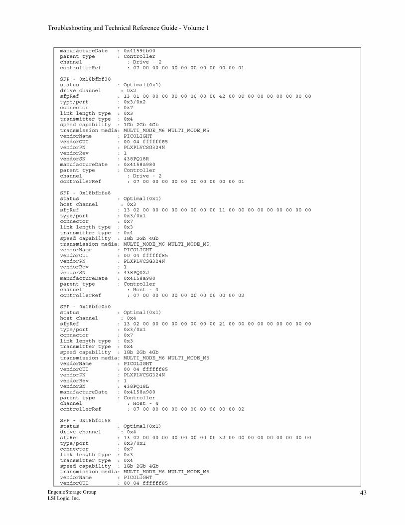
Troubleshooting and Technical Reference Guide - Volume 1
manufactureDate : 0x4159fb00 parent type : Controller channel : Drive - 2 controllerRef : 07 00 00 00 00 00 00 00 00 00 00 01 SFP - 0x18bfbf30 status : Optimal(0x1) drive channel : 0x2 sfpRef : 13 01 00 00 00 00 00 00 00 00 42 00 00 00 00 00 00 00 00 00 type/port : 0x3/0x2 connector : 0x7 link length type : 0x3 transmitter type : 0x4 speed capability : 1Gb 2Gb 4Gb transmission media: MULTI_MODE_M6 MULTI_MODE_M5 vendorName : PICOLIGHT vendorOUI : 00 04 ffffff85 vendorPN : PLXPLVCSG324N vendorRev : 1 vendorSN : 438PQ18R manufactureDate : 0x4158a980 parent type : Controller channel : Drive - 2 controllerRef : 07 00 00 00 00 00 00 00 00 00 00 01 SFP - 0x18bfbfe8 status : Optimal(0x1) host channel : 0x3 sfpRef : 13 02 00 00 00 00 00 00 00 00 11 00 00 00 00 00 00 00 00 00 type/port : 0x3/0x1 connector : 0x7 link length type : 0x3 transmitter type : 0x4 speed capability : 1Gb 2Gb 4Gb transmission media: MULTI_MODE_M6 MULTI_MODE_M5 vendorName : PICOLIGHT vendorOUI : 00 04 ffffff85 vendorPN : PLXPLVCSG324N vendorRev : 1 vendorSN : 438PQ0XJ manufactureDate : 0x4158a980 parent type : Controller channel : Host - 3 controllerRef : 07 00 00 00 00 00 00 00 00 00 00 02 SFP - 0x18bfc0a0 status : Optimal(0x1) host channel : 0x4 sfpRef : 13 02 00 00 00 00 00 00 00 00 21 00 00 00 00 00 00 00 00 00 type/port : 0x3/0x1 connector : 0x7 link length type : 0x3 transmitter type : 0x4 speed capability : 1Gb 2Gb 4Gb transmission media: MULTI_MODE_M6 MULTI_MODE_M5 vendorName : PICOLIGHT vendorOUI : 00 04 ffffff85 vendorPN : PLXPLVCSG324N vendorRev : 1 vendorSN : 438PQ18L manufactureDate : 0x4158a980 parent type : Controller channel : Host - 4 controllerRef : 07 00 00 00 00 00 00 00 00 00 00 02 SFP - 0x18bfc158 status : Optimal(0x1) drive channel : 0x4 sfpRef : 13 02 00 00 00 00 00 00 00 00 32 00 00 00 00 00 00 00 00 00 type/port : 0x3/0x1 connector : 0x7 link length type : 0x3 transmitter type : 0x4 speed capability : 1Gb 2Gb 4Gb transmission media: MULTI_MODE_M6 MULTI_MODE_M5 vendorName : PICOLIGHT vendorOUI : 00 04 ffffff85
EngenioStorage Group LSI Logic, Inc.
43
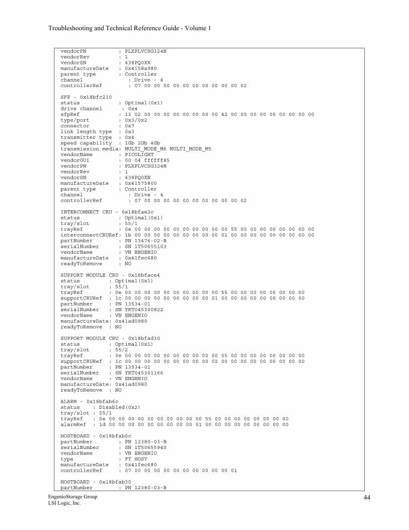
Troubleshooting and Technical Reference Guide - Volume 1
vendorPN : PLXPLVCSG324N vendorRev : 1 vendorSN : 438PQ0XK manufactureDate : 0x4158a980 parent type : Controller channel : Drive - 4 controllerRef : 07 00 00 00 00 00 00 00 00 00 00 02 SFP - 0x18bfc210 status : Optimal(0x1) drive channel : 0x4 sfpRef : 13 02 00 00 00 00 00 00 00 00 42 00 00 00 00 00 00 00 00 00 type/port : 0x3/0x2 connector : 0x7 link length type : 0x3 transmitter type : 0x4 speed capability : 1Gb 2Gb 4Gb transmission media: MULTI_MODE_M6 MULTI_MODE_M5 vendorName : PICOLIGHT vendorOUI : 00 04 ffffff85 vendorPN : PLXPLVCSG324N vendorRev : 1 vendorSN : 438PQ0XN manufactureDate : 0x41575800 parent type : Controller channel : Drive - 4 controllerRef : 07 00 00 00 00 00 00 00 00 00 00 02 INTERCONNECT CRU - 0x18bfae2c status : Optimal(0x1) tray/slot : 55/1 trayRef : 0e 00 00 00 00 00 00 00 00 00 00 55 00 00 00 00 00 00 00 00 interconnectCRURef: 1b 00 00 00 00 00 00 00 00 00 01 00 00 00 00 00 00 00 00 00 partNumber : PN 13476-02-B serialNumber : SN 1T50655103 vendorName : VN ENGENIO manufactureDate : 0x41fec680 readyToRemove : NO SUPPORT MODULE CRU - 0x18bface4 status : Optimal(0x1) tray/slot : 55/1 trayRef : 0e 00 00 00 00 00 00 00 00 00 00 55 00 00 00 00 00 00 00 00 supportCRURef : 1c 00 00 00 00 00 00 00 00 00 01 00 00 00 00 00 00 00 00 00 partNumber : PN 13534-01 serialNumber : SN YRT045300822 vendorName : VN ENGENIO manufactureDate: 0x41ad0980 readyToRemove : NO SUPPORT MODULE CRU - 0x18bfad30 status : Optimal(0x1) tray/slot : 55/2 trayRef : 0e 00 00 00 00 00 00 00 00 00 00 55 00 00 00 00 00 00 00 00 supportCRURef : 1c 00 00 00 00 00 00 00 00 00 02 00 00 00 00 00 00 00 00 00 partNumber : PN 13534-01 serialNumber : SN YRT045301166 vendorName : VN ENGENIO manufactureDate: 0x41ad0980 readyToRemove : NO ALARM - 0x18bfab6c status : Disabled(0x2) tray/slot : 55/1 trayRef : 0e 00 00 00 00 00 00 00 00 00 00 55 00 00 00 00 00 00 00 00 alarmRef : 1d 00 00 00 00 00 00 00 00 00 01 00 00 00 00 00 00 00 00 00 HOSTBOARD - 0x18bfab0c partNumber : PN 12380-03-B serialNumber : SN 1T50655940 vendorName : VN ENGENIO type : FT HOST manufactureDate : 0x41fec680 controllerRef : 07 00 00 00 00 00 00 00 00 00 00 01 HOSTBOARD - 0x18bfab30 partNumber : PN 12380-03-B
EngenioStorage Group LSI Logic, Inc.
44
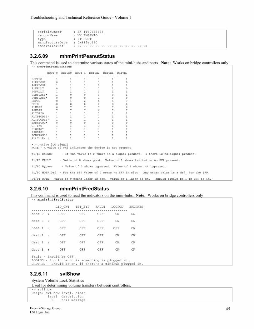
Troubleshooting and Technical Reference Guide - Volume 1
serialNumber : SN 1T50655698 vendorName : VN ENGENIO type : FT HOST manufactureDate : 0x41fec680 controllerRef : 07 00 00 00 00 00 00 00 00 00 00 02
3.2.6.09 mhmPrintPeanutStatus This command is used to determine various states of the mini-hubs and ports. Note: Works on bridge controllers only -> mhmPrintPeanutStatus HOST 0 DRIVE0 HOST 1 DRIVE2 DRIVE1 DRIVE3 ------------------------------------------------------- LIPREQ 1 1 1 1 1 1 P1RXLOSS 0 1 1 1 1 0 P0RXLOSS 1 1 1 0 1 1 P1FAULT 0 1 1 1 1 0 P0FAULT 1 1 1 0 1 1 P1BYPASS* 1 0 0 0 0 1 P0BYPASS* 0 0 0 1 0 0 BDPOS 0 4 2 6 5 7 BDID 0 0 0 0 0 0 P1MDEF 6 7 7 7 7 6 P0MDEF 7 7 7 6 7 7 ALTGPIO 1 1 1 1 1 1 ALTP1ODIS* 1 1 1 1 1 1 ALTP0ODIS* 1 1 1 1 1 1 BRDRECOG* 0 0 0 0 0 0 GP I/O 1 1 1 1 1 1 P1ODIS* 1 1 1 1 1 1 P0ODIS* 1 1 1 1 1 1 FCBYPASS* 1 1 1 1 1 1 AltCtlRst* 1 1 1 1 1 1 * - Active low signal NOTE - A value of 0xf indicates the device is not present. p1/p0 RXLOSS - If the value is 0 there is a signal present. 1 there is no signal present. P1/P0 FAULT - Value of 0 shows good. Value of 1 shows faulted or no SFP present. P1/P0 Bypass - Value of 0 shows bypassed. Value of 1 shows not bypassed. P1/P0 MDEF Def. - For the SFP Value of 7 means no SFP in slot. Any other value is a def. For the SFP. P0/P1 ODIS - Value of 0 means laser is off. Value of 1 laser is on. ( should always be 1 in SFP is in.)
3.2.6.10 mhmPrintFredStatus This command is used to read the indicators on the mini-hubs. Note: Works on bridge controllers only -> mhmPrintFredStatus LIP_GNT TST_BYP FAULT LOOPGD BRDPRES ------------------------------------------------ host 0 : OFF OFF OFF ON ON dest 0 : OFF OFF OFF ON ON host 1 : OFF OFF OFF OFF ON dest 2 : OFF OFF OFF ON ON dest 1 : OFF OFF OFF ON ON dest 3 : OFF OFF OFF ON ON Fault - Should be OFF LOOPGD - Should be on is something is plugged in. BRDPRES - Should be on, if there’s a minihub plugged in.
3.2.6.11 svlShow System Volume Lock Statistics Used for determining volume transfers between controllers. -> svlShow Usage: svlShow level, clear level description 0 this message
EngenioStorage Group LSI Logic, Inc.
45
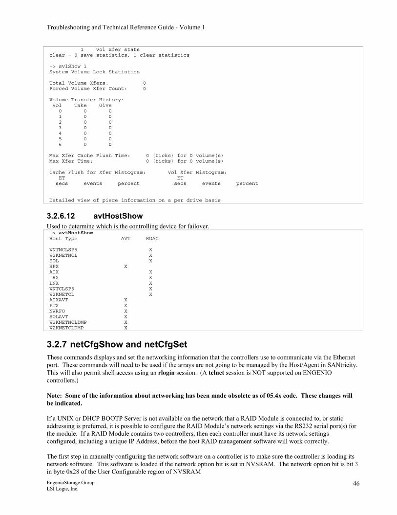
Troubleshooting and Technical Reference Guide - Volume 1
1 vol xfer stats clear = 0 save statistics, 1 clear statistics -> svlShow 1 System Volume Lock Statistics Total Volume Xfers: 0 Forced Volume Xfer Count: 0 Volume Transfer History: Vol Take Give 0 0 0 1 0 0 2 0 0 3 0 0 4 0 0 5 0 0 6 0 0 Max Xfer Cache Flush Time: 0 (ticks) for 0 volume(s) Max Xfer Time: 0 (ticks) for 0 volume(s) Cache Flush for Xfer Histogram: Vol Xfer Histogram: ET ET secs events percent secs events percent Detailed view of piece information on a per drive basis
3.2.6.12 avtHostShow Used to determine which is the controlling device for failover. -> avtHostShow Host Type AVT RDAC WNTNCLSP5 X W2KNETNCL X SOL X HPX X AIX X IRX X LNX X WNTCLSP5 X W2KNETCL X AIXAVT X PTX X NWRFO X SOLAVT X W2KNETNCLDMP X W2KNETCLDMP X
3.2.7 netCfgShow and netCfgSet These commands displays and set the networking information that the controllers use to communicate via the Ethernet port. These commands will need to be used if the arrays are not going to be managed by the Host/Agent in SANtricity. This will also permit shell access using an rlogin session. (A telnet session is NOT supported on ENGENIO controllers.) Note: Some of the information about networking has been made obsolete as of 05.4x code. These changes will be indicated. If a UNIX or DHCP BOOTP Server is not available on the network that a RAID Module is connected to, or static addressing is preferred, it is possible to configure the RAID Module’s network settings via the RS232 serial port(s) for the module. If a RAID Module contains two controllers, then each controller must have its network settings configured, including a unique IP Address, before the host RAID management software will work correctly. The first step in manually configuring the network software on a controller is to make sure the controller is loading its network software. This software is loaded if the network option bit is set in NVSRAM. The network option bit is bit 3 in byte 0x28 of the User Configurable region of NVSRAM EngenioStorage Group LSI Logic, Inc.
46
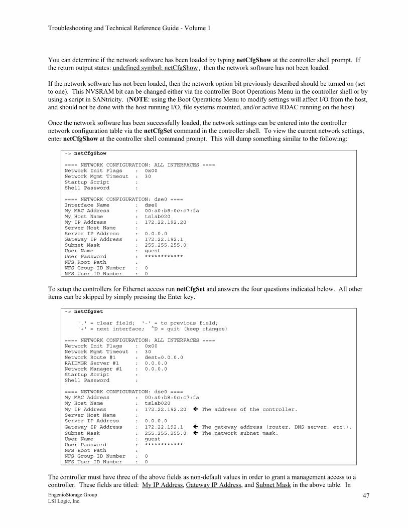
Troubleshooting and Technical Reference Guide - Volume 1
You can determine if the network software has been loaded by typing netCfgShow at the controller shell prompt. If the return output states: undefined symbol: netCfgShow, then the network software has not been loaded. If the network software has not been loaded, then the network option bit previously described should be turned on (set to one). This NVSRAM bit can be changed either via the controller Boot Operations Menu in the controller shell or by using a script in SANtricity. (NOTE: using the Boot Operations Menu to modify settings will affect I/O from the host, and should not be done with the host running I/O, file systems mounted, and/or active RDAC running on the host) Once the network software has been successfully loaded, the network settings can be entered into the controller network configuration table via the netCfgSet command in the controller shell. To view the current network settings, enter netCfgShow at the controller shell command prompt. This will dump something similar to the following:
-> netCfgShow ==== NETWORK CONFIGURATION: ALL INTERFACES ==== Network Init Flags : 0x00 Network Mgmt Timeout : 30 Startup Script : Shell Password : ==== NETWORK CONFIGURATION: dse0 ==== Interface Name : dse0 My MAC Address : 00:a0:b8:0c:c7:fa My Host Name : tslab020 My IP Address : 172.22.192.20 Server Host Name : Server IP Address : 0.0.0.0 Gateway IP Address : 172.22.192.1 Subnet Mask : 255.255.255.0 User Name : guest User Password : ************ NFS Root Path : NFS Group ID Number : 0 NFS User ID Number : 0
To setup the controllers for Ethernet access run netCfgSet and answers the four questions indicated below. All other items can be skipped by simply pressing the Enter key.
-> netCfgSet '.' = clear field; '-' = to previous field; '+' = next interface; ^D = quit (keep changes) ==== NETWORK CONFIGURATION: ALL INTERFACES ==== Network Init Flags : 0x00 Network Mgmt Timeout : 30 Network Route #1 : dest=0.0.0.0 RAIDMGR Server #1 : 0.0.0.0 Network Manager #1 : 0.0.0.0 Startup Script : Shell Password : ==== NETWORK CONFIGURATION: dse0 ==== My MAC Address : 00:a0:b8:0c:c7:fa My Host Name : tslab020 My IP Address : 172.22.192.20 The address of the controller. Server Host Name : Server IP Address : 0.0.0.0 Gateway IP Address : 172.22.192.1 The gateway address (router, DNS server, etc.). Subnet Mask : 255.255.255.0 The network subnet mask. User Name : guest User Password : ************ NFS Root Path : NFS Group ID Number : 0 NFS User ID Number : 0
The controller must have three of the above fields as non-default values in order to grant a management access to a controller. These fields are titled: My IP Address, Gateway IP Address, and Subnet Mask in the above table. In EngenioStorage Group LSI Logic, Inc.
47
Troubleshooting and Technical Reference Guide - Volume 1
addition, some functional requirements require that the Network Init Flags be modified once a module has been successfully added to a RAID management station. For this reason, a table is included in the troubleshooting section of this document that lists those flags an end user might need to alter. Descriptions of the three required fields are given below: My IP Address This field should contain the static IP Address that has been reserved on the network for the controller. Each controller in a dual controller RAID Module must have a unique static IP address reserved for it on the network. Gateway IP Address This field should contain the IP Address of the gateway for the subnetwork to which the RAID Module is connected. If there is no gateway on the subnetwork, e.g., a standalone network is being used or the RAID Manager Server is connected directly to the module via a crossover cable, then use the IP Address of the RAID Manager station in this field. This field cannot be left zeroed out or the network software may not work correctly. Subnet Mask This field should contain the subnet mask of the subnetwork to which the RAID Module is connected. The values in the fields shown above can be modified via the netCfgSet command. This command will display each field listed in the netCfgShow output shown above, one field at a time. When each field is displayed, the cursor will be placed to the right of the current value waiting for user input. Entering a ‘Carriage Return’ at the cursor will cause the current field to be skipped with no changes being made to its value. Entering a period (.) at the prompt will cause the value of the current field to be reset to the factory default. A hyphen (-) in a field displays the previous parameter, an asterisk (*) in a field causes the default value to be used (which may be null), a plus (+) sign causes the set operation to skip to the next interface, and a control-D causes the function to terminate. Finally, to change the value of a field, simply enter the new value at the cursor. IT IS STRONGLY RECOMMENDED that during an initial configuration that all values be set to their default values using an ‘*’, except for the three required settings described in the preceding paragraph. After the netCfgSet command has exited, a message should be displayed which states:
Network Configuration successfully written to NVSRAM. Reboot to use these changes.
The controller should now be rebooted by entering sysReboot at the controller shell prompt (NOTE: this command will affect I/O from the host, and should not be done with the host running I/O, file systems mounted, and/or RDAC actively running on the host). After the controller has finished its boot process, it should be able to ping the IP address of a RAID Manager station. The troubleshooting section of this document contains more detailed information on how to use the ping command in the controller shell. When the ping command is running successfully, perform the previous steps on the other controller if the RAID Module contains dual controllers. Otherwise, refer to the section on troubleshooting in this document. Network Init Flags The Network Init Flags are used to control the initialization of the network interfaces of a controller. The one-byte field displayed next to the Network Init Flags title when the netCfgSet command is run, can be used to modify these flags. Each bit in this one-byte field corresponds to a flag. The function of each of these flags is listed below:
bit 0 =1: Do not use BOOTP for any reason (Obsolete as of 05.4x) =0: Use BOOTP as needed bit 1 =1: Use BOOTP unconditionally (Obsolete as of 05.4x) =0: Use BOOTP only as necessary bit 2 =0: Start NFS services =1: Do not start NFS services
EngenioStorage Group LSI Logic, Inc.
48
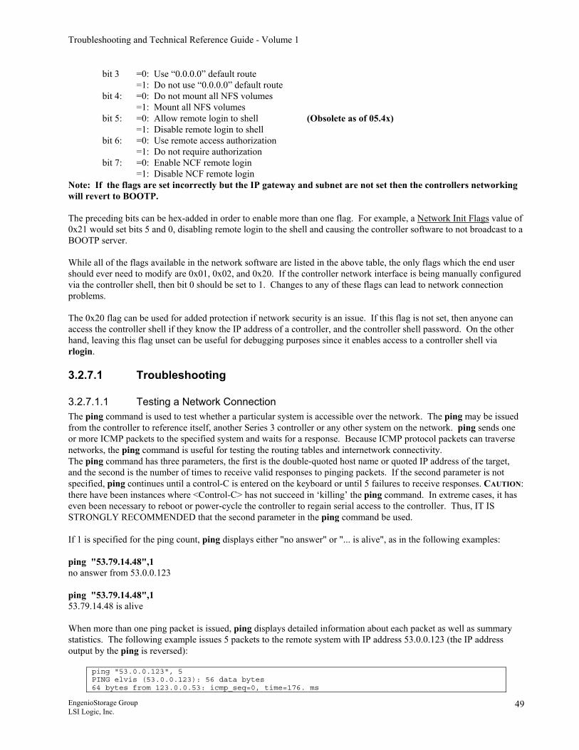
Troubleshooting and Technical Reference Guide - Volume 1
bit 3 =0: Use “0.0.0.0” default route =1: Do not use “0.0.0.0” default route bit 4: =0: Do not mount all NFS volumes =1: Mount all NFS volumes bit 5: =0: Allow remote login to shell (Obsolete as of 05.4x) =1: Disable remote login to shell bit 6: =0: Use remote access authorization =1: Do not require authorization bit 7: =0: Enable NCF remote login =1: Disable NCF remote login
Note: If the flags are set incorrectly but the IP gateway and subnet are not set then the controllers networking will revert to BOOTP. The preceding bits can be hex-added in order to enable more than one flag. For example, a Network Init Flags value of 0x21 would set bits 5 and 0, disabling remote login to the shell and causing the controller software to not broadcast to a BOOTP server. While all of the flags available in the network software are listed in the above table, the only flags which the end user should ever need to modify are 0x01, 0x02, and 0x20. If the controller network interface is being manually configured via the controller shell, then bit 0 should be set to 1. Changes to any of these flags can lead to network connection problems. The 0x20 flag can be used for added protection if network security is an issue. If this flag is not set, then anyone can access the controller shell if they know the IP address of a controller, and the controller shell password. On the other hand, leaving this flag unset can be useful for debugging purposes since it enables access to a controller shell via rlogin.
3.2.7.1 Troubleshooting
3.2.7.1.1 Testing a Network Connection The ping command is used to test whether a particular system is accessible over the network. The ping may be issued from the controller to reference itself, another Series 3 controller or any other system on the network. ping sends one or more ICMP packets to the specified system and waits for a response. Because ICMP protocol packets can traverse networks, the ping command is useful for testing the routing tables and internetwork connectivity. The ping command has three parameters, the first is the double-quoted host name or quoted IP address of the target, and the second is the number of times to receive valid responses to pinging packets. If the second parameter is not specified, ping continues until a control-C is entered on the keyboard or until 5 failures to receive responses. CAUTION: there have been instances where <Control-C> has not succeed in ‘killing’ the ping command. In extreme cases, it has even been necessary to reboot or power-cycle the controller to regain serial access to the controller. Thus, IT IS STRONGLY RECOMMENDED that the second parameter in the ping command be used. If 1 is specified for the ping count, ping displays either "no answer" or "... is alive", as in the following examples: ping "53.79.14.48",1 no answer from 53.0.0.123 ping "53.79.14.48",1 53.79.14.48 is alive When more than one ping packet is issued, ping displays detailed information about each packet as well as summary statistics. The following example issues 5 packets to the remote system with IP address 53.0.0.123 (the IP address output by the ping is reversed):
ping "53.0.0.123", 5 PING elvis (53.0.0.123): 56 data bytes 64 bytes from 123.0.0.53: icmp_seq=0, time=176. ms
EngenioStorage Group LSI Logic, Inc.
49
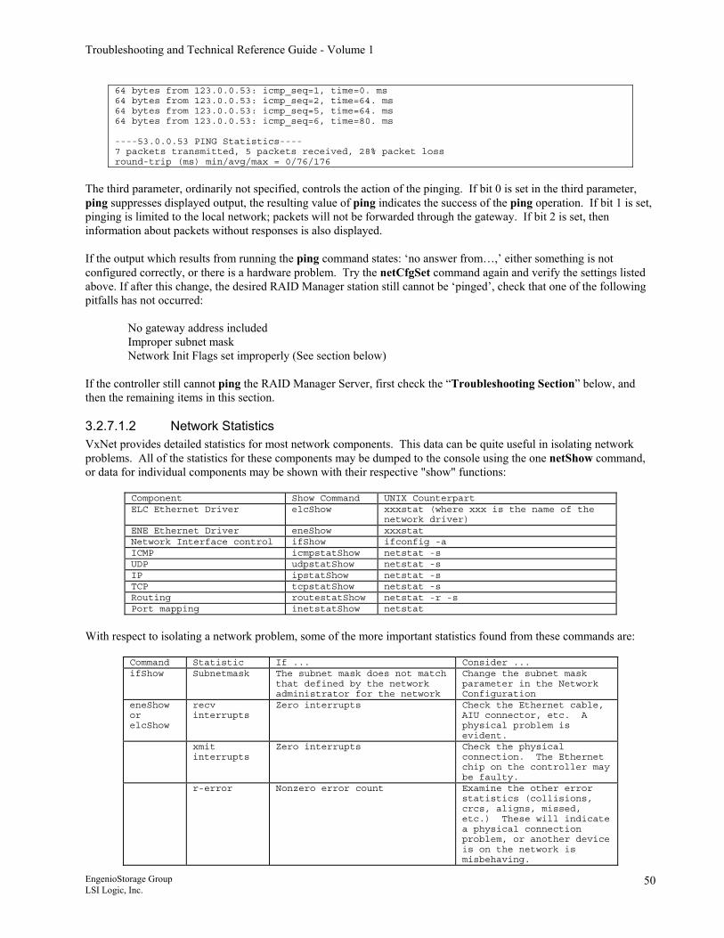
Troubleshooting and Technical Reference Guide - Volume 1
64 bytes from 123.0.0.53: icmp_seq=1, time=0. ms 64 bytes from 123.0.0.53: icmp_seq=2, time=64. ms 64 bytes from 123.0.0.53: icmp_seq=5, time=64. ms 64 bytes from 123.0.0.53: icmp_seq=6, time=80. ms ----53.0.0.53 PING Statistics---- 7 packets transmitted, 5 packets received, 28% packet loss round-trip (ms) min/avg/max = 0/76/176
The third parameter, ordinarily not specified, controls the action of the pinging. If bit 0 is set in the third parameter, ping suppresses displayed output, the resulting value of ping indicates the success of the ping operation. If bit 1 is set, pinging is limited to the local network; packets will not be forwarded through the gateway. If bit 2 is set, then information about packets without responses is also displayed. If the output which results from running the ping command states: ‘no answer from…,’ either something is not configured correctly, or there is a hardware problem. Try the netCfgSet command again and verify the settings listed above. If after this change, the desired RAID Manager station still cannot be ‘pinged’, check that one of the following pitfalls has not occurred:
No gateway address included Improper subnet mask Network Init Flags set improperly (See section below)
If the controller still cannot ping the RAID Manager Server, first check the “Troubleshooting Section” below, and then the remaining items in this section.
3.2.7.1.2 Network Statistics VxNet provides detailed statistics for most network components. This data can be quite useful in isolating network problems. All of the statistics for these components may be dumped to the console using the one netShow command, or data for individual components may be shown with their respective "show" functions:
Component Show Command UNIX Counterpart ELC Ethernet Driver elcShow xxxstat (where xxx is the name of the
network driver) ENE Ethernet Driver eneShow xxxstat Network Interface control ifShow ifconfig -a ICMP icmpstatShow netstat -s UDP udpstatShow netstat -s IP ipstatShow netstat -s TCP tcpstatShow netstat -s Routing routestatShow netstat -r -s Port mapping inetstatShow netstat
With respect to isolating a network problem, some of the more important statistics found from these commands are:
Command Statistic If ... Consider ... ifShow Subnetmask The subnet mask does not match
that defined by the network administrator for the network
Change the subnet mask parameter in the Network Configuration
eneShow or elcShow
recv interrupts
Zero interrupts Check the Ethernet cable, AIU connector, etc. A physical problem is evident.
xmit interrupts
Zero interrupts Check the physical connection. The Ethernet chip on the controller may be faulty.
r-error Nonzero error count Examine the other error statistics (collisions, crcs, aligns, missed, etc.) These will indicate a physical connection problem, or another device is on the network is misbehaving.
EngenioStorage Group LSI Logic, Inc.
50
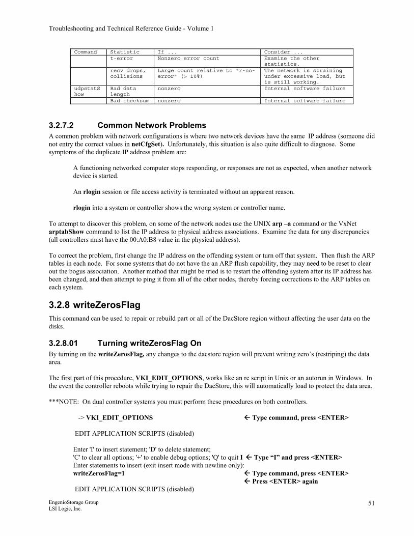
Troubleshooting and Technical Reference Guide - Volume 1
Command Statistic If ... Consider ... t-error Nonzero error count Examine the other
statistics. recv drops,
collisions Large count relative to "r-no-error" (> 10%)
The network is straining under excessive load, but is still working.
udpstatShow
Bad data length
nonzero Internal software failure
Bad checksum nonzero Internal software failure
3.2.7.2 Common Network Problems A common problem with network configurations is where two network devices have the same IP address (someone did not entry the correct values in netCfgSet). Unfortunately, this situation is also quite difficult to diagnose. Some symptoms of the duplicate IP address problem are:
A functioning networked computer stops responding, or responses are not as expected, when another network device is started. An rlogin session or file access activity is terminated without an apparent reason. rlogin into a system or controller shows the wrong system or controller name.
To attempt to discover this problem, on some of the network nodes use the UNIX arp –a command or the VxNet arptabShow command to list the IP address to physical address associations. Examine the data for any discrepancies (all controllers must have the 00:A0:B8 value in the physical address). To correct the problem, first change the IP address on the offending system or turn off that system. Then flush the ARP tables in each node. For some systems that do not have the an ARP flush capability, they may need to be reset to clear out the bogus association. Another method that might be tried is to restart the offending system after its IP address has been changed, and then attempt to ping it from all of the other nodes, thereby forcing corrections to the ARP tables on each system.
3.2.8 writeZerosFlag This command can be used to repair or rebuild part or all of the DacStore region without affecting the user data on the disks.
3.2.8.01 Turning writeZerosFlag On By turning on the writeZerosFlag, any changes to the dacstore region will prevent writing zero’s (restriping) the data area. The first part of this procedure, VKI_EDIT_OPTIONS, works like an rc script in Unix or an autorun in Windows. In the event the controller reboots while trying to repair the DacStore, this will automatically load to protect the data area. ***NOTE: On dual controller systems you must perform these procedures on both controllers.
-> VKI_EDIT_OPTIONS Type command, press <ENTER> EDIT APPLICATION SCRIPTS (disabled) Enter 'I' to insert statement; 'D' to delete statement; 'C' to clear all options; '+' to enable debug options; 'Q' to quit I Type “I” and press <ENTER> Enter statements to insert (exit insert mode with newline only): writeZerosFlag=1 Type command, press <ENTER> Press <ENTER> again EDIT APPLICATION SCRIPTS (disabled)
EngenioStorage Group LSI Logic, Inc.
51
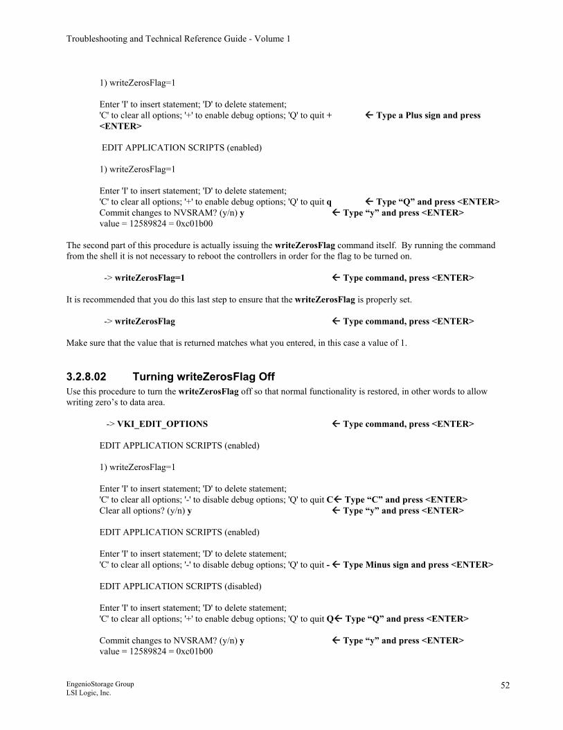
Troubleshooting and Technical Reference Guide - Volume 1
1) writeZerosFlag=1 Enter 'I' to insert statement; 'D' to delete statement; 'C' to clear all options; '+' to enable debug options; 'Q' to quit + Type a Plus sign and press <ENTER> EDIT APPLICATION SCRIPTS (enabled) 1) writeZerosFlag=1 Enter 'I' to insert statement; 'D' to delete statement; 'C' to clear all options; '+' to enable debug options; 'Q' to quit q Type “Q” and press <ENTER> Commit changes to NVSRAM? (y/n) y Type “y” and press <ENTER> value = 12589824 = 0xc01b00
The second part of this procedure is actually issuing the writeZerosFlag command itself. By running the command from the shell it is not necessary to reboot the controllers in order for the flag to be turned on.
-> writeZerosFlag=1 Type command, press <ENTER>
It is recommended that you do this last step to ensure that the writeZerosFlag is properly set.
-> writeZerosFlag Type command, press <ENTER>
Make sure that the value that is returned matches what you entered, in this case a value of 1.
3.2.8.02 Turning writeZerosFlag Off Use this procedure to turn the writeZerosFlag off so that normal functionality is restored, in other words to allow writing zero’s to data area.
-> VKI_EDIT_OPTIONS Type command, press <ENTER> EDIT APPLICATION SCRIPTS (enabled) 1) writeZerosFlag=1 Enter 'I' to insert statement; 'D' to delete statement; 'C' to clear all options; '-' to disable debug options; 'Q' to quit C Type “C” and press <ENTER> Clear all options? (y/n) y Type “y” and press <ENTER> EDIT APPLICATION SCRIPTS (enabled) Enter 'I' to insert statement; 'D' to delete statement; 'C' to clear all options; '-' to disable debug options; 'Q' to quit - Type Minus sign and press <ENTER> EDIT APPLICATION SCRIPTS (disabled) Enter 'I' to insert statement; 'D' to delete statement; 'C' to clear all options; '+' to enable debug options; 'Q' to quit Q Type “Q” and press <ENTER> Commit changes to NVSRAM? (y/n) y Type “y” and press <ENTER> value = 12589824 = 0xc01b00
EngenioStorage Group LSI Logic, Inc.
52
Troubleshooting and Technical Reference Guide - Volume 1
-> writeZerosFlag=0 Type command, press <ENTER> It is recommended that you do this last step to ensure that the writeZerosFlag is properly set.
-> writeZerosFlag Type command, press <ENTER>
Make sure that the value that is returned matches what you entered, in this case a value of 0.
3.2.9 Reviving a Dead Volume 1. Determine the order of failure of the drives. There are several different ways to determine the order of drive
failures. For best results use two of the three to confirm order.
• cfgPbDev • Check the state of the volume (vd_state) as seen by each failed drive. The drive that shows a
different state than the, i.e. volume optimal vs. volume degraded is the first failed drive. • If the drive's last view of the LUN was an optimal LUN, then it was the first to fail. The second
drive to fail would show a state and status of degraded. All subsequent failing drives will show a dead LUN state and status.
• cfgPh • Look for the drive update time stamp of each of the failed drives.
• Check the Major Event Log
• Remember that these drive locations are physical not logical. • *** Caution: if drive failures occur close together, then the MEL may not be reliable.
• Do Not use “oos” from cfgUnit • “oos” means Out Of Service • The “oos” order may not reflect the order that the drives failed.
2. Fail any hot spares that are not in use. This is to prevent unwanted reconstruction to the hot spares during repair.
3. Spin up all failed drives to check for fail order • isp cfgPrepareDrive,0x<phyDev Address>
o isp cfgPrepareDrive,0x4cdd468 ( the leading 0 in the address can be dropped ) 4. Revive all but the first failed drive(s).
• isp cfgSetDevOper,0xc0000i • c = channel i = ID
5. Reconstruct the first failed drive last. • isp cfgReplaceDrive,0xc0000i or • Remove the first failed drive, wait 60 seconds, then reinsert drive. This will power cycle the drive
plus perform the cfgPrepareDrive & cfgReplaceDrive commands automatically. 6. Revive the hot spares once reconstruction has begun.
3.2.10 Deleting a Host Port from the Shell Symptoms
Host port does not show up in available host ports list in SANtricity Cannot map a host port
Fix -> spmShow SPM controllerRef=070000000000000000000001 ssidMax=129 lunMax=10 SAP SAPORT_REF CONTROLLER_REF PORT SAPRTGRP_REF (0x3e3b5a8) SAP 800300010000 070000000000000000000002 0 000000000000 SAP 800300011000 070000000000000000000001 0 000000000000 HP HOSTPORT_REF TYPE NAME LABEL HOST_REF (0x3e35c44)
EngenioStorage Group LSI Logic, Inc.
53
Troubleshooting and Technical Reference Guide - Volume 1
HP 820300020000 2 0x20000001738119BA fcaw1-20 840300020000 HostControlled HP 820300020001 2 0x20000001730119BA fcaw0-20 840300020000 HostControlled HP 820300030006 2 0x200000017301199A hbaA_17 000000000000 HP 820300030007 2 0x20000001730119AE hba0-17 840300030005 HostControlled To delete the host port of label hbaA-17 run the command: -> deleteHostPort_MT 0x00030006 where 0x00030006 is the host hostport_ref value that you want to delete. The "0x00030006" above is the rightmost 8 digits of the hostportref value for the hostport to be deleted.
Note The controller has a mapping for this host port that does not show up in SANtricity.
3.2.11 Volume is not accessible from the host Facts
Array and volumes are all optimal. No pieces are out of service. State and status of LUN are optimal. vd_oos = -1 vd_oos2 = -1 vd_ooscnt = 0 All drives must be Optimal/Null
Symptoms Volume is not accessible from the host. vdShow lists volume as 'offline closed suspended'
Fix From the shell prompt, type the following command: -> cfgConfigVdisk X
Where X is the LUN number that will be changed back to 'online open optimal'.
3.2.12 Drive path redundancy lost Fact
It may be possible to recover the path by running a command to poll the chip for the path that is failed Notice that the path that is failed above is 1
Symptom You may see something like this output from fcDevs 4: Disk 00a00009 5,1 a7 Cur:0 Fail:1 Disk 00a0000a 5,2 a6 Cur:0 Fail:1 Disk 00a0000b 5,3 a5 Cur:0 Fail:1 Disk 00a0000c 5,4 a3 Cur:0 Fail:1 Disk 00a0000d 5,5 9f Cur:0 Alt:1
Fix -> fcChip=x where x = the chip relating to the path that is failed, i.e. 1 in the above example (Sets this as the active chip) -> fcSendPrim 5 5 is the option to poll the path
Note This may not always work, but is an easy solution to try first.
EngenioStorage Group LSI Logic, Inc.
54
Troubleshooting and Technical Reference Guide - Volume 1
3.2.13 How to retrieve the Major Event Log (MEL) from the shell To display a summary of all MEL event entries: -> showMajorEvents -1,-1,0 current 0x1621 critical 0x1611 max 0x2000 timeStamp 40e1e484 start 0x0 0x0 Event Seq Num id time dev lun . . . 2117 CCM_ERR_CLEARE 000003eb 0048210a 02/17/04 15:30:30 00000000 0 2114 ALT_CACHE_BATT 000003ec 00000000 02/17/04 15:30:30 00000000 0 2024 SCRUB_RESUME 000003ed 00000000 02/17/04 15:31:33 10000001 1 . . . 0000 Unknown Event 00000000 00000000 01/01/70 00:00:00 00000000 0
To display a specific event or group of events starting at a given point with more detail: -> showMajorEvents 1004,1,4 current 0x1621 critical 0x1611 max 0x2000 timeStamp 40e1e484 start 0x0 0x0 Event Seq Num id time dev lun org ctl evd len 00492114 ALT_CACHE_BATT_ 000003ec 00000000 02/17/04 15:30:30 00000000 0 00 1 00 0
In the above example, the commands first parameter is the event sequence number expressed in decimal format (not hex as in the example to display all events). The second parameter is how many events are to be listed, including the beginning event. The last parameter is setting the level of detail. Usually the number that should be used is four (4).
3.2.14 Adding drives that have a previous DacStor on them There are three different methods to allow adding drives that have a previous DacStor on them so that this information does not create a condition known as “dirty DacStor” from occurring. Method #1
-> isp cfgWipe1,0xc0000i ( this would be for a drive at c,i) -> isp rdacMgrAltCtlReset (this will do a quick reboot of the alternate controller) -> reboot (this will do a quick reboot of the controller currently logged into) Now look at the drive in cfgPhy c,i it should be: d_state=2 d_status=0 If the drive is to be moved from one storage array system to a different one, then the two reboots are not required as the drive will see the insertion into the foreign array the same as if the controllers had been rebooted.
Method #2 Disable Drive Migration by turning on bit 1 in Offset 35 of the Global NVSRAM region. This can be done using the Script Editor using the following script:
// Turn drive migration off by setting bit 1 offset 0x35 set controller[a] Globalnvsrambyte[0x35]=0x02,0x02; set controller[b] Globalnvsrambyte[0x35]=0x02,0x02; show controller[a] Globalnvsrambyte[0x35]; show controller[b] Globalnvsrambyte[0x35]; show "Drive migration is now disabled."; // Reboot controllers one at a time for NVSRAM changes to take effect show "Rebooting A controller.";
EngenioStorage Group LSI Logic, Inc.
55
Troubleshooting and Technical Reference Guide - Volume 1
reset controller[a]; show "A controller has rebooted."; show "Rebooting B controller."; reset controller[b]; show "B controller has rebooted.";
By disabling the drive migration feature, any drive that is inserted into a slot that the drive did not previously occupy will cause the array to write new DacStor to the drive. This would include not only foreign drives, but also drives from the same array that had been in a previously different slot so caution is advised. Method #3 Using the Global Hot Spare slot will also clear DacStor
3.2.15 Changing the modification priority Establish a shell connection to the controller that owns the lun/volume. At the prompt type: -> isp cfgSetReconParams,x,0xffff X=lun to be reconstructed ffff= 100% bfff=75% (This is the default value in the GUI) 7fff=50% 3fff=25% NOTE: While the value is set to ffff, any storage system access will be impacted. After the reconstruction/modification is complete, the default value will have to be reset using the same command with the default value of bfff or lower.
3.2.16 How to identify a drive from the shell *** Note: These commands use id,ch not ch,id as most commands are. To identify a drive use the following command: -> setDriveIdentify id,ch This will flash the fault light on the drive in question. To turn the light off. -> resetDriveIdentify id,ch
3.2.17 How to create and delete a Global Hot Spare from the shell Create Hot Spare -> isp cfgMarkDriveHotSpare,0xc0000i,0 Remove Hot Spare -> isp cfgRemoveHotSpare,0xc0000i,0
3.2.18 Monitoring and Stopping Media Scan from the shell Use the mon command to determine the progress of any media scans that are currently running. This command can only be stopped with a CTRL-C. The middle parameter represents the intervals in seconds between each reading taken.
-> mon 7,10,1 Monitoring Virtual Disk Background Operations at 10 second intervals 20:50:23 Scrub 0 96% | Scrub 1 5% | Scrub 2 96% | Scrub 3 17% block 2822283264 | block 210599936 | block 1885282304 | block 170801152
EngenioStorage Group LSI Logic, Inc.
56
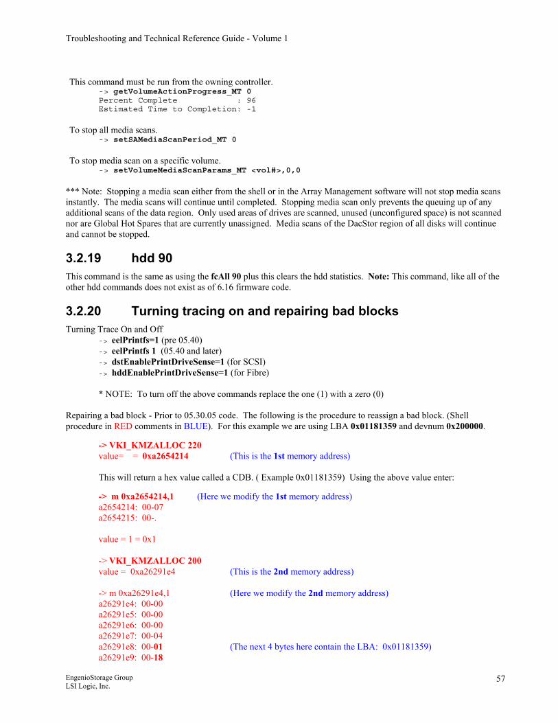
Troubleshooting and Technical Reference Guide - Volume 1
This command must be run from the owning controller.
-> getVolumeActionProgress_MT 0 Percent Complete : 96 Estimated Time to Completion: -1
To stop all media scans.
-> setSAMediaScanPeriod_MT 0
To stop media scan on a specific volume.
-> setVolumeMediaScanParams_MT <vol#>,0,0
*** Note: Stopping a media scan either from the shell or in the Array Management software will not stop media scans instantly. The media scans will continue until completed. Stopping media scan only prevents the queuing up of any additional scans of the data region. Only used areas of drives are scanned, unused (unconfigured space) is not scanned nor are Global Hot Spares that are currently unassigned. Media scans of the DacStor region of all disks will continue and cannot be stopped.
3.2.19 hdd 90 This command is the same as using the fcAll 90 plus this clears the hdd statistics. Note: This command, like all of the other hdd commands does not exist as of 6.16 firmware code.
3.2.20 Turning tracing on and repairing bad blocks Turning Trace On and Off
-> eelPrintfs=1 (pre 05.40) -> eelPrintfs 1 (05.40 and later) -> dstEnablePrintDriveSense=1 (for SCSI) -> hddEnablePrintDriveSense=1 (for Fibre) * NOTE: To turn off the above commands replace the one (1) with a zero (0)
Repairing a bad block - Prior to 05.30.05 code. The following is the procedure to reassign a bad block. (Shell procedure in RED comments in BLUE). For this example we are using LBA 0x01181359 and devnum 0x200000.
-> VKI_KMZALLOC 220 value= = 0xa2654214 (This is the 1st memory address) This will return a hex value called a CDB. ( Example 0x01181359) Using the above value enter:
-> m 0xa2654214,1 (Here we modify the 1st memory address) a2654214: 00-07 a2654215: 00-. value = 1 = 0x1 -> VKI_KMZALLOC 200 value = 0xa26291e4 (This is the 2nd memory address) -> m 0xa26291e4,1 (Here we modify the 2nd memory address) a26291e4: 00-00 a26291e5: 00-00 a26291e6: 00-00 a26291e7: 00-04 a26291e8: 00-01 (The next 4 bytes here contain the LBA: 0x01181359) a26291e9: 00-18
EngenioStorage Group LSI Logic, Inc.
57
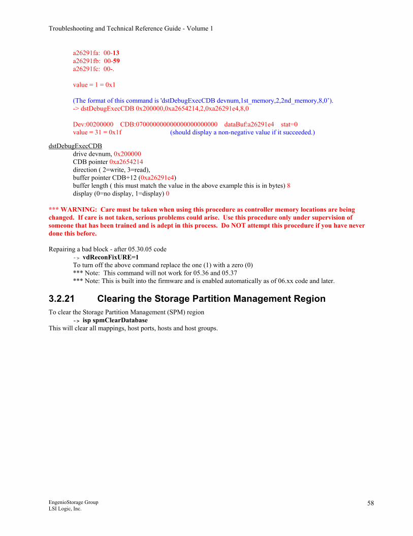
Troubleshooting and Technical Reference Guide - Volume 1
a26291fa: 00-13 a26291fb: 00-59 a26291fc: 00-. value = 1 = 0x1 (The format of this command is 'dstDebugExecCDB devnum,1st_memory,2,2nd_memory,8,0’). -> dstDebugExecCDB 0x200000,0xa2654214,2,0xa26291e4,8,0 Dev:00200000 CDB:070000000000000000000000 dataBuf:a26291e4 stat=0 value = 31 = 0x1f (should display a non-negative value if it succeeded.)
dstDebugExecCDB drive devnum, 0x200000 CDB pointer 0xa2654214 direction ( 2=write, 3=read), buffer pointer CDB+12 (0xa26291e4) buffer length ( this must match the value in the above example this is in bytes) 8 display (0=no display, 1=display) 0
*** WARNING: Care must be taken when using this procedure as controller memory locations are being changed. If care is not taken, serious problems could arise. Use this procedure only under supervision of someone that has been trained and is adept in this process. Do NOT attempt this procedure if you have never done this before.
Repairing a bad block - after 05.30.05 code -> vdReconFixURE=1 To turn off the above command replace the one (1) with a zero (0) *** Note: This command will not work for 05.36 and 05.37 *** Note: This is built into the firmware and is enabled automatically as of 06.xx code and later.
3.2.21 Clearing the Storage Partition Management Region To clear the Storage Partition Management (SPM) region
-> isp spmClearDatabase This will clear all mappings, host ports, hosts and host groups.
EngenioStorage Group LSI Logic, Inc.
58
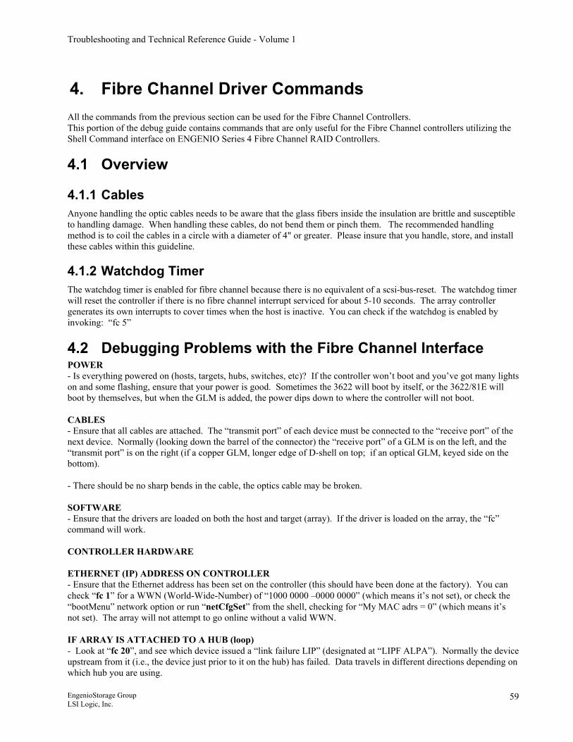
Troubleshooting and Technical Reference Guide - Volume 1
4. Fibre Channel Driver Commands All the commands from the previous section can be used for the Fibre Channel Controllers. This portion of the debug guide contains commands that are only useful for the Fibre Channel controllers utilizing the Shell Command interface on ENGENIO Series 4 Fibre Channel RAID Controllers.
4.1 Overview
4.1.1 Cables Anyone handling the optic cables needs to be aware that the glass fibers inside the insulation are brittle and susceptible to handling damage. When handling these cables, do not bend them or pinch them. The recommended handling method is to coil the cables in a circle with a diameter of 4" or greater. Please insure that you handle, store, and install these cables within this guideline.
4.1.2 Watchdog Timer The watchdog timer is enabled for fibre channel because there is no equivalent of a scsi-bus-reset. The watchdog timer will reset the controller if there is no fibre channel interrupt serviced for about 5-10 seconds. The array controller generates its own interrupts to cover times when the host is inactive. You can check if the watchdog is enabled by invoking: “fc 5”
4.2 Debugging Problems with the Fibre Channel Interface POWER - Is everything powered on (hosts, targets, hubs, switches, etc)? If the controller won’t boot and you’ve got many lights on and some flashing, ensure that your power is good. Sometimes the 3622 will boot by itself, or the 3622/81E will boot by themselves, but when the GLM is added, the power dips down to where the controller will not boot. CABLES - Ensure that all cables are attached. The “transmit port” of each device must be connected to the “receive port” of the next device. Normally (looking down the barrel of the connector) the “receive port” of a GLM is on the left, and the “transmit port” is on the right (if a copper GLM, longer edge of D-shell on top; if an optical GLM, keyed side on the bottom). - There should be no sharp bends in the cable, the optics cable may be broken. SOFTWARE - Ensure that the drivers are loaded on both the host and target (array). If the driver is loaded on the array, the “fc” command will work. CONTROLLER HARDWARE ETHERNET (IP) ADDRESS ON CONTROLLER - Ensure that the Ethernet address has been set on the controller (this should have been done at the factory). You can check “fc 1” for a WWN (World-Wide-Number) of “1000 0000 –0000 0000” (which means it’s not set), or check the “bootMenu” network option or run “netCfgSet” from the shell, checking for “My MAC adrs = 0” (which means it’s not set). The array will not attempt to go online without a valid WWN. IF ARRAY IS ATTACHED TO A HUB (loop) - Look at “fc 20”, and see which device issued a “link failure LIP” (designated at “LIPF ALPA”). Normally the device upstream from it (i.e., the device just prior to it on the hub) has failed. Data travels in different directions depending on which hub you are using.
EngenioStorage Group LSI Logic, Inc.
59
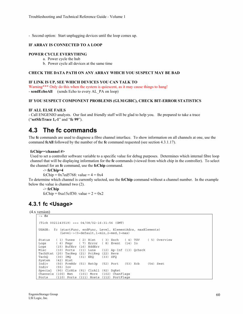
Troubleshooting and Technical Reference Guide - Volume 1
- Second option: Start unplugging devices until the loop comes up. IF ARRAY IS CONNECTED TO A LOOP POWER CYCLE EVERYTHING a. Power cycle the hub b. Power cycle all devices at the same time CHECK THE DATA PATH ON ANY ARRAY WHICH YOU SUSPECT MAY BE BAD IF LINK IS UP, SEE WHICH DEVICES YOU CAN TALK TO Warning*** Only do this when the system is quiescent, as it may cause things to hang! - sendEchoAll (sends Echo to every AL_PA on loop) IF YOU SUSPECT COMPONENT PROBLEMS (GLM/GBIC), CHECK BIT-ERROR STATISTICS IF ALL ELSE FAILS - Call ENGENIO analysts. Our fast and friendly staff will be glad to help you. Be prepared to take a trace (“setSfcTrace 1,-1” and “fc 99”).
4.3 The fc commands The fc commands are used to diagnose a fibre channel interface. To show information on all channels at one, use the command fcAll followed by the number of the fc command requested (see section 4.3.1.17). fcChip=<channel #> Used to set a controller software variable to a specific value for debug purposes. Determines which internal fibre loop channel that will be displaying information for the fc commands (viewed from which chip in the controller). To select the channel for an fc command, use the fcChip command.
-> fcChip=4 fcChip = 0x7ed5768: value = 4 = 0x4
To determine which channel is currently selected, use the fcChip command without a channel number. In the example below the value is channel two (2).
-> fcChip fcChip = 0xa15cff30: value = 2 = 0x2
4.3.1 fc <Usage> (4.x version)
-> fc (Tick 0021143519) ==> 04/08/02-16:31:56 (GMT) USAGE: fc (startFunc, endFunc, Level, ElementAdrs, maxElements) (Level->(0=default,1=min,2=med,3=max) Status ( 1) Tunes ( 2) Hist ( 3) Exch ( 4) TGV ( 5) Overview Logs ( 6) Fmgr ( 7) Error ( 8) Event (14) Io Logs (15) BufErr (16) HddErr Misc (10) Ports (11) Luns (12) Ap-Inf (13) Qcheck TachStat (20) TacReg (21) PciReg (22) Revs TachQ (30) IMQ (31) ERQ (33) SFQ System (42) Hist Indiv (50) FrmHdr (51) HstOp (52) Port (53) Xcb (54) Sest Indiv (55) Iov Special (90) ClrHis (91) ClrAll (92) DqRst Channels (100) Wwn (101) More (102) ChanFlags Ports (110) Ports (111) Hosts (112) PortFlags
EngenioStorage Group LSI Logic, Inc.
60
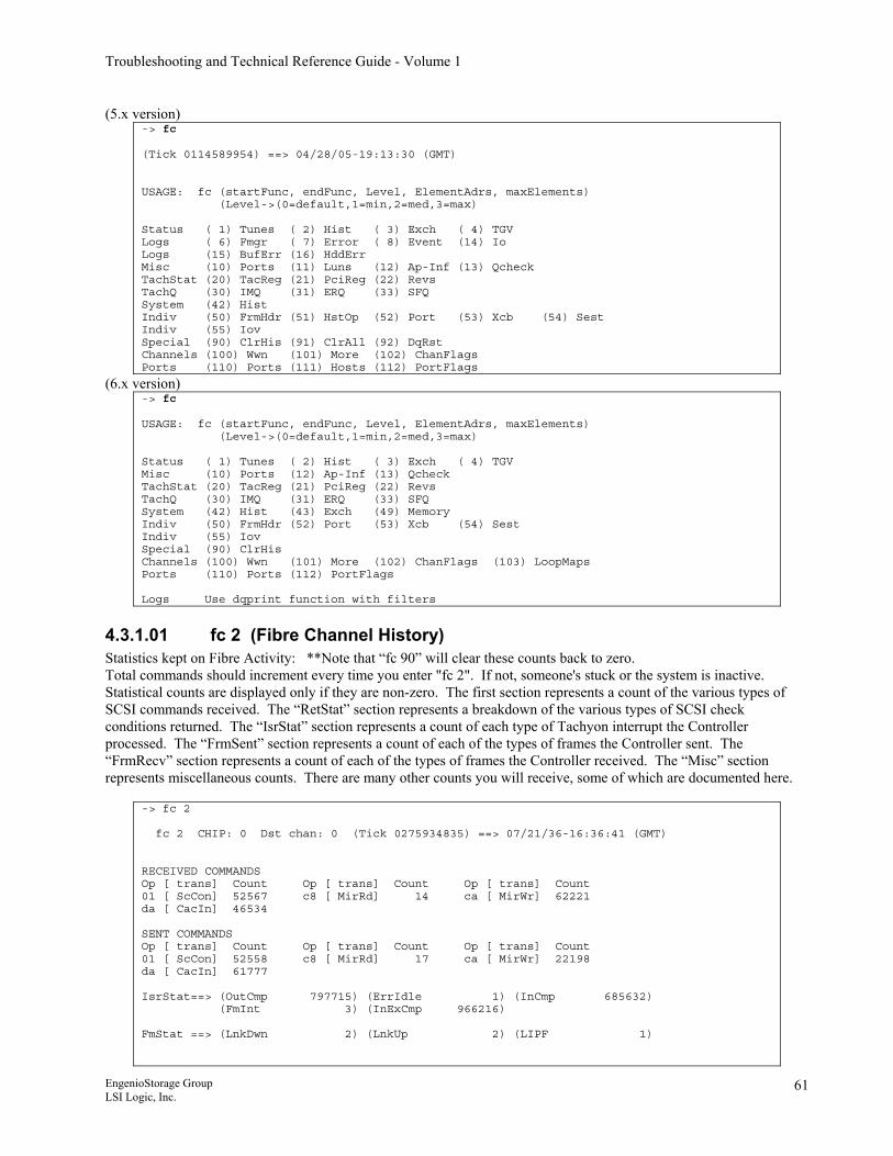
Troubleshooting and Technical Reference Guide - Volume 1
(5.x version) -> fc (Tick 0114589954) ==> 04/28/05-19:13:30 (GMT) USAGE: fc (startFunc, endFunc, Level, ElementAdrs, maxElements) (Level->(0=default,1=min,2=med,3=max) Status ( 1) Tunes ( 2) Hist ( 3) Exch ( 4) TGV Logs ( 6) Fmgr ( 7) Error ( 8) Event (14) Io Logs (15) BufErr (16) HddErr Misc (10) Ports (11) Luns (12) Ap-Inf (13) Qcheck TachStat (20) TacReg (21) PciReg (22) Revs TachQ (30) IMQ (31) ERQ (33) SFQ System (42) Hist Indiv (50) FrmHdr (51) HstOp (52) Port (53) Xcb (54) Sest Indiv (55) Iov Special (90) ClrHis (91) ClrAll (92) DqRst Channels (100) Wwn (101) More (102) ChanFlags Ports (110) Ports (111) Hosts (112) PortFlags
(6.x version) -> fc USAGE: fc (startFunc, endFunc, Level, ElementAdrs, maxElements) (Level->(0=default,1=min,2=med,3=max) Status ( 1) Tunes ( 2) Hist ( 3) Exch ( 4) TGV Misc (10) Ports (12) Ap-Inf (13) Qcheck TachStat (20) TacReg (21) PciReg (22) Revs TachQ (30) IMQ (31) ERQ (33) SFQ System (42) Hist (43) Exch (49) Memory Indiv (50) FrmHdr (52) Port (53) Xcb (54) Sest Indiv (55) Iov Special (90) ClrHis Channels (100) Wwn (101) More (102) ChanFlags (103) LoopMaps Ports (110) Ports (112) PortFlags Logs Use dqprint function with filters
4.3.1.01 fc 2 (Fibre Channel History) Statistics kept on Fibre Activity: **Note that “fc 90” will clear these counts back to zero. Total commands should increment every time you enter "fc 2". If not, someone's stuck or the system is inactive. Statistical counts are displayed only if they are non-zero. The first section represents a count of the various types of SCSI commands received. The “RetStat” section represents a breakdown of the various types of SCSI check conditions returned. The “IsrStat” section represents a count of each type of Tachyon interrupt the Controller processed. The “FrmSent” section represents a count of each of the types of frames the Controller sent. The “FrmRecv” section represents a count of each of the types of frames the Controller received. The “Misc” section represents miscellaneous counts. There are many other counts you will receive, some of which are documented here.
-> fc 2 fc 2 CHIP: 0 Dst chan: 0 (Tick 0275934835) ==> 07/21/36-16:36:41 (GMT) RECEIVED COMMANDS Op [ trans] Count Op [ trans] Count Op [ trans] Count 01 [ ScCon] 52567 c8 [ MirRd] 14 ca [ MirWr] 62221 da [ CacIn] 46534 SENT COMMANDS Op [ trans] Count Op [ trans] Count Op [ trans] Count 01 [ ScCon] 52558 c8 [ MirRd] 17 ca [ MirWr] 22198 da [ CacIn] 61777 IsrStat==> (OutCmp 797715) (ErrIdle 1) (InCmp 685632) (FmInt 3) (InExCmp 966216) FmStat ==> (LnkDwn 2) (LnkUp 2) (LIPF 1)
EngenioStorage Group LSI Logic, Inc.
61
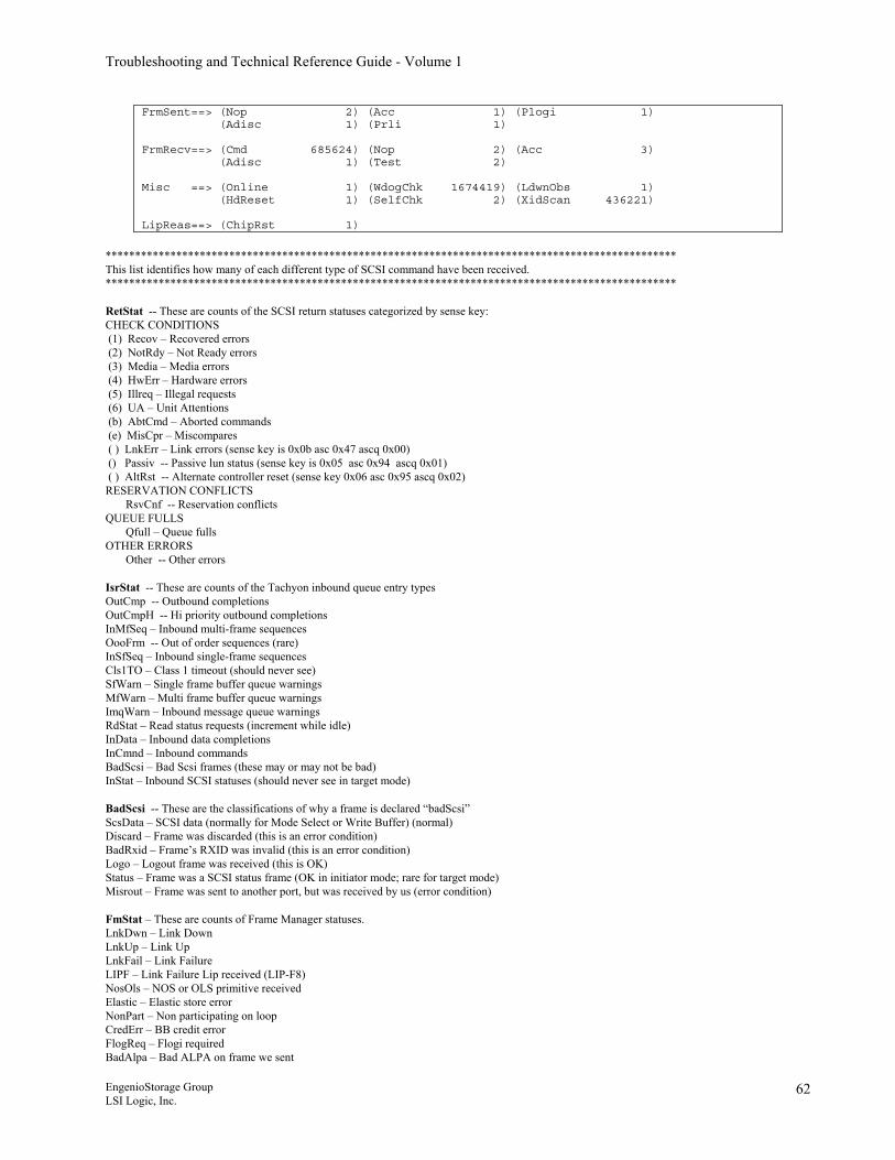
Troubleshooting and Technical Reference Guide - Volume 1
FrmSent==> (Nop 2) (Acc 1) (Plogi 1) (Adisc 1) (Prli 1) FrmRecv==> (Cmd 685624) (Nop 2) (Acc 3) (Adisc 1) (Test 2) Misc ==> (Online 1) (WdogChk 1674419) (LdwnObs 1) (HdReset 1) (SelfChk 2) (XidScan 436221) LipReas==> (ChipRst 1)
************************************************************************************************* This list identifies how many of each different type of SCSI command have been received. ************************************************************************************************* RetStat -- These are counts of the SCSI return statuses categorized by sense key: CHECK CONDITIONS (1) Recov – Recovered errors (2) NotRdy – Not Ready errors (3) Media – Media errors (4) HwErr – Hardware errors (5) Illreq – Illegal requests (6) UA – Unit Attentions (b) AbtCmd – Aborted commands (e) MisCpr – Miscompares ( ) LnkErr – Link errors (sense key is 0x0b asc 0x47 ascq 0x00) () Passiv -- Passive lun status (sense key is 0x05 asc 0x94 ascq 0x01) ( ) AltRst -- Alternate controller reset (sense key 0x06 asc 0x95 ascq 0x02) RESERVATION CONFLICTS RsvCnf -- Reservation conflicts QUEUE FULLS Qfull – Queue fulls OTHER ERRORS Other -- Other errors IsrStat -- These are counts of the Tachyon inbound queue entry types OutCmp -- Outbound completions OutCmpH -- Hi priority outbound completions InMfSeq – Inbound multi-frame sequences OooFrm -- Out of order sequences (rare) InSfSeq – Inbound single-frame sequences Cls1TO – Class 1 timeout (should never see) SfWarn – Single frame buffer queue warnings MfWarn – Multi frame buffer queue warnings ImqWarn – Inbound message queue warnings RdStat – Read status requests (increment while idle) InData – Inbound data completions InCmnd – Inbound commands BadScsi – Bad Scsi frames (these may or may not be bad) InStat – Inbound SCSI statuses (should never see in target mode) BadScsi -- These are the classifications of why a frame is declared “badScsi” ScsData – SCSI data (normally for Mode Select or Write Buffer) (normal) Discard – Frame was discarded (this is an error condition) BadRxid – Frame’s RXID was invalid (this is an error condition) Logo – Logout frame was received (this is OK) Status – Frame was a SCSI status frame (OK in initiator mode; rare for target mode) Misrout – Frame was sent to another port, but was received by us (error condition) FmStat – These are counts of Frame Manager statuses. LnkDwn – Link Down LnkUp – Link Up LnkFail – Link Failure LIPF – Link Failure Lip received (LIP-F8) NosOls – NOS or OLS primitive received Elastic – Elastic store error NonPart – Non participating on loop CredErr – BB credit error FlogReq – Flogi required BadAlpa – Bad ALPA on frame we sent
EngenioStorage Group LSI Logic, Inc.
62
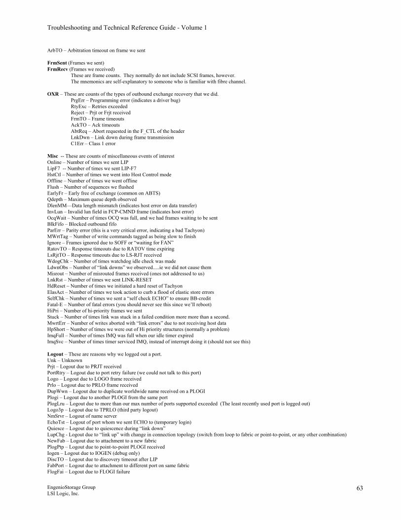
Troubleshooting and Technical Reference Guide - Volume 1
ArbTO – Arbitration timeout on frame we sent FrmSent (Frames we sent) FrmRecv (Frames we received) These are frame counts. They normally do not include SCSI frames, however. The mnemonics are self-explanatory to someone who is familiar with fibre channel. OXR – These are counts of the types of outbound exchange recovery that we did. PrgErr – Programming error (indicates a driver bug) RtyExc – Retries exceeded Reject – Prjt or Frjt received FrmTO – Frame timeouts AckTO – Ack timeouts AbtReq – Abort requested in the F_CTL of the header LnkDwn – Link down during frame transmission C1Err – Class 1 error Misc -- These are counts of miscellaneous events of interest Online – Number of times we sent LIP LipF7 -- Number of times we sent LIP-F7 HstCtl – Number of times we went into Host Control mode Offline – Number of times we went offline Flush – Number of sequences we flushed EarlyFr – Early free of exchange (common on ABTS) Qdepth – Maximum queue depth observed DlenMM—Data length mismatch (indicates host error on data transfer) InvLun – Invalid lun field in FCP-CMND frame (indicates host error) OcqWait – Number of times OCQ was full, and we had frames waiting to be sent BlkFifo – Blocked outbound fifo ParErr – Parity error (this is a very critical error, indicating a bad Tachyon) MWrtTag – Number of write commands tagged as being slow to finish Ignore – Frames ignored due to SOFF or “waiting for FAN” RatovTO – Response timeouts due to RATOV time expiring LsRjtTO – Response timeouts due to LS-RJT received WdogChk – Number of times watchdog idle check was made LdwnObs – Number of “link downs” we observed.....ie we did not cause them Misrout – Number of misrouted frames received (ones not addressed to us) LnkRst – Number of times we sent LINK-RESET HdReset – Number of times we initiated a hard reset of Tachyon ElasAct – Number of times we took action to curb a flood of elastic store errors SelfChk – Number of times we sent a “self check ECHO” to ensure BB-credit Fatal-E – Number of fatal errors (you should never see this since we’ll reboot) HiPri – Number of hi-priority frames we sent Stuck – Number of times link was stuck in a failed condition more more than a second. MwrtErr – Number of writes aborted with “link errors” due to not receiving host data HpShort – Number of times we were out of Hi priority structures (normally a problem) ImqFull – Number of times IMQ was full when our idle timer expired ImqSvc – Number of times timer serviced IMQ, instead of interrupt doing it (should not see this) Logout – These are reasons why we logged out a port. Unk – Unknown Prjt – Logout due to PRJT received PortRtry – Logout due to port retry failure (we could not talk to this port) Logo – Logout due to LOGO frame received Prlo – Logout due to PRLO frame received DupWwn – Logout due to duplicate worldwide name received on a PLOGI Plogi – Logout due to another PLOGI from the same port PlogLru – Logout due to more than our max number of ports supported exceeded (The least recently used port is logged out) Logo3p – Logout due to TPRLO (third party logout) NmSrvr – Logout of name server EchoTst – Logout of port whom we sent ECHO to (temporary login) Quiesce – Logout due to quiescence during “link down” LupChg - Logout due to “link up” with change in connection topology (switch from loop to fabric or point-to-point, or any other combination) NewFab – Logout due to attachment to a new fabric PlogPtp – Logout due to point-to-point PLOGI received Iogen – Logout due to IOGEN (debug only) DiscTO – Logout due to discovery timeout after LIP FabPort – Logout due to attachment to different port on same fabric FlogFai – Logout due to FLOGI failure
EngenioStorage Group LSI Logic, Inc.
63
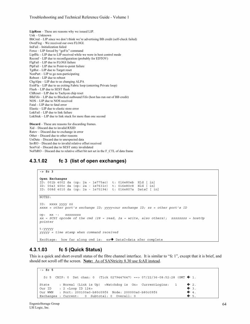
Troubleshooting and Technical Reference Guide - Volume 1
LipReas – These are reasons why we issued LIP. Unk – Unknown BbCred – LIP since we don’t think we’re advertising BB credit (self-check failed) OwnFlog – We received our own FLOGI. IniFail – Initialization failed Force – LIP forced by “goFix” command LipfHc – LIP due to LIP received while we were in host control mode Reconf – LIP due to reconfiguration (probably for EDTOV) FlgFail – LIP due to FLOGI failure PtpFail – LIP due to Point-to-point failure TgtRst – LIP due to Target reset NonPart – LIP to go non-participating Reboot – LIP due to reboot ChgAlpa – LIP due to us changing ALPA ExitFla – LIP due to us exiting Fabric loop (enterring Private loop) Flush – LIP due to SEST flush ChReset – LIP due to Tachyon chip reset BlkFifo – LIP due to Blocked outbound Fifo (host has run out of BB credit) NOS – LIP due to NOS received Fatal – LIP due to fatal error Elastic – LIP due to elastic store error LnkFail – LIP due to link failure LnkStuk – LIP due to link stuck for more than one second Discard – These are reasons for discarding frames. Xid – Discard due to invalid RXID Ratov – Discard due to exchange in error Other – Discard due to other reasons UnData – Discard due to unexpected data InvRO – Discard due to invalid relative offset received SestVal – Discard due to SEST entry invalidated NoFhRO – Discard due to relative offset bit not set in the F_CTL of data frame
4.3.1.02 fc 3 (list of open exchanges)
-> fc 3 Open Exchanges ID: 001b 4002 da (op: 2a - 1e775ac) t: 016e80eb Hld [ in] ID: 00a3 400c da (op: 2a - 1e7631c) t: 016e80c8 Hld [ in] ID: 008d 4010 da (op: 2a - 1e75194) t: 016e807a DataC [ in] NOTES: ID: xxxx yyyy zz xxxx = other port’s exchange ID; yyyy=our exchange ID; zz = other port’s ID op: xx -: zzzzzzzz xx = SCSI opcode of the cmd (28 = read, 2a = write, also others); zzzzzzzz = hostOp pointer t:yyyyy yyyyy = time stamp when command received ExcStage: how far along cmd is: ex DataC=data xfer complete
4.3.1.03 fc 5 (Quick Status) This is a quick and short overall status of the fibre channel interface. It is similar to “fc 1”, except that it is brief, and should not scroll off the screen. Note: As of SANtricity 8.30 use fcAll instead.
-> fc 5 fc 5 CHIP: 0 Dst chan: 0 (Tick 0279447647) ==> 07/22/36-08:52:28 (GMT 1. State : Normal (Link is Up) <Watchdog is On> CurrentLogins: 1 2. Our ID : 2 <Loop ID 124> 3. Our WWN : Port: 200100a0-b80c09f6 Node: 200000a0-b80c09f6 4. Exchanges : Current: 0 Subtotal: 0 Overall: 0 5.
EngenioStorage Group LSI Logic, Inc.
64
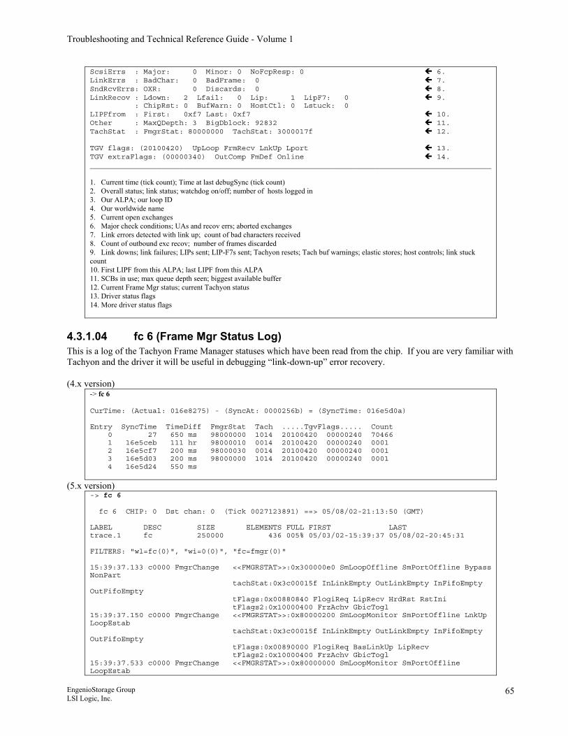
Troubleshooting and Technical Reference Guide - Volume 1
ScsiErrs : Major: 0 Minor: 0 NoFcpResp: 0 6. LinkErrs : BadChar: 0 BadFrame: 0 7. SndRcvErrs: OXR: 0 Discards: 0 8. LinkRecov : Ldown: 2 Lfail: 0 Lip: 1 LipF7: 0 9. : ChipRst: 0 BufWarn: 0 HostCtl: 0 Lstuck: 0 LIPFfrom : First: 0xf7 Last: 0xf7 10. Other : MaxQDepth: 3 BigDblock: 92832 11. TachStat : FmgrStat: 80000000 TachStat: 3000017f 12. TGV flags: (20100420) UpLoop FrmRecv LnkUp Lport 13. TGV extraFlags: (00000340) OutComp FmDef Online 14. __________________________________________________________________________________________ 1. Current time (tick count); Time at last debugSync (tick count) 2. Overall status; link status; watchdog on/off; number of hosts logged in 3. Our ALPA; our loop ID 4. Our worldwide name 5. Current open exchanges 6. Major check conditions; UAs and recov errs; aborted exchanges 7. Link errors detected with link up; count of bad characters received 8. Count of outbound exc recov; number of frames discarded 9. Link downs; link failures; LIPs sent; LIP-F7s sent; Tachyon resets; Tach buf warnings; elastic stores; host controls; link stuck count 10. First LIPF from this ALPA; last LIPF from this ALPA 11. SCBs in use; max queue depth seen; biggest available buffer 12. Current Frame Mgr status; current Tachyon status 13. Driver status flags 14. More driver status flags
4.3.1.04 fc 6 (Frame Mgr Status Log) This is a log of the Tachyon Frame Manager statuses which have been read from the chip. If you are very familiar with Tachyon and the driver it will be useful in debugging “link-down-up” error recovery. (4.x version)
-> fc 6 CurTime: (Actual: 016e8275) - (SyncAt: 0000256b) = (SyncTime: 016e5d0a) Entry SyncTime TimeDiff FmgrStat Tach .....TgvFlags..... Count 0 27 650 ms 98000000 1014 20100420 00000240 70466 1 16e5ceb 111 hr 98000010 0014 20100420 00000240 0001 2 16e5cf7 200 ms 98000030 0014 20100420 00000240 0001 3 16e5d03 200 ms 98000000 1014 20100420 00000240 0001 4 16e5d24 550 ms
(5.x version) -> fc 6 fc 6 CHIP: 0 Dst chan: 0 (Tick 0027123891) ==> 05/08/02-21:13:50 (GMT) LABEL DESC SIZE ELEMENTS FULL FIRST LAST trace.1 fc 250000 436 005% 05/03/02-15:39:37 05/08/02-20:45:31 FILTERS: "wl=fc(0)", "wi=0(0)", "fc=fmgr(0)" 15:39:37.133 c0000 FmgrChange <<FMGRSTAT>>:0x300000e0 SmLoopOffline SmPortOffline Bypass NonPart tachStat:0x3c00015f InLinkEmpty OutLinkEmpty InFifoEmpty OutFifoEmpty tFlags:0x00880840 FlogiReq LipRecv HrdRst RstIni tFlags2:0x10000400 FrzAchv GbicTogl 15:39:37.150 c0000 FmgrChange <<FMGRSTAT>>:0x80000200 SmLoopMonitor SmPortOffline LnkUp LoopEstab tachStat:0x3c00015f InLinkEmpty OutLinkEmpty InFifoEmpty OutFifoEmpty tFlags:0x00890000 FlogiReq BasLinkUp LipRecv tFlags2:0x10000400 FrzAchv GbicTogl 15:39:37.533 c0000 FmgrChange <<FMGRSTAT>>:0x80000000 SmLoopMonitor SmPortOffline LoopEstab
EngenioStorage Group LSI Logic, Inc.
65
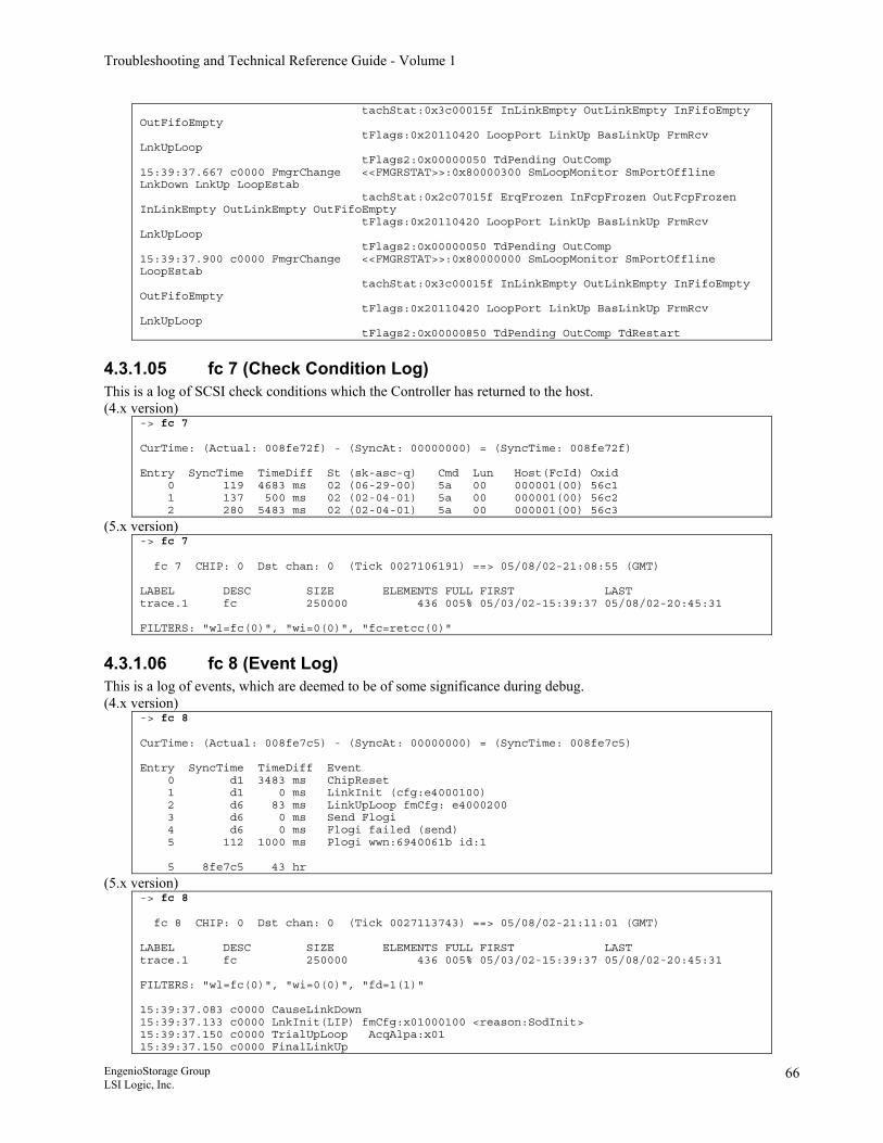
Troubleshooting and Technical Reference Guide - Volume 1
tachStat:0x3c00015f InLinkEmpty OutLinkEmpty InFifoEmpty OutFifoEmpty tFlags:0x20110420 LoopPort LinkUp BasLinkUp FrmRcv LnkUpLoop tFlags2:0x00000050 TdPending OutComp 15:39:37.667 c0000 FmgrChange <<FMGRSTAT>>:0x80000300 SmLoopMonitor SmPortOffline LnkDown LnkUp LoopEstab tachStat:0x2c07015f ErqFrozen InFcpFrozen OutFcpFrozen InLinkEmpty OutLinkEmpty OutFifoEmpty tFlags:0x20110420 LoopPort LinkUp BasLinkUp FrmRcv LnkUpLoop tFlags2:0x00000050 TdPending OutComp 15:39:37.900 c0000 FmgrChange <<FMGRSTAT>>:0x80000000 SmLoopMonitor SmPortOffline LoopEstab tachStat:0x3c00015f InLinkEmpty OutLinkEmpty InFifoEmpty OutFifoEmpty tFlags:0x20110420 LoopPort LinkUp BasLinkUp FrmRcv LnkUpLoop tFlags2:0x00000850 TdPending OutComp TdRestart
4.3.1.05 fc 7 (Check Condition Log) This is a log of SCSI check conditions which the Controller has returned to the host. (4.x version)
-> fc 7 CurTime: (Actual: 008fe72f) - (SyncAt: 00000000) = (SyncTime: 008fe72f) Entry SyncTime TimeDiff St (sk-asc-q) Cmd Lun Host(FcId) Oxid 0 119 4683 ms 02 (06-29-00) 5a 00 000001(00) 56c1 1 137 500 ms 02 (02-04-01) 5a 00 000001(00) 56c2 2 280 5483 ms 02 (02-04-01) 5a 00 000001(00) 56c3
(5.x version) -> fc 7 fc 7 CHIP: 0 Dst chan: 0 (Tick 0027106191) ==> 05/08/02-21:08:55 (GMT) LABEL DESC SIZE ELEMENTS FULL FIRST LAST trace.1 fc 250000 436 005% 05/03/02-15:39:37 05/08/02-20:45:31 FILTERS: "wl=fc(0)", "wi=0(0)", "fc=retcc(0)"
4.3.1.06 fc 8 (Event Log) This is a log of events, which are deemed to be of some significance during debug. (4.x version)
-> fc 8 CurTime: (Actual: 008fe7c5) - (SyncAt: 00000000) = (SyncTime: 008fe7c5) Entry SyncTime TimeDiff Event 0 d1 3483 ms ChipReset 1 d1 0 ms LinkInit (cfg:e4000100) 2 d6 83 ms LinkUpLoop fmCfg: e4000200 3 d6 0 ms Send Flogi 4 d6 0 ms Flogi failed (send) 5 112 1000 ms Plogi wwn:6940061b id:1 5 8fe7c5 43 hr
(5.x version) -> fc 8 fc 8 CHIP: 0 Dst chan: 0 (Tick 0027113743) ==> 05/08/02-21:11:01 (GMT) LABEL DESC SIZE ELEMENTS FULL FIRST LAST trace.1 fc 250000 436 005% 05/03/02-15:39:37 05/08/02-20:45:31 FILTERS: "wl=fc(0)", "wi=0(0)", "fd=1(1)" 15:39:37.083 c0000 CauseLinkDown 15:39:37.133 c0000 LnkInit(LIP) fmCfg:x01000100 <reason:SodInit> 15:39:37.150 c0000 TrialUpLoop AcqAlpa:x01 15:39:37.150 c0000 FinalLinkUp
EngenioStorage Group LSI Logic, Inc.
66
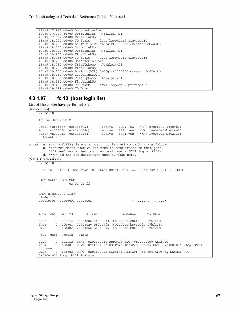
Troubleshooting and Technical Reference Guide - Volume 1
15:39:37.667 c0000 ObserveLinkDown 15:39:37.667 c0000 TrialUpLoop AcqAlpa:x01 15:39:37.667 c0000 FinalLinkUp 15:39:38.200 c0000 TD Start devs(loopMap:2 previous:0) 15:39:38.200 c0000 LnkInit(LIP) fmCfg:x01000200 <reason:TdCount> 15:39:38.200 c0000 CauseLinkDown 15:39:38.200 c0000 TrialUpLoop AcqAlpa:x01 15:39:38.200 c0000 FinalLinkUp 15:39:38.733 c0000 TD Start devs(loopMap:2 previous:2) 15:39:38.750 c0000 ObserveLinkDown 15:39:38.750 c0000 TrialUpLoop AcqAlpa:x01 15:39:38.750 c0000 FinalLinkUp 15:39:38.950 c0000 LnkInit(LIP) fmCfg:x01000200 <reason:SodInit> 15:39:38.950 c0000 CauseLinkDown 15:39:38.950 c0000 TrialUpLoop AcqAlpa:x01 15:39:38.950 c0000 FinalLinkUp 15:39:39.483 c0000 TD Start devs(loopMap:2 previous:2) 15:39:39.483 c0000 TD Done
4.3.1.07 fc 10 (host login list) List of Hosts who have performed login. (4.x version)
-> fc 10 Active dstNPort Q Port: 0xfffffe (0x01e6d7a4): active | FCP: no | WWN: 00000000-00000000 Port: 0x0000dc (0x01e6d86c): active | FCP: yes | WWN: 100000a0-b8028003 Port: 0x0000da (0x01e6d934): active | FCP: yes | WWN: 100000a0-b802116b (Count = 3)
NOTES: a. Port 0xfffffe is not a host. It is used to talk to the fabric. b. “active” means that we are free to send frames to that port. c. “FCP yes” means that port has performed a SCSI login (PRLI) d, “WWN” is the worldwide name used by that port.
(5.x & 6.x versions) -> fc 10 fc 10 CHIP: 0 Dst chan: 0 (Tick 0027150337) ==> 05/08/02-21:21:11 (GMT) LAST VALID LOOP MAP: 02 02 01 ff LAST DISCOVERY LIST: <Index: 0> 07c3f930: 00000001 00000002 *................* Role Chip PortId PortWwn NodeWwn DstNPort Dflt 0 fffffe 00000000-00000000 00000000-00000000 07bf21d8 This 0 000001 000000a0-b80cc7fa 000000a0-b80cc7fa 07bf2254 Lmir 0 000002 200100a0-b80c80a5 200000a0-b80c80a5 07bf22d0 Role Chip PortId Flags Dflt 0 fffffe PRMT: 0x00000010 AbDsReq FLG: 0x00001000 Analyze This 0 000001 PRMT: 0x1fd5e832 HddPort AbDsReq ShtSns FLG: 0x00001006 Plogi Prli Analyze Lmir 0 000002 PRMT: 0x0000003b LogiIni HddPort HsdPort AbDsReq ShtSns FLG: 0x00001006 Plogi Prli Analyze
EngenioStorage Group LSI Logic, Inc.
67
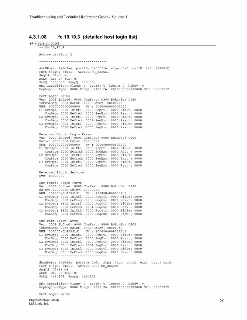
Troubleshooting and Technical Reference Guide - Volume 1
4.3.1.08 fc 10,10,3 (detailed host login list) (4.x version only)
-> fc 10,10,3 Active dstNPort Q ----------------------------------- dstNPort: 1e6d7a4 portID: 0xfffffe alpa: 0x0 ourID: 0x0 (FABRIC) Port flags: (4001) ACTIVE NO_EXLOGI SeqId (C2/3: a) ACK0 (C1: 0) (C2: 0) ScbQ: 1e6d830 SuspQ: 1e6d83c RNC Capability: Flags: 0 docId: 0 loRev: 0 hiRev: 0 FcpLogin--Type: 0800 Flags: 2100 PA: 0000000000000000 Svc: 00000012 Port Login Parms Ver: 2009 BbCred: 0000 ComFeat: 0800 BbRcvSz: 0080 TotConSeq: 0000 RoCat: 0000 EdTov: 00000000 WWN: 0000000000000000 NN : 0000000000000000 C1 SvcOpt: 0000 IniCtl: 0000 RcpCtl: 0000 FldSz: 0000 ConSeq: 0000 EeCred: 0000 SeqExc: 0000 Resv : 0000 C2 SvcOpt: 8000 IniCtl: 0000 RcpCtl: 0000 FldSz: 0080 ConSeq: 0000 EeCred: 0001 SeqExc: 0000 Resv : 0000 C3 SvcOpt: 8000 IniCtl: 0000 RcpCtl: 0000 FldSz: 0080 ConSeq: 0000 EeCred: 0000 SeqExc: 0000 Resv : 0000 Received Fabric Login Parms Ver: 0000 BbCred: 0000 ComFeat: 0000 BbRcvSz: 0000 RaTov: 00000000 EdTov: 00000000 WWN: 0000000000000000 NN : 0000000000000000 C1 SvcOpt: 0000 IniCtl: 0000 RcpCtl: 0000 FldSz: 0000 ConSeq: 0000 EeCred: 0000 SeqExc: 0000 Resv : 0000 C2 SvcOpt: 0000 IniCtl: 0000 RcpCtl: 0000 FldSz: 0000 ConSeq: 0000 EeCred: 0000 SeqExc: 0000 Resv : 0000 C3 SvcOpt: 0000 IniCtl: 0000 RcpCtl: 0000 FldSz: 0000 ConSeq: 0000 EeCred: 0000 SeqExc: 0000 Resv : 0000 Received Fabric Service Svc: 00000000 Our Fabric Login Parms Ver: 2009 BbCred: 0000 ComFeat: 0800 BbRcvSz: 0800 RaTov: 00000000 EdTov: 00000000 WWN: 100000a0b80391d1 NN : 100000a0b80391d1 C1 SvcOpt: 0000 IniCtl: 0000 RcpCtl: 0000 FldSz: 0000 ConSeq: 0000 EeCred: 0000 SeqExc: 0000 Resv : 0000 C2 SvcOpt: 8800 IniCtl: 0000 RcpCtl: 0000 FldSz: 0800 ConSeq: 0000 EeCred: 0004 SeqExc: 0000 Resv : 0000 C3 SvcOpt: 8800 IniCtl: 0000 RcpCtl: 0000 FldSz: 0800 ConSeq: 0000 EeCred: 0000 SeqExc: 0000 Resv : 0000 Our Port Login Parms Ver: 2009 BbCred: 0000 ComFeat: 8800 BbRcvSz: 0800 TotConSeq: 00ff RoCat: 0002 EdTov: 000007d0 WWN: 100000a0b80391d1 NN : 100000a0b80391d1 C1 SvcOpt: 0000 IniCtl: 0000 RcpCtl: 0000 FldSz: 0000 ConSeq: 0000 EeCred: 0000 SeqExc: 0000 Resv : 0000 C2 SvcOpt: 8000 IniCtl: 0800 RcpCtl: 2000 FldSz: 0800 ConSeq: 00ff EeCred: 0004 SeqExc: 0001 Resv : 0000 C3 SvcOpt: 8000 IniCtl: 0000 RcpCtl: 0000 FldSz: 0800 ConSeq: 00ff EeCred: 0000 SeqExc: 0001 Resv : 0000 ----------------------------------- dstNPort: 1e6d86c portID: 0xdc alpa: 0xdc ourID: 0xe1 host: 0x10 Port flags: (4011) ACTIVE PRLI NO_EXLOGI SeqId (C2/3: e6) ACK0 (C1: 0) (C2: 0) ScbQ: 1e6d8f8 SuspQ: 1e6d904 RNC Capability: Flags: 0 docId: 0 loRev: 0 hiRev: 0 FcpLogin--Type: 0800 Flags: 2000 PA: 0000000000000000 Svc: 00000022 Port Login Parms
EngenioStorage Group LSI Logic, Inc.
68
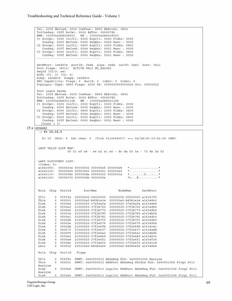
Troubleshooting and Technical Reference Guide - Volume 1
Ver: 2009 BbCred: 0000 ComFeat: 8800 BbRcvSz: 0800 TotConSeq: 00ff RoCat: 0002 EdTov: 000007d0 WWN: 100000a0b8028003 NN : 100000a0b8028003 C1 SvcOpt: 0000 IniCtl: 0000 RcpCtl: 0000 FldSz: 0000 ConSeq: 0000 EeCred: 0000 SeqExc: 0000 Resv : 0000 C2 SvcOpt: 8000 IniCtl: 0800 RcpCtl: 2000 FldSz: 0800 ConSeq: 00ff EeCred: 0004 SeqExc: 0001 Resv : 0000 C3 SvcOpt: 8000 IniCtl: 0000 RcpCtl: 0000 FldSz: 0800 ConSeq: 00ff EeCred: 0000 SeqExc: 0001 Resv : 0000 ----------------------------------- dstNPort: 1e6d934 portID: 0xda alpa: 0xda ourID: 0xe1 host: 0x11 Port flags: (4011) ACTIVE PRLI NO_EXLOGI SeqId (C2/3: ae) ACK0 (C1: 0) (C2: 0) ScbQ: 1e6d9c0 SuspQ: 1e6d9cc RNC Capability: Flags: 0 docId: 0 loRev: 0 hiRev: 0 FcpLogin--Type: 0800 Flags: 2000 PA: 0000000000000000 Svc: 00000022 Port Login Parms Ver: 2009 BbCred: 0000 ComFeat: 8800 BbRcvSz: 0800 TotConSeq: 00ff RoCat: 0002 EdTov: 000007d0 WWN: 100000a0b802116b NN : 100000a0b802116b C1 SvcOpt: 0000 IniCtl: 0000 RcpCtl: 0000 FldSz: 0000 ConSeq: 0000 EeCred: 0000 SeqExc: 0000 Resv : 0000 C2 SvcOpt: 8000 IniCtl: 0800 RcpCtl: 2000 FldSz: 0800 ConSeq: 00ff EeCred: 0004 SeqExc: 0001 Resv : 0000 C3 SvcOpt: 8000 IniCtl: 0000 RcpCtl: 0000 FldSz: 0800 ConSeq: 00ff EeCred: 0000 SeqExc: 0001 Resv : 0000 (Count = 3)
(5.x version) -> fc 10,10,3 fc 10 CHIP: 0 Dst chan: 0 (Tick 0114549057) ==> 04/28/05-19:02:09 (GMT) LAST VALID LOOP MAP: 0f 01 ef e8 - e4 e2 e1 e0 - dc da 55 3a - 72 4b 2e 02 LAST DISCOVERY LIST: <Index: 0> a164c0f0: 0000000e 00000002 000000ef 000000e8 *................* a164c100: 000000e4 000000e2 000000e1 000000e0 *................* a164c110: 000000dc 000000da 00000055 0000003a *........U...:...* a164c120: 00000072 0000004b 0000002e *r...K...........* Role Chip PortId PortWwn NodeWwn DstNPort Dflt 0 fffffe 00000000-00000000 00000000-00000000 a16347f0 This 0 000001 000000a0-b80b1e3e 000000a0-b80b1e3e a163486c Disk 0 0000e4 21000020-37a54afa 20000020-37a54afa a1634eb8 Disk 0 0000e0 21000020-37f2b760 20000020-37f2b760 a1634d44 Disk 0 0000ef 21000020-37f2b770 20000020-37f2b770 a1634fb0 Disk 0 00003a 21000020-37f2b780 20000020-37f2b780 a1634b54 Disk 0 0000e1 21000020-37f2b781 20000020-37f2b781 a1634dc0 Disk 0 00004b 21000020-37f2b7ff 20000020-37f2b7ff a16349e0 Disk 0 00002e 21000020-37f2e576 20000020-37f2e576 a1634964 Disk 0 0000da 21000020-37f2e5fb 20000020-37f2e5fb a1634c4c Disk 0 000072 21000020-37f2e637 20000020-37f2e637 a1634ad8 Disk 0 000055 21000020-37f2e6a3 20000020-37f2e6a3 a1634bd0 Disk 0 0000e2 21000020-37f2e6b9 20000020-37f2e6b9 a1634e3c Disk 0 0000e8 21000020-37f2e6f1 20000020-37f2e6f1 a1634f34 Disk 0 0000dc 21000020-37f2e6f2 20000020-37f2e6f2 a1634cc8 Lmir 0 000002 200100a0-b80b5e06 200000a0-b80b5e06 a16348e8 Role Chip PortId Flags Dflt 0 fffffe PRMT: 0x00000010 AbDsReq FLG: 0x00001000 Analyze This 0 000001 PRMT: 0x00000032 HddPort AbDsReq ShtSns FLG: 0x00001006 Plogi Prli Analyze Disk 0 0000e4 PRMT: 0x00000013 LogiIni HddPort AbDsReq FLG: 0x00001006 Plogi Prli Analyze Disk 0 0000e0 PRMT: 0x00000013 LogiIni HddPort AbDsReq FLG: 0x00001006 Plogi Prli
EngenioStorage Group LSI Logic, Inc.
69
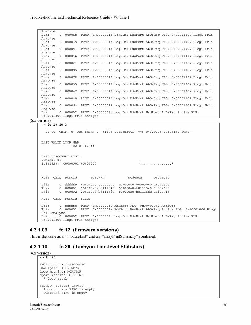
Troubleshooting and Technical Reference Guide - Volume 1
Analyze Disk 0 0000ef PRMT: 0x00000013 LogiIni HddPort AbDsReq FLG: 0x00001006 Plogi Prli Analyze Disk 0 00003a PRMT: 0x00000013 LogiIni HddPort AbDsReq FLG: 0x00001006 Plogi Prli Analyze Disk 0 0000e1 PRMT: 0x00000013 LogiIni HddPort AbDsReq FLG: 0x00001006 Plogi Prli Analyze Disk 0 00004b PRMT: 0x00000013 LogiIni HddPort AbDsReq FLG: 0x00001006 Plogi Prli Analyze Disk 0 00002e PRMT: 0x00000013 LogiIni HddPort AbDsReq FLG: 0x00001006 Plogi Prli Analyze Disk 0 0000da PRMT: 0x00000013 LogiIni HddPort AbDsReq FLG: 0x00001006 Plogi Prli Analyze Disk 0 000072 PRMT: 0x00000013 LogiIni HddPort AbDsReq FLG: 0x00001006 Plogi Prli Analyze Disk 0 000055 PRMT: 0x00000013 LogiIni HddPort AbDsReq FLG: 0x00001006 Plogi Prli Analyze Disk 0 0000e2 PRMT: 0x00000013 LogiIni HddPort AbDsReq FLG: 0x00001006 Plogi Prli Analyze Disk 0 0000e8 PRMT: 0x00000013 LogiIni HddPort AbDsReq FLG: 0x00001006 Plogi Prli Analyze Disk 0 0000dc PRMT: 0x00000013 LogiIni HddPort AbDsReq FLG: 0x00001006 Plogi Prli Analyze Lmir 0 000002 PRMT: 0x0000003b LogiIni HddPort HsdPort AbDsReq ShtSns FLG: 0x00001006 Plogi Prli Analyze
(6.x version) -> fc 10,10,3 fc 10 CHIP: 0 Dst chan: 0 (Tick 0001055401) ==> 04/29/05-00:08:30 (GMT) LAST VALID LOOP MAP: 02 01 02 ff LAST DISCOVERY LIST: <Index: 0> 1c431520: 00000001 00000002 *................* Role Chip PortId PortWwn NodeWwn DstNPort Dflt 0 fffffe 00000000-00000000 00000000-00000000 1c062d94 This 0 000001 200100a0-b8111546 200000a0-b8111546 1c0326f0 Lmir 0 000002 200100a0-b81116de 200000a0-b81116de 1af24718 Role Chip PortId Flags Dflt 0 fffffe PRMT: 0x00000010 AbDsReq FLG: 0x00001000 Analyze This 0 000001 PRMT: 0x0000003a HddPort HsdPort AbDsReq ShtSns FLG: 0x00001006 Plogi Prli Analyze Lmir 0 000002 PRMT: 0x0000003b LogiIni HddPort HsdPort AbDsReq ShtSns FLG: 0x00001006 Plogi Prli Analyze
4.3.1.09 fc 12 (firmware versions) This is the same as a “moduleList” and an “arrayPrintSummary” combined.
4.3.1.10 fc 20 (Tachyon Line-level Statistics) (4.x version)
-> fc 20 FMGR status: 0x98000000 GLM speed: 1062 Mb/s Loop machine: MONITOR Nport machine: OFFLINE * Loop estab Tachyon status: 0x1014 Inbound data FIFO is empty Outbound FIFO is empty
EngenioStorage Group LSI Logic, Inc.
70
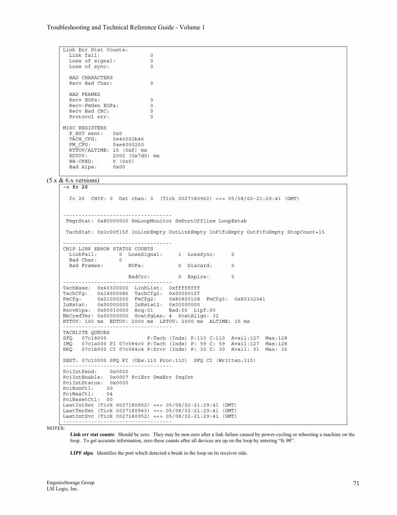
Troubleshooting and Technical Reference Guide - Volume 1
Link Err Stat Counts: Link fail: 0 Loss of signal: 0 Loss of sync: 0 BAD CHARACTERS Recv Bad Char: 0 BAD FRAMES Recv EOFa: 0 Recv-FmGen EOFa: 0 Recv Bad CRC: 0 Protocol err: 0 MISC REGISTERS P_BSY sent: 0x0 TACH_CFG: 0x40002b46 FM_CFG: 0xe4000200 RTTOV/ALTIME: 15 (0xf) ms EDTOV: 2000 (0x7d0) ms BB-CRED: 0 (0x0) Bad Alpa: 0x00
(5.x & 6.x versions) -> fc 20 fc 20 CHIP: 0 Dst chan: 0 (Tick 0027180962) ==> 05/08/02-21:29:41 (GMT) ----------------------------------- FmgrStat: 0x80000000 SmLoopMonitor SmPortOffline LoopEstab TachStat: 0x3c00f15f InLinkEmpty OutLinkEmpty InFifoEmpty OutFifoEmpty StopCount=15 ----------------------------------- CHIP LINK ERROR STATUS COUNTS LinkFail: 0 LossSignal: 1 LossSync: 0 Bad Char: 0 Bad Frames: EOFa: 0 Discard: 0 BadCrc: 0 Expire: 0 ----------------------------------- TachBase: 0x40300000 LinkList: 0xffffffff TachCfg: 0x18000086 TachCfg2: 0x000001ff FmCfg: 0x01000200 FmCfg2: 0x80800108 FmCfg3: 0x80332041 InRstat: 0x00000000 InRstat2: 0x00000000 RecvAlpa: 0x00010000 Acq:01 Bad:00 Lipf:00 BbCredTmr: 0x00000000 ScatPgLen: 4 ScatAlign: 32 RTTOV: 100 ms EDTOV: 2000 ms LPTOV: 2000 ms ALTIME: 15 ms ----------------------------------- TACHLITE QUEUES SFQ 07c18000 P:Tach (Indx) P:110 C:110 Avail:127 Max:128 IMQ 07c1a000 PI 07c084c0 P:Tach (Indx) P: 59 C: 59 Avail:127 Max:128 ERQ 07c1b000 CI 07c084c4 P:Drvr (Indx) P: 30 C: 30 Avail: 31 Max: 32 SEST: 07c10000 SFQ PI (Obs:110 Proc:110) SFQ CI (Written:110) ----------------------------------- PciIntPend: 0x0000 PciIntEnable: 0x0007 PciErr DmaErr ImqInt PciIntStatus: 0x0000 PciRomCtl: 00 PciMasCtl: 04 PciResetCtl: 00 LastIntSet (Tick 0027180952) ==> 05/08/02-21:29:41 (GMT) LastTmrSet (Tick 0027180943) ==> 05/08/02-21:29:41 (GMT) LastIntSvc (Tick 0027180952) ==> 05/08/02-21:29:41 (GMT) -----------------------------------
NOTES: Link err stat counts: Should be zero. They may be non-zero after a link failure caused by power-cycling or rebooting a machine on the loop. To get accurate information, zero these counts after all devices are up on the loop by entering “fc 90”. LIPF alpa: Identifies the port which detected a break in the loop on its receiver side.
EngenioStorage Group LSI Logic, Inc.
71
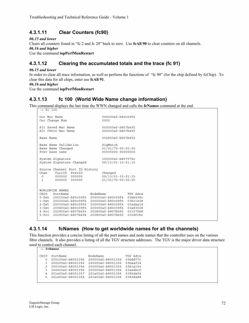
Troubleshooting and Technical Reference Guide - Volume 1
4.3.1.11 Clear Counters (fc90) 06.15 and lower Clears all counters found in “fc 2 and fc 20” back to zero. Use fcAll 90 to clear counters on all channels. 06.16 and higher Use the command iopPerfMonRestart
4.3.1.12 Clearing the accumulated totals and the trace (fc 91) 06.15 and lower In order to clear all trace information, as well as perform the functions of “fc 90” (for the chip defined by fcChip). To clear this data for all chips, enter use fcAll 91. 06.16 and higher Use the command iopPerfMonRestart
4.3.1.13 fc 100 (World Wide Name change information) This command displays the last time the WWN changed and calls the fcNames command at the end.
-> fc 100 Our Mac Name 000000a0-b80c09f6 Our Change Num 0002 Alt Saved Mac Name 000000a0-b807b492 Alt ChkIn Mac Name 000000a0-b807b492 Base Name 002800a0-b807b492 Base Name Validation SigMatch Base Name Changed 01/01/70-00:00:00 Prev base name 00000000-00000000 System Signature 100000a0-b807076c System Signature Changed 09/13/01-10:01:15 Source Channel Port ID History Chan CurrID PrevID Changed 0 000002 000000 09/13/01-10:01:15 1 000000 000000 01/01/70-00:00:00 WORLDWIDE NAMES CHIP PortName NodeName TGV Adrs 0-Dst 200100a0-b80c09f6 200000a0-b80c09f6 03bb438c 1-Dst 200200a0-b80c09f6 200000a0-b80c09f6 03b31e28 2-Dst 200300a0-b80c09f6 200000a0-b80c09f6 03adaa18 3-Dst 200400a0-b80c09f6 200000a0-b80c09f6 03a83608 4-Src 202900a0-b807b493 202800a0-b807b492 031575b8 5-Src 202900a0-b807b494 202800a0-b807b492 030dfcbc
4.3.1.14 fcNames (How to get worldwide names for all the channels) This function provides a concise listing of all the port names and node names that the controller uses on the various fibre channels. It also provides a listing of all the TGV structure addresses. The TGV is the major driver data structure used to control each channel.
-> fcNames CHIP PortName NodeName TGV Adrs 0 200100a0-b8001356 200000a0-b8001356 03bdd77c 1 200200a0-b8001356 200000a0-b8001356 03baaf34 2 200300a0-b8001356 200000a0-b8001356 03b1a144 3 200400a0-b8001356 200000a0-b8001356 03ae4bc0 4 201a00a0-b8001357 201a00a0-b8001356 0386da54 5 201a00a0-b8001358 201a00a0-b8001356 03838a88
EngenioStorage Group LSI Logic, Inc.
72
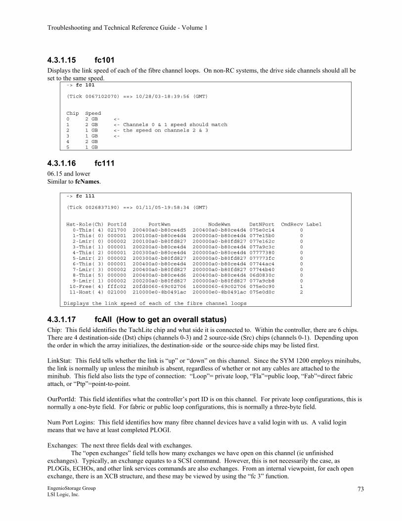
Troubleshooting and Technical Reference Guide - Volume 1
4.3.1.15 fc101 Displays the link speed of each of the fibre channel loops. On non-RC systems, the drive side channels should all be set to the same speed.
-> fc 101 (Tick 0067102070) ==> 10/28/03-18:39:56 (GMT) Chip Speed 0 2 GB <- 1 2 GB <- Channels 0 & 1 speed should match 2 1 GB <- the speed on channels 2 & 3 3 1 GB <- 4 2 GB 5 1 GB
4.3.1.16 fc111 06.15 and lower Similar to fcNames.
-> fc 111 (Tick 0026837190) ==> 01/11/05-19:58:34 (GMT) Hst-Role(Ch) PortId PortWwn NodeWwn DstNPort CmdRecv Label 0-This( 4) 021700 200400a0-b80ce4d5 200400a0-b80ce4d4 075e0c14 0 1-This( 0) 000001 200100a0-b80ce4d4 200000a0-b80ce4d4 077e15b0 0 2-Lmir( 0) 000002 200100a0-b80fd827 200000a0-b80fd827 077e162c 0 3-This( 1) 000001 200200a0-b80ce4d4 200000a0-b80ce4d4 077a9c3c 0 4-This( 2) 000001 200300a0-b80ce4d4 200000a0-b80ce4d4 07777380 0 5-Lmir( 2) 000002 200300a0-b80fd827 200000a0-b80fd827 077773fc 0 6-This( 3) 000001 200400a0-b80ce4d4 200000a0-b80ce4d4 07744ac4 0 7-Lmir( 3) 000002 200400a0-b80fd827 200000a0-b80fd827 07744b40 0 8-This( 5) 000000 200400a0-b80ce4d6 200400a0-b80ce4d4 06d0830c 0 9-Lmir( 1) 000002 200200a0-b80fd827 200000a0-b80fd827 077a9cb8 0 10-Free( 4) fffc02 20fd0060-69c02706 10000060-69c02706 075e0c90 1 11-Host( 4) 021000 210000e0-8b0491ac 200000e0-8b0491ac 075e0d0c 2 Displays the link speed of each of the fibre channel loops
4.3.1.17 fcAll (How to get an overall status) Chip: This field identifies the TachLite chip and what side it is connected to. Within the controller, there are 6 chips. There are 4 destination-side (Dst) chips (channels 0-3) and 2 source-side (Src) chips (channels 0-1). Depending upon the order in which the array initializes, the destination-side or the source-side chips may be listed first. LinkStat: This field tells whether the link is “up” or “down” on this channel. Since the SYM 1200 employs minihubs, the link is normally up unless the minihub is absent, regardless of whether or not any cables are attached to the minihub. This field also lists the type of connection: “Loop”= private loop, “Fla”=public loop, “Fab”=direct fabric attach, or “Ptp”=point-to-point. OurPortId: This field identifies what the controller’s port ID is on this channel. For private loop configurations, this is normally a one-byte field. For fabric or public loop configurations, this is normally a three-byte field. Num Port Logins: This field identifies how many fibre channel devices have a valid login with us. A valid login means that we have at least completed PLOGI. Exchanges: The next three fields deal with exchanges.
The “open exchanges” field tells how many exchanges we have open on this channel (ie unfinished exchanges). Typically, an exchange equates to a SCSI command. However, this is not necessarily the case, as PLOGIs, ECHOs, and other link services commands are also exchanges. From an internal viewpoint, for each open exchange, there is an XCB structure, and these may be viewed by using the “fc 3” function.
EngenioStorage Group LSI Logic, Inc.
73
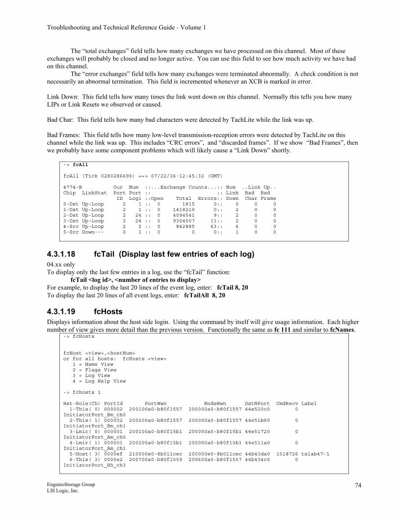
Troubleshooting and Technical Reference Guide - Volume 1
The “total exchanges” field tells how many exchanges we have processed on this channel. Most of these exchanges will probably be closed and no longer active. You can use this field to see how much activity we have had on this channel.
The “error exchanges” field tells how many exchanges were terminated abnormally. A check condition is not necessarily an abnormal termination. This field is incremented whenever an XCB is marked in error. Link Down: This field tells how many times the link went down on this channel. Normally this tells you how many LIPs or Link Resets we observed or caused. Bad Char: This field tells how many bad characters were detected by TachLite while the link was up. Bad Frames: This field tells how many low-level transmission-reception errors were detected by TachLite on this channel while the link was up. This includes “CRC errors”, and “discarded frames”. If we show “Bad Frames”, then we probably have some component problems which will likely cause a “Link Down” shortly.
-> fcAll fcAll (Tick 0280286690) ==> 07/22/36-12:45:32 (GMT) 4774-B Our Num ::...Exchange Counts...:: Num ..Link Up.. Chip LinkStat Port Port :: :: Link Bad Bad ID Logi ::Open Total Errors:: Down Char Frame 0-Dst Up-Loop 2 1 :: 0 1815 0:: 0 0 0 1-Dst Up-Loop 2 1 :: 0 1418210 0:: 2 0 0 2-Dst Up-Loop 2 24 :: 0 4094541 9:: 2 0 0 3-Dst Up-Loop 2 24 :: 0 9304507 11:: 2 0 0 4-Src Up-Loop 2 2 :: 0 842885 63:: 6 0 0 5-Src Down--- 0 1 :: 0 0 0:: 1 0 0
4.3.1.18 fcTail (Display last few entries of each log) 04.xx only To display only the last few entries in a log, use the “fcTail” function: fcTail <log id>, <number of entries to display> For example, to display the last 20 lines of the event log, enter: fcTail 8, 20 To display the last 20 lines of all event logs, enter: fcTailAll 8, 20
4.3.1.19 fcHosts Displays information about the host side login. Using the command by itself will give usage information. Each higher number of view gives more detail than the previous version. Functionally the same as fc 111 and similar to fcNames.
-> fcHosts fcHost <view>,<hostNum> or for all hosts: fcHosts <view> 1 = Name View 2 = Flags View 3 = Log View 4 = Log Help View -> fchosts 1 Hst-Role(Ch) PortId PortWwn NodeWwn DstNPort CmdRecv Label 1-This( 0) 000002 200100a0-b80f1557 200000a0-b80f1557 44e520c0 0 InitiatorPort_Bm_ch0 2-This( 1) 000002 200200a0-b80f1557 200000a0-b80f1557 44e51b60 0 InitiatorPort_Bm_ch1 3-Lmir( 0) 000001 200100a0-b80f15b1 200000a0-b80f15b1 44e51720 0 InitiatorPort_Am_ch0 4-Lmir( 1) 000001 200200a0-b80f15b1 200000a0-b80f15b1 44e511a0 0 InitiatorPort_Am_ch1 5-Host( 3) 0000ef 210000e0-8b011cec 200000e0-8b011cec 44b43da0 1518726 tslab47-1 6-This( 3) 0000e2 200700a0-b80f1559 200600a0-b80f1557 44b434c0 0 InitiatorPort_Bh_ch3
EngenioStorage Group LSI Logic, Inc.
74
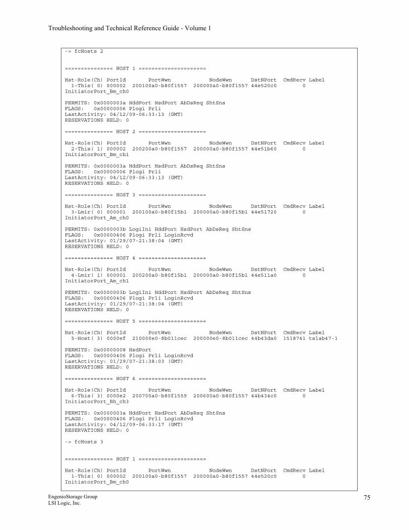
Troubleshooting and Technical Reference Guide - Volume 1
-> fcHosts 2 =============== HOST 1 ===================== Hst-Role(Ch) PortId PortWwn NodeWwn DstNPort CmdRecv Label 1-This( 0) 000002 200100a0-b80f1557 200000a0-b80f1557 44e520c0 0 InitiatorPort_Bm_ch0 PERMITS: 0x0000003a HddPort HsdPort AbDsReq ShtSns FLAGS: 0x00000006 Plogi Prli LastActivity: 04/12/09-06:33:13 (GMT) RESERVATIONS HELD: 0 =============== HOST 2 ===================== Hst-Role(Ch) PortId PortWwn NodeWwn DstNPort CmdRecv Label 2-This( 1) 000002 200200a0-b80f1557 200000a0-b80f1557 44e51b60 0 InitiatorPort_Bm_ch1 PERMITS: 0x0000003a HddPort HsdPort AbDsReq ShtSns FLAGS: 0x00000006 Plogi Prli LastActivity: 04/12/09-06:33:13 (GMT) RESERVATIONS HELD: 0 =============== HOST 3 ===================== Hst-Role(Ch) PortId PortWwn NodeWwn DstNPort CmdRecv Label 3-Lmir( 0) 000001 200100a0-b80f15b1 200000a0-b80f15b1 44e51720 0 InitiatorPort_Am_ch0 PERMITS: 0x0000003b LogiIni HddPort HsdPort AbDsReq ShtSns FLAGS: 0x00000406 Plogi Prli LoginRcvd LastActivity: 01/29/07-21:38:04 (GMT) RESERVATIONS HELD: 0 =============== HOST 4 ===================== Hst-Role(Ch) PortId PortWwn NodeWwn DstNPort CmdRecv Label 4-Lmir( 1) 000001 200200a0-b80f15b1 200000a0-b80f15b1 44e511a0 0 InitiatorPort_Am_ch1 PERMITS: 0x0000003b LogiIni HddPort HsdPort AbDsReq ShtSns FLAGS: 0x00000406 Plogi Prli LoginRcvd LastActivity: 01/29/07-21:38:04 (GMT) RESERVATIONS HELD: 0 =============== HOST 5 ===================== Hst-Role(Ch) PortId PortWwn NodeWwn DstNPort CmdRecv Label 5-Host( 3) 0000ef 210000e0-8b011cec 200000e0-8b011cec 44b43da0 1518741 tslab47-1 PERMITS: 0x00000008 HsdPort FLAGS: 0x00000406 Plogi Prli LoginRcvd LastActivity: 01/29/07-21:38:03 (GMT) RESERVATIONS HELD: 0 =============== HOST 6 ===================== Hst-Role(Ch) PortId PortWwn NodeWwn DstNPort CmdRecv Label 6-This( 3) 0000e2 200700a0-b80f1559 200600a0-b80f1557 44b434c0 0 InitiatorPort_Bh_ch3 PERMITS: 0x0000003a HddPort HsdPort AbDsReq ShtSns FLAGS: 0x00000406 Plogi Prli LoginRcvd LastActivity: 04/12/09-06:33:17 (GMT) RESERVATIONS HELD: 0 -> fcHosts 3 =============== HOST 1 ===================== Hst-Role(Ch) PortId PortWwn NodeWwn DstNPort CmdRecv Label 1-This( 0) 000002 200100a0-b80f1557 200000a0-b80f1557 44e520c0 0 InitiatorPort_Bm_ch0
EngenioStorage Group LSI Logic, Inc.
75
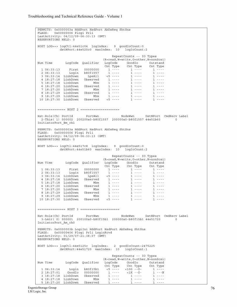
Troubleshooting and Technical Reference Guide - Volume 1
PERMITS: 0x0000003a HddPort HsdPort AbDsReq ShtSns FLAGS: 0x00000006 Plogi Prli LastActivity: 04/12/09-06:33:13 (GMT) RESERVATIONS HELD: 0 HOST LOG==> logCtl:44e51c04 logIndex: 9 goodIoCount:0 dstNPort:44e520c0 maxIndex: 10 logIoCount:2 RepeatCounts -- IO Types (R=read,W=write,O=other,N=nonScsi) Num Time LogCode Qualifier LogCode GoodIo Outstand Cnt Type Cnt Type Cnt Type 1 06:33:13 First 00000000 1 ---- 1 ---- 1 ---- 2 06:33:13 Login b80f1557 1 ---- 1 ---- 1 ---- 3 06:33:14 LinkDown LpeAll <5 ---- 1 ---- 1 ---- 4 18:27:18 LinkDown Observed 1 ---- 1 ---- 1 ---- 5 18:27:18 LinkDown Mhm 1 ---- 1 ---- 1 ---- 6 18:27:20 LinkDown Observed 1 ---- 1 ---- 1 ---- 7 18:27:20 LinkDown Mhm 1 ---- 1 ---- 1 ---- 8 18:27:29 LinkDown Observed 1 ---- 1 ---- 1 ---- 9 18:27:29 LinkDown Mhm 1 ---- 1 ---- 1 ---- 10 18:27:30 LinkDown Observed <5 ---- 1 ---- 1 ---- =============== HOST 2 ===================== Hst-Role(Ch) PortId PortWwn NodeWwn DstNPort CmdRecv Label 2-This( 1) 000002 200200a0-b80f1557 200000a0-b80f1557 44e51b60 0 InitiatorPort_Bm_ch1 PERMITS: 0x0000003a HddPort HsdPort AbDsReq ShtSns FLAGS: 0x00000006 Plogi Prli LastActivity: 04/12/09-06:33:13 (GMT) RESERVATIONS HELD: 0 HOST LOG==> logCtl:44e517c8 logIndex: 9 goodIoCount:0 dstNPort:44e51b60 maxIndex: 10 logIoCount:2 RepeatCounts -- IO Types (R=read,W=write,O=other,N=nonScsi) Num Time LogCode Qualifier LogCode GoodIo Outstand Cnt Type Cnt Type Cnt Type 1 06:33:13 First 00000000 1 ---- 1 ---- 1 ---- 2 06:33:13 Login b80f1557 1 ---- 1 ---- 1 ---- 3 06:33:14 LinkDown LpeAll <5 ---- 1 ---- 1 ---- 4 18:27:18 LinkDown Observed 1 ---- 1 ---- 1 ---- 5 18:27:18 LinkDown Mhm 1 ---- 1 ---- 1 ---- 6 18:27:20 LinkDown Observed 1 ---- 1 ---- 1 ---- 7 18:27:20 LinkDown Mhm 1 ---- 1 ---- 1 ---- 8 18:27:29 LinkDown Observed 1 ---- 1 ---- 1 ---- 9 18:27:29 LinkDown Mhm 1 ---- 1 ---- 1 ---- 10 18:27:30 LinkDown Observed <5 ---- 1 ---- 1 ---- =============== HOST 3 ===================== Hst-Role(Ch) PortId PortWwn NodeWwn DstNPort CmdRecv Label 3-Lmir( 0) 000001 200100a0-b80f15b1 200000a0-b80f15b1 44e51720 0 InitiatorPort_Am_ch0 PERMITS: 0x0000003b LogiIni HddPort HsdPort AbDsReq ShtSns FLAGS: 0x00000406 Plogi Prli LoginRcvd LastActivity: 01/29/07-21:38:07 (GMT) RESERVATIONS HELD: 0 HOST LOG==> logCtl:44e5125c logIndex: 2 goodIoCount:2475225 dstNPort:44e51720 maxIndex: 10 logIoCount:1 RepeatCounts -- IO Types (R=read,W=write,O=other,N=nonScsi) Num Time LogCode Qualifier LogCode GoodIo Outstand Cnt Type Cnt Type Cnt Type 1 06:33:14 Login b80f15b1 <5 ---- <100 --O- 1 ---- 2 18:27:01 GoodIo 00000000 1 ---- <1K --O- 1 ---N 3 18:27:18 LinkDown Observed 1 ---- 1 ---- 1 ---- 4 18:27:18 LinkDown Mhm 1 ---- 1 ---- 1 ---- 5 18:27:20 LinkDown Observed 1 ---- 1 ---- 1 ----
EngenioStorage Group LSI Logic, Inc.
76
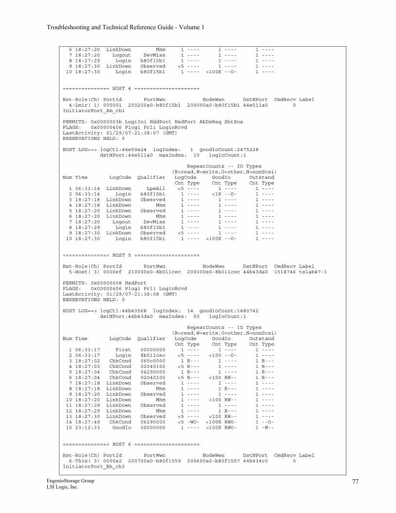
Troubleshooting and Technical Reference Guide - Volume 1
6 18:27:20 LinkDown Mhm 1 ---- 1 ---- 1 ---- 7 18:27:20 Logout DevMiss 1 ---- 1 ---- 1 ---- 8 18:27:29 Login b80f15b1 1 ---- 1 ---- 1 ---- 9 18:27:30 LinkDown Observed <5 ---- 1 ---- 1 ---- 10 18:27:30 Login b80f15b1 1 ---- >100K --O- 1 ---- =============== HOST 4 ===================== Hst-Role(Ch) PortId PortWwn NodeWwn DstNPort CmdRecv Label 4-Lmir( 1) 000001 200200a0-b80f15b1 200000a0-b80f15b1 44e511a0 0 InitiatorPort_Am_ch1 PERMITS: 0x0000003b LogiIni HddPort HsdPort AbDsReq ShtSns FLAGS: 0x00000406 Plogi Prli LoginRcvd LastActivity: 01/29/07-21:38:07 (GMT) RESERVATIONS HELD: 0 HOST LOG==> logCtl:44e50e24 logIndex: 1 goodIoCount:2475228 dstNPort:44e511a0 maxIndex: 10 logIoCount:1 RepeatCounts -- IO Types (R=read,W=write,O=other,N=nonScsi) Num Time LogCode Qualifier LogCode GoodIo Outstand Cnt Type Cnt Type Cnt Type 1 06:33:14 LinkDown LpeAll <5 ---- 1 ---- 1 ---- 2 06:33:14 Login b80f15b1 1 ---- <1K --O- 1 ---- 3 18:27:18 LinkDown Observed 1 ---- 1 ---- 1 ---- 4 18:27:18 LinkDown Mhm 1 ---- 1 ---- 1 ---- 5 18:27:20 LinkDown Observed 1 ---- 1 ---- 1 ---- 6 18:27:20 LinkDown Mhm 1 ---- 1 ---- 1 ---- 7 18:27:20 Logout DevMiss 1 ---- 1 ---- 1 ---- 8 18:27:29 Login b80f15b1 1 ---- 1 ---- 1 ---- 9 18:27:30 LinkDown Observed <5 ---- 1 ---- 1 ---- 10 18:27:30 Login b80f15b1 1 ---- >100K --O- 1 ---- =============== HOST 5 ===================== Hst-Role(Ch) PortId PortWwn NodeWwn DstNPort CmdRecv Label 5-Host( 3) 0000ef 210000e0-8b011cec 200000e0-8b011cec 44b43da0 1518746 tslab47-1 PERMITS: 0x00000008 HsdPort FLAGS: 0x00000406 Plogi Prli LoginRcvd LastActivity: 01/29/07-21:38:08 (GMT) RESERVATIONS HELD: 0 HOST LOG==> logCtl:44b43568 logIndex: 14 goodIoCount:1480742 dstNPort:44b43da0 maxIndex: 50 logIoCount:1 RepeatCounts -- IO Types (R=read,W=write,O=other,N=nonScsi) Num Time LogCode Qualifier LogCode GoodIo Outstand Cnt Type Cnt Type Cnt Type 1 06:33:17 First 00000000 1 ---- 1 ---- 1 ---- 2 06:33:17 Login 8b011cec <5 ---- <100 --O- 1 ---- 3 18:27:02 ChkCond 060c0000 1 R--- 1 ---- 1 R--- 4 18:27:03 ChkCond 02040100 <5 R--- 1 ---- 1 R--- 5 18:27:04 ChkCond 06290000 1 R--- 1 ---- 1 R--- 6 18:27:04 ChkCond 02040100 <5 R--- <100 RW-- 1 R--- 7 18:27:18 LinkDown Observed 1 ---- 1 ---- 1 ---- 8 18:27:18 LinkDown Mhm 1 ---- 1 R--- 1 ---- 9 18:27:20 LinkDown Observed 1 ---- 1 ---- 1 ---- 10 18:27:20 LinkDown Mhm 1 ---- <100 RW-- 1 ---- 11 18:27:29 LinkDown Observed 1 ---- 1 ---- 1 ---- 12 18:27:29 LinkDown Mhm 1 ---- 1 R--- 1 ---- 13 18:27:30 LinkDown Observed <5 ---- <100 RW-- 1 ---- 14 18:27:49 ChkCond 06290000 <5 -WO- <100K RWO- 1 --O- 15 23:12:33 GoodIo 00000000 1 ---- >100K RWO- 1 -W-- =============== HOST 6 ===================== Hst-Role(Ch) PortId PortWwn NodeWwn DstNPort CmdRecv Label 6-This( 3) 0000e2 200700a0-b80f1559 200600a0-b80f1557 44b434c0 0 InitiatorPort_Bh_ch3
EngenioStorage Group LSI Logic, Inc.
77
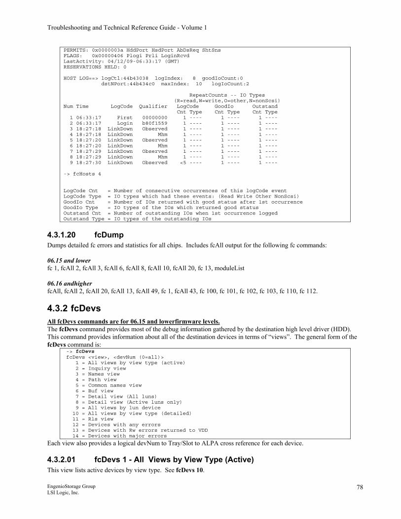
Troubleshooting and Technical Reference Guide - Volume 1
PERMITS: 0x0000003a HddPort HsdPort AbDsReq ShtSns FLAGS: 0x00000406 Plogi Prli LoginRcvd LastActivity: 04/12/09-06:33:17 (GMT) RESERVATIONS HELD: 0 HOST LOG==> logCtl:44b43038 logIndex: 8 goodIoCount:0 dstNPort:44b434c0 maxIndex: 10 logIoCount:2 RepeatCounts -- IO Types (R=read,W=write,O=other,N=nonScsi) Num Time LogCode Qualifier LogCode GoodIo Outstand Cnt Type Cnt Type Cnt Type 1 06:33:17 First 00000000 1 ---- 1 ---- 1 ---- 2 06:33:17 Login b80f1559 1 ---- 1 ---- 1 ---- 3 18:27:18 LinkDown Observed 1 ---- 1 ---- 1 ---- 4 18:27:18 LinkDown Mhm 1 ---- 1 ---- 1 ---- 5 18:27:20 LinkDown Observed 1 ---- 1 ---- 1 ---- 6 18:27:20 LinkDown Mhm 1 ---- 1 ---- 1 ---- 7 18:27:29 LinkDown Observed 1 ---- 1 ---- 1 ---- 8 18:27:29 LinkDown Mhm 1 ---- 1 ---- 1 ---- 9 18:27:30 LinkDown Observed <5 ---- 1 ---- 1 ---- -> fcHosts 4 LogCode Cnt = Number of consecutive occurrences of this logCode event LogCode Type = IO types which had these events: (Read Write Other NonScsi) GoodIo Cnt = Number of IOs returned with good status after 1st occurrence GoodIo Type = IO types of the IOs which returned good status Outstand Cnt = Number of outstanding IOs when 1st occurrence logged Outstand Type = IO types of the outstanding IOs
4.3.1.20 fcDump Dumps detailed fc errors and statistics for all chips. Includes fcAll output for the following fc commands: 06.15 and lower fc 1, fcAll 2, fcAll 3, fcAll 6, fcAll 8, fcAll 10, fcAll 20, fc 13, moduleList 06.16 andhigher fcAll, fcAll 2, fcAll 20, fcAll 13, fcAll 49, fc 1, fcAll 43, fc 100, fc 101, fc 102, fc 103, fc 110, fc 112.
4.3.2 fcDevs All fcDevs commands are for 06.15 and lowerfirmware levels. The fcDevs command provides most of the debug information gathered by the destination high level driver (HDD). This command provides information about all of the destination devices in terms of “views”. The general form of the fcDevs command is:
-> fcDevs fcDevs <view>, <devNum (0=all)> 1 = All views by view type (active) 2 = Inquiry view 3 = Names view 4 = Path view 5 = Common names view 6 = Buf view 7 = Detail view (All luns) 8 = Detail view (Active luns only) 9 = All views by lun device 10 = All views by view type (detailed) 11 = Rls view 12 = Devices with any errors 13 = Devices with Rw errors returned to VDD 14 = Devices with major errors
Each view also provides a logical devNum to Tray/Slot to ALPA cross reference for each device.
4.3.2.01 fcDevs 1 - All Views by View Type (Active) This view lists active devices by view type. See fcDevs 10.
EngenioStorage Group LSI Logic, Inc.
78
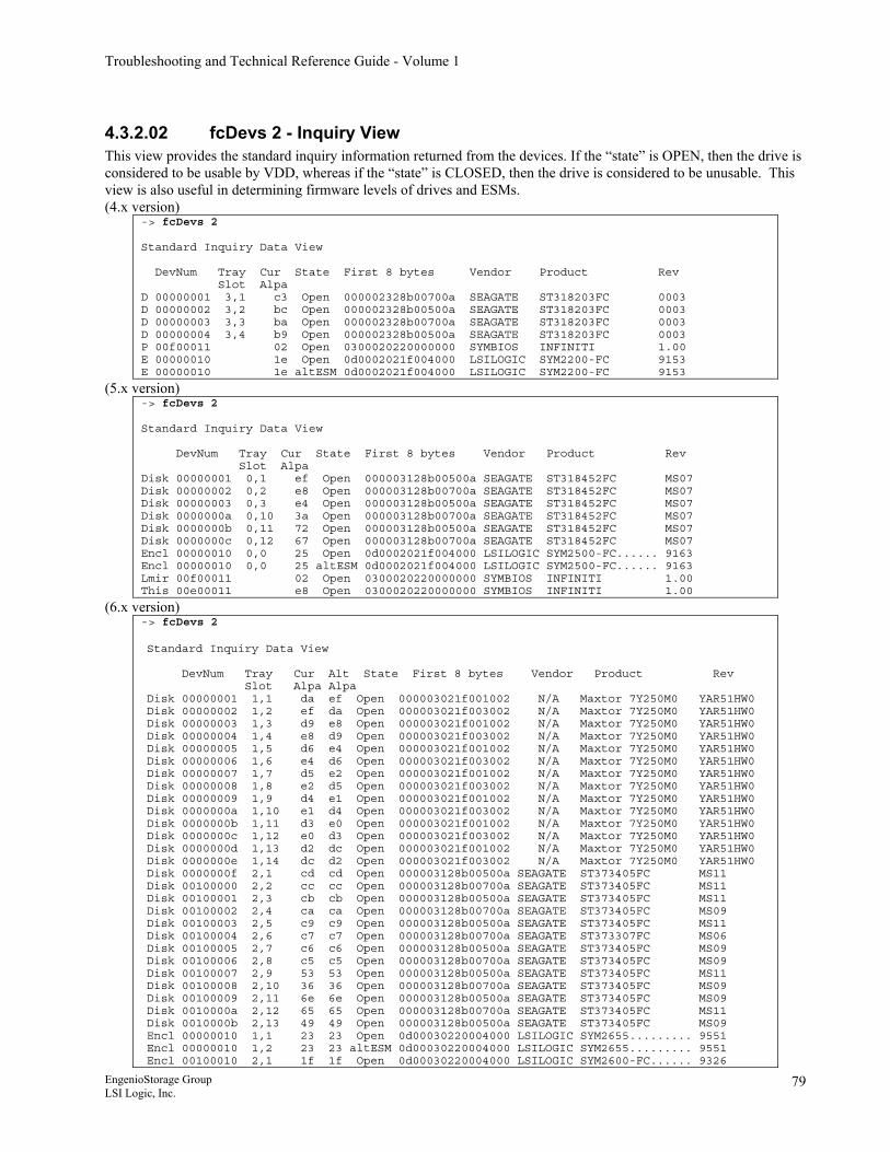
Troubleshooting and Technical Reference Guide - Volume 1
4.3.2.02 fcDevs 2 - Inquiry View This view provides the standard inquiry information returned from the devices. If the “state” is OPEN, then the drive is considered to be usable by VDD, whereas if the “state” is CLOSED, then the drive is considered to be unusable. This view is also useful in determining firmware levels of drives and ESMs. (4.x version)
-> fcDevs 2 Standard Inquiry Data View DevNum Tray Cur State First 8 bytes Vendor Product Rev Slot Alpa D 00000001 3,1 c3 Open 000002328b00700a SEAGATE ST318203FC 0003 D 00000002 3,2 bc Open 000002328b00500a SEAGATE ST318203FC 0003 D 00000003 3,3 ba Open 000002328b00700a SEAGATE ST318203FC 0003 D 00000004 3,4 b9 Open 000002328b00500a SEAGATE ST318203FC 0003 P 00f00011 02 Open 0300020220000000 SYMBIOS INFINITI 1.00 E 00000010 1e Open 0d0002021f004000 LSILOGIC SYM2200-FC 9153 E 00000010 1e altESM 0d0002021f004000 LSILOGIC SYM2200-FC 9153
(5.x version) -> fcDevs 2 Standard Inquiry Data View DevNum Tray Cur State First 8 bytes Vendor Product Rev Slot Alpa Disk 00000001 0,1 ef Open 000003128b00500a SEAGATE ST318452FC MS07 Disk 00000002 0,2 e8 Open 000003128b00700a SEAGATE ST318452FC MS07 Disk 00000003 0,3 e4 Open 000003128b00500a SEAGATE ST318452FC MS07 Disk 0000000a 0,10 3a Open 000003128b00700a SEAGATE ST318452FC MS07 Disk 0000000b 0,11 72 Open 000003128b00500a SEAGATE ST318452FC MS07 Disk 0000000c 0,12 67 Open 000003128b00700a SEAGATE ST318452FC MS07 Encl 00000010 0,0 25 Open 0d0002021f004000 LSILOGIC SYM2500-FC...... 9163 Encl 00000010 0,0 25 altESM 0d0002021f004000 LSILOGIC SYM2500-FC...... 9163 Lmir 00f00011 02 Open 0300020220000000 SYMBIOS INFINITI 1.00 This 00e00011 e8 Open 0300020220000000 SYMBIOS INFINITI 1.00
(6.x version) -> fcDevs 2 Standard Inquiry Data View DevNum Tray Cur Alt State First 8 bytes Vendor Product Rev Slot Alpa Alpa Disk 00000001 1,1 da ef Open 000003021f001002 N/A Maxtor 7Y250M0 YAR51HW0 Disk 00000002 1,2 ef da Open 000003021f003002 N/A Maxtor 7Y250M0 YAR51HW0 Disk 00000003 1,3 d9 e8 Open 000003021f001002 N/A Maxtor 7Y250M0 YAR51HW0 Disk 00000004 1,4 e8 d9 Open 000003021f003002 N/A Maxtor 7Y250M0 YAR51HW0 Disk 00000005 1,5 d6 e4 Open 000003021f001002 N/A Maxtor 7Y250M0 YAR51HW0 Disk 00000006 1,6 e4 d6 Open 000003021f003002 N/A Maxtor 7Y250M0 YAR51HW0 Disk 00000007 1,7 d5 e2 Open 000003021f001002 N/A Maxtor 7Y250M0 YAR51HW0 Disk 00000008 1,8 e2 d5 Open 000003021f003002 N/A Maxtor 7Y250M0 YAR51HW0 Disk 00000009 1,9 d4 e1 Open 000003021f001002 N/A Maxtor 7Y250M0 YAR51HW0 Disk 0000000a 1,10 e1 d4 Open 000003021f003002 N/A Maxtor 7Y250M0 YAR51HW0 Disk 0000000b 1,11 d3 e0 Open 000003021f001002 N/A Maxtor 7Y250M0 YAR51HW0 Disk 0000000c 1,12 e0 d3 Open 000003021f003002 N/A Maxtor 7Y250M0 YAR51HW0 Disk 0000000d 1,13 d2 dc Open 000003021f001002 N/A Maxtor 7Y250M0 YAR51HW0 Disk 0000000e 1,14 dc d2 Open 000003021f003002 N/A Maxtor 7Y250M0 YAR51HW0 Disk 0000000f 2,1 cd cd Open 000003128b00500a SEAGATE ST373405FC MS11 Disk 00100000 2,2 cc cc Open 000003128b00700a SEAGATE ST373405FC MS11 Disk 00100001 2,3 cb cb Open 000003128b00500a SEAGATE ST373405FC MS11 Disk 00100002 2,4 ca ca Open 000003128b00700a SEAGATE ST373405FC MS09 Disk 00100003 2,5 c9 c9 Open 000003128b00500a SEAGATE ST373405FC MS11 Disk 00100004 2,6 c7 c7 Open 000003128b00700a SEAGATE ST373307FC MS06 Disk 00100005 2,7 c6 c6 Open 000003128b00500a SEAGATE ST373405FC MS09 Disk 00100006 2,8 c5 c5 Open 000003128b00700a SEAGATE ST373405FC MS09 Disk 00100007 2,9 53 53 Open 000003128b00500a SEAGATE ST373405FC MS11 Disk 00100008 2,10 36 36 Open 000003128b00700a SEAGATE ST373405FC MS09 Disk 00100009 2,11 6e 6e Open 000003128b00500a SEAGATE ST373405FC MS09 Disk 0010000a 2,12 65 65 Open 000003128b00700a SEAGATE ST373405FC MS11 Disk 0010000b 2,13 49 49 Open 000003128b00500a SEAGATE ST373405FC MS09 Encl 00000010 1,1 23 23 Open 0d00030220004000 LSILOGIC SYM2655......... 9551 Encl 00000010 1,2 23 23 altESM 0d00030220004000 LSILOGIC SYM2655......... 9551 Encl 00100010 2,1 1f 1f Open 0d00030220004000 LSILOGIC SYM2600-FC...... 9326
EngenioStorage Group LSI Logic, Inc.
79
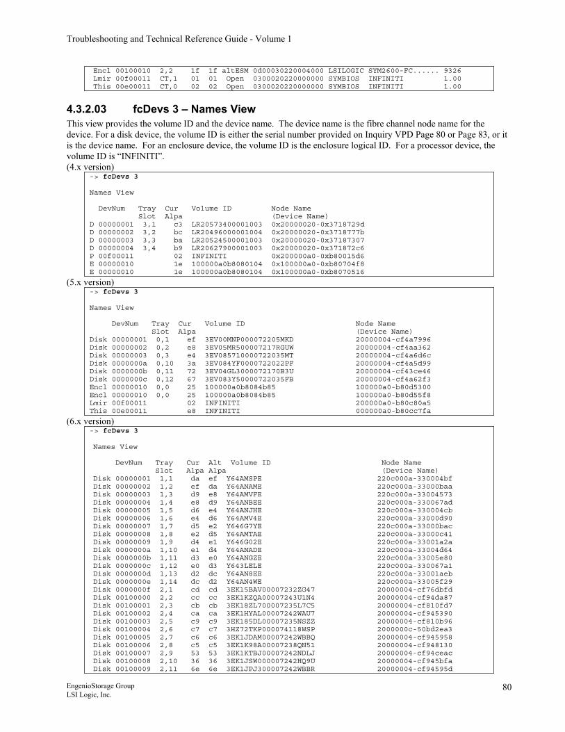
Troubleshooting and Technical Reference Guide - Volume 1
Encl 00100010 2,2 1f 1f altESM 0d00030220004000 LSILOGIC SYM2600-FC...... 9326 Lmir 00f00011 CT,1 01 01 Open 0300020220000000 SYMBIOS INFINITI 1.00 This 00e00011 CT,0 02 02 Open 0300020220000000 SYMBIOS INFINITI 1.00
4.3.2.03 fcDevs 3 – Names View This view provides the volume ID and the device name. The device name is the fibre channel node name for the device. For a disk device, the volume ID is either the serial number provided on Inquiry VPD Page 80 or Page 83, or it is the device name. For an enclosure device, the volume ID is the enclosure logical ID. For a processor device, the volume ID is “INFINITI”. (4.x version)
-> fcDevs 3 Names View DevNum Tray Cur Volume ID Node Name Slot Alpa (Device Name) D 00000001 3,1 c3 LR20573400001003 0x20000020-0x3718729d D 00000002 3,2 bc LR20496000001004 0x20000020-0x3718777b D 00000003 3,3 ba LR20524500001003 0x20000020-0x37187307 D 00000004 3,4 b9 LR20627900001003 0x20000020-0x371872c6 P 00f00011 02 INFINITI 0x200000a0-0xb80015d6 E 00000010 1e 100000a0b8080104 0x100000a0-0xb80704f8 E 00000010 1e 100000a0b8080104 0x100000a0-0xb8070516
(5.x version) -> fcDevs 3 Names View DevNum Tray Cur Volume ID Node Name Slot Alpa (Device Name) Disk 00000001 0,1 ef 3EV00MNP000072205MKD 20000004-cf4a7996 Disk 00000002 0,2 e8 3EV05MR500007217RGUW 20000004-cf4aa362 Disk 00000003 0,3 e4 3EV085710000722035MT 20000004-cf4a6d6c Disk 0000000a 0,10 3a 3EV084YF0000722022PF 20000004-cf4a5d99 Disk 0000000b 0,11 72 3EV04GL3000072170B3U 20000004-cf43ce46 Disk 0000000c 0,12 67 3EV083Y50000722035FB 20000004-cf4a62f3 Encl 00000010 0,0 25 100000a0b8084b85 100000a0-b80d5300 Encl 00000010 0,0 25 100000a0b8084b85 100000a0-b80d55f8 Lmir 00f00011 02 INFINITI 200000a0-b80c80a5 This 00e00011 e8 INFINITI 000000a0-b80cc7fa
(6.x version) -> fcDevs 3 Names View DevNum Tray Cur Alt Volume ID Node Name Slot Alpa Alpa (Device Name) Disk 00000001 1,1 da ef Y64AMSPE 220c000a-330004bf Disk 00000002 1,2 ef da Y64ANAME 220c000a-33000baa Disk 00000003 1,3 d9 e8 Y64AMVFE 220c000a-33004573 Disk 00000004 1,4 e8 d9 Y64ANBEE 220c000a-330067ad Disk 00000005 1,5 d6 e4 Y64ANJHE 220c000a-330004cb Disk 00000006 1,6 e4 d6 Y64AMV4E 220c000a-33000d90 Disk 00000007 1,7 d5 e2 Y646G7YE 220c000a-33000bac Disk 00000008 1,8 e2 d5 Y64AMTAE 220c000a-33000c41 Disk 00000009 1,9 d4 e1 Y646G02E 220c000a-33001a2a Disk 0000000a 1,10 e1 d4 Y64ANADE 220c000a-33004d64 Disk 0000000b 1,11 d3 e0 Y64ANGZE 220c000a-33005e80 Disk 0000000c 1,12 e0 d3 Y643LELE 220c000a-330067a1 Disk 0000000d 1,13 d2 dc Y64AN8EE 220c000a-33001aeb Disk 0000000e 1,14 dc d2 Y64AN4WE 220c000a-33005f29 Disk 0000000f 2,1 cd cd 3EK15BAV00007232ZG47 20000004-cf76dbfd Disk 00100000 2,2 cc cc 3EK1KZQA00007243U1N4 20000004-cf94da87 Disk 00100001 2,3 cb cb 3EK18ZL700007235L7C5 20000004-cf810fd7 Disk 00100002 2,4 ca ca 3EK1HYAL00007242WAU7 20000004-cf945390 Disk 00100003 2,5 c9 c9 3EK185DL00007235NSZZ 20000004-cf810b96 Disk 00100004 2,6 c7 c7 3HZ72TKP000074118WSP 2000000c-50bd2ea3 Disk 00100005 2,7 c6 c6 3EK1JDAM00007242WBBQ 20000004-cf945958 Disk 00100006 2,8 c5 c5 3EK1K98A00007238QN51 20000004-cf948130 Disk 00100007 2,9 53 53 3EK1KTBJ00007242NDLJ 20000004-cf94ceac Disk 00100008 2,10 36 36 3EK1JSW000007242HQ9U 20000004-cf945bfa Disk 00100009 2,11 6e 6e 3EK1JPJ300007242WBBR 20000004-cf94595d
EngenioStorage Group LSI Logic, Inc.
80
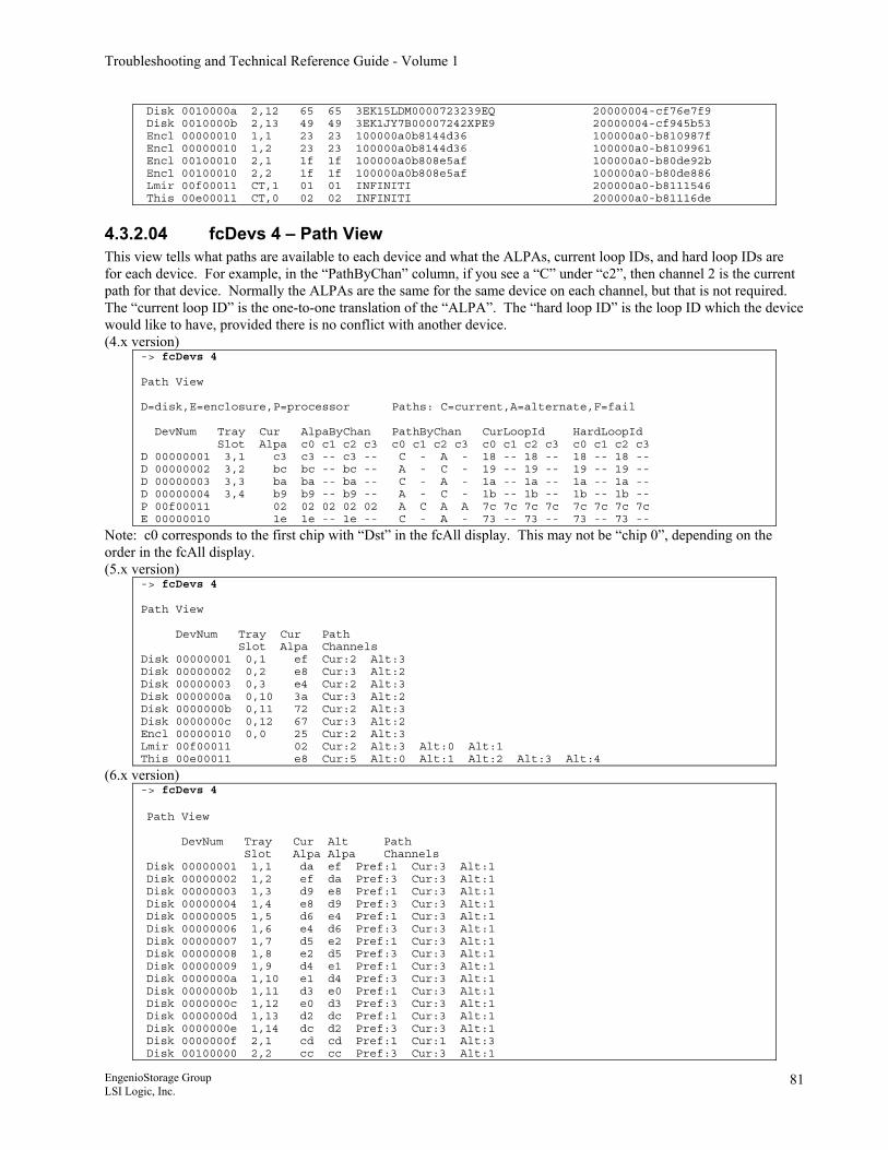
Troubleshooting and Technical Reference Guide - Volume 1
Disk 0010000a 2,12 65 65 3EK15LDM0000723239EQ 20000004-cf76e7f9 Disk 0010000b 2,13 49 49 3EK1JY7B00007242XPE9 20000004-cf945b53 Encl 00000010 1,1 23 23 100000a0b8144d36 100000a0-b810987f Encl 00000010 1,2 23 23 100000a0b8144d36 100000a0-b8109961 Encl 00100010 2,1 1f 1f 100000a0b808e5af 100000a0-b80de92b Encl 00100010 2,2 1f 1f 100000a0b808e5af 100000a0-b80de886 Lmir 00f00011 CT,1 01 01 INFINITI 200000a0-b8111546 This 00e00011 CT,0 02 02 INFINITI 200000a0-b81116de
4.3.2.04 fcDevs 4 – Path View This view tells what paths are available to each device and what the ALPAs, current loop IDs, and hard loop IDs are for each device. For example, in the “PathByChan” column, if you see a “C” under “c2”, then channel 2 is the current path for that device. Normally the ALPAs are the same for the same device on each channel, but that is not required. The “current loop ID” is the one-to-one translation of the “ALPA”. The “hard loop ID” is the loop ID which the device would like to have, provided there is no conflict with another device. (4.x version)
-> fcDevs 4 Path View D=disk,E=enclosure,P=processor Paths: C=current,A=alternate,F=fail DevNum Tray Cur AlpaByChan PathByChan CurLoopId HardLoopId Slot Alpa c0 c1 c2 c3 c0 c1 c2 c3 c0 c1 c2 c3 c0 c1 c2 c3 D 00000001 3,1 c3 c3 -- c3 -- C - A - 18 -- 18 -- 18 -- 18 -- D 00000002 3,2 bc bc -- bc -- A - C - 19 -- 19 -- 19 -- 19 -- D 00000003 3,3 ba ba -- ba -- C - A - 1a -- 1a -- 1a -- 1a -- D 00000004 3,4 b9 b9 -- b9 -- A - C - 1b -- 1b -- 1b -- 1b -- P 00f00011 02 02 02 02 02 A C A A 7c 7c 7c 7c 7c 7c 7c 7c E 00000010 1e 1e -- 1e -- C - A - 73 -- 73 -- 73 -- 73 --
Note: c0 corresponds to the first chip with “Dst” in the fcAll display. This may not be “chip 0”, depending on the order in the fcAll display. (5.x version)
-> fcDevs 4 Path View DevNum Tray Cur Path Slot Alpa Channels Disk 00000001 0,1 ef Cur:2 Alt:3 Disk 00000002 0,2 e8 Cur:3 Alt:2 Disk 00000003 0,3 e4 Cur:2 Alt:3 Disk 0000000a 0,10 3a Cur:3 Alt:2 Disk 0000000b 0,11 72 Cur:2 Alt:3 Disk 0000000c 0,12 67 Cur:3 Alt:2 Encl 00000010 0,0 25 Cur:2 Alt:3 Lmir 00f00011 02 Cur:2 Alt:3 Alt:0 Alt:1 This 00e00011 e8 Cur:5 Alt:0 Alt:1 Alt:2 Alt:3 Alt:4
(6.x version) -> fcDevs 4 Path View DevNum Tray Cur Alt Path Slot Alpa Alpa Channels Disk 00000001 1,1 da ef Pref:1 Cur:3 Alt:1 Disk 00000002 1,2 ef da Pref:3 Cur:3 Alt:1 Disk 00000003 1,3 d9 e8 Pref:1 Cur:3 Alt:1 Disk 00000004 1,4 e8 d9 Pref:3 Cur:3 Alt:1 Disk 00000005 1,5 d6 e4 Pref:1 Cur:3 Alt:1 Disk 00000006 1,6 e4 d6 Pref:3 Cur:3 Alt:1 Disk 00000007 1,7 d5 e2 Pref:1 Cur:3 Alt:1 Disk 00000008 1,8 e2 d5 Pref:3 Cur:3 Alt:1 Disk 00000009 1,9 d4 e1 Pref:1 Cur:3 Alt:1 Disk 0000000a 1,10 e1 d4 Pref:3 Cur:3 Alt:1 Disk 0000000b 1,11 d3 e0 Pref:1 Cur:3 Alt:1 Disk 0000000c 1,12 e0 d3 Pref:3 Cur:3 Alt:1 Disk 0000000d 1,13 d2 dc Pref:1 Cur:3 Alt:1 Disk 0000000e 1,14 dc d2 Pref:3 Cur:3 Alt:1 Disk 0000000f 2,1 cd cd Pref:1 Cur:1 Alt:3 Disk 00100000 2,2 cc cc Pref:3 Cur:3 Alt:1
EngenioStorage Group LSI Logic, Inc.
81
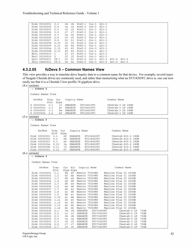
Troubleshooting and Technical Reference Guide - Volume 1
Disk 00100001 2,3 cb cb Pref:1 Cur:1 Alt:3 Disk 00100002 2,4 ca ca Pref:3 Cur:3 Alt:1 Disk 00100003 2,5 c9 c9 Pref:1 Cur:1 Alt:3 Disk 00100004 2,6 c7 c7 Pref:3 Cur:3 Alt:1 Disk 00100005 2,7 c6 c6 Pref:1 Cur:1 Alt:3 Disk 00100006 2,8 c5 c5 Pref:3 Cur:3 Alt:1 Disk 00100007 2,9 53 53 Pref:1 Cur:1 Alt:3 Disk 00100008 2,10 36 36 Pref:3 Cur:3 Alt:1 Disk 00100009 2,11 6e 6e Pref:1 Cur:1 Alt:3 Disk 0010000a 2,12 65 65 Pref:3 Cur:3 Alt:1 Disk 0010000b 2,13 49 49 Pref:1 Cur:1 Alt:3 Encl 00000010 1 23 23 Pref:3 Cur:1 Alt:3 Encl 00100010 2 1f 1f Pref:3 Cur:1 Alt:3 Lmir 00f00011 CT,1 01 01 Pref:0 Cur:1 Alt:3 Alt:0 Alt:2 This 00e00011 CT,0 02 02 Pref:0 Cur:3 Alt:0 Alt:2 Alt:1
4.3.2.05 fcDevs 5 – Common Names View This view provides a way to translate drive Inquiry data to a common name for that device. For example, several types of Seagate Cheetah drives are commonly used, and rather than memorizing what an ST318203FC drive is, one can now easily see that it is a Cheetah-3 low-profile 18 gigabyte drive. (4.x version)
-> fcDevs 5 Common Names View DevNum Tray Cur Inquiry Name Common Name Slot Alpa D 00000001 3,1 c3 SEAGATE ST318203FC Cheetah-3 LP 18GB D 00000002 3,2 bc SEAGATE ST318203FC Cheetah-3 LP 18GB D 00000003 3,3 ba SEAGATE ST318203FC Cheetah-3 LP 18GB D 00000004 3,4 b9 SEAGATE ST318203FC Cheetah-3 LP 18GB
(5.x version) -> fcDevs 5 Common Names View DevNum Tray Cur Inquiry Name Common Name Slot Alpa Disk 00000001 0,1 ef SEAGATE ST318452FC Cheetah-X15-2 18GB Disk 00000002 0,2 e8 SEAGATE ST318452FC Cheetah-X15-2 18GB Disk 00000003 0,3 e4 SEAGATE ST318452FC Cheetah-X15-2 18GB Disk 0000000a 0,10 3a SEAGATE ST318452FC Cheetah-X15-2 18GB Disk 0000000b 0,11 72 SEAGATE ST318452FC Cheetah-X15-2 18GB Disk 0000000c 0,12 67 SEAGATE ST318452FC Cheetah-X15-2 18GB
(6.x version) -> fcDevs 5 Common Names View DevNum Tray Cur Alt Inquiry Name Common Name Slot Alpa Alpa Disk 00000001 1,1 da ef Maxtor 7Y250M0 Maxline Plus II 250GB Disk 00000002 1,2 ef da Maxtor 7Y250M0 Maxline Plus II 250GB Disk 00000003 1,3 d9 e8 Maxtor 7Y250M0 Maxline Plus II 250GB Disk 00000004 1,4 e8 d9 Maxtor 7Y250M0 Maxline Plus II 250GB Disk 00000005 1,5 d6 e4 Maxtor 7Y250M0 Maxline Plus II 250GB Disk 00000006 1,6 e4 d6 Maxtor 7Y250M0 Maxline Plus II 250GB Disk 00000007 1,7 d5 e2 Maxtor 7Y250M0 Maxline Plus II 250GB Disk 00000008 1,8 e2 d5 Maxtor 7Y250M0 Maxline Plus II 250GB Disk 00000009 1,9 d4 e1 Maxtor 7Y250M0 Maxline Plus II 250GB Disk 0000000a 1,10 e1 d4 Maxtor 7Y250M0 Maxline Plus II 250GB Disk 0000000b 1,11 d3 e0 Maxtor 7Y250M0 Maxline Plus II 250GB Disk 0000000c 1,12 e0 d3 Maxtor 7Y250M0 Maxline Plus II 250GB Disk 0000000d 1,13 d2 dc Maxtor 7Y250M0 Maxline Plus II 250GB Disk 0000000e 1,14 dc d2 Maxtor 7Y250M0 Maxline Plus II 250GB Disk 0000000f 2,1 cd cd SEAGATE ST373405FC Cheetah-5 LP 73GB Disk 00100000 2,2 cc cc SEAGATE ST373405FC Cheetah-5 LP 73GB Disk 00100001 2,3 cb cb SEAGATE ST373405FC Cheetah-5 LP 73GB Disk 00100002 2,4 ca ca SEAGATE ST373405FC Cheetah-5 LP 73GB Disk 00100003 2,5 c9 c9 SEAGATE ST373405FC Cheetah-5 LP 73GB Disk 00100004 2,6 c7 c7 SEAGATE ST373405FC Cheetah-5 LP 73GB Disk 00100005 2,7 c6 c6 SEAGATE ST373405FC Cheetah-5 LP 73GB
EngenioStorage Group LSI Logic, Inc.
82
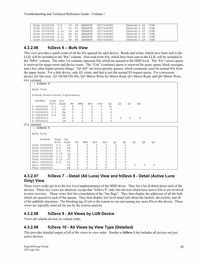
Troubleshooting and Technical Reference Guide - Volume 1
Disk 00100006 2,8 c5 c5 SEAGATE ST373405FC Cheetah-5 LP 73GB Disk 00100007 2,9 53 53 SEAGATE ST373405FC Cheetah-5 LP 73GB Disk 00100008 2,10 36 36 SEAGATE ST373405FC Cheetah-5 LP 73GB Disk 00100009 2,11 6e 6e SEAGATE ST373405FC Cheetah-5 LP 73GB Disk 0010000a 2,12 65 65 SEAGATE ST373405FC Cheetah-5 LP 73GB Disk 0010000b 2,13 49 49 SEAGATE ST373405FC Cheetah-5 LP 73GB
4.3.2.06 fcDevs 6 – Bufs View This view provides a quick count of all the IOs queued for each device. Reads and writes, which have been sent to the LLD, will be included in the “Rw” column. Non read-write IOs, which have been sent to the LLD, will be included in the “NRw” column. The other 3-6 columns represent IOs which are queued at the HDD level. The “Err” (error) queue is reserved for target resets and device resets. The “Con” (continue) queue is reserved for async opens, block reassigns, and a few other higher priority things. “Q1-Q4” are lower priority queues, which commonly used for normal IOs from the upper layers. For a disk device, only Q1 exists, and that is just the normal IO request queue. For a processor device, Q1-Q4 exist: Q1=SCSICON IOs, Q2=Mirror Write for Mirror Read, Q3=Mirror Read, and Q4=Mirror Write. (4.x version)
-> fcDevs 6 Bufs View D=disk,E=enclosure,P=processor DevNum Tray Cur Slot Alpa Rw NRw Err Con Q1 Q2 Q3 Q4 D 00000001 3,1 c3 8 0 0 0 32 D 00000002 3,2 bc 8 0 0 0 0 D 00000003 3,3 ba 5 0 0 0 0 D 00000004 3,4 b9 1 0 0 0 0 P 00f00011 02 0 0 0 0 0 0 0 0 E 00000010 1e 0 0 0 0 0
(5.x version) -> fcDevs 6 Bufs View DevNum Tray Cur Slot Alpa Rw NRw Err Con Q1 Q2 Q3 Q4 Q5 Disk 00000001 0,1 ef 0 0 0 0 0 0 Disk 00000002 0,2 e8 0 0 0 0 0 0 Disk 00000003 0,3 e4 0 0 0 0 0 0 Disk 0000000a 0,10 3a 0 0 0 0 0 0 Disk 0000000b 0,11 72 0 0 0 0 0 0 Disk 0000000c 0,12 67 0 0 0 0 0 0 Encl 00000010 0,0 25 0 0 0 0 0 0 Lmir 00f00011 02 0 0 0 0 0 0 0 0 0 This 00e00011 e8 0 0 0 0 0 0
4.3.2.07 fcDevs 7 - Detail (All Luns) View and fcDevs 8 - Detail (Active Luns Only) View These views really get in to the low level implementation of the HDD driver. They list a lot of detail about each of the devices. These two views are identical, except that “fcDevs 8” only lists devices which have active IOs or are involved in error recovery. These views first list a translation of the “lun flags”. They then display the addresses of all the bufs which are queued to each of the queues. They then display low level detail info about the lunInfo, deviceInfo, and all of the pathInfo structures. The blocking tag (if set) is the reason we are not issuing any more IOs to this device. These views are typically reserved for use by the system analysts.
4.3.2.08 fcDevs 9 - All Views by LUN Device Views all volume devices in volume order.
4.3.2.09 fcDevs 10 - All Views by View Type (Detailed) This provides detailed output of all of the views in view order. Similar to fcDevs 1 but includes all devices not just active devices.
EngenioStorage Group LSI Logic, Inc.
83
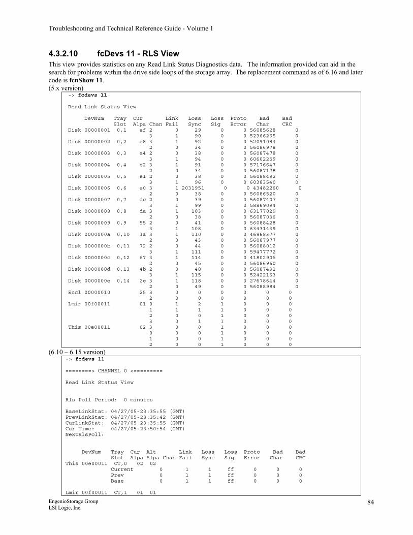
Troubleshooting and Technical Reference Guide - Volume 1
4.3.2.10 fcDevs 11 - RLS View This view provides statistics on any Read Link Status Diagnostics data. The information provided can aid in the search for problems within the drive side loops of the storage array. The replacement command as of 6.16 and later code is fcnShow 11. (5.x version)
-> fcdevs 11 Read Link Status View DevNum Tray Cur Link Loss Loss Proto Bad Bad Slot Alpa Chan Fail Sync Sig Error Char CRC Disk 00000001 0,1 ef 2 0 29 0 0 56085628 0 3 1 90 0 0 52366265 0 Disk 00000002 0,2 e8 3 1 92 0 0 52091084 0 2 0 34 0 0 56086978 0 Disk 00000003 0,3 e4 2 0 38 0 0 56087478 0 3 1 94 0 0 60602259 0 Disk 00000004 0,4 e2 3 1 91 0 0 57176647 0 2 0 34 0 0 56087178 0 Disk 00000005 0,5 e1 2 0 38 0 0 56088492 0 3 1 96 0 0 60383540 0 Disk 00000006 0,6 e0 3 1 2031951 0 0 43482260 0 2 0 38 0 0 56086520 0 Disk 00000007 0,7 dc 2 0 39 0 0 56087407 0 3 1 99 0 0 58869094 0 Disk 00000008 0,8 da 3 1 103 0 0 63177029 0 2 0 38 0 0 56087036 0 Disk 00000009 0,9 55 2 0 41 0 0 56088428 0 3 1 108 0 0 63431439 0 Disk 0000000a 0,10 3a 3 1 110 0 0 46968377 0 2 0 43 0 0 56087977 0 Disk 0000000b 0,11 72 2 0 44 0 0 56088012 0 3 1 111 0 0 59477772 0 Disk 0000000c 0,12 67 3 1 114 0 0 41802906 0 2 0 45 0 0 56086960 0 Disk 0000000d 0,13 4b 2 0 48 0 0 56087492 0 3 1 115 0 0 52422163 0 Disk 0000000e 0,14 2e 3 1 118 0 0 27678644 0 2 0 49 0 0 56088984 0 Encl 00000010 25 3 0 0 0 0 0 0 2 0 0 0 0 0 0 Lmir 00f00011 01 0 1 2 1 0 0 0 1 1 1 1 0 0 0 2 0 0 1 0 0 0 3 0 1 1 0 0 0 This 00e00011 02 3 0 0 1 0 0 0 0 0 0 1 0 0 0 1 0 0 1 0 0 0 2 0 0 1 0 0 0
(6.10 – 6.15 version) -> fcdevs 11 ========> CHANNEL 0 <========= Read Link Status View Rls Poll Period: 0 minutes BaseLinkStat: 04/27/05-23:35:55 (GMT) PrevLinkStat: 04/27/05-23:35:42 (GMT) CurLinkStat: 04/27/05-23:35:55 (GMT) Cur Time: 04/27/05-23:50:54 (GMT) NextRlsPoll: DevNum Tray Cur Alt Link Loss Loss Proto Bad Bad Slot Alpa Alpa Chan Fail Sync Sig Error Char CRC This 00e00011 CT,0 02 02 Current 0 1 1 ff 0 0 0 Prev 0 1 1 ff 0 0 0 Base 0 1 1 ff 0 0 0 Lmir 00f00011 CT,1 01 01
EngenioStorage Group LSI Logic, Inc.
84
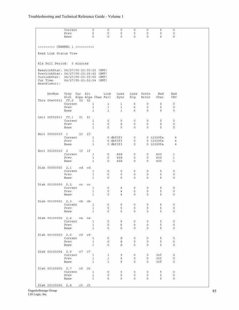
Troubleshooting and Technical Reference Guide - Volume 1
Current 0 0 0 0 0 0 0 Prev 0 0 0 0 0 0 0 Base 0 0 0 0 0 0 0 ========> CHANNEL 1 <========= Read Link Status View Rls Poll Period: 0 minutes BaseLinkStat: 04/27/05-23:35:55 (GMT) PrevLinkStat: 04/27/05-23:35:42 (GMT) CurLinkStat: 04/27/05-23:35:55 (GMT) Cur Time: 04/27/05-23:50:54 (GMT) NextRlsPoll: DevNum Tray Cur Alt Link Loss Loss Proto Bad Bad Slot Alpa Alpa Chan Fail Sync Sig Error Char CRC This 00e00011 CT,0 02 02 Current 1 1 1 6 0 0 0 Prev 1 1 1 6 0 0 0 Base 1 1 1 6 0 0 0 Lmir 00f00011 CT,1 01 01 Current 1 0 0 0 0 0 0 Prev 1 0 0 0 0 0 0 Base 1 0 0 0 0 0 0 Encl 00000010 1 23 23 Current 1 0 dbf3f3 0 0 12329fa 4 Prev 1 0 dbf3f3 0 0 12329fa 4 Base 1 0 dbf3f3 0 0 12329fa 4 Encl 00100010 2 1f 1f Current 1 0 46d 0 0 400 1 Prev 1 0 46d 0 0 400 1 Base 1 0 46d 0 0 400 1 Disk 0000000f 2,1 cd cd Current 1 0 0 0 0 5 0 Prev 1 0 0 0 0 5 0 Base 1 0 0 0 0 5 0 Disk 00100000 2,2 cc cc Current 1 0 4 0 0 5 0 Prev 1 0 4 0 0 5 0 Base 1 0 4 0 0 5 0 Disk 00100001 2,3 cb cb Current 1 0 5 0 0 5 0 Prev 1 0 5 0 0 5 0 Base 1 0 5 0 0 5 0 Disk 00100002 2,4 ca ca Current 1 0 6 0 0 5 0 Prev 1 0 6 0 0 5 0 Base 1 0 6 0 0 5 0 Disk 00100003 2,5 c9 c9 Current 1 0 d 0 0 5 0 Prev 1 0 d 0 0 5 0 Base 1 0 d 0 0 5 0 Disk 00100004 2,6 c7 c7 Current 1 1 9 0 0 35f 0 Prev 1 1 9 0 0 35f 0 Base 1 1 9 0 0 35f 0 Disk 00100005 2,7 c6 c6 Current 1 0 0 0 0 5 0 Prev 1 0 0 0 0 5 0 Base 1 0 0 0 0 5 0 Disk 00100006 2,8 c5 c5
EngenioStorage Group LSI Logic, Inc.
85
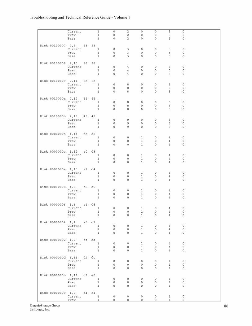
Troubleshooting and Technical Reference Guide - Volume 1
Current 1 0 2 0 0 5 0 Prev 1 0 2 0 0 5 0 Base 1 0 2 0 0 5 0 Disk 00100007 2,9 53 53 Current 1 0 3 0 0 5 0 Prev 1 0 3 0 0 5 0 Base 1 0 3 0 0 5 0 Disk 00100008 2,10 36 36 Current 1 0 4 0 0 5 0 Prev 1 0 4 0 0 5 0 Base 1 0 4 0 0 5 0 Disk 00100009 2,11 6e 6e Current 1 0 8 0 0 5 0 Prev 1 0 8 0 0 5 0 Base 1 0 8 0 0 5 0 Disk 0010000a 2,12 65 65 Current 1 0 8 0 0 5 0 Prev 1 0 8 0 0 5 0 Base 1 0 8 0 0 5 0 Disk 0010000b 2,13 49 49 Current 1 0 9 0 0 5 0 Prev 1 0 9 0 0 5 0 Base 1 0 9 0 0 5 0 Disk 0000000e 1,14 dc d2 Current 1 0 0 1 0 4 0 Prev 1 0 0 1 0 4 0 Base 1 0 0 1 0 4 0 Disk 0000000c 1,12 e0 d3 Current 1 0 0 1 0 4 0 Prev 1 0 0 1 0 4 0 Base 1 0 0 1 0 4 0 Disk 0000000a 1,10 e1 d4 Current 1 0 0 1 0 4 0 Prev 1 0 0 1 0 4 0 Base 1 0 0 1 0 4 0 Disk 00000008 1,8 e2 d5 Current 1 0 0 1 0 4 0 Prev 1 0 0 1 0 4 0 Base 1 0 0 1 0 4 0 Disk 00000006 1,6 e4 d6 Current 1 0 0 1 0 4 0 Prev 1 0 0 1 0 4 0 Base 1 0 0 1 0 4 0 Disk 00000004 1,4 e8 d9 Current 1 0 0 1 0 4 0 Prev 1 0 0 1 0 4 0 Base 1 0 0 1 0 4 0 Disk 00000002 1,2 ef da Current 1 0 0 1 0 4 0 Prev 1 0 0 1 0 4 0 Base 1 0 0 1 0 4 0 Disk 0000000d 1,13 d2 dc Current 1 0 0 0 0 1 0 Prev 1 0 0 0 0 1 0 Base 1 0 0 0 0 1 0 Disk 0000000b 1,11 d3 e0 Current 1 0 0 0 0 1 0 Prev 1 0 0 0 0 1 0 Base 1 0 0 0 0 1 0 Disk 00000009 1,9 d4 e1 Current 1 0 0 0 0 1 0 Prev 1 0 0 0 0 1 0
EngenioStorage Group LSI Logic, Inc.
86
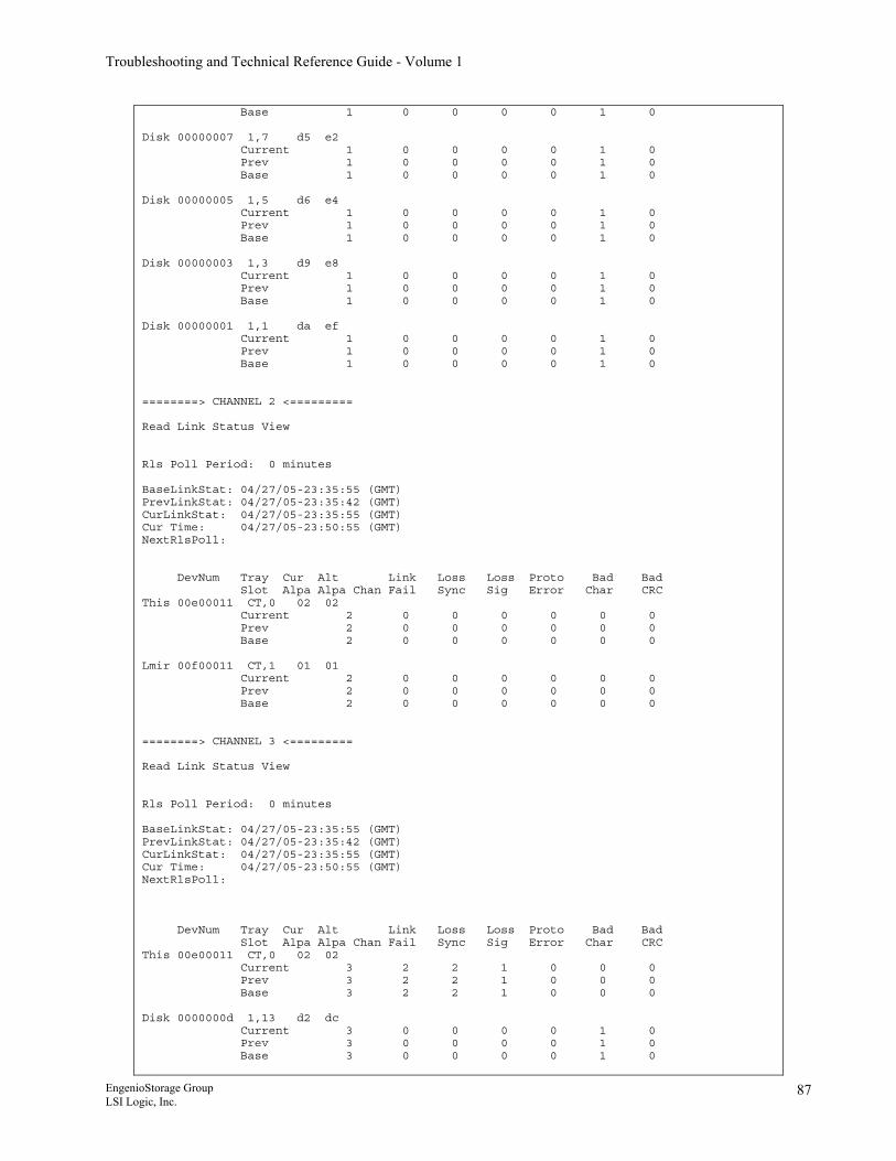
Troubleshooting and Technical Reference Guide - Volume 1
Base 1 0 0 0 0 1 0 Disk 00000007 1,7 d5 e2 Current 1 0 0 0 0 1 0 Prev 1 0 0 0 0 1 0 Base 1 0 0 0 0 1 0 Disk 00000005 1,5 d6 e4 Current 1 0 0 0 0 1 0 Prev 1 0 0 0 0 1 0 Base 1 0 0 0 0 1 0 Disk 00000003 1,3 d9 e8 Current 1 0 0 0 0 1 0 Prev 1 0 0 0 0 1 0 Base 1 0 0 0 0 1 0 Disk 00000001 1,1 da ef Current 1 0 0 0 0 1 0 Prev 1 0 0 0 0 1 0 Base 1 0 0 0 0 1 0 ========> CHANNEL 2 <========= Read Link Status View Rls Poll Period: 0 minutes BaseLinkStat: 04/27/05-23:35:55 (GMT) PrevLinkStat: 04/27/05-23:35:42 (GMT) CurLinkStat: 04/27/05-23:35:55 (GMT) Cur Time: 04/27/05-23:50:55 (GMT) NextRlsPoll: DevNum Tray Cur Alt Link Loss Loss Proto Bad Bad Slot Alpa Alpa Chan Fail Sync Sig Error Char CRC This 00e00011 CT,0 02 02 Current 2 0 0 0 0 0 0 Prev 2 0 0 0 0 0 0 Base 2 0 0 0 0 0 0 Lmir 00f00011 CT,1 01 01 Current 2 0 0 0 0 0 0 Prev 2 0 0 0 0 0 0 Base 2 0 0 0 0 0 0 ========> CHANNEL 3 <========= Read Link Status View Rls Poll Period: 0 minutes BaseLinkStat: 04/27/05-23:35:55 (GMT) PrevLinkStat: 04/27/05-23:35:42 (GMT) CurLinkStat: 04/27/05-23:35:55 (GMT) Cur Time: 04/27/05-23:50:55 (GMT) NextRlsPoll: DevNum Tray Cur Alt Link Loss Loss Proto Bad Bad Slot Alpa Alpa Chan Fail Sync Sig Error Char CRC This 00e00011 CT,0 02 02 Current 3 2 2 1 0 0 0 Prev 3 2 2 1 0 0 0 Base 3 2 2 1 0 0 0 Disk 0000000d 1,13 d2 dc Current 3 0 0 0 0 1 0 Prev 3 0 0 0 0 1 0 Base 3 0 0 0 0 1 0
EngenioStorage Group LSI Logic, Inc.
87
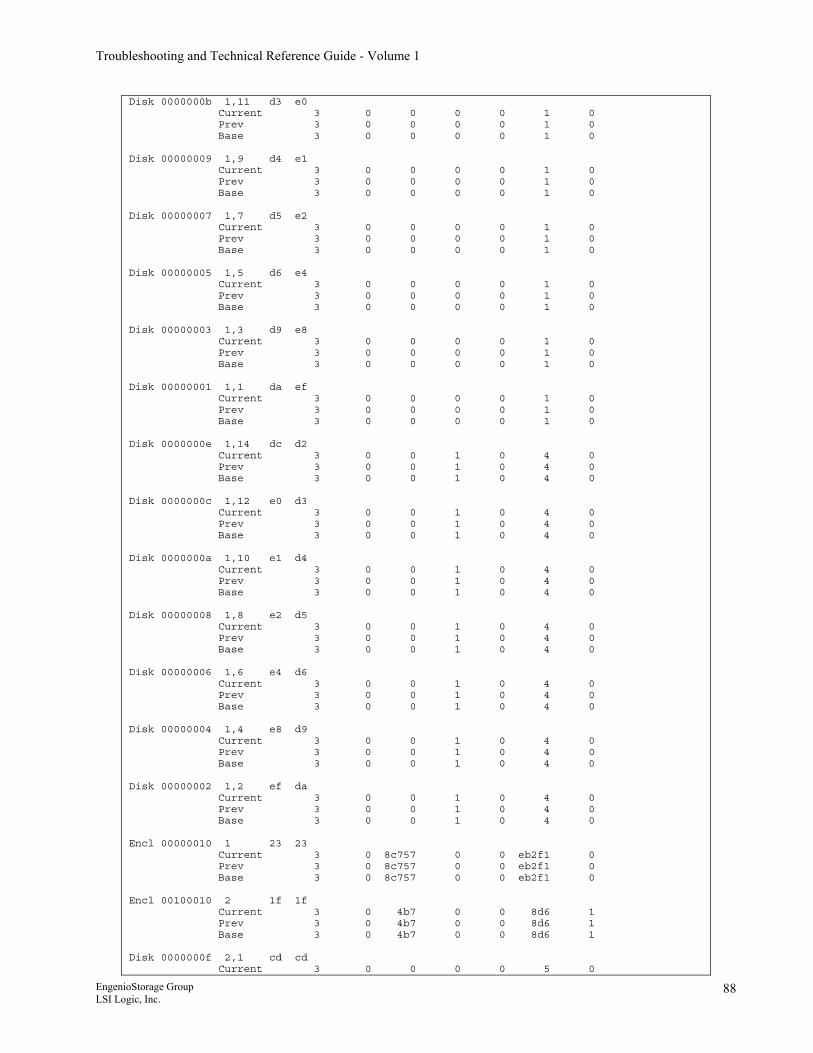
Troubleshooting and Technical Reference Guide - Volume 1
Disk 0000000b 1,11 d3 e0 Current 3 0 0 0 0 1 0 Prev 3 0 0 0 0 1 0 Base 3 0 0 0 0 1 0 Disk 00000009 1,9 d4 e1 Current 3 0 0 0 0 1 0 Prev 3 0 0 0 0 1 0 Base 3 0 0 0 0 1 0 Disk 00000007 1,7 d5 e2 Current 3 0 0 0 0 1 0 Prev 3 0 0 0 0 1 0 Base 3 0 0 0 0 1 0 Disk 00000005 1,5 d6 e4 Current 3 0 0 0 0 1 0 Prev 3 0 0 0 0 1 0 Base 3 0 0 0 0 1 0 Disk 00000003 1,3 d9 e8 Current 3 0 0 0 0 1 0 Prev 3 0 0 0 0 1 0 Base 3 0 0 0 0 1 0 Disk 00000001 1,1 da ef Current 3 0 0 0 0 1 0 Prev 3 0 0 0 0 1 0 Base 3 0 0 0 0 1 0 Disk 0000000e 1,14 dc d2 Current 3 0 0 1 0 4 0 Prev 3 0 0 1 0 4 0 Base 3 0 0 1 0 4 0 Disk 0000000c 1,12 e0 d3 Current 3 0 0 1 0 4 0 Prev 3 0 0 1 0 4 0 Base 3 0 0 1 0 4 0 Disk 0000000a 1,10 e1 d4 Current 3 0 0 1 0 4 0 Prev 3 0 0 1 0 4 0 Base 3 0 0 1 0 4 0 Disk 00000008 1,8 e2 d5 Current 3 0 0 1 0 4 0 Prev 3 0 0 1 0 4 0 Base 3 0 0 1 0 4 0 Disk 00000006 1,6 e4 d6 Current 3 0 0 1 0 4 0 Prev 3 0 0 1 0 4 0 Base 3 0 0 1 0 4 0 Disk 00000004 1,4 e8 d9 Current 3 0 0 1 0 4 0 Prev 3 0 0 1 0 4 0 Base 3 0 0 1 0 4 0 Disk 00000002 1,2 ef da Current 3 0 0 1 0 4 0 Prev 3 0 0 1 0 4 0 Base 3 0 0 1 0 4 0 Encl 00000010 1 23 23 Current 3 0 8c757 0 0 eb2f1 0 Prev 3 0 8c757 0 0 eb2f1 0 Base 3 0 8c757 0 0 eb2f1 0 Encl 00100010 2 1f 1f Current 3 0 4b7 0 0 8d6 1 Prev 3 0 4b7 0 0 8d6 1 Base 3 0 4b7 0 0 8d6 1 Disk 0000000f 2,1 cd cd Current 3 0 0 0 0 5 0
EngenioStorage Group LSI Logic, Inc.
88
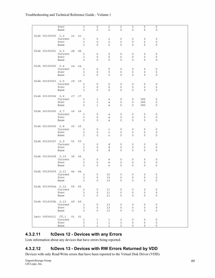
Troubleshooting and Technical Reference Guide - Volume 1
Prev 3 0 0 0 0 5 0 Base 3 0 0 0 0 5 0 Disk 00100000 2,2 cc cc Current 3 0 2 0 0 0 0 Prev 3 0 2 0 0 0 0 Base 3 0 2 0 0 0 0 Disk 00100001 2,3 cb cb Current 3 0 5 0 0 0 0 Prev 3 0 5 0 0 0 0 Base 3 0 5 0 0 0 0 Disk 00100002 2,4 ca ca Current 3 0 5 0 0 0 0 Prev 3 0 5 0 0 0 0 Base 3 0 5 0 0 0 0 Disk 00100003 2,5 c9 c9 Current 3 0 6 0 0 0 0 Prev 3 0 6 0 0 0 0 Base 3 0 6 0 0 0 0 Disk 00100004 2,6 c7 c7 Current 3 1 a 0 0 385 0 Prev 3 1 a 0 0 385 0 Base 3 1 a 0 0 385 0 Disk 00100005 2,7 c6 c6 Current 3 0 a 0 0 0 0 Prev 3 0 a 0 0 0 0 Base 3 0 a 0 0 0 0 Disk 00100006 2,8 c5 c5 Current 3 0 c 0 0 0 0 Prev 3 0 c 0 0 0 0 Base 3 0 c 0 0 0 0 Disk 00100007 2,9 53 53 Current 3 0 d 0 0 0 0 Prev 3 0 d 0 0 0 0 Base 3 0 d 0 0 0 0 Disk 00100008 2,10 36 36 Current 3 0 e 0 0 0 0 Prev 3 0 e 0 0 0 0 Base 3 0 e 0 0 0 0 Disk 00100009 2,11 6e 6e Current 3 0 10 0 0 0 0 Prev 3 0 10 0 0 0 0 Base 3 0 10 0 0 0 0 Disk 0010000a 2,12 65 65 Current 3 0 11 0 0 0 0 Prev 3 0 11 0 0 0 0 Base 3 0 11 0 0 0 0 Disk 0010000b 2,13 49 49 Current 3 0 13 0 0 0 0 Prev 3 0 13 0 0 0 0 Base 3 0 13 0 0 0 0 Lmir 00f00011 CT,1 01 01 Current 3 1 1 3 0 0 0 Prev 3 1 1 3 0 0 0 Base 3 1 1 3 0 0 0
4.3.2.11 fcDevs 12 - Devices with any Errors Lists information about any devices that have errors being reported.
4.3.2.12 fcDevs 13 - Devices with RW Errors Returned by VDD Devices with only Read/Write errors that have been reported to the Virtual Disk Driver (VDD).
EngenioStorage Group LSI Logic, Inc.
89
Troubleshooting and Technical Reference Guide - Volume 1
4.3.2.13 fcDevs 14 - Devices with Major Errors View of any device that is reporting any major errors.
4.3.2.14 hddDump 06.15 and lower Dumps detailed hdd errors on a per drive basis. Includes output from the following fcDevs commands:
• fcDevs 2 • fcDevs 3 • fcDevs 4 • fcDevs 5 • fcDevs 6 • fcDevs 7 • fcDevs 11 • fcDevs 12 • fcDevs 13 • fcDevs 14
06.16 andhigher There is no equivalant single command to perform this funtion.
EngenioStorage Group LSI Logic, Inc.
90
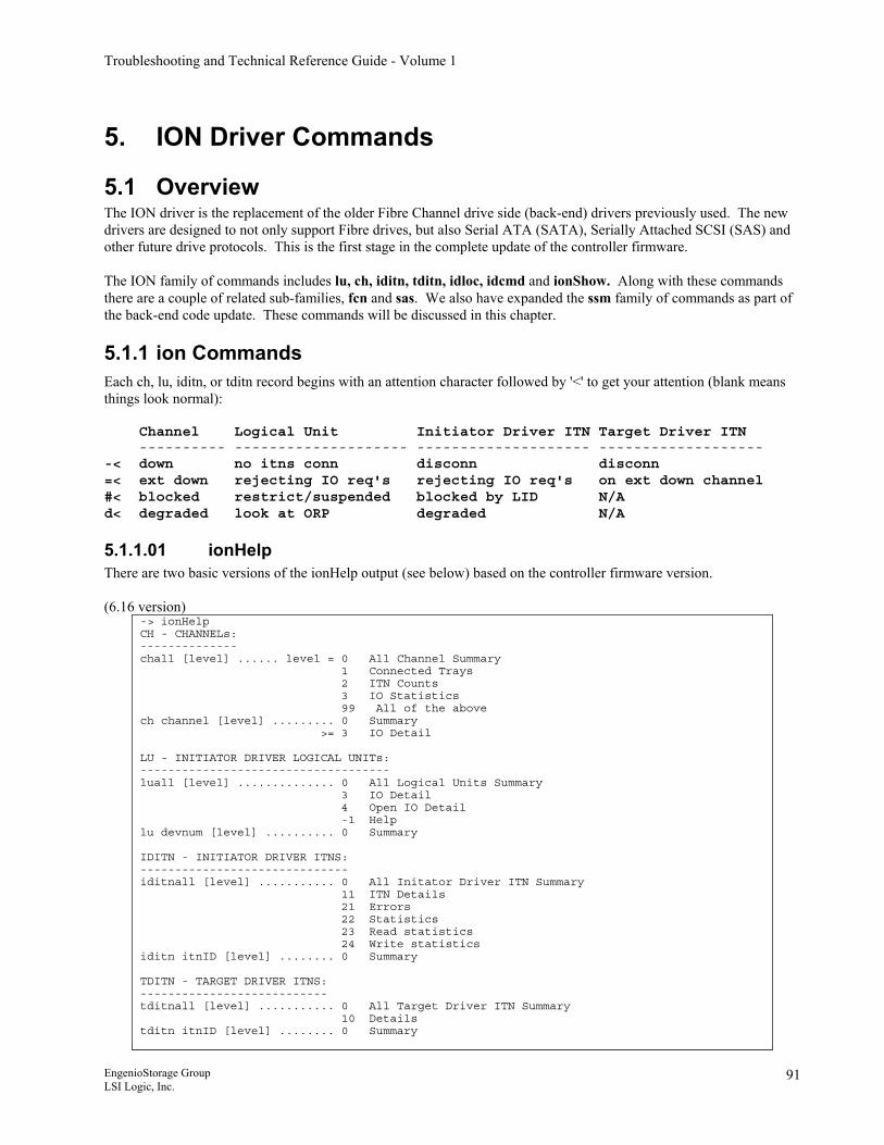
Troubleshooting and Technical Reference Guide - Volume 1
5. ION Driver Commands
5.1 Overview The ION driver is the replacement of the older Fibre Channel drive side (back-end) drivers previously used. The new drivers are designed to not only support Fibre drives, but also Serial ATA (SATA), Serially Attached SCSI (SAS) and other future drive protocols. This is the first stage in the complete update of the controller firmware. The ION family of commands includes lu, ch, iditn, tditn, idloc, idcmd and ionShow. Along with these commands there are a couple of related sub-families, fcn and sas. We also have expanded the ssm family of commands as part of the back-end code update. These commands will be discussed in this chapter.
5.1.1 ion Commands Each ch, lu, iditn, or tditn record begins with an attention character followed by '<' to get your attention (blank means things look normal): Channel Logical Unit Initiator Driver ITN Target Driver ITN ---------- -------------------- -------------------- ------------------- -< down no itns conn disconn disconn =< ext down rejecting IO req's rejecting IO req's on ext down channel #< blocked restrict/suspended blocked by LID N/A d< degraded look at ORP degraded N/A
5.1.1.01 ionHelp There are two basic versions of the ionHelp output (see below) based on the controller firmware version. (6.16 version)
-> ionHelp CH - CHANNELs: -------------- chall [level] ...... level = 0 All Channel Summary 1 Connected Trays 2 ITN Counts 3 IO Statistics 99 All of the above ch channel [level] ......... 0 Summary >= 3 IO Detail LU - INITIATOR DRIVER LOGICAL UNITs: ------------------------------------ luall [level] .............. 0 All Logical Units Summary 3 IO Detail 4 Open IO Detail -1 Help lu devnum [level] .......... 0 Summary IDITN - INITIATOR DRIVER ITNS: ------------------------------ iditnall [level] ........... 0 All Initator Driver ITN Summary 11 ITN Details 21 Errors 22 Statistics 23 Read statistics 24 Write statistics iditn itnID [level] ........ 0 Summary TDITN - TARGET DRIVER ITNS: --------------------------- tditnall [level] ........... 0 All Target Driver ITN Summary 10 Details tditn itnID [level] ........ 0 Summary
EngenioStorage Group LSI Logic, Inc.
91
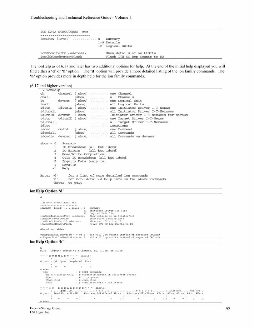
Troubleshooting and Technical Reference Guide - Volume 1
ION DATA STRUCTURES, etc: ------------------------- ionShow [level] ............ 0 Summary 1-9 Details 12 Logical Units ionShowLtdItn <address> Show details of an LtdItn ionChkCondMemoryFlush Flush ITN CC Rep Counts to DQ
The ionHelp as of 6.17 and later has two additional options for help. At the end of the initial help displayed you will find either a ‘d’ or ‘h’ option. The ‘d’ option will provide a more detailed listing of the ion family commands. The ‘h’ option provides more in depth help for the ion family commands. (6.17 and higher version)
-> ionHelp ch channel [,show] ......... one Channel chall [show] ......... all Channels lu devnum [,show] ......... one Logical Unit luall [show] ......... all Logical Units iditn iditnID [,show] ......... one Initiator Driver I-T-Nexus iditnall [show] ......... all Initiator Driver I-T-Nexuses iditnlu devnum [,show] ......... Initiator Driver I-T-Nexuses for devnum tditn tditnID [,show] ......... one Target Driver I-T-Nexus tditnall ......... all Target Driver I-T-Nexuses idloc ......... Locations idcmd cmdId [,show] ......... one Command idcmdall [show] ......... all Commands idcmdlu devnum [,show] ......... all Commands on devnum show = 0 Summary 1 IO Breakdown (all but idcmd) 2 IO Errors (all but idcmd) 3 Read/Write Completion 4 Ctlr IO Breakdown (all but idcmd) 5 Inquiry Data (only lu) 9 Details -1 Help Enter 'd' for a list of more detailed ion commands 'h' for more detailed help info on the above commands 'Enter' to quit
ionHelp Option ‘d’ d ION DATA STRUCTURES, etc: ------------------------- ionShow [level] .....level = 0 Summary 11 Initiator Driver ITN list 12 Logical Unit list ionShowInitiatorPort <address> Show details of an IniatorPort ionShowDriveSummary Show drive inquiry data ionShowDriveCertId <devnum> Show certification id ionChkCondMemoryFlush Flush ITN CC Rep Counts to DQ Global Variables: ----------------- ccRepeatEnabledForSid = 0 or 1 sid will log counts instead of repeated CkConds ccRepeatEnabledForStd = 0 or 1 std will log counts instead of repeated CkConds
ionHelp Option ‘h’ h NOTE: 'Object' refers to a Channel, LU, IDITN, or TDITN * * * S U M M A R Y * * * (show=0) :............IOs........... Object : Qd Open Completed Errs ------ :--- ----- ---------- ----- : 0 0 0 0 where: IOs : # SCSI commands Qd (initiator-only) : # currently queued in Initiator Driver Open : # in progress Completed : # completed Errs : # completed with a bad status * * * I O B R E A K D O W N * * * (show=1) :.....Open IOs.....:..........R E A D S.........:........W R I T E S.........:..NON R/W...:..WRT/VFY.. Object : Read Write NonRW : #Success BlksXfered #Errs : #Success BlksXfered #Errs :#Succ #Errs :#Succ #Errs ------ :----- ----- ----- :---------- ---------- ----- :---------- ---------- ----- :----- ----- :----- ----- : 0 0 0 : 0 0 0 : 0 0 0 : 0 0 : 0 0 where:
EngenioStorage Group LSI Logic, Inc.
92
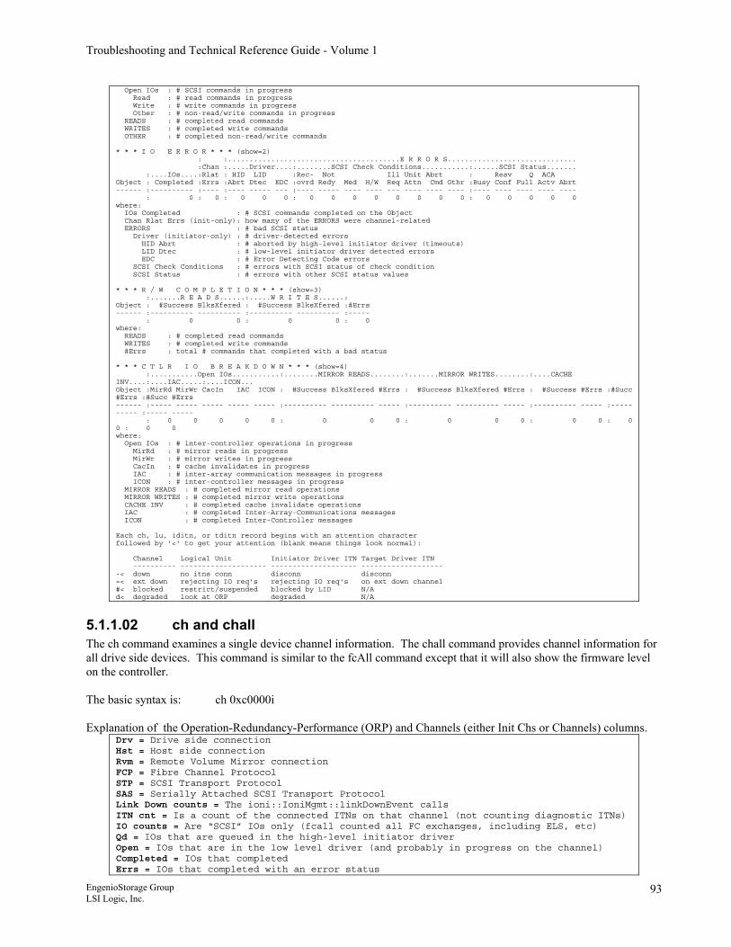
Troubleshooting and Technical Reference Guide - Volume 1
Open IOs : # SCSI commands in progress Read : # read commands in progress Write : # write commands in progress Other : # non-read/write commands in progress READS : # completed read commands WRITES : # completed write commands OTHER : # completed non-read/write commands * * * I O E R R O R * * * (show=2) : :........................................E R R O R S.............................. :Chan :.....Driver....:........SCSI Check Conditions...........:......SCSI Status....... :....IOs....:Rlat : HID LID :Rec- Not Ill Unit Abrt : Resv Q ACA Object : Completed :Errs :Abrt Dtec EDC :ovrd Redy Med H/W Req Attn Cmd Othr :Busy Conf Full Actv Abrt ------ :---------- :---- :---- ----- --- :---- ----- ---- ---- --- ---- ---- ---- :---- ---- ---- ---- ---- : 0 : 0 : 0 0 0 : 0 0 0 0 0 0 0 0 : 0 0 0 0 0 where: IOs Completed : # SCSI commands completed on the Object Chan Rlat Errs (init-only): how many of the ERRORS were channel-related ERRORS : # bad SCSI status Driver (initiator-only) : # driver-detected errors HID Abrt : # aborted by high-level initiator driver (timeouts) LID Dtec : # low-level initiator driver detected errors EDC : # Error Detecting Code errors SCSI Check Conditions : # errors with SCSI status of check condition SCSI Status : # errors with other SCSI status values * * * R / W C O M P L E T I O N * * * (show=3) :.......R E A D S......:.....W R I T E S......: Object : #Success BlksXfered : #Success BlksXfered :#Errs ------ :---------- ---------- :---------- ---------- :----- : 0 0 : 0 0 : 0 where: READS : # completed read commands WRITES : # completed write commands #Errs : total # commands that completed with a bad status * * * C T L R I O B R E A K D O W N * * * (show=4) :...........Open IOs...........:........MIRROR READS........:.......MIRROR WRITES........:....CACHE INV....:....IAC.....:....ICON... Object :MirRd MirWr CacIn IAC ICON : #Success BlksXfered #Errs : #Success BlksXfered #Errs : #Success #Errs :#Succ #Errs :#Succ #Errs ------ :----- ----- ----- ----- ----- :---------- ---------- ----- :---------- ---------- ----- :---------- ----- :----- ----- :----- ----- : 0 0 0 0 0 : 0 0 0 : 0 0 0 : 0 0 : 0 0 : 0 0 where: Open IOs : # inter-controller operations in progress MirRd : # mirror reads in progress MirWr : # mirror writes in progress CacIn : # cache invalidates in progress IAC : # inter-array communication messages in progress ICON : # inter-controller messages in progress MIRROR READS : # completed mirror read operations MIRROR WRITES : # completed mirror write operations CACHE INV : # completed cache invalidate operations IAC : # completed Inter-Array-Communications messages ICON : # completed Inter-Controller messages Each ch, lu, iditn, or tditn record begins with an attention character followed by '<' to get your attention (blank means things look normal): Channel Logical Unit Initiator Driver ITN Target Driver ITN ---------- -------------------- -------------------- ------------------- -< down no itns conn disconn disconn =< ext down rejecting IO req's rejecting IO req's on ext down channel #< blocked restrict/suspended blocked by LID N/A d< degraded look at ORP degraded N/A
5.1.1.02 ch and chall The ch command examines a single device channel information. The chall command provides channel information for all drive side devices. This command is similar to the fcAll command except that it will also show the firmware level on the controller. The basic syntax is: ch 0xc0000i Explanation of the Operation-Redundancy-Performance (ORP) and Channels (either Init Chs or Channels) columns.
Drv = Drive side connection Hst = Host side connection Rvm = Remote Volume Mirror connection FCP = Fibre Channel Protocol STP = SCSI Transport Protocol SAS = Serially Attached SCSI Transport Protocol Link Down counts = The ioni::IoniMgmt::linkDownEvent calls ITN cnt = Is a count of the connected ITNs on that channel (not counting diagnostic ITNs) IO counts = Are “SCSI” IOs only (fcall counted all FC exchanges, including ELS, etc) Qd = IOs that are queued in the high-level initiator driver Open = IOs that are in the low level driver (and probably in progress on the channel) Completed = IOs that completed Errs = IOs that completed with an error status
EngenioStorage Group LSI Logic, Inc.
93
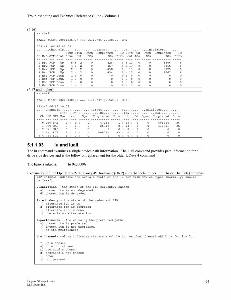
Troubleshooting and Technical Reference Guide - Volume 1
(6.16) -> chall chAll (Tick 0000183578) ==> 06/19/06-20:38:08 (GMT) 6091-A 06.16.82.00 .......Channels......:...........Target..........:...........Initiator.......... Link :ITN Open Completed IO :ITN Qd Open Completed IO Ch H/D STP Stat Down :cnt IOs IOs Errs :cnt IOs IOs IOs Errs -- --- --- ---- ---- :--- ----- ---------- ----- :--- --- ----- ---------- ----- 0 Drv FCP Up 5 : 2 0 426 0 : 13 0 0 3306 6 1 Drv FCP Up 4 : 2 0 457 0 : 13 0 0 3365 6 2 Drv FCP Up 2 : 2 0 458 0 : 13 0 0 3975 6 3 Drv FCP Up 2 : 2 0 434 0 : 13 0 0 3762 6 4 Hst FCP Down 1 : 0 0 0 0 : 0 0 0 0 0 5 Hst FCP Down 1 : 0 0 0 0 : 0 0 0 0 0 6 Hst FCP Down 1 : 0 0 0 0 : 0 0 0 0 0 7 Hst FCP Down 1 : 2 0 0 0 : 1 0 0 0 0
(6.17 and higher) -> chall chAll (Tick 0022048817) ==> 01/09/07-00:52:39 (GMT) 1932-A 06.17.30.05 .....Channels.....:...........Target...........:............Initiator.......... Link :ITN :..........IOs..........:ITN :............IOs........... Ch H/D STP Down :cnt : Open Completed Errs :cnt : Qd Open Completed Errs ---- --- --- ---- :--- :----- ---------- ----- :--- :--- ----- ---------- ----- 0 Drv SAS 0 : 1 : 0 47034 1 : 13 : 0 0 605944 36 1 Drv SAS 0 : 1 : 0 26543 0 : 13 : 0 0 410511 36 -< 2 Hst SAS 0 : 0 : 0 0 0 : 0 : 0 0 0 0 3 Hst FCP 1 : 1 : 1 408011 39 : 0 : 0 0 0 0 -< 4 Hst FCP 1 : 0 : 0 0 0 : 0 : 0 0 0 0
5.1.1.03 lu and luall The lu command examines a single device path information. The luall command provides path information for all drive side devices and is the follow on replacement for the older fcDevs 4 command The basic syntax is: lu 0xc0000i Explanation of the Operation-Redundancy-Performance (ORP) and Channels (either Init Chs or Channels) columns.
ORP columns indicate the overall state of the lu for disk device types (normally, should be “+++”). O=operation - the state of the ITN currently chosen +) chosen itn is not degraded d) chosen itn is degraded R=redundancy - the state of the redundant ITN +) alternate itn is up d) alternate itn is degraded -) alternate itn is down x) there is no alternate itn P=performance - Are we using the preferred path? +) chosen itn is preferred -) chosen itn is not preferred ) no itn preferences The Channels column indicates the state of the itn on that channel which is for its lu. *) up & chosen +) up & not chosen D) degraded & chosen d) degraded & not chosen -) down x) not present
EngenioStorage Group LSI Logic, Inc.
94
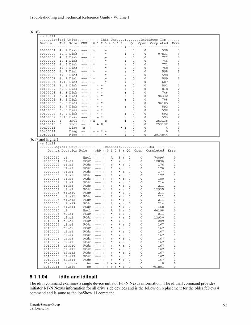
Troubleshooting and Technical Reference Guide - Volume 1
(6.16) -> luall ......Logical Units......:.... Init Chs....:.......Initiator IOs....... Devnum T,S Role ORP ::0 1 2 3 4 5 6 7 : Qd Open Completed Errs -------- ----- ----- --- : - - - - - - - - : --- ----- ---------- ----- 00000001 4, 1 Disk +++ : * + : 0 0 598 3 00000002 4, 2 Disk +++ : + * : 0 0 97833 9 00000003 4, 3 Disk +++ : * + : 0 0 722 3 00000004 4, 4 Disk +++ : + * : 0 0 746 3 00000005 4, 5 Disk +++ : * + : 0 0 771 3 00000006 4, 6 Disk +++ : + * : 0 0 758 3 00000007 4, 7 Disk +++ : * + : 0 0 598 3 00000008 4, 8 Disk +++ : + * : 0 0 598 3 00000009 4, 9 Disk +++ : * + : 0 0 599 3 0000000a 4,10 Disk +++ : + * : 0 0 607 3 00100001 3, 1 Disk +++ : * + : 0 0 592 2 00100002 3, 2 Disk +++ : + * : 0 0 818 2 00100003 3, 3 Disk +++ : * + : 0 0 748 2 00100004 3, 4 Disk +++ : + * : 0 0 96332 5 00100005 3, 5 Disk +++ : * + : 0 0 708 2 00100006 3, 6 Disk +++ : + * : 0 0 96105 5 00100007 3, 7 Disk +++ : * + : 0 0 592 2 00100008 3, 8 Disk +++ : + * : 0 0 592 2 00100009 3, 9 Disk +++ : * + : 0 0 592 2 0010000a 3,10 Disk +++ : + * : 0 0 593 2 00000010 4 Encl ++ : A B : 0 0 253135 7 00100010 3 Encl ++ : A B : 0 0 253132 6 00d00011 Diag +x : * : 0 0 4 0 00e00011 Diag ++ : + + * + : 0 0 0 0 00f00011 Mirr ++ : + + + * : 0 0 2914844 0
(6.17 and higher) -> luall .......Logical Unit........: :Channels.:............IOs........... Devnum Location Role :ORP : 0 1 2 3 : Qd Open Completed Errs ---------- -------- ------ :--- : - - - - :--- ----- ---------- ----- 00100010 t1 Encl :++ : A B : 0 0 74896 0 00000001 t1,s1 FCdr :+++ : * + : 0 0 12896 1 00000002 t1,s2 FCdr :+++ : + * : 0 0 176 1 00000003 t1,s3 FCdr :+++ : * + : 0 0 176 1 00000004 t1,s4 FCdr :+++ : + * : 0 0 177 1 00000005 t1,s5 FCdr :+++ : * + : 0 0 177 1 00000006 t1,s6 FCdr :+++ : + * : 0 0 180 1 00000007 t1,s7 FCdr :+++ : * + : 0 0 214 1 00000008 t1,s8 FCdr :+++ : + * : 0 0 211 1 00000009 t1,s9 FCdr :+++ : * + : 0 0 12935 1 0000000a t1,s10 FCdr :+++ : + * : 0 0 211 1 0000000b t1,s11 FCdr :+++ : * + : 0 0 211 1 0000000c t1,s12 FCdr :+++ : + * : 0 0 211 1 0000000d t1,s13 FCdr :+++ : * + : 0 0 214 1 0000000e t1,s14 FCdr :+++ : + * : 0 0 168 1 00000010 t2 Encl :++ : A B : 0 0 64198 0 0000000f t2,s1 FCdr :+++ : * + : 0 0 211 1 00100000 t2,s2 FCdr :+++ : + * : 0 0 12930 1 00100001 t2,s3 FCdr :+++ : * + : 0 0 209 1 00100002 t2,s4 FCdr :+++ : + * : 0 0 167 1 00100003 t2,s5 FCdr :+++ : * + : 0 0 167 1 00100004 t2,s6 FCdr :+++ : + * : 0 0 167 1 00100005 t2,s7 FCdr :+++ : * + : 0 0 167 1 00100006 t2,s8 FCdr :+++ : + * : 0 0 167 1 00100007 t2,s9 FCdr :+++ : * + : 0 0 167 1 00100008 t2,s10 FCdr :+++ : + * : 0 0 167 1 00100009 t2,s11 FCdr :+++ : * + : 0 0 167 1 0010000a t2,s12 FCdr :+++ : + * : 0 0 167 1 0010000b t2,s13 FCdr :+++ : * + : 0 0 167 1 0010000c t2,s14 FCdr :+++ : + * : 0 0 167 1 00e00011 c,this Am :++ : * + + + : 0 0 0 0 00f00011 c,alt Bm :++ : + + + * : 0 0 791801 0
5.1.1.04 iditn and iditnall The iditn command examines a single device initiator I-T-N Nexus information. The iditnall command provides initiator I-T-N Nexus information for all drive side devices and is the follow on replacement for the older fcDevs 4 command and is same as the ionShow 11 command. EngenioStorage Group LSI Logic, Inc.
95
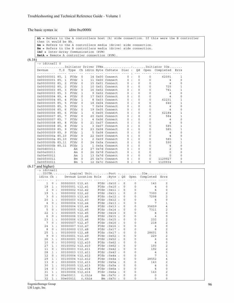
Troubleshooting and Technical Reference Guide - Volume 1
The basic syntax is: iditn 0xc0000i
Ah = Refers to the A controllers host (h) side connection. If this were the B controller then it would be Bh. Am = Refers to the A controllers media (drive) side connection. Bm = Refers to the B controllers media (drive) side connection. IAC = Inter-Array Communication (RVM) RmtA = Remote A controller connection (RVM).
(6.16) -> iditnall 0 ...............Initiator Driver ITNs...............:.......Initiator IOs....... Devnum T,S Type Ch iditn Byte CnState Disc : Qd Open Completed Errs ---------- ----- ----- -- ----- ---- -------- ---- : --- ----- ---------- ----- 0x00000001 85, 1 FCdr 0 14 0x00 Connect 0 : 0 0 62091 1 0x00000001 85, 1 FCdr 1 11 0x00 Connect 0 : 0 0 4 0 0x00000002 85, 2 FCdr 0 15 0x01 Connect 0 : 0 0 4 0 0x00000002 85, 2 FCdr 1 10 0x01 Connect 0 : 0 0 725 1 0x00000003 85, 3 FCdr 0 16 0x02 Connect 0 : 0 0 741 1 0x00000003 85, 3 FCdr 1 9 0x02 Connect 0 : 0 0 4 0 0x00000004 85, 4 FCdr 0 17 0x03 Connect 0 : 0 0 4 0 0x00000004 85, 4 FCdr 1 8 0x03 Connect 0 : 0 0 62231 1 0x00000005 85, 5 FCdr 0 18 0x04 Connect 0 : 0 0 646 1 0x00000005 85, 5 FCdr 1 7 0x04 Connect 0 : 0 0 4 0 0x00000006 85, 6 FCdr 0 19 0x05 Connect 0 : 0 0 4 0 0x00000006 85, 6 FCdr 1 6 0x05 Connect 0 : 0 0 62184 1 0x00000007 85, 7 FCdr 0 20 0x06 Connect 0 : 0 0 584 1 0x00000007 85, 7 FCdr 1 4 0x06 Connect 0 : 0 0 4 0 0x00000008 85, 8 FCdr 0 21 0x07 Connect 0 : 0 0 4 0 0x00000008 85, 8 FCdr 1 3 0x07 Connect 0 : 0 0 585 1 0x00000009 85, 9 FCdr 0 23 0x08 Connect 0 : 0 0 585 1 0x00000009 85, 9 FCdr 1 5 0x08 Connect 0 : 0 0 4 0 0x0000000a 85,10 FCdr 0 22 0x09 Connect 0 : 0 0 4 0 0x0000000a 85,10 FCdr 1 2 0x09 Connect 0 : 0 0 585 1 0x0000000b 85,11 FCdr 0 24 0x0a Connect 0 : 0 0 590 1 0x0000000b 85,11 FCdr 1 1 0x0a Connect 0 : 0 0 4 0 0x00d00011 Ah 2 27 0x7d Connect 0 : 0 0 2 0 0x00e00011 Am 0 26 0x7d Connect 0 : 0 0 0 0 0x00e00011 Am 1 13 0x7d Connect 0 : 0 0 0 0 0x00f00011 Bm 0 25 0x7c Connect 0 : 0 0 1129927 0 0x00f00011 Bm 1 12 0x7c Connect 0 : 0 0 1129934 0
(6.17 and higher) -> iditnall ...IDITN..:.......Logical Unit........:Port :............IOs........... iditn Ch : Devnum Location Role :Byte : Qd Open Completed Errs ------ -- :---------- -------- ------ :---- :--- ----- ---------- ----- 1 0 : 00000001 t12,s1 FCdr :0x10 : 0 0 143 2 18 1 : 00000001 t12,s1 FCdr :0x10 : 0 0 4 0 2 0 : 00000002 t12,s2 FCdr :0x11 : 0 0 4 0 19 1 : 00000002 t12,s2 FCdr :0x11 : 0 0 7300 2 3 0 : 00000003 t12,s3 FCdr :0x12 : 0 0 7298 2 20 1 : 00000003 t12,s3 FCdr :0x12 : 0 0 4 0 4 0 : 00000004 t12,s4 FCdr :0x13 : 0 0 7 1 21 1 : 00000004 t12,s4 FCdr :0x13 : 0 0 35659 4 5 0 : 00000005 t12,s5 FCdr :0x14 : 0 0 7311 2 22 1 : 00000005 t12,s5 FCdr :0x14 : 0 0 4 0 6 0 : 00000006 t12,s6 FCdr :0x15 : 0 0 4 0 23 1 : 00000006 t12,s6 FCdr :0x15 : 0 0 232 2 7 0 : 00000007 t12,s7 FCdr :0x16 : 0 0 218 2 24 1 : 00000007 t12,s7 FCdr :0x16 : 0 0 4 0 8 0 : 00100000 t12,s8 FCdr :0x17 : 0 0 8 2 25 1 : 00100000 t12,s8 FCdr :0x17 : 0 0 28601 5 9 0 : 00100001 t12,s9 FCdr :0x52 : 0 0 229 2 26 1 : 00100001 t12,s9 FCdr :0x52 : 0 0 4 0 10 0 : 00100002 t12,s10 FCdr :0x62 : 0 0 4 0 27 1 : 00100002 t12,s10 FCdr :0x62 : 0 0 193 2 11 0 : 00100003 t12,s11 FCdr :0x42 : 0 0 192 2 28 1 : 00100003 t12,s11 FCdr :0x42 : 0 0 4 0 12 0 : 00100004 t12,s12 FCdr :0x4a : 0 0 7 1 29 1 : 00100004 t12,s12 FCdr :0x4a : 0 0 28552 4 13 0 : 00100005 t12,s13 FCdr :0x5a : 0 0 143 2 30 1 : 00100005 t12,s13 FCdr :0x5a : 0 0 4 0 14 0 : 00100006 t12,s14 FCdr :0x6a : 0 0 4 0 31 1 : 00100006 t12,s14 FCdr :0x6a : 0 0 143 2 16 0 : 00e00011 c,this Bm :0x7c : 0 0 0 0 32 1 : 00e00011 c,this Bm :0x7c : 0 0 0 0
EngenioStorage Group LSI Logic, Inc.
96
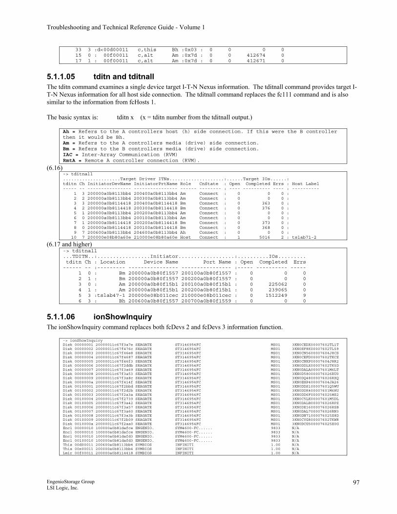
Troubleshooting and Technical Reference Guide - Volume 1
33 3 :d<00d00011 c,this Bh :0x03 : 0 0 0 0 15 0 : 00f00011 c,alt Am :0x7d : 0 0 412674 0 17 1 : 00f00011 c,alt Am :0x7d : 0 0 412671 0
5.1.1.05 tditn and tditnall The tditn command examines a single device target I-T-N Nexus information. The tditnall command provides target I-T-N Nexus information for all host side connection. The tditnall command replaces the fc111 command and is also similar to the information from fcHosts 1. The basic syntax is: tditn x (x = tditn number from the tditnall output.)
Ah = Refers to the A controllers host (h) side connection. If this were the B controller then it would be Bh. Am = Refers to the A controllers media (drive) side connection. Bm = Refers to the B controllers media (drive) side connection. IAC = Inter-Array Communication (RVM) RmtA = Remote A controller connection (RVM).
(6.16) -> tditnall .....................Target Driver ITNs....................:......Target IOs......: tditn Ch InitiatorDevName InitiatorPrtName Role CnState : Open Completed Errs : Host Label ----- -- ---------------- ---------------- ------ -------- : ---- ---------- ---- : ---------- 1 3 200000a0b8113bb4 200400a0b8113bb4 Am Connect : 0 0 0 : 2 2 200000a0b8113bb4 200300a0b8113bb4 Am Connect : 0 0 0 : 3 3 200000a0b8114418 200400a0b8114418 Bm Connect : 0 363 0 : 4 2 200000a0b8114418 200300a0b8114418 Bm Connect : 0 376 0 : 5 1 200000a0b8113bb4 200200a0b8113bb4 Am Connect : 0 0 0 : 6 0 200000a0b8113bb4 200100a0b8113bb4 Am Connect : 0 0 0 : 7 1 200000a0b8114418 200200a0b8114418 Bm Connect : 0 373 0 : 8 0 200000a0b8114418 200100a0b8114418 Bm Connect : 0 368 0 : 9 7 200600a0b8113bb4 204600a0b8113bb4 Ah Connect : 0 0 0 : 10 7 200000e08b80a60e 210000e08b80a60e Host Connect : 1 5016 2 : tslab71-2
(6.17 and higher) -> tditnall ...TDITN..:.................Initiator..................:..........IOs......... tditn Ch : Location Device Name Port Name : Open Completed Errs ------ -- :--------- ---------------- ---------------- :----- ---------- ----- 1 0 : Bm 200000a0b80f1557 200100a0b80f1557 : 0 0 0 2 1 : Bm 200000a0b80f1557 200200a0b80f1557 : 0 0 0 3 0 : Am 200000a0b80f15b1 200100a0b80f15b1 : 0 225062 0 4 1 : Am 200000a0b80f15b1 200200a0b80f15b1 : 0 239065 0 5 3 :tslab47-1 200000e08b011cec 210000e08b011cec : 0 1512249 9 6 3 : Bh 200600a0b80f1557 200700a0b80f1559 : 0 0 0
5.1.1.06 ionShowInquiry The ionShowInquiry command replaces both fcDevs 2 and fcDevs 3 information function.
-> ionShowInquiry Disk 00000001 20000011c67f3a7e SEAGATE ST3146954FC MS01 3KN0CEDX00007602TL1T Disk 00000002 20000011c67f476c SEAGATE ST3146954FC MS01 3KN0EF8K00007602TL59 Disk 00000003 20000011c67f46e8 SEAGATE ST3146954FC MS01 3KN0CN5600007604J8CS Disk 00000004 20000011c67f4687 SEAGATE ST3146954FC MS01 3KN0CEFD00007602TKCZ Disk 00000005 20000011c67f46f3 SEAGATE ST3146954FC MS01 3KN0CNKP00007604J8R2 Disk 00000006 20000011c67f2ddb SEAGATE ST3146954FC MS01 3KN0DDLX00007602TK5D Disk 00000007 20000011c67f3a69 SEAGATE ST3146954FC MS01 3KN0DALA00007601M6LT Disk 00000008 20000011c67f3a53 SEAGATE ST3146954FC MS01 3KN0D580000076026RU0 Disk 00000009 20000011c67f3a8c SEAGATE ST3146954FC MS01 3KN0DQ48000076026RXQ Disk 0000000a 20000011c67f414f SEAGATE ST3146954FC MS01 3KN0EHP400007604JA26 Disk 00100001 20000011c67f2bbd SEAGATE ST3146954FC MS01 3KN0DDS100007601Q5WU Disk 00100002 20000011c67f2d2b SEAGATE ST3146954FC MS01 3KN0DDK400007601M6HU Disk 00100003 20000011c67f2a3a SEAGATE ST3146954FC MS01 3KN0DD6F000076025WS2 Disk 00100004 20000011c67f2739 SEAGATE ST3146954FC MS01 3KN0C5LK00007601M5DL Disk 00100005 20000011c67f3a42 SEAGATE ST3146954FC MS01 3KN0DALB000076026RPZ Disk 00100006 20000011c67f3a57 SEAGATE ST3146954FC MS01 3KN0DE16000076026RSB Disk 00100007 20000011c67f3a60 SEAGATE ST3146954FC MS01 3KN0DAL7000076026RN3 Disk 00100008 20000011c67f3a3b SEAGATE ST3146954FC MS01 3KN0DN71000076025X8D Disk 00100009 20000011c67f2b09 SEAGATE ST3146954FC MS01 3KN0CYG800007602TKWR Disk 0010000a 20000011c67f2aa0 SEAGATE ST3146954FC MS01 3KN0DCG5000076025X0G Encl 00000010 100000a0b81dafce ENGENIO. SYM4600-FC...... 9833 N/A Encl 00000010 100000a0b81dafce ENGENIO. SYM4600-FC...... 9833 N/A Encl 00100010 100000a0b81dafd3 ENGENIO. SYM4600-FC...... 9833 N/A Encl 00100010 100000a0b81dafd3 ENGENIO. SYM4600-FC...... 9833 N/A This 00d00011 200600a0b8113bb4 SYMBIOS INFINITI 1.00 N/A This 00e00011 200000a0b8113bb4 SYMBIOS INFINITI 1.00 N/A Lmir 00f00011 200000a0b8114418 SYMBIOS INFINITI 1.00 N/A
EngenioStorage Group LSI Logic, Inc.
97
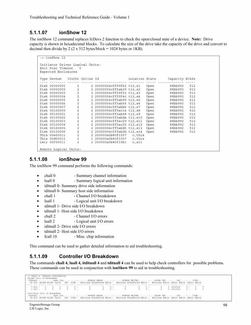
Troubleshooting and Technical Reference Guide - Volume 1
5.1.1.07 ionShow 12 The ionShow 12 command replaces fcDevs 2 function to check the open/closed state of a device. Note: Drive capacity is shown in hexadecimal blocks. To calculate the size of the drive take the capacity of the drive and convert to decimal then divide by 2 (2 x 512 bytes/block = 1024 bytes or 1KB).
-> ionShow 12 Initiator Driver Logical Units: Encl Disc Timeout 0 Expected Enclosures Type Devnum ItnCnt Online Id Location State Capacity BlkSz ---- -------- ------ ------ ---------------- -------- ----- ------------- ----- Disk 00000001 2 2 20000004cff59f62 t12,s1 Open 88bb992 512 Disk 00000002 2 2 20000004cff5ab29 t12,s2 Open 88bb992 512 Disk 00000003 2 2 20000004cff59f52 t12,s3 Open 88bb992 512 Disk 00000004 2 2 20000004cff59f4c t12,s4 Open 88bb992 512 Disk 00000005 2 2 20000004cff5ab99 t12,s5 Open 88bb992 512 Disk 00000006 2 2 20000004cff5ab56 t12,s6 Open 88bb992 512 Disk 00000007 2 2 20000004cff5abb6 t12,s7 Open 88bb992 512 Disk 00100000 2 2 20000004cff5ac14 t12,s8 Open 88bb992 512 Disk 00100001 2 2 20000004cff5ab48 t12,s9 Open 88bb992 512 Disk 00100002 2 2 20000004cff5abda t12,s10 Open 88bb992 512 Disk 00100003 2 2 20000004cff5ac29 t12,s11 Open 88bb992 512 Disk 00100004 2 2 20000004cff5ac25 t12,s12 Open 88bb992 512 Disk 00100005 2 2 20000004cff5abd5 t12,s13 Open 88bb992 512 Disk 00100006 2 2 20000004cff5ab2b t12,s14 Open 88bb992 512 This 00e00011 2 2 200000a0b80f1557 c,this This 00d00011 2 1 200600a0b80f1557 c,this Lmir 00f00011 2 2 200000a0b80f15b1 c,alt Remote Logical Units:
5.1.1.08 ionShow 99 The ionShow 99 command performs the following commands:
• chall 0 - Summary channel information • luall 0 - Summary logical unit information • iditnall 0 - Summary drive side information • tditnall 0 - Summary host side information • chall 1 - Channel I/O breakdown • luall 1 - Logical unit I/O breakdown • iditnall 1 - Drive side I/O breakdown • tditnall 1 - Host side I/O breakdown • chall 2 - Channel I/O errors • luall 2 - Logical unit I/O errors • iditnall 2 - Drive side I/O errors • tditnall 2 - Host side I/O errors • fcall 10 - Misc. chip information
This command can be used to gather detailed information to aid troubleshooting.
5.1.1.09 Controller I/O Breakdown The commands chall 4, luall 4, itditnall 4 and tditnall 4 can be used to help check controllers for possible problems. These commands can be used in conjunction with ionShow 99 to aid in troubleshooting.
-> chall 4 Channel information Target Ctlr IO Breakdown .Channel :...........Open IOs...........:........MIRROR READS........:.......MIRROR WRITES........:....CACHE INV....:....IAC.....:....ICON... Ch H/D :MirRd MirWr CacIn IAC ICON : #Success BlksXfered #Errs : #Success BlksXfered #Errs : #Success #Errs :#Succ #Errs :#Succ #Errs ---- --- :----- ----- ----- ----- ----- :---------- ---------- ----- :---------- ---------- ----- :---------- ----- :----- ----- :----- ----- 0 Drv : 0 0 0 0 0 : 0 0 0 : 0 0 0 : 0 0 :1616106 0 : 0 0 1 Drv : 0 0 0 0 0 : 0 0 0 : 0 0 0 : 0 0 :1611034 0 : 0 0 Initiator Ctlr IO Breakdown .Channel :...........Open IOs...........:........MIRROR READS........:.......MIRROR WRITES........:....CACHE INV....:....IAC.....:....ICON... Ch H/D :MirRd MirWr CacIn IAC ICON : #Success BlksXfered #Errs : #Success BlksXfered #Errs : #Success #Errs :#Succ #Errs :#Succ #Errs ---- --- :----- ----- ----- ----- ----- :---------- ---------- ----- :---------- ---------- ----- :---------- ----- :----- ----- :----- -----
EngenioStorage Group LSI Logic, Inc.
98
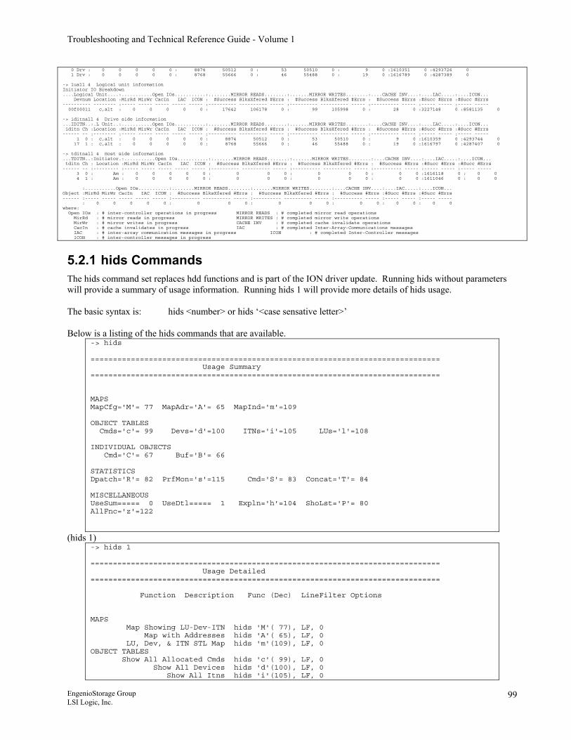
Troubleshooting and Technical Reference Guide - Volume 1
0 Drv : 0 0 0 0 0 : 8874 50512 0 : 53 50510 0 : 9 0 :1610351 0 :4293726 0 1 Drv : 0 0 0 0 0 : 8768 55666 0 : 46 55488 0 : 19 0 :1616789 0 :4287389 0 -> luall 4 Logical unit information Initiator IO Breakdown ....Logical Unit....:...........Open IOs...........:........MIRROR READS........:.......MIRROR WRITES........:....CACHE INV....:....IAC.....:....ICON... Devnum Location :MirRd MirWr CacIn IAC ICON : #Success BlksXfered #Errs : #Success BlksXfered #Errs : #Success #Errs :#Succ #Errs :#Succ #Errs ---------- -------- :----- ----- ----- ----- ----- :---------- ---------- ----- :---------- ---------- ----- :---------- ----- :----- ----- :----- ----- 00f00011 c,alt : 0 0 0 0 0 : 17642 106178 0 : 99 105998 0 : 28 0 :3227148 0 :8581135 0 -> iditnall 4 Drive side information ...IDITN..:.L Unit..:...........Open IOs...........:........MIRROR READS........:.......MIRROR WRITES........:....CACHE INV....:....IAC.....:....ICON... iditn Ch :Location :MirRd MirWr CacIn IAC ICON : #Success BlksXfered #Errs : #Success BlksXfered #Errs : #Success #Errs :#Succ #Errs :#Succ #Errs ------ -- :-------- :----- ----- ----- ----- ----- :---------- ---------- ----- :---------- ---------- ----- :---------- ----- :----- ----- :----- ----- 1 0 : c,alt : 0 0 0 0 0 : 8874 50512 0 : 53 50510 0 : 9 0 :1610359 0 :4293744 0 17 1 : c,alt : 0 0 0 0 0 : 8768 55666 0 : 46 55488 0 : 19 0 :1616797 0 :4287407 0 -> tditnall 4 Host side information ...TDITN..:Initiator.:...........Open IOs...........:........MIRROR READS........:.......MIRROR WRITES........:....CACHE INV....:....IAC.....:....ICON... tditn Ch : Location :MirRd MirWr CacIn IAC ICON : #Success BlksXfered #Errs : #Success BlksXfered #Errs : #Success #Errs :#Succ #Errs :#Succ #Errs ------ -- :--------- :----- ----- ----- ----- ----- :---------- ---------- ----- :---------- ---------- ----- :---------- ----- :----- ----- :----- ----- 3 0 : Am : 0 0 0 0 0 : 0 0 0 : 0 0 0 : 0 0 :1616118 0 : 0 0 4 1 : Am : 0 0 0 0 0 : 0 0 0 : 0 0 0 : 0 0 :1611046 0 : 0 0 :...........Open IOs...........:........MIRROR READS........:.......MIRROR WRITES........:....CACHE INV....:....IAC.....:....ICON... Object :MirRd MirWr CacIn IAC ICON : #Success BlksXfered #Errs : #Success BlksXfered #Errs : #Success #Errs :#Succ #Errs :#Succ #Errs ------ :----- ----- ----- ----- ----- :---------- ---------- ----- :---------- ---------- ----- :---------- ----- :----- ----- :----- ----- : 0 0 0 0 0 : 0 0 0 : 0 0 0 : 0 0 : 0 0 : 0 0 where: Open IOs : # inter-controller operations in progress MIRROR READS : # completed mirror read operations MirRd : # mirror reads in progress MIRROR WRITES : # completed mirror write operations MirWr : # mirror writes in progress CACHE INV : # completed cache invalidate operations CacIn : # cache invalidates in progress IAC : # completed Inter-Array-Communications messages IAC : # inter-array communication messages in progress ICON : # completed Inter-Controller messages ICON : # inter-controller messages in progress
5.2.1 hids Commands The hids command set replaces hdd functions and is part of the ION driver update. Running hids without parameters will provide a summary of usage information. Running hids 1 will provide more details of hids usage. The basic syntax is: hids <number> or hids ‘<case sensative letter>’ Below is a listing of the hids commands that are available.
-> hids ============================================================================== Usage Summary ============================================================================== MAPS MapCfg='M'= 77 MapAdr='A'= 65 MapInd='m'=109 OBJECT TABLES Cmds='c'= 99 Devs='d'=100 ITNs='i'=105 LUs='l'=108 INDIVIDUAL OBJECTS Cmd='C'= 67 Buf='B'= 66 STATISTICS Dpatch='R'= 82 PrfMon='s'=115 Cmd='S'= 83 Concat='T'= 84 MISCELLANEOUS UseSum===== 0 UseDtl===== 1 Expln='h'=104 ShoLst='P'= 80 AllFnc='z'=122
(hids 1) -> hids 1 ============================================================================== Usage Detailed ============================================================================== Function Description Func (Dec) LineFilter Options MAPS Map Showing LU-Dev-ITN hids 'M'( 77), LF, 0 Map with Addresses hids 'A'( 65), LF, 0 LU, Dev, & ITN STL Map hids 'm'(109), LF, 0 OBJECT TABLES Show All Allocated Cmds hids 'c'( 99), LF, 0 Show All Devices hids 'd'(100), LF, 0 Show All Itns hids 'i'(105), LF, 0
EngenioStorage Group LSI Logic, Inc.
99
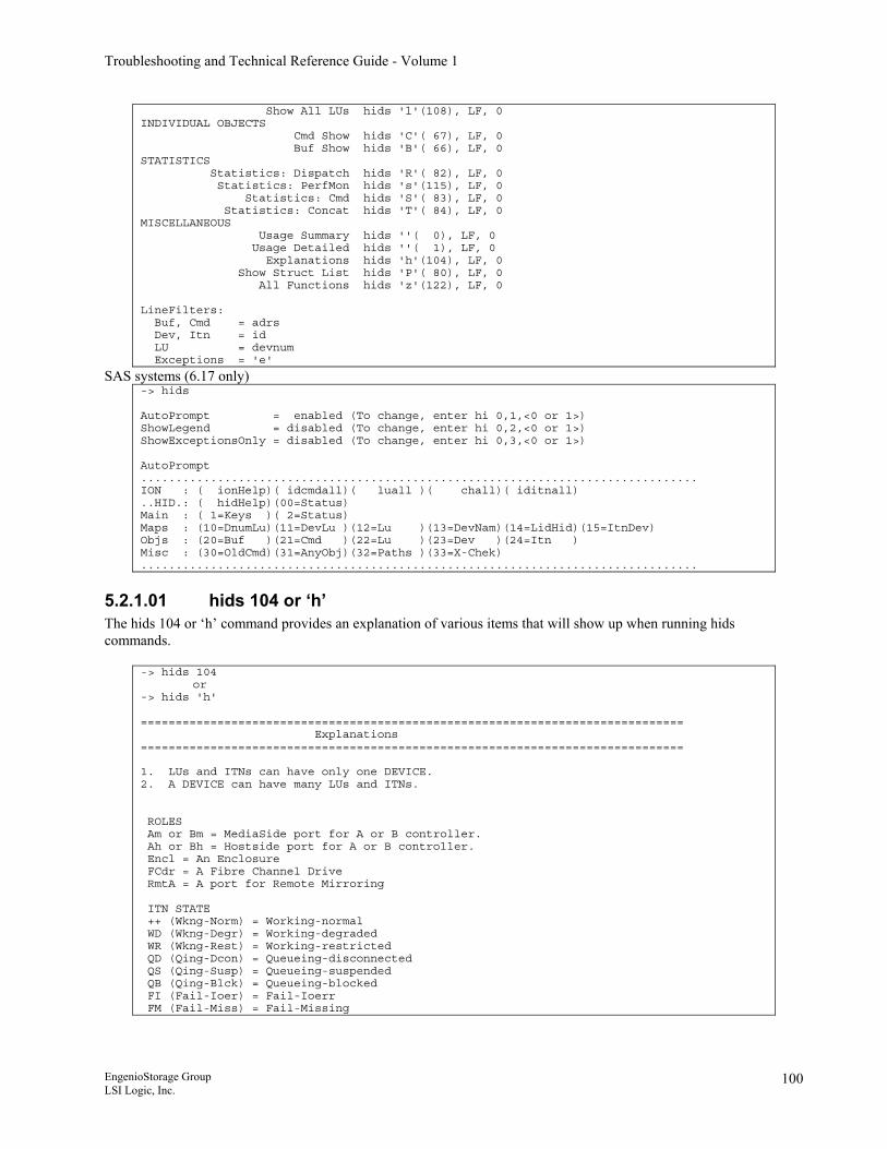
Troubleshooting and Technical Reference Guide - Volume 1
Show All LUs hids 'l'(108), LF, 0 INDIVIDUAL OBJECTS Cmd Show hids 'C'( 67), LF, 0 Buf Show hids 'B'( 66), LF, 0 STATISTICS Statistics: Dispatch hids 'R'( 82), LF, 0 Statistics: PerfMon hids 's'(115), LF, 0 Statistics: Cmd hids 'S'( 83), LF, 0 Statistics: Concat hids 'T'( 84), LF, 0 MISCELLANEOUS Usage Summary hids ''( 0), LF, 0 Usage Detailed hids ''( 1), LF, 0 Explanations hids 'h'(104), LF, 0 Show Struct List hids 'P'( 80), LF, 0 All Functions hids 'z'(122), LF, 0 LineFilters: Buf, Cmd = adrs Dev, Itn = id LU = devnum Exceptions = 'e'
SAS systems (6.17 only) -> hids AutoPrompt = enabled (To change, enter hi 0,1,<0 or 1>) ShowLegend = disabled (To change, enter hi 0,2,<0 or 1>) ShowExceptionsOnly = disabled (To change, enter hi 0,3,<0 or 1>) AutoPrompt ................................................................................ ION : ( ionHelp)( idcmdall)( luall )( chall)( iditnall) ..HID.: ( hidHelp)(00=Status) Main : ( 1=Keys )( 2=Status) Maps : (10=DnumLu)(11=DevLu )(12=Lu )(13=DevNam)(14=LidHid)(15=ItnDev) Objs : (20=Buf )(21=Cmd )(22=Lu )(23=Dev )(24=Itn ) Misc : (30=OldCmd)(31=AnyObj)(32=Paths )(33=X-Chek) ................................................................................
5.2.1.01 hids 104 or ‘h’ The hids 104 or ‘h’ command provides an explanation of various items that will show up when running hids commands.
-> hids 104 or -> hids 'h' ============================================================================== Explanations ============================================================================== 1. LUs and ITNs can have only one DEVICE. 2. A DEVICE can have many LUs and ITNs. ROLES Am or Bm = MediaSide port for A or B controller. Ah or Bh = Hostside port for A or B controller. Encl = An Enclosure FCdr = A Fibre Channel Drive RmtA = A port for Remote Mirroring ITN STATE ++ (Wkng-Norm) = Working-normal WD (Wkng-Degr) = Working-degraded WR (Wkng-Rest) = Working-restricted QD (Qing-Dcon) = Queueing-disconnected QS (Qing-Susp) = Queueing-suspended QB (Qing-Blck) = Queueing-blocked FI (Fail-Ioer) = Fail-Ioerr FM (Fail-Miss) = Fail-Missing
EngenioStorage Group LSI Logic, Inc.
100
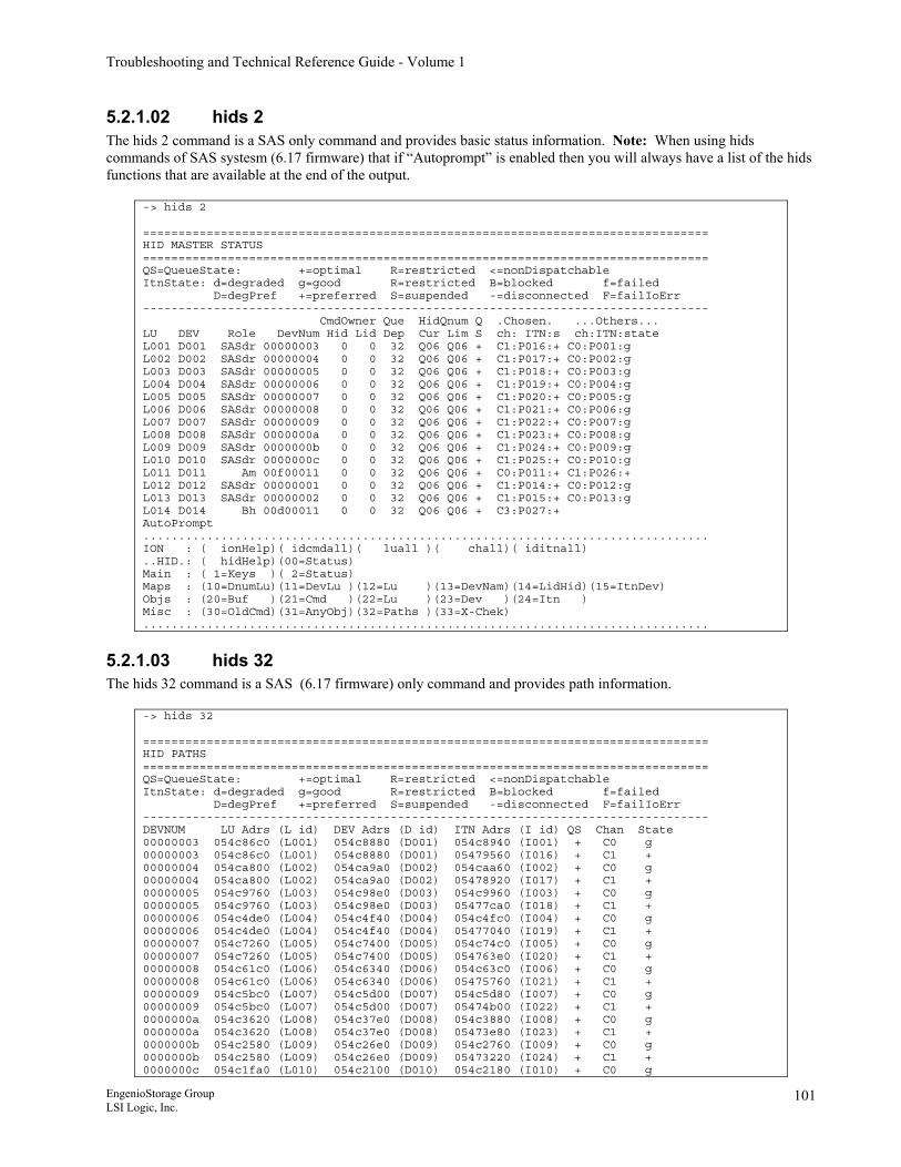
Troubleshooting and Technical Reference Guide - Volume 1
5.2.1.02 hids 2 The hids 2 command is a SAS only command and provides basic status information. Note: When using hids commands of SAS systesm (6.17 firmware) that if “Autoprompt” is enabled then you will always have a list of the hids functions that are available at the end of the output.
-> hids 2 ================================================================================ HID MASTER STATUS ================================================================================ QS=QueueState: +=optimal R=restricted <=nonDispatchable ItnState: d=degraded g=good R=restricted B=blocked f=failed D=degPref +=preferred S=suspended -=disconnected F=failIoErr -------------------------------------------------------------------------------- CmdOwner Que HidQnum Q .Chosen. ...Others... LU DEV Role DevNum Hid Lid Dep Cur Lim S ch: ITN:s ch:ITN:state L001 D001 SASdr 00000003 0 0 32 Q06 Q06 + C1:P016:+ C0:P001:g L002 D002 SASdr 00000004 0 0 32 Q06 Q06 + C1:P017:+ C0:P002:g L003 D003 SASdr 00000005 0 0 32 Q06 Q06 + C1:P018:+ C0:P003:g L004 D004 SASdr 00000006 0 0 32 Q06 Q06 + C1:P019:+ C0:P004:g L005 D005 SASdr 00000007 0 0 32 Q06 Q06 + C1:P020:+ C0:P005:g L006 D006 SASdr 00000008 0 0 32 Q06 Q06 + C1:P021:+ C0:P006:g L007 D007 SASdr 00000009 0 0 32 Q06 Q06 + C1:P022:+ C0:P007:g L008 D008 SASdr 0000000a 0 0 32 Q06 Q06 + C1:P023:+ C0:P008:g L009 D009 SASdr 0000000b 0 0 32 Q06 Q06 + C1:P024:+ C0:P009:g L010 D010 SASdr 0000000c 0 0 32 Q06 Q06 + C1:P025:+ C0:P010:g L011 D011 Am 00f00011 0 0 32 Q06 Q06 + C0:P011:+ C1:P026:+ L012 D012 SASdr 00000001 0 0 32 Q06 Q06 + C1:P014:+ C0:P012:g L013 D013 SASdr 00000002 0 0 32 Q06 Q06 + C1:P015:+ C0:P013:g L014 D014 Bh 00d00011 0 0 32 Q06 Q06 + C3:P027:+ AutoPrompt ................................................................................ ION : ( ionHelp)( idcmdall)( luall )( chall)( iditnall) ..HID.: ( hidHelp)(00=Status) Main : ( 1=Keys )( 2=Status) Maps : (10=DnumLu)(11=DevLu )(12=Lu )(13=DevNam)(14=LidHid)(15=ItnDev) Objs : (20=Buf )(21=Cmd )(22=Lu )(23=Dev )(24=Itn ) Misc : (30=OldCmd)(31=AnyObj)(32=Paths )(33=X-Chek) ................................................................................
5.2.1.03 hids 32 The hids 32 command is a SAS (6.17 firmware) only command and provides path information.
-> hids 32 ================================================================================ HID PATHS ================================================================================ QS=QueueState: +=optimal R=restricted <=nonDispatchable ItnState: d=degraded g=good R=restricted B=blocked f=failed D=degPref +=preferred S=suspended -=disconnected F=failIoErr -------------------------------------------------------------------------------- DEVNUM LU Adrs (L id) DEV Adrs (D id) ITN Adrs (I id) QS Chan State 00000003 054c86c0 (L001) 054c8880 (D001) 054c8940 (I001) + C0 g 00000003 054c86c0 (L001) 054c8880 (D001) 05479560 (I016) + C1 + 00000004 054ca800 (L002) 054ca9a0 (D002) 054caa60 (I002) + C0 g 00000004 054ca800 (L002) 054ca9a0 (D002) 05478920 (I017) + C1 + 00000005 054c9760 (L003) 054c98e0 (D003) 054c9960 (I003) + C0 g 00000005 054c9760 (L003) 054c98e0 (D003) 05477ca0 (I018) + C1 + 00000006 054c4de0 (L004) 054c4f40 (D004) 054c4fc0 (I004) + C0 g 00000006 054c4de0 (L004) 054c4f40 (D004) 05477040 (I019) + C1 + 00000007 054c7260 (L005) 054c7400 (D005) 054c74c0 (I005) + C0 g 00000007 054c7260 (L005) 054c7400 (D005) 054763e0 (I020) + C1 + 00000008 054c61c0 (L006) 054c6340 (D006) 054c63c0 (I006) + C0 g 00000008 054c61c0 (L006) 054c6340 (D006) 05475760 (I021) + C1 + 00000009 054c5bc0 (L007) 054c5d00 (D007) 054c5d80 (I007) + C0 g 00000009 054c5bc0 (L007) 054c5d00 (D007) 05474b00 (I022) + C1 + 0000000a 054c3620 (L008) 054c37e0 (D008) 054c3880 (I008) + C0 g 0000000a 054c3620 (L008) 054c37e0 (D008) 05473e80 (I023) + C1 + 0000000b 054c2580 (L009) 054c26e0 (D009) 054c2760 (I009) + C0 g 0000000b 054c2580 (L009) 054c26e0 (D009) 05473220 (I024) + C1 + 0000000c 054c1fa0 (L010) 054c2100 (D010) 054c2180 (I010) + C0 g
EngenioStorage Group LSI Logic, Inc.
101
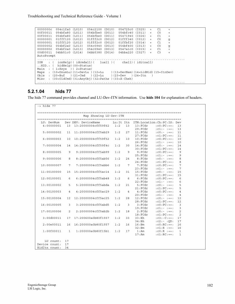
Troubleshooting and Technical Reference Guide - Volume 1
0000000c 054c1fa0 (L010) 054c2100 (D010) 054725c0 (I025) + C1 + 00f00011 054bfa80 (L011) 054bfbe0 (D011) 054bfc40 (I011) + C0 + 00f00011 054bfa80 (L011) 054bfbe0 (D011) 05471940 (I026) + C1 + 00000001 01fff120 (L012) 01fff2c0 (D012) 01fff340 (I012) + C0 g 00000001 01fff120 (L012) 01fff2c0 (D012) 01ffbf20 (I014) + C1 + 00000002 054bf2a0 (L013) 054c0940 (D013) 054bf400 (I013) + C0 g 00000002 054bf2a0 (L013) 054c0940 (D013) 0547a1c0 (I015) + C1 + 00d00011 04bb51c0 (L014) 04bb5380 (D014) 04bba220 (I027) + C3 + AutoPrompt ................................................................................ ION : ( ionHelp)( idcmdall)( luall )( chall)( iditnall) ..HID.: ( hidHelp)(00=Status) Main : ( 1=Keys )( 2=Status) Maps : (10=DnumLu)(11=DevLu )(12=Lu )(13=DevNam)(14=LidHid)(15=ItnDev) Objs : (20=Buf )(21=Cmd )(22=Lu )(23=Dev )(24=Itn ) Misc : (30=OldCmd)(31=AnyObj)(32=Paths )(33=X-Chek) ................................................................................
5.2.1.04 hids 77 The hids 77 command provides channel and LU-Dev-ITN information. Use hids 104 for explanation of headers.
-> hids 77 ============================================================================== Map Showing LU-Dev-ITN ============================================================================== LU: DevNum Dev DEV: DeviceName Lu:It Itn ITN:Location:Ch:PC:IS: Dev 4:00000001 13 13:20000004cff59f62 1:2 13 13:FCdr :c0:PC:++: 13 29:FCdr :c1:- :++: 13 5:00000002 11 11:20000004cff5ab29 1:2 27 11:FCdr :c0:- :++: 11 27:FCdr :c1:PC:++: 11 6:00000003 10 10:20000004cff59f52 1:2 10 10:FCdr :c0:PC:++: 10 26:FCdr :c1:- :++: 10 7:00000004 14 14:20000004cff59f4c 1:2 30 14:FCdr :c0:- :++: 14 30:FCdr :c1:PC:++: 14 8:00000005 9 9:20000004cff5ab99 1:2 9 9:FCdr :c0:PC:++: 9 25:FCdr :c1:- :++: 9 9:00000006 8 8:20000004cff5ab56 1:2 24 8:FCdr :c0:- :++: 8 24:FCdr :c1:PC:++: 8 10:00000007 7 7:20000004cff5abb6 1:2 7 7:FCdr :c0:PC:++: 7 23:FCdr :c1:- :++: 7 11:00100000 15 15:20000004cff5ac14 1:2 31 15:FCdr :c0:- :++: 15 31:FCdr :c1:PC:++: 15 12:00100001 6 6:20000004cff5ab48 1:2 6 6:FCdr :c0:PC:++: 6 22:FCdr :c1:- :++: 6 13:00100002 5 5:20000004cff5abda 1:2 21 5:FCdr :c0:- :++: 5 21:FCdr :c1:PC:++: 5 14:00100003 4 4:20000004cff5ac29 1:2 4 4:FCdr :c0:PC:++: 4 20:FCdr :c1:- :++: 4 15:00100004 12 12:20000004cff5ac25 1:2 28 12:FCdr :c0:- :++: 12 28:FCdr :c1:PC:++: 12 16:00100005 3 3:20000004cff5abd5 1:2 3 3:FCdr :c0:PC:++: 3 19:FCdr :c1:- :++: 3 17:00100006 2 2:20000004cff5ab2b 1:2 18 2:FCdr :c0:- :++: 2 18:FCdr :c1:PC:++: 2 3:00d00011 17 17:200600a0b80f1557 1:2 33 33:Bh :c3:-C:++: 17 34:Bh :c2:- :QD: 17 2:00e00011 16 16:200000a0b80f1557 1:2 16 16:Bm :c0:RC:++: 16 32:Bm :c1:R :++: 16 1:00f00011 1 1:200000a0b80f15b1 1:2 17 1:Am :c0:R :++: 1 17:Am :c1:RC:++: 1 LU count: 17 Device count: 17 HidItn count: 34
EngenioStorage Group LSI Logic, Inc.
102
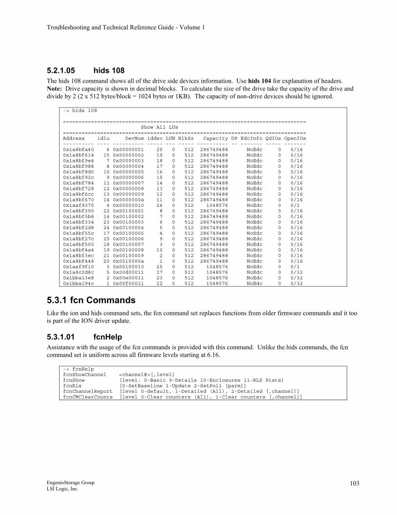
Troubleshooting and Technical Reference Guide - Volume 1
5.2.1.05 hids 108 The hids 108 command shows all of the drive side devices information. Use hids 104 for explanation of headers. Note: Drive capacity is shown in decimal blocks. To calculate the size of the drive take the capacity of the drive and divide by 2 (2 x 512 bytes/block = 1024 bytes or 1KB). The capacity of non-drive devices should be ignored.
-> hids 108 ============================================================================== Show All LUs ============================================================================== Address idlu DevNum iddev LUN BlkSz Capacity DP EdcInfo QdIOs OpenIOs ---------- ---- ---------- ----- --- ----- ---------- -- ------- ----- ------- 0x1a8bfa40 6 0x00000001 20 0 512 286749488 NoEdc 0 0/16 0x1a8bf614 15 0x00000002 19 0 512 286749488 NoEdc 0 0/16 0x1a8bf9e4 7 0x00000003 18 0 512 286749488 NoEdc 0 0/16 0x1a8bf988 8 0x00000004 17 0 512 286749488 NoEdc 0 0/16 0x1a8bf8d0 10 0x00000005 16 0 512 286749488 NoEdc 0 0/16 0x1a8bf92c 9 0x00000006 15 0 512 286749488 NoEdc 0 0/16 0x1a8bf784 11 0x00000007 14 0 512 286749488 NoEdc 0 0/16 0x1a8bf728 12 0x00000008 13 0 512 286749488 NoEdc 0 0/16 0x1a8bf6cc 13 0x00000009 12 0 512 286749488 NoEdc 0 0/16 0x1a8bf670 14 0x0000000a 11 0 512 286749488 NoEdc 0 0/16 0x1aaf9370 4 0x00000010 26 0 512 1048576 NoEdc 0 0/1 0x1a8bf390 22 0x00100001 8 0 512 286749488 NoEdc 0 0/16 0x1a8bf5b8 16 0x00100002 7 0 512 286749488 NoEdc 0 0/16 0x1a8bf334 23 0x00100003 6 0 512 286749488 NoEdc 0 0/16 0x1a8bf2d8 24 0x00100004 5 0 512 286749488 NoEdc 0 0/16 0x1a8bf55c 17 0x00100005 4 0 512 286749488 NoEdc 0 0/16 0x1a8bf27c 25 0x00100006 9 0 512 286749488 NoEdc 0 0/16 0x1a8bf500 18 0x00100007 3 0 512 286749488 NoEdc 0 0/16 0x1a8bf4a4 19 0x00100008 10 0 512 286749488 NoEdc 0 0/16 0x1a8bf3ec 21 0x00100009 2 0 512 286749488 NoEdc 0 0/16 0x1a8bf448 20 0x0010000a 1 0 512 286749488 NoEdc 0 0/16 0x1aaf9f10 3 0x00100010 25 0 512 1048576 NoEdc 0 0/1 0x1a8c2d8c 5 0x00d00011 27 0 512 1048576 NoEdc 0 0/32 0x1bba13e8 2 0x00e00011 23 0 512 1048576 NoEdc 0 0/32 0x1bba194c 1 0x00f00011 22 0 512 1048576 NoEdc 0 0/32
5.3.1 fcn Commands Like the ion and hids command sets, the fcn command set replaces functions from older firmware commands and it too is part of the ION driver update.
5.3.1.01 fcnHelp Assistance with the usage of the fcn commands is provided with this command. Unlike the hids commands, the fcn command set is uniform across all firmware levels starting at 6.16.
-> fcnHelp fcnShowChannel <channel#>[,level] fcnShow [level: 0-Basic 9-Details 10-Enclosures 11-RLS Stats] fcnRls [0-SetBaseline 1-Update 2-SetPoll [parm]] fcnChannelReport [level 0-default, 1-Detailed (All), 2-Detailed [,channel]] fcnCMClearCounts [level 0-Clear counters (All), 1-Clear counters [,channel]]
EngenioStorage Group LSI Logic, Inc.
103
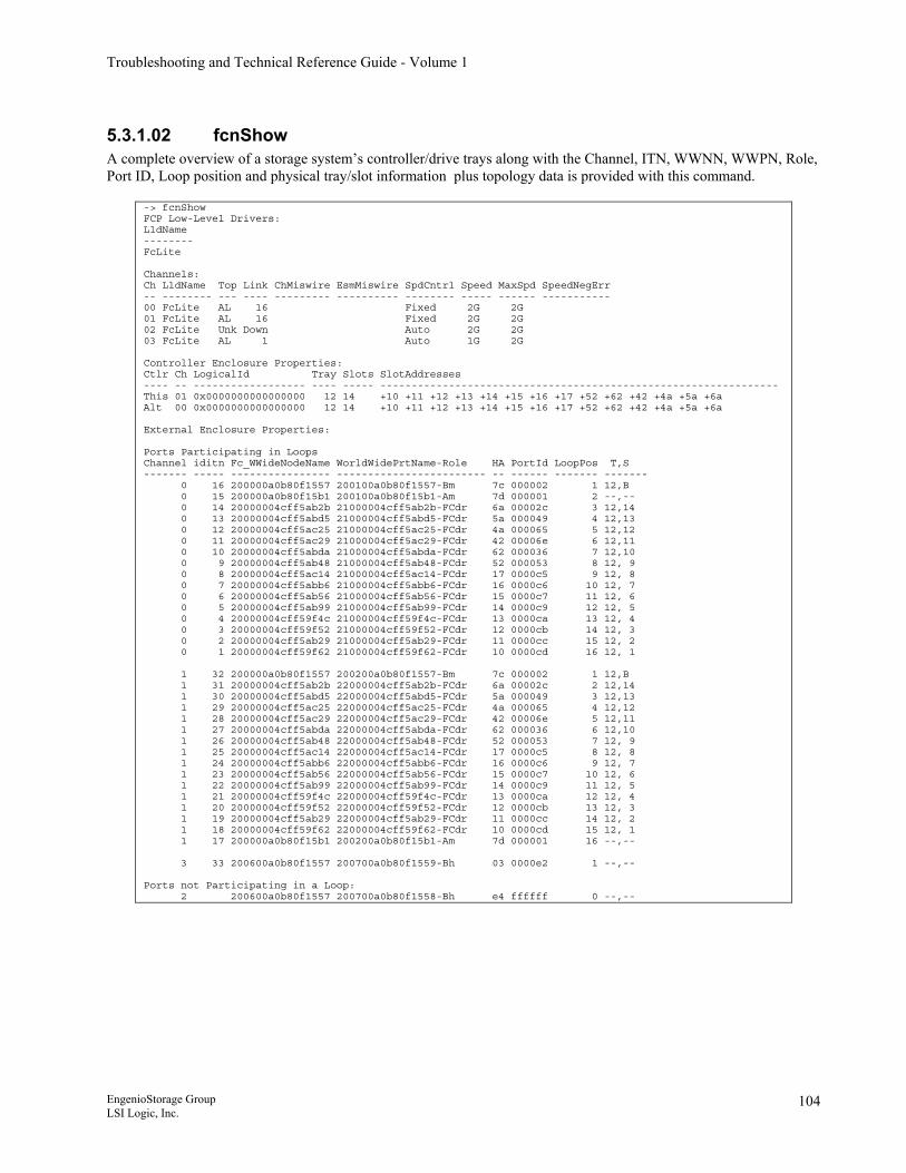
Troubleshooting and Technical Reference Guide - Volume 1
5.3.1.02 fcnShow A complete overview of a storage system’s controller/drive trays along with the Channel, ITN, WWNN, WWPN, Role, Port ID, Loop position and physical tray/slot information plus topology data is provided with this command.
-> fcnShow FCP Low-Level Drivers: LldName -------- FcLite Channels: Ch LldName Top Link ChMiswire EsmMiswire SpdCntrl Speed MaxSpd SpeedNegErr -- -------- --- ---- --------- ---------- -------- ----- ------ ----------- 00 FcLite AL 16 Fixed 2G 2G 01 FcLite AL 16 Fixed 2G 2G 02 FcLite Unk Down Auto 2G 2G 03 FcLite AL 1 Auto 1G 2G Controller Enclosure Properties: Ctlr Ch LogicalId Tray Slots SlotAddresses ---- -- ------------------ ---- ----- ---------------------------------------------------------------- This 01 0x0000000000000000 12 14 +10 +11 +12 +13 +14 +15 +16 +17 +52 +62 +42 +4a +5a +6a Alt 00 0x0000000000000000 12 14 +10 +11 +12 +13 +14 +15 +16 +17 +52 +62 +42 +4a +5a +6a External Enclosure Properties: Ports Participating in Loops Channel iditn Fc_WWideNodeName WorldWidePrtName-Role HA PortId LoopPos T,S ------- ----- ---------------- ------------------------ -- ------ ------- ------- 0 16 200000a0b80f1557 200100a0b80f1557-Bm 7c 000002 1 12,B 0 15 200000a0b80f15b1 200100a0b80f15b1-Am 7d 000001 2 --,-- 0 14 20000004cff5ab2b 21000004cff5ab2b-FCdr 6a 00002c 3 12,14 0 13 20000004cff5abd5 21000004cff5abd5-FCdr 5a 000049 4 12,13 0 12 20000004cff5ac25 21000004cff5ac25-FCdr 4a 000065 5 12,12 0 11 20000004cff5ac29 21000004cff5ac29-FCdr 42 00006e 6 12,11 0 10 20000004cff5abda 21000004cff5abda-FCdr 62 000036 7 12,10 0 9 20000004cff5ab48 21000004cff5ab48-FCdr 52 000053 8 12, 9 0 8 20000004cff5ac14 21000004cff5ac14-FCdr 17 0000c5 9 12, 8 0 7 20000004cff5abb6 21000004cff5abb6-FCdr 16 0000c6 10 12, 7 0 6 20000004cff5ab56 21000004cff5ab56-FCdr 15 0000c7 11 12, 6 0 5 20000004cff5ab99 21000004cff5ab99-FCdr 14 0000c9 12 12, 5 0 4 20000004cff59f4c 21000004cff59f4c-FCdr 13 0000ca 13 12, 4 0 3 20000004cff59f52 21000004cff59f52-FCdr 12 0000cb 14 12, 3 0 2 20000004cff5ab29 21000004cff5ab29-FCdr 11 0000cc 15 12, 2 0 1 20000004cff59f62 21000004cff59f62-FCdr 10 0000cd 16 12, 1 1 32 200000a0b80f1557 200200a0b80f1557-Bm 7c 000002 1 12,B 1 31 20000004cff5ab2b 22000004cff5ab2b-FCdr 6a 00002c 2 12,14 1 30 20000004cff5abd5 22000004cff5abd5-FCdr 5a 000049 3 12,13 1 29 20000004cff5ac25 22000004cff5ac25-FCdr 4a 000065 4 12,12 1 28 20000004cff5ac29 22000004cff5ac29-FCdr 42 00006e 5 12,11 1 27 20000004cff5abda 22000004cff5abda-FCdr 62 000036 6 12,10 1 26 20000004cff5ab48 22000004cff5ab48-FCdr 52 000053 7 12, 9 1 25 20000004cff5ac14 22000004cff5ac14-FCdr 17 0000c5 8 12, 8 1 24 20000004cff5abb6 22000004cff5abb6-FCdr 16 0000c6 9 12, 7 1 23 20000004cff5ab56 22000004cff5ab56-FCdr 15 0000c7 10 12, 6 1 22 20000004cff5ab99 22000004cff5ab99-FCdr 14 0000c9 11 12, 5 1 21 20000004cff59f4c 22000004cff59f4c-FCdr 13 0000ca 12 12, 4 1 20 20000004cff59f52 22000004cff59f52-FCdr 12 0000cb 13 12, 3 1 19 20000004cff5ab29 22000004cff5ab29-FCdr 11 0000cc 14 12, 2 1 18 20000004cff59f62 22000004cff59f62-FCdr 10 0000cd 15 12, 1 1 17 200000a0b80f15b1 200200a0b80f15b1-Am 7d 000001 16 --,-- 3 33 200600a0b80f1557 200700a0b80f1559-Bh 03 0000e2 1 --,-- Ports not Participating in a Loop: 2 200600a0b80f1557 200700a0b80f1558-Bh e4 ffffff 0 --,--
EngenioStorage Group LSI Logic, Inc.
104
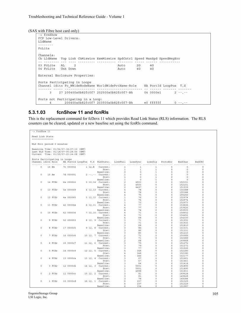
Troubleshooting and Technical Reference Guide - Volume 1
(SAS with Fibre host card only) -> fcnShow FCP Low-Level Drivers: LldName -------- FcLite Channels: Ch LldName Top Link ChMiswire EsmMiswire SpdCntrl Speed MaxSpd SpeedNegErr -- -------- --- ---- --------- ---------- -------- ----- ------ ----------- 03 FcLite AL 2 Auto 2G 4G 04 FcLite Unk Down Auto 4G 4G External Enclosure Properties: Ports Participating in Loops Channel iditn Fc_WWideNodeName WorldWidePrtName-Role HA PortId LoopPos T,S ------- ----- ---------------- ------------------------ -- ------ ------- ------- 3 27 200400a0b82fc0f7 202500a0b82fc0f7-Bh 04 0000e1 2 --,-- Ports not Participating in a Loop: 4 200400a0b82fc0f7 203500a0b82fc0f7-Bh e0 ffffff 0 --,--
5.3.1.03 fcnShow 11 and fcnRls This is the replacement command for fcDevs 11 which provides Read Link Status (RLS) information. The RLS counters can be cleared, updated or a new baseline set using the fcnRls command.
-> fcnShow 11 Read Link Stats =============== RLS Poll period 0 minutes BaseLine Time: 01/04/07-18:27:10 (GMT) Last RLS Time: 01/18/07-05:28:50 (GMT) Current Time: 01/29/07-22:24:08 (GMT) Ports Participating in Loops Channel iditn Role HA PortId LoopPos T,S RLSStats: LinkFail LossSync LossSig ProtoErr BadChar BadCRC ------- ----- ------- -- ------ ------- ----- --------: ---------- ---------- ---------- ---------- ---------- ----------- 0 16 Bm 7c 000002 1 12,B Current: 1 1 1 0 0 0 Prev: 1 1 1 0 0 0 Baseline: 0 0 1 0 0 0 0 15 Am 7d 000001 2 --,-- Current: 1 0 1 0 0 0 Prev: 1 0 1 0 0 0 Baseline: 1 0 1 0 0 0 0 14 FCdr 6a 00002c 3 12,14 Current: 2 4503 0 0 152151 0 Prev: 2 4503 0 0 152151 0 Baseline: 2 4497 0 0 151539 0 0 13 FCdr 5a 000049 4 12,13 Current: 4 78 0 0 155388 0 Prev: 4 78 0 0 155388 0 Baseline: 4 75 0 0 155266 0 0 12 FCdr 4a 000065 5 12,12 Current: 1 76 0 0 152974 0 Prev: 1 76 0 0 152974 0 Baseline: 1 73 0 0 152973 0 0 11 FCdr 42 00006e 6 12,11 Current: 4 77 0 0 153626 0 Prev: 4 77 0 0 153626 0 Baseline: 4 74 0 0 153503 0 0 10 FCdr 62 000036 7 12,10 Current: 4 71 0 0 154452 0 Prev: 4 71 0 0 154452 0 Baseline: 4 68 0 0 154330 0 0 9 FCdr 52 000053 8 12, 9 Current: 3 71 0 0 151932 0 Prev: 3 71 0 0 151932 0 Baseline: 3 68 0 0 151810 0 0 8 FCdr 17 0000c5 9 12, 8 Current: 3 86 0 0 151331 0 Prev: 3 86 0 0 151331 0 Baseline: 3 83 0 0 151210 0 0 7 FCdr 16 0000c6 10 12, 7 Current: 2 71 0 0 150089 0 Prev: 2 71 0 0 150089 0 Baseline: 2 68 0 0 149968 0 0 6 FCdr 15 0000c7 11 12, 6 Current: 3 79 0 0 151272 0 Prev: 3 79 0 0 151272 0 Baseline: 3 77 0 0 151026 0 0 5 FCdr 14 0000c9 12 12, 5 Current: 4 348 0 0 152180 0 Prev: 4 348 0 0 152180 0 Baseline: 4 346 0 0 152177 0 0 4 FCdr 13 0000ca 13 12, 4 Current: 3 67 0 0 151661 0 Prev: 3 67 0 0 151661 0 Baseline: 3 64 0 0 151418 0 0 3 FCdr 12 0000cb 14 12, 3 Current: 1 5001 0 0 151895 0 Prev: 1 5001 0 0 151895 0 Baseline: 1 4998 0 0 151651 0 0 2 FCdr 11 0000cc 15 12, 2 Current: 3 81 0 0 149628 0 Prev: 3 81 0 0 149628 0 Baseline: 3 78 0 0 149384 0 0 1 FCdr 10 0000cd 16 12, 1 Current: 6 157 0 0 151329 0 Prev: 6 157 0 0 151329 0 Baseline: 6 154 0 0 151087 0
EngenioStorage Group LSI Logic, Inc.
105
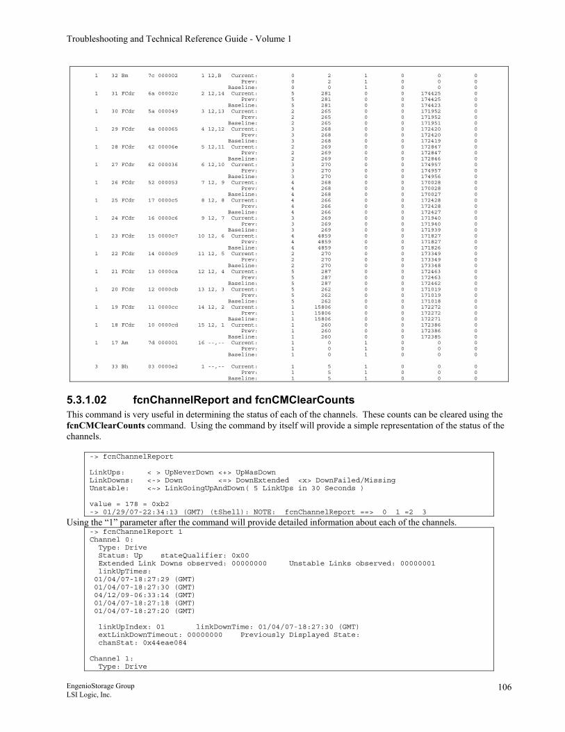
Troubleshooting and Technical Reference Guide - Volume 1
1 32 Bm 7c 000002 1 12,B Current: 0 2 1 0 0 0 Prev: 0 2 1 0 0 0 Baseline: 0 0 1 0 0 0 1 31 FCdr 6a 00002c 2 12,14 Current: 5 281 0 0 174425 0 Prev: 5 281 0 0 174425 0 Baseline: 5 281 0 0 174423 0 1 30 FCdr 5a 000049 3 12,13 Current: 2 265 0 0 171952 0 Prev: 2 265 0 0 171952 0 Baseline: 2 265 0 0 171951 0 1 29 FCdr 4a 000065 4 12,12 Current: 3 268 0 0 172420 0 Prev: 3 268 0 0 172420 0 Baseline: 3 268 0 0 172419 0 1 28 FCdr 42 00006e 5 12,11 Current: 2 269 0 0 172847 0 Prev: 2 269 0 0 172847 0 Baseline: 2 269 0 0 172846 0 1 27 FCdr 62 000036 6 12,10 Current: 3 270 0 0 174957 0 Prev: 3 270 0 0 174957 0 Baseline: 3 270 0 0 174956 0 1 26 FCdr 52 000053 7 12, 9 Current: 4 268 0 0 170028 0 Prev: 4 268 0 0 170028 0 Baseline: 4 268 0 0 170027 0 1 25 FCdr 17 0000c5 8 12, 8 Current: 4 266 0 0 172428 0 Prev: 4 266 0 0 172428 0 Baseline: 4 266 0 0 172427 0 1 24 FCdr 16 0000c6 9 12, 7 Current: 3 269 0 0 171940 0 Prev: 3 269 0 0 171940 0 Baseline: 3 269 0 0 171939 0 1 23 FCdr 15 0000c7 10 12, 6 Current: 4 4859 0 0 171827 0 Prev: 4 4859 0 0 171827 0 Baseline: 4 4859 0 0 171826 0 1 22 FCdr 14 0000c9 11 12, 5 Current: 2 270 0 0 173349 0 Prev: 2 270 0 0 173349 0 Baseline: 2 270 0 0 173348 0 1 21 FCdr 13 0000ca 12 12, 4 Current: 5 287 0 0 172463 0 Prev: 5 287 0 0 172463 0 Baseline: 5 287 0 0 172462 0 1 20 FCdr 12 0000cb 13 12, 3 Current: 5 262 0 0 171019 0 Prev: 5 262 0 0 171019 0 Baseline: 5 262 0 0 171018 0 1 19 FCdr 11 0000cc 14 12, 2 Current: 1 15806 0 0 172272 0 Prev: 1 15806 0 0 172272 0 Baseline: 1 15806 0 0 172271 0 1 18 FCdr 10 0000cd 15 12, 1 Current: 1 260 0 0 172386 0 Prev: 1 260 0 0 172386 0 Baseline: 1 260 0 0 172385 0 1 17 Am 7d 000001 16 --,-- Current: 1 0 1 0 0 0 Prev: 1 0 1 0 0 0 Baseline: 1 0 1 0 0 0 3 33 Bh 03 0000e2 1 --,-- Current: 1 5 1 0 0 0 Prev: 1 5 1 0 0 0 Baseline: 1 5 1 0 0 0
5.3.1.02 fcnChannelReport and fcnCMClearCounts This command is very useful in determining the status of each of the channels. These counts can be cleared using the fcnCMClearCounts command. Using the command by itself will provide a simple representation of the status of the channels.
-> fcnChannelReport LinkUps: < > UpNeverDown <+> UpWasDown LinkDowns: <-> Down <=> DownExtended <x> DownFailed/Missing Unstable: <~> LinkGoingUpAndDown( 5 LinkUps in 30 Seconds ) value = 178 = 0xb2 -> 01/29/07-22:34:13 (GMT) (tShell): NOTE: fcnChannelReport ==> 0 1 =2 3
Using the “1” parameter after the command will provide detailed information about each of the channels. -> fcnChannelReport 1 Channel 0: Type: Drive Status: Up stateQualifier: 0x00 Extended Link Downs observed: 00000000 Unstable Links observed: 00000001 linkUpTimes: 01/04/07-18:27:29 (GMT) 01/04/07-18:27:30 (GMT) 04/12/09-06:33:14 (GMT) 01/04/07-18:27:18 (GMT) 01/04/07-18:27:20 (GMT) linkUpIndex: 01 linkDownTime: 01/04/07-18:27:30 (GMT) extLinkDownTimeout: 00000000 Previously Displayed State: chanStat: 0x44eae084 Channel 1: Type: Drive
EngenioStorage Group LSI Logic, Inc.
106
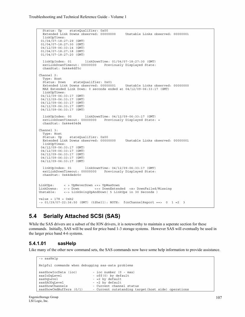
Troubleshooting and Technical Reference Guide - Volume 1
Status: Up stateQualifier: 0x00 Extended Link Downs observed: 00000000 Unstable Links observed: 00000001 linkUpTimes: 01/04/07-18:27:29 (GMT) 01/04/07-18:27:30 (GMT) 04/12/09-06:33:14 (GMT) 01/04/07-18:27:18 (GMT) 01/04/07-18:27:20 (GMT) linkUpIndex: 01 linkDownTime: 01/04/07-18:27:30 (GMT) extLinkDownTimeout: 00000000 Previously Displayed State: chanStat: 0x44e8df5c Channel 2: Type: Host Status: Down stateQualifier: 0x01 Extended Link Downs observed: 00000001 Unstable Links observed: 00000000 MAX Extended Link Down: 0 seconds ended at 04/12/09-06:33:17 (GMT) linkUpTimes: 04/12/09-06:33:17 (GMT) 04/12/09-06:33:17 (GMT) 04/12/09-06:33:17 (GMT) 04/12/09-06:33:17 (GMT) 04/12/09-06:33:17 (GMT) linkUpIndex: 00 linkDownTime: 04/12/09-06:33:17 (GMT) extLinkDownTimeout: 00000000 Previously Displayed State: = chanStat: 0x44e404d4 Channel 3: Type: Host Status: Up stateQualifier: 0x00 Extended Link Downs observed: 00000000 Unstable Links observed: 00000001 linkUpTimes: 04/12/09-06:33:17 (GMT) 04/12/09-06:33:17 (GMT) 04/12/09-06:33:17 (GMT) 04/12/09-06:33:17 (GMT) 04/12/09-06:33:17 (GMT) linkUpIndex: 01 linkDownTime: 04/12/09-06:33:17 (GMT) extLinkDownTimeout: 00000000 Previously Displayed State: chanStat: 0x44dedc0c LinkUps: < > UpNeverDown <+> UpWasDown LinkDowns: <-> Down <=> DownExtended <x> DownFailed/Missing Unstable: <~> LinkGoingUpAndDown( 5 LinkUps in 30 Seconds ) value = 178 = 0xb2 -> 01/29/07-22:36:50 (GMT) (tShell): NOTE: fcnChannelReport ==> 0 1 =2 3
5.4 Serially Attached SCSI (SAS) While the SAS drivers are a subset of the ION drivers, it is noteworthy to maintain a seperate section for these commands. Initially, SAS will be used for price band 1-3 storage systems. However SAS will eventually be used in the larger price band 4-6 systems.
5.4.1.01 sasHelp Like many of the other new command sets, the SAS commands now have some help information to provide assistance.
-> sasHelp Helpful commands when debugging sas-sata problems sasShowIocData (ioc) - ioc number (0 - max) sasIoDqLevel - off(0) by default sasDqLevel - =2 by default sasSAODqLevel - =2 by default sasShowChannels - Current channel status sasShowCmdBuffers (0/1) - Current outstanding target(host side) operations
EngenioStorage Group LSI Logic, Inc.
107
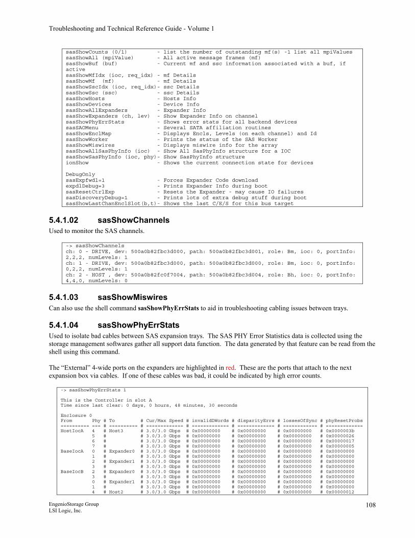
Troubleshooting and Technical Reference Guide - Volume 1
sasShowCounts (0/1) - list the number of outstanding mf(s) -1 list all mpiValues sasShowAll (mpiValue) - All active message frames (mf) sasShowBuf (buf) - Current mf and ssc information associated with a buf, if active sasShowMfIdx (ioc, req_idx) - mf Details sasShowMf (mf) - mf Details sasShowSscIdx (ioc, req_idx)- ssc Details sasShowSsc (ssc) - ssc Details sasShowHosts - Hosts Info sasShowDevices - Device Info sasShowAllExpanders - Expander Info sasShowExpanders (ch, lev) - Show Expander Info on channel sasShowPhyErrStats - Shows error stats for all backend devices sasSAOMenu - Several SATA affiliation routines sasShowEnclMap - Displays Encls, Levels (on each channel) and Id sasShowWorker - Prints the status of the SAS Worker sasShowMiswires - Displays miswire info for the array sasShowAllSasPhyInfo (ioc) - Show All SasPhyInfo structure for a IOC sasShowSasPhyInfo (ioc, phy)- Show SasPhyInfo structure ionShow - Shows the current connection state for devices DebugOnly sasExpfwdl=1 - Forces Expander Code download expdlDebug=3 - Prints Expander Info during boot sasResetCtrlExp - Resets the Expander - may cause IO failures sasDiscoveryDebug=1 - Prints lots of extra debug stuff during boot sasShowLastChanEnclSlot(b,t)- Shows the last C/E/S for this bus target
5.4.1.02 sasShowChannels Used to monitor the SAS channels.
-> sasShowChannels ch: 0 - DRIVE, dev: 500a0b82fbc3d000, path: 500a0b82fbc3d001, role: Bm, ioc: 0, portInfo: 2,2,2, numLevels: 1 ch: 1 - DRIVE, dev: 500a0b82fbc3d000, path: 500a0b82fbc3d000, role: Bm, ioc: 0, portInfo: 0,2,2, numLevels: 1 ch: 2 - HOST , dev: 500a0b82fc0f7004, path: 500a0b82fbc3d004, role: Bh, ioc: 0, portInfo: 4,4,0, numLevels: 0
5.4.1.03 sasShowMiswires Can also use the shell command sasShowPhyErrStats to aid in troubleshooting cabling issues between trays.
5.4.1.04 sasShowPhyErrStats Used to isolate bad cables between SAS expansion trays. The SAS PHY Error Statistics data is collected using the storage management softwares gather all support data function. The data generated by that feature can be read from the shell using this command. The “External” 4-wide ports on the expanders are highlighted in red. These are the ports that attach to the next expansion box via cables. If one of these cables was bad, it could be indicated by high error counts.
-> sasShowPhyErrStats 1 This is the Controller in slot A Time since last clear: 0 days, 0 hours, 48 minutes, 30 seconds Enclosure 0 From Phy # To # Cur/Max Speed # invalidDWords # disparityErrs # lossesOfSync # phyResetProbs ========== === # ========== # ============= # ============= # ============= # ============ # ============= HostIocA 4 # Host3 # 3.0/3.0 Gbps # 0x00000000 # 0x00000000 # 0x00000000 # 0x0000003b 5 # # 3.0/3.0 Gbps # 0x00000000 # 0x00000000 # 0x00000000 # 0x00000026 6 # # 3.0/3.0 Gbps # 0x00000000 # 0x00000000 # 0x00000000 # 0x00000017 7 # # 3.0/3.0 Gbps # 0x00000000 # 0x00000000 # 0x00000000 # 0x00000005 BaseIocA 0 # Expander0 # 3.0/3.0 Gbps # 0x00000000 # 0x00000000 # 0x00000000 # 0x00000000 1 # # 3.0/3.0 Gbps # 0x00000000 # 0x00000000 # 0x00000000 # 0x00000000 2 # Expander1 # 3.0/3.0 Gbps # 0x00000000 # 0x00000000 # 0x00000000 # 0x00000000 3 # # 3.0/3.0 Gbps # 0x00000000 # 0x00000000 # 0x00000000 # 0x00000000 BaseIocB 2 # Expander0 # 3.0/3.0 Gbps # 0x00000000 # 0x00000000 # 0x00000000 # 0x00000000 3 # # 3.0/3.0 Gbps # 0x00000000 # 0x00000000 # 0x00000000 # 0x00000000 0 # Expander1 # 3.0/3.0 Gbps # 0x00000000 # 0x00000000 # 0x00000000 # 0x00000000 1 # # 3.0/3.0 Gbps # 0x00000000 # 0x00000000 # 0x00000000 # 0x00000000 4 # Host2 # 3.0/3.0 Gbps # 0x00000000 # 0x00000000 # 0x00000000 # 0x00000012
EngenioStorage Group LSI Logic, Inc.
108
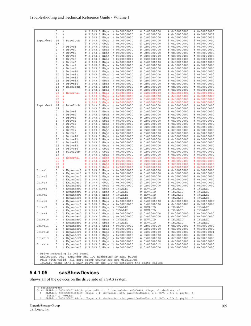
Troubleshooting and Technical Reference Guide - Volume 1
5 # # 3.0/3.0 Gbps # 0x00000000 # 0x00000000 # 0x00000000 # 0x00000000 6 # # 3.0/3.0 Gbps # 0x00000000 # 0x00000000 # 0x00000000 # 0x00000037 7 # # 3.0/3.0 Gbps # 0x00000000 # 0x00000000 # 0x00000000 # 0x00000028 Expander0 16 # BaseIocA # 3.0/3.0 Gbps # 0x00000000 # 0x00000000 # 0x00000000 # 0x00000000 17 # # 3.0/3.0 Gbps # 0x00000000 # 0x00000000 # 0x00000000 # 0x00000000 0 # Drive1 # 3.0/3.0 Gbps # 0x00000000 # 0x00000000 # 0x00000000 # 0x00000000 1 # Drive2 # 3.0/3.0 Gbps # 0x00000000 # 0x00000000 # 0x00000000 # 0x00000000 2 # Drive3 # 3.0/3.0 Gbps # 0x00000000 # 0x00000000 # 0x00000000 # 0x00000000 3 # Drive4 # 3.0/3.0 Gbps # 0x00000000 # 0x00000000 # 0x00000000 # 0x00000000 4 # Drive5 # 3.0/3.0 Gbps # 0x00000000 # 0x00000000 # 0x00000000 # 0x00000000 5 # Drive6 # 3.0/3.0 Gbps # 0x00000000 # 0x00000000 # 0x00000000 # 0x00000000 6 # Drive7 # 3.0/3.0 Gbps # 0x00000000 # 0x00000000 # 0x00000000 # 0x00000000 7 # Drive8 # 3.0/3.0 Gbps # 0x00000000 # 0x00000000 # 0x00000000 # 0x00000000 9 # Drive10 # 3.0/3.0 Gbps # 0x00000000 # 0x00000000 # 0x00000000 # 0x00000000 10 # Drive11 # 3.0/3.0 Gbps # 0x00000000 # 0x00000000 # 0x00000000 # 0x00000000 11 # Drive12 # 3.0/3.0 Gbps # 0x00000000 # 0x00000000 # 0x00000000 # 0x00000000 12 # Drive13 # 3.0/3.0 Gbps # 0x00000000 # 0x00000000 # 0x00000000 # 0x00000000 13 # Drive14 # 3.0/3.0 Gbps # 0x00000000 # 0x00000000 # 0x00000000 # 0x00000000 18 # BaseIocB # 3.0/3.0 Gbps # 0x00000000 # 0x00000000 # 0x00000000 # 0x00000000 19 # # 3.0/3.0 Gbps # 0x00000000 # 0x00000000 # 0x00000000 # 0x00000000 20 # External # 3.0/3.0 Gbps # 0x00000000 # 0x00000000 # 0x00000000 # 0x00000000 21 # # 3.0/3.0 Gbps # 0x00000000 # 0x00000000 # 0x00000000 # 0x00000000 22 # # 3.0/3.0 Gbps # 0x00000000 # 0x00000000 # 0x00000000 # 0x00000000 23 # # 3.0/3.0 Gbps # 0x00000000 # 0x00000000 # 0x00000000 # 0x00000000 Expander1 16 # BaseIocA # 3.0/3.0 Gbps # 0x00000000 # 0x00000000 # 0x00000000 # 0x00000000 17 # # 3.0/3.0 Gbps # 0x00000000 # 0x00000000 # 0x00000000 # 0x00000000 0 # Drive1 # 3.0/3.0 Gbps # 0x00000000 # 0x00000000 # 0x00000000 # 0x00000000 1 # Drive2 # 3.0/3.0 Gbps # 0x00000000 # 0x00000000 # 0x00000000 # 0x00000000 2 # Drive3 # 3.0/3.0 Gbps # 0x00000000 # 0x00000000 # 0x00000000 # 0x00000000 3 # Drive4 # 3.0/3.0 Gbps # 0x00000000 # 0x00000000 # 0x00000000 # 0x00000000 4 # Drive5 # 3.0/3.0 Gbps # 0x00000000 # 0x00000000 # 0x00000000 # 0x00000000 5 # Drive6 # 3.0/3.0 Gbps # 0x00000000 # 0x00000000 # 0x00000000 # 0x00000000 6 # Drive7 # 3.0/3.0 Gbps # 0x00000000 # 0x00000000 # 0x00000000 # 0x00000000 7 # Drive8 # 3.0/3.0 Gbps # 0x00000000 # 0x00000000 # 0x00000000 # 0x00000000 9 # Drive10 # 3.0/3.0 Gbps # 0x00000000 # 0x00000000 # 0x00000000 # 0x00000000 10 # Drive11 # 3.0/3.0 Gbps # 0x00000000 # 0x00000000 # 0x00000000 # 0x00000000 11 # Drive12 # 3.0/3.0 Gbps # 0x00000000 # 0x00000000 # 0x00000000 # 0x00000000 12 # Drive13 # 3.0/3.0 Gbps # 0x00000000 # 0x00000000 # 0x00000000 # 0x00000000 13 # Drive14 # 3.0/3.0 Gbps # 0x00000000 # 0x00000000 # 0x00000000 # 0x00000000 18 # BaseIocB # 3.0/3.0 Gbps # 0x00000000 # 0x00000000 # 0x00000000 # 0x00000000 19 # # 3.0/3.0 Gbps # 0x00000000 # 0x00000000 # 0x00000000 # 0x00000000 20 # External # 3.0/3.0 Gbps # 0x00000000 # 0x00000000 # 0x00000000 # 0x00000000 21 # # 3.0/3.0 Gbps # 0x00000000 # 0x00000000 # 0x00000000 # 0x00000000 22 # # 3.0/3.0 Gbps # 0x00000000 # 0x00000000 # 0x00000000 # 0x00000000 23 # # 3.0/3.0 Gbps # 0x00000000 # 0x00000000 # 0x00000000 # 0x00000000 Drive1 0 # Expander0 # 3.0/3.0 Gbps # 0x00000000 # 0x00000000 # 0x00000000 # 0x00000000 1 # Expander1 # 3.0/3.0 Gbps # 0x00000000 # 0x00000000 # 0x00000000 # 0x00000000 Drive2 0 # Expander0 # 3.0/3.0 Gbps # 0x00000000 # 0x00000000 # 0x00000000 # 0x00000000 1 # Expander1 # 3.0/3.0 Gbps # 0x00000000 # 0x00000000 # 0x00000000 # 0x00000000 Drive3 0 # Expander0 # 3.0/3.0 Gbps # 0x00000000 # 0x00000000 # 0x00000000 # 0x00000000 1 # Expander1 # 3.0/3.0 Gbps # 0x00000000 # 0x00000000 # 0x00000000 # 0x00000000 Drive4 - # Expander0 # 3.0/3.0 Gbps # INVALID # INVALID # INVALID # INVALID - # Expander1 # 3.0/3.0 Gbps # INVALID # INVALID # INVALID # INVALID Drive5 - # Expander0 # 3.0/3.0 Gbps # INVALID # INVALID # INVALID # INVALID - # Expander1 # 3.0/3.0 Gbps # INVALID # INVALID # INVALID # INVALID Drive6 0 # Expander0 # 3.0/3.0 Gbps # 0x00000000 # 0x00000000 # 0x00000000 # 0x00000000 1 # Expander1 # 3.0/3.0 Gbps # 0x00000000 # 0x00000000 # 0x00000000 # 0x00000000 Drive7 - # Expander0 # 3.0/3.0 Gbps # INVALID # INVALID # INVALID # INVALID - # Expander1 # 3.0/3.0 Gbps # INVALID # INVALID # INVALID # INVALID Drive8 0 # Expander0 # 3.0/3.0 Gbps # 0x00000000 # 0x00000000 # 0x00000000 # 0x00000000 1 # Expander1 # 3.0/3.0 Gbps # 0x00000000 # 0x00000000 # 0x00000000 # 0x00000000 Drive10 - # Expander0 # 3.0/3.0 Gbps # INVALID # INVALID # INVALID # INVALID - # Expander1 # 3.0/3.0 Gbps # INVALID # INVALID # INVALID # INVALID Drive11 0 # Expander0 # 3.0/3.0 Gbps # 0x00000000 # 0x00000000 # 0x00000000 # 0x00000000 1 # Expander1 # 3.0/3.0 Gbps # 0x00000000 # 0x00000000 # 0x00000000 # 0x00000000 Drive12 0 # Expander0 # 3.0/3.0 Gbps # 0x00000000 # 0x00000000 # 0x00000000 # 0x00000001 1 # Expander1 # 3.0/3.0 Gbps # 0x00000000 # 0x00000000 # 0x00000000 # 0x00000000 Drive13 0 # Expander0 # 3.0/3.0 Gbps # 0x00000000 # 0x00000000 # 0x00000000 # 0x00000000 1 # Expander1 # 3.0/3.0 Gbps # 0x00000000 # 0x00000000 # 0x00000000 # 0x00000000 Drive14 0 # Expander0 # 3.0/3.0 Gbps # 0x00000035 # 0x00000012 # 0x00000000 # 0x00000000 1 # Expander1 # 3.0/3.0 Gbps # 0x00000000 # 0x00000000 # 0x00000000 # 0x00000000 - Drive numbering is ONE based - Enclosure, Phy, Expander and IOC numbering is ZERO based - Phys with valid, all zero error counts are not displayed - INVALID means it's a SATA Drive or the I/O to retrieve the stats failed
5.4.1.05 sasShowDevices Shows all of the devices on the drive side of a SAS system.
-> sasShowDevices 0- 0: SASAddr: 5000c50001b08dcb, physicalPort: 0, deviceInfo: x00000401, flags: x3, devState: x0 0 SASAddr: 5000c50001b08dc9, flags: x 1, devHandle: x19, parentDevHandle: x a, B/T: x 0/x e, phyId: 0 itnId: 12, cmdCnt: 0 1 SASAddr: 5000c50001b08dca, flags: x 1, devHandle: x b, parentDevHandle: x 9, B/T: x 0/x 0, phyId: 0
EngenioStorage Group LSI Logic, Inc.
109
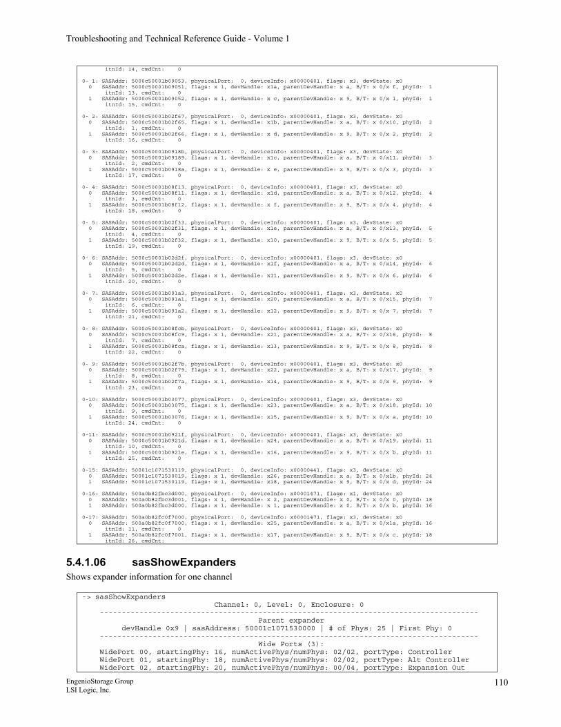
Troubleshooting and Technical Reference Guide - Volume 1
itnId: 14, cmdCnt: 0 0- 1: SASAddr: 5000c50001b09053, physicalPort: 0, deviceInfo: x00000401, flags: x3, devState: x0 0 SASAddr: 5000c50001b09051, flags: x 1, devHandle: x1a, parentDevHandle: x a, B/T: x 0/x f, phyId: 1 itnId: 13, cmdCnt: 0 1 SASAddr: 5000c50001b09052, flags: x 1, devHandle: x c, parentDevHandle: x 9, B/T: x 0/x 1, phyId: 1 itnId: 15, cmdCnt: 0 0- 2: SASAddr: 5000c50001b02f67, physicalPort: 0, deviceInfo: x00000401, flags: x3, devState: x0 0 SASAddr: 5000c50001b02f65, flags: x 1, devHandle: x1b, parentDevHandle: x a, B/T: x 0/x10, phyId: 2 itnId: 1, cmdCnt: 0 1 SASAddr: 5000c50001b02f66, flags: x 1, devHandle: x d, parentDevHandle: x 9, B/T: x 0/x 2, phyId: 2 itnId: 16, cmdCnt: 0 0- 3: SASAddr: 5000c50001b0918b, physicalPort: 0, deviceInfo: x00000401, flags: x3, devState: x0 0 SASAddr: 5000c50001b09189, flags: x 1, devHandle: x1c, parentDevHandle: x a, B/T: x 0/x11, phyId: 3 itnId: 2, cmdCnt: 0 1 SASAddr: 5000c50001b0918a, flags: x 1, devHandle: x e, parentDevHandle: x 9, B/T: x 0/x 3, phyId: 3 itnId: 17, cmdCnt: 0 0- 4: SASAddr: 5000c50001b08f13, physicalPort: 0, deviceInfo: x00000401, flags: x3, devState: x0 0 SASAddr: 5000c50001b08f11, flags: x 1, devHandle: x1d, parentDevHandle: x a, B/T: x 0/x12, phyId: 4 itnId: 3, cmdCnt: 0 1 SASAddr: 5000c50001b08f12, flags: x 1, devHandle: x f, parentDevHandle: x 9, B/T: x 0/x 4, phyId: 4 itnId: 18, cmdCnt: 0 0- 5: SASAddr: 5000c50001b02f33, physicalPort: 0, deviceInfo: x00000401, flags: x3, devState: x0 0 SASAddr: 5000c50001b02f31, flags: x 1, devHandle: x1e, parentDevHandle: x a, B/T: x 0/x13, phyId: 5 itnId: 4, cmdCnt: 0 1 SASAddr: 5000c50001b02f32, flags: x 1, devHandle: x10, parentDevHandle: x 9, B/T: x 0/x 5, phyId: 5 itnId: 19, cmdCnt: 0 0- 6: SASAddr: 5000c50001b02d2f, physicalPort: 0, deviceInfo: x00000401, flags: x3, devState: x0 0 SASAddr: 5000c50001b02d2d, flags: x 1, devHandle: x1f, parentDevHandle: x a, B/T: x 0/x14, phyId: 6 itnId: 5, cmdCnt: 0 1 SASAddr: 5000c50001b02d2e, flags: x 1, devHandle: x11, parentDevHandle: x 9, B/T: x 0/x 6, phyId: 6 itnId: 20, cmdCnt: 0 0- 7: SASAddr: 5000c50001b091a3, physicalPort: 0, deviceInfo: x00000401, flags: x3, devState: x0 0 SASAddr: 5000c50001b091a1, flags: x 1, devHandle: x20, parentDevHandle: x a, B/T: x 0/x15, phyId: 7 itnId: 6, cmdCnt: 0 1 SASAddr: 5000c50001b091a2, flags: x 1, devHandle: x12, parentDevHandle: x 9, B/T: x 0/x 7, phyId: 7 itnId: 21, cmdCnt: 0 0- 8: SASAddr: 5000c50001b08fcb, physicalPort: 0, deviceInfo: x00000401, flags: x3, devState: x0 0 SASAddr: 5000c50001b08fc9, flags: x 1, devHandle: x21, parentDevHandle: x a, B/T: x 0/x16, phyId: 8 itnId: 7, cmdCnt: 0 1 SASAddr: 5000c50001b08fca, flags: x 1, devHandle: x13, parentDevHandle: x 9, B/T: x 0/x 8, phyId: 8 itnId: 22, cmdCnt: 0 0- 9: SASAddr: 5000c50001b02f7b, physicalPort: 0, deviceInfo: x00000401, flags: x3, devState: x0 0 SASAddr: 5000c50001b02f79, flags: x 1, devHandle: x22, parentDevHandle: x a, B/T: x 0/x17, phyId: 9 itnId: 8, cmdCnt: 0 1 SASAddr: 5000c50001b02f7a, flags: x 1, devHandle: x14, parentDevHandle: x 9, B/T: x 0/x 9, phyId: 9 itnId: 23, cmdCnt: 0 0-10: SASAddr: 5000c50001b03077, physicalPort: 0, deviceInfo: x00000401, flags: x3, devState: x0 0 SASAddr: 5000c50001b03075, flags: x 1, devHandle: x23, parentDevHandle: x a, B/T: x 0/x18, phyId: 10 itnId: 9, cmdCnt: 0 1 SASAddr: 5000c50001b03076, flags: x 1, devHandle: x15, parentDevHandle: x 9, B/T: x 0/x a, phyId: 10 itnId: 24, cmdCnt: 0 0-11: SASAddr: 5000c50001b0921f, physicalPort: 0, deviceInfo: x00000401, flags: x3, devState: x0 0 SASAddr: 5000c50001b0921d, flags: x 1, devHandle: x24, parentDevHandle: x a, B/T: x 0/x19, phyId: 11 itnId: 10, cmdCnt: 0 1 SASAddr: 5000c50001b0921e, flags: x 1, devHandle: x16, parentDevHandle: x 9, B/T: x 0/x b, phyId: 11 itnId: 25, cmdCnt: 0 0-15: SASAddr: 50001c1071530119, physicalPort: 0, deviceInfo: x00000441, flags: x3, devState: x0 0 SASAddr: 50001c1071530019, flags: x 1, devHandle: x26, parentDevHandle: x a, B/T: x 0/x1b, phyId: 24 1 SASAddr: 50001c1071530119, flags: x 1, devHandle: x18, parentDevHandle: x 9, B/T: x 0/x d, phyId: 24 0-16: SASAddr: 500a0b82fbc3d000, physicalPort: 0, deviceInfo: x00001471, flags: x1, devState: x0 0 SASAddr: 500a0b82fbc3d001, flags: x 1, devHandle: x 2, parentDevHandle: x 0, B/T: x 0/x 0, phyId: 18 1 SASAddr: 500a0b82fbc3d000, flags: x 1, devHandle: x 1, parentDevHandle: x 0, B/T: x 0/x b, phyId: 16 0-17: SASAddr: 500a0b82fc0f7000, physicalPort: 0, deviceInfo: x00001471, flags: x3, devState: x0 0 SASAddr: 500a0b82fc0f7000, flags: x 1, devHandle: x25, parentDevHandle: x a, B/T: x 0/x1a, phyId: 16 itnId: 11, cmdCnt: 0 1 SASAddr: 500a0b82fc0f7001, flags: x 1, devHandle: x17, parentDevHandle: x 9, B/T: x 0/x c, phyId: 18 itnId: 26, cmdCnt:
5.4.1.06 sasShowExpanders Shows expander information for one channel
-> sasShowExpanders Channel: 0, Level: 0, Enclosure: 0 -------------------------------------------------------------------------------------- Parent expander devHandle 0x9 | sasAddress: 50001c1071530000 | # of Phys: 25 | First Phy: 0 -------------------------------------------------------------------------------------- Wide Ports (3): WidePort 00, startingPhy: 16, numActivePhys/numPhys: 02/02, portType: Controller WidePort 01, startingPhy: 18, numActivePhys/numPhys: 02/02, portType: Alt Controller WidePort 02, startingPhy: 20, numActivePhys/numPhys: 00/04, portType: Expansion Out
EngenioStorage Group LSI Logic, Inc.
110
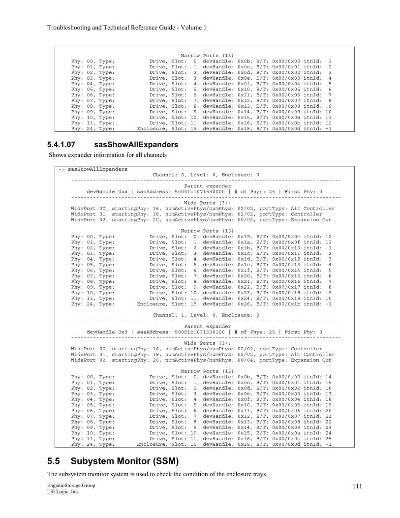
Troubleshooting and Technical Reference Guide - Volume 1
Narrow Ports (13): Phy: 00, Type: Drive, Slot: 0, devHandle: 0x0b, B/T: 0x00/0x00 itnId: 1 Phy: 01, Type: Drive, Slot: 1, devHandle: 0x0c, B/T: 0x00/0x01 itnId: 2 Phy: 02, Type: Drive, Slot: 2, devHandle: 0x0d, B/T: 0x00/0x02 itnId: 3 Phy: 03, Type: Drive, Slot: 3, devHandle: 0x0e, B/T: 0x00/0x03 itnId: 4 Phy: 04, Type: Drive, Slot: 4, devHandle: 0x0f, B/T: 0x00/0x04 itnId: 5 Phy: 05, Type: Drive, Slot: 5, devHandle: 0x10, B/T: 0x00/0x05 itnId: 6 Phy: 06, Type: Drive, Slot: 6, devHandle: 0x11, B/T: 0x00/0x06 itnId: 7 Phy: 07, Type: Drive, Slot: 7, devHandle: 0x12, B/T: 0x00/0x07 itnId: 8 Phy: 08, Type: Drive, Slot: 8, devHandle: 0x13, B/T: 0x00/0x08 itnId: 9 Phy: 09, Type: Drive, Slot: 9, devHandle: 0x14, B/T: 0x00/0x09 itnId: 10 Phy: 10, Type: Drive, Slot: 10, devHandle: 0x15, B/T: 0x00/0x0a itnId: 11 Phy: 11, Type: Drive, Slot: 11, devHandle: 0x16, B/T: 0x00/0x0b itnId: 12 Phy: 24, Type: Enclosure, Slot: 15, devHandle: 0x18, B/T: 0x00/0x0d itnId: -1
5.4.1.07 sasShowAllExpanders Shows expander information for all channels
-> sasShowAllExpanders Channel: 0, Level: 0, Enclosure: 0 -------------------------------------------------------------------------------------- Parent expander devHandle 0xa | sasAddress: 50001c1071530000 | # of Phys: 25 | First Phy: 0 -------------------------------------------------------------------------------------- Wide Ports (3): WidePort 00, startingPhy: 16, numActivePhys/numPhys: 02/02, portType: Alt Controller WidePort 01, startingPhy: 18, numActivePhys/numPhys: 02/02, portType: Controller WidePort 02, startingPhy: 20, numActivePhys/numPhys: 00/04, portType: Expansion Out Narrow Ports (13): Phy: 00, Type: Drive, Slot: 0, devHandle: 0x19, B/T: 0x00/0x0e itnId: 12 Phy: 01, Type: Drive, Slot: 1, devHandle: 0x1a, B/T: 0x00/0x0f itnId: 13 Phy: 02, Type: Drive, Slot: 2, devHandle: 0x1b, B/T: 0x00/0x10 itnId: 1 Phy: 03, Type: Drive, Slot: 3, devHandle: 0x1c, B/T: 0x00/0x11 itnId: 2 Phy: 04, Type: Drive, Slot: 4, devHandle: 0x1d, B/T: 0x00/0x12 itnId: 3 Phy: 05, Type: Drive, Slot: 5, devHandle: 0x1e, B/T: 0x00/0x13 itnId: 4 Phy: 06, Type: Drive, Slot: 6, devHandle: 0x1f, B/T: 0x00/0x14 itnId: 5 Phy: 07, Type: Drive, Slot: 7, devHandle: 0x20, B/T: 0x00/0x15 itnId: 6 Phy: 08, Type: Drive, Slot: 8, devHandle: 0x21, B/T: 0x00/0x16 itnId: 7 Phy: 09, Type: Drive, Slot: 9, devHandle: 0x22, B/T: 0x00/0x17 itnId: 8 Phy: 10, Type: Drive, Slot: 10, devHandle: 0x23, B/T: 0x00/0x18 itnId: 9 Phy: 11, Type: Drive, Slot: 11, devHandle: 0x24, B/T: 0x00/0x19 itnId: 10 Phy: 24, Type: Enclosure, Slot: 15, devHandle: 0x26, B/T: 0x00/0x1b itnId: -1 Channel: 1, Level: 0, Enclosure: 0 -------------------------------------------------------------------------------------- Parent expander devHandle 0x9 | sasAddress: 50001c1071530100 | # of Phys: 25 | First Phy: 0 -------------------------------------------------------------------------------------- Wide Ports (3): WidePort 00, startingPhy: 16, numActivePhys/numPhys: 02/02, portType: Controller WidePort 01, startingPhy: 18, numActivePhys/numPhys: 02/02, portType: Alt Controller WidePort 02, startingPhy: 20, numActivePhys/numPhys: 00/04, portType: Expansion Out Narrow Ports (13): Phy: 00, Type: Drive, Slot: 0, devHandle: 0x0b, B/T: 0x00/0x00 itnId: 14 Phy: 01, Type: Drive, Slot: 1, devHandle: 0x0c, B/T: 0x00/0x01 itnId: 15 Phy: 02, Type: Drive, Slot: 2, devHandle: 0x0d, B/T: 0x00/0x02 itnId: 16 Phy: 03, Type: Drive, Slot: 3, devHandle: 0x0e, B/T: 0x00/0x03 itnId: 17 Phy: 04, Type: Drive, Slot: 4, devHandle: 0x0f, B/T: 0x00/0x04 itnId: 18 Phy: 05, Type: Drive, Slot: 5, devHandle: 0x10, B/T: 0x00/0x05 itnId: 19 Phy: 06, Type: Drive, Slot: 6, devHandle: 0x11, B/T: 0x00/0x06 itnId: 20 Phy: 07, Type: Drive, Slot: 7, devHandle: 0x12, B/T: 0x00/0x07 itnId: 21 Phy: 08, Type: Drive, Slot: 8, devHandle: 0x13, B/T: 0x00/0x08 itnId: 22 Phy: 09, Type: Drive, Slot: 9, devHandle: 0x14, B/T: 0x00/0x09 itnId: 23 Phy: 10, Type: Drive, Slot: 10, devHandle: 0x15, B/T: 0x00/0x0a itnId: 24 Phy: 11, Type: Drive, Slot: 11, devHandle: 0x16, B/T: 0x00/0x0b itnId: 25 Phy: 24, Type: Enclosure, Slot: 15, devHandle: 0x18, B/T: 0x00/0x0d itnId: -1
5.5 Subystem Monitor (SSM) The subsystem monitor system is used to check the condition of the enclosure trays.
EngenioStorage Group LSI Logic, Inc.
111
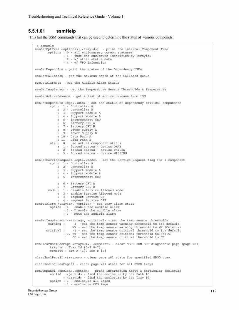
Troubleshooting and Technical Reference Guide - Volume 1
5.5.1.01 ssmHelp This list the SSM commands that can be used to determine the status of various componets.
-> ssmHelp ssmGetCptTree <options>[,<trayid>] - print the internal Component Tree options : 0 - all enclosures, common statuses : 1 - just one enclosure identified by <trayid> : 2 - w/ other status data : 4 - w/ VPD infomation ssmGetDependSts - print the status of the Dependency LEDs ssmGetCallbackQ - get the maximum depth of the Callback Queue ssmGetAlarmSts - get the Audible Alarm Status ssmGetTempSensor - get the Temperature Sensor Thresholds & Temperature ssmGetActiveDevnums - get a list of active devnums from ION ssmSetDependSts <cpt>,<sts> - set the status of Dependency critical components cpt : 1 - Controller A : 2 - Controller B : 3 - Support Module A : 4 - Support Module B : 5 - Interconnect CRU : 6 - Battery CRU A : 7 - Battery CRU B : 8 - Power Supply A : 9 - Power Supply B : 10 - Data Path A : 11 - Data Path B sts : 0 - use actual component status : 1 - forced status - device OKAY : 2 - forced status - device FAILED : 5 - forced status - device MISSING ssmSetServiceRequest <cpt>,<mode> - set the Service Request flag for a component cpt : 1 - Controller A : 2 - Controller B : 3 - Support Module A : 4 - Support Module B : 5 - Interconnect CRU : 6 - Battery CRU A : 7 - Battery CRU B mode : 1 - disable Service Allowed mode : 2 - enable Service Allowed mode : 3 - request Service ON : 4 - request Service OFF ssmSetAlarm <trayid>, <option> - set tray alarm state option : 1 - Enable the audible alarm : 2 - Disable the audible alarm : 3 - Mute the audible alarm ssmSetTempSensor <warning>, <critical> - set the temp sensor thresholds warning : -1 - set the temp sensor warning threshold to its default : WW - set the temp sensor warning threshold to WW (Celsius) critical : -1 - set the temp sensor critical threshold to its default : <= WW - set the temp sensor critical threshold to (WW+5) : CC - set the temp sensor critical thershold to CC ssmClearEnclSocPage <traynum>, <esmslot> - clear SBOD ESM SOC diagnostic page (page x81) traynum : Tray Id {0-7,0-7} esmslot : Esm A {1}, ESM B {2} clearEnclPage81 <traynum> - clear page x81 stats for specified SBOD tray clearEnclosuresPage81 - clear page x81 stats for all SBOD trays ssmDumpEncl <enclid>,<option> - print information about a particular enclosure enclid : <pathid> - find the enclosure by its Path Id : <trayid> - find the enclosure by its Tray Id option :-1 - enclosure all Pages : 1 - enclosure CFG Page
EngenioStorage Group LSI Logic, Inc.
112
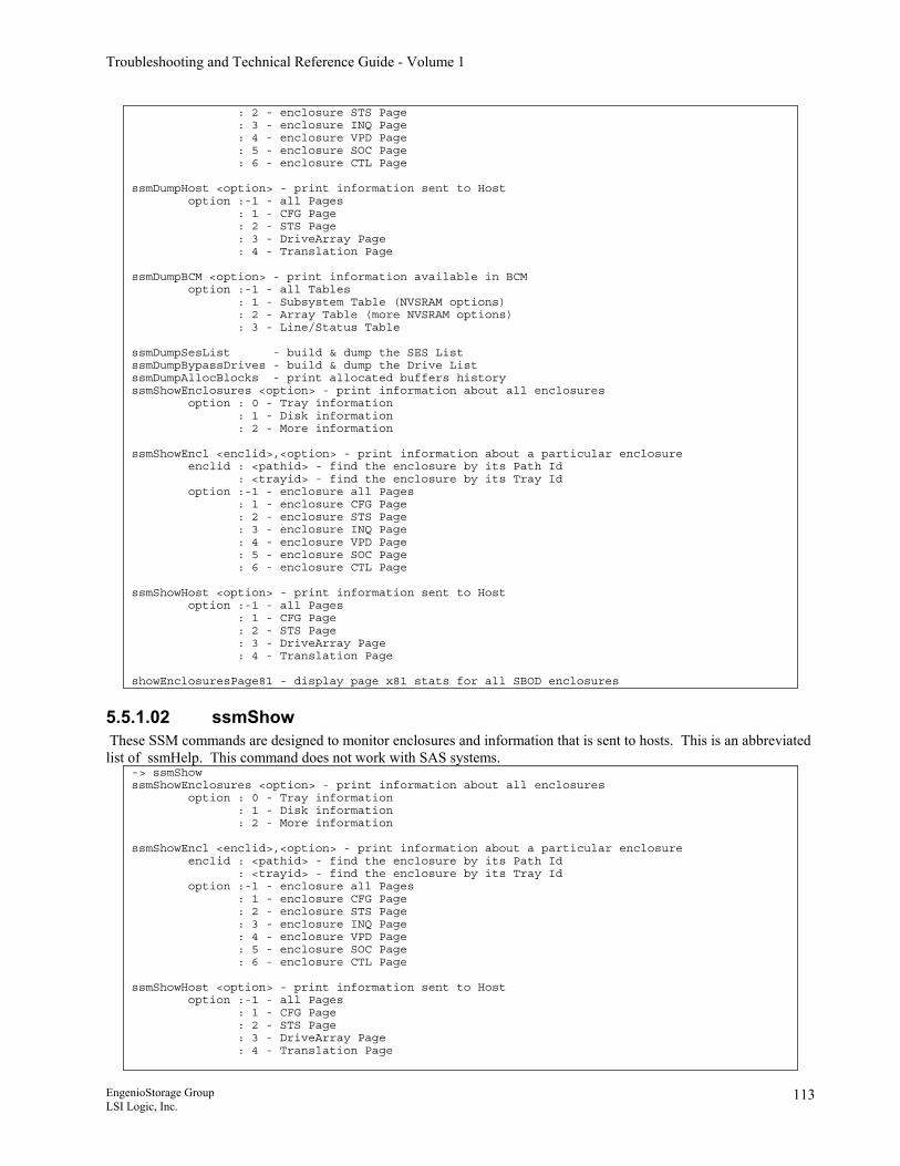
Troubleshooting and Technical Reference Guide - Volume 1
: 2 - enclosure STS Page : 3 - enclosure INQ Page : 4 - enclosure VPD Page : 5 - enclosure SOC Page : 6 - enclosure CTL Page ssmDumpHost <option> - print information sent to Host option :-1 - all Pages : 1 - CFG Page : 2 - STS Page : 3 - DriveArray Page : 4 - Translation Page ssmDumpBCM <option> - print information available in BCM option :-1 - all Tables : 1 - Subsystem Table (NVSRAM options) : 2 - Array Table (more NVSRAM options) : 3 - Line/Status Table ssmDumpSesList - build & dump the SES List ssmDumpBypassDrives - build & dump the Drive List ssmDumpAllocBlocks - print allocated buffers history ssmShowEnclosures <option> - print information about all enclosures option : 0 - Tray information : 1 - Disk information : 2 - More information ssmShowEncl <enclid>,<option> - print information about a particular enclosure enclid : <pathid> - find the enclosure by its Path Id : <trayid> - find the enclosure by its Tray Id option :-1 - enclosure all Pages : 1 - enclosure CFG Page : 2 - enclosure STS Page : 3 - enclosure INQ Page : 4 - enclosure VPD Page : 5 - enclosure SOC Page : 6 - enclosure CTL Page ssmShowHost <option> - print information sent to Host option :-1 - all Pages : 1 - CFG Page : 2 - STS Page : 3 - DriveArray Page : 4 - Translation Page showEnclosuresPage81 - display page x81 stats for all SBOD enclosures
5.5.1.02 ssmShow These SSM commands are designed to monitor enclosures and information that is sent to hosts. This is an abbreviated list of ssmHelp. This command does not work with SAS systems.
-> ssmShow ssmShowEnclosures <option> - print information about all enclosures option : 0 - Tray information : 1 - Disk information : 2 - More information ssmShowEncl <enclid>,<option> - print information about a particular enclosure enclid : <pathid> - find the enclosure by its Path Id : <trayid> - find the enclosure by its Tray Id option :-1 - enclosure all Pages : 1 - enclosure CFG Page : 2 - enclosure STS Page : 3 - enclosure INQ Page : 4 - enclosure VPD Page : 5 - enclosure SOC Page : 6 - enclosure CTL Page ssmShowHost <option> - print information sent to Host option :-1 - all Pages : 1 - CFG Page : 2 - STS Page : 3 - DriveArray Page : 4 - Translation Page
EngenioStorage Group LSI Logic, Inc.
113
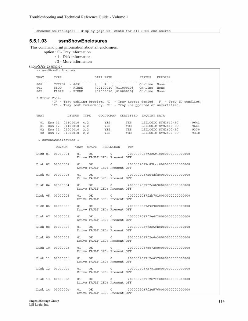
Troubleshooting and Technical Reference Guide - Volume 1
showEnclosuresPage81 - display page x81 stats for all SBOD enclosures
5.5.1.03 ssmShowEnclosures This command print information about all enclosures. option : 0 - Tray information : 1 - Disk information
: 2 - More information (non-SAS example)
-> ssmShowEnclosures TRAY TYPE DATA PATH STATUS ERRORS* -------- -------------------- ---------------------- -------- -------- 000 CNTRLR - 6091 [ A ] On-Line None 001 SBOD - FIBRE [02100010][01100010] On-Line None 002 FIBRE - FIBRE [02000010][01000010] On-Line None * Error Code: 'C' - Tray cabling problem. 'D' - Tray access denied. 'F' - Tray ID conflict. 'R' - Tray lost redundancy. 'U' - Tray unsupported or uncertified. TRAY DEVNUM TYPE GOODTOMAP CERTIFIED INQUIRY DATA 01 Esm 01 02100010 4,2 YES YES LSILOGIC SYM2610-FC 9641 01 Esm 02 01100010 4,2 YES YES LSILOGIC SYM2610-FC 9641 02 Esm 01 02000010 2,2 YES YES LSILOGIC SYM2600-FC 9330 02 Esm 02 01000010 2,2 YES YES LSILOGIC SYM2600-FC 9330 -> ssmShowEnclosures 1 DEVNUM TRAY STATE REDUNCHAN WWN Disk 01 00000001 01 OK 0 2000002037f2e6f10000000000000000 Drive FAULT LED: Present OFF Disk 02 00000002 01 OK 0 2000002037c87bcc0000000000000000 Drive FAULT LED: Present OFF Disk 03 00000003 01 OK 0 2000002037a54afa0000000000000000 Drive FAULT LED: Present OFF Disk 04 00000004 01 OK 0 2000002037f2e6b90000000000000000 Drive FAULT LED: Present OFF Disk 05 00000005 01 OK 0 2000002037f2b7810000000000000000 Drive FAULT LED: Present OFF Disk 06 00000006 01 OK 0 2000002037d9098c0000000000000000 Drive FAULT LED: Present OFF Disk 07 00000007 01 OK 0 2000002037f2e6f20000000000000000 Drive FAULT LED: Present OFF Disk 08 00000008 01 OK 0 2000002037f2e5fb0000000000000000 Drive FAULT LED: Present OFF Disk 09 00000009 01 OK 0 2000002037f2e6a30000000000000000 Drive FAULT LED: Present OFF Disk 10 0000000a 01 OK 0 2000002037ec728c0000000000000000 Drive FAULT LED: Present OFF Disk 11 0000000b 01 OK 0 2000002037f2e6370000000000000000 Drive FAULT LED: Present OFF Disk 12 0000000c 01 OK 0 2000002037a791aa0000000000000000 Drive FAULT LED: Present OFF Disk 13 0000000d 01 OK 0 2000002037f2b7ff0000000000000000 Drive FAULT LED: Present OFF Disk 14 0000000e 01 OK 0 2000002037f2e5760000000000000000 Drive FAULT LED: Present OFF
EngenioStorage Group LSI Logic, Inc.
114
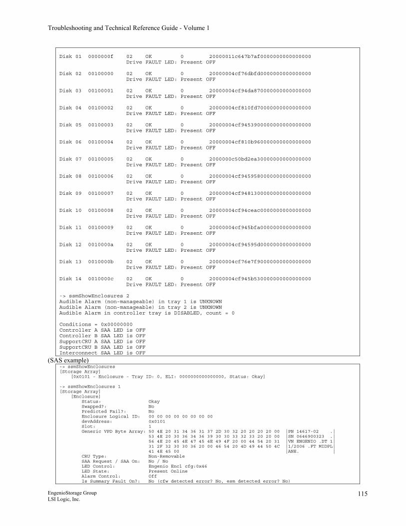
Troubleshooting and Technical Reference Guide - Volume 1
Disk 01 0000000f 02 OK 0 20000011c647b7af0000000000000000 Drive FAULT LED: Present OFF Disk 02 00100000 02 OK 0 20000004cf76dbfd0000000000000000 Drive FAULT LED: Present OFF Disk 03 00100001 02 OK 0 20000004cf94da870000000000000000 Drive FAULT LED: Present OFF Disk 04 00100002 02 OK 0 20000004cf810fd70000000000000000 Drive FAULT LED: Present OFF Disk 05 00100003 02 OK 0 20000004cf9453900000000000000000 Drive FAULT LED: Present OFF Disk 06 00100004 02 OK 0 20000004cf810b960000000000000000 Drive FAULT LED: Present OFF Disk 07 00100005 02 OK 0 2000000c50bd2ea30000000000000000 Drive FAULT LED: Present OFF Disk 08 00100006 02 OK 0 20000004cf9459580000000000000000 Drive FAULT LED: Present OFF Disk 09 00100007 02 OK 0 20000004cf9481300000000000000000 Drive FAULT LED: Present OFF Disk 10 00100008 02 OK 0 20000004cf94ceac0000000000000000 Drive FAULT LED: Present OFF Disk 11 00100009 02 OK 0 20000004cf945bfa0000000000000000 Drive FAULT LED: Present OFF Disk 12 0010000a 02 OK 0 20000004cf94595d0000000000000000 Drive FAULT LED: Present OFF Disk 13 0010000b 02 OK 0 20000004cf76e7f90000000000000000 Drive FAULT LED: Present OFF Disk 14 0010000c 02 OK 0 20000004cf945b530000000000000000 Drive FAULT LED: Present OFF -> ssmShowEnclosures 2 Audible Alarm (non-manageable) in tray 1 is UNKNOWN Audible Alarm (non-manageable) in tray 2 is UNKNOWN Audible Alarm in controller tray is DISABLED, count = 0 Conditions = 0x00000000 Controller A SAA LED is OFF Controller B SAA LED is OFF SupportCRU A SAA LED is OFF SupportCRU B SAA LED is OFF Interconnect SAA LED is OFF
(SAS example) -> ssmShowEnclosures [Storage Array] [0x0101 - Enclosure - Tray ID: 0, ELI: 0000000000000000, Status: Okay] -> ssmShowEnclosures 1 [Storage Array] [Enclosure] Status: Okay Swapped?: No Predicted Fail?: No Enclosure Logical ID: 00 00 00 00 00 00 00 00 devAddress: 0x0101 Slot: 1 Generic VPD Byte Array: 50 4E 20 31 34 36 31 37 2D 30 32 20 20 20 20 00 |PN 14617-02 .| 53 4E 20 30 36 34 36 39 30 30 33 32 33 20 20 00 |SN 0646900323 .| 56 4E 20 45 4E 47 45 4E 49 4F 20 00 44 54 20 31 |VN ENGENIO .DT 1| 31 2F 32 30 30 36 20 00 46 54 20 4D 49 44 50 4C |1/2006 .FT MIDPL| 41 4E 45 00 |ANE. | CRU Type: Non-Removable SAA Request / SAA On: No / No LED Control: Engenio Encl cfg:0x46 LED State: Present Online Alarm Control: Off Is Summary Fault On?: No (cfw detected error? No, esm detected error? No)
EngenioStorage Group LSI Logic, Inc.
115
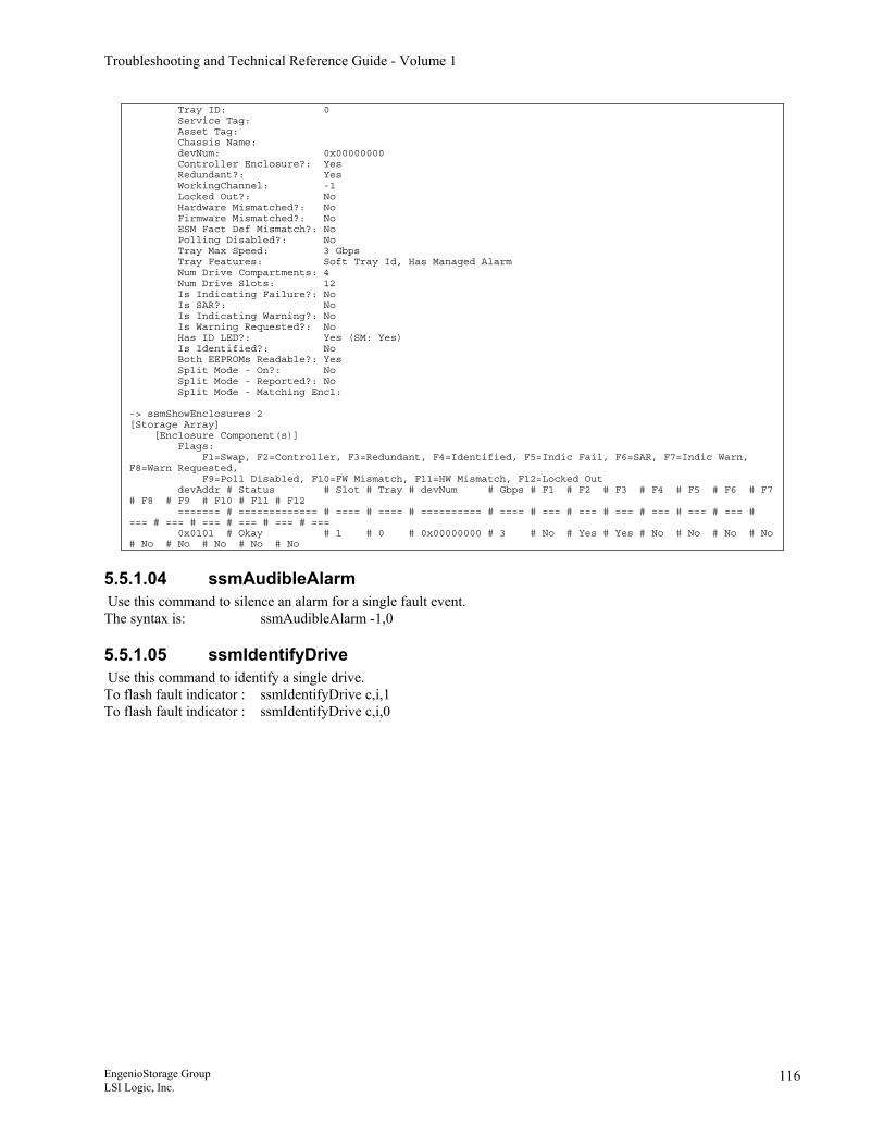
Troubleshooting and Technical Reference Guide - Volume 1
Tray ID: 0 Service Tag: Asset Tag: Chassis Name: devNum: 0x00000000 Controller Enclosure?: Yes Redundant?: Yes WorkingChannel: -1 Locked Out?: No Hardware Mismatched?: No Firmware Mismatched?: No ESM Fact Def Mismatch?: No Polling Disabled?: No Tray Max Speed: 3 Gbps Tray Features: Soft Tray Id, Has Managed Alarm Num Drive Compartments: 4 Num Drive Slots: 12 Is Indicating Failure?: No Is SAR?: No Is Indicating Warning?: No Is Warning Requested?: No Has ID LED?: Yes (SM: Yes) Is Identified?: No Both EEPROMs Readable?: Yes Split Mode - On?: No Split Mode - Reported?: No Split Mode - Matching Encl: -> ssmShowEnclosures 2 [Storage Array] [Enclosure Component(s)] Flags: F1=Swap, F2=Controller, F3=Redundant, F4=Identified, F5=Indic Fail, F6=SAR, F7=Indic Warn, F8=Warn Requested, F9=Poll Disabled, F10=FW Mismatch, F11=HW Mismatch, F12=Locked Out devAddr # Status # Slot # Tray # devNum # Gbps # F1 # F2 # F3 # F4 # F5 # F6 # F7 # F8 # F9 # F10 # F11 # F12 ======= # ============= # ==== # ==== # ========== # ==== # === # === # === # === # === # === # === # === # === # === # === # === 0x0101 # Okay # 1 # 0 # 0x00000000 # 3 # No # Yes # Yes # No # No # No # No # No # No # No # No # No
5.5.1.04 ssmAudibleAlarm Use this command to silence an alarm for a single fault event. The syntax is: ssmAudibleAlarm -1,0
5.5.1.05 ssmIdentifyDrive Use this command to identify a single drive. To flash fault indicator : ssmIdentifyDrive c,i,1 To flash fault indicator : ssmIdentifyDrive c,i,0
EngenioStorage Group LSI Logic, Inc.
116
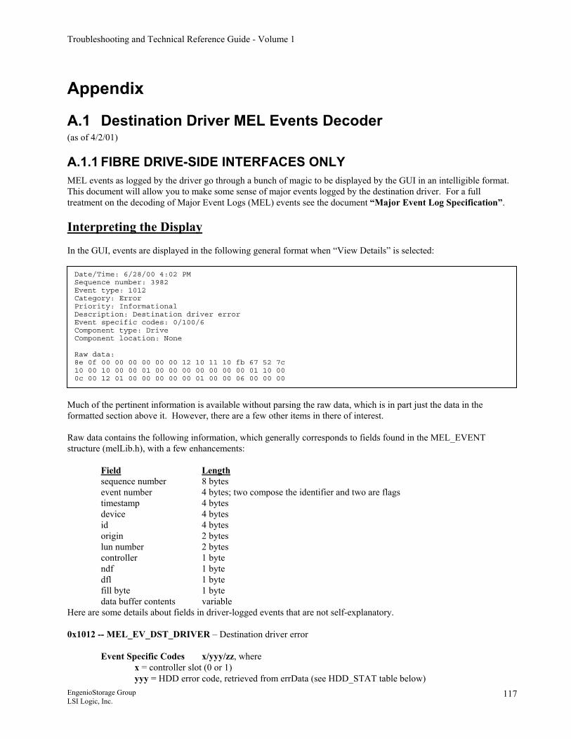
Troubleshooting and Technical Reference Guide - Volume 1
Appendix
A.1 Destination Driver MEL Events Decoder (as of 4/2/01)
A.1.1 FIBRE DRIVE-SIDE INTERFACES ONLY MEL events as logged by the driver go through a bunch of magic to be displayed by the GUI in an intelligible format. This document will allow you to make some sense of major events logged by the destination driver. For a full treatment on the decoding of Major Event Logs (MEL) events see the document “Major Event Log Specification”. Interpreting the Display In the GUI, events are displayed in the following general format when “View Details” is selected:
Date/Time: 6/28/00 4:02 PM Sequence number: 3982 Event type: 1012 Category: Error Priority: Informational Description: Destination driver error Event specific codes: 0/100/6 Component type: Drive Component location: None Raw data: 8e 0f 00 00 00 00 00 00 12 10 11 10 fb 67 52 7c 10 00 10 00 00 01 00 00 00 00 00 00 00 01 10 00 0c 00 12 01 00 00 00 00 00 01 00 00 06 00 00 00
Much of the pertinent information is available without parsing the raw data, which is in part just the data in the formatted section above it. However, there are a few other items in there of interest. Raw data contains the following information, which generally corresponds to fields found in the MEL_EVENT structure (melLib.h), with a few enhancements: Field Length sequence number 8 bytes event number 4 bytes; two compose the identifier and two are flags timestamp 4 bytes device 4 bytes id 4 bytes origin 2 bytes lun number 2 bytes controller 1 byte ndf 1 byte dfl 1 byte fill byte 1 byte data buffer contents variable Here are some details about fields in driver-logged events that are not self-explanatory. 0x1012 -- MEL_EV_DST_DRIVER – Destination driver error
Event Specific Codes x/yyy/zz, where
x = controller slot (0 or 1) yyy = HDD error code, retrieved from errData (see HDD_STAT table below)
EngenioStorage Group LSI Logic, Inc.
117
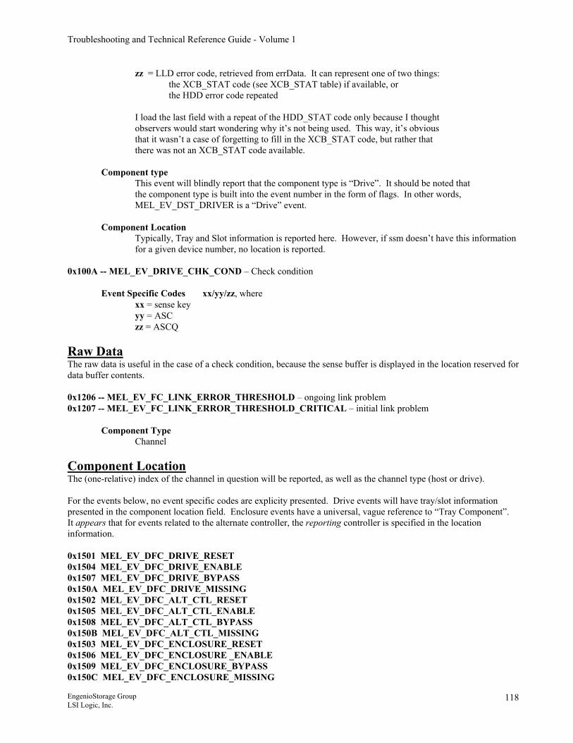
Troubleshooting and Technical Reference Guide - Volume 1
zz = LLD error code, retrieved from errData. It can represent one of two things: the XCB_STAT code (see XCB_STAT table) if available, or the HDD error code repeated
I load the last field with a repeat of the HDD_STAT code only because I thought observers would start wondering why it’s not being used. This way, it’s obvious that it wasn’t a case of forgetting to fill in the XCB_STAT code, but rather that there was not an XCB_STAT code available. Component type This event will blindly report that the component type is “Drive”. It should be noted that the component type is built into the event number in the form of flags. In other words, MEL_EV_DST_DRIVER is a “Drive” event. Component Location
Typically, Tray and Slot information is reported here. However, if ssm doesn’t have this information for a given device number, no location is reported.
0x100A -- MEL_EV_DRIVE_CHK_COND – Check condition
Event Specific Codes xx/yy/zz, where xx = sense key yy = ASC
zz = ASCQ
Raw Data The raw data is useful in the case of a check condition, because the sense buffer is displayed in the location reserved for data buffer contents. 0x1206 -- MEL_EV_FC_LINK_ERROR_THRESHOLD – ongoing link problem 0x1207 -- MEL_EV_FC_LINK_ERROR_THRESHOLD_CRITICAL – initial link problem Component Type
Channel
Component Location The (one-relative) index of the channel in question will be reported, as well as the channel type (host or drive). For the events below, no event specific codes are explicity presented. Drive events will have tray/slot information presented in the component location field. Enclosure events have a universal, vague reference to “Tray Component”. It appears that for events related to the alternate controller, the reporting controller is specified in the location information. 0x1501 MEL_EV_DFC_DRIVE_RESET 0x1504 MEL_EV_DFC_DRIVE_ENABLE 0x1507 MEL_EV_DFC_DRIVE_BYPASS 0x150A MEL_EV_DFC_DRIVE_MISSING 0x1502 MEL_EV_DFC_ALT_CTL_RESET 0x1505 MEL_EV_DFC_ALT_CTL_ENABLE 0x1508 MEL_EV_DFC_ALT_CTL_BYPASS 0x150B MEL_EV_DFC_ALT_CTL_MISSING 0x1503 MEL_EV_DFC_ENCLOSURE_RESET 0x1506 MEL_EV_DFC_ENCLOSURE _ENABLE 0x1509 MEL_EV_DFC_ENCLOSURE_BYPASS 0x150C MEL_EV_DFC_ENCLOSURE_MISSING
EngenioStorage Group LSI Logic, Inc.
118
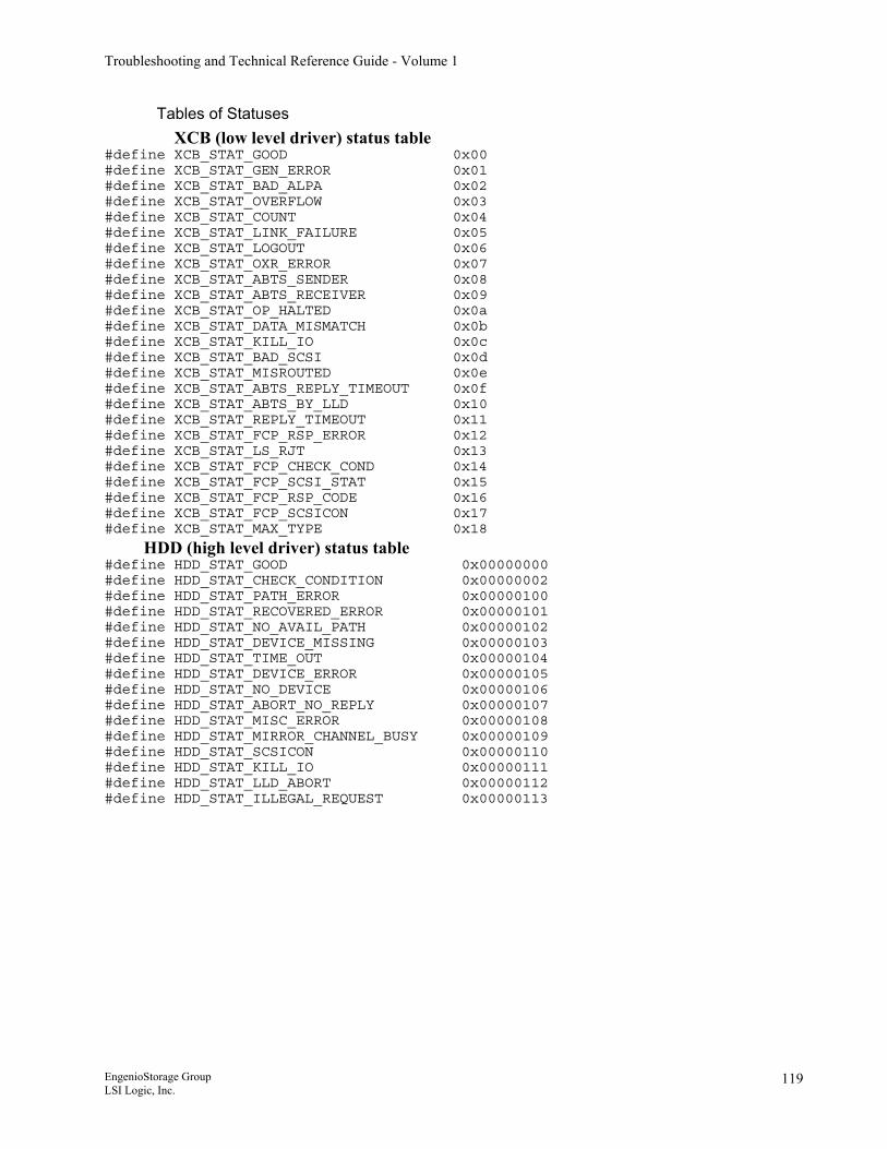
Troubleshooting and Technical Reference Guide - Volume 1
Tables of Statuses XCB (low level driver) status table
#define XCB_STAT_GOOD 0x00 #define XCB_STAT_GEN_ERROR 0x01 #define XCB_STAT_BAD_ALPA 0x02 #define XCB_STAT_OVERFLOW 0x03 #define XCB_STAT_COUNT 0x04 #define XCB_STAT_LINK_FAILURE 0x05 #define XCB_STAT_LOGOUT 0x06 #define XCB_STAT_OXR_ERROR 0x07 #define XCB_STAT_ABTS_SENDER 0x08 #define XCB_STAT_ABTS_RECEIVER 0x09 #define XCB_STAT_OP_HALTED 0x0a #define XCB_STAT_DATA_MISMATCH 0x0b #define XCB_STAT_KILL_IO 0x0c #define XCB_STAT_BAD_SCSI 0x0d #define XCB_STAT_MISROUTED 0x0e #define XCB_STAT_ABTS_REPLY_TIMEOUT 0x0f #define XCB_STAT_ABTS_BY_LLD 0x10 #define XCB_STAT_REPLY_TIMEOUT 0x11 #define XCB_STAT_FCP_RSP_ERROR 0x12 #define XCB_STAT_LS_RJT 0x13 #define XCB_STAT_FCP_CHECK_COND 0x14 #define XCB_STAT_FCP_SCSI_STAT 0x15 #define XCB_STAT_FCP_RSP_CODE 0x16 #define XCB_STAT_FCP_SCSICON 0x17 #define XCB_STAT_MAX_TYPE 0x18
HDD (high level driver) status table #define HDD_STAT_GOOD 0x00000000 #define HDD_STAT_CHECK_CONDITION 0x00000002 #define HDD_STAT_PATH_ERROR 0x00000100 #define HDD_STAT_RECOVERED_ERROR 0x00000101 #define HDD_STAT_NO_AVAIL_PATH 0x00000102 #define HDD_STAT_DEVICE_MISSING 0x00000103 #define HDD_STAT_TIME_OUT 0x00000104 #define HDD_STAT_DEVICE_ERROR 0x00000105 #define HDD_STAT_NO_DEVICE 0x00000106 #define HDD_STAT_ABORT_NO_REPLY 0x00000107 #define HDD_STAT_MISC_ERROR 0x00000108 #define HDD_STAT_MIRROR_CHANNEL_BUSY 0x00000109 #define HDD_STAT_SCSICON 0x00000110 #define HDD_STAT_KILL_IO 0x00000111 #define HDD_STAT_LLD_ABORT 0x00000112 #define HDD_STAT_ILLEGAL_REQUEST 0x00000113
EngenioStorage Group LSI Logic, Inc.
119
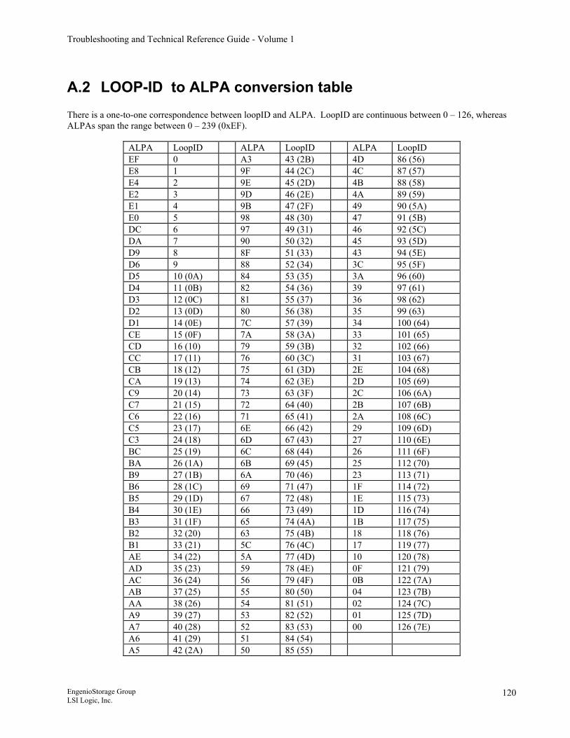
Troubleshooting and Technical Reference Guide - Volume 1
A.2 LOOP-ID to ALPA conversion table There is a one-to-one correspondence between loopID and ALPA. LoopID are continuous between 0 – 126, whereas ALPAs span the range between 0 – 239 (0xEF).
ALPA LoopID ALPA LoopID ALPA LoopID EF 0 A3 43 (2B) 4D 86 (56) E8 1 9F 44 (2C) 4C 87 (57) E4 2 9E 45 (2D) 4B 88 (58) E2 3 9D 46 (2E) 4A 89 (59) E1 4 9B 47 (2F) 49 90 (5A) E0 5 98 48 (30) 47 91 (5B) DC 6 97 49 (31) 46 92 (5C) DA 7 90 50 (32) 45 93 (5D) D9 8 8F 51 (33) 43 94 (5E) D6 9 88 52 (34) 3C 95 (5F) D5 10 (0A) 84 53 (35) 3A 96 (60) D4 11 (0B) 82 54 (36) 39 97 (61) D3 12 (0C) 81 55 (37) 36 98 (62) D2 13 (0D) 80 56 (38) 35 99 (63) D1 14 (0E) 7C 57 (39) 34 100 (64) CE 15 (0F) 7A 58 (3A) 33 101 (65) CD 16 (10) 79 59 (3B) 32 102 (66) CC 17 (11) 76 60 (3C) 31 103 (67) CB 18 (12) 75 61 (3D) 2E 104 (68) CA 19 (13) 74 62 (3E) 2D 105 (69) C9 20 (14) 73 63 (3F) 2C 106 (6A) C7 21 (15) 72 64 (40) 2B 107 (6B) C6 22 (16) 71 65 (41) 2A 108 (6C) C5 23 (17) 6E 66 (42) 29 109 (6D) C3 24 (18) 6D 67 (43) 27 110 (6E) BC 25 (19) 6C 68 (44) 26 111 (6F) BA 26 (1A) 6B 69 (45) 25 112 (70) B9 27 (1B) 6A 70 (46) 23 113 (71) B6 28 (1C) 69 71 (47) 1F 114 (72) B5 29 (1D) 67 72 (48) 1E 115 (73) B4 30 (1E) 66 73 (49) 1D 116 (74) B3 31 (1F) 65 74 (4A) 1B 117 (75) B2 32 (20) 63 75 (4B) 18 118 (76) B1 33 (21) 5C 76 (4C) 17 119 (77) AE 34 (22) 5A 77 (4D) 10 120 (78) AD 35 (23) 59 78 (4E) 0F 121 (79) AC 36 (24) 56 79 (4F) 0B 122 (7A) AB 37 (25) 55 80 (50) 04 123 (7B) AA 38 (26) 54 81 (51) 02 124 (7C) A9 39 (27) 53 82 (52) 01 125 (7D) A7 40 (28) 52 83 (53) 00 126 (7E) A6 41 (29) 51 84 (54) A5 42 (2A) 50 85 (55)
EngenioStorage Group LSI Logic, Inc.
120
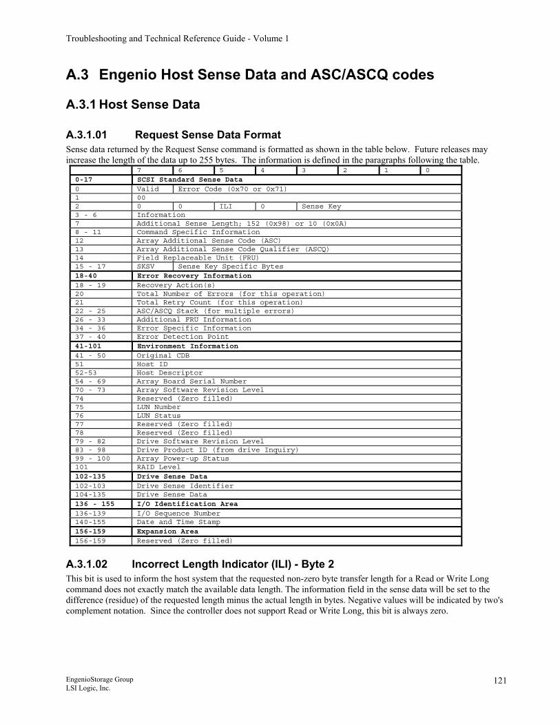
Troubleshooting and Technical Reference Guide - Volume 1
A.3 Engenio Host Sense Data and ASC/ASCQ codes
A.3.1 Host Sense Data
A.3.1.01 Request Sense Data Format Sense data returned by the Request Sense command is formatted as shown in the table below. Future releases may increase the length of the data up to 255 bytes. The information is defined in the paragraphs following the table.
7 6 5 4 3 2 1 0 0-17 SCSI Standard Sense Data 0 Valid Error Code (0x70 or 0x71) 1 00 2 0 0 ILI 0 Sense Key 3 - 6 Information 7 Additional Sense Length; 152 (0x98) or 10 (0x0A) 8 - 11 Command Specific Information 12 Array Additional Sense Code (ASC) 13 Array Additional Sense Code Qualifier (ASCQ) 14 Field Replaceable Unit (FRU) 15 - 17 SKSV Sense Key Specific Bytes 18-40 Error Recovery Information 18 - 19 Recovery Action(s) 20 Total Number of Errors (for this operation) 21 Total Retry Count (for this operation) 22 - 25 ASC/ASCQ Stack (for multiple errors) 26 - 33 Additional FRU Information 34 - 36 Error Specific Information 37 - 40 Error Detection Point 41-101 Environment Information 41 - 50 Original CDB 51 Host ID 52-53 Host Descriptor 54 - 69 Array Board Serial Number 70 - 73 Array Software Revision Level 74 Reserved (Zero filled) 75 LUN Number 76 LUN Status 77 Reserved (Zero filled) 78 Reserved (Zero filled) 79 - 82 Drive Software Revision Level 83 - 98 Drive Product ID (from drive Inquiry) 99 - 100 Array Power-up Status 101 RAID Level 102-135 Drive Sense Data 102-103 Drive Sense Identifier 104-135 Drive Sense Data 136 - 155 I/O Identification Area 136-139 I/O Sequence Number 140-155 Date and Time Stamp 156-159 Expansion Area 156-159 Reserved (Zero filled)
A.3.1.02 Incorrect Length Indicator (ILI) - Byte 2 This bit is used to inform the host system that the requested non-zero byte transfer length for a Read or Write Long command does not exactly match the available data length. The information field in the sense data will be set to the difference (residue) of the requested length minus the actual length in bytes. Negative values will be indicated by two's complement notation. Since the controller does not support Read or Write Long, this bit is always zero.
EngenioStorage Group LSI Logic, Inc.
121
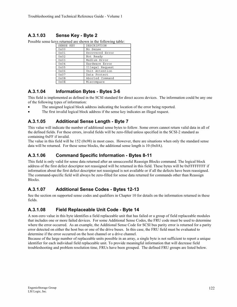
Troubleshooting and Technical Reference Guide - Volume 1
A.3.1.03 Sense Key - Byte 2 Possible sense keys returned are shown in the following table:
SENSE KEY DESCRIPTION 0x00 No Sense 0x01 Recovered Error 0x02 Not Ready 0x03 Medium Error 0x04 Hardware Error 0x05 Illegal Request 0x06 Unit Attention 0x07 Data Protect 0x0B Aborted Command 0x0E Miscompare
A.3.1.04 Information Bytes - Bytes 3-6 This field is implemented as defined in the SCSI standard for direct access devices. The information could be any one of the following types of information: • The unsigned logical block address indicating the location of the error being reported. • The first invalid logical block address if the sense key indicates an illegal request.
A.3.1.05 Additional Sense Length - Byte 7 This value will indicate the number of additional sense bytes to follow. Some errors cannot return valid data in all of the defined fields. For these errors, invalid fields will be zero-filled unless specified in the SCSI-2 standard as containing 0xFF if invalid. The value in this field will be 152 (0x98) in most cases. However, there are situations when only the standard sense data will be returned. For these sense blocks, the additional sense length is 10 (0x0A).
A.3.1.06 Command Specific Information - Bytes 8-11 This field is only valid for sense data returned after an unsuccessful Reassign Blocks command. The logical block address of the first defect descriptor not reassigned will be returned in this field. These bytes will be 0xFFFFFFFF if information about the first defect descriptor not reassigned is not available or if all the defects have been reassigned. The command-specific field will always be zero-filled for sense data returned for commands other than Reassign Blocks.
A.3.1.07 Additional Sense Codes - Bytes 12-13 See the section on supported sense codes and qualifiers in Chapter 10 for details on the information returned in these fields.
A.3.1.08 Field Replaceable Unit Code - Byte 14 A non-zero value in this byte identifies a field replaceable unit that has failed or a group of field replaceable modules that includes one or more failed devices. For some Additional Sense Codes, the FRU code must be used to determine where the error occurred. As an example, the Additional Sense Code for SCSI bus parity error is returned for a parity error detected on either the host bus or one of the drive buses. In this case, the FRU field must be evaluated to determine if the error occurred on the host channel or a drive channel. Because of the large number of replaceable units possible in an array, a single byte is not sufficient to report a unique identifier for each individual field replaceable unit. To provide meaningful information that will decrease field troubleshooting and problem resolution time, FRUs have been grouped. The defined FRU groups are listed below.
EngenioStorage Group LSI Logic, Inc.
122
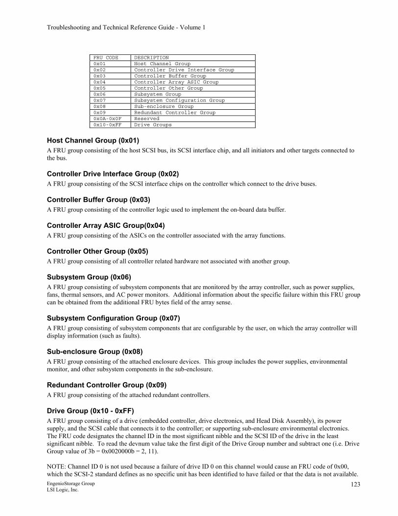
Troubleshooting and Technical Reference Guide - Volume 1
FRU CODE DESCRIPTION 0x01 Host Channel Group 0x02 Controller Drive Interface Group 0x03 Controller Buffer Group 0x04 Controller Array ASIC Group 0x05 Controller Other Group 0x06 Subsystem Group 0x07 Subsystem Configuration Group 0x08 Sub-enclosure Group 0x09 Redundant Controller Group 0x0A-0x0F Reserved 0x10-0xFF Drive Groups
Host Channel Group (0x01) A FRU group consisting of the host SCSI bus, its SCSI interface chip, and all initiators and other targets connected to the bus.
Controller Drive Interface Group (0x02) A FRU group consisting of the SCSI interface chips on the controller which connect to the drive buses.
Controller Buffer Group (0x03) A FRU group consisting of the controller logic used to implement the on-board data buffer.
Controller Array ASIC Group(0x04) A FRU group consisting of the ASICs on the controller associated with the array functions.
Controller Other Group (0x05) A FRU group consisting of all controller related hardware not associated with another group.
Subsystem Group (0x06) A FRU group consisting of subsystem components that are monitored by the array controller, such as power supplies, fans, thermal sensors, and AC power monitors. Additional information about the specific failure within this FRU group can be obtained from the additional FRU bytes field of the array sense.
Subsystem Configuration Group (0x07) A FRU group consisting of subsystem components that are configurable by the user, on which the array controller will display information (such as faults).
Sub-enclosure Group (0x08) A FRU group consisting of the attached enclosure devices. This group includes the power supplies, environmental monitor, and other subsystem components in the sub-enclosure.
Redundant Controller Group (0x09) A FRU group consisting of the attached redundant controllers.
Drive Group (0x10 - 0xFF) A FRU group consisting of a drive (embedded controller, drive electronics, and Head Disk Assembly), its power supply, and the SCSI cable that connects it to the controller; or supporting sub-enclosure environmental electronics. The FRU code designates the channel ID in the most significant nibble and the SCSI ID of the drive in the least significant nibble. To read the devnum value take the first digit of the Drive Group number and subtract one (i.e. Drive Group value of 3b = 0x0020000b = 2, 11). NOTE: Channel ID 0 is not used because a failure of drive ID 0 on this channel would cause an FRU code of 0x00, which the SCSI-2 standard defines as no specific unit has been identified to have failed or that the data is not available. EngenioStorage Group LSI Logic, Inc.
123
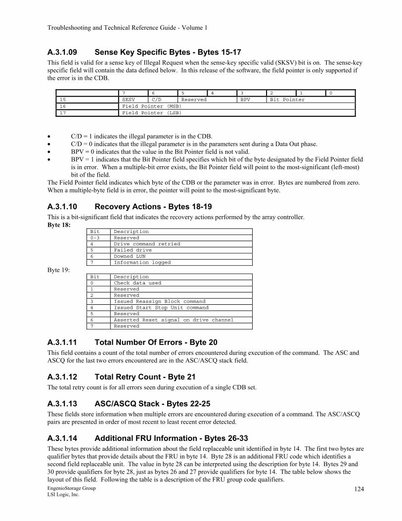
Troubleshooting and Technical Reference Guide - Volume 1
A.3.1.09 Sense Key Specific Bytes - Bytes 15-17 This field is valid for a sense key of Illegal Request when the sense-key specific valid (SKSV) bit is on. The sense-key specific field will contain the data defined below. In this release of the software, the field pointer is only supported if the error is in the CDB.
7 6 5 4 3 2 1 0 15 SKSV C/D Reserved BPV Bit Pointer 16 Field Pointer (MSB) 17 Field Pointer (LSB)
• C/D = 1 indicates the illegal parameter is in the CDB. • C/D = 0 indicates that the illegal parameter is in the parameters sent during a Data Out phase. • BPV = 0 indicates that the value in the Bit Pointer field is not valid. • BPV = 1 indicates that the Bit Pointer field specifies which bit of the byte designated by the Field Pointer field
is in error. When a multiple-bit error exists, the Bit Pointer field will point to the most-significant (left-most) bit of the field.
The Field Pointer field indicates which byte of the CDB or the parameter was in error. Bytes are numbered from zero. When a multiple-byte field is in error, the pointer will point to the most-significant byte.
A.3.1.10 Recovery Actions - Bytes 18-19 This is a bit-significant field that indicates the recovery actions performed by the array controller. Byte 18:
Bit Description 0-3 Reserved 4 Drive command retried 5 Failed drive 6 Downed LUN 7 Information logged
Byte 19: Bit Description 0 Check data used 1 Reserved 2 Reserved 3 Issued Reassign Block command 4 Issued Start Stop Unit command 5 Reserved 6 Asserted Reset signal on drive channel 7 Reserved
A.3.1.11 Total Number Of Errors - Byte 20 This field contains a count of the total number of errors encountered during execution of the command. The ASC and ASCQ for the last two errors encountered are in the ASC/ASCQ stack field.
A.3.1.12 Total Retry Count - Byte 21 The total retry count is for all errors seen during execution of a single CDB set.
A.3.1.13 ASC/ASCQ Stack - Bytes 22-25 These fields store information when multiple errors are encountered during execution of a command. The ASC/ASCQ pairs are presented in order of most recent to least recent error detected.
A.3.1.14 Additional FRU Information - Bytes 26-33 These bytes provide additional information about the field replaceable unit identified in byte 14. The first two bytes are qualifier bytes that provide details about the FRU in byte 14. Byte 28 is an additional FRU code which identifies a second field replaceable unit. The value in byte 28 can be interpreted using the description for byte 14. Bytes 29 and 30 provide qualifiers for byte 28, just as bytes 26 and 27 provide qualifiers for byte 14. The table below shows the layout of this field. Following the table is a description of the FRU group code qualifiers. EngenioStorage Group LSI Logic, Inc.
124
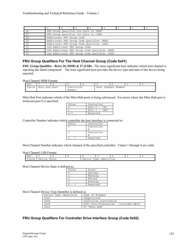
Troubleshooting and Technical Reference Guide - Volume 1
7 6 5 4 3 2 1 0 26 FRU Group Qualifier for byte 14 (MSB) 27 FRU Group Qualifier for byte 14 (LSB) 28 Additional FRU Group Code 29 Additional FRU Group Code Qualifier (MSB) 30 Additional FRU Group Code Qualifier (LSB) 31 2nd Additional FRU Group Code 32 2nd Additional FRU Group Code Qualifier (MSB) 33 2nd Additional FRU Group Code Qualifier (LSB)
FRU Group Qualifiers For The Host Channel Group (Code 0x01) FRU Group Qualifier - Bytes 26 (MSB) & 27 (LSB) - The most significant byte indicates which host channel is reporting the failed component. The least significant byte provides the device type and state of the device being reported. Host Channel MSB Format:
Bit 7 6 5 4 3 2 1 0 Field Mini-Hub Port Controller
Number Host Channel Number
Mini-Hub Port indicates which of the Mini-Hub ports is being referenced. For errors where the Mini-Hub port is irrelevant port 0 is specified.
Value Controller 0 Port 0 – ‘IN’ 1 Port 1 – ‘OUT’ 2-3 Reserved
Controller Number indicates which controller the host interface is connected to.
Value Controller 0 Controller
A 1 Controller
B 2 - 7 Reserved
Host Channel Number indicates which channel of the specified controller. Values 1 through 4 are valid. Host Channel LSB Format:
Bit 7 6 5 4 3 2 1 0 Field Device State Device Type Identifier
Host Channel Device State is defined as:
Value State 0 Optimal 1 Warning 2 Failed 3 Missing 4 - 7 Reserved
Host Channel Device Type Identifier is defined as:
Device Type Identifier Type of Element 0x00 Unspecified 0x08 Controller electronics 0x0F SCSI Port/Transceiver (includes GBIC) 0x16 FC “Mini-Hub”
FRU Group Qualifiers For Controller Drive Interface Group (Code 0x02)
EngenioStorage Group LSI Logic, Inc.
125
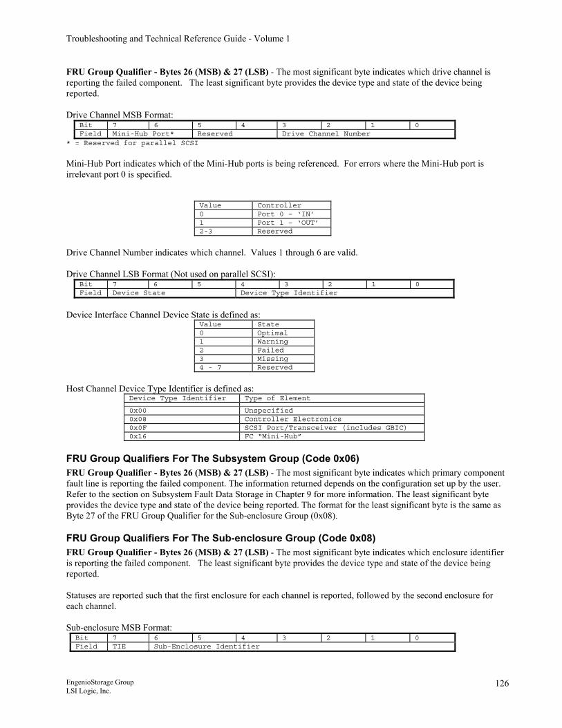
Troubleshooting and Technical Reference Guide - Volume 1
FRU Group Qualifier - Bytes 26 (MSB) & 27 (LSB) - The most significant byte indicates which drive channel is reporting the failed component. The least significant byte provides the device type and state of the device being reported. Drive Channel MSB Format:
Bit 7 6 5 4 3 2 1 0 Field Mini-Hub Port* Reserved Drive Channel Number
* = Reserved for parallel SCSI
Mini-Hub Port indicates which of the Mini-Hub ports is being referenced. For errors where the Mini-Hub port is irrelevant port 0 is specified.
Value Controller 0 Port 0 – ‘IN’ 1 Port 1 – ‘OUT’ 2-3 Reserved
Drive Channel Number indicates which channel. Values 1 through 6 are valid. Drive Channel LSB Format (Not used on parallel SCSI):
Bit 7 6 5 4 3 2 1 0 Field Device State Device Type Identifier
Device Interface Channel Device State is defined as:
Value State 0 Optimal 1 Warning 2 Failed 3 Missing 4 - 7 Reserved
Host Channel Device Type Identifier is defined as:
Device Type Identifier Type of Element
0x00 Unspecified 0x08 Controller Electronics 0x0F SCSI Port/Transceiver (includes GBIC) 0x16 FC “Mini-Hub”
FRU Group Qualifiers For The Subsystem Group (Code 0x06) FRU Group Qualifier - Bytes 26 (MSB) & 27 (LSB) - The most significant byte indicates which primary component fault line is reporting the failed component. The information returned depends on the configuration set up by the user. Refer to the section on Subsystem Fault Data Storage in Chapter 9 for more information. The least significant byte provides the device type and state of the device being reported. The format for the least significant byte is the same as Byte 27 of the FRU Group Qualifier for the Sub-enclosure Group (0x08).
FRU Group Qualifiers For The Sub-enclosure Group (Code 0x08) FRU Group Qualifier - Bytes 26 (MSB) & 27 (LSB) - The most significant byte indicates which enclosure identifier is reporting the failed component. The least significant byte provides the device type and state of the device being reported. Statuses are reported such that the first enclosure for each channel is reported, followed by the second enclosure for each channel. Sub-enclosure MSB Format:
Bit 7 6 5 4 3 2 1 0 Field TIE Sub-Enclosure Identifier
EngenioStorage Group LSI Logic, Inc.
126
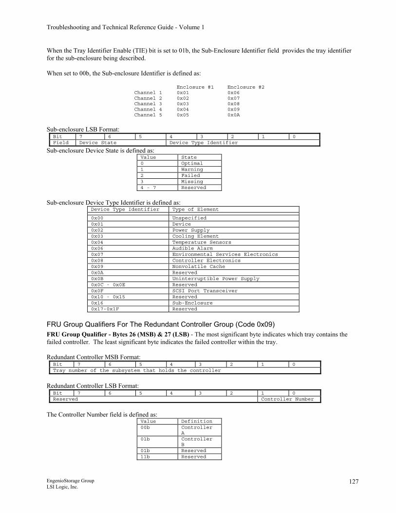
Troubleshooting and Technical Reference Guide - Volume 1
When the Tray Identifier Enable (TIE) bit is set to 01b, the Sub-Enclosure Identifier field provides the tray identifier for the sub-enclosure being described. When set to 00b, the Sub-enclosure Identifier is defined as:
Enclosure #1 Enclosure #2 Channel 1 0x01 0x06 Channel 2 0x02 0x07 Channel 3 0x03 0x08 Channel 4 0x04 0x09 Channel 5 0x05 0x0A
Sub-enclosure LSB Format:
Bit 7 6 5 4 3 2 1 0 Field Device State Device Type Identifier
Sub-enclosure Device State is defined as: Value State 0 Optimal 1 Warning 2 Failed 3 Missing 4 - 7 Reserved
Sub-enclosure Device Type Identifier is defined as:
Device Type Identifier Type of Element
0x00 Unspecified 0x01 Device 0x02 Power Supply 0x03 Cooling Element 0x04 Temperature Sensors 0x06 Audible Alarm 0x07 Environmental Services Electronics 0x08 Controller Electronics 0x09 Nonvolatile Cache 0x0A Reserved 0x0B Uninterruptible Power Supply 0x0C - 0x0E Reserved 0x0F SCSI Port Transceiver 0x10 - 0x15 Reserved 0x16 Sub-Enclosure 0x17-0x1F Reserved
FRU Group Qualifiers For The Redundant Controller Group (Code 0x09) FRU Group Qualifier - Bytes 26 (MSB) & 27 (LSB) - The most significant byte indicates which tray contains the failed controller. The least significant byte indicates the failed controller within the tray. Redundant Controller MSB Format:
Bit 7 6 5 4 3 2 1 0 Tray number of the subsystem that holds the controller
Redundant Controller LSB Format:
Bit 7 6 5 4 3 2 1 0 Reserved Controller Number
The Controller Number field is defined as:
Value Definition 00b Controller
A 01b Controller
B 01b Reserved 11b Reserved
EngenioStorage Group LSI Logic, Inc.
127
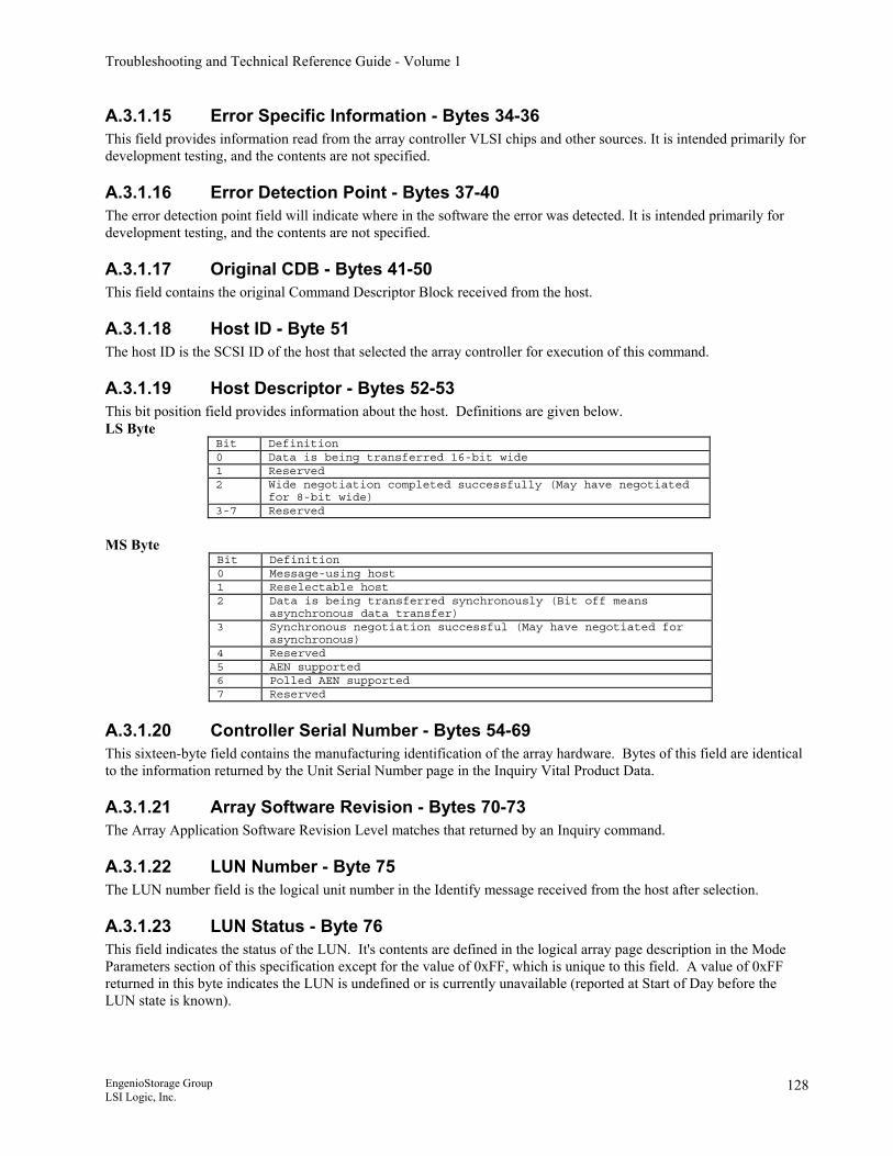
Troubleshooting and Technical Reference Guide - Volume 1
A.3.1.15 Error Specific Information - Bytes 34-36 This field provides information read from the array controller VLSI chips and other sources. It is intended primarily for development testing, and the contents are not specified.
A.3.1.16 Error Detection Point - Bytes 37-40 The error detection point field will indicate where in the software the error was detected. It is intended primarily for development testing, and the contents are not specified.
A.3.1.17 Original CDB - Bytes 41-50 This field contains the original Command Descriptor Block received from the host.
A.3.1.18 Host ID - Byte 51 The host ID is the SCSI ID of the host that selected the array controller for execution of this command.
A.3.1.19 Host Descriptor - Bytes 52-53 This bit position field provides information about the host. Definitions are given below. LS Byte
Bit Definition 0 Data is being transferred 16-bit wide 1 Reserved 2 Wide negotiation completed successfully (May have negotiated
for 8-bit wide) 3-7 Reserved
MS Byte
Bit Definition 0 Message-using host 1 Reselectable host 2 Data is being transferred synchronously (Bit off means
asynchronous data transfer) 3 Synchronous negotiation successful (May have negotiated for
asynchronous) 4 Reserved 5 AEN supported 6 Polled AEN supported 7 Reserved
A.3.1.20 Controller Serial Number - Bytes 54-69 This sixteen-byte field contains the manufacturing identification of the array hardware. Bytes of this field are identical to the information returned by the Unit Serial Number page in the Inquiry Vital Product Data.
A.3.1.21 Array Software Revision - Bytes 70-73 The Array Application Software Revision Level matches that returned by an Inquiry command.
A.3.1.22 LUN Number - Byte 75 The LUN number field is the logical unit number in the Identify message received from the host after selection.
A.3.1.23 LUN Status - Byte 76 This field indicates the status of the LUN. It's contents are defined in the logical array page description in the Mode Parameters section of this specification except for the value of 0xFF, which is unique to this field. A value of 0xFF returned in this byte indicates the LUN is undefined or is currently unavailable (reported at Start of Day before the LUN state is known).
EngenioStorage Group LSI Logic, Inc.
128
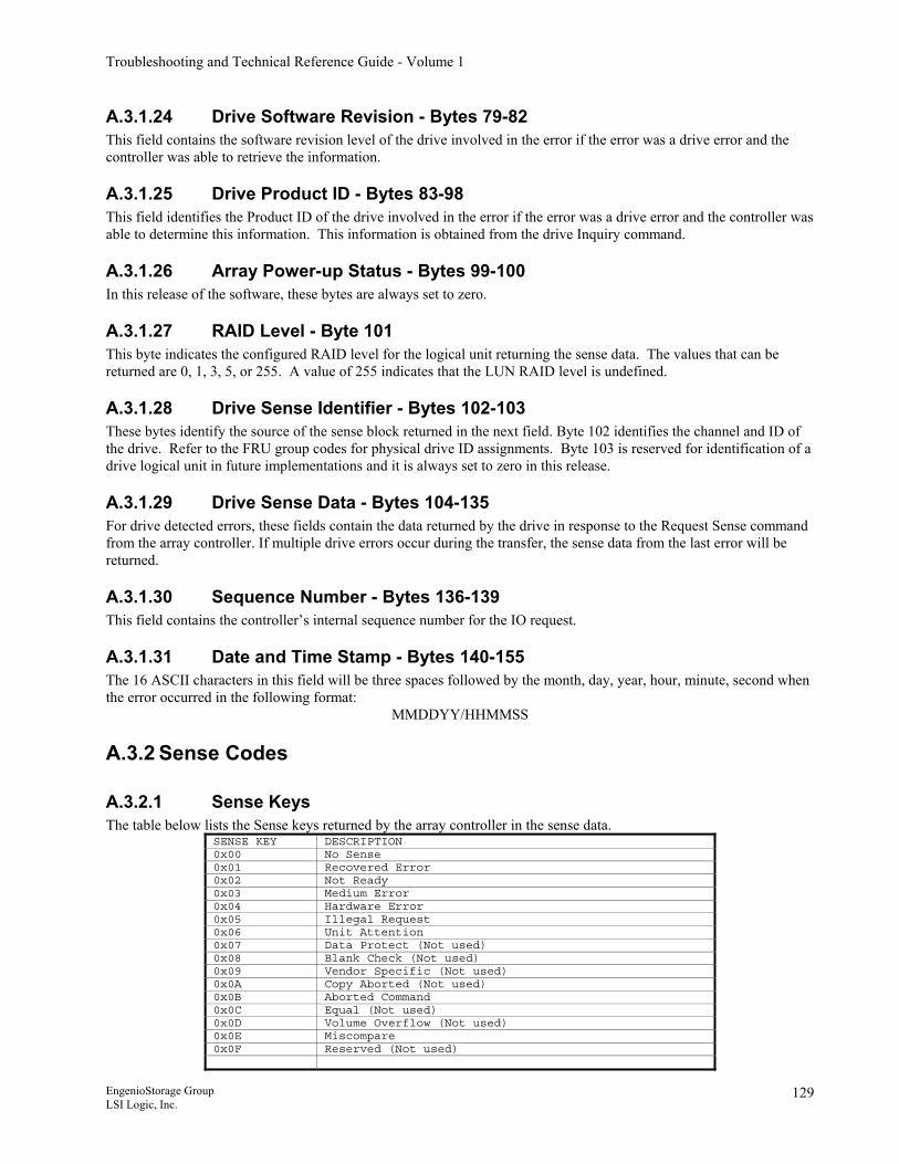
Troubleshooting and Technical Reference Guide - Volume 1
A.3.1.24 Drive Software Revision - Bytes 79-82 This field contains the software revision level of the drive involved in the error if the error was a drive error and the controller was able to retrieve the information.
A.3.1.25 Drive Product ID - Bytes 83-98 This field identifies the Product ID of the drive involved in the error if the error was a drive error and the controller was able to determine this information. This information is obtained from the drive Inquiry command.
A.3.1.26 Array Power-up Status - Bytes 99-100 In this release of the software, these bytes are always set to zero.
A.3.1.27 RAID Level - Byte 101 This byte indicates the configured RAID level for the logical unit returning the sense data. The values that can be returned are 0, 1, 3, 5, or 255. A value of 255 indicates that the LUN RAID level is undefined.
A.3.1.28 Drive Sense Identifier - Bytes 102-103 These bytes identify the source of the sense block returned in the next field. Byte 102 identifies the channel and ID of the drive. Refer to the FRU group codes for physical drive ID assignments. Byte 103 is reserved for identification of a drive logical unit in future implementations and it is always set to zero in this release.
A.3.1.29 Drive Sense Data - Bytes 104-135 For drive detected errors, these fields contain the data returned by the drive in response to the Request Sense command from the array controller. If multiple drive errors occur during the transfer, the sense data from the last error will be returned.
A.3.1.30 Sequence Number - Bytes 136-139 This field contains the controller’s internal sequence number for the IO request.
A.3.1.31 Date and Time Stamp - Bytes 140-155 The 16 ASCII characters in this field will be three spaces followed by the month, day, year, hour, minute, second when the error occurred in the following format:
MMDDYY/HHMMSS
A.3.2 Sense Codes
A.3.2.1 Sense Keys The table below lists the Sense keys returned by the array controller in the sense data.
SENSE KEY DESCRIPTION 0x00 No Sense 0x01 Recovered Error 0x02 Not Ready 0x03 Medium Error 0x04 Hardware Error 0x05 Illegal Request 0x06 Unit Attention 0x07 Data Protect (Not used) 0x08 Blank Check (Not used) 0x09 Vendor Specific (Not used) 0x0A Copy Aborted (Not used) 0x0B Aborted Command 0x0C Equal (Not used) 0x0D Volume Overflow (Not used) 0x0E Miscompare 0x0F Reserved (Not used)
EngenioStorage Group LSI Logic, Inc.
129
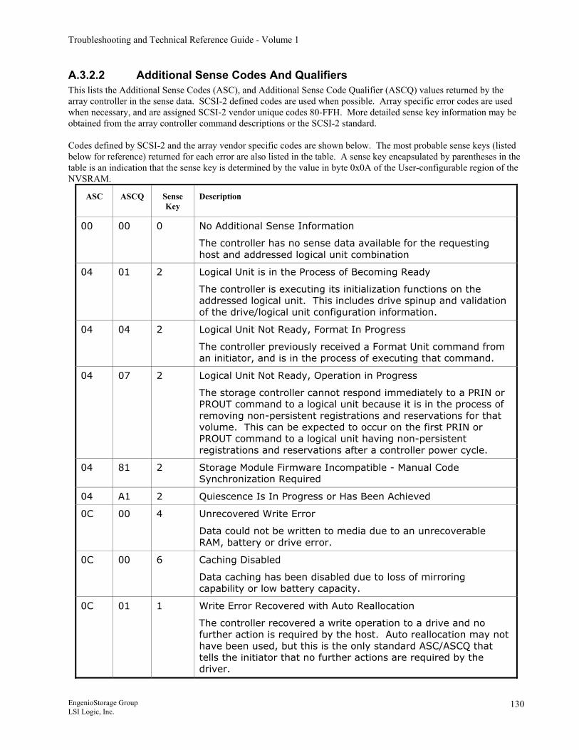
Troubleshooting and Technical Reference Guide - Volume 1
A.3.2.2 Additional Sense Codes And Qualifiers This lists the Additional Sense Codes (ASC), and Additional Sense Code Qualifier (ASCQ) values returned by the array controller in the sense data. SCSI-2 defined codes are used when possible. Array specific error codes are used when necessary, and are assigned SCSI-2 vendor unique codes 80-FFH. More detailed sense key information may be obtained from the array controller command descriptions or the SCSI-2 standard. Codes defined by SCSI-2 and the array vendor specific codes are shown below. The most probable sense keys (listed below for reference) returned for each error are also listed in the table. A sense key encapsulated by parentheses in the table is an indication that the sense key is determined by the value in byte 0x0A of the User-configurable region of the NVSRAM.
ASC ASCQ Sense Key
Description
00 00 0 No Additional Sense Information
The controller has no sense data available for the requesting host and addressed logical unit combination
04 01 2 Logical Unit is in the Process of Becoming Ready
The controller is executing its initialization functions on the addressed logical unit. This includes drive spinup and validation of the drive/logical unit configuration information.
04 04 2 Logical Unit Not Ready, Format In Progress
The controller previously received a Format Unit command from an initiator, and is in the process of executing that command.
04 07 2 Logical Unit Not Ready, Operation in Progress
The storage controller cannot respond immediately to a PRIN or PROUT command to a logical unit because it is in the process of removing non-persistent registrations and reservations for that volume. This can be expected to occur on the first PRIN or PROUT command to a logical unit having non-persistent registrations and reservations after a controller power cycle.
04 81 2 Storage Module Firmware Incompatible - Manual Code Synchronization Required
04 A1 2 Quiescence Is In Progress or Has Been Achieved
0C 00 4 Unrecovered Write Error
Data could not be written to media due to an unrecoverable RAM, battery or drive error.
0C 00 6 Caching Disabled
Data caching has been disabled due to loss of mirroring capability or low battery capacity.
0C 01 1 Write Error Recovered with Auto Reallocation
The controller recovered a write operation to a drive and no further action is required by the host. Auto reallocation may not have been used, but this is the only standard ASC/ASCQ that tells the initiator that no further actions are required by the driver.
EngenioStorage Group LSI Logic, Inc.
130
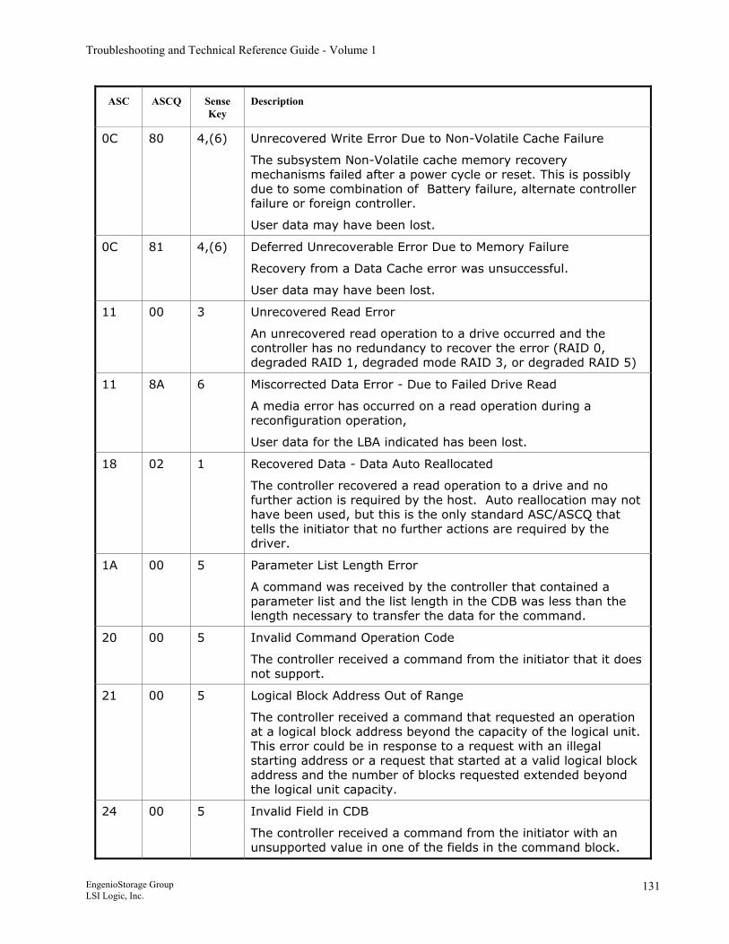
Troubleshooting and Technical Reference Guide - Volume 1
ASC ASCQ Sense Key
Description
0C 80 4,(6) Unrecovered Write Error Due to Non-Volatile Cache Failure
The subsystem Non-Volatile cache memory recovery mechanisms failed after a power cycle or reset. This is possibly due to some combination of Battery failure, alternate controller failure or foreign controller.
User data may have been lost.
0C 81 4,(6) Deferred Unrecoverable Error Due to Memory Failure
Recovery from a Data Cache error was unsuccessful.
User data may have been lost.
11 00 3 Unrecovered Read Error
An unrecovered read operation to a drive occurred and the controller has no redundancy to recover the error (RAID 0, degraded RAID 1, degraded mode RAID 3, or degraded RAID 5)
11 8A 6 Miscorrected Data Error - Due to Failed Drive Read
A media error has occurred on a read operation during a reconfiguration operation,
User data for the LBA indicated has been lost.
18 02 1 Recovered Data - Data Auto Reallocated
The controller recovered a read operation to a drive and no further action is required by the host. Auto reallocation may not have been used, but this is the only standard ASC/ASCQ that tells the initiator that no further actions are required by the driver.
1A 00 5 Parameter List Length Error
A command was received by the controller that contained a parameter list and the list length in the CDB was less than the length necessary to transfer the data for the command.
20 00 5 Invalid Command Operation Code
The controller received a command from the initiator that it does not support.
21 00 5 Logical Block Address Out of Range
The controller received a command that requested an operation at a logical block address beyond the capacity of the logical unit. This error could be in response to a request with an illegal starting address or a request that started at a valid logical block address and the number of blocks requested extended beyond the logical unit capacity.
24 00 5 Invalid Field in CDB
The controller received a command from the initiator with an unsupported value in one of the fields in the command block.
EngenioStorage Group LSI Logic, Inc.
131
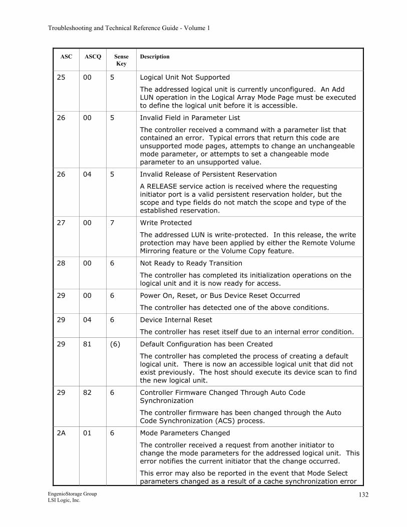
Troubleshooting and Technical Reference Guide - Volume 1
ASC ASCQ Sense Key
Description
25 00 5 Logical Unit Not Supported
The addressed logical unit is currently unconfigured. An Add LUN operation in the Logical Array Mode Page must be executed to define the logical unit before it is accessible.
26 00 5 Invalid Field in Parameter List
The controller received a command with a parameter list that contained an error. Typical errors that return this code are unsupported mode pages, attempts to change an unchangeable mode parameter, or attempts to set a changeable mode parameter to an unsupported value.
26 04 5 Invalid Release of Persistent Reservation
A RELEASE service action is received where the requesting initiator port is a valid persistent reservation holder, but the scope and type fields do not match the scope and type of the established reservation.
27 00 7 Write Protected
The addressed LUN is write-protected. In this release, the write protection may have been applied by either the Remote Volume Mirroring feature or the Volume Copy feature.
28 00 6 Not Ready to Ready Transition
The controller has completed its initialization operations on the logical unit and it is now ready for access.
29 00 6 Power On, Reset, or Bus Device Reset Occurred
The controller has detected one of the above conditions.
29 04 6 Device Internal Reset
The controller has reset itself due to an internal error condition.
29 81 (6) Default Configuration has been Created
The controller has completed the process of creating a default logical unit. There is now an accessible logical unit that did not exist previously. The host should execute its device scan to find the new logical unit.
29 82 6 Controller Firmware Changed Through Auto Code Synchronization
The controller firmware has been changed through the Auto Code Synchronization (ACS) process.
2A 01 6 Mode Parameters Changed
The controller received a request from another initiator to change the mode parameters for the addressed logical unit. This error notifies the current initiator that the change occurred.
This error may also be reported in the event that Mode Select parameters changed as a result of a cache synchronization error
EngenioStorage Group LSI Logic, Inc.
132
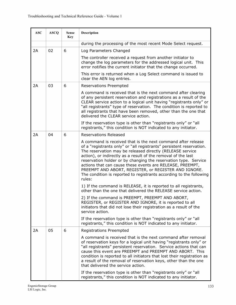
Troubleshooting and Technical Reference Guide - Volume 1
ASC ASCQ Sense Key
Description
during the processing of the most recent Mode Select request.
2A 02 6 Log Parameters Changed
The controller received a request from another initiator to change the log parameters for the addressed logical unit. This error notifies the current initiator that the change occurred.
This error is returned when a Log Select command is issued to clear the AEN log entries.
2A 03 6 Reservations Preempted
A command is received that is the next command after clearing of any persistent reservation and registrations as a result of the CLEAR service action to a logical unit having “registrants only” or “all registrants” type of reservation. The condition is reported to all registrants that have been removed, other than the one that delivered the CLEAR service action.
If the reservation type is other than “registrants only” or “all registrants,” this condition is NOT indicated to any initiator.
2A 04 6 Reservations Released
A command is received that is the next command after release of a “registrants only” or “all registrants” persistent reservation. The reservation may be released directly (RELEASE service action), or indirectly as a result of the removal of the last reservation holder or by changing the reservation type. Service actions that can cause these events are RELEASE, PREEMPT, PREEMPT AND ABORT, REGISTER, or REGISTER AND IGNORE. The condition is reported to registrants according to the following rules:
1) If the command is RELEASE, it is reported to all registrants, other than the one that delivered the RELEASE service action.
2) If the command is PREEMPT, PREEMPT AND ABORT, REGISTER, or REGISTER AND IGNORE, it is reported to all initiators that did not lose their registration as a result of the service action.
If the reservation type is other than “registrants only” or “all registrants,” this condition is NOT indicated to any initiator.
2A 05 6 Registrations Preempted
A command is received that is the next command after removal of reservation keys for a logical unit having “registrants only” or “all registrants” persistent reservation. Service actions that can cause this event are PREEMPT and PREEMPT AND ABORT. This condition is reported to all initiators that lost their registration as a result of the removal of reservation keys, other than the one that delivered the service action.
If the reservation type is other than “registrants only” or “all registrants,” this condition is NOT indicated to any initiator.
EngenioStorage Group LSI Logic, Inc.
133
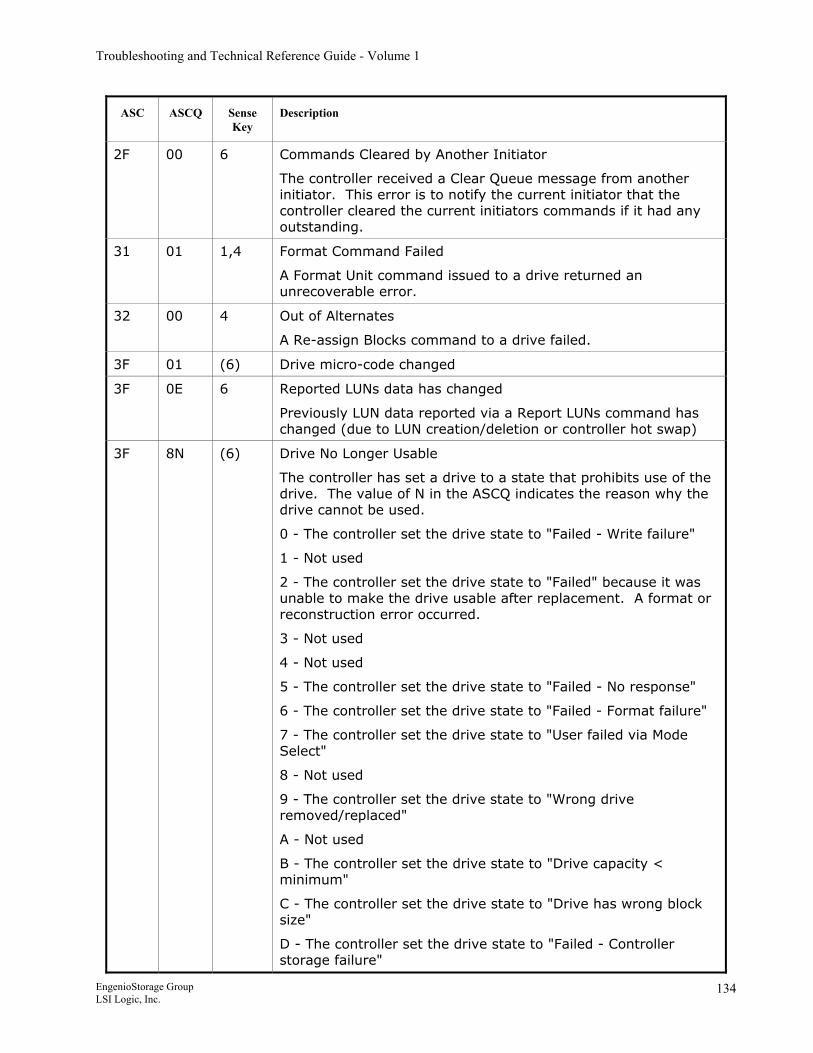
Troubleshooting and Technical Reference Guide - Volume 1
ASC ASCQ Sense Key
Description
2F 00 6 Commands Cleared by Another Initiator
The controller received a Clear Queue message from another initiator. This error is to notify the current initiator that the controller cleared the current initiators commands if it had any outstanding.
31 01 1,4 Format Command Failed
A Format Unit command issued to a drive returned an unrecoverable error.
32 00 4 Out of Alternates
A Re-assign Blocks command to a drive failed.
3F 01 (6) Drive micro-code changed
3F 0E 6 Reported LUNs data has changed
Previously LUN data reported via a Report LUNs command has changed (due to LUN creation/deletion or controller hot swap)
3F 8N (6) Drive No Longer Usable
The controller has set a drive to a state that prohibits use of the drive. The value of N in the ASCQ indicates the reason why the drive cannot be used.
0 - The controller set the drive state to "Failed - Write failure"
1 - Not used
2 - The controller set the drive state to "Failed" because it was unable to make the drive usable after replacement. A format or reconstruction error occurred.
3 - Not used
4 - Not used
5 - The controller set the drive state to "Failed - No response"
6 - The controller set the drive state to "Failed - Format failure"
7 - The controller set the drive state to "User failed via Mode Select"
8 - Not used
9 - The controller set the drive state to "Wrong drive removed/replaced"
A - Not used
B - The controller set the drive state to "Drive capacity < minimum"
C - The controller set the drive state to "Drive has wrong block size"
D - The controller set the drive state to "Failed - Controller storage failure"
EngenioStorage Group LSI Logic, Inc.
134
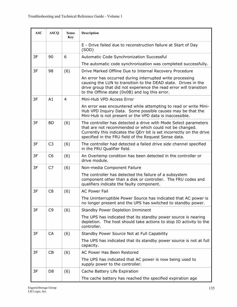
Troubleshooting and Technical Reference Guide - Volume 1
ASC ASCQ Sense Key
Description
E - Drive failed due to reconstruction failure at Start of Day (SOD)
3F 90 6 Automatic Code Synchronization Successful
The automatic code synchronization was completed successfully.
3F 98 (6) Drive Marked Offline Due to Internal Recovery Procedure
An error has occurred during interrupted write processing causing the LUN to transition to the DEAD state. Drives in the drive group that did not experience the read error will transition to the Offline state (0x0B) and log this error.
3F A1 4 Mini-Hub VPD Access Error
An error was encountered while attempting to read or write Mini-Hub VPD Inquiry Data. Some possible causes may be that the Mini-Hub is not present or the VPD data is inaccessible.
3F BD (6) The controller has detected a drive with Mode Select parameters that are not recommended or which could not be changed. Currently this indicates the QErr bit is set incorrectly on the drive specified in the FRU field of the Request Sense data.
3F C3 (6) The controller had detected a failed drive side channel specified in the FRU Qualifier field.
3F C6 (6) An Overtemp condition has been detected in the controller or drive module.
3F C7 (6) Non-media Component Failure
The controller has detected the failure of a subsystem component other than a disk or controller. The FRU codes and qualifiers indicate the faulty component.
3F C8 (6) AC Power Fail
The Uninterruptible Power Source has indicated that AC power is no longer present and the UPS has switched to standby power.
3F C9 (6) Standby Power Depletion Imminent
The UPS has indicated that its standby power source is nearing depletion. The host should take actions to stop IO activity to the controller.
3F CA (6) Standby Power Source Not at Full Capability
The UPS has indicated that its standby power source is not at full capacity.
3F CB (6) AC Power Has Been Restored
The UPS has indicated that AC power is now being used to supply power to the controller.
3F D8 (6) Cache Battery Life Expiration
The cache battery has reached the specified expiration age
EngenioStorage Group LSI Logic, Inc.
135
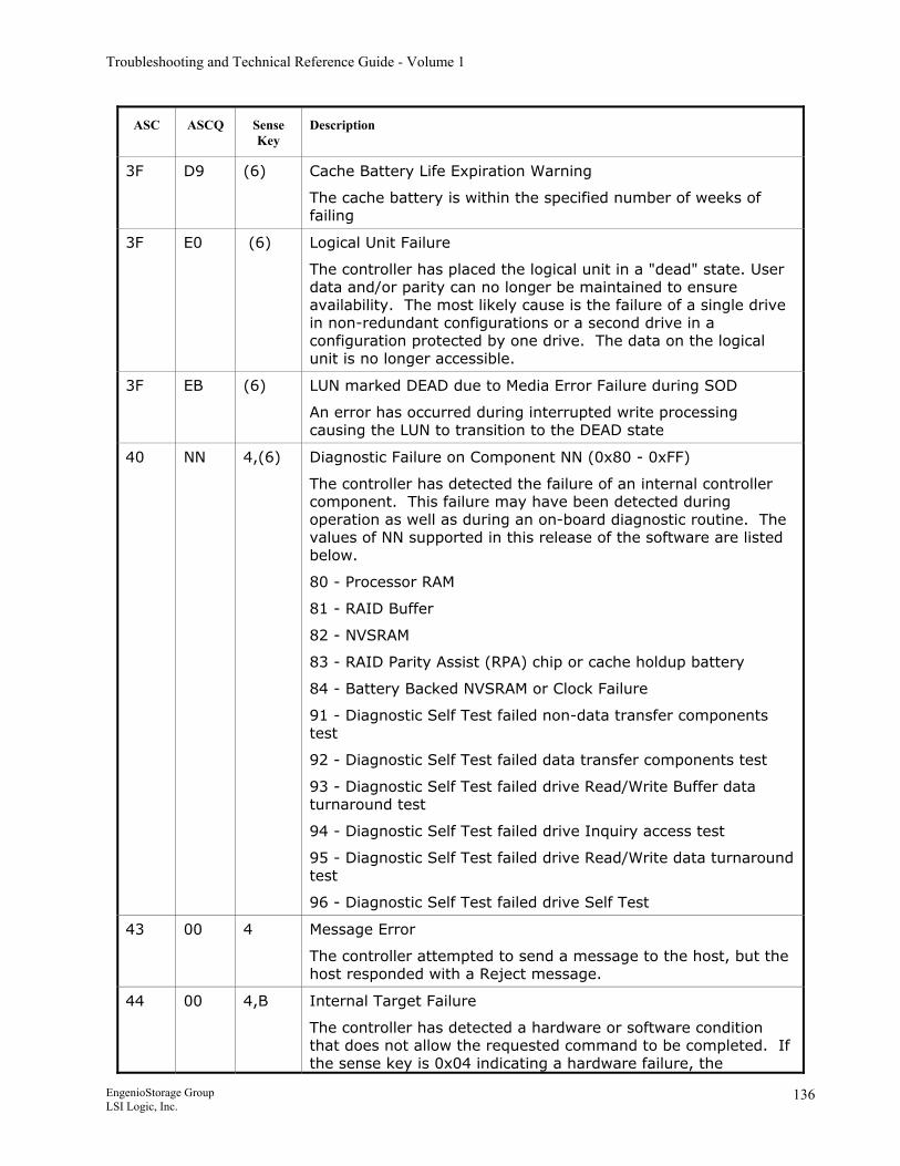
Troubleshooting and Technical Reference Guide - Volume 1
ASC ASCQ Sense Key
Description
3F D9 (6) Cache Battery Life Expiration Warning
The cache battery is within the specified number of weeks of failing
3F E0 (6) Logical Unit Failure
The controller has placed the logical unit in a "dead" state. User data and/or parity can no longer be maintained to ensure availability. The most likely cause is the failure of a single drive in non-redundant configurations or a second drive in a configuration protected by one drive. The data on the logical unit is no longer accessible.
3F EB (6) LUN marked DEAD due to Media Error Failure during SOD
An error has occurred during interrupted write processing causing the LUN to transition to the DEAD state
40 NN 4,(6) Diagnostic Failure on Component NN (0x80 - 0xFF)
The controller has detected the failure of an internal controller component. This failure may have been detected during operation as well as during an on-board diagnostic routine. The values of NN supported in this release of the software are listed below.
80 - Processor RAM
81 - RAID Buffer
82 - NVSRAM
83 - RAID Parity Assist (RPA) chip or cache holdup battery
84 - Battery Backed NVSRAM or Clock Failure
91 - Diagnostic Self Test failed non-data transfer components test
92 - Diagnostic Self Test failed data transfer components test
93 - Diagnostic Self Test failed drive Read/Write Buffer data turnaround test
94 - Diagnostic Self Test failed drive Inquiry access test
95 - Diagnostic Self Test failed drive Read/Write data turnaround test
96 - Diagnostic Self Test failed drive Self Test
43 00 4 Message Error
The controller attempted to send a message to the host, but the host responded with a Reject message.
44 00 4,B Internal Target Failure
The controller has detected a hardware or software condition that does not allow the requested command to be completed. If the sense key is 0x04 indicating a hardware failure, the
EngenioStorage Group LSI Logic, Inc.
136
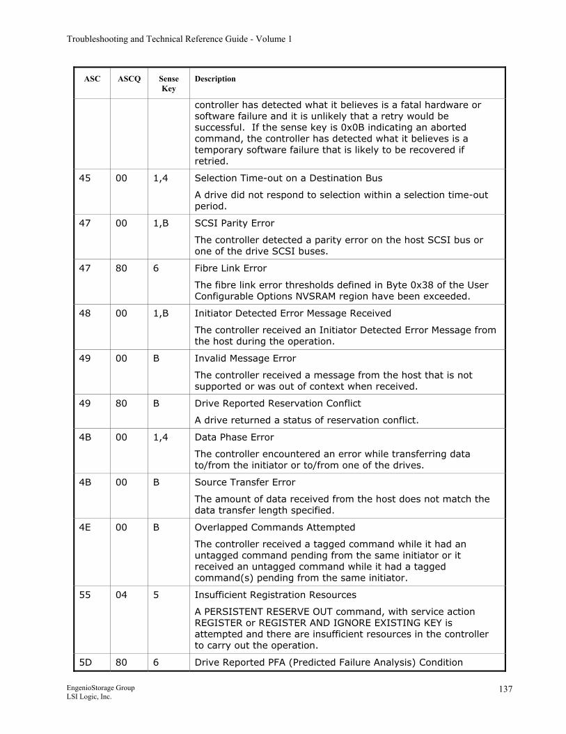
Troubleshooting and Technical Reference Guide - Volume 1
ASC ASCQ Sense Key
Description
controller has detected what it believes is a fatal hardware or software failure and it is unlikely that a retry would be successful. If the sense key is 0x0B indicating an aborted command, the controller has detected what it believes is a temporary software failure that is likely to be recovered if retried.
45 00 1,4 Selection Time-out on a Destination Bus
A drive did not respond to selection within a selection time-out period.
47 00 1,B SCSI Parity Error
The controller detected a parity error on the host SCSI bus or one of the drive SCSI buses.
47 80 6 Fibre Link Error
The fibre link error thresholds defined in Byte 0x38 of the User Configurable Options NVSRAM region have been exceeded.
48 00 1,B Initiator Detected Error Message Received
The controller received an Initiator Detected Error Message from the host during the operation.
49 00 B Invalid Message Error
The controller received a message from the host that is not supported or was out of context when received.
49 80 B Drive Reported Reservation Conflict
A drive returned a status of reservation conflict.
4B 00 1,4 Data Phase Error
The controller encountered an error while transferring data to/from the initiator or to/from one of the drives.
4B 00 B Source Transfer Error
The amount of data received from the host does not match the data transfer length specified.
4E 00 B Overlapped Commands Attempted
The controller received a tagged command while it had an untagged command pending from the same initiator or it received an untagged command while it had a tagged command(s) pending from the same initiator.
55 04 5 Insufficient Registration Resources
A PERSISTENT RESERVE OUT command, with service action REGISTER or REGISTER AND IGNORE EXISTING KEY is attempted and there are insufficient resources in the controller to carry out the operation.
5D 80 6 Drive Reported PFA (Predicted Failure Analysis) Condition
EngenioStorage Group LSI Logic, Inc.
137
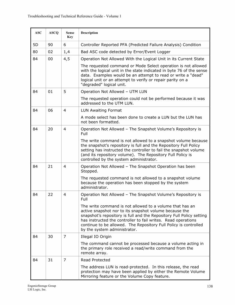
Troubleshooting and Technical Reference Guide - Volume 1
ASC ASCQ Sense Key
Description
5D 90 6 Controller Reported PFA (Predicted Failure Analysis) Condition
80 02 1,4 Bad ASC code detected by Error/Event Logger
84 00 4,5 Operation Not Allowed With the Logical Unit in its Current State
The requested command or Mode Select operation is not allowed with the logical unit in the state indicated in byte 76 of the sense data. Examples would be an attempt to read or write a "dead" logical unit or an attempt to verify or repair parity on a "degraded" logical unit.
84 01 5 Operation Not Allowed – UTM LUN
The requested operation could not be performed because it was addressed to the UTM LUN.
84 06 4 LUN Awaiting Format
A mode select has been done to create a LUN but the LUN has not been formatted.
84 20 4 Operation Not Allowed – The Snapshot Volume’s Repository is Full
The write command is not allowed to a snapshot volume because the snapshot’s repository is full and the Repository Full Policy setting has instructed the controller to fail the snapshot volume (and its repository volume). The Repository Full Policy is controlled by the system administrator.
84 21 4 Operation Not Allowed – The Snapshot Operation has been Stopped.
The requested command is not allowed to a snapshot volume because the operation has been stopped by the system administrator.
84 22 4 Operation Not Allowed – The Snapshot Volume’s Repository is Full
The write command is not allowed to a volume that has an active snapshot nor to its snapshot volume because the snapshot’s repository is full and the Repository Full Policy setting has instructed the controller to fail writes. Read operations continue to be allowed. The Repository Full Policy is controlled by the system administrator.
84 30 7 Illegal IO Origin
The command cannot be processed because a volume acting in the primary role received a read/write command from the remote array.
84 31 7 Read Protected
The address LUN is read-protected. In this release, the read protection may have been applied by either the Remote Volume Mirroring feature or the Volume Copy feature.
EngenioStorage Group LSI Logic, Inc.
138
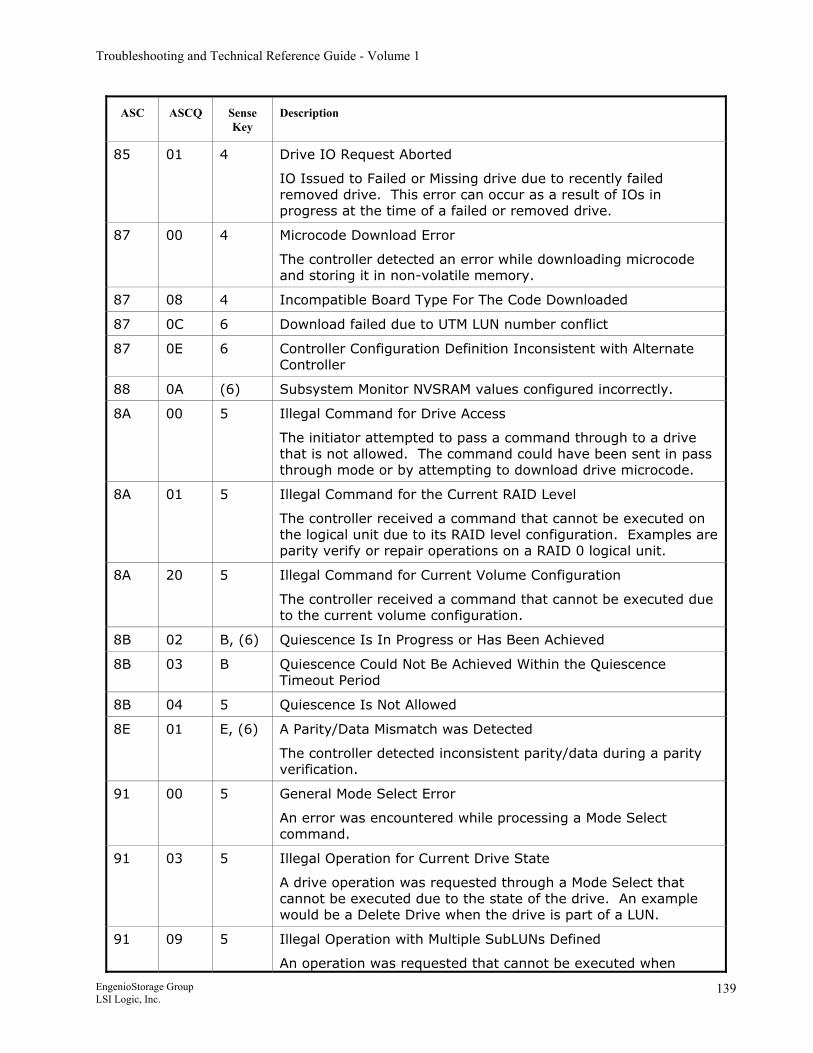
Troubleshooting and Technical Reference Guide - Volume 1
ASC ASCQ Sense Key
Description
85 01 4 Drive IO Request Aborted
IO Issued to Failed or Missing drive due to recently failed removed drive. This error can occur as a result of IOs in progress at the time of a failed or removed drive.
87 00 4 Microcode Download Error
The controller detected an error while downloading microcode and storing it in non-volatile memory.
87 08 4 Incompatible Board Type For The Code Downloaded
87 0C 6 Download failed due to UTM LUN number conflict
87 0E 6 Controller Configuration Definition Inconsistent with Alternate Controller
88 0A (6) Subsystem Monitor NVSRAM values configured incorrectly.
8A 00 5 Illegal Command for Drive Access
The initiator attempted to pass a command through to a drive that is not allowed. The command could have been sent in pass through mode or by attempting to download drive microcode.
8A 01 5 Illegal Command for the Current RAID Level
The controller received a command that cannot be executed on the logical unit due to its RAID level configuration. Examples are parity verify or repair operations on a RAID 0 logical unit.
8A 20 5 Illegal Command for Current Volume Configuration
The controller received a command that cannot be executed due to the current volume configuration.
8B 02 B, (6) Quiescence Is In Progress or Has Been Achieved
8B 03 B Quiescence Could Not Be Achieved Within the Quiescence Timeout Period
8B 04 5 Quiescence Is Not Allowed
8E 01 E, (6) A Parity/Data Mismatch was Detected
The controller detected inconsistent parity/data during a parity verification.
91 00 5 General Mode Select Error
An error was encountered while processing a Mode Select command.
91 03 5 Illegal Operation for Current Drive State
A drive operation was requested through a Mode Select that cannot be executed due to the state of the drive. An example would be a Delete Drive when the drive is part of a LUN.
91 09 5 Illegal Operation with Multiple SubLUNs Defined
An operation was requested that cannot be executed when
EngenioStorage Group LSI Logic, Inc.
139
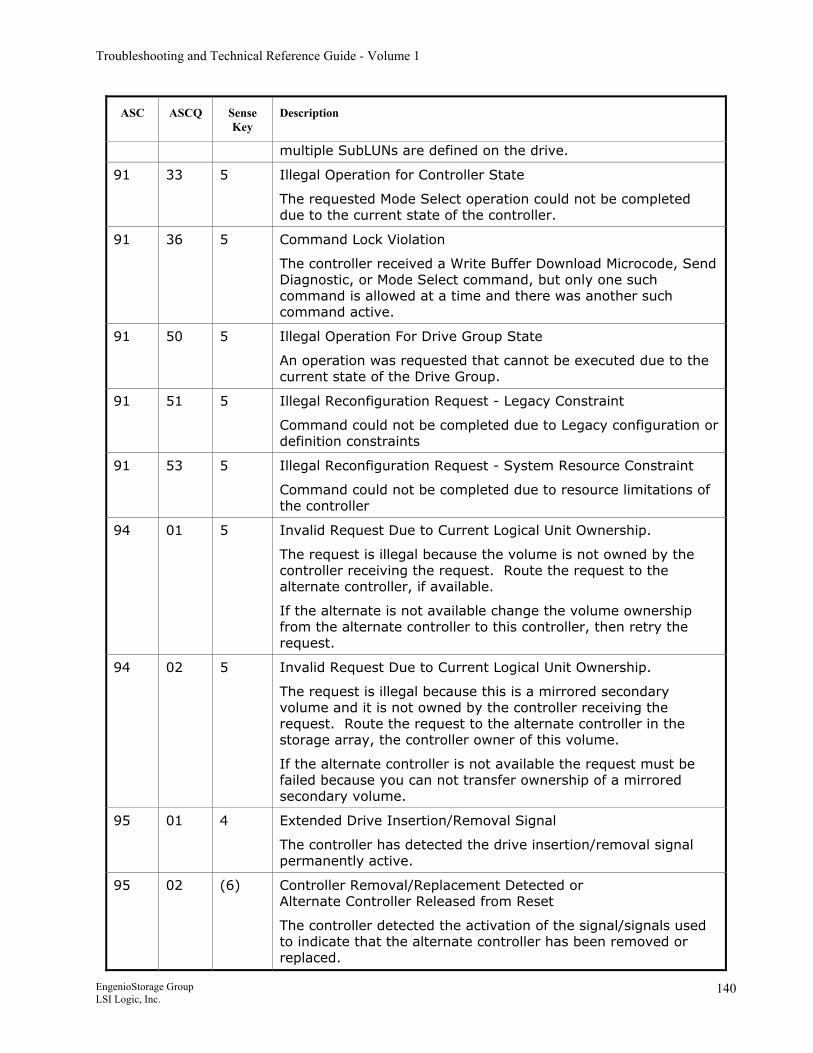
Troubleshooting and Technical Reference Guide - Volume 1
ASC ASCQ Sense Key
Description
multiple SubLUNs are defined on the drive.
91 33 5 Illegal Operation for Controller State
The requested Mode Select operation could not be completed due to the current state of the controller.
91 36 5 Command Lock Violation
The controller received a Write Buffer Download Microcode, Send Diagnostic, or Mode Select command, but only one such command is allowed at a time and there was another such command active.
91 50 5 Illegal Operation For Drive Group State
An operation was requested that cannot be executed due to the current state of the Drive Group.
91 51 5 Illegal Reconfiguration Request - Legacy Constraint
Command could not be completed due to Legacy configuration or definition constraints
91 53 5 Illegal Reconfiguration Request - System Resource Constraint
Command could not be completed due to resource limitations of the controller
94 01 5 Invalid Request Due to Current Logical Unit Ownership.
The request is illegal because the volume is not owned by the controller receiving the request. Route the request to the alternate controller, if available.
If the alternate is not available change the volume ownership from the alternate controller to this controller, then retry the request.
94 02 5 Invalid Request Due to Current Logical Unit Ownership.
The request is illegal because this is a mirrored secondary volume and it is not owned by the controller receiving the request. Route the request to the alternate controller in the storage array, the controller owner of this volume.
If the alternate controller is not available the request must be failed because you can not transfer ownership of a mirrored secondary volume.
95 01 4 Extended Drive Insertion/Removal Signal
The controller has detected the drive insertion/removal signal permanently active.
95 02 (6) Controller Removal/Replacement Detected or Alternate Controller Released from Reset
The controller detected the activation of the signal/signals used to indicate that the alternate controller has been removed or replaced.
EngenioStorage Group LSI Logic, Inc.
140
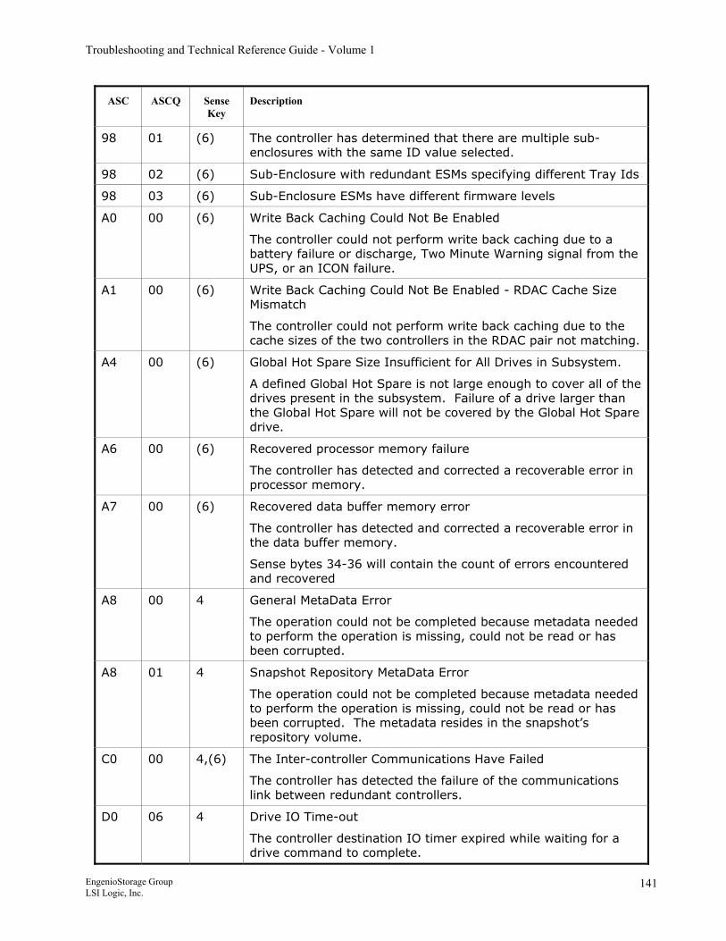
Troubleshooting and Technical Reference Guide - Volume 1
ASC ASCQ Sense Key
Description
98 01 (6) The controller has determined that there are multiple sub-enclosures with the same ID value selected.
98 02 (6) Sub-Enclosure with redundant ESMs specifying different Tray Ids
98 03 (6) Sub-Enclosure ESMs have different firmware levels
A0 00 (6) Write Back Caching Could Not Be Enabled
The controller could not perform write back caching due to a battery failure or discharge, Two Minute Warning signal from the UPS, or an ICON failure.
A1 00 (6) Write Back Caching Could Not Be Enabled - RDAC Cache Size Mismatch
The controller could not perform write back caching due to the cache sizes of the two controllers in the RDAC pair not matching.
A4 00 (6) Global Hot Spare Size Insufficient for All Drives in Subsystem.
A defined Global Hot Spare is not large enough to cover all of the drives present in the subsystem. Failure of a drive larger than the Global Hot Spare will not be covered by the Global Hot Spare drive.
A6 00 (6) Recovered processor memory failure
The controller has detected and corrected a recoverable error in processor memory.
A7 00 (6) Recovered data buffer memory error
The controller has detected and corrected a recoverable error in the data buffer memory.
Sense bytes 34-36 will contain the count of errors encountered and recovered
A8 00 4 General MetaData Error
The operation could not be completed because metadata needed to perform the operation is missing, could not be read or has been corrupted.
A8 01 4 Snapshot Repository MetaData Error
The operation could not be completed because metadata needed to perform the operation is missing, could not be read or has been corrupted. The metadata resides in the snapshot’s repository volume.
C0 00 4,(6) The Inter-controller Communications Have Failed
The controller has detected the failure of the communications link between redundant controllers.
D0 06 4 Drive IO Time-out
The controller destination IO timer expired while waiting for a drive command to complete.
EngenioStorage Group LSI Logic, Inc.
141
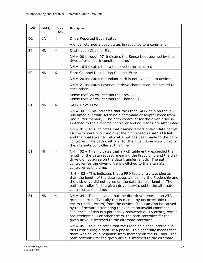
Troubleshooting and Technical Reference Guide - Volume 1
ASC ASCQ Sense Key
Description
D1 0A 4 Drive Reported Busy Status
A drive returned a busy status in response to a command.
E0 NN 4 Destination Channel Error
NN = 00 through 07 indicates the Sense Key returned by the drive after a check condition status
NN = 10 indicates that a bus level error occurred
E0 NN 6 Fibre Channel Destination Channel Error
NN = 20 indicates redundant path is not available to devices
NN = 21 indicates destination drive channels are connected to each other
Sense Byte 26 will contain the Tray ID. Sense Byte 27 will contain the Channel ID.
E1 NN 4 SATA Drive Error
NN = 00 – This indicates that the Frodo SATA chip on the PCI bus timed out while fetching a command descriptor block from ring buffer memory. The path controller for the given drive is switched to the alternate controller and no retries are attempted.
NN = 01 – This indicates that framing errors and/or data packet CRC errors are occurring over the high speed serial SATA link and the final (twelfth) retry attempt has been made to the path controller. The path controller for the given drive is switched to the alternate controller at this time.
E1 NN 4 NN = 02 – This indicates that a PRD table entry exceeded the length of the data request, meaning the Frodo chip and the disk drive did not agree on the data transfer length. The path controller for the given drive is switched to the alternate controller at this time.
NN = 03 - This indicates that a PRD table entry was shorter than the length of the data request, meaning the Frodo chip and the disk drive did not agree on the data transfer length. The path controller for the given drive is switched to the alternate controller at this time.
E1 NN 4 NN = 04 – This indicates that the disk drive reported an ATA protocol error. Typically this is caused by uncorrectable read errors (media errors) from the device. This can also be caused by the firmware attempting to execute an invalid command sequence. If this is a potentially recoverable ATA errors, retries are attempted. For other errors, the path controller for the given drive is switched to the alternate controller.
NN = 05 – This indicates that the Frodo chip encountered a PCI Bus Error during a data DMA phase. This generally means that there was no valid response from memory on the PCI bus. The path controller for the given drive is switched to the alternate
EngenioStorage Group LSI Logic, Inc.
142
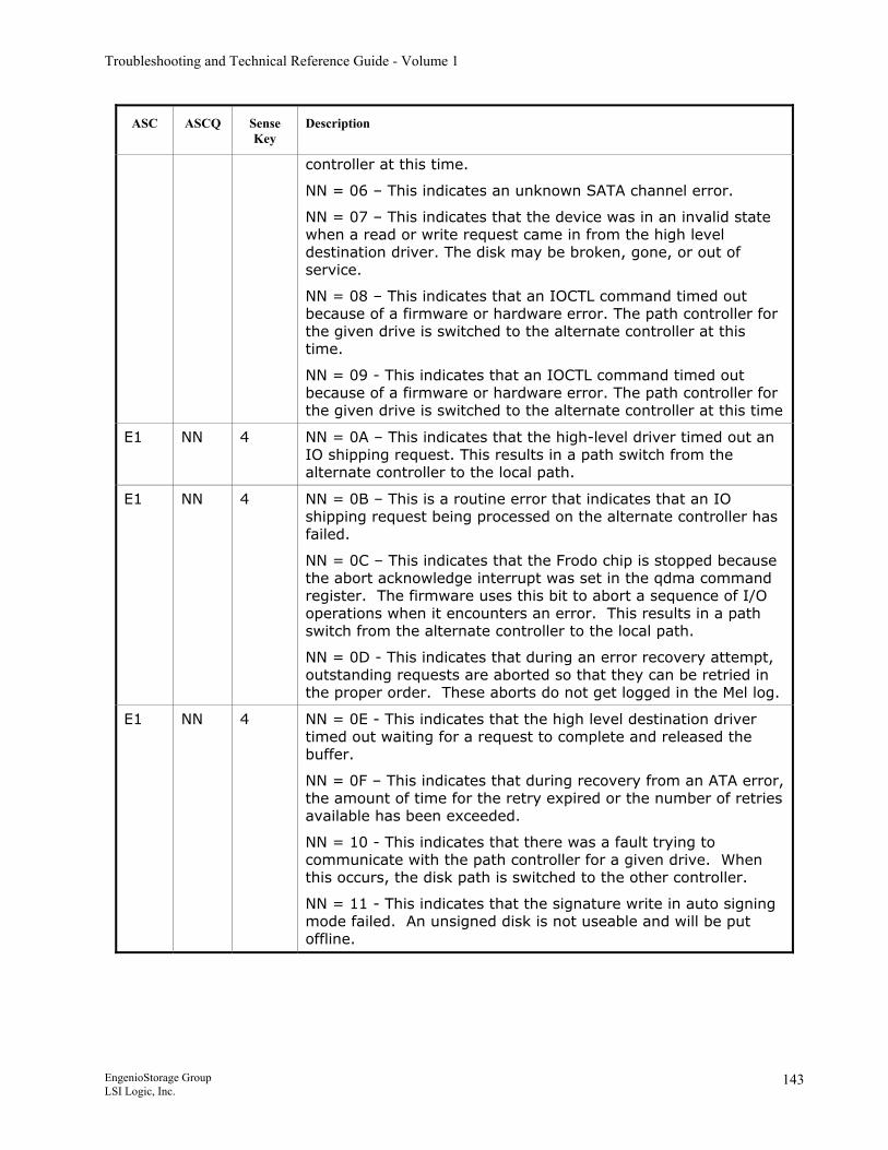
Troubleshooting and Technical Reference Guide - Volume 1
ASC ASCQ Sense Key
Description
controller at this time.
NN = 06 – This indicates an unknown SATA channel error.
NN = 07 – This indicates that the device was in an invalid state when a read or write request came in from the high level destination driver. The disk may be broken, gone, or out of service.
NN = 08 – This indicates that an IOCTL command timed out because of a firmware or hardware error. The path controller for the given drive is switched to the alternate controller at this time.
NN = 09 - This indicates that an IOCTL command timed out because of a firmware or hardware error. The path controller for the given drive is switched to the alternate controller at this time
E1 NN 4 NN = 0A – This indicates that the high-level driver timed out an IO shipping request. This results in a path switch from the alternate controller to the local path.
E1 NN 4 NN = 0B – This is a routine error that indicates that an IO shipping request being processed on the alternate controller has failed.
NN = 0C – This indicates that the Frodo chip is stopped because the abort acknowledge interrupt was set in the qdma command register. The firmware uses this bit to abort a sequence of I/O operations when it encounters an error. This results in a path switch from the alternate controller to the local path.
NN = 0D - This indicates that during an error recovery attempt, outstanding requests are aborted so that they can be retried in the proper order. These aborts do not get logged in the Mel log.
E1 NN 4 NN = 0E - This indicates that the high level destination driver timed out waiting for a request to complete and released the buffer.
NN = 0F – This indicates that during recovery from an ATA error, the amount of time for the retry expired or the number of retries available has been exceeded.
NN = 10 - This indicates that there was a fault trying to communicate with the path controller for a given drive. When this occurs, the disk path is switched to the other controller.
NN = 11 - This indicates that the signature write in auto signing mode failed. An unsigned disk is not useable and will be put offline.
EngenioStorage Group LSI Logic, Inc.
143
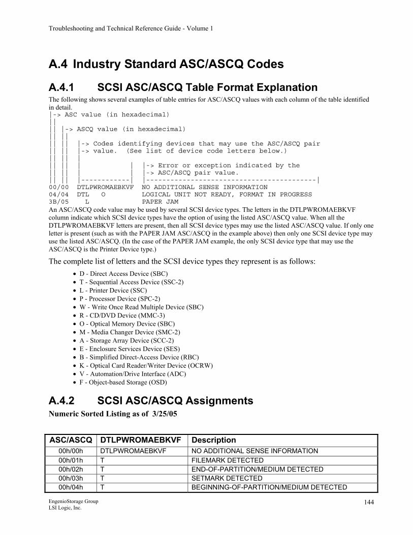
Troubleshooting and Technical Reference Guide - Volume 1
A.4 Industry Standard ASC/ASCQ Codes
A.4.1 SCSI ASC/ASCQ Table Format Explanation The following shows several examples of table entries for ASC/ASCQ values with each column of the table identified in detail. |-> ASC value (in hexadecimal) || || |-> ASCQ value (in hexadecimal) || || || || |-> Codes identifying devices that may use the ASC/ASCQ pair || || |-> value. (See list of device code letters below.) || || | || || | | |-> Error or exception indicated by the || || | | |-> ASC/ASCQ pair value. || || |------------| |------------------------------------------| 00/00 DTLPWROMAEBKVF NO ADDITIONAL SENSE INFORMATION 04/04 DTL O LOGICAL UNIT NOT READY, FORMAT IN PROGRESS 3B/05 L PAPER JAM An ASC/ASCQ code value may be used by several SCSI device types. The letters in the DTLPWROMAEBKVF column indicate which SCSI device types have the option of using the listed ASC/ASCQ value. When all the DTLPWROMAEBKVF letters are present, then all SCSI device types may use the listed ASC/ASCQ value. If only one letter is present (such as with the PAPER JAM ASC/ASCQ in the example above) then only one SCSI device type may use the listed ASC/ASCQ. (In the case of the PAPER JAM example, the only SCSI device type that may use the ASC/ASCQ is the Printer Device type.)
The complete list of letters and the SCSI device types they represent is as follows: • D - Direct Access Device (SBC) • T - Sequential Access Device (SSC-2) • L - Printer Device (SSC) • P - Processor Device (SPC-2) • W - Write Once Read Multiple Device (SBC) • R - CD/DVD Device (MMC-3) • O - Optical Memory Device (SBC) • M - Media Changer Device (SMC-2) • A - Storage Array Device (SCC-2) • E - Enclosure Services Device (SES) • B - Simplified Direct-Access Device (RBC) • K - Optical Card Reader/Writer Device (OCRW) • V - Automation/Drive Interface (ADC) • F - Object-based Storage (OSD)
A.4.2 SCSI ASC/ASCQ Assignments Numeric Sorted Listing as of 3/25/05 ASC/ASCQ DTLPWROMAEBKVF Description
00h/00h DTLPWROMAEBKVF NO ADDITIONAL SENSE INFORMATION 00h/01h T FILEMARK DETECTED 00h/02h T END-OF-PARTITION/MEDIUM DETECTED 00h/03h T SETMARK DETECTED 00h/04h T BEGINNING-OF-PARTITION/MEDIUM DETECTED
EngenioStorage Group LSI Logic, Inc.
144
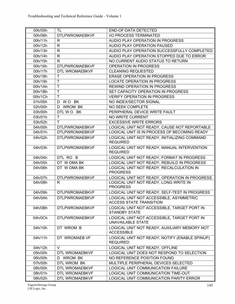
Troubleshooting and Technical Reference Guide - Volume 1
00h/05h TL END-OF-DATA DETECTED 00h/06h DTLPWROMAEBKVF I/O PROCESS TERMINATED 00h/11h R AUDIO PLAY OPERATION IN PROGRESS 00h/12h R AUDIO PLAY OPERATION PAUSED 00h/13h R AUDIO PLAY OPERATION SUCCESSFULLY COMPLETED00h/14h R AUDIO PLAY OPERATION STOPPED DUE TO ERROR 00h/15h R NO CURRENT AUDIO STATUS TO RETURN 00h/16h DTLPWROMAEBKVF OPERATION IN PROGRESS 00h/17h DTL WROMAEBKVF CLEANING REQUESTED 00h/18h T ERASE OPERATION IN PROGRESS 00h/19h T LOCATE OPERATION IN PROGRESS 00h/1Ah T REWIND OPERATION IN PROGRESS 00h/1Bh T SET CAPACITY OPERATION IN PROGRESS 00h/1Ch T VERIFY OPERATION IN PROGRESS 01h/00h D W O BK NO INDEX/SECTOR SIGNAL 02h/00h D WROM BK NO SEEK COMPLETE 03h/00h DTL W O BK PERIPHERAL DEVICE WRITE FAULT 03h/01h T NO WRITE CURRENT 03h/02h T EXCESSIVE WRITE ERRORS 04h/00h DTLPWROMAEBKVF LOGICAL UNIT NOT READY, CAUSE NOT REPORTABLE 04h/01h DTLPWROMAEBKVF LOGICAL UNIT IS IN PROCESS OF BECOMING READY 04h/02h DTLPWROMAEBKVF LOGICAL UNIT NOT READY, INITIALIZING COMMAND
REQUIRED 04h/03h DTLPWROMAEBKVF LOGICAL UNIT NOT READY, MANUAL INTERVENTION
REQUIRED 04h/04h DTL RO B LOGICAL UNIT NOT READY, FORMAT IN PROGRESS 04h/05h DT W OMA BK LOGICAL UNIT NOT READY, REBUILD IN PROGRESS 04h/06h DT W OMA BK LOGICAL UNIT NOT READY, RECALCULATION IN
PROGRESS 04h/07h DTLPWROMAEBKVF LOGICAL UNIT NOT READY, OPERATION IN PROGRESS 04h/08h R LOGICAL UNIT NOT READY, LONG WRITE IN
PROGRESS 04h/09h DTLPWROMAEBKVF LOGICAL UNIT NOT READY, SELF-TEST IN PROGRESS 04h/0Ah DTLPWROMAEBKVF LOGICAL UNIT NOT ACCESSIBLE, ASYMMETRIC
ACCESS STATE TRANSITION 04h/0Bh DTLPWROMAEBKVF LOGICAL UNIT NOT ACCESSIBLE, TARGET PORT IN
STANDBY STATE 04h/0Ch DTLPWROMAEBKVF LOGICAL UNIT NOT ACCESSIBLE, TARGET PORT IN
UNAVAILABLE STATE 04h/10h DT WROM B LOGICAL UNIT NOT READY, AUXILIARY MEMORY NOT
ACCESSIBLE 04h/11h DT WROMAEB VF LOGICAL UNIT NOT READY, NOTIFY (ENABLE SPINUP)
REQUIRED 04h/12h V LOGICAL UNIT NOT READY, OFFLINE 05h/00h DTL WROMAEBKVF LOGICAL UNIT DOES NOT RESPOND TO SELECTION 06h/00h D WROM BK NO REFERENCE POSITION FOUND 07h/00h DTL WROM BK MULTIPLE PERIPHERAL DEVICES SELECTED 08h/00h DTL WROMAEBKVF LOGICAL UNIT COMMUNICATION FAILURE 08h/01h DTL WROMAEBKVF LOGICAL UNIT COMMUNICATION TIME-OUT 08h/02h DTL WROMAEBKVF LOGICAL UNIT COMMUNICATION PARITY ERROR
EngenioStorage Group LSI Logic, Inc.
145
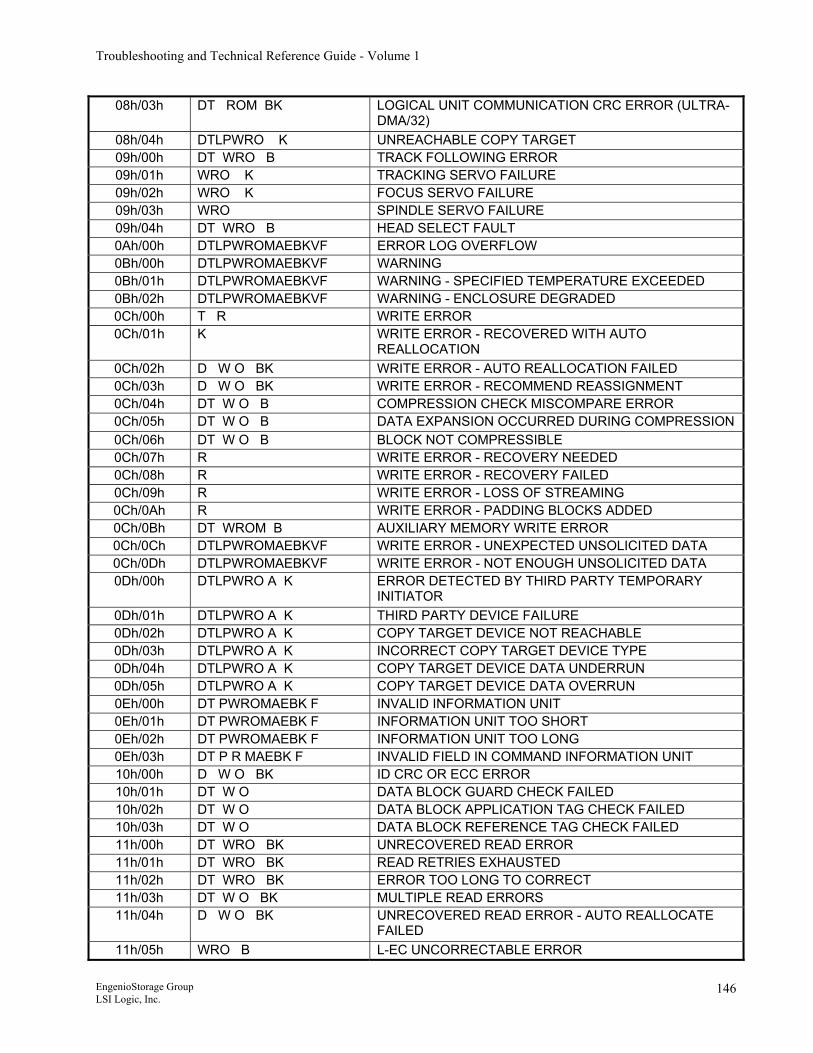
Troubleshooting and Technical Reference Guide - Volume 1
08h/03h DT ROM BK LOGICAL UNIT COMMUNICATION CRC ERROR (ULTRA-DMA/32)
08h/04h DTLPWRO K UNREACHABLE COPY TARGET 09h/00h DT WRO B TRACK FOLLOWING ERROR 09h/01h WRO K TRACKING SERVO FAILURE 09h/02h WRO K FOCUS SERVO FAILURE 09h/03h WRO SPINDLE SERVO FAILURE 09h/04h DT WRO B HEAD SELECT FAULT 0Ah/00h DTLPWROMAEBKVF ERROR LOG OVERFLOW 0Bh/00h DTLPWROMAEBKVF WARNING 0Bh/01h DTLPWROMAEBKVF WARNING - SPECIFIED TEMPERATURE EXCEEDED 0Bh/02h DTLPWROMAEBKVF WARNING - ENCLOSURE DEGRADED 0Ch/00h T R WRITE ERROR 0Ch/01h K WRITE ERROR - RECOVERED WITH AUTO
REALLOCATION 0Ch/02h D W O BK WRITE ERROR - AUTO REALLOCATION FAILED 0Ch/03h D W O BK WRITE ERROR - RECOMMEND REASSIGNMENT 0Ch/04h DT W O B COMPRESSION CHECK MISCOMPARE ERROR 0Ch/05h DT W O B DATA EXPANSION OCCURRED DURING COMPRESSION 0Ch/06h DT W O B BLOCK NOT COMPRESSIBLE 0Ch/07h R WRITE ERROR - RECOVERY NEEDED 0Ch/08h R WRITE ERROR - RECOVERY FAILED 0Ch/09h R WRITE ERROR - LOSS OF STREAMING 0Ch/0Ah R WRITE ERROR - PADDING BLOCKS ADDED 0Ch/0Bh DT WROM B AUXILIARY MEMORY WRITE ERROR 0Ch/0Ch DTLPWROMAEBKVF WRITE ERROR - UNEXPECTED UNSOLICITED DATA 0Ch/0Dh DTLPWROMAEBKVF WRITE ERROR - NOT ENOUGH UNSOLICITED DATA 0Dh/00h DTLPWRO A K ERROR DETECTED BY THIRD PARTY TEMPORARY
INITIATOR 0Dh/01h DTLPWRO A K THIRD PARTY DEVICE FAILURE 0Dh/02h DTLPWRO A K COPY TARGET DEVICE NOT REACHABLE 0Dh/03h DTLPWRO A K INCORRECT COPY TARGET DEVICE TYPE 0Dh/04h DTLPWRO A K COPY TARGET DEVICE DATA UNDERRUN 0Dh/05h DTLPWRO A K COPY TARGET DEVICE DATA OVERRUN 0Eh/00h DT PWROMAEBK F INVALID INFORMATION UNIT 0Eh/01h DT PWROMAEBK F INFORMATION UNIT TOO SHORT 0Eh/02h DT PWROMAEBK F INFORMATION UNIT TOO LONG 0Eh/03h DT P R MAEBK F INVALID FIELD IN COMMAND INFORMATION UNIT 10h/00h D W O BK ID CRC OR ECC ERROR 10h/01h DT W O DATA BLOCK GUARD CHECK FAILED 10h/02h DT W O DATA BLOCK APPLICATION TAG CHECK FAILED 10h/03h DT W O DATA BLOCK REFERENCE TAG CHECK FAILED 11h/00h DT WRO BK UNRECOVERED READ ERROR 11h/01h DT WRO BK READ RETRIES EXHAUSTED 11h/02h DT WRO BK ERROR TOO LONG TO CORRECT 11h/03h DT W O BK MULTIPLE READ ERRORS 11h/04h D W O BK UNRECOVERED READ ERROR - AUTO REALLOCATE
FAILED 11h/05h WRO B L-EC UNCORRECTABLE ERROR
EngenioStorage Group LSI Logic, Inc.
146
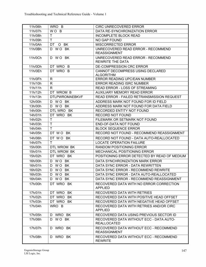
Troubleshooting and Technical Reference Guide - Volume 1
11h/06h WRO B CIRC UNRECOVERED ERROR 11h/07h W O B DATA RE-SYNCHRONIZATION ERROR 11h/08h T INCOMPLETE BLOCK READ 11h/09h T NO GAP FOUND 11h/0Ah DT O BK MISCORRECTED ERROR 11h/0Bh D W O BK UNRECOVERED READ ERROR - RECOMMEND
REASSIGNMENT 11h/0Ch D W O BK UNRECOVERED READ ERROR - RECOMMEND
REWRITE THE DATA 11h/0Dh DT WRO B DE-COMPRESSION CRC ERROR 11h/0Eh DT WRO B CANNOT DECOMPRESS USING DECLARED
ALGORITHM 11h/0Fh R ERROR READING UPC/EAN NUMBER 11h/10h R ERROR READING ISRC NUMBER 11h/11h R READ ERROR - LOSS OF STREAMING 11h/12h DT WROM B AUXILIARY MEMORY READ ERROR 11h/13h DTLPWROMAEBKVF READ ERROR - FAILED RETRANSMISSION REQUEST 12h/00h D W O BK ADDRESS MARK NOT FOUND FOR ID FIELD 13h/00h D W O BK ADDRESS MARK NOT FOUND FOR DATA FIELD 14h/00h DTL WRO BK RECORDED ENTITY NOT FOUND 14h/01h DT WRO BK RECORD NOT FOUND 14h/02h T FILEMARK OR SETMARK NOT FOUND 14h/03h T END-OF-DATA NOT FOUND 14h/04h T BLOCK SEQUENCE ERROR 14h/05h DT W O BK RECORD NOT FOUND - RECOMMEND REASSIGNMENT 14h/06h DT W O BK RECORD NOT FOUND - DATA AUTO-REALLOCATED 14h/07h T LOCATE OPERATION FAILURE 15h/00h DTL WROM BK RANDOM POSITIONING ERROR 15h/01h DTL WROM BK MECHANICAL POSITIONING ERROR 15h/02h DT WRO BK POSITIONING ERROR DETECTED BY READ OF MEDIUM 16h/00h D W O BK DATA SYNCHRONIZATION MARK ERROR 16h/01h D W O BK DATA SYNC ERROR - DATA REWRITTEN 16h/02h D W O BK DATA SYNC ERROR - RECOMMEND REWRITE 16h/03h D W O BK DATA SYNC ERROR - DATA AUTO-REALLOCATED 16h/04h D W O BK DATA SYNC ERROR - RECOMMEND REASSIGNMENT 17h/00h DT WRO BK RECOVERED DATA WITH NO ERROR CORRECTION
APPLIED 17h/01h DT WRO BK RECOVERED DATA WITH RETRIES 17h/02h DT WRO BK RECOVERED DATA WITH POSITIVE HEAD OFFSET 17h/03h DT WRO BK RECOVERED DATA WITH NEGATIVE HEAD OFFSET 17h/04h WRO B RECOVERED DATA WITH RETRIES AND/OR CIRC
APPLIED 17h/05h D WRO BK RECOVERED DATA USING PREVIOUS SECTOR ID 17h/06h D W O BK RECOVERED DATA WITHOUT ECC - DATA AUTO-
REALLOCATED 17h/07h D WRO BK RECOVERED DATA WITHOUT ECC - RECOMMEND
REASSIGNMENT 17h/08h D WRO BK RECOVERED DATA WITHOUT ECC - RECOMMEND
REWRITE
EngenioStorage Group LSI Logic, Inc.
147
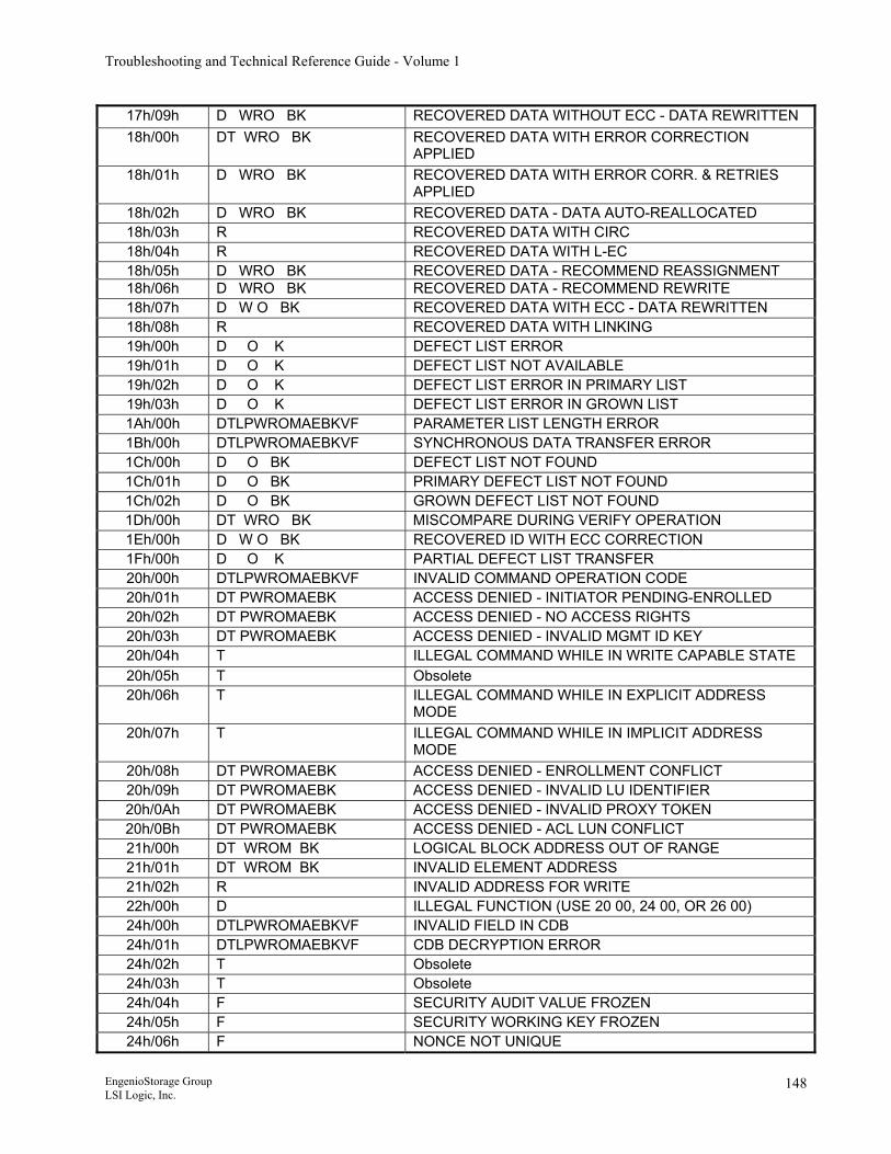
Troubleshooting and Technical Reference Guide - Volume 1
17h/09h D WRO BK RECOVERED DATA WITHOUT ECC - DATA REWRITTEN 18h/00h DT WRO BK RECOVERED DATA WITH ERROR CORRECTION
APPLIED 18h/01h D WRO BK RECOVERED DATA WITH ERROR CORR. & RETRIES
APPLIED 18h/02h D WRO BK RECOVERED DATA - DATA AUTO-REALLOCATED 18h/03h R RECOVERED DATA WITH CIRC 18h/04h R RECOVERED DATA WITH L-EC 18h/05h D WRO BK RECOVERED DATA - RECOMMEND REASSIGNMENT 18h/06h D WRO BK RECOVERED DATA - RECOMMEND REWRITE 18h/07h D W O BK RECOVERED DATA WITH ECC - DATA REWRITTEN 18h/08h R RECOVERED DATA WITH LINKING 19h/00h D O K DEFECT LIST ERROR 19h/01h D O K DEFECT LIST NOT AVAILABLE 19h/02h D O K DEFECT LIST ERROR IN PRIMARY LIST 19h/03h D O K DEFECT LIST ERROR IN GROWN LIST 1Ah/00h DTLPWROMAEBKVF PARAMETER LIST LENGTH ERROR 1Bh/00h DTLPWROMAEBKVF SYNCHRONOUS DATA TRANSFER ERROR 1Ch/00h D O BK DEFECT LIST NOT FOUND 1Ch/01h D O BK PRIMARY DEFECT LIST NOT FOUND 1Ch/02h D O BK GROWN DEFECT LIST NOT FOUND 1Dh/00h DT WRO BK MISCOMPARE DURING VERIFY OPERATION 1Eh/00h D W O BK RECOVERED ID WITH ECC CORRECTION 1Fh/00h D O K PARTIAL DEFECT LIST TRANSFER 20h/00h DTLPWROMAEBKVF INVALID COMMAND OPERATION CODE 20h/01h DT PWROMAEBK ACCESS DENIED - INITIATOR PENDING-ENROLLED 20h/02h DT PWROMAEBK ACCESS DENIED - NO ACCESS RIGHTS 20h/03h DT PWROMAEBK ACCESS DENIED - INVALID MGMT ID KEY 20h/04h T ILLEGAL COMMAND WHILE IN WRITE CAPABLE STATE 20h/05h T Obsolete 20h/06h T ILLEGAL COMMAND WHILE IN EXPLICIT ADDRESS
MODE 20h/07h T ILLEGAL COMMAND WHILE IN IMPLICIT ADDRESS
MODE 20h/08h DT PWROMAEBK ACCESS DENIED - ENROLLMENT CONFLICT 20h/09h DT PWROMAEBK ACCESS DENIED - INVALID LU IDENTIFIER 20h/0Ah DT PWROMAEBK ACCESS DENIED - INVALID PROXY TOKEN 20h/0Bh DT PWROMAEBK ACCESS DENIED - ACL LUN CONFLICT 21h/00h DT WROM BK LOGICAL BLOCK ADDRESS OUT OF RANGE 21h/01h DT WROM BK INVALID ELEMENT ADDRESS 21h/02h R INVALID ADDRESS FOR WRITE 22h/00h D ILLEGAL FUNCTION (USE 20 00, 24 00, OR 26 00) 24h/00h DTLPWROMAEBKVF INVALID FIELD IN CDB 24h/01h DTLPWROMAEBKVF CDB DECRYPTION ERROR 24h/02h T Obsolete 24h/03h T Obsolete 24h/04h F SECURITY AUDIT VALUE FROZEN 24h/05h F SECURITY WORKING KEY FROZEN 24h/06h F NONCE NOT UNIQUE
EngenioStorage Group LSI Logic, Inc.
148
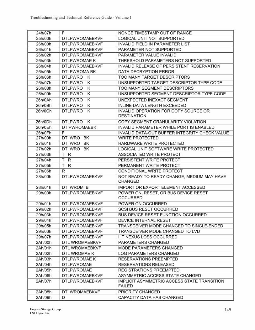
Troubleshooting and Technical Reference Guide - Volume 1
24h/07h F NONCE TIMESTAMP OUT OF RANGE 25h/00h DTLPWROMAEBKVF LOGICAL UNIT NOT SUPPORTED 26h/00h DTLPWROMAEBKVF INVALID FIELD IN PARAMETER LIST 26h/01h DTLPWROMAEBKVF PARAMETER NOT SUPPORTED 26h/02h DTLPWROMAEBKVF PARAMETER VALUE INVALID 26h/03h DTLPWROMAE K THRESHOLD PARAMETERS NOT SUPPORTED 26h/04h DTLPWROMAEBKVF INVALID RELEASE OF PERSISTENT RESERVATION 26h/05h DTLPWROMA BK DATA DECRYPTION ERROR 26h/06h DTLPWRO K TOO MANY TARGET DESCRIPTORS 26h/07h DTLPWRO K UNSUPPORTED TARGET DESCRIPTOR TYPE CODE 26h/08h DTLPWRO K TOO MANY SEGMENT DESCRIPTORS 26h/09h DTLPWRO K UNSUPPORTED SEGMENT DESCRIPTOR TYPE CODE 26h/0Ah DTLPWRO K UNEXPECTED INEXACT SEGMENT 26h/0Bh DTLPWRO K INLINE DATA LENGTH EXCEEDED 26h/0Ch DTLPWRO K INVALID OPERATION FOR COPY SOURCE OR
DESTINATION 26h/0Dh DTLPWRO K COPY SEGMENT GRANULARITY VIOLATION 26h/0Eh DT PWROMAEBK INVALID PARAMETER WHILE PORT IS ENABLED 26h/0Fh F INVALID DATA-OUT BUFFER INTEGRITY CHECK VALUE 27h/00h DT WRO BK WRITE PROTECTED 27h/01h DT WRO BK HARDWARE WRITE PROTECTED 27h/02h DT WRO BK LOGICAL UNIT SOFTWARE WRITE PROTECTED 27h/03h T R ASSOCIATED WRITE PROTECT 27h/04h T R PERSISTENT WRITE PROTECT 27h/05h T R PERMANENT WRITE PROTECT 27h/06h R CONDITIONAL WRITE PROTECT 28h/00h DTLPWROMAEBKVF NOT READY TO READY CHANGE, MEDIUM MAY HAVE
CHANGED 28h/01h DT WROM B IMPORT OR EXPORT ELEMENT ACCESSED 29h/00h DTLPWROMAEBKVF POWER ON, RESET, OR BUS DEVICE RESET
OCCURRED 29h/01h DTLPWROMAEBKVF POWER ON OCCURRED 29h/02h DTLPWROMAEBKVF SCSI BUS RESET OCCURRED 29h/03h DTLPWROMAEBKVF BUS DEVICE RESET FUNCTION OCCURRED 29h/04h DTLPWROMAEBKVF DEVICE INTERNAL RESET 29h/05h DTLPWROMAEBKVF TRANSCEIVER MODE CHANGED TO SINGLE-ENDED 29h/06h DTLPWROMAEBKVF TRANSCEIVER MODE CHANGED TO LVD 29h/07h DTLPWROMAEBKVF I_T NEXUS LOSS OCCURRED 2Ah/00h DTL WROMAEBKVF PARAMETERS CHANGED 2Ah/01h DTL WROMAEBKVF MODE PARAMETERS CHANGED 2Ah/02h DTL WROMAE K LOG PARAMETERS CHANGED 2Ah/03h DTLPWROMAE K RESERVATIONS PREEMPTED 2Ah/04h DTLPWROMAE RESERVATIONS RELEASED 2Ah/05h DTLPWROMAE REGISTRATIONS PREEMPTED 2Ah/06h DTLPWROMAEBKVF ASYMMETRIC ACCESS STATE CHANGED 2Ah/07h DTLPWROMAEBKVF IMPLICIT ASYMMETRIC ACCESS STATE TRANSITION
FAILED 2Ah/08h DT WROMAEBKVF PRIORITY CHANGED 2Ah/09h D CAPACITY DATA HAS CHANGED
EngenioStorage Group LSI Logic, Inc.
149
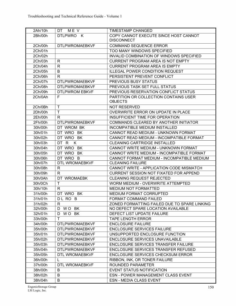
Troubleshooting and Technical Reference Guide - Volume 1
2Ah/10h DT M E V TIMESTAMP CHANGED 2Bh/00h DTLPWRO K COPY CANNOT EXECUTE SINCE HOST CANNOT
DISCONNECT 2Ch/00h DTLPWROMAEBKVF COMMAND SEQUENCE ERROR 2Ch/01h TOO MANY WINDOWS SPECIFIED 2Ch/02h INVALID COMBINATION OF WINDOWS SPECIFIED 2Ch/03h R CURRENT PROGRAM AREA IS NOT EMPTY 2Ch/04h R CURRENT PROGRAM AREA IS EMPTY 2Ch/05h B ILLEGAL POWER CONDITION REQUEST 2Ch/06h R PERSISTENT PREVENT CONFLICT 2Ch/07h DTLPWROMAEBKVF PREVIOUS BUSY STATUS 2Ch/08h DTLPWROMAEBKVF PREVIOUS TASK SET FULL STATUS 2Ch/09h DTLPWROM EBKVF PREVIOUS RESERVATION CONFLICT STATUS 2Ch/0Ah F PARTITION OR COLLECTION CONTAINS USER
OBJECTS 2Ch/0Bh T NOT RESERVED 2Dh/00h T OVERWRITE ERROR ON UPDATE IN PLACE 2Eh/00h R INSUFFICIENT TIME FOR OPERATION 2Fh/00h DTLPWROMAEBKVF COMMANDS CLEARED BY ANOTHER INITIATOR 30h/00h DT WROM BK INCOMPATIBLE MEDIUM INSTALLED 30h/01h DT WRO BK CANNOT READ MEDIUM - UNKNOWN FORMAT 30h/02h DT WRO BK CANNOT READ MEDIUM - INCOMPATIBLE FORMAT 30h/03h DT R K CLEANING CARTRIDGE INSTALLED 30h/04h DT WRO BK CANNOT WRITE MEDIUM - UNKNOWN FORMAT 30h/05h DT WRO BK CANNOT WRITE MEDIUM - INCOMPATIBLE FORMAT 30h/06h DT WRO B CANNOT FORMAT MEDIUM - INCOMPATIBLE MEDIUM 30h/07h DTL WROMAEBKVF CLEANING FAILURE 30h/08h R CANNOT WRITE - APPLICATION CODE MISMATCH 30h/09h R CURRENT SESSION NOT FIXATED FOR APPEND 30h/0Ah DT WROMAEBK CLEANING REQUEST REJECTED 30h/0Ch T WORM MEDIUM - OVERWRITE ATTEMPTED 30h/10h R MEDIUM NOT FORMATTED 31h/00h DT WRO BK MEDIUM FORMAT CORRUPTED 31h/01h D L RO B FORMAT COMMAND FAILED 31h/02h R ZONED FORMATTING FAILED DUE TO SPARE LINKING 32h/00h D W O BK NO DEFECT SPARE LOCATION AVAILABLE 32h/01h D W O BK DEFECT LIST UPDATE FAILURE 33h/00h T TAPE LENGTH ERROR 34h/00h DTLPWROMAEBKVF ENCLOSURE FAILURE 35h/00h DTLPWROMAEBKVF ENCLOSURE SERVICES FAILURE 35h/01h DTLPWROMAEBKVF UNSUPPORTED ENCLOSURE FUNCTION 35h/02h DTLPWROMAEBKVF ENCLOSURE SERVICES UNAVAILABLE 35h/03h DTLPWROMAEBKVF ENCLOSURE SERVICES TRANSFER FAILURE 35h/04h DTLPWROMAEBKVF ENCLOSURE SERVICES TRANSFER REFUSED 35h/05h DTL WROMAEBKVF ENCLOSURE SERVICES CHECKSUM ERROR 36h/00h L RIBBON, INK, OR TONER FAILURE 37h/00h DTL WROMAEBKVF ROUNDED PARAMETER 38h/00h B EVENT STATUS NOTIFICATION 38h/02h B ESN - POWER MANAGEMENT CLASS EVENT 38h/04h B ESN - MEDIA CLASS EVENT
EngenioStorage Group LSI Logic, Inc.
150
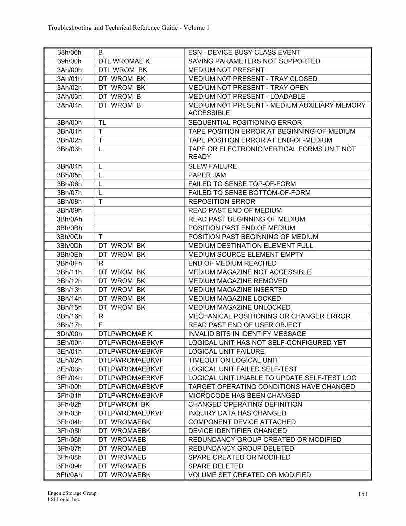
Troubleshooting and Technical Reference Guide - Volume 1
38h/06h B ESN - DEVICE BUSY CLASS EVENT 39h/00h DTL WROMAE K SAVING PARAMETERS NOT SUPPORTED 3Ah/00h DTL WROM BK MEDIUM NOT PRESENT 3Ah/01h DT WROM BK MEDIUM NOT PRESENT - TRAY CLOSED 3Ah/02h DT WROM BK MEDIUM NOT PRESENT - TRAY OPEN 3Ah/03h DT WROM B MEDIUM NOT PRESENT - LOADABLE 3Ah/04h DT WROM B MEDIUM NOT PRESENT - MEDIUM AUXILIARY MEMORY
ACCESSIBLE 3Bh/00h TL SEQUENTIAL POSITIONING ERROR 3Bh/01h T TAPE POSITION ERROR AT BEGINNING-OF-MEDIUM 3Bh/02h T TAPE POSITION ERROR AT END-OF-MEDIUM 3Bh/03h L TAPE OR ELECTRONIC VERTICAL FORMS UNIT NOT
READY 3Bh/04h L SLEW FAILURE 3Bh/05h L PAPER JAM 3Bh/06h L FAILED TO SENSE TOP-OF-FORM 3Bh/07h L FAILED TO SENSE BOTTOM-OF-FORM 3Bh/08h T REPOSITION ERROR 3Bh/09h READ PAST END OF MEDIUM 3Bh/0Ah READ PAST BEGINNING OF MEDIUM 3Bh/0Bh POSITION PAST END OF MEDIUM 3Bh/0Ch T POSITION PAST BEGINNING OF MEDIUM 3Bh/0Dh DT WROM BK MEDIUM DESTINATION ELEMENT FULL 3Bh/0Eh DT WROM BK MEDIUM SOURCE ELEMENT EMPTY 3Bh/0Fh R END OF MEDIUM REACHED 3Bh/11h DT WROM BK MEDIUM MAGAZINE NOT ACCESSIBLE 3Bh/12h DT WROM BK MEDIUM MAGAZINE REMOVED 3Bh/13h DT WROM BK MEDIUM MAGAZINE INSERTED 3Bh/14h DT WROM BK MEDIUM MAGAZINE LOCKED 3Bh/15h DT WROM BK MEDIUM MAGAZINE UNLOCKED 3Bh/16h R MECHANICAL POSITIONING OR CHANGER ERROR 3Bh/17h F READ PAST END OF USER OBJECT 3Dh/00h DTLPWROMAE K INVALID BITS IN IDENTIFY MESSAGE 3Eh/00h DTLPWROMAEBKVF LOGICAL UNIT HAS NOT SELF-CONFIGURED YET 3Eh/01h DTLPWROMAEBKVF LOGICAL UNIT FAILURE 3Eh/02h DTLPWROMAEBKVF TIMEOUT ON LOGICAL UNIT 3Eh/03h DTLPWROMAEBKVF LOGICAL UNIT FAILED SELF-TEST 3Eh/04h DTLPWROMAEBKVF LOGICAL UNIT UNABLE TO UPDATE SELF-TEST LOG 3Fh/00h DTLPWROMAEBKVF TARGET OPERATING CONDITIONS HAVE CHANGED 3Fh/01h DTLPWROMAEBKVF MICROCODE HAS BEEN CHANGED 3Fh/02h DTLPWROM BK CHANGED OPERATING DEFINITION 3Fh/03h DTLPWROMAEBKVF INQUIRY DATA HAS CHANGED 3Fh/04h DT WROMAEBK COMPONENT DEVICE ATTACHED 3Fh/05h DT WROMAEBK DEVICE IDENTIFIER CHANGED 3Fh/06h DT WROMAEB REDUNDANCY GROUP CREATED OR MODIFIED 3Fh/07h DT WROMAEB REDUNDANCY GROUP DELETED 3Fh/08h DT WROMAEB SPARE CREATED OR MODIFIED 3Fh/09h DT WROMAEB SPARE DELETED 3Fh/0Ah DT WROMAEBK VOLUME SET CREATED OR MODIFIED
EngenioStorage Group LSI Logic, Inc.
151
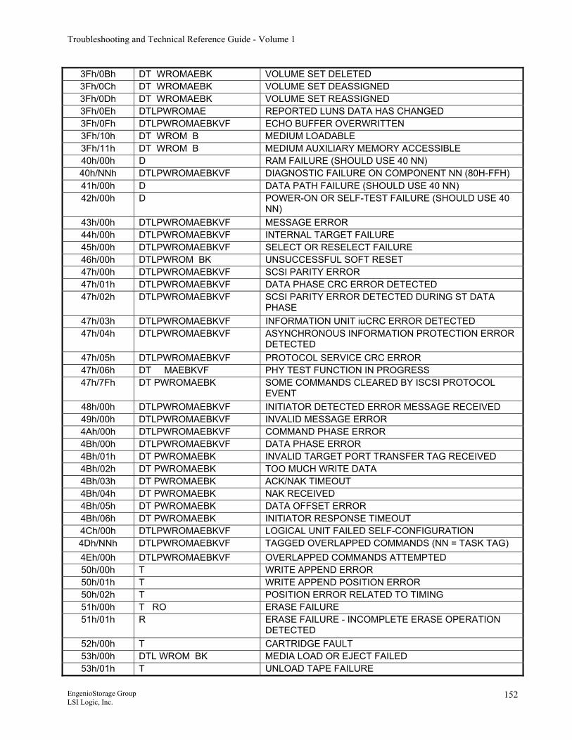
Troubleshooting and Technical Reference Guide - Volume 1
3Fh/0Bh DT WROMAEBK VOLUME SET DELETED 3Fh/0Ch DT WROMAEBK VOLUME SET DEASSIGNED 3Fh/0Dh DT WROMAEBK VOLUME SET REASSIGNED 3Fh/0Eh DTLPWROMAE REPORTED LUNS DATA HAS CHANGED 3Fh/0Fh DTLPWROMAEBKVF ECHO BUFFER OVERWRITTEN 3Fh/10h DT WROM B MEDIUM LOADABLE 3Fh/11h DT WROM B MEDIUM AUXILIARY MEMORY ACCESSIBLE 40h/00h D RAM FAILURE (SHOULD USE 40 NN) 40h/NNh DTLPWROMAEBKVF DIAGNOSTIC FAILURE ON COMPONENT NN (80H-FFH) 41h/00h D DATA PATH FAILURE (SHOULD USE 40 NN) 42h/00h D POWER-ON OR SELF-TEST FAILURE (SHOULD USE 40
NN) 43h/00h DTLPWROMAEBKVF MESSAGE ERROR 44h/00h DTLPWROMAEBKVF INTERNAL TARGET FAILURE 45h/00h DTLPWROMAEBKVF SELECT OR RESELECT FAILURE 46h/00h DTLPWROM BK UNSUCCESSFUL SOFT RESET 47h/00h DTLPWROMAEBKVF SCSI PARITY ERROR 47h/01h DTLPWROMAEBKVF DATA PHASE CRC ERROR DETECTED 47h/02h DTLPWROMAEBKVF SCSI PARITY ERROR DETECTED DURING ST DATA
PHASE 47h/03h DTLPWROMAEBKVF INFORMATION UNIT iuCRC ERROR DETECTED 47h/04h DTLPWROMAEBKVF ASYNCHRONOUS INFORMATION PROTECTION ERROR
DETECTED 47h/05h DTLPWROMAEBKVF PROTOCOL SERVICE CRC ERROR 47h/06h DT MAEBKVF PHY TEST FUNCTION IN PROGRESS 47h/7Fh DT PWROMAEBK SOME COMMANDS CLEARED BY ISCSI PROTOCOL
EVENT 48h/00h DTLPWROMAEBKVF INITIATOR DETECTED ERROR MESSAGE RECEIVED 49h/00h DTLPWROMAEBKVF INVALID MESSAGE ERROR 4Ah/00h DTLPWROMAEBKVF COMMAND PHASE ERROR 4Bh/00h DTLPWROMAEBKVF DATA PHASE ERROR 4Bh/01h DT PWROMAEBK INVALID TARGET PORT TRANSFER TAG RECEIVED 4Bh/02h DT PWROMAEBK TOO MUCH WRITE DATA 4Bh/03h DT PWROMAEBK ACK/NAK TIMEOUT 4Bh/04h DT PWROMAEBK NAK RECEIVED 4Bh/05h DT PWROMAEBK DATA OFFSET ERROR 4Bh/06h DT PWROMAEBK INITIATOR RESPONSE TIMEOUT 4Ch/00h DTLPWROMAEBKVF LOGICAL UNIT FAILED SELF-CONFIGURATION 4Dh/NNh DTLPWROMAEBKVF TAGGED OVERLAPPED COMMANDS (NN = TASK TAG) 4Eh/00h DTLPWROMAEBKVF OVERLAPPED COMMANDS ATTEMPTED 50h/00h T WRITE APPEND ERROR 50h/01h T WRITE APPEND POSITION ERROR 50h/02h T POSITION ERROR RELATED TO TIMING 51h/00h T RO ERASE FAILURE 51h/01h R ERASE FAILURE - INCOMPLETE ERASE OPERATION
DETECTED 52h/00h T CARTRIDGE FAULT 53h/00h DTL WROM BK MEDIA LOAD OR EJECT FAILED 53h/01h T UNLOAD TAPE FAILURE
EngenioStorage Group LSI Logic, Inc.
152
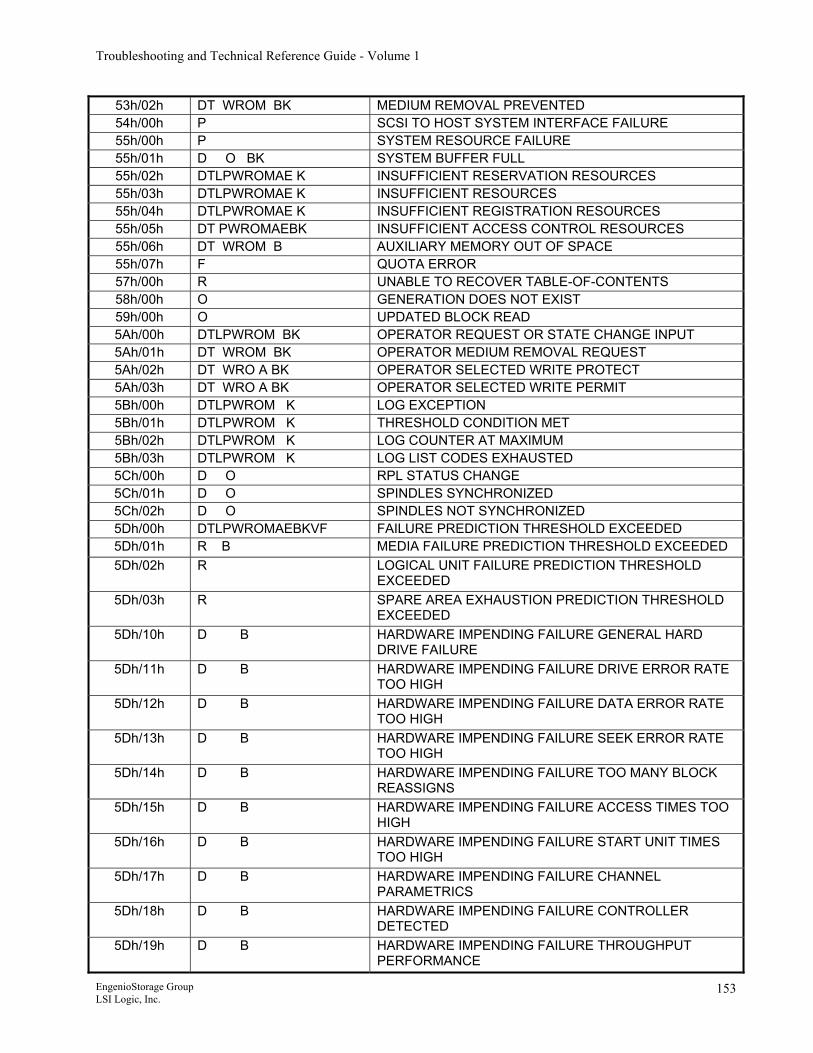
Troubleshooting and Technical Reference Guide - Volume 1
53h/02h DT WROM BK MEDIUM REMOVAL PREVENTED 54h/00h P SCSI TO HOST SYSTEM INTERFACE FAILURE 55h/00h P SYSTEM RESOURCE FAILURE 55h/01h D O BK SYSTEM BUFFER FULL 55h/02h DTLPWROMAE K INSUFFICIENT RESERVATION RESOURCES 55h/03h DTLPWROMAE K INSUFFICIENT RESOURCES 55h/04h DTLPWROMAE K INSUFFICIENT REGISTRATION RESOURCES 55h/05h DT PWROMAEBK INSUFFICIENT ACCESS CONTROL RESOURCES 55h/06h DT WROM B AUXILIARY MEMORY OUT OF SPACE 55h/07h F QUOTA ERROR 57h/00h R UNABLE TO RECOVER TABLE-OF-CONTENTS 58h/00h O GENERATION DOES NOT EXIST 59h/00h O UPDATED BLOCK READ 5Ah/00h DTLPWROM BK OPERATOR REQUEST OR STATE CHANGE INPUT 5Ah/01h DT WROM BK OPERATOR MEDIUM REMOVAL REQUEST 5Ah/02h DT WRO A BK OPERATOR SELECTED WRITE PROTECT 5Ah/03h DT WRO A BK OPERATOR SELECTED WRITE PERMIT 5Bh/00h DTLPWROM K LOG EXCEPTION 5Bh/01h DTLPWROM K THRESHOLD CONDITION MET 5Bh/02h DTLPWROM K LOG COUNTER AT MAXIMUM 5Bh/03h DTLPWROM K LOG LIST CODES EXHAUSTED 5Ch/00h D O RPL STATUS CHANGE 5Ch/01h D O SPINDLES SYNCHRONIZED 5Ch/02h D O SPINDLES NOT SYNCHRONIZED 5Dh/00h DTLPWROMAEBKVF FAILURE PREDICTION THRESHOLD EXCEEDED 5Dh/01h R B MEDIA FAILURE PREDICTION THRESHOLD EXCEEDED 5Dh/02h R LOGICAL UNIT FAILURE PREDICTION THRESHOLD
EXCEEDED 5Dh/03h R SPARE AREA EXHAUSTION PREDICTION THRESHOLD
EXCEEDED 5Dh/10h D B HARDWARE IMPENDING FAILURE GENERAL HARD
DRIVE FAILURE 5Dh/11h D B HARDWARE IMPENDING FAILURE DRIVE ERROR RATE
TOO HIGH 5Dh/12h D B HARDWARE IMPENDING FAILURE DATA ERROR RATE
TOO HIGH 5Dh/13h D B HARDWARE IMPENDING FAILURE SEEK ERROR RATE
TOO HIGH 5Dh/14h D B HARDWARE IMPENDING FAILURE TOO MANY BLOCK
REASSIGNS 5Dh/15h D B HARDWARE IMPENDING FAILURE ACCESS TIMES TOO
HIGH 5Dh/16h D B HARDWARE IMPENDING FAILURE START UNIT TIMES
TOO HIGH 5Dh/17h D B HARDWARE IMPENDING FAILURE CHANNEL
PARAMETRICS 5Dh/18h D B HARDWARE IMPENDING FAILURE CONTROLLER
DETECTED 5Dh/19h D B HARDWARE IMPENDING FAILURE THROUGHPUT
PERFORMANCE
EngenioStorage Group LSI Logic, Inc.
153
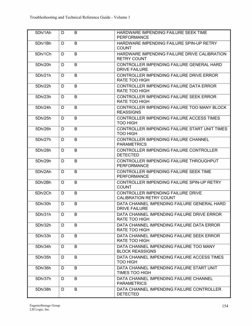
Troubleshooting and Technical Reference Guide - Volume 1
5Dh/1Ah D B HARDWARE IMPENDING FAILURE SEEK TIME PERFORMANCE
5Dh/1Bh D B HARDWARE IMPENDING FAILURE SPIN-UP RETRY COUNT
5Dh/1Ch D B HARDWARE IMPENDING FAILURE DRIVE CALIBRATION RETRY COUNT
5Dh/20h D B CONTROLLER IMPENDING FAILURE GENERAL HARD DRIVE FAILURE
5Dh/21h D B CONTROLLER IMPENDING FAILURE DRIVE ERROR RATE TOO HIGH
5Dh/22h D B CONTROLLER IMPENDING FAILURE DATA ERROR RATE TOO HIGH
5Dh/23h D B CONTROLLER IMPENDING FAILURE SEEK ERROR RATE TOO HIGH
5Dh/24h D B CONTROLLER IMPENDING FAILURE TOO MANY BLOCK REASSIGNS
5Dh/25h D B CONTROLLER IMPENDING FAILURE ACCESS TIMES TOO HIGH
5Dh/26h D B CONTROLLER IMPENDING FAILURE START UNIT TIMES TOO HIGH
5Dh/27h D B CONTROLLER IMPENDING FAILURE CHANNEL PARAMETRICS
5Dh/28h D B CONTROLLER IMPENDING FAILURE CONTROLLER DETECTED
5Dh/29h D B CONTROLLER IMPENDING FAILURE THROUGHPUT PERFORMANCE
5Dh/2Ah D B CONTROLLER IMPENDING FAILURE SEEK TIME PERFORMANCE
5Dh/2Bh D B CONTROLLER IMPENDING FAILURE SPIN-UP RETRY COUNT
5Dh/2Ch D B CONTROLLER IMPENDING FAILURE DRIVE CALIBRATION RETRY COUNT
5Dh/30h D B DATA CHANNEL IMPENDING FAILURE GENERAL HARD DRIVE FAILURE
5Dh/31h D B DATA CHANNEL IMPENDING FAILURE DRIVE ERROR RATE TOO HIGH
5Dh/32h D B DATA CHANNEL IMPENDING FAILURE DATA ERROR RATE TOO HIGH
5Dh/33h D B DATA CHANNEL IMPENDING FAILURE SEEK ERROR RATE TOO HIGH
5Dh/34h D B DATA CHANNEL IMPENDING FAILURE TOO MANY BLOCK REASSIGNS
5Dh/35h D B DATA CHANNEL IMPENDING FAILURE ACCESS TIMES TOO HIGH
5Dh/36h D B DATA CHANNEL IMPENDING FAILURE START UNIT TIMES TOO HIGH
5Dh/37h D B DATA CHANNEL IMPENDING FAILURE CHANNEL PARAMETRICS
5Dh/38h D B DATA CHANNEL IMPENDING FAILURE CONTROLLER DETECTED
EngenioStorage Group LSI Logic, Inc.
154
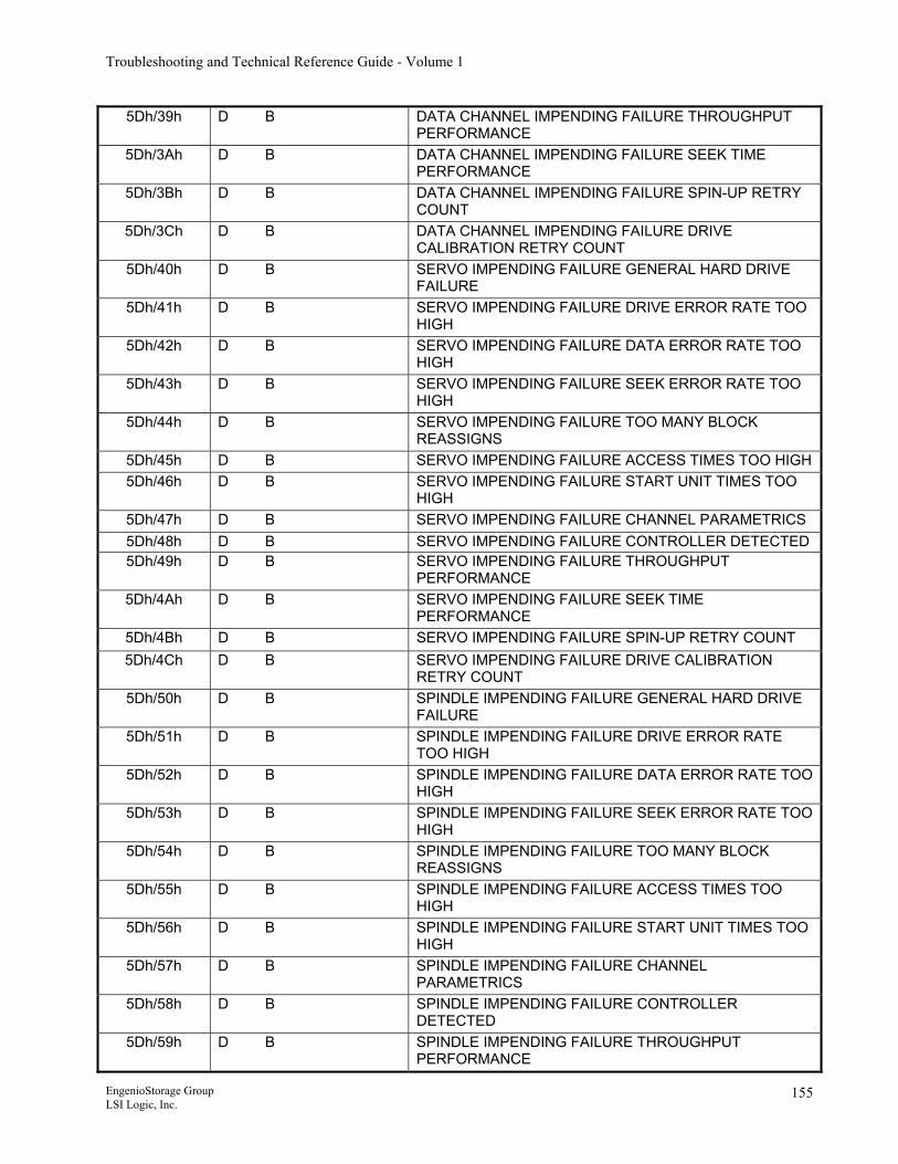
Troubleshooting and Technical Reference Guide - Volume 1
5Dh/39h D B DATA CHANNEL IMPENDING FAILURE THROUGHPUT PERFORMANCE
5Dh/3Ah D B DATA CHANNEL IMPENDING FAILURE SEEK TIME PERFORMANCE
5Dh/3Bh D B DATA CHANNEL IMPENDING FAILURE SPIN-UP RETRY COUNT
5Dh/3Ch D B DATA CHANNEL IMPENDING FAILURE DRIVE CALIBRATION RETRY COUNT
5Dh/40h D B SERVO IMPENDING FAILURE GENERAL HARD DRIVE FAILURE
5Dh/41h D B SERVO IMPENDING FAILURE DRIVE ERROR RATE TOO HIGH
5Dh/42h D B SERVO IMPENDING FAILURE DATA ERROR RATE TOO HIGH
5Dh/43h D B SERVO IMPENDING FAILURE SEEK ERROR RATE TOO HIGH
5Dh/44h D B SERVO IMPENDING FAILURE TOO MANY BLOCK REASSIGNS
5Dh/45h D B SERVO IMPENDING FAILURE ACCESS TIMES TOO HIGH 5Dh/46h D B SERVO IMPENDING FAILURE START UNIT TIMES TOO
HIGH 5Dh/47h D B SERVO IMPENDING FAILURE CHANNEL PARAMETRICS 5Dh/48h D B SERVO IMPENDING FAILURE CONTROLLER DETECTED 5Dh/49h D B SERVO IMPENDING FAILURE THROUGHPUT
PERFORMANCE 5Dh/4Ah D B SERVO IMPENDING FAILURE SEEK TIME
PERFORMANCE 5Dh/4Bh D B SERVO IMPENDING FAILURE SPIN-UP RETRY COUNT 5Dh/4Ch D B SERVO IMPENDING FAILURE DRIVE CALIBRATION
RETRY COUNT 5Dh/50h D B SPINDLE IMPENDING FAILURE GENERAL HARD DRIVE
FAILURE 5Dh/51h D B SPINDLE IMPENDING FAILURE DRIVE ERROR RATE
TOO HIGH 5Dh/52h D B SPINDLE IMPENDING FAILURE DATA ERROR RATE TOO
HIGH 5Dh/53h D B SPINDLE IMPENDING FAILURE SEEK ERROR RATE TOO
HIGH 5Dh/54h D B SPINDLE IMPENDING FAILURE TOO MANY BLOCK
REASSIGNS 5Dh/55h D B SPINDLE IMPENDING FAILURE ACCESS TIMES TOO
HIGH 5Dh/56h D B SPINDLE IMPENDING FAILURE START UNIT TIMES TOO
HIGH 5Dh/57h D B SPINDLE IMPENDING FAILURE CHANNEL
PARAMETRICS 5Dh/58h D B SPINDLE IMPENDING FAILURE CONTROLLER
DETECTED 5Dh/59h D B SPINDLE IMPENDING FAILURE THROUGHPUT
PERFORMANCE
EngenioStorage Group LSI Logic, Inc.
155
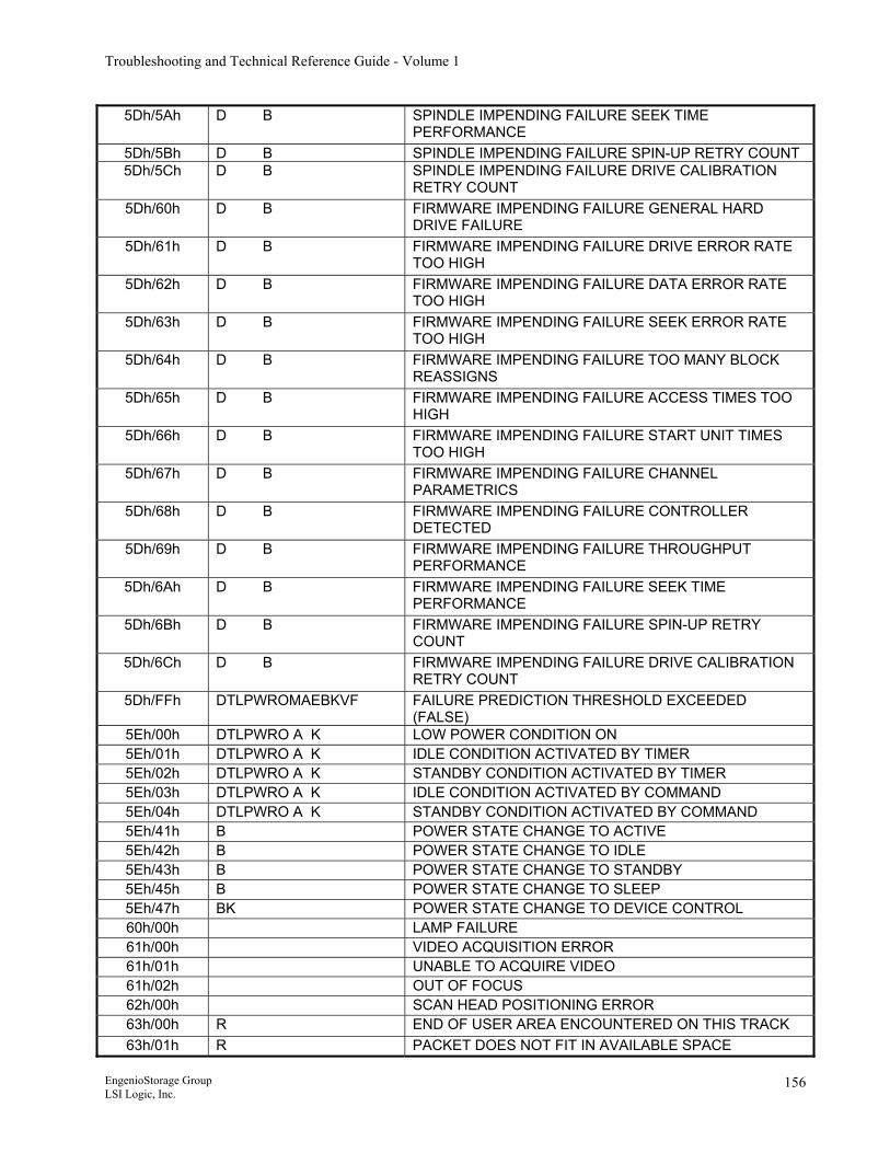
Troubleshooting and Technical Reference Guide - Volume 1
5Dh/5Ah D B SPINDLE IMPENDING FAILURE SEEK TIME PERFORMANCE
5Dh/5Bh D B SPINDLE IMPENDING FAILURE SPIN-UP RETRY COUNT 5Dh/5Ch D B SPINDLE IMPENDING FAILURE DRIVE CALIBRATION
RETRY COUNT 5Dh/60h D B FIRMWARE IMPENDING FAILURE GENERAL HARD
DRIVE FAILURE 5Dh/61h D B FIRMWARE IMPENDING FAILURE DRIVE ERROR RATE
TOO HIGH 5Dh/62h D B FIRMWARE IMPENDING FAILURE DATA ERROR RATE
TOO HIGH 5Dh/63h D B FIRMWARE IMPENDING FAILURE SEEK ERROR RATE
TOO HIGH 5Dh/64h D B FIRMWARE IMPENDING FAILURE TOO MANY BLOCK
REASSIGNS 5Dh/65h D B FIRMWARE IMPENDING FAILURE ACCESS TIMES TOO
HIGH 5Dh/66h D B FIRMWARE IMPENDING FAILURE START UNIT TIMES
TOO HIGH 5Dh/67h D B FIRMWARE IMPENDING FAILURE CHANNEL
PARAMETRICS 5Dh/68h D B FIRMWARE IMPENDING FAILURE CONTROLLER
DETECTED 5Dh/69h D B FIRMWARE IMPENDING FAILURE THROUGHPUT
PERFORMANCE 5Dh/6Ah D B FIRMWARE IMPENDING FAILURE SEEK TIME
PERFORMANCE 5Dh/6Bh D B FIRMWARE IMPENDING FAILURE SPIN-UP RETRY
COUNT 5Dh/6Ch D B FIRMWARE IMPENDING FAILURE DRIVE CALIBRATION
RETRY COUNT 5Dh/FFh DTLPWROMAEBKVF FAILURE PREDICTION THRESHOLD EXCEEDED
(FALSE) 5Eh/00h DTLPWRO A K LOW POWER CONDITION ON 5Eh/01h DTLPWRO A K IDLE CONDITION ACTIVATED BY TIMER 5Eh/02h DTLPWRO A K STANDBY CONDITION ACTIVATED BY TIMER 5Eh/03h DTLPWRO A K IDLE CONDITION ACTIVATED BY COMMAND 5Eh/04h DTLPWRO A K STANDBY CONDITION ACTIVATED BY COMMAND 5Eh/41h B POWER STATE CHANGE TO ACTIVE 5Eh/42h B POWER STATE CHANGE TO IDLE 5Eh/43h B POWER STATE CHANGE TO STANDBY 5Eh/45h B POWER STATE CHANGE TO SLEEP 5Eh/47h BK POWER STATE CHANGE TO DEVICE CONTROL 60h/00h LAMP FAILURE 61h/00h VIDEO ACQUISITION ERROR 61h/01h UNABLE TO ACQUIRE VIDEO 61h/02h OUT OF FOCUS 62h/00h SCAN HEAD POSITIONING ERROR 63h/00h R END OF USER AREA ENCOUNTERED ON THIS TRACK 63h/01h R PACKET DOES NOT FIT IN AVAILABLE SPACE
EngenioStorage Group LSI Logic, Inc.
156
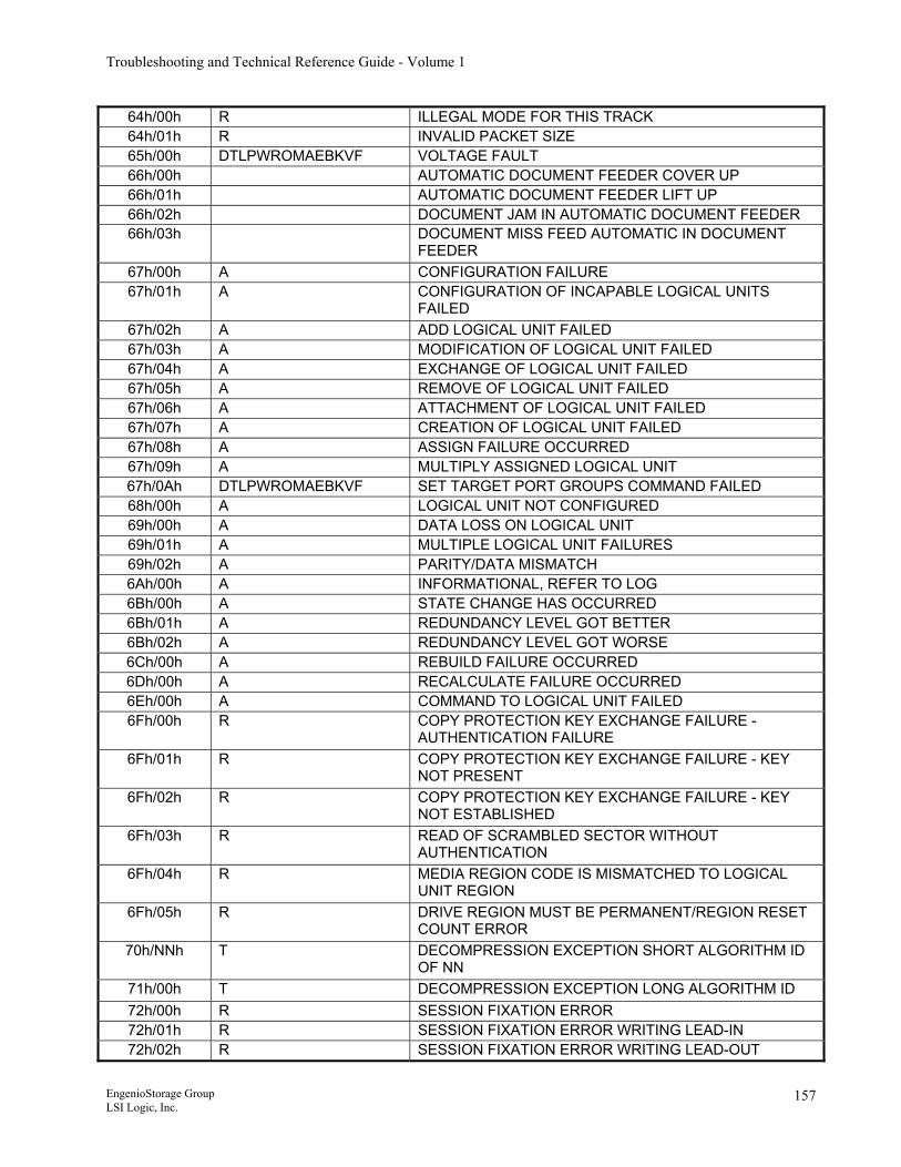
Troubleshooting and Technical Reference Guide - Volume 1
64h/00h R ILLEGAL MODE FOR THIS TRACK 64h/01h R INVALID PACKET SIZE 65h/00h DTLPWROMAEBKVF VOLTAGE FAULT 66h/00h AUTOMATIC DOCUMENT FEEDER COVER UP 66h/01h AUTOMATIC DOCUMENT FEEDER LIFT UP 66h/02h DOCUMENT JAM IN AUTOMATIC DOCUMENT FEEDER 66h/03h DOCUMENT MISS FEED AUTOMATIC IN DOCUMENT
FEEDER 67h/00h A CONFIGURATION FAILURE 67h/01h A CONFIGURATION OF INCAPABLE LOGICAL UNITS
FAILED 67h/02h A ADD LOGICAL UNIT FAILED 67h/03h A MODIFICATION OF LOGICAL UNIT FAILED 67h/04h A EXCHANGE OF LOGICAL UNIT FAILED 67h/05h A REMOVE OF LOGICAL UNIT FAILED 67h/06h A ATTACHMENT OF LOGICAL UNIT FAILED 67h/07h A CREATION OF LOGICAL UNIT FAILED 67h/08h A ASSIGN FAILURE OCCURRED 67h/09h A MULTIPLY ASSIGNED LOGICAL UNIT 67h/0Ah DTLPWROMAEBKVF SET TARGET PORT GROUPS COMMAND FAILED 68h/00h A LOGICAL UNIT NOT CONFIGURED 69h/00h A DATA LOSS ON LOGICAL UNIT 69h/01h A MULTIPLE LOGICAL UNIT FAILURES 69h/02h A PARITY/DATA MISMATCH 6Ah/00h A INFORMATIONAL, REFER TO LOG 6Bh/00h A STATE CHANGE HAS OCCURRED 6Bh/01h A REDUNDANCY LEVEL GOT BETTER 6Bh/02h A REDUNDANCY LEVEL GOT WORSE 6Ch/00h A REBUILD FAILURE OCCURRED 6Dh/00h A RECALCULATE FAILURE OCCURRED 6Eh/00h A COMMAND TO LOGICAL UNIT FAILED 6Fh/00h R COPY PROTECTION KEY EXCHANGE FAILURE -
AUTHENTICATION FAILURE 6Fh/01h R COPY PROTECTION KEY EXCHANGE FAILURE - KEY
NOT PRESENT 6Fh/02h R COPY PROTECTION KEY EXCHANGE FAILURE - KEY
NOT ESTABLISHED 6Fh/03h R READ OF SCRAMBLED SECTOR WITHOUT
AUTHENTICATION 6Fh/04h R MEDIA REGION CODE IS MISMATCHED TO LOGICAL
UNIT REGION 6Fh/05h R DRIVE REGION MUST BE PERMANENT/REGION RESET
COUNT ERROR 70h/NNh T DECOMPRESSION EXCEPTION SHORT ALGORITHM ID
OF NN 71h/00h T DECOMPRESSION EXCEPTION LONG ALGORITHM ID 72h/00h R SESSION FIXATION ERROR 72h/01h R SESSION FIXATION ERROR WRITING LEAD-IN 72h/02h R SESSION FIXATION ERROR WRITING LEAD-OUT
EngenioStorage Group LSI Logic, Inc.
157
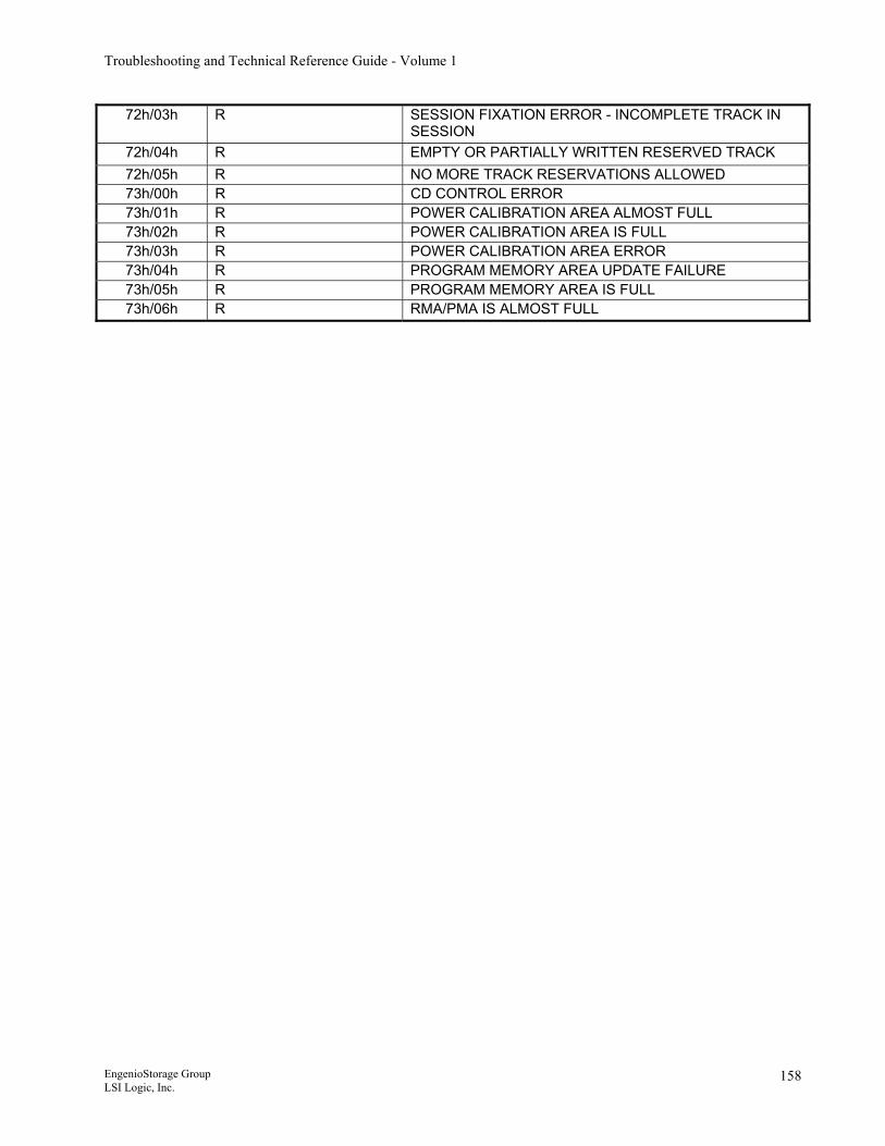
Troubleshooting and Technical Reference Guide - Volume 1
72h/03h R SESSION FIXATION ERROR - INCOMPLETE TRACK IN SESSION
72h/04h R EMPTY OR PARTIALLY WRITTEN RESERVED TRACK 72h/05h R NO MORE TRACK RESERVATIONS ALLOWED 73h/00h R CD CONTROL ERROR 73h/01h R POWER CALIBRATION AREA ALMOST FULL 73h/02h R POWER CALIBRATION AREA IS FULL 73h/03h R POWER CALIBRATION AREA ERROR 73h/04h R PROGRAM MEMORY AREA UPDATE FAILURE 73h/05h R PROGRAM MEMORY AREA IS FULL 73h/06h R RMA/PMA IS ALMOST FULL
EngenioStorage Group LSI Logic, Inc.
158
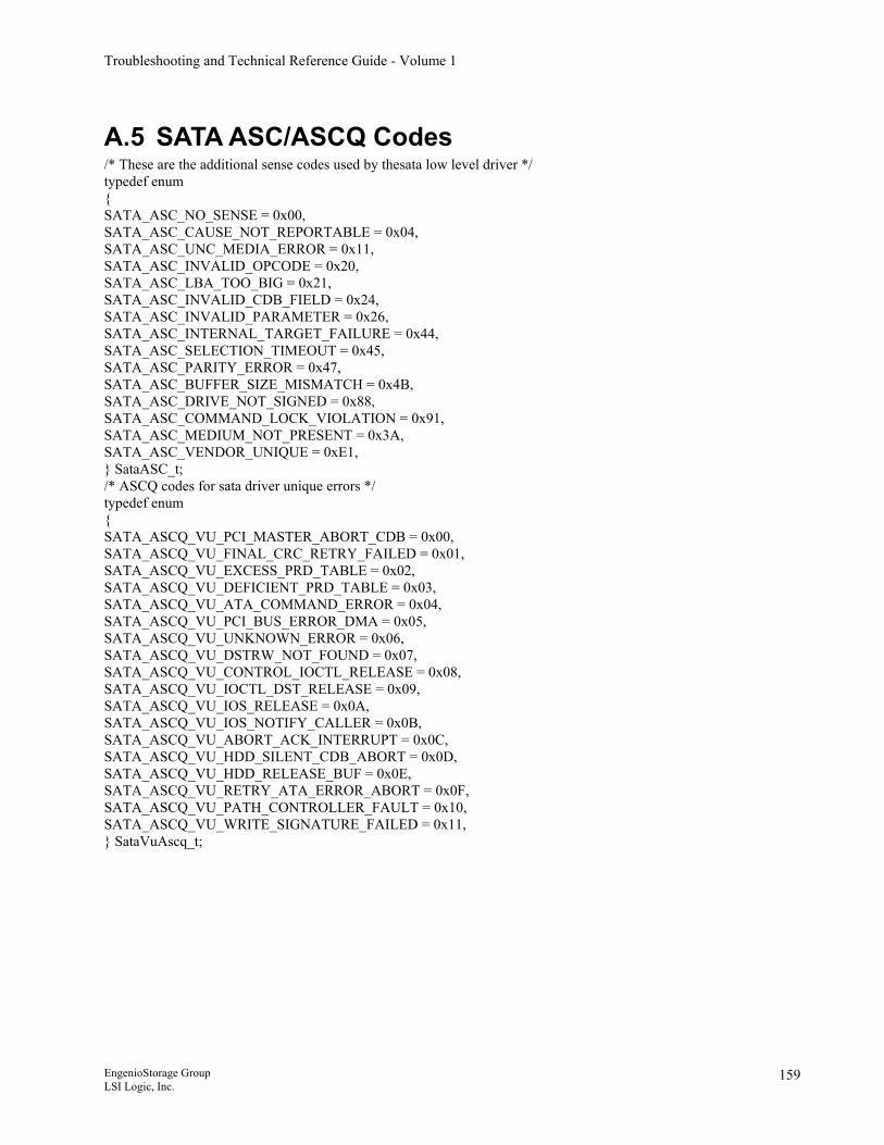
Troubleshooting and Technical Reference Guide - Volume 1
A.5 SATA ASC/ASCQ Codes /* These are the additional sense codes used by thesata low level driver */ typedef enum { SATA_ASC_NO_SENSE = 0x00, SATA_ASC_CAUSE_NOT_REPORTABLE = 0x04, SATA_ASC_UNC_MEDIA_ERROR = 0x11, SATA_ASC_INVALID_OPCODE = 0x20, SATA_ASC_LBA_TOO_BIG = 0x21, SATA_ASC_INVALID_CDB_FIELD = 0x24, SATA_ASC_INVALID_PARAMETER = 0x26, SATA_ASC_INTERNAL_TARGET_FAILURE = 0x44, SATA_ASC_SELECTION_TIMEOUT = 0x45, SATA_ASC_PARITY_ERROR = 0x47, SATA_ASC_BUFFER_SIZE_MISMATCH = 0x4B, SATA_ASC_DRIVE_NOT_SIGNED = 0x88, SATA_ASC_COMMAND_LOCK_VIOLATION = 0x91, SATA_ASC_MEDIUM_NOT_PRESENT = 0x3A, SATA_ASC_VENDOR_UNIQUE = 0xE1, } SataASC_t; /* ASCQ codes for sata driver unique errors */ typedef enum { SATA_ASCQ_VU_PCI_MASTER_ABORT_CDB = 0x00, SATA_ASCQ_VU_FINAL_CRC_RETRY_FAILED = 0x01, SATA_ASCQ_VU_EXCESS_PRD_TABLE = 0x02, SATA_ASCQ_VU_DEFICIENT_PRD_TABLE = 0x03, SATA_ASCQ_VU_ATA_COMMAND_ERROR = 0x04, SATA_ASCQ_VU_PCI_BUS_ERROR_DMA = 0x05, SATA_ASCQ_VU_UNKNOWN_ERROR = 0x06, SATA_ASCQ_VU_DSTRW_NOT_FOUND = 0x07, SATA_ASCQ_VU_CONTROL_IOCTL_RELEASE = 0x08, SATA_ASCQ_VU_IOCTL_DST_RELEASE = 0x09, SATA_ASCQ_VU_IOS_RELEASE = 0x0A, SATA_ASCQ_VU_IOS_NOTIFY_CALLER = 0x0B, SATA_ASCQ_VU_ABORT_ACK_INTERRUPT = 0x0C, SATA_ASCQ_VU_HDD_SILENT_CDB_ABORT = 0x0D, SATA_ASCQ_VU_HDD_RELEASE_BUF = 0x0E, SATA_ASCQ_VU_RETRY_ATA_ERROR_ABORT = 0x0F, SATA_ASCQ_VU_PATH_CONTROLLER_FAULT = 0x10, SATA_ASCQ_VU_WRITE_SIGNATURE_FAILED = 0x11, } SataVuAscq_t;
EngenioStorage Group LSI Logic, Inc.
159
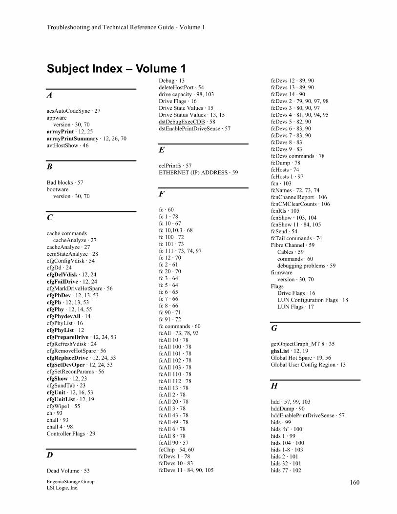
Troubleshooting and Technical Reference Guide - Volume 1
Subject Index – Volume 1
A
acsAutoCodeSync · 27 appware
version · 30, 70 arrayPrint · 12, 25 arrayPrintSummary · 12, 26, 70 avtHostShow · 46
B
Bad blocks · 57 bootware
version · 30, 70
C
cache commands cacheAnalyze · 27
cacheAnalyze · 27 ccmStateAnalyze · 28 cfgConfigVdisk · 54 cfgDd · 24 cfgDelVdisk · 12, 24 cfgFailDrive · 12, 24 cfgMarkDriveHotSpare · 56 cfgPbDev · 12, 13, 53 cfgPh · 12, 13, 53 cfgPhy · 12, 14, 55 cfgPhydevAll · 14 cfgPhyList · 16 cfgPhyList · 12 cfgPrepareDrive · 12, 24, 53 cfgRefreshVdisk · 24 cfgRemoveHotSpare · 56 cfgReplaceDrive · 12, 24, 53 cfgSetDevOper · 12, 24, 53 cfgSetReconParams · 56 cfgShow · 12, 23 cfgSundTab · 23 cfgUnit · 12, 16, 53 cfgUnitList · 12, 19 cfgWipe1 · 55 ch · 93 chall · 93 chall 4 · 98 Controller Flags · 29
D
Dead Volume · 53
Debug · 13 deleteHostPort · 54 drive capacity · 98, 103 Drive Flags · 16 Drive State Values · 15 Drive Status Values · 13, 15 dstDebugExecCDB · 58 dstEnablePrintDriveSense · 57
E
eelPrintfs · 57 ETHERNET (IP) ADDRESS · 59
F
fc · 60 fc 1 · 78 fc 10 · 67 fc 10,10,3 · 68 fc 100 · 72 fc 101 · 73 fc 111 · 73, 74, 97 fc 12 · 70 fc 2 · 61 fc 20 · 70 fc 3 · 64 fc 5 · 64 fc 6 · 65 fc 7 · 66 fc 8 · 66 fc 90 · 71 fc 91 · 72 fc commands · 60 fcAll · 73, 78, 93 fcAll 10 · 78 fcAll 100 · 78 fcAll 101 · 78 fcAll 102 · 78 fcAll 103 · 78 fcAll 110 · 78 fcAll 112 · 78 fcAll 13 · 78 fcAll 2 · 78 fcAll 20 · 78 fcAll 3 · 78 fcAll 43 · 78 fcAll 49 · 78 fcAll 6 · 78 fcAll 8 · 78 fcAll 90 · 57 fcChip · 54, 60 fcDevs 1 · 78 fcDevs 10 · 83 fcDevs 11 · 84, 90, 105
fcDevs 12 · 89, 90 fcDevs 13 · 89, 90 fcDevs 14 · 90 fcDevs 2 · 79, 90, 97, 98 fcDevs 3 · 80, 90, 97 fcDevs 4 · 81, 90, 94, 95 fcDevs 5 · 82, 90 fcDevs 6 · 83, 90 fcDevs 7 · 83, 90 fcDevs 8 · 83 fcDevs 9 · 83 fcDevs commands · 78 fcDump · 78 fcHosts · 74 fcHosts 1 · 97 fcn · 103 fcNames · 72, 73, 74 fcnChannelReport · 106 fcnCMClearCounts · 106 fcnRls · 105 fcnShow · 103, 104 fcnShow 11 · 84, 105 fcSend · 54 fcTail commands · 74 Fibre Channel · 59
Cables · 59 commands · 60 debugging problems · 59
firmware version · 30, 70
Flags Drive Flags · 16 LUN Configuration Flags · 18 LUN Flags · 17
G
getObjectGraph_MT 8 · 35 ghsList · 12, 19 Global Hot Spare · 19, 56 Global User Config Region · 13
H
hdd · 57, 99, 103 hddDump · 90 hddEnablePrintDriveSense · 57 hids · 99 hids ‘h’ · 100 hids 1 · 99 hids 104 · 100 hids 1-8 · 103 hids 2 · 101 hids 32 · 101 hids 77 · 102
EngenioStorage Group LSI Logic, Inc.
160
Troubleshooting and Technical Reference Guide - Volume 1
Host Port · 53
I
i · 13 I · 13 iditn · 95 iditnall · 95 iditnall 4 · 98 incrementCfgGenerationNumber · 24 ionHelp · 91 ionShow 11 · 95 ionShow 12 · 98 ionShow 99 · 98 ionShowInquiry · 97 iopPerfMonRestart · 71 isp · 24
L
lu · 94 luall · 94 luall 4 · 98 LUN Configuration Flags · 18 LUN Flags · 17 LUN State Values · 16
M
m · 57 Media Scan · 56 MEL · 53, 54 memoryShow · 29 memShow · 29 mhmPrintFredStatus · 45 mhmPrintPeanutStatus · 45 moduleList · 30, 70, 78 moduleShow · 32 mon · 56
N
netCfgSet · 46 netCfgShow · 46 NVSRAM · 55 NVSRAM FA Log Region · 13
P
printBatteryAge · 13
R
rdacMgrAltCtlFail · 12, 27 rdacMgrAltCtlReset · 27, 55 rdacMgrAltCtlResetRelease · 12,
27 rdacMgrSetModeActivePassive ·
12, 27 rdacMgrSetModeDualActive · 12,
27 reboot · 13 reboot controller · 27 resetDriveIdentify · 56 RLS · 84 rpaGetBatteryAge · 13
S
safeSysWipe · 13 sasHelp · 107 sasShowAllExpanders · 111 sasShowChannels · 108 sasShowDevices · 109 sasShowExpanders · 110 sasShowMiswires · 108 sasShowPhyErrStats · 108 setDriveIdentify · 56 shell commands
password · 11 starting the shell · 11
showEnclosures · 13 showMajorEvents · 54 SNAP
version · 30 SNAP version · 70 SPM · 58 spmClearDatabase · 58 spmShow · 32, 53 spmShowMaps · 34 ssmAudibleAlarm · 116 ssmHelp · 111 ssmIdentifyDrive · 116 ssmShow · 113 ssmShowEnclosures · 114 Storage Partition Management · 58 svlShow · 45 sysReboot · 13 sysWipe · 13 sysWipeZero · 13
T
tditn · 97 tditnall · 97 tditnall 4 · 98 Tracing · 57
V
vdAll · 12, 20 vdReconFixURE · 58 vdShow · 12, 20 VKI_EDIT_OPTIONS · 51 VKI_KMZALLOC · 57 VOLUME Flags · 29
W
Watchdog timer · 59 writeZerosFlag · 51
EngenioStorage Group LSI Logic, Inc.
161
Troubleshooting and Technical Reference Guide - Volume 1
Subject Index – Volume 2
A
arrayPrintSummary · 41
B
battery expired
during boot sequence · 6
C
ccmStateAnalyze · 41 cfgPh · 41 cfgPhy · 41 cfgShow · 41 cfgUnitList · 41 clearEnclosuresPage81 · 11 Clk Avg · 8 conAtt count · 8 Conn Attmpt · 8 controller
heartbeat · 5 led · 5
CRC Count · 8 CRCEC · 8 CRCErr count · 8
F
fcDump · 41
G
ghsList · 41
H
hddDump · 41 Held Off · 8
hldOff count · 8 Hub Mode · 9
I
ins count · 7 ionShow 99 · 41
L
LCC · 8 LED
start of day pattern · 5, 6 swapped controllers · 5
loop state · 8 Loop Up Cnt · 8 loopCy count · 8 loopUp count · 8 LS · 8 LUC · 8
M
moduleList · 41
N
Num LIP · 8
O
OPM · 8 OSEC · 8 OSErr count · 8
P
PCAC · 8 PCHOC · 8 PIC · 7 Port Mode · 8
Port Stat · 8 port state · 7 Port util · 8 PS · 7 PUP · 8
R
relFrq count · 8 RFDEA · 8 RM Log · 45, 46
S
Segmented Mode · 9 Serial Port · 41 sfpTreeModeMap · 7 showEnclosuresPage81 · 10, 14, 15 SOC Num · 8 SOC Port · 8 socClearSYMbolErrorStats · 11 socInHubMod · 7 socShow · 11, 13 String Mode · 9
T
Tree Mode · 9 tt sodMain · 41 tt tRAID · 41
U
Util Perc · 8
V
vdAll · 41 vdShow · 41
EngenioStorage Group LSI Logic, Inc.
162