Embed Size (px)
Citation preview

TAGpower Long Range Ridel5000 Reader/Encoder
Technical Manual
Cod.: 120.0011.1 Rev.: 0
July, 2003
TAGnology RFID GmbH | Grazer Vorstadt 142 | 8570 Voitsberg | AUSTRIA
phone: +43 (0)3142/28 9 28-10 | fax: +43 (0)3142/28 9 28-20 | [email protected] | www.tagnology.com

120.0011.1 0 Pag: 2
Indice General
1.- INTRODUCTION .................................................................................................................................. 4
1.1.- OVERVIEW ............................................................................................................................... 5
1.2.- SYSTEM DESCRIPTION ........................................................................................................... 6
1.3.- RIDEL5000 KEY FEATURES ..................................................................................................... 7
1.4.- RIDEL5000 VIEWS .................................................................................................................... 8
1.5.- SUPPLIED ELEMENTS ............................................................................................................. 9
1.6.- NON SUPPLIED ACCESORIES ................................................................................................ 9
2.-FUNCTIONAL DESCRIPTION............................................................................................................... 10
2.1.- RIDEL5000 BLOCK DIAGRAM................................................................................................... 11
2.2.- EXTERNAL CONNECTION ......................................................................................................... 13
2.3.- INTERFACES/INDICATOR DESCRIPTION ................................................................................. 14
2.3.1.- FRONT PANNEL CONNECTORS........................................................................................ 14
2.3.2.- REAR CONNECTOR AND INDICATORS ........................................................................... 14
2.3.3- INPUT/OUTPUT CIRCUIT .................................................................................................. 15
2.3.4.- OUTPUT CIRCUITS........................................................................................................... 15
3.-COMMAND SET .................................................................................................................................. 16
3.1.- PC-RIDEL5000 PROTOCOL....................................................................................................... 17
3.1.1.- SERIAL PROTOCOL ........................................................................................................ 17
3.1.1.1.- CHARACTER DEFINITIONS ........................................................................ 173.1.1.2.- PROTOCOL DESCRIPTION ........................................................................ 17
3.1.1.2.1.- COMMAND SEQUENCE ............................................................................ 183.1.1.2.2.- RESPONSE SEQUENCE ........................................................................... 18
3.1.1.3.- DATA BLOCK FORMATS ............................................................................ 183.1.1.3.1.- HOSTÞRIDEL5000 (COMMAND) ................................................................ 183.1.1.3.2.- RIDEL5000ÞHOST (RESPONSE) ............................................................... 193.1.1.3.3.- DESCRIPTION OF THE DATA BLOCK ........................................................ 19
3.2.- RIDEL5000 FUNCTIONS ............................................................................................................ 21
3.2.1.- SURVEY .......................................................................................................................... 21
3.2.1.1.- LOW LEVEL FUNCTIONS .......................................................................... 213.2.1.2.- TABLE OF STATUS VALUES ...................................................................... 22
3.2.2.- RIDEL5000 FUNCTIONS ................................................................................................... 23
3.2.2.1.- ANTICOLLISION/SELECT ........................................................................... 243.2.2.2.- READ ......................................................................................................... 253.2.2.3.- READ UNSELECTED ................................................................................. 263.2.2.4.- WRITE ........................................................................................................ 273.2.2.5.- HALT ........................................................................................................... 283.2.2.6.- RESET QUIET BIT ...................................................................................... 293.2.2.7.- EAS FUNCTION .......................................................................................... 29
3.3.- RIDEL5000 COMMANDS .......................................................................................................... 30
3.3.1.- RIDEL5000 CONFIGURATION COMMANDS .................................................................... 30
3.3.2.- RIDEL5000 STATE COMMANDS ..................................................................................... 30
3.3.3.- EEPROM INICIALIZATION ADDRESSES ............................................................................ 31
3.4.- TAG-WORLD PROTOCOL .......................................................................................................... 32

120.0011.1 0 Pag: 3
3.4.1.- CONTINOUS READ ............................................................................................... 323.4.2.- READ 323.4.3.- WRITE ................................................................................................................... 323.4.4.- VERSION .............................................................................................................. 32
3.5.- OPERATING MODES ................................................................................................................. 33
3.6.- INIZIALIZATION VARIABLES ....................................................................................................... 34
3.7.- DEFAULT VALUES ..................................................................................................................... 36
4.-TECHNICAL SPECIFICATION .............................................................................................................. 37
4.1.- ELECTRICAL SPECIFICATIONS ................................................................................................ 38
4.1.1.- RADIO .............................................................................................................................. 38
4.1.2.- COMMUNICATION ............................................................................................................ 38
4.1.3.- I/O PORTS ....................................................................................................................... 38
4.1.4.- POWER SUPPLY ............................................................................................................. 38
4.1.5.- ENVIROMENTAL .............................................................................................................. 38
4.1.6.- CE MARKING ................................................................................................................... 38
4.2.- PHISICAL DIMENSIONS ............................................................................................................ 39
5.-INSTALLATION ..................................................................................................................................... 40
5.1- CONTENTS AND UNPACKING .................................................................................................. 41
5.2.- STORAGE ................................................................................................................................. 41
5.3.- INSTALATION............................................................................................................................. 42
5.3.1.- REQUIRED ELEMENTS ................................................................................................... 42
5.3.2.- POWER SUPPLY/POWER CONSUMPTION .................................................................... 42
5.3.3.- OVERVOLTAGE/REVERSE POLARITY ........................................................................... 42
5.3.4.- ANTENNA......................................................................................................................... 42
5.3.5.- MECHANICAL CONSIDERATIONS ................................................................................... 43
5.3.5.- COMMUNICATION AND I/OCABLES ................................................................................ 44
5.3.6.- STARTUP PROCEDURE .................................................................................................. 44
5.4.- CABLE CONNECTION EXAMPLES ........................................................................................... 45
6.-TROUBLESHOOTING .......................................................................................................................... 46
6.1.- TEST PROCEDURE .................................................................................................................. 47
6.2.- PRELIMINAR TESTS ................................................................................................................. 47
6.3.- POWER ON .............................................................................................................................. 47
6.4.- RF AND COMMUNICATION MEASUREMENTS......................................................................... 48
6.5.- LABEL READING TEST ............................................................................................................. 48

120.0011.1 0 Pag: 4
1.- INTRODUCTION

120.0011.1 0 Pag: 5
1.1.- OVERVIEW
This chapter provides general information of the RIDEL5000 I-CODE reader-encoder, and associated equipment.
I-CODE protocol is a recent development in the field of Radio-Frequency identification (RFID). It is based in anew chip developed and manufactured by Philips Semiconductors, inside the Albatros european research program. Itprovides a low cost and high performance solution to any application requiring long-range reading and encoding ofinformation in one or several tags («smart labels») in the working field of one reader-encoder.
The I-CODE smart label includes one I-CODE chip and one antenna. It is powered by means of theelectromagnetic field generated by the reader/encoder, and in this situation, it establishes a communication link withthe unit. It is possible then, to detect, read or write the chip whithout any phisical or visual contact. The I-CODEprotocol incorporates an anti-collision feature, making it possible to simultaneously read and encode several labels inthe range of the antenna.
Tha label incorporates an unique factory-written electronic code, and a non-volatil memory area where it ispossible to store information. It can be writen up to 100.000 times.It has also an EAS (electronic article surveillance)software activated and deactivated feature.
The whole system operates at the normalized frequency of 13.56MHz.
There are many possible applications for this kind of systems, access control, logistics, retail, point of saleunits, manufacturing process control, ...
In POS or retail applications, the systems combines the anti-thief capability (EAS), and the product identification,incorporating in one system the benefits of the bar-code marking and the EAS tag anti-thief system.
In logistics applications, the block memory estructure makes the I-CODE smart label the best choice for thelogistic control of products. Also the multiple write capability, makes it ideal in an application where several users orstatements in a company have to deal with the same product. It is possible to add product information in every stagein the manufacturing or handling of the product or set or products.
In the manufacturing control process, its anti-collision feature makes it possible to read or write information inseveral parts included in the same set, individually, or as a whole, or even in a label fixed in the container. Thetrazability in the manufacturing process can be achieved by writing al the relevant data in the tag in every step of theprocess.

120.0011.1 0 Pag: 6
1.2.- SYSTEM DESCRIPTION
The following figure depicts the block diagram of a minimum I-CODE system including the RIDEL5000 longrange reader/encoder and the ANTMR5000 antenna.
RIDEL5000Reader/encoder
ANTMR5000Antenna
SmartLabel
PC Windows
The antenna is used to generate the electromagnetic field needed for the excitation of the transponder chip,and to receive the response of the label. Its proper design is very important to the functionality of the whole system.Many factors have to be considered in the design of the antenna:
• Required operating range
• Length and height of the operating field
• 2D or 3D geometry
• Background material
There are many standard or custom solutions for the antenna. In the picture the ANTMR5000 (a loop antennafor up to 80cm reading/encoding) has been depicted.
The RIDEL5000 is the RF transceiver needed to generate the neccesary RF transmitted power, to activate thelabel and to communicate with it, and to detect and process the tiny received signal from the I-CODE label. It alsosupports all the communications protocols with the controlling computer.
There is also one computer needed to run the control application (it is possible to configura the RIDEL5000 ina stand-alone mode). This applications provides the user interface to control the unit. The RIDEL5000 providescomplete information (reading-encoding process, EAS, calibration parameters, real time measurements of temperature,SWR, transmitted power, state of the antenna, ...) through its serial port. It is possible, then, to develope the completePC application according to the users requirements.
Support libraries have been developed to help system integrators or software developers to generate completehigh-level applications.
The I-CODE labels are designed in accordance with the system requirements. There are some standardformats, and it is possible to develope special sizes or materials for special applications. They are composed of a I-CODE chip, an antenna, and a material support.
The I-CODE chip is supplied by several manufacturers. It supports the label «intelligence», and includes themicroprocessor, memory, receiver, transmitter, and power supply systems.
The smart label antenna adopts many different forms and sizes, as required by the application. The designprocess is usually carried out by the label manufacturer, from the user specifications to the definition of the antennacharacteristics, the support material, and the final encapsulant.ç

120.0011.1 0 Pag: 7
1.3.- RIDEL5000 KEY FEATURES
This section details the key features of the RIDEL5000 long range I-CODE reader-encoder.
! Supports all I-CODE features
" Anti collision
" Contactless reading and encoding
" EAS detection, activation, deactivation
! 1.2m reading distance (with adequate antenna)
! Group / individual label selection
! Complete self-calibration and adjustment under microprocessor support
! Real time measurements of all the relevant working information
" Transmitted Power
" SWR
" Temperature
! Real time control of relevant working parameters
" Input filter characteristics
" IF Gain
" Reception level
! Easy software maintainance. Firmware update capability (FLASH memory program)
! RS232 and RS485 communication ports
! 4 Input and 4 Output I/O port
" Opto isolated inputs
" Solid State 6A outputs
! PC Control throug software libraries supplied
! Compact and light design

120.0011.1 0 Pag: 8
1.4.- RIDEL5000 VIEWS
In the following figure,it is shown the RIDEL5000 upper-front view, where it is possible to see the fan ventilationslots.
In the second figure it is possible to see the front pannel with the manufacturer identification label, and the twocoaxial antenna connectors.
In the last figure it is shown the rear view of the unit, with the power supply connector, the RS232 port and theI/O and RS3485 port. There is also the «activity» and the power indicators.

120.0011.1 0 Pag: 9
1.5.- SUPPLIED ELEMENTS
The unit is supplied in a box, with the user manual, warranty and CE conformity declaration.
1.6.- NON SUPPLIED ACCESORIES
As non supplied accesories, we can menction:
• 24Vcc, 1.5A Power Supply.
WARNING.- To minimize risk of electric shock and warranty propper operation of the unit,the power supply should be certified by UL, VDE, CS. The adapter and the personal computerconnected to this product should also be certified. The CE conformity test for the unit hasbeen carried out with the ASTEC SA45-3109 power supply.
• RS232 cable (DB9 male to DB9 female)
• RS232 cable (DB9 male to DB25 female)
• I/O and RS485 cable (DB15 male)
• Loop Antenna (ANTMR5000 model)
• Door Antenna (ANTLR5000 model)
• I-CODE 5x5cm label
• Test software for RIDEL5000
• Library CD for Windows programming

120.0011.1 0 Pag: 10
2.- FUNCTIONAL DESCRIPTION

120.0011.1 0 Pag: 11
2.1.- RIDEL5000 BLOCK DIAGRAM
The RIDEL5000 block diagram is shown in the following figure..
Power
Power Supply
SK
03
Transmitter
13.56MHzOscillator
DigitalModulator
RF PowerAmplifier
Reflectometer
Receiver
Antenna Selector
Antenna Switch
SK04
SK05Input Filter
DemodulatorAmplifier
A/D Converter
Interfaces
RS232 RS485 4 I/O
Control
Microcontroller
SK
02
SK
01
SK
01
The main blocks or subsystems are:
• The receiver
• The transmitter
• The antenna selector
• The controller
• The I/O interface
• The power supply
The receiver is integrated and encapsulated in a shielded box, to improve its enviroment noise inmunityand its sensibility. It is composed of an input filter, a demodulator, a signal amplifier (all of them with microcontrolleradjustment), and an A/D converter to provide information to the microcontroller for measurement and self-calibration purposes.
The transmitter is composed of an oscillator, whose signal is sent to a digital modulator, and a poweramplifier with incorporated temperature controll. In the transmitter output there is a reflectometer included,giving continous information to the microcontoller about the transmitted power and the antenna electricalcaracteristics. It makes it possible to determine SWR and the antenna impedance phase and module.
There is an antenna selector installed between SK03 and SK04 connectors, to select between the one-antenna and two-antennas working modes. (See INSTALATION chapter).

120.0011.1 0 Pag: 12
The whole unit is controlled by means of a microcontroller. It controlls the whole radio system, the I-CODEcommunication protocol, the RS232 and RS485 protocols, and the I/O ports. Its key features are:
• Flash program space. It is possible to modify the internal software through a programming interfaceprovided in the SK02 connector, by means of a special cable and PC software. This makes itpossible to update the unit with new versions or different protocolos without even opening it.
• Adittional memory for stand-alone applications (storage of the read labels data).
• EEPROM for working parameters storage (communication baud rate, default transmitted power,...)
The external interface is is made out of a RS232 port for point to point conections, RS485 port for the paralellconection of several RIDEL5000 units, or other RS485 equipment.
The I/O port consist of 4 input opto-isolated channels, and 4 solid state 6A output channel. It is undermicrocontroller control, and it can be used to output an alarm signal, to detect movement through a volumetric sensor,...
The power supply subsystem generates all the internal voltages needed for the unit from the 24Vcc input powersource.

120.0011.1 0 Pag: 13
2.2.- EXTERNAL CONNECTION
The following figure shows the external interface diagram for the RIDEL5000 module.
TAGSmart Label
Antenna RIDEL5000
TX/RX
RS232
RS485
4 Input Channel
4 Output Channel
Power Supply+24Vcc 1.5A
SK02
SK01
SK01
SK01
SK03
The module can be connected to a computer through its RS232 port. It is possible to select different baud ratesup to 115000 bauds.
The RS485 port makes it possible to control several RIDEL5000 units connected to the same bus. The moduleaddress or access code is included in the internal EEPROM of the unit.
The communication protocol is described for both interfaces in the COMMAND SET chapter.
The RIDEL5000 also includes one 4-channel I/0 port (4 opto-isolate inputs and 4 high current (6A) solid stateoutputs).
The unit is powered with an external 24Vcc-1.5A power supply, connected to the SK03 port.
The unit has in its front pannel, two BNC antenna connectors, so it is possible to configure the RIDEL5000 inthe one-antenna or two-antennas (TX-RX) modes, by means of an internal switch (see chapter about INSTALLATION).

120.0011.1 0 Pag: 14
2.3.- INTERFACES/INDICATOR DESCRIPTION
2.3.1.- FRONT PANNEL CONNECTORS
In the module front pannel, there are two RF BNC connectors, intended to connect one or two antennas. Theimpedance for both input-outputs is 50ohm.
• SK04 Reception antenna (two antennas mode)
• SK05 Transmission antenna (two antennas mode)
• SK04 or SK05 Transmission/Reception antenna (in one antenna mode)
2.3.2.- REAR CONNECTOR AND INDICATORS
In the rear of the unit, we can found the following connectors.
SK01 RS485 Connector. Auxiliary and programming
1.- +24Vcc 8.- Output 32.- Opto-isolated input ground 9.- Ground3.- Programming 2 10.- Programming 14.- Input 4 11.- Input 15.- Input 3 12.- Input 26.- Output 1 13.- Output 27.- Output 4 14.- Bus RS485 (A),(+)
15.- Bus RS485 (B),(-)
SK02 RS232 Connector
2.- Data Output TXD 5.- Ground3.- Data Input RXD 7.- RESET
SK03 Power Supply
SK03.- Power Supply connector, + inner conductor, - external conductor
Indicators
D1.- Power indicatorD2.- Activity and state indicator
SK04 SK05
123123
123123
1 1
SK02 SK01SK03 D1
D2

120.0011.1 0 Pag: 15
2.3.3- INPUT/OUTPUT CIRCUIT
The RIDEL5000 module, has 4 I/O channels (4 INPUT and 4 OUTPUTS) in SK01. The figure shows the inputcircuit. The circuit is opto-isolated by means of a opto-coupler whose input presents a series limiting resistor. Theinput circuit ground is common for the 4 channels, and is isolated from the general equipment ground.
The value of the input resistor is calculated to provide 10mA of input current when a 24Vcc voltage is applied tothe input terminal.
RIDEL5000
Optocoupler
SK01-2
SK01-4,5,11,12
INPUT 1..410mA 24Vcc
2.3.4.- OUTPUT CIRCUITS
The RIDEL5000 module has 4 output channels, as shown in the following figure. They are located in SK01connector. They are designed with HEXFET N channel transistors, with low internal resistance, configured as open-drain output.
The maximum allowable voltage for any output is 30V. The maximum allowable current is 6.7A.
RIDEL5000
HEXFET
SK01-9
SK01-6,7,8,13
OUTPUT 1..4max. 6.7A 30Vcc

120.0011.1 0 Pag: 16
3.- COMMAND SET

120.0011.1 0 Pag: 17
3.1.- PC-RIDEL5000 PROTOCOL
In this chapter, the serial communication protocol between the host computer and the RIDEL5000 will bedescribed. It is based on the COLIBRI Reader Module Specification Rev. 2.0. from PHILIPS SEMICONDUCTORS.
3.1.1.- SERIAL PROTOCOL
For point to point communications, the RIDEL5000 incorporates a RS232 link with the controlling computer.The communication parameters are defined as follows:
• 8 Data Bits
• One Stop Bit
• No Parity bit
The communication speed is software configurable between 9600 and 115200 baud. The unit is factoryconfigured at 115200 baud.
3.1.1.1.- CHARACTER DEFINITIONS
Description Char Value
Start of text STX 02HexEnd of text ETX 03HexData link escape DLE 10HexNo acknowledge NAK 15Hex
3.1.1.2.- PROTOCOL DESCRIPTION
To start a communication, the transmitter (at the command sequence this is the host, at the responsesequence, this is the RIDEL5000) and the receiver (at the command sequence the RIDEL5000, at the responsesequence the host), must be ready. The transmitter starts with STX to stablish a data link.
If the receiver answers NAK (or nothing), the transmitter repeats to send STX. If this trial fails again athird (i.e. the last) STX is transmitted to the receiver. If no valid response (DLE) is returned from the receiver, anerror message is generated finally, and the transmitter stops to establish a data link.
If the receiver answers DLE within a specified period of time (0.5s), data can be transmitted.
If DLE appears within a data block, it is transmitted twice to distinguish it from the control characterDLE.
If the defined maximum character delay (0.5s) is exceeded during transmission of the data block, thereceiver returns to the idle state and waits for another STX to establish a new data link.
At the end of transmission of the data block the transmitter transmits DLE and then ETX (DLE inneccesary to distinguish a control character from a data byte).
If the receiver detects no error in the transmission (i.e. correct CRC), it answers DLE. If an error isdetected, the receiver sends NAK, then the transmitter tries to repeat the entire transmission (maximum twotimes). If this is not possible it stops sending data and generates an error message.

120.0011.1 0 Pag: 18
3.1.1.2.1.- COMMAND SEQUENCE
HOST (Transmitter) RIDEL 5000 (Receiver)
STX ⇒ Receiver Ready?
⇐ DLE DLE: Yes!
Data[0] ⇒ Start of data block transmission
..
Data[n] ⇒
DLE ⇒ Next: Control character
ETX ⇒ End of transmission
⇐ DLE/NAK DLE: No error
NAK: An error occurred
3.1.1.2.2.- RESPONSE SEQUENCE
HOST (Receiver) RIDEL 5000(Transmitter)
⇐ STX Receiver Ready?
DLE ⇒ DLE: Yes!
⇐ Data[0] Start of data block transmission
..
⇐ Data[n]
⇐ DLE Next->Control character
⇐ ETX End of transmission
DLE/NAK ⇒ DLE: No error
NAK: An error occurred
The time in wich the receiver has to transmit the control characters upon the transmitter’s request is 0.5s. Thisis also the allowed maximum delay time between two characters during the communication.
3.1.1.3.- DATA BLOCK FORMATS
3.1.1.3.1.- HOSTÞRIDEL5000 (COMMAND)
TxSeq Command Len(0) Len(1) CRC16(1)CRC16(0)Par(0) ... Par(Len-1)
Data(0) Data(1) Data(2) Data(3) Data(4) Data(Len+3) Data(Len+4) Data (Len+5)
TxSeq Sequence number of the command 1 byte
Command Command code 1 byte
Len Number of parameter bytes (low byte, high byte) 2 bytes
Par Parameter bytes of command Len bytes
CRC16 16 bit CRC (low byte, high byte) 2 bytes

120.0011.1 0 Pag: 19
3.1.1.3.2.- RIDEL5000ÞHOST (RESPONSE)
RxSeq Status Len(0) Len(1) CRC16(1)CRC16(0)Res(0) ... Res(Len-1)
Data(0) Data(1) Data(2) Data(3) Data(4) Data(Len+3) Data(Len+4) Data(Len+5)
RxSeq Sequence number of the response 1 byte
Status Status byte (serial communication Host-Ridel) 1 byte
Len Number of response bytes (low byte, high byte) 2 bytes
Par Response bytes Len bytes
CRC16 16 bit CRC (low byte, high byte) 2 bytes
3.1.1.3.3.- DESCRIPTION OF THE DATA BLOCK
• A sequence numbrer is generated from the host sent within the data block. After a correct command/response exchange, the host increases the sequence number at the next command. The RIDEL5000returns always the last received sequence number.
It is recommended that the host application verifies the equality of the sent and received sequencenumbers after every command/sequence exchange.
• If the value 10 Hex (DLE) is transmitted within a data block, it is transmitted twice in order todistinguish it from the control character DLE.
The additionally transmitted value 10 Hex is not counted in Len.
• If the value 10 Hex (DLE) is transmitted within a data block, it is transmitted twice in order todistinguish it from the control character DLE.
The additionally transmitted value 10 Hex is not counted in Len.
• The 16 bit cyclic redundancy check character (CCITT-CRC16) is calculated as described in thefollowing:

120.0011.1 0 Pag: 20
Generator Polynom: X16
+ X12
+ X5+ 1 ⇒ CRC_POLYNOM = 8048 Hex
Preset Value: ⇒ CRC_PRESET = FFFF Hex
Calculation algorithm (C example)
unsigned int crc=CRC_PRESET;
for (i=0;i<cnt;i++) /*Command: cnt=Len+4;*/
/*Response: cnt=Len+6;*/
{
crc^=Data[i];
for (j=0;j<8;j++)
{
if (crc & 0x0001)
crc=(crc>>1)^CRC_PLOYNOM;
else
crc=(crc>>1);
}
}
/* Command */
Data[i]=crc & 0xFF; /*CRC16 Low Byte*/
Data[i+1]=crc >> 8; /*CRC16 High Byte*/
/* Response */
if (crc==0)
{
/* CRC claculation of response ok */
}
else
{
/* CRC error occurred */
}
The crc variable is set to the preset value only at the beginning of the preparation of a command/response sequence for transmitting to the RIDEL5000/host respectively.
At the command sequence the CRC value is calculated fro the bytes Data[0] .. Data[Len+3] of thedata block (including TxSeq, Command, Len).
At the response sequence, the CRC value is calculated for all data bytes (Data[0] ... Data[Len+5]) ofany response block (including RxSeq, Status, Len and both CRC bytes). The resulting CRC valueis 0 if no error at transmission occurred.
If a 10 Hex occurs within the data block, 10 Hex is used once for the CRC calculation, but transmittedtwice to the receiver.

120.0011.1 0 Pag: 21
3.2.- RIDEL5000 FUNCTIONS
3.2.1.- SURVEY
In this chapter, the commands and responses of the RIDEL5000 will be described.
3.2.1.1.- LOW LEVEL FUNCTIONS
Function NameCommandNumber
Parameter
Send ReceiveDescription
CRM_anticoll_select0x10 hash,tse resp
Performs the anticollision/select sequence andreturns the serial number of each selecte tag
CRM_read0x11 blnr,nobl resp
Reads 'nobl' blocks (each of 4 bytes) begining atthe block 'blnr' of all selected tags
CRM_read_unselected0x12
hash,tse,blnr,nobl
respReads 'nobl' blocks (each of 4 bytes) begining atthe block 'blnr' of all unselected tags in new timeslots
CRM_write0x13
hash,blnr,timeslots,
dataresp
Writes one block of 4 bytes to block 'blnr' of allselected tags.
CRM_halt0x14
hash,timeslots
respSets all selected tags into 'Halt' mode
CRM_reset_QUIET_bit0x15 - -
Resets all tags in 'Quiet' mode into 'Idle' mode
CRM_eas0x16 - resp
Returns the status of tags in 'EAS' mode ('EASalarm');
The following functions have no concern with the tags in the fiel (with the exception of the RF off/on).
CRM_config
0x0Cmode,
confbyte-
Changes some RIDEL parameters (depending onmode), performs an RF off/on sequence(mode=0, RF off duration=10+4*confbyte (ms)),restarts the initializing of the RIDEL´s noise level(mode=1) or switches on/off the RF permanently(mode=7, confbyte=1/10)
CRM_get_info0x0D mode resp
Reads the RIDEL current number of time slots(mode=0) or some firmware information(mode=1)

120.0011.1 0 Pag: 22
3.2.1.2.- TABLE OF STATUS VALUES
Name Value Description
OKCRM_NO_TAGCRM_CRC_ERRCRM_COLLISIONCRM_WRONG_SNR
CRM_WEAK_COLLISION
CRM_NO_WRITE_OK
CRM_NO_HALT_OK
CRM_WRONG_PARAMETERCRM_CMD_INTERRUPTEDCRM_WRONG_CMDCRM_INIT_ERRCRM_COM_STRING_ERRCRM_FIFO_ERRCRM_EXIT_ERR
01234
8
16
32
9899
100251252253254255
No error at any function or time slotNo tag in the operating areaCRC error at tag communicationTwo or more tags answered in the same time slotSerial number not identical with the expected one in thecorresponding time slotTwo or more tags answered in the same time slot butthe response of one tag was clearWrite at the corresponding time slot not performed(according to command)Halt at the corresponding time slot not performed(according to command)Wrong parameter at the given commandCommand interrupted (no response received)Unknown commandError at function CRM_init()Wrong parameter at function CRM_init()FIFO buffer error at function CRM_init()FIFO buffer error at function CRM_exit()Serial communication error at any function
The possible status values 0 to 32 can be received individually for each corresponding time slot in the response,in contrast to the other status values, wich are always returned in byte Status (Data (1) of the response).
The status values 8, 16 and 32 can be treated as «no error» since they only deliver additional information. Thissimply can be done by masking all time slot status values with 7 Hex.

120.0011.1 0 Pag: 23
3.2.2.- RIDEL5000 FUNCTIONS
In the following, the serial number of a tag is always shown as 64 bit hexadecimal value (e.g. 01 23 45 67 89 ABCD EF Hex).
The location of these eight bytes in the tag´s memory are:
Block 0: EF CD AB 89 Hex (Bytes 0,1,2,3 in the first block)
Block 1: 67 45 23 01 Hex (Bytes 0,1,2,3 in the second block)
120.0011.1 0 Pag: 24
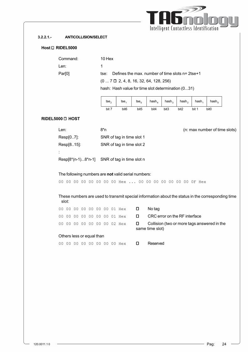
3.2.2.1.- ANTICOLLISION/SELECT
Host ⇒⇒⇒⇒⇒ RIDEL5000
Command: 10 Hex
Len: 1
Par[0] tse: Defines the max. number of time slots n= 2tse+1
(0 ... 7 ⇒⇒⇒⇒⇒ 2, 4, 8, 16, 32, 64, 128, 256)
hash: Hash value for time slot determination (0...31)
tse2 tse1 tse0 hash4 hash3 hash2 hash1 hash0
bit 7 bit6 bit5 bit4 bit3 bit2 bit 1 bit0
RIDEL5000 ⇒⇒⇒⇒⇒ HOST
Len: 8*n (n: max number of time slots)
Resp[0..7]: SNR of tag in time slot 1
Resp[8..15]: SNR of tag in time slot 2
:
Resp[8*(n-1)...8*n-1] SNR of tag in time slot n
The following numbers are not valid serial numbers:
00 00 00 00 00 00 00 00 Hex ... 00 00 00 00 00 00 00 0F Hex
These numbers are used to transmit special information about the status in the corresponding timeslot:
00 00 00 00 00 00 00 01 Hex ⇒⇒⇒⇒⇒ No tag
00 00 00 00 00 00 00 01 Hex ⇒⇒⇒⇒⇒ CRC error on the RF interface
00 00 00 00 00 00 00 02 Hex ⇒⇒⇒⇒⇒ Collision (two or more tags answered in thesame time slot)
Others less or equal than
00 00 00 00 00 00 00 00 Hex ⇒⇒⇒⇒⇒ Reserved

120.0011.1 0 Pag: 25
3.2.2.2.- READ
Host ⇒⇒⇒⇒⇒ RIDEL5000
Command: 11 Hex
Len: 2
Par[0] blnr: First block to be read (0..15)
Par[1] nobl: Number of blocks to be read (1..16)
RIDEL5000 ⇒⇒⇒⇒⇒ HOST
Len: n*(1+4*x) (n: max number of time slots)
Resp[0]: Status of time slot 1
Resp[1]: Status of time slot 2
:
Resp[n-1] Status of time slot n
Resp[n..n+3]: Block m, time slot 1
:
Resp [n+4*(x-1)...n+4*x-1]: Block m+x-1, time slot 1.
:
Resp [n+4*x*(n-1)...n+4*x(n-1)+3]: Block m, time slot n.
:
Resp [n+4*(x*n-1)...n+4*x*n-1]: Block m+x-1, time slot n
The status byte contain the information concerning possible errors which occurred in the correspondingtime slot.
Status: 00 Hex ⇒⇒⇒⇒⇒ No Error
01 Hex ⇒⇒⇒⇒⇒ No tag
02 Hex ⇒⇒⇒⇒⇒ CRC Error on the RF interface
03 Hex ⇒⇒⇒⇒⇒ Collision (two or more tags answered in the same timeslot)
04 Hex ⇒⇒⇒⇒⇒ Weak collision (two or more tags answered in the sametime slot, but the response of one tag was clear)

120.0011.1 0 Pag: 26
3.2.2.3.- READ UNSELECTED
Host ⇒⇒⇒⇒⇒ RIDEL5000
Command: 12 Hex
Len: 3
Par[0] tse: Defines the max. number of time slots n= 2tse+1
(0 ... 7 ⇒⇒⇒⇒⇒ 2, 4, 8, 16, 32, 64, 128, 256)
hash: Hash value for time slot determination (0...31)
tse2 tse1 tse0 hash4 hash3 hash2 hash1 hash0
bit 7 bit6 bit5 bit4 bit3 bit2 bit 1 bit0
Par[1] blnr: First block to be read (0..15)
Par[2] nobl: Number of blocks to be read (1..16)
RIDEL5000 ⇒⇒⇒⇒⇒ HOST
Len: n*(1+4*x) (n: max number of time slots)
Resp[0]: Status of time slot 1
Resp[1]: Status of time slot 2
:
Resp[n-1] Status of time slot n
Resp[n..n+3]: Block m, time slot 1
:
Resp [n+4*(x-1)...n+4*x-1]: Block m+x-1, time slot 1.
:
Resp [n+4*x*(n-1)...n+4*x(n-1)+3]: Block m, time slot n.
:
Resp [n+4*(x*n-1)...n+4*x*n-1]: Block m+x-1, time slot n
The status byte contain the information concerning possible errors which occurred in the correspondingtime slot.
Status: 00 Hex ⇒⇒⇒⇒⇒ No Error
01 Hex ⇒⇒⇒⇒⇒ No tag
02 Hex ⇒⇒⇒⇒⇒ CRC Error on the RF interface
03 Hex ⇒⇒⇒⇒⇒ Collision (two or more tags answered in the same timeslot)
04 Hex ⇒⇒⇒⇒⇒ Weak collision (two or more tags answered in the sametime slot, but the response of one tag was clear)

120.0011.1 0 Pag: 27
3.2.2.4.- WRITE
Host ⇒⇒⇒⇒⇒ RIDEL5000
Command: 13 Hex
Len (rounded off to next integer): 6+(n+7)/8
Par[0]: hash: Hash value for acknowledgment (0..31)
Par[1]: blnr: Block to be written (0..15)
Par[2]: data[0]: Byte 0 of block blnr
Par[3]: data[1]: Byte 1 of block blnr
Par[4]: data[2]: Byte 2 of block blnr
Par[5]: data[3]: Byte 3 of block blnr
Par[6]..Par[Len-1]: Timeslots: Information in which time sot the corresponding tagshould be written
TS8 TS7 TS6 TS5 TS4 TS3 TS2 TS1
bit 7 bit6 bit5 bit4 bit3 bit2 bit 1 bit0
TSn TSn-1 TSn-2 TSn-3 TSn-4 TSn-5 TSn-6 TSn-7
bit 7 bit6 bit5 bit4 bit3 bit2 bit 1 bit0
:
TSx = 0 Function doesn´t write to tag in time slot x
TSx = 1 Function writes to tag in time slot x
RIDEL5000 ⇒⇒⇒⇒⇒ HOST
Len: n (n: max number of time slots)
Resp[0]: Status of time slot 1
Resp[1]: Status of time slot 2
:
Resp[n-1] Status of time slot n
Status: 00 Hex ⇒⇒⇒⇒⇒ No Error
01 Hex ⇒⇒⇒⇒⇒ No tag
02 Hex ⇒⇒⇒⇒⇒ CRC Error on the RF interface
03 Hex ⇒⇒⇒⇒⇒ Collision (two or more tags answered in the same timeslot)
04 Hex ⇒⇒⇒⇒⇒ SNR is not identical withthe expected one in thecorresponding time slot
10 Hex ⇒⇒⇒⇒⇒ ‘No Write’ OK:Tag at corresponding time slot was notwritten to (according to the command)

120.0011.1 0 Pag: 28
3.2.2.5.- HALT
Host ⇒⇒⇒⇒⇒ RIDEL5000
Command: 14 Hex
Len (rounded off to next integer): (n+7)/8
Par[0]: hash: Hash value for acknowledgment (0..31)
Par[1]..Par[Len-1]: Timeslots: Information in which time sot the corresponding tagshould be set in halt mode
TS8 TS7 TS6 TS5 TS4 TS3 TS2 TS1
bit 7 bit6 bit5 bit4 bit3 bit2 bit 1 bit0
TSn TSn-1 TSn-2 TSn-3 TSn-4 TSn-5 TSn-6 TSn-7
bit 7 bit6 bit5 bit4 bit3 bit2 bit 1 bit0
:
TSx = 0 Function doesn´t set the tag in time slot x in halt mode
TSx = 1 Function sets the tag in time slot x in halt mode
RIDEL5000 ⇒⇒⇒⇒⇒ HOST
Len: n (n: max number of time slots)
Resp[0]: Status of time slot 1
Resp[1]: Status of time slot 2
:
Resp[n-1] Status of time slot n
Status: 00 Hex ⇒⇒⇒⇒⇒ No Error
01 Hex ⇒⇒⇒⇒⇒ No tag
02 Hex ⇒⇒⇒⇒⇒ CRC Error on the RF interface
03 Hex ⇒⇒⇒⇒⇒ Collision (two or more tags answered in the same timeslot)
04 Hex ⇒⇒⇒⇒⇒ SNR is not identical withthe expected one in thecorresponding time slot
10 Hex ⇒⇒⇒⇒⇒ ‘No Halt’ OK:Tag at corresponding time slot was notset into halt mode (according to the command)

120.0011.1 0 Pag: 29
3.2.2.6.- RESET QUIET BIT
Host ⇒⇒⇒⇒⇒ RIDEL5000
Command: 15 Hex
Len: 0
RIDEL5000 ⇒⇒⇒⇒⇒ HOST
Len: 0
3.2.2.7.- EAS FUNCTION
Host ⇒⇒⇒⇒⇒ RIDEL5000
Command: 16 Hex
Len: 0
RIDEL5000 ⇒⇒⇒⇒⇒ HOST
Len: 1
Resp[0]: Status
Status: 00 Hex ⇒⇒⇒⇒⇒ No tag or tag with disabled EAS in the field
FF Hex ⇒⇒⇒⇒⇒ One or more tags with enabled EAS bit in the field (EASalarm)
Any value of Stagus between 00 Hex and FF Hex is possible.
Examples: <40 Hex ⇒⇒⇒⇒⇒ No EAS alarm (caused by disturbances)
>=40 Hex ⇒⇒⇒⇒⇒ EAS alarm (tag not completely in the field)

120.0011.1 0 Pag: 30
3.3.- RIDEL5000 COMMANDS
3.3.1.- RIDEL5000 CONFIGURATION COMMANDS
CFG_RF_PAUSE_INIT 0CFG_INIT 1CFG_DEFAULT 2 CFG_EAS_LEVEL 3 CFG_EAS_LENGTH 4 CFG_PULSE_OFFSET 5 CFG_PULSE_LENGTH 6 CFG_RF_OFF_ON 7 CFG_FAST_MODE 8 CFG_FAMILY_CODE 9 CFG_APPLICATION_ID 10 CFG_MOD_DEPTH 11 CFG_RF_POWER 12 CFG_FAST_OFFSET 13 CFG_FAST_LENGTH 14 CFG_START_OFFSET 15CFG_TEST_MODULACION 16CFG_TUNE_VOLTAGE 17CFG_AGC 18CFG_EEPROM 19CFG_DIR_EEPROM 20CFG_SAVE_CONFIG 21CFG_RXFILTER 22CFG_RF_VALUE 23CFG_SLICER 24CFG_RF_ON 25CFG_RF_OFF 26CFG_CSTX1 27CFG_CPTX1 28CFG_CSTX2 29CFG_CPTX2 30CFG_MODE 31CFG_MEM_INDEX 32CFG_TX_TUNER 33CFG_TIME_1 34CFG_TIME_2 35CFG_TIME_3 36CFG_TIME_4 37CFG_SER_OUT_0 38CFG_SER_OUT_1 39CFG_SER_OUT_2 40CFG_SER_OUT_3 41
3.3.2.- RIDEL5000 STATE COMMANDS
CRM_GET_TIMESLOTS 0CRM_GET_VERSION 1CRM_GET_NOISE_LEVEL 2CRM_GET_MOD_LEVEL 3CRM_GET_SYS_VARS 4CRM_GET_MEAS 5CRM_GET_EEPROM 6 CRM_GET_AD 7

120.0011.1 0 Pag: 31
3.3.3.- EEPROM INICIALIZATION ADDRESSES
EE_PROTOCOL 11 // 1 BYTEEE_485_ID_H 12 // 1 BYTESEE_485_ID_L 13 // 1 BYTESEE_TUNE_VOLTAGE 14 // 2 BYTESEE_AGC 16 // 2 BYTESEE_POWER 18 // 2 BYTESEE_MOD_INDEX 20 // 2 BYTESEE_REFLECTED_AL 22 // 2 BYTESEE_TEMPERATURE_1 24 // 2 BYTESEE_TEMPERATURE_2 26 // 2 BYTESEE_MODE 28 // 1 BYTEEE_MODE_1 29 // 1 BYTEEE_STAR_OFF 30 // 1 BYTEEE_PULSE_OFF 31 // 1 BYTEEE_PULSE_LEN 32 // 1 BYTEEE_FAST_OFF 33 // 1 BYTEEE_FAST_LEN 34 // 1 BYTEEE_EAS_LEVEL 35 // 1 BYTEEE_EAS_LEN 36 // 1 BYTEEE_CAL_TIME 37 // 2 BYTEEE_SLICER 39 // 2 BYTESEE_BAUDRATE 41 // 2 BYTESEE_ACT_ST_OUT 43 // 1 BYTEEE_MASK_EAS_RD 44 // 1 BYTEEE_RD_LEN 45 // 1 BYTEEE_CSTX1 46 // 1 BYTEEE_CPTX1 47 // 1 BYTEEE_CSTX2 48 // 1 BYTEEE_CPTX2 49 // 1 BYTEEE_CSRX1 50 // 1 BYTEEE_CPRX1 51 // 1 BYTEEE_CSRX2 52 // 1 BYTEEE_CPRX2 53 // 1 BYTE

120.0011.1 0 Pag: 32
3.4.- TAG-WORLD PROTOCOL
3.4.1.- CONTINOUS READ
Host ⇒⇒⇒⇒⇒ RIDEL5000 Command: cxx
Where xx is the block number between 0 and 15 in hexadecimal format. Example: 00
RIDEL5000 ⇒⇒⇒⇒⇒ HOST
Block 0: 8 bytes hexadecimal +CR +LF
Block 1-15: 4 bytes hexadecimal +CR +LF
Block >15: The whole memory content (64 bytes) +CR +LF
No return if tag is not detected
Example for block 0: EA1E4D0000000001 (serial number)
3.4.2.- READ
Host ⇒⇒⇒⇒⇒ RIDEL5000 Command: rxx
Where xx is the block number between 0 and 15 in hexadecimal format. Example: 05
RIDEL5000 ⇒⇒⇒⇒⇒ HOST
Block 0: 8 bytes hexadecimal +CR +LF
Block 1-15: 4 bytes hexadecimal +CR +LF
Block >15: The whole memory content (64 bytes) +CR +LF
No return if tag is not detected
Example for block 5: AAB01248
3.4.3.- WRITE
Host ⇒⇒⇒⇒⇒ RIDEL5000 Command: Wxxyyyyyyyy
Where xx is the block number between 2 and 15 hexadecimal, and yyyyyyyy are the data to write inhexadecimal format.
RIDEL5000 ⇒⇒⇒⇒⇒ HOST
W +CR +LF if operation is correct
N +CR +LF if not
3.4.4.- VERSION
Host ⇒⇒⇒⇒⇒ RIDEL5000 Commando: x
RIDEL5000 ⇒⇒⇒⇒⇒ HOST
Returns information about firmware version. It finishes with +CR +LF

120.0011.1 0 Pag: 33
3.5.- OPERATING MODES
The RIDEL5000 firmware incorporates different operating modes:
bit 1 a 1 Fast mode
bit 2 a 1 Auto EAS
bit 3 a 1 Auto READ
bit 4 a 1 Auto write
bit 5 a 1 Pass counter
bit 6 a 1 Automatic Tuning Unit control
Fast Mode. This is the fast operating mode in the PHILIPS protocol.
Auto EAS, Autonomous mode. The RIDEL5000 is looking only for the EAS bit. The selected outputport is activated when a tag with EAS bit active is detected.
Auto READ, Autonomous mode for tag reading. The memory content of the read tags is stored in theRIDEL5000 memory. All the data can be uploaded to a host when required.
Auto WRITE, Autonomous mode for reading and writing tags. The memory content of the read tagsis stored in the RIDEL5000 memory. All the data can be uploaded to a host when required.
Pass counter. For access control systems. The RIDEL5000 operates with input and output sensorsfor access control applications.
Automatic Tuning Unit control. The RIDEL5000 controls the Automatic tuning units conected to itsTX and RX antennas.

120.0011.1 0 Pag: 34
3.6.- INIZIALIZATION VARIABLES
The variables described here can be modified. They are stored in EEPROM, so that the RIDEL5000 will startwith the selected operating parameters.
IDRS485. This is the Identification or access code when working in RS485 configuration. Its value can rangefrom 0 to 255.
Baud Rate. Serial communication baud rate. It is possible to work with 9600, 14400, 19800, 28800, 56600 or115200 bauds.
Communication protocol. Operating communication serial protocol:
0.- PHILIPS compatible protocol
1.- ASCII Softrónica protocol
2.- NET Softrónica protocol
3.- TAG-WORLD protocol
Operating mode. Mode of operation. It is possible to combine several bits from the following;
bit 1 Fast mode
bit 2 Auto EAS
bit 3 Auto READ
bit 4 Auto write
bit 5 Pass counter
bit 6 Automatic Tuning Unit control
Output Power. The output power of the unit is stored here. It is stored as tenths of watt. For instance, 7W isrepresented as 70, and 3.5W is represented as 35.
Modulation Index. Initial modulation index for the transmitter. It is stored as a percentage. For example, a 25value means a modulation index of 25%.
Reflected Power Alarm. Level for reflected power alarm, represented as tenth of watts.
Temperature Alarm (Half power). Level for temperature alarm in ºC. When the unit reaches this temperature,the output power will be automatically halved..
Temperature Alarm (0 power). Level for second temperature alarm in ºC. When the unit reaches thistemperature, the output power will be automatically set to 0.
RX Tuning. Value for RX antenna tuner (between 0 and 255)
RX Gain. Intermediate frequency gain setting (between 0 and 255)
RX Threshold. Threshold for the RX slicer (between 0 and 255)

120.0011.1 0 Pag: 35
Start Offset. This parameter sets when the RX signal samples is started. (between 0 and 255)
Pulse Offset (slow mode). This parameter sets when the pulses corresponding to time-slots are sampled onthe RX protocol in slow mode (between 0 and 255)
Pulse Length (slow mode). Slow mode pulse length as a value between 0 and 255.
Pulse Offset (quick mode). This parameter sets when the pulses corresponding to time-slots are sampled onthe RX protocol in quick mode (between 0 and 255)
Pulse Length (quick mode). Quick mode pulse length as a value between 0 and 255.
EAS Activation level. Threshold for EAS activation between as a percentage between 0 and 100.
EAS Activation time. Sets the activation time for the digital output once the EAS activation level has beenreached. It is stored as tenth of seconds. For instance, a 20 in this parameter will activate a digital output during 2seconds once the EAS activation level has been reached.
Callibration Interval. Time in tenth of seconds for the callibration interval.
Digital Output mask. Active and inactive state definition of the RIDEL5000 output port. This indicates, forevery digital output of the RIDEL5000, its «active» state (active low or active high). It is defined as a mask:
Digital Outpu mask for EAS and READ. Digital Output Port activation mask for EAS or READ VALID operations.The bits with a logic 1, will be activated when the corresponding operation takes place:
RD Activation time. Sets the activation time for the digital output after a valid tag has been read. It is storedas tenth of seconds. For instance, a 20 in this parameter will activate a digital output during 2 seconds once the EASactivation level has been reached.
ATU Serial Capacitance TX1. Starting value for the serial capacitance for Automatic Tuning Unit TX 1.
ATU Paralell Capacitance TX1. Starting value for the paralell capacitance for Automatic Tuning Unit TX 1.
ATU Serial Capacitance RX1. Starting value for the serial capacitance for Automatic Tuning Unit RX 1.
ATU Paralell Capacitance RX1. Starting value for the paralell capacitance for Automatic Tuning Unit RX 1.
ATU Serial Capacitance TX2. Starting value for the serial capacitance for Automatic Tuning Unit TX 2.
ATU Paralell Capacitance TX2. Starting value for the paralell capacitance for Automatic Tuning Unit TX 2.
0000 1111 (LSB)Active State Inactive State
0010 0001 (LSB)Lectura etiquetas Lectura Eas
Puerto 4Puerto 3Puerto 2Puerto 1
Puerto 1Puerto 2Puerto 3Puerto 4

120.0011.1 0 Pag: 36
ATU Serial Capacitance RX2. Starting value for the serial capacitance for Automatic Tuning Unit RX 2.
ATU Paralell Capacitance RX2. Starting value for the paralell capacitance for Automatic Tuning Unit RX 2.
3.7.- DEFAULT VALUES
The factory stored values are:
IDRS485 0
Baud Rate 115200
Communication Protocol 0
Operating Mode 0
Output Power 40
Modulation Index 150
Reflected Power Alarm Level 20
Temperature Alarm Level (1/2 power) 80
Temperature Alarm Level (0 power) 90
RX Tuning value 128
RX Gain 10
RX Threshold 40
Start Offset 8
Pulse Offsett (slow mode) 6
Pulse Length (slow mode) 12
Pulse Offsett (quick mode) 20
Pulse Length (quick mode) 32
EAS Activation level 64
EAS Activation time 20
Callibration interval 60
Digital Output mask 15
EAS and READ Output mask 1
RD Activation time 10
ATU Serial Capacitance TX1 0
ATU Paralell Capacitance TX1 0
ATU Serial Capacitance RX1 0
ATU Paralell Capacitance RX1 0
ATU Serial Capacitance TX2 0
ATU Paralell Capacitance TX2 0
ATU Serial Capacitance RX2 0
ATU Paralell Capacitance RX2 0

120.0011.1 0 Pag: 37
4.- TECHNICAL SPECIFICATION

120.0011.1 0 Pag: 38
4.1.- ELECTRICAL SPECIFICATIONS
4.1.1.- RADIO
Working Frequency 13.56MHz
Protocol I-CODE
Transmitted Power 0-10W software adjustable
Receiver sensibility Better than 20uV
Software Adjustment Transmitted power, Modulation index, IF Gain, InputFilter
Measurements Transmitted Power, Reflected Power, SWR, Internaltemperature
RF Connectors 2xBNC. One or two antennas configuration
4.1.2.- COMMUNICATION
Communication ports RS232 / RS485
Baud Rate 9600-115200 baud
RS232 Connector Standard DB9 Female
RS485 Connector DB15 Female
4.1.3.- I/O PORTS
Nº of input ports 4
Current/Voltage relation Draws 10mA @ 24Vcc
Nº of output ports 4
Max. Current/Voltage 6.7A, 30Vcc
4.1.4.- POWER SUPPLY
Input Voltage 24Vcc ±2%
Max. current 1.5A
4.1.5.- ENVIROMENTAL
Working Temperature -20 to +55ºC
Cooling fan incorporated
4.1.6.- CE MARKING
EN50081-1 General Electromagnetic compatibility Standar for emissions. Part I.Residential, commercial and light industry.
EN50082-1 General Electromagnetic compatibility Standaar for Inmunity. Part I.Residential, commercial and light industry.

120.0011.1 0 Pag: 39
4.2.- PHISICAL DIMENSIONS
120
71
00
12
2
21
,25
21
,25
65
35
60 60
22,5 22,5 15
100/
122
120
35,25

120.0011.1 0 Pag: 40
5.- INSTALLATION

120.0011.1 0 Pag: 41
5.1- CONTENTS AND UNPACKING
The RIDEL5000 is shipped in a box containing the following elements:
• The RIDEL5000 Module
• The equipment documentation
• The warranty document
• The CE Declaration of Conformity
Before unpacking, please check if the set has suffered any external damage or the unit inside has anyflow. In this case, please, contact your distributor to change the unit for a new one.
5.2.- STORAGE
The storage temperature for the equipment has to be kept between -40 and +85ºC. Keep it in a dryplace.

120.0011.1 0 Pag: 42
5.3.- INSTALATION
5.3.1.- REQUIRED ELEMENTS
To install the RIDEL5000 with RS232 control, the required elements are:
• The controlling computer or system
• One 24Vcc and 1.5A power supply
• The power supply cables (the mains cord and the unit cable, with + inside)
• Antenna as required and antenna cable.
If the unit is to work with RS485 control, it will also be neccesary the RS232 to RS485 adapter (if the finalcontrolling element has a RS232 interface). It will also be neccesary to install terminating resistors in the begeningand end of the RS485 bus, as required.
5.3.2.- POWER SUPPLY/POWER CONSUMPTION
Power is supplied to the unit via the power supply connector. The required power supply features are:
Voltage: +24Vcc
Current: +1.5A min
The power is connected to the unit throug a 2.5mm jack plug (center +)
WARNING.- To minimize risk of electric shock and warranty propper operation of the unit, the powersupply should be certified by UL, VDE, CS. The adapter and the personal computer connected to thisproduct should also be certified. The CE conformity test for the unit has been carried out with the ASTECSA45-3109 power supply.
5.3.3.- OVERVOLTAGE/REVERSE POLARITY
Before installing the unit is neccesary to check the correct polarity and voltage value in the powersupply connector. The unit will be damaged if the polarity is reversed or an overvoltage occurs.
5.3.4.- ANTENNA
The antenna should be the first connected element. The antenna cable length is important to the performanceof the unit, and should be considered when designing the antenna. The ANTMR5000 standard medium range antennarequires a 3m coaxial cable to assure its proper operation.
The antenna cable should be coaxial of RG58/U type, with a characteristic impedance of 50 ohm.
The unit is shipped in the one-antenna mode. In this mode, the antena shall be connected to the RFOUTconnector.
If the application requires the configuration of the unit in the two-antenna mode, the unit will have to be openedand a jumper will have to be installed. Follow the next procedure:
• Open the unit by removing the 4 screws that fix the cover of the equipment.
• Install the jumper for the 1 antenna configuration and remove it for TX/RX separated antennas

120.0011.1 0 Pag: 43
• Close the unit again, being sure to leave it in the same position as originally (see the fan positionfor reference)
The position of the jumper can be seen in the following diagram.
Antenna
selection
Jumper
5.3.5.- MECHANICAL CONSIDERATIONS
There are some important considerantion to have in mind about the propper phisical location of the unit.
• It is neccesary to leave a free area around the ventilation slots in both sides of the unit
• It is also neccesay not to block the air flow throug the ventilation fan
The neccesary air gaps are depicted in the following figure.
������������������������������������
������������������������������������
������������������������������
30mm30mm
40mm
The unit incorporates four drill holes in the base, with M3 thread, and 3mm depth. The drilling diagram isdepicted in the following figure.

120.0011.1 0 Pag: 44
87.12mm
69.34mm
34.67mm
43.56mm
5.3.5.- COMMUNICATION AND I/OCABLES
The RS232 cable for a PC conection will have the following pin conections:
RIDEL5000 PCSUBD 9V M SUBD 9V H
2 -------------------------------------------------------------------------------------------------- 23 -------------------------------------------------------------------------------------------------- 35 -------------------------------------------------------------------------------------------------- 5
The RS485 and I/O cable will be configured as follows:
RIDEL5000SUBD 15V M
11 ------------------------------------------------------------------------------------------------- INPUT 112 ------------------------------------------------------------------------------------------------- INPUT 25 -------------------------------------------------------------------------------------------------- INPUT 34 -------------------------------------------------------------------------------------------------- INPUT 49 -------------------------------------------------------------------------------------------------- GROUND INPUT6 -------------------------------------------------------------------------------------------------- OUTPUT 113 ------------------------------------------------------------------------------------------------- OUTPUT 28 -------------------------------------------------------------------------------------------------- OUTPUT 37 -------------------------------------------------------------------------------------------------- OUTPUT 42 -------------------------------------------------------------------------------------------------- GROUND OUTPUT14 ------------------------------------------------------------------------------------------------- A (+) RS48515 ------------------------------------------------------------------------------------------------- B (-) RS485
5.3.6.- STARTUP PROCEDURE
The following steps (in this order) should be followed when installing the unit.
• Connect the antenna cable and the antenna
• Connect the mains cord to your power supply (if neccesary)

120.0011.1 0 Pag: 45
• Connect the communication and I/O cables as required
• Plug the power supply connector into the RIDEL5000
Be sure that the antenna cable and conexions are correct before powering the unit.
Once connected, the power indicator will light permanently, and the «activity» indicator will flash signaling thecorrect finishing of the self-test routine.
5.4.- CABLE CONNECTION EXAMPLES
In the following diagram it is possible to see the RS232-one antenna configuration mode:
The RS485-two antenna mode can be seen in the following diagram:
Output
F.A: 24VccAntenna TX/RX
RS232
CBL02
CBL03
Input
SK05
SK03
SK01SK04
SK02
RS485
Inputs
F.A: 24Vcc
Antenna RX
Antenna TX
CBL01Outputs
SK05
SK03
SK01SK04

120.0011.1 0 Pag: 46
6.- TROUBLESHOOTING

120.0011.1 0 Pag: 47
6.1.- TEST PROCEDURE
The procedure to test the unit doesn´t require any special measurement equipment. It is only neccesaryto verify some standard points in any RF system to check.
6.2.- PRELIMINAR TESTS
As described in the INSTALLATION chapter, before connecting the RIDEL5000, it will be neccesary topay special attention to the Power Supply voltage and polarity in the power plug. The voltage will be 24Vcc andthe polarity will be as depicted in the case and in the following diagram.
+24Vcc
The antenna conection will also be checked. It is important to have in mind that the cable conexion withthe antenna is relevant to the unit performance. The cable should be supplied by the antenna manufacturer, orit will be built according its technical specifications.
WARNING.- The antennas developed for RFID systems are calculated to work with this type ofequipment. It is not recommended to connect radiocommunication antennas or other models notdefined by RFID equipment manufacturers or suppliers. The conection of non adequate equipmentin the antenna conectors, can cause damage to the unit.
6.3.- POWER ON
When connecting the unit, the first event to observ is the ON state in the «power» LED (D1). The«activity» LED (D2) will also flash indicating the proper equipment operation. See the LED position in thefollowing diagram.
SK03
D2
D1

120.0011.1 0 Pag: 48
6.4.- RF AND COMMUNICATION MEASUREMENTS
With the control system connected, check the communication link between the computer and the RIDEL5000.It will be neccesary to use your own control program or any dianostic software, like the one includen in the Softrónica`sKRFID5000 I-CODE Starter Kit.
If it is possible to have a RF Power Meter, for 13.56MHz, check the Incident Power, the Reflected Power, andso, the coupling between the RIDEL5000 and the antenna.
WARNING.- The Reflected Power will not exceed the 3W level. A higher reflected power indicates adamage or decoupling in the antenna. In this situation, the RIDEL5000 will try to protect itself and itsoperation will not be correct. The continued connection of the RIDEL5000 in this condition, can causedamage to its RF circuits.
If you have a diagnostic computer program, as the one supplied by Softrónica in the KRFID5000 I-CODEStarter Kit, it will be possible to check the same measurements in the «TX Measurements» window.
6.5.- LABEL READING TEST
Check the propper operation of the equipment by reading some I-CODE labels in EAS and random readingmodes. You can do it by placing a label near the antenna and watching the results in your computer application.
It is possible to check it with the diagnostics computer program supplied by Softrónica in its KRFID5000 I-CODE Starter Kit, in the «RX Measurements» window.


![NXP JCOP Java Card Product Range - cardlogix.com · NXP NFC IC’s Product Features PN512 PN532 PN533 PN544 Operating distance up to [mm] (1) 70 70 70 70 ... 13.56 13.56 13.56 13.56](https://img.dokumen.tips/doc/110x75/5b9cc5d209d3f2df1f8b81a9/nxp-jcop-java-card-product-range-nxp-nfc-ics-product-features-pn512-pn532.jpg)