Embed Size (px)
Citation preview

ARMY TM 9-6115-751-10 AIR FORCE TO 35C2-3-533-1
MARINE CORPS TM 11773A-OI NAVY TM 7610-LL-L1A-0024
DISTRIBUTION STATEMENT A — Approved for public release; distribution is unlimited.
HEADQUARTERS, DEPARTMENTS OF THE ARMY, AIR FORCE, NAVY, AND HEADQUARTERS,
US MARINE CORPS 1 FEBRUARY 2011
PCN 184 117730 00
TECHNICAL MANUAL
OPERATOR’S MANUAL
FOR
GENERATOR SET, SKID MOUNTED
15KW ADVANCED MEDIUM MOBILE POWER SOURCES (AMMPS)
MEP-1050 50/60 Hz (NSN: 6115-01-561-7634) (EIC: N/A)
MEP-1051 400 Hz (NSN: 6115-01-561-7674) (EIC: N/A)


TM 9-6115-751-10
WARNING SUMMARY
FIRST AID
For First Aid information, refer to Field Manual (FM) 4-25.11.
5 SAFETY STEPS TO FOLLOW IF SOMEONE IS THE VICTIM OF ELECTRICAL SHOCK:
Do not try to pull or grab the individual.
If possible, turn off the electrical power.
If you cannot turn off the electrical power, pull, push, or lift the person to safety using a dry wooden pole, dry rope, or some other insulating material.
Send for help as soon as possible.
After the injured person is free of contact with the source of electrical shock, move the person a short distance away. Immediately start artificial respiration if necessary.
a
TM 9-6115-751-10
The Warning Summary summarizes critical safety and hazardous material warnings that must be understood and applied during operation and maintenance of the Advanced Medium Mobile Power Sources (AMMPS) generator sets.
These warnings are important.
Study and understand all warnings.
These warnings can save your life and the lives of personnel with whom you work.
Some general warnings found in the Warning Summary will not be repeated within the Technical Manual (TM).
Specific warnings will be listed above the task or paragraph to which they apply.
Operation and maintenance of the AMMPS generator set contains many possibilities for injury or death to personnel. Be sure to be familiar with general first aid procedures as references in FM 4-25.11, First Aid.
WARNING ICONS
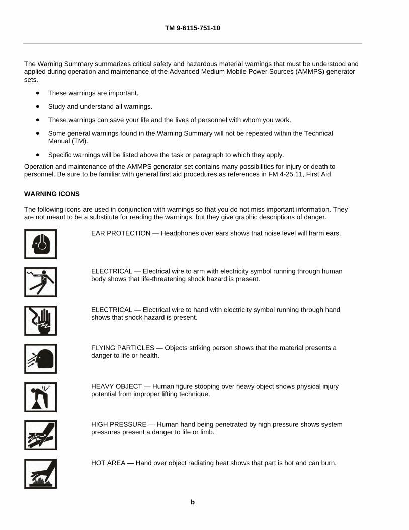
The following icons are used in conjunction with warnings so that you do not miss important information. They are not meant to be a substitute for reading the warnings, but they give graphic descriptions of danger.
EAR PROTECTION — Headphones over ears shows that noise level will harm ears.
ELECTRICAL — Electrical wire to arm with electricity symbol running through human body shows that life-threatening shock hazard is present.
ELECTRICAL — Electrical wire to hand with electricity symbol running through hand shows that shock hazard is present.
FLYING PARTICLES — Objects striking person shows that the material presents a danger to life or health.
HEAVY OBJECT — Human figure stooping over heavy object shows physical injury potential from improper lifting technique.
HIGH PRESSURE — Human hand being penetrated by high pressure shows system pressures present a danger to life or limb.
HOT AREA — Hand over object radiating heat shows that part is hot and can burn.
b

TM 9-6115-751-10
MOVING PARTS — Human figure with an arm caught between the gears shows that the larger moving parts of the equipment present a danger to life or limb.
MOVING PARTS — Hand with fingers caught between gears shows that the smaller moving parts of the equipment present a danger to life or limb.
WARNING DESCRIPTIONS
WARNING
Electrical
High voltage is produced when generator set is in operation. Never attempt to start the generator set unless it is properly grounded. Do not ground yourself in standing water. Never attempt to connect or disconnect load cables while the generator set is running. Failure to comply may cause injury or death to personnel.
Ensure generator sets are shut down and output terminal board has no voltage prior to making any connections for operation or moving a generator set that has been operating. Operating generator sets always contain the risk of electrocution. Failure to comply may cause injury or death to personnel.
Ensure generator sets are shut down and output terminal board has no voltage prior to making any connections for parallel operation or moving a generator set that has been operating in parallel. Operating generator sets always contain the risk of electrocution. Failure to comply may cause injury or death to personnel.
Direct Current (DC) voltages are present at generator set electrical components even with generator set shut down. Avoid shorting any positive with ground/negative. Do not ground yourself in standing water. Failure to comply may cause injury or death to personnel and damage to equipment.
Generator set must be completely shut down prior to washing. Electrocution is possible. Failure to comply may cause injury or death to personnel.
Do not start generator set until all internal components are completely dry. Electrocution is possible. Failure to comply may cause injury or death to personnel.
North Atlantic Treaty Organization (NATO) slave receptacle is electrically live at all times and is not protected by a fuse. Disconnecting main DC circuit breaker does not ensure the circuit is dead. This circuit is only dead when the batteries are fully disconnected. Disconnect both batteries before performing maintenance on the slave receptacle. Failure to comply may cause injury or death to personnel.
c
TM 9-6115-751-10
WARNING
Electrical — Continued.
Power is available to the Ground Fault Circuit Interrupter (GFCI) convenience receptacle only when the main contactor is closed. Avoid accidental contact. Electrocution is possible. Failure to comply may cause injury or death to personnel.
Ensure the frequency of any device powered by the GFCI convenience receptacle matches the frequency of the generator set. Failure to comply can cause serious injury or death to personnel.
High voltage is produced when this generator set is in operation. Do not contact output cables when operating this generator set. Failure to comply may cause injury or death to personnel.
High voltage is produced when generator set is in operation. Do not connect to a load that is not protected with appropriate safety devices. Do not connect from output terminal board to output terminal board unless directed by higher command. Never attempt to start the generator set unless it is properly grounded. Do not ground yourself in standing water. Never attempt to connect or disconnect load cables while the generator sets are running. Do not contact output cables when operating this generator set. Make sure that the connection between generator set and load is completely deenergized (safety device opens circuit) prior to disconnecting load cables or performing maintenance on the output terminal board. Failure to comply may cause injury or death to personnel.
High-voltage power is available when the main contactor is closed. Avoid accidental contact with live components. Ensure load cables are properly connected and the load cable door is shut before closing main contactor. Ensure that personnel working with/on loads connected to the generator set are aware that main contactor is about to be closed before closing main contactor. Failure to comply may cause injury or death to personnel.
Shut down generator sets before performing inspection of load cables. Failure to comply may cause injury or death to personnel by electrocution.
Generator set operator is permitted to make connections to output terminal board only. Connections to load distribution points or to equipment beyond the output terminal board shall only be made by properly trained and authorized personnel. Failure to comply may cause injury or death to personnel.
Do not remove the bonding jumper between GND and N unless the weapon system requires an underground system. Refer to applicable weapon system TM for specific guidance on power and connection requirements. Failure to comply may cause injury or death to personnel.
Ensure frequency of any device powered by the GFCI convenience receptacle matches the frequency of the generator set. Failure to comply can cause serious injury or death to personnel.
d

TM 9-6115-751-10
WARNING
Heat
When operating, generator set engine has hot metal surfaces that will burn flesh on contact. Shut down generator set and allow engine to cool before checks, services, and maintenance. Wear gloves and additional protective clothing as required. Failure to comply may cause injury or death to personnel.
When operating, muffler has hot metal surfaces that will burn flesh on contact. Shut down generator set and allow muffler to cool before performing maintenance. Wear gloves and additional protective clothing as required. Failure to comply may cause injury or death to personnel.
Top and housing panels can get very hot. Allow panels to cool down before performing maintenance. Wear gloves and additional protective clothing as required. Failure to comply may cause injury or death to personnel.
Wear heat-resistant gloves and avoid contacting hot metal surfaces with hands and exposed skin after components have been heated. Wear additional protective clothing as required. Failure to comply may cause injury or death to personnel.
When operating, turbocharger has hot metal surfaces that will burn flesh on contact. Shut down generator set and allow heater to cool before performing maintenance. Wear gloves and additional protective clothing as required. Failure to comply may cause injury or death to personnel.
WARNING
Jewelry/Clothing
Metal jewelry can conduct electricity and become entangled in generator set components. Remove all jewelry and do not wear loose clothing when working on equipment. Failure to comply may cause injury or death to personnel.
While inspecting the operation of the generator set, do not inadvertently reach into the generator set. Failure to comply can cause injury or death to personnel.
e

TM 9-6115-751-10
WARNING
Lifting
Comply with all lifting requirements. Observe the decals on equipment and parts that identify the weight and determine if assistance is needed. Maximum lift is 37 lb (16.8 kg) for one person, 74 lb (33.6 kg) for two persons, and 101 lb (45.8 kg) for three persons. Failure to comply may cause injury or death to personnel.
HAZARDOUS MATERIALS ICONS
BIOLOGICAL — Abstract symbol bug shows that material may contain bacteria or viruses that present a danger to life or health.
CHEMICAL — Drops of liquid on hand shows that material will cause burns or irritation to human skin or tissue.
CRYOGENIC — Hand in block of ice shows that material is extremely cold and can injure human skin or tissue.
EXPLOSION — Rapidly expanding symbol shows that material may explode if subjected to high temperature, source of ignition, or high pressure.
EYE PROTECTION — Person with goggles shows that material will injure the eyes.
FIRE — Flame shows that material may ignite and cause burns.
POISON — Skull and crossbones show that material is poisonous or is a danger to life.
RADIATION — Three circular wedges show that material emits radioactive energy and can injure human tissue.
f
TM 9-6115-751-10
VAPOR — Human figure in a cloud shows that material vapors present a danger to life or health.
HAZARDOUS MATERIALS WARNING DESCRIPTIONS
There is a potential risk that soldiers and other users may be exposed to chemical substances and diesel engine exhaust during the operation, maintenance, and repair of the AMMPS generator sets.
Potential sources of chemical substances include fuels, oils, lubricants, paints, cleaners/solvents, engine coolant fluids, cold start fluid, fire extinguishing agents, battery acid/chemicals, and miscellaneous chemicals used during the setup/operation/maintenance and sustainment throughout the life-cycle of the AMMPS generator sets.
WARNING
This manual describes physical and chemical processes that may require the use of chemicals, solvents, paints, and/or other commercially available material. Users of the manual should obtain the Material Safety Data Sheets (MSDS) (Occupational Safety and Health Act (OSHA) Form 20 or equivalent) from the manufacturers or suppliers of materials to be used. Failure to comply with comply with all procedures, recommendations, warnings and cautions for safe use, handling, storage, and disposal of these materials may result in serious injury or death to personnel.
WARNING
Batteries
Batteries give off combustible gas. Do not smoke or use open flame when performing maintenance. Failure to comply may cause injury or death to personnel and damage to equipment.
Battery acid can cause burns to skin and cause eye injury. Wear safety goggles and chemical gloves and avoid acid splash while working on the batteries. Failure to comply may cause injury or death to personnel.
WARNING
Cold
In extremely cold weather, skin can stick to metal. Avoid contacting metal items with bare skin in extremely cold weather. Failure to comply may cause injury or death to personnel.
g

TM 9-6115-751-10
WARNING
Exhaust
Hot exhaust gases can ignite combustible materials. Allow room for safe discharge of hot gases. Failure to comply may cause injury or death to personnel.
Exhaust discharge contains deadly gases, including carbon monoxide. Exhaust gases are most dangerous in places with poor ventilation. Do not operate generator set in an enclosed area unless exhaust discharge is properly vented. Failure to comply may cause injury or death to personnel.
Exhaust gases are most dangerous in places with poor ventilation. The best defense against exhaust gas poisoning is very good ventilation. To protect yourself and others, always obey the following rules:
Do not run engine indoors unless you have very good ventilation.
Do not idle engine for a long time unless there is very good ventilation.
Be alert at all times. Check for smell of exhaust fumes.
Failure to comply may cause injury or death to personnel.
Exhaust gas poisoning causes dizziness, headache, loss of muscle control, sleepiness, coma, and death. If anyone shows signs of exhaust gas poisoning, get all personnel clear of AMMPS. Make sure they have lots of fresh air. Keep them warm, calm, and inactive. Get medical help. If anyone stops breathing, give artificial respiration. Failure to comply may cause injury or death to personnel.
WARNING
Eye
Flying debris or material may enter eyes or strike the face. Wear appropriate eye/face protection while performing maintenance tasks. Failure to comply may cause injury or death to personnel.
h
TM 9-6115-751-10
WARNING
Fuel
Fuels used in the generator set are combustible. Do not smoke or use open fire when performing maintenance. Fire and possible explosion may result. Failure to comply may cause injury or death to personnel and damage to equipment.
Hot engine surfaces from engine and generator circuitry are possible sources of ignition. When refueling during unit operation with Diesel Fuel (DF)-1, DF-2, Jet Propulsion Fuel (JP) 5, or JP8, avoid fuel splash and fuel spill. Do not smoke or use open flame when performing refueling. Remember Preventive Maintenance Checks and Services (PMCS) are still required. Flames and possible explosion may result. Failure to comply may cause injury or death to personnel.
Fuel is combustible and toxic to eyes, skin, and respiratory tract. Skin and eye protection are required when working in contact with fuel. Avoid repeated or prolonged contact. Provide adequate ventilation. Operators are to wash exposed skin and change soaked clothing promptly if exposed to fuel. Failure to comply may cause injury or death to personnel.
Fuels used in the generator set are combustible. Ensure fuel source grounding strap is connected to unit fuel fill grounding stud (fuel fill static ground). When filling the fuel tank, maintain metal-to-metal contact between filler nozzle and fuel tank opening to eliminate Electrostatic Discharge (ESD). Fire and possible explosion can result. Failure to comply may cause injury or death to personnel.
Do not operate generator set if any fuel leaks are present. Fuel is combustible. Always perform PMCS before operation. Failure to comply may cause injury or death to personnel.
WARNING
High Temperature/Pressure
Hot coolant can burn. If the radiator cap is hot to the touch, it is too hot to open. Allow the coolant to cool before opening the radiator cap. Wear gloves, additional protective clothing, and goggles as required. Contact with high-pressure steam and/or liquids can cause burns and scalding. Failure to comply may cause injury or death to personnel.
Cooling system operates at high temperature and pressure. Contact with high-pressure steam and/or liquids can cause burns and scalding. Shut down generator set and allow system to cool before performing checks, services, and maintenance. Wear gloves, additional protective clothing, and goggles as required. Contact with high-pressure steam and/or liquids can cause burns and scalding. Failure to comply may cause injury or death to personnel.
Engine coolant is toxic to eyes and poisonous if ingested. Eye protection is required when working with engine coolant. Avoid repeated or prolonged contact. Failure to comply may cause injury or death to personnel.
i

TM 9-6115-751-10
WARNING
High Temperature/Pressure — Continued.
Cooling system operates at high temperature and pressure. Contact with high-pressure steam and/or liquids can cause burns and scalding. Do not open radiator cap unless coolant temperature is below 100°F (38°C). Failure to comply may cause injury or death to personnel.
WARNING
Noise
Hearing protection requested during maintenance or repair with engine running. Failure to comply can cause hearing loss.
j

TM 9-6115-751-10
A/B blank USA
LIST OF EFFECTIVE PAGES/WORK PACKAGES
NOTE: Zero in the “Change No.” column indicates an original page or work package.
Date of issue for the original manual is:
Original 1 February 2011
TOTAL NUMBER OF PAGES FOR FRONT MATTER AND REAR MATTER IS 42 AND TOTAL NUMBER OF WORK PACKAGES IS 21, CONSISTING OF THE FOLLOWING:
Page/WP No. Change No. Front cover 0 Blank 0 Warning summary (8 pgs) 0 i – x 0 Chp 1 title page 0 Chp 1 index 0 WP 0001 (8 pgs) 0 WP 0002 (14 pgs) 0 WP 0003 (8 pgs) 0 Chp 2 title page 0 Chp 2 index 0 WP 0004 (24 pgs) 0 WP 0005 (54 pgs) 0 WP 0006 (20 pgs) 0 WP 0007 (8 pgs) 0 WP 0008 (4 pgs) 0 Chp 3 title page 0 Chp 3 index 0 WP 0009 (4 pgs) 0 WP 0010 (22 pgs) 0
Page/WP No. Change No. WP 0011 (4 pgs) 0 Chp 4 title page 0 Chp 4 index 0 WP 0012 (4 pgs) 0 WP 0013 (24 pgs) 0 WP 0014 (4 pgs) 0 WP 0015 (10 pgs) 0 WP 0016 (6 pgs) 0 WP 0017 (6 pgs) 0 Chp 5 title page 0 Chp 5 index 0 WP 0018 (2 pgs) 0 WP 0019 (4 pgs) 0 WP 0020 (2 pgs) 0 WP 0021 (2 pgs) 0 Glossary-1 – Glossary-2 0 INDEX-1 – INDEX-4 0 Inside back cover 0 Back cover 0


ARMY TM 9-6115-751-10 AIR FORCE TO 35C2-3-533-1
MARINE CORPS TM 11773A-OI NAVY TM 7610-LL-L1A-0024
DISTRIBUTION STATEMENT A –– Approved for public release; distribution is unlimited.
i
HEADQUARTERS, DEPARTMENTS OF THE ARMY, AIR FORCE, NAVY, AND HEADQUARTERS, US MARINE CORPS WASHINGTON, D.C., 1 FEBRUARY 2011
TECHNICAL MANUAL
OPERATOR’S MANUAL
FOR
GENERATOR SET, SKID MOUNTED
15KW ADVANCED MEDIUM MOBILE POWER SOURCES (AMMPS) MEP-1050 50/60 Hz
(NSN: 6115-01-561-7634) (EIC: N/A) MEP-1051 400 Hz
(NSN: 6115-01-561-7674) (EIC: N/A)
REPORTING ERRORS AND RECOMMENDING IMPROVEMENTS
You can help improve this manual. If you find any mistakes or if you know of a way to improve the procedures, please let us know. Reports, as applicable by the requiring Service, should be submitted as follows:
(a) (A) Army — Mail your letter or DA Form 2028 (Recommended Changes to Publications and Blank Forms) located in the back of this manual, directly to: Commander, U.S. Army CECOM Life Cycle Management Command (LCMC) and Fort Monmouth, ATTN: AMSEL-LC-LEO-E-CM, Fort Monmouth, NJ 07703-5006. You may also send in your recommended changes via electronic mail or by fax. Our fax number is 732-532-1556, DSN 992-1556. Our e-mail address is [email protected]. Our online web address for entering and submitting DA Form 2028s is http://edm.monmouth.army.mil/pubs/2028.html.
(b) (MC) Marine Corps — Submit notice of discrepancies or suggested changes on a NAVMC 10772.
The NAVMC may be submitted via the Internet using URL: http://192.156.19.109/ar/mcefs.nsf. Once the form is completed click on file in the tool bar at top of screen, scroll to "Send" and select "Page by email", and enter [email protected], this will come in to the Pubs Sections mailbox. This method of submittal does not require a Common Access Card (CAC) to access the form. The https://pubs.ala.usmc.mil/front.htm URL will allow access to the Albany Publications web site where the form can be filled out and be submitted by electronic mail to [email protected]. A paper copy NAVMC 10772 can be mailed in an envelope addressed to Commander, Marine Corps Systems Command (LOG/TP), 814 Radford Blvd, Suite 20343, Albany, GA 31704-0343. Problems or questions regarding the NAVMC 10772 program should be reported by calling DSN 567-7628, DSN 567-6439 or DSN 567-5017.
(c) (N) Navy — By letter directly to Commander, Space and Naval Warfare Systems Command,
ATTN: SPAWAR 8122, Washington, DC 20363-5100. (d) (F) Air Force — By Air Force AFTO Form 22 TM Change Recommendation and Reply in
accordance with paragraph 6-5, Section VI, TO 00-5-1 directly to prime ALC/MST. A reply will be furnished to you.
TM 9-6115-751-10
ii
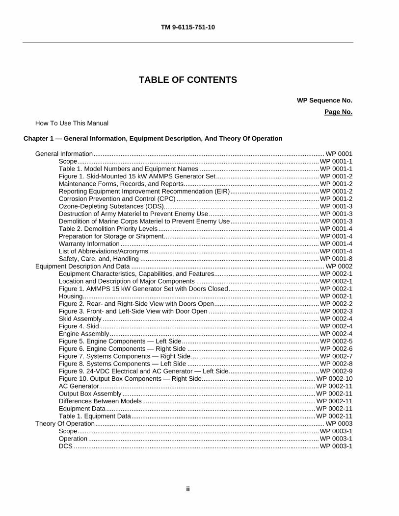
TABLE OF CONTENTS
WP Sequence No.
Page No.
How To Use This Manual
Chapter 1 — General Information, Equipment Description, And Theory Of Operation
General Information................................................................................................................................ WP 0001 Scope......................................................................................................................................WP 0001-1 Table 1. Model Numbers and Equipment Names ..................................................................WP 0001-1 Figure 1. Skid-Mounted 15 kW AMMPS Generator Set .........................................................WP 0001-2 Maintenance Forms, Records, and Reports...........................................................................WP 0001-2 Reporting Equipment Improvement Recommendation (EIR).................................................WP 0001-2 Corrosion Prevention and Control (CPC) ...............................................................................WP 0001-2 Ozone-Depleting Substances (ODS)......................................................................................WP 0001-3 Destruction of Army Materiel to Prevent Enemy Use.............................................................WP 0001-3 Demolition of Marine Corps Materiel to Prevent Enemy Use.................................................WP 0001-3 Table 2. Demolition Priority Levels .........................................................................................WP 0001-4 Preparation for Storage or Shipment......................................................................................WP 0001-4 Warranty Information ..............................................................................................................WP 0001-4 List of Abbreviations/Acronyms ..............................................................................................WP 0001-4 Safety, Care, and, Handling ...................................................................................................WP 0001-8 Equipment Description And Data ........................................................................................................... WP 0002 Equipment Characteristics, Capabilities, and Features..........................................................WP 0002-1 Location and Description of Major Components ....................................................................WP 0002-1
Figure 1. AMMPS 15 kW Generator Set with Doors Closed..................................................WP 0002-1 Housing...................................................................................................................................WP 0002-1 Figure 2. Rear- and Right-Side View with Doors Open..........................................................WP 0002-2 Figure 3. Front- and Left-Side View with Door Open .............................................................WP 0002-3 Skid Assembly ........................................................................................................................WP 0002-4 Figure 4. Skid..........................................................................................................................WP 0002-4 Engine Assembly....................................................................................................................WP 0002-4 Figure 5. Engine Components — Left Side............................................................................WP 0002-5 Figure 6. Engine Components — Right Side .........................................................................WP 0002-6 Figure 7. Systems Components — Right Side.......................................................................WP 0002-7 Figure 8. Systems Components — Left Side .........................................................................WP 0002-8 Figure 9. 24-VDC Electrical and AC Generator — Left Side..................................................WP 0002-9 Figure 10. Output Box Components — Right Side...............................................................WP 0002-10 AC Generator........................................................................................................................WP 0002-11 Output Box Assembly ...........................................................................................................WP 0002-11 Differences Between Models................................................................................................WP 0002-11 Equipment Data ....................................................................................................................WP 0002-11 Table 1. Equipment Data......................................................................................................WP 0002-11 Theory Of Operation............................................................................................................................... WP 0003 Scope......................................................................................................................................WP 0003-1 Operation ................................................................................................................................WP 0003-1 DCS ........................................................................................................................................WP 0003-1

TM 9-6115-751-10
iii
WP Sequence No.
Page No.
Figure 1. AMMPS Control Overview ...................................................................................... WP 0003-2 Technical Principles of Operation...........................................................................................WP 0003-2 Figure 2. Engine Starting System........................................................................................... WP 0003-3 Figure 3. Fuel System ............................................................................................................ WP 0003-4 Figure 4. Engine Cooling System........................................................................................... WP 0003-5 Figure 5. Engine Lubrication System ..................................................................................... WP 0003-6 Figure 6. Air Intake and Exhaust System............................................................................... WP 0003-7 Figure 7. Output Supply System............................................................................................. WP 0003-8
Chapter 2 — Operator Instructions
Descriptions And Use Of Operator Controls And Indicators .................................................................. WP 0004 Introduction............................................................................................................................. WP 0004-1 DCS ........................................................................................................................................ WP 0004-1 Figure 1. Screen Navigation ................................................................................................... WP 0004-1 Table 1. Screen Navigation .................................................................................................... WP 0004-2 Figure 2. Generator Set DCS Control Panel .......................................................................... WP 0004-3 Table 2. Generator Set DCS Control Panel ........................................................................... WP 0004-3 Figure 3. DCS Control Panel .................................................................................................. WP 0004-4 Table 3. DCS Control Panel ................................................................................................... WP 0004-4 Figure 4. DEAD CRANK SWITCH ......................................................................................... WP 0004-5 Table 4. DEAD CRANK SWITCH........................................................................................... WP 0004-5 Figure 5. Engine Control Switch.............................................................................................WP 0004-6 Table 5. Engine Control Switch ..............................................................................................WP 0004-6 Figure 6. Main DC Circuit Breaker ......................................................................................... WP 0004-7 Table 6. Main DC Circuit Breaker........................................................................................... WP 0004-7 Figure 7. Voltage Selection Board.......................................................................................... WP 0004-8 Table 7. Voltage Selection Board........................................................................................... WP 0004-8 Figure 8. Main Display Screen (Showing 3-Phase Configuration) ......................................... WP 0004-9 Table 8. Main Display Screen................................................................................................. WP 0004-9 Figure 9. [Adjustments] Screen 1 — Select Parameter ....................................................... WP 0004-13 Table 9. [Adjustments] Screen 1 — Select Parameter......................................................... WP 0004-13 Figure 10. [Adjustments] Screen 1 — Adjust ....................................................................... WP 0004-14 Table 10. [Adjustments] Screen 1 — Adjust......................................................................... WP 0004-15 Figure 11. [Adjustments] Screen 2 — Select Parameter ..................................................... WP 0004-16 Table 11. [Adjustments] Screen 2 — Select Parameter....................................................... WP 0004-16 Figure 12. [Adjustments] Screen 2 — Adjust ....................................................................... WP 0004-17 Table 12. [Adjustments] Screen 2 — Adjust......................................................................... WP 0004-18 Figure 13. [Parallel Adj] Screen............................................................................................WP 0004-19 Table 13. [Parallel Adj] Screen.............................................................................................WP 0004-19 Figure 14. First [Maintenance] Screen ................................................................................. WP 0004-20 Table 14. First [Maintenance] Screen .................................................................................. WP 0004-20 Figure 15. [Maintenance Items] Screen ............................................................................... WP 0004-21 Table 15. [Maintenance Items] Screen.................................................................................WP 0004-21 Figure 16. [Maintenance Actions] Screen ............................................................................ WP 0004-22 Table 16. [Maintenance Actions] Screen.............................................................................. WP 0004-22 Figure 17. Generator Hour Meter ......................................................................................... WP 0004-23 Table 17. Generator Hour Meter .......................................................................................... WP 0004-23 Operation Under Usual Conditions......................................................................................................... WP 0005 Siting Requirements ............................................................................................................... WP 0005-2 Assembly and Preparation for Use......................................................................................... WP 0005-3 Screen Navigation .................................................................................................................. WP 0005-3 Figure 1. Screen Navigation ................................................................................................... WP 0005-3

TM 9-6115-751-10
iv
WP Sequence No.
Page No.
Installation of Ground Rod......................................................................................................WP 0005-4 Figure 2. Grounding Connections...........................................................................................WP 0005-4 Figure 3. Install Ground Rod with Slide Hammer ...................................................................WP 0005-6 Figure 4. Installing Ground Rods with Sledge Hammer .........................................................WP 0005-7 Removal of Ground Rod.........................................................................................................WP 0005-9 Installation of Auxiliary Fuel Lines ........................................................................................WP 0005-10 Figure 5. Auxiliary Fuel Supply Connections........................................................................WP 0005-10 Installation of Load Cables ...................................................................................................WP 0005-11 Figure 6. Installation of Load and Ground Cables................................................................WP 0005-11 Table 1. Load Terminal —Voltage Selection Board .............................................................WP 0005-12 Figure 7. Ground and Output Cable Attachment Detail .......................................................WP 0005-12 Initial Adjustments ................................................................................................................WP 0005-13 Figure 8. Configure Voltage Selection Board .......................................................................WP 0005-14 Operating Procedures ..........................................................................................................WP 0005-15 Starting Procedure................................................................................................................WP 0005-15 Figure 9. Main DC Circuit Breaker and DEAD CRANK SWITCH ........................................WP 0005-16 Figure 10. DCS Panel...........................................................................................................WP 0005-17 Figure 11. Main Screen Message 1......................................................................................WP 0005-18 Table 2. Delay to Crank Messages ......................................................................................WP 0005-19 Figure 12. Main Screen Message 2......................................................................................WP 0005-19 Figure 13. Operator Main Screen.........................................................................................WP 0005-20 Adjust Generator Set ............................................................................................................WP 0005-21 Figure 14. Main Screen Showing Adjustments — Location .................................................WP 0005-21 Figure 15. [Adjustments] Screen 1 — Select Option............................................................WP 0005-22 Figure 16. [Adjustments] Screen 1 — Set Configuration .....................................................WP 0005-23 Figure 17. [Adjustments] Screen 2 — Select Parameter .....................................................WP 0005-24 Figure 18. [Adjustments] Screen 2 — Set Configuration .....................................................WP 0005-25 Monitoring Generator Set Operational Status ......................................................................WP 0005-26 Figure 19. Main Control Screen Status Indicators 120/208 V 3 Phase................................WP 0005-26 Table 3. Screen Indicator Parameters..................................................................................WP 0005-26 Figure 20. Select Maintenance Screen ................................................................................WP 0005-28 Figure 21. First Maintenance Screen ...................................................................................WP 0005-29 Figure 22. Maintenance Item Display...................................................................................WP 0005-30 Figure 23. Next Items Display ..............................................................................................WP 0005-31 Operation with Remote Monitoring.......................................................................................WP 0005-31 Figure 24. Operator Display Panel — Remote Connection .................................................WP 0005-32 Figure 25. Remote PC — Connection..................................................................................WP 0005-33 Figure 26. Remote PC Display .............................................................................................WP 0005-34 Stopping Procedure..............................................................................................................WP 0005-36 Figure 27. Stopping Procedure.............................................................................................WP 0005-36 Decals and Instructions Plates .............................................................................................WP 0005-37 Figure 28. Decals and Instructions Plates, Right-Side — Model 1050/1051 .......................WP 0005-37 Table 4. Decals and Instructions Plates, Right-Side — Model 1050/1051 ..........................WP 0005-37 Figure 29. Decals and Instructions Plates, Rear — Model 1050/1051 ................................WP 0005-38 Table 5. Decals and Instructions Plates, Rear — Model 1050/1051....................................WP 0005-38 Figure 30. Decals and Instructions Plates, Top and Inside — Model 1050/1051 ................WP 0005-39 Table 6. Decals and Instructions Plates, Top and Inside — Model 1050/1051 ...................WP 0005-39 Figure 31. Decals and Instructions Plates, Front — Model 1050/1051................................WP 0005-40 Table 7. Decals and Instructions Plates, Front — Model 1050/1051...................................WP 0005-40 Figure 32. Decals and Instructions Plates, Left-Side — Model 1050/1051..........................WP 0005-41 Table 8. Decals and Instructions Plates, Left-Side — Model 1050/1051.............................WP 0005-41 Figure 33. Plate, Identification — Model 1050 .....................................................................WP 0005-42 Figure 34. Plate, Identification — Model 1051 .....................................................................WP 0005-42

TM 9-6115-751-10
v
WP Sequence No.
Page No.
Figure 35. Name Plate, Identification — Model 1050........................................................... WP 0005-43 Figure 36. Name Plate, Identification — Model 1051........................................................... WP 0005-43 Figure 37. Label, Lifting and Tie Down — Model 1050/1051 ............................................... WP 0005-44 Figure 38. Plate, IUID Identification — Model 1050 ............................................................. WP 0005-44 Figure 39. Plate, IUID Identification — Model 1051 ............................................................. WP 0005-45 Figure 40. Plate, System Capacity — Model 1050/1051 ..................................................... WP 0005-45 Figure 41. Plate, Set Rating — Model 1050......................................................................... WP 0005-46 Figure 42. Plate, Set Rating — Model 1051......................................................................... WP 0005-46 Figure 43. Label, Fuel — Model 1050/1051 ......................................................................... WP 0005-47 Figure 44. Label, Convenience — Model 1050.................................................................... WP 0005-47 Figure 45. Label, Convenience — Model 1051.................................................................... WP 0005-47 Figure 46. Label, Fuel Diagram — Model 1050/1051 .......................................................... WP 0005-48 Figure 47. Label, Operating Instructions — Model 1050/1051............................................. WP 0005-49 Figure 48. Label, Dead Crank — Model 1050/1051............................................................. WP 0005-49 Figure 49. Label, Caution, Voltage Connection — Model 1050/1051.................................. WP 0005-50 Figure 50. Label, Grounding Stud — Model 1050/1051....................................................... WP 0005-50 Figure 51. Label, Diagram, Wiring — Model 1050/1051 ...................................................... WP 0005-51 Figure 52. Label, First Fuel Filter — Model 1050/1051........................................................ WP 0005-51 Figure 53. Label, Slave Receptacle — Model 1050/1051.................................................... WP 0005-52 Figure 54. Label, Schematic, Wiring — Model 1050/1051................................................... WP 0005-52 Figure 55. Label, Battery Connection — Model 1050/1051 ................................................. WP 0005-53 Preparation for Movement ....................................................................................................WP 0005-53 Parallel Operations ................................................................................................................................. WP 0006 Connecting Generator Sets Parallel Cables (Power Plant Configuration) ............................. WP 0006-2
Figure 1. Storage Box and Cable — Location........................................................................ WP 0006-3 Figure 2. DCS Panel — Parallel Setup .................................................................................. WP 0006-4
Parallel Operation with Switch Box (Two Like Sets) .............................................................. WP 0006-5 Figure 3. Switch Box Contactor Receptacle........................................................................... WP 0006-5 Figure 4. Main Display Screen — Parallel Mode....................................................................WP 0006-6 Parallel Operation Without Switch Box (Two Or More Like Sets) .......................................... WP 0006-8 Adjusting Parallel Operations ...............................................................................................WP 0006-11 Figure 5. Parallel Adjustment Screen, A .............................................................................. WP 0006-11 Figure 6. Parallel Adjustment Screen, B. ............................................................................. WP 0006-13
Figure 7. Parallel Adjustment Screen, C .............................................................................. WP 0006-15 Figure 8. Parallel Adjustment Screen, D .............................................................................. WP 0006-16 Figure 9. Parallel Adjustment Screen, E .............................................................................. WP 0006-17 Figure 10. Parallel Adjustment Screen, F............................................................................. WP 0006-18 Soft Removal From Parallel Operation With [Unload] Soft Key ........................................... WP 0006-19 Figure 11. Soft Unload Key ..................................................................................................WP 0006-19 Removal From Parallel Operation With UNIT PARALLEL Switch ....................................... WP 0006-20 Figure 12. DCS Panel, Remove From Parallel..................................................................... WP 0006-20 Operation Under Unusual Conditions..................................................................................................... WP 0007 Operation in Extreme Cold -25°F (-31°C)............................................................................... WP 0007-2 Operation in Extreme Heat Above 120°F (49°C) ................................................................... WP 0007-2 Operation in Dusty or Sandy Areas........................................................................................ WP 0007-2 Operation in Rainy or Humid Conditions ................................................................................WP 0007-3 Operation in Salt Water Areas................................................................................................ WP 0007-3 Operation in High Altitudes..................................................................................................... WP 0007-4 Operation Using BATTLESHORT Switch............................................................................... WP 0007-5 Figure 1. DCS Panel............................................................................................................... WP 0007-5 Operation While in Contaminated Areas ................................................................................ WP 0007-6 Use of the Ground Fault Circuit Interrupter (GFCI) Convenience Receptacle....................... WP 0007-7 Figure 2. GFCI Convenience Receptacle............................................................................... WP 0007-7
TM 9-6115-751-10
vi
WP Sequence No.
Page No.
Emergency.............................................................................................................................................. WP 0008 NATO Slave Receptacle Start Operation ...............................................................................WP 0008-1 Figure 1. NATO Slave Receptacle .........................................................................................WP 0008-2 Emergency Stopping ..............................................................................................................WP 0008-3 Figure 2. DCS Panel...............................................................................................................WP 0008-3 Operation Using BATTLESHORT Switch...............................................................................WP 0008-4
Chapter 3 — Troubleshooting Procedures
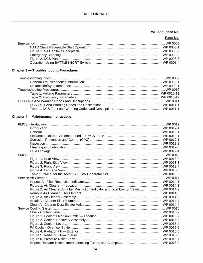
Troubleshooting Index ............................................................................................................................ WP 0009 General Troubleshooting Information.....................................................................................WP 0009-1 Malfunction/Symptom Index ...................................................................................................WP 0009-1 Troubleshooting Procedures ................................................................................................................. WP 0010 Table 1. Voltage Parameters................................................................................................WP 0010-11 Table 2. Frequency Parameters ...........................................................................................WP 0010-12
DCS Fault And Warning Codes And Descriptions ................................................................................. WP 0011 DCS Fault And Warning Codes and Descriptions..................................................................WP 0011-1 Table 1. DCS Fault and Warning Codes and Descriptions ....................................................WP 0011-1
Chapter 4 —Maintenance Instructions
PMCS Introduction.................................................................................................................................. WP 0012 Introduction .............................................................................................................................WP 0012-1 General ...................................................................................................................................WP 0012-1 Explanation of the Columns Found in PMCS Table...............................................................WP 0012-1 Corrosion Prevention and Control (CPC) ...............................................................................WP 0012-1 Inspection ...............................................................................................................................WP 0012-2 Cleaning and Lubrication........................................................................................................WP 0012-3 Fluid Leakage .........................................................................................................................WP 0012-4
PMCS ................................................................................................................................................... WP 0013 Figure 1. Rear View................................................................................................................WP 0013-2 Figure 2. Right-Side View.......................................................................................................WP 0013-3 Figure 3. Front View ...............................................................................................................WP 0013-4 Figure 4. Left-Side View .........................................................................................................WP 0013-5 Table 1. PMCS for the AMMPS 15 kW Generator Set...........................................................WP 0013-6
Service Air Cleaner................................................................................................................................. WP 0014 Inspect Air Filter Restriction Indicator.....................................................................................WP 0014-1 Figure 1. Air Cleaner — Location ...........................................................................................WP 0014-1 Figure 2. Air Cleaner/Air Filter Restriction Indicator and Dust Ejector Valve .........................WP 0014-2 Remove Air Cleaner Filter Element ........................................................................................WP 0014-3 Figure 3. Air Cleaner Assembly..............................................................................................WP 0014-3 Install Air Cleaner Filter Element ............................................................................................WP 0014-4 Clean Air Cleaner Dust Ejector Valve ....................................................................................WP 0014-4
Service Cooling System ......................................................................................................................... WP 0015 Check Coolant Level ..............................................................................................................WP 0015-2 Figure 1. Coolant Overflow Bottle — Location .......................................................................WP 0015-2 Figure 2. Coolant Recovery Assembly ...................................................................................WP 0015-3 Figure 3. Coolant Level ..........................................................................................................WP 0015-4 Fill Coolant Overflow Bottle ....................................................................................................WP 0015-5 Figure 4. Radiator Fill — Exterior ...........................................................................................WP 0015-5 Figure 5. Radiator Fill — Interior ............................................................................................WP 0015-6 Figure 6. Pressure Relief Valve..............................................................................................WP 0015-7 Inspect Radiator Hoses, Interconnecting Tubes, and Clamps ...............................................WP 0015-9
TM 9-6115-751-10
vii
WP Sequence No.
Page No.
Figure 7. Cooling System Hoses, Interconnecting Tubes, and Clamps — Left Side............. WP 0015-9 Figure 8. Cooling System Hoses, Interconnecting Tubes, and Clamps — Right Side ........ WP 0015-10 Service Fuel System............................................................................................................................... WP 0016 Check Fuel Level.................................................................................................................... WP 0016-2 Figure 1. Fuel Fill — Location................................................................................................. WP 0016-2 Figure 2. Fuel Filler ................................................................................................................ WP 0016-3 Fill Fuel Tank .......................................................................................................................... WP 0016-4 Service Fuel Filter/Water Separator ....................................................................................... WP 0016-5 Figure 3. Fuel Filter/Water Separator..................................................................................... WP 0016-5 Service Engine Oil .................................................................................................................................. WP 0017 Check Oil Level of Engine Not In-Service .............................................................................. WP 0017-1 Figure 1. Oil Service — Location............................................................................................WP 0017-2 Check Oil Level of Operating Engine ..................................................................................... WP 0017-3 Collect Engine Oil Sample...................................................................................................... WP 0017-4 Add Engine Oil........................................................................................................................ WP 0017-5
Chapter 5 — Supporting Information
References ............................................................................................................................................ WP 0018 Scope...................................................................................................................................... WP 0018-1 Field Manuals ......................................................................................................................... WP 0018-1 Forms...................................................................................................................................... WP 0018-1 Technical Manuals.................................................................................................................. WP 0018-2 Miscellaneous Documents...................................................................................................... WP 0018-2 Components of End Item (COEI) And Basic Issue Items (BII)............................................................... WP 0019 Introduction............................................................................................................................. WP 0019-1 Scope...................................................................................................................................... WP 0019-1 General ................................................................................................................................... WP 0019-1 Explanation of Columns in the COEI List and BII List ............................................................WP 0019-1 Figure 1. Basic Issue Items (BII) ............................................................................................ WP 0019-2 Table 1. Basic Issue Items (BII).............................................................................................. WP 0019-3 Additional Authorization List (AAL) ......................................................................................................... WP 0020 Introduction............................................................................................................................. WP 0020-1 Scope...................................................................................................................................... WP 0020-1 General ................................................................................................................................... WP 0020-1 Explanation of Columns in the AAL........................................................................................WP 0020-1 Table 1. Additional Authorizations List ................................................................................... WP 0020-1 Expendable And Durable Items List ....................................................................................................... WP 0021 Scope...................................................................................................................................... WP 0021-1 Explanation of Columns in the Expendable/Durable Items List ............................................. WP 0021-1 Table 1. Expendable and Durable Items ................................................................................ WP 0021-1
Glossary Alphabetical Index

TM 9-6115-751-10
viii
HOW TO USE THIS MANUAL
This manual contains operator instructions for the AMMPS 15 kilowatt (kW) generator sets, Mobile Electric Power (MEP)-1050 (50/60 Hertz (Hz)) and MEP-1051 (400 Hz).
This operator’s manual is part of a family of manuals that includes a field and sustainment maintenance manual (TM 9-6115-751-24&P) with Repair Parts and Special Tools List (RPSTL), an operator and field maintainer manual with Repair Parts and Special Tools List (RPSTL) for Power Units (PU) and Power Plants (PP) (TM 9-6115-757-13&P), and a National Maintenance Work Requirement (NMWR) Maintenance Manual (NMWR 9-6115-751).
NOTE
Throughout the family of manuals, directional orientation in relation to the generator set is described from the point of view of the operator facing the operator’s controls looking out over the generator set. From this perspective, the end of the generator set containing the operator’s controls will be referred to as the rear of the generator set.
Manual Overview
This operator’s manual provides operating procedures, troubleshooting, PMCS, maintenance, and supporting information required to operate and maintain the AMMPS 15 kW generator sets. Listed below are some of the features included in this TM to help locate and use the provided information.
WORK PACKAGES (WPs)
This TM has been organized using the WP concept. Each chapter contains a series of WPs rather than sections and paragraphs. Each WP is designed to stand alone as a complete information module. If you keep your section(s) of this TM in a loose-leaf binder, you will be able to remove just the WP needed to complete a specific task.
Each WP is numbered using a four-digit number beginning with WP 0001. WPs are numbered sequentially throughout the TM (e.g. WP 0022, WP 0023, etc.). The Table of Contents lists each chapter and WP title, as well as all figures and tables contained within each WP. Figures and tables are numbered sequentially within each WP.
The WP number is located at the top right of each page. It is also located at the bottom of the page with the WP page number included (0001-1 would be page 1 of the General Information WP (WP 0001, General Information).
Each WP starts on a right-hand page. This is done so you can remove a single WP from the paper TM if needed for a task. Blank pages are assigned a number, but it appears on the preceding or following page. For example, if page 0001-10 of a WP is blank, page 0001-9 will have the number 0001-9/10 blank; or if page 0001-1 of a WP is blank, page 0001-2 will have the number 0001-1 blank/2.
Each WP containing step-by-step maintenance or troubleshooting procedures will end with the words END OF TASK, and each WP ends with the statement END OF WORK PACKAGE. Think of each WP as a small, stand-alone TM.
Typographical conventions are as follows:
[Unload] indicates a soft key or a switch.
[Previous] + [Next] indicates two simultaneous key presses.
[ + ] [ - ] indicates two sequential key presses.
TM 9-6115-751-10
ix
References to equipment placarding or data and description plates (WP 0005, Operation Under Usual Conditions) are printed as they appear on the equipment whenever possible. On-screen text is shown in brackets in the manual (i.e. [Ready to Crank]).
Warnings, Cautions, and Notes Definitions
Warning, caution, and note headings, chapter titles, and paragraph headings are printed in bold type. Multiple warning, caution, or note paragraphs may appear above a procedure, task, or step with one warning, caution, or note heading. Prior to starting a WP, all warnings included in the WP should be reviewed, understood, and followed. Review the materials/parts in the initial setup of the WP for any hazardous materials used during maintenance of the equipment. Then refer to the detailed warnings for hazardous materials in the Warning Summary. Make sure to read all warnings within referenced WP that are required to complete tasks.
WARNING
Warning highlights an essential operating or maintenance procedure, practice, condition, statement, etc. which, if not strictly observed, could result in injury to, or death of, personnel or long term health hazards.
CAUTION
Caution highlights an essential operating or maintenance procedure, practice, condition, statement, etc., which, if not strictly observed, could result in damage to, or destruction of, equipment or loss of mission effectiveness.
NOTE
Note highlights an essential operating or maintenance procedure, condition, or statement.
TECHNICAL MANUAL CONTENT
A table of contents is provided for a quick reference to the chapters and WPs. Become familiar with it in order to quickly locate the information needed. This TM is divided into the following chapters:
CHAPTER 1 provides general information including characteristics, capabilities, features, and theory of operation for the AMMPS and its major components. The General Information WP (WP 0001, General Information) contains a nomenclature cross-reference list, a list of abbreviations and acronyms used in this TM, general information about this manual, and the related forms and records. Instructions are provided for making equipment improvement and recommendations. Coverage includes a reference to the manual that contains instructions on destruction of materiel to prevent enemy use.
CHAPTER 2 provides the detailed instructions for safe operation of the AMMPS. It includes description and use for AMMPS controls (WP 0004, Description and Use of Operator Controls and Indicators), as well as operations under usual (WP 0005, Operation Under Usual Conditions) and unusual conditions (WP 0007, Operation Under Unusual Conditions).
CHAPTER 3 provides an operator troubleshooting malfunction/symptom index (WP 0009, Troubleshooting Index) and troubleshooting procedures (WP 0010, Troubleshooting Procedures) for AMMPS. Most operator controls and indicators are contained in a Digital Control System (DCS). All DCS fault and warning codes are listed and described in Chapter 3 (WP 0011, DCS Fault & Warning Codes and Descriptions). The DCS Fault & Warning Codes and Descriptions WP provides examples of fault and warning screens exactly as the text will appear on the DCS display.
CHAPTER 4 provides operator PMCS (WP 0013, PMCS) procedures necessary to service and maintain the AMMPS 15 kW generator set. Operator maintenance tasks are also provided.

TM 9-6115-751-10
x
CHAPTER 5 includes supporting information for the AMMPS generator set, which includes a list all the FM, forms, TM, and miscellaneous publications referenced in the TM (WP 0018, References). Chapter 5 also provides Components of End Item (COEI) and Basic Issue Items (BII) lists (WP 0019, COEI and BII Lists) to help inventory items for safe and efficient operation of the AMMPS. It also contains Additional Authorization List (AAL) (WP 0020, AAL) and a list of expendable and durable items (WP 0021, Expendable and Durable Items List) needed to operate and maintain the AMMPS generator set.
Appendices and Rear Matter include a Glossary and Department of the Army (DA) Form 2028, Recommended Changes to Publications and Blank Forms. The Glossary contains the list of terms and definitions which are uncommon and not identified within the manual or within a standard dictionary. The DA Form 2028 is the document to be submitted to correct errors found in the manual or to make recommended changes that will improve the manual.

TM 9-6115-751-10
CHAPTER 1 GENERAL INFORMATION, EQUIPMENT DESCRIPTION, AND
THEORY OF OPERATION FOR
AMMPS 15KW GENERATOR SET

TM 9-6115-751-10
CHAPTER 1
GENERAL INFORMATION, EQUIPMENT DESCRIPTION, AND THEORY OF OPERATION
WORK PACKAGE INDEX
Title WP Sequence No.
GENERAL INFORMATION.................................................................................................................................. 0001
EQUIPMENT DESCRIPTION AND DATA........................................................................................................... 0002
THEORY OF OPERATION.................................................................................................................................. 0003
TM 9-6115-751-10 0001
0001-1
OPERATOR MAINTENANCE
AMMPS 15KW GENERATOR SET
GENERAL INFORMATION
SCOPE
This operator maintenance TM contains instructions for operating and maintaining the AMMPS 15 kW generator set.
Type of Manual
Operator and crew maintenance.
Model Number(s) and Equipment Name(s)
AMMPS 15 kW 50/60 and 400 hertz (Hz) generator set, skid mounted (Table 1):
Table 1. Model Numbers and Equipment Names.
MODEL HERTZ NSN MEP-1050 50/60 6115-01-561-7634 MEP-1051 400 6115-01-561-7674
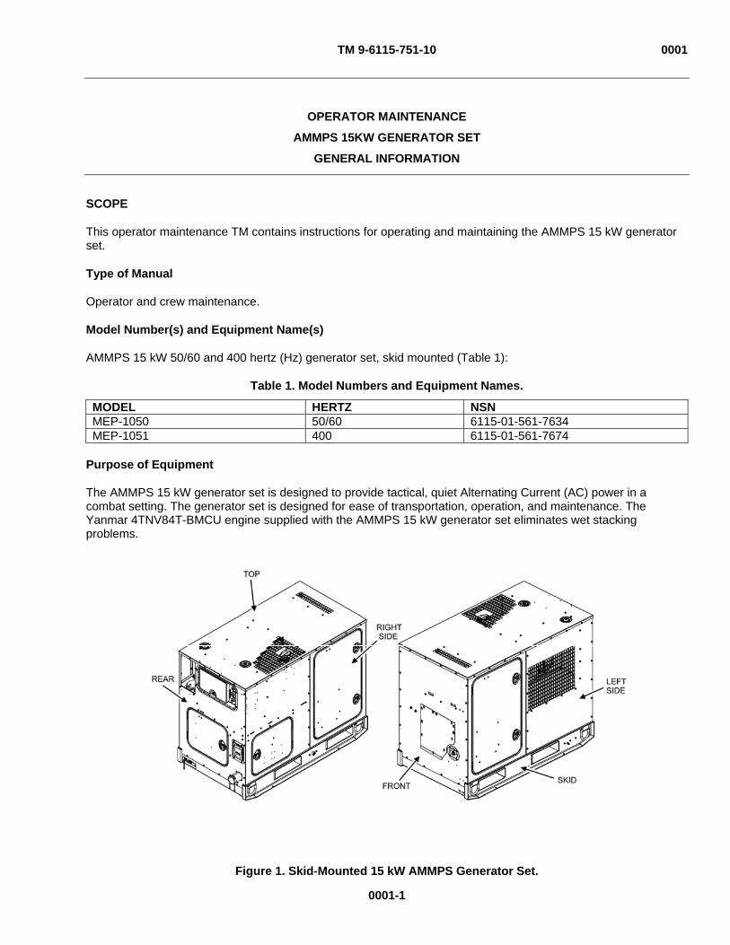
Purpose of Equipment
The AMMPS 15 kW generator set is designed to provide tactical, quiet Alternating Current (AC) power in a combat setting. The generator set is designed for ease of transportation, operation, and maintenance. The Yanmar 4TNV84T-BMCU engine supplied with the AMMPS 15 kW generator set eliminates wet stacking problems.
Figure 1. Skid-Mounted 15 kW AMMPS Generator Set.

TM 9-6115-751-10 0001
0001-2
MAINTENANCE FORMS, RECORDS, AND REPORTS
(1) (Army). Department of the Army forms and procedures used for equipment maintenance will be those prescribed by (as applicable) DA PAM 750-8, The Army Maintenance Management System (TAMMS) Users Manual; DA PAM 738-751, Functional Users Manual for the Army Maintenance Management System — Aviation (TAMMS-A); or AR 700-138, Army Logistics Readiness and Sustainability.
(2) (Marine Corps). Maintenance forms and records used by Marine Corps personnel are prescribed in TM 4700-15/1.
(3) (Air Force). Maintenance forms and records used by Air Force personnel are prescribed in AFI 21-101 and the applicable TO 00-20, Series of Technical Orders.
(4) (Navy). Navy users should refer to their service peculiar directives to determine applicable maintenance forms and records to be used.
REPORTING EQUIPMENT IMPROVEMENT RECOMMENDATIONS (EIR)
(1) (Army). If your equipment needs improvement, let us know. Send us an EIR. You, the user, are the only one who can tell us what you don’t like about your equipment. Let us know why you don’t like the design or performance. If you have Internet access, the easiest and fastest way to report problems or suggestions is to follow the instructions and links below:
If you have a user’s account, you can submit the PQDR for ALL CECOM (B16) Warranty, EIR, and PQDRs (including those B16 Aviation related) through the Navy’s Web Product Quality Deficiency Reporting (PQDR) site, http://www.nslcptsmh.csd.disa.mil/webpqdr/webpqdr.htm. If you do not, either go to EZPQDR, http://www.nslcptsmh.csd.disa.mil/webpqdr/files/ezpqdr.htm and input your PQDR there, or establish a new account. New accounts can be established at the following address: http://www.nslcptsmh.csd.disa.mil/accessforms/uarform.htm.
CECOM (B16) aviation PQDRs will not go to AMCOMs Joint Deficiency Reporting System (JDRS). If AMCOM should get a CECOM aviation PQDR, they will redirect it to the CECOM PQDR Team.
Use the PQDR for Warranties, EIRs, and PQDRs. There is a block on the PQDR that can be clicked if it is a Warranty. The originator can still put in the description that they want this investigated as an EIR and then enter what the issue is.
You may also submit your SF 368 (Product Quality Deficiency Report) via email ([email protected]), facsimile (732-532-2929), or regular mail (call 732-532-8843 for the current mailing address).
We will send you a reply.
(2) (Air Force). Air Force personnel are encouraged to submit EIRs IAW Air Force Regulation (AFR) 900-4.
(3) (Navy). Navy personnel are encouraged to submit EIRs through their local Beneficial Suggestion Program.
(4) (Marine Corps). QDR shall be reported on SF 368 IAW MCO P4855.10, Product Quality Deficiency Report Manual. Submit to Commanding General, Marine Corps Logistics Base (Code 850), Albany, Georgia 31704-5000. A reply will be furnished to you.
CORROSION PREVENTION AND CONTROL (CPC)
Corrosion Prevention and Control (CPC) of Army materiel is a continuing concern. It is important that any corrosion problems with this item be reported so that the problem can be corrected and improvements can be made to prevent the problem in future items.
Corrosion specifically occurs with metals. It is an electrochemical process that causes the degradation of metals. It is commonly caused by exposure to moisture, acids, bases, or salts. An example is the rusting of iron. Corrosion damage in metals can be seen, depending on the metal, as tarnishing, pitting, fogging, surface residue, and/or cracking.

TM 9-6115-751-10 0001
0001-3
Plastics, composites, and rubbers can also degrade. Degradation is caused by thermal (heat), oxidation (oxygen), solvation (solvents), or photolytic (light, typically Ultraviolet (UV)) processes. The most common exposures are excessive heat or light. Damage from these processes will appear as cracking, softening, swelling, and/or breaking. SF 368, Product Quality Deficiency Report, should be submitted to the address specified in DA PAM 750-8, The Army Maintenance Management System (TAMMS) Users Manual.
For aircraft TMs, this information shall include a reference to TM 1-1500-344-23, volumes 1 through 4 (Cleaning and Corrosion Control).
OZONE-DEPLETING SUBSTANCES (ODS)
The use of Class 1 Ozone-Depleting Substances (ODS) for new acquisitions has been curtailed by Section 326 of the National Defense Authorization Act of Fiscal Year 1993 (Public Law 102, 484) and related Army policy. ODS are listed in Title VI of the Clean Air Act. For systems procured and fielded prior to the effectiveness of the above law (June 1993) that use a Class 1 ODS, a listing of those substances required to operate and maintain the system shall be included in the TM. This requirement applies to any system procured or fielded after June 1993 that requires the use of a Class 1 ODS, where the use of the ODS has been properly documented and waived. The procuring activity will provide a list of Class 1 ODS on request.
DESTRUCTION OF ARMY MATERIEL TO PREVENT ENEMY USE
Destruction of Army electronics materiel to prevent enemy use shall be IAW TM 750-244-2.
Destruction of Air Force materiel to prevent enemy use shall be IAW AFI 33-201.
Destruction of Navy materiel to prevent enemy use shall be IAW Navy direction.
Destruction of Marine Corps materiel to prevent enemy use shall be IAW MC direction.
DEMOLITION OF MARINE CORPS MATERIEL TO PREVENT ENEMY USE
Demolition to Render the Generator Set Inoperative
1. When capture or abandonment of the generator set to an enemy is imminent, the responsible unit commander must make the decision to either destroy or render the equipment inoperative.
2. Based on this decision, orders are issued which cover the desired extent of destruction.
a. Operators should be thoroughly familiar with all methods of destruction without referencing any particular manual.
b. Demolition of the generator set can be accomplished by explosives, fire, or tools such as a sledge hammer, pick, or ax. Demolition can also be accomplished by misuse.
3. The method used will depend on the time available and the availability of these materials in the vicinity of the generator set.
4. Demolition by mechanical means:
a. Use hammer, pick, ax, or any other available tool to destroy vital engine and control parts.
b. Control box, fuel injection lines, and the radiator should be smashed, engine and control box wires pulled and cut, and any other external engine components (fuel filter, alternator) should be damaged enough to make them inoperable.
5. Demolition by misuse:
a. Drain diesel generator crankcase oil.
b. Block diesel generator engine air supply ports.
c. Start diesel generator engine and allow it to operate until it fails.

TM 9-6115-751-10 0001
0001-4
d. Pour sand, dirt, or other available abrasive compound in all exposed surfaces and access ports of the diesel engine and generator.
e. Drain engine coolant.
6. Demolition by burning: Complete as much mechanical damage as possible, and then saturate unit with combustible fuel and ignite.
7. Demolition by explosives: Place explosive charges in priority order (Table 2).
Table 2. Demolition Priority Levels.
PRIORITY LEVEL COMPONENT EXPLOSIVE CHARGE REQUIRED
1 Generator Engine 1 pound (lb) 2 Control Box 1 lb 3 Generator Housing 1 lb 4 Housing/Structure 2 lb
PREPARATION FOR STORAGE OR SHIPMENT
Administrative storage of equipment issued to and used by Army activities will have Preventive Maintenance Checks and Services (PMCS) performed before storing. When removing the equipment from administrative storage, the PMCS checks should be performed to assure operational readiness.
WARRANTY INFORMATION
The AMMPS 15 kW generator set is warranted for 1800 hours (hr) of operation or 36 months, whichever occurs first. The warranty starts on the date the equipment is accepted in the “Wide Area Work Flow” system. This warranty includes repair or replacement of any items that prove to be nonconforming and/or defective within the warranty period. Report all defects to your supervisor, who will take appropriate action.
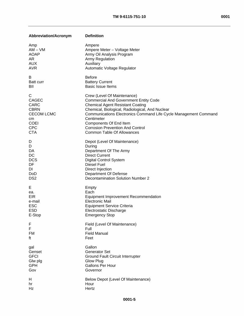
LIST OF ABBREVIATIONS/ACRONYMS
Acronyms and abbreviations used in this TM are provided and defined below.
Abbreviation/Acronym Definition
- Negative % Percent + Positive ± Plus or minus
Up Down Left Right
°C Degrees Celsius °F Degrees Fahrenheit A After AAC Ampere Alternating Current AAL Additional Authorization List AC Alternating Current ADC Amperes Direct Current AFI Air Force Instruction AFR Air Force Regulation AFTO Air Force Technical Order AH Ampere Hour AMMPS Advanced Medium Mobile Power Sources
TM 9-6115-751-10 0001
0001-5
Abbreviation/Acronym Definition
Amp Ampere AM – VM Ampere Meter – Voltage Meter AOAP Army Oil Analysis Program AR Army Regulation AUX Auxiliary AVR Automatic Voltage Regulator B Before Batt curr Battery Current BII Basic Issue Items C Crew (Level Of Maintenance) CAGEC Commercial And Government Entity Code CARC Chemical Agent Resistant Coating CBRN Chemical, Biological, Radiological, And Nuclear CECOM LCMC Communications Electronics Command Life Cycle Management Command cm Centimeter COEI Components Of End Item CPC Corrosion Prevention And Control CTA Common Table Of Allowances D Depot (Level Of Maintenance) D During DA Department Of The Army DC Direct Current DCS Digital Control System DF Diesel Fuel DI Direct Injection DoD Department Of Defense DS2 Decontamination Solution Number 2 E Empty ea. Each EIR Equipment Improvement Recommendation e-mail Electronic Mail ESC Equipment Service Criteria ESD Electrostatic Discharge E-Stop Emergency Stop F Field (Level Of Maintenance) F Full FM Field Manual ft Feet gal Gallon Genset Generator Set GFCI Ground Fault Circuit Interrupter Glw plg Glow Plug GPH Gallons Per Hour Gov Governor H Below Depot (Level Of Maintenance) hr Hour Hz Hertz
TM 9-6115-751-10 0001
0001-6
Abbreviation/Acronym Definition
IAW In Accordance With IBM International Business Machine ID Identification in Inch in3 Cubic inches IUID Individual Unit Identification JDRS Joint Deficiency Reporting System JP Jet Propulsion Fuel JTA Joint Table Of Allowances kg Kilogram kPa KiloPascal kVAR Kilovolt-Ampere Reactive kW Kilowatt L Liter lb Pound L/Hr Liters per hour LCD Liquid Crystal Display L-L Line-To-Line L-N Line-To-Neutral LRU Line Replaceable Unit m Meter mA MilliAmpere MCO Marine Corps Order MEP Mobile Electric Power MG Mobile Generator min Minute mm Millimeter MSDS Material Safety Data Sheets MWO Modification Work Order MTOE Modified Table Of Organization And Equipment N/A Not Applicable NATO North Atlantic Treaty Organization NBC Nuclear Biological Chemical NEMA National Electrical Manufacturers Association NMWR National Maintenance Work Requirement No. Number NSN National Stock Number ODS Ozone-Depleting Substances OEM Original Equipment Manufacture OSHA Occupational Safety And Health Act PAM Pamphlet PC Personal Computer PMG Permanent Magnet Generator P/N Part Number PDA Personal Data Assistant PMCS Preventive Maintenance Checks And Services
TM 9-6115-751-10 0001
0001-7
Abbreviation/Acronym Definition
PP Power Plant PQDR Product Quality Deficiency Report Press Pressure psi Pounds per square inch PU Power Unit QDR Quality Deficiency Report qt. Quart Qty. Recm. Quantity Recommended Qty. Rqr. Quantity Required rpm Revolutions per minute RPSTL Repair Parts And Special Tools List sec Second SF Standard Form SOP Standard Operating Procedure STB Super-Tropical Bleach TAMMS The Army Maintenance Management System TAMMS-A The Army Maintenance Management System — Aviation TBD To Be Determined TDA Tactical Decision Aid Temp Temperature TM Technical Manual TOE Table Of Organization And Equipment TO Technical Order U/I Unit Of Issue USB Universal Serial Bus UV Ultraviolet V Volt VAC Volts Alternating Current VDC Volts Direct Current WP Work Package Wtr Winterization
TM 9-6115-751-10 0001
0001-8
SAFETY, CARE, AND HANDLING
ESD: The AMMPS 15 kW generator set DCS contains printed circuit boards and control cards requiring special handling to protect them from ESD when being serviced. The operator does not need to use special handling for operation of the AMMPS 15 kW generator set.
This TM describes physical and chemical processes that may require the use of chemicals, solvents, paints, or other commercially available materials. Users of the TM should obtain the Material Safety Data Sheets (MSDS) (OSHA Form 20 or equivalent) from the manufacturers or suppliers of materials to be used. Users must be completely familiar with manufacturer/supplier information and adhere to their procedures, recommendations, warnings, and cautions for safe use, handling, storage, and disposal of these materials.
END OF WORK PACKAGE

TM 9-6115-751-10 0002
OPERATOR MAINTENANCE
AMMPS 15KW GENERATOR SET
EQUIPMENT DESCRIPTION AND DATA
EQUIPMENT CHARACTERISTICS, CAPABILITIES, AND FEATURES
The AMMPS 15 kW generator set (Figure 1) is a fully-enclosed, self-contained, skid-mounted mobile unit. The generator set consists of six major assemblies; engine assembly, internal fuel assembly, external fuel assembly (not shown), AC generator assembly, Digital Control System (DCS), and output box assembly. An optional winterization kit is available for installation in cold weather climates.
The AMMPS 15 kW generator set is designed to accommodate the continuing proliferation of electronics (computers, Personal Data Assistants (PDA), etc.), life support systems, and global communications necessary in today’s battlefield that require a continuous, uninterrupted flow of electricity to accommodate all tactical situations.
LOCATION AND DESCRIPTION OF MAJOR COMPONENTS
Figure 1. AMMPS 15 kW Generator Set with Doors Closed.
HOUSING
A steel housing consisting of several individual body panels encloses the AMMPS 15 kW generator set and protects it from the environment. The housing provides acoustical protection, entry access to generator set assemblies, control of air flow over internal surfaces, and mounting for generator set components.
0002-1

TM 9-6115-751-10 0002
The steel housing is durable enough so that no damage should occur within normal usage. The housing design prevents the invasion of wind-driven rain, snow, and sand to the interior of the units through the design and placement of the louver and a rain cap. The Chemical Agent Resistant Coating (CARC) paint, polyurethane coating on circuit boards, sealed connectors, and immersion-proof fan motor housing provide additional protection against moisture and condensation damage.
Self-supporting hinged doors allow easy interior access for scheduled service and preventive maintenance. Individual body panels are removable to allow additional access for replacement and service of major components.
Body Panels
All body panels are connected using corrosion-resistant captive nuts. All seals are interference fit to the housing panels.
Figure 2. Rear and Right-Side View with Doors Open.
Top Panel (Figure 2, Item 2). The top panel shields components from the elements.
Rear Panel (Figure 2, Item 9). Located at the rear of the generator set, the rear panel contains the DCS access door (Figure 2, Item 1), DCS (Figure 2, Item 11), rear access door (Figure 2, Item 10), convenience receptacle (Figure 2, Item 7), entrance for load cables (Figure 2, Item 8), and fuel fill (Figure 2, Item 12).
Right-Side Panel (Figure 2, Item 5). Located on the right side of the generator set, the right-side panel contains the right-side access door (Figure 2, Item 3) and output box door (Figure 2, Item 6).
Storage Box (Figure 2, Item 4). An accessory box stenciled Storage Box has been installed on the rear of the right-side access door (Figure 2, Item 3) to provide space for the paralleling cable, grounding rod connecting hardware, and auxiliary fuel line.
0002-2
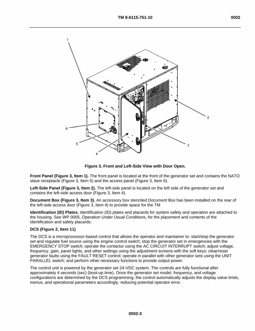
TM 9-6115-751-10 0002
Figure 3. Front and Left-Side View with Door Open.
Front Panel (Figure 3, Item 1). The front panel is located at the front of the generator set and contains the NATO slave receptacle (Figure 3, Item 5) and the access panel (Figure 3, Item 6).
Left-Side Panel (Figure 3, Item 2). The left-side panel is located on the left side of the generator set and contains the left-side access door (Figure 3, Item 4).
Document Box (Figure 3, Item 3). An accessory box stenciled Document Box has been installed on the rear of the left-side access door (Figure 3, Item 4) to provide space for the TM
Identification (ID) Plates. Identification (ID) plates and placards for system safety and operation are attached to the housing. See WP 0005, Operation Under Usual Conditions, for the placement and contents of the identification and safety placards.
DCS (Figure 2, Item 11)
The DCS is a microprocessor-based control that allows the operator and maintainer to: start/stop the generator set and regulate fuel source using the engine control switch; stop the generator set in emergencies with the EMERGENCY STOP switch; operate the contactor using the AC CIRCUIT INTERRUPT switch; adjust voltage, frequency, gain, panel lights, and other settings using the adjustment screens with the soft keys; clear/reset generator faults using the FAULT RESET control; operate in parallel with other generator sets using the UNIT PARALLEL switch; and perform other necessary functions to provide output power.
The control unit is powered by the generator set 24-VDC system. The controls are fully functional after approximately 4 seconds (sec) (boot-up time). Once the generator set model, frequency, and voltage configurations are determined by the DCS programming, the control automatically adjusts the display value limits, menus, and operational parameters accordingly, reducing potential operator error.
0002-3

TM 9-6115-751-10 0002
The AMMPS 15 kW generator sets provide limited remote operation capabilities through interface with an International Business Machine (IBM)-compatible Personal Computer (PC). The operational status of the generator set can be monitored, battleshort conditions can be set and released, and emergency stop can be executed from up to a 250-foot (ft) (76.2-meters (m)) distance. Loss of signal between the remote monitoring site and the generator set does not adversely affect the generator set operation.
The DCS display is a colored Liquid Crystal Display (LCD) with a 6.5-inch (in) (165.1-millimeter (mm)) diagonal viewing area. It provides a combination of switches and LCD soft keys to allow the operator and maintainer to control the generator set.
SKID ASSEMBLY (Figure 4)
Figure 4. Skid.
The housing sits on a steel skid that extends beyond the housing walls by approximately 0.39 in (10 mm). The engine and AC generator are directly mounted to the skid with the focus toward the roll inertia axis. This improves vibration isolation. The skid is equipped with forklift pockets for transportation capability. The skid base has drains located between the fork lift pockets on each side for draining liquids from the generator set.
ENGINE ASSEMBLY
The AMMPS 15 kW generator set uses a Yanmar 4TNV84T diesel engine. The vertical, water-cooled, four-cycle Direct Injection (DI) diesel engine utilizes a four-cylinder, turbocharged process. It consists of the cylinder head and valve cover, crankcase assembly, pistons, main bearing case, and lubrication system. It is mounted to the skid toward the front panel of the generator set. See Figure 5 and Figure 6 for a breakdown of major engine components.
0002-4

TM 9-6115-751-10 0002
0002-5
NOTE
The heat shield has been removed from Figure 5 for clarity.
Figure 5. Engine Components — Left Side.
Major Engine Components/Assemblies
Major engine components/assemblies include: cylinder head and valve cover assembly, block assembly, flywheel, lubrication system, engine fuel system, cooling system, DC electrical system, and air intake and exhaust system.
Cylinder Head (Figure 5, Item 1) and Valve Cover (Figure 5, Item 2) Assembly. The cylinder head is located on the top of the block assembly (Figure 5, Item 4) and seals the upper ends of the cylinders to provide compression, protects the portion of the engine where combustion takes place, and houses the valve assembly. The valve cover is located on top of the cylinder head assembly and protects the valve assembly from contamination.
Block Assembly (Figure 5, Item 4). The block assembly houses the connecting rods, crankshaft, pistons, camshaft, and bearings.
Lubrication System. The AMMPS 15 kW generator set lubrication system is compatible with MIL-PRF-21260E preservative oil. The lubricating oil conforms to MIL-PRF-46167C and MIL-PRF-2104H.
Operators can safely check and add oil to the lubricating system while the generator set is operating or in the OFF condition. The lubrication system includes an oil-filler opening with captive cap (Figure 6, Item 2) to permit oil-filling from a standard 8-quart (qt) capacity can and a readily-accessible oil-level bayonet gage (dipstick) (Figure 6, Item 7). The dipstick (Figure 6, Item 7) is marked to ensure accurate reading of oil levels. See WP 0017, Service Engine Oil for more information.

TM 9-6115-751-10 0002
Oil Filter (Figure 6, Item 4). The oil filter is located at the intake side of the engine behind the battery-charging alternator belt. It removes impurities from the engine lubricating oil by utilizing a full-flow, spin-on disposable oil filter cartridge. The oil filter attaches to an oil cooler assembly (Figure 6, Item 3), which uses the engine cooling system to keep the oil temperature in the optimum temperature range.
Oil Drain Assembly (Figure 6, Item 5). The oil drain assembly is located between the oil pan (Figure 6, Item 8) and the unit skid. It allows the engine oil to be easily drained into a remote catch basin using a ball valve (Figure 6, Item 6).
Figure 6. Engine Components — Right Side.
Fuel Injection System. Once fuel has passed through the fuel filter/water separator (Figure 8, Item 1), the fuel passes through the fuel injection pump (Figure 5, Item 5). The fuel injection pump divides equal amounts of fuel for each of the engine’s four cylinders. The fuel then passes through the valve cover using high-pressure injector lines (Figure 6, Item 1) to the fuel injector in each cylinder. The injector sprays the fuel at high pressure into the cylinder where it is burned.
Flywheel (Figure 6, Item 9). The flywheel connects the engine to the AC generator to transmit rotational mechanical energy for the production of electricity.
0002-6
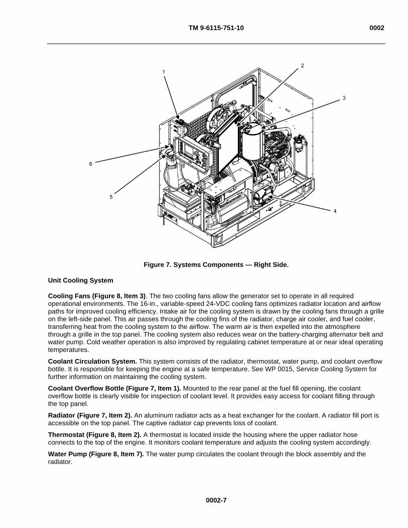
TM 9-6115-751-10 0002
Figure 7. Systems Components — Right Side.
Unit Cooling System
Cooling Fans (Figure 8, Item 3). The two cooling fans allow the generator set to operate in all required operational environments. The 16-in., variable-speed 24-VDC cooling fans optimizes radiator location and airflow paths for improved cooling efficiency. Intake air for the cooling system is drawn by the cooling fans through a grille on the left-side panel. This air passes through the cooling fins of the radiator, charge air cooler, and fuel cooler, transferring heat from the cooling system to the airflow. The warm air is then expelled into the atmosphere through a grille in the top panel. The cooling system also reduces wear on the battery-charging alternator belt and water pump. Cold weather operation is also improved by regulating cabinet temperature at or near ideal operating temperatures.
Coolant Circulation System. This system consists of the radiator, thermostat, water pump, and coolant overflow bottle. It is responsible for keeping the engine at a safe temperature. See WP 0015, Service Cooling System for further information on maintaining the cooling system.
Coolant Overflow Bottle (Figure 7, Item 1). Mounted to the rear panel at the fuel fill opening, the coolant overflow bottle is clearly visible for inspection of coolant level. It provides easy access for coolant filling through the top panel.
Radiator (Figure 7, Item 2). An aluminum radiator acts as a heat exchanger for the coolant. A radiator fill port is accessible on the top panel. The captive radiator cap prevents loss of coolant.
Thermostat (Figure 8, Item 2). A thermostat is located inside the housing where the upper radiator hose connects to the top of the engine. It monitors coolant temperature and adjusts the cooling system accordingly.
Water Pump (Figure 8, Item 7). The water pump circulates the coolant through the block assembly and the radiator.
0002-7
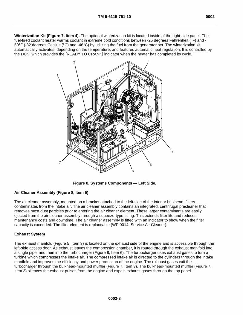
TM 9-6115-751-10 0002
Winterization Kit (Figure 7, Item 4). The optional winterization kit is located inside of the right-side panel. The fuel-fired coolant heater warms coolant in extreme cold conditions between -25 degrees Fahrenheit (°F) and -50°F (-32 degrees Celsius (°C) and -46°C) by utilizing the fuel from the generator set. The winterization kit automatically activates, depending on the temperature, and features automatic heat regulation. It is controlled by the DCS, which provides the [READY TO CRANK] indicator when the heater has completed its cycle.
Figure 8. Systems Components — Left Side.
Air Cleaner Assembly (Figure 8, Item 5)
The air cleaner assembly, mounted on a bracket attached to the left-side of the interior bulkhead, filters contaminates from the intake air. The air cleaner assembly contains an integrated, centrifugal precleaner that removes most dust particles prior to entering the air cleaner element. These larger contaminants are easily ejected from the air cleaner assembly through a squeeze-type fitting. This extends filter life and reduces maintenance costs and downtime. The air cleaner assembly is fitted with an indicator to show when the filter capacity is exceeded. The filter element is replaceable (WP 0014, Service Air Cleaner).
Exhaust System
The exhaust manifold (Figure 5, Item 3) is located on the exhaust side of the engine and is accessible through the left-side access door. As exhaust leaves the compression chamber, it is routed through the exhaust manifold into a single pipe, and then into the turbocharger (Figure 8, Item 6). The turbocharger uses exhaust gases to turn a turbine which compresses the intake air. The compressed intake air is directed to the cylinders through the intake manifold and improves the efficiency and power production of the engine. The exhaust gases exit the turbocharger through the bulkhead-mounted muffler (Figure 7, Item 3). The bulkhead-mounted muffler (Figure 7, Item 3) silences the exhaust pulses from the engine and expels exhaust gases through the top panel.
0002-8
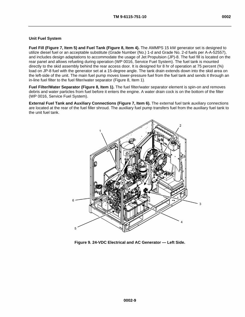
TM 9-6115-751-10 0002
Unit Fuel System
Fuel Fill (Figure 7, Item 5) and Fuel Tank (Figure 8, Item 4). The AMMPS 15 kW generator set is designed to utilize diesel fuel or an acceptable substitute (Grade Number (No.) 1-d and Grade No. 2-d fuels per A-A-52557), and includes design adaptations to accommodate the usage of Jet Propulsion (JP)-8. The fuel fill is located on the rear panel and allows refueling during operation (WP 0016, Service Fuel System). The fuel tank is mounted directly to the skid assembly behind the rear access door. It is designed for 8 hr of operation at 75 percent (%) load on JP-8 fuel with the generator set at a 15-degree angle. The tank drain extends down into the skid area on the left-side of the unit. The main fuel pump moves lower-pressure fuel from the fuel tank and sends it through an in-line fuel filter to the fuel filter/water separator (Figure 8, Item 1).
Fuel Filter/Water Separator (Figure 8, Item 1). The fuel filter/water separator element is spin-on and removes debris and water particles from fuel before it enters the engine. A water drain cock is on the bottom of the filter (WP 0016, Service Fuel System).
External Fuel Tank and Auxiliary Connections (Figure 7, Item 6). The external fuel tank auxiliary connections are located at the rear of the fuel filler shroud. The auxiliary fuel pump transfers fuel from the auxiliary fuel tank to the unit fuel tank.
Figure 9. 24-VDC Electrical and AC Generator — Left Side.
0002-9
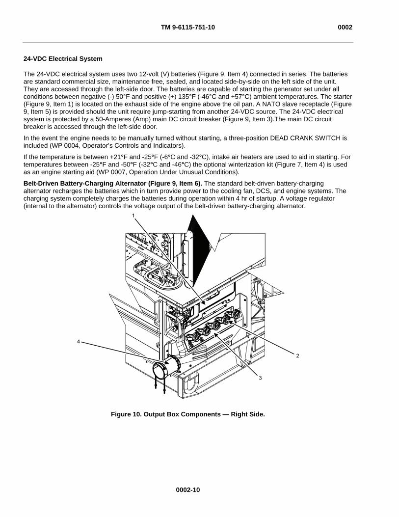
TM 9-6115-751-10 0002
24-VDC Electrical System
The 24-VDC electrical system uses two 12-volt (V) batteries (Figure 9, Item 4) connected in series. The batteries are standard commercial size, maintenance free, sealed, and located side-by-side on the left side of the unit. They are accessed through the left-side door. The batteries are capable of starting the generator set under all conditions between negative (-) 50°F and positive (+) 135°F (-46°C and +57°C) ambient temperatures. The starter (Figure 9, Item 1) is located on the exhaust side of the engine above the oil pan. A NATO slave receptacle (Figure 9, Item 5) is provided should the unit require jump-starting from another 24-VDC source. The 24-VDC electrical system is protected by a 50-Amperes (Amp) main DC circuit breaker (Figure 9, Item 3).The main DC circuit breaker is accessed through the left-side door.
In the event the engine needs to be manually turned without starting, a three-position DEAD CRANK SWITCH is included (WP 0004, Operator’s Controls and Indicators).
If the temperature is between +21°F and -25°F (-6°C and -32°C), intake air heaters are used to aid in starting. For temperatures between -25°F and -50°F (-32°C and -46°C) the optional winterization kit (Figure 7, Item 4) is used as an engine starting aid (WP 0007, Operation Under Unusual Conditions).
Belt-Driven Battery-Charging Alternator (Figure 9, Item 6). The standard belt-driven battery-charging alternator recharges the batteries which in turn provide power to the cooling fan, DCS, and engine systems. The charging system completely charges the batteries during operation within 4 hr of startup. A voltage regulator (internal to the alternator) controls the voltage output of the belt-driven battery-charging alternator.
Figure 10. Output Box Components — Right Side.
0002-10

TM 9-6115-751-10 0002
0002-11
AC GENERATOR (Figure 9, Item 2).
The AC generator converts the rotating mechanical energy from the engine into electrical energy. The electrical energy is then distributed from the output box assembly (Figure 10, Item 1) through cables that enter the output box assembly (Figure 10, Item 1) via a flexible sleeve (Figure 10, Item 4) from field equipment requiring electric power or a switch box.
The AC generator and voltage control system are drip-proof, guarded machine type and are synchronous and brushless, as specified in National Electrical Manufacturers Association (NEMA) Standard No. MG, part 33. The bearings are sealed and permanently lubricated. System leads are identified with permanent marker, and are brought out of the frame through non-abrasive bushings and holders in the output terminal board (Figure 10, Item 3). These isolate each lead and hold it securely in place.
When operating in three-phase at rated load and frequency, the AC generator can withstand, without damage, two consecutive short circuits at the load terminals of 10 sec or less in duration within a 5-min interval at less than 300% of rated output current.
OUTPUT BOX ASSEMBLY (Figure 10, Item 1)
The output box assembly is located inside the right-side panel and distributes electricity produced by the AC generator through the output terminal board (Figure 10, Item 3). The output box contains the output terminal board (Figure 10, Item 3), individual load terminals (Figure 10, Item 2), and unit relays. All relays are socket-mounted and secured with a cover. The relay will not move unless the cover is removed.
DIFFERENCES BETWEEN MODELS
The differences between models of generator set covered in this TM are as follows:
Model MEP-1050 is equipped with a 50/60 Hz generator.
Model MEP-1051 is equipped with a 400 Hz generator.
EQUIPMENT DATA
For a list of leading particulars, refer to Table 1.
Table 1. Equipment Data.
GENERATOR SET: Model Numbers:
15 kW 50/60 Hz MEP-1050 15 kW 400 Hz MEP-1051
NSN: 15 kW 50/60 Hz NSN 6115-01-561-7634 15 kW 400 Hz NSN 6115-01-561-7674
Overall Length: MEP-1050 65 in (165.1 cm) MEP-1051 65 in (165.1 cm)
Overall Width: MEP-1050 36 in (91.4 cm) MEP-1051 36 in (91.4 cm)
Overall Height: MEP-1050 53 in (134.6 cm) MEP-1051 53 in (134.6 cm)
Dry Weights (less BII): MEP-1050 1795 lb (814.2 kg) MEP-1051 1795 lb (814.2 kg)
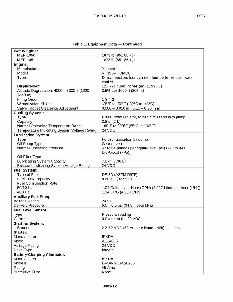
TM 9-6115-751-10 0002
0002-12
Table 1. Equipment Data — Continued.
Wet Weights: MEP-1050 1878 lb (851.85 kg) MEP-1051 1878 lb (851.85 kg)
Engine: Manufacturer Yanmar Model 4TNV84T-BMCU Type Direct injection, four cylinder, four cycle, vertical, water
cooled Displacement 121.721 cubic inches (in3) (1.995 L) Altitude Degradation, 4000 – 8000 ft (1220 – 2440 m)
3.5% per 1000 ft (305 m)
Firing Order 1-3-4-2 Winterization Kit Use -25°F to -50°F (-32°C to -46°C) Valve Tappet Clearance Adjustment 0.006 – 0.010 in. (0.15 – 0.25 mm)
Cooling System: Type Pressurized radiator, forced circulation with pump Capacity 2.8 qt (2 L) Normal Operating Temperature Range 185°F to 223°F (85°C to 106°C) Temperature Indicating System Voltage Rating 24 VDC
Lubrication System: Type Forced lubrication by pump Oil Pump Type Gear driven Normal Operating pressure 42 to 64 pounds per square inch (psi) (290 to 441
kiloPascal (kPa)) Oil Filter Type Lubricating System Capacity 7.8 qt (7.38 L) Pressure Indicating System Voltage Rating 24 VDC
Fuel System: Type of Fuel DF-2D (ASTM D975) Fuel Tank Capacity 8.60 gal (32.55 L) Fuel Consumption Rate 50/60 Hz: 1.04 Gallons per Hour (GPH) (3.937 Liters per hour (L/Hr)) 400 Hz: 1.14 GPG (4.330 L/Hr)
Auxiliary Fuel Pump: Voltage Rating 24 VDC Delivery Pressure 5.0 – 6.5 psi (34.5 – 65.5 kPa) Fuel Level Sensor: Type Pressure reading Current 3.0 amp at 6 – 32 VDC Starting System:
Batteries 2 X 12 VDC (52 Ampere Hours (AH)) in series Starter: Manufacturer ISKRA Model AZE4836 Voltage Rating 24 VDC Drive Type Integral Battery-Charging Alternator: Manufacturer ISKRA Models DRWNG 19020205 Rating 45 Amp Protective Fuse None
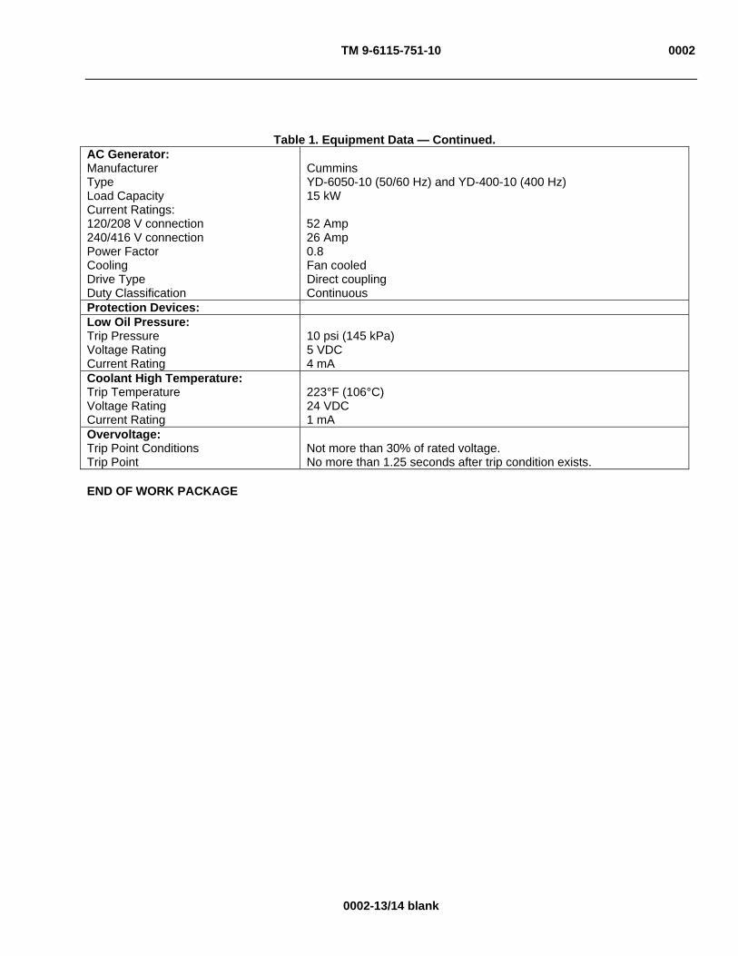
TM 9-6115-751-10 0002
0002-13/14 blank
Table 1. Equipment Data — Continued. AC Generator: Manufacturer Cummins Type YD-6050-10 (50/60 Hz) and YD-400-10 (400 Hz) Load Capacity 15 kW Current Ratings: 120/208 V connection 52 Amp 240/416 V connection 26 Amp Power Factor 0.8 Cooling Fan cooled Drive Type Direct coupling Duty Classification Continuous Protection Devices: Low Oil Pressure: Trip Pressure 10 psi (145 kPa) Voltage Rating 5 VDC Current Rating 4 mA Coolant High Temperature: Trip Temperature 223°F (106°C) Voltage Rating 24 VDC Current Rating 1 mA Overvoltage: Trip Point Conditions Not more than 30% of rated voltage. Trip Point No more than 1.25 seconds after trip condition exists.
END OF WORK PACKAGE


TM 9-6115-751-10 0003
0003-1
OPERATOR MAINTENANCE
AMMPS 15KW GENERATOR SET
THEORY OF OPERATION
SCOPE
The AMMPS 15 kW generator sets consist of two modes as follows:
MODES: I – 50/60 Hz
II – 400 Hz
The AMMPS 15 kW generator set is designed for the best possible performance focusing on areas such as reliability, maintainability, weight, dimensions, and fuel consumption.
OPERATION
The AMMPS 15 kW generator set is designed for deployment in the battlefield to provide personnel with the continuous power generation necessary for today’s fielded electronic devices and various electrical equipment demands. The AMMPS 15 kW generator set is developed to be fixed (skid mounted) or mobile (trailer mounted) giving the flexibility of movement. The generator sets are designed to accommodate parallel operation of generator sets as well additional and back-up power generation.
The housing assembly serves as the protective shell for the generator set. The housing has been designed with openings for ease of maintenance and additional acoustical protection to further silence the generator set while operating. The generator has enhancements for protection from unusual/harsh weather and to shield from debris.
The generator set is powered by a turbocharged Yanmar 4TNV84T 121.721 in3 (1.995 L) diesel engine mounted directly to the skid assembly. This particular engine has a built-in Close Crankcase Ventilation (CCV) system. The engine produces mechanical energy and interconnects with the AC generator via a rotating shaft.
The AC generator is a Cummins Power Generation (CPG) YD-6050-10 (Mode I, Model 1050 (50/60 Hz)) or a CPG YD-400-10 (Mode II, Model 1051 (400 Hz)). It is a synchronous, brushless design and was developed specifically to meet performance requirements. The AC generator receives mechanical energy from the engine and converts it to electrical energy. The electricity produced by the AC generator is transmitted to the output terminal board.
DCS
The DCS uses a menu-driven display format to control generator set operations. From the DCS, the operator, and/or maintainer can start the generator set, adjust the output voltage and frequency (Model 1070, Mode I only), operate the contactor, stop the AC generator, clear faults, and perform other functions necessary to produce power (Figure 1). The AMMPS 15 kW AMMPS generator set also provides limited remote operation capabilities through interface with an IBM-compatible PC. The operational status of the generator set can be monitored, battleshort conditions can be set and released, and emergency stop can be executed from up to a 250-ft (76.2-m) distance.
The AMMPS 15 kW generator set is capable of self-diagnostics at start up. This prognostics function monitors the protective system and will provide a warning of impending activation of protective devices. All operational data is captured every 15 min during operation. Faults and warnings are automatically captured upon operation of protective devices and stored in a Fault Log. Additionally, all maintenance prompts and actions are automatically captured and stored in a Maintenance Log.
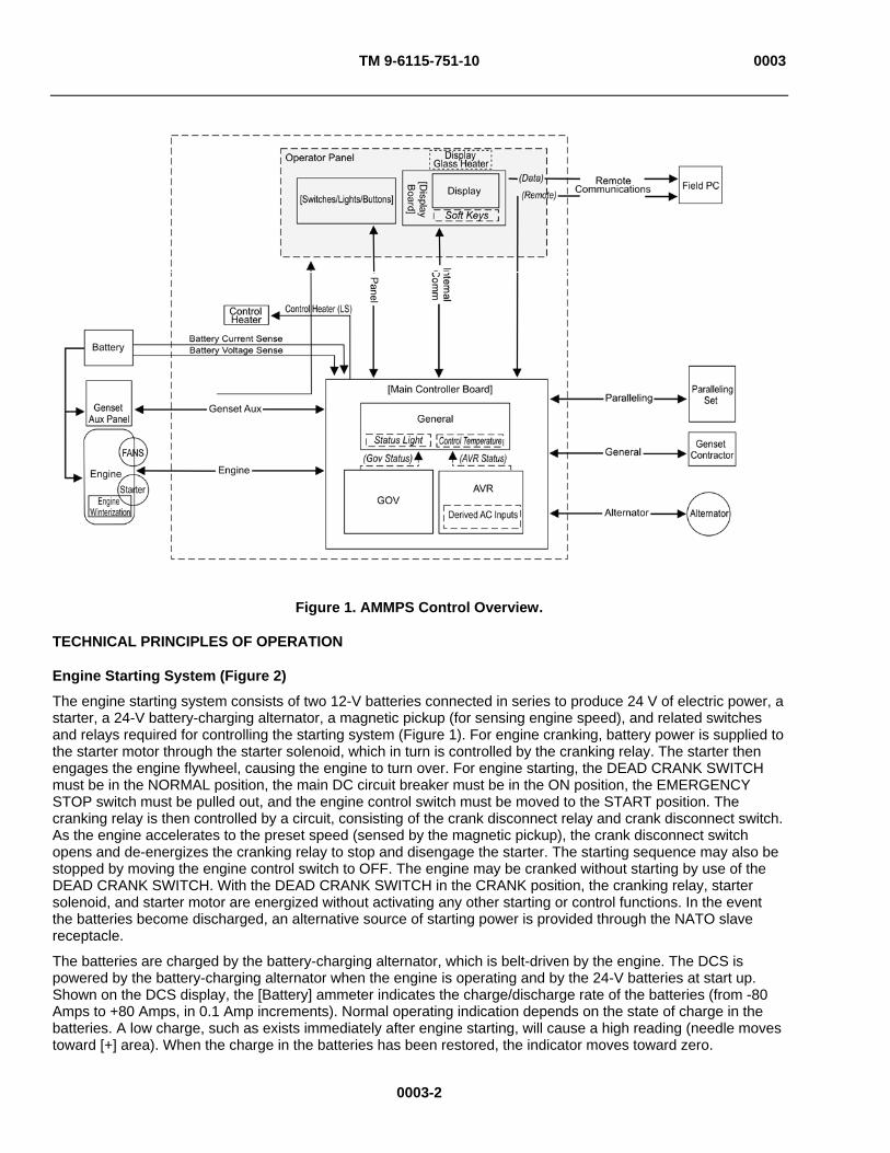
TM 9-6115-751-10 0003
Figure 1. AMMPS Control Overview.
TECHNICAL PRINCIPLES OF OPERATION
Engine Starting System (Figure 2)
The engine starting system consists of two 12-V batteries connected in series to produce 24 V of electric power, a starter, a 24-V battery-charging alternator, a magnetic pickup (for sensing engine speed), and related switches and relays required for controlling the starting system (Figure 1). For engine cranking, battery power is supplied to the starter motor through the starter solenoid, which in turn is controlled by the cranking relay. The starter then engages the engine flywheel, causing the engine to turn over. For engine starting, the DEAD CRANK SWITCH must be in the NORMAL position, the main DC circuit breaker must be in the ON position, the EMERGENCY STOP switch must be pulled out, and the engine control switch must be moved to the START position. The cranking relay is then controlled by a circuit, consisting of the crank disconnect relay and crank disconnect switch. As the engine accelerates to the preset speed (sensed by the magnetic pickup), the crank disconnect switch opens and de-energizes the cranking relay to stop and disengage the starter. The starting sequence may also be stopped by moving the engine control switch to OFF. The engine may be cranked without starting by use of the DEAD CRANK SWITCH. With the DEAD CRANK SWITCH in the CRANK position, the cranking relay, starter solenoid, and starter motor are energized without activating any other starting or control functions. In the event the batteries become discharged, an alternative source of starting power is provided through the NATO slave receptacle.
The batteries are charged by the battery-charging alternator, which is belt-driven by the engine. The DCS is powered by the battery-charging alternator when the engine is operating and by the 24-V batteries at start up. Shown on the DCS display, the [Battery] ammeter indicates the charge/discharge rate of the batteries (from -80 Amps to +80 Amps, in 0.1 Amp increments). Normal operating indication depends on the state of charge in the batteries. A low charge, such as exists immediately after engine starting, will cause a high reading (needle moves toward [+] area). When the charge in the batteries has been restored, the indicator moves toward zero.
0003-2
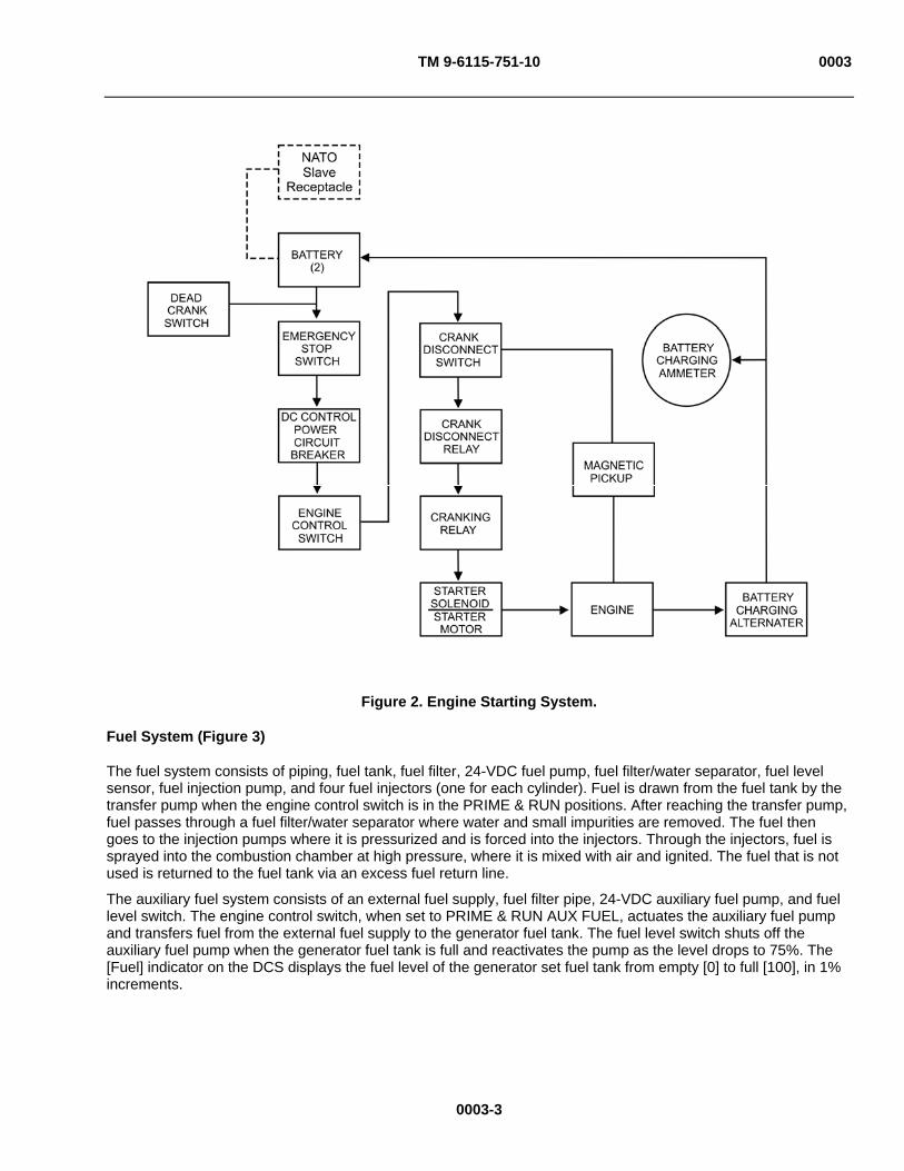
TM 9-6115-751-10 0003
Figure 2. Engine Starting System.
Fuel System (Figure 3)
The fuel system consists of piping, fuel tank, fuel filter, 24-VDC fuel pump, fuel filter/water separator, fuel level sensor, fuel injection pump, and four fuel injectors (one for each cylinder). Fuel is drawn from the fuel tank by the transfer pump when the engine control switch is in the PRIME & RUN positions. After reaching the transfer pump, fuel passes through a fuel filter/water separator where water and small impurities are removed. The fuel then goes to the injection pumps where it is pressurized and is forced into the injectors. Through the injectors, fuel is sprayed into the combustion chamber at high pressure, where it is mixed with air and ignited. The fuel that is not used is returned to the fuel tank via an excess fuel return line.
The auxiliary fuel system consists of an external fuel supply, fuel filter pipe, 24-VDC auxiliary fuel pump, and fuel level switch. The engine control switch, when set to PRIME & RUN AUX FUEL, actuates the auxiliary fuel pump and transfers fuel from the external fuel supply to the generator fuel tank. The fuel level switch shuts off the auxiliary fuel pump when the generator fuel tank is full and reactivates the pump as the level drops to 75%. The [Fuel] indicator on the DCS displays the fuel level of the generator set fuel tank from empty [0] to full [100], in 1% increments.
0003-3

TM 9-6115-751-10 0003
Figure 3. Fuel System.
Engine Cooling System (Figure 4)
The engine cooling system consists of a radiator, hoses, thermostat, water pump, electric fan, temperature sensor, and cooling jackets. The water pump forces coolant through passages (cooling jackets) in the engine block and cylinder head where the coolant absorbs heat from the engine. When the engine reaches normal operating temperature, the thermostat opens and the heated coolant flows through the upper radiator hose assembly into the radiator. Air circulates through the radiator, reducing coolant temperature.
A coolant high-temperature logic control provides automatic shutdown in the event that coolant temperature exceeds 225 plus or minus (±) 5°F (107 ± 3°C). The [Coolant] indicator on the DCS displays coolant temperature range from 100°F to 260°F (38°C to 127°C).
Cold outside temperatures make starting the engine difficult. To improve engine starting, the generator set has two starting aids: standard air intake heaters mounted in the intake manifold and an optional winterization kit. The air intake heaters warm the air in the combustion chamber to assist with ignition when the ambient air temperature is below +21°F (-6°C). The winterization kit warms the engine coolant and thus the engine block when the ambient air temperature is between -25°F and -50°F (-32°C and -45.56°C).
0003-4
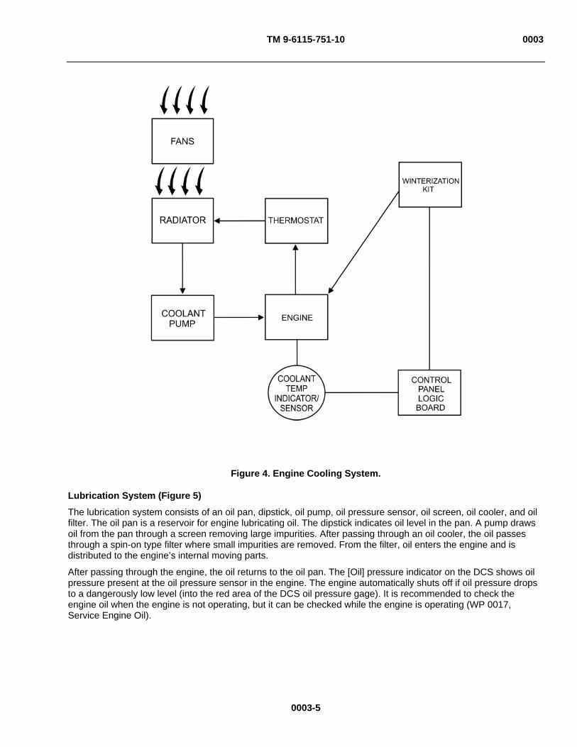
TM 9-6115-751-10 0003
Figure 4. Engine Cooling System.
Lubrication System (Figure 5)
The lubrication system consists of an oil pan, dipstick, oil pump, oil pressure sensor, oil screen, oil cooler, and oil filter. The oil pan is a reservoir for engine lubricating oil. The dipstick indicates oil level in the pan. A pump draws oil from the pan through a screen removing large impurities. After passing through an oil cooler, the oil passes through a spin-on type filter where small impurities are removed. From the filter, oil enters the engine and is distributed to the engine’s internal moving parts.
After passing through the engine, the oil returns to the oil pan. The [Oil] pressure indicator on the DCS shows oil pressure present at the oil pressure sensor in the engine. The engine automatically shuts off if oil pressure drops to a dangerously low level (into the red area of the DCS oil pressure gage). It is recommended to check the engine oil when the engine is not operating, but it can be checked while the engine is operating (WP 0017, Service Engine Oil).
0003-5
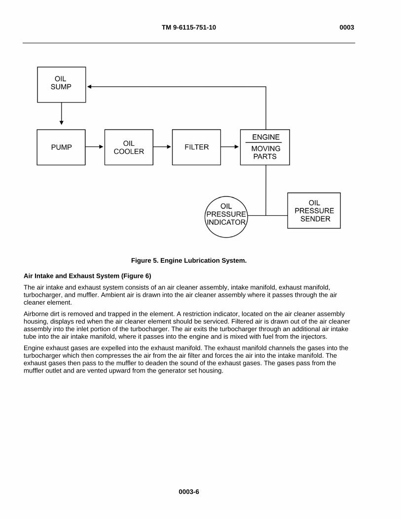
TM 9-6115-751-10 0003
Figure 5. Engine Lubrication System.
Air Intake and Exhaust System (Figure 6)
The air intake and exhaust system consists of an air cleaner assembly, intake manifold, exhaust manifold, turbocharger, and muffler. Ambient air is drawn into the air cleaner assembly where it passes through the air cleaner element.
Airborne dirt is removed and trapped in the element. A restriction indicator, located on the air cleaner assembly housing, displays red when the air cleaner element should be serviced. Filtered air is drawn out of the air cleaner assembly into the inlet portion of the turbocharger. The air exits the turbocharger through an additional air intake tube into the air intake manifold, where it passes into the engine and is mixed with fuel from the injectors.
Engine exhaust gases are expelled into the exhaust manifold. The exhaust manifold channels the gases into the turbocharger which then compresses the air from the air filter and forces the air into the intake manifold. The exhaust gases then pass to the muffler to deaden the sound of the exhaust gases. The gases pass from the muffler outlet and are vented upward from the generator set housing.
0003-6

TM 9-6115-751-10 0003
Figure 6. Air Intake and Exhaust System.
Output Supply System (Figure 7)
The output supply system consists of the AC generator, output terminal board, voltage selection board, Automatic Voltage Regulator (AVR), Ampere Meter – Voltage Meter (AM – VM), AC circuit interrupt relay, and contactor. Power created by the generator is supplied through the voltage selection board and the contactor to the output terminals on the output terminal board. For more information on the theory and practice of electrical generation, refer to FM 5-424, Theater of Operations Electrical Systems.
The voltage selection board allows configuration of the generator set for the following voltage ranges:
120/208V, 3 phase, 4 wire
240/416V, 3 phase, 4 wire
The AC CIRCUIT INTERRUPT switch controls the AC circuit interrupter relay. The relay enables or interrupts the power flow between the voltage selection board and the output terminals by opening and closing the contactor. The AC circuit interrupter relay also automatically opens the contactor during any of the faults that require a shutdown.
0003-7

TM 9-6115-751-10 0003
The AVR senses AC voltage output and provides controlled voltage to the AC generator exciter to maintain the desired AC generator output voltage. [Voltage] and [Current] are indicated on the operator control screen on the DCS. The [Genset Voltage] panel on the DCS displays the [Voltage] AC output of the unit. The [Bus Voltage] panel on the DCS displays the [Voltage] AC output at the output terminal board. The [Genset Current] screen on the DCS displays the output of the unit in amperes.
Figure 7. Output Supply System.
END OF WORK PACKAGE
0003-8
TM 9-6115-751-10
CHAPTER 2
OPERATOR INSTRUCTIONS FOR
AMMPS 15KW GENERATOR SET

TM 9-6115-751-10
CHAPTER 2
OPERATOR INSTRUCTIONS
WORK PACKAGE INDEX
Title WP Sequence No.
DESCRIPTIONS AND USE OF OPERATOR CONTROLS AND INDICATORS................................................. 0004
OPERATION UNDER USUAL CONDITIONS ..................................................................................................... 0005
PARALLEL OPERATION..................................................................................................................................... 0006
OPERATION UNDER UNUSUAL CONDITIONS ................................................................................................ 0007
EMERGENCY ...................................................................................................................................................... 0008

TM 9-6115-751-10 0004
0004-1
OPERATOR MAINTENANCE
AMMPS 15KW GENERATOR SET
DESCRIPTIONS AND USE OF OPERATOR CONTROLS AND INDICATORS
INTRODUCTION
Each table in this WP lists a key, control/indicator, and its associated function (Tables 1 — 17).
DCS
The DCS (Figure 1) is a microprocessor-based control that allows the operator and maintainer to start/stop the generator set, operate the generator contactor, switch box contactor (if present), adjust voltage and frequency, clear/reset generator faults, and perform other necessary functions to provide power. It is mounted in the upper-right corner of the generator set rear panel. A self-supporting hinged door provides access to the control panel.
The DCS manages display and control functions through two internal electronic circuit boards: one board manages the control panel and control functions for generator set output, and the second board manages the interface between the engine/AC generator and the control panel.
The control panel is mounted to the forward face of the DCS. The control panel features a combination of mechanical switches and a LCD with soft keys.

TM 9-6115-751-10 0004
Figure 1. Screen Navigation.
0004-2

TM 9-6115-751-10 0004
0004-3
Table 1. Screen Navigation.
KEY CONTROL/INDICATOR FUNCTION
Main screen Default screen. Displays after system power up and during operation to show unit configuration and operating status.
[Adjustments] screen 1 Center soft key [Adjustments] from main screen.
Used to adjust the voltage, generator set hours, time and date, temperature/pressure units of measure, winterization kit test command, and display screen(s) brightness. The function heading will be highlighted with a movable cursor upon activation of this screen.
[Adjustments] screen 2 This screen is reached by pressing [ Previous] + [Next ] simultaneously for 2 sec from [Adjustments] screen 1.
Used to [Select] and [Adjust] the [Frequency], [Adjust Governor], and [Automatic Voltage Regulator] (AVR) [Gain], [Reset] [Governor] and [AVR Gain], and display [Genset Running Time].
Parallel adjustments screen This screen is reached by pressing [Parallel Adj] soft key on [Adjustments] screen 2.
Used to monitor [Total KVAR] and [Total KW], to adjust [KW Gain], [KW Offset], [KVAR Gain] and [KVAR Offset] and to return to default settings by pushing keys to [Reset Gains] and [Reset Offsets].
[Maintenance] screen Not to be used by the operator. Should the maintenance screen be accidentally selected, press the [Exit] key to return to the main screen.
The LCD screen for the AMMPS 15 kW generator set displays five screens (Table 1) (Figure 1). Soft keys mounted under the display screen allow navigation between the display screens.
Each screen has an [Exit] soft key that will redirect the user back to the main screen at any time. Additionally, the [Adjustments] screen 1 and [Maintenance] screen automatically redirect the operator to the main screen if idle for 5 min. The [Adjustments] screen 2 and [Parallel Adj.] screen redirects the operator to the main screen when idle for 2 min.
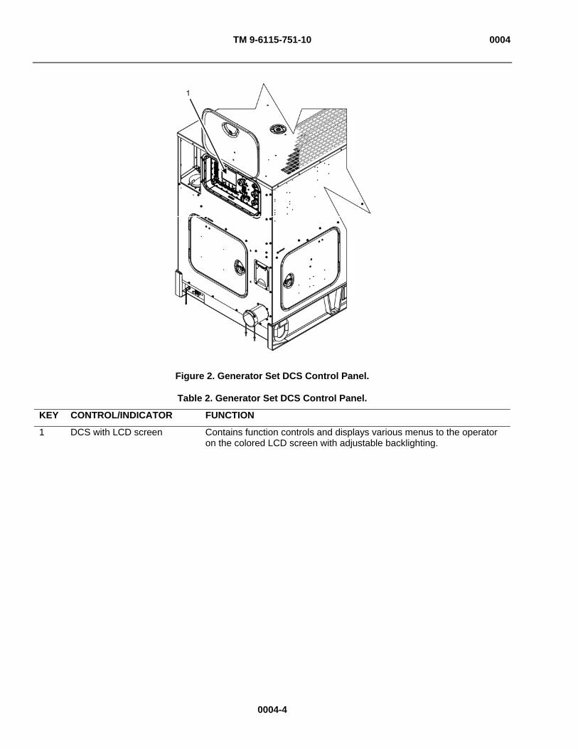
TM 9-6115-751-10 0004
Figure 2. Generator Set DCS Control Panel.
Table 2. Generator Set DCS Control Panel.
KEY CONTROL/INDICATOR FUNCTION
1 DCS with LCD screen Contains function controls and displays various menus to the operator on the colored LCD screen with adjustable backlighting.
0004-4

TM 9-6115-751-10 0004
Figure 3. DCS Control Panel.
Table 3. DCS Control Panel.
KEY CONTROL/INDICATOR FUNCTION
1 PANEL LIGHTS Push switch. Turns on and off the built-in panel lighting.
2 LCD screen Displays various menus, diagnostics, and functional information to the operator. There is a 4-sec delay at start up. The delay increases as ambient temperature decreases.
3 EMERGENCY STOP Push-pull switch. Rapidly shuts down the unit. This control is used for emergencies and safety lockout only.
4 FAULT RESET Push switch. Clears fault and warning messages after they have been corrected.
5 Engine control switch Rotary switch. Controls start and stop of engine and fuel source logic. When first turned on, activates the control panel and main controller boards (Figure 5).
6 Soft keys Touch-control switches. Used to control the display, navigate from screen to screen, and make adjustments (Figure 7).
7 BATTLESHORT Toggle switch. Overrides faults and warnings when ON that would normally result in an automatic shutdown (WP 0007, Operation Under Unusual Conditions). Remains OFF during normal operation.
0004-5

TM 9-6115-751-10 0004
Table 3. Main Display Screen — Continued.
KEY CONTROL FUNCTION
8 UNIT
PARALLEL
[PARALLEL]
[UNIT]
Push switch. Places AC generator in unit or parallel mode. Parallel logic splits the load between two or more generator sets.
Enables DCS load share logic, allowing parallel operation.
Disables load share logic.
9 AC CIRCUIT INTERRUPT Push switch. Controls the operation of the generator contactor, which allows the generator set to be connected or disconnected to the load.
Figure 4. DEAD CRANK SWITCH.
Table 4. DEAD CRANK SWITCH.
KEY CONTROL FUNCTION
1 CRANK Three-position toggle switch. Disables power to the fuel pump, allowing engine to crank but not start.
2 NORMAL Three-position toggle switch. Enables power to fuel pump and starter.
3 OFF Three-position toggle switch. Interrupts all power to starter.
0004-6
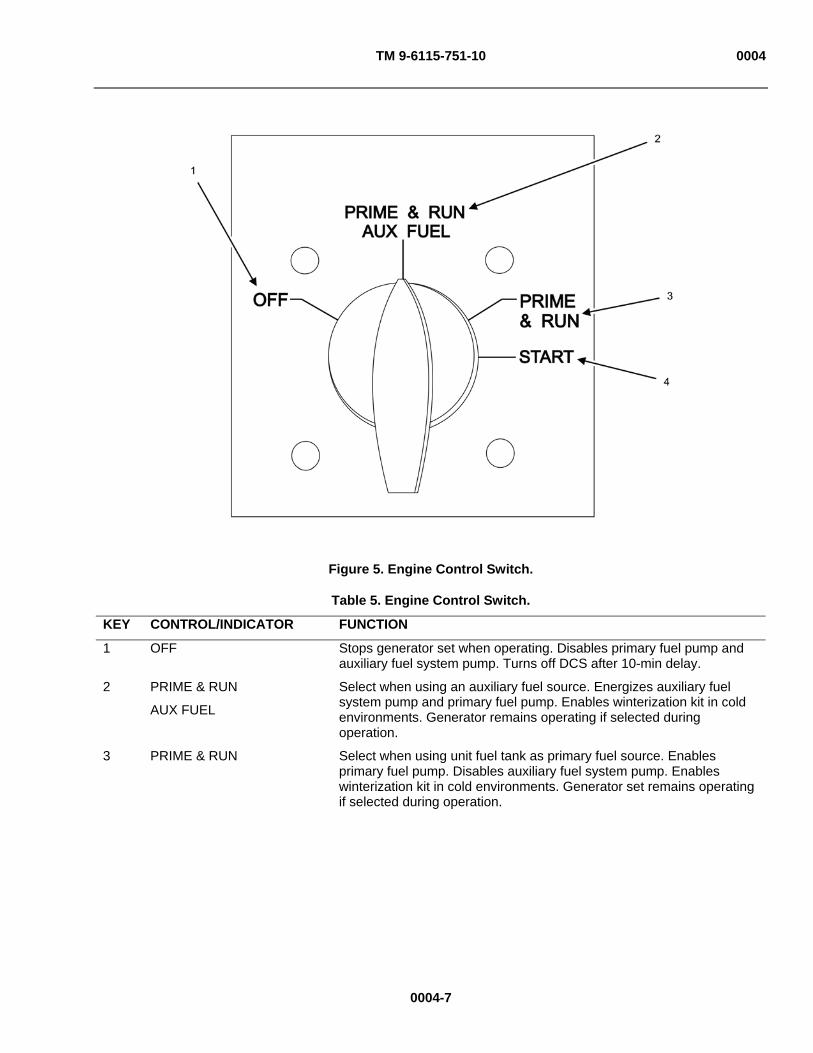
TM 9-6115-751-10 0004
Figure 5. Engine Control Switch.
Table 5. Engine Control Switch.
KEY CONTROL/INDICATOR FUNCTION
1 OFF Stops generator set when operating. Disables primary fuel pump and auxiliary fuel system pump. Turns off DCS after 10-min delay.
2 PRIME & RUN
AUX FUEL
Select when using an auxiliary fuel source. Energizes auxiliary fuel system pump and primary fuel pump. Enables winterization kit in cold environments. Generator remains operating if selected during operation.
3 PRIME & RUN Select when using unit fuel tank as primary fuel source. Enables primary fuel pump. Disables auxiliary fuel system pump. Enables winterization kit in cold environments. Generator set remains operating if selected during operation.
0004-7
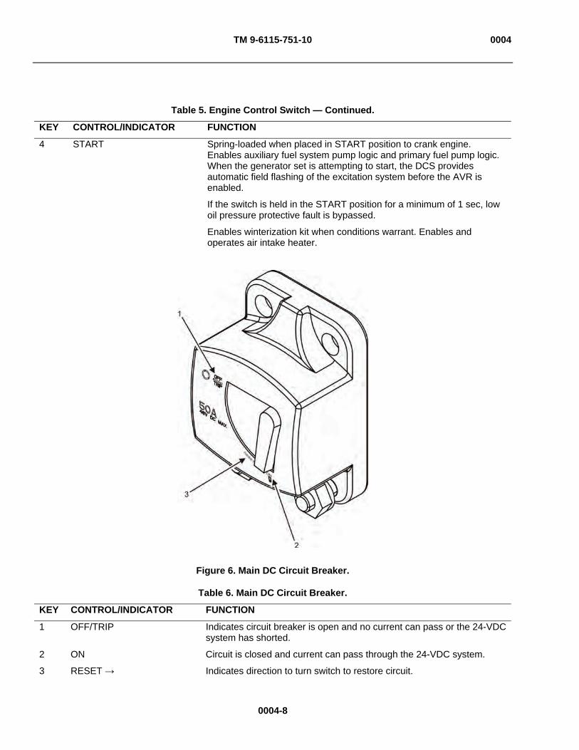
TM 9-6115-751-10 0004
Table 5. Engine Control Switch — Continued.
KEY CONTROL/INDICATOR FUNCTION
4 START Spring-loaded when placed in START position to crank engine. Enables auxiliary fuel system pump logic and primary fuel pump logic. When the generator set is attempting to start, the DCS provides automatic field flashing of the excitation system before the AVR is enabled.
If the switch is held in the START position for a minimum of 1 sec, low oil pressure protective fault is bypassed.
Enables winterization kit when conditions warrant. Enables and operates air intake heater.
Figure 6. Main DC Circuit Breaker.
Table 6. Main DC Circuit Breaker.
KEY CONTROL/INDICATOR FUNCTION
1 OFF/TRIP Indicates circuit breaker is open and no current can pass or the 24-VDC system has shorted.
2 ON Circuit is closed and current can pass through the 24-VDC system.
3 RESET Indicates direction to turn switch to restore circuit.
0004-8

TM 9-6115-751-10 0004
Figure 7. Voltage Selection Board.
Table 7. Voltage Selection Board.
KEY CONTROL/INDICATOR FUNCTION
1 120/208-V 3 Phase Generator set configured for 120/208-V three-phase load.
2 240/416-V 3 Phase Generator set configured for 240/416-V three-phase load.
0004-9

MT 4000 01-157-5116-9
Figure 8. Main Display Screen (Showing 3-Phase Configuration).
Table 8. Main Display Screen.
KEY CONTROL/INDICATOR FUNCTION
1 [Fault XXX:] Displays when fault condition exists. Fault codes and descriptions are found in WP 0011, DCS Fault & Warning Codes and Descriptions.
2 [Power] [kW] Indicates total load of the unit in kilowatts.
3 [Freq] [Hz] Indicates the output frequency in hertz.
4 [Genset Mode:] Displays the operational readiness and status of the unit:
[Ready] Engine ready to start.
[Not Ready to Crank] Engine not ready to start.
[Rated Voltage and Frequency] Unit operating at specified output.
[Powering Down] Unit stopped. After unit is shut down, DCS will remain illuminated for 10 min.
[Delay to Crank—Wtr Kit xx min] Winterization kit activated; xx min until engine is ready to start.
[Delay to Crank—Glw Plg xx sec] Glow plugs (Glw Plg) activated; xx sec until engine is ready to start.
[Start-up Status: Ready] Engine is ready to start.
0004-10

TM 9-6115-751-10 0004
0004-11
Table 8. Main Display Screen — Continued.
KEY CONTROL/INDICATOR FUNCTION
4 [Not Available] Winterization kit nonresponsive or not installed.
[Running] Engine successfully started and operational.
[Unknown] Communication not established between display control board and main control board interface.
5 [Fuel]
Green
Yellow
Red
Indicates fuel level as percentage of total available fuel:
Fuel level satisfactory.
Fuel level low, in warning area.
Fuel level very low; fault indicated.
6 [Configuration:]
[—kW]
[—Phase]
Displays capacity in kW, generator [Phase], Voltage (V), and [Hz]) settings:
Load (in kW)
Phase:
[3 Phase]—Three Phase
[—V] Voltage:
[120 V], [120/240 V], or [120/208 V]
[—Hz] Frequency:
[50], [60], or [400] Hz
7 [Battery] [Vdc]
Green
Yellow
Red
Indicates battery voltage in [Vdc].
Voltage level satisfactory.
Voltage level low, in warning area.
Voltage level very low, fault indicated.
8 [Battery] [Adc]
Green
Yellow
Red
Indicates charge level of the batteries in [Adc]:
Amperage satisfactory.
Amperage low, in warning area.
Amperage very low; fault indicated.
9 [Oil] [PSI]/[kPa]
Green
Yellow
Red
Indicates engine oil pressure during operation. Can display metric or standard units of measure:
Oil pressure satisfactory.
Oil pressure low, in warning area.
Oil pressure very low; fault indicated.
10 [Hours] Displays total operating time of the generator set.
11 Date, Time Displays current date (YYYY-MM-DD) and time (HH:MM:SS).

TM 9-6115-751-10 0004
0004-12
Table 8. Main Display Screen — Continued.
KEY CONTROL/INDICATOR FUNCTION
12 [Coolant] [F]/[C]
Green
Yellow
Red
Indicates engine coolant temperature when operating. Can display metric or standard units of measure:
Coolant temperature satisfactory.
Coolant temperature low, in warning area.
Coolant temperature very low; fault indicated.
13 [Genset Current] [Aac] Indicates generator set output in amperes by line.
14 [Maintenance] Soft key designator. See Key 17 for all possible display options.
15 [Bus Voltage L-L] [Vac]
[Bus Voltage L-N] [Vac]
Indicates voltage generated at the output terminal board from Line-to-Line (L-L).
Indicates voltage generated at the output terminal board from Line-to-Neutral (L-N).
16 [Genset Voltage L-L] [Vac]
[Genset Voltage L-N] [Vac]
Displays the L-L voltage for each phase simultaneously from the generator set to the generator [Contactor] output bus.
Displays the L-N voltage for each phase simultaneously from the generator set to the generator [Contactor] output bus.
17 Soft Key Function(s) Five soft keys display screen-specific functions. Control panel display screen indicates the current soft key function above each push-button switch. Each soft key has a dedicated label and function relative to each screen. When the function for a soft key is not available or invalid, all of the foreground attributes of the soft key label will be 50% gray in color.
[About] Displays the software versions that are installed for both the main controller and the display controller.
[L-N] or [L-L] Toggles the voltage displays L-N or L-L. Function is suppressed in single phase.
[Unload] Unloads generator set during parallel operation. Function is suppressed when in [UNIT] mode or without load.
[Adjustments] Changes the display context to the first adjustments screen (Figure 9).
[Aux Disable] or [Aux Enable] Disables or enables auxiliary fuel pump control. Function not available when engine control switch is not in PRIME & RUN AUX FUEL position.
[Maintenance] Changes the display context to the first maintenance screen.
[Select] Selects highlighted parameter for adjustment.
[ Previous] Moves the highlighted parameter one item to the left (if the leftmost parameter is highlighted, wraps to the rightmost).
[Next ] Moves the highlighted parameter one item to the right (if the rightmost parameter is highlighted, wraps to the leftmost).
[Exit] Returns to the main screen.

TM 9-6115-751-10 0004
0004-13
Table 8. Main Display Screen — Continued.
KEY CONTROL/INDICATOR FUNCTION
[Cancel] Cancels adjustment(s) made and restores previously-selected value. Cursor remains at the selected parameter.
[Accept] Accepts new parameter value.
[ + ] Moves new parameter value to the next higher step.
[ - ] Moves new parameter value to the next lower step.
[ Previous]+[Next ] When pressed simultaneously for 2 sec moves to [Adjustment] screen 2 from [Adjustment] screen 1.
18 [Battleshort]
[Active]
[Inactive]
Indicates position of the Battleshort switch.
Battleshort operational. Unit will only stop on EMERGENCY STOP, short circuit, or overspeed fault.
Battleshort not operational. All fault functions enabled.
19 [Mode]
[Unit]
[Parallel]
Indicates generator set configuration (unit or parallel).
Operating as a PU.
Operating as a PP with one or more other generators.
20 [Switchbox]
[Open]
[Closed]
Displays status of connection between units when operating in parallel:
Not connected.
Connected.
21 [Contactor]
[OPEN]
[CLOSED]
Indicates position of contactor.
Power not supplied to load.
Power supplied to load.
22 [Warning XXX:] This line displays only when the unit is in a pre-failure condition or has a defect (WP 0011, DCS Fault & Warning Codes and Descriptions).
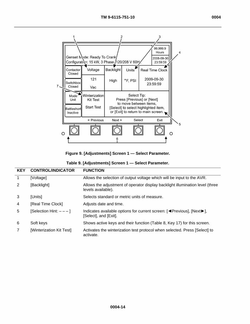
TM 9-6115-751-10 0004
Figure 9. [Adjustments] Screen 1 — Select Parameter.
Table 9. [Adjustments] Screen 1 — Select Parameter.
KEY CONTROL/INDICATOR FUNCTION
1 [Voltage] Allows the selection of output voltage which will be input to the AVR.
2 [Backlight] Allows the adjustment of operator display backlight illumination level (three levels available).
3 [Units] Selects standard or metric units of measure.
4 [Real Time Clock] Adjusts date and time.
5 [Selection Hint: – – – ] Indicates available options for current screen: [ Previous], [Next ], [Select], and [Exit].
6 Soft keys Shows active keys and their function (Table 8, Key 17) for this screen.
7 [Winterization Kit Test] Activates the winterization test protocol when selected. Press [Select] to activate.
0004-14

TM 9-6115-751-10 0004
Figure 10. [Adjustments] Screen 1 — Adjust.
0004-15

TM 9-6115-751-10 0004
0004-16
Table 10. [Adjustments] Screen 1 — Adjust.
KEY CONTROL/INDICATOR FUNCTION
1 [Voltage] Adjusts voltage output. Press [Select] to activate.
2 [XXX Vac] Displays the voltage value selected for output. Adjust with [ + ] and [ - ] keys in 1 VAC increments. Press [Accept] to confirm. Press [Cancel] to reset adjustment.
3 [Backlight] Adjusts backlight illumination. Three levels are available. Press [Select] to activate.
4 [High]
[Medium]
[Low]
Displays the level of illumination. Adjust with [ + ] and [ - ] keys. Moves one increment per adjustment. Press [Accept] to confirm. Press [Cancel] to reset adjustment.
5 [Units] Selects standard or metric units of measure for coolant temperature and oil pressure. Highlight desired parameter and then press [Select] to activate.
6 [Real Time Clock] Highlight with the cursor to adjust the time (HH:MM:SS) and date (YYYY-MM-DD). Press [Select] to activate.
7 [°F, PSI] or [°C, kPa] Selects standard or metric units of measure for display. Adjust with [ + ] and [ - ] keys. Press [Accept] to confirm. Press [Cancel] to reset adjustment.
8 [Real Time Clock] Segments Displays current time (HH:MM:SS) and date (YYYY-MM-DD). Adjust with [ + ] and [ - ] keys. Moves one significant increment per adjustment. Press [Accept] to confirm. Press [Cancel] to reset adjustment.
9 [Select Tip: XXXXX] Verbiage showing available options for current screen such as: [ Previous], [Next ], [Accept], [Cancel], and [Exit] keys and a description of their functions. Varies with screen being displayed.
10 Soft keys Shows active keys and their function (Table 8, Key 17) for this screen.
11 [Winterization Kit Test] Activates the winterization test protocol when selected. Press [Accept] to activate.

TM 9-6115-751-10 0004
Figure 11. [Adjustments] Screen 2 — Select Parameter.
Table 11. [Adjustments] Screen 2 — Select Parameter.
KEY CONTROL/INDICATOR FUNCTION
1 [Frequency Select] Highlight with cursor to select 50 Hz or 60 Hz frequency on Mode I units. This function is suppressed in Mode 2, 400 Hz units. Press [Select] soft key to activate.
2 [Frequency Adjust] Highlight with cursor to adjust frequency of electrical output in 1 Hz increments. Press [Select] soft key to activate.
3 [Governor Gain] Highlight with cursor to adjust engine speed governor setting (the allowable percentage of engine speed under/over revolutions per minute (rpm) setting). Press [Select] soft key to activate.
4 [AVR Gain] Adjusts AVR gain (the allowable percentage of generator voltage under/over setting).
5 [Gov/AVR Gain Reset]
Allows the reset of governor and AVR gain settings to the default settings.
0004-17
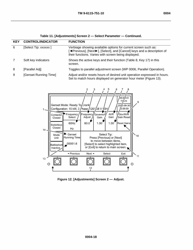
TM 9-6115-751-10 0004
Table 11. [Adjustments] Screen 2 — Select Parameter — Continued.
KEY CONTROL/INDICATOR FUNCTION
6 [Select Tip: xxxxxx ] Verbiage showing available options for current screen such as: [ Previous], [Next ], [Select], and [Cancel] keys and a description of their functions. Varies with screen being displayed.
7 Soft key indicators Shows the active keys and their function (Table 8, Key 17) in this screen.
8 [Parallel Adj] Toggles to parallel adjustment screen (WP 0006, Parallel Operation).
9 [Genset Running Time] Adjust and/or resets hours of desired unit operation expressed in hours. Set to match hours displayed on generator hour meter (Figure 13).
Figure 12. [Adjustments] Screen 2 — Adjust.
0004-18
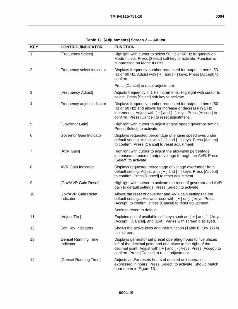
TM 9-6115-751-10 0004
0004-19
Table 12. [Adjustments] Screen 2 — Adjust.
KEY CONTROL/INDICATOR FUNCTION
1 [Frequency Select] Highlight with cursor to select 50 Hz or 60 Hz frequency on Mode I units. Press [Select] soft key to activate. Function is suppressed on Mode II units.
2 Frequency select indicator Displays frequency number requested for output in hertz: 50 Hz or 60 Hz. Adjust with [ + ] and [ - ] keys. Press [Accept] to confirm.
Press [Cancel] to reset adjustment.
3 [Frequency Adjust] Adjusts frequency in 1 Hz increments. Highlight with cursor to select. Press [Select] soft key to activate.
4 Frequency adjust indicator Displays frequency number requested for output in hertz (50 Hz or 60 Hz) and allows for increase or decrease in 1 Hz increments. Adjust with [ + ] and [ - ] keys. Press [Accept] to confirm. Press [Cancel] to reset adjustment.
5 [Governor Gain] Highlight with cursor to adjust engine speed governor setting. Press [Select] to activate.
6 Governor Gain Indicator Displays requested percentage of engine speed over/under default setting. Adjust with [ + ] and [ - ] keys. Press [Accept] to confirm. Press [Cancel] to reset adjustment.
7 [AVR Gain] Highlight with cursor to adjust the allowable percentage increase/decrease of output voltage through the AVR. Press [Select] to activate.
8 AVR Gain Indicator Displays requested percentage of voltage over/under from default setting. Adjust with [ + ] and [ - ] keys. Press [Accept] to confirm. Press [Cancel] to reset adjustment.
9 [Gov/AVR Gain Reset] Highlight with cursor to activate the reset of governor and AVR gain to default settings. Press [Select] to activate.
10 Gov/AVR Gain Reset Indicator
Allows the reset of governor and AVR gain settings to the default settings. Activate reset with [ + ] or [ - ] keys. Press [Accept] to confirm. Press [Cancel] to reset adjustment.
Settings revert to default.
11 [Adjust Tip ] Explains use of available soft keys such as: [ + ] and [ - ] keys, [Accept], [Cancel], and [Exit]. Varies with screen displayed.
12 Soft Key Indicators Shows the active keys and their function (Table 8, Key 17) in this screen.
13 Genset Running Time Indicator
Displays generator set preset operating hours to five places left of the decimal point and one place to the right of the decimal point. Adjust with [ + ] and [ - ] keys. Press [Accept] to confirm. Press [Cancel] to reset adjustment.
14 [Genset Running Time] Adjusts and/or resets hours of desired unit operation expressed in hours. Press [Select] to activate. Should match hour meter in Figure 13.

TM 9-6115-751-10 0004
Figure 13. [Parallel Adj] Screen.
Table 13. [Parallel Adj] Screen.
KEY CONTROL/INDICATOR FUNCTION
1 [KW Gain] Adjusts the kilowatt gain values in the DCS AVR control logic.
2 [KW Offset] Adjusts the kilowatt offset values in the DCS AVR control logic.
3 [KVAR Gain] Adjusts the kilovolt-ampere reactive gain values in the DCS AVR control logic.
4 [KVAR Offset] Adjusts the kilovolt-ampere reactive offset values in the DCS AVR control logic.
5 [Reset Gains] Returns gain value to initial setting in the DCS AVR control logic.
6 [Reset Offset] Returns offset value to initial setting in the DCS AVR control logic.
7 [Select Tip: xxxxxx] Verbiage showing available options for current screen such as: [Previous], [Next], [Select], and [Cancel] keys and a description of their functions. Varies with screen being displayed.
8 [Genset Adj] Toggles display to [Adjustments] screen 2.
9 [Total KVAR] Displays kilovolt-ampere reactive variance in load sharing between generator sets as a positive or negative number. The value is used for adjustment purposes.
10 [Total KW] Displays kilowatt variance in load sharing between generator sets as a positive or negative number. The value is used for adjustment purposes.
0004-20
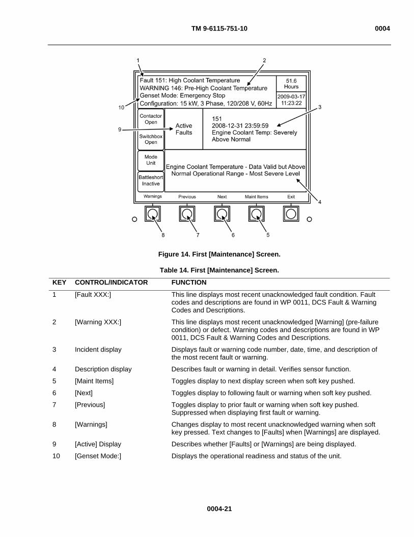
TM 9-6115-751-10 0004
Figure 14. First [Maintenance] Screen.
Table 14. First [Maintenance] Screen.
KEY CONTROL/INDICATOR FUNCTION
1 [Fault XXX:] This line displays most recent unacknowledged fault condition. Fault codes and descriptions are found in WP 0011, DCS Fault & Warning Codes and Descriptions.
2 [Warning XXX:] This line displays most recent unacknowledged [Warning] (pre-failure condition) or defect. Warning codes and descriptions are found in WP 0011, DCS Fault & Warning Codes and Descriptions.
3 Incident display Displays fault or warning code number, date, time, and description of the most recent fault or warning.
4 Description display Describes fault or warning in detail. Verifies sensor function.
5 [Maint Items] Toggles display to next display screen when soft key pushed.
6 [Next] Toggles display to following fault or warning when soft key pushed.
7 [Previous] Toggles display to prior fault or warning when soft key pushed. Suppressed when displaying first fault or warning.
8 [Warnings] Changes display to most recent unacknowledged warning when soft key pressed. Text changes to [Faults] when [Warnings] are displayed.
9 [Active] Display Describes whether [Faults] or [Warnings] are being displayed.
10 [Genset Mode:] Displays the operational readiness and status of the unit.
0004-21

TM 9-6115-751-10 0004
Figure 15. [Maintenance Items] Screen.
Table 15. [Maintenance Items] Screen.
KEY CONTROL/INDICATOR FUNCTION
1 Status Display Shows display parameter of this screen.
2 [Maintenance Items] Display Shows maintenance item in need of action by date and time the item(s) passed into active status (hour interval for scheduled maintenance achieved or passed) or next item due in numerical sequence if the item is not active.
3 [Tip] Display Shows actions required to resolve maintenance items.
4 [Maint Actions] Toggles display to next display screen when soft key pushed.
5 [Next} Toggles display to following item when soft key pushed.
6 [Previous] Toggles display to prior item when soft key pushed. Suppressed when displaying first [Maintenance Item].
7 [Faults] Toggles to display prior [Fault] screen when soft key pushed.
0004-22

TM 9-6115-751-10 0004
Figure 16. [Maintenance Actions] Screen.
Table 16. [Maintenance Actions] Screen.
KEY CONTROL/INDICATOR FUNCTION
1 [Tip] Display Shows actions required to resolve maintenance items. Actions taken are stored in the maintenance log. Items dismissed or deferred will recur as [Active Maintenance Items].
2 [Cancel] Returns display to previous screen without saving any actions selected.
3 [Completed] Saves the date and time of the maintenance action was performed in the maintenance log.
4 [Defer] Reschedules the maintenance item until a later date.
5 [Dismiss] Permanently deletes the maintenance action. Do not select this option.
0004-23
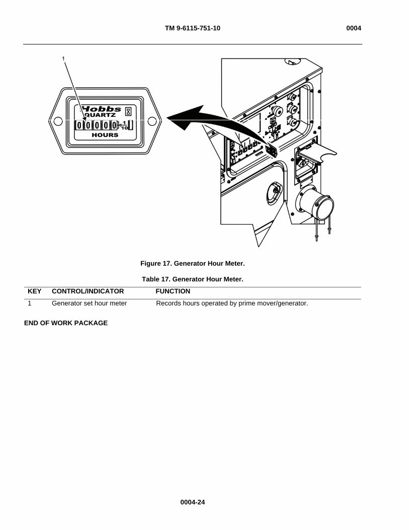
TM 9-6115-751-10 0004
Figure 17. Generator Hour Meter.
Table 17. Generator Hour Meter.
KEY CONTROL/INDICATOR FUNCTION
1 Generator set hour meter Records hours operated by prime mover/generator.
END OF WORK PACKAGE
0004-24
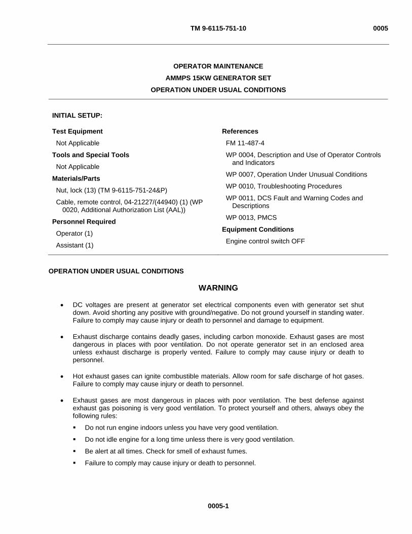
TM 9-6115-751-10 0005
0005-1
OPERATOR MAINTENANCE
AMMPS 15KW GENERATOR SET
OPERATION UNDER USUAL CONDITIONS
INITIAL SETUP:
Test Equipment
Not Applicable
Tools and Special Tools
Not Applicable
Materials/Parts
Nut, lock (13) (TM 9-6115-751-24&P)
Cable, remote control, 04-21227/(44940) (1) (WP 0020, Additional Authorization List (AAL))
Personnel Required
Operator (1)
Assistant (1)
References
FM 11-487-4
WP 0004, Description and Use of Operator Controls and Indicators
WP 0007, Operation Under Unusual Conditions
WP 0010, Troubleshooting Procedures
WP 0011, DCS Fault and Warning Codes and Descriptions
WP 0013, PMCS
Equipment Conditions
Engine control switch OFF
OPERATION UNDER USUAL CONDITIONS
WARNING
DC voltages are present at generator set electrical components even with generator set shut down. Avoid shorting any positive with ground/negative. Do not ground yourself in standing water. Failure to comply may cause injury or death to personnel and damage to equipment.
Exhaust discharge contains deadly gases, including carbon monoxide. Exhaust gases are most dangerous in places with poor ventilation. Do not operate generator set in an enclosed area unless exhaust discharge is properly vented. Failure to comply may cause injury or death to personnel.
Hot exhaust gases can ignite combustible materials. Allow room for safe discharge of hot gases. Failure to comply may cause injury or death to personnel.
Exhaust gases are most dangerous in places with poor ventilation. The best defense against exhaust gas poisoning is very good ventilation. To protect yourself and others, always obey the following rules:
Do not run engine indoors unless you have very good ventilation.
Do not idle engine for a long time unless there is very good ventilation.
Be alert at all times. Check for smell of exhaust fumes.
Failure to comply may cause injury or death to personnel.

TM 9-6115-751-10 0005
0005-2
WARNING
Exhaust gas poisoning causes dizziness, headache, loss of muscle control, sleepiness, coma, and death. If anyone shows signs of exhaust gas poisoning, get all personnel clear of AMMPS. Make sure they have lots of fresh air. Keep them warm, calm, and inactive. Get medical help. If anyone stops breathing, give artificial respiration. Failure to comply may cause injury or death to personnel.
When operating, generator set engine has hot metal surfaces that will burn flesh on contact. Shut down generator set and allow engine to cool before checks, services, and maintenance. Wear gloves and additional protective clothing as required. Failure to comply may cause injury or death to personnel.
Metal jewelry can conduct electricity and become entangled in generator set components. Remove all jewelry and do not wear loose clothing when working on equipment. Failure to comply may cause injury or death to personnel.
SITING REQUIREMENTS
1. Select the site that provides the following features:
a. Ample space for maneuvering vehicles used to move generator set(s) or trailer-mounted generator set(s).
(1) The 15 kW AMMPS dimensions are 65.0 x 36.0 in (165.1 x 91.4 cm).
(2) Allow for the dimensions and turning radius of the towing vehicle.
b. Firm, reasonably level (less than 15 degree slope on all axes), well-drained terrain that is not adjacent to low areas where exhaust fumes might collect.
c. Space on all sides for service and maintenance.
d. Generator set(s) positioned as far away as possible from occupied mobile shelters, vehicle cabs, and building ventilation system air intakes and/or other openings or duct the exhaust to a safe location.
e. Adequate ventilation to prevent recirculation of hot air exhausted from generator set
f. Adequate open-air ventilation and exhaust exposure controls when the AMMPS is positioned in protected fighting positions or revetments (barriers/walls/embankments).
g. Adequate open-air ventilation and proper placement of exhaust when AMMPS is mounted on a flatbed truck chassis or used on a system in occupied shelters.
2. Make use of natural protective barriers.
3. Modify location as required.
a. Level an area larger than the footprint of the unit if a sufficiently level area is unavailable naturally.
(1) The 15 kW AMMPS 50/60 Hz dimensions are 65.0 x 36.0 in (165.1 x 91.4 cm).
(2) The 15 kW AMMPS 400 Hz dimensions are 65.0 x 36.0 in (165.1 x 91.4 cm).
b. Remove combustible materials within 36 in (91.44 cm) of all sides of generator set.
4. Ensure the following conditions are met if using an enclosure.
a. Meet minimum enclosure requirements of 36 in (91.44 cm) from all sides.
b. Install proper exhaust pipe extensions, ducts and vents to outside or use dilution ventilation or local exhaust ventilation when the AMMPS is operated in an enclosure or building.to exhaust gas.
c. Make air inlet and outlet openings in enclosure same size as or larger than those on the generator set.
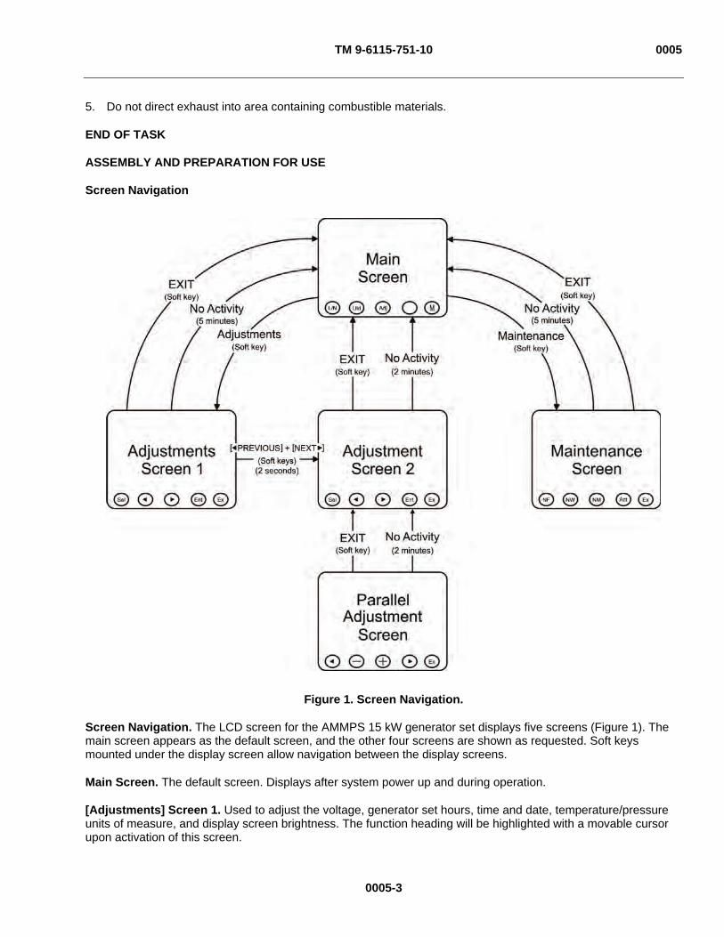
TM 9-6115-751-10 0005
5. Do not direct exhaust into area containing combustible materials.
END OF TASK
ASSEMBLY AND PREPARATION FOR USE
Screen Navigation
Figure 1. Screen Navigation.
Screen Navigation. The LCD screen for the AMMPS 15 kW generator set displays five screens (Figure 1). The main screen appears as the default screen, and the other four screens are shown as requested. Soft keys mounted under the display screen allow navigation between the display screens.
Main Screen. The default screen. Displays after system power up and during operation.
[Adjustments] Screen 1. Used to adjust the voltage, generator set hours, time and date, temperature/pressure units of measure, and display screen brightness. The function heading will be highlighted with a movable cursor upon activation of this screen.
0005-3

TM 9-6115-751-10 0005
[Adjustments] Screen 2. Used to adjust the [Frequency], [Governor Gain], Automatic Voltage Regulator [AVR Gain], [Gov/AVR Gain Reset], and [Genset Running Time]. This screen is reached by pressing [ Previous] and [Next ] simultaneously for 2 sec.
Parallel [Adjustments] Screen. Used to monitor [Total KVAR] and [Total KW], to adjust [KW Gain], [KW Offset], [KVAR Gain], and [KVAR Offset] and to return default settings by pushing keys to [Reset Gains] and [Reset Offsets]. This screen is reached by pressing [Parallel Adj] soft key on [Adjustments] 2 screen.
[Maintenance] Screen. Not to be utilized by the operator except for information gathering. If the [Maintenance] screen is accidentally selected, press the [Exit] key to return to the main screen.
Each screen has an [Exit] soft key that redirects the user back to the main screen at any time. Additionally, the [Adjustments] screen 1 and [Maintenance] screen automatically redirect the operator to the main screen if idle for 5 min. The [Adjustments] screen 2 redirects the operator to the main screen when idle for 2 min.
END OF TASK
Installation of Ground Rod
Figure 2. Grounding Connections.
1. Open output box door (Figure 6, Item 5).
2. Thread ground cable (Figure 2, Item 7) into output box through flexible sleeve (Figure 2, Item 6).
3. Lift protective cover (Figure 6, Item 2) from output terminal board (Figure 6, Item 4).
0005-4

TM 9-6115-751-10 0005
0005-5
WARNING
Do not remove the bonding jumper between GND and N unless the weapon system requires an underground system. Refer to applicable weapon system TM for specific guidance on power and connection requirements. Failure to comply may cause injury or death to personnel.
4. Ensure the bonding jumper (neutral busbar) (Figure 2, Item 5) is securely fastened between N and ground.
5. Loosen terminal (Figure 2, Item 4) nut using provided terminal nut wrench (Figure 6, Item 6) located inside output box door (Figure 6, Item 5).
6. Insert ground cable (Figure 7, Item 2) through slot (Figure 7, Item 3) on terminal marked GND.
7. Tighten terminal nut (Figure 7, Item 1) using terminal nut wrench (Figure 6, Item 6).
NOTE
Three sections of ground rod and three couplings are provided with the AMMPS 15 kW generator set in a rack inside the left door. Desired ground rod depth is 8 ft (2.44 m) or more. Make every attempt possible to obtain this depth or coverage of the ground rods.
Two tools can be used to drive the ground rod into the ground: a slide hammer assembly (Figure 3) and a sledge hammer (Figure 4). The slide hammer assembly provides the safest and easiest method of driving the ground rod and should be used unless it is unavailable. Use of the slide hammer is described in steps 8 and 9. Use of the sledge hammer is described in step 10.
8. Install ground rod (Figure 2, Item 1) using slide hammer (Figure 3, Item 7) assembly.
a. Install impact disk (Figure 3, Item 3) on slide hammer rod (Figure 3, Item 1).
b. Tighten impact disk (Figure 3, Item 3) to end of threads on slide hammer rod (Figure 3, Item 1).
c. Install lock washer and nut (Figure3, Item 4).
d. Tighten lock washer and nut (Figure 3, Item 4) securely against impact disk (Figure 3, Item 3).
e. Remove nut (Figure 3, Item 2), if installed.
NOTE
Ground rod (Figure 2, Item 1) must be installed within 5 feet (ft) (1.52 meter (m)) of flexible sleeve (Figure 2, Item 6). Ground cable (Figure 2, Item 7) is 6 ft (1.83 m) in length.
For additional grounding information, consult FM 11-487-4, Installation Practices: Grounding, Bonding, and Shielding.
f. Position slide hammer (Figure 3, Item 7) on slide hammer rod (Figure 3, Item 1).
g. Install nut (Figure 3, Item 2), and tighten to end of threads on slide hammer rod (Figure 3, Item 1).
h. Install ground rod coupling (Figure 3, Item 6) to ground rod (Figure 3, Item 5) and screw slide hammer into coupling (Figure 3, Item 6).
i. Ensure slide hammer rod (Figure 3, Item 1) seats on ground rod (Figure 3, Item 5).
j. Drive ground rod (Figure 3, Item 5) into ground until coupling (Figure 3, Item 6) is just above surface.
k. Remove slide hammer (Figure 3, Item 7) and install another section of ground rod (Figure 3, Item 5).
l. Install another coupling (Figure 3, Item 6) to ground rod (Figure 3, Item 5) and screw slide hammer rod (Figure 3, Item 1) into coupling (Figure 3, Item 6).
m. Drive ground rod (Figure 3, Item 5) down until new coupling (Figure 3, Item 6) is just above ground surface.

TM 9-6115-751-10 0005
Figure 3. Install Ground Rod With Slide Hammer.
NOTE
Avoid driving the third or final ground rod coupling too close to ground level. Allow enough clearance to easily attach the grounding cable (Figure 2, Item 7).
n. Repeat steps 8k – m until ground rod has been driven 8 ft (2.44 m) or deeper, providing an effective ground.
CAUTION
Excessive tightening of the clamp screw (Figure 2, Item 3) can sever copper conductors and weaken the connection to ground. Tighten the clamp (Figure 2, Item 2) only as much as will prevent the ground cable from being pulled from the clamp (Figure 2, Item 2) by hand. Failure to comply will cause damage to equipment.
NOTE
Notify field maintenance for step 8o.
o. Connect clamp (Figure 2, Item 2) and ground cable (Figure 2, Item 7) to ground rod (Figure 2, Item 1) and tighten clamp screw (Figure 2, Item 3) just enough to prevent the cable from being pulled from the clamp (Figure 2, Item 2) and then tighten 3/4-turn more.
9. Disassemble slide hammer.
a. Remove nut (Figure 3, Item 2) from end of slide hammer rod (Figure 3, Item 1) and retain.
b. Remove slide hammer (Figure 3, Item 7) from slide hammer rod (Figure 3, Item 1). c. Thread nut (Figure 3, Item 2) on end of slide hammer rod (Figure 3, Item 1) to prevent loss.
0005-6

TM 9-6115-751-10 0005
Figure 4. Installing Ground Rods With Sledge Hammer.
NOTE
Two tools can be used to drive the ground rod into the ground: a slide hammer assembly (Figure 3) and a sledge hammer (Figure 4). If the slide hammer assembly is unavailable, use the sledge hammer as described in step 10.
10. Install ground rod (Figure 4, Item 7) using sledge hammer (Figure 4, Item 1) if slide hammer (Figure 3, Item 7) is not available.
NOTE
Ground rod (Figure 4, Item 7) must be installed within 5 ft (1.52 m) of PU ground terminal (Figure 2, Item 4). Ground cable (Figure 2, Item 7) is 6 ft (1.83 m) in length.
a. Connect coupling (Figure 4, Item 6) to first section of ground rod (Figure 4, Item 7).
b. Screw driving stud (Figure 4, Item 2) into coupling (Figure 4, Item 3).
0005-7

TM 9-6115-751-10 0005
0005-8
CAUTION
Ensure that driving stud (Figure 4, Item 2) seats completely on couplings (Figure 4, Items 3 and 6) as shown. Failure to comply will cause damage to equipment.
NOTE
The driving stud (Figure 4, Item 2) is illustrated in Figure 4 as it would appear after being attached to the second coupling (Figure 4, Item 3) after completing step 10e.
c. Drive first section of ground rod (Figure 4, Item 7) into ground until coupling (Figure 4, Item 6) is just above surface.
d. Remove driving stud (Figure 4, Item 2) and install second section of ground rod (Figure 4, Item 5) to first coupling (Figure 4, Item 6).
e. Install second coupling (Figure 4, Item 3) and driving stud (Figure 4, Item 2) to second section of ground rod (Figure 4, Item 5).
f. Drive second section of ground rod (Figure 4, Item 5) down until second coupling (Figure 4, Item 3) is just above the surface.
NOTE
Avoid driving the ground rod driving stud and coupling too close to ground level on last section of rod. Allow enough clearance to easily attach the grounding cable.
g. Repeat steps 10a – f until ground rod assembly has been driven 8 ft (2.44 m) or deeper.
CAUTION Excessive tightening of the clamp screw (Figure 2, Item 3) can sever copper conductors and weaken the connection to ground. Tighten the clamp (Figure 2, Item 2) only as much as will prevent the ground cable from being pulled from the clamp (Figure 2, Item 2) by hand. Failure to comply will cause damage to equipment.
NOTE
Notify field maintenance for steps 10h.
h. Connect clamp (Figure 4, Item 4) and ground cable (Figure 2, Item 7) to ground rod (Figure 4, Item 5) and tighten clamp (Figure 4, Item 4) just enough to prevent the cable from being pulled from the clamp (Figure 4, Item 4) and then tighten 3/4-turn more.
11. Ensure all grounding connections are secure.
12. Lower protective cover (Figure 6, Item 2) over output terminal board (Figure 6, Item 4).
13. Secure output box door (Figure 6, Item 5).
END OF TASK

TM 9-6115-751-10 0005
0005-9
Removal of Ground Rod
NOTE
Removing ground rod (Figure 2, Item 1) requires the reverse action of the slide hammer (Figure 3, Item 7). The slide hammer will be installed with the slide hammer (Figure 3, Item 7) between the end of the grounding rod (Figure 2, Item 1) and the impact disk (Figure 3, Item 3) so that the slide hammer (Figure 3, Item 7) strikes the impact disk (Figure 3, Item 3) with an upward stroke.
1. Loosen clamp screw (Figure 2, Item 3) and remove ground cable (Figure 2, Item 7) and clamp (Figure 2, Item 2) from ground rod (Figure 2, Item 1).
2. Install impact disk (Figure 3, Item 3) on slide hammer rod (Figure 3, Item 1).
3. Tighten impact disk (Figure 3, Item 3) to end of threads on slide hammer rod (Figure 3, Item 1).
4. Install lock washer and nut (Figure 3, Item 4).
5. Tighten lock washer and nut (Figure 3, Item 4) securely against impact disk (Figure 3, Item 3).
6. Remove nut (Figure 3, Item 2), if installed.
7. Position slide hammer (Figure 3, Item 7) on slide hammer rod (Figure 3, Item 1) under impact disk (Figure 3, Item 3).
8. Install nut (Figure 3, Item 2) and thread to top of slide hammer rod (Figure 3, Item 1) thread.
9. Screw slide hammer rod (Figure 3, Item 1) into end of coupling (Figure 3, Item 6).
10. Tighten nut (Figure 3, Item 2) until it meets coupling (Figure 3, Item 6).
11. Ensure slide hammer rod (Figure 3, Item 1) seats on ground rod (Figure 3, Item 5).
12. Strike impact disk (Figure 3, Item 3) with slide hammer (Figure 3, Item 7) using an upward motion.
13. Remove ground rod (Figure 3, Item 5) section and coupling (Figure 3, Item 6) just above surface.
14. Install slide hammer rod (Figure 3, Item 1) into end of next section of ground rod (Figure 3, Item 5) and repeat steps 10 – 13.
15. Install slide hammer rod (Figure 3, Item 1) into end of third section of ground rod (Figure 3, Item 5) and repeat steps 10 – 13 until ground rod is removed.
16. Disassemble slide hammer (Figure 3, Item 7).
17. Inspect three sections of ground rod (Figure 2, Item 1) for damage and replace as required.
18. Store ground rods (Figure 2, Item 1) in generator set.
END OF TASK
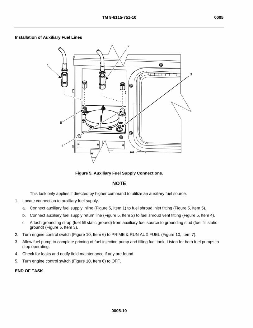
TM 9-6115-751-10 0005
Installation of Auxiliary Fuel Lines
Figure 5. Auxiliary Fuel Supply Connections.
NOTE
This task only applies if directed by higher command to utilize an auxiliary fuel source.
1. Locate connection to auxiliary fuel supply.
a. Connect auxiliary fuel supply inline (Figure 5, Item 1) to fuel shroud inlet fitting (Figure 5, Item 5).
b. Connect auxiliary fuel supply return line (Figure 5, Item 2) to fuel shroud vent fitting (Figure 5, Item 4).
c. Attach grounding strap (fuel fill static ground) from auxiliary fuel source to grounding stud (fuel fill static ground) (Figure 5, Item 3).
2. Turn engine control switch (Figure 10, Item 6) to PRIME & RUN AUX FUEL (Figure 10, Item 7).
3. Allow fuel pump to complete priming of fuel injection pump and filling fuel tank. Listen for both fuel pumps to stop operating.
4. Check for leaks and notify field maintenance if any are found.
5. Turn engine control switch (Figure 10, Item 6) to OFF.
END OF TASK
0005-10

TM 9-6115-751-10 0005
Installation of Load Cables
WARNING
Generator set operator is permitted to make connections to output terminal board only. Connections to load distribution points or equipment beyond the output box shall only be made by properly trained and authorized personnel. Failure to comply may cause injury or death to personnel.
1. Secure load information from higher command.
Figure 6. Installation of Load and Ground Cables.
0005-11
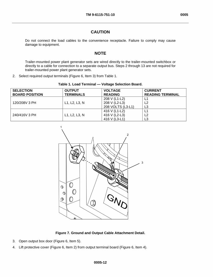
TM 9-6115-751-10 0005
CAUTION
Do not connect the load cables to the convenience receptacle. Failure to comply may cause damage to equipment.
NOTE
Trailer-mounted power plant generator sets are wired directly to the trailer-mounted switchbox or directly to a cable for connection to a separate output bus. Steps 2 through 13 are not required for trailer-mounted power plant generator sets.
2. Select required output terminals (Figure 6, Item 3) from Table 1.
Table 1. Load Terminal — Voltage Selection Board.
SELECTION BOARD POSITION
OUTPUT TERMINALS
VOLTAGE READING
CURRENT READING TERMINAL
120/208V 3 PH L1, L2, L3, N 208 V (L1-L2) 208 V (L2-L3) 208 VOLTS (L3-L1)
L1 L2 L3
240/416V 3 PH L1, L2, L3, N 416 V (L1-L2) 416 V (L2-L3) 416 V (L3-L1)
L1 L2 L3
Figure 7. Ground and Output Cable Attachment Detail.
3. Open output box door (Figure 6, Item 5).
4. Lift protective cover (Figure 6, Item 2) from output terminal board (Figure 6, Item 4).
0005-12
TM 9-6115-751-10 0005
0005-13
5. Remove terminal nut wrench (Figure 6, Item 6) from brackets on the inside of output box door (Figure 6, Item 5).
6. Loosen terminal nuts (Figure 7, Item 1) (shown removed for clarity) using terminal nut wrench (Figure 6, Item 6) on terminals selected from Table 1 in step 2.
7. Insert ends of load cables (Figure 6, Item 1) through flexible sleeve (Figure 2, Item 6).
8. Insert ends of load cables (Figure 6, Item 1) into slots (Figure 7, Item 3) of output terminals (Figure 6, Item 3) selected in step 2 from Table 1.
9. Tighten terminal nuts (Figure 6, Item 7 and Figure 7, Item 1).
10. Check ground cable (Figure 2, Item 7) connection to terminal (Figure 6, Item 3). Tighten as necessary.
11. Secure terminal nut wrench (Figure 6, Item 6) on the brackets inside of the output box door (Figure 6, Item 5).
12. Lower protective cover (Figure 6, Item 2) over output terminal board (Figure 6, Item 4).
13. Secure output box door (Figure 6, Item 5).
END OF TASK
INITIAL ADJUSTMENTS
1. Perform all Before PMCS procedures in IAW operator PMCS (WP 0013, PMCS).
2. Place voltage selection moveable board (Figure 8, Item 5) into position for output required by higher command.
WARNING
High voltage is produced when generator set is in operation. Never attempt to start the generator set unless it is properly grounded. Do not ground yourself in standing water. Never attempt to connect or disconnect load cables while the generator set is operating. Failure to comply may cause injury or death to personnel.
High voltage is produced when this generator set is in operation. Do not contact output cables when operating this generator set. Failure to comply may cause injury or death to personnel.
a. Secure load information from higher command.
b. Open output box door (Figure 6, Item 5).

TM 9-6115-751-10 0005
Figure 8. Configure Voltage Selection Board.
0005-14
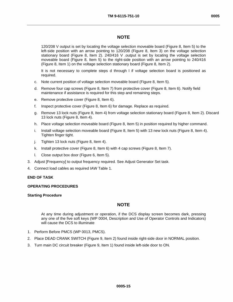
TM 9-6115-751-10 0005
0005-15
NOTE
120/208 V output is set by locating the voltage selection moveable board (Figure 8, Item 5) to the left-side position with an arrow pointing to 120/208 (Figure 8, Item 3) on the voltage selection stationary board (Figure 8, Item 2). 240/416 V .output is set by locating the voltage selection moveable board (Figure 8, Item 5) to the right-side position with an arrow pointing to 240/416 (Figure 8, Item 1) on the voltage selection stationary board (Figure 8, Item 2).
It is not necessary to complete steps d through l if voltage selection board is positioned as required.
c. Note current position of voltage selection moveable board (Figure 8, Item 5).
d. Remove four cap screws (Figure 8, Item 7) from protective cover (Figure 8, Item 6). Notify field maintenance if assistance is required for this step and remaining steps.
e. Remove protective cover (Figure 8, Item 6).
f. Inspect protective cover (Figure 8, Item 6) for damage. Replace as required.
g. Remove 13 lock nuts (Figure 8, Item 4) from voltage selection stationary board (Figure 8, Item 2). Discard 13 lock nuts (Figure 8, Item 4).
h. Place voltage selection moveable board (Figure 8, Item 5) in position required by higher command.
i. Install voltage selection moveable board (Figure 8, Item 5) with 13 new lock nuts (Figure 8, Item 4). Tighten finger tight.
j. Tighten 13 lock nuts (Figure 8, Item 4).
k. Install protective cover (Figure 8, Item 6) with 4 cap screws (Figure 8, Item 7).
l. Close output box door (Figure 6, Item 5).
3. Adjust [Frequency] to output frequency required. See Adjust Generator Set task.
4. Connect load cables as required IAW Table 1.
END OF TASK
OPERATING PROCEDURES
Starting Procedure
NOTE
At any time during adjustment or operation, if the DCS display screen becomes dark, pressing any one of the five soft keys (WP 0004, Description and Use of Operator Controls and Indicators) will cause the DCS to illuminate
1. Perform Before PMCS (WP 0013, PMCS).
2. Place DEAD CRANK SWITCH (Figure 9, Item 2) found inside right-side door in NORMAL position.
3. Turn main DC circuit breaker (Figure 9, Item 1) found inside left-side door to ON.

TM 9-6115-751-10 0005
Figure 9. Main DC Circuit Breaker and DEAD CRANK SWITCH.
4. Pull out EMERGENCY STOP (Figure 10, Item 3) on DCS.
0005-16
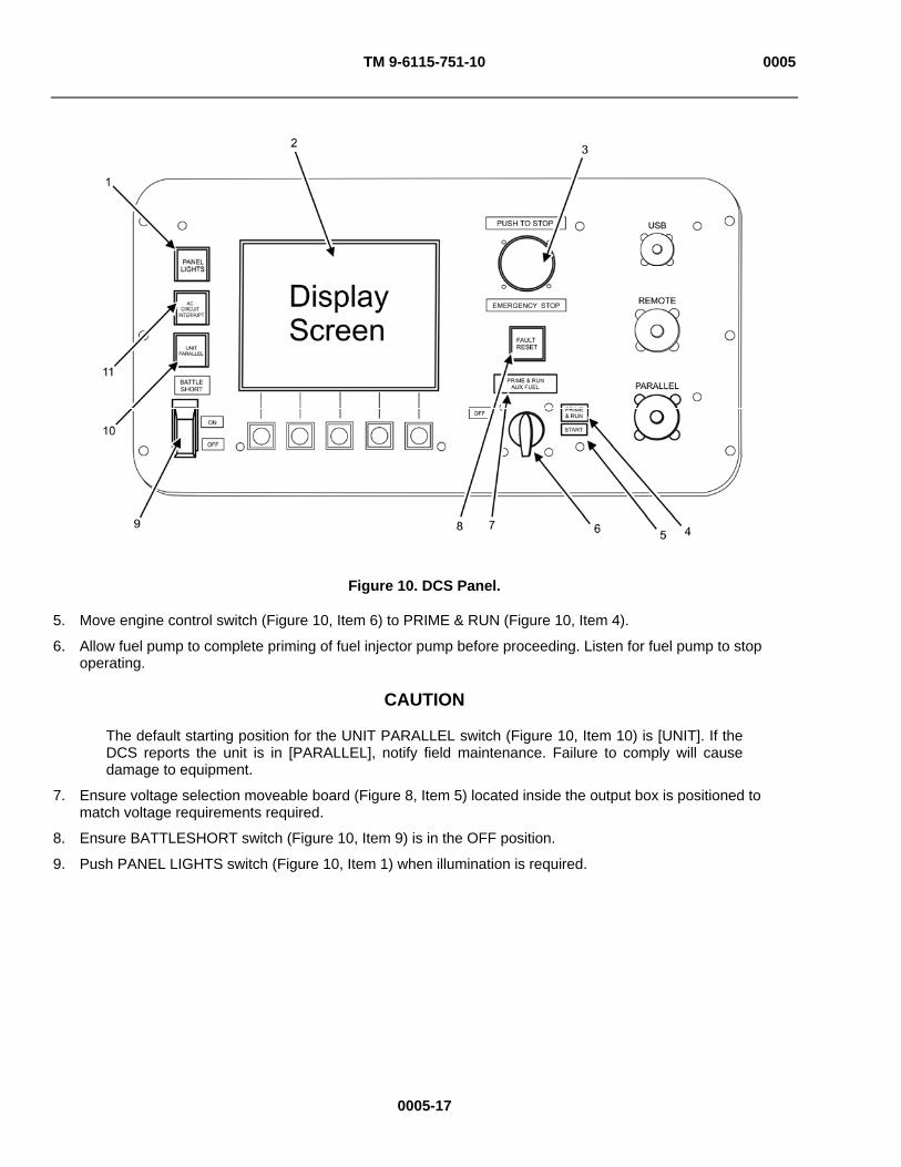
TM 9-6115-751-10 0005
0005-17
Figure 10. DCS Panel.
5. Move engine control switch (Figure 10, Item 6) to PRIME & RUN (Figure 10, Item 4).
6. Allow fuel pump to complete priming of fuel injector pump before proceeding. Listen for fuel pump to stop operating.
CAUTION
The default starting position for the UNIT PARALLEL switch (Figure 10, Item 10) is [UNIT]. If the DCS reports the unit is in [PARALLEL], notify field maintenance. Failure to comply will cause damage to equipment.
7. Ensure voltage selection moveable board (Figure 8, Item 5) located inside the output box is positioned to match voltage requirements required.
8. Ensure BATTLESHORT switch (Figure 10, Item 9) is in the OFF position.
9. Push PANEL LIGHTS switch (Figure 10, Item 1) when illumination is required.
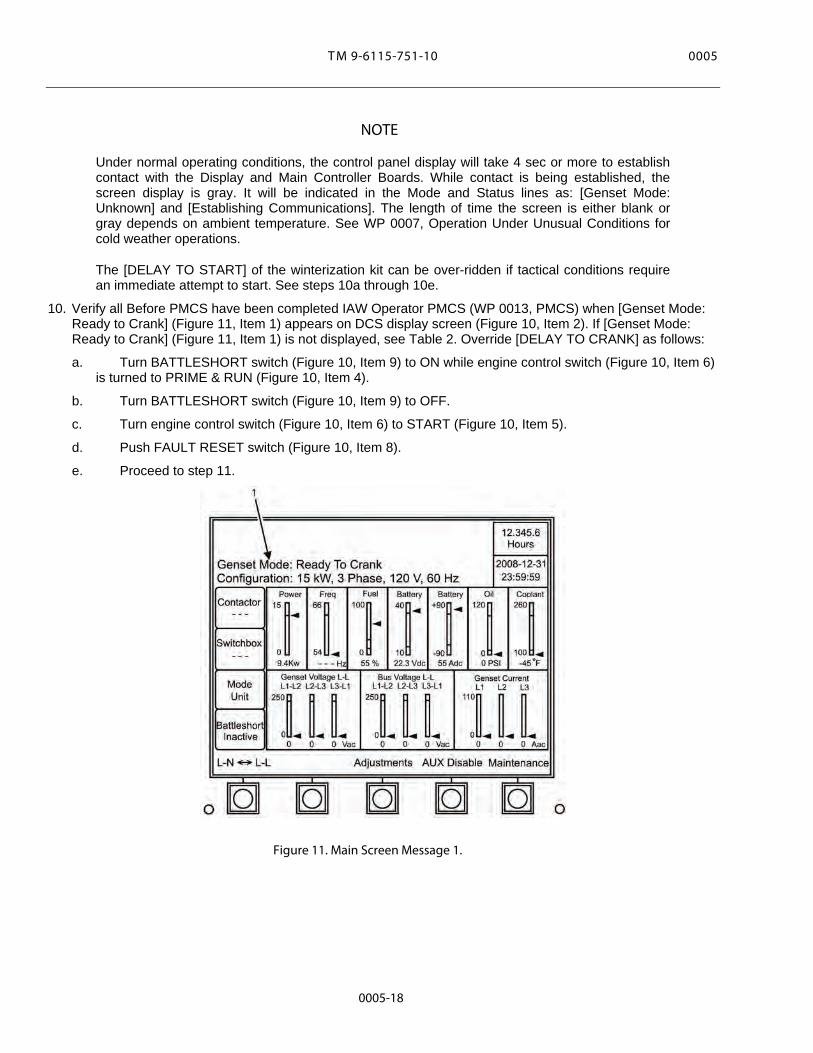
MT 5000 01-157-5116-9
NOTE
Under normal operating conditions, the control panel display will take 4 sec or more to establish contact with the Display and Main Controller Boards. While contact is being established, the screen display is gray. It will be indicated in the Mode and Status lines as: [Genset Mode: Unknown] and [Establishing Communications]. The length of time the screen is either blank or gray depends on ambient temperature. See WP 0007, Operation Under Unusual Conditions for cold weather operations.
The [DELAY TO START] of the winterization kit can be over-ridden if tactical conditions require an immediate attempt to start. See steps 10a through 10e.
10. Verify all Before PMCS have been completed IAW Operator PMCS (WP 0013, PMCS) when [Genset Mode: Ready to Crank] (Figure 11, Item 1) appears on DCS display screen (Figure 10, Item 2). If [Genset Mode: Ready to Crank] (Figure 11, Item 1) is not displayed, see Table 2. Override [DELAY TO CRANK] as follows:
a. Turn BATTLESHORT switch (Figure 10, Item 9) to ON while engine control switch (Figure 10, Item 6) is turned to PRIME & RUN (Figure 10, Item 4).
b. Turn BATTLESHORT switch (Figure 10, Item 9) to OFF.
c. Turn engine control switch (Figure 10, Item 6) to START (Figure 10, Item 5).
d. Push FAULT RESET switch (Figure 10, Item 8).
e. Proceed to step 11.
Figure 11. Main Screen Message 1.
0005-18

TM 9-6115-751-10 0005
NOTE
If [Genset Mode: Ready to Crank] (Figure 11, Item 1) does not appear within 15 min of indicated time, check DCS display screen (Figure 10, Item 2) for winterization kit faults and contact field maintenance.
The phrase “xx minutes” in table below is substituting for an unknown variable amount of time.
Table 2. Delay to Crank Messages.
MESSAGE(S) ACTION [Start-up Status: Delay To Crank—Wtr kit xx minutes] (Figure 12, Item 1) [Winterization kit: Not Ready to Crank] (Figure 12, Item 2)
Wait at least xx min. [Genset Mode: Ready to Crank] (Figure 11, Item 1) will appear. See WP 0010, Troubleshooting Procedures if not displayed after xx min.
[Start-up Status: Delay To Crank—Glow Plugs xx minutes] Wait at least xx min. [Genset Mode: Ready to Crank] (Figure 11, Item 1) will appear. See WP 0010, Troubleshooting Procedures if not displayed after xx min.
Figure 12. Main Screen Message 2.
11. Move engine control switch (Figure 10, Item 6) to START (Figure 10, Item 5).
12. Return engine control switch (Figure 10, Item 6) to PRIME & RUN (Figure 10, Item 4) or PRIME & RUN AUX FUEL (Figure 10, Item 7), as required.
0005-19

TM 9-6115-751-10 0005
NOTE
It is recommended to warm up engine without load for 5 min. However, load can be applied immediately as required.
13. Warm up engine without load for 5 min.
Figure 13. Operator Main Screen.
14. Check operator main screen for proper phase (Figure 13, Item 1), voltage (Figure 13, Item 2), and frequency (Figure 13, Item 3). Adjust as necessary. See Adjust Generator Set task.
15. Apply load by pushing AC CIRCUIT INTERRUPT switch (Figure 10, Item 11) on control panel once.
16. Observe main screen display for [Contactor Closed] indication which shows that generator set is now supplying power to the load.
17. Notify field maintenance if [Contactor Closed] does not display.
END OF TASK
0005-20
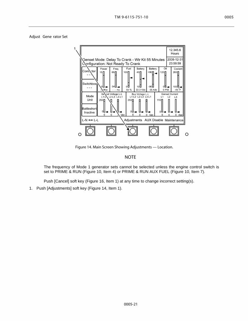
MT 5000 01-157-5116-9
Adjust Gene rator Set
Figure 14. Main Screen Showing Adjustments — Location.
NOTE
The frequency of Mode 1 generator sets cannot be selected unless the engine control switch is set to PRIME & RUN (Figure 10, Item 4) or PRIME & RUN AUX FUEL (Figure 10, Item 7).
Push [Cancel] soft key (Figure 16, Item 1) at any time to change incorrect setting(s).
1. Push [Adjustments] soft key (Figure 14, Item 1).
0005-21

TM 9-6115-751-10 0005
Figure 15. [Adjustments] Screen 1 — Select Option.
NOTE
Selected area will be highlighted on screen.
2. Push [ Previous] soft key (Figure 15, Item 1) or [Next ] soft key (Figure 15, Item 3) to scroll through [Adjustments] screen 1 options.
3. Push [Select] soft key (Figure 15, Item 2) to adjust desired option.
0005-22
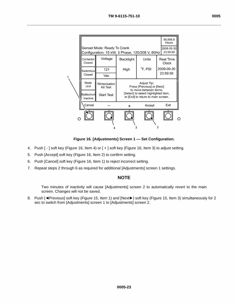
TM 9-6115-751-10 0005
Figure 16. [Adjustments] Screen 1 — Set Configuration.
4. Push [ - ] soft key (Figure 16, Item 4) or [ + ] soft key (Figure 16, Item 3) to adjust setting.
5. Push [Accept] soft key (Figure 16, Item 2) to confirm setting.
6. Push [Cancel] soft key (Figure 16, Item 1) to reject incorrect setting.
7. Repeat steps 2 through 6 as required for additional [Adjustments] screen 1 settings.
NOTE
Two minutes of inactivity will cause [Adjustments] screen 2 to automatically revert to the main screen. Changes will not be saved.
8. Push [ Previous] soft key (Figure 15, Item 1) and [Next ] soft key (Figure 15, Item 3) simultaneously for 2 sec to switch from [Adjustments] screen 1 to [Adjustments] screen 2.
0005-23
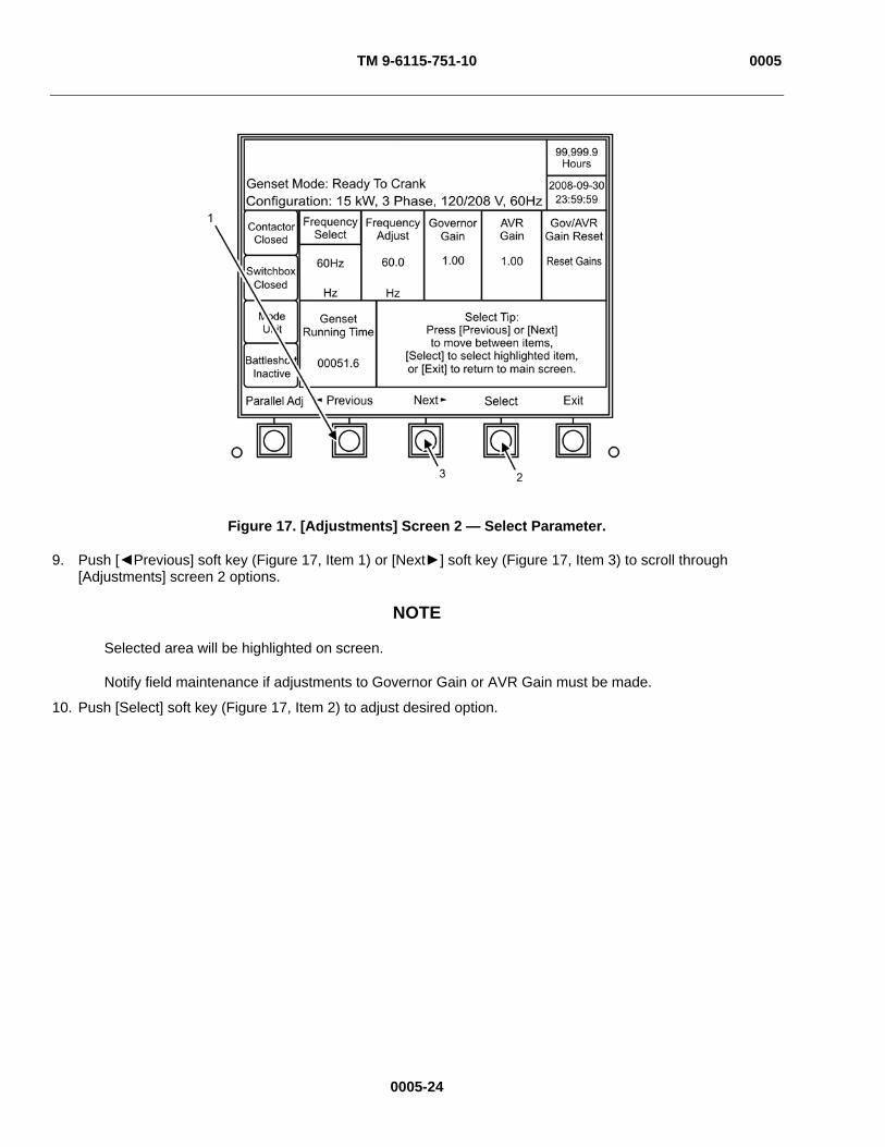
TM 9-6115-751-10 0005
Figure 17. [Adjustments] Screen 2 — Select Parameter.
9. Push [ Previous] soft key (Figure 17, Item 1) or [Next ] soft key (Figure 17, Item 3) to scroll through [Adjustments] screen 2 options.
NOTE
Selected area will be highlighted on screen.
Notify field maintenance if adjustments to Governor Gain or AVR Gain must be made.
10. Push [Select] soft key (Figure 17, Item 2) to adjust desired option.
0005-24
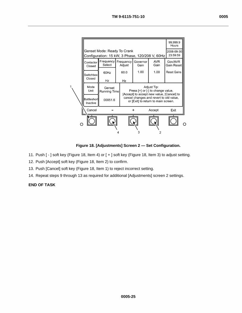
TM 9-6115-751-10 0005
Figure 18. [Adjustments] Screen 2 — Set Configuration.
11. Push [ - ] soft key (Figure 18, Item 4) or [ + ] soft key (Figure 18, Item 3) to adjust setting.
12. Push [Accept] soft key (Figure 18, Item 2) to confirm.
13. Push [Cancel] soft key (Figure 18, Item 1) to reject incorrect setting.
14. Repeat steps 9 through 13 as required for additional [Adjustments] screen 2 settings.
END OF TASK
0005-25

TM 9-6115-751-10 0005
Monitoring Generator Set Operational Status
Figure 19. Main Control Screen Status Indicators 120/208 V 3 Phase.
Table 3. Screen Indicator Parameters.
SCREEN INDICATOR UPPER MAXIMUM LIMIT LOWER MINIMUM LIMIT [Power] 18.0 kW 0 kW [Frequency] 50 Hz (UOC 98E) 51.5 Hz 48.5 Hz [Frequency] 60 Hz (UOC 98E) 61.98 Hz 58.2 Hz [Frequency] 400 Hz (UOC 98F) 412 Hz 388 Hz [Fuel] 100% 5% [Battery] 32 V 24 V [Battery] 90 Amp 0 Amp [Oil] 60 psi (413.7 kPa) 20 psi (137.9 kPa) [Coolant] 230°F (104°C) 185°F (85°C) [Voltage] [120/208 V], [3 Phase], [50 Hz]
122/212 V 114/189 V
[Voltage] [240/416 V], [3 Phase], [50 Hz]
244/425 V 228/379 V
[Voltage] [120/208 V], [3 Phase], [60 Hz]
126/240 V 114/205 V
[Voltage] [240/416 V], [3 Phase], [60 Hz]
252/479 V 228/394V
1. Perform all During PMCS (WP 0013, PMCS).
2. Monitor the following main control screen status indicators during operation. If outside prescribed limits (Table 3), perform troubleshooting procedures (WP 0010, Troubleshooting Procedures).
a. [Power] (Figure 19, Item 10).
b. [Frequency] (Figure 19, Item 3).
0005-26

TM 9-6115-751-10 0005
0005-27
c. [Fuel] (Figure 19, Item 4).
d. [Battery Vdc] Volts (Figure 19, Item 5).
e. [Battery Adc] Amperes (Figure 19, Item 6).
CAUTION
Operating the unit with low oil pressure may cause engine overheating and/or excessive engine wear. Avoid operating the unit with continued low oil pressure. Failure to comply will cause damage to equipment.
f. [Oil] (Figure 19, Item 7).
CAUTION
Operating the unit with extreme high or low coolant temperature may cause excessive engine wear and engine seizing. Do not operate the unit with continued high coolant temperature. Failure to comply will cause damage to equipment.
g. [Coolant] (Figure 19, Items 8 and 9).
NOTE
Faults and warnings (Figure 19, Items 1 and 2) are preceded by a code number and description. See (WP 0011, DCS Fault and Warning Codes and Descriptions) to determine operator authorization for handling warnings and/or fault codes. Warnings, if not addressed, will usually lead to faults. Faults normally cause unit to shut down. Attempt to resolve warnings and faults (WP 0010, Troubleshooting Procedures). Notify field maintenance if unable to resolve a fault or warning. Faults and warnings are displayed on the illustration for purposes of illustration: fault and warning parameters are not met on illustration.
3. Monitor status bar for faults and warnings (Figure 19, Items 1 and 2).
NOTE
Step 4 applies to all [Warning] codes except [Warning 3661: Active Maintenance Item] and to all [Fault] codes. Step 5 through step 9 applies only to [Warning 3661: Active Maintenance Item].
4. Troubleshoot the generator set (WP 0010, Troubleshooting Procedures) if [Fault] codes, [Warning] codes, or parameters other than those set are found.

TM 9-6115-751-10 0005
Figure 20. Select Maintenance Screen.
5. Select [Maintenance] screen if [Warning 3661: Active Maintenance Item] (Figure 20, Item 1) is shown in [Warning] display line of DCS by pushing [Maintenance] soft key (Figure 20, Item 2).
0005-28

TM 9-6115-751-10 0005
Figure 21. First Maintenance Screen.
6. Push [Maint Items] soft key (Figure 21, Item 1) to display [Active Maintenance Item] described (Figure 22, Item 1). Record information displayed.
0005-29

TM 9-6115-751-10 0005
Figure 22. Maintenance Item Display.
7. Push [Next] soft key (Figure 22, Item 2) to display and record [Next Service Due In xx Hours xxx xxx xxx] (Figure 23, Items 1 and 2) displayed. Record information.
0005-30

TM 9-6115-751-10 0005
Figure 23. Next Items Display.
8. Repeat step 7 until all service items [xxx xxx xxx] (Figure 23, Item 2) with less than 24 hours listed under [Next Service Due In xx Hours] (Figure 23, Item 1) have been displayed and recorded.
9. Notify field maintenance of all service items recorded.
END OF TASK
Operation with Remote Monitoring
1. Secure permission for remote monitoring from higher command.
NOTE
The AMMPS 15 kW generator sets provide limited remote operation capabilities. The operational status of generator set can be monitored, battleshort conditions can be set and released, and an emergency stop can be executed up to 250-ft (76.2-m) distance. The intent of remote operation capability is to permit the operator to monitor more than one unit at the same time and to be sheltered from severe environmental conditions. Loss of signal between remote monitoring site and generator set does not adversely affect generator set operation. Loss of signal between remote monitoring site and generator set will release [BATTLESHORT] setting at the generator set. The remote monitoring system connects to main control board, bypassing screen control board.
2. Perform all Before PMCS required (WP 0013, PMCS).
3. Start generator set. See Starting Procedure task.
4. Perform all During PMCS required (WP 0013, PMCS).
5. Ensure unit is operating at requested parameters. See Monitoring Generator Set Operational Status task.
0005-31

TM 9-6115-751-10 0005
NOTE
This cable and converter do not come with the generator set and must be ordered.
6. Insert remote control cable (Figure 24, Item 2) into REMOTE connector (Figure 24, Item 1) on DCS.
Figure 24. Operator Display Panel — Remote Connection.
7. Connect other end (Figure 25, Item 3) of remote control cable (Figure 25, Item 2) into suitable interface of IBM-compatible PC (Figure 25, Item 1).
8. Initialize IBM-compatible PC (Figure 25, Item 1).
0005-32
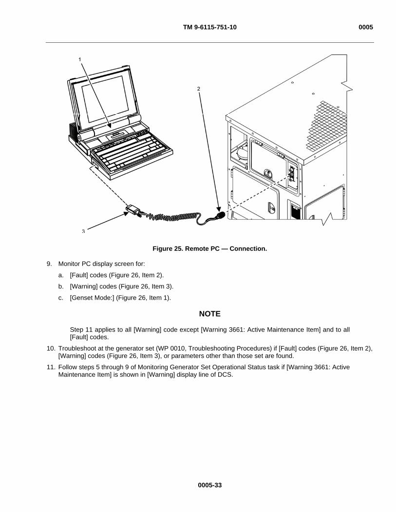
TM 9-6115-751-10 0005
Figure 25. Remote PC — Connection.
9. Monitor PC display screen for:
a. [Fault] codes (Figure 26, Item 2).
b. [Warning] codes (Figure 26, Item 3).
c. [Genset Mode:] (Figure 26, Item 1).
NOTE
Step 11 applies to all [Warning] code except [Warning 3661: Active Maintenance Item] and to all [Fault] codes.
10. Troubleshoot at the generator set (WP 0010, Troubleshooting Procedures) if [Fault] codes (Figure 26, Item 2), [Warning] codes (Figure 26, Item 3), or parameters other than those set are found.
11. Follow steps 5 through 9 of Monitoring Generator Set Operational Status task if [Warning 3661: Active Maintenance Item] is shown in [Warning] display line of DCS.
0005-33

TM 9-6115-751-10 0005
Figure 26. Remote PC Display.
12. Monitor PC display screen to ensure AC generator outputs remain within acceptable parameters.
a. [Genset Voltage] Line-to-Line [Lx-Lx] (Figure 26, Item 4) and Line-to-Neutral [Lx-N] (Figure 26, Item 16).
b. [Bus Voltage] [Lx-Lx] (Figure 26, Item 5) and [Lx-N] (Figure 26, Item 15).
0005-34

TM 9-6115-751-10 0005
0005-35
c. [Genset Current] Line-to-Line (Figure 26, Item 6).
d. [Genset Frequency] (Figure 26, Item 7).
e. [Bus Frequency] (Figure 26, Item 8).
f. [Power] (Figure 26, Item 9). Troubleshoot generator if parameters not met (WP 0010, Troubleshooting Procedures)
13. Monitor PC display screen for engine functions.
a. [Fuel Level] (Figure 26, Item 10).
b. [Battery Voltage] (Figure 26, Item 11).
c. [Battery Amps] (Figure 26, Item 12).
d. [Oil Pressure] (Figure 26, Item 13).
e. [Coolant Temperature] (Figure 26, Item 14).
14. Troubleshoot engine if not within required parameters (WP 0010, Troubleshooting Procedures).
NOTE [Battle Short Command] (Figure 26, Item 19) position will display [OFF] when battleshort is inactive and [ON] for active. The remote battleshort command is independent of the battleshort command on the DCS. It is possible to turn on the battleshort from the DCS. In this case, the [Battle Short] status field (Figure 26, Item 17) will transition to [Active] and the [Battle Short Command] (Figure 26, Item 19) position will remain in the [OFF] position.
15. Enable or disable battleshort as required by tactical conditions by placing PC cursor over [Battleshort Command] (Figure 26, Item 19) symbol and clicking mouse or pressing [Enter] on keyboard.
CAUTION
Do not allow the engine to operate with any of the monitored engine functions in the red area of the monitoring tapes unless specifically ordered to do so by higher command. Shut down the generator set using the remote emergency stop function or by utilizing the Stopping Procedure task. Failure to comply will cause damage to equipment.
NOTE
Both the remote [Emergency Stop] (Figure 26, Item 20) and the EMERGENCY STOP (Figure 10, Item 3) must be [OFF] to restart the engine while the remote monitor is active.
16. Enable or disable [Emergency Stop] (Figure 26, Item 20) as required by faulty engine/AC generator condition by placing PC cursor over [Emergency Stop] (Figure 26, Item 20) command symbol and clicking mouse or pressing [Enter] on keyboard. The [Emergency Stop] status display (Figure 26, Item 18) will show either [Stopped] or [Not Stopped]. The [Emergency Stop] (Figure 26, Item 20) command symbol will display either [OFF] or [ON].
17. Troubleshoot at generator set if [Emergency Stop] (Figure 26, Item 20) has been activated (WP 0010, Troubleshooting Procedures).
END OF TASK

TM 9-6115-751-10 0005
Stopping Procedure
Figure 27. Stopping Procedure.
1. Push AC CIRCUIT INTERRUPT switch (Figure 27, Item 1) to place generator contactor in [CONTACTOR OPEN] position.
NOTE
The engine can be shut down immediately after the load is removed. It is preferred that a cool down period of 5 min be allowed before engine shut down.
2. Allow generator set to operate for 5 min with no load applied.
3. Place engine control switch (Figure 27, Item 2) in OFF position.
4. Place DEAD CRANK SWITCH (Figure 9, Item 2) in OFF position.
5. Push in EMERGENCY STOP (Figure 10, Item 3).
6. Turn main DC circuit breaker (Figure 9, Item 1) to OFF/TRIP.
7. Perform all After PMCS (WP 0013, PMCS).
END OF TASK
0005-36

TM 9-6115-751-10 0005
DECALS AND INSTRUCTION PLATES
Identification and instructions plates are mounted on the generator set. Figure 28 through Figure 32 show the location and contents of each plate on each generator set. Table 4 through Table 8 identify the plates illustrated in Figure 33 through Figure 55.
Figure 28. Decals and Instruction Plates, Right-Side — Model 1050/1051.
Table 4. Decals and Instruction Plates, Right-Side — Model 1050/1051.
ITEM NUMBER NAME MODEL 1050
FIGURE NUMBER MODEL 1051
FIGURE NUMBER 1 Plate, Identification Figure 33 Figure 34 2 Name Plate, Identification Figure 35 Figure 36 3 Label, Lifting and Tie Down Figure 37 Figure 37 4 Plate, Individual Unit Identification (IUID) Figure 38 Figure 39 5 Plate, System Capacity Figure 40 Figure 40 6 Plate, Set Rating Figure 41 Figure 42
0005-37
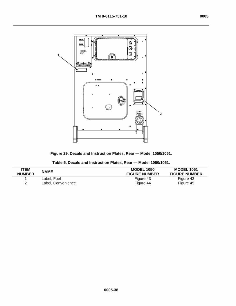
TM 9-6115-751-10 0005
Figure 29. Decals and Instruction Plates, Rear — Model 1050/1051.
Table 5. Decals and Instruction Plates, Rear — Model 1050/1051.
ITEM NUMBER NAME MODEL 1050
FIGURE NUMBER MODEL 1051
FIGURE NUMBER 1 Label, Fuel Figure 43 Figure 43 2 Label, Convenience Figure 44 Figure 45
0005-38
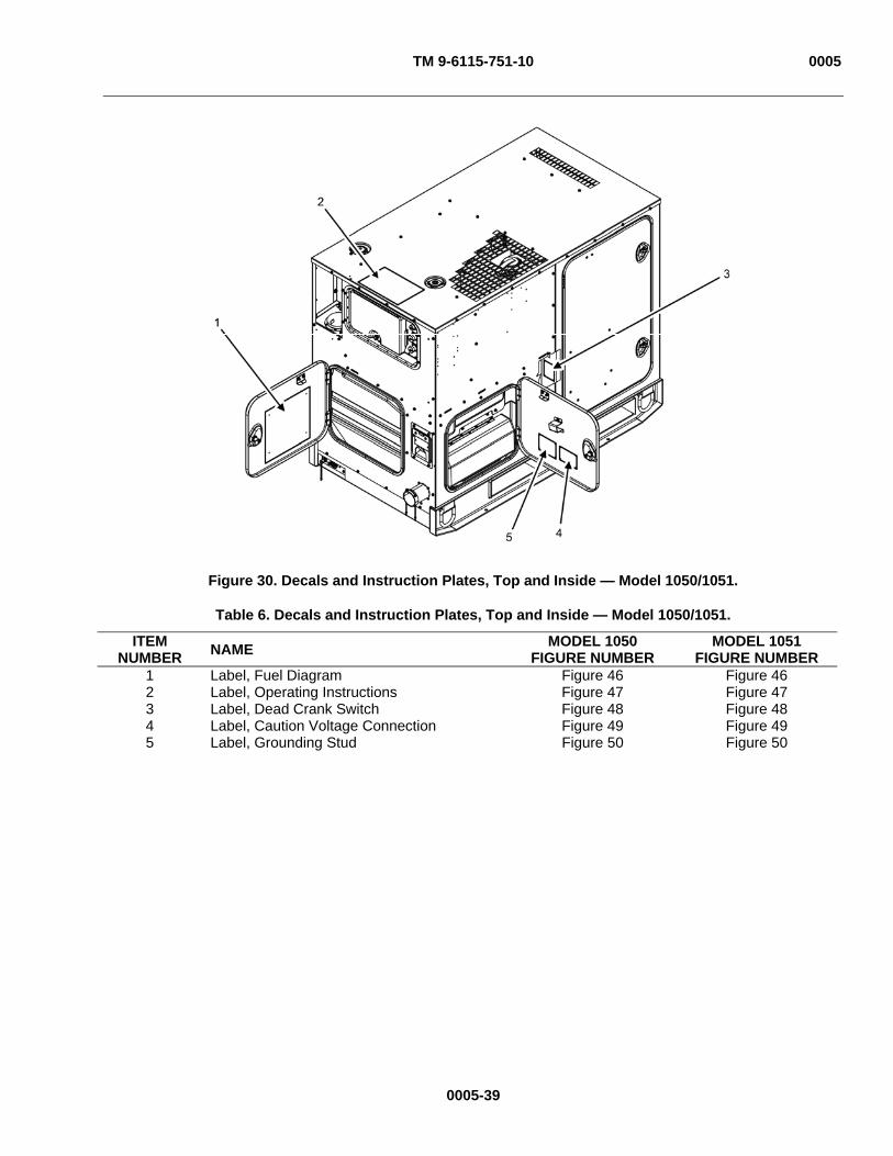
TM 9-6115-751-10 0005
Figure 30. Decals and Instruction Plates, Top and Inside — Model 1050/1051.
Table 6. Decals and Instruction Plates, Top and Inside — Model 1050/1051.
ITEM NUMBER NAME MODEL 1050
FIGURE NUMBER MODEL 1051
FIGURE NUMBER 1 Label, Fuel Diagram Figure 46 Figure 46 2 Label, Operating Instructions Figure 47 Figure 47 3 Label, Dead Crank Switch Figure 48 Figure 48 4 Label, Caution Voltage Connection Figure 49 Figure 49 5 Label, Grounding Stud Figure 50 Figure 50
0005-39
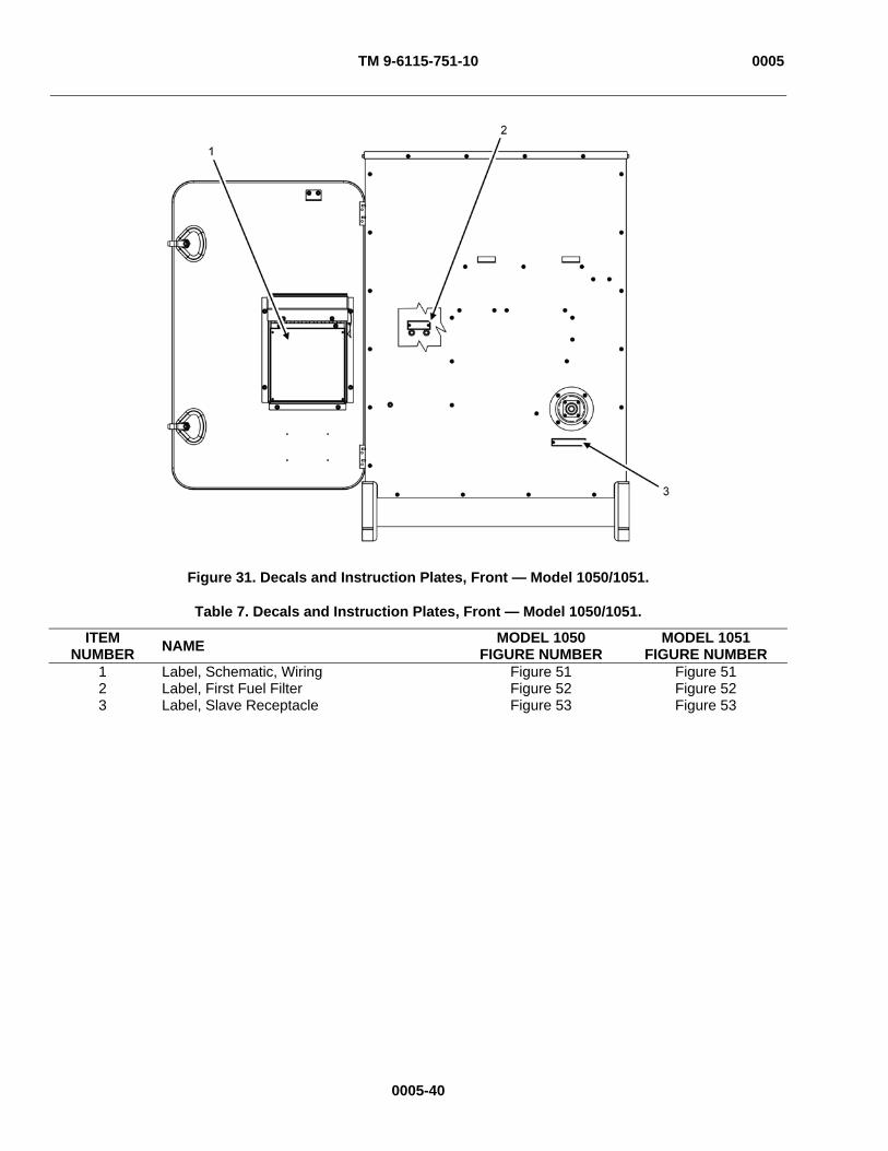
TM 9-6115-751-10 0005
Figure 31. Decals and Instruction Plates, Front — Model 1050/1051.
Table 7. Decals and Instruction Plates, Front — Model 1050/1051.
ITEM NUMBER NAME MODEL 1050
FIGURE NUMBER MODEL 1051
FIGURE NUMBER 1 Label, Schematic, Wiring Figure 51 Figure 51 2 Label, First Fuel Filter Figure 52 Figure 52 3 Label, Slave Receptacle Figure 53 Figure 53
0005-40
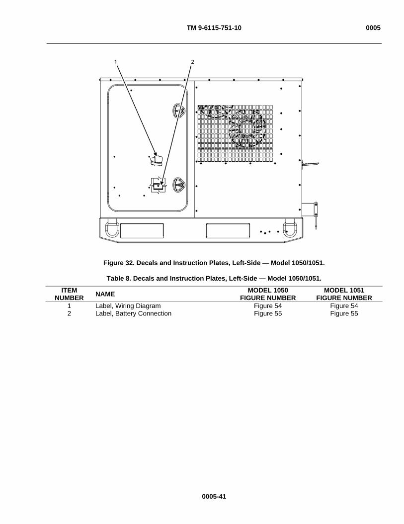
TM 9-6115-751-10 0005
Figure 32. Decals and Instruction Plates, Left-Side — Model 1050/1051.
Table 8. Decals and Instruction Plates, Left-Side — Model 1050/1051.
ITEM NUMBER NAME MODEL 1050
FIGURE NUMBER MODEL 1051
FIGURE NUMBER 1 Label, Wiring Diagram Figure 54 Figure 54 2 Label, Battery Connection Figure 55 Figure 55
0005-41

TM 9-6115-751-10 0005
Figure 33. Plate, Identification — Model 1050.
Figure 34. Plate, Identification — Model 1051.
0005-42

TM 9-6115-751-10 0005
Figure 35. Name Plate, Identification — Model 1050.
Figure 36. Name Plate, Identification — Model 1051.
0005-43

TM 9-6115-751-10 0005
Figure 37. Label, Lifting and Tie Down — Model 1050/1051.
Figure 38. Plate, IUID Identification — Model 1050.
0005-44
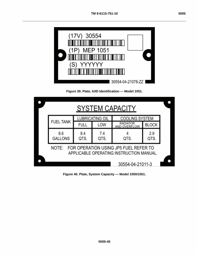
TM 9-6115-751-10 0005
Figure 39. Plate, IUID Identification — Model 1051.
Figure 40. Plate, System Capacity — Model 1050/1051.
0005-45

TM 9-6115-751-10 0005
Figure 41. Plate, Set Rating — Model 1050.
Figure 42. Plate, Set Rating — Model 1051.
0005-46
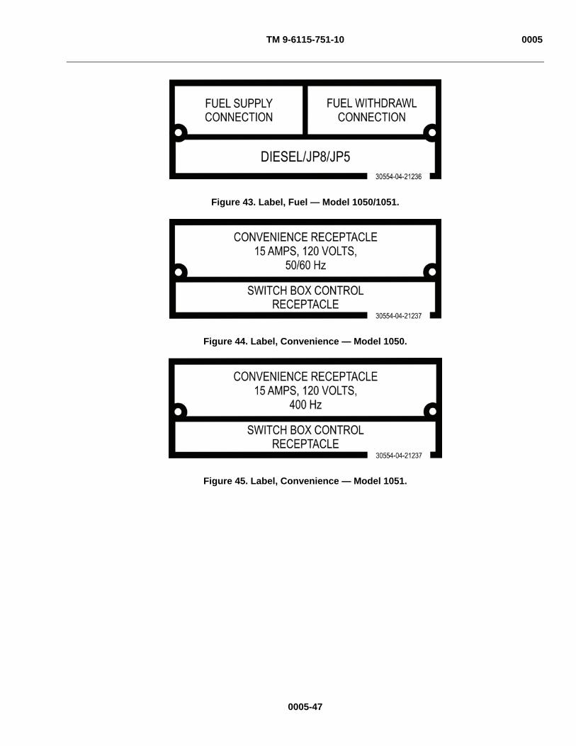
TM 9-6115-751-10 0005
Figure 43. Label, Fuel — Model 1050/1051.
Figure 44. Label, Convenience — Model 1050.
Figure 45. Label, Convenience — Model 1051.
0005-47

TM 9-6115-751-10 0005
Figure 46. Label, Fuel Diagram — Model 1050/1051.
0005-48

TM 9-6115-751-10 0005
Figure 47. Label, Operating Instructions — Model 1050/1051.
Figure 48. Label, Dead Crank — Model 1050/1051.
0005-49
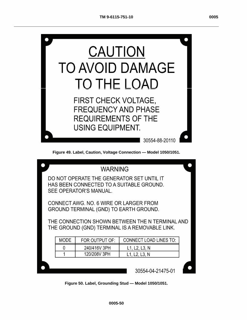
TM 9-6115-751-10 0005
Figure 49. Label, Caution, Voltage Connection — Model 1050/1051.
Figure 50. Label, Grounding Stud — Model 1050/1051.
0005-50

TM 9-6115-751-10 0005
Figure 51. Label, Diagram, Wiring — Model 1050/1051.
Figure 52. Label, First Fuel Filter — Model 1050/1051.
0005-51

TM 9-6115-751-10 0005
Figure 53. Label, Slave Receptacle — Model 1050/1051.
Figure 54. Label, Schematic, Wiring — Model 1050/1051.
0005-52
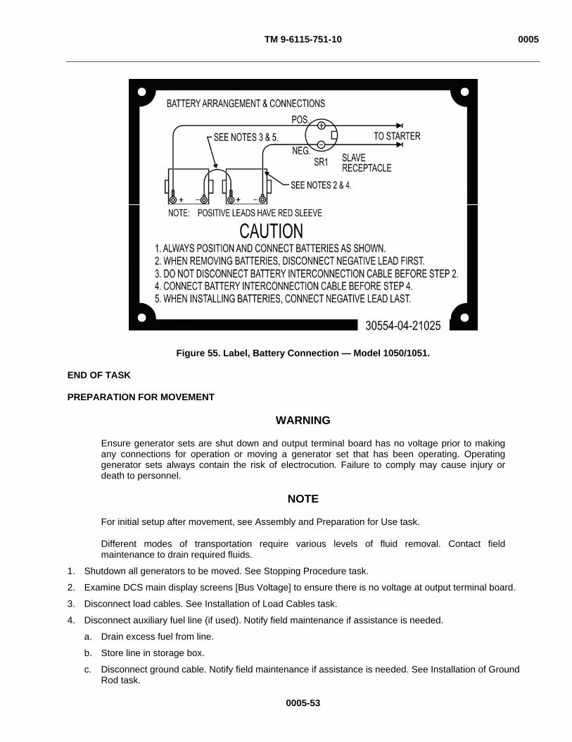
TM 9-6115-751-10 0005
Figure 55. Label, Battery Connection — Model 1050/1051.
END OF TASK
PREPARATION FOR MOVEMENT
WARNING
Ensure generator sets are shut down and output terminal board has no voltage prior to making any connections for operation or moving a generator set that has been operating. Operating generator sets always contain the risk of electrocution. Failure to comply may cause injury or death to personnel.
NOTE
For initial setup after movement, see Assembly and Preparation for Use task.
Different modes of transportation require various levels of fluid removal. Contact field maintenance to drain required fluids.
1. Shutdown all generators to be moved. See Stopping Procedure task.
2. Examine DCS main display screens [Bus Voltage] to ensure there is no voltage at output terminal board.
3. Disconnect load cables. See Installation of Load Cables task.
4. Disconnect auxiliary fuel line (if used). Notify field maintenance if assistance is needed.
a. Drain excess fuel from line.
b. Store line in storage box.
c. Disconnect ground cable. Notify field maintenance if assistance is needed. See Installation of Ground Rod task.
0005-53

TM 9-6115-751-10 0005
0005-54
5. Remove ground rods.
6. Store ground rods in storage rack inside left-side door of the generator set.
7. Store cable and couplings in storage box located inside right-side door.
8. Secure all generator set access doors and panels.
END OF TASK
END OF WORK PACKAGE
TM 9-6115-751-10 0006
0006-1
OPERATOR MAINTENANCE
AMMPS 15KW GENERATOR SET
PARALLEL OPERATION
INITIAL SETUP:
Test Equipment
Not Applicable
Tools and Special Tools
Not Applicable
Materials/Parts
Not Applicable
Personnel Required
Operator (1)
References
WP 0004, Description and Use of Operator Controls and Indicators
Equipment Condition
Engine control switch OFF (WP 0005, Operation Under Usual Conditions)
PARALLEL OPERATION
WARNING
DC voltages are present at generator set electrical components even with generator set shut down. Avoid shorting any positive with ground/negative. Do not ground yourself in standing water. Failure to comply may cause injury or death to personnel and damage to equipment.
High voltage is produced when generator set is in operation. Do not connect to a load that is not protected with appropriate safety devices. Do not connect from output terminal board to output terminal board unless directed by higher command. Never attempt to start the generator set unless it is properly grounded. Do not ground yourself in standing water. Never attempt to connect or disconnect load cables while the generator set is operating. Do not contact output cables when operating this generator set. Make sure that the connection between generator set and load is completely deenergized (safety device opens circuit) prior to disconnecting load cables or performing maintenance on the output terminal board. Failure to comply may cause injury or death to personnel.
Ensure generator sets are shut down and output terminal board has no voltage prior to making any connections for parallel operation or moving a generator set that has been operating in parallel. Operating generator sets always contain the risk of electrocution. Failure to comply may cause injury or death to personnel.
Exhaust discharge contains deadly gases, including carbon monoxide. Exhaust gases are most dangerous in places with poor ventilation. Do not operate generator set in an enclosed area unless exhaust discharge is properly vented. Failure to comply may cause injury or death to personnel.
When operating, generator set engine has hot metal surfaces that will burn flesh on contact. Shut down generator set and allow engine to cool before checks, services, and maintenance. Wear gloves and additional protective clothing as required. Failure to comply may cause injury or death to personnel.

TM 9-6115-751-10 0006
0006-2
Connecting Generator Sets Parallel Cables (Power Plant Configuration)
WARNING
High voltage is produced when generator set is in operation. Never attempt to start the generator set unless it is properly grounded. Do not ground yourself in standing water. Never attempt to connect or disconnect load cables while the generator sets are operating. Failure to comply may cause injury or death to personnel.
High-voltage power is available when the main contactor is closed. Avoid accidental contact with live components. Ensure load cables are properly connected and the load cable door is shut before closing main contactor. Ensure that personnel working with/on loads connected to the generator set are aware that main contactor is about to be closed before closing main contactor. Failure to comply may cause injury or death to personnel.
Generator set operator is permitted to make connections to output terminal board only. Connections to load distribution points or to equipment beyond the output terminal board shall only be made by properly trained and authorized personnel. Failure to comply may cause injury or death to personnel.
CAUTION
All generator sets to be operated in parallel must be of the same capacity and selected for the same voltage and frequency. Failure to comply will cause damage to equipment.
Ensure the load requirement is equal to or less than the combined rated capacity of the two or more generator sets. Failure to comply will cause damage to equipment.
NOTE
Output requirements will be given to the operator prior to operation.
1. Obtain load information and paralleling requirements from higher command.
CAUTION
For 50/60 Hz generator sets, ensure that both generator set frequency selections are positioned for the same load requirements. Failure to match the settings will result in damage to the load equipment being supplied by the generator set. Failure to comply will cause damage to equipment.
2. Ensure adjustments are set for the generator sets’ required output (WP 0005, Operation Under Usual Conditions) of both [Freq] (Figure 4, Item 2) and [Genset Voltage] (either [L-N] or [L-L]) (Figure 4, Item 1).
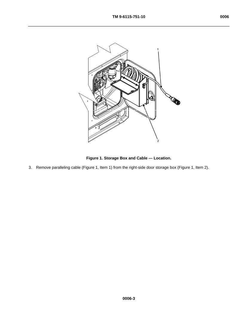
TM 9-6115-751-10 0006
Figure 1. Storage Box and Cable — Location.
3. Remove paralleling cable (Figure 1, Item 1) from the right-side door storage box (Figure 1, Item 2).
0006-3
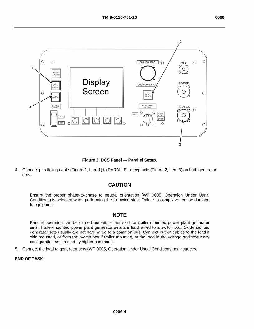
TM 9-6115-751-10 0006
Figure 2. DCS Panel — Parallel Setup.
4. Connect paralleling cable (Figure 1, Item 1) to PARALLEL receptacle (Figure 2, Item 3) on both generator sets.
CAUTION
Ensure the proper phase-to-phase to neutral orientation (WP 0005, Operation Under Usual Conditions) is selected when performing the following step. Failure to comply will cause damage to equipment.
NOTE Parallel operation can be carried out with either skid- or trailer-mounted power plant generator sets. Trailer-mounted power plant generator sets are hard wired to a switch box. Skid-mounted generator sets usually are not hard wired to a common bus. Connect output cables to the load if skid mounted, or from the switch box if trailer mounted, to the load in the voltage and frequency configuration as directed by higher command.
5. Connect the load to generator sets (WP 0005, Operation Under Usual Conditions) as instructed.
END OF TASK
0006-4

TM 9-6115-751-10 0006
Parallel Operation with Switch Box (Two Like Sets)
CAUTION
When generator sets are configured for parallel operation, the amperage capacity of interconnecting cables and switch box(es) must be of sufficient capacity to safely distribute the combined amperage of the generator sets connected together in parallel. Failure to comply may result in damage to equipment.
1. Connect generator sets (units A and B) parallel cables in PP configuration for both units to be operated together as a PP. See Connecting Generator Sets Parallel Cables (PP Configuration) task.
2. Make output cable connections between generator sets (units A and B) and switch boxes if necessary.
CAUTION
During examination of connectors and connector parts, note the position of alignment mating surfaces to ensure that when connectors are assembled to plugs they are in correct orientation. Failure to comply may cause damage to equipment.
NOTE
Step 3 and step 4 are required only if generator switch box cables were disconnected and removed following a previous period of operation.
3. Remove dust cap(s) from switch box contactor cable(s) (Figure 3, Item 3) and examine for evidence of foreign material, signs of corrosion, and damaged and/or missing connector parts.
Figure 3. Switch Box Contactor Receptacle.
0006-5
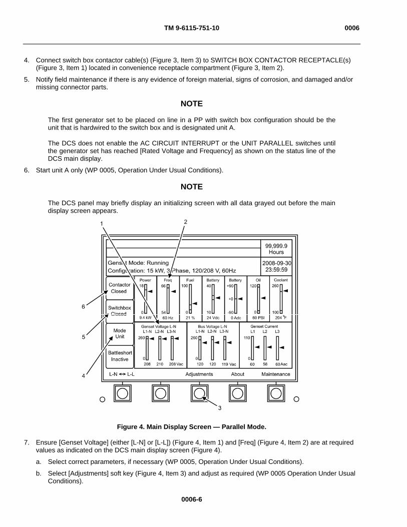
TM 9-6115-751-10 0006
4. Connect switch box contactor cable(s) (Figure 3, Item 3) to SWITCH BOX CONTACTOR RECEPTACLE(s) (Figure 3, Item 1) located in convenience receptacle compartment (Figure 3, Item 2).
5. Notify field maintenance if there is any evidence of foreign material, signs of corrosion, and damaged and/or missing connector parts.
NOTE
The first generator set to be placed on line in a PP with switch box configuration should be the unit that is hardwired to the switch box and is designated unit A.
The DCS does not enable the AC CIRCUIT INTERRUPT or the UNIT PARALLEL switches until the generator set has reached [Rated Voltage and Frequency] as shown on the status line of the DCS main display.
6. Start unit A only (WP 0005, Operation Under Usual Conditions).
NOTE
The DCS panel may briefly display an initializing screen with all data grayed out before the main display screen appears.
Figure 4. Main Display Screen — Parallel Mode.
7. Ensure [Genset Voltage] (either [L-N] or [L-L]) (Figure 4, Item 1) and [Freq] (Figure 4, Item 2) are at required values as indicated on the DCS main display screen (Figure 4).
a. Select correct parameters, if necessary (WP 0005, Operation Under Usual Conditions).
b. Select [Adjustments] soft key (Figure 4, Item 3) and adjust as required (WP 0005 Operation Under Usual Conditions).
0006-6

TM 9-6115-751-10 0006
0006-7
CAUTION
If [Running — Synchronized] does not display, do not proceed to step 9. Notify field maintenance of problem. Failure to comply will cause damage to equipment.
NOTE
Immediately following step 8, [Genset Mode] line of DCS will first display [Running — Synchronizing]. After a brief delay, [Running — Synchronized] should display.
8. Push UNIT PARALLEL switch (Figure 2, Item 4) until [Parallel] mode (Figure 4, Item 4) and [Switchbox] (Figure 4, Item 5) [Closed] message is displayed on unit A.
CAUTION
If [Running — Load Share] or [Contactor Closed] does not display immediately following step 9, contact field maintenance for direction on continuing operation. Failure to comply may cause damage to equipment.
NOTE
Immediately following step 9, [Genset Mode] line of DCS should display [Running — Load Share]. The [Contactor] display (Figure 4, Item 6) of the DCS should display [Closed].
9. Push and hold AC CIRCUIT INTERRUPT switch (Figure 2, Item 1) until DCS [Genset Mode] changes to [Running — Load Share].
10. Start second generator set (unit B) (WP 0005, Operation Under Usual Conditions).
NOTE
The DCS display may briefly display an initializing screen with all data grayed out before the main screen appears.
11. Ensure [Genset Voltage] (either [L-N] or [L-L]) (Figure 4, Item 1) and [Freq] (Figure 4, Item 2) are at required values as indicated on the DCS main display screen.
a. Select correct parameters, if necessary (WP 0005, Operation Under Usual Conditions).
b. Select [Adjustments] soft key (Figure 4, Item 3) and adjust as required (WP 0005, Operation Under Usual Conditions).
CAUTION
If [Running — Synchronized] does not display immediately following step 12, do not proceed to step 13. Notify field maintenance of problem. Failure to comply will cause damage to equipment.
NOTE
Immediately following step 12, [Genset Mode] line of DCS will first display [Running — Synchronizing]. After a brief delay, [Running — Synchronized] should display
12. Push UNIT PARALLEL switch (Figure 2, Item 4) until [Parallel] mode ((Figure 4, Item 4) and [Switchbox] (Figure 4, Item 5) [Closed] message is displayed on unit B.
TM 9-6115-751-10 0006
0006-8
CAUTION
If [Running — Load Share] or [Contactor Closed] does not display immediately following step 13, contact field maintenance for direction on continuing operation. Failure to comply may cause damage to equipment.
NOTE
Immediately following step 13, [Genset Mode] line of DCS should display [Running — Load Share]. The [Contactor] display of the DCS should display [Closed]. If [Running — Load Share] or [Contactor Closed] does not display, notify field maintenance.
13. Push and hold AC CIRCUIT INTERRUPT switch (Figure 2, Item 1) until DCS [Genset Mode] changes to [Running — Load Share].
END OF TASK
Parallel Operation Without Switch Box (Two Or More Like Sets)
1. Connect generator sets’ parallel cables in power plant configuration. See Connecting Generator Sets Parallel Cables (Power Plant Configuration) task for all generator sets to be operated together as a PP.
CAUTION
When generators are operated in parallel without a switch box, pay careful attention to the settings of each generator set and to the phase-to-phase connection of the load cables. Ensure the combined capacity of the units is sufficient to carry the required load. Failure to comply will cause damage to equipment.
NOTE
Designation of unit A or B, etc., is variable and dependant on the order they are placed online when used in PP configuration without a switch box.
2. Start generator set unit A (WP 0005, Operation Under Usual Conditions).
3. Ensure [Genset Voltage] (either [L-N] or [L-L]) (Figure 4, Item 1) and [Freq] (Figure 4, Item 2) are at required values as indicated on the DCS main display screen.
a. Select correct parameters, if necessary (WP 0005, Operation Under Usual Conditions).
b. Select [Adjustments] soft key (Figure 4, Item 3) and adjust as required.
TM 9-6115-751-10 0006
0006-9
CAUTION
If [Running — Synchronized] does not display immediately following step 4, do not proceed to step 5. Notify field maintenance of problem. Failure to comply will cause damage to equipment.
NOTE
The following sequence occurs after executing step 4. The generator automatically attempts to close switch box contactor to detect the condition of the output bus. Because this is the first generator on the output bus and the output bus is deenergized and there is not a switch box, the DCS will first display in the [Genset Mode] line of DCS [Running — Synchronizing]. After a brief delay, [Running — Synchronized] should display.
4. Push UNIT PARALLEL switch (Figure 2, Item 4) until [Parallel] mode (Figure 4, Item 4) and [Switchbox] (Figure 4, Item 5) [Open] message is displayed on unit A.
CAUTION
If [Running — Load Share] or [Contactor Closed] does not display immediately following step 5, contact field maintenance for direction on continuing operation. Failure to comply may cause damage to equipment.
NOTE
Immediately following step 5, [Genset Mode] line of DCS should display [Running — Load Share]. The [Contactor] display of the DCS should display [Closed].
After step 5, having found no switch box in this configuration, the DCS will issue a warning to the user: [Warning 3658: Switch Box Fail to Close]. Operation will not be stopped, allowing the operator to verify that the operation should continue. This warning cannot be cleared until the generator set has been shut down. Before generator set is to be restarted, push FAULT RESET (Figure 2, Item 2) to clear the warning. At this point the entire load is being carried by unit A.
5. Push and hold AC CIRCUIT INTERRUPT switch (Figure 2, Item 1) until DCS [Genset Mode] changes to [Running — Load Share].
6. Start second generator set (unit B) (WP 0005, Operation Under Usual Conditions).
7. Ensure [Genset Voltage] (either [L-N] or [L-L]) (Figure 4, Item 1) and [Freq] (Figure 4, Item 2) are at required values as indicated on the DCS main display screen.
a. Select correct parameters, if necessary (WP 0005, Operation Under Usual Conditions).
b. Select [Adjustments] soft key (Figure 4, Item 3) and adjust as required (WP 0005, Operation Under Usual Conditions).

TM 9-6115-751-10 0006
0006-10
CAUTION
Step 8 must be completed before step 9 for each generator set placed in parallel. Failure to comply will cause damage to equipment.
If [Running — Synchronized] does not display immediately following step 8, do not proceed to step 9. Notify field maintenance of problem. Failure to comply will cause damage to equipment.
NOTE
There is no switchbox in this configuration. The DCS will detect the condition of the bus directly. The generator set automatically attempts to close switch box contactor to detect the condition of the output bus. Since generator set unit A is already on the bus, generator set unit B will begin the synchronization sequence. The DCS will first display in the [Genset Mode] line of DCS [Running — Synchronizing]. After a brief delay, [Running — Synchronized] should display.
8. Push UNIT PARALLEL switch (Figure 2, Item 4) until [Parallel] mode (Figure 4, Item 4) and [Switchbox] (Figure 4, Item 5) [Open] message is displayed on unit B.
CAUTION
If [Running — Load Share] or [Contactor Closed] does not display immediately following step 9, contact field maintenance for direction on continuing operation. Failure to comply may cause damage to equipment.
NOTE
Immediately following step 9, [Genset Mode] line of DCS should display [Running — Load Share]. The [Contactor] display of the DCS should display [Closed].
After step 9, having found no switch box in this configuration, the DCS will issue a warning to the user: [Warning 3658: Switch Box Fail to Close]. Operation will not be stopped, allowing the operator to verify that the operation should continue. This warning cannot be cleared until the generator set has been shut down. Before generator set is to be restarted, push FAULT RESET (Figure 2, Item 2) to clear the warning. At this point, the load is being shared between unit A and unit B.
9. Push and hold AC CIRCUIT INTERRUPT switch (Figure 2, Item 1) until DCS [Genset Mode] changes to [Running — Load Share].
10. Repeat steps 6 through 9 for each additional generator set to be operated in parallel.
END OF TASK

TM 9-6115-751-10 0006
Adjusting Parallel Operations
CAUTION
Units operating in parallel should share the output load equally. Any variation from equal load sharing exceeding 2% should be corrected. Unequal load sharing may cause excessive wear to the generator set. Failure to comply may cause damage to equipment.
Before the first use of two or more generator sets in a power plant configuration, steps 1 through 11 should be completed to insure mechanical balance for parallel operation. Unequal load sharing may cause excessive wear to the generator set. Repeat these steps when an additional generator set or replacement generator set is added to the power plant. Failure to comply may cause damage to equipment.
NOTE
Contact field maintenance to perform adjustments.
All adjustments can be returned to prior setting after change by pushing [Cancel] soft key (Figure 6, Item 7). Pushing [Exit] soft key (Figure 6, Item 4) before accepting changes will return to main screen and adjustments will not be saved.
Screen navigated to will be highlighted with white background and black type.
Figure 5. Parallel Adjustment Screen, A.
1. Connect all generator sets in power plant configuration with paralleling cables. See Connecting Generator Sets Parallel Cables (Power Plant Configuration) task.
2. Connect all units to a switch box if available.
0006-11

TM 9-6115-751-10 0006
0006-12
3. Start all generator sets (WP 0005, Operation Under Usual Conditions) to be operated in parallel.
NOTE
This operation requires there be no load placed on the bus.
4. Place all generator sets into parallel operation. See Parallel Operation with Switch Box (Two Like Sets) task or Parallel Operation without Switch Box (Two Or More Like Sets) task without load.
5. Monitor all generator sets operating in parallel for [Total KW] (Figure 5, Item 5) in adjust parallel screen.
a. Push [Adjustments] soft key in main display screen (WP 0005, Operation Under Usual Conditions).
b. Push [ Previous] and [Next ] simultaneously for 2 sec to switch from [Adjustments] screen 1 to [Adjustments] screen 2 (WP 0005, Operation Under Usual Conditions).
c. Push [Parallel Adj] soft key to reach parallel adjustment display screen (WP 0004, Description and Use of Operator Controls and Indicators) from [Adjustments] screen 2.
NOTE
If a zero value is shown for [Total KW] (Figure 5, Item 5), the generator sets are in balance and no adjustments are necessary.
d. Record [Total KW] (Figure 5, Item 5) on all generators.
6. Adjust [KW Offset] (Figure 5, Item 1) or any generator set showing a value (positive or negative) for [Total KW] (Figure 5, Item 5).
a. Return to parallel adjustment screen (Steps 5a through 5c).
b. Navigate to [KW Offset] (Figure 5, Item 1) by pushing [Next ] soft key (Figure 5, Item 3) until [KW Offset] (Figure 5, Item 1) is highlighted.
c. Push [Select] soft key (Figure 5, Item 2) to enable adjustments.
d. Adjust the value of [KW Offset] (Figure 5, Item 1) until the average [Total KW] (Figure 5, Item 5) on all generator sets is zero.
NOTE
A combination of positive and negative adjustments may be made in step 6d. Adjustments on both sides of the decimal point can be made. It is not necessary in all situations to make such adjustments; however, the system requires that you navigate to both the right (Figure 6, Item 2) and left (Figure 6, Item 1) sides of the decimal point before accepting the changes made utilizing the [Next ] soft key (Figure 5, Item 3) and [Accept] soft key (Figure 8, Item 4) as they appear.
(1) Increase the value of [KW Offset] (Figure 5, Item 1) for any generator set with a positive value for [Total KW] (Figure 5, Item 5) by pushing the [ + ] soft key (Figure 6, Item 5) or decrease the value of [KW Offset] (Figure 5, Item 1) for any generator set with a negative value for [Total KW] (Figure 5, Item 5) by pushing the [ - ] soft key (Figure 6, Item 6).
(2) Shift to the right (Figure 6, Item 2) of the decimal point by selecting [Next ] soft key (Figure 5, Item 3), or return to the left (Figure 6, Item 1) of the decimal point by selecting [ Previous] soft key (Figure 7, Item 1), as necessary.
(3) Select [Next ] soft key (Figure 5, Item 3) from the farthest right-hand digit (Figure 8, Item 2) when desired value is attained.
(4) Select [Accept] soft key (Figure 8, Item 4) to commit desired value.

TM 9-6115-751-10 0006
Figure 6. Parallel Adjustment Screen, B.
7. Monitor all generator sets operating in parallel for [Total KVAR] (Figure 5, Item 4) in adjust parallel screen.
a. Push [Adjustments] soft key in main display screen (WP 0005, Operation Under Usual Conditions).
b. Push [ Previous] and [Next ] simultaneously for 2 sec to switch from [Adjustments] screen 1 to [Adjustments] screen 2 (WP 0005, Operation Under Usual Conditions).
c. Push [Parallel Adj] soft key to reach parallel adjustment display screen (WP 0004, Description and Use of Operator Controls and Indicators) from [Adjustment] screen 2.
NOTE
If a zero value is shown for [Total KVAR] (Figure 5, Item 4), the generator sets are in balance and no adjustments are necessary.
d. Record [Total KVAR] (Figure 5, Item 4) on all generators.
8. Adjust [KVAR Offset] (Figure 6, Item 3) for any generator set showing a value (positive or negative) for [Total KVAR] (Figure 5, Item 4).
a. Return to parallel adjustment screen. See steps 7a through 7c.
b. Navigate to [KVAR Offset] (Figure 6, Item 3) by pushing [Next ] soft key (Figure 5, Item 3) until [KVAR Offset] (Figure 6, Item 3) is highlighted.
c. Push [Select] soft key (Figure 5, Item 2) to enable adjustments.
d. Adjust the value of [KVAR Offset] (Figure 6, Item 3) until the average [Total KVAR] (Figure 5, Item 4) on all generator sets is zero.
0006-13

TM 9-6115-751-10 0006
0006-14
NOTE
A combination of positive and negative adjustments may be made in step 8d. Adjustments on both sides of the decimal point can be made. It is not necessary in all situations to make such adjustments. However, the system requires that you navigate to both the right and left sides of the decimal point before accepting the changes made utilizing the [Next ] soft key (Figure 5, Item 3) and [Accept] soft key (Figure 8, Item 4) as they appear.
(1) Increase the value of [KVAR Offset] (Figure 6, Item 3) for any generator set with a positive value for [Total KVAR] (Figure 5, Item 4) by pushing the [ + ] soft key (Figure 6, Item 5) or decrease the value of [KVAR Offset] (Figure 6, Item 3) for any generator set with a negative value for [Total KVAR] (Figure 5, Item 4) by pushing the [ - ] soft key (Figure 6, Item 6).
(2) Shift to the right (Figure 6, Item 2) decimal points by selecting [Next ] soft key (Figure 5, Item 3) or shift to the left decimal points by selecting [ Previous] soft key (Figure 7, Item 1), as necessary.
(3) Select [Next ] soft key (Figure 5, Item 3) from the farthest right-hand digit (Figure 8, Item 2) when desired value is attained.
(4) Select [Accept] soft key (Figure 8, Item 4) to commit desired value.
CAUTION
The maximum range of adjustment for [KVAR Offset] (Figure 6, Item 3) is ± 5%. If the maximum [KVAR Offset] (Figure 6, Item 3) has been reached and the generator sets have not reached zero [Total KVAR] (Figure 5, Item 4), do not apply load and notify field maintenance. Failure to comply may cause damage to equipment.
9. Push [Reset Offsets] (Figure 7, Item 3) to set both [KW Offset] (Figure 5, Item 1) and [KVAR Offset] (Figure 6, Item 3) to zero if unable to achieve balance.
a. Navigate to [Reset Offsets] (Figure 7, Item 3) using the [Next ] soft key (Figure 5, Item 3).
b. Push [Select] soft key (Figure 5, Item 2).
c. Push [Accept] soft key (Figure 8, Item 4).
d. Offsets are now restored to original values.
e. Notify field maintenance of failure to achieve mechanical balance.
10. Push [EXIT] soft key (Figure 6, Item 4) to return to main screen.
11. Apply load if able to achieve mechanical balance.
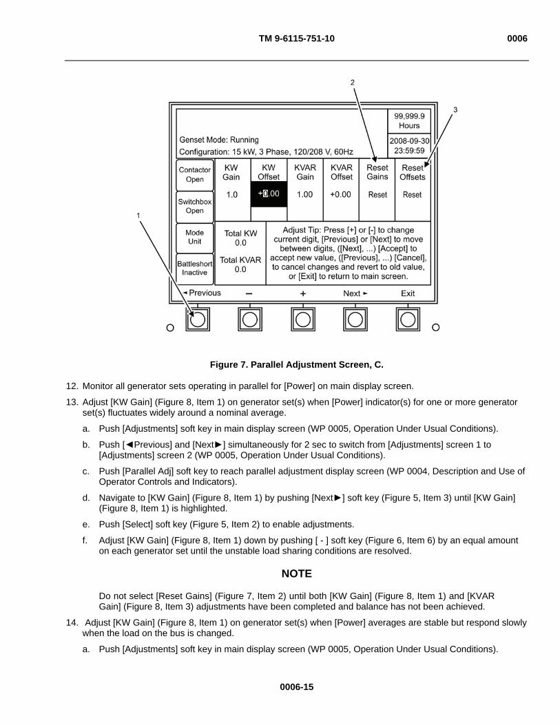
TM 9-6115-751-10 0006
Figure 7. Parallel Adjustment Screen, C.
12. Monitor all generator sets operating in parallel for [Power] on main display screen.
13. Adjust [KW Gain] (Figure 8, Item 1) on generator set(s) when [Power] indicator(s) for one or more generator set(s) fluctuates widely around a nominal average.
a. Push [Adjustments] soft key in main display screen (WP 0005, Operation Under Usual Conditions).
b. Push [ Previous] and [Next ] simultaneously for 2 sec to switch from [Adjustments] screen 1 to [Adjustments] screen 2 (WP 0005, Operation Under Usual Conditions).
c. Push [Parallel Adj] soft key to reach parallel adjustment display screen (WP 0004, Description and Use of Operator Controls and Indicators).
d. Navigate to [KW Gain] (Figure 8, Item 1) by pushing [Next ] soft key (Figure 5, Item 3) until [KW Gain] (Figure 8, Item 1) is highlighted.
e. Push [Select] soft key (Figure 5, Item 2) to enable adjustments.
f. Adjust [KW Gain] (Figure 8, Item 1) down by pushing [ - ] soft key (Figure 6, Item 6) by an equal amount on each generator set until the unstable load sharing conditions are resolved.
NOTE
Do not select [Reset Gains] (Figure 7, Item 2) until both [KW Gain] (Figure 8, Item 1) and [KVAR Gain] (Figure 8, Item 3) adjustments have been completed and balance has not been achieved.
14. Adjust [KW Gain] (Figure 8, Item 1) on generator set(s) when [Power] averages are stable but respond slowly when the load on the bus is changed.
a. Push [Adjustments] soft key in main display screen (WP 0005, Operation Under Usual Conditions).
0006-15
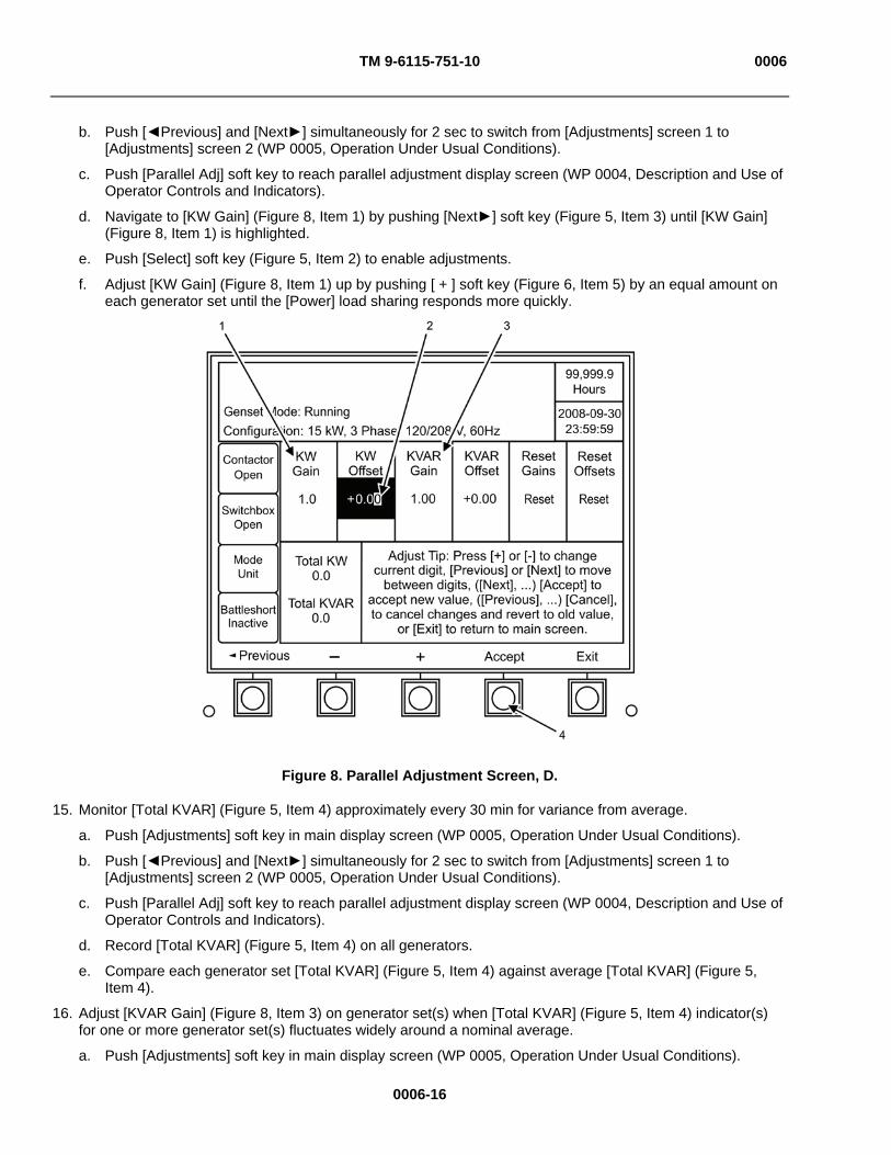
TM 9-6115-751-10 0006
b. Push [ Previous] and [Next ] simultaneously for 2 sec to switch from [Adjustments] screen 1 to [Adjustments] screen 2 (WP 0005, Operation Under Usual Conditions).
c. Push [Parallel Adj] soft key to reach parallel adjustment display screen (WP 0004, Description and Use of Operator Controls and Indicators).
d. Navigate to [KW Gain] (Figure 8, Item 1) by pushing [Next ] soft key (Figure 5, Item 3) until [KW Gain] (Figure 8, Item 1) is highlighted.
e. Push [Select] soft key (Figure 5, Item 2) to enable adjustments.
f. Adjust [KW Gain] (Figure 8, Item 1) up by pushing [ + ] soft key (Figure 6, Item 5) by an equal amount on each generator set until the [Power] load sharing responds more quickly.
Figure 8. Parallel Adjustment Screen, D.
15. Monitor [Total KVAR] (Figure 5, Item 4) approximately every 30 min for variance from average.
a. Push [Adjustments] soft key in main display screen (WP 0005, Operation Under Usual Conditions).
b. Push [ Previous] and [Next ] simultaneously for 2 sec to switch from [Adjustments] screen 1 to [Adjustments] screen 2 (WP 0005, Operation Under Usual Conditions).
c. Push [Parallel Adj] soft key to reach parallel adjustment display screen (WP 0004, Description and Use of Operator Controls and Indicators).
d. Record [Total KVAR] (Figure 5, Item 4) on all generators.
e. Compare each generator set [Total KVAR] (Figure 5, Item 4) against average [Total KVAR] (Figure 5, Item 4).
16. Adjust [KVAR Gain] (Figure 8, Item 3) on generator set(s) when [Total KVAR] (Figure 5, Item 4) indicator(s) for one or more generator set(s) fluctuates widely around a nominal average.
a. Push [Adjustments] soft key in main display screen (WP 0005, Operation Under Usual Conditions).
0006-16

TM 9-6115-751-10 0006
b. Push [ Previous] and [Next ] simultaneously for 2 sec to switch from [Adjustments] screen 1 to [Adjustments] screen 2 (WP 0005, Operation Under Usual Conditions).
c. Push [Parallel Adj] soft key to reach parallel adjustment display screen (WP 0004, Description and Use of Operator Controls and Indicators).
d. Navigate to [KVAR Gain] (Figure 8, Item 3) by pushing [Next ] soft key (Figure 5, Item 3) until [KVAR Gain] (Figure 8, Item 3) is highlighted.
e. Push [Select] soft key (Figure 5, Item 2) to enable adjustments.
f. Adjust [KVAR Gain] (Figure 8, Item 3) down by pushing [ - ] soft key (Figure 6, Item 6) by an equal amount on each generator set until the unstable load sharing conditions are resolved.
17. Adjust [KVAR Gain] (Figure 8, Item 3) on generator set(s) when [Total KVAR] (Figure 5, Item 4) averages are stable but respond slowly when the load on the bus is changed.
a. Push [Adjustments] soft key in main display screen (WP 0005, Operation Under Usual Conditions).
b. Push [ Previous] and [Next ] simultaneously for 2 sec to switch from [Adjustments] screen 1 to [Adjustments] screen 2 (WP 0005, Operation Under Usual Conditions).
c. Push [Parallel Adj] soft key to reach parallel adjustment display screen (WP 0004, Description and Use of Operator Controls and Indicators).
d. Navigate to [KVAR Gain] (Figure 8, Item 3) by pushing [Next ] soft key (Figure 5, Item 3) until [KVAR Gain] (Figure 8, Item 3) is highlighted.
e. Push [Select] soft key (Figure 5, Item 2) to enable adjustments.
f. Adjust [KVAR Gain] (Figure 8, Item 3) up by pushing [ + ] soft key (Figure 6, Item 5) by an equal amount on each generator set until the [Total KVAR] (Figure 5, Item 4) load sharing responds more quickly.
Figure 9. Parallel Adjustment Screen, E.
0006-17
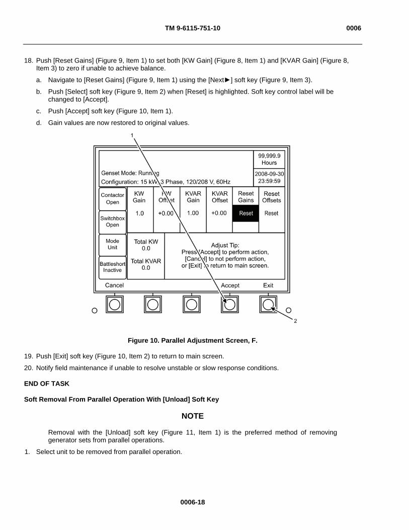
TM 9-6115-751-10 0006
18. Push [Reset Gains] (Figure 9, Item 1) to set both [KW Gain] (Figure 8, Item 1) and [KVAR Gain] (Figure 8, Item 3) to zero if unable to achieve balance.
a. Navigate to [Reset Gains] (Figure 9, Item 1) using the [Next ] soft key (Figure 9, Item 3).
b. Push [Select] soft key (Figure 9, Item 2) when [Reset] is highlighted. Soft key control label will be changed to [Accept].
c. Push [Accept] soft key (Figure 10, Item 1).
d. Gain values are now restored to original values.
Figure 10. Parallel Adjustment Screen, F.
19. Push [Exit] soft key (Figure 10, Item 2) to return to main screen.
20. Notify field maintenance if unable to resolve unstable or slow response conditions.
END OF TASK
Soft Removal From Parallel Operation With [Unload] Soft Key
NOTE
Removal with the [Unload] soft key (Figure 11, Item 1) is the preferred method of removing generator sets from parallel operations.
1. Select unit to be removed from parallel operation.
0006-18

TM 9-6115-751-10 0006
Figure 11. Soft Unload Key.
CAUTION
Ensure generator set(s) remaining on-line have sufficient capacity to carry the load required. Failure to comply will cause damage to equipment.
2. Select and push [Unload] soft key (Figure 11, Item 1).
NOTE
The DCS will automatically ramp down the load and open the output contactor to exit paralleling when the load has transferred.
3. Monitor main display screen. Mode will change to [Unit] when DCS has exited paralleling mode and transferred load to remaining generator(s).
4. Shut down generator set (WP 0005, Operation Under Usual Conditions) if required.
END OF TASK
0006-19

TM 9-6115-751-10 0006
Removal From Parallel Operation With UNIT PARALLEL Switch
NOTE
Removal with the [Unload] soft key (Figure 11, Item 1) is the preferred method of removing generator sets from parallel operations. Removal with the UNIT PARALLEL switch (Figure 12, Item 3) is not normally recommended.
Figure 12. DCS Panel, Remove From Parallel.
1. Switch to [UNIT] mode on first unit to be removed from parallel operation by pushing UNIT PARALLEL switch (Figure 12, Item 3).
2. Push AC CIRCUIT INTERRUPT switch (Figure 12, Item 1) to open contactor.
3. Shut down generator set (WP 0005, Operation Under Usual Conditions).
4. Switch to [UNIT] mode on next unit to be removed from parallel operation by pushing UNIT PARALLEL switch (Figure 12, Item 3).
5. Push AC CIRCUIT INTERRUPT switch (Figure 12, Item 1) to open contactor.
6. Shut down generator set (WP 0005, Operation Under Usual Conditions).
7. Repeat steps 1 through 3 for all remaining generator sets operating in parallel.
8. Remove paralleling cables from PARALLEL receptacle (Figure 12, Item 2) on all generator sets.
9. Store paralleling cables in generator set storage box located in right-side door.
10. Remove switch box contactor cable(s) (Figure 3, Item 3) from SWITCH BOX CONTROL RECEPTACLE (Figure 3, Item 1) if used.
END OF TASK
END OF WORK PACKAGE
0006-20

TM 9-6115-751-10 0007
0007-1
OPERATOR MAINTENANCE
AMMPS 15KW GENERATOR SET
OPERATION UNDER UNUSUAL CONDITIONS
INITIAL SETUP:
Test Equipment
Not Applicable
Tools and Special Tools
Not Applicable
Materials/Parts
Rags, wiping (WP 0021, Expendable and Durable Items List, Item 9)
Personnel Required
Operator (1)
References
FM 3-11.5
References
FM 3-3
FM 3-4
FM 3-5
FM 31-70
WP 0005, Operation Under Usual Conditions
WP 0010, Troubleshooting Procedures
WP 0014, Service Air Cleaner
WP 0016, Service Fuel System
Equipment Conditions
Not Applicable
OPERATION UNDER UNUSUAL CONDITIONS
WARNING
Exhaust discharge contains deadly gases, including carbon monoxide. Exhaust gases are most dangerous in places with poor ventilation. Do not operate generator set in an enclosed area unless exhaust discharge is properly vented. Failure to comply may cause injury or death to personnel.
High voltage is produced when generator set is in operation. Never attempt to start the generator set unless it is properly grounded. Do not ground yourself in standing water. Never attempt to connect or disconnect load cables while the generator set is running. Failure to comply may cause injury or death to personnel.
DC voltages are present at generator set electrical components even with generator set shut down. Avoid shorting any positive with ground/negative. Do not ground yourself in standing water. Failure to comply may cause injury or death to personnel and damage to equipment.
Generator set must be completely shut down prior to washing. Electrocution is possible. Failure to comply may cause injury or death to personnel.
TM 9-6115-751-10 0007
0007-2
WARNING
Do not start generator set until all internal components are completely dry. Electrocution is possible. Failure to comply may cause injury or death to personnel.
When operating, generator set engine has hot metal surfaces that will burn flesh on contact. Shut down generator set and allow engine to cool before checks, services, and maintenance. Wear gloves and additional protective clothing as required. Failure to comply may cause injury or death to personnel.
Operation in Extreme Cold -25°F (-31°C)
NOTE The generator set operates in ambient temperatures as low as -25°F (-31°C) without special winterization equipment. To ensure satisfactory operation under extremely cold weather, the following steps must be taken. For additional general information on cold weather operations, refer to FM 31-70, Basic Cold Weather Manual.
1. Provide a ventilated shelter for generator set, if possible. 2. Ensure generator set and surrounding area remain as free of ice and snow as possible.
WARNING
In extremely cold weather, skin can stick to metal. Avoid contacting metal items with bare skin in extremely cold weather. Failure to comply may cause injury or death to personnel.
3. Ensure fuel tank is kept full to protect against moisture, condensation, and accumulation of water.
4. Ensure that proper grade fuel is used (WP 0016, Service Fuel System).
5. Ensure batteries remain free from corrosion and in a well-charged condition.
END OF TASK
Operation in Extreme Heat Above 120°F (49°C)
1. Check vents and radiator air passages frequently for obstructions.
2. Check coolant temperature indicator frequently for indication of overheating.
3. Allow sufficient space for fuel expansion when filling fuel tank.
4. Ensure generator set remains clean and free of dirt.
5. Remove obstructions from generator intake and outlet screens.
6. Remove dirt and debris from external surface of engine when generator set is not operating.
END OF TASK
Operation in Dusty or Sandy Areas
1. Provide a ventilated shelter for generator set, if possible.
2. Use available natural barriers to shield the generator set from blowing dust or sand.
TM 9-6115-751-10 0007
0007-3
CAUTION
While wetting dusty/sandy areas, protect generator set from water and mud splash. Failure to comply will cause damage to equipment.
3. Wet dusty and sandy surface areas around generator set frequently if water is available.
4. Prevent entry of dust and sand into housing assembly by keeping all access doors closed as much as possible.
5. Wipe dust and sand frequently from the generator set external surfaces and components.
6. Wash exterior surfaces frequently with a damp wiping rag when generator set is not operating and is completely shut down.
7. Service engine air cleaner assembly (WP 0014, Service Air Cleaner) frequently to compensate for intake of additional dust or sand.
8. Drain sediment frequently from fuel filter/water separator.
CAUTION
When servicing fuel tank, prevent dust or sand from entering. Failure to comply will cause damage to equipment.
9. Request field maintenance change engine oil and oil filter frequently.
10. Store oil and fuel in dust-free containers.
11. Ensure that generator set ground connections are free of dust and sand and that connections are tight before starting the generator set.
END OF TASK
Operation in Rainy or Humid Conditions
1. Provide a ventilated shelter for generator set, if possible.
CAUTION
Failure to remove canvas or waterproof material before operating generator set may result in damage to equipment.
2. Cover generator set with canvas or other waterproof material when it is not being operated.
3. Provide adequate drainage to prevent water from accumulating on operation site.
4. Prevent water from entering the housing assembly when operating in rain or high humidity by keeping all generator set access doors closed.
5. Drain water frequently from fuel filter/water separator.
6. Check wiring connections for corrosion, and check wire insulation for signs of deterioration. Contact field maintenance if any of these conditions exist.
END OF TASK
Operation in Salt Water Areas
1. Provide a ventilated shelter for the generator set, if possible.
2. Locate generator set so that radiator faces into prevailing winds.

TM 9-6115-751-10 0007
0007-4
3. Use natural barriers or, if possible, construct a barrier to protect generator set from salt water.
CAUTION
Failure to remove canvas or waterproof material before operating generator set may result in damage to equipment.
4. Cover generator set with canvas or other waterproof material when it is not being operated.
5. Prevent water from entering the housing assembly when operating in salt-water areas by keeping all generator set access doors closed.
CAUTION
Protect generator set from water and mud splash while wiping. Failure to comply will cause damage to equipment.
6. Wash exterior surfaces frequently with a damp wiping rag when generator set is not operating and is completely shut down.
7. Check wiring connections for corrosion and wire insulation for signs of deterioration daily. Contact field maintenance if any of these conditions exist.
END OF TASK
Operation in High Altitudes
The generator set will operate at elevations up to 4000 ft (1219.1 m) above sea level without special adjustment or reduction in load. At elevations greater than 4000 ft (1219.1 m) above sea level, the kilowatt rating is reduced approximately 3.5% for each additional 1000 ft (304.8 m).
END OF TASK

TM 9-6115-751-10 0007
0007-5
Operation Using BATTLESHORT Switch
Figure 1. DCS Panel.
1. Engage BATTLESHORT switch (Figure 1, Item 1) only when ordered by higher command.
CAUTION
Continued operation using the BATTLESHORT switch (Figure 1, Item 1) may result in damage to equipment. Stop using BATTLESHORT immediately when ordered by higher command. Failure to comply may cause damage to equipment.
NOTE
BATTLESHORT switch (Figure 1, Item 1) must be in OFF position to start generator set.
If any emergency situation requires continued operation of the generator set, the BATTLESHORT switch (Figure 1, Item 1) is used to override all the safety devices except the short circuit devices and the emergency stop function.
2. Start generator set if set is not operating (WP 0005, Operation Under Usual Conditions).
3. Lift cover on BATTLESHORT switch (Figure 1, Item 1), and place switch in ON position.
4. Lift cover on BATTLESHORT switch (Figure 1, Item 1), and place switch in OFF position when BATTLESHORT conditions no longer exist.
END OF TASK
TM 9-6115-751-10 0007
0007-6
Operation While in Contaminated Areas
The generator set is capable of being operated by personnel wearing Chemical, Biological, Radiological, and Nuclear (CBRN) protective clothing without special tools or supporting equipment. Refer to FM 3-5, NBC Decontamination for information on decontamination procedures. Specific procedures for the generator set are the following:
1. Control panel indicators sealing gasket, rubber sleeves, rope draw cords at output load terminal access ports, control panel door gaskets, access door gaskets, rubber tubing, belts within the engine compartment, coverings for electrical conduits, external water drain tubing, and retaining cords for slave receptacle covers will absorb and retain chemical agents. Replacement of these items is the recommended method of decontamination.
2. Lubricants, fuel, coolant, or battery fluids may be present on the external surfaces of the generator set or components due to leaks or normal operation. These fluids will absorb CBRN agents. The preferred method of decontamination is removal of these fluids using conventional decontamination methods IAW FM 3-5, NBC Decontamination.
3. Indicators should be decontaminated with warm, soapy water. Continued decontamination of external generator set surfaces with Super-Topical Bleach (STB)/Decontamination Solution number 2 (DS2) will degrade clear plastic indicator coverings to a point where reading indicators will become impossible. This problem will become more evident for soldiers wearing protective masks; therefore, the use of STB or DS2 decontamination in these areas should be minimized.
4. The recommended method of decontamination for external surfaces of the control panel is with warm, soapy water. External surfaces of the DCS panel assembly that are marked with painted or stamped lettering will not withstand repeated decontamination with STB or DS2 without degradation of the lettering.
5. Replacement of the following items, if available, is the preferred method of decontamination. The areas will entrap contaminants, making efficient decontamination extremely difficult. Conventional methods of decontamination, if used, must stress the importance of thoroughness and the probability of some degree of continuing contact and vapor hazard.
a. Exposed heads of screws.
b. Areas adjacent to and behind exposed wiring conduits.
c. Hinged areas or access doors.
d. Retaining chains for external receptacle covers.
e. Areas around the tie-down/lifting rings, crevices around access doors, external screens covering ventilation areas, the external oil drain valve, and areas adjacent to the external fuel drain valve.
f. Areas behind knobs and switches on the control panel, externally mounted equipment specification data plates, external receptacle covers, access doors, access door locking mechanisms, recessed wells for access door handles, fuel cap, load terminal board, slave receptacles, and frequency adjustment controls.
6. The generator set should be operated with all access doors closed to reduce the effects of contamination if in a CBRN-contaminated environment.
7. The use of overhead shelters or chemical protective covers is recommended as an additional means of protection against contamination IAW FM 3-5, NBC Decontamination. If using covers, care should be taken to provide adequate space for air flow and exhaust.
8. Additional CBRN information can be found at FM 3-3, Chemical and Biological Contamination Avoidance; and, FM 3-4, NBC Protection. Other services use applicable publications for CBRN in addition to FM 3-11.5, Multiservice Tactics, Techniques, and Procedures for Chemical, Biological, Radiological, and Nuclear Decontamination.
END OF TASK
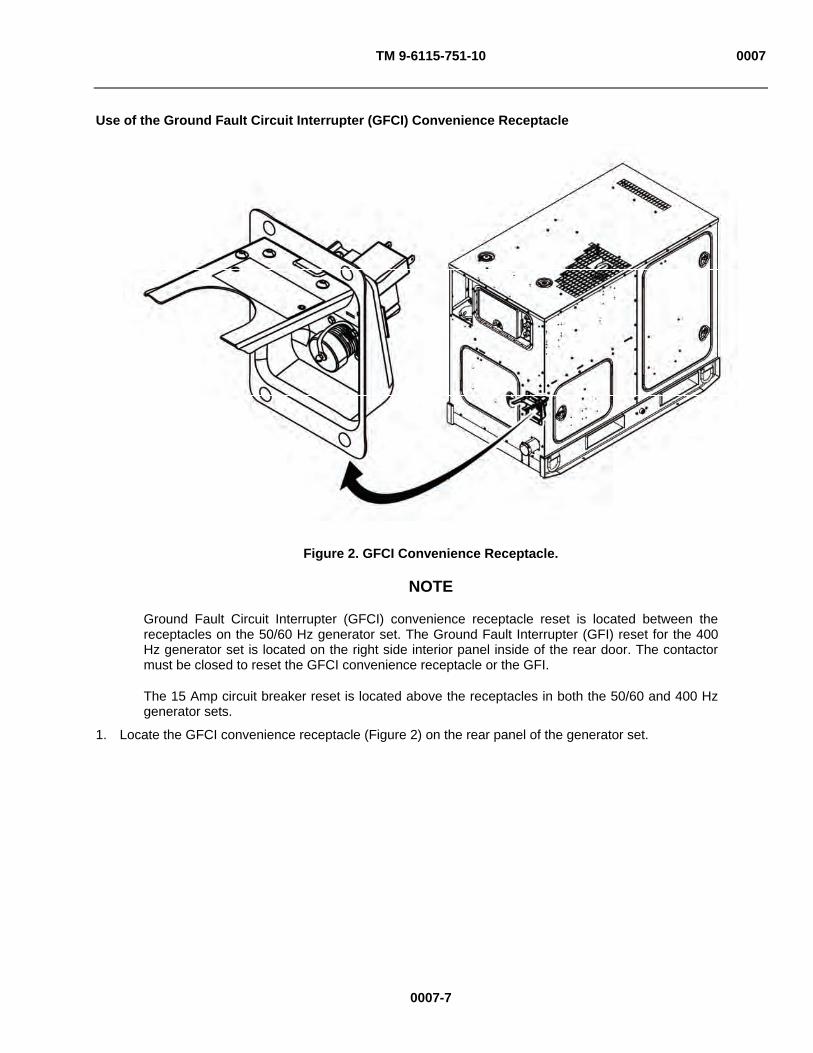
TM 9-6115-751-10 0007
0007-7
Use of the Ground Fault Circuit Interrupter (GFCI) Convenience Receptacle
Figure 2. GFCI Convenience Receptacle.
NOTE
Ground Fault Circuit Interrupter (GFCI) convenience receptacle reset is located between the receptacles on the 50/60 Hz generator set. The Ground Fault Interrupter (GFI) reset for the 400 Hz generator set is located on the right side interior panel inside of the rear door. The contactor must be closed to reset the GFCI convenience receptacle or the GFI.
The 15 Amp circuit breaker reset is located above the receptacles in both the 50/60 and 400 Hz generator sets.
1. Locate the GFCI convenience receptacle (Figure 2) on the rear panel of the generator set.

TM 9-6115-751-10 0007
0007-8
WARNING
Power is available to the convenience receptacle only when the main contactor is closed. Avoid accidental contact. Electrocution is possible. Failure to comply may cause injury or death to personnel.
Ensure the frequency of any device powered by the GFCI convenience receptacle matches the frequency of the generator set. Failure to comply can cause serious injury or death to personnel.
CAUTION
The 400 Hz generator set GFCI convenience receptacle may only be used on resistive load devices drawing less than 15 Amps. Do not use the 400 Hz convenience receptacle for power tools, computers, or computer-like devices. The 50/60 Hz generator set GFCI convenience receptacle may be used for any device drawing less than 15 Amps. Failure to comply will cause damage to equipment.
The maximum power rating for the GFCI convenience receptacle is 15 Amps. Avoid continuous operation above 15 Amps. Failure to comply may cause damage to equipment.
2. Start the generator set if it is not operating (WP 0005, Operation Under Usual Conditions).
3. Ensure load does not exceed the maximum rating.
4. Reset the GFCI/GFI.
5. Plug appropriate connector into convenience receptacle.
END OF TASK
END OF WORK PACKAGE
XXXXXXXXXXXXXXX TM 9-6115-751-10 0008
X
0008-1
XXXXXXXXXXXXXXX
OPERATOR MAINTENANCE
AMMPS 15KW GENERATOR SET
EMERGENCY
INITIAL SETUP:
Test Equipment
Not Applicable
Tools and Special Tools
Not Applicable
Materials/Parts
Not Applicable
Personnel Required
Operator (1)
References
WP 0005, Operation Under Usual Conditions
WP 0010, Troubleshooting Procedures
Equipment Conditions
Not Applicable
XXXXXXXXXXXXX
NATO SLAVE RECEPTACLE START OPERATION
WARNING
High voltage is produced when the generator set is in operation. Never attempt to start the generator set unless it is properly grounded. Do not ground yourself in standing water. Never attempt to connect or disconnect load cables while the generator set is operating. Failure to comply can cause injury or death to personnel.
1. Ensure equipment conditions are met in order presented in initial setup.
2. Locate NATO slave receptacle (Figure 1, Item 2) on front-side of generator set.

XXXXXXXXXXXXXXX TM 9-6115-751-10 0008
0008-2
XXXXXXXXXXXXXXX
Figure 1. NATO Slave Receptacle.
WARNING
NATO slave receptacle is electrically live at all times and is not protected by a fuse. Disconnecting main DC circuit breaker does not ensure the circuit is dead. This circuit is only dead when the batteries are fully disconnected. Disconnect both batteries before performing maintenance on the slave receptacle. Failure to comply may cause injury or death to personnel.
3. Ensure 24-VDC power source system is fully charged.
4. Remove protective cover (Figure 1, Item 1) from NATO slave receptacle (Figure 1, Item 2). 5. Connect one end of NATO slave cable to fully-charged 24-VDC system and other end to discharged
generator set NATO slave receptacle (Figure 1, Item 2).
NOTE
The NATO slave receptacle (Figure 1, Item 2) can be used to start generator set when batteries are discharged.
6. Start fully-charged 24-VDC system.
7. Start generator set (WP 0005, Operation Under Usual Conditions).
8. Remove NATO slave cable after generator set starts.
END OF TASK
X X X X X X X X X X X XXX

XXXXXXXXXXXXXXX TM 9-6115-751-10 0008
X
0008-3
XXXXXXXXXXXXXXX
XXXXXXXXXXXXX
EMERGENCY STOPPING
Figure 2. DCS Panel.
1. Push EMERGENCY STOP (Figure 2, Item 1) if operating parameters exceed those permitted in Table 3, WP 0005, Operation Under Usual Conditions.
2. Resolve problem using troubleshooting procedures (WP 0010, Troubleshooting Procedures).
3. Push FAULT RESET (Figure 2, Item 2) switch to clear fault from DCS.
NOTE
To restart the generator set, the following steps must be completed.
4. Pull out EMERGENCY STOP (Figure 2, Item 1) switch.
5. Turn engine control switch (Figure 2, Item 3) to OFF.
6. Restart generator set (WP 0005, Operation Under Usual Conditions).
END OF TASK
XXXXXXXXXXXXXXX TM 9-6115-751-10 0008
OPERATION USING BATTLESHORT SWITCH
1. Engage BATTLESHORT switch (Figure 2, Item 4) only when ordered by higher command.
0008-4
XXXXXXXXXXXXXXX
CAUTION
Continued operation using the BATTLESHORT switch (Figure 2, Item 4) may result in damage to equipment. Stop using BATTLESHORT switch (Figure 2, Item 4) immediately when ordered by higher command. Failure to comply may cause damage to equipment.
NOTE
BATTLESHORT switch (Figure 2, Item 4) must be in OFF position to start generator set.
If any emergency situation requires continued operation of the generator set, the BATTLESHORT switch (Figure 2, Item 4) is used to override all the safety devices except the short circuit devices and the emergency stop function.
2. Start generator set if set not operating (WP 0005, Operation Under Usual Conditions).
3. Lift cover on BATTLESHORT switch (Figure 2, Item 4) and place switch in ON position.
4. Lift cover on BATTLESHORT switch (Figure 2, Item 4) and place switch in OFF position when BATTLESHORT conditions no longer exist.
END OF TASK
END OF WORK PACKAGE
X X X X X X X X X X X XXX

TM 9-6115-751-10
CHAPTER 3
TROUBLESHOOTING PROCEDURES FOR
AMMPS 15KW GENERATOR SET

TM 9-6115-751-10
CHAPTER 3
TROUBLESHOOTING PROCEDURES
WORK PACKAGE INDEX
Title WP Sequence No.
TROUBLESHOOTING INDEX............................................................................................................................. 0009
TROUBLESHOOTING PROCEDURES .............................................................................................................. 0010
DCS FAULT & WARNING CODES AND DESCRIPTIONS................................................................................. 0011
TM 9-6115-751-10 0009
0009-1
OPERATOR MAINTENANCE
AMMPS 15KW GENERATOR SET
TROUBLESHOOTING INDEX
GENERAL TROUBLESHOOTING INFORMATION
Operator troubleshooting procedures are designed to isolate and correct AMMPS faults and warnings so that electrical power is provided to end-users with the least possible service interruption. Troubleshooting techniques apply to all AMMPS components as indicated.
Troubleshooting procedures list the symptoms, malfunctions, and corrective actions required to correct system faults and warnings. Perform all steps in the order they appear in the WP. Troubleshooting procedures are listed according to symptom, followed by the malfunction, and then any corrective action(s). All necessary references to procedures/instructions can be found within the Troubleshooting WP (WP 0010, Troubleshooting Procedures).
The DCS constantly monitors the engine sensors for abnormal conditions, such as low oil pressure and high coolant temperature. If any of these conditions occur, the DCS panel will display a message indicating a fault or warning code. The system will shut down if a fault is indicated. If a warning is indicated but not addressed, it will frequently become a fault. If a malfunction or failure occurs during operation or performance check, perform troubleshooting IAW the Malfunction/Symptom Index and any displayed fault or warning codes (WP 0011, DCS Fault & Warning Codes and Descriptions).
Do not begin a task until you understand the task.
MALFUNCTION/SYMPTOM INDEX
The malfunction/symptom index is a quick reference for locating troubleshooting procedures. Troubleshooting procedures are arranged based upon the location of the malfunction (i.e., engine, alternator, or controls) and the presence of a DCS code.
DCS Fault and Warning Codes
Refer to WP 0011, DCS Fault & Warning Codes and Descriptions, for a complete list of DCS fault and warning codes.
Indications from Manual Troubleshooting Techniques
Field maintenance is responsible for performing manual troubleshooting techniques, including continuity tests and voltage checks, maintenance actions that require the use of tools, and DCS function activities other than routine operator adjustments.
After Corrective Action
After the corrective action is completed, the equipment must be tested to verify that a fault or warning has been corrected. Locate the malfunction in the troubleshooting procedures and perform the test or inspection. If the correct response is not obtained, continue to troubleshoot all suspected malfunctions and perform corresponding corrective actions until the equipment is operational or is replaced with operational equipment.
Specific Troubleshooting Procedures
This TM cannot list all malfunctions that may occur or all tests or inspections and corrective actions. If a malfunction is not listed or is not corrected by the listed corrective action, notify field maintenance.
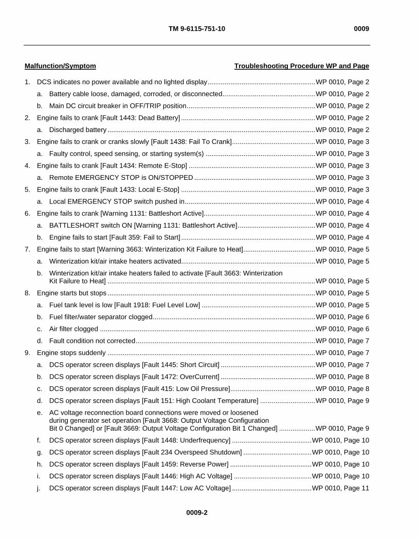
TM 9-6115-751-10 0009
0009-2
Malfunction/Symptom Troubleshooting Procedure WP and Page
1. DCS indicates no power available and no lighted display.........................................................WP 0010, Page 2
a. Battery cable loose, damaged, corroded, or disconnected.................................................WP 0010, Page 2
b. Main DC circuit breaker in OFF/TRIP position....................................................................WP 0010, Page 2
2. Engine fails to crank [Fault 1443: Dead Battery] .......................................................................WP 0010, Page 2
a. Discharged battery ..............................................................................................................WP 0010, Page 2
3. Engine fails to crank or cranks slowly [Fault 1438: Fail To Crank]............................................WP 0010, Page 3
a. Faulty control, speed sensing, or starting system(s) ..........................................................WP 0010, Page 3
4. Engine fails to crank [Fault 1434: Remote E-Stop] ...................................................................WP 0010, Page 3
a. Remote EMERGENCY STOP is ON/STOPPED ................................................................WP 0010, Page 3
5. Engine fails to crank [Fault 1433: Local E-Stop] .......................................................................WP 0010, Page 3
a. Local EMERGENCY STOP switch pushed in.....................................................................WP 0010, Page 4
6. Engine fails to crank [Warning 1131: Battleshort Active]...........................................................WP 0010, Page 4
a. BATTLESHORT switch ON [Warning 1131: Battleshort Active].........................................WP 0010, Page 4
b. Engine fails to start [Fault 359: Fail to Start] .......................................................................WP 0010, Page 4
7. Engine fails to start [Warning 3663: Winterization Kit Failure to Heat]......................................WP 0010, Page 5
a. Winterization kit/air intake heaters activated.......................................................................WP 0010, Page 5
b. Winterization kit/air intake heaters failed to activate [Fault 3663: Winterization Kit Failure to Heat] ..............................................................................................................WP 0010, Page 5
8. Engine starts but stops ..............................................................................................................WP 0010, Page 5
a. Fuel tank level is low [Fault 1918: Fuel Level Low] ............................................................WP 0010, Page 5
b. Fuel filter/water separator clogged......................................................................................WP 0010, Page 6
c. Air filter clogged ..................................................................................................................WP 0010, Page 6
d. Fault condition not corrected...............................................................................................WP 0010, Page 7
9. Engine stops suddenly ..............................................................................................................WP 0010, Page 7
a. DCS operator screen displays [Fault 1445: Short Circuit] ..................................................WP 0010, Page 7
b. DCS operator screen displays [Fault 1472: OverCurrent] ..................................................WP 0010, Page 8
c. DCS operator screen displays [Fault 415: Low Oil Pressure].............................................WP 0010, Page 8
d. DCS operator screen displays [Fault 151: High Coolant Temperature] .............................WP 0010, Page 9
e. AC voltage reconnection board connections were moved or loosened during generator set operation [Fault 3668: Output Voltage Configuration Bit 0 Changed] or [Fault 3669: Output Voltage Configuration Bit 1 Changed] ...................WP 0010, Page 9
f. DCS operator screen displays [Fault 1448: Underfrequency] ..........................................WP 0010, Page 10
g. DCS operator screen displays [Fault 234 Overspeed Shutdown] ....................................WP 0010, Page 10
h. DCS operator screen displays [Fault 1459: Reverse Power] ...........................................WP 0010, Page 10
i. DCS operator screen displays [Fault 1446: High AC Voltage] .........................................WP 0010, Page 10
j. DCS operator screen displays [Fault 1447: Low AC Voltage] ..........................................WP 0010, Page 11

TM 9-6115-751-10 0009
0009-3
Malfunction/Symptom Troubleshooting Procedure WP and Page
10. AC voltage fluctuation..............................................................................................................WP 0010, Page 11
a. Erratic change in voltage shown on [GENSET VOLTAGE] indicator ...............................WP 0010, Page 11
11. AC frequency fluctuation .........................................................................................................WP 0010, Page 11
a. Erratic change in frequency shown on DCS [FREQ] indicator .........................................WP 0010, Page 11
12. DCS operator screen displays [Warning 143: Pre-Low Oil Pressure].....................................WP 0010, Page 12
a. Engine oil level below normal ...........................................................................................WP 0010, Page 12
b. Improper grade of oil for conditions ..................................................................................WP 0010, Page 12
13. DCS operator screen displays [Warning 146: Pre-High Coolant Temperature]......................WP 0010, Page 12
a. Coolant temperature lower than FAULT condition but higher than normal ......................WP 0010, Page 12
b. Obstructed ventilation and air flow paths ..........................................................................WP 0010, Page 13
14. DCS operator screen displays [Warning 1441: Low Fuel Level].............................................WP 0010, Page 13
a. Fuel level greater than [Fault] condition level of 2% but less than 4% .............................WP 0010, Page 13
b. Faulty fuel level sensor .....................................................................................................WP 0010, Page 14
15. DCS operator screen displays [Warning 2936: Fuel Level Sensor High] or [Warning 2937: Fuel Level Sensor Low] .................................................................................WP 0010, Page 14
a. Faulty fuel sensor ..............................................................................................................WP 0010, Page 14
16. DCS operator screen displays [Warning 441: Low Battery Voltage], [Warning 1442: Weak Battery], [Warning 3662: Battery Discharge], or [Warning 3663: Winterization Kit Failure to Heat] ...................................................................................................................WP 0010, Page 14
a. Battery cables loose, damaged, corroded, or disconnected.............................................WP 0010, Page 14
b. Faulty battery-charging alternator .....................................................................................WP 0010, Page 15
17. DCS operator screen displays [Warning 1444: KW Overload]................................................WP 0010, Page 15
a. Load placed on generator is more than the capacity of the generator .............................WP 0010, Page 15
18. DCS operator screen displays [Warning 1471: Overcurrent] ..................................................WP 0010, Page 15
a. Current above normal but not sufficient to create a FAULT condition..............................WP 0010, Page 15
19. DCS operator screen displays [Warning 1416: Fail To Shutdown] .........................................WP 0010, Page 16
a. Engine failed to shutdown after engine control switch was turned to OFF position .........WP 0010, Page 16
20. DCS operator screen displays [Warning 1449: Overfrequency] .............................................WP 0010, Page 16
a. Generator set was subjected to a single step large block load removal that was within the parameters of speed control but sufficient to create a [Warning 1449: Overfrequency] condition ..................................................................................................WP 0010, Page 16
21. DCS operator screen displays [Warning 3678: Genset Frequency Changed]........................WP 0010, Page 17
a. Frequency changed from parameters selected upon generator start-up or normal operation ...............................................................................................................WP 0010, Page 17
22. DCS operator screen displays [Warning 1417: Power Down Failure].....................................WP 0010, Page 17
a. Processor fault [Warning 1417: Power Down Failure] message appears for longer than 10 min ............................................................................................................WP 0010, Page 17

TM 9-6115-751-10 0009
0009-4
Malfunction/Symptom Troubleshooting Procedure WP and Page
23. DCS operator screen displays [Warning 1457: Fail To Synchronize] .....................................WP 0010, Page 17
a. Generator set paralleling parameters improperly selected or greater than allowed by synchronizing detectors ..................................................................................WP 0010, Page 17
24. DCS operator screen displays [Warning 3658: Switch Box Fail To Close] .............................WP 0010, Page 18
a. Paralleling operations are being conducted without a switch box ....................................WP 0010, Page 18
b. Generator set paralleling parameters improperly selected or greater than allowed by synchronizing detectors ..................................................................................WP 0010, Page 18
25. Engine exhaust smoking .........................................................................................................WP 0010, Page 18
a. Engine emits white exhaust smoke...................................................................................WP 0010, Page 18
b. Engine emits black exhaust smoke...................................................................................WP 0010, Page 19
c. Engine emits blue exhaust smoke due to oil in combustion chambers ............................WP 0010, Page 19
26. Engine starts but develops lower than rated speed ................................................................WP 0010, Page 20
a. Engine speed is low but not enough to create a fault or warning condition......................WP 0010, Page 20
27. Engine starts at speed but less than rated voltage .................................................................WP 0010, Page 20
a. Automatic voltage regulator system or component(s) subjected to fault condition................................................................................................WP 0010, Page 20
28. Power not available at GFCI CONVENIENCE RECEPTACLE...............................................WP 0010, Page 20
a. GFCI CONVENIENCE RECEPTACLE has been subjected to a ground fault condition.................................................................................................WP 0010, Page 20
END OF WORK PACKAGE

TM 9-6115-751-10 0010
0010-1
OPERATOR MAINTENANCE
AMMPS 15KW GENERATOR SET
TROUBLESHOOTING PROCEDURES
INITIAL SETUP:
Test Equipment
Not Applicable
Tools and Special Tools
Not Applicable
Materials/Parts
Not Applicable
Personnel Required
Operator (1)
References
WP 0011, DCS Fault & Warning Codes and Descriptions
References
WP 0013, PMCS
WP 0014, Service Air Cleaner
WP 0015, Service Cooling System
WP 0016, Service Fuel System
WP 0017, Service Engine Oil
Equipment Conditions
Engine control switch set to PRIME & RUN AUX FUEL or PRIME & RUN (WP 0005, Operation Under Usual Conditions)
TROUBLESHOOTING PROCEDURES
WARNING
Shut down generator sets before performing inspection of load cables. Failure to comply may cause injury or death to personnel.
When operating, generator set engine has hot metal surfaces that will burn flesh on contact. Shut down generator set and allow engine to cool before checks, services, and maintenance. Wear gloves and additional protective clothing as required. Failure to comply may cause injury or death to personnel.
Cooling system operates at high temperature and pressure. Contact with high-pressure steam and/or liquids can cause burns and scalding. Shut down generator set and allow system to cool before performing checks, services, and maintenance. Wear gloves, additional protective clothing, and goggles as required. Contact with high-pressure steam and/or liquids can cause burns and scalding. Failure to comply may cause injury or death to personnel.
NOTE
Always perform PMCS prior to beginning any troubleshooting procedure (WP 0013, PMCS). Follow all procedures for starting the generator set (WP 0005, Operation Under Usual Conditions).
Read the entire CORRECTIVE ACTION sequence before beginning steps to complete CORRECTIVE ACTION for a MALFUNCTION.
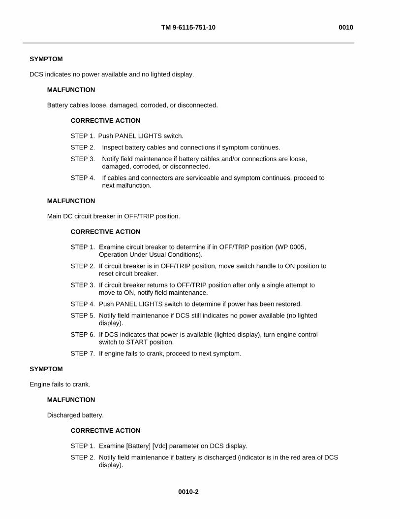
TM 9-6115-751-10 0010
0010-2
SYMPTOM
DCS indicates no power available and no lighted display.
MALFUNCTION
Battery cables loose, damaged, corroded, or disconnected.
CORRECTIVE ACTION
STEP 1. Push PANEL LIGHTS switch.
STEP 2. Inspect battery cables and connections if symptom continues.
STEP 3. Notify field maintenance if battery cables and/or connections are loose, damaged, corroded, or disconnected.
STEP 4. If cables and connectors are serviceable and symptom continues, proceed to next malfunction.
MALFUNCTION
Main DC circuit breaker in OFF/TRIP position.
CORRECTIVE ACTION
STEP 1. Examine circuit breaker to determine if in OFF/TRIP position (WP 0005, Operation Under Usual Conditions).
STEP 2. If circuit breaker is in OFF/TRIP position, move switch handle to ON position to reset circuit breaker.
STEP 3. If circuit breaker returns to OFF/TRIP position after only a single attempt to move to ON, notify field maintenance.
STEP 4. Push PANEL LIGHTS switch to determine if power has been restored.
STEP 5. Notify field maintenance if DCS still indicates no power available (no lighted display).
STEP 6. If DCS indicates that power is available (lighted display), turn engine control switch to START position.
STEP 7. If engine fails to crank, proceed to next symptom.
SYMPTOM
Engine fails to crank.
MALFUNCTION
Discharged battery.
CORRECTIVE ACTION
STEP 1. Examine [Battery] [Vdc] parameter on DCS display.
STEP 2. Notify field maintenance if battery is discharged (indicator is in the red area of DCS display).

TM 9-6115-751-10 0010
0010-3
STEP 3. If battery indicates charged (indicator is in the green area of DCS display), push FAULT RESET switch to clear fault on DCS.
STEP 4. Turn engine control switch to START position.
STEP 5. Attempt to start generator set using NATO slave receptacle (WP 0008, Emergency).
STEP 6. Notify field maintenance if battery indicator remains in the red area on DCS display.
SYMPTOM
Engine fails to crank or cranks slowly [Fault 1438: Fail To Crank].
MALFUNCTION
Faulty control, speed sensing, or starting system(s).
CORRECTIVE ACTION
Notify field maintenance.
NOTE Symptom applies only if generator set is configured for remote operation. If generator set is not configured for remote operation, proceed to next symptom.
SYMPTOM
Engine fails to crank [Fault 1434: Remote E-Stop].
MALFUNCTION
Remote EMERGENCY STOP is ON/STOPPED.
CORRECTIVE ACTION
STEP 1. Determine cause if EMERGENCY STOP command was enabled intentionally.
STEP 2. Restore from cause, if possible (WP 0011, DCS Fault & Warning Codes and Descriptions).
STEP 3. Notify field maintenance if unable to restore from cause.
STEP 4. Disable remote EMERGENCY STOP.
STEP 5. Place PC cursor over EMERGENCY STOP command symbol and click mouse or press ENTER on keyboard.
STEP 6. If EMERGENCY STOP command was not enabled intentionally, complete the preceding STEP 4 and STEP 5, and then proceed to STEP 7.
STEP 7. Push FAULT RESET switch at DCS panel to clear [Fault 1433: Remote E-Stop].
STEP 8. Turn engine control switch to START.
STEP 9. If engine fails to crank, proceed to next symptom.
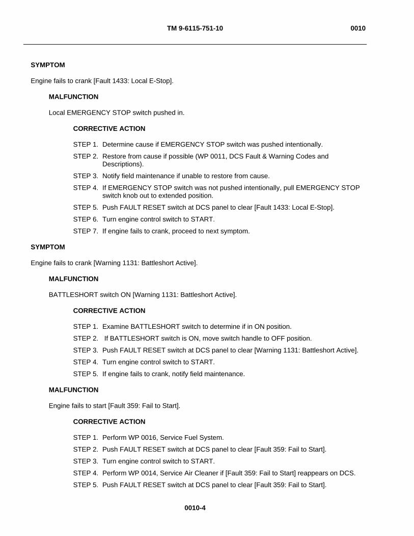
TM 9-6115-751-10 0010
0010-4
SYMPTOM
Engine fails to crank [Fault 1433: Local E-Stop].
MALFUNCTION
Local EMERGENCY STOP switch pushed in.
CORRECTIVE ACTION
STEP 1. Determine cause if EMERGENCY STOP switch was pushed intentionally.
STEP 2. Restore from cause if possible (WP 0011, DCS Fault & Warning Codes and Descriptions).
STEP 3. Notify field maintenance if unable to restore from cause.
STEP 4. If EMERGENCY STOP switch was not pushed intentionally, pull EMERGENCY STOP switch knob out to extended position.
STEP 5. Push FAULT RESET switch at DCS panel to clear [Fault 1433: Local E-Stop].
STEP 6. Turn engine control switch to START.
STEP 7. If engine fails to crank, proceed to next symptom.
SYMPTOM
Engine fails to crank [Warning 1131: Battleshort Active].
MALFUNCTION
BATTLESHORT switch ON [Warning 1131: Battleshort Active].
CORRECTIVE ACTION
STEP 1. Examine BATTLESHORT switch to determine if in ON position.
STEP 2. If BATTLESHORT switch is ON, move switch handle to OFF position.
STEP 3. Push FAULT RESET switch at DCS panel to clear [Warning 1131: Battleshort Active].
STEP 4. Turn engine control switch to START.
STEP 5. If engine fails to crank, notify field maintenance.
MALFUNCTION
Engine fails to start [Fault 359: Fail to Start].
CORRECTIVE ACTION
STEP 1. Perform WP 0016, Service Fuel System.
STEP 2. Push FAULT RESET switch at DCS panel to clear [Fault 359: Fail to Start].
STEP 3. Turn engine control switch to START.
STEP 4. Perform WP 0014, Service Air Cleaner if [Fault 359: Fail to Start] reappears on DCS.
STEP 5. Push FAULT RESET switch at DCS panel to clear [Fault 359: Fail to Start].

TM 9-6115-751-10 0010
0010-5
STEP 6. Turn engine control switch to START.
STEP 7. Notify field maintenance if [Fault 359: Fail to Start] reappears on DCS display.
SYMPTOM
Engine fails to start [Warning 3663: Winterization Kit Failure to Heat].
MALFUNCTION
Winterization kit/air intake heaters failed to activate [Fault 3663: Winterization Kit Failure to Heat].
NOTE
Air intake heaters report on DCS as [Glw Plg].
CORRECTIVE ACTION
STEP 1. Examine cold weather starting aid status on DCS display.
STEP 2. Turn engine control switch to PRIME & RUN or PRIME & RUN AUX FUEL position if fuel is being supplied from an auxiliary source.
STEP 3. Observe coolant temperature indicator on DCS display.
STEP 4. When coolant and ambient air temperature are below 45°F (7°C), [NOT READY TO CRANK] message will appear on DCS display.
STEP 5. Wait until [READY TO CRANK] message appears after the allotted time has passed, as indicated on the DCS display.
STEP 6. Turn engine control switch to START position.
STEP 7. If engine fails to start, notify field maintenance.
MALFUNCTION
Winterization kit/air intake heaters activated.
NOTE Air intake heaters report on DCS as [Glw Plg].
CORRECTIVE ACTION
STEP 1. Examine cold weather starting aid status on DCS display.
STEP 2. Turn engine control switch to PRIME & RUN or PRIME & RUN AUX FUEL position if fuel is being supplied from an auxiliary source.
STEP 3. Observe coolant temperature indicator on DCS display.
STEP 4. If coolant and ambient temperature are above 45°F (7°C) and cold start aids are activated, move main DC circuit breaker to OFF/TRIP position.
STEP 5. Notify field maintenance if starting aids activated prematurely.

TM 9-6115-751-10 0010
0010-6
SYMPTOM
Engine starts but stops.
MALFUNCTION
Fuel tank level is low [Fault 1918: Fuel Level Low].
CORRECTIVE ACTION
STEP 1. Examine fuel level indication on DCS display.
STEP 2. If fault status line indicates [Fault 1918: Fuel Level Low] or if fuel indicator is in the yellow or red area, refill fuel tank (WP 0016, Service Fuel System).
STEP 3. Examine fuel level visually if no level indication appears on DCS display (WP 0016, Service Fuel System).
STEP 4. If fuel is not visible, refill fuel tank (WP 0016, Service Fuel System).
STEP 5. Examine DCS fault status line for additional fault(s) that is/are displayed.
STEP 6. Restore from fault(s) if possible (WP 0011, DCS Fault & Warning Codes and Descriptions).
STEP 7. Notify field maintenance if unable to clear fault.
NOTE
FAULT RESET switch must be pushed to clear each fault code as it is displayed on the DCS display when more than one FAULT code has been presented.
STEP 8. Turn engine control switch to START position.
STEP 9. If engine starts but stops after START switch has been released, proceed to next malfunction.
MALFUNCTION
Fuel filter/water separator clogged.
CORRECTIVE ACTION
STEP 1. Service fuel filter/water separator (WP 0016, Service Fuel System).
STEP 2. Turn engine control switch to START position.
STEP 3. If engine starts but stops after START switch has been released, proceed to next malfunction.
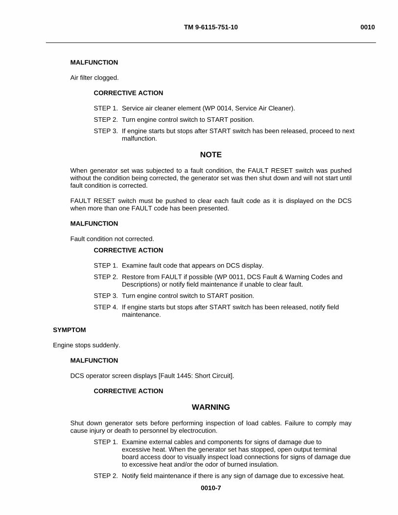
TM 9-6115-751-10 0010
0010-7
MALFUNCTION
Air filter clogged.
CORRECTIVE ACTION
STEP 1. Service air cleaner element (WP 0014, Service Air Cleaner).
STEP 2. Turn engine control switch to START position.
STEP 3. If engine starts but stops after START switch has been released, proceed to next malfunction.
NOTE
When generator set was subjected to a fault condition, the FAULT RESET switch was pushed without the condition being corrected, the generator set was then shut down and will not start until fault condition is corrected.
FAULT RESET switch must be pushed to clear each fault code as it is displayed on the DCS when more than one FAULT code has been presented.
MALFUNCTION
Fault condition not corrected.
CORRECTIVE ACTION
STEP 1. Examine fault code that appears on DCS display.
STEP 2. Restore from FAULT if possible (WP 0011, DCS Fault & Warning Codes and Descriptions) or notify field maintenance if unable to clear fault.
STEP 3. Turn engine control switch to START position.
STEP 4. If engine starts but stops after START switch has been released, notify field maintenance.
SYMPTOM
Engine stops suddenly.
MALFUNCTION
DCS operator screen displays [Fault 1445: Short Circuit].
CORRECTIVE ACTION
WARNING
Shut down generator sets before performing inspection of load cables. Failure to comply may cause injury or death to personnel by electrocution.
STEP 1. Examine external cables and components for signs of damage due to excessive heat. When the generator set has stopped, open output terminal board access door to visually inspect load connections for signs of damage due to excessive heat and/or the odor of burned insulation.
STEP 2. Notify field maintenance if there is any sign of damage due to excessive heat.

TM 9-6115-751-10 0010
0010-8
STEP 3. Push FAULT RESET switch to clear fault on DCS.
CAUTION
Do not attempt to start generator set if there is indication of heat damage. Only restart generator set on order of higher command or when field maintenance has examined and corrected damage. Failure to comply will cause damage to equipment.
STEP 4. Turn engine control switch to START position.
STEP 5. If [FAULT 1445: Short Circuit] reappears, notify field maintenance.
MALFUNCTION
DCS operator screen displays [Fault 1472: OverCurrent].
CORRECTIVE ACTION
WARNING
Shut down generator sets before performing inspection of load cables. Failure to comply may cause injury or death to personnel by electrocution.
STEP 1. Examine external cables and components for signs of damage due to excessive heat.
STEP 2. When the generator set has stopped, open output terminal board access door to visually inspect load connections for signs of damage due to excessive heat and/or the odor of burned insulation.
STEP 3. Notify field maintenance if there is any sign of damage due to excessive heat.
STEP 4. Push FAULT RESET switch to clear fault on DCS.
CAUTION
Do not attempt to start generator set if there is indication of heat damage. Only restart generator set on order of higher command or when field maintenance has examined and corrected damage. Failure to comply will cause damage to equipment.
STEP 5. Turn engine control switch to START position.
STEP 6. If generator set is not operating within [GENSET CURRENT] parameters, notify field maintenance.
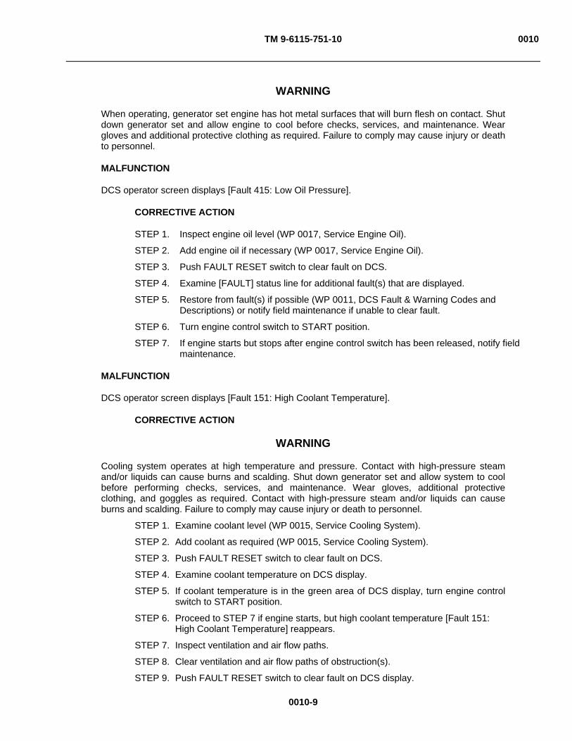
TM 9-6115-751-10 0010
0010-9
WARNING
When operating, generator set engine has hot metal surfaces that will burn flesh on contact. Shut down generator set and allow engine to cool before checks, services, and maintenance. Wear gloves and additional protective clothing as required. Failure to comply may cause injury or death to personnel.
MALFUNCTION
DCS operator screen displays [Fault 415: Low Oil Pressure].
CORRECTIVE ACTION
STEP 1. Inspect engine oil level (WP 0017, Service Engine Oil).
STEP 2. Add engine oil if necessary (WP 0017, Service Engine Oil).
STEP 3. Push FAULT RESET switch to clear fault on DCS.
STEP 4. Examine [FAULT] status line for additional fault(s) that are displayed.
STEP 5. Restore from fault(s) if possible (WP 0011, DCS Fault & Warning Codes and Descriptions) or notify field maintenance if unable to clear fault.
STEP 6. Turn engine control switch to START position.
STEP 7. If engine starts but stops after engine control switch has been released, notify field maintenance.
MALFUNCTION
DCS operator screen displays [Fault 151: High Coolant Temperature].
CORRECTIVE ACTION
WARNING
Cooling system operates at high temperature and pressure. Contact with high-pressure steam and/or liquids can cause burns and scalding. Shut down generator set and allow system to cool before performing checks, services, and maintenance. Wear gloves, additional protective clothing, and goggles as required. Contact with high-pressure steam and/or liquids can cause burns and scalding. Failure to comply may cause injury or death to personnel.
STEP 1. Examine coolant level (WP 0015, Service Cooling System).
STEP 2. Add coolant as required (WP 0015, Service Cooling System).
STEP 3. Push FAULT RESET switch to clear fault on DCS.
STEP 4. Examine coolant temperature on DCS display.
STEP 5. If coolant temperature is in the green area of DCS display, turn engine control switch to START position.
STEP 6. Proceed to STEP 7 if engine starts, but high coolant temperature [Fault 151: High Coolant Temperature] reappears.
STEP 7. Inspect ventilation and air flow paths.
STEP 8. Clear ventilation and air flow paths of obstruction(s).
STEP 9. Push FAULT RESET switch to clear fault on DCS display.
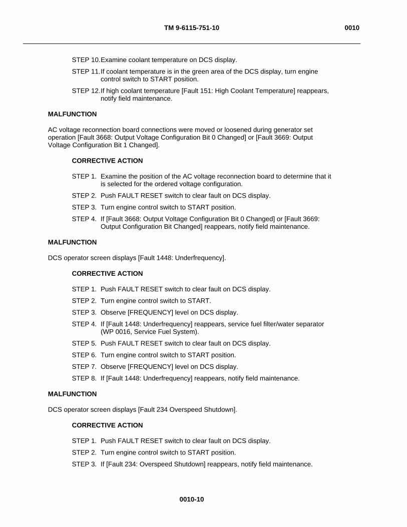
TM 9-6115-751-10 0010
0010-10
STEP 10. Examine coolant temperature on DCS display.
STEP 11. If coolant temperature is in the green area of the DCS display, turn engine control switch to START position.
STEP 12. If high coolant temperature [Fault 151: High Coolant Temperature] reappears, notify field maintenance.
MALFUNCTION
AC voltage reconnection board connections were moved or loosened during generator set operation [Fault 3668: Output Voltage Configuration Bit 0 Changed] or [Fault 3669: Output Voltage Configuration Bit 1 Changed].
CORRECTIVE ACTION
STEP 1. Examine the position of the AC voltage reconnection board to determine that it is selected for the ordered voltage configuration.
STEP 2. Push FAULT RESET switch to clear fault on DCS display.
STEP 3. Turn engine control switch to START position.
STEP 4. If [Fault 3668: Output Voltage Configuration Bit 0 Changed] or [Fault 3669: Output Configuration Bit Changed] reappears, notify field maintenance.
MALFUNCTION
DCS operator screen displays [Fault 1448: Underfrequency].
CORRECTIVE ACTION
STEP 1. Push FAULT RESET switch to clear fault on DCS display.
STEP 2. Turn engine control switch to START.
STEP 3. Observe [FREQUENCY] level on DCS display.
STEP 4. If [Fault 1448: Underfrequency] reappears, service fuel filter/water separator (WP 0016, Service Fuel System).
STEP 5. Push FAULT RESET switch to clear fault on DCS display.
STEP 6. Turn engine control switch to START position.
STEP 7. Observe [FREQUENCY] level on DCS display.
STEP 8. If [Fault 1448: Underfrequency] reappears, notify field maintenance.
MALFUNCTION
DCS operator screen displays [Fault 234 Overspeed Shutdown].
CORRECTIVE ACTION
STEP 1. Push FAULT RESET switch to clear fault on DCS display.
STEP 2. Turn engine control switch to START position.
STEP 3. If [Fault 234: Overspeed Shutdown] reappears, notify field maintenance.
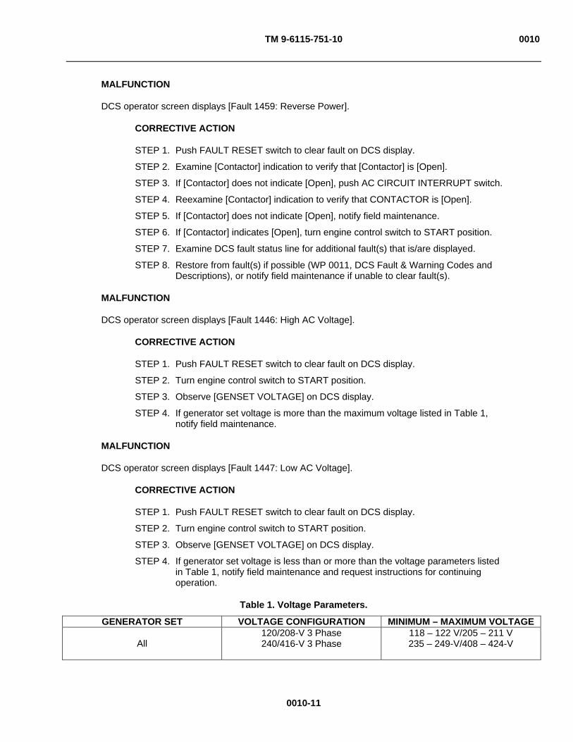
TM 9-6115-751-10 0010
0010-11
MALFUNCTION
DCS operator screen displays [Fault 1459: Reverse Power].
CORRECTIVE ACTION
STEP 1. Push FAULT RESET switch to clear fault on DCS display.
STEP 2. Examine [Contactor] indication to verify that [Contactor] is [Open].
STEP 3. If [Contactor] does not indicate [Open], push AC CIRCUIT INTERRUPT switch.
STEP 4. Reexamine [Contactor] indication to verify that CONTACTOR is [Open].
STEP 5. If [Contactor] does not indicate [Open], notify field maintenance.
STEP 6. If [Contactor] indicates [Open], turn engine control switch to START position.
STEP 7. Examine DCS fault status line for additional fault(s) that is/are displayed.
STEP 8. Restore from fault(s) if possible (WP 0011, DCS Fault & Warning Codes and Descriptions), or notify field maintenance if unable to clear fault(s).
MALFUNCTION
DCS operator screen displays [Fault 1446: High AC Voltage].
CORRECTIVE ACTION
STEP 1. Push FAULT RESET switch to clear fault on DCS display.
STEP 2. Turn engine control switch to START position.
STEP 3. Observe [GENSET VOLTAGE] on DCS display.
STEP 4. If generator set voltage is more than the maximum voltage listed in Table 1, notify field maintenance.
MALFUNCTION
DCS operator screen displays [Fault 1447: Low AC Voltage].
CORRECTIVE ACTION
STEP 1. Push FAULT RESET switch to clear fault on DCS display.
STEP 2. Turn engine control switch to START position.
STEP 3. Observe [GENSET VOLTAGE] on DCS display.
STEP 4. If generator set voltage is less than or more than the voltage parameters listed in Table 1, notify field maintenance and request instructions for continuing operation.
Table 1. Voltage Parameters.
GENERATOR SET VOLTAGE CONFIGURATION MINIMUM – MAXIMUM VOLTAGE
All 120/208-V 3 Phase 240/416-V 3 Phase
118 – 122 V/205 – 211 V 235 – 249-V/408 – 424-V
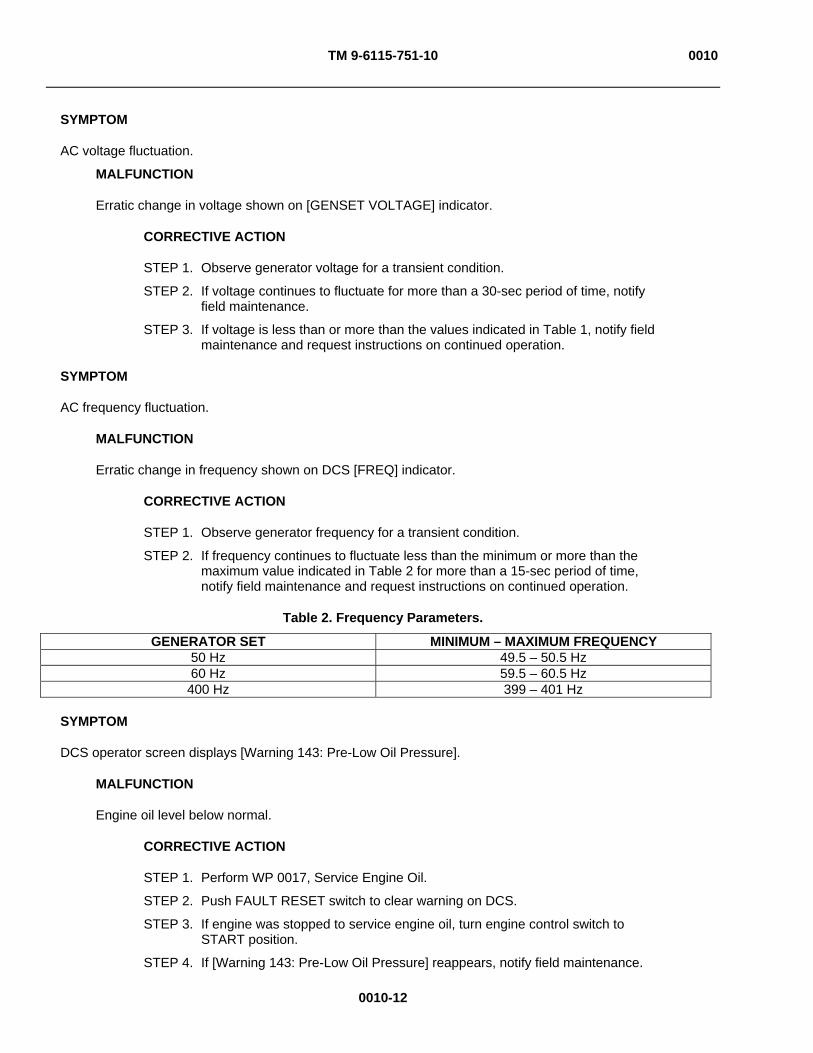
TM 9-6115-751-10 0010
0010-12
SYMPTOM
AC voltage fluctuation.
MALFUNCTION
Erratic change in voltage shown on [GENSET VOLTAGE] indicator.
CORRECTIVE ACTION
STEP 1. Observe generator voltage for a transient condition.
STEP 2. If voltage continues to fluctuate for more than a 30-sec period of time, notify field maintenance.
STEP 3. If voltage is less than or more than the values indicated in Table 1, notify field maintenance and request instructions on continued operation.
SYMPTOM
AC frequency fluctuation.
MALFUNCTION
Erratic change in frequency shown on DCS [FREQ] indicator.
CORRECTIVE ACTION
STEP 1. Observe generator frequency for a transient condition.
STEP 2. If frequency continues to fluctuate less than the minimum or more than the maximum value indicated in Table 2 for more than a 15-sec period of time, notify field maintenance and request instructions on continued operation.
Table 2. Frequency Parameters.
GENERATOR SET MINIMUM – MAXIMUM FREQUENCY 50 Hz 49.5 – 50.5 Hz 60 Hz 59.5 – 60.5 Hz
400 Hz 399 – 401 Hz
SYMPTOM
DCS operator screen displays [Warning 143: Pre-Low Oil Pressure].
MALFUNCTION
Engine oil level below normal.
CORRECTIVE ACTION
STEP 1. Perform WP 0017, Service Engine Oil.
STEP 2. Push FAULT RESET switch to clear warning on DCS.
STEP 3. If engine was stopped to service engine oil, turn engine control switch to START position.
STEP 4. If [Warning 143: Pre-Low Oil Pressure] reappears, notify field maintenance.

TM 9-6115-751-10 0010
0010-13
MALFUNCTION
Improper grade of oil for conditions.
CORRECTIVE ACTION
STEP 1. Perform WP 0017, Service Engine Oil.
STEP 2. Push FAULT RESET switch to clear warning on DCS.
STEP 3. If engine was stopped to service engine oil, turn engine control switch to START position.
STEP 4. If [Warning 143: Pre-Low Oil Pressure] reappears, notify field maintenance and request instructions on continued operation.
SYMPTOM
DCS operator screen displays [Warning 146: Pre-High Coolant Temperature].
MALFUNCTION
Coolant temperature lower than FAULT condition but higher than normal.
CORRECTIVE ACTION
WARNING
Flying debris or material may enter eyes or strike the face. Wear appropriate eye/face protection while performing maintenance tasks. Failure to comply may cause injury or death to personnel.
Operating generator set with unit doors open or panels removed exposes personnel to a high noise level. Close unit doors and replace panels or wear hearing protection while operating or working near an operating generator set. Failure to comply may cause injury or death to personnel.
When operating, generator set engine has hot metal surfaces that will burn flesh on contact. Shut down generator set and allow engine to cool before checks, services, and maintenance. Wear gloves and additional protective clothing as required. Failure to comply may cause injury or death to personnel.
STEP 1. Examine DCS panel to determine and note coolant temperature.
STEP 2. Examine coolant overflow bottle for coolant level midpoint between HIGH and LOW level marks.
STEP 3. If coolant level is visible, notify field maintenance.
STEP 4. If coolant level is not visible, notify field maintenance and request instructions on continued operation.
STEP 5. If [Warning 146: Pre-High Coolant Temp] continues, proceed to next malfunction.

TM 9-6115-751-10 0010
0010-14
MALFUNCTION
Obstructed ventilation and air flow paths.
CORRECTIVE ACTION
STEP 1. Inspect ventilation and air flow paths.
STEP 2. Clear ventilation and air flow paths of obstruction(s).
STEP 3. Push FAULT RESET switch to clear warning on DCS.
STEP 4. If [Warning 146: Pre-High Coolant Temp] continues, notify field maintenance and request instructions on continued operation.
SYMPTOM
DCS operator screen displays [Warning 1441: Low Fuel Level].
CAUTION
Complete draining of fuel from tank which results in engine shut down will introduce air to the combustion system. Restart of an engine in this condition is very difficult. Do not allow generator set to drain fuel tank. Failure to comply will cause damage to equipment.
MALFUNCTION
Fuel level greater than [Fault] condition level of 2% but less than 4%.
CORRECTIVE ACTION
STEP 1. Examine fuel level indication on DCS display.
STEP 2. If fuel level indicator is in the green area on the DCS display or there is no fuel level indicated, examine fuel level visually (WP 0016, Service Fuel System).
STEP 3. If fuel level is not visible, refill fuel tank (WP 0016, Service Fuel System).
STEP 4. If fuel level is visible, notify field maintenance.
STEP 5. Push FAULT RESET switch to clear [Warning 1441: Low Fuel Level].
STEP 6. If [Warning 1441: Low Fuel Level] reappears, notify field maintenance.
MALFUNCTION
Faulty fuel level sensor.
CORRECTIVE ACTION
STEP 1. Examine fuel level indication on DCS display.
STEP 2. If fuel level indicator is in the green area on the DCS display or there is no fuel level indicated, examine fuel level visually (WP 0016, Service Fuel System).
STEP 3. If fuel level is not visible, refill fuel tank (WP 0016, Service Fuel System).
STEP 4. If fuel level is visible, notify field maintenance.
STEP 5. Push FAULT RESET switch to clear [Warning 1441: Low Fuel Level].
STEP 6. If [Warning 1441: Low Fuel Level] reappears, notify field maintenance.

TM 9-6115-751-10 0010
0010-15
SYMPTOM
DCS operator screen displays [Warning 2936: Fuel Level Sensor High] or [Warning 2937: Fuel Level Sensor Low].
MALFUNCTION
Faulty fuel sensor.
CORRECTIVE ACTION
Notify field maintenance.
SYMPTOM
DCS operator screen displays [Warning 441: Low Battery Voltage], [Warning 1442: Weak Battery], [Warning 3662: Battery Discharge], or [Warning 3663: Winterization Kit Failure to Heat].
MALFUNCTION
Battery cables loose, damaged, corroded, or disconnected.
CORRECTIVE ACTION
WARNING
Metal jewelry can conduct electricity and become entangled in generator set components. Remove all jewelry and do not wear loose clothing when working on equipment. Failure to comply may cause injury or death to personnel.
STEP 1. Inspect battery cables and connections.
STEP 2. If battery cables and/or connections are loose, damaged, corroded, or disconnected, notify field maintenance.
STEP 3. If cables and connectors are serviceable, proceed to next malfunction.
MALFUNCTION
Faulty battery-charging alternator.
CORRECTIVE ACTION
Notify field maintenance.
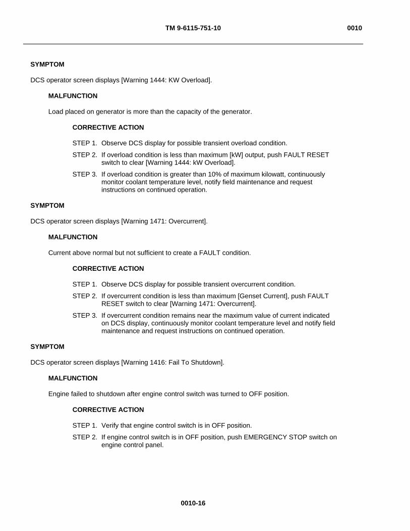
TM 9-6115-751-10 0010
0010-16
SYMPTOM
DCS operator screen displays [Warning 1444: KW Overload].
MALFUNCTION
Load placed on generator is more than the capacity of the generator.
CORRECTIVE ACTION
STEP 1. Observe DCS display for possible transient overload condition.
STEP 2. If overload condition is less than maximum [kW] output, push FAULT RESET switch to clear [Warning 1444: kW Overload].
STEP 3. If overload condition is greater than 10% of maximum kilowatt, continuously monitor coolant temperature level, notify field maintenance and request instructions on continued operation.
SYMPTOM
DCS operator screen displays [Warning 1471: Overcurrent].
MALFUNCTION
Current above normal but not sufficient to create a FAULT condition.
CORRECTIVE ACTION
STEP 1. Observe DCS display for possible transient overcurrent condition.
STEP 2. If overcurrent condition is less than maximum [Genset Current], push FAULT RESET switch to clear [Warning 1471: Overcurrent].
STEP 3. If overcurrent condition remains near the maximum value of current indicated on DCS display, continuously monitor coolant temperature level and notify field maintenance and request instructions on continued operation.
SYMPTOM
DCS operator screen displays [Warning 1416: Fail To Shutdown].
MALFUNCTION
Engine failed to shutdown after engine control switch was turned to OFF position.
CORRECTIVE ACTION
STEP 1. Verify that engine control switch is in OFF position.
STEP 2. If engine control switch is in OFF position, push EMERGENCY STOP switch on engine control panel.
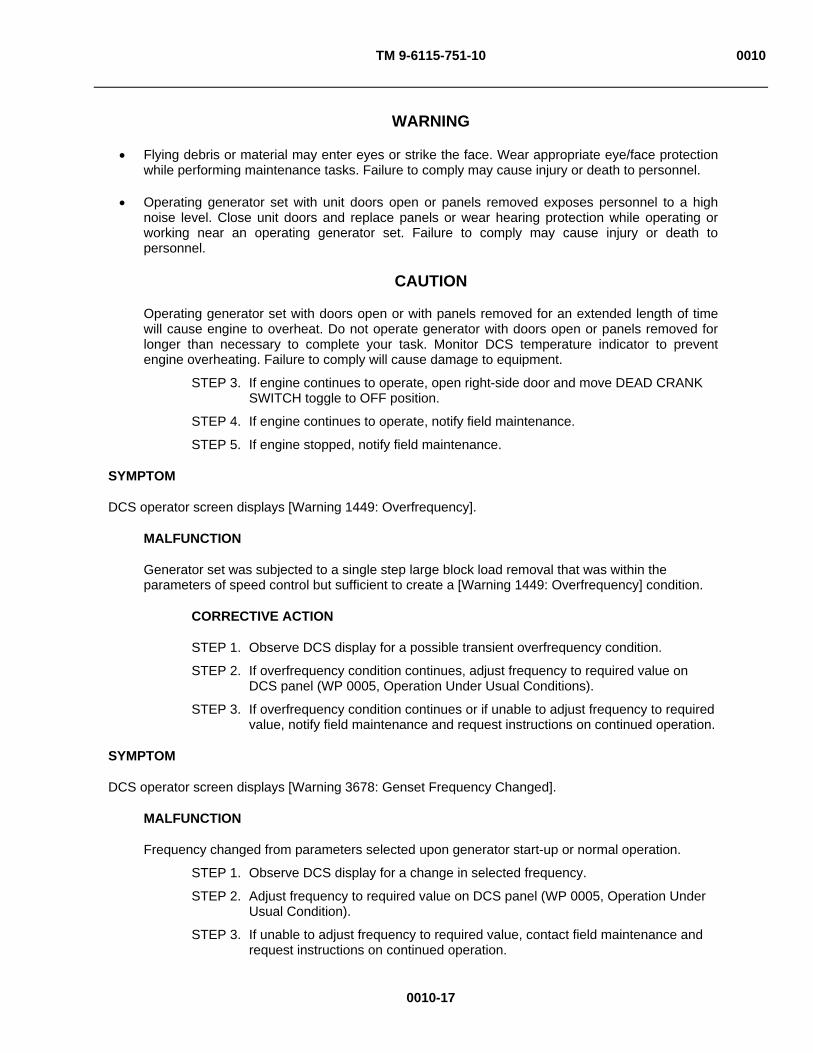
TM 9-6115-751-10 0010
0010-17
WARNING
Flying debris or material may enter eyes or strike the face. Wear appropriate eye/face protection while performing maintenance tasks. Failure to comply may cause injury or death to personnel.
Operating generator set with unit doors open or panels removed exposes personnel to a high noise level. Close unit doors and replace panels or wear hearing protection while operating or working near an operating generator set. Failure to comply may cause injury or death to personnel.
CAUTION
Operating generator set with doors open or with panels removed for an extended length of time will cause engine to overheat. Do not operate generator with doors open or panels removed for longer than necessary to complete your task. Monitor DCS temperature indicator to prevent engine overheating. Failure to comply will cause damage to equipment.
STEP 3. If engine continues to operate, open right-side door and move DEAD CRANK SWITCH toggle to OFF position.
STEP 4. If engine continues to operate, notify field maintenance.
STEP 5. If engine stopped, notify field maintenance.
SYMPTOM
DCS operator screen displays [Warning 1449: Overfrequency].
MALFUNCTION
Generator set was subjected to a single step large block load removal that was within the parameters of speed control but sufficient to create a [Warning 1449: Overfrequency] condition.
CORRECTIVE ACTION
STEP 1. Observe DCS display for a possible transient overfrequency condition.
STEP 2. If overfrequency condition continues, adjust frequency to required value on DCS panel (WP 0005, Operation Under Usual Conditions).
STEP 3. If overfrequency condition continues or if unable to adjust frequency to required value, notify field maintenance and request instructions on continued operation.
SYMPTOM
DCS operator screen displays [Warning 3678: Genset Frequency Changed].
MALFUNCTION
Frequency changed from parameters selected upon generator start-up or normal operation.
STEP 1. Observe DCS display for a change in selected frequency.
STEP 2. Adjust frequency to required value on DCS panel (WP 0005, Operation Under Usual Condition).
STEP 3. If unable to adjust frequency to required value, contact field maintenance and request instructions on continued operation.

TM 9-6115-751-10 0010
0010-18
SYMPTOM
DCS operator screen displays [Warning 1417: Power Down Failure].
MALFUNCTION
Processor fault [Warning 1417: Power Down Failure] message appears for longer than 10 min.
CORRECTIVE ACTION
STEP 1. Move main DC circuit breaker switch handle to OFF/TRIP position.
STEP 2. Return main DC circuit breaker switch handle to RESET-ON position.
STEP 3. Turn engine control switch to PRIME & RUN AUX FUEL or PRIME & RUN to reboot processor.
STEP 4. Push FAULT RESET switch to clear [Warning 1417: Power Down Failure].
STEP 5. If [Warning 1417: Power Down Failure] reappears, notify field maintenance.
SYMPTOM
DCS operator screen displays [Warning 1457: Fail To Synchronize].
MALFUNCTION
Generator set paralleling parameters improperly selected or greater than allowed by synchronizing detectors.
CORRECTIVE ACTION
STEP 1. Examine voltage and frequency options on DCS display to determine if they are selected for required values (WP 0005, Operation Under Usual Conditions).
STEP 2. Examine AC voltage reconnection boards on each generator to determine if they are selected for required values (WP 0005, Operation Under Usual Conditions).
STEP 3. Adjust voltage and frequency on operating generator sets to match required parameters (WP 0005, Operation Under Usual Conditions).
STEP 4. Repeat paralleling task (WP 0006, Parallel Operation).
STEP 5. If [Warning 1457: Fail To Synchronize] reappears, notify field maintenance].
SYMPTOM
DCS operator screen displays [Warning 3658: Switch Box Fail To Close].
MALFUNCTION
Paralleling operations are being conducted without a switch box.
NOTE
This warning cannot be cleared until the generator set has been shut down. Before generator set is to be restarted, push FAULT RESET to clear the warning.
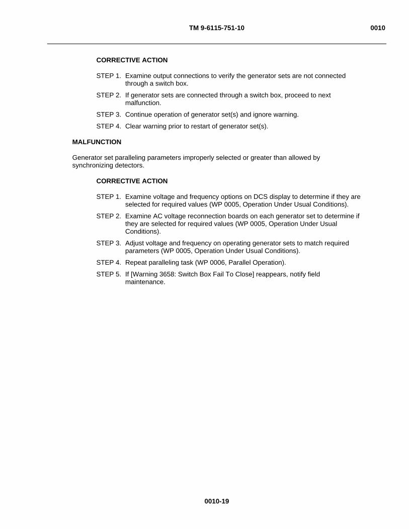
TM 9-6115-751-10 0010
0010-19
CORRECTIVE ACTION
STEP 1. Examine output connections to verify the generator sets are not connected through a switch box.
STEP 2. If generator sets are connected through a switch box, proceed to next malfunction.
STEP 3. Continue operation of generator set(s) and ignore warning.
STEP 4. Clear warning prior to restart of generator set(s).
MALFUNCTION
Generator set paralleling parameters improperly selected or greater than allowed by synchronizing detectors.
CORRECTIVE ACTION
STEP 1. Examine voltage and frequency options on DCS display to determine if they are selected for required values (WP 0005, Operation Under Usual Conditions).
STEP 2. Examine AC voltage reconnection boards on each generator set to determine if they are selected for required values (WP 0005, Operation Under Usual Conditions).
STEP 3. Adjust voltage and frequency on operating generator sets to match required parameters (WP 0005, Operation Under Usual Conditions).
STEP 4. Repeat paralleling task (WP 0006, Parallel Operation).
STEP 5. If [Warning 3658: Switch Box Fail To Close] reappears, notify field maintenance.

TM 9-6115-751-10 0010
0010-20
SYMPTOM
Engine exhaust smoking.
MALFUNCTION
Engine emits white exhaust smoke.
WARNING
Flying debris or material may enter eyes or strike the face. Wear appropriate eye/face protection while performing maintenance tasks. Failure to comply may cause injury or death to personnel.
Operating generator set with unit doors open or panels removed exposes personnel to a high noise level. Close unit doors and replace panels or wear hearing protection while operating or working near an operating generator set. Failure to comply may cause injury or death to personnel.
CAUTION
Operating generator set with doors open or with panels removed for an extended length of time will cause engine to overheat. Do not operate generator with doors open or panels removed for longer than necessary to complete your task. Monitor DCS temperature indicator to prevent engine overheating. Failure to comply will cause damage to equipment.
CORRECTIVE ACTION
STEP 1. Inspect for evidence of water in fuel tank.
STEP 2. Inspect fuel filter/water separator for contamination (WP 0016, Service Fuel System).
STEP 3. If contamination appears, drain fuel filter/water separator (WP 0016, Service Fuel System).
STEP 4. Turn engine control switch to START position.
STEP 5. If malfunction continues, notify field maintenance and request instructions on continued operation.
MALFUNCTION
Engine emits black exhaust smoke.
CORRECTIVE ACTION
STEP 1. Examine [GENSET CURRENT] parameters for high load condition.
STEP 2. If [GENSET CURRENT] parameters are within limits, service air cleaner element (WP 0014, Service Air Cleaner).
STEP 3. Turn engine control switch to START position.
STEP 4. If malfunction continues, notify field maintenance and request instructions on continued operation.
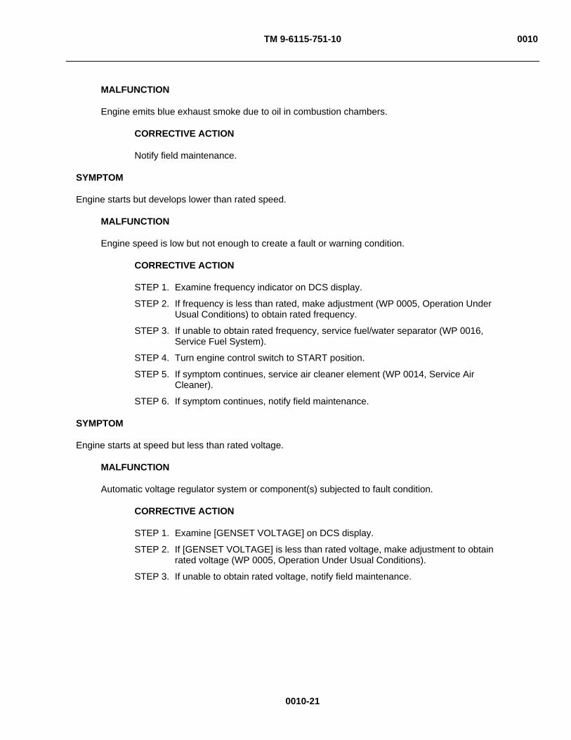
TM 9-6115-751-10 0010
0010-21
MALFUNCTION
Engine emits blue exhaust smoke due to oil in combustion chambers.
CORRECTIVE ACTION
Notify field maintenance.
SYMPTOM
Engine starts but develops lower than rated speed.
MALFUNCTION
Engine speed is low but not enough to create a fault or warning condition.
CORRECTIVE ACTION
STEP 1. Examine frequency indicator on DCS display.
STEP 2. If frequency is less than rated, make adjustment (WP 0005, Operation Under Usual Conditions) to obtain rated frequency.
STEP 3. If unable to obtain rated frequency, service fuel/water separator (WP 0016, Service Fuel System).
STEP 4. Turn engine control switch to START position.
STEP 5. If symptom continues, service air cleaner element (WP 0014, Service Air Cleaner).
STEP 6. If symptom continues, notify field maintenance.
SYMPTOM
Engine starts at speed but less than rated voltage.
MALFUNCTION
Automatic voltage regulator system or component(s) subjected to fault condition.
CORRECTIVE ACTION
STEP 1. Examine [GENSET VOLTAGE] on DCS display.
STEP 2. If [GENSET VOLTAGE] is less than rated voltage, make adjustment to obtain rated voltage (WP 0005, Operation Under Usual Conditions).
STEP 3. If unable to obtain rated voltage, notify field maintenance.
TM 9-6115-751-10 0010
0010-22
WARNING
Ensure the frequency of any device powered by the GFCI convenience receptacle matches the frequency of the generator set. Failure to comply can cause serious injury or death to personnel.
NOTE
Power is only available from the GFCI CONVENIENCE RECEPTACLE when the generator set is operating and the [CONTACTOR] is [CLOSED].
SYMPTOM
Power not available at GFCI CONVENIENCE RECEPTACLE.
MALFUNCTION
GFCI CONVENIENCE RECEPTACLE has been subjected to a ground fault condition.
CORRECTIVE ACTION
STEP 1. If generator is operating and the [CONTACTOR] is [CLOSED], push RESET switches located on the face of the GFCI receptacle.
STEP 2. If symptom continues, notify field maintenance.
END OF WORK PACKAGE

TM 9-6115-751-10 0011
0011-1
OPERATOR MAINTENANCE
AMMPS 15KW GENERATOR SET
DCS FAULT & WARNING CODES AND DESCRIPTIONS
INITIAL SETUP:
Test Equipment
Not Applicable
Tools and Special Tools
Not Applicable
Materials/Parts
Not Applicable
Personnel Required
Not Applicable
References
WP 0005, Operation Under Usual Conditions
WP 0010, Troubleshooting Procedures
WP 0014, Service Air Cleaner
WP 0015, Service Cooling System
WP 0016, Service Fuel System
WP 0017, Service Engine Oil
Equipment Conditions
Not Applicable
DCS FAULT & WARNING CODES AND DESCRIPTIONS
Table 1 lists the fault and warning code numbers and DCS panel text displayed on the control panel. Fault or warning codes to be addressed by the operator are listed first followed by the fault or warning codes that must be addressed by field maintenance personnel. When displayed, the operator is to respond to these codes IAW the procedures found in this TM. The WP number(s) to be referenced is (are) listed in the Action column. If the initial response of the operator to terminate the code is ineffective, notify field maintenance.
Table 1. DCS Fault and Warning Codes and Descriptions.
MESSAGE WORD CORRECTIVE ACTION FAULT CODES TO BE ADDRESSED BY OPERATOR
FAULT CODES TO BE ADDRESSED BY OPERATOR
Fault 151: High Coolant Temperature WP 0015, Service Cooling System; WP 0010, Troubleshooting Procedures.
Fault 234: Overspeed Shutdown WP 0010, Troubleshooting Procedures. Fault 359: Fail to Start WP 0016, Service Fuel System;
WP 0010, Troubleshooting Procedures. Fault 415: Low Oil Pressure WP 0017, Service Engine Oil;
WP 0010, Troubleshooting Procedures. Fault 1433: Local E-Stop WP 0010, Troubleshooting Procedures, Engine fails to
crank. Fault 1434: Remote E-Stop WP 0010, Troubleshooting Procedures, Engine fails to
crank. Fault 1438: Fail To Crank WP 0010, Troubleshooting Procedures, Engine fails to
crank. Fault 1443: Dead Battery WP 0010, Troubleshooting Procedures, Engine fails to
crank.

TM 9-6115-751-10 0011
0011-2
Table 1. DCS Fault and Warning Codes and Descriptions — Continued.
MESSAGE WORD CORRECTIVE ACTION FAULT CODES TO BE ADDRESSED BY OPERATOR
FAULT CODES TO BE ADDRESSED BY OPERATOR
Fault 1445: Short Circuit WP 0005, Operation Under Usual Conditions; WP 0010, Troubleshooting Procedures.
Fault 1446: High AC Voltage WP 0010, Troubleshooting Procedures, Generator was subjected to an over-voltage condition.
Fault 1447: Low AC Voltage WP 0010, Troubleshooting Procedures, Generator was subjected to an under-voltage condition.
Fault 1448: Under frequency WP 0014, Service Air Cleaner; WP 0016, Service Fuel System; WP 0010, Troubleshooting Procedures.
Fault 1452: Genset CB Fail to Close WP 0010, Troubleshooting Procedures. Fault 1453: Genset CB Fail to Open WP 0010, Troubleshooting Procedures. Fault 1459: Reverse Power WP 0010, Troubleshooting Procedures. Fault 1472: Over Current WP 0005, Operation Under Usual Conditions. Fault 1918: Fuel Level Low WP 0016, Service Fuel System;
WP 0010, Troubleshooting Procedures. Fault 3668: Output Voltage Configuration Bit 0 Changed
WP 0010, Troubleshooting Procedures.
Fault 3669: Output Voltage Configuration Bit 1 Changed
WP 0010, Troubleshooting Procedures.
FAULT CODES TO BE ADDRESSED BY FIELD MAINTENANCE
FAULT CODES TO BE ADDRESSED BY FIELD MAINTENANCE
Fault 115: Speed Signal Lost Contact field maintenance. Fault 1461: Loss of Field Contact field maintenance. Fault 2335: Excitation Fault Contact field maintenance. Fault 2914: Genset AC Meter Failed Contact field maintenance. Fault 2972: Field Overload Contact field maintenance. Fault 3664: Invalid Genset Configuration Contact field maintenance. Fault 3665: Invalid Voltage Configuration Contact field maintenance. Fault 3673: Convenience Receptacle AC Meter Failed
Contact field maintenance.
Fault 3677: Genset Config Factory Test Fault Contact field maintenance. WARNING CODES TO BE ADDRESSED BY OPERATOR
WARNING CODES TO BE ADDRESSED BY OPERATOR
Warning 143: Pre-Low Oil Pressure WP 0017, Service Engine Oil; WP 0010, Troubleshooting Procedures.
Warning 146: Pre-High Coolant Temperature WP 0015, Service Cooling System; WP 0010, Troubleshooting Procedures.
Warning 441: Low Battery Voltage WP 0010, Troubleshooting Procedures. Warning 1131: Battleshort Active WP 0005, Operation Under Usual Conditions;
WP 0010, Troubleshooting Procedures. Warning 1416: Fail to Shutdown WP 0010, Troubleshooting Procedures. Warning 1417: Power Down Failure WP 0010, Troubleshooting Procedures. Warning 1441: Low Fuel Level WP 0015, Service Fuel System;
WP 0010, Troubleshooting Procedures. Warning 1442: Weak Battery WP 0010, Troubleshooting Procedures. Warning 1444: KW Overload WP 0005, Operation Under Usual Conditions;
WP 0010, Troubleshooting Procedures. Warning 1449: Over frequency WP 0005, Operation Under Usual Conditions;
WP 0010, Troubleshooting Procedures.

TM 9-6115-751-10 0011
0011-3/4 blank
Table 1. DCS Fault and Warning Codes and Descriptions — Continued.
MESSAGE WORD CORRECTIVE ACTION WARNING CODES TO BE ADDRESSED BY OPERATOR
WARNING CODES TO BE ADDRESSED BY OPERATOR
Warning 1457: Fail To Synchronize WP 0010, Troubleshooting Procedures. Warning 1471: Over current WP 0005, Operation Under Usual Conditions;
WP 0010, Troubleshooting Procedures. Warning 1992: High Speed Warning WP 0010, Troubleshooting Procedures. Warning 2917: Genset Bus Voltage High WP 0010, Troubleshooting Procedures. Warning 2936: Fuel Level Sensor High WP 0010, Troubleshooting Procedures. Warning 2937: Fuel Level Sensor Low WP 0010 Troubleshooting Procedures. Warning 3658: Switch Box Fail To Close WP 0010, Troubleshooting Procedures. Warning 3663: Winterization Kit Failure to Heat WP 0010, Troubleshooting Procedures. Warning 3678: Genset Frequency Changed WP 0010, Troubleshooting Procedures. WARNING CODES TO BE ADDRESSED BY FIELD MAINTENANCE
WARNING CODES TO BE ADDRESSED BY FIELD MAINTENANCE
Warning 442: High Battery Voltage Contact field maintenance. Warning 1451: Genset/Bus Voltage Mismatch Contact field maintenance. Warning 1456: Bus Out Of Synchronization Range Contact field maintenance. Warning 1458: Synchronization Phase Rotation Mismatch
Contact field maintenance.
Warning 1469: Speed/Hz Mismatch Contact field maintenance. Warning 1689: Real Time Clock Contact field maintenance. Warning 2915: Genset Bus AC Meter Failed Contact field maintenance. Warning 2967: Governor Fault Contact field maintenance.Warning 2968: AVR Fault Contact field maintenance.Warning 3661: Maintenance Item is Active Contact field maintenance. Warning 3662: Battery Discharge Contact field maintenance. Warning 3666: Master Control Switch Configuration Contact field maintenance. Warning 3667: Voltage Configuration Change Contact field maintenance. Warning 3671: Low Genset Battery Voltage During Winterization
Contact field maintenance.
Warning 3672: Automatic Field Flash Not Complete Contact field maintenance. Warning 3674: Genset Configuration Change Contact field maintenance. Warning 3676: Common Alarm Input Fault Contact field maintenance.
END OF WORK PACKAGE

TM 9-6115-751-10
CHAPTER 4
MAINTENANCE INSTRUCTIONS FOR
AMMPS 15KW GENERATOR SET
TM 9-6115-751-10
CHAPTER 4
MAINTENANCE INSTRUCTIONS
WORK PACKAGE INDEX
Title WP Sequence No.
PMCS INTRODUCTION ...................................................................................................................................... 0012
PMCS................................................................................................................................................................... 0013
SERVICE AIR CLEANER .................................................................................................................................... 0014
SERVICE COOLING SYSTEM............................................................................................................................ 0015
SERVICE FUEL SYSTEM ................................................................................................................................... 0016
SERVICE ENGINE OIL........................................................................................................................................ 0017

TM 9-6115-751-10 0012
0012-1
OPERATOR MAINTENANCE
AMMPS 15KW GENERATOR SET
PMCS INTRODUCTION
INTRODUCTION
This section contains information that you will need to perform operator PMCS. Steps are included to help you perform these procedures easily and quickly. PMCS consists of scheduled maintenance items used to make sure the AMMPS 15 kW generator sets are ready for operation at all times. Inspect the system regularly and carefully so that you can find, correct, or prevent any defects.
GENERAL
PMCS is performed to keep the equipment in operating condition. The checks are used to find, correct, or report problems. Pay attention to warning and caution statements. A warning indicates the possibility of injury or death to personnel. A caution means the equipment could be damaged.
Before beginning operation of the equipment, perform Before (B) PMCS.
During operation, perform During (D) PMCS.
After operation, perform After (A) PMCS.
EXPLANATION OF THE COLUMNS FOUND IN PMCS TABLE
Column (1) – Item No. The item number lists the checks and services in the order they are to be performed. This column will be used as a source of item for the TM Number Column on DA Form 2404, Equipment Inspection and Maintenance Worksheet or DA Form 5988E (electronic version), Equipment Inspection and Maintenance Worksheet, in recording the result of the PMCS.
Column (2) – Interval. References when the PMCS should be performed.
Column (3) – Item to be checked or serviced. Identifies the portion of the system to be inspected.
Column (4) – Procedure. Provides the procedures for performing the checks.
Column (5) – Equipment Not Ready/Available If. Contains the criteria that will render the system incapable of performing its primary mission. If the system does not perform as required, refer to Chapter 3, Operator Troubleshooting Procedures (WP 0009, Troubleshooting Index). If equipment appears to be malfunctioning and the problem cannot be fixed, immediately report it to your supervisor and report it on DA Form 2404, Equipment Inspection and Maintenance Worksheet.
CORROSION PREVENTION AND CONTROL (CPC)
Corrosion Prevention and Control (CPC) of Army materiel is a continuing concern. It is important that any corrosion problems with this item be reported so that the problem can be corrected and improvements can be made to prevent the problem in future items.
Corrosion specifically occurs with metals. It is an electrochemical process that causes the degradation of metals. It is commonly caused by exposure to moisture, acids, bases, or salts. An example is the rusting of iron. Corrosion damage in metals can be seen, depending on the metal, as tarnishing, pitting, fogging, surface residue, and/or cracking.
TM 9-6115-751-10 0012
0012-2
Plastics, composites, and rubbers can also degrade. Degradation is caused by thermal (heat), oxidation (oxygen), solvation (solvents), or photolytic (light, typically Ultraviolet (UV)) processes. The most common exposures are excessive heat or light. Damage from these processes will appear as cracking, softening, swelling, and/or breaking. SF 368, Product Quality Deficiency Report, should be submitted to the address specified in DA PAM 750-8, The Army Maintenance Management System (TAMMS) Users Manual.
For aircraft TMs, this information shall include a reference to TM 1-1500-344-23, volumes 1 through 4 (Cleaning and Corrosion Control).
Rust Definition
Rust is defined as any various scaly or powdery reddish-brown or reddish-yellow materials that form on iron and iron-coated materials in the presence of moisture, deteriorating as a result of disuse or neglect.
Deterioration Definition
Deterioration is defined as any condition that causes material to be impaired or lessens the quality or value of the material.
Cracking Definition
Cracking is defined as when material is found to be split or broken, either completely or partially.
INSPECTION
Look for signs of problems or trouble. Most problems can be detected by sight, touch, smell, or sound. Be alert when around the AMMPS 15 kW generator set.
Inspect to ensure that all components are in good condition. Are they correctly assembled, stowed, or secured? Are any components worn, corroded, or rusty? Correct any problems found or notify your immediate supervisor.
There are common items on the generator set that should be checked. These include the following:
Bolts, clamps, screws, and nuts: Continuously inspect for looseness. Inspect for chipped paint, bare metal, rust, and corrosion around bolt and screw heads and nuts. Replace as necessary. Tighten hardware as required. If tools are required, notify field maintenance.
Welds: Some components of the AMMPS 15 kW generator set are welded. To inspect welds, look for chipped paint, rust, corrosion, and gaps. When these conditions are found, notify field maintenance.
TM 9-6115-751-10 0012
0012-3
WARNING NATO slave receptacle is electrically live at all times and is not protected by a fuse.
Disconnecting main DC circuit breaker does not ensure the circuit is dead. This circuit is only dead when the batteries are fully disconnected. Disconnect both batteries before performing maintenance on the slave receptacle. Failure to comply may cause injury or death to personnel.
Metal jewelry can conduct electricity and become entangled in generator set components. Remove all jewelry and do not wear loose clothing when working on equipment. Failure to comply may cause injury or death to personnel.
High voltage is produced when generator set is in operation. Never attempt to start the generator set unless it is properly grounded. Do not ground yourself in standing water. Never attempt to connect or disconnect load cables while the generator set is operating. Failure to comply may cause injury or death to personnel.
While inspecting the operation of the generator set, do not inadvertently reach in the generator set. Failure to comply may causey injury or death to personnel.
Electrical wires, connectors, and harnesses: Tighten loose connections. Inspect for cracked or broken insulation, bare wires, and broken connectors. If any are found, notify field maintenance.
Hoses and fluid lines: Inspect for wear, damage, and leaks. Ensure clamps and fittings are tight. Wet spots indicate a leak. A stain by a fitting or connector can also mean a leak. When this is found, notify field maintenance.
CLEANING AND LUBRICATION
Proper cleaning and lubrication can aid in avoiding possible problems or trouble. Make it a habit to do the following:
CAUTION
Follow all cleaning and lubrication instructions carefully. Failure to comply may cause damage to equipment.
Under harsh environmental conditions, conduct PMCS more frequently.
Use only the recommended cleaning solutions and lubricants found in the Expendable and Durable Items List (WP 0021, Expendable and Durable Items List).
Clean the screen of the DCS using the proper lens paper found in the Expendable and Durable Items List (WP 0021, Expendable and Durable Items List).
Oil Filters
Oil filters shall be serviced/cleaned/changed, as applicable, when:
They are known to be contaminated or clogged, or
Service is recommended by AOAP laboratory analysis, or
At prescribed hardtime intervals.

TM 9-6115-751-10 0012
0012-4
AOAP Sampling Intervals
Engine oil/transmission oil/hydraulic fluids must be sampled at 60 days (Active Army and Reserve NG) as prescribed by DA PAM 750-8, TAMMS Users Manual. See Sample Oil Task, Service Engine Oil (WP 0017, Service Engine Oil).
Warranty Hardtime
For equipment under manufacturer's warranty, hardtime oil service intervals shall be followed. Intervals shall be shortened if lubricants are known to be contaminated or if operation is under adverse conditions (such as longer-than-usual operating hours, extended idling periods, extreme dust).
FLUID LEAKAGE
WARNING
Fuel is combustible and toxic to eyes, skin, and respiratory tract. Skin and eye protection are required when working in contact with fuel. Avoid repeated or prolonged contact. Provide adequate ventilation. Operators are to wash skin and change clothing promptly if in contact with fuel. Failure to comply may cause injury or death to personnel.
CAUTION
When operating with Class I or II leaks, continue to check fluid level as required by PMCS. Class III leaks should be reported to your supervisor immediately. Any Class I, II, or III fuel leak requires equipment shut down. Failure to comply may cause damage to equipment.
It is necessary to know how fluid leakage affects the status of the 15 kW generator set. Following are types/classes of leakage you need to know to determine the status of the 15 kW generator set. Learn these leakage definitions and remember: when in doubt, notify your supervisor. Equipment operation is allowed with minor leakage (Class I or II). Consideration must be given to fluid capacity in the item/system being checked/inspected. When in doubt, notify your supervisor.
Any Class I, II, or III fuel leak requires equipment shut down.
Class III leaks should be reported immediately to your supervisor.
(1) Class I: Seepage of fluid (as indicated by wetness or discoloration) not great enough to form drops.
(2) Class II: Leakage of fluid great enough to form drops but not enough to cause drops to drip from item being checked/inspected.
(3) Class III: Leakage of fluid great enough to form three drops that fall from item being checked/inspected within 5 sec.
END OF WORK PACKAGE
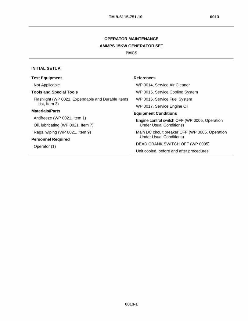
TM 9-6115-751-10 0013
0013-1
OPERATOR MAINTENANCE
AMMPS 15KW GENERATOR SET
PMCS
INITIAL SETUP:
Test Equipment
Not Applicable
Tools and Special Tools
Flashlight (WP 0021, Expendable and Durable Items List, Item 3)
Materials/Parts
Antifreeze (WP 0021, Item 1)
Oil, lubricating (WP 0021, Item 7)
Rags, wiping (WP 0021, Item 9)
Personnel Required
Operator (1)
References
WP 0014, Service Air Cleaner
WP 0015, Service Cooling System
WP 0016, Service Fuel System
WP 0017, Service Engine Oil
Equipment Conditions
Engine control switch OFF (WP 0005, Operation Under Usual Conditions)
Main DC circuit breaker OFF (WP 0005, Operation Under Usual Conditions)
DEAD CRANK SWITCH OFF (WP 0005)
Unit cooled, before and after procedures

TM 9-6115-751-10 0013
Figure 1. Rear View.
0013-2
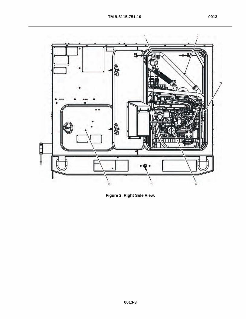
TM 9-6115-751-10 0013
Figure 2. Right Side View.
0013-3
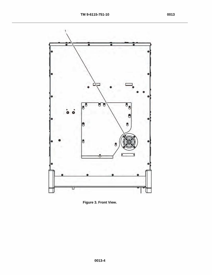
TM 9-6115-751-10 0013
Figure 3. Front View.
0013-4
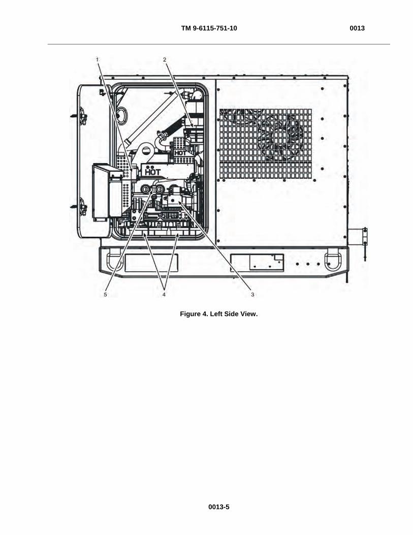
TM 9-6115-751-10 0013
Figure 4. Left Side View.
0013-5

TM 9-6115-751-10 0013
0013-6
Table 1. PMCS for the AMMPS 15 kW Generator Set.
ITEM NO. INTERVAL
ITEM TO BE CHECKED OR SERVICED PROCEDURE
EQUIPMENT NOT READY/AVAILABLE IF:
WARNING
High voltage is produced when generator set is in operation. Never attempt to start the generator set unless it is properly grounded. Do not ground yourself in standing water. Never attempt to connect or disconnect load cables while the generator set is operating. Failure to comply may cause injury or death to personnel.
Fuel is combustible and toxic to eyes, skin, and respiratory tract. Skin and eye protection are required when working in contact with fuel. Avoid repeated or prolonged contact. Provide adequate ventilation. Operators are to wash skin and change clothing promptly if in contact with fuel. Failure to comply may cause injury or death to personnel.
Fuels used in the generator set are combustible. Do not smoke or use open fire when performing maintenance. Fire and possible explosion may result. Failure to comply may cause injury or death to personnel and damage to equipment.
Fuels used in the generator set are combustible. Ensure fuel source grounding strap is connected to unit fuel fill grounding stud (fuel fill static ground). When filling the fuel tank, maintain metal-to-metal contact between filler nozzle and fuel tank opening to eliminate ESD. Fire and possible explosion can result. Failure to comply may cause injury or death to personnel.
Do not operate generator set if any fuel leaks are present. Fuel is combustible. Always perform PMCS before operation. Failure to comply may cause injury or death to personnel.
Exhaust discharge contains deadly gases, including carbon monoxide. Exhaust gases are most dangerous in places with poor ventilation. Do not operate generator set in an enclosed area unless exhaust discharge is properly vented. Failure to comply may cause injury or death to personnel.
Ensure the frequency of any device powered by the GFCI convenience receptacle matches the frequency of the generator set. Failure to comply may cause injury or death to personnel.
Power is available to the convenience receptacle when the main contactor is open. Avoid accidental contact. Electrocution is possible. Failure to comply may cause injury or death to personnel.
NATO slave receptacle is electrically live at all times and is not protected by a fuse. Disconnecting main DC circuit breaker does not ensure the circuit is dead. This circuit is only dead when the batteries are fully disconnected. Disconnect both batteries before performing maintenance on the slave receptacle. Failure to comply may cause injury or death to personnel
Batteries give off combustible gas. Do not smoke or use open flame when performing maintenance. Failure to comply may cause injury or death to personnel and damage to equipment.
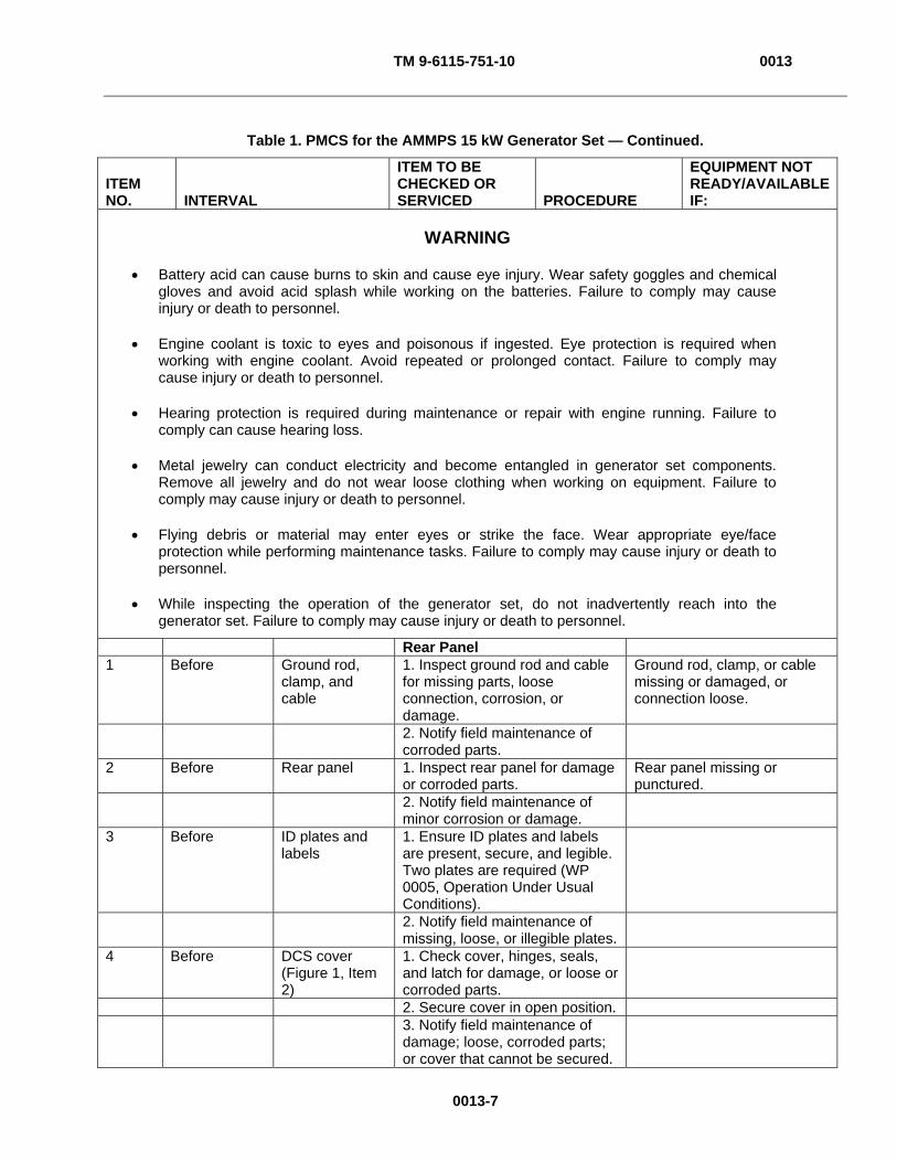
TM 9-6115-751-10 0013
0013-7
Table 1. PMCS for the AMMPS 15 kW Generator Set — Continued.
ITEM NO. INTERVAL
ITEM TO BE CHECKED OR SERVICED PROCEDURE
EQUIPMENT NOT READY/AVAILABLE IF:
WARNING
Battery acid can cause burns to skin and cause eye injury. Wear safety goggles and chemical gloves and avoid acid splash while working on the batteries. Failure to comply may cause injury or death to personnel.
Engine coolant is toxic to eyes and poisonous if ingested. Eye protection is required when working with engine coolant. Avoid repeated or prolonged contact. Failure to comply may cause injury or death to personnel.
Hearing protection is required during maintenance or repair with engine running. Failure to comply can cause hearing loss.
Metal jewelry can conduct electricity and become entangled in generator set components. Remove all jewelry and do not wear loose clothing when working on equipment. Failure to comply may cause injury or death to personnel.
Flying debris or material may enter eyes or strike the face. Wear appropriate eye/face protection while performing maintenance tasks. Failure to comply may cause injury or death to personnel.
While inspecting the operation of the generator set, do not inadvertently reach into the generator set. Failure to comply may cause injury or death to personnel.
Rear Panel 1 Before Ground rod,
clamp, and cable
1. Inspect ground rod and cable for missing parts, loose connection, corrosion, or damage.
Ground rod, clamp, or cable missing or damaged, or connection loose.
2. Notify field maintenance of corroded parts.
2 Before Rear panel 1. Inspect rear panel for damage or corroded parts.
Rear panel missing or punctured.
2. Notify field maintenance of minor corrosion or damage.
3 Before ID plates and labels
1. Ensure ID plates and labels are present, secure, and legible. Two plates are required (WP 0005, Operation Under Usual Conditions).
2. Notify field maintenance of missing, loose, or illegible plates.
4 Before DCS cover (Figure 1, Item 2)
1. Check cover, hinges, seals, and latch for damage, or loose or corroded parts.
2. Secure cover in open position. 3. Notify field maintenance of
damage; loose, corroded parts; or cover that cannot be secured.
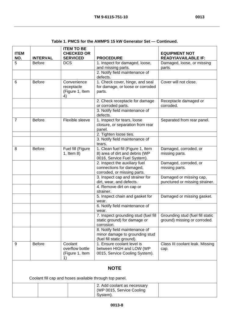
TM 9-6115-751-10 0013
0013-8
Table 1. PMCS for the AMMPS 15 kW Generator Set — Continued.
ITEM NO. INTERVAL
ITEM TO BE CHECKED OR SERVICED PROCEDURE
EQUIPMENT NOT READY/AVAILABLE IF:
5 Before DCS 1. Inspect for damaged, loose, and missing parts.
Damaged, loose, or missing parts.
2. Notify field maintenance of defects.
6 Before Convenience receptacle (Figure 1, Item 4)
1. Check cover, hinge, and seal for damage, or loose or corroded parts.
Cover will not close.
2. Check receptacle for damage or corroded parts.
Receptacle damaged or corroded.
3. Notify field maintenance of defects.
7 Before Flexible sleeve 1. Inspect for tears, loose closure, or separation from rear panel.
Separated from rear panel.
2. Tighten loose ties. 3. Notify field maintenance of
tears.
8 Before Fuel fill (Figure 1, Item 8)
1. Clean fuel fill (Figure 1, Item 8) area of dirt and debris (WP 0016, Service Fuel System).
Damaged, corroded, or missing parts.
2. Inspect the auxiliary fuel connections for damaged, corroded, or missing parts.
Damaged, corroded, or missing parts.
3. Inspect cap and strainer for dirt, wear, and defects.
Damaged or missing cap, punctured or missing strainer.
4. Remove dirt on cap or strainer.
5. Inspect chain and gasket for wear.
Damaged or missing gasket.
6. Notify field maintenance of wear.
7. Inspect grounding stud (fuel fill static ground) for damage or corrosion.
Grounding stud (fuel fill static ground) missing or corroded.
8. Notify field maintenance of minor damage to grounding stud (fuel fill static ground).
9 Before Coolant overflow bottle (Figure 1, Item 1)
1. Ensure coolant level is between HIGH and LOW (WP 0015, Service Cooling System).
Class III coolant leak. Missing cap.
NOTE
Coolant fill cap and hoses available through top panel.
2. Add coolant as necessary (WP 0015, Service Cooling System).
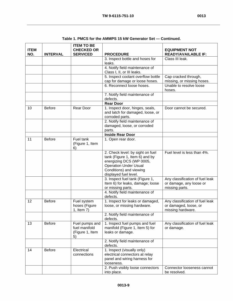
TM 9-6115-751-10 0013
0013-9
Table 1. PMCS for the AMMPS 15 kW Generator Set — Continued.
ITEM NO. INTERVAL
ITEM TO BE CHECKED OR SERVICED PROCEDURE
EQUIPMENT NOT READY/AVAILABLE IF:
3. Inspect bottle and hoses for leaks.
Class III leak.
4. Notify field maintenance of Class I, II, or III leaks.
5. Inspect coolant overflow bottle cap for damage or loose hoses.
Cap cracked through, missing, or missing hoses.
6. Reconnect loose hoses. Unable to resolve loose hoses.
7. Notify field maintenance of defects.
Rear Door 10 Before Rear Door 1. Inspect door, hinges, seals,
and latch for damaged, loose, or corroded parts.
Door cannot be secured.
2. Notify field maintenance of damaged, loose, or corroded parts.
Inside Rear Door 11 Before Fuel tank
(Figure 1, Item 6)
1. Open rear door.
2. Check level: by sight on fuel tank (Figure 1, Item 6) and by energizing DCS (WP 0005, Operation Under Usual Conditions) and viewing displayed fuel level.
Fuel level is less than 4%.
3. Inspect fuel tank (Figure 1, Item 6) for leaks, damage; loose or missing parts.
Any classification of fuel leak or damage, any loose or missing parts.
4. Notify field maintenance of defects.
12 Before Fuel system hoses (Figure 1, Item 7)
1. Inspect for leaks or damaged, loose, or missing hardware.
Any classification of fuel leak or damaged, loose, or missing hardware.
2. Notify field maintenance of defects.
13 Before Fuel pumps and fuel manifold (Figure 1, Item 5)
1. Inspect fuel pumps and fuel manifold (Figure 1, Item 5) for leaks or damage.
Any classification of fuel leak or damage.
2. Notify field maintenance of defects.
14 Before Electrical connections
1. Inspect (visually only) electrical connectors at relay panel and wiring harness for looseness.
2. Push visibly loose connectors into place.
Connector looseness cannot be resolved.
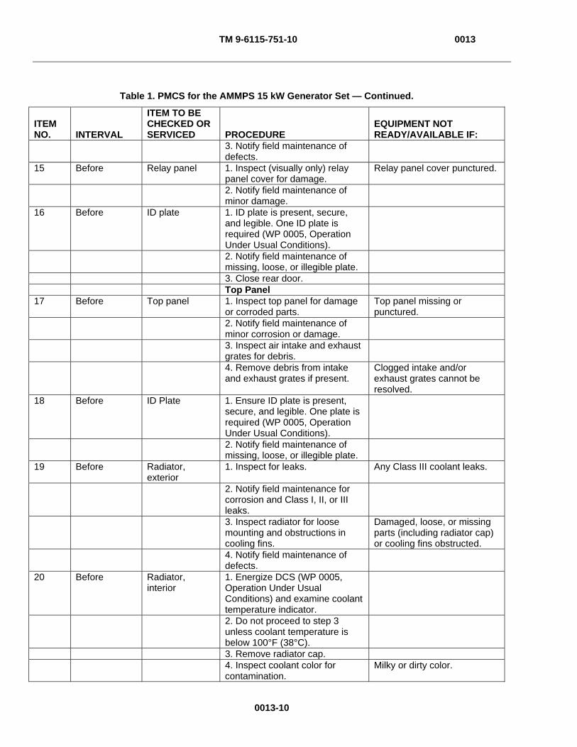
TM 9-6115-751-10 0013
0013-10
Table 1. PMCS for the AMMPS 15 kW Generator Set — Continued.
ITEM NO. INTERVAL
ITEM TO BE CHECKED OR SERVICED PROCEDURE
EQUIPMENT NOT READY/AVAILABLE IF:
3. Notify field maintenance of defects.
15 Before Relay panel 1. Inspect (visually only) relay panel cover for damage.
Relay panel cover punctured.
2. Notify field maintenance of minor damage.
16 Before ID plate 1. ID plate is present, secure, and legible. One ID plate is required (WP 0005, Operation Under Usual Conditions).
2. Notify field maintenance of missing, loose, or illegible plate.
3. Close rear door. Top Panel 17 Before Top panel 1. Inspect top panel for damage
or corroded parts. Top panel missing or punctured.
2. Notify field maintenance of minor corrosion or damage.
3. Inspect air intake and exhaust grates for debris.
4. Remove debris from intake and exhaust grates if present.
Clogged intake and/or exhaust grates cannot be resolved.
18 Before ID Plate 1. Ensure ID plate is present, secure, and legible. One plate is required (WP 0005, Operation Under Usual Conditions).
2. Notify field maintenance of missing, loose, or illegible plate.
19 Before Radiator, exterior
1. Inspect for leaks. Any Class III coolant leaks.
2. Notify field maintenance for corrosion and Class I, II, or III leaks.
3. Inspect radiator for loose mounting and obstructions in cooling fins.
Damaged, loose, or missing parts (including radiator cap) or cooling fins obstructed.
4. Notify field maintenance of defects.
20 Before Radiator, interior
1. Energize DCS (WP 0005, Operation Under Usual Conditions) and examine coolant temperature indicator.
2. Do not proceed to step 3 unless coolant temperature is below 100°F (38°C).
3. Remove radiator cap. 4. Inspect coolant color for
contamination. Milky or dirty color.
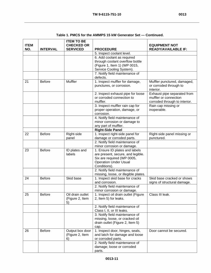
TM 9-6115-751-10 0013
0013-11
Table 1. PMCS for the AMMPS 15 kW Generator Set — Continued.
ITEM NO. INTERVAL
ITEM TO BE CHECKED OR SERVICED PROCEDURE
EQUIPMENT NOT READY/AVAILABLE IF:
5. Inspect coolant level. 6. Add coolant as required
through coolant overflow bottle (Figure 1, Item 1) (WP 0015, Service Cooling System).
7. Notify field maintenance of defects.
21 Before Muffler 1. Inspect muffler for damage, punctures, or corrosion.
Muffler punctured, damaged, or corroded through to interior.
2. Inspect exhaust pipe for loose or corroded connection to muffler.
Exhaust pipe separated from muffler or connection corroded through to interior.
3. Inspect muffler rain cap for proper operation, damage, or corrosion.
Rain cap missing or inoperable.
4. Notify field maintenance of minor corrosion or damage to any part of muffler.
Right-Side Panel 22 Before Right-side
panel 1. Inspect right-side panel for damage or corroded parts.
Right-side panel missing or punctured.
2. Notify field maintenance of minor corrosion or damage.
23 Before ID plates and labels
1. Ensure ID plates and labels are present, secure, and legible. Six are required (WP 0005, Operation Under Usual Conditions).
2. Notify field maintenance of missing, loose, or illegible plates.
24 Before Skid base 1. Inspect skid base for cracks and corrosion.
Skid base cracked or shows signs of structural damage.
2. Notify field maintenance of minor corrosion or damage.
25 Before Oil drain outlet (Figure 2, Item 5)
1. Inspect oil drain outlet (Figure 2, Item 5) for leaks.
Class III leak.
2. Notify field maintenance of Class I, II, or III leaks.
3. Notify field maintenance of missing, loose, or cracked oil drain outlet (Figure 2, Item 5) cap.
26 Before Output box door (Figure 2, Item 6)
1. Inspect door, hinges, seals, and latch for damage and loose or corroded parts.
Door cannot be secured.
2. Notify field maintenance of damage; loose or corroded parts.

TM 9-6115-751-10 0013
0013-12
Table 1. PMCS for the AMMPS 15 kW Generator Set — Continued.
ITEM NO. INTERVAL
ITEM TO BE CHECKED OR SERVICED PROCEDURE
EQUIPMENT NOT READY/AVAILABLE IF:
27 Before Right-side door 1. Inspect door, hinges, seals, and latch for damage; loose or corroded parts.
Door cannot be secured.
2. Notify field maintenance of damage; loose or corroded parts.
Inside Output Box Door 28 Before Output
connections 1. Open output box door (Figure 2, Item 6).
2. Inspect ground and load cable connections for tightness to output load board by pulling gently.
3. Tighten as required (WP 0005, Operation Under Usual Conditions).
Cable cannot be secured.
4. Inspect terminals and terminal nuts for damage or corrosion.
5. Notify field maintenance of damage or corrosion to terminals or terminal nuts.
29 Before Output terminal board protective cover
1. Inspect output terminal board protective cover for cracks, corroded hinge, or damage.
Output terminal board protective cover missing or punctured, damaged or missing hinge or hinge fasteners.
2. Notify field maintenance of corroded hinge or minor damage.
30 Before ID plates 1. Ensure ID plates are present, secure, and legible. Two are required (WP 0005, Operation Under Usual Conditions).
2. Notify field maintenance of missing, loose, or illegible plates.
31 Before Terminal nut wrench
1. Inspect for damage.
2. Notify field maintenance of damage or missing terminal nut wrench.
3. Close Output box door (Figure 2, Item 6).
Inside Right-Side Door 32 Before Engine and
compartment base
1. Open right-side door.
2. Inspect for leaks. Any classification of fuel leak. Class III oil or coolant leaks.
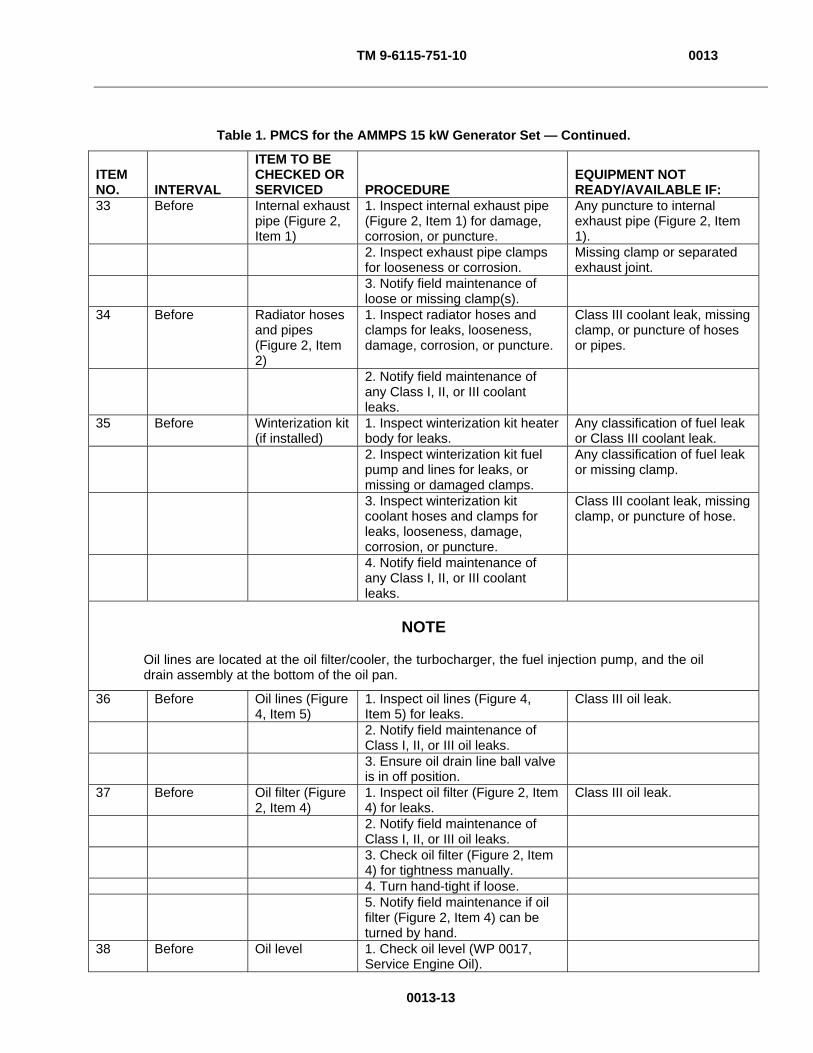
TM 9-6115-751-10 0013
0013-13
Table 1. PMCS for the AMMPS 15 kW Generator Set — Continued.
ITEM NO. INTERVAL
ITEM TO BE CHECKED OR SERVICED PROCEDURE
EQUIPMENT NOT READY/AVAILABLE IF:
33 Before Internal exhaust pipe (Figure 2, Item 1)
1. Inspect internal exhaust pipe (Figure 2, Item 1) for damage, corrosion, or puncture.
Any puncture to internal exhaust pipe (Figure 2, Item 1).
2. Inspect exhaust pipe clamps for looseness or corrosion.
Missing clamp or separated exhaust joint.
3. Notify field maintenance of loose or missing clamp(s).
34 Before Radiator hoses and pipes (Figure 2, Item 2)
1. Inspect radiator hoses and clamps for leaks, looseness, damage, corrosion, or puncture.
Class III coolant leak, missing clamp, or puncture of hoses or pipes.
2. Notify field maintenance of any Class I, II, or III coolant leaks.
35 Before Winterization kit (if installed)
1. Inspect winterization kit heater body for leaks.
Any classification of fuel leak or Class III coolant leak.
2. Inspect winterization kit fuel pump and lines for leaks, or missing or damaged clamps.
Any classification of fuel leak or missing clamp.
3. Inspect winterization kit coolant hoses and clamps for leaks, looseness, damage, corrosion, or puncture.
Class III coolant leak, missing clamp, or puncture of hose.
4. Notify field maintenance of any Class I, II, or III coolant leaks.
NOTE
Oil lines are located at the oil filter/cooler, the turbocharger, the fuel injection pump, and the oil drain assembly at the bottom of the oil pan.
36 Before Oil lines (Figure 4, Item 5)
1. Inspect oil lines (Figure 4, Item 5) for leaks.
Class III oil leak.
2. Notify field maintenance of Class I, II, or III oil leaks.
3. Ensure oil drain line ball valve is in off position.
37 Before Oil filter (Figure 2, Item 4)
1. Inspect oil filter (Figure 2, Item 4) for leaks.
Class III oil leak.
2. Notify field maintenance of Class I, II, or III oil leaks.
3. Check oil filter (Figure 2, Item 4) for tightness manually.
4. Turn hand-tight if loose. 5. Notify field maintenance if oil
filter (Figure 2, Item 4) can be turned by hand.
38 Before Oil level 1. Check oil level (WP 0017, Service Engine Oil).
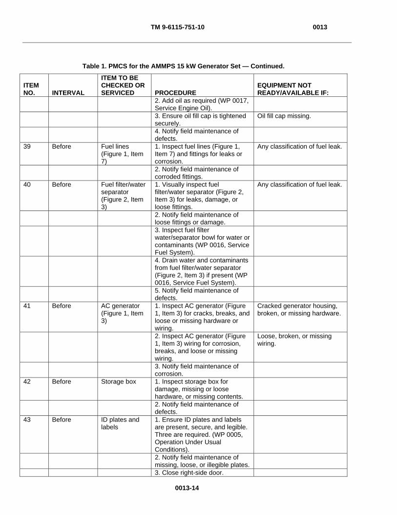
TM 9-6115-751-10 0013
0013-14
Table 1. PMCS for the AMMPS 15 kW Generator Set — Continued.
ITEM NO. INTERVAL
ITEM TO BE CHECKED OR SERVICED PROCEDURE
EQUIPMENT NOT READY/AVAILABLE IF:
2. Add oil as required (WP 0017, Service Engine Oil).
3. Ensure oil fill cap is tightened securely.
Oil fill cap missing.
4. Notify field maintenance of defects.
39 Before Fuel lines (Figure 1, Item 7)
1. Inspect fuel lines (Figure 1, Item 7) and fittings for leaks or corrosion.
Any classification of fuel leak.
2. Notify field maintenance of corroded fittings.
40 Before Fuel filter/water separator (Figure 2, Item 3)
1. Visually inspect fuel filter/water separator (Figure 2, Item 3) for leaks, damage, or loose fittings.
Any classification of fuel leak.
2. Notify field maintenance of loose fittings or damage.
3. Inspect fuel filter water/separator bowl for water or contaminants (WP 0016, Service Fuel System).
4. Drain water and contaminants from fuel filter/water separator (Figure 2, Item 3) if present (WP 0016, Service Fuel System).
5. Notify field maintenance of defects.
41 Before AC generator (Figure 1, Item 3)
1. Inspect AC generator (Figure 1, Item 3) for cracks, breaks, and loose or missing hardware or wiring.
Cracked generator housing, broken, or missing hardware.
2. Inspect AC generator (Figure 1, Item 3) wiring for corrosion, breaks, and loose or missing wiring.
Loose, broken, or missing wiring.
3. Notify field maintenance of corrosion.
42 Before Storage box 1. Inspect storage box for damage, missing or loose hardware, or missing contents.
2. Notify field maintenance of defects.
43 Before ID plates and labels
1. Ensure ID plates and labels are present, secure, and legible. Three are required. (WP 0005, Operation Under Usual Conditions).
2. Notify field maintenance of missing, loose, or illegible plates.
3. Close right-side door.
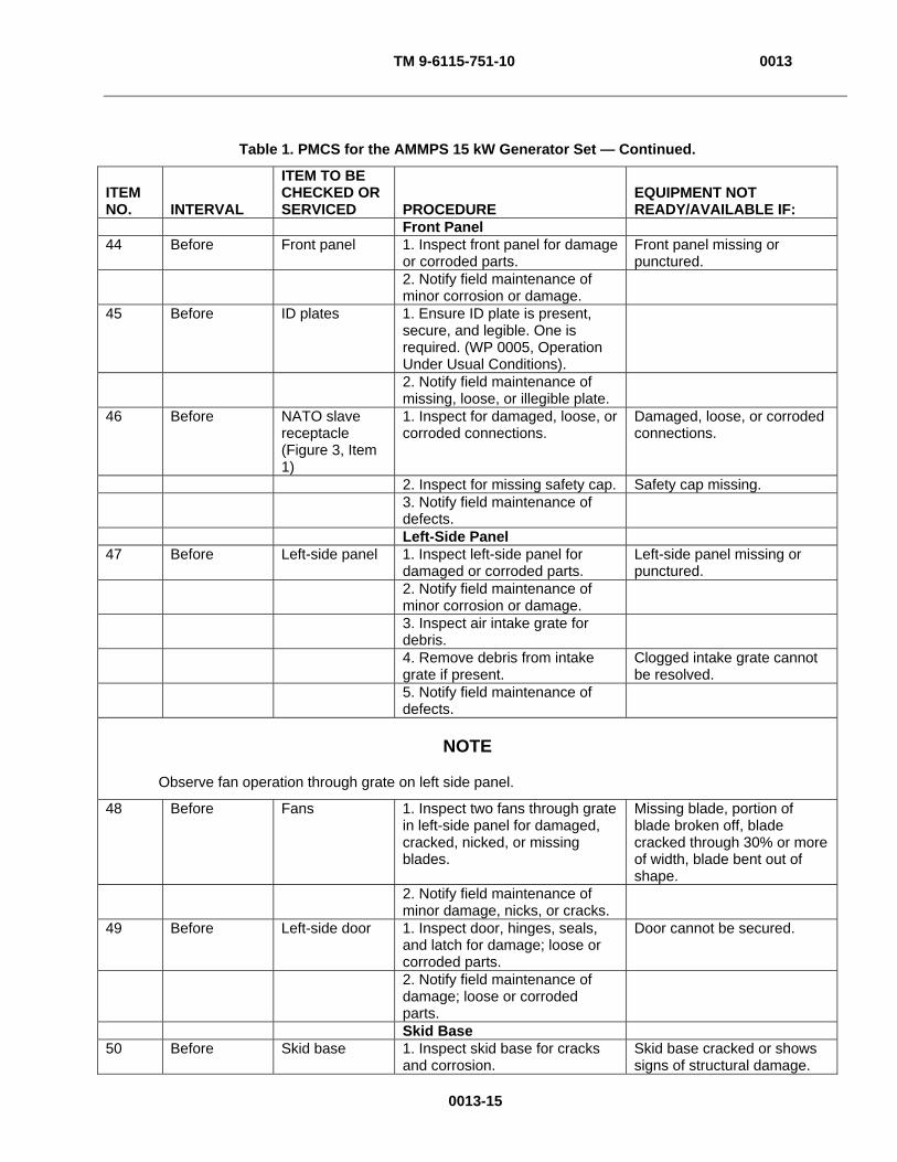
TM 9-6115-751-10 0013
0013-15
Table 1. PMCS for the AMMPS 15 kW Generator Set — Continued.
ITEM NO. INTERVAL
ITEM TO BE CHECKED OR SERVICED PROCEDURE
EQUIPMENT NOT READY/AVAILABLE IF:
Front Panel 44 Before Front panel 1. Inspect front panel for damage
or corroded parts. Front panel missing or punctured.
2. Notify field maintenance of minor corrosion or damage.
45 Before ID plates 1. Ensure ID plate is present, secure, and legible. One is required. (WP 0005, Operation Under Usual Conditions).
2. Notify field maintenance of missing, loose, or illegible plate.
46 Before NATO slave receptacle (Figure 3, Item 1)
1. Inspect for damaged, loose, or corroded connections.
Damaged, loose, or corroded connections.
2. Inspect for missing safety cap. Safety cap missing. 3. Notify field maintenance of
defects.
Left-Side Panel 47 Before Left-side panel 1. Inspect left-side panel for
damaged or corroded parts. Left-side panel missing or punctured.
2. Notify field maintenance of minor corrosion or damage.
3. Inspect air intake grate for debris.
4. Remove debris from intake grate if present.
Clogged intake grate cannot be resolved.
5. Notify field maintenance of defects.
NOTE
Observe fan operation through grate on left side panel.
48 Before Fans 1. Inspect two fans through grate in left-side panel for damaged, cracked, nicked, or missing blades.
Missing blade, portion of blade broken off, blade cracked through 30% or more of width, blade bent out of shape.
2. Notify field maintenance of minor damage, nicks, or cracks.
49 Before Left-side door 1. Inspect door, hinges, seals, and latch for damage; loose or corroded parts.
Door cannot be secured.
2. Notify field maintenance of damage; loose or corroded parts.
Skid Base 50 Before Skid base 1. Inspect skid base for cracks
and corrosion. Skid base cracked or shows signs of structural damage.

TM 9-6115-751-10 0013
0013-16
Table 1. PMCS for the AMMPS 15 kW Generator Set — Continued.
ITEM NO. INTERVAL
ITEM TO BE CHECKED OR SERVICED PROCEDURE
EQUIPMENT NOT READY/AVAILABLE IF:
2. Notify field maintenance of minor corrosion or damage.
51 Before Fuel drain line 1. Inspect for leaks, damage, corrosion, or missing cap (located at rear of skid base).
Any leaks or missing cap.
2. Notify field maintenance of damage or corroded parts.
52 Before Fuel drain valve 1. Ensure fuel drain valve is in off position (valve handle perpendicular to line).
2. Inspect for leaks, damage, or corroded parts.
Any leaks.
3. Notify field maintenance of damage or corroded parts.
Inside Left-Side Door 53 Before Engine and
compartment base
1. Open left-side door.
2. Inspect for leaks. Any classification of fuel leak. Class III oil or coolant leaks.
3. Notify field maintenance of any Class I, II, or III oil or coolant leaks.
54 Before Battery-charging alternator (Figure 4, Item 1)
1. Inspect for loose wires or cracked housing.
Loose wires or cracked housing.
2. Inspect battery-charging alternator (Figure 4, Item 1) belt for presence, looseness, frays, or cracks.
Belt missing, loose, frayed, or cracked.
3. Notify field maintenance of corroded terminals, loose connections, or missing plastic terminal covers.
55 Before Batteries (Figure 4, Item 4) and cables
1. Inspect batteries (Figure 4, Item 4) for swollen or cracked casings, corroded terminals, loose or corroded cables and connections.
Cracked or swollen casing, disconnected cable, loose cable that can be removed by hand.
2. Notify field maintenance of corroded or loose terminals or cables.
56 Before Starter (Figure 4, Item 3)
1. Inspect starter (Figure 4, Item 3) for damage, corrosion, or loose wiring.
2. Notify field maintenance of damage, corrosion, or loose connections or wires.
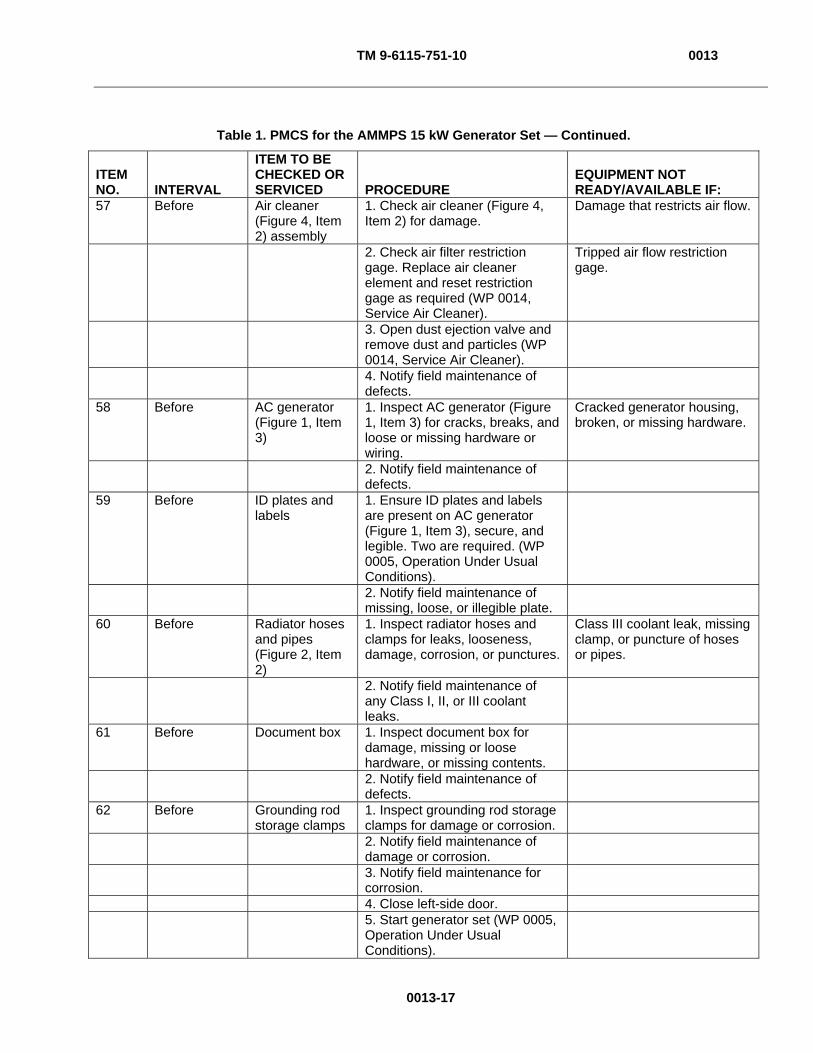
TM 9-6115-751-10 0013
0013-17
Table 1. PMCS for the AMMPS 15 kW Generator Set — Continued.
ITEM NO. INTERVAL
ITEM TO BE CHECKED OR SERVICED PROCEDURE
EQUIPMENT NOT READY/AVAILABLE IF:
57 Before Air cleaner (Figure 4, Item 2) assembly
1. Check air cleaner (Figure 4, Item 2) for damage.
Damage that restricts air flow.
2. Check air filter restriction gage. Replace air cleaner element and reset restriction gage as required (WP 0014, Service Air Cleaner).
Tripped air flow restriction gage.
3. Open dust ejection valve and remove dust and particles (WP 0014, Service Air Cleaner).
4. Notify field maintenance of defects.
58 Before AC generator (Figure 1, Item 3)
1. Inspect AC generator (Figure 1, Item 3) for cracks, breaks, and loose or missing hardware or wiring.
Cracked generator housing, broken, or missing hardware.
2. Notify field maintenance of defects.
59 Before ID plates and labels
1. Ensure ID plates and labels are present on AC generator (Figure 1, Item 3), secure, and legible. Two are required. (WP 0005, Operation Under Usual Conditions).
2. Notify field maintenance of missing, loose, or illegible plate.
60 Before Radiator hoses and pipes (Figure 2, Item 2)
1. Inspect radiator hoses and clamps for leaks, looseness, damage, corrosion, or punctures.
Class III coolant leak, missing clamp, or puncture of hoses or pipes.
2. Notify field maintenance of any Class I, II, or III coolant leaks.
61 Before Document box 1. Inspect document box for damage, missing or loose hardware, or missing contents.
2. Notify field maintenance of defects.
62 Before Grounding rod storage clamps
1. Inspect grounding rod storage clamps for damage or corrosion.
2. Notify field maintenance of damage or corrosion.
3. Notify field maintenance for corrosion.
4. Close left-side door. 5. Start generator set (WP 0005,
Operation Under Usual Conditions).

TM 9-6115-751-10 0013
0013-18
Table 1. PMCS for the AMMPS 15 kW Generator Set — Continued.
ITEM NO. INTERVAL
ITEM TO BE CHECKED OR SERVICED PROCEDURE
EQUIPMENT NOT READY/AVAILABLE IF:
Rear Panel and Inside Rear Door
During 63 During DCS 1. Inspect main screen indicators
for proper operation, erratic display, obvious improper reporting (example: unit overheated, coolant temperature indicates 150°F (65.5°C)) (WP 0005, Operation Under Usual Conditions).
Indicators not operating properly.
2. Check battery voltage on DCS operator’s main screen (WP 0005, Operation Under Usual Conditions).
Battery voltage is below 16 VDC.
3. Ensure circuit interrupter is closed as required.
4. Close as required. Circuit interrupter will not remain closed.
5. Notify field maintenance of defects.
NOTE
Coolant fill cap and hoses available through top panel.
64 During Coolant overflow bottle (Figure 1, Item 1)
1. Inspect for leaks or loose hoses.
Class III coolant leak or missing cap.
2. Check coolant level (WP 0015, Service Cooling System).
3. Notify field maintenance of defects.
65 During Convenience receptacle (Figure 1, Item 4)
1. Reset GFCI circuit breaker after [Contactor Closed] has appeared on DCS (WP 0005, Operation Under Usual Conditions).
2. Notify field maintenance of defects.
66 During Engine 1. Check color of exhaust smoke.
Exhaust smoke is black, white, or blue.
2. Listen for any unusual engine noises.
Unusual, severe engine noises.
3. Notify field maintenance of defects.
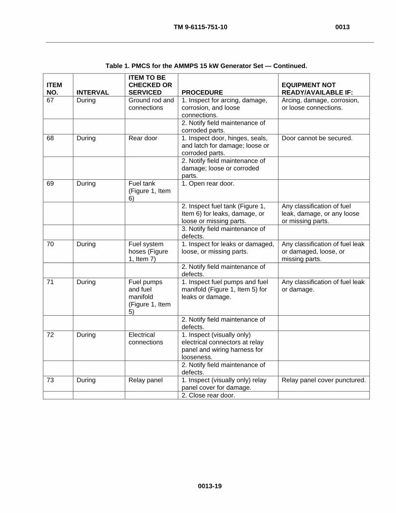
TM 9-6115-751-10 0013
0013-19
Table 1. PMCS for the AMMPS 15 kW Generator Set — Continued.
ITEM NO. INTERVAL
ITEM TO BE CHECKED OR SERVICED PROCEDURE
EQUIPMENT NOT READY/AVAILABLE IF:
67 During Ground rod and connections
1. Inspect for arcing, damage, corrosion, and loose connections.
Arcing, damage, corrosion, or loose connections.
2. Notify field maintenance of corroded parts.
68 During Rear door 1. Inspect door, hinges, seals, and latch for damage; loose or corroded parts.
Door cannot be secured.
2. Notify field maintenance of damage; loose or corroded parts.
69 During Fuel tank (Figure 1, Item 6)
1. Open rear door.
2. Inspect fuel tank (Figure 1, Item 6) for leaks, damage, or loose or missing parts.
Any classification of fuel leak, damage, or any loose or missing parts.
3. Notify field maintenance of defects.
70 During Fuel system hoses (Figure 1, Item 7)
1. Inspect for leaks or damaged, loose, or missing parts.
Any classification of fuel leak or damaged, loose, or missing parts.
2. Notify field maintenance of defects.
71 During Fuel pumps and fuel manifold (Figure 1, Item 5)
1. Inspect fuel pumps and fuel manifold (Figure 1, Item 5) for leaks or damage.
Any classification of fuel leak or damage.
2. Notify field maintenance of defects.
72 During Electrical connections
1. Inspect (visually only) electrical connectors at relay panel and wiring harness for looseness.
2. Notify field maintenance of defects.
73 During Relay panel 1. Inspect (visually only) relay panel cover for damage.
Relay panel cover punctured.
2. Close rear door.

TM 9-6115-751-10 0013
0013-20
Table 1. PMCS for the AMMPS 15 kW Generator Set — Continued.
ITEM NO. INTERVAL
ITEM TO BE CHECKED OR SERVICED PROCEDURE
EQUIPMENT NOT READY/AVAILABLE IF:
Inside Right-Side Door
CAUTION
Operating generator set with doors open or with panels removed for an extended length of time will cause engine to overheat. Do not operate generator with doors open or panels removed for longer than necessary to complete your task. Monitor DCS temperature indicator to prevent engine overheating. Failure to comply will cause damage to equipment.
74 During Engine and compartment base
1. Open right-side door.
2. Inspect for leaks. Any classification of fuel leak.
Class III oil or coolant leaks.
3. Notify field maintenance of any Class I, II, or III oil or coolant leaks.
NOTE
Oil lines are located at the oil filter/cooler, the turbocharger, the fuel injection pump, and the oil drain assembly at the bottom of the oil pan.
75 During Oil lines (Figure 4, Item 5)
1. Inspect oil lines (Figure 4, Item 5) for leaks.
Class III oil leak.
2. Notify field maintenance of Class I, II, or III oil leaks.
76 During Fuel lines (Figure 1, Item 7) and fuel filter/water separator (Figure 2, Item 3)
1. Inspect fuel lines (Figure 1, Item 7), fittings, and fuel filter/water separator (Figure 2, Item 3) for leaks or corrosion.
Any classification of fuel leak.
2. Notify field maintenance of defects.
NOTE
Check engine oil level each time the fuel tank (Figure 1, Item 6) is filled or once every 8 hr when operating continuous operation utilizing an auxiliary fuel source.
77 During Oil level 1. Check oil level (WP 0017, Service Engine Oil).
2. Add oil as required (WP 0017, Service Engine Oil).
3. Ensure oil fill cap is tightened securely.
Oil fill cap missing.
4. Notify field maintenance of defects.
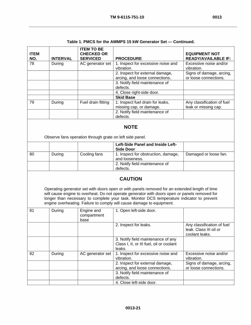
TM 9-6115-751-10 0013
0013-21
Table 1. PMCS for the AMMPS 15 kW Generator Set — Continued.
ITEM NO. INTERVAL
ITEM TO BE CHECKED OR SERVICED PROCEDURE
EQUIPMENT NOT READY/AVAILABLE IF:
78 During AC generator set 1. Inspect for excessive noise and vibration.
Excessive noise and/or vibration.
2. Inspect for external damage, arcing, and loose connections.
Signs of damage, arcing, or loose connections.
3. Notify field maintenance of defects.
4. Close right-side door. Skid Base 79 During Fuel drain fitting 1. Inspect fuel drain for leaks,
missing cap, or damage. Any classification of fuel leak or missing cap.
2. Notify field maintenance of defects.
NOTE
Observe fans operation through grate on left side panel.
Left-Side Panel and Inside Left-Side Door
80 During Cooling fans 1. Inspect for obstruction, damage, and looseness.
Damaged or loose fan.
2. Notify field maintenance of defects.
CAUTION
Operating generator set with doors open or with panels removed for an extended length of time will cause engine to overheat. Do not operate generator with doors open or panels removed for longer than necessary to complete your task. Monitor DCS temperature indicator to prevent engine overheating. Failure to comply will cause damage to equipment.
81 During Engine and compartment base
1. Open left-side door.
2. Inspect for leaks. Any classification of fuel leak. Class III oil or coolant leaks.
3. Notify field maintenance of any Class I, II, or III fuel, oil or coolant leaks.
82 During AC generator set 1. Inspect for excessive noise and vibration.
Excessive noise and/or vibration.
2. Inspect for external damage, arcing, and loose connections.
Signs of damage, arcing, or loose connections.
3. Notify field maintenance of defects.
4. Close left-side door.

TM 9-6115-751-10 0013
0013-22
Table 1. PMCS for the AMMPS 15 kW Generator Set — Continued.
ITEM NO. INTERVAL
ITEM TO BE CHECKED OR SERVICED PROCEDURE
EQUIPMENT NOT READY/AVAILABLE IF:
NOTE
Allow generator set to cool for 15 min before performing after operation PMCS. Perform after operation PMCS in the sequence indicated, beginning at the rear panel and proceeding counterclockwise to the left-side panel.
After 83 After Fuel fill (Figure
1, Item 8) 1. Clean fuel fill (Figure 1, Item 8) area of dirt and debris (WP 0016, Service Fuel System).
2. Inspect the auxiliary fuel connections for damaged, corroded, or missing parts.
Damaged, corroded, or missing parts.
3. Inspect cap and strainer for dirt, wear, and defects.
Damaged or missing cap. Punctured or missing strainer.
4. Inspect chain and gasket for wear.
Damaged or missing gasket.
5. Inspect grounding stud (fuel fill static ground) for damage or corrosion.
Grounding stud (fuel fill static ground) missing or corroded.
6. Notify field maintenance of defects.
84 After Fuel tank (Figure 1, Item 6)
1. Refill fuel tank (Figure 1, Item 6) to capacity (WP 0016, Service Fuel System).
2. Notify field maintenance of defects.
85 After Coolant overflow bottle (Figure 1, Item 1).
1. Inspect for leaks, cracks, loose hoses, or missing cap.
Class III coolant leak. Missing cap.
2. Connect loose hoses. Hose cannot be reconnected. 3. Check coolant level (WP
0015, Service Cooling System).
4. Fill cooling system as required (WP 0015, Service Cooling System).
5. Notify field maintenance of defects.
86 After Output connections
1. Inspect ground and load cable connections for tightness to output load board by pulling gently.
2. Tighten as required (WP 0005, Operation Under Usual Conditions).
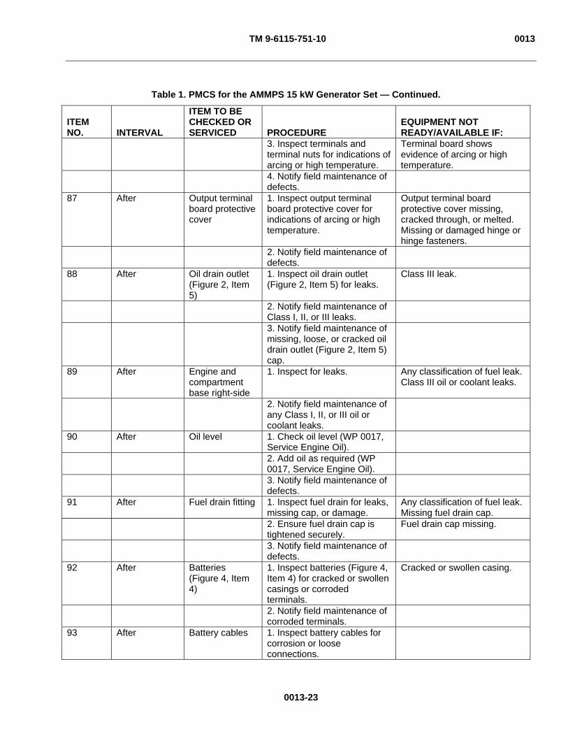
TM 9-6115-751-10 0013
0013-23
Table 1. PMCS for the AMMPS 15 kW Generator Set — Continued.
ITEM NO. INTERVAL
ITEM TO BE CHECKED OR SERVICED PROCEDURE
EQUIPMENT NOT READY/AVAILABLE IF:
3. Inspect terminals and terminal nuts for indications of arcing or high temperature.
Terminal board shows evidence of arcing or high temperature.
4. Notify field maintenance of defects.
87 After Output terminal board protective cover
1. Inspect output terminal board protective cover for indications of arcing or high temperature.
Output terminal board protective cover missing, cracked through, or melted. Missing or damaged hinge or hinge fasteners.
2. Notify field maintenance of defects.
88 After Oil drain outlet (Figure 2, Item 5)
1. Inspect oil drain outlet (Figure 2, Item 5) for leaks.
Class III leak.
2. Notify field maintenance of Class I, II, or III leaks.
3. Notify field maintenance of missing, loose, or cracked oil drain outlet (Figure 2, Item 5) cap.
89 After Engine and compartment base right-side
1. Inspect for leaks. Any classification of fuel leak. Class III oil or coolant leaks.
2. Notify field maintenance of any Class I, II, or III oil or coolant leaks.
90 After Oil level 1. Check oil level (WP 0017, Service Engine Oil).
2. Add oil as required (WP 0017, Service Engine Oil).
3. Notify field maintenance of defects.
91 After Fuel drain fitting 1. Inspect fuel drain for leaks, missing cap, or damage.
Any classification of fuel leak. Missing fuel drain cap.
2. Ensure fuel drain cap is tightened securely.
Fuel drain cap missing.
3. Notify field maintenance of defects.
92 After Batteries (Figure 4, Item 4)
1. Inspect batteries (Figure 4, Item 4) for cracked or swollen casings or corroded terminals.
Cracked or swollen casing.
2. Notify field maintenance of corroded terminals.
93 After Battery cables 1. Inspect battery cables for corrosion or loose connections.

TM 9-6115-751-10 0013
0013-24
Table 1. PMCS for the AMMPS 15 kW Generator Set — Continued.
ITEM NO. INTERVAL
ITEM TO BE CHECKED OR SERVICED PROCEDURE
EQUIPMENT NOT READY/AVAILABLE IF:
2. Notify field maintenance of corroded or loose connections.
94 After Engine and compartment base, left side.
1. Inspect for leaks. Any classification of fuel leak. Class III oil or coolant leaks.
2. Notify field maintenance of any Class I, II, or III oil or coolant leaks.
95 After Intake and exhaust grates
1. Clean debris from all intake and exhaust grates.
2. Notify field maintenance of defects.
96 After Radiator, interior
1. Energize DCS (WP 0005, Operation Under Usual Conditions) and examine coolant temperature indicator.
2. Do not proceed to step 3 until coolant temperature is below 100°F (38°C).
3. Remove radiator cap. 4. Inspect coolant color for
contamination. Milky or dirty color.
5. Inspect coolant level and add as required (WP 0015, Service Cooling System).
6. Notify field maintenance of defects.
END OF WORK PACKAGE

TM 9-6115-751-10 0014
OPERATOR MAINTENANCE
AMMPS 15KW GENERATOR SET
SERVICE AIR CLEANER
INITIAL SETUP:
Test Equipment
Not Applicable
Tools and Special Tools
Not Applicable
Materials/Parts
Element, air cleaner filter (WP 0021, Expendable and Durable Items List, Item 2)
Personnel Required
Operator (1)
References
Not Applicable
Equipment Conditions
Engine control switch OFF (WP 0005, Operation Under Usual Conditions)
Unit cool
SERVICE AIR CLEANER
Inspect Air Filter Restriction Indicator
Figure 1. Air Cleaner — Location.
0014-1
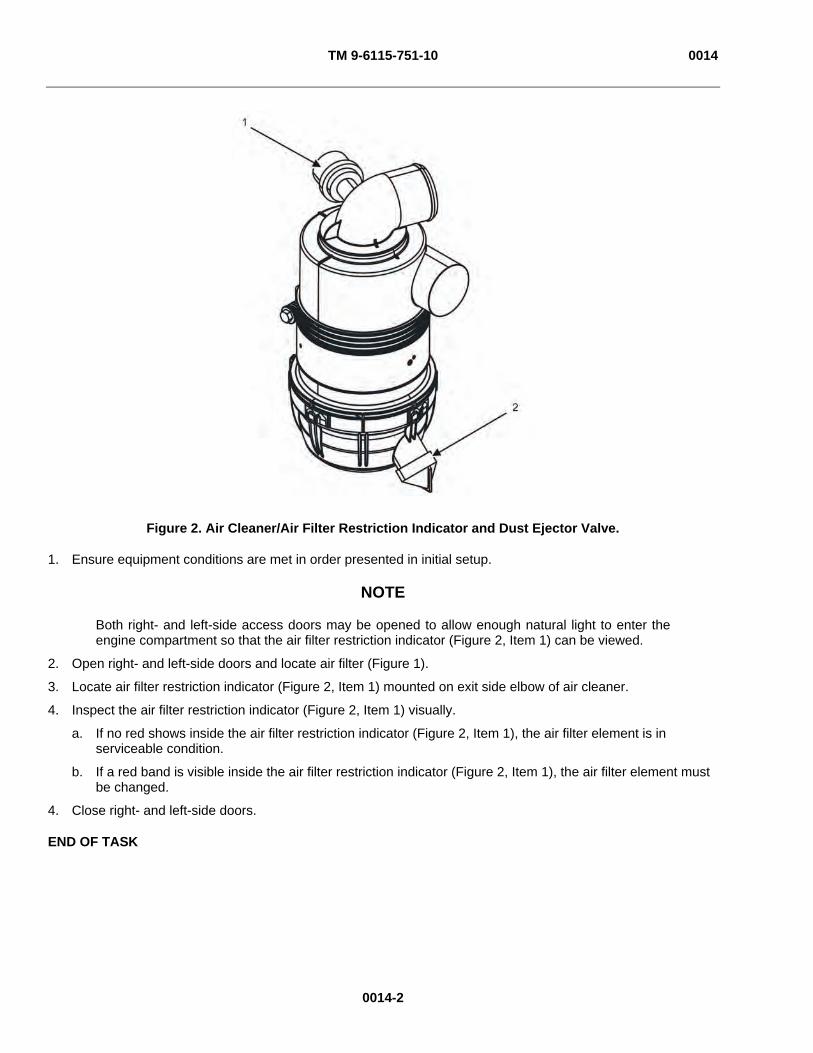
TM 9-6115-751-10 0014
Figure 2. Air Cleaner/Air Filter Restriction Indicator and Dust Ejector Valve.
1. Ensure equipment conditions are met in order presented in initial setup.
NOTE
Both right- and left-side access doors may be opened to allow enough natural light to enter the engine compartment so that the air filter restriction indicator (Figure 2, Item 1) can be viewed.
2. Open right- and left-side doors and locate air filter (Figure 1).
3. Locate air filter restriction indicator (Figure 2, Item 1) mounted on exit side elbow of air cleaner.
4. Inspect the air filter restriction indicator (Figure 2, Item 1) visually.
a. If no red shows inside the air filter restriction indicator (Figure 2, Item 1), the air filter element is in serviceable condition.
b. If a red band is visible inside the air filter restriction indicator (Figure 2, Item 1), the air filter element must be changed.
4. Close right- and left-side doors.
END OF TASK
0014-2
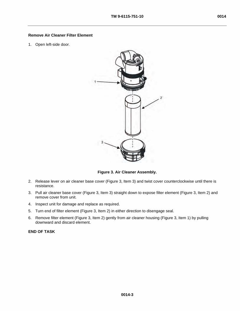
TM 9-6115-751-10 0014
Remove Air Cleaner Filter Element
1. Open left-side door.
Figure 3. Air Cleaner Assembly.
2. Release lever on air cleaner base cover (Figure 3, Item 3) and twist cover counterclockwise until there is resistance.
3. Pull air cleaner base cover (Figure 3, Item 3) straight down to expose filter element (Figure 3, Item 2) and remove cover from unit.
4. Inspect unit for damage and replace as required.
5. Turn end of filter element (Figure 3, Item 2) in either direction to disengage seal.
6. Remove filter element (Figure 3, Item 2) gently from air cleaner housing (Figure 3, Item 1) by pulling downward and discard element.
END OF TASK
0014-3

TM 9-6115-751-10 0014
0014-4
Install Air Cleaner Filter Element
1. Remove dirt and debris from air cleaner base cover (Figure 3, Item 3), sealing surfaces, and inside of air cleaner housing (Figure 3, Item 1).
2. Insert new filter element (Figure 3, Item 2) into air cleaner housing (Figure 3, Item 1) and twist in either direction to secure.
NOTE
When air cleaner base cover (Figure 3, Item 3) is placed on bottom of air cleaner and turned clockwise, a click can be heard when the cover is properly secured.
3. Position air cleaner base cover (Figure 3, Item 3) on housing mount and turn clockwise to secure.
4. Reset air filter restriction indicator (Figure 2, Item 1) on air cleaner assembly (Figure 1) by pushing yellow button on air filter restriction indicator (Figure 2, Item 1).
5. Close left-side door.
6. Ensure that field maintenance personnel have updated any maintenance action items within the DCS [Maintenance] screen after air filter has been changed.
END OF TASK
Clean Air Cleaner Dust Ejector Valve
1. Open left-side access door.
2. Locate air cleaner dust ejector valve (Figure 2, Item 2) on base of air cleaner assembly.
3. Squeeze top and bottom of air cleaner dust ejector valve (Figure 2, Item 2) to open the air cleaner dust ejector valve (Figure 2, Item 2), and eject any excess dust or dirt that has accumulated inside the air cleaner housing (Figure 3, Item 1) into a suitable container.
4. Release the air cleaner dust ejector valve (Figure 2, Item 2) to close.
5. Secure left-side access door.
END OF TASK
END OF WORK PACKAGE
TM 9-6115-751-10 0015
0015-1
OPERATOR MAINTENANCE
AMMPS 15KW GENERATOR SET
SERVICE COOLING SYSTEM
INITIAL SETUP:
Test Equipment
Not Applicable
Tools and Special Tools
Antifreeze (WP 0021, Expendable and Durable Items List, Item 1)
Oil, lubricating (WP 0021, Item 7) Rags, wiping (WP 0021, Item 9)
Materials/Parts
Water, distilled (WP 0021, Item 11)
Personnel Required
Operator (1)
References
Not Applicable
Equipment Conditions
Engine control switch OFF (WP 0005, Operation Under Usual Conditions)
Unit cool
SERVICE COOLING SYSTEM
WARNING
Cooling system operates at high temperature and pressure. Contact with high-pressure steam and/or liquids can cause burns and scalding. Do not open radiator cap unless coolant temperature is below 100°F (38°C). Failure to comply may cause injury or death to personnel.
Hot coolant can burn. If the radiator cap is hot to the touch, it is too hot to open. Allow the coolant to cool before opening the radiator cap. Wear gloves, additional protective clothing, and goggles as required. Contact with high-pressure steam and/or liquids can cause burns and scalding. Failure to comply may cause injury or death to personnel.
Cooling system operates at high temperature and pressure. Contact with high-pressure steam and/or liquids can cause burns and scalding. Shut down generator set and allow system to cool before performing checks, services, and maintenance. Wear gloves, additional protective clothing, and goggles as required. Contact with high-pressure steam and/or liquids can cause burns and scalding. Failure to comply may cause injury or death to personnel.
Engine coolant is toxic to eyes and poisonous if ingested. Eye protection is required when working with engine coolant. Avoid repeated or prolonged contact. Failure to comply may cause injury or death to personnel.
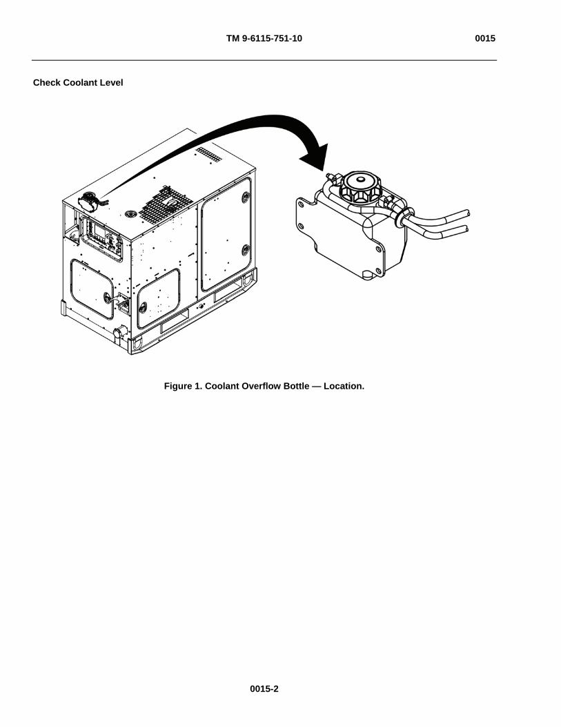
TM 9-6115-751-10 0015
Check Coolant Level
Figure 1. Coolant Overflow Bottle — Location.
0015-2
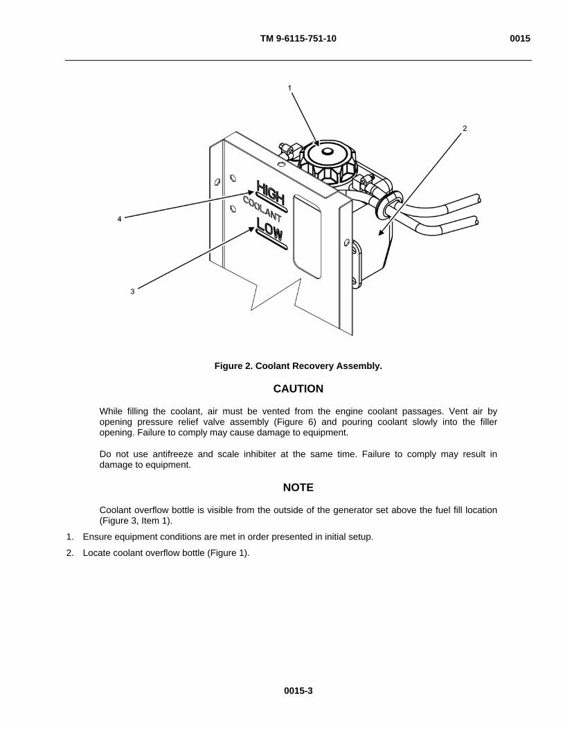
TM 9-6115-751-10 0015
Figure 2. Coolant Recovery Assembly.
CAUTION
While filling the coolant, air must be vented from the engine coolant passages. Vent air by opening pressure relief valve assembly (Figure 6) and pouring coolant slowly into the filler opening. Failure to comply may cause damage to equipment.
Do not use antifreeze and scale inhibiter at the same time. Failure to comply may result in damage to equipment.
NOTE
Coolant overflow bottle is visible from the outside of the generator set above the fuel fill location (Figure 3, Item 1).
1. Ensure equipment conditions are met in order presented in initial setup.
2. Locate coolant overflow bottle (Figure 1).
0015-3

TM 9-6115-751-10 0015
Figure 3. Coolant Level.
NOTE
The AMMPS 15 kW generator set is shipped from the factory filled with commercial-grade coolant. The color of the commercial-grade coolant may be different from the Mil-Standard coolant with which you are familiar.
The commercial-grade coolant is compatible with the Mil-Standard coolant specified in this manual. Mil-Standard coolant may be used to top-off coolant level prior to the first maintenance interval. Commercial-grade coolant should be drained and replaced with Mil-Standard coolant as directed at the first maintenance interval.
3. Inspect the level of the coolant in the coolant overflow bottle (Figure 2, Item 1) visually.
a. The coolant level should be between the HIGH (Figure 2, Item 4 and Figure 3, Item 2) and LOW (Figure 2, Item 3 and Figure 3, Item 4) marks of the coolant overflow bottle (Figure 2, Item 1).
b. Add coolant if the coolant level is below the LOW (Figure 2, Item 3 and Figure 3, Item 4) level. See Fill Coolant Overflow Bottle task.
END OF TASK
0015-4

TM 9-6115-751-10 0015
Fill Coolant Overflow Bottle
1. Remove radiator cap (Figure 4, Item 1) from radiator.
Figure 4. Radiator Fill — Exterior.
0015-5
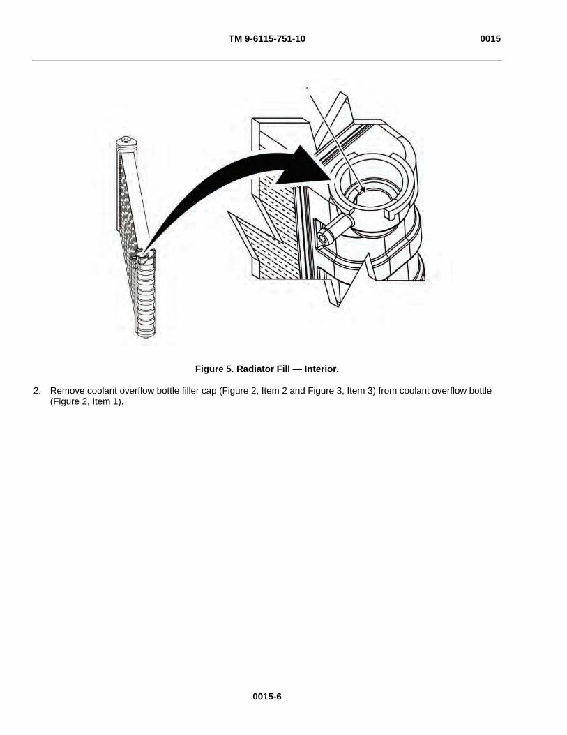
TM 9-6115-751-10 0015
Figure 5. Radiator Fill — Interior.
2. Remove coolant overflow bottle filler cap (Figure 2, Item 2 and Figure 3, Item 3) from coolant overflow bottle (Figure 2, Item 1).
0015-6

TM 9-6115-751-10 0015
Figure 6. Pressure Relief Valve.
3. Open left-side door.
4. Open pressure relief valve (Figure 6, Item 2) on upper radiator hose assembly by lifting the relief valve lever (Figure 6, Item 1) 90 degrees from the position shown.
NOTE
The AMMPS 15 kW generator set is shipped from the factory filled with commercial-grade coolant. The color of the commercial-grade coolant may be different from the Mil-Standard coolant with which you are familiar.
The commercial-grade coolant is compatible with the Mil-Standard coolant specified in this manual. Mil-Standard coolant may be used to top-off coolant level prior to the first maintenance interval. Commercial-grade coolant should be drained and replaced with Mil-Standard coolant as directed at the first maintenance interval.
5. Add coolant until the level reaches the LOW mark (Figure 2, Item 3 and Figure 3, Item 4) on the coolantoverflow bottle (Figure 2, Item 1).
NOTE
The following steps assume there is no coolant present in the coolant overflow bottle (Figure 2, Item 1).
Pour coolant slowly into the radiator to allow trapped air to escape.
6. Fill the radiator with approved coolant until the coolant level reaches the narrow opening at the bottom of the filler neck (Figure 5, Item 1).
0015-7
TM 9-6115-751-10 0015
0015-8
CAUTION
Be sure to close radiator cap (Figure 4, Item 1) and coolant overflow bottle filler cap (Figure 2, Item 2 and Figure 3, Item 3) securely to avoid coolant leakage. Engine may overheat if radiator cap (Figure 4, Item 1) and/or coolant overflow bottle filler cap (Figure 2, Item 2 and Figure 3, Item 3) is loose. Failure to comply may cause damage to equipment.
7. Inspect for missing, unattached, damaged, and/or cracked radiator or coolant overflow bottle filler cap (Figure 2, Item 2 and Figure 3, Item 3) and/or gaskets.
8. Contact field maintenance for missing, unattached, damaged, and/or cracked radiator or coolant overflow bottle filler cap (Figure 2, Item 2 and Figure 3, Item 3) and/or gaskets.
9. Reinstall radiator cap (Figure 4, Item 1).
10. Reinstall coolant overflow bottle filler cap (Figure 2, Item 2 and Figure 3, Item 3).
11. Return the relief valve lever (Figure 6, Item 3) to original position as shown in Figure 6.
12. Wipe up any spilled coolant and dispose of IAW local SOP.
13. Close left-side door.
14. Start engine and operate until the engine has reached 195°F (90°C) (WP 0005, Operation Under Usual Conditions).
15. Shut down engine and allow it to cool.
16. Recheck coolant level. See Check Coolant Level task.
17. Fill as required. See Fill Coolant Overflow Bottle task.
END OF TASK

TM 9-6115-751-10 0015
Inspect Radiator Hoses, Interconnecting Tubes, and Clamps
Figure 7. Cooling System Hoses, Interconnecting Tubes, and Clamps — Left Side.
1. Open right- and left-side access doors.
CAUTION
Loss of coolant may be caused by leaks in the cooling system. Visually inspect all cooling system hoses and clamps, as well as radiator and coolant overflow bottle for signs of coolant leaks. Operation is permitted with Class I or II leaks present. Notify field maintenance of all leaks. If a Class III leak is found, do not operate the generator set. Failure to comply may cause damage to equipment.
NOTE
Upper radiator hose assemblies to be inspected begin at the connection to the radiator at the unit bulkhead (Figure 7, Item 1) and end at the connection to the thermostat (Figure 7, Item 3) on the front of the engine.
Lower radiator hose assemblies to be inspected begin at the connection to the radiator at the unit bulkhead (Figure 7, Item 2) and end at the connection to the water pump (Figure 7, Item 4) on the front of the engine. The drain hose (Figure 8, Item 2) is part of the lower radiator assembly.
2. Inspect the upper radiator hose assemblies (Figure 7) through the left-side door visually for damage, wear, fraying, loose connections, or corrosion to hose clips and clamp bands.
3. Inspect the pressure relief valve assembly (Figure 6) visually for damage, wear, fraying, loose connections, or corrosion to hose clips and clamp bands.
0015-9

TM 9-6115-751-10 0015
Figure 8. Cooling System Hoses, Interconnecting Tubes, and Clamps — Right Side.
4. Inspect the lower radiator hose assemblies (Figure 8) through the right-side door visually for damage, wear, fraying, loose connections, or corrosion to hose clips and clamp bands.
WARNING
Do not operate generator set if any fuel leaks are present. Fuel is combustible. Always perform PMCS before operation. Failure to comply may cause injury or death to personnel.
5. Inspect winterization kit (Figure 8, Item 1) coolant hoses and fuel hoses visually for damage, wear, fraying, loose connections, or corrosion to hose clips and clamp bands.
CAUTION
Do not operate the generator set if class III coolant leaks are present. Failure to comply will cause damage to equipment.
6. Notify field maintenance of any leaks, damage, or corrosion.
7. Close right- and left-side access doors.
END OF TASK
END OF WORK PACKAGE
0015-10

TM 9-6115-751-10 0016
0016-1
OPERATOR MAINTENANCE
AMMPS 15KW GENERATOR SET
SERVICE FUEL SYSTEM
INITIAL SETUP:
Test Equipment
Not Applicable
Tools and Special Tools
Not Applicable
Materials/Parts
Fuel, diesel (WP 0021, Expendable and Durable Items List, Item 4)
Pan, drip (WP 0021, Item 8)
Materials/Parts
Rags, wiping (WP 0021, Item 9)
Personnel Required
Operator (1)
References
Not Applicable
Equipment Conditions
Not Applicable
SERVICE FUEL SYSTEM
WARNING
Hearing protection is required during maintenance or repair with engine running. Failure to comply can cause hearing loss.
When operating, generator set engine has hot metal surfaces that will burn flesh on contact. Shut down generator set and allow engine to cool before checks, services, and maintenance. Wear gloves and additional protective clothing as required. Failure to comply may cause injury or death to personnel.
Fuels used in the generator set are combustible. Do not smoke or use open fire when performing maintenance. Fire and possible explosion may result. Failure to comply may cause injury or death to personnel and damage to equipment.
Fuel is combustible and toxic to eyes, skin, and respiratory tract. Skin and eye protection are required when working in contact with fuel. Avoid repeated or prolonged contact. Provide adequate ventilation. Operators are to wash skin and change clothing promptly if in contact with fuel. Failure to comply may cause injury or death to personnel.
Hot engine surfaces from engine and generator circuitry are possible sources of ignition. When hot refueling during unit operation with DF-1, DF-2, JP5, or JP8, avoid fuel splash and fuel spill. Do not smoke or use open flame when performing refueling. Remember PMCS are still required. Flames and possible explosion may result. Failure to comply may cause injury or death to personnel.
While inspecting the operation of the generator set, do not inadvertently reach into the generator set. Failure to comply can cause injury or death to personnel.

TM 9-6115-751-10 0016
Check Fuel Level
Figure 1. Fuel Fill — Location.
1. Locate the fuel fill area (Figure 1) on the rear panel of the unit.
NOTE
Refueling is permitted while the generator set is operating.
2. Clean any dirt or debris from the fuel filler cap (Figure 2, Item 2) area.
3. Turn the fuel filler cap (Figure 2, Item 2) counterclockwise to the first detent to relieve any pressure in the fuel tank.
0016-2

TM 9-6115-751-10 0016
Figure 2. Fuel Filler.
4. Remove the fuel filler cap (Figure 2, Item 2) from the fuel filler neck (Figure 2, Item 1) by turning counterclockwise beyond the first detent. Note orientation of fuel filler cap (Figure 2, Item 2) to aid in installation.
CAUTION
DCS screen shows fuel level as a percentage of capacity and is reported from the electronic gage. Always verify need for fuel by sight before adding fuel. Failure to comply may cause damage to the equipment.
5. Observe level of fuel in the fuel filler neck (Figure 2, Item 1). If level is below the indicator plate/fuel filler neck screen (Figure 2, Item 4) in the fuel filler neck (Figure 2, Item 1), additional fuel is required.
6. Replace fuel filler cap (Figure 2, Item 2) using orientation noted in step 4. Turn clockwise to second detent.
END OF TASK
0016-3
TM 9-6115-751-10 0016
0016-4
Fill Fuel Tank
1. Remove fuel filler cap (Figure 2, Item 2). See Check Fuel Level task.
WARNING
Fuels used in the generator set are combustible. Ensure fuel source grounding strap is connected to unit fuel fill grounding stud (fuel fill static grounding). When filling the fuel tank, maintain metal-to-metal contact between filler nozzle and fuel tank opening to eliminate ESD. Fire and possible explosion can result. Failure to comply may cause injury or death to personnel.
2. Attach grounding strap (fuel fill static ground) from fuel source to grounding stud (fuel fill static ground) (Figure 2, Item 3) on fuel filler neck (Figure 2, Item 1).
NOTE
Refueling while the generator set is operating is permitted.
3. Add approved fuel until the level of fuel is at the indicator plate/fuel filler neck screen (Figure 2, Item 4) in the fuel filler neck.
4. Clean any spilled fuel and dispose of IAW local SOP.
5. Replace fuel filler cap (Figure 2, Item 2). See Check Fuel Level task.
6. Remove grounding strap from grounding stud (fuel fill static ground) (Figure 2, Item 3) on fuel filler neck (Figure 2, Item 1).
END OF TASK
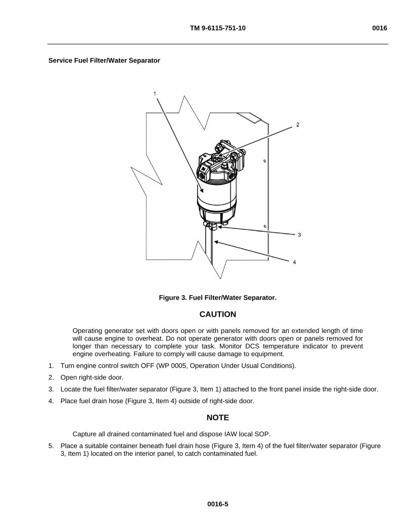
TM 9-6115-751-10 0016
Service Fuel Filter/Water Separator
Figure 3. Fuel Filter/Water Separator.
CAUTION
Operating generator set with doors open or with panels removed for an extended length of time will cause engine to overheat. Do not operate generator with doors open or panels removed for longer than necessary to complete your task. Monitor DCS temperature indicator to prevent engine overheating. Failure to comply will cause damage to equipment.
1. Turn engine control switch OFF (WP 0005, Operation Under Usual Conditions).
2. Open right-side door.
3. Locate the fuel filter/water separator (Figure 3, Item 1) attached to the front panel inside the right-side door.
4. Place fuel drain hose (Figure 3, Item 4) outside of right-side door.
NOTE
Capture all drained contaminated fuel and dispose IAW local SOP.
5. Place a suitable container beneath fuel drain hose (Figure 3, Item 4) of the fuel filter/water separator (Figure 3, Item 1) located on the interior panel, to catch contaminated fuel.
0016-5
TM 9-6115-751-10 0016
0016-6
NOTE To drain the fluid within the fuel filter/water separator (Figure 3, Item 1) at a greater rate of speed than gravity drain, a pump plunger (Figure 3, Item 2) can be employed to eject the fluid.
6. Turn pump plunger (Figure 3, Item 2) in a counterclockwise direction to loosen pump plunger.
7. Extend pump plunger (Figure 3, Item 2) upward to full height. 8. Open fuel drain valve (Figure 3, Item 3) on the bottom of the fuel filter/water separator (Figure 3, Item 1) to
allow contaminated fuel to drain into the suitable container.
9. Depress pump plunger (Figure 3, Item 2) until at the bottom of stroke to eject fluid in the fuel filter/water separator (Figure 3, Item 1) into the suitable container.
10. Repeat steps 7 through 9 as required until no contamination is seen in flow.
11. Close the fuel drain valve (Figure 3, Item 3) on the bottom of the fuel filter/water separator (Figure 3, Item 1) once the drain flow is clean.
12. Turn pump plunger (Figure 3, Item 2) in a clockwise direction until tight.
13. Clean any spilled or contaminated fuel and dispose of IAW local SOP.
CAUTION
Operating generator set with doors open or with panels removed for an extended length of time will cause engine to overheat. Do not operate generator with doors open or panels removed for longer than necessary to complete your task. Monitor DCS temperature indicator to prevent engine overheating. Failure to comply will cause damage to equipment.
14. Start engine and check for leaks and proper operation.
15. Close right-side door.
END OF TASK
END OF WORK PACKAGE
TM 9-6115-751-10 0017
0017-1
OPERATOR MAINTENANCE
AMMPS 15KW GENERATOR SET
SERVICE ENGINE OIL
INITIAL SETUP:
Test Equipment
Not Applicable
Tools and Special Tools
Not Applicable
Materials/Parts
Oil, lubricating (WP 0021, Expendable and Durable Items List, Item 7)
Rag, wiping (WP 0021, Item 9)
Materials/Parts
Sample bottle, plastic, 3 ounce (oz) (WP 0021, Item 10)
Personnel Required
Operator (1)
References
TB-43-0211
Equipment Conditions
Not Applicable
SERVICE ENGINE OIL
WARNING
Wear heat-resistant gloves and avoid contacting hot metal surfaces with hands and exposed skin after components have been heated. Wear additional protective clothing as required. Failure to comply may cause injury or death to personnel.
Check Oil Level of Engine Not In-Service
CAUTION
When using an oil of a different make or viscosity from the previous oil, contact field maintenance to drain oil before servicing engine oil. Never mix two different types of oil. Failure to comply may cause damage to equipment.
Ensure oil level remains between the marks on the dipstick. Too much oil may cause a drop in output or excessive blow-by gas and will raise engine oil pressure, which may cause internal engine oil seals to fail. Too little oil may seize rotating and/or sliding engine parts due to insufficient or non-existent lubrication. Failure to comply may cause damage to equipment.
Keep all lubricants in closed containers and store in a clean, dry place away from external heat. Allow no dust, dirt, or other foreign material to mix with the lubricants. Keep all lubrication equipment clean and ready for use. Failure to comply may cause damage to equipment.
NOTE
Keep all external parts not requiring lubrication free of lubricants. Before lubricating the generator set, wipe all lubrication points free of dirt and grease. Clean all lubrication points after lubricating to prevent accumulation of foreign matter.
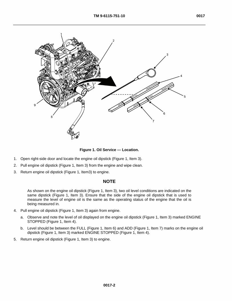
TM 9-6115-751-10 0017
Figure 1. Oil Service — Location.
1. Open right-side door and locate the engine oil dipstick (Figure 1, Item 3).
2. Pull engine oil dipstick (Figure 1, Item 3) from the engine and wipe clean.
3. Return engine oil dipstick (Figure 1, Item3) to engine.
NOTE
As shown on the engine oil dipstick (Figure 1, Item 3), two oil level conditions are indicated on the same dipstick (Figure 1, Item 3). Ensure that the side of the engine oil dipstick that is used to measure the level of engine oil is the same as the operating status of the engine that the oil is being measured in.
4. Pull engine oil dipstick (Figure 1, Item 3) again from engine.
a. Observe and note the level of oil displayed on the engine oil dipstick (Figure 1, Item 3) marked ENGINE STOPPED (Figure 1, Item 4).
b. Level should be between the FULL (Figure 1, Item 6) and ADD (Figure 1, Item 7) marks on the engine oil dipstick (Figure 1, Item 3) marked ENGINE STOPPED (Figure 1, Item 4).
5. Return engine oil dipstick (Figure 1, Item 3) to engine.
0017-2
TM 9-6115-751-10 0017
0017-3
CAUTION
Improper oil level may cause internal engine failure. Oil level too high will raise engine oil pressure, which may lead to failure of internal engine oil seals. Oil level too low may result in failure of internal engine components due to non-lubrication. Failure to comply may cause damage to equipment.
6. Add approved engine oil if required. See Add Engine Oil task.
7. Repeat steps 2 through 5 if engine oil was added to engine.
8. Contact field maintenance for assistance if oil level is too high.
9. Wipe up any spilled engine oil and dispose of oil-soaked materials IAW local SOP.
10. Close right-side door.
END OF TASK
Check Oil Level of Operating Engine
WARNING
Operating generator set with unit doors open or panels removed exposes personnel to a high noise level. Close unit doors and replace panels or wear hearing protection while operating or working near an operating generator set. Failure to comply may cause injury or death to personnel.
Metal jewelry can conduct electricity and become entangled in generator set components. Remove all jewelry and do not wear loose clothing when working on equipment. Failure to comply may cause injury or death to personnel.
While inspecting the operation of the generator set, do not inadvertently reach into the generator set. Failure to comply can cause injury or death to personnel.
Flying debris or material may enter eyes or strike the face. Wear appropriate eye/face protection while performing maintenance tasks. Failure to comply may cause injury or death to personnel.
CAUTION
Improper oil level may cause internal engine failure. Oil level too high will raise engine oil pressure, which may lead to failure of internal engine oil seals. Oil level too low may result in failure of internal engine compartments due to non-lubrication. Failure to comply may cause damage to equipment.
Operating generator set with doors open or with panels removed for an extended length of time will cause engine to overheat. Do not operate generator with doors open or panels removed for longer than necessary to complete your task. Monitor DCS temperature indicator to prevent engine overheating. Failure to comply will cause damage to equipment.
NOTE
The engine oil level may be checked and oil may be added with the engine operating. Whenever possible, stop the generator set prior to servicing oil system.
1. Open right-side door and locate engine oil dipstick (Figure 1, Item 3).
2. Pull engine oil dipstick (Figure 1, Item 3) from the engine and wipe clean.
TM 9-6115-751-10 0017
0017-4
3. Return engine oil dipstick (Figure 1, Item 3) to engine.
4. Pull engine oil dipstick (Figure 1, Item 3) again from the engine.
a. Observe and note the level of oil displayed on the engine oil dipstick (Figure 1, Item 3) marked ENGINE RUNNING (Figure 1, Item 5).
b. Level should be between the FULL (Figure 1, Item 6) and ADD (Figure 1, Item 7) marks on the engine oil dipstick (Figure 1, Item 3) marked ENGINE RUNNING (Figure 1, Item 5).
5. Return engine oil dipstick (Figure 1, Item 3) to engine.
6. Add approved engine oil if required. See Add Engine Oil task.
7. Repeat steps 2 through 6 if engine oil was added to engine.
8. Contact field maintenance for assistance if oil level is too high.
9. Examine areas adjacent to the oil cooler (Figure 1, Item 1) and spin-on oil filter (Figure 1, Item 8) visually for evidence of leakage.
10. Contact field maintenance if there is evidence of leakage.
11. Wipe up any spilled engine oil and dispose of oil-soaked materials IAW local SOP.
12. Close right-side door.
END OF TASK
Collect Engine Oil Sample
NOTE
The value of an oil sample is wholly dependent on whether the lubricant has circulated in the component long enough to accumulate and mix wear metal concentrations uniformly.
1. Perform Check Oil Level of Engine Not In Service task or Check Oil Level of Operating Engine task to determine if oil level is adequate to withdraw a sample.
2. Start generator set and operate for approximately 5 minutes to warm and circulate engine oil if engine was not operating in-service.
3. Open right-side door and locate oil sample collection valve (Figure 1, Item 9).
4. Place a wiping rag under the oil sample collection valve (Figure 1, Item 9) outlet to absorb purge oil.
CAUTION
Oil that has been trapped within the oil sample collection valve (Figure 1, Item 9) must be purged to prevent a false sample. Engine oil of an operating generator set can reach temperatures in excess of 150°F (65°C) at pressures greater than 80 psi. The time required to open the oil sample collection valve (Figure 1, Item 9) to clear the oil sample collection valve (Figure 1, Item 9) of possible contaminated oil should be momentary. Keeping the oil sample collection valve (Figure 1, Item 9) open for an extended period of time will reduce oil level. Failure to comply may cause damage to equipment.
5. Push oil sample collection valve (Figure 1, Item 9) toggle toward engine to release purge oil, then release.
6. Wipe valve outlet with a clean rag.
7. Place uncapped oil sample collection bottle under valve outlet.
8. Push oil sample collection valve (Figure 1, Item 9) toggle toward engine and hold until oil is within 1/2 in from sample bottle opening.

TM 9-6115-751-10 0017
0017-5/6 blank
9. Cap sample bottle.
10. Wipe up any spilled oil and dispose of oil-soaked materials IAW local SOP.
11. Turn engine control switch to OFF position if generator set was started only to retrieve an oil sample.
12. Perform Check Oil Level of Engine not in Service task or Check Oil Level of Operating Engine task.
13. Record information on oil sample bottle as outlined in TB-43-0211 (AOAP).
Add Engine Oil
CAUTION
Improper oil level may cause internal engine failure. Oil level too high will raise engine oil pressure, which may lead to failure of internal engine oil seals. Oil level too low may result in failure of internal engine compartments due to non-lubrication. Failure to comply may cause damage to equipment.
NOTE
Engine oil level is determined and noted by performing Check Oil Level of Engine Not In-Service task or Check Oil Level of Operating Engine task.
The engine oil level may be checked and oil may be added with the engine operating. Whenever possible, stop the generator set prior to servicing oil system.
1. Open right-side door and locate oil filler cap (Figure 1, Item 2).
2. Remove oil filler cap (Figure 1, Item 2).
3. Add additional oil as required to raise the oil level to the FULL (Figure 1, Item 6) mark on the engine oil dipstick (Figure 1, Item 3).
4. Return oil filler cap (Figure 1, Item 2) to engine.
5. Perform Check Oil Level of Engine Not In-Service task, steps 1 through10 or Check Oil Level of Operating Engine task, steps 1 through 12.
END OF TASK
END OF WORK PACKAGE


TM 9-6115-751-10
CHAPTER 5
SUPPORTING INFORMATION FOR
AMMPS 15KW GENERATOR SET

TM 9-6115-751-10
CHAPTER 5
SUPPORTING INFORMATION
WORK PACKAGE INDEX
Title WP Sequence No.
REFERENCES..................................................................................................................................................... 0018
COMPONENTS OF END ITEM (COEI) AND BASIC ISSUE ITEMS (BII) LIST.................................................. 0019
ADDITIONAL AUTHORIZATION LIST (AAL) ...................................................................................................... 0020
EXPENDABLE AND DURABLE ITEMS LIST...................................................................................................... 0021
TM 9-6115-751-10 0018
0018-1
OPERATOR MAINTENANCE
AMMPS 15KW GENERATOR SET
REFERENCES
SCOPE
This WP lists all the FM, forms, TMs, and miscellaneous publications referenced in this TM.
FIELD MANUALS
FM 11-487-4 Installation Practices: Grounding, Bonding, and Shielding FM 5-424 Theater of Operations Electrical Systems FM 31-70 Basic Cold Weather Manual FM 4-25.11 First Aid FM 3-11.5 Multiservice Tactics, Techniques, and Procedures for Chemical, Biological,
Radiological, and Nuclear Decontamination FM 3-5 NBC Decontamination FM 3-4 NBC Protection FM 3-3 Chemical and Biological Contamination Avoidance
FORMS
AFI 21-101 Aircraft and Equipment Maintenance Management AFI 33-201 Air Force Instruction, Communications Security AFR 900-4 Product Quality Deficiency Report (PQDR) Air Force Technical Order (AFTO) Form 22
Technical Manual (TM) Change Recommendation and Reply
AR 25-30 The Army Publishing Program AR 700-138 Army Logistics Readiness and Sustainability CTA 50-909 Field and Garrison Furnishings and Equipment CTA 50-970 Expendable/Durable Items (Except Medical Class V Repair Parts, and
Heraldic Items) CTA 8-10 Army Medical Department Expendable/Durable Items DA Form 2028 Recommended Changes to Publications and Blank Forms DA Form 2404 Equipment Inspection and Maintenance Worksheet DA Form 5988E Equipment Inspection and Maintenance Worksheet (electronic version) DA PAM 738-751 Functional Users Manual for The Army Maintenance Management System
— Aviation (TAMMS-A) DA PAM 750-8 The Army Maintenance Management System (TAMMS) Users Manual MCO P4855.10 Product Quality Deficiency Report (PQDR) NAVMC Form 10772 Recommended Changes to Technical Publications SF 368 Product Quality Deficiency Report (PQDR) TO 00-20 Series of Technical Orders

TM 9-6115-751-10 0018
0018-2
TECHNICAL MANUALS
NMWR-9-6115-751 National Maintenance Works Requirement manual for the 15 kW AMMPS Generator Sets
TB-43-0211 Army Oil Analysis Program (AOAP) Guide for Leaders and Users TM 1-1500-344-23 Aircraft Weapon Systems Cleaning and Corrosion Control TM 750-244-2 Procedures for Destruction of Equipment to Prevent Enemy Use TM 4700-15/1 Preventive Maintenance Checks and Services Roster (4700) TM 9-6115-751-13&P Operator and Field Maintenance Manual Including Repair Parts and
Special Tools List (RPSTL) for Generator Set, Trailer Mounted 15 kW Advanced Medium Mobile Power Sources (AMMPS)
TM 9-6115-751-24&P Field and Sustainment Maintenance Manual Including Repair Parts and Special Tools List (RPSTL) for the 15 kW AMMPS Generator Sets
MISCELLANEOUS DOCUMENTS
MIL-PRF-2104H Performance Specification, Lubrication Oil, Internal Combustion Engine, Combat/Tactical Service
MIL-PRF-21260E Performance Specification, Lubrication Oil, Internal Combustion Engine, Preservative Break-In
MIL-PRF-46167C Performance Specification, Lubrication Oil, Internal Combustion Engine, Arctic
END OF WORK PACKAGE

TM 9-6115-751-10 0019
0019-1
OPERATOR MAINTENANCE
AMMPS 15KW GENERATOR SET
COMPONENTS OF END ITEM (COEI) AND BASIC ISSUE ITEMS (BII) LISTS
INTRODUCTION
Scope
This work package provides COEI and BII lists for the AMMPS 15 kW generator set to help you inventory items for safe and efficient operation of the equipment.
General
The COEI and BII information is divided into the following lists:
Components of End Item (COEI). This list is for information purposes only and is not authority to requisition replacements. These items are part of the AMMPS. As part of the end item, these items must be with the end item whenever it is issued or transferred between property accounts. Items of COEI are removed and separately packaged for transportation or shipment only when necessary. Illustrations are furnished to help you find and identify the items.
Basic Issue Item (BII). These essential items are required to place the AMMPS in operation, operate it, and to do emergency repairs. Although shipped separately packaged, BII must be with the AMMPS during operation and when it is transferred between property accounts. Listing these items is your authority to request/requisition them for replacement based on authorization of the end item by the TOE/MTOE. Illustrations are furnished to help you find and identify the items.
Explanation of Columns in the COEI List and BII List
Column (1) Illus. Number. Gives you the number of the item illustrated.
Column (2) National Stock Number (NSN). Identifies the stock number of the item to be used for requisitioning purposes.
Column (3) Description, Part Number/(CAGEC). Identifies the Federal item name (in all capital letters) followed by a minimum description when needed. The stowage location of COEI and BII is also included in this column. The last line below the description is the part number and the Commercial and Government Entity Code (CAGEC) (in parentheses).
Column (4) Usable On Code. When applicable, gives you a code if the item you need is not the same for different models of equipment. These codes are identified below.
Code Used on
98J Model MEP 1050
98K Model MEP 1051
Column (5) U/I. Unit of Issue (U/I) indicates the physical measurement or count of the item as issued per the National Stock Number shown in column (2).
Column (6) Qty Rqr. Indicates the quantity required.
There are no COEI items for the AMMPS 15 kW skid-mounted generator sets.
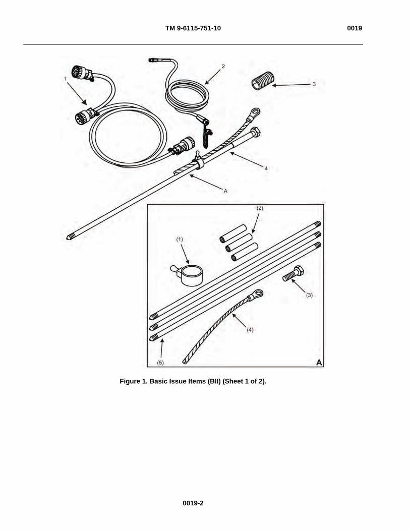
TM 9-6115-751-10 0019
Figure 1. Basic Issue Items (BII) (Sheet 1 of 2).
0019-2

TM 9-6115-751-10 0019
Figure 1. Basic Issue Items (BII) (Sheet 2 of 2).
Table 2. Basic Issue Items (BII).
(1) ILLUS. NUMBER
(2) NATIONAL STOCK NUMBER (NSN)
(3) DESCRIPTION, PART NUMBER/(CAGEC)
(4) USABLE ON CODE
(5) U/I
(6) QTY RQR
1 6150-01-406-9533 CABLE, PARALLELING 88-22209
Not Applicable
EA 1
2 4720-00-021-3320 FUEL LINE, AUXILIARY 69-668
Not Applicable
EA 1
3 OIL DRAIN EXTENSION PIPE Not Applicable
EA 1
4 5975-00-296-5324 ROD, GROUNDING, ASSY. (1) CLAMP (2) COUPLING (3) (3) DRIVING STUD (4) GROUND CABLE (5) GROUND ROD (3)
Not Applicable
EA 1
5 TM 9-6115-751-10 Not Applicable
EA 1
END OF WORK PACKAGE
0019-3/4 blank


TM 9-6115-751-10 0020
0020-1/2 blank
OPERATOR MAINTENANCE
AMMPS 15KW GENERATOR SET
ADDITIONAL AUTHORIZATION LIST (AAL)
INTRODUCTION
Scope
This work package lists additional items you are authorized for the support of the AMMPS 15 kW generator set.
General
This list identifies items that do not have to accompany the AMMPS 15 kW generator set and that do not have to be turned in with it. These items are all authorized to you by CTA, MTOE, TDA, or JTA.
Explanation of Columns in the AAL
Column (1) National Stock Number (NSN). Identifies the stock number of the item to be used for requisitioning purposes.
Column (2) Description, Part Number/(CAGEC). Identifies the Federal item name (in all capital letters) followed by a minimum description when needed. The last line below the description is the part number and the Commercial and Government Entity Code (CAGEC) (in parentheses).
Column (3) Usable On Code. When applicable, gives you a code if the item you need is not the same for different models of equipment. These codes are identified below.
Code Used on
98J Model MEP 1050
98K Model MEP 1051
Column (4) U/I. Unit of Issue (U/I) indicates the physical measurement or count of the item as issued per the National Stock Number shown in column (1).
Column (5) Qty Recom. Indicates the quantity recommended.
Table 1. Additional Authorization List.
(1) (2) (3) (4) (5) NATIONAL STOCK NUMBER (NSN) DESCRIPTION, PART NUMBER/(CAGEC)
USABLE ON CODE U/I
QTY RECOM.
CABLE, LOCAL CONTROL, 04-21226/(44940) N/A EA 1 CABLE, REMOTE CONTROL, 04-21227/(44940) N/A EA 1 5120-00-251-4489 HAMMER, HAND, ENGINEERS, DOUBLE, 8# A-A-
1293/(58536) N/A EA 1
5120-01-013-1676 SLIDE HAMMER, GROUND ROD 13226E7741/(97403)
N/A EA 1
END OF WORK PACKAGE


TM 9-6115-751-10 0021
OPERATOR MAINTENANCE
AMMPS 15KW GENERATOR SET
EXPENDABLE AND DURABLE ITEMS LIST
INTRODUCTION
Scope
This work package lists expendable and durable items that you will need to operate and maintain the AMMPS generator set. This list is for information only and is not authority to requisition the listed items. These items are authorized to you by CTA 50-970, Expendable/Durable Items (Except Medical, Class V, Repair Parts, and Heraldic Items), CTA 50-909, Field and Garrison Furnishings and Equipment, or CTA 8-10, Army Medical Department Expendable/Durable Items.
Explanation of Columns in the Expendable/Durable Items List
Column (1) Item No. This number is assigned to the entry in the list and is referenced in the narrative instructions to identify the item (e.g., Use brake fluid (WP 0098, Item 5)).
Column (2) Level. This column identifies the lowest level of maintenance that requires the listed item (C = Crew).
Column (3) National Stock Number (NSN). This is the NSN assigned to the item which you can use to requisition it.
Column (4) Item Name, Description, Part Number/(CAGEC). This column provides the other information you need to identify the item. The last line below the description is the part number and the Commercial and Government Entity Code (CAGEC) (in parentheses).
Column (5) U/I. Unit of Issue (U/I) code shows the physical measure or count of an item, such as gallon, dozen, gross, etc.
Table 1. Expendable and Durable Items.
(1) (2) (3) (4) (5) ITEM NO. LEVEL
NATIONAL STOCK NUMBER (NSN)
ITEM NAME, DESCRIPTION, PART NUMBER/(CAGEC) U/I
1 C 6850-00-181-7933 Antifreeze MIL-A-46153 (81349) Bottle 2 C 1660-99-783-4056 Element, air cleaner filter EA 3 C 6230-00-163-1856 Flashlight, 928572/(24617) Each (EA) 4 C 9140-00-000-0184 Fuel, diesel AA 52557 Gal 5 C 4940-01-120-6793 Funnel, flexible EA 6 C 9150-00-079-7374 Oil, engine SAE 30 qt 7 C 9150-00-186-6681 Oil, lubricating MIL-PRF-2104H (81349) qt 8 C 1615-01-322-0311 Pan, drip 145S1112-26 (77272) EA 9 C 7920-00-140-0869 Rag, wiping 8722-0088 (03950) Box 10 C 8125-01-082-9697 Sample bottle, plastic, 3 ounce (oz) EA 11 C 6810-00-107-1510 Water, distilled O-C-265 (81348) Drum
END OF WORK PACKAGE
0021-1/2 blank


TM 9-6115-751-10
Glossary-1/ Glossary-2 blank
GLOSSARY
SCOPE
This WP defines all of the terms used in the AMMPS 15 kW generator set TM.
TERM DEFINITION Adjustment hints indicator Portion of the DCS display which shows functional soft keys to use during
adjustment. Automatic Voltage Regulator (AVR)
Electrical regulator designed to automatically maintain a constant voltage level. Important component in synchronous generators, it controls the output voltage of the generator by controlling its excitation.
Exciter A device that supplies DC to the field coils of a synchronous generator, producing the magnetic flux required for inducing output voltage in the armature coils (stator).
Gain The measure of the ability of a generator to increase the amplitude of voltage from the input to the output. It is usually defined as the mean ratio of the signal output of a system to the signal input of the same system.
Ground Fault Protection (GFP) Circuitry designed to protect personnel from line-to-ground fault currents. Line-to-Line (L-L) Voltage The voltage between any two phases of an AC generator. Line-to-Neutral (L-N) Voltage The voltage between a phase and the common neutral where the three
phases are tied together in a 3-phase, 4-wire, Y-connected generator. Load factor The ratio of the average load to the generator set power rating. Offset Ratio of the variation in the point at which two related sine waves cross
zero. Parallel operation The operation of two or more AC power sources whose output leads are
connected to a common load. Permanent Magnet Generator (PMG)
A generator whose field is a permanent magnet as opposed to an electro-magnet (wound field).
Power Plant (PP) Two AMMPS generator sets hooked up in parallel with the use of a switch box.
Power Unit (PU) A single AMMPS generator set. Switch box Device utilized for joining two AMMPS in parallel for additional electricity
production. Synchronization Status obtained when an incoming generator set is matched with and in
step to the same frequency, voltage, and phase sequence as the operating power source in a paralleling application.
Unit A Generator set directly wired to the switch box in a PP. Unit A is the first set to be placed on line. This is also called generator set A.
Unit B Generator set directly wired to a connecting cable assembly in a PP. Unit B is the second set to be placed on line. This is also called generator set B.
END OF WORK PACKAGE


TM 9-6115-751-10
Index-1
ALPHABETICAL INDEX
SUBJECT WP SEQUENCE NO.-PAGE NO.
A
Additional Authorization List (AAL) ....................................................................................................... WP 0020
C
Components of End Item (COEI) And Basic Issue Items (BII) Lists ..................................................... WP 0019
D
Descriptions and Use of Operator Controls and Indicators .................................................................. WP 0004
DCS Fault and Warning Codes and Descriptions................................................................................. WP 0011
E
Emergency ............................................................................................................................................ WP 0008
NATO Slave Receptacle Start Operation ....................................................................................... WP 0008-1 Emergency Stopping ...................................................................................................................... WP 0008-3 Operation Using BATTLESHORT Switch....................................................................................... WP 0008-4
Equipment Description and Data .......................................................................................................... WP 0002
Expendable and Durable Items List ...................................................................................................... WP 0021
G
General Information .............................................................................................................................. WP 0001
O
Operation Under Unusual Conditions ................................................................................................... WP 0007
Operation in Extreme Cold -25°F (-31°C)....................................................................................... WP 0007-2 Operation in Extreme Heat Above 120°F (49°C) ........................................................................... WP 0007-2 Operation in Dusty or Sandy Areas................................................................................................ WP 0007-2 Operation in Rainy or Humid Conditions ........................................................................................ WP 0007-3 Operation in Salt Water Areas........................................................................................................ WP 0007-3 Operation in High Altitudes............................................................................................................. WP 0007-4 Operating Using BATTLESHORT Switch....................................................................................... WP 0007-5 Operation While in Contaminated Areas ........................................................................................ WP 0007-6 Use of the Ground Fault Circuit Interrupter (GFCI) Convenience Receptacle............................... WP 0007-7

TM 9-6115-751-10
Index-2
INDEX — Continued.
Operation Under Usual Conditions ....................................................................................................... WP 0005
Siting Requirements ....................................................................................................................... WP 0005-2 Assembly and Preparation for Use................................................................................................. WP 0005-3 Screen Navigation .......................................................................................................................... WP 0005-3 Installation of Ground Rod.............................................................................................................. WP 0005-4 Installation of Auxiliary Fuel Lines .................................................................................................. WP 0005-6 Installation of Load Cables ............................................................................................................ WP 0005-7 Initial Adjustments........................................................................................................................... WP 0005-9 Operating Procedures .................................................................................................................... WP 0005-12 Starting Procedure.......................................................................................................................... WP 0005-12 Adjust Generator Set ...................................................................................................................... WP 0005-18 Monitoring Generator Set Operational Status ................................................................................ WP 0005-23 Operation with Remote Monitoring ................................................................................................. WP 0005-28 Stopping Procedure........................................................................................................................ WP 0005-33 Decals and Instructions Plates ....................................................................................................... WP 0005-34 Preparation for Movement .............................................................................................................. WP 0005-50
P
Parallel Operation ................................................................................................................................. WP 0006
Connecting Generator Sets Parallel Cables (Power Plant Configuration) ..................................... WP 0006-2 Parallel Operation With Switch Box (Two Like Sets)...................................................................... WP 0006-5 Parallel Operation Without Switch Box (Two or More Like Sets) ................................................... WP 0006-8 Adjusting Parallel Operations ........................................................................................................ WP 0006-11 Sort Removal From Parallel Operation With [Unload] Soft Key ..................................................... WP 0006-19 Removal From Parallel Operation With UNIT PARALLEL Switch ................................................ WP 0006-20
PMCS.................................................................................................................................................... WP 0013
PMCS Introduction ................................................................................................................................ WP 0012
R
References............................................................................................................................................ WP 0018
S
Service Air Cleaner ............................................................................................................................... WP 0014
Inspect Air Filter Restriction Indicator ............................................................................................ WP 0014-1 Remove Air Cleaner Filter Element ............................................................................................... WP 0014-3 Install Air Cleaner Filter Element ................................................................................................... WP 0014-4 Clean Air Cleaner Dust Ejector Valve ............................................................................................ WP 0014-4
Service Cooling System........................................................................................................................ WP 0015
Check Coolant Level ...................................................................................................................... WP 0015-2 Fill Coolant Overflow Bottle ........................................................................................................... WP 0015-5 Inspect Radiator Hoses, Interconnecting Tubes, and Clamps ....................................................... WP 0015-9
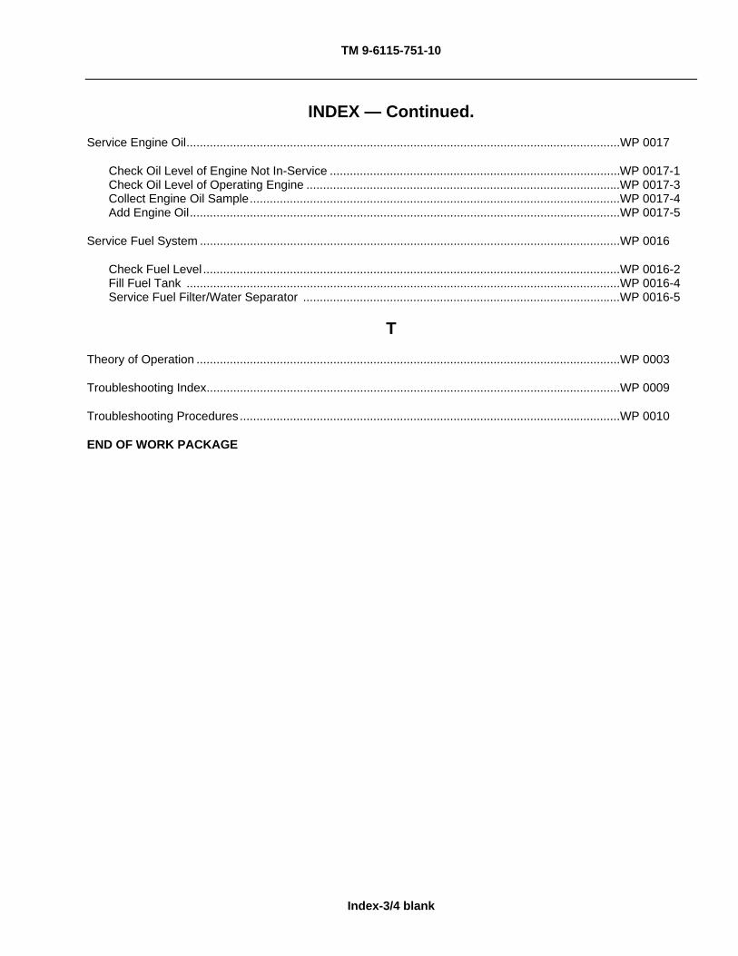
TM 9-6115-751-10
Index-3/4 blank
INDEX — Continued.
Service Engine Oil..................................................................................................................................WP 0017
Check Oil Level of Engine Not In-Service .......................................................................................WP 0017-1 Check Oil Level of Operating Engine ..............................................................................................WP 0017-3 Collect Engine Oil Sample...............................................................................................................WP 0017-4 Add Engine Oil.................................................................................................................................WP 0017-5
Service Fuel System ..............................................................................................................................WP 0016
Check Fuel Level .............................................................................................................................WP 0016-2 Fill Fuel Tank ..................................................................................................................................WP 0016-4 Service Fuel Filter/Water Separator ...............................................................................................WP 0016-5
T
Theory of Operation ...............................................................................................................................WP 0003
Troubleshooting Index............................................................................................................................WP 0009
Troubleshooting Procedures..................................................................................................................WP 0010
END OF WORK PACKAGE

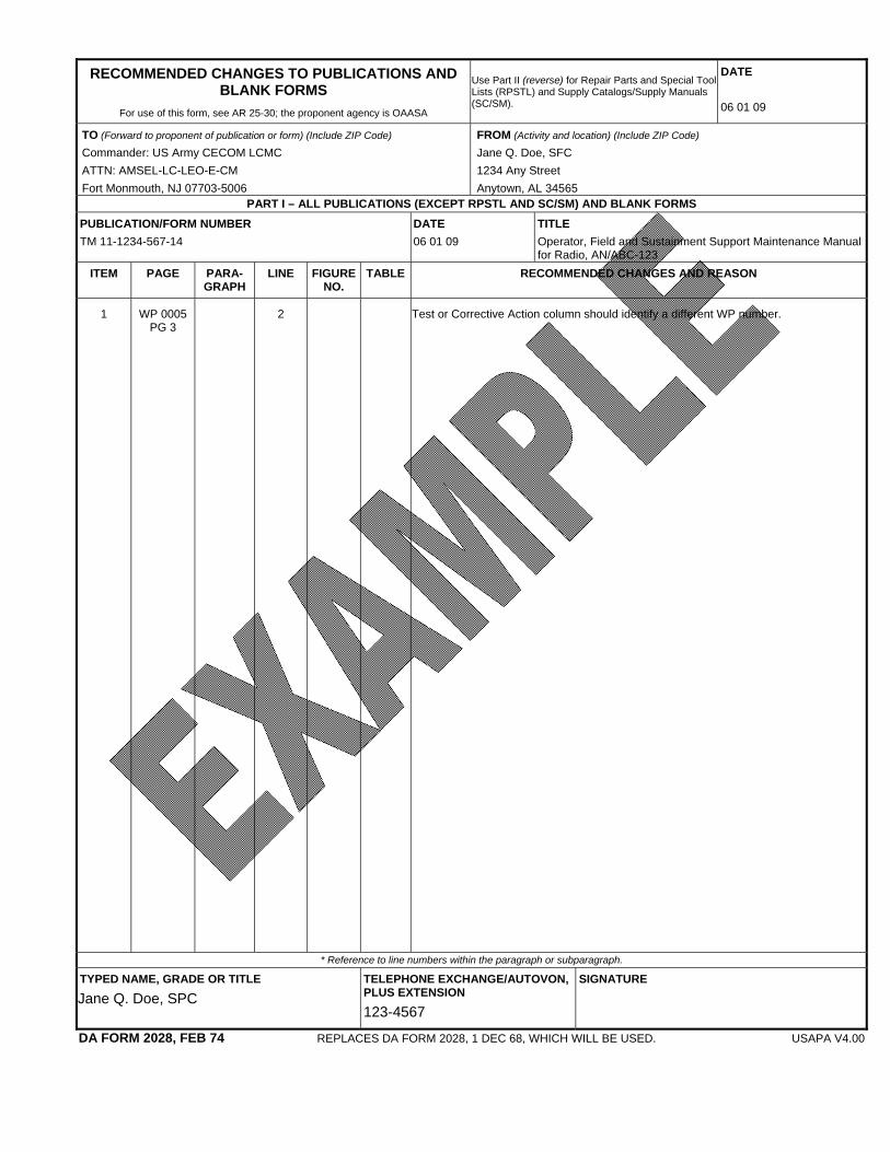
RECOMMENDED CHANGES TO PUBLICATIONS AND BLANK FORMS
For use of this form, see AR 25-30; the proponent agency is OAASA
Use Part II (reverse) for Repair Parts and Special Tool Lists (RPSTL) and Supply Catalogs/Supply Manuals (SC/SM).
DATE 06 01 09
TO (Forward to proponent of publication or form) (Include ZIP Code)
Commander: US Army CECOM LCMC ATTN: AMSEL-LC-LEO-E-CM Fort Monmouth, NJ 07703-5006
FROM (Activity and location) (Include ZIP Code)
Jane Q. Doe, SFC 1234 Any Street Anytown, AL 34565
PART I – ALL PUBLICATIONS (EXCEPT RPSTL AND SC/SM) AND BLANK FORMS PUBLICATION/FORM NUMBER TM 11-1234-567-14
DATE 06 01 09
TITLE Operator, Field and Sustainment Support Maintenance Manual for Radio, AN/ABC-123
ITEM PAGE PARA-GRAPH
LINE FIGURE NO.
TABLE RECOMMENDED CHANGES AND REASON
1 WP 0005 PG 3
2 Test or Corrective Action column should identify a different WP number.
* Reference to line numbers within the paragraph or subparagraph.
TYPED NAME, GRADE OR TITLE
Jane Q. Doe, SPC TELEPHONE EXCHANGE/AUTOVON, PLUS EXTENSION
123-4567
SIGNATURE
DA FORM 2028, FEB 74 REPLACES DA FORM 2028, 1 DEC 68, WHICH WILL BE USED. USAPA V4.00

TO (Forward direct to addressee listed in publication) FROM (Activity and location) (Include ZIP Code) DATE
PART II – REPAIR PARTS AND SPECIAL TOOL LISTS AND SUPPLY CATALOGS/SUPPLY MANUALS PUBLICATION NUMBER TB 9-2590-528-13&P
DATE TITLE INTERROGATION ARM ASSEMBLY (IAA)
PAGE NO.
COLM NO.
LINE NO.
NATIONAL STOCK NUMBER
REFERENCE NO.
FIGURE NO.
ITEM NO.
TOTAL NO. OF MAJOR
ITEMS SUPPORTED
RECOMMENDED ACTION
PART III – REMARKS (Any general remarks, recommendations, or suggestions for improvement of publications and blank forms. Additional blank sheets may be used if more space is needed.)
TYPED NAME, GRADE OR TITLE
Jane Q. Doe, SPC TELEPHONE EXCHANGE/AUTOVON, PLUS EXTENSION
123-4567
SIGNATURE
USAPA V4.00
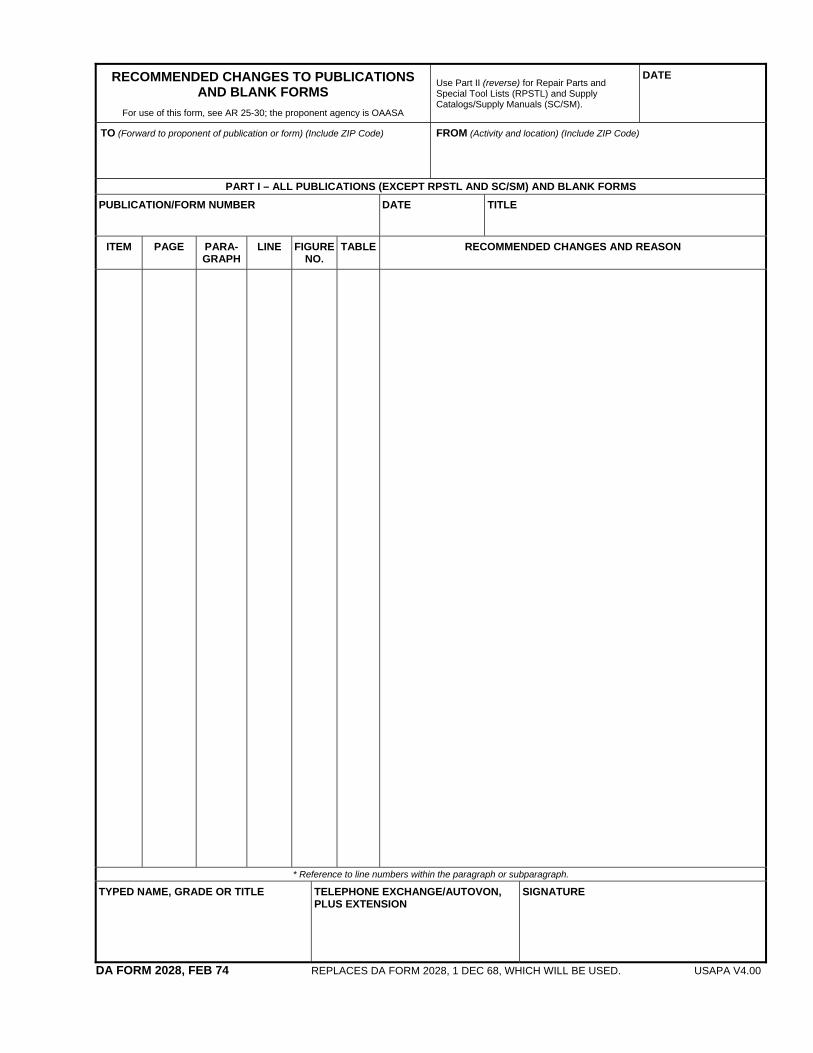
RECOMMENDED CHANGES TO PUBLICATIONS AND BLANK FORMS
For use of this form, see AR 25-30; the proponent agency is OAASA
Use Part II (reverse) for Repair Parts and Special Tool Lists (RPSTL) and Supply Catalogs/Supply Manuals (SC/SM).
DATE
TO (Forward to proponent of publication or form) (Include ZIP Code) FROM (Activity and location) (Include ZIP Code)
PART I – ALL PUBLICATIONS (EXCEPT RPSTL AND SC/SM) AND BLANK FORMS PUBLICATION/FORM NUMBER
DATE
TITLE
ITEM PAGE PARA-GRAPH
LINE FIGURE NO.
TABLE RECOMMENDED CHANGES AND REASON
* Reference to line numbers within the paragraph or subparagraph.
TYPED NAME, GRADE OR TITLE TELEPHONE EXCHANGE/AUTOVON, PLUS EXTENSION
SIGNATURE
DA FORM 2028, FEB 74 REPLACES DA FORM 2028, 1 DEC 68, WHICH WILL BE USED. USAPA V4.00

TO (Forward direct to addressee listed in publication) FROM (Activity and location) (Include ZIP Code) DATE
PART II – REPAIR PARTS AND SPECIAL TOOL LISTS AND SUPPLY CATALOGS/SUPPLY MANUALS PUBLICATION NUMBER DATE TITLE
PAGE NO.
COLM NO.
LINE NO.
NATIONAL STOCK NUMBER
REFERENCE NO.
FIGURE NO.
ITEM NO.
TOTAL NO. OF MAJOR
ITEMS SUPPORTED
RECOMMENDED ACTION
PART III – REMARKS (Any general remarks, recommendations, or suggestions for improvement of publications and blank forms. Additional blank sheets may be used if more space is needed.)
TYPED NAME, GRADE OR TITLE TELEPHONE EXCHANGE/AUTOVON, PLUS EXTENSION
SIGNATURE
USAPA V4.00

RECOMMENDED CHANGES TO PUBLICATIONS AND BLANK FORMS
For use of this form, see AR 25-30; the proponent agency is OAASA
Use Part II (reverse) for Repair Parts and Special Tool Lists (RPSTL) and Supply Catalogs/Supply Manuals (SC/SM).
DATE
TO (Forward to proponent of publication or form) (Include ZIP Code) FROM (Activity and location) (Include ZIP Code)
PART I – ALL PUBLICATIONS (EXCEPT RPSTL AND SC/SM) AND BLANK FORMS PUBLICATION/FORM NUMBER
DATE
TITLE
ITEM PAGE PARA-GRAPH
LINE FIGURE NO.
TABLE RECOMMENDED CHANGES AND REASON
* Reference to line numbers within the paragraph or subparagraph.
TYPED NAME, GRADE OR TITLE TELEPHONE EXCHANGE/AUTOVON, PLUS EXTENSION
SIGNATURE
DA FORM 2028, FEB 74 REPLACES DA FORM 2028, 1 DEC 68, WHICH WILL BE USED. USAPA V4.00
TO (Forward direct to addressee listed in publication) FROM (Activity and location) (Include ZIP Code) DATE
PART II – REPAIR PARTS AND SPECIAL TOOL LISTS AND SUPPLY CATALOGS/SUPPLY MANUALS PUBLICATION NUMBER DATE TITLE
PAGE NO.
COLM NO.
LINE NO.
NATIONAL STOCK NUMBER
REFERENCE NO.
FIGURE NO.
ITEM NO.
TOTAL NO. OF MAJOR
ITEMS SUPPORTED
RECOMMENDED ACTION
PART III – REMARKS (Any general remarks, recommendations, or suggestions for improvement of publications and blank forms. Additional blank sheets may be used if more space is needed.)
TYPED NAME, GRADE OR TITLE TELEPHONE EXCHANGE/AUTOVON, PLUS EXTENSION
SIGNATURE
USAPA V4.00

ARMY TM 9-6115-751-10
By Order of the Secretary of the Army: GEORGE W. CASEY, JR.
General, United States Army Chief of Staff
Official:
JOYCE E. MORROW Administrative Assistant to the
Secretary of the Army 1029405
By Order of the Secretary of the Air Force: NORTON A. SCHWARTZ
General, USAF Chief of Staff, USAF
Official:
DONALD J. HOFFMAN General, USAF
Commander, AFMC
By Order of the Marine Corps: M. A. MICUCCI
Colonel, USMC, Product Group Director, PG-15 Ground Transportation Engineer Systems
Marine Corps System Command
By Order of the Secretary of the Navy
NAVAL FACILITIES ENGINEERING COMMAND (NAVFAC)
NAVAL FACILITIES EXPENDITIONARY LOGISTICS CENTER (NFELC)
CODE EXP 21
Army Distribution: To be distributed IAW the Initial Distribution Number (IDN) 257845 requirements for TM 9-6115-751-10. Marine Corps Distribution: To be distributed IAW PCN 184 117730 00.


THE METRIC SYSTEM AND EQUIVALENTS
LINEAR MEASURE SQUARE MEASURE
1 Centimeter = 10 Millimeters = 0.01 Meters = 0.3937 Inches 1 Sq. Centimeter = 100 Sq. Millimeters = 0.155 Sq. Inches 1 Meter = 100 Centimeters = 1000 Millimeters = 39.37 Inches 1 Sq. Meter = 10,000 Sq. Centimeters = 10.76 Sq. Feet 1 Kilometer = 1000 Meters = 0.621 Miles 1 Sq. Kilometer = 1,000 Sq. Meters = 0.386 Sq. Miles
WEIGHTS CUBIC MEASURE
1 Gram = 0.001 Kilograms = 1000 Milligrams = 0.035 Ounces 1 Cu. Centimeter = 1000 Cu. Millimeters = 0.06 Cu. Inches 1 Kilogram = 1000 Grams = 2.2 Lb. 1 Cu. Meter = 1,000,000 Cu. Centimeters = 35.31 Cu. Feet 1 Metric Ton = 1000 Kilograms = 1 Megagram = 1.1 Short Tons
TEMPERATURE LIQUID MEASURE
5/9 (°F – 32) = °C 1 Milliliter = 0.001 Liters = 0.0338 Fluid Ounces 212° Fahrenheit is equivalent to 100° Celsius 1 Liter = 1000 Milliliters = 33.82 Fluid Ounces 90° Fahrenheit is equivalent to 32.2° Celsius 32° Fahrenheit is equivalent to 0º Celsius 9/5 (°C + 32) = °F
APPROXIMATE CONVERSION FACTORS
TO CHANGE TO MULTIPLY BY Inches .................................... Centimeters ....................................................2.540 Feet ........................................ Meters ............................................................0.305 Yards ...................................... Meters ............................................................0.914 Miles ....................................... Kilometers ......................................................1.609 Square Inches ........................ Square Centimeters .......................................6.451 Square Feet............................ Square Meters................................................0.093 Square Yards.......................... Square Meters................................................0.836 Square Miles........................... Square Kilometers..........................................2.590 Acres ...................................... Square Hectometers ......................................0.405 Cubic Feet .............................. Cubic Meters ..................................................0.028 Cubic Yards ........................... Cubic Meters ..................................................0.765 Fluid Ounces .......................... Milliliters........................................................29.573 Pints........................................ Liters...............................................................0.473 Quarts..................................... Liters...............................................................0.946 Gallons ................................... Liters...............................................................3.785 Ounces ................................... Grams...........................................................28.349 Pounds ................................... Kilograms .......................................................0.454 Short Tons ............................. Metric Tons ....................................................0.907 Pound-Feet............................. Newton-Meters ...............................................1.356 Pounds per Square Inch......... Kilopascals .....................................................6.895 Miles per Gallon...................... Kilometers per Liter ........................................0.425 Miles per Hour ........................ Kilometers per Hour .......................................1.609
TO CHANGE TO MULTIPLY BY Centimeters ............................ Inches.............................................................0.394 Meters..................................... Feet ................................................................3.280 Meters..................................... Yards ..............................................................1.094 Kilometers............................... Miles ...............................................................0.621 Square Centimeters................ Square Inches ................................................0.155 Square Meters ....................... Square Feet..................................................10.764 Square Meters ....................... Square Yards .................................................1.196 Square Kilometers ................. Square Miles ..................................................0.386 Square Hectometers............... Acres ..............................................................2.471 Cubic Meters ......................... Cubic Feet ....................................................35.315 Cubic Meters ......................... Cubic Yards....................................................1.308 Milliliters.................................. Fluid Ounces ..................................................0.034 Liters....................................... Pints ...............................................................2.113 Liters....................................... Quarts.............................................................1.057 Liters....................................... Gallons ...........................................................0.264 Grams..................................... Ounces ...........................................................0.035 Kilograms................................ Pounds ...........................................................2.205 Metric Tons............................. Short Tons......................................................1.102 Newton-Meters ...................... Pound-Feet.....................................................0.738 Kilopascals ............................ Pounds per Square Inch.................................0.145 Kilometers per Liter ............... Miles per Gallon .............................................2.354 Kilometers per Hour................ Miles per Hour ................................................0.621

PIN: 086623-000