Embed Size (px)
Citation preview

TECHNICAL MANUAL
INSTALLATION
USE
MAINTANCE
Single-compressor unit
05 - 06 - 08 - 10
13 - 16 - 22 - 26 - 32 - 38
Two-compressors unit
44 - 53 - 65 - 76
ma
nu
al_
Gb
Ew
r-E
pr v
ers.
1.0
da
te 2
5/0
9/2
00
6 c
od
e
67
37
00
01
3

TONON FORTY SPA
CONTENTS
1.0 GENERAL INFORMATION ABOUT THE PRODUCT pag. 11.1 AVAIABLE VERSIONS1.2 STANDARD UNIT ARRANGEMENT1.3 MAIN FUNCTIONS MANAGED BY THE CONTROL DEVICE1.4 OPTIONAL ACCESSORIES pag. 2
2.0 INSTALLATION pag. 32.1 INSPECTION2.2 HANDLING2.3 POSITIONING
POSITIONING – SERVICING SPACES - pag. 4POSITION THE BASE SUPPORTS - SPREADING THE WEIGHT pag. 5
3.0 WATER CONNECTIONSPIPING pag. 8
3.1 USING ANTIFREEZE pag. 9
4.0 ELECTRICAL CONNECTIONS pag. 104.1 ELECTRICAL CONNECTIONS4.2 ELECTRICAL WIRING FOR STANDARD MODELS pag. 11
EWR - TOTAL CONSUMPTION TABLE pag. 12EPR - TOTAL CONSUMPTION TABLE pag. 13EWR/HP - EPR/HP - TOTAL CONSUMPTION TABLE pag. 14
5.0 USE - MICROPROCESSOR CONTROL DEVICE pag. 155.1 USE INTERFACE 5.2 DISPLAY ICONS5.3 KEY FUNCTIONS5.4 COMBIEND KEY FUNCTIONS pag. 165.5 FRONT PANEL SYMBOLS AND LEDS
6.0 DISPLAY6.1 STANDARD DISPLAY pag. 16
6.2 DISPLAY DURING ALARMS6.3 QUICK DISPLAY OF MAIN INFORMATION
7.0 UNIT ON STAND-BY7.1 ACTIVATING/DEACTIVATING THE CHILLING FUNCTION
(SUMMER MODE) pag. 177.2 ACTIVATING/DEACTIVATING HEATING FUNCTION
(WINTER MODE)7.3 ACTIVATING/DEACTIVATING FROM THE DIGITAL INPUT7.4 CONTROLLING THE CHILLER / HEAT PUMP FUNCTION FROM
THE DIGITAL INPUT
8.0 SETTING THE "SET POINT" pag. 188.1 SET.C POINT CHILLER8.2 SET.H POINT HEAT PUMP8.3 SET.D DYNAMIC SET POINT (OPTIONAL ON REQUEST)8.4 SET.S ENERGY SAVING (OPTIONAL ON REQUEST) pag. 198.5 AUTOMATIC CHANGE-OVER (OPTIONAL ON REQUEST)
9.0 BASIC REMOTE CONTROL PANEL KRC BASE (OPTIONAL ON REQUEST) pag. 209.1 ELECTRIC CONNECTIONS FOR THE KRC BASIC REMOTE
CONTROL PANEL
DIMENSIONS FOR CANALIZATION pag. 6FAN SPEED pag. 7

11.0 “ M KEY” FUNCTION MENU pag. 2111.1 ACCESS TO THE “M” FUNCTION MENU11.2 EXIT FROM THE FUNCTION MENU11.3 HOW TO DISPLAY AND RESET ALARMS11.4 HOW TO RESET AN ALARMS pag. 2211.5 HOW TO DISPLAY THE ALARM HISTORY11.6 ALARM CODES AND FUNCTIONS pag. 2311.7 OUTPUT BLOCK TABLE pag. 2511.8 DISPLAY OF LOAD WORKING HOURS11.9 RESET OF LOAD WORKING HOURS
12.0 SUB-MENU SELECTION pag. 2612.1 TO ACCESS "PR1" PARAMETERS (USER-LEVEL)12.2 TO CHANGE PARAMETER VALUES12.3 SEQUENCE OF KEYS TO CHANGE THE PARAMETERS
13.0 COMPRESSOR REGULATIONS IN "CHILLER" OR "HEAT PUMP"MODE OF OPERATION pag. 27
13.1 OPERATING MODE FOR THE CIRCULATION PUMP13.2 TIMING13.3 FAN FUNCTIONS pag. 2813.4 DCP PRESSURE CONTROL DEVICE13.5 DEFROSTING13.6 MANUAL DEFROSTING pag. 2913.7 DISPLAYING THE TIME LEFT TO COMPLETE DEFROSTING
14.0 STARTING pag. 3014.1 PRELIMINARY CHECKS14.2 START UP14.3 INTERFACE WITH THE USER'S SYSTEM pag. 31
15.0 OPERATING CHECKS15.1 CHECKS15.2 CONTROL AND SAFETY DEVICE pag. 32
16.0 MAINTANCE16.1 GENERAL INFORMATION16.2 PERIODIC MAINTANCE AND CHECKS16.3 STOPPING FOR THE SEASON pag. 3316.4 SAFETY INFORMATION16.5 DEMOLISHING THE MACHINE AND DISPONING
OF TOXIC SUBSTANCES
17.0 FAULT SEEKING pag. 3418.0 IDENTIFYING THE FITTINGS pag. 3619.0 GENERAL WATER CONNECTION DIAGRAMS pag. 3820.0 WIRING DIAGRAMS pag. 4121.0 SPARE PARTS LIST pag. 56
10.0 TOP REMOTE CONTROL PANEL KRC Top10.1 FUNCTIONS OF THE KRC Top KEYS pag. 2110.2 ELECTRIC CONNECTIONS FOR THR KRC Top

TONON FORTY SPA
1
m.a.Ch.m .a.Ch.
WATER CHILLERS – EWR SERIESHEAT PUMPS – EPR SERIES
1.0 GENERAL INFORMATION ABOUT THEPRODUCT
Air cooled liquid chillers for indoor installation. 10 modelsavailable with single-compressors, up to a capacity of 37.0kW, and 4 models with twin-compressors up to a capacity of74.2kW.
All the units are fitted with Scroll sealed compressors,dimensioned to use R407C refrigerant or on request, EPRmodels which use R22 refrigerant.
The size of the EWR range of units has been calculated tosatisfy installation requirements in residential or commercialbuildings, paying particular attention to overall dimensionsand noise level, while offering a range of accessories forfacilitating installation and maintenance.
Assembly is carried out on a self-bearing frame in galvanisedsteel sections, stove-enamelled with polyester powders.
All the units are supplied fully wired and prepared forconnection to the user system. Each appliance is tested foroperation, including a check that all the installed safetydevices are in proper working order, prior to delivery.
1.1 AVAILABLE VERSIONS:
AP Hydraulic kit separated for all the range (except for Mod. 05-06-08-10 oneblock unit)
The version AP includes the following devices:
Models 05 - 06 - 08 - 10 are supplied with the water vessel installed inside the unit, completely wired and assembled.
water circulating pump; water storage tank; water flow; expansion tank; safety valve 300kPa;
HP version "High Pressure"
All the models , except for Mod. 05 - 06 - 08 - 10, can be supplied in the HP version completely wired and assembled in a single enbloc unit.
1.2 STANDARD UNIT ARRANGEMENT.MAIN COMPONENTS
Leading brand of Scroll sealed compressor particularlysuitable for application in civil air-conditioning and able toguarantee not only high efficiency, but also decidedlymoderate noise levels and vibrations. All the models aresupplied with overload motor protection and cut-off cocks.
Finned block cooling condensers made with copper pipesexpanded into a finned aluminium block and a galvanisedsteel heat exchanger supporting frame. A version with copperor pre-painted fins is possible on request for installation inparticularly hostile atmospheres.
Dry expansion cooler with braze-welded plates in AISI 316stainless steel and very thick closed-cell anti-condensate layer
OPERATING LIMITS:
Cooling cycle:Outside air temperature B.S. + 20°C ÷ + 40°CChilled water temperature + 4°C ÷ + 1 5°C
Heating cycle:Outside air temperature B.S. - 5°C ÷ +20°CHot water temperature + 35°C ÷ + 50°C
All the units are supplied with threaded hydraulic fittings foreasy connection to the user’s plant.
Ventilating section: comprising double - suction radial fanswith curved forwards blades coupled to a three phase electric motor by a drive belt (from model 13/1), a variable diameterbelt pulley is fitted on the motor which optimises air flow in the field depending on air expulsion. Models 05 - 06 - 08 - 10 have directly coupled fans.
Cooling circuit, fully wired with connections in copper pipe,including: dehydrator filter, liquid and humidity indicator,
thermostatic valve with external equalising, safety pressureswitches on high and low pressure side, pipe taps for fillingand draining refrigerants and any connection of controlpressure gauges. The low pressure side is insulated with avery thick anti-condensate closed-cell layer.Epr models
Cooling cycle reverse valve, check valve, liquidcontainer to balance the refrigerant load in the two differentseasons.
Electric control board completely wired inside a sealedsteel box, constructed in conformity with the strictestEuropean standards. The power circuit supplies 400/3/50V / ph / Hz ( from Mod. 10-1 ) , including the neutral lead (3pH+N+Pe).The auxiliary circuit has a separate magnetothermal cut-out.Adjustments and controls are managed by a microprocessorunit linked to safety devices installed in the appliance orconnected externally.The operating parameters are programmed and set directly onthe display module situated on the outside of the electriccontrol board.
1.3 MAIN FUNCTIONS MANAGED BY THECONTROL DEVICE:
Compressor cut-in control in relation to the return watertemperature.
Optical and acoustic alarm signal with display of thetype of alarm that has been triggered or, if more thanone, of the sequence in order of activation.
ENGLISH
( from Mod. Ewr 22 - 1 and Mod. Epr 13 - 1 ),
Possibility of managing an external pump or -onboardthe appliance.
Count of operating time for the compressor and thepump.

mc/s
TONON FORTY SPA
2
•
•
• •
•
• • • • • DCP 4/8 Condensation pressure control kit with 4/8 pole motor;
MODEL 05-1 06-1 08-1 10-1 13-1 16-1 22-1 26-1 32-1 38-1kW 4,9 5,7 8,4 10,4 13 15,4 22,3 27 33 37Frig/h 4214 4902 7224 8944 11180 13244 19178 23220 28380 31820n° 1 1 1 1 1 1 1 1 1 1n° 1 1 1 1 1 1 1 1 1 1n° 1 1 1 1 1 1 1 1 1 1
dB(A) 70,3 70,3 72,5 73,5 78,5 83,1 81,2 87,6 89,9 87,7dB(A) 59,3 59,3 61,5 62,5 67,5 72,1 70,2 76,6 78,9 76,7
EWR
V/Hz/Ph400/50/3
0,83 0,83 1,03 1,06 1,60 1,94 2,90 3,61 3,89Pa 100 100 102 84 150 150 81 122 147
44-2 53-2 65-2 76-243 50,5 62,5 74,2
36980 43430 53750 638122 2 2 21 1 1 12 2 2 2
81,3 81,5 83,8 87,370,3 70,5 72,8 76,3
4,44 5,42 5,47150 131 125
V/Hz/Ph230/50/1
mc/s
05-1 06-1 08-1 10-1 13-1 16-1 22-1 26-1 32-1 38-1kWFrig/hn°n°n°
dB(A)dB(A)
Pa
22-1 26-1 32-1 38-1EWR-HP
mc/s
05-1 06-1 08-1 10-1 13-1 16-1 22-1 26-1 32-1 38-1kWFrig/hn°n°n°
dB(A)dB(A)
Pa
44-2 53-2 65-2 76-2EPR
mc/h
05-1 06-1 08-1 10-1 13-1 16-1 22-1 26-1 32-1 38-1kWFrig/hn°n°n°
dB(A)dB(A)
Pa
44-2 53-2 65-2 76-2EPR-HP
5,97 8,61150 150
4,9 5,7 8,4 10,4 13 15,4 22,3 27 33 374214 4902 7224 8944 11180 13244 19178 23220 28380 31820
1 1 1 1 1 1 1 1 1 11 1 1 1 1 1 1 1 1 11 1 1 1 1 1 1 1 1 1
70,3 70,3 72,5 73,5 80,8 82,9 84,0 85,7 87,7 87,259,3 59,3 61,5 62,5 69,8 81,9 73,0 74,7 76,9 76,7
V/Hz/Ph400/50/3
0,83 0,83 1,03 1,06 1,60 1,94 2,90 3,61 3,89/ / / / 301 291 286 292 287
43 50,5 62,5 74,236980 43430 53750 63812
2 2 2 21 1 1 12 2 2 2
81,9 83,0 85,7 86,570,9 72,0 74,7 75,5
4,44 5,42 5,47267 296 287
V/Hz/Ph230/50/1
5,97 8,61294 246
5,5 6,9 9,7 11,5 14,8 19,3 26,0 30,4 39,4 444730 5934 8342 9890 12728 16598 22360 26144 33884 37840
1 1 1 1 1 1 1 1 1 11 1 1 1 1 1 1 1 1 11 1 1 1 1 1 1 1 1 1
71,0 71,0 72,4 72,4 78,3 78,4 82,5 82,6 90,1 85,560,0 60,0 61,4 61,4 67,3 67,4 71,5 71,5 79,1 74,5
V/Hz/Ph400/50/3
0,83 0,83 1,06 1,06 1,60 1,60 2,90 2,90 3,89130 130 80 80 147 147 150 150 113
52 60,2 73,2 91,644720 51772 62952 78776
2 2 2 21 1 1 12 2 2 2
79,1 79,2 85,5 82,568,1 68,2 74,5 71,5
4,44 5,42 5,47145 130 148
V/Hz/Ph230/50/1
5,97 8,61145 153
5,5 6,9 9,7 11,5 14,8 19,3 26,0 30,4 39,4 444730 5934 8342 9890 12728 16598 22360 26144 33884 37840
1 1 1 1 1 1 1 1 1 11 1 1 1 1 1 1 1 1 11 1 1 1 1 1 1 1 1 1
71,0 71,0 72,4 72,4 81,8 81,8 84,4 84,4 90,4 89,560,0 60,0 61,4 61,4 70,8 70,8 73,4 73,4 79,4 78,5
V/Hz/Ph400/50/3
0,83 0,83 1,06 1,06 1,60 1,60 2,90 2,90 3,89/ / / / 297 297 300 300 193
52 60,2 73,2 91,644720 51772 62952 78776
2 2 2 21 1 1 12 2 2 2
83,2 83,2 86,0 89,172,2 72,2 75,0 78,1
4,44 5,42 5,47255 220 263
V/Hz/Ph230/50/1
5,97 8,61292 272
Storage of programming data in the event of a -powerfailure.Possibility of connecting to a remote control paneldesigned for wall-mountingStorage of up to a maximum of 50 historic alarms.Possibility of checking the compressor start up(dynamic set-point) on the basis of the outsidetemperature.Combined control of temperature/pressure for thedefrosting function.
MHL low and high pressure pressu
SAB basic anti-vibration supports;KRC base basic remote control kit;KRC top complete remote control kit;
(from Mod. 08-1);
1.4 OPTIONAL ACCESSORIES:
Technical data sheet:
Cooling capacity Cooling capacity Scroll compressorsRefrigerant circuits Capacity steps Supplay voltage Noise power levelNoise pressure levelAir flow External head
MODEL Cooling capacity Cooling capacity Scroll compressorsRefrigerant circuits Capacity steps Supplay voltage Noise power levelNoise pressure levelAir flow External head
MODEL Cooling capacity Cooling capacity Scroll compressorsRefrigerant circuits Capacity steps Supplay voltage Noise power levelNoise pressure levelAir flow External head
MODEL Cooling capacity Cooling capacity Scroll compressorsRefrigerant circuits Capacity steps Supplay voltage Noise power levelNoise pressure levelAir flow External head

TONO FORTY SPA
3
•
•
•
•
•
Models13-16-22-26-32
Models05-06-08-10
Models38-44-53-65-76
INSTALLATION2.0 GENERAL INFORMATION
All installation and maintenance operations should be carriedout by qualified personnel, who should scrupulously complywith instructions given in this manual and on the appliance.
The manufacturer cannot be held liable for any injury topersons and animals or damage to property due to failure toobserve these instructions.
Prior to carrying out any maintenance on the appliance, makesure the electric control board has been disconnected from thepower supply by deactivating the general line circuit breaker,which should necessarily be installed near the appliance.
2.1 INSPECTION
Upon arrival at destination the unit should be visuallychecked very carefully for any damage during transit.Any imperfections or obvious signs of damage should beimmediately pointed out to the carrier and noted on theaccompanying document as well as reported in writingdirectly to Tonon S.p.A. or to its area agent.
2.2 HANDLING
It is advisable to handle the unit in its original packing, whichshould be removed when the unit is in its final location.Handling may be with a common manual pallet truck or iflifting is required, with ropes suspended from a sufficientlywide spacer to prevent possible crushing of the upper part ofthe housing.
Larger than the depht ofthe appliance
Larger than the depht ofthe appliance
any flat, horizontal surface capable of withstandingthe weight (ground, attic, ecc.).For installation in the attic it is advisable toplace a layer of rubber or suitable vibration-damping supports (available as accessory) betweenthe supporting base and the appliance, in order toprevent any transmission of vibrations from the unitto the building structure.Preferably choose areas far from windows orapertures communicating with the inside of roomsif adjacent.Avoid positioning near chimney stacks, flues,ventilation or air-extraction devices in order toavoid the unit from being enveloped by flows of hotor polluted air.The free spaces for servicing all around the unit, asshown in the following diagrams, should becomplied with under all circumstances.Insufficient circulation of air or any closedcirculation through the finned block exchangerwould cause malfunctioning and eventually lead tothe appliance stopping.
2.3 POSITIONING
Positioning of the unit should be precise, bearing in mind thefollowing precautions:

TONON FORTY SPA
4
Control panel
E
Mod. A B C D E05-1 195 1000 500 500 28906-1 195 1000 500 500 28908-1 235 1000 500 500 28910-1 235 1000 500 500 289
Mod. A B C D E13-1 270 1000 350 350 34116-1 270 1000 350 350 34122-1 405 1000 500 350 40426-1 405 1000 500 350 40432-1 405 1000 800 350 404
05-1 06-1 08-1 10-1 13-1 16-1 22-1 26-1 32-1 38-1
Lenght mm 1176 1176 1176 1176 1120 1120 1460 1460 1460 2414Width mm 605 605 605 605 780 780 780 780 780 1000Height mm 847 847 1115 1115 1280 1280 1387 1387 1387 1541Weight Kg 149 152 202 214 228 234 349 360 381 594
mm 2414 2414 2414 2800mm 1000 1000 1000 1000mm 1541 1541 1541 1541Kg 709 746 802 943
05-1 06-1 08-1 10-1 13-1 16-1 22-1 26-1 32-1 38-1
mmmmmmKg
mmmmmmKg
EWR - EWR/HP
DIMENSIONS AND WEIGHT MODEL
EPR - EPR/HP
MODEL
Air suction on the backVertcal air exhaust
Air suction on the backVertical air exhaust
A
B
D
C
E
A
B C
D
E
A
B C
D
E
A
B
C
D
Control panel
Control panel
Control panel
Hydraulic attachments
El. connections holes
Mod. A B C D E
38-1 500 1000 1000 1000 478
Mod. A B C D E44-2 500 1000 1000 1000 40453-2 500 1000 1000 1000 40465-2 500 1000 1000 1000 40476-2 660 1000 1000 1000 478
44-1 53-1 65-1 76-1
44-2 53-2 65-2 76-2
1176 1176 1176 1176 1120 1120 1460 1460 1460 2414605 605 605 605 780 780 780 780 780 1000847 847 1115 1115 1280 1280 1387 1387 1387 1541154 157 208 219 233 241 357 363 395 601
2414 2414 2414 28001000 1000 1000 10001541 1541 1541 1541728 769 806 955
E : Duct minimal lenght from fan outlet (without curves)
POSITIONING - SERVICING SPACES -
Air suction on the backVertcal air exhaust
Air suction on the backVertcal air exhaust
LenghtWidthHeightWeight
LenghtWidthHeightWeight
DIMENSIONS AND WEIGHT
LenghtWidthHeightWeight

05-1 06-1 08-1 10-1 13-1 16-1 22-1 26-1 32-1 38-1 44-2 53-2 65-2 76-2
a mm 557 557 557 557 737 737 737 737 737 925 925 925 925 925
b mm 20 20 20 20 21,5 21,5 21,5 21,5 21,5 37,5 37,5 37,5 37,5 37,5
c mm 12,5 12,5 12,5 12,5 202 202 202 202 202 159 159 159 159 285,5
d mm 1179,5 717 717 1048 1048 1048 1048
e mm / / / / /
Ø1 kg 37 38 54 58 52 56 87 87 96 86 109 120 118 143
Ø2 kg 50 50 68 70 65 65 92 95 102 110 130 135 145 170
Ø3 kg 37 38 54 58 52 56 87 87 96 86 109 120 118 143
Ø4 kg 50 50 68 70 65 65 92 95 102 110 130 135 145 170
Ø5 kg 105
Ø6 kg 105
Standard version
-
-
(The weight distribution for the unit refers to the basic model (models 05-06-08-10 with a full water tank) Ø 13mm all the fixing holes in the base supports.
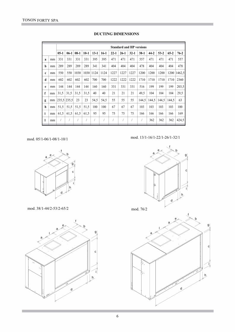
mod. 38/1-44/2-53/2-65/2 mod. 76/2
mod. 05/1-06/1-08/1-10/1 mod. 13/1-16/1-22/1-26/1-32/1
a
c d c
AIR
Ø1 Ø2
Ø3 Ø4
a
b
b
dc c
AIRØ1 Ø2
Ø3 Ø4
a
b
b
dc c
AIR
Ø1 Ø2
Ø3 Ø6 Ø4
Ø5
a
b
b
dc c
AIR
dd
Ø1 Ø2
Ø3 Ø6
Ø5
Ø4
1179,5 1179,5 1179,5
b
b
1056,5 1056,5 1056,5
/ / / / / / / / /
1114,5
125
125
130
130
140
140
165
165
POSITIONING THE BASE SUPPORTS - SPREADING THE WEIGHT
TONON FORTY SPA
6
05-1 06-1 08-1 10-1 13-1 16-1 22-1 26-1 32-1 38-1 44-2 53-2 65-2 76-2
a mm 331 331 331 331 395 395 471 471 471 557 471 471 471 557
b mm 289 289 289 289 341 341 404 404 404 478 404 404 404 478
c mm 550 550 1030 1030 1124 1124 1227 1227 1227 1200 1200 1200 1200 1462,5
d mm
e mm
Standard and HP versions
mod. 38/1-44/2-53/2-65/2 mod. 76/2
mod. 05/1-06/1-08/1-10/1 mod. 13/1-16/1-22/1-26/1-32/1
DUCTING DIMENSIONS
a
d
b
c
e
g
f
h
a
d
b
c
e
g
f
h
i
a
d
b
c
e
g
f
h
a
i
l a
d
b
c
e
g
f
h
a
i
l
f mm
g mm
h mm
i mm
l mm
602 602 602 602 700 700 1222 1222 1222 1710 1710 1710 1710 2360
144 144 144 144 160 160 331 331 331 516 199 199 199 203,5
31,5 31,5 31,5 31,5 40 40 21 21 21 49,5 104 104 104 29,5
i
51,5 51,5 51,5 51,5 100 100 67 67 67 103 103 103 103 100
61,5 61,5 61,5 61,5 95 95 75 75 75 166 166 166 166 169
/ / / / / / / / / / 362 362 362 424,5
235,5 235,5 23 23 54,5 54,5 55 55 55 144,5 144,5 144,5 144,5 63

TONON FORTY SPA
7
FAN SPEED
13-1 16-1 22-1 26-1 32-1 38-1 44-2 53-2 65-2 76-2
Power input kW 1,1 1,5 1,5 3 4 3 2,2 2,2 2,2 3Ø fixed pulley mm 190 170 280 224 224 280 200 200 200 280
mm 88 88 109 109 109 109 109 109 109 109Ø expanding pulley 101 101 121 121 121 121 121 121 121 121
EWR
WORKING CONDITIONSMODEL
EWR / HP
minmedmax
Fan speed
Power inputØ fixed pulley
Ø expanding pulley
WORKING CONDITIONSMODEL
Fan speed
Power inputØ fixed pulley
Ø expanding pulley
WORKING CONDITIONSMODEL
Fan speed
Power inputØ fixed pulley
Ø expanding pulley
WORKING CONDITIONSMODEL
Fan speed
minmedmax
mmmmrpmrpmrpm
13-1 16-1 22-1 26-1 32-1 38-1 44-2 53-2 65-2 76-2
kWmmmmmin
medmaxminmedmax
mmmmrpmrpmrpm
EPR
13-1 16-1 22-1 26-1 32-1 38-1 44-2 53-2 65-2 76-2
kWmmmmmin
medmaxminmedmax
mmmmrpmrpmrpm
EPR / HP
13-1 16-1 22-1 26-1 32-1 38-1 44-2 53-2 65-2 76-2
kWmmmmmin
medmaxminmedmax
mmmmrpmrpmrpm
114 114 133 133 133 133 133 133 133 133644 720 553 691 693 553 774 774 774 553739 826 614 767 770 614 859 859 859 614834 932 675 843 846 675 944 944 944 675
1,1 1,5 2,2 3 4 3 3 3 3 3150 150 224 200 200 250 224 200 200 22488 88 109 109 109 109 109 109 109 109101 101 121 121 121 121 121 121 121 121114 114 133 133 133 133 133 133 133 133815 818 691 774 777 619 691 774 774 619936 939 767 859 862 687 767 859 859 687
1056 1060 843 944 948 755 843 944 944 755
1,1 1,1 2,2 2,2 4 3 2,2 2,2 3 3180 180 250 250 224 280 250 250 224 28088 88 109 109 109 109 109 109 109 109101 101 121 121 121 121 121 121 121 121114 114 133 133 133 133 133 133 133 133680 680 619 619 693 553 619 619 691 553780 780 687 687 770 614 687 687 767 614880 880 755 755 846 675 755 755 843 675
1,5 1,5 3 3 4 4 2,2 2,2 3 4150 150 200 200 200 250 200 224 190 22488 88 109 109 109 109 109 109 109 109101 101 121 121 121 121 121 121 121 121114 114 133 133 133 133 133 133 133 133818 818 774 774 777 621 774 691 815 693939 939 859 859 862 690 859 767 904 770
1060 1060 944 944 948 758 944 843 994 846

TONON FORTY SPA
8
The KAP module is supplied with a pump that guarantees the useful pressure as shown in the enclosed table.
(1) - These device are already installed on the unit in theKAP modules.
The main plumbing diagrams are given on the following page, showing the components installed on the unit and those to be installed i n the field for the standard units and the KAP (storage and pump kit) modules.
MODEL 05-1 06-1 08-1 10-1 13-1 16-1 22-1 26-1 32-1 38-1EWR standard versionWater flow l/s 0,234 0,272 0,401 0,502 0,621 0,736 1,065 1,29 1,58 1,77Pressure drops kPa 3 5 17 25 17 30 21 28 29 46
EWR stamdard versionWater flow l/s 2,05 2,41 2,99 3,54Pressure drops kPa 57 55 50 53
FLOW SWITCH
MODEL 44-2 53-2 65-2 76-2
MODEL 05-1 06-1 08-1 10-1 13-1 16-1 22-1 26-1 32-1 38-1EPR standard versionWater flow l/s 0,263 0,330 0,463 0,549 0,707 0,922 1,24 1,45 1,88 2,10Pressure drops kPa 3 5 17 25 17 30 21 28 29 46
EPR stamdard versionWater flow l/s 2,49 2,88 3,53 4,38Pressure drops kPa 57 55 50 53
MODEL 44-2 53-2 65-2 76-2
3.0 WATER CONNECTIONS
PIPING The system piping may be in steel, galvanised steel,polyethylene or PVC. The size of the pipes should be in relation to the nominalwater flow rate, the system loss of head and thecharacteristics of the circulating or other pump provided forin the system.
In this way the size of the pipes has to be calculated inrelation to the performance of the pump, carefully assessingthe losses of head in the system. All the pipes should be suitably lagged to prevent storage ofheat (with consequent drop in unit efficiency) and formationof condensation on the outer surface. For this purpose use closed-cell insulating material with amin. thickness of 10 mm. To prevent the transmission of vibrations from the unit to theuser system and to compensate for thermal expansion, it is agood rule to install flexible couplings on the pipe fittings ofthe unit. The system should be in compliance with regulations andstandards of the country of installation. In any case it is a good rule to install the following devices toguarantee correct use and maintenance of the appliance. vibration-damping flexible couplingscut-off cockspockets for housing water temperature measuring sensorsmetal mesh filterair vent devicesautomatic efficiency unitdrain cockexpansion tank (1)safety valve (1)flow switch (1)
To guarantee correct operation and performance, each unitrequires a nominal water flow rate as indicated in thefollowing table;Using lower water flow rates could cause malfunctioningwith serious consequences and damage to some componentsof prime importance, such as the compressor and the cooler.
CAUTION
A water flow switch has to be fitted on the water pipingwhen the chiller is of standard type.We suggest to use the electrical consense “Pump on/off”as main regulation for the external mounted pumps.
Technical data table for dimensioning the hydraulic circuit:

TONON FORTY SPA
9
°C 5 2 -3 -10 -15
% 0 10 20 30 40- 1 0.97 0.95 0.93 0.9- 1 0.99 0.98 0.97 0.96- 1 1.02 1.1 1.14 1.3- 1 1.08 1.3 1.39 1.6°C 0 -3 -8 -15 -23
max
15
m
DEPENDING ON THE MODELS AND THE USER’S PLANT LAYOUT, THE MACHINES MUST BE FITTEDWITH A SERIES OF COMPONENTS, THAT HAVE ALREADY BEEN LISTED, TO GUARANTEE THE BESTOPERATIONS FROM THE SYSTEM. HOWEVER, THESE COMPONENTS MUST BE PERIODICALLYCHECKED TO ENSURE THEY ARE STILL OPERATING CORRECTLY.
* PERIODICALLY CHECK THE SAFETY FLOW SWITCH TRIGGERS.* CHECK THE READING ON THE ANTIFREEZE PROBE, AND COMPARE IT WITH A CERTIFIED
INSTRUMENT. IF THE READING IS INCORRECT, THEN THE PROBE MUST BE GAUGED.* PERIODICALLY CLEAN THE MESH FILTER AT THE ENTRANCE TO THE MACHINE HEATEXCHANGER.* CHECK THE PRESSURE IN THE HYDRAULIC PLANT IS WITHIN THE SAFETY LIMITS (MAX 3 bar).
IN NORMAL CONDITIONS, THE HYDRAULIC PRESSURE CAN VARY BETWEEN 0.8 ÷ 1.2 bar.
DIFFERENCE IN LEVEL BETWEEN THE CHILLING UNIT AND THE HIGHEST POINT IN THE SYSTEM
3.1 USING ANTIFREEZE
If the water system is not drained during the winter period ofidleness, it is necessary to mix the water with anti-freeze insuitable percentage parts.
The use of anti-freeze only slightly affects cooling capacity,but causes considerable variation to the water flow rate andloss of head of the system.In these circumstances pump efficiency should bemeticulously checked to prevent malfunctioning and damagewhich would undoubtedly result if the required nominalwater flow rate is not guaranteed.
The table below gives the recommended percentage mixvalues if ethyl glycol is used, in relation to the min.temperature outside the room in which the unit is situated.
The standard pumps installed in theKAP modulecan operate with a maximum of 30% of glycol. Ifthe machine is to be used with mixtures containingmore than 30%, contact TONON S.p.a..
Outside air temperature in winter (appliance off)
Recommended % of ethyl glycol (in weight)Cooling capacity corr. coefficient *Input power corr. coefficient *Water flow rate corr. coefficientCooler loss of head corr. coefficientMix freezing point
* for operation under nominal conditions (ext. air temp. 35°C/cool. water temp. 7°C)

TONON FORTY SPA
10
•
Models 10-1 : 38-1 L1-L2-L3-N-PEModels 44-2 : 76-2 L1-L2-L3-N-PE
•
Models 05-1 : 38-1 2-3Models 44-2 : 76-2 2-3
•
Models 05-1 : 38-1 2-6Models 44-2 : 76-2 2-6
2 3
2 3 4 5 6 2 3 4 5 6
2 3
Models 05-1 : 08-1 L-N-PE
The other units are dimensioned for a power supply of 400V/50Hz + N (neutral lead for auxiliary supply) + Pe.
The Mod. 05-06-08 are dimensioned for a power supply of 230V/50Hz + N (neutral lead for auxiliary supply) + Pe.
/
4.0 ELECTRICAL CONNECTIONS
Rules of a general nature.
All the units are supplied with electric control board with allthe elements necessary for appliance operation and control ofinstalled safety devices.The electrical connections to the unit should be carried out incompliance with CEI regulations in force in Italy or theregulations in force in the country of installation and incompliance with indications given in the wiring diagramenclosed with the appliance.Before carrying out any operation on electrical parts inside oroutside the unit, make sure that it is disconnected from thepower supply.The section of the supply cables should be in relation to thetotal maximum absorbed current. The wiring diagram givesthe recommended sections for installations where there is acircuit breaker with fuses installed near the unit.Earth the appliance properly, using the correspondingterminal inside the electric control board.The supply voltage should be in conformity with unitspecifications (voltage/frequency/No. phases/presence ofneutral wire) and should not be subject to variationsexceeding ± 5% with less than 2% unbalance between thephases (with three-phase power supply).The use of electrical power supply sources not in conformitywith the manufacturer’s instructions could jeopardiseoperation and soundness of the appliance and render thewarranty null and void.
4.1 ELECTRICAL CONNECTIONS
The electrical connections for which the user is responsibleare given on page 01 or 05 of the wiring diagram and may besummed up as follows:
Power supply line connections:
Terminal numbering Q.E.
Remote ON/OFF switch:
Use a clean unpowered contact
Parameter CF16=0Logic: - closed: function disconnected - open: function enabled.
The functioning logics for the digital ON/OFF input can beinverted, modifying the CF16 parameter, in the user sub-menu (see point 12.1).
E.g.:
CF16=0 CF16=1
N.B. the unit can only be turned on and off from thekeyboard if the input is disconnected (priority for theremote control)
Remote Summer/Winter switch:
- This function is only fitted for models with EPRheat pump, and allows installing chiller/heat pump remoteselection.
Use a clean unpowered contact
CF13=0 CF13=1
Functioning logic:With parameter CF13=1 (standard configuration) and remote“open” consent, the machine works with the heat pump, if itis “closed” the chiller works.With parameter CF13=0 and remote “open” consent, themachine works with the “Chiller”, if it is closed the heatpump works.
Contact clouseUnit Heat-pumpfunction
Contact clouseUnit Chiller function
To use the remote summer/winter consent, the CF 28 parameter must be enabled which is found in the User Menu (CF28=1).
TONON FORTY SPA
11
•
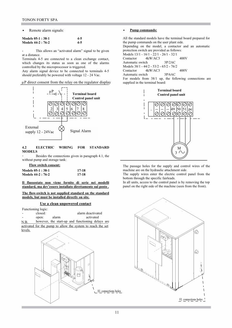
Models 05-1 : 38-1 4-5Models 44-2 : 76-2 4-5
-
Models 05-1 : 38-1 17-18Models 44-2 : 76-2 17-18
Il flussostato non viene fornito di serie nei modellistandard, ma dev’essere installato direttamente sul posto .
•
2 3 4 5 6 7 8
µP
El. connections holes
El. connections holes
Remote alarm signals:
- This allows an “activated alarm” signal to be givenat a distance.Terminals 4-5 are connected to a clean exchange contact,which changes its status as soon as one of the alarmscontrolled by the microprocessor is triggered.Any alarm signal device to be connected to terminals 4-5should preferably be powered with voltage 12 - 24 Vac.
External supply 12 - 24Vac Signal Alarm
µP direct consent from the relay on the regulator display
Terminal boardControl panel unit
4.2 ELECTRIC WIRING FOR STANDARDMODELS
Besides the connections given in paragraph 4.1, thewithout pump and storage tank:
Flow switch consent:
The flow-switch is not supplied standard on the standardmodels, but must be installed directly on site.
Use a clean unpowered contactFunctioning logic:- closed: alarm deactivated- open: alarm activatedN.B. however, the start-up and functioning delays areactivated for the pump to allow the system to reach the setlevels.
M3
Terminal boardControl panel unit
.. -- -- -- 49 50 51 pe
Pump commands:
All the standard models have the terminal board prepared forthe pump commands on the user plant side.Depending on the model, a contactor and an automaticprotection switch are provided as follows:Models 13/1 - 16/1 - 22/1 - 26/1 - 32/1Contactor 4kW/AC3 400VAutomatic switch 3P/2ACModels 38/1 - 44/2 - 53/2 - 65/2 - 76/2Contactor 4kW/AC3 400VAutomatic switch 3P/6ACFor models from 38/1 up, the following connections aresupplied in the terminal board:
The passage holes for the supply and control wires of themachine are on the hydraulic attachment side.The supply wires enter the electric control panel from thebottom through the specific fairleads.In all units, access to the control panel is by removing the toppanel on the right side of the machine (seen from the front).

TO
NO
N FO
RT
Y SPA
12
05-1 06-1 08-1 10-1 13-1 16-1 22-1 26-1 32-1 38-1
1 1 1 1 1 1 1 1 1 1
5,5kW/ac3/400V 7,5kW/ac3/400V 11kW/ac3/400V 11kW/ac3/400V 15kW/ac3/400V
kW 1,61 2,06 2,87 3,36 4,11 5,39 7,6 8,73 10,67 13,25
- - - - -
A 7,5 9,6 13,4 6,15 7,87 10,21 13,92 15,99 18,56 22,32
A 11,4 14,8 23,1 10 13 16 18 21 26 30
A 47 61 100 50 66 101 123 127 167 198
n°
kW 0,515 0,515 0,515 0,515 1,1 1,5 1,5 3 4 3
A 3,8 3,8 3,8 3,8 2,7 3,6 3,6 6,4 8,6 6,4
V 230 230 230 400 400 400 400 400 400 400
Hz 50 50 50 50 50 50 50 50 50 50
n° pH+N+PE pH+N+PE pH+N+PE 3pH+N+PE 3pH+N+PE 3pH+N+PE 3pH+N+PE 3pH+N+PE 3pH+N+PE 3pH+N+PE
V 12 12 12 12 12 12 12 12 12 12
kW 2,125 2,575 3,385 3,875 5,21 6,89 9,1 11,73 14,67 16,25
A 11,3 13,4 17,2 9,95 10,57 13,81 17,52 22,39 27,16 28,72
A 15,2 18,6 26,9 13,8 15,7 19,6 21,6 27,4 34,6 36,4
A 50,8 64,8 103,8 53,8 68,7 104,6 126,6 133,4 175,6 204,4
- 20A/1p/D 20A/1p/D 25A/1p/D 16A/3p/D 16A/3p/D 63A 80A
mmQ
TOTAL CONSUMPTION
FAN SECTION
EWR
44-2 53-2 65-2 76-2
2 2
11kW/ac3/400V 11kW/ac3/400V
kW 7,6 8,75 10,67 13,25
A 13,9 16 18,56 22,3
A 18 21 26 30
A 123 127 167 198
n°
kW 2,2 2,2 2,2 3
A 4,9 4,9 4,9 6,4
V 400 400 400 400
Hz 50 50 50 50
n° 3pH+N+PE 3pH+N+PE 3pH+N+PE 3pH+N+PE
V 12 12 12 12
kW 19,6 21,9 25,74 32,5
A 37,6 41,8 46,92 57,4
A 45,8 51,8 61,8 72,8
A 150,8 157,8 202,8 240,8
- 80A 80A
mmQ
FAN SECTION
EWR
2 2
15kW/ac3/400V4kW/ac3/400V5,5kW/ac3/400V4kW/ac3/400V4kW/ac3/400V
15kW/ac3/400V15kW/ac3/400V
20A/3p/D 25A/3p/D 40A/3p/D40A/3p/D
1 1 1 1 1 1 1 1 1 1
2 2 2 2
25A/3p/D 25A/3p/D 32A/3p/D
2,5 2,5 4 2,5 4 4 6 6 6 16
16 16 25 25
80A 80A
Technical data about pump for Mod. 05-06:
Power rating: 0,09 kW
Rated current: 0,45 A
V / Ph / Hz: 230 / 1 / 50
Technical data about pimp for Mod. 08-10:
Power rating: 0,235 kW
Rated current: 1,02 A
V / Ph / Hz: 230 / 1 / 50
EW
R - T
OT
AL
CO
NSU
MPT
ION
TA
BL
E
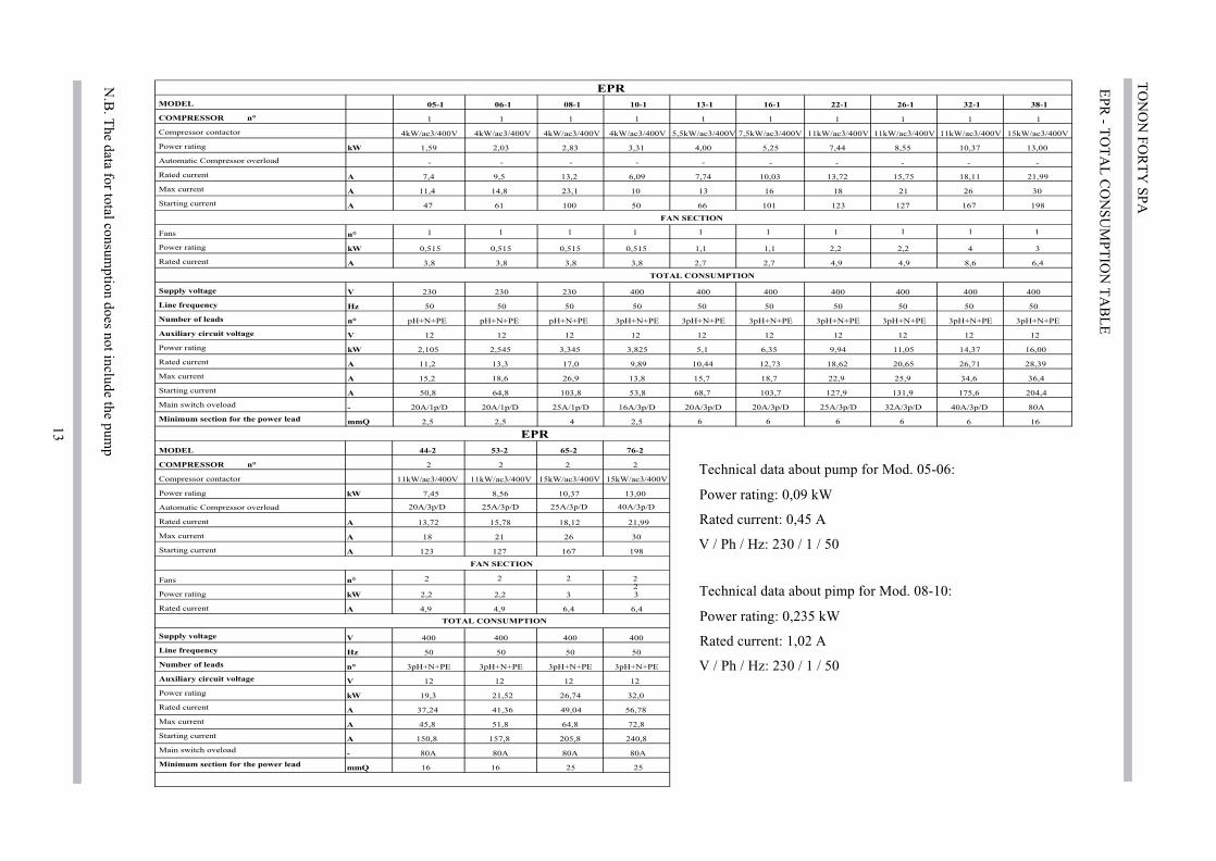
N.B
. The data for total consum
ption does not include the pump
TOTAL CONSUMPTION
MODEL
COMPRESSOR n°
Compressor contactor
Power rating
Automatic Compressor overload
Rated current
Max current
Starting current
Fans
Power rating
Rated current
Supply voltage
Line frequency
Number of leads
Auxiliary circuit voltage
Power rating
Rated current
Max current
Starting current
Main switch oveload
Minimum section for the power lead
TO
NO
N FO
RT
Y SPA
13
05-1 06-1 08-1 10-1 13-1 16-1 22-1 26-1 32-1 38-1
1 1 1 1 1 1
5,5kW/ac3/400V 7,5kW/ac3/400V 11kW/ac3/400V 11kW/ac3/400V 15kW/ac3/400V
kW 1,59 2,03 2,83 3,31 4,00 5,25 7,44 8,55 10,37 13,00
- - - - -
A 7,4 9,5 13,2 6,09 7,74 10,03 13,72 15,75 18,11 21,99
A 11,4 14,8 23,1 10 13 16 18 21 26 30
A 47 61 100 50 66 101 123 127 167 198
n°
kW 0,515 0,515 0,515 0,515 1,1 1,1 2,2 2,2 4 3
A 3,8 3,8 3,8 3,8 2,7 2,7 4,9 4,9 8,6 6,4
V 230 230 230 400 400 400 400 400 400 400
Hz 50 50 50 50 50 50 50 50 50 50
n° pH+N+PE pH+N+PE pH+N+PE 3pH+N+PE 3pH+N+PE 3pH+N+PE 3pH+N+PE 3pH+N+PE 3pH+N+PE 3pH+N+PE
V 12 12 12 12 12 12 12 12 12 12
kW 2,105 2,545 3,345 3,825 5,1 6,35 9,94 11,05 14,37 16,00
A 11,2 13,3 17,0 9,89 10,44 12,73 18,62 20,65 26,71 28,39
A 15,2 18,6 26,9 13,8 15,7 18,7 22,9 25,9 34,6 36,4
A 50,8 64,8 103,8 53,8 68,7 103,7 127,9 131,9 175,6 204,4
- 20A/1p/D 20A/1p/D 25A/1p/D 16A/3p/D 20A/3p/D 80A
mmQ
EPR
44-2 53-2 65-2 76-2
2 2
11kW/ac3/400V 11kW/ac3/400V
kW 7,45 8,56 10,37 13,00
A 13,72 15,78 18,12 21,99
A 18 21 26 30
A 123 127 167 198
n°
kW 2,2 2,2 3 3
A 4,9 4,9 6,4 6,4
V 400 400 400 400
Hz 50 50 50 50
n° 3pH+N+PE 3pH+N+PE 3pH+N+PE 3pH+N+PE
V 12 12 12 12
kW 19,3 21,52 26,74 32,0
A 37,24 41,36 49,04 56,78
A 45,8 51,8 64,8 72,8
A 150,8 157,8 205,8 240,8
- 80A 80A
mmQ
EPR
2 2
11kW/ac3/400V4kW/ac3/400V4kW/ac3/400V4kW/ac3/400V4kW/ac3/400V
15kW/ac3/400V15kW/ac3/400V
20A/3p/D 25A/3p/D 40A/3p/D25A/3p/D
1 1 1 1 1 1 1 1 1 1
2 2 2 2
20A/3p/D 25A/3p/D 32A/3p/D
2,5 2,5 4 2,5 6 6 6 6 6 16
16 16 25 25
80A 80A
1 1 1 1
- - - - -
40A/3p/D
2
Technical data about pump for Mod. 05-06:
Power rating: 0,09 kW
Rated current: 0,45 A
V / Ph / Hz: 230 / 1 / 50
Technical data about pimp for Mod. 08-10:
Power rating: 0,235 kW
Rated current: 1,02 A
V / Ph / Hz: 230 / 1 / 50
EPR
- TO
TA
L C
ON
SUM
PTIO
N T
AB
LE
N.B
. The data for total consum
ption does not include the pump
MODEL
COMPRESSOR n°
Compressor contactor
Power rating
Automatic Compressor overload
Rated current
Max current
Starting current
Fans
Power rating
Rated current
Supply voltage
Line frequency
Number of leads
Auxiliary circuit voltage
Power rating
Rated current
Max current
Starting current
Main switch oveload
Minimum section for the power lead
TOTAL CONSUMPTION
FAN SECTION
FAN SECTION
TOTAL CONSUMPTION

TONON FORTY SPA
14
13-1
16-1
22-1
26-1
32-1
38-1
11
11
1
5,5
kW
/ac3
/40
0V
7,5
kW
/ac3
/40
0V
11
kW
/ac3
/40
0V
11
kW
/ac3
/40
0V
15
kW
/ac3
/40
0V
kW
4,1
15
,39
7,6
8,7
31
0,6
71
3,2
5
-
A7
,87
10
,21
13
,92
15
,99
18
,56
22
,32
A1
31
61
82
12
63
0
A6
61
01
12
31
27
16
71
98
n°
kW
1,1
1,5
2,2
34
3
A2
,73
,64
,96
,48
,66
,4
V4
00
40
04
00
40
04
00
40
0
Hz
50
50
50
50
50
50
n°
3p
H+
N+
PE
3p
H+
N+
PE
3p
H+
N+
PE
3p
H+
N+
PE
3p
H+
N+
PE
3p
H+
N+
PE
V1
21
21
21
21
21
2
kW
5,2
16
,89
9,8
11
,73
14
,67
16
,25
A1
0,5
71
3,8
11
8,8
22
2,3
92
7,1
62
8,7
2
A1
5,7
19
,62
2,9
27
,43
4,6
36
,4
A6
8,7
10
4,6
12
7,9
13
3,4
17
5,6
20
4,4
-16A
/3p/D
80
A
mm
Q
EW
R /
HP
15
kW
/ac3
/40
0V
11
11
11
20A
/3p/D
25A
/3p/D
32A
/3p/D
44
66
61
6
13-1
16-1
22-1
26-1
32-1
38-1
1
5,5
kW
/ac3
/40
0V
7,5
kW
/ac3
/40
0V
11
kW
/ac3
/40
0V
11
kW
/ac3
/40
0V
15
kW
/ac3
/40
0V
kW
4,0
05
,25
7,4
48
,55
10
,37
13
,00
-
A7
,74
10
,03
13
,72
15
,75
18
,11
21
,99
A1
31
61
82
12
63
0
A6
61
01
12
31
27
16
71
98
n°
kW
1,5
1,5
33
44
A3
,63
,66
,46
,48
,68
,6
V4
00
40
04
00
40
04
00
40
0
Hz
50
50
50
50
50
50
n°
3p
H+
N+
PE
3p
H+
N+
PE
3p
H+
N+
PE
3p
H+
N+
PE
3p
H+
N+
PE
3p
H+
N+
PE
V1
21
21
21
21
21
2
kW
5,5
6,7
51
0,4
41
1,5
51
4,3
71
7,0
0
A1
1,3
41
3,6
32
0,1
22
2,1
52
6,7
13
0,5
9
A1
6,6
19
,62
4,4
27
,43
4,6
38
,6
A6
9,6
10
4,6
12
9,4
13
3,4
17
5,6
20
6,6
-20A
/3p/D
80
A
mm
Q
EP
R /
HP
11
kW
/ac3
/40
0V
11
11
11
20A
/3p/D
25A
/3p/D
32A
/3p/D
66
66
61
6
11
11
--
--
-
40A
/3p/D
44-2
53-2
65-2
76-2
22
11
kW
/ac3
/40
0V
11
kW
/ac3
/40
0V
7,6
8,7
51
0,6
71
3,2
5
13
,91
61
8,5
62
2,3
18
21
26
30
12
31
27
16
71
98
33
33
6,4
6,4
6,4
6,4
40
04
00
40
04
00
50
50
50
50
3p
H+
N+
PE
3p
H+
N+
PE
3p
H+
N+
PE
3p
H+
N+
PE
12
12
12
12
21
,22
3,5
27
,34
32
,5
40
,64
4,8
49
,92
57
,4
48
,85
4,8
64
,87
2,8
15
3,8
16
0,8
20
5,8
24
0,8
80A
80A
22
15
kW
/ac3
/40
0V
15
kW
/ac3
/40
0V
20
A/3
p/D
25
A/3
p/D
40
A/3
p/D
40
A/3
p/D
22
22
16
16
25
25
80A
80A
44-2
53-2
65-2
76-2
22
11
kW
/ac3
/40
0V
11
kW
/ac3
/40
0V
7,4
58
,56
10
,37
13
,00
13
,72
15
,78
18
,12
21
,99
18
21
26
30
12
31
27
16
71
98
2,2
2,2
34
4,9
4,9
6,4
8,6
40
04
00
40
04
00
50
50
50
50
3p
H+
N+
PE
3p
H+
N+
PE
3p
H+
N+
PE
3p
H+
N+
PE
12
12
12
12
19
,32
1,5
22
6,7
43
4,0
37
,24
41
,36
49
,04
61
,18
45
,85
1,8
64
,87
7,2
15
0,8
15
7,8
20
5,8
24
5,2
80A
80A
22
15
kW
/ac3
/40
0V
15
kW
/ac3
/40
0V
20
A/3
p/D
25
A/3
p/D
40
A/3
p/D
25
A/3
p/D
22
22
16
16
25
25
80A
80A
--
--
-
1
40A
/3p/D
EWR/HP - EPR/HP - TOTAL CONSUMPTION TABLEM
OD
EL
CO
MP
RE
SS
OR
n
°
Co
mp
ress
or
con
tact
or
Pow
er r
atin
g
Auto
mat
ic C
om
pre
ssor
over
load
Rat
ed c
urr
ent
Max
curr
ent
Sta
rtin
g c
urr
ent
Fan
s
Pow
er r
atin
g
Rat
ed c
urr
ent
Su
pp
ly v
olt
age
Lin
e fr
equ
ency
Nu
mb
er o
f le
ad
s
Au
xil
iary
cir
cuit
volt
age
Pow
er r
atin
g
Rat
ed c
urr
ent
Max
curr
ent
Sta
rtin
g c
urr
ent
Mai
n s
wit
ch o
vel
oad
Min
imu
m s
ecti
on
for
the
pow
er l
ead
MO
DE
L
CO
MP
RE
SS
OR
n
°
Co
mp
ress
or
con
tact
or
Pow
er r
atin
g
Au
tom
atic
Co
mp
ress
or
ov
erlo
ad
Rat
ed c
urr
ent
Max
curr
ent
Sta
rtin
g c
urr
ent
Fan
s
Pow
er r
atin
g
Rat
ed c
urr
ent
Su
pp
ly v
olt
age
Lin
e fr
equ
ency
Nu
mb
er o
f le
ad
s
Au
xil
iary
cir
cuit
volt
age
Pow
er r
atin
g
Rat
ed c
urr
ent
Max
curr
ent
Sta
rtin
g c
urr
ent
Mai
n s
wit
ch o
vel
oad
Min
imu
m s
ecti
on
for
the
pow
er l
ead
TO
TA
L C
ON
SU
MP
TIO
N
FA
N S
EC
TIO
N
TO
TA
L C
ON
SU
MP
TIO
N
FA
N S
EC
TIO
N

prgprg
prgprg
M SETSET
M SETSET
TONON FORTY SPA
15
m.a.Ch.m.a.Ch.
°C
bar
1 2
Z ZZ
H
L
Flow !Flow !
MenuMenu
M SETSET
prgprg12.312.3C̊
1 2
36.5m.a.Ch.
m.a.Ch.
5.0 USE
MICROPROCESSOR CONTROL DEVICE
All the units are fitted with microprocessor control device designed to control all thecharacteristic parameters essential for applianceoperation.
5.1 USER INTERFACE
The instrument display is divided into three areas.Left Upper Area:It shows user system water IN / OUT temperature.IN - inlet water temperature (return from user system)OUT - outlet water temperature (delivery to usersystem)Left Lower Area:It shows condensation temperature / pressure or theactive time (function activated on call as anaccessory).Right Area: Signalling icons.
5.2 DISPLAY ICONS
The display icons give some general informations as forthe following description:
Degrees Celsius This icon explains the value showned on the disply is aTemperature (° C)
BarThis icon explains the value showned on the disply is aPressure (Bar)
Compressor 1 / 2This icon explains the compressor statusFlashing: Compressor 1 / 2 enabled. Timing inprocess.Fixed Compressor 1 / 2 running
Unit on Stand_byAs well as the unit is switched ON or OFF, the Stand-bymode is enabled and the correspondent icon lights.
Even if the Stand-by mode is enabled, the regulatorallows the following:1) Temperature sensors reading
2) Alarm code reading3) Antifreeze el. heaters control
Alarm Genericit signals the presence of one or more alarms. In case of auto-resetting alarm, access the M key function menu and selectthe “AlrM” function.
Alarm High Pressureit signals that an alarm has been triggered by the highpressure safety pressure switch. The safety device isconnected to ID3 digital input. (see the applicable wiringdiagram).
Alarm Low Pressure
it signals that an alarm has been triggered by the low pressuresafety pressure switch. The safety device is connected to ID4digital input. (see the applicable wiring diagram).
Heater antifreezeHeater antifreeze on
Alarm Flow Switch.
it signals that an alarm has been triggered by the safety waterflow switch. The safety device is connected to ID1 digitalinput. (see the applicable wiring diagram).
Defrosting Start Count Down time /Clock
Maintenance required
Compressor running time limit over. Service required
Menu
“Menu Funzioni” enabled
5.3 KEY FUNCTIONS
The M key allows to access function menuand time set-up.
The SET key allows to display or change theset point value. In programming mode, itselects a parameter or confirms a value.
Keeping this key pressed for 5 sec will startor stop the unit in either cooling (chiller) orheating (H.P.) mode of operation. It selectswater IN/OUT temperatures on the upperdisplay. In programming mode, it scrollsthrough parameters codes or increases theirvalue.
Keeping this key pressed for 5 sec will startthe unit in either cooling (chiller) or heating(H.P.) mode of operation.It selects outside airtemperature / defrost display. Inprogramming mode, it scrolls throughparameters codes or increases their value.
ENGLISH

TONON FORTY SPA
16
M SETSET
prgprg
M SETSET
prgprg
M SETSET
prgprg
•
•
M SETSET
prgprg18.518.5C̊
1 2
Outm.a.Ch.
m.a.Ch.
M SETSET
prgprg12.312.3C̊
1 2
Inm.a.Ch.
m.a.Ch.
M SETSET
prgprg18.518.5C̊
A07m.a.Ch.
m.a.Ch.
M SETSET
prgprg12.312.3C̊
1 2
36.5m.a.Ch.
m.a.Ch.
M SETSET
prgprg-11.6-11.6C̊
1 2
dEFm.a.Ch.
m.a.Ch.
5.4 COMBINED KEY FUNCTIONS
To access programming mode
To exit programming mode.
Pressing and holding these keys for morethan 5 sec will start a manual defrostcycle.
5.5 FRONT PANEL SYMBOLS AND LEDS
Symbol LED Function
On Unit ON in heat pump
On Unit ON in chiller
BlinkingDuring programming
phase (it blinks togetherwith a LED )
Blinking Defrost Start Delay Time
On Defrost active
OffDefrost disabled or
finished
Time Clock set-up
6.0 DISPLAY6.1 STANDARD DISPLAY
In normal conditions, the following are displayed:Top display:Intake water temperature (user plant recycle); outlet watertemperature (user plant delivery).Bottom display:condensation temperature or pressure, with relative unit ofmeasure.Current time (optional on request).
6.2 DISPLAY DURING ALARMS
Varying from a normal condition (no alarm active), as soonas an alarm condition is detected, the instrument alternatelyshows blinking alarm code and respective icon, andtemperature / pressure on the lower display (example givenin the fig.: presence of alarm high pressure).
6.3 QUICK DISPLAY OF MAININFORMATION
In order to help user during the machine test-and-check phase, the procedure for displaying maininformation without accessing selection menu hasbeen simplified.
Pressing the key will display inrotation system delivery and return temperatures. Thisfunction helps to check the actual evaporator inlet/outletthermal head, which should corresponds approximately to5°C in normal working conditions.
Pressing the keywill display in rotation outside air temperatures (probeavailable as optional) / and condensation or defrosttemperatures (heat-pump unit).
ENGLISH

TONON FORTY SPA
17
Z ZZ
Z ZZ
Z ZZ
M SETSET
prgprg18.518.5C̊
36.5m.a.Ch.
m.a.Ch. ZZZ
5 sec.
M SETSET
prgprg18.518.5C̊
36.5m.a.Ch.
m.a.Ch. 1
5 sec.
M SETSET
prgprg18.518.5C̊
36.5m.a.Ch.
m.a.Ch. 1
M SETSET
prgprgOFFOFF
m.a.Ch.
m.a.Ch.
7.0 UNIT ON STAND-BY
Stand-by mode is enabled any time the unit is turned off,either in chiller or in p.d.c. mode of operation. When the unit
is in stand-by mode, the icon will light up.Also in stand-by mode, the controller allows to:1) Display the detected measuraments2) Menage alarm events by displaying and signalling them.3) Activate heating elements as evaporator anti-freeze
safety device depending on thermoregulator.E’ possibile passare dalla modalità chiller alla modalitàOnly by turning off the unit will it be possible to switchfrom chiller to heat-pump mode of operation.
7.1 ACTIVATING/DEACTIVATING THECHILLING FUNCTION (SUMMER MODE)
When you press the key for five seconds, the unitgoes from stand-by to chiller and vice versa. When the delaytime is up, if no alarms are active, the compressors areactivated in sequence. During the ignition phase, the stand-by
icon is turned off, while the sun led is alightshowing the chiller mode. During the chiller operations, onlythe relative set-point can be changed (“StC” set chiller), orthe dynamic set can be displayed if it is activated (“StD”).
7.2 ACTIVATING/DEACTIVATING HEATINGFUNCTION (WINTER MODE)
When you press the key for five seconds the unitgoes from stand-by to heat pump “h.p.” and vice versa. Whenthe delay time is up, if no alarms are active, the compressors
are activated. During the ignition phase, the stand-by icon
is turned off, while the snow led , is alight showing theheat pump function. During the heat pump operations, onlythe relative set-point can be changed (“StH” Set heat pump)or the dynamic set can be displayed if it is activated (“StD”).
7.3 ACTIVATING/DEACTIVATING FROM THEDIGITAL INPUT
This can be used if you want to control the activation anddeactivation of the machine from the remote control, e.g.from the clock (see paragraph 4.1 on page 6).
USE A CLEAN UNPOWERED CONTACT
1. It has priority over the keyboard2. The unit can only be turned on and off from the
keyboard if the input is deactivated.3. When the digital input is deactivated, the instrument
returns to the previous state.The top display shows “OFF ” with the tenths led flashingN.B. the polarity of the id5 input can be inverted, sothat with the signal activated the unit is ON. Theparameter to fix this function is CF16=1 which can bedirectly changed by the user (see the paragraph access tothe user menu).
7.4 CONTROLLING THE CHILLER / HEATPUMP FUNCTIONS FROM THE DIGITALINPUT
To use the remote summer/winter consent, the CF 28parameter must be enabled which is found in the UserMenu (CF28=1). Once the parameter has been activated,the selection has priority from the remote control.With the CF28=1 activated, if the unit is running in Chiller orHeat pump and the functioning mode needs changing, thecontroller turns off all the outlets (compressor, pump, etc.)waits for a certain delay time, which is shown by the chilleror heat pump led flashing. The flashing led shows thefunctioning mode that unit will be turned back on to,respecting the protection time delay for the compressors.
ENGLISH

TONON FORTY SPA
18
8.3
•
SEt.D summer functioning logic (chiller)
With pB4 > = Sd04 SEt.D = SEt.CWith pB4 < = Sd04 – Sd06 SEt.D = SEt.C + Sd02
Sd04 – Sd06 Sd04
SEt.C + Sd02
SEt.C
• SEt.D winter functioning logic (heat pump)
With pB4 > = Sd05 SEt.D = SEt.HWith pB4 < = Sd05 + Sd07 SEt.D = SEt.H + Sd03
Sd05 Sd05+ Sd07
SEt.H + Sd03
SEt.H
pB4
pB4
M SETSET
prgprg12.512.5C̊
SEtCm.a.Ch.
m.a.Ch.
5 sec.
1
M SETSET
M SETSET
prgprg10.010.0C̊
SEtCm.a.Ch.
m.a.Ch. 1
M SETSET
prgprg10.010.0C̊
SEtCm.a.Ch.
m.a.Ch. 1
M SETSET
prgprg38.538.5C̊
SEtHm.a.Ch.
m.a.Ch.
5 sec.
1
M SETSET
prgprg43.043.0C̊
SEtHm.a.Ch.
m.a.Ch. 1
M SETSET
prgprg43.043.0C̊
SEtHm.a.Ch.
m.a.Ch. 1
M SETSET
prgprg37.237.2C̊
SEtdm.a.Ch.
m.a.Ch. 1
ENGLISH
8.0 SETTING THE “SET POINT”
8.1 SEt.C Set point Chiller 12.5°C
When the SET key is pressed with the unit on stand-by orchiller functions, the set value can be displayed. To changethe set point, press the SET key for about 5 seconds, afterwhich the displayed value starts flashing, now use the UP andDOWN keys to change the value within the limits that havebeen set in the factoryST05 10°C set summer minimumST06 18°C set summer maximum
The value flashes, the arrow keysare used to change the value.
When the SET key is pressedthe changed value is memorised
8.2 SEt.H Set point heat pump 38.5°C
When the SET key is pressed with the unit on stand-by orheat pump functions, the set value can be displayed. Tochange the set point, press the SET key for about 5 seconds,after which the displayed value starts flashing, now use theUP and DOWN keys to change the value within the limitsthat have been set in the factory.
ST07 36°C set winter minimumST08 43°C set winter maximum
The value flashes, the arrow keysare used to change the value.
When the SET key is pressedthe changed value is memorised
8.3 SEt.D Dynamic set-point (optional onrequest)
This allows changing the set-point depending on thetemperature that is read by the optional pB4 external probe.In this way the performance of the compressor is improvedC.O.P., consenting energy savings.With the dynamic set-point activated, when the SET keyis pressed a second time the bottom display shows the“Set.D” label (dynamic set), and the top display shows theeffective set value the machine is working with.(The SETd label is only activated if the dynamic set-point isenabled). The parameters to regulate the dynamic control inchiller and heat pump functions can be directly set from theuser menu, with the following formulas:
Sd02 Increase maximum dynamic set-point in chillerfunction. Establishes the maximum variation for the set-pointin chiller mode.Sd04 Set external air temperature, dynamic set point inchiller mode.Sd06 Temperature difference between external air anddynamic set-point in chiller mode.
Sd03 Increase maximum dynamic set-point in heat pumpfunction. Establishes the maximum variation for the set-pointin heat pump mode.Sd05 Set external air temperature, dynamic set point in heat-pump mode.Sd07 Temperature difference between external air anddynamic set-point in chiller mode.

TONON FORTY SPA
19
•
•
•
E.g.:CF16=0 CF16=1
CF29
Chiller
P.d.C.
CF30 Pb4
2 3 2 3
8.4 SEt.S Energy saving (Optional on request)
Energy Saving funtion allows to run two differentworking set points in both chiller/ heat-pump modes of operation.It could be programmed daily or weekly by time bands(version with on-board time clock, on-request accessory), orrun by external contact. During an Energy Saving cycle, theset point is increased by the value set in ES10 / ES12, so thatthe working set point will become SET+ES10 in chillermode of operation, or SET+ES12 in heat pump mode ofoperation. The referring differential for thermoregulationwith active energy saving will correspond to the value of S11parameter in chiller mode of operation, ES13 parameter inheat pump mode of operation.
E.S. Daily Programming(Only for models with on-board time clock.Optional on request)
Set the energy saving parameter relating to the day to 1.E.g.: ES03 = 1 (energy saving active on Monday, 24 hour aday).Set parameters from ES04 to ES09 to 1 to enable energysaving during all the other days of the week.
Time Band Programming(Only for models with on-board time clock.Optional on request)
Set the parameter ES01 (Energy Saving cycle start time),ES02 (Energy Saving cycle stop time).E.g.: ES01 = 8.0 ES02 = 10.0 energy saving active 8÷10.0all days of the week.E.g.: ES01 = 23.0 ES02 = 8.0 energy saving active from11.00 P.M. to 8.00 A.M. of the following day, all days of theweek. The time band function will be prohibited ifparameters ES01 / ES02 are set to the same time or to 0.
• Running from External Contact
The E.S. function can always be run directly from id5external contact. To enable this function, set the parameterCF10=8.
N.B. The functioning logics for the digital E.S. inputcan be inverted, modifying the CF16 parameter, in theuser sub-menu (see point 12.1)..
Use a clean unpowered contact
Contact closedEnergy saving active
Contact closedEnergy saving notactivated
• Energy Saving ParametersES01 Energy saving start timeES02 Energy saving stop timeES03 Monday0 = disabled1= enabledES04 Tuesday0 = disabled1= enabledES05 Wednesday0 = disabled1= enabledES06 Thursday0 = disabled1= enabledES07 Friday0 = disabled1= enabledES08 Saturday0 = disabled1= enabledES09 Sunday0 = disabled1= enabledES10 Energy saving setting increase in chiller mode of
operationES11 Energy saving differential in chiller mode of
operationES12 Energy saving setting increase in heat pump mode
of operationES13 Energy saving differential in heat pump mode of
operation8.5 AUTOMATIC CHANGE-OVER
(Optional on request)
It automatically changes the unit state of functioning(chiller / heat pump) according to programming andexternal climatic conditions.The change-over can occur only if the models are heat-pumpsEPA, with sensor ambient optional Pb4.Parameters governing the change over function:CF29 It allows to set the change over set point, which isthe value of the PB4-detected temperature below which theinstrument will force a p.d.c. mode of operation.CF30 It allows to set the change over differential, whichis the temperature differential depending on which theinstrument will force a chiller mode of operation.In order to help user set up the change over set point, pressingand releasing the arrow key will display the temperatureof PB4 probe for 5sec on the upper display, while the lowerdisplay will show the Et label.Change-Over Regulator Chart
For temperatures within the CF30 differential, changeover via keypad is allowed.
ENGLISH

TONON FORTY SPA
20
Ewa - Epa
On
Alarm
OnOff
Com
mon
On
Ala
rmW
in/S
um12
/24
Vac
12/2
4 V
ac
2 3 4 5 6 7 8
Com
mon
On
Ala
rmW
in/S
um12
/24
Vac
12/2
4 V
ac
12v/24v
18.518.5C̊
36.5
1
setset menmenù
m.a.Ch.m.a.Ch.
37.237.2 C̊
SEtd
1
setset menmenù
m.a.Ch.m.a.Ch.
58
72100
64
1024
70
55
83.5
40
9.0 BASIC REMOTE CONTROL PANELKRCbase (Optional on request)
This panel allows ON/OFF control for all the EWA and EPAunits. If a EPA unit which can be inverted to heat pumpfunction is involved, it allows switching over the functioningmode, from chiller to heat pump and vice versa. It alsosignals if an alarm is active in the machine with a red ledlighting up. Once the electric wiring is complete, as shownbelow, check that the jumper on the right side of the electricterminal board is closed (12Vac power supply). If thejumper is not correctly positioned it can damage theremote control.
N.B. Change the CF16 = 1 parameter so that theactivation logic respects that of the remote control. Theparameter can be changed directly from the user menu,see paragraph 12.1.
COMMANDS1. ON/OFF switch2. Summer/Winter switchDISPLAY3 Green led On4 Green led Summer5 Green led Winter6 Red led AlarmMEASUREMENTS- 120 x 70 x 28.7 mm
ENGLISH
9.1 ELECTRIC CONNECTIONS FOR THE KRCBASIC REMOTE CONTROL PANEL
The electric connections between the remote control paneland the electric control board on the unit must be made onsite, using a 6-pole cable with a minimum section of 0.5sq.mm. The maximum recommended length must no exceed150 meters.The electric connections to the remote control panel are thefollowing:
Rear view of the remotecontrol panel
Jumper closed12 Vac power supply
Unit electric controlpanel terminal
board
Krc basic remotecontrol panel
10.0 TOP REMOTE CONTROL PANEL KRCtop (Optional on request)
Provided as an on-request accessory, this kit allows to displayand run all control parameters displayed as from machinecontroller. The keypad size enables the device to be installedwithin the very common (3 modules) wall boxes used in civilelecrtical systems. The remote terminal must be mounted onthe panel, or on a 72x56 mm hole, and fixed using screws.

TONON FORTY SPA
21
figure 2
2 3 4 5 6 7 8 9 10
+ -1 2
KRC Top
Max 80mt
setsetmenmenù
m.a.Ch.m.a.Ch.
PVC box for outdoor installation
Gasket for IP65 protection
Krc top remote control panel
Covering flap
menmenù
setset
M SETSET
prgprg37.237.2C̊
12.0m.a.Ch.
m.a.Ch. 1
To obtain a IP65 front protection, use the front protectionrubber, mod. RGW-V (optional). For external fixing on wall,a V-KIT vertical keypad adapter, as the one shown in figure2, is available.
10.1 FUNCTION OF THE KRC Top KEYS
The M key allows to access function menuand time set-up.
The SET key allows to display or change theset point value. In programming mode, itselects a parameter or confirms a value.This key allows to select water IN/OUTtempreatures, on the upper display. Inprogramming mode, it scrolls throughparameter codes or increase their values.This key allows to display outside air /defrost temperature.In programming mode, it scrolls throughparameter codes or decrease their values.Keeping this key pressed for 5 sec will startor stop the unit in either chiller or heat pumpmode of operation.Keeping this key pressed for 5 sec will startor stop the unit in either chiller or heat pumpmode of operation
10.2 ELECTRIC CONNECTIONS FOR THE KRCTop
El. Wiring between the unit switchboard and the remotecontrol panel have to be done using a 2 way……………… 0,5 mmq size. The Max suggested lenghtis 80 m. Over this lenght the wire size have to beincreased up tp 1,5 mmq for a 150 m max lenght.Connection wire is NOT included on the KRCaccessory
ELECTRIC CONTROL PANEL
11.0 “ M KEY ” FUNTION MENU
Accessing function menu will allow to:1) Display and reset triggered alarms2) Display and reset controlled load working hours3) Enable the control via infrared transmission (supplied as
an accessory)4) Display the remaning time before defrost start (only if
the unit is configured as heat-pump)5) Tansfer parameters from the instrument to the key (see
point ----)6) Display alarm history7) Delete alarm history (While the function menu is displayed, the “menu” iconis lit up).
11.1 ACCESS TO THE “M” FUNCTION MENU
Press and release the
M (menu) key. The “menu” icon willappear.
11.2 EXIT FROM THE FUNCTION MENU
Press and release the M key or wait for time-out (15s). The“menu” icon will disappear.
11.3 - HOW TO DISPLAY AND RESETALARMS
The system runs about 30 alarm codes. The mostimportant ones are displayed by means of icons at thesides of the two displays. All the alarms can be identifiedthrough a code, and stored, up to 50, in time wise order..
Access function menu:
1) By using the keys, select the “ALrM” function.2) Press and release the SET key.3) By using the keys, scroll through all the alarms.To exit, press the menu key or wait 15s for time-out.
Rear view of theKrc Top controlpanel
ENGLISH
TONON FORTY SPA
22
M SETSET
prgprg
ALrMm.a.Ch.
m.a.Ch. 1
M SETSET
prgprg37.237.2C̊
10.5m.a.Ch.
m.a.Ch. 1
M SETSET
prgprgrStrSt
A01m.a.Ch.
m.a.Ch.
H
M SETSET
prgprg
ALrMm.a.Ch.
m.a.Ch.
M SETSET
prgprg
ALoGm.a.Ch.
m.a.Ch. 1
M SETSET
prgprgn 01n 01
A01m.a.Ch.
m.a.Ch. 1
M SETSET
prgprgn 02n 02
A07m.a.Ch.
m.a.Ch. 1
M SETSET
prgprgPASPAS
ArStm.a.Ch.
m.a.Ch. 1
M SETSET
prgprg --- ---
PASm.a.Ch.
m.a.Ch. 1
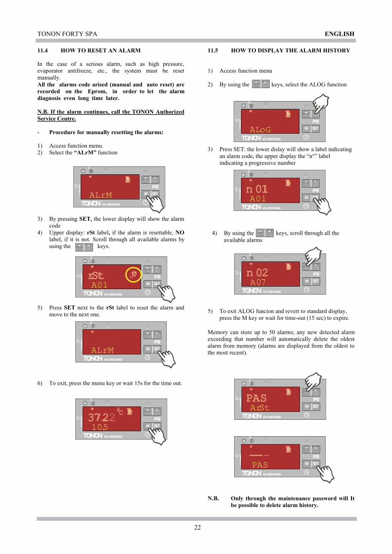
11.4 HOW TO RESET AN ALARM
In the case of a serious alarm, such as high pressure,evaporator antifreeze, etc., the system must be resetmanually.All the alarms code arised (manual and auto reset) arerecorded on the Eprom, in order to let the alarmdiagnosis even long time later.
N.B. If the alarm continues, call the TONON AuthorizedService Centre.
- Procedure for manually resetting the alarms:
1) Access function menu.2) Select the “ALrM” function
3) By pressing SET, the lower display will show the alarmcode
4) Upper display: rSt label, if the alarm is resettable, NOlabel, if it is not. Scroll through all available alarms byusing the keys.
5) Press SET next to the
rSt label to reset the alarm andmove to the next one.
6) To exit, press the menu key or wait 15s for the time out.
11.5 HOW TO DISPLAY THE ALARM HISTORY
1) Access function menu
2) By using the keys, select the ALOG function
3) Press SET: the lower dislay will show a label indicatingan alarm code, the upper display the “n°” labelindicating a progressive number
4) By using the keys, scroll through all theavailable alarms
5) To exit ALOG funcion and revert to standard display,press the M key or wait for time-out (15 sec) to expire.
Memory can store up to 50 alarms; any new detected alarmexceeding that number will automatically delete the oldestalarm from memory (alarms are displayed from the oldest tothe most recent).
N.B. Only through the maintenance password
will Itbe possible to delete
alarm history.
ENGLISH
TONON FORTY SPA
23
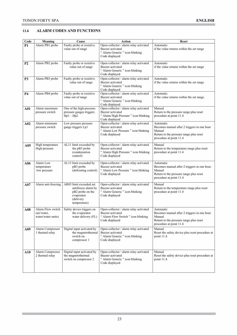
Code Meaning Cause Action ResetP1 Alarm PB1 probe Faulty probe or resistive
value out of rangeOpen-collector / alarm relay activatedBuzzer activated“ Alarm Generic ” icon blinkingCode displayed
Automaticif the value returns within the set range
P2 Alarm PB2 probe Faulty probe or resistivevalue out of range
Open-collector / alarm relay activatedBuzzer activated“ Alarm Generic ” icon blinkingCode displayed
Automaticif the value returns within the set range
P3 Alarm PB3 probe Faulty probe or resistivevalue out of range
Open-collector / alarm relay activatedBuzzer activated“ Alarm Generic ” icon blinkingCode displayed
Automaticif the value returns within the set range
P4 Alarm PB4 probe Faulty probe or resistivevalue out of range
Open-collector / alarm relay activatedBuzzer activated“ Alarm Generic ” icon blinkingCode displayed
Automaticif the value returns within the set range.
A01 Alarm maximumpressure switch
One of the high-pressurepressure gauges triggersHp1 – Hp2
Open-collector / alarm relay activatedBuzzer activated“ Alarm High Pressure ” icon blinkingCode displayed
ManualReturn to the pressure range plus resetprocedure at point 11.4
A02 Alarm minimumpressure switch
Low pressure pressuregauge triggers Lp1
Open-collector / alarm relay activatedBuzzer activated“ Alarm Low Pressure ” icon blinkingCode displayed
AutomaticBecomes manual after 2 triggers in one hourManualReturn to the pressure range plus resetprocedure at point 11.4
High temperatureHigh pressure
AL11 limit exceeded bythe pB3 probe(condensationcontrol)
Open-collector / alarm relay activatedBuzzer activated“ Alarm High Pressure ” icon blinkingCode displayed
ManualReturn to the temperature range plus resetprocedure at point 11.4
A06 Alarm Lowtemperature low pressure
AL13 limit exceeded bypB3 probe(defrosting control)
Open-collector / alarm relay activatedBuzzer activated“ Alarm Low Pressure ” icon blinkingCode displayed
AutomaticBecomes manual after 2 triggers in one hour.ManualReturn to the pressure range plus resetprocedure at point 11.4
A07 Alarm anti-freezing AR03 limit exceeded setantifreeze alarm bypB2 probe on theevaporator(deliverytemperature)
Open-collector / alarm relay activatedBuzzer activated“ Alarm Generic ” icon blinkingCode displayed
ManualReturn to the temperature range plus resetprocedure at point 11.4
A08 Alarm Flow switch(air/water,water/water units)
Safety device triggers onthe evaporatorwater delivery (FL)
Open-collector / alarm relay activatedBuzzer activated“ Alarm Flow Switch ” icon blinkingCode displayed
AutomaticBecomes manual after 2 triggers in one hourManualReturn to the pressure range plus resetprocedure at point 11.4
A09 Alarm Compressor1 thermal relay
Digital input activated bythe magnetothermalswitch oncompressor 1
Open-collector / alarm relay activatedBuzzer activated“ Alarm Generic ” icon blinkingCode displayed
ManualReset the safety device plus reset procedure atpoint 11.4.
A10 Alarm Compressor2 thermal relay
Digital input activated bythe magnetothermalswitch on compressor 2
Open-collector / alarm relay activatedBuzzer activated“ Alarm Generic ” icon blinkingCode displayed
ManualReset the safety device plus reset procedure atpoint 11.4.
11.6 ALARM CODES AND FUNCTIONS
ENGLISH
A05

TONON FORTY SPA
24
ENGLISH
A11 AlarmCondensation fanthermal relay
Digital input activated bythe fan thermal switch(thermal and klixon)
Open-collector / alarm relay activatedBuzzer activated“ Alarm Generic ” icon blinkingCode displayed
ManualReset the safety device plus reset procedure atpoint 11.4.
A12Alarm DefrostError
End of defrosting fordF07 (maximumtime)
Code displayedOnly signalling
AutomaticBy a subsequent correct defrostManual
A13 AlarmCompressor 1maintenance
Compressor 1 functioninghours exceeded
Open-collector / alarm relay activatedBuzzer activated“ Alarm Maintenance ” icon blinkingCode displayed
ManualWorking hour reset point 11.9
A14 AlarmCompressor 2maintenance
Compressor 2 functioninghours exceeded
Open-collector / alarm relay activatedBuzzer activated“ Alarm Maintenance ” icon blinkingCode displayed
ManualWorking hour reset point 11.9
A15
AlarmWater pumpmaintenance
Working hours > CO16 Open-collector / alarm relay activatedBuzzer activated“ Alarm Maintenance ” icon blinkingCode displayed
ManualWorking hour reset point 11.9
rtC Alarm Time Clock Time Clock to be set Open-collector / alarm relay activatedBuzzer activated“ Alarm Generic ” icon blinkingCode displayed
ManualClock setting plus reset procedure point 11.4
rtF Alarm Time Clock Time Clock faultClock malfunctioning
Open-collector / alarm relay activatedBuzzer activated“ Alarm Generic ” icon blinkingCode displayed
ManualReset procedure point 11.4If after resetting the alarm re-occurs, changethe clock
EE Alarm Eepromerror
Loos in the data stored Open-collector / alarm relay activatedBuzzer activated“ Alarm Generic ” icon blinkingCode displayed
Reset procedure point 11.4If after resetting the alarm re-occurs, thedevice will remain blocked
ACF1
AlarmConfiguration
Unit configured as p.d.c.with non-configuredreversal valve
Open-collector / alarm relay activatedBuzzer activated“ Alarm Generic ” icon blinkingCode displayed
AutomaticBy correct reprogramming
ACF2
AlarmConfiguration
Air/air air/water unitswithout probe configuredfor condensation control
Open-collector / alarm relay activatedBuzzer activated“ Alarm Generic ” icon blinkingCode displayed
AutomaticBy correct reprogramming
ACF3
AlarmConfiguration
Two digital inputs havingthe same configuration
Open-collector / alarm relay activatedBuzzer activated“ Alarm Generic ” icon blinkingCode displayed
AutomaticBy correct reprogramming
ACF4
AlarmConfiguration
CF28= 1 and digital inputnon-configured or CF28=2 probe PB4 other than 3
Open-collector / alarm relay activatedBuzzer activated“ Alarm Generic ” icon blinkingCode displayed
AutomaticBy correct reprogramming
AFr Alarm Supplymains frequency
Mains supply frequencyout of range
Open-collector / alarm relay activatedBuzzer activated“ Alarm Generic ” icon blinkingCode displayed
AutomaticWhen frequency returns within working range

TONON FORTY SPA
25
M SETSET
M SETSET
prgprg 12 12
C1Hrm.a.Ch.
m.a.Ch. 1
M SETSET
prgprg 0 0
C1Hrm.a.Ch.
m.a.Ch. 1 3 sec
11.7 OUTPUT BLOCK TABLE
Alarmcode
Alarm description Comp.1 Comp.2Anti-freezeheatingelements
Pump Cond. fan boiler
P1 Probe PB1 OFFOFF Si
con Ar19 =0OFF OFF
P2 Probe PB2 OFFOFF Si
con Ar19 =0OFF OFF
P3 Probe PB3 OFFOFF Si
con Ar19 =0OFF OFF
P4 Probe PB4 OFFOFF Si
con Ar19 =0OFF OFF
A01 Maximum pressure switch OFF OFFA02 Minimum pressure switch OFF OFF OFFA05 High temperature High pressure OFF OFFA06 Low pressure Low temperature OFF OFF OFFA07 Anti-freeze OFF OFF OFFA08 Flow switch OFF OFF Res. Boiler
OFFOFF
OFF
A09 Compressor 1 thermal relay OFF OFFA10 Compressor 2 thermal relayA11 Condensation fan thermal relay OFF OFF OFFA12 Defrost errorA13 Compressor 1 maintenanceA14 Compressor 2 maintenanceA15 Delivery fan water pump
maintenancertC Alarm Time clockRtF Alarm Time clockEE Error Eeprom OFF OFF OFF OFF OFF OFFACF1 Alarm Configuration OFF OFF OFF OFF OFF OFFACF2 Alarm Configuration OFF OFF OFF OFF OFF OFFACF3 Alarm Configuration OFF OFF OFF OFF OFF OFFACF4 Alarm Configuration OFF OFF OFF OFF OFF OFFAFr Alarm Configuration OFF OFF OFF OFF OFF OFF
11.8 DISPLAY OF LOAD WORKING HOURS
1) Access function menu
2) Press the keys until the lower display shows thelabel of the single load; C1Hr (compressor 1 workinghours), CHr2 (compressor 2 working hours), PFHr(system water pump working hours).
The upper display will show the working hours.
The icon is lit up.
11.9 RESET OF LOAD WORKING HOURS
1) Access function menu
2) Press the keys until the lower display shows thelabel of the single load (C1Hr, C2Hr, PFHr) and theupper display shows the working hours.
3) Keep the SET key pressed for 3 sec:
the upper display will show 0, which means the resethas been carried out correctly.
3) Exit function menu by pressing the M key or waitingfor exit time-out to expire (15s)
4) Repeat operations 1 to 4 for other loads.
Before to reset this Alarm code, a check by theauthorized Service is suggested in order to avoidsubsequents troubles rise.
ENGLISH

26
3)
M SETSET
prgprgALLALL
m.a.Ch.
m.a.Ch. 1
5sec
M SETSET
prgprg37.237.2C̊
10.5m.a.Ch.
m.a.Ch. 1
M SETSET
prgprg CF CF
m.a.Ch.
m.a.Ch. 1
M SETSET
prgprg 1 1
m.a.Ch.
m.a.Ch. 1
CF 16
M SETSET
prgprg 1 1
m.a.Ch.
m.a.Ch.
CF 16
ZZZ
M SETSET
prgprg 0 0
m.a.Ch.
m.a.Ch.
CF 16
ZZZ
12.0 SUB-MENU SELECTION
The regulator parameters are managed underFamily Labels. This system allows a quicker access tothe requird parameter.
LABEL MEANING
ALL Display all the parameters
ST Display only thermoregulation parameters
CF Displays only configuration parameters
SD Display only dynamic set point parameters
ES Display only energy saving parameters
CO Display only compressor parameters
FA Display only ventilation parameters
Ar Display only heating element parameters
DF Display only defrost parameters
AL Display only alarm parameters
12.1 TO ACCESS “PR1” PARAMETERS(USER-LEVEL)
To access the user-accessible “pr1” parameter menu:
1) Keep the SET + keys pressed for few seconds. (and will start blinking); the upper display will show“ALL”, the first family of parameters.
2) Select the different families of parameters by using the keys.
After selecting the family, by pressing the SET key, theinstrument will display label and code of the firstparameter included into the family in “Pr1” on the lowerdisplay, and its value on the upper display.
It will now be possible to scroll and change only theparameters included into that family.
12.2 TO CHANGE PARAMETER VALUES
1. Access programming mode
2. Select the desired parameter.
3. Press the SET key to allow the value to be changed.
4. Change the value by using the keys
5. Press “SET” to store the new value and move to thenext parameter.
6. TO EXIT PROGRAMMING MODE:
Press SET + , when a parameter is displayed, or wait(15s) without pressing any key.
N.B.: The new set value is stored also in case of time-outexit without pressing SET.
12.3 SEQUENCE OF KEYS TO CHANGE THEPARAMETERS
1) Press SET + arrow UP, to access the user menu"PR1"
2) Press the keys , select the rangeof parameters to display (e.g. CF is theconfigurationparameter)
3) Press SET to access the parameters of theselected range.
4) Press SET to select the set value to be changedN.B. this is only possible with the uniton stand-by
5) Press to change the parameter.Press SET to save the change.
ENGLISH

TONON FORTY SPA
27
St01 = 12,5°COn_C1
Off _C1
Pb1
St02 = 3°C
St03 = 38,5°COn_C1
Off _C1
Pb1
St04 = 3°C
St01 = 12,5°C St09 = 3°C
On_C2On_C1
Off_C2
Off _C1
St02 = 3°C St02 = 3°C Pb1
St09 = 3°C St03 = 38,5°C
On_C2
Off_C2
On_C1
Off_C1
Pb1
St04 = 3°C St04 = 3°C
13.0 COMPRESSOR REGULATIONS IN“Chiller” or “Heat-Pump” MODE OF
OPERATION
All the units are controlled depending on temperaturedetected by pB1 probe located at the evaporator inlet(temperature returning from user system). Thecompressors functioning is set out below:
Unit single compressor (Models 051 ÷ 151)
St01 summer set pointSt02 summer differentialC1 Compressor 1Pb1 regolator sensor
Unit single compressor (Models 051 ÷ 151)
St03 winter set pointSt04 winter differentialC1 Compressor 1Pb1 regolator sensor
Unit two-compressors (Models 092 ÷ 152)
St01 summer set pointSt02 summer differentialSt09 compressor 1 /2 regulation bandC1 Compressor 1C2 Compressor 2Pb1 regulation probe
Unit two-compressors (Models 092 ÷ 152)
St03 winter set pointSt04 winter differentialSt09 compressor 1 /2 regulation bandC1 Compressor 1C2 Compressor 2Pb1 regulation probe
13.1 OPERATING MODE FOR THECIRCULATION PUMP
The plant circulation pump functions are controlled by themachine regulator. For the standard versions without storagetank and pump, in the electric control panel terminal boardthere is the on/off consent which interfaces with an externalpower relay (see the electric connections paragraph 4.2).
13.2 TIMING
To guarantee a correct machine functioning and avoiduntimely triggering of some safety devices during compressorstarting and stopping phase. In the regulation system thefollowing timings are active:CO02 360secMinimum Off-time.It determines the time during which the compressor must staydeactivated, even when there is a call for it to restart. Duringthis phase, the LED relating to the compressor is blinking.CO03 10secDelay On-time between the two compressors.It determines starting delay between the two compressors, inorder to reduce the electrical inputs at each starting. Duringthis phase, the LED relating to the compressor is blinking.CO05 60secDelay on-time meant as actual power supply to the control.It delays the activation of outputs in order to distribute mainselectrical inputs and protect the compresor/s against repeatedstartings in case of frequent mains power supply failures.CO07 250secDelay off-time between water pump and compressor.The water pump will be stopped only as machine stops (unitin stand by).
ENGLISH
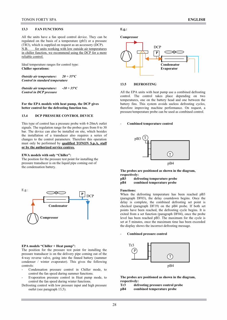
TONON FORTY SPA
28
E.g.:
E.g.:
P
Condensator
Compressor
DCP
Compressor
P
CondensatorEvaporator
DCP
pB4
pB3 T
T
pB4
Tr3
P
T
0,00,20,40,60,81,0
13.3 FAN FUNCTIONS
All the units have a fan speed control device. They can beregulated on the basis of a temperature (pb3) or a pressure(TR3), which is supplied on request as an accessory (DCP).N.B. for units working with low outside air temperaturesin chiller function, we recommend using the DCP for a morereliable control.
Ideal temperature ranges for control type:Chiller operations:
Outside air temperature: 20 ÷ 35°CControl in standard temperature
Outside air temperature: -10 ÷ 35°CControl in DCP pressure
For the EPA models with heat pump, the DCP givesbetter control for the defrosting function too.
13.4 DCP PRESSURE CONTROL DEVICE
This type of control has a pressure probe with 4-20mA outletsignals. The regulation range for the probes goes from 0 to 30bar. The device can also be installed on site, which besidesthe installation of a transducer also requires a series ofchanges to the control parameters. Therefore this operationmust only be performed by qualified TONON S.p.A, staffor by the authorized service centres.
EWA models with only “Chiller”:The position for the pressure test point for installing thepressure transducer is on the liquid pipe coming out ofthe condensation battery.
EPA models “Chiller + Heat pump”:The position for the pressure test point for installing thepressure transducer is on the delivery pipe coming out of the4-way reverse valve, going into the finned battery (summercondenser / winter evaporator). This gives the followingcontrols:- Condensation pressure control in Chiller mode, to
control the fan speed during summer functions.- Evaporation pressure control in Heat pump mode, to
control the fan speed during winter functions.Defrosting control with low pressure input and high pressure
outlet (see paragraph 13,5).
13.5 DEFROSTING
All the EPA units with heat pump use a combined defrostingcontrol. The control takes place depending on twotemperatures, one on the battery head and one between thebattery fins. This system avoids useless defrosting cycles,therefore improving machine performance. On request, apressure/temperature probe can be used as combined control.
- Combined temperature control
The probes are positioned as shown in the diagram,respectively:pB3 defrosting temperature probepB4 combined temperature probe
Functions:When the defrosting temperature has been reached pB3(paragraph DF03), the delay countdown begins. Once thedelay is complete, the combined defrosting set point ischecked (paragraph DF19) on the pB4 probe. If both setpoints have been reached, the defrosting cycle begins. It isexited from a set function (paragraph DF04), once the probelevel has been reached pB3. The maximum for the cycle isset at 5 minutes, once the maximum time has been exceededthe display shows the incorrect defrosting message.
- Combined pressure control
The probes are positioned as shown in the diagram,respectively:Tr3 defrosting pressure control probepB4 combined temperature probe
ENGLISH
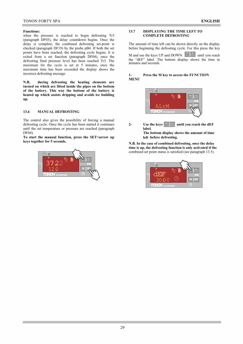
TONON FORTY SPA
29
M SETSET
prgprg37.237.2C̊
12.0m.a.Ch.
m.a.Ch. 1
M SETSET
prgprgC̊
ALrMm.a.Ch.
m.a.Ch. 1
M SETSET
prgprgdEFdEFC̊
30:00m.a.Ch.
m.a.Ch. 1
Functions:when the pressure is reached to begin defrosting Tr3(paragraph DF03), the delay countdown begins. Once thedelay is complete, the combined defrosting set-point ischecked (paragraph DF19) by the probe pB4. If both the setpoints have been reached, the defrosting cycle begins. It isexited from a set function (paragraph DF04), once thedefrosting final pressure level has been reached Tr3. Themaximum for the cycle is set at 5 minutes, once themaximum time has been exceeded the display shows theincorrect defrosting message
N.B. during defrosting the heating elements areturned on which are fitted inside the pipes on the bottomof the battery. This way the bottom of the battery isheated up which assists dripping and avoids ice buildingup.
13.6 MANUAL DEFROSTING
The control also gives the possibility of forcing a manualdefrosting cycle. Once the cycle has been started it continuesuntil the set temperature or pressure are reached (paragraphDF04).To start the manual function, press the SET+arrow upkeys together for 5 seconds.
13.7 DISPLAYING THE TIME LEFT TOCOMPLETE DEFROSTING
The amount of time left can be shown directly on the displaybefore beginning the defrosting cycle. For this press the key
M and use the keys UP and DOWN until you reachthe “dEF” label. The bottom display shows the time inminutes and seconds.
1- Press the M key to access the FUNCTIONMENU
2- Use the keys until you reach the dEFlabel.The bottom display shows the amount of timeleft before defrosting.
N.B. In the case of combined defrosting, once the delaytime is up, the defrosting function is only activated if thecombined set point status is satisfied (see paragraph 13.5).
ENGLISH
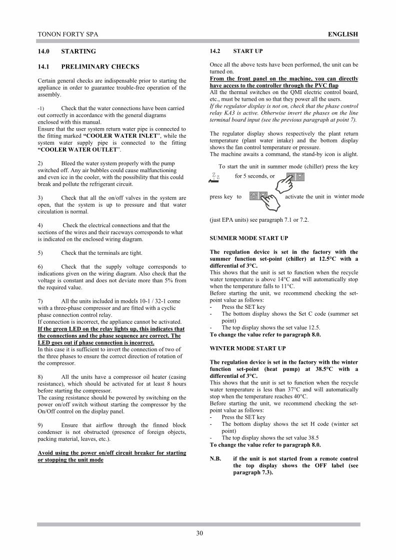
TONON FORTY SPA
30
ZZZ
14.0 STARTING
14.1 PRELIMINARY CHECKS
Certain general checks are indispensable prior to starting theappliance in order to guarantee trouble-free operation of theassembly.
-1) Check that the water connections have been carriedout correctly in accordance with the general diagramsenclosed with this manual.Ensure that the user system return water pipe is connected tothe fitting marked “COOLER WATER INLET”, while thesystem water supply pipe is connected to the fitting“COOLER WATER OUTLET”.
2) Bleed the water system properly with the pumpswitched off. Any air bubbles could cause malfunctioningand even ice in the cooler, with the possibility that this couldbreak and pollute the refrigerant circuit.
3) Check that all the on/off valves in the system areopen, that the system is up to pressure and that watercirculation is normal.
4) Check the electrical connections and that thesections of the wires and their raceways corresponds to whatis indicated on the enclosed wiring diagram.
5) Check that the terminals are tight.
6) Check that the supply voltage corresponds toindications given on the wiring diagram. Also check that thevoltage is constant and does not deviate more than 5% fromthe required value.
7) All the units included in models 10-1 / 32-1 comewith a three-phase compressor and are fitted with a cyclicphase connection control relay.If connection is incorrect, the appliance cannot be activated.If the green LED on the relay lights up, this indicates thatthe connections and the phase sequence are correct. TheLED goes out if phase connection is incorrect.In this case it is sufficient to invert the connection of two ofthe three phases to ensure the correct direction of rotation ofthe compressor.
8) All the units have a compressor oil heater (casingresistance), which should be activated for at least 8 hoursbefore starting the compressor.The casing resistance should be powered by switching on thepower on/off switch without starting the compressor by theOn/Off control on the display panel.
9) Ensure that airflow through the finned blockcondenser is not obstructed (presence of foreign objects,packing material, leaves, etc.).
Avoid using the power on/off circuit breaker for startingor stopping the unit mode
14.2 START UP
Once all the above tests have been performed, the unit can beturned on.From the front panel on the machine, you can directlyhave access to the controller through the PVC flapAll the thermal switches on the QMI electric control board,etc., must be turned on so that they power all the users.If the regulator display is not on, check that the phase controlrelay KA3 is active. Otherwise invert the phases on the lineterminal board input (see the previous paragraph at point 7).
The regulator display shows respectively the plant returntemperature (plant water intake) and the bottom displayshows the fan control temperature or pressure.The machine awaits a command, the stand-by icon is alight.
To start the unit in summer mode (chiller) press the key
for 5 seconds, or
press key to activate the unit in winter mode
(just EPA units) see paragraph 7.1 or 7.2.
SUMMER MODE START UP
The regulation device is set in the factory with thesummer function set-point (chiller) at 12.5°C with adifferential of 3°C.This shows that the unit is set to function when the recyclewater temperature is above 14°C and will automatically stopwhen the temperature falls to 11°C.Before starting the unit, we recommend checking the set-point value as follows:- Press the SET key- The bottom display shows the Set C code (summer set
point)- The top display shows the set value 12.5.To change the value refer to paragraph 8.0.
WINTER MODE START UP
The regulation device is set in the factory with the winterfunction set-point (heat pump) at 38.5°C with adifferential of 3°C.This shows that the unit is set to function when the recyclewater temperature is less than 37°C and will automaticallystop when the temperature reaches 40°C.Before starting the unit, we recommend checking the set-point value as follows:- Press the SET key- The bottom display shows the set H code (winter set
point)- The top display shows the set value 38.5To change the value refer to paragraph 8.0.
N.B. if the unit is not started from a remote controlthe top display shows the OFF label (seeparagraph 7.3).
ENGLISH
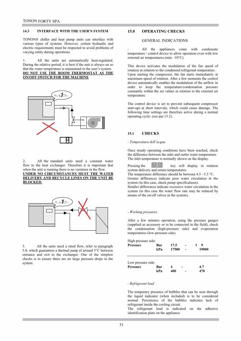
TONON FORTY SPA
31
m.a.Ch.
m.a.Ch.
14.3 INTERFACE WITH THE USER’S SYSTEM
TONON® chiller and heat pump units can interface withvarious types of systems. However, certain hydraulic andelectric requirements must be respected to avoid problems ofvarying entity during operations.
1. All the units are automatically heat-regulated.During the relative period, it is best if the unit is always on sothat the water temperature is maintained in the user’s system.DO NOT USE THE ROOM THERMOSTAT AS THEON/OFF SWITCH FOR THE MACHINE
2. All the standard units need a constant waterflow to the heat exchanger. Therefore it is important thatwhen the unit is running there is no variation in the flow.UNDER NO CIRCUMSTANCES MUST THE WATERDELIVERY AND RECYCLE LINES ON THE UNIT BEBLOCKED.
3. All the units need a rated flow, refer to paragraph3.0, which guarantees a thermal jump of around 5°C betweenentrance and exit to the exchanger. One of the simplestchecks is to ensure there are no large pressure drops in thesystem.
15.0 OPERATING CHECKS
GENERAL INDICATIONS
- All the appliances come with condensatetemperature / control device to allow operation even with lowexternal air temperatures (min. -10°C).
This device activates the modulation of the fan speed ofrotation in relation to the condensed refrigerant temperature.Upon starting the compressor, the fan starts immediately atmaximum speed of rotation. After a few moments the controldevice automatically enables the modulation of the airflow inorder to keep the temperature/condensation pressureconstantly within the set values in relation to the external airtemperature.
The control device is set to prevent subsequent compressorstart-ups at short intervals, which could cause damage. Thefollowing time settings are therefore active during a normaloperating cycle: (see par.13.2).
15.1 CHECKS
- Temperatura dell’acqua
Once steady operating conditions have been reached, checkthe difference between the inlet and outlet water temperature.The inlet temperature is normally shown on the display.
Pressing the key will display in rotationsystem delivery and return temperatures.The temperature difference should be between 4.5 - 5.5 °C.Greater differences indicate poor water circulation in thesystem (in this case, check pump specifications).Smaller differences indicate excessive water circulation in thesystem (in this case the water flow rate may be reduced bymeans of the on/off valves in the system).
- Working pressures
After a few minutes operation, using the pressure gauges(supplied as accessory or to be connected in the field), checkthe condensation (high-pressure side) and evaporationtemperatures (low-pressure side).
High pressure side:Pressure Bar 17.5 - 1 9
kPa 17500 - 19000
Low pressure side:Pressure Bar 4 - 4.7
kPa 400 - 470
- Refrigerant load
The temporary presence of bubbles that can be seen throughthe liquid indicator (when included) is to be considerednormal. Persistence of the bubbles indicates lack ofrefrigerant inside the cooling circuit.The refrigerant load is indicated on the adhesiveidentification plate on the appliance.

TONON FORTY SPA
32
- Presence of humidity
After a few hours of operation, check the colour of the crowninside the liquid level indicator (when included):- a somewhat yellow colour indicates the presence ofhumidity in the cooling circuit. In this case, have qualifiedpersonnel remove the moisture from the circuit.
- Overheating temperature of the refrigerant gas
This value corresponds to the difference between thetemperature of the gas measured on the intake pipe and thetemperature of evaporation measured on the pressure gauge.For optimal appliance performance, the values should bebetween 4 and 10 °C.
- Under-cooling temperature of the refrigerant liquid
This value corresponds to the difference between thetemperature of condensation measured on the pressure gaugeand the temperature measured on the liquid pipe.For optimal appliance performance, the values should exceed2-3 °C.
- Electrical input
Check that electrical input corresponds to the values given onthe technical data sheet.
15.2 CONTROL AND SAFETY DEVICES
All the appliances are fitted with a control device and a seriesof safety components, as listed on the following pagesThese devices are calibrated in the factory and checkedduring the final test prior to dispatch.Once the appliance has been installed and after a reasonableperiod of operation, it is a good rule to check the efficiency ofthe control/safety devices and that the calibration valuesgiven in the following tables correspond.
Safety devices
safety device set point differenzial
Antifreeze 4°C 3°Cthermostat
- alarm activation temperature: set point- reenabling temperature: set point + differential
High pressurePressostat 24Bar 6Bar
2400kPa 600kPa
- alarm activation temperature: set point- reenabling temperature: set point - differential
Low pressurePressostat 2Bar 1Bar
200kPa 100kPa
- alarm activation temperature: set point- reenabling temperature: set point + differential
Overload compressor 1,33 x I nom. comp.
The antifreeze alarm and high pressure, are manual reseting.Before resetting the unit after lock out (refer to paragraph11.4), check the reason for the problem. If the alarmcontinues contact the TONON® Authorised service centrewho will provide the necessary maintenance.
16.0 MAINTENANCE
16.1 GENERAL INFORMATION
Before leaving the factory all the machines arecarefully tested and left running for a sufficient period toensure that all components work properly and that all thecontrol and safety devices trigger correctly.
After correct installation no further adjustmentsneed to be made unless repairs are carried out ormalfunctioning occurs.
It is, however, indispensable to periodically checkthat the appliance is working correctly, especially afterprolonged periods of idleness.
This maintenance should be carried out by qualifiedpersonnel TONON® only, following the instructions givenin this manual.
The maintenance operations described on thefollowing pages should be considered as routine and areextremely important for the quality of operation and for longlife of the appliance.
A troubleshooting list is given at the end of thechapter, in which possible troubles that could be encounteredare listed, plus the corresponding causes and remedies.
16.2 PERIODIC MAINTENANCE ANDCHECKS
Monthly checks.
- Check the working pressures on the high and low pressureside using a common pressure gauge unit or, if provided, thepressure gauges installed on the appliance. Rated working pressures:
External air temperature: 35°CHigh pressure side: Bar 18,5
kPa 1850
Water temperature : 12-7 °CLow pressure side: Bar 4,2
kPa 420
Check the safety devices work correctly, and thatthe set trigger levels correspond as given in paragraph 15.2.
Check the refrigerant load through the liquid indicatorinstalled on all the appliances. If bubbles can be seen throughthe indicator under steady operating conditions, this indicatespossible lack of refrigerant.Also check the colour of the crown inside the liquid indicator.Any tendency towards yellow indicates the presence ofmoisture or humidity and the filter should therefore be
TONON FORTY SPA
33
replaced. If the problem persists, dehydrate the coolingcircuit.
Check the oil level in the compressor sump (frommodel 22/1).After a few hours operations, the level shouldsettle slightly below the middle line on the inspectionwindow.
Check the total consumptions correspond to thelevels give on the electrical data table.
Check that the liquid circuit is properly filled,carefully bleeding the circuit through suitable air valves toeliminate any remaining air bubbles.
-Check that the electric terminals inside the electriccontrol board and on the external user devices are tight.
Six-monthly maintenance checks
- Carry out all maintenance operations scheduled atmonthly intervals.
- Check that the condenser unit is clean. If necessaryclean the fins using compressed air blown in the oppositedirection to the airflow or, if there is concentrated clogging, ajet of water at moderate pressure.
- Check that the noise and vibration levels of themoving parts (compressor/fan/pump) are within normallimits.
16.3 STOPPING FOR THE SEASON
The EWR range of water coolers are normally used in civiltype air-conditioning systems which remain idle during thewinter.
If the appliance is installed in areas where there is thepossibility of freezing during winter, the system must bedrained of water or the latter mixed with anti-freezesolutions in suitable percentage parts. In this caseappliance efficiency may be slightly affected and the sizeof the pump should be calculated taking intoconsideration the variation in the parameters of waterflow rate and loss of head of the cooler (see table 3.0).
N.B. FOR UNITS WITH EVAPORATORANTIFREEZE ELEMENTS, DO NOT TURN THEPOWER OFF TO THE UNIT TO AVOID THE SAFETYDEVICE BEING TURNED OFF DURING COLDPERIODSThe antifreeze elements are active even when the unit ison stand-by.
16.4 SAFETY INFORMATION
All maintenance, repairs and replacement operations to anycomponent, adding refrigerant gas, dismantling the unit, mustall be done by qualified personnel trained in air conditioningunits.
Electric connectionsFit a differential automatic switch near to the unit, withadequate capacity for the electric intake.Connect the unit to earth, checking it is efficient.
Refrigerant fluidsThe type of refrigerant to use is given on the technical dataplate on the hydraulic attachment side of the unit.The lubrication oil to use is given on the compressor plate.
WarningsIf the refrigerant gas accidentally leaks, take the followingprecautions:- if the refrigerant gas comes into contact with skin or eyes, itcan cause frostbite. Therefore, use protective gloves andclothing, and protect the face and eyes.Prolonged inhalation of refrigerant gas can causeunconsciousness or heart disorders. Elevated concentrationscan cause asphyxia due to the lack of oxygen in thesurrounding atmosphere.- Never use open flames, which due to combustion can causetoxic substances.
16.5 DEMOLISHING THE MACHINE AND DISPOSING OF TOXIC SUBSTANCES.
Demolition and processing of the substances used in themachine must be entrusted to authorised persons, inaccordance with legislation in force. Harmful substances likecompressor oil and refrigerant, must not be emptied directlyinto the atmosphere, but collected in special containers anddelivered to the special disposal centres. all the identificationplates and technical documents must be destroyed.

TONON FORTY SPA
34
17.0 FAULT SEEKING
FAULT SYMPTOM PROBABLE CAUSE REMEDY
Power supply failure.
Check the electric wiring to themain power terminals and checkthe voltage levels.Check the fuses on the secondaryside of the auxiliary transformer.
The display panel does notlight up
Inverted phases. The KA3 phasecontrol relay does not giveconsent. Alarm led not active.
Invert the phases into the electriccontrol terminal board,
The display panel comes onbut the appliance does notstart.
Unit on STAND-BYrefer to paragraph 7.0 to start upthe machine.
The display panel comes on,the on/off control is activatedbut the appliance does notstart.
Lack of externalacknowledgement.
Check the connections to externalacknowledgement terminals 2-3.If unused, a jumper should beconnected between the terminals.
The appliance does not startand the comp. LED on thedisplay panel blinks.
Time setting in progress.Wait for the time setting to elapse(max. 360 sec.), after which thecompressor should start.
The appliance doesnot start.
The control panel displayblinks indicating one or morealphanumeric codesalternating with thetemperature value.
One or more safety devicestriggered.
Check which safety device hastriggered, eliminate the cause forthe alarm and reset the safetydevice (see the list of alarm codesparagraph 11.6)
Normal operation, stops andstarts too frequent due toactivation of the low-pressurepressure switch.
Lack of refrigerant.Identify and eliminate therefrigerant leak and refill.
The compressorcontinuously stopsand starts again.
Intake pressure too low andrime on filter.
Clogged filter. Replace the filter.
Temperature too high in theair-conditioned environment. Excessive heat load. Check infiltration and insulation.
Temperature too low in theair-conditioned environment.
The thermostat trips with too lowa temperature.
Recalibrate or repair thethermostat.
The compressorcontinues to operate;it never stops.
Bubbles on refrigerant flowindicator. Lack of refrigerant.
Identify and eliminate therefrigerant leak and refill.
The compressor “knocks”.Broken compressor internal parts. Overhaul the compressor.
Return of liquid.Check overheating and theposition of the expansion valvebulb.
The compressor isnoisy The intake piping is
abnormally cold.Expansion valve locked in theopen position.
Repair or replace the expansionvalve.

TONON FORTY SPA
35
FAULT SYMPTOM PROBABLE CAUSE REMEDY
The thermostatic valvewhistles.
Vaporisation of liquid refrigerant. Add refrigerant.
Difference in temperature inthe refrigerant pipe around thefilter or the expansion valve.
Clogged filter or solenoid valve. Clean or replace.
Intermittent or interruptedoperation.
Locked or obstructed expansionvalve.
Repair or replace.
Badly adjusted overheating.Repair the expansion valve andcheck overheating.
System efficiency islower than normal.
Excessive overheating.
Excessive drop in pressure in thecooler.
Check overheating and recalibratethe expansion valve.
Insufficient condensation airflow.
Check fan conditions and checkfor airflow obstruction.
Cold air at capacitor outlet.
Dirty capacitor.Remove the material clogging thecapacitor (leaves, paper, etc.)
Delivery pressuretoo high.
Air at capacitor outlet too hot.Circuit too full of refrigerant;capacitor partially flooded.
Remove refrigerant from thecapacitor.
The compressor continues tooperate; it never stops
Excessive charge to the cooler.Check that external air infiltrationinto the air-conditionedenvironment is not excessive
Overfed expansion valve.Adjust the degree of overheatingand check the bulb position.
Intake piping too cold
Return of liquid tocompressor Expansion valve locked in the
open position.Repair or replace the valve.
Intake pressure toohigh.
Noisy compressor.Faulty compressor compressioncoils.
Overhaul the compressor.
17.0 FAULT SEEKING

TONON FORTY SPA ENGLISH
36
1204,5
EWR - EPR
13-1* 1"1/4 1"1/4
16-1* 1"1/4 1"1/4
22-1 1"1/4 1"1/4
26-1 1"1/4 1"1/4
32-1 1"1/4 1"1/4
EWR - EPR
38-1* 1"1/4 1"1/4
44-2 2" 2"
53-2 2" 2"
65-2 2" 2"
EWR - EPR
76-2 2" 2"
EWR - EPR
08-1 3/4" 3/4"
10-1 3/4" 3/4"
EWR - EPR
Ø1 Ø2
05-1 3/4" 3/4"
06-1 3/4" 3/4"
1176 605
449
100,5
167
20
847
1204,5
605
449
100,5167
20
111
4,5
1176
1460 (1120*) 780
251
470
785 (
655,5
*)
30
1357 (
1249*)
221*
2414 1000
730,5 (690,5*)
1510,5
30
832,5
(822,5
*)460 (
470*)
2800 1000
1694,5
30
386,5
1066,5
460
18.0 IDENTIFYING THE FITTINGS
-IN system water intake (return from the user system)
-OUT system water outlet (delivery to the user system)
N.B. HYDRAULIC FITTINGS: 3/4" F - 1"1/4 F - 2" M
Ø1 Ø2
Ø1 Ø2
Ø1 Ø2
Ø1 Ø2

TONON FORTY SPA ENGLISH
37
Mod. EWR 38/1 - 44/2 - 53/2 - 65/2 - 76/2
P
P>3bar
1
2
3
33
34
4
5
5
6
7
8
9 10
11
12
13
EWR
3
IN
P
P>3bar 2
3
3
34
4
5
5
6
7
8
12
13
3
9 10
11
OUT
1
3
OUT
IN
FL
FL
19.0 GENERAL WATER CONNECTION DIAGRAMS
TYPICAL PLANT FOR COUPLING TO A STANDARD
EWR CHILLER
Mod. EWR
13/1 - 16/1 - 22/1 - 26/1 - 32/1
TYPICAL PLANT FOR COUPLING TO A STANDARD
EPA CHILLER
KEY
1- flow meter
2- mesh filter
3- cut-off valve
4- vibration damping hydraulic joints
5- pressure gauges
6- discharge cocks
7- filling assembly (automatic)
8- 3 bar safety valve
9- circulation pump
10- check valve
11- expansion tank
12- air breather valve
13- water storage tank (type with 2 fittings)
N.B. ON UNITS WITH STORAGE TANKS FITTED STANDARD, THE CIRCULATION PUMP MUST BE
DIMENSIONED TO OVERCOME ANY PRESSURE DROPS IN THE MACHINE AND THE PLANT.
ALL THE LISTED COMPONENTS MUST BE INSTALLED IN THE DESCRIBED ORDER IN THE
ENCLOSED DIAGRAMS TO GUARANTEE THE SYSTEM WORKS CORRECTLY
Water delivery
to the user systemWater return
from the user
plant
Water delivery
to the user systemWater return
from the user
plant
Specification plate
Specification plate
M SET
prg
m.a.Ch.
��
1 2
���Out
M SET
prg
m.a.Ch.
��
1 2
����In
M SET
prg
m.a.Ch.
��
1 2
���Out
M SET
prg
m.a.Ch.
��
1 2
����In
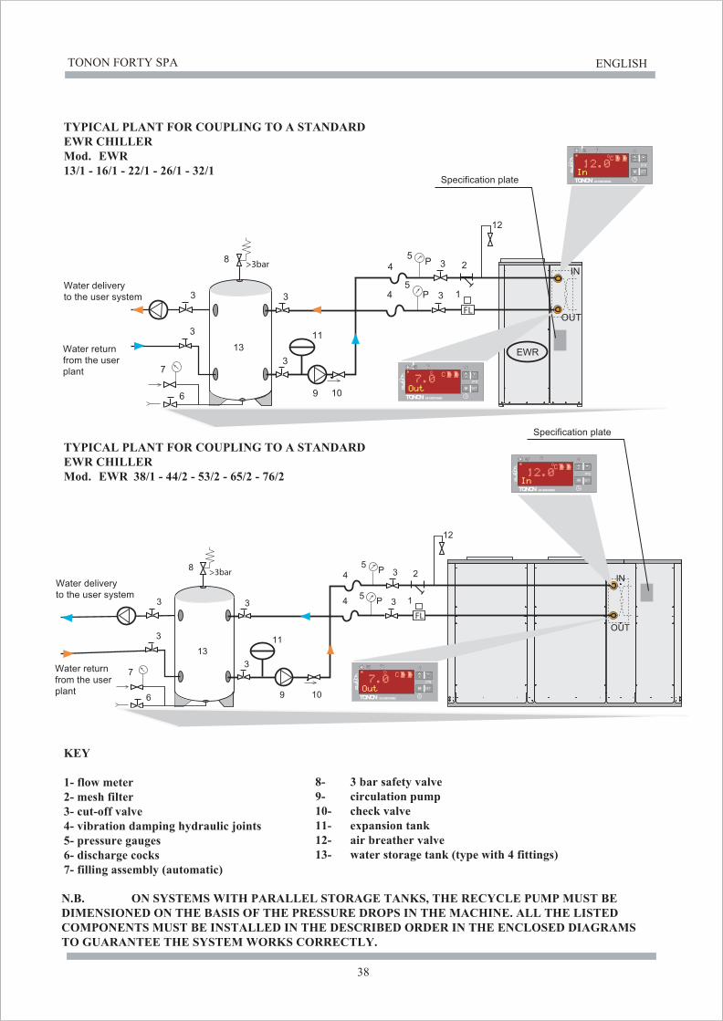
TONON FORTY SPA ENGLISH
38
P
P>3bar
1
2
3
3
3
3 4
4
5
5
6
7
8
9 10
11
12
13
3
3
P
P>3bar
1
2
3
3
3
3 4
4
5
5
6
7
8
9 10
11
12
13
3
3
EWR
IN
OUT
OUT
IN
FL
FL
TYPICAL PLANT FOR COUPLING TO A STANDARD
EWR CHILLER
Mod. EWR
13/1 - 16/1 - 22/1 - 26/1 - 32/1
TYPICAL PLANT FOR COUPLING TO A STANDARD
EWR CHILLER
Mod. EWR 38/1 - 44/2 - 53/2 - 65/2 - 76/2
KEY
1- flow meter
2- mesh filter
3- cut-off valve
4- vibration damping hydraulic joints
5- pressure gauges
6- discharge cocks
7- filling assembly (automatic)
8- 3 bar safety valve
9- circulation pump
10- check valve
11- expansion tank
12- air breather valve
13- water storage tank (type with 4 fittings)
N.B. ON SYSTEMS WITH PARALLEL STORAGE TANKS, THE RECYCLE PUMP MUST BE
DIMENSIONED ON THE BASIS OF THE PRESSURE DROPS IN THE MACHINE. ALL THE LISTED
COMPONENTS MUST BE INSTALLED IN THE DESCRIBED ORDER IN THE ENCLOSED DIAGRAMS
TO GUARANTEE THE SYSTEM WORKS CORRECTLY.
Water delivery
to the user system
Water return
from the user
plant
Water delivery
to the user system
Water return
from the user
plant
Specification plate
M SET
prg
m.a.Ch.
��
1 2
������
M SET
prg
m.a.Ch.
��
1 2
����
M SET
prg
m.a.Ch.
��
1 2
������
M SET
prg
m.a.Ch.
��
1 2
����
Specification plate

TONON FORTY SPA ENGLISH
39
Mod. EPR
13/1 - 16/1 - 22/1 - 26/1 - 32/1
Mod. EPR 38/1 - 44/2 - 53/2 - 65/2 - 76/2
IN
IN
OUTP
P
>3bar
2
3
33
4
4
5
5
6
7
8
12
13
3
9 10
11
1
3
FL
P
P
>3bar 1
2
3
333
4
4
5
5
6
7
8
9 10
11
12
13
3
FL
TYPICAL PLANT FOR COUPLING TO A STANDARD
EPR HEAT PUMP UNIT
TYPICAL PLANT FOR COUPLING TO A STANDARD
EPR HEAT PUMP UNIT
KEY
1- flow meter
2- mesh filter
3- cut-off valve
4- vibration damping hydraulic joints
5- pressure gauges
6- discharge cocks
7- filling assembly (automatic)
8- 3 bar safety valve
9- circulation pump
10- check valve
11- expansion tank
12- air breather valve
13- water storage tank (type with 2 fittings)
N.B. ON UNITS WITH STORAGE TANKS FITTED STANDARD, THE CIRCULATION PUMP MUST BE
DIMENSIONED TO OVERCOME ANY PRESSURE DROPS IN THE MACHINE AND THE PLANT.
ALL THE LISTED COMPONENTS MUST BE INSTALLED IN THE DESCRIBED ORDER IN THE
ENCLOSED DIAGRAMS TO GUARANTEE THE SYSTEM WORKS CORRECTLY
Specification plate
Specification plate
M SET
prgm.a.Ch.
��
1 2
������
M SET
prg
m.a.Ch.
��
1 2
����
Water delivery
to the user system
Water return
from the userplant
Water delivery
to the user systemWater return
from the user
plant
OUT
M SET
prg
m.a.Ch.
��
1 2
������
M SET
prgm.a.Ch.
��
1 2
����

TONON FORTY SPA ENGLISH
40
IN
M SET
prg
m.a.Ch.
������
1 2
��
M SET
prg
m.a.Ch.
����
1 2
��
IN
OUTP
P
>3bar 1
2
3
3
3
3
4
4
5
5
6
7
8
9 10
11
12
13
3
3
FL
P
P
>3bar 1
2
3
3
3
3
4
4
5
5
6
7
8
9 10
11
12
13
3
3
FL
TYPICAL PLANT FOR COUPLING TO A STANDARD
EPR HEAT PUMP UNIT
TYPICAL PLANT FOR COUPLING TO A STANDARD
EPR HEAT PUMP UNIT
KEY
1- flow meter
2- mesh filter
3- cut-off valve
4- vibration damping hydraulic joints
5- pressure gauges
6- discharge cocks
7- filling assembly (automatic)
8- 3 bar safety valve
9- circulation pump
10- check valve
11- expansion tank
12- air breather valve
13- water storage tank (type with 4 fittings)
N.B. ON SYSTEMS WITH PARALLEL STORAGE TANKS, THE RECYCLE PUMP MUST BE
DIMENSIONED ON THE BASIS OF THE PRESSURE DROPS IN THE MACHINE. ALL THE LISTED
COMPONENTS MUST BE INSTALLED IN THE DESCRIBED ORDER IN THE ENCLOSED DIAGRAMS
TO GUARANTEE THE SYSTEM WORKS CORRECTLY.
Mod. EPR
13/1 - 16/1 - 22/1 - 26/1 - 32/1
Mod. EPR 38/1 - 44/2 - 53/2 - 65/2 - 76/2
Water delivery
from the user
Water delivery
to the user system
Water return
from the user
plant
Specification plate
to the user system
plant
Water return
OUT
M SET
prg
m.a.Ch.
������
1 2
��
M SET
prg
m.a.Ch.
����
1 2
��

TONON FORTY SPA ENGLISH
42
M SET
prgm.a.Ch.
���� ������
1 2
��
M SET
prg
m.a.Ch.
������
1 2
��
>3bar8
10
FL
EPR
OUTKAP
IN
1
2
3
4
5
6
7
9
9
P
P
11
5
12
512
13
IN
OUT
M SET
prg
m.a.Ch.
M SET
prg
m.a.Ch.
���� ������
1 2
��
������
1 2
��
>3barFLKAP
6
7
8
10
3
4
5
1
2
9
9
P
P
5
12
512
13
11
Mod. EPR + KAP
13/1 - 16/1 - 22/1 - 26/1 - 32/1
Mod. EPR + KAP 38/1 - 44/2 - 53/2 - 65/2 - 76/2
TYPICAL PLANT FOR COUPLING TO A STANDARD
EWR HEAT PUMP UNIT
TYPICAL PLANT FOR COUPLING TO A STANDARD
EWR HEAT PUMP UNIT
KEY
1- flow meter
2- expansion tank
3- check valve
4- circulation pump
5- cut-off valve
6- discharge cocks
7- filling assembly (automatic)
8- 3 bar safety valve
9-
10-
11-
12- pressure gauges
air breather valve
13- mesh filter
N.B. ON UNITS WITH STORAGE TANKS FITTED STANDARD, THE CIRCULATION PUMP MUST BE
DIMENSIONED TO OVERCOME ANY PRESSURE DROPS IN THE MACHINE AND THE PLANT.
ALL THE LISTED COMPONENTS MUST BE INSTALLED IN THE DESCRIBED ORDER IN THE
ENCLOSED DIAGRAMS TO GUARANTEE THE SYSTEM WORKS CORRECTLY
vibration damping hydraulic jointswater storage tank
Water delivery
to the user system
Water return
from the user
plant
Water delivery
to the user systemWater return
from the user
plant
Specification plate
Specification plate

TONON FORTY SPA ENGLISH
41
Mod. EWR + KAP
13/1 - 16/1 - 22/1 - 26/1 - 32/1
Mod. EWR + KAP 38/1 - 44/2 - 53/2 - 65/2 - 76/2
M SET
prg
m.a.Ch.
��� ��� �����
1 2
���
M SET
prg
m.a.Ch.
��������
1 2
��
>3bar8
10
FL
EWR
INKAP
OUT
IN
M SET
prg
m.a.Ch.
M SET
prg
m.a.Ch.
��� ��� �����
1 2
���
��������
1 2
��
>3barFLKAP
OUT
1
2
3
4
5
6
7
9
9
6
7
8
10
3
4
5
1
2
9
9
P
P
11
5
12
512
13
P
P
5
12
512
13
11
TYPICAL PLANT FOR COUPLING TO A STANDARD
EWR CHILLER
TYPICAL PLANT FOR COUPLING TO A STANDARD
EWR CHILLER
KEY
1- flow meter
2- expansion tank
3- check valve
4- circulation pump
5- cut-off valve
6- discharge cocks
7- filling assembly (automatic)
8- 3 bar safety valve
9-
10-
11-
12- pressure gauges
air breather valve
13- mesh filter
N.B. ON UNITS WITH STORAGE TANKS FITTED STANDARD, THE CIRCULATION PUMP MUST BE
DIMENSIONED TO OVERCOME ANY PRESSURE DROPS IN THE MACHINE AND THE PLANT.
ALL THE LISTED COMPONENTS MUST BE INSTALLED IN THE DESCRIBED ORDER IN THE
ENCLOSED DIAGRAMS TO GUARANTEE THE SYSTEM WORKS CORRECTLY
Water delivery
to the user system
Water return
from the user
plant
Water delivery
to the user systemWater return
from the user
plant
Specification plate
Specification plate
vibration damping hydraulic jointswater storage tank
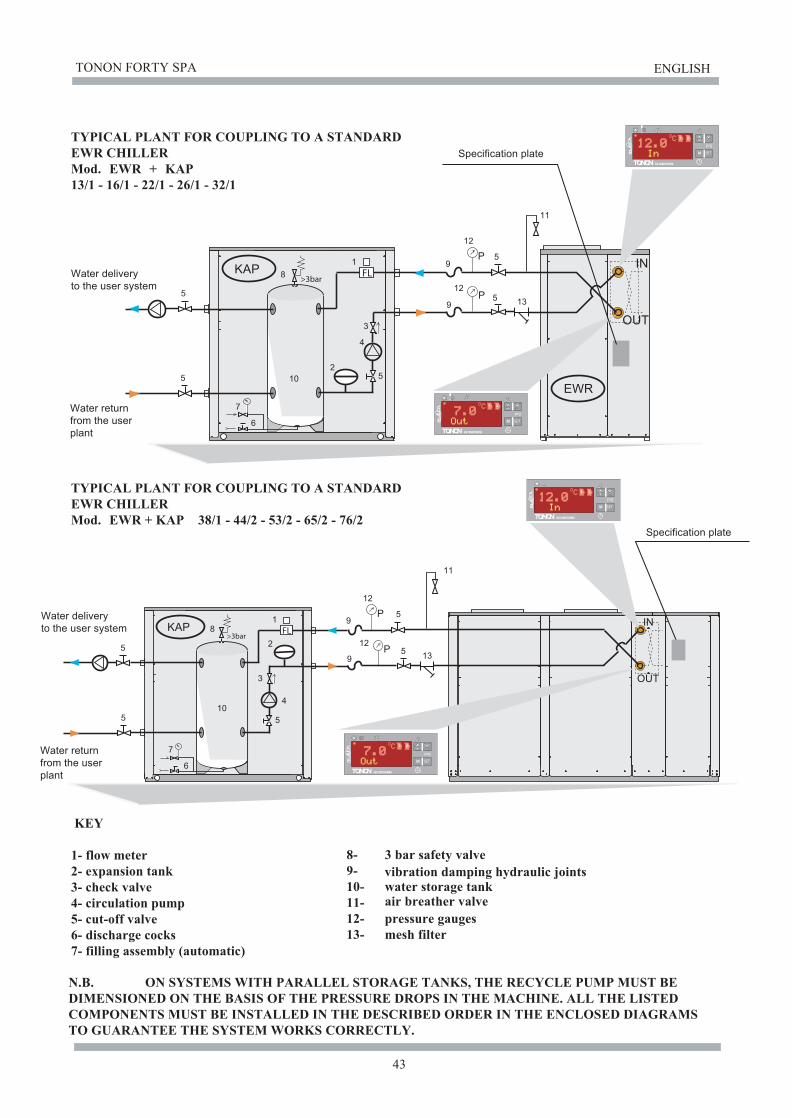
TONON FORTY SPA ENGLISH
43
Mod. EWR + KAP
13/1 - 16/1 - 22/1 - 26/1 - 32/1
Mod. EWR + KAP 38/1 - 44/2 - 53/2 - 65/2 - 76/2
M SET
prg
m.a.Ch.
��� �����
1 2
���
M SET
prg
m.a.Ch.
������
1 2
��
>3bar8
10
FL
EWR
INKAP
OUT
1
2
3
4
5
6
7
9
9
P
P
11
5
12
512
135
5
OUT
IN
M SET
prg
m.a.Ch.
M SET
prg
m.a.Ch.
��� �����
1 2
���
������
1 2
��
>3barFLKAP
6
7
8
10
3
4
5
1
2
9
9
P
P
5
12
512
13
11
5
5
N.B. ON SYSTEMS WITH PARALLEL STORAGE TANKS, THE RECYCLE PUMP MUST BE
DIMENSIONED ON THE BASIS OF THE PRESSURE DROPS IN THE MACHINE. ALL THE LISTED
COMPONENTS MUST BE INSTALLED IN THE DESCRIBED ORDER IN THE ENCLOSED DIAGRAMS
TO GUARANTEE THE SYSTEM WORKS CORRECTLY.
KEY
1- flow meter
2- expansion tank
3- check valve
4- circulation pump
5- cut-off valve
6- discharge cocks
7- filling assembly (automatic)
8- 3 bar safety valve
9-
10-
11-
12- pressure gauges
air breather valve
13- mesh filter
vibration damping hydraulic jointswater storage tank
TYPICAL PLANT FOR COUPLING TO A STANDARD
EWR CHILLER
TYPICAL PLANT FOR COUPLING TO A STANDARD
EWR CHILLER
Water delivery
to the user system
Water return
from the user
plant
Water delivery
to the user system
Water return
from the user
plant
Specification plate
Specification plate

TONON FORTY SPA ENGLISH
44
Mod. EPR + KAP
13/1 - 16/1 - 22/1 - 26/1 - 32/1
Mod. EPR + KAP 38/1 - 44/2 - 53/2 - 65/2 - 76/2
>3bar8
10
FLKAP1
2
3
4
5
6
7
5
5
>3barFLKAP
6
7
8
10
3
4
5
1
2
5
5
M SET
prgm.a.Ch.
������
1 2
��
M SET
prg
m.a.Ch.
����
1 2
��
EPR
OUT
IN
9
9
P
P
11
5
12
512
13
IN
OUT
M SET
prg
m.a.Ch.
M SET
prg
m.a.Ch.
������
1 2
��
������
1 2
��
9
9
P
P
5
12
512
13
11
N.B. ON SYSTEMS WITH PARALLEL STORAGE TANKS, THE RECYCLE PUMP MUST BE
DIMENSIONED ON THE BASIS OF THE PRESSURE DROPS IN THE MACHINE. ALL THE LISTED
COMPONENTS MUST BE INSTALLED IN THE DESCRIBED ORDER IN THE ENCLOSED DIAGRAMS
TO GUARANTEE THE SYSTEM WORKS CORRECTLY.
KEY
1- flow meter
2- expansion tank
3- check valve
4- circulation pump
5- cut-off valve
6- discharge cocks
7- filling assembly (automatic)
8- 3 bar safety valve
9-
10-
11-
12- pressure gauges
air breather valve
13- mesh filter
vibration damping hydraulic jointswater storage tank
TYPICAL PLANT FOR COUPLING TO A STANDARD
EPR HEAT PUMP UNIT
TYPICAL PLANT FOR COUPLING TO A STANDARD
EPR HEAT PUMP UNIT
Specification plate
Specification plate
Water delivery
to the user system
Water return
from the user
plant
Water delivery
to the user system
Water return
from the user
plant

ma
nu
al
Ew
r-E
pr
da
te 2
5/0
9/2
00
6 c
od
e -
67
37
00
01
3 G
B