Embed Size (px)
Citation preview

Global Technical Operations gto.gnresound.com
Lautrupbjerg 9 • DK-2750 Ballerup • Denmark E-Mail: [email protected]
Technical Manual Beltone MARQ

Doc 0125910 rev. I
Page 2 of 22
Not subject to issue control when printed
Table of Contents
Description...........................................................................................................................3Matrix & product information................................................................................................4Part lists ........................................................................................................................... 5-8Power dome tool..................................................................................................................9 Exploded view ...................................................................................................................10Wiring diagram ..................................................................................................................11 Mic cover removal .............................................................................................................12Battery / Battery door removal ...........................................................................................13Housing removal................................................................................................................14Adding new colour / replacing housing ..............................................................................15Microphone replacement ...................................................................................................16Testing equipment .............................................................................................................17Testing protocol for HPG & MPG devices..........................................................................18Testing the device with test fixture .....................................................................................19Testing HPG receiver tube only ........................................................................................20 Testing MPG receiver tube only ........................................................................................21Receiver tube replacement on test fixture .........................................................................22

Doc 0125910 rev. I
Page 3 of 22
Not subject to issue control when printed
Description
The Marq17 & Marq9 is an occlusion free Mini BTE RIE product which incorporate a new receiver dome system with an in-moulded wax filter. Other characteristics are:• Smallest RIE product ever introduced• Significant increased available gain expected vs. competitors and other open fittings for Beltone • Available in these Models under the EDGE|collection tab: • Marq17 Open • Marq17 Standard • Marq17 HP Open • Marq17 HP Standard • Marq9 Open • Marq9 Standard • Marq9 HP Open • Marq9 HP standard• Dual microphone • Two Power Levels - Normal Power and High Power• Compatible with Solus 2.2 or higher• 10A size battery• 106/107 hrs of real time usage• Coyote 3.1 hybrid • No control options (VC, PB, TC)• Compatible with existing flex programming system CS63 cable with a fresh 10A battery for programming• Field replaceable sports lock.• New RIE domes with integrated wax protection + additional wax protection in receiver housing.• Comes in 12 colors: Charcoal, Brown, Grey, Light Grey, Beige, Stone, Arctic Ice, Transparent, Dark Metallic, Blue, Purple and Black.
The Marq17 & Marq9 design takes advantage of the current popularity of a small housing due to the RIE. The housing will come in optional colors and be changeable and reusable at the dispenser’s office.
Doc 0125910 rev. I
Page 4 of 22
Not subject to issue control when printed
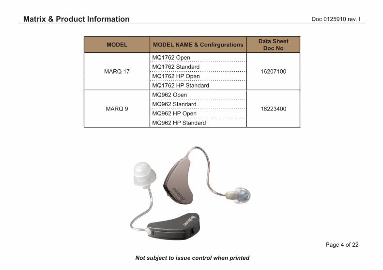
Matrix & Product Information
MODEL MODEL NAME & Confirgurations Data Sheet Doc No
MARQ 17
MQ1762 Open
16207100MQ1762 StandardMQ1762 HP OpenMQ1762 HP Standard
MARQ 9
MQ962 Open
16223400MQ962 StandardMQ962 HP OpenMQ962 HP Standard

Doc 0125910 rev. I
Page 5 of 22
Not subject to issue control when printed
Description Part No
C3.1 Coyote HybridBottom Housing with Laser mark (MQ17)Bottom Housing with Laser mark (MQ9)O-ringMic (Front and back) TM-60020-C36Mic Gasket (Front)Mic Gasket (Rear)Mic FrameProgramming contactsHinge PinBattery contact positive (+)Battery contact negative (-)WIRE, ESW, AMBER 7x32µ 14MMWIRE, ESW, GREEN 7x32µ 14MMWIRE, ESW, BLUE 7x32µ 14MMWIRE, ESW, RED 7x32µ 8MMWIRE, ESW, GREEN 7x32µ 8MMWIRE, ESW, RED 7x32µ 6MMWIRE, ESW, AMBER 7x32µ 6MMWIRE, ESW, GREEN 7x32µ 6MMWIRE, ESW, RED 7x32µ 7MMWIRE, ESW, AMBER 7x32µ 7MMWIRE, ESW, GREEN 7x32µ 7MM
1701490016015900 160159501607380015988600 159884001598841015987200159874001598810015988300159883101512971415129814151299141512960815129808151296061512970615129806151296071512970715129807
Please find p/n’s and pics of the parts used for test on the last pages
* For coat SL1367, check e.g. vendor website: www.peters.de to **purchase locally
Description Part No
PIN BAG, MARQREMOVAL TOOLInsulating pad (for hybrid)CONFORMAL COATING,SL1367
Receiver Tube: MPG (Medium Power Gain)TUBE ASM, REC,TEST, STRAIGHT(modified)
COUPLER INSERT,DSA (brass)BATTERY PILL, 10ATEST FIXTUREPR.CABLE CS63STRIP CS63 (10PK)
161035001635230013006-002
*
15990700
1616930017449200161694005093170250931703
Removal Tool
Part List

Doc 0125910 rev. I
Page 6 of 22
Not subject to issue control when printed
Part List - Receiver & Domes
Rec Tube Size NP HP
0L 18581300 18582300
0R 18581400 18582400
1L 18581500 18582500
1R 18581600 18582600
2L 18581700 18582700
2R 18581800 18582800
3L 18581900 18582900
3R 18582000 18583000
4L 18582100 18583100
4R 18582200 18583200
Rec Tube blister pack containing one rec tube
DOME ST Tulip
DOMESizes L,M,S
DOMES USED WITH NP REC
Description Bag (10 pcs)
Blister Pack (8 pcs)
DOME,REC,SZ5,SM 18501200 18607800
DOME,REC,SZ7,MDM 18501300 18607900
DOME,REC,SZ10,LGE 18501400 18608000
DOME,REC,TULIP,STD 18501800 18608400
DOME,REC,PWR,SM 18501900 18608500
DOME,REC,PWR,MDM 18502000 18608600
DOME,REC,PWR,LGE 18502100 18608700
DOMES USED WITH HP REC
Description Bag (10 pcs)
Blister Pack (8 pcs)
DOME,REC,PWR,SM 18501900 18608500
DOME,REC,PWR,MDM 18502000 18608600
DOME,REC,PWR,LGE 18502100 18608700
Power DomesSizes L,M,S
Doc 0125910 rev. I
Page 7 of 22
Not subject to issue control when printed
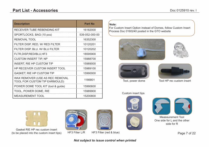
Note: For Custom Insert Option instead of Domes, follow Custom Insert Process Doc 0160240 posted in the GTO website
Description Part No
RECEIVER TUBE REBENDING KIT 16182000
SPORTLOCKS, BAG (10 pcs) 539-052-000-00
REMOVAL TOOL 16352300
FILTER DISP, RED, W/ RED FILTER 10120201
FILTER DISP, BLU, W/ BLU FILTER 10120202
FLTR,DISP,RED/BLU,HF3 18595900
CUSTOM INSERT TIP, NP 15988700
INSERT, RIE HP CUSTOM TIP 15989000
HP RECEIVER CUSTOM INSERT TOOL 15989100
GASKET, RIE HP CUSTOM TIP 15990000
WAX REMOVER (USE AS REC REMOVAL TOOL FOR CUSTOM TIP EARMOULD) 1186801
POWER DOME TOOL KIT (tool & guide) 15990600
TOOL, POWER DOME, RIE 15989900
MEASUREMENT TOOL 15200800
Meassurement ToolOne side for L and the other
side for R
Tool, power dome Tool HP rec custom insert
Custom insert tips
NP
HF3 Filter L/RGasket RIE HP rec custom insert
(to be placed into the custom insert tips) HF3 Filter (red & blue)
HP
Part List - Accessories

Doc 0125910 rev. I
Page 8 of 22
Not subject to issue control when printed
COLOUR HSG TOP MIC COVER BATT DOOR
GREY 16015800 15987300 16181100
STONE 16015801 15987301 16181101
CHARCOAL 16015802 15987302 16181102
BROWN 16015803 15987303 16181103
LIGHT GREY 16015804 15987304 16181104
BEIGE 16015805 15987305 16181105
ARCTIC ICE 16015806 15987306 16181106
DARK METAL 16015807 15987307 16181107
TRANSP 16015808 15987308 16181108
PURPLE 16015809 15987309 16181109
BLUE 16015810 15987310 16181110
BLACK 16015811 15987311 16181111
Part List - Housing Parts & Replacement Packs
Part Description Part No
REPLACEMENT PK,BELTONE 62,GREY 16112100N*
REPLACEMNT PK,BELTONE 62,STONE 16112200N*
REPLACEMNT PK,BELTONE 62,CHARC 16112300N*
REPLACEMNT PK,BELTONE 62,BROWN 16112400N*
REPLACMNT PK,BELTONE 62,LT GRY 16112500N*
REPLACEMNT PK,BELTONE 62,BEIGE 16112600N*
RPLCMNT PK,BELTONE 62,ARCT ICE 16112700
RPLCMNT PK,BELTONE 62,DRK MTLC 16112800
REPLACMNT PK,BELTONE 62,TRANSP 16112900
REPLACMNT PK,BELTONE 62,PURPLE 16113000
REPLACEMENT PK,BELTONE 62,BLUE 16113100
REPLACEMNT PK,BELTONE 62,BLACK 16113200
* These replacement packs are nano coated

Doc 0125910 rev. I
Page 9 of 22
Not subject to issue control when printed
Power Dome Tool
As the HPG receiver is pushed into the Power Dome, carefull pull out the Power Dome Tool
Place the longer length of the rectangular cavity of the power dome over the Power Dome Tool.
Ensure that the Power dome is installed on the Power Dome Tool by checking it and it is flushed even with the tool as shown (3rd pic)
Squeeze and hold bottom of the Power Dome Tool to open the Power Dome rectangular cavity.Insert the HPG Receiver, with the longer length of the receiver parallel to the longer length of the rectangular cavity of the Power Dome
Prepare a HF3 tool with HF3
Insert HF3 tool with HF3 all the way in the power dome until it passes through the rectangular cavity of the power dome
Power Dome Tool

Doc 0125910 rev. I
Page 10 of 22
Not subject to issue control when printed
Battery door
Battery
Mic Gasket
Microphone
Programming contacts
Mic Frame
Hinge pin
Battery Contacts
Bottom housing
Hybrid C3.1
Receiver Tube
Top Housing
Mic Cover
Sport lock
O ring
Exploded View
Doc 0125910 rev. I
Page 11 of 22
Not subject to issue control when printed
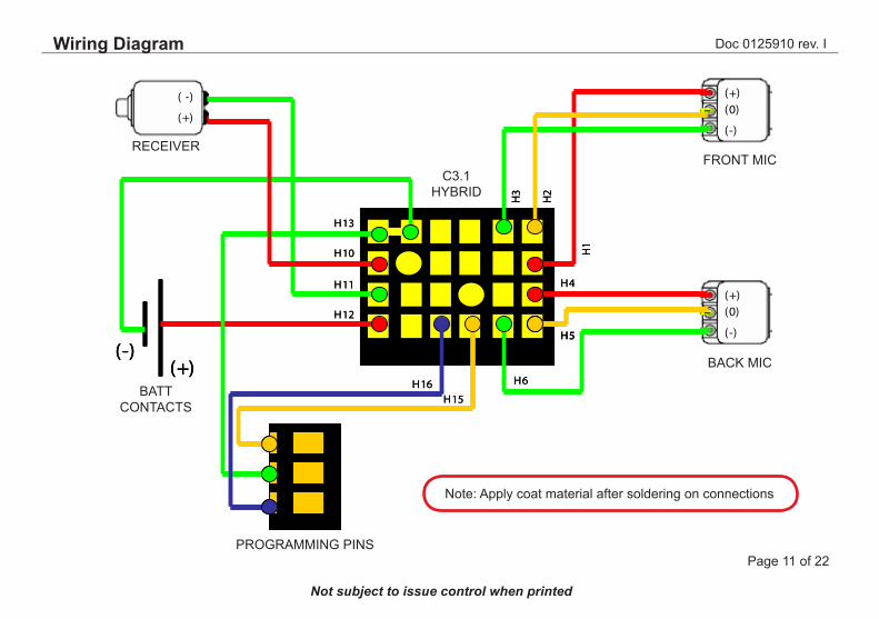
(-)(+)
B A T T CONT A CT S
(+)(0)
(-)
(+)(0)
(-)
(+)
( -)
FR ONT MIC
B A CK MIC
R E CE IV E R
C3.1 HY B R ID
H5
H1
H4H11
H13
H3
H6
H2
H10
H12
H15H16
PR OGR A MMING PINS
(-)(+)
B A T T CONT A CT S
(-)(+)
B A T T CONT A CT S
(+)(0)
(-)
(+)(0)
(-)
(+)(0)
(-)
(+)(0)
(-)
(+)
( -)
(+)
( -)
FR ONT MIC
B A CK MIC
R E CE IV E R
C3.1 HY B R ID
H5H5
H1
H4H11
H13
H3
H6
H2
H10
H12
H15H16
PR OGR A MMING PINS
Note: Apply coat material after soldering on connections
RECEIVERFRONT MIC
BACK MIC
BATT CONTACTS
C3.1HYBRID
PROGRAMMING PINS
Wiring Diagram

Doc 0125910 rev. I
Page 12 of 22
Not subject to issue control when printed
Align the blade part of the removal tool onto the slot between mic cover and the top housing
Insert the blade part of the removal tool onto the slot between mic cover and the top housing
Supporting the other end of the mic cover while lifting the other end with the removal tool pressed downwards to release the mic cover from the top housing
Support
Removal Toolp/n 16352300
Mic Cover Removal
Doc 0125910 rev. I
Page 13 of 22
Not subject to issue control when printed
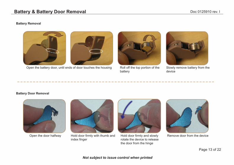
Open the door halfway Hold door firmly with thumb and index finger
Hold door firmly and slowly rotate the device to release the door from the hinge
Remove door from the device
Open the battery door, until ends of door touches the housing Roll off the top portion of the battery
Slowly remove battery from the device
Battery Removal
Battery Door Removal
Battery & Battery Door Removal
Doc 0125910 rev. I
Page 14 of 22
Not subject to issue control when printed
Size 13 and 312 Size 10
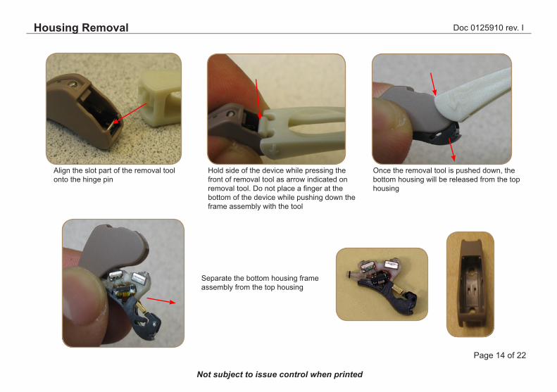
Align the slot part of the removal tool onto the hinge pin
Once the removal tool is pushed down, the bottom housing will be released from the top housing
Separate the bottom housing frame assembly from the top housing
Hold side of the device while pressing the front of removal tool as arrow indicated on removal tool. Do not place a finger at the bottom of the device while pushing down the frame assembly with the tool
Housing Removal

Doc 0125910 rev. I
Page 15 of 22
Not subject to issue control when printed
Bottom housing frame assembly
Get new desired colour or replacement housing, door, mic cover & receiver tube and add it on the bottom housing frame assembly
Add batt door, receiver tube and mic cover to complete unit
Mic cover
Receiver Tube
Insert bottom housing assembly horizontally into housing. Ensure the nose part of the assembly is centered when inserting bottom assembly
Push round end of bottom housing assembly into hous-ing until it clicks
Batt door
Adding New Colour/ Replacing Housing
Doc 0125910 rev. I
Page 16 of 22
Not subject to issue control when printed
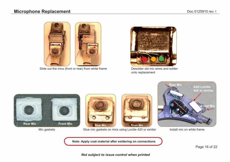
Slide out the mics (front or rear) from white frame Desolder old mic wires and solder onto replacement
Install mic on white frameGlue mic gaskets on mics using Loctite 420 or similarMic gaskets
Front MicRear Mic
Front Mic
Rear Mic
Front MicRear Mic
Add Loctite 420 or similar
Note: Apply coat material after soldering on connections
Microphone Replacement

Doc 0125910 rev. I
Page 17 of 22
Not subject to issue control when printed
Coupler Insert to be used for final HI test
p/n 16169300
Connect the flex to the prog cable by using the flex end marked with an arrow
Prog cable CS63 p/n 50931702Flex strip for CS63 p/n 50931703 (10 pcs pack)
Flex strip
Prog cable CS63 (3 pin)
Flex strip
Rec Tubeconnector
Test Rec Tube NPp/n 15990700
Test Fixture p/n 16169400
Note : Fixture does not come with test rec tube. It has to be ordered. Rec tube can be replaced as needed
Either of the shown 2cc coupler inserts must be used for rec test. Both inserts can be ordered with GTO Dept in HQ. More info to be found on GTO website under “DSA6000 Documentation”
2cc couplerp/n 30-4838800
to be ordered with GTO Dept/HQ Ballerup DK
Test Equipment
Batt pill 10A must be used during testp/n 17449200
Doc 0125910 rev. I
Page 18 of 22
Not subject to issue control when printed
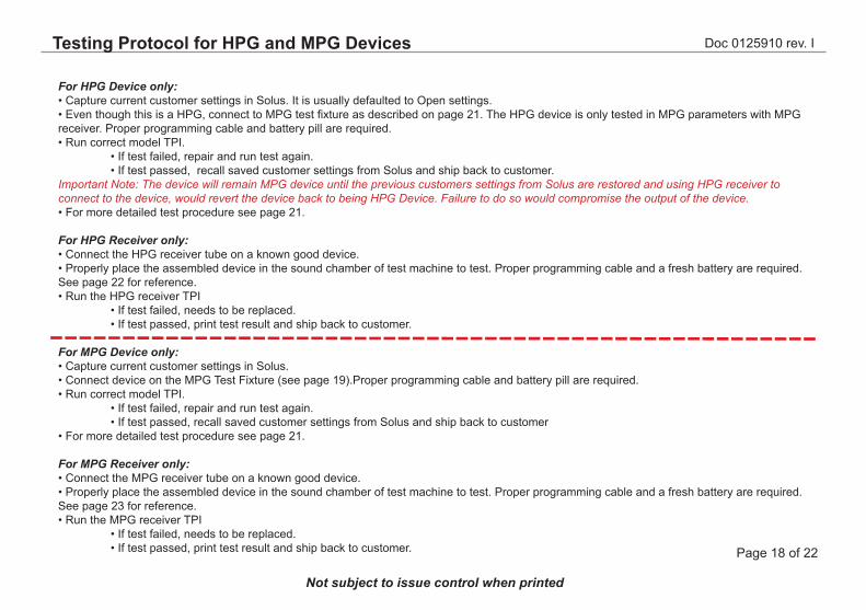
For HPG Device only:• Capture current customer settings in Solus. It is usually defaulted to Open settings.• Even though this is a HPG, connect to MPG test fixture as described on page 21. The HPG device is only tested in MPG parameters with MPG receiver. Proper programming cable and battery pill are required.• Run correct model TPI. • If test failed, repair and run test again. • If test passed, recall saved customer settings from Solus and ship back to customer.Important Note: The device will remain MPG device until the previous customers settings from Solus are restored and using HPG receiver to connect to the device, would revert the device back to being HPG Device. Failure to do so would compromise the output of the device.• For more detailed test procedure see page 21.
For HPG Receiver only:• Connect the HPG receiver tube on a known good device.• Properly place the assembled device in the sound chamber of test machine to test. Proper programming cable and a fresh battery are required. See page 22 for reference.• Run the HPG receiver TPI • If test failed, needs to be replaced. • If test passed, print test result and ship back to customer.
For MPG Device only:• Capture current customer settings in Solus. • Connect device on the MPG Test Fixture (see page 19).Proper programming cable and battery pill are required.• Run correct model TPI. • If test failed, repair and run test again. • If test passed, recall saved customer settings from Solus and ship back to customer• For more detailed test procedure see page 21.
For MPG Receiver only:• Connect the MPG receiver tube on a known good device.• Properly place the assembled device in the sound chamber of test machine to test. Proper programming cable and a fresh battery are required. See page 23 for reference.• Run the MPG receiver TPI • If test failed, needs to be replaced. • If test passed, print test result and ship back to customer.
Testing Protocol for HPG and MPG Devices
Doc 0125910 rev. I
Page 19 of 22
Not subject to issue control when printed
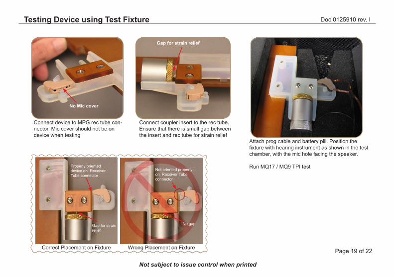
Attach prog cable and battery pill. Position the fixture with hearing instrument as shown in the test chamber, with the mic hole facing the speaker.
Run MQ17 / MQ9 TPI test
Connect device to MPG rec tube con-nector. Mic cover should not be on device when testing
Connect coupler insert to the rec tube. Ensure that there is small gap between the insert and rec tube for strain relief
Gap for strain relief
No Mic cover
Correct Placement on Fixture
Gap for strain relief
Properly oriented device on Receiver Tube connector
Not oriented properly on Receiver Tube connector
No gap
Testing Device using Test Fixture
Wrong Placement on Fixture
Doc 0125910 rev. I
Page 20 of 22
Not subject to issue control when printed
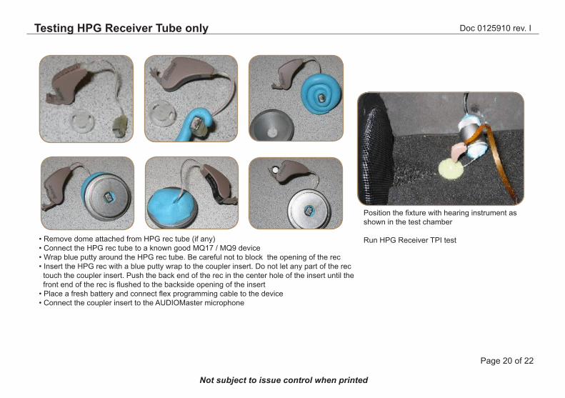
Position the fixture with hearing instrument as shown in the test chamber
Run HPG Receiver TPI test• Remove dome attached from HPG rec tube (if any)• Connect the HPG rec tube to a known good MQ17 / MQ9 device• Wrap blue putty around the HPG rec tube. Be careful not to block the opening of the rec• Insert the HPG rec with a blue putty wrap to the coupler insert. Do not let any part of the rec ..touch the coupler insert. Push the back end of the rec in the center hole of the insert until the ..front end of the rec is flushed to the backside opening of the insert• Place a fresh battery and connect flex programming cable to the device• Connect the coupler insert to the AUDIOMaster microphone
Testing HPG Receiver Tube only
Doc 0125910 rev. I
Page 21 of 22
Not subject to issue control when printed
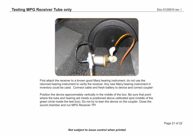
First attach the receiver to a known good Marq hearing instrument, do not use the returned hearing instrument to verify the receiver. Any new Marq hearing instrument in inventory could be used. Connect cable and fresh battery to device and correct coupler
Position the device approximately vertically in the middle of the box. Be sure that point where the tube and hearing aid meets is positioned above calibrated spot (middle of the green circle inside the test box). Do not try to lean the device on the coupler. Close the sound chamber and run MPG Receiver TPI
Testing MPG Receiver Tube only
Doc 0125910 rev. I
Page 22 of 22
Not subject to issue control when printed
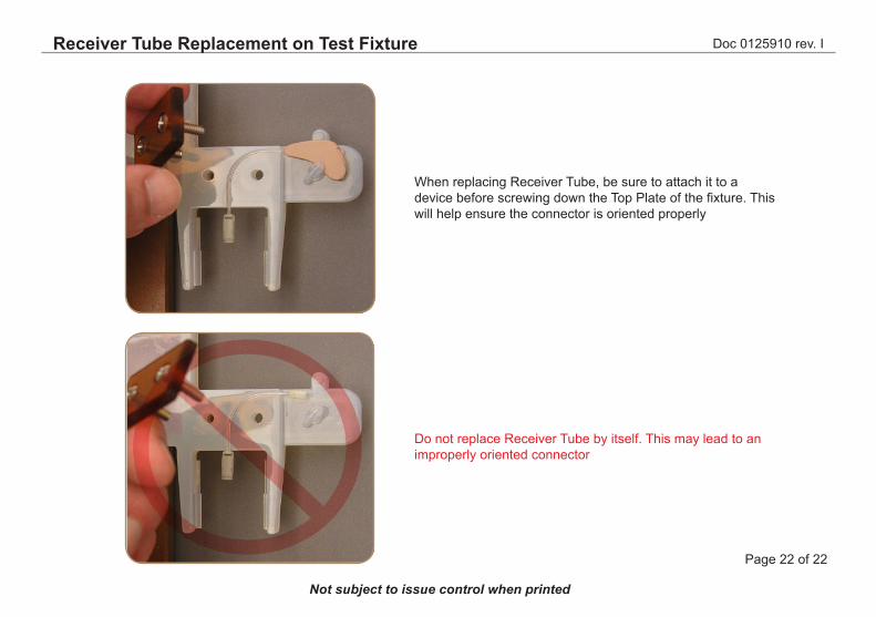
When replacing Receiver Tube, be sure to attach it to a device before screwing down the Top Plate of the fixture. This will help ensure the connector is oriented properly
Do not replace Receiver Tube by itself. This may lead to an improperly oriented connector
Receiver Tube Replacement on Test Fixture