Embed Size (px)
Citation preview

1
TECHNICAL INSTRUCTIONS
FOR
SAFETY RECALL J02
VALVE SPRING REPLACMENT
CERTAIN 2013 MY FR-S
UPDATED 12/20/2018 Update 12/20/18
- (Pg. 20) Checksheet added to confirm repair quality
The repair quality of covered vehicles is extremely important to Toyota. All dealership technicians performing
this recall are required to successfully complete the most current version of the E-Learning course “Safety
Recall and Service Campaign Essentials”. To ensure that all vehicles have the repair performed correctly;
technicians performing this recall repair are required to currently hold at least one of the following certification
levels:
• Expert Technician (Engine) • Master Technician • Master Diagnostic Technician It is the dealership’s responsibility to select technicians with the above certification level or greater to perform this recall repair. Carefully review your resources, the technician skill level, and ability before assigning technicians to this repair. It is important to consider technician days off and vacation schedules to ensure there are properly trained technicians available to perform this repair at all times.
2
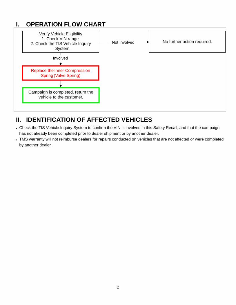
Verify Vehicle Eligibility 1. Check VIN range.
2. Check the TIS Vehicle Inquiry System.
No further action required.
I. OPERATION FLOW CHART
II. IDENTIFICATION OF AFFECTED VEHICLES
• Check the TIS Vehicle Inquiry System to confirm the VIN is involved in this Safety Recall, and that the campaign has not already been completed prior to dealer shipment or by another dealer.
• TMS warranty will not reimburse dealers for repairs conducted on vehicles that are not affected or were completed by another dealer.
Involved
Not Involved
Campaign is completed, return the vehicle to the customer.
Replace the Inner Compression Spring (Valve Spring)
3
III. PREPARATION
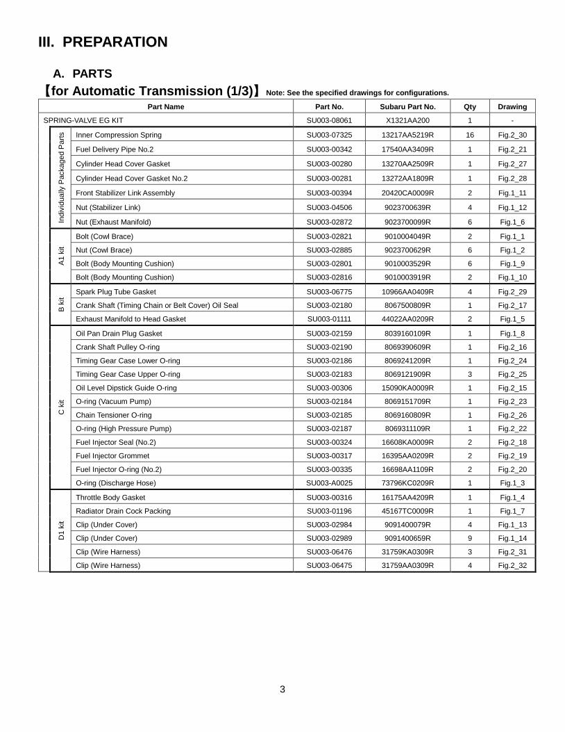
A. PARTS 【for Automatic Transmission (1/3)】Note: See the specified drawings for configurations.
Part Name Part No. Subaru Part No. Qty Drawing
SPRING-VALVE EG KIT SU003-08061 X1321AA200 1 -
Indi
vidu
ally
Pac
kage
d Pa
rts
Inner Compression Spring SU003-07325 13217AA5219R 16 Fig.2_30
Fuel Delivery Pipe No.2 SU003-00342 17540AA3409R 1 Fig.2_21
Cylinder Head Cover Gasket SU003-00280 13270AA2509R 1 Fig.2_27
Cylinder Head Cover Gasket No.2 SU003-00281 13272AA1809R 1 Fig.2_28
Front Stabilizer Link Assembly SU003-00394 20420CA0009R 2 Fig.1_11
Nut (Stabilizer Link) SU003-04506 9023700639R 4 Fig.1_12
Nut (Exhaust Manifold) SU003-02872 9023700099R 6 Fig.1_6
A1 k
it
Bolt (Cowl Brace) SU003-02821 9010004049R 2 Fig.1_1
Nut (Cowl Brace) SU003-02885 9023700629R 6 Fig.1_2
Bolt (Body Mounting Cushion) SU003-02801 9010003529R 6 Fig.1_9
Bolt (Body Mounting Cushion) SU003-02816 9010003919R 2 Fig.1_10
B ki
t
Spark Plug Tube Gasket SU003-06775 10966AA0409R 4 Fig.2_29
Crank Shaft (Timing Chain or Belt Cover) Oil Seal SU003-02180 8067500809R 1 Fig.2_17
Exhaust Manifold to Head Gasket SU003-01111 44022AA0209R 2 Fig.1_5
C k
it
Oil Pan Drain Plug Gasket SU003-02159 8039160109R 1 Fig.1_8
Crank Shaft Pulley O-ring SU003-02190 8069390609R 1 Fig.2_16
Timing Gear Case Lower O-ring SU003-02186 8069241209R 1 Fig.2_24
Timing Gear Case Upper O-ring SU003-02183 8069121909R 3 Fig.2_25
Oil Level Dipstick Guide O-ring SU003-00306 15090KA0009R 1 Fig.2_15
O-ring (Vacuum Pump) SU003-02184 8069151709R 1 Fig.2_23
Chain Tensioner O-ring SU003-02185 8069160809R 1 Fig.2_26
O-ring (High Pressure Pump) SU003-02187 8069311109R 1 Fig.2_22
Fuel Injector Seal (No.2) SU003-00324 16608KA0009R 2 Fig.2_18
Fuel Injector Grommet SU003-00317 16395AA0209R 2 Fig.2_19
Fuel Injector O-ring (No.2) SU003-00335 16698AA1109R 2 Fig.2_20
O-ring (Discharge Hose) SU003-A0025 73796KC0209R 1 Fig.1_3
D1
kit
Throttle Body Gasket SU003-00316 16175AA4209R 1 Fig.1_4
Radiator Drain Cock Packing SU003-01196 45167TC0009R 1 Fig.1_7
Clip (Under Cover) SU003-02984 9091400079R 4 Fig.1_13
Clip (Under Cover) SU003-02989 9091400659R 9 Fig.1_14
Clip (Wire Harness) SU003-06476 31759KA0309R 3 Fig.2_31
Clip (Wire Harness) SU003-06475 31759AA0309R 4 Fig.2_32
4
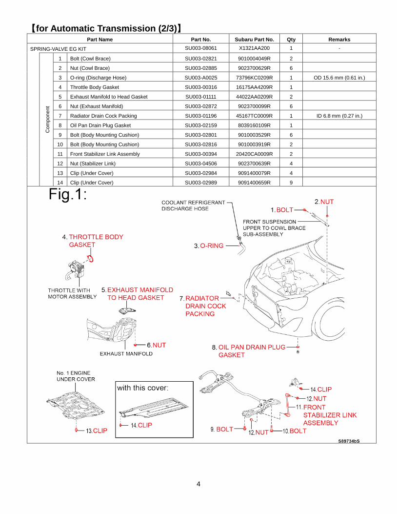
【for Automatic Transmission (2/3)】 Part Name Part No. Subaru Part No. Qty Remarks
SPRING-VALVE EG KIT SU003-08061 X1321AA200 1 -
Com
pone
nt
1 Bolt (Cowl Brace) SU003-02821 9010004049R 2
2 Nut (Cowl Brace) SU003-02885 9023700629R 6
3 O-ring (Discharge Hose) SU003-A0025 73796KC0209R 1 OD 15.6 mm (0.61 in.)
4 Throttle Body Gasket SU003-00316 16175AA4209R 1
5 Exhaust Manifold to Head Gasket SU003-01111 44022AA0209R 2
6 Nut (Exhaust Manifold) SU003-02872 9023700099R 6
7 Radiator Drain Cock Packing SU003-01196 45167TC0009R 1 ID 6.8 mm (0.27 in.)
8 Oil Pan Drain Plug Gasket SU003-02159 8039160109R 1
9 Bolt (Body Mounting Cushion) SU003-02801 9010003529R 6
10 Bolt (Body Mounting Cushion) SU003-02816 9010003919R 2
11 Front Stabilizer Link Assembly SU003-00394 20420CA0009R 2
12 Nut (Stabilizer Link) SU003-04506 9023700639R 4
13 Clip (Under Cover) SU003-02984 9091400079R 4
14 Clip (Under Cover) SU003-02989 9091400659R 9
5
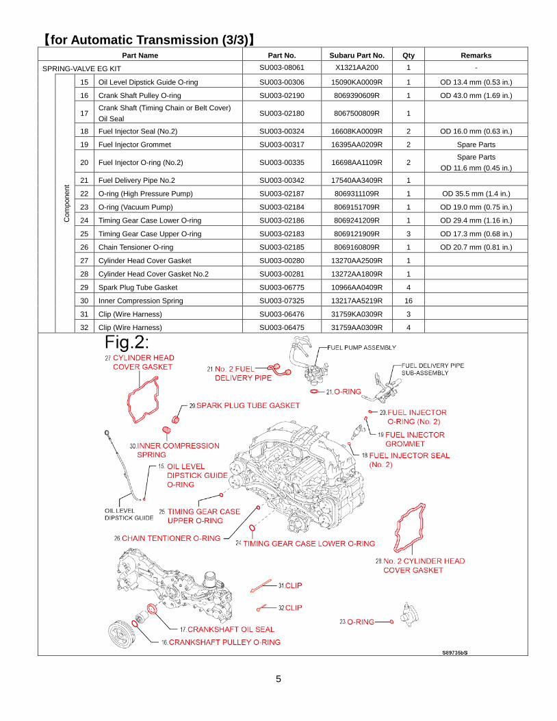
【for Automatic Transmission (3/3)】 Part Name Part No. Subaru Part No. Qty Remarks
SPRING-VALVE EG KIT SU003-08061 X1321AA200 1 -
Com
pone
nt
15 Oil Level Dipstick Guide O-ring SU003-00306 15090KA0009R 1 OD 13.4 mm (0.53 in.)
16 Crank Shaft Pulley O-ring SU003-02190 8069390609R 1 OD 43.0 mm (1.69 in.)
17 Crank Shaft (Timing Chain or Belt Cover) Oil Seal
SU003-02180 8067500809R 1
18 Fuel Injector Seal (No.2) SU003-00324 16608KA0009R 2 OD 16.0 mm (0.63 in.)
19 Fuel Injector Grommet SU003-00317 16395AA0209R 2 Spare Parts
20 Fuel Injector O-ring (No.2) SU003-00335 16698AA1109R 2 Spare Parts
OD 11.6 mm (0.45 in.) 21 Fuel Delivery Pipe No.2 SU003-00342 17540AA3409R 1
22 O-ring (High Pressure Pump) SU003-02187 8069311109R 1 OD 35.5 mm (1.4 in.)
23 O-ring (Vacuum Pump) SU003-02184 8069151709R 1 OD 19.0 mm (0.75 in.)
24 Timing Gear Case Lower O-ring SU003-02186 8069241209R 1 OD 29.4 mm (1.16 in.)
25 Timing Gear Case Upper O-ring SU003-02183 8069121909R 3 OD 17.3 mm (0.68 in.)
26 Chain Tensioner O-ring SU003-02185 8069160809R 1 OD 20.7 mm (0.81 in.)
27 Cylinder Head Cover Gasket SU003-00280 13270AA2509R 1
28 Cylinder Head Cover Gasket No.2 SU003-00281 13272AA1809R 1
29 Spark Plug Tube Gasket SU003-06775 10966AA0409R 4
30 Inner Compression Spring SU003-07325 13217AA5219R 16
31 Clip (Wire Harness) SU003-06476 31759KA0309R 3
32 Clip (Wire Harness) SU003-06475 31759AA0309R 4
6
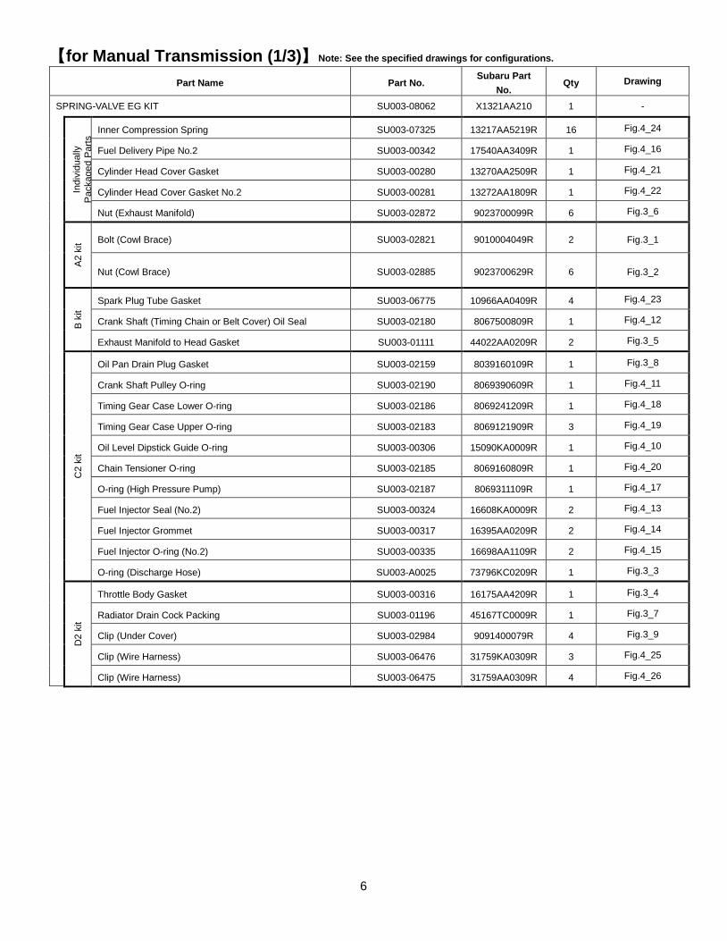
【for Manual Transmission (1/3)】Note: See the specified drawings for configurations.
Part Name Part No. Subaru Part
No. Qty Drawing
SPRING-VALVE EG KIT SU003-08062 X1321AA210 1 -
Indi
vidu
ally
Pa
ckag
ed P
arts
Inner Compression Spring SU003-07325 13217AA5219R 16 Fig.4_24
Fuel Delivery Pipe No.2 SU003-00342 17540AA3409R 1 Fig.4_16
Cylinder Head Cover Gasket SU003-00280 13270AA2509R 1 Fig.4_21
Cylinder Head Cover Gasket No.2 SU003-00281 13272AA1809R 1 Fig.4_22
Nut (Exhaust Manifold) SU003-02872 9023700099R 6 Fig.3_6
A2 k
it Bolt (Cowl Brace) SU003-02821 9010004049R 2 Fig.3_1
Nut (Cowl Brace) SU003-02885 9023700629R 6 Fig.3_2
B ki
t
Spark Plug Tube Gasket SU003-06775 10966AA0409R 4 Fig.4_23
Crank Shaft (Timing Chain or Belt Cover) Oil Seal SU003-02180 8067500809R 1 Fig.4_12
Exhaust Manifold to Head Gasket SU003-01111 44022AA0209R 2 Fig.3_5
C2
kit
Oil Pan Drain Plug Gasket SU003-02159 8039160109R 1 Fig.3_8
Crank Shaft Pulley O-ring SU003-02190 8069390609R 1 Fig.4_11
Timing Gear Case Lower O-ring SU003-02186 8069241209R 1 Fig.4_18
Timing Gear Case Upper O-ring SU003-02183 8069121909R 3 Fig.4_19
Oil Level Dipstick Guide O-ring SU003-00306 15090KA0009R 1 Fig.4_10
Chain Tensioner O-ring SU003-02185 8069160809R 1 Fig.4_20
O-ring (High Pressure Pump) SU003-02187 8069311109R 1 Fig.4_17
Fuel Injector Seal (No.2) SU003-00324 16608KA0009R 2 Fig.4_13
Fuel Injector Grommet SU003-00317 16395AA0209R 2 Fig.4_14
Fuel Injector O-ring (No.2) SU003-00335 16698AA1109R 2 Fig.4_15
O-ring (Discharge Hose) SU003-A0025 73796KC0209R 1 Fig.3_3
D2
kit
Throttle Body Gasket SU003-00316 16175AA4209R 1 Fig.3_4
Radiator Drain Cock Packing SU003-01196 45167TC0009R 1 Fig.3_7
Clip (Under Cover) SU003-02984 9091400079R 4 Fig.3_9
Clip (Wire Harness) SU003-06476 31759KA0309R 3 Fig.4_25
Clip (Wire Harness) SU003-06475 31759AA0309R 4 Fig.4_26
7
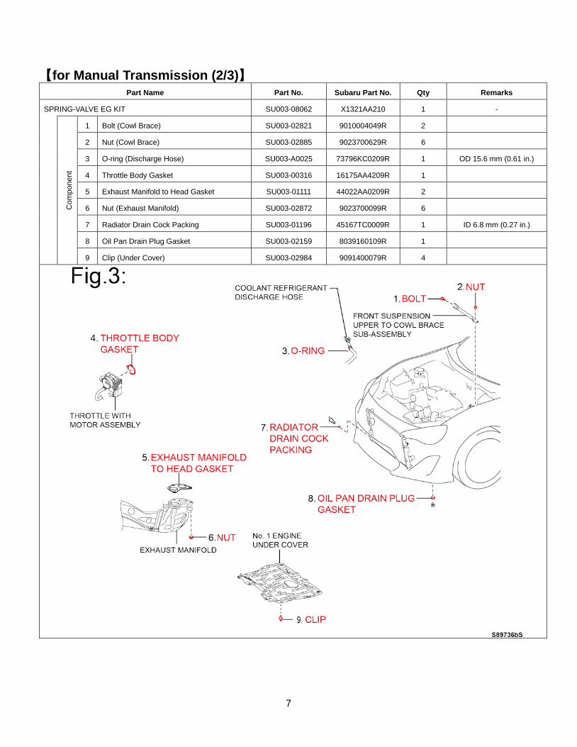
【for Manual Transmission (2/3)】 Part Name Part No. Subaru Part No. Qty Remarks
SPRING-VALVE EG KIT SU003-08062 X1321AA210 1 -
Com
pone
nt
1 Bolt (Cowl Brace) SU003-02821 9010004049R 2
2 Nut (Cowl Brace) SU003-02885 9023700629R 6
3 O-ring (Discharge Hose) SU003-A0025 73796KC0209R 1 OD 15.6 mm (0.61 in.)
4 Throttle Body Gasket SU003-00316 16175AA4209R 1
5 Exhaust Manifold to Head Gasket SU003-01111 44022AA0209R 2
6 Nut (Exhaust Manifold) SU003-02872 9023700099R 6
7 Radiator Drain Cock Packing SU003-01196 45167TC0009R 1 ID 6.8 mm (0.27 in.)
8 Oil Pan Drain Plug Gasket SU003-02159 8039160109R 1
9 Clip (Under Cover) SU003-02984 9091400079R 4
8
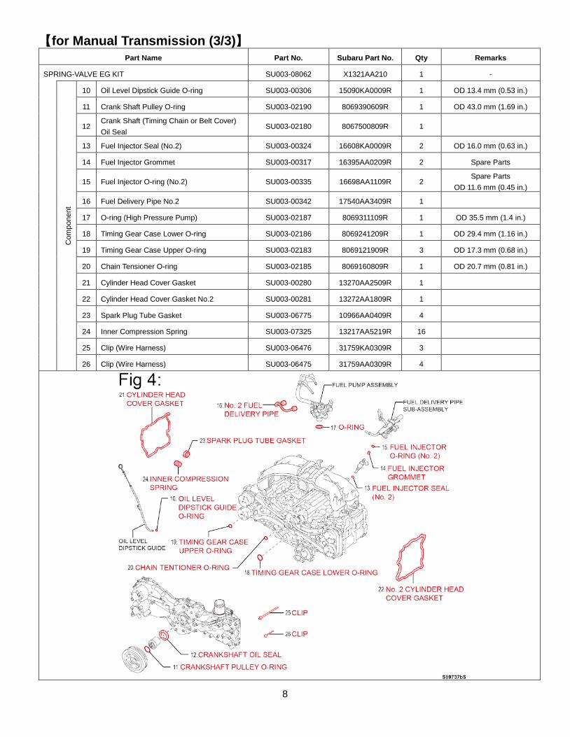
【for Manual Transmission (3/3)】 Part Name Part No. Subaru Part No. Qty Remarks
SPRING-VALVE EG KIT SU003-08062 X1321AA210 1 -
Com
pone
nt
10 Oil Level Dipstick Guide O-ring SU003-00306 15090KA0009R 1 OD 13.4 mm (0.53 in.)
11 Crank Shaft Pulley O-ring SU003-02190 8069390609R 1 OD 43.0 mm (1.69 in.)
12 Crank Shaft (Timing Chain or Belt Cover) Oil Seal
SU003-02180 8067500809R 1
13 Fuel Injector Seal (No.2) SU003-00324 16608KA0009R 2 OD 16.0 mm (0.63 in.)
14 Fuel Injector Grommet SU003-00317 16395AA0209R 2 Spare Parts
15 Fuel Injector O-ring (No.2) SU003-00335 16698AA1109R 2 Spare Parts
OD 11.6 mm (0.45 in.)
16 Fuel Delivery Pipe No.2 SU003-00342 17540AA3409R 1
17 O-ring (High Pressure Pump) SU003-02187 8069311109R 1 OD 35.5 mm (1.4 in.)
18 Timing Gear Case Lower O-ring SU003-02186 8069241209R 1 OD 29.4 mm (1.16 in.)
19 Timing Gear Case Upper O-ring SU003-02183 8069121909R 3 OD 17.3 mm (0.68 in.)
20 Chain Tensioner O-ring SU003-02185 8069160809R 1 OD 20.7 mm (0.81 in.)
21 Cylinder Head Cover Gasket SU003-00280 13270AA2509R 1
22 Cylinder Head Cover Gasket No.2 SU003-00281 13272AA1809R 1
23 Spark Plug Tube Gasket SU003-06775 10966AA0409R 4
24 Inner Compression Spring SU003-07325 13217AA5219R 16
25 Clip (Wire Harness) SU003-06476 31759KA0309R 3
26 Clip (Wire Harness) SU003-06475 31759AA0309R 4
9
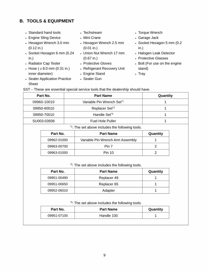
B. TOOLS & EQUIPMENT
• Standard hand tools • Engine Sling Device • Hexagon Wrench 3.0 mm
(0.12 in.) • Socket Hexagon 6 mm (0.24
in.) • Radiator Cap Tester • Hose (φ8.0 mm (0.31 in.)
inner diameter) • Sealer Application Practice
Sheet
• Techstream • Mini Crane • Hexagon Wrench 2.5 mm
(0.01 in.) • Union Nut Wrench 17 mm
(0.67 in.) • Protective Gloves • Refrigerant Recovery Unit • Engine Stand • Sealer Gun
• Torque Wrench • Garage Jack • Socket Hexagon 5 mm (0.2
in.) • Halogen Leak Detector • Protective Glasses • Bolt (For use on the engine
stand) • Tray
SST – These are essential special service tools that the dealership should have.
Part No. Part Name Quantity 09960-10010 Variable Pin Wrench Set*1 1
09950-60010 Replacer Set*2 1
09950-70010 Handle Set*3 1
SU003-03936 Fuel Hole Puller 1 *1: The set above includes the following tools.
Part No. Part Name Quantity 09962-01000 Variable Pin Wrench Arm Assembly 1
09963-00700 Pin 7 2
09963-01000 Pin 10 2
*2: The set above includes the following tools.
Part No. Part Name Quantity 09951-00490 Replacer 49 1
09951-00650 Replacer 65 1
09952-06010 Adapter 1
*3: The set above includes the following tools.
Part No. Part Name Quantity 09951-07100 Handle 100 1
10
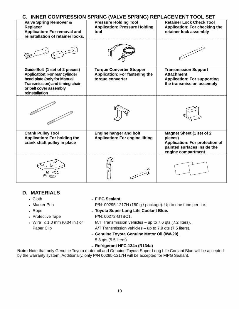
C. INNER COMPRESSION SPRING (VALVE SPRING) REPLACEMENT TOOL SET Valve Spring Remover & Replacer Application: For removal and reinstallation of retainer locks.
Pressure Holding Tool Application: Pressure Holding tool
Retainer Lock Check Tool Application: For checking the retainer lock assembly
Guide Bolt (1 set of 2 pieces) Application: For rear cylinder head plate (only for Manual Transmission) and timing chain or belt cover assembly reinstallation
Torque Converter Stopper Application: For fastening the torque converter
Transmission Support Attachment Application: For supporting the transmission assembly
Crank Pulley Tool Application: For holding the crank shaft pulley in place
Engine hanger and bolt Application: For engine lifting
Magnet Sheet (1 set of 2 pieces) Application: For protection of painted surfaces inside the engine compartment
D. MATERIALS • Cloth • Marker Pen • Rope • Protective Tape • Wire φ1.0 mm (0.04 in.) or
Paper Clip
• FIPG Sealant. P/N: 00295-1217H (150 g / package). Up to one tube per car.
• Toyota Super Long Life Coolant Blue. P/N: 00272-GTBC1. M/T Transmission vehicles – up to 7.6 qts (7.2 liters). A/T Transmission vehicles – up to 7.9 qts (7.5 liters).
• Genuine Toyota Genuine Motor Oil (0W-20). 5.8 qts (5.5 liters).
• Refrigerant HFC-134a (R134a)
Note: Note that only Genuine Toyota motor oil and Genuine Toyota Super Long Life Coolant Blue will be accepted by the warranty system. Additionally, only P/N 00295-1217H will be accepted for FIPG Sealant.

11
IV. BACKGROUND The valve springs located inside the engine of the affected vehicles may fracture, which may cause an abnormal noise or engine malfunction. In the worst case, this may result in the engine stalling during driving and the inability to restart the vehicle. An engine stall while driving at higher speeds could increase the risk of a crash.

12
V. WORK PROCEDURE A. COMPONENTS

13
14

15

16
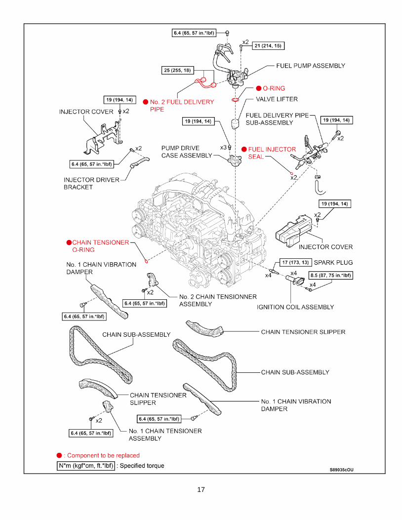
17

18
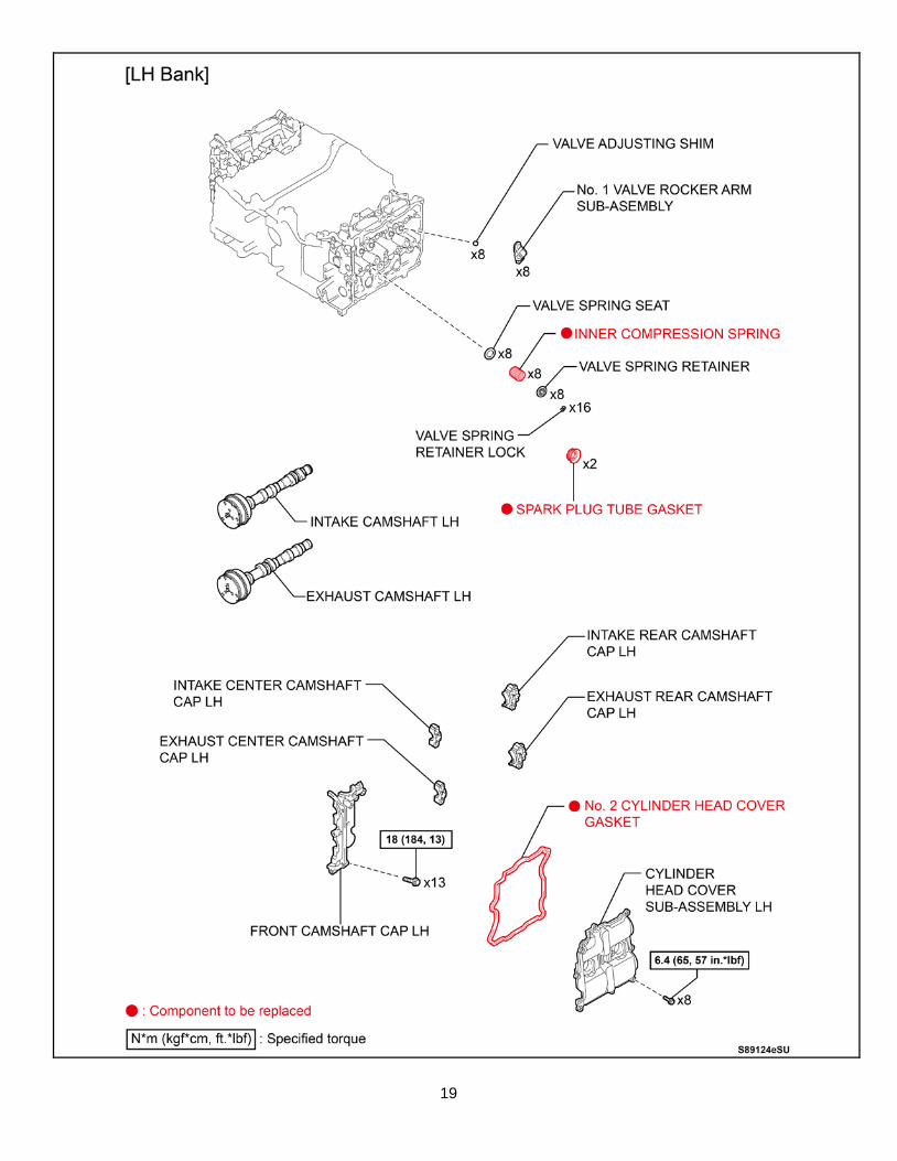
19
20
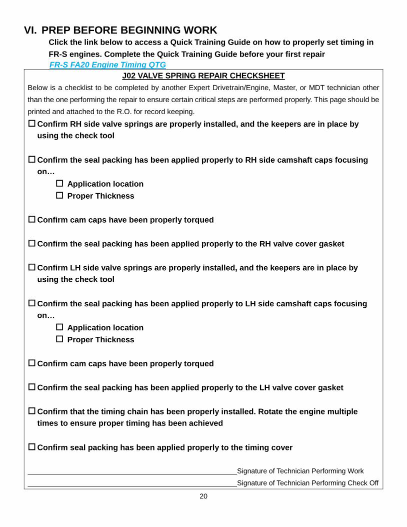
VI. PREP BEFORE BEGINNING WORK Click the link below to access a Quick Training Guide on how to properly set timing in FR-S engines. Complete the Quick Training Guide before your first repair
FR-S FA20 Engine Timing QTG J02 VALVE SPRING REPAIR CHECKSHEET
Below is a checklist to be completed by another Expert Drivetrain/Engine, Master, or MDT technician other than the one performing the repair to ensure certain critical steps are performed properly. This page should be printed and attached to the R.O. for record keeping.
Confirm RH side valve springs are properly installed, and the keepers are in place by using the check tool
Confirm the seal packing has been applied properly to RH side camshaft caps focusing on…
Application location Proper Thickness
Confirm cam caps have been properly torqued
Confirm the seal packing has been applied properly to the RH valve cover gasket Confirm LH side valve springs are properly installed, and the keepers are in place by
using the check tool Confirm the seal packing has been applied properly to LH side camshaft caps focusing
on… Application location Proper Thickness
Confirm cam caps have been properly torqued
Confirm the seal packing has been applied properly to the LH valve cover gasket Confirm that the timing chain has been properly installed. Rotate the engine multiple
times to ensure proper timing has been achieved Confirm seal packing has been applied properly to the timing cover Signature of Technician Performing Work Signature of Technician Performing Check Off
21
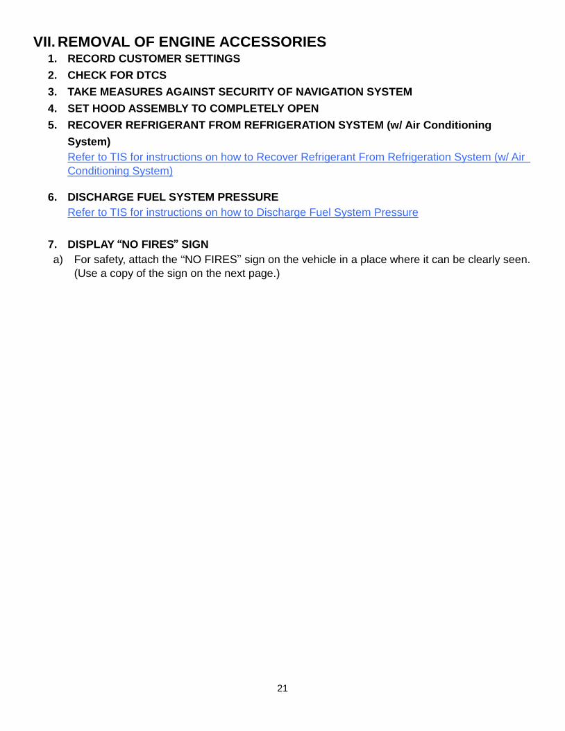
VII. REMOVAL OF ENGINE ACCESSORIES 1. RECORD CUSTOMER SETTINGS 2. CHECK FOR DTCS 3. TAKE MEASURES AGAINST SECURITY OF NAVIGATION SYSTEM 4. SET HOOD ASSEMBLY TO COMPLETELY OPEN 5. RECOVER REFRIGERANT FROM REFRIGERATION SYSTEM (w/ Air Conditioning
System) Refer to TIS for instructions on how to Recover Refrigerant From Refrigeration System (w/ Air Conditioning System)
6. DISCHARGE FUEL SYSTEM PRESSURE
Refer to TIS for instructions on how to Discharge Fuel System Pressure
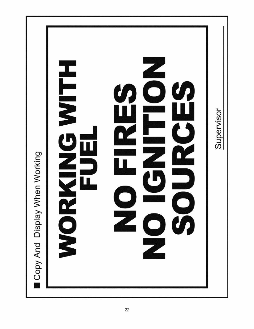
7. DISPLAY “NO FIRES” SIGN a) For safety, attach the “NO FIRES” sign on the vehicle in a place where it can be clearly seen.
(Use a copy of the sign on the next page.)
22
23
8. REMOVE FUEL TANK CAP ASSEMBLY
DO NOT reinstall the cap until instructed to prevent fuel leakage caused by a pressure rise inside the fuel tank.
9. FULLY OPEN DRIVER AND PASSENGER SIDE WINDOWS
Be sure to fully open the windows, as they are provided with a mechanism that electrically crimps the glass to the weatherstrip when the window is completely closed. Damage to the weatherstrip may occur when a door is opened or closed while the window is completely closed, if this mechanism does not operate due to disconnection of the battery.
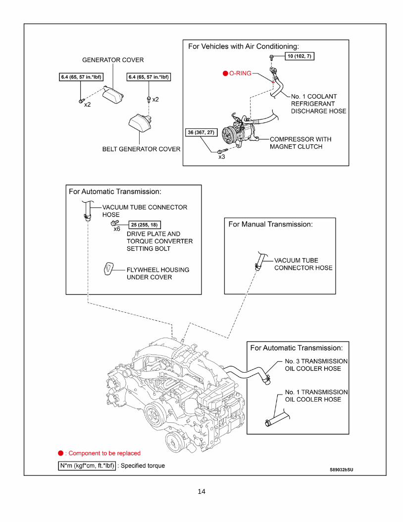
10. DISCONNECT CABLE FROM BATTERY NEGATIVE TERMINAL 11. DRAIN ENGINE OIL 12. DRAIN ENGINE COOLANT 13. REMOVE FRONT SUSPENSION UPPER TO COWL BRACE SUB-ASSEMBLIES RH AND LH 14. REMOVE AIR CLEANER CAP WITH AIR CLEANER HOSE 15. REMOVE GENERATOR COVER 16. REMOVE BELT GENERATOR COVER 17. REMOVE ENGINE OIL LEVEL DIPSTICK GUIDE 18. REMOVE FAN AND GENERATOR V BELT
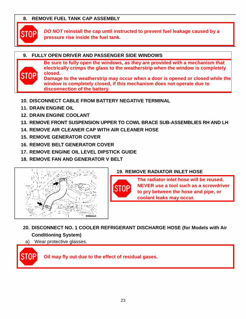
19. REMOVE RADIATOR INLET HOSE
The radiator inlet hose will be reused. NEVER use a tool such as a screwdriver to pry between the hose and pipe, or coolant leaks may occur.
20. DISCONNECT NO. 1 COOLER REFRIGERANT DISCHARGE HOSE (for Models with Air Conditioning System)
a) Wear protective glasses.
Oil may fly out due to the effect of residual gases.
24
b) Remove the bolt, and with a cloth covering it, slowly disconnect the discharge hose.
Oil may fly out due to the effect of residual gases.
c) Remove the O-ring from the No. 1 cooler
refrigerant discharge hose.
d) Destroy the removed O-ring, and then store it in a separate container so as not to reinstall it in error.
e) Attach protective tape to the disconnected hose
and compressor fittings to prevent foreign matter, fluids, etc., from contaminating.
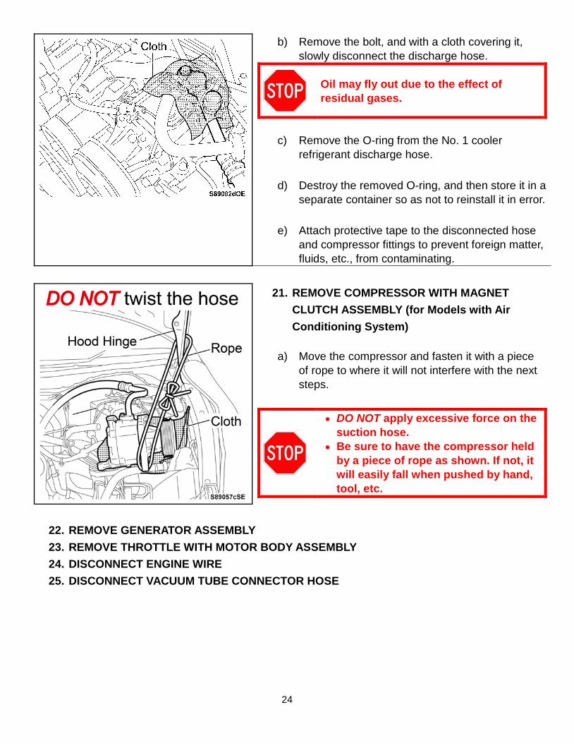
21. REMOVE COMPRESSOR WITH MAGNET CLUTCH ASSEMBLY (for Models with Air Conditioning System)
a) Move the compressor and fasten it with a piece
of rope to where it will not interfere with the next steps.
• DO NOT apply excessive force on the suction hose.
• Be sure to have the compressor held by a piece of rope as shown. If not, it will easily fall when pushed by hand, tool, etc.
22. REMOVE GENERATOR ASSEMBLY 23. REMOVE THROTTLE WITH MOTOR BODY ASSEMBLY 24. DISCONNECT ENGINE WIRE 25. DISCONNECT VACUUM TUBE CONNECTOR HOSE

25
26. SEPARATE AIR FUEL RATIO SENSOR a) Remove the 2 bolts. b) Disengage the 2 clamps by pressing in the claws
one side at a time on each with a flathead screwdriver, and separate the wire harness.
c) Disconnect the connector.
27. SEPARATE OXYGEN SENSOR a) Disconnect the connector. b) Pull the 2 clips out straight and separate the
oxygen sensor.
28. REMOVE FRONT TIRES 29. REMOVE No 1 ENGINE UNDER COVER 30. REMOVE NO. 2 ENGINE UNDER COVER 31. REMOVE REAR ENGINE UNDER COVER LH AND RH (w/ Floor Under Cover)
26
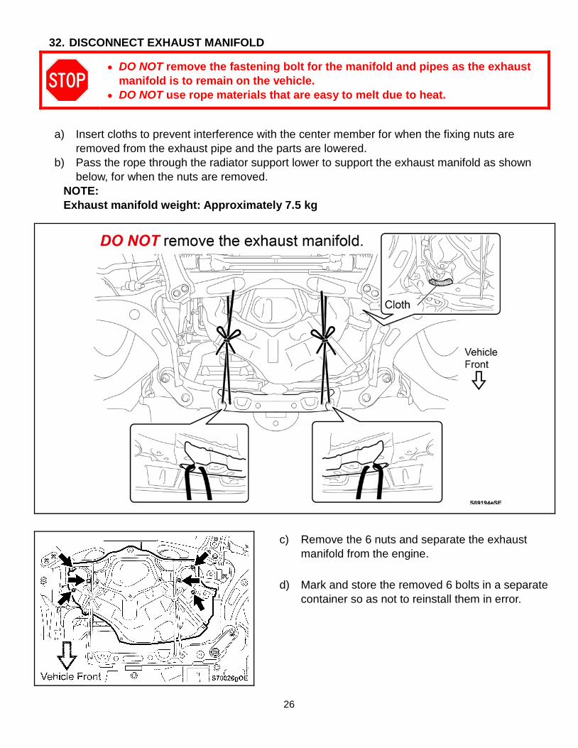
32. DISCONNECT EXHAUST MANIFOLD
• DO NOT remove the fastening bolt for the manifold and pipes as the exhaust manifold is to remain on the vehicle.
• DO NOT use rope materials that are easy to melt due to heat.
a) Insert cloths to prevent interference with the center member for when the fixing nuts are
removed from the exhaust pipe and the parts are lowered. b) Pass the rope through the radiator support lower to support the exhaust manifold as shown
below, for when the nuts are removed. NOTE: Exhaust manifold weight: Approximately 7.5 kg
c) Remove the 6 nuts and separate the exhaust manifold from the engine.
d) Mark and store the removed 6 bolts in a separate
container so as not to reinstall them in error.

27
33. DISCONNECT RADIATOR OUTLET HOSE a) Protect the manifold with a cloth to prevent
coolant from getting in the exhaust manifold. b) Disconnect the radiator outlet hose.
c) Protect the disconnected water outlet by covering the opening with a plastic bag as shown.
Be sure to protect the water outlet as oil may enter the outlet when disassembling the engine.
34. DISCONNECT GROUNDED CABLE 35. REMOVE FRONT STABILIZER LINK ASSEMBLIES RH AND LH (for Automatic
Transmission)
36. REMOVE FRONT STABILIZER BARS RH AND LH (for Automatic Transmission)
a) Remove only 1 clip, each from the left and right engine under covers.
28
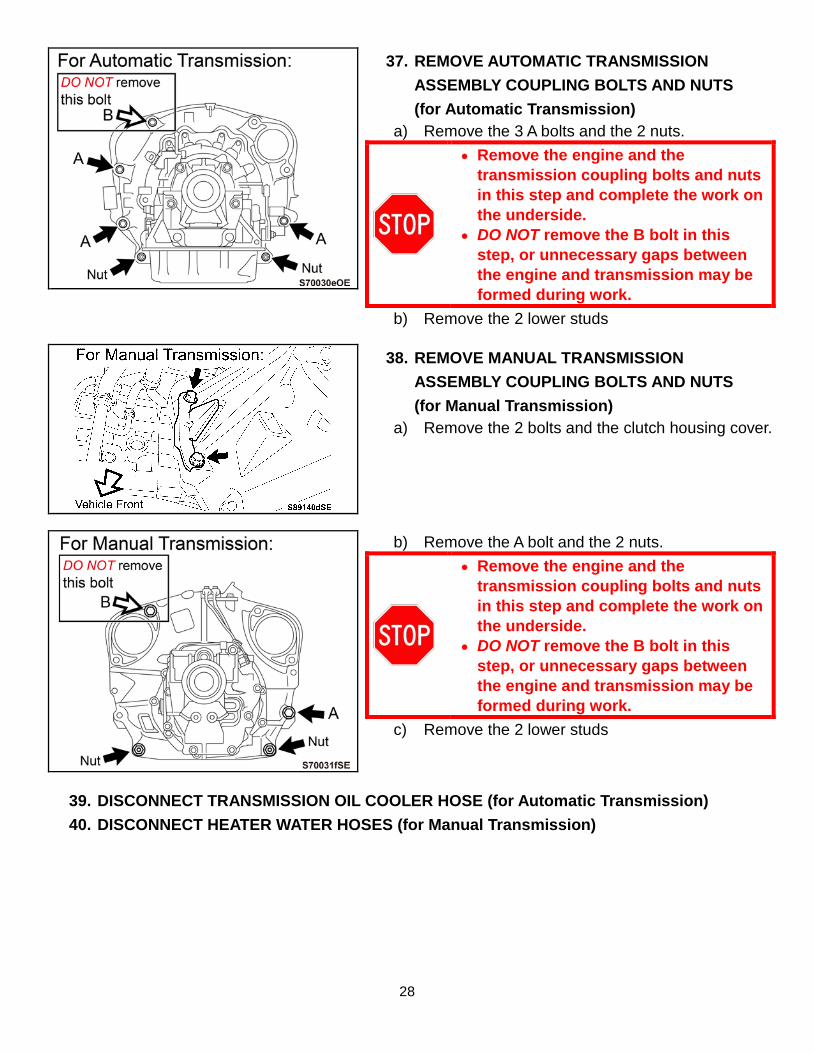
37. REMOVE AUTOMATIC TRANSMISSION ASSEMBLY COUPLING BOLTS AND NUTS (for Automatic Transmission)
a) Remove the 3 A bolts and the 2 nuts.
• Remove the engine and the transmission coupling bolts and nuts in this step and complete the work on the underside.
• DO NOT remove the B bolt in this step, or unnecessary gaps between the engine and transmission may be formed during work.
b) Remove the 2 lower studs
38. REMOVE MANUAL TRANSMISSION ASSEMBLY COUPLING BOLTS AND NUTS (for Manual Transmission)
a) Remove the 2 bolts and the clutch housing cover.
b) Remove the A bolt and the 2 nuts.
• Remove the engine and the transmission coupling bolts and nuts in this step and complete the work on the underside.
• DO NOT remove the B bolt in this step, or unnecessary gaps between the engine and transmission may be formed during work.
c) Remove the 2 lower studs
39. DISCONNECT TRANSMISSION OIL COOLER HOSE (for Automatic Transmission) 40. DISCONNECT HEATER WATER HOSES (for Manual Transmission)

29
41. SEPARATE FRONT CROSS MEMBER SUB ASSEMBLY FROM ENGINE a) Remove the 2 engine mount nuts from the
cross member sub-assembly
42. REMOVE STARTER ASSEMBLY 43. REMOVE FLYWHEEL HOUSING UNDER COVER (for Automatic Transmission)
44. REMOVE DRIVE PLATE AND TORQUE CONVERTER SETTING BOLTS (for Automatic Transmission) (Requires 2 Workers)
a) Using SST, hold the crankshaft pulley in place. SST:09960-10010
(09962-01000, 09963-01000)
b) Set a piece of cloth on the service hole to prevent the bolts from falling in.
c) Remove the 6 bolts through the service hole, while another worker holds the crankshaft pulley.
DO NOT drop the bolts or tools.
d) Remove the cloth.
45. ATTACH TORQUE CONVERTER STOPPER (for Automatic Transmission)
NOTE: The torque converter stopper is a tool for prevention of fluid leakage if the torque converter detaches together with the engine when the engine block is separated from the transmission assembly.
a) Loosen (DO NOT remove) the bolt for the tool.
30
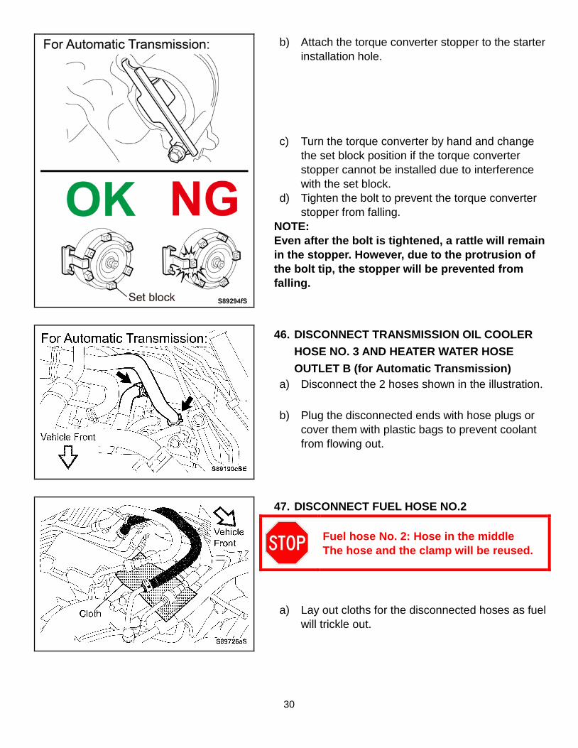
b) Attach the torque converter stopper to the starter installation hole.
c) Turn the torque converter by hand and change
the set block position if the torque converter stopper cannot be installed due to interference with the set block.
d) Tighten the bolt to prevent the torque converter stopper from falling.
NOTE: Even after the bolt is tightened, a rattle will remain in the stopper. However, due to the protrusion of the bolt tip, the stopper will be prevented from falling.
46. DISCONNECT TRANSMISSION OIL COOLER HOSE NO. 3 AND HEATER WATER HOSE OUTLET B (for Automatic Transmission)
a) Disconnect the 2 hoses shown in the illustration.
b) Plug the disconnected ends with hose plugs or cover them with plastic bags to prevent coolant from flowing out.
47. DISCONNECT FUEL HOSE NO.2
Fuel hose No. 2: Hose in the middle The hose and the clamp will be reused.
a) Lay out cloths for the disconnected hoses as fuel will trickle out.