Embed Size (px)
Citation preview

Technical Guidelines & Information for
Stone Construction In Uttarakhand
Disaster Management and Mitigation Center, Dehradun, Govt. of Uttarakhand.

Technical Guidelines & Information for Stone Construction In Uttarakhand
Prepared as a part of project titled
Taking Traditional Technologies Forward – Preparing for Disasters
Guidelines Steering CommitteePrincipal Secretary, Disaster Management, GoUK – Chair personProf. A.S.Arya, Former Seismic Advisor to GoI – MemberProf. D.K.Paul, Dept. of Earthquake Engineering, IIT, Roorkee – Member Shri Rajendra Desai, Hon. Jt. Director, NCPDP, Ahmedabad – Member Shri Pawan Jain, Architect, Dehradun – Member Dr. Piyoosh Rautela, Executive Director, DMMC, Dehradun – Member/Secretary
Guidelines Review CommitteeProf.K.S.Jagadish, Former Professor IISc, Banglore – Chair personProf. Y.K.Singh, Dept. of Earthquake Engineering, IIT, Roorkee – Member Dr. Girish Joshi, Senior Executive, DMMC, Dehradun – Member/Secretary
Technical Guideline for Stone Construction in Uttarakhand I
Prepared ByProject Team: Rajendra Desai, Rupal Desai, Pawan Jain,
R.K.Mukerji, Harshad Talpada NCPDP, 103 Antariksh, Panjarapol Cross Roads, Ahmedabad, GUJ 380015
Tel: 079 2630 9712 E-mail: [email protected]

Foreword
From DMMC
Technical Guideline for Stone Construction in Uttarakhand ii

PrefaceState of Uttarakhand is known to be seismically one of the most active regions of the
country. In recent times the state was hit by two moderate earthquakes. On October 19,
1991 an earthquake of 6.4 on Richter scale had struck in the vicinity of Uttarkashi town
and on March 29, 1999 of 6.8 had struck in the vicinity of Chomoli town. Both
earthquakes caused extensive damage to the buildings having stone walls and Pathal
roof.
The stone construction in the state has been transforming over the past several
decades. During this period the traditional safety features such as the timber bands,
vertical timber stiffeners and the timber upper storey gradually disappeared as access
to good quality timber became restricted. During this period, the adherence to the basic
rules of stone construction too faltered. This led to drastic decrease in the seismic
resistance of the stone structures which resulted in to wide-scale damage in the past
two earthquakes.
This damage badly shook peoples' confidence in the stone construction. As a result
people began shifting from stone construction to that based on steel, cement and brick
that they perceive to be safer. This has been at the cost of many important benefits of the
traditional construction that people had enjoyed for centuries.
This document is made with the objective of guiding all those involved in the
construction of buildings with stone including the engineers, contractors, building
artisans and people, so that they are able to construct stone buildings that will resist
future earthquakes and restore peoples' confidence in traditional stone construction.
It must be added that using good quality cement mortar in stone masonry is one of the
important requirements. However, if mud mortar is desired to be used for any reason,
reasonable earthquake resistance can be achieved by using appropriate measures. In
place of mud mortar, the guidelines also cover other affordable alternatives that use
cement in combination with lime while making mortar with sand or one that uses cement
to stabilize mud. Similarly, the earthquake resisting features include those made of
concrete and steel, as also those made from available timber.
It is hoped that all those involved in construction take full care in using the necessary
disaster safety elements in the new construction, whether for housing or for important
buildings such as schools, public health facility or community halls.
Finally, in today's context of global warming and climate change, it is important that
virtues of the traditional building construction that predominantly use the local materials
do not use large quantities of energy in their production and do not have to be
transported over long distances are recognized and promoted.
Dehradun Project TeamFebruary 28, 2011
Technical Guideline for Stone Construction in Uttarakhand iii

Acknowledgement
First and foremost we acknowledge the support that we received from Disaster
Management and Mitigation Centre, Government of Uttarakhand, notably from
Dr.Piyoosh Rautela and Dr. Girish Joshi. Without their initiatives in coordinating the
process of reviews and finalization the time taken in creating this document would have
been much more.
Prof. K.S.Jagadish from Banglore and Prof. Y.K.Singh of IIT- Roorkee were most
positive and supportive during the review process and helped improve the content of the
initial draft through their invaluable input.
Finally, it was the detailed and painstaking scrutiny by Prof.A.S.Arya and Prof. D.K.Paul
that helped us make a thorough technical document that is easy to comprehend.
In addition, we are thankful to a large number of people across the state that we met
during our field study that helped us acquire a reasonable understanding of the
vernacular building systems in the state and the transformations taking place.
Finally, we also acknowledge The Ford Foundation for initiating a multi-state project for
studying the traditional building systems and developing suitable building typologies
based on these, which is also integrated with the scientific validation of the building
practices and preparation of the guidelines.
Ahmedabad Project Team
February 28, 2011
Technical Guideline for Stone Construction in Uttarakhand ivi
Glossary
Word Meaning
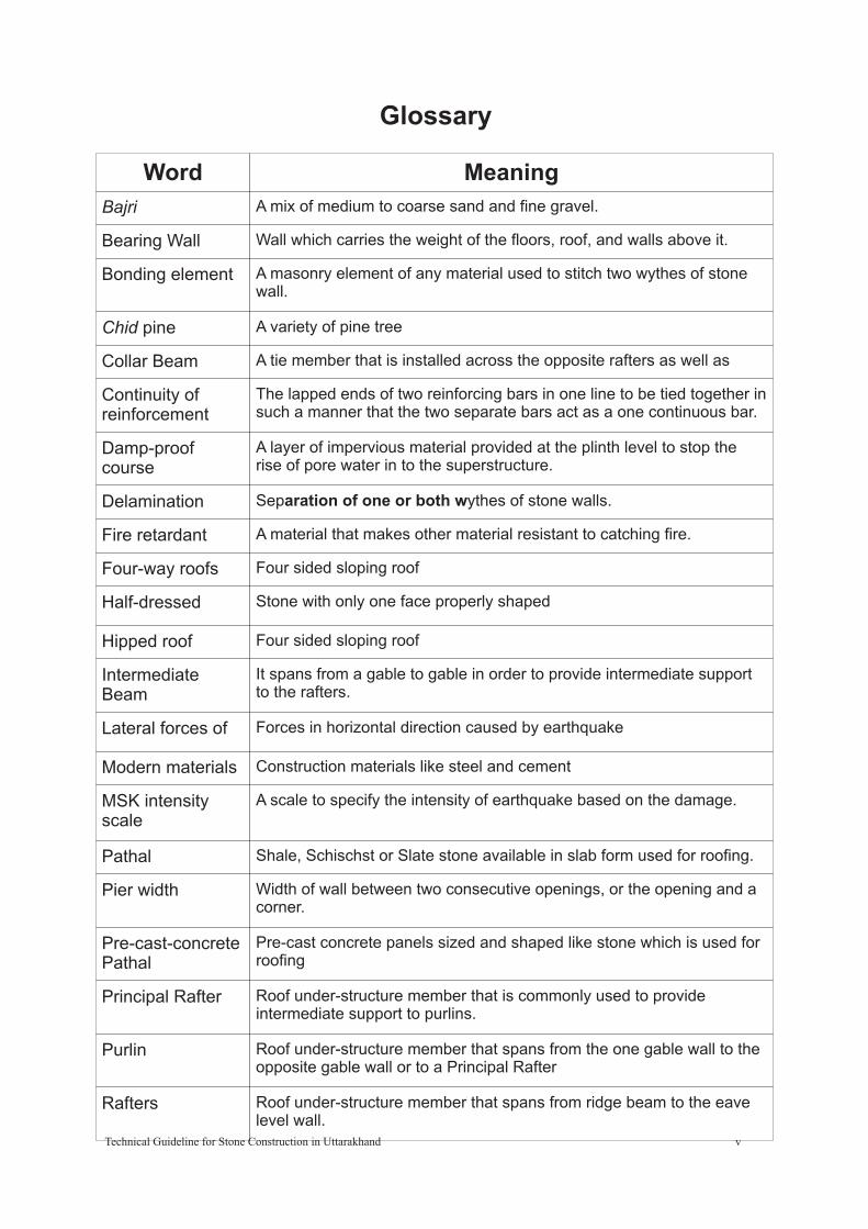
Bajri A mix of medium to coarse sand and fine gravel.
Bearing Wall Wall which carries the weight of the floors, roof, and walls above it.
Bonding element A masonry element of any material used to stitch two wythes of stone wall.
Chid pine A variety of pine tree
Collar Beam A tie member that is installed across the opposite rafters as well as
Continuity of reinforcement
The lapped ends of two reinforcing bars in one line to be tied together in such a manner that the two separate bars act as a one continuous bar.
Damp-proof course
A layer of impervious material provided at the plinth level to stop the rise of pore water in to the superstructure.
Delamination Separation of one or both wythes of stone walls.
Fire retardant A material that makes other material resistant to catching fire.
Four-way roofs Four sided sloping roof
Half-dressed Stone with only one face properly shaped
Hipped roof Four sided sloping roof
Intermediate Beam
It spans from a gable to gable in order to provide intermediate support to the rafters.
Lateral forces of Forces in horizontal direction caused by earthquake
Modern materials Construction materials like steel and cement
MSK intensity scale
A scale to specify the intensity of earthquake based on the damage.
Pathal Shale, Schischst or Slate stone available in slab form used for roofing.
Pier width Width of wall between two consecutive openings, or the opening and a corner.
Pre-cast-concrete Pathal
Pre-cast concrete panels sized and shaped like stone which is used for roofing
Principal Rafter Roof under-structure member that is commonly used to provide intermediate support to purlins.
Purlin Roof under-structure member that spans from the one gable wall to the opposite gable wall or to a Principal Rafter
Rafters Roof under-structure member that spans from ridge beam to the eave level wall.
Technical Guideline for Stone Construction in Uttarakhand v

Word Meaning
Random rubble masonry
Stones of different and irregular shape fitted over each other to create masonry.
Ringaal Cane like grass that grows in the hills.
Roding Compacting concrete by means of rods to eliminate air bubbles.
Seismic Band A Reinforced Concrete or Reinforced Brick or Timber runner provided in the walls to tie them together, and to impart horizontal bending strength in them.
Seismic feature A particular strengthening arrangement for reinforcing of masonry buildings to enhance resistance against seismic forces.
Seismic zone An area with a specific seismic hazard level as classified in IS 1893:1984
Shear resisting capacity
The capacity of the wall to resist lateral force in its own plane.
Stabilization of mud
Mud mixed with some material that helps preserve its strength in presence of water or reduces engross of water into mud
Stonecrete Block Concrete block with large stones surrounded by the matrix of concrete.
Through-Stone Stone of length equal to the thickness of wall and placed across wall's thickness
Traditional construction
The construction system based primarily on locally available materials evolved by the people without input of engineers and architects.
Two-way roofs Two sided sloping roof
Urad daal A variety of lintle used mainly as a food item
Vulnerable Building too weak to withstand forces of natural hazards
Wythe Vertical Face (vertical layer) of stone wall
Glossary
Technical Guideline for Stone Construction in Uttarakhand vi

Abbreviations
Abbreviation Full form Abbreviation Full form
lvl. level kg. Kilogram
AC Asbestos cement km. Kilometer
Approx. Approximately lbs. pounds
BB Burnt brick liq. liquid
BBCM Burnt brick in cement mortar
m. Meter
BBMM Burnt brick in mud mortar
max. Maximum
BIS Bureau of Indian Standards
min. Minimum, minute
Bldg. Building mm. Millimeter
CB Concrete Block MPT Mangalore Pattern tile
CBRI Central Building Research Institute
MS Mild steel
Cem. cement No., no., nos. Number, Numbers
CGI Corrugated Galvanized Iron
OPC Ordinary Portland cement
CM Cement Mortar PC Pre-cast concrete
cm. Centimeter PCRC Pre-cast reinforced concrete
cu. Cubic PPC Pozzolonic Portland cement
cum. Cubic meter PVC Poly Vinyl Chloride
CWM Chicken wire mesh RB Reinforced brick
dia. Diameter RC Reinforced concrete
dist. Distance reinf. Reinforcement
ea. Each rmt. Running meter
eqk. Earthquake RR Random rubble
fdn. Foundation sec. Second
ft. Foot, feet sft. Square foot
ga. Gauge smt. Square meter
GI Galvanized Iron sq. Square
gr. Ground ssm. seismic
horz. Horizontal st. storey
hr. Hour UCRC Un-coursed rubble masonry in cement mortar
HSD High Strength Deformed
UCRM Un-coursed rubble masonry in mud mortar
ht. Height vert. Vertical
in. Inch wt. Weight
Itr. liter WWM Welded wire mesh
yds. Yards
Technical Guideline for Stone Construction in Uttarakhand vii

Contents
No. Topic Page No.
1 Introduction 01.1 Traditional building system of Uttarakhand 01.2 Impact of recent earthquakes 0
2 Objectives
3 Scope of the Guidelines
4. Options for stone walls4.1 Types of Masonry used in different parts of Uttarakhand 04.2 Alternatives for wall masonry 0
5 Options for roof and floor5.1 Pathal roofs & timber floors
6. Required Earthquake safety provisions for stone construction (Low Strength Masonry)
6.1 Building categorization6.2 Measure for achieving seismic safety
7 Siting & Foundation7.1 Siting7.2 Foundations
8 Treatment at plinth level
9. Stone masonry walls using cement mortar9.1 Construction Control 009.2 Control on No. of Storeys, Storey Height and Wall Length 009.3 Control on Door Window Openings in Walls 009.4 Required Earthquake Safety Provisions 009.5 Seismic Bands 009.6 Vertical Reinforcement in Walls 00
10 Stone Masonry Using Mud Mortar, or 00Weak Lime, or Weak Cement Mortar
10.1 General 0010.2 Construction Control 0010.3 Controls on Wall Length and Building Height 0010.4 No. of Storeys 0010.5 Controls on Openings in Load Bearing Walls 0010.6 Required Earthquake Safety Provisions 00
Technical Guideline for Stone Construction in Uttarakhand viii

10.7 Vertical Reinforcement in Walls 0010.8 Vertical Timber Elements for Vertical Reinforcements 0010.9 Water Proofing 00
11 Guidelines for Earthquake Resisting Timber 00Floor Construction)
11.1 Intermediate Floors 0011.2 Floor Joists 0011.3 Decking 0011.4 Diaphragm made of Struts & Bracings 00
12 Guidelines for Earthquake Resisting 00Pathal Roof Construction
12.1 Roof Types 0012.2 Different Roof Configurations 0012.3 Principal Rafter 0012.4 Purlins 0012.5 Intermediate Beam 0012.6 Rafters 0012.7 Pathal Supports 0012.8 Pathal 0012.9 Installation of Struts and Diagonal Bracings 0012.10 Installation of Ridge Truss 00
AnnexureAnnexure A - ReferencesAnnexure B - Difficulties experienced in building stone houseAnnexure C- Things you should know about stone masonry walls.Annexure D - Things you should know about Pathal roofAnnexure E - Timber preservation treatment
Technical Guideline for Stone Construction in Uttarakhand ix

1. Introduction
1.1 Traditional building system of UttarakhandPeople have been constructing stone buildings for their house and other service needs for hundreds of years in the hill areas of Uttarakhand, since stone has been the most abundantly found building material. Not only have they been using the stone for walls, but also for roofing. Timber, being the second most abundantly found material in the area, has also been in use in combination with stone for roof construction. In other words, the construction system based primarily on these two materials has been the backbone of the traditional construction of the region.
1.2 Impact of recent earthquakesIn the decade of 1990's the state witnessed two destructive earthquakes. Both the earthquakes witnessed severe damage to many stone buildings. As a consequence, peoples' confidence in the traditional construction got badly shaken. This resulted in many house-owners switching over to modern cement, steel and brick based construction which many find expensive.
These guidelines will be helpful in designing earthquake resistant buildings with stone as the principal material in all parts of the State of Uttarakhand including those falling in the Seismic Zones IV and V.
2. Objectives
The main objective of this guidelines is to illustrate the earthquake resisting construction measures that should be adopted in the traditional stone construction practice in accordance with the Seismic Zoning map of Uttarakhand using the building construction standards adopted in India, namely IS: 4326: 1993, second revision BIS 2002 and IS: 13828 of 1993
According to the Seismic Zoning Map of Uttarakhand (Fig. 2.1) most areas of Uttarakhand state are situated in the following seismic zones.Zone V: MSK intensity IX or higher earthquake is probable to occur.Zone IV: MSK Intensity VIII earthquake is probable to occur.
Other Hazards: In the plains, along the southern boundary of the state, as per the Wind Speed Zone map from the Vulnerability Atlas of Uttarakhand the wind speeds can reach high enough (47m/s) to bring moderate damage risk. In the hills this hazard is significantly less with maximum wind speeds of 39m/s.
Floods hazard can be present in isolated low spots, mainly due to flash flood phenomena or inundation due to inadequate drainage.
In the mountains, in areas where the hillside is unstable, the landslides also is a major hazards,
The recommendations contained herein are based on the abovementioned probable earthquake intensities for the design of buildings according to the codes. New construction of buildings will be safe if it would be in accordance with the specified intensities.
Technical Guideline for Stone Construction in Uttarakhand 01

**Figure 2.1 Seismic Zone Map of Uttarakhand
Ref: Vulnerability Atlas of Uttarakhand, BMTPC.
Technical Guideline for Stone Construction in Uttarakhand 02

3. Scope of the Guide
These guidelines cover the houses having load-bearing masonry walls of stone with pitched roof of Pathal having timber understructure and the intermediate timber floor, both resting on the walls in the hill regions of Uttarakhand State. Figures 3.1 and 3.2 show the important building components of a typical stone based construction. The recommendations cover the most likely hazards in the regions. The provisions for the earthquake resisting features are made for Seismic Intensities MSK greater than or equal to IX, and VIII as appropriate for the earthquake damage prone Zones V and IV respectively. Construction of walls using mud mortar as well as cement mortar is dealt with in this document. In any room the length of walls built in cement mortar shall be no greater than 7.0 meters and those built in mud mortar shall be no greater than 5.0 meters.
4. Options for Stone Walls
The following types of masonry are normally used in stone-building construction.
4.1. Types of Masonry used in different parts of Uttarakhand
· Random rubble masonry There are different types of Random Rubble masonry as shown below.
i. Partially dressed large stones along with small filler stones/chips and mud mortar
ii. Flat stones with small filler stones/chips and mud mortar
The random rubble masonry is found in most parts of the hilly state. The local people report that the last of these three types has performed well in the past earthquake while the first had performed the poorest.
iii.Large undressed stones placed in the matrix of stone chips and mud mortar
Technical Guideline for Stone Construction in Uttarakhand 03

· Dressed stone masonry or “Dharia Munia” with mud or Urad daal mortar: This is found in Munsiari – Dharchula area. It is a very high quality work that is laborious and time consuming. Every stone is 220mm wide, 150mm thick, and anywhere from 300mm to 900mm long. The walls are 450mm thick, thus making two wythes, each being 225mm wide.
Dressed Stone Masonry with mud mortar or “Dharia Munia”
This type of wall is known to perform very well in the earthquakes, and hence, buildings as old as 200 years are still found to be standing.
· Partly dressed or “Dharia Munia” with no mortar: This option is also found in various areas of Kumoun. The stones are substantially dressed. Hence, the process is time consuming.
Partly dressed Stone Masonry or “Dharia Munia” with no mortar
This type of wall is not as good as the fully dressed version.But, its performance in earthquakes is far superior to the random rubble masonry.
4.1.1 Wall Thickness
Although, most traditional walls are made 450mm (18”) thick, it is not necessary to stick to this thickness. The thickness of random rubble walls could be safely reduced up to 375mm (15”) without unduly sacrificing its strength. The insulation provided by these walls would be adequate to keep the cold out.
4.2 Alternatives for wall masonry
If procuring of construction quality, large size stone is difficult or if suitably skilled artisans to build good quality stone wall are hard to find, or if the house owner is keen to build thinner walls since they occupy less space, there are a number of alternatives including the brick masonry walls that have become quite popular in the state during the past decade and a half. In many areas concrete blocks are also being used, but on a smaller scale.
It should be noted that the seismic safety of the structure does not depend upon which material the walls are made of, such as stone or bricks or concrete blocks. The performance of a structure, however, depends primarily on the quality of construction carried out. If the cement mortar used in the masonry is not cured properly, or if it is used long after its initial setting, or if the vertical joints are not filled with the mortar then the wall could have high vulnerability. On the other hand, if in a random rubble wall stones are properly interlocked and if through-stones or the headers are used adequately, then the wall may perform well even in an earthquake.
Technical Guideline for Stone Construction in Uttarakhand 04

Technical Guideline for Stone Construction in Uttarakhand 04
tn
eIm
po
ra
t F
ea
tur
sn
1. S
toe
wa
ll.
i2
T
mb
er
floo
rt
3. P
ah
al
4. M
ud
laye
r5
. P
lan
ks. P
in6
url
R7
. P
rin
cip
al
afte
r
ll
8. G
ab
lew
af
9. F
loo
r jo
ist
01
. C
attle
sp
ace
11. G
ran
ary
12
. V
era
nd
ah
l1
3. S
ee
pin
g q
ua
rte
rsF
ig
.1 T
rd
itin
a
tn
eB
sed
3
ao
lSo
a
C
on
ctio
nS
stm
ofU
ara
an
stru
y
e
ttkh
d

Technical Guideline for Stone Construction in Uttarakhand 04
mp
tan
ee
Io
rt
Fa
tur
s
on
w1
. S
te
a
ll2
.
imf
T
be
r lo
or
. P
at
l3
ha
ud
y4
. M
la
er
5. P
lan
ks6
. P
in
url
. P
rc
Rr
7
inip
al
afte
le
all
8. G
ab
w F
fr
9.
loo
jois
t1
0t
s. C
atle
p
ace
G
ay
11.
ran
re
a1
2. V
rn
da
h S
le
art
13
.
ep
ing
qu
ers
Fig
.2
Tra
iio
na
l Sto
e
ad
3
dt
nB
seC
on
ctio
nS
stm
ofU
ara
an
stru
y
e
ttkh
d

4.2.1 Stonecrete Blocks
There is good alternative that is significantly dependent upon the local materials instead of the bricks that are brought from long distance. It is also called “Pre-cast Stone Block”. This option was developed by the Central Building Research Institute (CBRI) in Roorkee. The information on this is available from CBRI in its Building Research Note No. 7 titled “Precast Stone Block Masonry”. This type of blocks are made by placing stones that are no bigger than 100 to 125mm in concrete. The use of stone results in to significant saving of concrete. Just like brick masonry, this option also allows fast construction. It is suitable where small stones are easily available. Larger stone too can be broken down to the required size for use in making these blocks. In comparison to the solid concrete block this option results into much saving in cement use since large stones replace significant amount of concrete.
Stonecrete Blocks are generally of 300x200x150 mm in size. As a result they produce walls that are 200mm thick. The stones can be fully encased in the concrete or they can be so placed as to be exposed on the long face. Such blocks with the exposed stone could be used to build wall that has the appearance of a stone wall if not plastered. In short, Stonecrete Block is made using moulds of appropriate size using cement, sand, aggregates and stone. It is generally viable where stones of 100 to 150mm size are easily available.
The blocks are used like solid concrete blocks to build masonry walls. In order to make sure that the structure built is hazard resistant, the quality of the blocks must be good, as recommended in the CBRI publication. All rules of hazard resistant construction must be adhered to and good quality must be ensured. In other words, attributes like the length, height, opening size, opening quantity, opening locations, number of storeys, RC bands, vertical reinforcements, encasement of openings, mortar mix etc. all should be done as per the rules applied to the rectangular building units in the latest edition of IS:4326.
4.2.2 Stonecrete walls and Cold Weather
It should be noted that for the cold region like Uttarakhand, the insulation quality of the wall is important. The 200mm and 225mm thick walls will have significantly lower insulation as compared to the thicker stone walls. In other words, the houses made of Stonecrete walls will not be as warm in winter as the houses with stone walls.
4.2.3 Economics of Stonecrete wall House
Stonecrete blocks affect the economics of any house in three ways. Since, the wall made from it is only 200mm thick, as against 450mm in case of stonewall, it affects the important parameters such as the required site area, roof area, built-up area and floor area as follows.
·On a given site, a house built using Stonecrete block walls could have as much as approximately 25% more floor area.
·For a house of a specific floor area, its built up area could be as much as 30% more in case of a stone wall house as compared to the Stonecrete block wall house.
·For a house of a specific floor area, its roof area could be as much as 28% more in case of a stone wall house as compared to the Stonecrete block walls house.
Hence, if one wants the largest possible house on a given site, then the Stonecrete walls may be used. On the other hand, for a specific floor area if the decision is based on the construction cost, then the house owner will have to compare the cost of a house with stone walls against the one with Stonecrete walls.
In addition where stone is available cheaply stone wall would very likely be cheaper than brick wall. Similarly, where small stones needed for the Stonecrete blocks are available naturally, they would be cheaper than bricks carted from long distance. In other words in the hills the stone walls would cost ...% less than brick walls, and Stonecrete block wall would cost ... % less than brick walls. If one gets stone free of cost from ones own land, then the reduction is cost would be even greater.Technical Guideline for Stone Construction in Uttarakhand 05

5. Options for Roof and Floor
5.1 Pathal Roofs & Timber FloorsPathal has been the principal roofing material in all hill areas since the stone (Shale, Slate, Phyllites or Schischst) suitable for Pathal has been available in plenty in most areas. As a result the local building artisans have been skilled in building Pathal roof.
After the earthquakes of 1991 and 1999 that witnessed much destruction and many deaths, peoples' confidence in the Pathal roof got shaken up. The post earthquake technical studies have revealed that roofs suffered damage and it collapsed primarily because of the absence of hazard resisting features in construction. The other reason was the dilapidated condition of many buildings in which the timber was in degraded condition.
6. Required Earthquake Safety Provisions for stone construction (Low Strength Masonry)
6.1 Building Categorization (As per IS:4326-1993 read with IS 1893-2002)
In accordance with the value of the design seismic coefficient, the Building Category may be taken as follows for selecting earthquake resistant features.
Building Categories Zone IV Zone V Housing D E Community buildings e.g. schools, hospitals and congregation halls
E E
Table: 6.1
6.2 Measures for Achieving Seismic safety
6.2.1 For all Building Categories
In all seismic zones, the following measures should be adopted as per IS-4326 for masonry walls of all types.
(i) Control on length, height and the thickness of walls in a room. (ii) Control on size and location of openings. (iii) Control on material strength and quality of construction.
6.2.2 Additional Measures for all building categories D to E
(iv) Seismic band at plinth level (may be omitted if founded on rock or hard soil) (v) Seismic band at door-window lintel level in all cases.
Where flat floor/roof is adopted:
(vi) Seismic band at ceiling level of floors or roofs consisting of joisted roofs or Jointed prefab elements.
Technical Guideline for Stone Construction in Uttarakhand 06

Where sloping/pitched roof is used:
(viii) Seismic band at eave level of sloping roofs. (ix) Seismic band at top of gable wall and ridge wall top (where such walls used). (x) Bracing in roof structure of trussed as well as raftered roofs. (xi) Vertical Steel bar at each corner and T junction of walls.
6.2.3 Additional measures for all buildings of Category E. (xii) Seismic band or stiffeners or dowels at corners, and at T-junctions at window sill
level. (xiii) Vertical steel reinforcing bars at jambs of doors and large windows. Note: The vertical reinforcement at jambs of small windows and ventilators (Approximately 600 mm x 600 mm, or less) may be omitted.
7. Siting & Foundations: The land slide prone areas as determined by the geologist should be avoided for construction of buildings.
7.1 Siting7.1.1 If the site is located on the hill slope, the stability analysis of the slope forming material may be carried out based on the following geotechnical/ geological parameters.
· Shear Strength of the slope forming material and bearing capacity of the proposed site.
· In case the slope is rocky then addition parameters need to be looked at as follows.(I) Rock Mass Rating(ii) Rock Quality Designation(iii) Details of the joint sets (rock defects), additionally describing their mode
of failure like i.e toppling, wedge, translational etc.
If the structure is an important public building i.e. School, Hospital, Government Building etc. the Geological / Geotechnical assessment is most essential and the assessment must be carried out by any experienced geologist.
7.1.2 In the absence of any analysis in case of a residence follow the simple thumb-rules. · Construct building min. 1m away from the top of the slope.
Construct building min. 1m away from the toe of the cut.When the building is located near a very steep cut slope on its down-hill side,
construct retaining wall to support the slope to prevent a slope failure.
7.1.3 The Site must be located sufficiently away from the thrust/ fault as well as the rivers/ streams etc. if any one of these exists in the near vicinity of the proposed structures.
7.1.4 The hill slope above and below the site should preferably be covered with vegetation.
·
·
···
Technical Guideline for Stone Construction in Uttarakhand 07
Plinth Level
Damp proof course
Super Structure wall
Foundation Wall
Ground Level
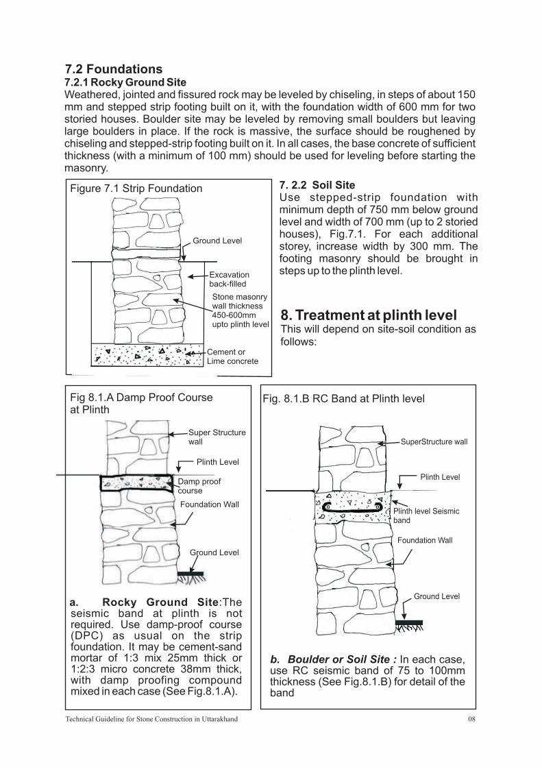
7.2 Foundations 7.2.1 Rocky Ground SiteWeathered, jointed and fissured rock may be leveled by chiseling, in steps of about 150 mm and stepped strip footing built on it, with the foundation width of 600 mm for two storied houses. Boulder site may be leveled by removing small boulders but leaving large boulders in place. If the rock is massive, the surface should be roughened by chiseling and stepped-strip footing built on it. In all cases, the base concrete of sufficient thickness (with a minimum of 100 mm) should be used for leveling before starting the masonry.
7. 2.2 Soil Site Use stepped-strip foundation with minimum depth of 750 mm below ground level and width of 700 mm (up to 2 storied houses), Fig.7.1. For each additional storey, increase width by 300 mm. The footing masonry should be brought in steps up to the plinth level.
Figure 7.1 Strip Foundation
8. Treatment at plinth levelThis will depend on site-soil condition as follows:
a. Rocky Ground Site:The seismic band at plinth is not required. Use damp-proof course (DPC) as usual on the strip foundation. It may be cement-sand mortar of 1:3 mix 25mm thick or 1:2:3 micro concrete 38mm thick, with damp proofing compound mixed in each case (See Fig.8.1.A).
Fig 8.1.A Damp Proof Course at Plinth
b. Boulder or Soil Site : In each case, use RC seismic band of 75 to 100mm thickness (See Fig.8.1.B) for detail of the band
Fig. 8.1.B RC Band at Plinth level
Ground Level
Excavationfilledback-
Cement orLime concrete
Stone masonrywall thickness450-600mmupto plinth level
Plinth Level
Plinth level Seismicband
Foundation Wall
Ground Level
SuperStructure wall
Technical Guideline for Stone Construction in Uttarakhand 08

Through-Stones
BreakingVerticalJoints
Figure 9.1 Interlocking of Wythes
9. Stone Masonry Walls Using Cement MortarStone masonry using cement mortar and other details as set out in the following paragraphs can be used for all building categories in the area.
9.1 Construction Controls
9.1.1 Mortars Superstructure Masonry
Category D – Cement-Sand 1:6
Category E – Cement-Sand 1:4
Having Crushing strength minimum of 35 kg/cm2Foundation masonry up to plinth – Cement-Sand 1:6 in all categories Alternatively instead of cement-sand 1:6 and 1:4 mortars, cement-lime-sand mortar of 1:2:9 and 1:1:6 respectively or Cement-Soil-Sand 1:2:6 may be used.
9.1.2 The wall thickness 't' to be no less than 380 mm and no more than 450mm. The thickness of 380mm will give good insulation in the cold weather.
9.1.3 The inner and outer wythes are to be interlocked with each other through proper stone placement (Figure 9.1).
9.1.4 The masonry should preferably be brought to courses at lifts not greater than 600mm.
Technical Guideline for Stone Construction in Uttarakhand 09

Figure 9.2.B – Vertical Section
t
THROUGHSTONE(TYP.)
900
600
OFLO R LEVEL
Figure 9.2.A – RR Wall - Plan View
T=380
THROUGHSTONE(TYP.) 1
020
21 00 12 00
9.1.5 'Through-Stones' of length equal to the wall thickness should be used in every 600mm lift at horizontal spacing no greater than 1.2 m apart horizontally (Figure 9.2 A &B) If stones of such length are not available, then in place of one full length stone, the stones in pairs of about ¾ of the wall thickness may be used side by side so as to provide an overlap between them.
Technical Guideline for Stone Construction in Uttarakhand 10

EQUL O
AT
WALL THIC
NESK
S
150
51
0
9.1.6 In place of 'Through-Stones' , as the 'bonding elements' there are a number of options. These could be listed as under - The steel bars 8 to 10 mm dia. bent in to 'S'-shape or as links with hooks at both ends and encased in cement mortar may be used with a cover of 25mm from each face of the wall. Alternatively, pre-cast concrete elements of 50x50mm cross-section and reinforced with a 8mm dia. rod placed centrally may be used or solid concrete blocks of 150x150mm cross-section with length equal to the wall thickness may also be used in place of 'Through Stones' (Figure 9.3 A, B, C). Yet another alternative consists of pieces of Galvanized welded wire mesh that could be placed at intervals on top of each course of random rubble masonry.
Figure 9.3.A – Pre-cast Concrete Through-Stone
Figure 9.3.B – Pre-cast RC Through-Stone
LO
EQUA
T
A T
N
WLL
HICK
ESS
D
8MM DIA
. HSD R
O
50
50
Figure 9.3.C Cast In-situ Through Stone
Technical Guideline for Stone Construction in Uttarakhand 11
M2
0 C
ON
CR
ET
EW
ITH
8 H
SD
RO
D

GAL ANIZED
V
I
S
WRE ME
H
IP ECES
900 mm
wt
tw
9
00
mm
90
0
mmtw
090
mm
CORNERSTONES
Figure 9.4. A “L” Corner Masonry 9.1.7 Stones of 600-700mm length s h o u l d b e used at “L” and “ T ” w a l l j u n c t i o n s . Alternatively use 150x150 solid concrete block bonding elements 500-600mm long to connect the perpendicular w a l l s effectively as w e l l a s t o b r e a k t h e joints (Figure 9.4 A).
9.1.8 Corner stiffeners at sill level can be provided with pieces of galvanized welded mesh having width equal to that of the wall plus 900mm that could be placed in “L” and “T” formation at the wall junction (Figure 9.4 B).
Figure 9.4.B Steel bars stiffeners at “L” corners and T-junctions of walls.
Technical Guideline for Stone Construction in Uttarakhand 12

Other option is to use steel reinforcement at corners and T-junctions of walls. Such bars may be in a form of U stirrups or in the configuration as shown in the Figure 9.4.C. The stirrups must be of 8mm dia. laid in 1:3 cement-sand mortar with a minimum cover of 10mm on all sides to minimize corrosion.
Figure 9.4.C Galvanized Wire mesh stiffeners at “L” corner and T junction of walls.
RAINFORCEMENT
tw
450
mm
5
40
mm
tw
450
mm
54 0 mm
tw
Technical Guideline for Stone Construction in Uttarakhand 13

ATTIC
STOREY 2
STOREY 1
9.2 Control of No. of Storeys, Storey Height and Wall Length.
9.2.1 Height of the coursed-rubble masonry walls in cement mortar should be restricted as follows,
Figure 9.5.A – Height restrictions for pitched roof building
Figure 9.5.B – Height restrictions for flat roof building
· Category D – With all the seismic features but without the corners and 'T'
junction stiffeners at Sill level…
For Flat Roof - 2 storeys
For Pitched Roof - 2 storeys plus attic
With 'L' corner and 'T' junction stiffeners at Sill level …
For Flat Roof - 4 storeys
For Pitched Roof – 3 storey plus attic
· Category E – With all the seismic features including the corners and 'T'
junction stiffeners at Sill level…
Flat Roof – 3 storeys and
Pitched Roof – 2 storey plus attic
· Storey height – No greater than 3.2m (Figures 9.5 A & B)
3.2
MM
ax
3.2
MM
ax
STOREY 2
STOREY 1
3.2
MM
ax
3.2
MM
ax
Technical Guideline for Stone Construction in Uttarakhand 14

H/6
H
t w
t w
t w
9.2.2 Length of coursed – rubble masonry walls in cement mortar to be restricted as follows
Figure 9.6.A – Rules for Max. Wall Length
Figure 9.6.B – Buttress dimensions·I f l e n g t h o f w a l l
between two conse-
cutive cross walls is >
5.0m but ≤ 7.0m then
install one buttress at
midpoint (Figure 9.6.A).
·If > 7 m then install
buttresses to the wall
between the cross
walls at intermediate
points with spacing no
greater than 5.0 m
(Figure 9.6.A).
·Buttress size – The
thickness to be maintai-
ned uniform from bottom to top; width at top to be equal to the thickness 't' of main th
wall, and width at the base to be equal to 1/6 of wall height (Figure 9.6.B).
m
5
7
FORL>
m
BUTTRESS SPACIN
GI
E
RS
T
PROVD
BUTT
ES A
DI
L 7
MIPO
NT FOR 5<
m
UT
S
BTRES
L
Technical Guideline for Stone Construction in Uttarakhand 15

A BC
L
(A+B+ ) L .5 C / 0
E 0.45mD 0.56m
ED
A B C
AB
D
C
E
L
(A+B+ )/L .4 C 0 2
E 0.45mD 0.56m
9.3 Control of Door Window Openings in Bearing Walls
9.3.1 Opening in any storey shall preferably have their top at the same level so
that a continuous band could be provided over them in all the walls. The
lintel forms a part of the band while passing over the openings.
9.3.2 The use of arch to span over an opening is a source of weakness and it
better be avoided. Or else, steel tie should be provided across at the base
of the arch.
9.3.3 Door and window openings in walls reduce the shear resisting capacity of
the wall. Hence, to ensure adequate shear resisting capacity, the
openings must be controlled. The openings size and position shall be as
per guidelines below.
a. Ratio of total length of openings in a wall to length of the wall in a room
should not exceed…
1-storeyed – 0.5
2-storeyed – 0.42 (Figure 9.7 & 9.8)
3 or 4 stored – 0.33
This is not dependent upon the type of roof, i.e. whether flat or pitched.
b. Distance of opening measured from inside corner – Shall be no less than
or equal to 450mm.
c. Pier width between consecutive openings – No less than or equal to 560
mm.
Figure 9.7 – Opening rules for single storey building
Figure 9.8 - Opening rules for double storey building
Technical Guideline for Stone Construction in Uttarakhand 16

9.3.4 Where openings do not comply with the guidelines above, they should be strengthened by providing reinforced concrete lining as shown in Figure 9.22 with 2 HSD bars of 10mm dia.
9.4 Required Earthquake Safety Provisions: For Seismic Zones V and IV (MSK
Intensity IX or higher, and VIII respectively) following safety provisions are
specified.
9.4.1 Overall Seismic features arrangements: The principal strengthening
arrangement of seismic reinforcing of masonry buildings consists of horizontal
seismic bands of reinforcements at critical levels, vertical bars at corners and
junction of walls, and encasement of openings
Figure 9.9 A - Band locations in pitched roof building
Figure 9.9 B - Band locations in flat roof building
Technical Guideline for Stone Construction in Uttarakhand 17

x R D
50 BA IA.
m IA.
6mD
M BAR
.S.
0 15 m
0 15 m
9.5 Seismic Bands : Figures 9.9 A & B show the horizontal seismic bands of reinforcements at critical levels for buildings with flat roof and for buildings with sloping roof.
· Seismic Bands shall be provided on all internal and external walls, and shall be uninterrupted at various levels as described below.
· Plinth Band: It is provided at just below the Plinth level on top of masonry foundation wall that is resting on Strip Footing. It is strongly recommended where soils are soft or uneven as frequently happens in hilly tracts. This band serves as damp proof course as well.
· Sill Band: It is provided at just below the window sill. It is needed in all buildings in Category E, but is optional in Category D buildings.
· Lintle Band: It is provided at just above the Lintle level of doors and windows. If the gap between the lintel level and eave or floor level is 600mm (2') or less than this band can be avoided. In such a case the lintel is to be connected to the Eave or Floor level band immediately above it by extending the reinforcement of the lintel to the band (Figure 9.11).
Figure 9.10- RC Band reinforcement ·Eave Band: It is provided
a t j u s t b e l o w t h e Eave/Roof level in case of roof other than RC or RB slab, or if the slab does not cover the support walls fully
·Floor Band: It is provided at just below the Floor l e v e l i n c a s e o f intermediate floor other than RC or RB slab, or if the slab does not cover the support walls fully
·Gable Band: It is provided at Gable level along the sloping top of masonry Gable wall just below the pur l ins . I t mus t be integrally connected to the Eave Band. The details of the band are given below.
·The band width should fully cover the thickness of the wall, and its depth shall be no less than 75mm.
1/2·The band should be made of RC of the grade not leaner than M20 (1:1 :3). ·Requirement of reinforcing bars in RC bands are given in the Table below. ·All longitudinal bars may be welded or suitably lapped for continuity.·The bars must be held in position by 6mm dia. bar cross-links, installed at 150mm
apart as shown in Figure 9.10. Alternatively, 8mm dia. bar cross-links may be used at 300mm apart.
EAVE/ROOF BANDREINFORCEMENT
LINTELREINFORCEMENT
Figure 9.11 - Connection between reinforcement of lintel and lintel band
Technical Guideline for Stone Construction in Uttarakhand 18

Figure 9.13 – “L” corner band reinforcement arrangement
VERTICALREINFORCEMENT
PLINTH, LINTEL &EAVE BAND
NO LAP JOINTNEAR CORNER
Length of wall in room (m) Reinforcing bars by Building Categories. Category D Category E
No. Dia. (mm) No. Dia. (mm) Less than or equal to 5m 2 8 2 10 More than 5m and less than 6m 2 10 2 12 More than 6m and less than 7m 2 12 4 10
All bars must be High strength Deformed (HSD) bars. But 6mm cross-links will be MS.R e f . : “ E a r t h q u a k e r e s i s t a n t reconstruction and new construction of masonry buildings in Jammu and Kashmir State.” Published by National Disaster management division, ministry of Home Affairs, Government of India, 2005
·In case of sloping roofs, triangular gable masonry walls must be enclosed within eave level band and a band at the top of the gable wall. The Gable Band must be integrally connected to Eave Band (Figure 9.12).
·For full integrity of walls at corners and junctions of walls and effective horizontal bending resistance of bands, continuity of reinforcement is essential. The details as shown in the Figures 9.13 & 9.14 are recommended.
Figure 9.12 Eave band to Gable band reinforcement connection
Technical Guideline for Stone Construction in Uttarakhand 19
GABLE BANDREINFORCEMENT
VERTICALBAR BENT
AT TOP
EAVE BANDREINFOR-CEMENT