Embed Size (px)
Citation preview
2007. M82
Page 1 of 5
Coimisiún na Scrúduithe Stáit State Examinations Commission
Leaving Certificate Examination 2007 Technical Drawing Paper II(A) – Ordinary Level (Engineering Applications)
(200 Marks) Friday 15 June Afternoon, 2.00 - 5.00 Instructions (a) Ensure that you have received examination paper M82(L) which accompanies this paper. (b) Answer question 1 and two other questions. (c) Drawings and sketches should be in pencil unless otherwise stated. (d) Where dimensions are omitted they may be estimated. (e) Credit will be given for neat orderly presentation of work. (f) Work on one side of the paper only. (g) Your Examination Number should be written on each drawing sheet used. Note: The following drawings are shown on examination paper M.82(L) which accompanies
this paper: Fig. 1, Fig. 5(a), Fig. 5(b), and Fig. 5(c).

Page 2 of 5
1. Details of a Roller Support Bracket are shown in Fig.1 with a parts list tabulated below.
(a) Assemble the parts and draw, full size, the following views:
(i) a sectional elevation on plane A-A; (ii) a plan projected from (i).
(b) Insert the following on your drawing:
(i) Title:- ROLLER SUPPORT BRACKET; (ii) ISO projection symbol; (iii) Four principal dimensions. (100 marks)
2. Fig.2 shows the elevation and end elevation of a cylindrical pipe which is connected to a triangular duct. A pictorial view is also shown. The pictorial view shows material thickness which may be ignored for the purposes of your drawing.
(a) Draw the given elevation and end elevation.
(b) Draw a surface development of the cylindrical pipe with C-C as the seam line.
(50 marks)
Fig. 2
PART NAME REQUIRED1 Base Plate 12 Bracket 23 Roller 14 Bush 25 Shaft 16 Set Screw 2

Page 3 of 5
3. (a) A radial plate cam has a minimum radius of 42mm and a camshaft diameter of 20mm. The cam rotates in a clockwise direction and imparts the following motion to an inline knife-edge follower:
0° to 30° Dwell;
30° to 210° Rise 54mm with uniform acceleration and retardation;
210° to 270° Fall 14mm with uniform velocity;
270° to 360° Fall 40mm with simple harmonic motion.
Draw the profile of the cam.
Include the displacement diagram as part of the solution.
(b) Fig. 3 shows a link mechanism. Crank OA rotates in an anti-clockwise direction about the fixed point O. A and B are pin joints. Crank BC pivots about the fixed point C.
(i) Using a line diagram to represent the mechanism, plot the locus of point P for one
revolution of the crank OA.
(ii) Draw the profile of a simple machine guard about the mechanism with a minimum clearance of 15mm.
(50 marks)
OA = 40 AP = 150 AB = 100 BC = 100
Fig. 3
Page 4 of 5
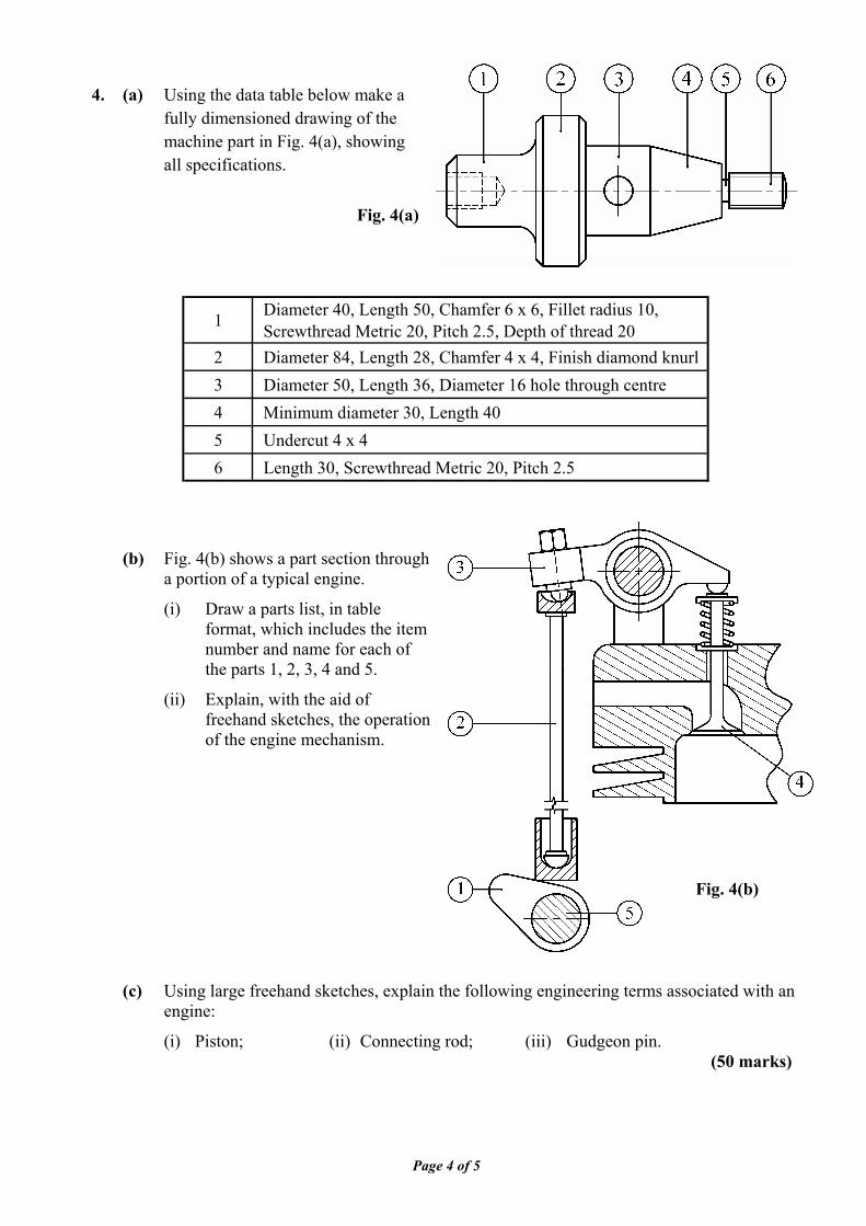
4. (a) Using the data table below make a fully dimensioned drawing of the machine part in Fig. 4(a), showing all specifications.
(b) Fig. 4(b) shows a part section through a portion of a typical engine.
(i) Draw a parts list, in table format, which includes the item number and name for each of the parts 1, 2, 3, 4 and 5.
(ii) Explain, with the aid of freehand sketches, the operation of the engine mechanism.
(c) Using large freehand sketches, explain the following engineering terms associated with an engine:
(i) Piston; (ii) Connecting rod; (iii) Gudgeon pin. (50 marks)
Fig. 4(a)
1 Diameter 40, Length 50, Chamfer 6 x 6, Fillet radius 10,Screwthread Metric 20, Pitch 2.5, Depth of thread 20
2 Diameter 84, Length 28, Chamfer 4 x 4, Finish diamond knurl3 Diameter 50, Length 36, Diameter 16 hole through centre4 Minimum diameter 30, Length 405 Undercut 4 x 46 Length 30, Screwthread Metric 20, Pitch 2.5
Fig. 4(b)

Page 5 of 5
5. Answer SECTION A or SECTION B but not both.
SECTION A
(a) Fig.5(a) shows the elevation and end elevation of a machine casting. Draw an isometric view of the casting with the portion in front of the section plane A-A removed.
Point P is to be the lowest point on the drawing. (b) Using large freehand sketches illustrate the following:
(i) Splined shaft; (ii) Keyway; (iii) Stud.
(50 marks)
OR
SECTION B
(a) List six CAD commands necessary to produce the drawing in Fig.5(b).
(b) By means of sketches and a short note, explain the purpose of the following commands:
(i) Mirror;
(ii) Break;
(iii) Extend.
(c) Using a large freehand sketch, draw the object shown in Fig. 5(c) as a wireframe representation.
(d) Draw, full size, the object that would be displayed on a CAD system when the following commands are executed:
(All points (X,Y) are specified using absolute co-ordinates. The origin (0,0) is located at the lower left corner of the display)
• A rectangle is drawn with its lower left corner at (30,30) and its upper right corner at (190,65)
• The upper corners of the rectangle are chamfered 15 x 15 • A line joins the lower ends of the chamfer lines • A line AB is drawn using the following co-ordinates:
A (75,65) B (75,115) • The line AB is offset 70mm to the right. This new line is indexed CD (point C is on top) • A circular arc is drawn to pass through points B, C and point E (110,215) • A 30mm diameter circle is drawn concentric with the arc • A 16mm diameter circle is drawn with its centre at point (110,195) • The circle is the subject of a circular (polar) array consisting of a total of 5 items.
The centre of the array is located at the centre of the three point arc • A rectangle is drawn with its lower left corner at (85,78) and its upper right corner
at (135,102)
(50 marks)
2007. M82(L)
Page 1 of 3 / Lch 1 de 3
Coimisiún na Scrúduithe Stáit State Examinations Commission
Scrúdú Ardteistiméireachta 2007
Leaving Certificate Examination 2007
Líníocht Theicniúil
Technical Drawing Páipéar II(A) – Gnáthleibhéal
Paper II(A) – Ordinary Level
(Feidhmiúcháin Innealtóireachta)
(Engineering Applications)
Dé hAoine 15 Meitheamh, Tráthnóna, 2.00 - 5.00
Friday 15 June, Afternoon, 2.00 - 5.00 NÓTA: Deimhnigh go bhfuair tú scrúdpháipéar M82T, a ghabhann leis an bpáipéar seo.
NOTE: Ensure that you have received examination paper M82 which accompanies this paper.
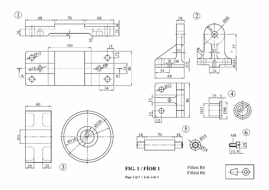
FIG. 1 / FÍOR 1 Page 2 of 3 / Lch. 2 de 3
Fillets R6 Filléid R6

Page 3 of 3 / Lch. 3 de 3
Fig. 5(a) Fíor 5(a)
Fig. 5(b) Fíor 5(b) Fig. 5(c) Fíor 5(c)