Embed Size (px)
Citation preview

Technical Committee on
Hanging and Bracing Systems
MEMORANDUM
DATE: June 26, 2013 TO: Principal and Alternate Members of the Technical Committee on Hanging and
Bracing Systems FROM: Matt Klaus, Principal Fire Protection Engineer/NFPA Staff Liaison SUBJECT: AUT-HBS AGENDA PACKAGE – A2015 Pre-First Draft Meeting ________________________________________________________________________ Enclosed is the agenda for the Pre-First Draft meeting for NFPA 13, Standard for the Installation
of Sprinkler Systems. NFPA 13 has entered the Annual 2015 revision cycle and will produce a
2016 Edition. It is imperative that you review the attached public input in advance, with your
ideas and substantiations for your views. If you have alternate suggestions for text changes,
please come prepared with the words and respective substantiation.
For administrative questions, please feel free to contact Elena Carroll at (617) 984-7952.
For technical questions, please feel free to contact Matt Klaus at (617) 984-7448. You can
also reach either of us via e-mail at [email protected] or [email protected]. We look forward
to meeting everyone in St, Louis, MO at the St. Louis Union Station - a DoubleTree by Hilton
Hotel

Table of Contents
Part 1 - Meeting Agenda
Part 2 - Committee Address List
Part 3 – New Process Worksheets
Part 4 – A2012 ROC Meeting Minutes
Part 5 - A2015 Key Dates
Part 6- HBS Public Input

Technical Committee on Hanging and Bracing Systems
Pre-First Draft Meeting
July 10-11, 2013 St. Louis Union Station - a DoubleTree by Hilton Hotel
1820 Market St. One Union Station St Louis, Missouri, 63103
AGENDA
Wednesday, July 10, 2013
1. Call to Order – 8:00 AM 2. Introductions of Members and Staff 3. Review and Approval of A2012 ROC Meeting Minutes 4. Review of A2015 Revision Cycle and Meeting Schedule 5. Review of Distributed Material and Workload
a. Overview of Public Input b. Overview of Potential Committee First Revisions
6. Establish Task Groups 7. Recess for Task Group Meetings (TBD) 8. Adjourn 12:00 PM 9. Lunch 12:00 PM – 1:00 PM 10. New Process Training and Mock Meeting 1:00 PM – 4:00 PM
Thursday, July 11, 2013
11. Reconvene for Task Group Meetings – 8:00AM 12. Task Group Reports - 1:00 PM 13. Adjourn (TBD)

PART 2 –
COMMITTEE ADDRESS LIST

Address List No PhoneHanging and Bracing of Water-Based Fire Protection Systems AUT-HBS
Automatic Sprinkler Systems
Matthew J. Klaus06/19/2013
AUT-HBS
James B. Biggins
ChairGlobal Risk Consultants Corporation15732 West Barr RoadManhattan, IL 60442-9012
SE 1/16/1998AUT-HBS
Steve Berry
PrincipalRaleigh Fire Department310 West Martin StreetRaleigh, NC 27602
E 10/29/2012
AUT-HBS
Robert G. Caputo
PrincipalFire & Life Safety AmericaConsolidated Fireprotection, Inc.657 Cantara LaneVista, CA 92081
SE 03/05/2012AUT-HBS
Samuel S. Dannaway
PrincipalS. S. Dannaway Associates, Inc.720 Iwilei Road, Suite 412Honolulu, HI 96817-5316
SE 4/17/1998
AUT-HBS
Christopher I. Deneff
PrincipalFM Global270 Central AvenuePO Box 7500Johnston, RI 02919
I 9/30/2004AUT-HBS
Daniel C. Duggan
PrincipalFire Sprinkler Design1318 Colony Way CourtChesterfield, MO 63017Alternate: Daniei J. Duggan, Jr.
M 10/23/2003
AUT-HBS
Thomas J. Forsythe
PrincipalHughes Associates, Inc.2551 San Ramon Valley Blvd., Suite 209San Ramon, CA 94583
SE 1/16/1998AUT-HBS
John D. Gillengerten
PrincipalConsulting Structural Engineer5155 Holly DriveShingle Springs, CA 95682Building Seismic Safety Council/Code Resource SupportCommittee
U 7/14/2004
AUT-HBS
Jeffrey E. Harper
PrincipalThe RJA Group, Inc.Rolf Jensen & Associates, Inc.600 West Fulton Street, 5th FloorChicago, IL 60661-1241Alternate: Matthew W. Donahue
SE 11/2/2006AUT-HBS
David J. Jeltes
PrincipalERICO International Corporation31700 Solon RoadSolon, OH 44139Alternate: Scott E. Anderson
M 8/9/2011
AUT-HBS
Kraig Kirschner
PrincipalAFCON9600 Klingerman StreetPO Box 3365El Monte, CA 91733
M 10/10/1997AUT-HBS
Alan R. Laguna
PrincipalMerit Sprinkler Company, Inc.930 Kenner AvenuePO Box 1447Kenner, LA 70062-1447
IM 10/3/2002
AUT-HBS
George E. Laverick
PrincipalUL LLC333 Pfingsten RoadNorthbrook, IL 60062-2096Alternate: Emil W. Misichko
RT 4/15/2004AUT-HBS
Philip D. LeGrone
PrincipalRisk Management Solutions, Inc.4247 Lindawood DriveNashville, TN 37215
SE 7/12/2001
1

Address List No PhoneHanging and Bracing of Water-Based Fire Protection Systems AUT-HBS
Automatic Sprinkler Systems
Matthew J. Klaus06/19/2013
AUT-HBS
Leslie “Chip” L. Lindley, II
PrincipalLindley Fire Protection Company Inc.2220 East Via BurtonAnaheim, CA 92806Alternate: Leslie L. Lindley
IM 8/9/2011AUT-HBS
Norman J. MacDonald, III
PrincipalFlexHead Industries, Inc.56 Lowland StreetHolliston, MA 01746Alternate: Robert E. Bachman
M 7/29/2005
AUT-HBS
Wayne M. Martin
PrincipalWayne Martin & Associates Inc.136 Bardsdale AvenueOxnard, CA 93035
SE 10/10/1997AUT-HBS
David S. Mowrer
PrincipalBabcock & Wilcox Technical Services, LLCY-12 National Security ComplexPO Box 2009, MS-8107Oak Ridge, TN 37831-8107Alternate: J. Scott Mitchell
U 10/10/1997
AUT-HBS
Randy R. Nelson
PrincipalVFS Fire and Security Services1011 East Lacy AvenueAnaheim, CA 92805
IM 10/10/1997AUT-HBS
Marco R. Nieraeth
PrincipalXL Global Asset Protection Services5641 Pepperwood AvenueLakewood, CA 90712Alternate: Todd A. Dillon
I 3/2/2010
AUT-HBS
Janak B. Patel
PrincipalSavannah River Nuclear Solutions3704 Clark CrossingMartinez, GA 30907
U 10/10/1997AUT-HBS
Michael A. Rothmier
PrincipalUA Joint Apprenticeship Committee LU 6699501 Elmhurst Lane, Unit AHighlands Ranch, CO 80129United Assn. of Journeymen & Apprentices of thePlumbing & Pipe Fitting IndustryAlternate: Charles W. Ketner
L 4/17/1998
AUT-HBS
Daniel Sanchez
PrincipalCity of Los AngelesBuilding & Safety201 North Figueroa Street, Suite 400Los Angeles, CA 90012
E 10/29/2012AUT-HBS
Peter T. Schwab
PrincipalWayne Automatic Fire Sprinklers, Inc.222 Capitol CourtOcoee, FL 34761-3033
IM 3/15/2007
AUT-HBS
Zeljko Sucevic
PrincipalVipond Fire Protection6380 Vipond DriveMississauga, ON L6M 3C1 CanadaCanadian Automatic Sprinkler AssociationAlternate: Matthew Osburn
IM 11/2/2006AUT-HBS
James Tauby
PrincipalMason Industries, Inc.350 Rabro DriveHauppauge, NY 11788
M 10/10/1997
2

Address List No PhoneHanging and Bracing of Water-Based Fire Protection Systems AUT-HBS
Automatic Sprinkler Systems
Matthew J. Klaus06/19/2013
AUT-HBS
Glenn E. Thompson
PrincipalLiberty Mutual National Accounts Property2959 Bighorn DriveCorona, CA 92881-8770Property Casualty Insurers Association of America
I 10/27/2005AUT-HBS
Victoria B. Valentine
PrincipalNational Fire Sprinkler Association, Inc.40 Jon Barrett RoadPatterson, NY 12563National Fire Sprinkler AssociationDesign TechnicianAlternate: Jeffrey A. Hewitt
M 4/3/2003
AUT-HBS
George Von Gnatensky
PrincipalTolco1375 Sampson AvenueCorona, CA 92879-1748National Fire Sprinkler AssociationManufacturerAlternate: Joseph Normandeau
M 10/10/1997AUT-HBS
Kenneth W. Wagoner
PrincipalParsley Consulting Engineers350 West 9th Avenue, Suite 206Escondido, CA 92025-5053American Fire Sprinkler AssociationInstaller/MaintainerAlternate: E. Parks Moore
IM 10/4/2007
AUT-HBS
Ronald N. Webb
PrincipalS.A. Comunale Company, Inc.2900 Newpark DriveBarberton, OH 44203National Fire Sprinkler AssociationContractorAlternate: Sheldon Dacus
IM 1/14/2005AUT-HBS
Thomas G. Wellen
PrincipalAmerican Fire Sprinkler Association, Inc.12750 Merit Drive, Suite 350Dallas, TX 75251American Fire Sprinkler AssociationDesign TechnicianAlternate: Ray Lambert
IM 7/28/2006
AUT-HBS
Jack W. Thacker
Voting AlternateAllan Automatic Sprinkler Corp. of So. California3233 Enterprise StreetBrea, CA 92821
IM 10/10/1997AUT-HBS
Scott E. Anderson
AlternateERICO International Corporation34600 Solon RoadSolon, OH 44139Principal: David J. Jeltes
M 10/29/2012
AUT-HBS
Robert E. Bachman
AlternateRobert E. Bachman, Consulting Structural Engineer25152 La Estrada DriveLaguna Niguel, CA 92677FlexHead Industries, Inc.Principal: Norman J. MacDonald, III
M 11/2/2006AUT-HBS
Sheldon Dacus
AlternateSecurity Fire Protection Company4495 Mendenhall RoadMemphis, TN 38141National Fire Sprinkler AssociationDesign TechnicianPrincipal: Ronald N. Webb
IM 10/10/1997
AUT-HBS
Todd A. Dillon
AlternateXL Global Asset Protection Services1620 Winton AvenueLakewood, OH 44107Principal: Marco R. Nieraeth
I 10/23/2003
3

Address List No PhoneHanging and Bracing of Water-Based Fire Protection Systems AUT-HBS
Automatic Sprinkler Systems
Matthew J. Klaus06/19/2013
AUT-HBS
Matthew W. Donahue
AlternateThe RJA Group, Inc.Rolf Jensen & Associates, Inc.2099 South State College BoulevardSuite 360Anaheim, CA 92806Principal: Jeffrey E. Harper
SE 3/4/2008AUT-HBS
Daniei J. Duggan, Jr.
AlternateVibration & Seismic Technologies30025 Alicia Parkway, #113Laguna Niguel, CA 92677Principal: Daniel C. Duggan
M 10/29/2012
AUT-HBS
Jeffrey A. Hewitt
AlternateBi-State Fire Protection Corporation241 Hughes LaneSt. Charles, MO 63301National Fire Sprinkler AssociationDesign TechnicianPrincipal: Victoria B. Valentine
M 10/29/2012AUT-HBS
Charles W. Ketner
AlternateNational Automatic Sprinkler Fitters LU 669Joint Apprenticeship & Training Committee7050 Oakland Mills RoadColumbia, MD 20732United Assn. of Journeymen & Apprentices of thePlumbing & Pipe Fitting IndustryPrincipal: Michael A. Rothmier
L 1/10/2008
AUT-HBS
Ray Lambert
AlternateWestern Fire Protection Inc.13630 Danielson StreetPoway, CA 92064American Fire Sprinkler AssociationDesign TechnicianPrincipal: Thomas G. Wellen
IM 08/09/2012AUT-HBS
Leslie L. Lindley
AlternateLindley Fire Protection Company Inc.2220 East Via BurtonAnaheim, CA 92806Principal: Leslie “Chip” L. Lindley, II
IM 10/29/2012
AUT-HBS
Emil W. Misichko
AlternateUL LLC333 Pfingsten RoadNorthbrook, IL 60062-2096Principal: George E. Laverick
RT 10/10/1997AUT-HBS
J. Scott Mitchell
AlternateB & W Technical Services PantexPO Box 1241Panhandle, TX 79068Principal: David S. Mowrer
U 7/12/2001
AUT-HBS
E. Parks Moore
AlternateS & S Sprinkler Company, LLCPO Box 7453Mobile, AL 36670American Fire Sprinkler AssociationInstaller/MaintainerPrincipal: Kenneth W. Wagoner
IM 03/05/2012AUT-HBS
Joseph Normandeau
AlternateTyco/SimplexGrinnell12728 Shoemaker AvenueSanta Fe Springs, CA 90670National Fire Sprinkler AssociationManufacturerPrincipal: George Von Gnatensky
M 8/9/2011
AUT-HBS
Matthew Osburn
AlternateCanadian Automatic Sprinkler Association335 Renfrew Drive, Suite 302Markham, ON L3R 9S9 CanadaPrincipal: Zeljko Sucevic
IM 08/09/2012AUT-HBS
Matthew J. Klaus
Staff LiaisonNational Fire Protection Association1 Batterymarch ParkQuincy, MA 02169-7471
12/16/2010
4

PART 3 –
NEW PROCESS WORKSHEETS

March 13, 2012
TERMS New Terms Old Terms
Input Stage – Stage where Public Input is sought to develop the First Draft.
Report on Proposals (ROP) Stage
Public Input (PI) – A recommended change submitted for consideration by the Technical Committee. Each Public Input (PI) shall include new, modified or deleted text as appropriate and technical substantiation to support the recommended change.
Download a Public Input Form for documents in Fall 2013 and subsequent cycles
Proposal
First Draft Meeting ROP Meeting
First Revision (FR) – Proposed changes to the text of an NFPA Standard developed by the responsible Committee(s) in the Input Stage. Each First Revision shall contain the new, modified or deleted text as appropriate. A First Revision shall be established through a Meeting Vote and shall only require a simple majority to proceed to ballot. Only First Revisions that pass ballot will show in the First Draft. Each First Revision shall contain a Committee Statement that substantiates the proposed change to the document.
Committee Proposal or Accepted Public Proposal
Committee Input (CI) – A CI can be established during the First Draft Technical Committee meeting (without balloting) in order to highlight the concept to obtain public comment; often used for newer ideas, topics that aren’t fully fleshed out or controversial topics. A Committee Input (CI) can also be a First Revision (FR) that fails to receive support of the technical committee through letter ballot. Committee Inputs shall maintain the original FR Committee Statement and shall contain a notification to the reviewer documenting that the CI represents a failed FR.
“Trial Balloon” or an Accepted Proposal (or Committee Proposal) that Failed Ballot
Committee Statement (CS) – A Committee Statement is the committee’s response to a Public Input (PI), Public Comment (PC) or the committee’s technical substantiation for a proposed First Revision. A committee statement shall be established through a Meeting Vote and shall only require a simple majority to proceed.
Committee Statement
First Draft Report – The First Draft Report documents the Input Stage; it shall contain the First Draft, Public Input, Committee Input, Committee and Correlating Committee Statements, Correlating Input, Correlating Notes and Ballot Statements.
ROP
First Draft – The draft of the proposed new or revised standard showing in legislative text all First Revisions and First Correlating Revisions that have passed ballot.
ROP Draft
Correlating Committee (CC) Technical Correlating Committee
Correlating Committee Statement – The Correlating Committee’s response to a Public Input (PI), Committee Input (CI), Public Comment (PC) or the Correlating Committee’s technical substantiation for a correlating change to proposed Revision or a correlative CCFR. It shall be established through a Meeting Vote and shall only require a simple majority to proceed.
TCC Note
Correlating Committee First Revision (CCFR) – Correlating Committee First Revisions are proposed revisions to the Technical Committee’s First Revisions that are required to correlate the proposed document. Each CCFR shall contain a Correlating Committee Statement that substantiates the Revision. A CCFR shall be established through a Meeting Vote and shall only require a simple majority to proceed to letter ballot. CCFRs that fail to receive CC support through letter ballot shall not be published as part of the First Draft.
TCC Note
Technical Committee First Draft meeting - Spring 2012 Page 2 of 34 V.2 3/13/2012

Comment Stage Report on Comments (ROC) Stage
Public Comment – Changes submitted by the public during public Comment Stage.
Public Comment
Second Draft Meeting ROC Meeting
Second Revision (SR) – Similar to First Revision, but in the Comment Stage. Proposed changes to the text by the TC that have passed ballot.
Committee Comment or Accepted Public Comment
Committee Comment – A Committee Comment shall be a Second Revision (SR) that fails to receive support of the TC through ballot. Committee Comments shall maintain the original Committee Statement and shall contain a notification to the reviewer documenting that the Committee Comment represents a failed SR.
Committee Comment that failed ballot
Committee Action – An action by a TC to accept or reject a Comment. This occurs only in the Comment Stage and the action itself is not balloted.
Committee Action
Second Draft Report – The Second Draft Report documents the Comment Stage; it shall contain the Second Draft, Public Comments with corresponding Committee Actions and Committee Statements, Committee Comments, Correlating Revisions and Ballot Statements.
ROC
Second Draft – The draft of the proposed new or revised standard showing in legislative text all Second Revisions and Second Correlating Revisions that have passed ballot.
ROC Draft
Technical Committee First Draft meeting - Spring 2012 Page 3 of 34 V.2 3/13/2012
NEW PROCESS ACTIONS AND MOTIONS
New Process Actions and Motions‐ Final‐ 2/13/2012
Possible Action 1: Resolve PIs, (no change to Section)
Action Required Sample MotionsStep One: Committee generates a statement to respond to (resolve)
each PI #
I make a motion (move) to resolve PI#___ with the following committee statement: Approval by a meeting vote (simple majority) and not subject to ballot (Regs 4.3.7.3 & 4.3.7.3.2)
Possible Action 2: Create First Revision ‐ Change to a Section
Action Required Sample MotionsStep One: (1st option)
Committee generates a First Revision I make a motion (move) to revise Section ___ as follows:………… Approval by a meeting vote (simply majority) and final approval through ballot (Regs 4.3.9.2.3)
Step Two: (1st option)
Committee generates a statement substantiating the change.
Approval by a meeting vote (simply majority) (Regs 4.3.7.3)
Step One: (2nd option)
Committee generates a First Revision using one or more PIs as the starting point.
I make a motion to revise Section __ using PI#__ as the basis for change. Approval by a meeting vote (simply majority) and final approval through ballot (Regs 4.3.9.2.3)
Step Two: (2nd option)
If the revision is associated with one or more PIs the committee generates a statement to respond to (resolve) each PI
I make a motion (move) to resolve PIs # through ## with the following statement: Approval by a meeting vote (simply majority) and not subject to ballot (Regs 4.3.7.3 &
4.3.7.3.1)
Possible Action 3: Create Committee Input – (Trial Balloon/Placeholder)
Action Required Sample Motions Step One:
Committee generates a Committee Input (proposed revision) for public consideration and solicitation of Public Comments
I make a motion (move) to create a CI with a proposed revision to X.X.X as follows: Approval by a meeting vote (simply majority) and not subject to ballot (Regs 4.3.8)
Step Two: Committee generates a statement to explain the intent and why it is seeking public consideration and soliciting Public Comments
Approval by a meeting vote (simply majority) (Regs 4.3.7.1)
Technical Committee First Draft meeting - Spring 2012 Page 8 of 34 V.2 3/13/2012

PART 4 –
A2012 ROC MEETING MINUTES

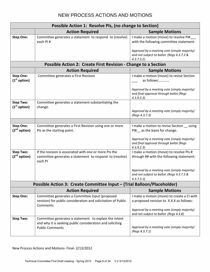
NFPA Technical Committee on Hanging and Bracing of Water-Based
Fire Protection Systems
ROC Meeting
Newport Beach Marriott Newport Beach, California
September 28, 2011
MEETING MINUTES
1. Call to Order. TC Chair Jim Biggins called the meeting to order at 8:00.
2. Self-Introductions of members and guests. Members of the committee
introduced themselves and reviewed the contact information. The meeting attendance list is attached to these minutes.
3. Review of Distributed Meeting Materials. Staff Liaison Matt Klaus provided
an overview of the agenda materials that were sent to the committee and posted on the committee web page.
4. Approval of A12-ROP Draft Meeting Minutes. The minutes of the A12-ROP Meeting were reviewed and approved without modification.
5. Review of Meeting Procedures and Revision Process. Matt Klaus gave a presentation on the overall meeting guidelines and the NFPA Regulations Governing TC operations.
6. Work Load . TC Chair Jim Biggins discussed the logistics for the meeting and
the process to complete the ROC.
7. Public and Committee Comments. The committee then processed the comments. See the ROC for the official actions on the proposals.
8. New Business:
a. The TC plans to form a joint task group with NFPA 15 to address pipe stands consistently within the standards.

b. The TC plans to prepare a letter to the Standard Council to request a clarification of scope in regards to involvement with document outside of NFPA 13.
c. The TC developed a new task group to work on “clearances”. The task
group roster is as follows:
Bob Bachman – “Clearance Task Group” Leader Chip Lindley Victoria Valentine Matt Donahue John Gillengerten Tom Forsythe
d. The TC developed a new task group to work on “yield strength”. The task
group roster is as follows:
John Gillengerten – “Yield Strength Task Group” Leader Bob Bachman Dan Duggan Janak Patel
9. Adjournment. Meeting adjourned at 5:30 pm.


PART 5 –
A2015 KEY DATES

2015 ANNUAL REVISION CYCLE *Public Input Dates may vary according to standards and schedules for Revision Cycles may change. Please check the NFPA Website for the most up‐to‐date information on Public Input Closing Dates and schedules at
www.nfpa.org/document # (i.e. www.nfpa.org/101) and click on the Next Edition tab.
Process Stage
Process Step
Dates for
TC
Dates forTC with CC
Public Input Closing Date* 7/8/2013 7/8/2013
Final Date for TC First Draft Meeting 12/13/2013 9/13/2013
Public Input Posting of First Draft and TC Ballot 1/31/2014 10/25/2013
Stage Final date for Receipt of TC First Draft ballot 7/21/2014 11/15/2013
(First Draft) Final date for Receipt of TC First Draft ballot ‐ recirc 2/28/2014 11/22/2013
Posting of First Draft for CC Meeting 11/29/2013
Final date for CC First Draft Meeting 1/10/2014
Posting of First Draft and CC Ballot 1/31/2014
Final date for Receipt of CC First Draft ballot 2/21/2014
Final date for Receipt of CC First Draft ballot ‐ recirc 2/28/2014
Post First Draft Report for Public Comment 3/7/2014 3/7/2014
Public Comment Closing Date for Paper Submittal* 4/11/2014 4/11/2014
Public Comment Closing Date for Online Submittal (e‐PC)* 5/16/2014 5/16/2014
Final Date to Publish Notice of Consent Documents (Standards that received no Comments)
5/30/2014 5/30/2014
Appeal Closing Date for Consent Standards (Standards that received no Comments)
6/13/2014 6/13/2014
Final date for TC Second Draft Meeting 10/31/2014 7/25/2014
Comment Posting of Second Draft and TC Ballot 12/12/2014 9/5/2014
Stage Final date for Receipt of TC Second Draft ballot 1/2/2015 9/26/2014
(Second Final date for receipt of TC Second Draft ballot ‐ recirc 1/9/2015 10/3/2014
Draft) Posting of Second Draft for CC Meeting 10/10/2014
Final date for CC Second Draft Meeting 11/21/2014
Posting of Second Draft for CC Ballot 12/12/2014
Final date for Receipt of CC Second Draft ballot 1/2/2015
Final date for Receipt of CC Second Draft ballot ‐ recirc 1/9/2015
Post Second Draft Report for NITMAM Review 1/16/2015 1/16/2015
Tech Session Notice of Intent to Make a Motion (NITMAM) Closing Date 3/6/2015 3/6/2015
Preparation Posting of Certified Amending Motions (CAMs) and Consent Standards
5/1/2015 5/1/2015
(& Issuance) Appeal Closing Date for Consent Standards 5/16/2015 5/16/2015
SC Issuance Date for Consent Standards 5/26/2015 5/26/2015
Tech Session Association Meeting for Standards with CAMs 6/22‐25/2016 6/22‐25/2016
Appeals and Appeal Closing Date for Standards with CAMs 7/15/2015 7/15/2015
Issuance SC Issuance Date for Standards with CAMs 8/20/2015 8/20/2015
Approved___ October 18, 2011 _ Revised__March 7, 2013_____________

PART 6 –
PUBLIC INPUT

6/21/13 TerraView™
submittals.nfpa.org/TerraViewWeb/ViewerPage.jsp 47/477
Public Input No. 488-NFPA 13-2013 [ New Section after 3.11.11 ]
3.12 Agro-Industrial Definitions
3.12.1 Agro-Industrial Facility. A facility, or portion thereof, housing operations involving the transformation of raw agriculturalproducts into intermediate or consumable byproducts.
3.12.2 Biomass. Plant or animal-based material of biological origin, excluding material embedded in geological formations or transformed into fossil.
3.12.3 Solid Biofuel. Densified biomass in the form of cubiform, polyhedral, polyhydric or cylindrical units, produced by compressing milled
biomass.
3.12.4 Solid Biomass Feedstock. The basic materials from which biofuel is comprised, manufactured or made.
Statement of Problem and Substantiation for Public Input
The proposed language facilitates the characterization of agro-industrial biomass manufacturing operations by the NFPA 13 user, including the assessment of fire control and the reduction of exposures to and from facilities storing and processing crop-residue and/or animal-based materials of biological origin as "solid biomass feedstock" for industrial-scale, biofuel production. NOTE: The BFICOCS defers to the discretion of the Committee with respect to the most appropriate location for the proposed definitions as they relate to P.I. Nos. 464 and 481 – Section A.5.6.3 and Commodity Classification of solid biomass feedstock (Class III), and P.I. No. 483 – Section A.5.3.2 and Occupancy Classification for agro-industrial facilities (Ordinary Hazard – G2). The Biomass Feedstock Industry Committee on Codes and Standards (BFICOCS), led by Oak Ridge National Laboratory (ORNL), is an initiative of the Department of Energy Biomass Technologies Office (BTO). As part of the BTO integrated biorefinery efforts, the BFICOCS was assembled to conduct analysis of existing fire and building codes and to prepare proposed code changes designed to facilitate the development of the commercial-scale biomass industry while maintaining a focus on safety. The committee is made up of managers, engineers and code officials from industry, government laboratories, consulting firms, and the American Society of Agricultural and Biological Engineers (ASABE). Fire codes related to storage, handling, and pre-processing of biomass are based on industries that operate in a significantly different manner than the growing biomass-based energy industry. Applying current research on biomass properties and knowledge of conventional and emerging storage, handling, and pre-processing technologies, the BFICOCS has submitted changes to both the NFPA and ICC development processes intent on benefiting both industry and the public.
Submitter Information Verification
Submitter Full Name:Darren Meyers
Organization: IECC LLC
Affilliation: Biomass Feedstock Industry Committee on Codes and Standards
Submittal Date: Fri May 31 09:42:26 EDT 2013
Copyright Assignment
I, Darren Meyers, hereby irrevocably grant and assign to the National Fire Protection Association (NFPA) all and full rights in copyright in this Public Input (including both the Proposed
Change and the Statement of Problem and Substantiation). I understand and intend that I acquire no rights, including rights as a joint author, in any publication of the NFPA in w hich this
Public Input in this or another similar or derivative form is used. I hereby w arrant that I am the author of this Public Input and that I have full pow er and authority to enter into this copyright
assignment.
By checking this box I aff irm that I am Darren Meyers, and I agree to be legally bound by the above Copyright Assignment and the terms and conditions contained therein. I understand
and intend that, by checking this box, I am creating an electronic signature that w ill, upon my submission of this form, have the same legal force and effect as a handw ritten signature
/TerraView/Content/13-2013.ditamap/2/C1370007746211.xml
6/21/13 TerraView™
submittals.nfpa.org/TerraViewWeb/ViewerPage.jsp 193/477
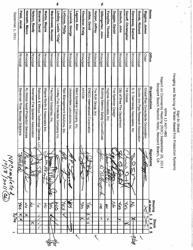
Public Input No. 67-NFPA 13-2013 [ Section No. 9.1.1.3.1.5 ]
Original Hide Markup
9.1.1.3.1.5
Systems that are incompatible with the fire sprinkler systems based on vibration, thermal expansion and contraction, or other factors shall notshare support structures. Systems like fire water drain line, multilayer piping for water supply, CPVC drain lines and condensate drain lines,Chilled Water Insulated pipes can however be installed alongside the fire lines on a single C or U channel fastened with U bolts. The C-channelshall be supported by two threaded rods adequate to handle the cumulative load with all services in operation fastened to the supportingstructure.
Statement of Problem and Substantiation for Public Input
I work for a contracting company and over the years we have come across issues with installation of pipes for different services. I do not know if this item has even been revised or reviewed for that fact that materials used in the construction industry have evolved over the years. Another common issue we face on site is coordination which is paramount to a smooth execution of works. Apart from the integrity of installations having services on a single support (albeit without any major incompatibilities) gives the installation a better aesthetic quality as well. Therefore at this point if time I am merely suggesting this under the assumption that this has not been studied at length or reviewed in the recent past so that if it is indeed possible to run services parallel along with the fire protection on the same support (adequate to support all services) it will greatly ease the work of coordination and also improve the aesthetic quality of installations.
Submitter Information Verification
Submitter Full Name:MOhammed Lodhi
Organization: ETA
Submittal Date: Thu Feb 21 06:50:58 EST 2013
Copyright Assignment
I, MOhammed Lodhi, hereby irrevocably grant and assign to the National Fire Protection Association (NFPA) all and full rights in copyright in this Public Input (including both the Proposed
Change and the Statement of Problem and Substantiation). I understand and intend that I acquire no rights, including rights as a joint author, in any publication of the NFPA in w hich this
Public Input in this or another similar or derivative form is used. I hereby w arrant that I am the author of this Public Input and that I have full pow er and authority to enter into this copyright
assignment.
By checking this box I aff irm that I am MOhammed Lodhi, and I agree to be legally bound by the above Copyright Assignment and the terms and conditions contained therein. I understand
and intend that, by checking this box, I am creating an electronic signature that w ill, upon my submission of this form, have the same legal force and effect as a handw ritten signature
/TerraView/Content/13-2013.ditamap/2/C1361447458265.xml
6/21/13 TerraView™
submittals.nfpa.org/TerraViewWeb/ViewerPage.jsp 194/477
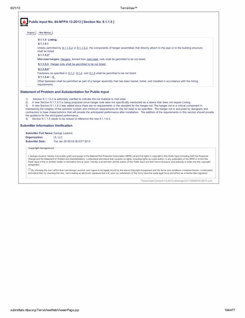
Public Input No. 44-NFPA 13-2013 [ Section No. 9.1.1.5 ]
Original Hide Markup
9.1.1.5 Listing.
9.1.1.5.1
Unless permitted by 9.1.1.5.2 or 9.1.1.5.3, the components of hanger assemblies that directly attach to the pipe or to the building structureshall be listed.
9.1.1.5.2*
Mild steel hangers Hangers formed from mild steel rods shall be permitted to be not listed.
9.1.1.5.3 Hanger rods shall be permitted to be not listed.
9.1.1.5.4 *
Fasteners as specified in 9.1.3, 9.1.4, and 9.1.5 shall be permitted to be not listed.
9.1.1.5.4 5
Other fasteners shall be permitted as part of a hanger assembly that has been tested, listed, and installed in accordance with the listingrequirements.
Statement of Problem and Substantiation for Public Input
1) Section 9.1.1.5.2 is editorially clarified to indicate the rod material is mild steel.2) A new Section 9.1.1.5.3 is being proposed since hanger rods were not specifically mentioned as a device that does not require Listing.3) A new Section 9.1.1.6.3 was added since there are no requirements in the standard for the hanger rod. The hanger rod is a critical component in maintaining the integrity of the sprinkler system and minimum requirements for the rod need to be specified. The hanger rod is assumed by designers and contractors to have characteristics that will provide the anticipated performance after installation. The addition of the requirements in this section should provide the guidance for the anticipated performance. 4) Section 6.1.1.4 needs to be revised to reference the new 9.1.1.6.3.
Submitter Information Verification
Submitter Full Name:George Laverick
Organization: UL LLC
Submittal Date: Tue Jan 29 08:53:38 EST 2013
Copyright Assignment
I, George Laverick, hereby irrevocably grant and assign to the National Fire Protection Association (NFPA) all and full rights in copyright in this Public Input (including both the Proposed
Change and the Statement of Problem and Substantiation). I understand and intend that I acquire no rights, including rights as a joint author, in any publication of the NFPA in w hich this
Public Input in this or another similar or derivative form is used. I hereby w arrant that I am the author of this Public Input and that I have full pow er and authority to enter into this copyright
assignment.
By checking this box I aff irm that I am George Laverick, and I agree to be legally bound by the above Copyright Assignment and the terms and conditions contained therein. I understand
and intend that, by checking this box, I am creating an electronic signature that w ill, upon my submission of this form, have the same legal force and effect as a handw ritten signature
/TerraView/Content/13-2013.ditamap/2/C1359467618474.xml

6/21/13 TerraView™
submittals.nfpa.org/TerraViewWeb/ViewerPage.jsp 195/477
Public Input No. 257-NFPA 13-2013 [ New Section after 9.1.1.5.4 ]
9.1.1.5.5
Wire or cable assemblies used to support pipe hangers from a building structure shall be permitted when tested and listed for the loads indicated in themanufacturer's installation instructions.
A.9.1.1.5.6
Wire or cable assemblies commonly consists of wire or cable and attachment fittings installed at the ends of the wire or cable. The assemblies can beused in place of threaded rod to support pipe hangers and are intended to be attached to structural members or hangers specifically intended for thisapplication that are attached to the structure and where minimum test loads of the complete suspension and hanger assembly meet the requirementsof 9.1.1.2.
9.1.1.5.7
Wire or cable assemblies should be designed to support the weight of the water filled pipe (the weight of the pipe as listed in ANSI Schedule 40 and theweight of the water filled pipe as listed in ASME/ANSI B36. 10/19) plus 250lbs (114kg) at each point of support. The spacing between hangerssupported by wire assemblies should be not exceed the value given for the type of pipe indicated in Table 9.2.2.1 (a) and Table 9.2.2.1 (b).
9.1.1.5.8
Wire or cable should be manufactured to EN standards BSEN10244 which determines the zinc coating level and BSEN12385 which covers theprocessing of the material, the wire rope characteristics (such as tensile strength, diameter and how it is tested, or equivalents
Additional Proposed Changes
File Name Description Approved
Open nfpa13_-_wire_application.docx Original Electronically submitted proposal
Statement of Problem and Substantiation for Public Input
Section 9.1.1.5.5 is a new section that proposes wire/cable assemblies as permitted to hang pipe hangers from a building structure as there is current listing indicated for this type of hanging systemSection 9.1.1.5.6 is added to explain the common wire/cable assemblies. They can be used in place of rod to support hangers from the building structure, as long as they meet the requirements in 9.1.1.2Section 9.1.1.5.7 Builds upon 5.1.1.6 specifically for wire assemblies showing the listing that the wire assemblies should be designed to support. Referenced are ANSI Schedule 40 for Steel Pipe, ASME.ANSI B36. 10/19 and Tables 9.2.2.1 (a) and (b)
Section 9.1.1.5.8 References the EN standards (and any equivalent standards) that wire rope should be manufactured to. These standards included characteristics such as tensile strength, diameter and testing
Submitter Information Verification
Submitter Full Name:DAN DESLER
Organization: GRIPPLE
Submittal Date: Mon May 06 10:21:34 EDT 2013
Copyright Assignment
I, DAN DESLER, hereby irrevocably grant and assign to the National Fire Protection Association (NFPA) all and full rights in copyright in this Public Input (including both the Proposed Change
and the Statement of Problem and Substantiation). I understand and intend that I acquire no rights, including rights as a joint author, in any publication of the NFPA in w hich this Public Input in
this or another similar or derivative form is used. I hereby w arrant that I am the author of this Public Input and that I have full pow er and authority to enter into this copyright assignment.
By checking this box I aff irm that I am DAN DESLER, and I agree to be legally bound by the above Copyright Assignment and the terms and conditions contained therein. I understand and
intend that, by checking this box, I am creating an electronic signature that w ill, upon my submission of this form, have the same legal force and effect as a handw ritten signature
/TerraView/Content/13-2013.ditamap/2/C1367850094105.xml

6/21/13 TerraView™
submittals.nfpa.org/TerraViewWeb/ViewerPage.jsp 196/477
Public Input No. 25-NFPA 13-2013 [ Section No. 9.1.1.5.4 ]
Original Hide Markup
9.1.1.5.4
Other fasteners fastener types or designs not covered under Sections 9.1.3, 9.1.4, and 9.1.5, shall be permitted as part of a hanger assemblythat has been tested, listed, and installed in accordance with the listing requirements.
Additional Proposed Changes
File Name Description Approved
Open 13_Laverick_9-1-1-5-4.docx Cover Sheet
Statement of Problem and Substantiation for Public Input
The proposal clarifies that common fastener requirements cannot be reduced based on testing a hanger assembly. The current requirements consider fastening into materials having unknown or uncontrolled conditions such as a void or knot area of a wood beam and should not be reduced.
Submitter Information Verification
Submitter Full Name:George Laverick
Organization: UL LLC
Submittal Date: Thu Jan 24 10:51:33 EST 2013
Copyright Assignment
I, George Laverick, hereby irrevocably grant and assign to the National Fire Protection Association (NFPA) all and full rights in copyright in this Public Input (including both the Proposed
Change and the Statement of Problem and Substantiation). I understand and intend that I acquire no rights, including rights as a joint author, in any publication of the NFPA in w hich this
Public Input in this or another similar or derivative form is used. I hereby w arrant that I am the author of this Public Input and that I have full pow er and authority to enter into this copyright
assignment.
By checking this box I aff irm that I am George Laverick, and I agree to be legally bound by the above Copyright Assignment and the terms and conditions contained therein. I understand
and intend that, by checking this box, I am creating an electronic signature that w ill, upon my submission of this form, have the same legal force and effect as a handw ritten signature
/TerraView/Content/13-2013.ditamap/2/C1359042693460.xml

6/21/13 TerraView™
submittals.nfpa.org/TerraViewWeb/ViewerPage.jsp 197/477
Public Input No. 45-NFPA 13-2013 [ Section No. 9.1.1.6 ]
Original Hide Markup
9.1.1.6 Component Material.
9.1.1.6.1
Unless permitted by 9.1.1.6.2 or 9.1.1.6.3, hangers and their components shall be ferrous.
9.1.1.6.2
Nonferrous components that have been proven by fire tests to be adequate for the hazard application, that are listed for this purpose, and that arein compliance with the other requirements of this section shall be acceptable.
9.1.1.6.
3
3 Hanger rods shall be fabricated from steel that meets the requirements of ASTM A307, Standard Specification for Carbon Steel Bolts andStuds, 60 000 PSI Tensile Strength, Grade A or B, or the material, strength and fit requirements of other equivalent standards.
9.1.1.6.4
Holes through solid structural members shall be permitted to serve as hangers for the support of system piping provided such holes are permittedby applicable building codes and the spacing and support provisions for hangers of this standard are satisfied.
Statement of Problem and Substantiation for Public Input
1) Section 9.1.1.5.2 is editorially clarified to indicate the rod material is mild steel.2) A new Section 9.1.1.5.3 is being proposed since hanger rods were not specifically mentioned as a device that does not require Listing.3) A new Section 9.1.1.6.3 was added since there are no requirements in the standard for the hanger rod. The hanger rod is a critical component in maintaining the integrity of the sprinkler system and minimum requirements for the rod need to be specified. The hanger rod is assumed by designers and contractors to have characteristics that will provide the anticipated performance after installation. The addition of the requirements in this section should provide the guidance for the anticipated performance. 4) Section 6.1.1.4 needs to be revised to reference the new 9.1.1.6.3.
Submitter Information Verification
Submitter Full Name:George Laverick
Organization: UL LLC
Submittal Date: Tue Jan 29 08:58:01 EST 2013
Copyright Assignment
I, George Laverick, hereby irrevocably grant and assign to the National Fire Protection Association (NFPA) all and full rights in copyright in this Public Input (including both the Proposed
Change and the Statement of Problem and Substantiation). I understand and intend that I acquire no rights, including rights as a joint author, in any publication of the NFPA in w hich this
Public Input in this or another similar or derivative form is used. I hereby w arrant that I am the author of this Public Input and that I have full pow er and authority to enter into this copyright
assignment.
By checking this box I aff irm that I am George Laverick, and I agree to be legally bound by the above Copyright Assignment and the terms and conditions contained therein. I understand
and intend that, by checking this box, I am creating an electronic signature that w ill, upon my submission of this form, have the same legal force and effect as a handw ritten signature
Public Input No. 224-NFPA 13-2013 [ Section No. 9.1.1.7.1 ]
Original Hide Markup
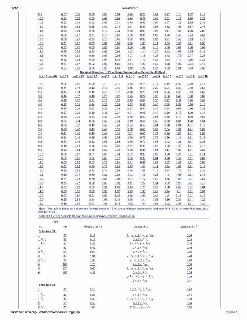
9.1.1.7.1
For trapeze hangers, the minimum size of steel angle or pipe span between purlins or joists shall be such that the section modulus required inTable 9.1.1.7.1(a) does not exceed the available section modulus of the trapeze member from Table 9.1.1.7.1(b).
Table 9.1.1.7.1(a) Section Modulus Required for Trapeze Members (in.3)
bold"Nominal Diameter of Pipe (in.) Being Supported — Schedule 10 Steel
Span (ft) 1 1.25 1.5 2 2.5 3 3.5 4 5 6 8 10
1.5 0.08 0.08 0.09 0.09 0.10 0.11 0.12 0.13 0.15 0.18 0.26 0.34
2.0 0.11 0.11 0.12 0.13 0.14 0.15 0.16 0.17 0.20 0.24 0.34 0.45
2.5 0.14 0.14 0.15 0.16 0.18 0.21 0.23 0.25 0.30 0.36 0.50 0.69
3.0 0.16 0.17 0.18 0.19 0.20 0.22 0.24 0.26 0.31 0.36 0.51 0.67
3.5 0.19 0.20 0.21 0.22 0.24 0.26 0.28 0.30 0.36 0.42 0.60 0.78
4.0 0.22 0.22 0.24 0.25 0.27 0.30 0.32 0.34 0.41 0.48 0.68 0.89
4.5 0.24 0.25 0.27 0.28 0.30 0.33 0.36 0.38 0.46 0.54 0.77 1.01
5.0 0.27 0.28 0.30 0.31 0.34 0.37 0.40 0.43 0.51 0.60 0.85 1.12
5.5 0.30 0.31 0.33 0.34 0.37 0.41 0.44 0.47 0.56 0.66 0.94 1.23
6.0 0.33 0.34 0.35 0.38 0.41 0.44 0.48 0.51 0.61 0.71 1.02 1.34
6.5 0.35 0.36 0.38 0.41 0.44 0.48 0.52 0.56 0.66 0.77 1.11 1.45
7.0 0.38 0.39 0.41 0.44 0.47 0.52 0.56 0.60 0.71 0.83 1.19 1.56
7.5 0.41 0.42 0.44 0.47 0.51 0.55 0.60 0.64 0.76 0.89 1.28 1.68
8.0 0.43 0.45 0.47 0.50 0.54 0.59 0.63 0.68 0.82 0.95 1.36 1.79
8.5 0.46 0.48 0.50 0.53 0.58 0.63 0.67 0.73 0.87 1.01 1.45 1.90
/TerraView/Content/13-2013.ditamap/2/C1359467881644.xml

6/21/13 TerraView™
submittals.nfpa.org/TerraViewWeb/ViewerPage.jsp 198/477
9.0 0.49 0.50 0.53 0.56 0.61 0.66 0.71 0.77 0.92 1.07 1.53 2.01
9.5 0.52 0.53 0.56 0.60 0.64 0.70 0.75 0.81 0.97 1.13 1.62 2.12
10.0 0.54 0.56 0.59 0.63 0.68 0.74 0.79 0.85 1.02 1.19 1.70 2.23
10.5 0.57 0.59 0.62 0.66 0.71 0.78 0.83 0.90 1.07 1.25 1.79 2.35
11.0 0.60 0.62 0.65 0.69 0.74 0.81 0.87 0.94 1.12 1.31 1.87 2.46
11.5 0.63 0.64 0.68 0.72 0.78 0.85 0.91 0.98 1.17 1.37 1.96 2.57
12.0 0.65 0.67 0.71 0.75 0.81 0.89 0.95 1.02 1.22 1.43 2.04 2.68
12.5 0.68 0.70 0.74 0.78 0.85 0.92 0.99 1.07 1.27 1.49 2.13 2.79
13.0 0.71 0.73 0.77 0.81 0.88 0.96 1.03 1.11 1.33 1.55 2.21 2.90
13.5 0.73 0.76 0.80 0.85 0.91 1.00 1.07 1.15 1.38 1.61 2.30 3.02
14.0 0.76 0.78 0.83 0.88 0.95 1.03 1.11 1.20 1.43 1.67 2.38 3.13
14.5 0.79 0.81 0.86 0.91 0.98 1.07 1.15 1.24 1.48 1.73 2.47 3.24
15.0 0.82 0.84 0.89 0.94 1.02 1.11 1.19 1.28 1.53 1.79 2.56 3.35
15.5 0.84 0.87 0.92 0.97 1.05 1.14 1.23 1.32 1.58 1.85 2.64 3.46
16.0 0.87 0.90 0.95 1.00 1.08 1.18 1.27 1.37 1.63 1.91 2.73 3.58
Nominal Diameter of Pipe (in.) Being Supported — Schedule 40 Steel
bold" Span (ft) bold" 1 bold" 1.25 bold" 1.5 bold" 2 bold" 2.5 bold" 3 bold" 3.5 bold" 4 bold" 5 bold" 6 bold" 8 bold" 10
1.5 0.08 0.09 0.09 0.1 0.11 0.12 0.14 0.15 0.18 0.22 0.30 0.41
2.0 0.11 0.11 0.12 0.13 0.15 0.16 0.18 0.20 0.24 0.29 0.40 0.55
2.5 0.14 0.14 0.15 0.16 0.17 0.18 0.20 0.21 0.25 0.30 0.43 0.56
3.0 0.16 0.17 0.18 0.20 0.22 0.25 0.27 0.30 0.36 0.43 0.60 0.82
3.5 0.19 0.20 0.21 0.23 0.26 0.29 0.32 0.35 0.42 0.51 0.70 0.96
4.0 0.22 0.23 0.24 0.26 0.29 0.33 0.36 0.40 0.48 0.58 0.80 1.10
4.5 0.25 0.26 0.27 0.29 0.33 0.37 0.41 0.45 0.54 0.65 0.90 1.23
5.0 0.27 0.29 0.30 0.33 0.37 0.41 0.45 0.49 0.60 0.72 1.00 1.37
5.5 0.30 0.31 0.33 0.36 0.40 0.45 0.50 0.54 0.66 0.79 1.10 1.51
6.0 0.33 0.34 0.36 0.39 0.44 0.49 0.54 0.59 0.72 0.87 1.20 1.64
6.5 0.36 0.37 0.40 0.42 0.48 0.54 0.59 0.64 0.78 0.94 1.31 1.78
7.0 0.38 0.40 0.43 0.46 0.52 0.58 0.63 0.69 0.84 1.01 1.41 1.92
7.5 0.41 0.43 0.46 0.49 0.55 0.62 0.68 0.74 0.90 1.08 1.51 2.06
8.0 0.44 0.46 0.49 0.52 0.59 0.66 0.72 0.79 0.96 1.16 1.61 2.19
8.5 0.47 0.48 0.52 0.56 0.63 0.70 0.77 0.84 1.02 1.23 1.71 2.33
9.0 0.49 0.51 0.55 0.59 0.66 0.74 0.81 0.89 1.08 1.30 1.81 2.47
9.5 0.52 0.54 0.58 0.62 0.70 0.78 0.86 0.94 1.14 1.37 1.91 2.60
10.0 0.55 0.57 0.61 0.65 0.74 0.82 0.90 0.99 1.20 1.45 2.01 2.74
10.5 0.58 0.60 0.64 0.69 0.77 0.86 0.95 1.04 1.26 1.52 2.11 2.88
11.0 0.60 0.63 0.67 0.72 0.81 0.91 0.99 1.09 1.32 1.59 2.21 3.01
11.5 0.63 0.66 0.70 0.75 0.85 0.95 1.04 1.14 1.38 1.66 2.31 3.15
12.0 0.66 0.68 0.73 0.78 0.88 0.99 1.08 1.19 1.44 1.73 2.41 3.29
12.5 0.69 0.71 0.76 0.82 0.92 1.03 1.13 1.24 1.5 1.81 2.51 3.43
13.0 0.71 0.74 0.79 0.85 0.96 1.07 1.17 1.29 1.56 1.88 2.61 3.56
13.5 0.74 0.77 0.82 0.88 0.99 1.11 1.22 1.34 1.62 1.95 2.71 3.70
14.0 0.77 0.80 0.85 0.91 1.03 1.15 1.26 1.39 1.68 2.02 2.81 3.84
14.5 0.80 0.83 0.88 0.95 1.07 1.19 1.31 1.43 1.74 2.1 2.91 3.97
15.0 0.82 0.86 0.91 0.98 1.10 1.24 1.35 1.48 1.8 2.17 3.01 4.11
15.5 0.85 0.88 0.94 1.01 1.14 1.28 1.4 1.53 1.86 2.24 3.11 4.25
16.0 0.88 0.91 0.97 1.05 1.18 1.32 1.44 1.58 1.92 2.31 3.21 4.39
Table 9.1.1.7.1(b) Available Section Modulus of Common Trapeze Hangers (in.3)
Pipe
Modulus (in.3) Angles (in.) Modulus (in.3)in. mm
Schedule 10
1 25 0.12 1 1⁄2 × 1 1⁄2 × 3⁄16 0.10
1 1⁄4 32 0.19 2 × 2 × 1⁄8 0.13
1 1⁄2 40 0.26 2 × 1 1⁄2 × 3⁄16 0.18
2 50 0.42 2 × 2 × 3⁄16 0.19
2 1⁄2 65 0.69 2 × 2 × 1⁄4 0.25
3 80 1.04 2 1⁄2 × 1 1⁄2 × 3⁄16 0.28
3 1⁄2 90 1.38 2 1⁄2 × 2 × 3⁄16 0.29
4 100 1.76 2 × 2 × 5⁄16 0.30
5 125 3.03 2 1⁄2 × 2 1⁄2 × 3⁄16 0.30
6 150 4.35 2 × 2 × 3⁄8 0.35
2 1⁄2 × 2 1⁄2 × 1⁄4 0.39
3 × 2 × 3⁄16 0.41
Schedule 40
1 25 0.13 3 × 2 1⁄2 × 3⁄16 0.43
1 1⁄4 32 0.23 3 × 3 × 3⁄16 0.44
1 1⁄2 40 0.33 2 1⁄2 × 2 1⁄2 × 5⁄16 0.48
2 50 0.56 3 × 2 × 1⁄4 0.54
2 1⁄2 65 1.06 2 1⁄2 × 2 × 3⁄8 0.55
3 80 1.72 2 1⁄2 × 2 1⁄2 × 3⁄8 0.57
3 1⁄2 90 2.39 3 × 3 × 1⁄4 0.58

6/21/13 TerraView™
submittals.nfpa.org/TerraViewWeb/ViewerPage.jsp 199/477
4 100 3.21 3 × 3 × 5⁄16 0.71
5 125 5.45 2 1⁄2 × 2 1⁄2 × 1⁄2 0.72
6 150 8.50 3 1⁄2 × 2 1⁄2 × 1⁄4 0.75
3 × 2 1⁄2 × 3⁄8 0.81
3 × 3 × 3⁄8 0.83
3 1⁄2 × 2 1⁄2 × 5⁄16 0.93
3 × 3 × 7⁄16 0.95
4 × 4 × 1⁄4 1.05
3 × 3 × 1⁄2 1.07
4 × 3 × 5⁄16 1.23
4 × 4 × 5⁄16 1.29
4 × 3 × 3⁄8 1.46
4 ×4 × 3⁄8 1.52
5 × 3 1⁄2 × 5⁄16 1.94
4 × 4 × 1⁄2 1.97
4 × 4 × 5⁄8 2.40
4 × 4 × 3⁄4 2.81
6 × 4 × 3⁄8 3.32
6 × 4 × 1⁄2 4.33
6 × 4 × 3⁄4 6.25
6 × 6 × 1 8.57
For SI units, 1 in. = 25.4 mm; 1 ft = 0.3048 m.
Statement of Problem and Substantiation for Public Input
Table currently does not specify the units of the internal diameter of piping. Adding (in.) will clarify. Note that this is the only change being proposed to this table in this public input. We are just asking to add "(in.)" to the heading above the span in both parts of the table.
Submitter Information Verification
Submitter Full Name:Roland Asp
Organization: National Fire Sprinkler Associ
Submittal Date: Thu Apr 25 09:15:20 EDT 2013
Copyright Assignment
I, Roland Asp, hereby irrevocably grant and assign to the National Fire Protection Association (NFPA) all and full rights in copyright in this Public Input (including both the Proposed Change
and the Statement of Problem and Substantiation). I understand and intend that I acquire no rights, including rights as a joint author, in any publication of the NFPA in w hich this Public Input in
this or another similar or derivative form is used. I hereby w arrant that I am the author of this Public Input and that I have full pow er and authority to enter into this copyright assignment.
By checking this box I aff irm that I am Roland Asp, and I agree to be legally bound by the above Copyright Assignment and the terms and conditions contained therein. I understand and
intend that, by checking this box, I am creating an electronic signature that w ill, upon my submission of this form, have the same legal force and effect as a handw ritten signature
Public Input No. 225-NFPA 13-2013 [ Section No. 9.1.1.7.1 ]
Original Hide Markup
9.1.1.7.1
For trapeze hangers, the minimum size of steel angle or pipe span between purlins or joists shall be such that the section modulus required inTable 9.1.1.7.1(a) does not exceed the available section modulus of the trapeze member from Table 9.1.1.7.1(b) .
Table 9.1.1.7.1(a) Section Modulus Required for Trapeze Members (in.3)
bold"Nominal Diameter of Pipe Being Supported — Schedule 10 Steel
Span (ft) 1 1.25 1.5 2 2.5 3 3.5 4 5 6 8 10
1.5 0.08 0.08 0.09 0.09 0.10 0.11 0.12 0.13 0.15 0.18 0.26 0.34
2.0 0.11 0.11 0.12 0.13 0.14 0.15 0.16 0.17 0.20 0.24 0.34 0.45
2.5 0.14 0.14 0.15 0.16 0.18 0.21 0.23 0.25 0.30 0.36 0.50 0.69
3.0 0.16 0.17 0.18 0.19 0.20 0.22 0.24 0.26 0.31 0.36 0.51 0.67
3.5 0.19 0.20 0.21 0.22 0.24 0.26 0.28 0.30 0.36 0.42 0.60 0.78
4.0 0.22 0.22 0.24 0.25 0.27 0.30 0.32 0.34 0.41 0.48 0.68 0.89
4.5 0.24 0.25 0.27 0.28 0.30 0.33 0.36 0.38 0.46 0.54 0.77 1.01
5.0 0.27 0.28 0.30 0.31 0.34 0.37 0.40 0.43 0.51 0.60 0.85 1.12
5.5 0.30 0.31 0.33 0.34 0.37 0.41 0.44 0.47 0.56 0.66 0.94 1.23
6.0 0.33 0.34 0.35 0.38 0.41 0.44 0.48 0.51 0.61 0.71 1.02 1.34
6.5 0.35 0.36 0.38 0.41 0.44 0.48 0.52 0.56 0.66 0.77 1.11 1.45
7.0 0.38 0.39 0.41 0.44 0.47 0.52 0.56 0.60 0.71 0.83 1.19 1.56
7.5 0.41 0.42 0.44 0.47 0.51 0.55 0.60 0.64 0.76 0.89 1.28 1.68
8.0 0.43 0.45 0.47 0.50 0.54 0.59 0.63 0.68 0.82 0.95 1.36 1.79
8.5 0.46 0.48 0.50 0.53 0.58 0.63 0.67 0.73 0.87 1.01 1.45 1.90
9.0 0.49 0.50 0.53 0.56 0.61 0.66 0.71 0.77 0.92 1.07 1.53 2.01
/TerraView/Content/13-2013.ditamap/2/C1366895720307.xml
6/21/13 TerraView™
submittals.nfpa.org/TerraViewWeb/ViewerPage.jsp 200/477
9.5 0.52 0.53 0.56 0.60 0.64 0.70 0.75 0.81 0.97 1.13 1.62 2.12
10.0 0.54 0.56 0.59 0.63 0.68 0.74 0.79 0.85 1.02 1.19 1.70 2.23
10.5 0.57 0.59 0.62 0.66 0.71 0.78 0.83 0.90 1.07 1.25 1.79 2.35
11.0 0.60 0.62 0.65 0.69 0.74 0.81 0.87 0.94 1.12 1.31 1.87 2.46
11.5 0.63 0.64 0.68 0.72 0.78 0.85 0.91 0.98 1.17 1.37 1.96 2.57
12.0 0.65 0.67 0.71 0.75 0.81 0.89 0.95 1.02 1.22 1.43 2.04 2.68
12.5 0.68 0.70 0.74 0.78 0.85 0.92 0.99 1.07 1.27 1.49 2.13 2.79
13.0 0.71 0.73 0.77 0.81 0.88 0.96 1.03 1.11 1.33 1.55 2.21 2.90
13.5 0.73 0.76 0.80 0.85 0.91 1.00 1.07 1.15 1.38 1.61 2.30 3.02
14.0 0.76 0.78 0.83 0.88 0.95 1.03 1.11 1.20 1.43 1.67 2.38 3.13
14.5 0.79 0.81 0.86 0.91 0.98 1.07 1.15 1.24 1.48 1.73 2.47 3.24
15.0 0.82 0.84 0.89 0.94 1.02 1.11 1.19 1.28 1.53 1.79 2.56 3.35
15.5 0.84 0.87 0.92 0.97 1.05 1.14 1.23 1.32 1.58 1.85 2.64 3.46
16.0 0.87 0.90 0.95 1.00 1.08 1.18 1.27 1.37 1.63 1.91 2.73 3.58
Nominal Diameter of Pipe Being Supported — Schedule 40 Steel
bold" Span (ft) bold" 1 bold" 1.25 bold" 1.5 bold" 2 bold" 2.5 bold" 3 bold" 3.5 bold" 4 bold" 5 bold" 6 bold" 8 bold" 10
1.5 0.08 0.09 0.09 0.1 0.11 0.12 0.14 0.15 0.18 0.22 0.30 0.41
2.0 0.11 0.11 0.12 0.13 0.15 0.16 0.18 0.20 0.24 0.29 0.40 0.55
2.5 0.14 0.14 0.15 0.16 0.17 0.18 0.20 0.21 0.25 0.30 0.43 0.56
3.0 0.16 0.17 0.18 0.20 0.22 0.25 0.27 0.30 0.36 0.43 0.60 0.82
3.5 0.19 0.20 0.21 0.23 0.26 0.29 0.32 0.35 0.42 0.51 0.70 0.96
4.0 0.22 0.23 0.24 0.26 0.29 0.33 0.36 0.40 0.48 0.58 0.80 1.10
4.5 0.25 0.26 0.27 0.29 0.33 0.37 0.41 0.45 0.54 0.65 0.90 1.23
5.0 0.27 0.29 0.30 0.33 0.37 0.41 0.45 0.49 0.60 0.72 1.00 1.37
5.5 0.30 0.31 0.33 0.36 0.40 0.45 0.50 0.54 0.66 0.79 1.10 1.51
6.0 0.33 0.34 0.36 0.39 0.44 0.49 0.54 0.59 0.72 0.87 1.20 1.64
6.5 0.36 0.37 0.40 0.42 0.48 0.54 0.59 0.64 0.78 0.94 1.31 1.78
7.0 0.38 0.40 0.43 0.46 0.52 0.58 0.63 0.69 0.84 1.01 1.41 1.92
7.5 0.41 0.43 0.46 0.49 0.55 0.62 0.68 0.74 0.90 1.08 1.51 2.06
8.0 0.44 0.46 0.49 0.52 0.59 0.66 0.72 0.79 0.96 1.16 1.61 2.19
8.5 0.47 0.48 0.52 0.56 0.63 0.70 0.77 0.84 1.02 1.23 1.71 2.33
9.0 0.49 0.51 0.55 0.59 0.66 0.74 0.81 0.89 1.08 1.30 1.81 2.47
9.5 0.52 0.54 0.58 0.62 0.70 0.78 0.86 0.94 1.14 1.37 1.91 2.60
10.0 0.55 0.57 0.61 0.65 0.74 0.82 0.90 0.99 1.20 1.45 2.01 2.74
10.5 0.58 0.60 0.64 0.69 0.77 0.86 0.95 1.04 1.26 1.52 2.11 2.88
11.0 0.60 0.63 0.67 0.72 0.81 0.91 0.99 1.09 1.32 1.59 2.21 3.01
11.5 0.63 0.66 0.70 0.75 0.85 0.95 1.04 1.14 1.38 1.66 2.31 3.15
12.0 0.66 0.68 0.73 0.78 0.88 0.99 1.08 1.19 1.44 1.73 2.41 3.29
12.5 0.69 0.71 0.76 0.82 0.92 1.03 1.13 1.24 1.5 1.81 2.51 3.43
13.0 0.71 0.74 0.79 0.85 0.96 1.07 1.17 1.29 1.56 1.88 2.61 3.56
13.5 0.74 0.77 0.82 0.88 0.99 1.11 1.22 1.34 1.62 1.95 2.71 3.70
14.0 0.77 0.80 0.85 0.91 1.03 1.15 1.26 1.39 1.68 2.02 2.81 3.84
14.5 0.80 0.83 0.88 0.95 1.07 1.19 1.31 1.43 1.74 2.1 2.91 3.97
15.0 0.82 0.86 0.91 0.98 1.10 1.24 1.35 1.48 1.8 2.17 3.01 4.11
15.5 0.85 0.88 0.94 1.01 1.14 1.28 1.4 1.53 1.86 2.24 3.11 4.25
16.0 0.88 0.91 0.97 1.05 1.18 1.32 1.44 1.58 1.92 2.31 3.21 4.39
Note: The table is based on a maximum bending stress of 15 ksi and a midspan concentrated load from 15 ft (4.6 m) of water-filled pipe, plus250 lb (114 kg).
Table 9.1.1.7.1(b) Available Section Modulus of Common Trapeze Hangers (in.3)
Pipe
Modulus (in. 3 ) Angles (in.) Modulus (in. 3 )in. mm
Schedule 10
1 25 0.12 1 1 ⁄ 2 × 1 1 ⁄ 2 × 3 ⁄ 16 0.10
1 1 ⁄ 4 32 0.19 2 × 2 × 1 ⁄ 8 0.13
1 1 ⁄ 2 40 0.26 2 × 1 1 ⁄ 2 × 3 ⁄ 16 0.18
2 50 0.42 2 × 2 × 3 ⁄ 16 0.19
2 1 ⁄ 2 65 0.69 2 × 2 × 1 ⁄ 4 0.25
3 80 1.04 2 1 ⁄ 2 × 1 1 ⁄ 2 × 3 ⁄ 16 0.28
3 1 ⁄ 2 90 1.38 2 1 ⁄ 2 × 2 × 3 ⁄ 16 0.29
4 100 1.76 2 × 2 × 5 ⁄ 16 0.30
5 125 3.03 2 1 ⁄ 2 × 2 1 ⁄ 2 × 3 ⁄ 16 0.30
6 150 4.35 2 × 2 × 3 ⁄ 8 0.35
2 1 ⁄ 2 × 2 1 ⁄ 2 × 1 ⁄ 4 0.39
3 × 2 × 3 ⁄ 16 0.41
Schedule 40
1 25 0.13 3 × 2 1 ⁄ 2 × 3 ⁄ 16 0.43
1 1 ⁄ 4 32 0.23 3 × 3 × 3 ⁄ 16 0.44
1 1 ⁄ 2 40 0.33 2 1 ⁄ 2 × 2 1 ⁄ 2 × 5 ⁄ 16 0.48
2 50 0.56 3 × 2 × 1 ⁄ 4 0.54
2 1 ⁄ 2 65 1.06 2 1 ⁄ 2 × 2 × 3 ⁄ 8 0.55

6/21/13 TerraView™
submittals.nfpa.org/TerraViewWeb/ViewerPage.jsp 201/477
2 ⁄ 65 1.06 2 ⁄ × 2 × ⁄ 0.55
3 80 1.72 2 1 ⁄ 2 × 2 1 ⁄ 2 × 3 ⁄ 8 0.57
3 1 ⁄ 2 90 2.39 3 × 3 × 1 ⁄ 4 0.58
4 100 3.21 3 × 3 × 5 ⁄ 16 0.71
5 125 5.45 2 1 ⁄ 2 × 2 1 ⁄ 2 × 1 ⁄ 2 0.72
6 150 8.50 3 1 ⁄ 2 × 2 1 ⁄ 2 × 1 ⁄ 4 0.75
3 × 2 1 ⁄ 2 × 3 ⁄ 8 0.81
3 × 3 × 3 ⁄ 8 0.83
3 1 ⁄ 2 × 2 1 ⁄ 2 × 5 ⁄ 16 0.93
3 × 3 × 7 ⁄ 16 0.95
4 × 4 × 1 ⁄ 4 1.05
3 × 3 × 1 ⁄ 2 1.07
4 × 3 × 5 ⁄ 16 1.23
4 × 4 × 5 ⁄ 16 1.29
4 × 3 × 3 ⁄ 8 1.46
4 ×4 × 3 ⁄ 8 1.52
5 × 3 1 ⁄ 2 × 5 ⁄ 16 1.94
4 × 4 × 1 ⁄ 2 1.97
4 × 4 × 5 ⁄ 8 2.40
4 × 4 × 3 ⁄ 4 2.81
6 × 4 × 3 ⁄ 8 3.32
6 × 4 × 1 ⁄ 2 4.33
6 × 4 × 3 ⁄ 4 6.25
6 × 6 × 1 8.57
For SI units, 1 in. = 25.4 mm; 1 ft = 0.3048 m.
Statement of Problem and Substantiation for Public Input
This public input only seeks to reinstate the important second footnote from the 2010 edition of NFPA 13 that was dropped by accident when producing the 2013 edition. This footnote is necessary to understand the assumptions that went into develoiping the table.
Submitter Information Verification
Submitter Full Name:Roland Asp
Organization: National Fire Sprinkler Association
Affilliation: NFSA E&S Committee
Submittal Date: Thu Apr 25 09:19:49 EDT 2013
Copyright Assignment
I, Roland Asp, hereby irrevocably grant and assign to the National Fire Protection Association (NFPA) all and full rights in copyright in this Public Input (including both the Proposed Change
and the Statement of Problem and Substantiation). I understand and intend that I acquire no rights, including rights as a joint author, in any publication of the NFPA in w hich this Public Input in
this or another similar or derivative form is used. I hereby w arrant that I am the author of this Public Input and that I have full pow er and authority to enter into this copyright assignment.
By checking this box I aff irm that I am Roland Asp, and I agree to be legally bound by the above Copyright Assignment and the terms and conditions contained therein. I understand and
intend that, by checking this box, I am creating an electronic signature that w ill, upon my submission of this form, have the same legal force and effect as a handw ritten signature
Public Input No. 434-NFPA 13-2013 [ Section No. 9.1.1.7.1 ]
Original Hide Markup
9.1.1.7.1
For trapeze hangers, the minimum size of steel angle or pipe span between purlins or joists shall be such that the section modulus required inTable 9.1.1.7.1(a) does not exceed the available section modulus of the trapeze member from Table 9.1.1.7.1(b).
Table 9.1.1.7.1(a) Section Modulus Required for Trapeze Members (in.3)
bold"Nominal Diameter of Pipe Being Supported — Schedule 10 Steel
Span (ft) 1 1.25 1.5 2 2.5 3 3.5 4 5 6 8 10
1.5 0.08 0.08 0.09 0.09 0.10 0.11 0.12 0.13 0.15 0.18 0.26 0.34
2.0 0.11 0.11 0.12 0.13 0.14 0.15 0.16 0.17 0.20 0.24 0.34 0.45
2.5 0.14 0.14 0.15 0.16 0.18 0.21 0.23 0.25 0.30 0.36 0.50 0.69
3.0 0.16 0.17 0.18 0.19 0.20 0.22 0.24 0.26 0.31 0.36 0.51 0.67
3.5 0.19 0.20 0.21 0.22 0.24 0.26 0.28 0.30 0.36 0.42 0.60 0.78
4.0 0.22 0.22 0.24 0.25 0.27 0.30 0.32 0.34 0.41 0.48 0.68 0.89
4.5 0.24 0.25 0.27 0.28 0.30 0.33 0.36 0.38 0.46 0.54 0.77 1.01
5.0 0.27 0.28 0.30 0.31 0.34 0.37 0.40 0.43 0.51 0.60 0.85 1.12
5.5 0.30 0.31 0.33 0.34 0.37 0.41 0.44 0.47 0.56 0.66 0.94 1.23
6.0 0.33 0.34 0.35 0.38 0.41 0.44 0.48 0.51 0.61 0.71 1.02 1.34
6.5 0.35 0.36 0.38 0.41 0.44 0.48 0.52 0.56 0.66 0.77 1.11 1.45
7.0 0.38 0.39 0.41 0.44 0.47 0.52 0.56 0.60 0.71 0.83 1.19 1.56
7.5 0.41 0.42 0.44 0.47 0.51 0.55 0.60 0.64 0.76 0.89 1.28 1.68
/TerraView/Content/13-2013.ditamap/2/C1366895989375.xml

6/21/13 TerraView™
submittals.nfpa.org/TerraViewWeb/ViewerPage.jsp 202/477
8.0 0.43 0.45 0.47 0.50 0.54 0.59 0.63 0.68 0.82 0.95 1.36 1.79
8.5 0.46 0.48 0.50 0.53 0.58 0.63 0.67 0.73 0.87 1.01 1.45 1.90
9.0 0.49 0.50 0.53 0.56 0.61 0.66 0.71 0.77 0.92 1.07 1.53 2.01
9.5 0.52 0.53 0.56 0.60 0.64 0.70 0.75 0.81 0.97 1.13 1.62 2.12
10.0 0.54 0.56 0.59 0.63 0.68 0.74 0.79 0.85 1.02 1.19 1.70 2.23
10.5 0.57 0.59 0.62 0.66 0.71 0.78 0.83 0.90 1.07 1.25 1.79 2.35
11.0 0.60 0.62 0.65 0.69 0.74 0.81 0.87 0.94 1.12 1.31 1.87 2.46
11.5 0.63 0.64 0.68 0.72 0.78 0.85 0.91 0.98 1.17 1.37 1.96 2.57
12.0 0.65 0.67 0.71 0.75 0.81 0.89 0.95 1.02 1.22 1.43 2.04 2.68
12.5 0.68 0.70 0.74 0.78 0.85 0.92 0.99 1.07 1.27 1.49 2.13 2.79
13.0 0.71 0.73 0.77 0.81 0.88 0.96 1.03 1.11 1.33 1.55 2.21 2.90
13.5 0.73 0.76 0.80 0.85 0.91 1.00 1.07 1.15 1.38 1.61 2.30 3.02
14.0 0.76 0.78 0.83 0.88 0.95 1.03 1.11 1.20 1.43 1.67 2.38 3.13
14.5 0.79 0.81 0.86 0.91 0.98 1.07 1.15 1.24 1.48 1.73 2.47 3.24
15.0 0.82 0.84 0.89 0.94 1.02 1.11 1.19 1.28 1.53 1.79 2.56 3.35
15.5 0.84 0.87 0.92 0.97 1.05 1.14 1.23 1.32 1.58 1.85 2.64 3.46
16.0 0.87 0.90 0.95 1.00 1.08 1.18 1.27 1.37 1.63 1.91 2.73 3.58
Nominal Diameter of Pipe Being Supported — Schedule 40 Steel
bold" Span (ft) bold" 1 bold" 1.25 bold" 1.5 bold" 2 bold" 2.5 bold" 3 bold" 3.5 bold" 4 bold" 5 bold" 6 bold" 8 bold" 10
1.5 0.08 0.09 0.09 0.1 0.11 0.12 0.14 0.15 0.18 0.22 0.30 0.41
2.0 0.11 0.11 0.12 0.13 0.15 0.16 0.18 0.20 0.24 0.29 0.40 0.55
2.5 0.14 0.14 0.15 0.16 0.17 0.18 0.20 0.21 0.25 0.30 0.43 0.56
3.0 0.16 0.17 0.18 0.20 0.22 0.25 0.27 0.30 0.36 0.43 0.60 0.82
3.5 0.19 0.20 0.21 0.23 0.26 0.29 0.32 0.35 0.42 0.51 0.70 0.96
4.0 0.22 0.23 0.24 0.26 0.29 0.33 0.36 0.40 0.48 0.58 0.80 1.10
4.5 0.25 0.26 0.27 0.29 0.33 0.37 0.41 0.45 0.54 0.65 0.90 1.23
5.0 0.27 0.29 0.30 0.33 0.37 0.41 0.45 0.49 0.60 0.72 1.00 1.37
5.5 0.30 0.31 0.33 0.36 0.40 0.45 0.50 0.54 0.66 0.79 1.10 1.51
6.0 0.33 0.34 0.36 0.39 0.44 0.49 0.54 0.59 0.72 0.87 1.20 1.64
6.5 0.36 0.37 0.40 0.42 0.48 0.54 0.59 0.64 0.78 0.94 1.31 1.78
7.0 0.38 0.40 0.43 0.46 0.52 0.58 0.63 0.69 0.84 1.01 1.41 1.92
7.5 0.41 0.43 0.46 0.49 0.55 0.62 0.68 0.74 0.90 1.08 1.51 2.06
8.0 0.44 0.46 0.49 0.52 0.59 0.66 0.72 0.79 0.96 1.16 1.61 2.19
8.5 0.47 0.48 0.52 0.56 0.63 0.70 0.77 0.84 1.02 1.23 1.71 2.33
9.0 0.49 0.51 0.55 0.59 0.66 0.74 0.81 0.89 1.08 1.30 1.81 2.47
9.5 0.52 0.54 0.58 0.62 0.70 0.78 0.86 0.94 1.14 1.37 1.91 2.60
10.0 0.55 0.57 0.61 0.65 0.74 0.82 0.90 0.99 1.20 1.45 2.01 2.74
10.5 0.58 0.60 0.64 0.69 0.77 0.86 0.95 1.04 1.26 1.52 2.11 2.88
11.0 0.60 0.63 0.67 0.72 0.81 0.91 0.99 1.09 1.32 1.59 2.21 3.01
11.5 0.63 0.66 0.70 0.75 0.85 0.95 1.04 1.14 1.38 1.66 2.31 3.15
12.0 0.66 0.68 0.73 0.78 0.88 0.99 1.08 1.19 1.44 1.73 2.41 3.29
12.5 0.69 0.71 0.76 0.82 0.92 1.03 1.13 1.24 1.5 1.81 2.51 3.43
13.0 0.71 0.74 0.79 0.85 0.96 1.07 1.17 1.29 1.56 1.88 2.61 3.56
13.5 0.74 0.77 0.82 0.88 0.99 1.11 1.22 1.34 1.62 1.95 2.71 3.70
14.0 0.77 0.80 0.85 0.91 1.03 1.15 1.26 1.39 1.68 2.02 2.81 3.84
14.5 0.80 0.83 0.88 0.95 1.07 1.19 1.31 1.43 1.74 2.1 2.91 3.97
15.0 0.82 0.86 0.91 0.98 1.10 1.24 1.35 1.48 1.8 2.17 3.01 4.11
15.5 0.85 0.88 0.94 1.01 1.14 1.28 1.4 1.53 1.86 2.24 3.11 4.25
16.0 0.88 0.91 0.97 1.05 1.18 1.32 1.44 1.58 1.92 2.31 3.21 4.39
For SI units, 1 in 3 = 16.4 cm 3
Table 9.1.1.7.1(b) Available Section Modulus of Common Trapeze Hangers (in.3)
Pipe
Modulus (in.3) Angles (in.) Modulus (in.3)in. mm
Schedule 10
1 25 0.12 1 1⁄2 × 1 1⁄2 × 3⁄16 0.10
1 1⁄4 32 0.19 2 × 2 × 1⁄8 0.13
1 1⁄2 40 0.26 2 × 1 1⁄2 × 3⁄16 0.18
2 50 0.42 2 × 2 × 3⁄16 0.19
2 1⁄2 65 0.69 2 × 2 × 1⁄4 0.25
3 80 1.04 2 1⁄2 × 1 1⁄2 × 3⁄16 0.28
3 1⁄2 90 1.38 2 1⁄2 × 2 × 3⁄16 0.29
4 100 1.76 2 × 2 × 5⁄16 0.30
5 125 3.03 2 1⁄2 × 2 1⁄2 × 3⁄16 0.30
6 150 4.35 2 × 2 × 3⁄8 0.35
2 1⁄2 × 2 1⁄2 × 1⁄4 0.39
3 × 2 × 3⁄16 0.41
Schedule 40
1 25 0.13 3 × 2 1⁄2 × 3⁄16 0.43
1 1⁄4 32 0.23 3 × 3 × 3⁄16 0.44
1 1⁄2 40 0.33 2 1⁄2 × 2 1⁄2 × 5⁄16 0.48
2 50 0.56 3 × 2 × 1⁄4 0.54

6/21/13 TerraView™
submittals.nfpa.org/TerraViewWeb/ViewerPage.jsp 203/477
2 1⁄2 65 1.06 2 1⁄2 × 2 × 3⁄8 0.55
3 80 1.72 2 1⁄2 × 2 1⁄2 × 3⁄8 0.57
3 1⁄2 90 2.39 3 × 3 × 1⁄4 0.58
4 100 3.21 3 × 3 × 5⁄16 0.71
5 125 5.45 2 1⁄2 × 2 1⁄2 × 1⁄2 0.72
6 150 8.50 3 1⁄2 × 2 1⁄2 × 1⁄4 0.75
3 × 2 1⁄2 × 3⁄8 0.81
3 × 3 × 3⁄8 0.83
3 1⁄2 × 2 1⁄2 × 5⁄16 0.93
3 × 3 × 7⁄16 0.95
4 × 4 × 1⁄4 1.05
3 × 3 × 1⁄2 1.07
4 × 3 × 5⁄16 1.23
4 × 4 × 5⁄16 1.29
4 × 3 × 3⁄8 1.46
4 ×4 × 3⁄8 1.52
5 × 3 1⁄2 × 5⁄16 1.94
4 × 4 × 1⁄2 1.97
4 × 4 × 5⁄8 2.40
4 × 4 × 3⁄4 2.81
6 × 4 × 3⁄8 3.32
6 × 4 × 1⁄2 4.33
6 × 4 × 3⁄4 6.25
6 × 6 × 1 8.57
For SI units, 1 in. = 25.4 mm; 1 ft = 0.3048 m.
Statement of Problem and Substantiation for Public Input
This public input only seeks to reinstate the important SI conversion that was dropped by accident when producing the 2013 edition. This footnote is necessary to convert the values in the table to SI units.
Submitter Information Verification
Submitter Full Name:Roland Asp
Organization: National Fire Sprinkler Association
Affilliation: NFSA E&S Committee
Submittal Date: Tue May 28 15:50:53 EDT 2013
Copyright Assignment
I, Roland Asp, hereby irrevocably grant and assign to the National Fire Protection Association (NFPA) all and full rights in copyright in this Public Input (including both the Proposed Change
and the Statement of Problem and Substantiation). I understand and intend that I acquire no rights, including rights as a joint author, in any publication of the NFPA in w hich this Public Input in
this or another similar or derivative form is used. I hereby w arrant that I am the author of this Public Input and that I have full pow er and authority to enter into this copyright assignment.
By checking this box I aff irm that I am Roland Asp, and I agree to be legally bound by the above Copyright Assignment and the terms and conditions contained therein. I understand and
intend that, by checking this box, I am creating an electronic signature that w ill, upon my submission of this form, have the same legal force and effect as a handw ritten signature
/TerraView/Content/13-2013.ditamap/2/C1369770653079.xml

6/21/13 TerraView™
submittals.nfpa.org/TerraViewWeb/ViewerPage.jsp 204/477
Public Input No. 521-NFPA 13-2013 [ Section No. 9.1.1.7.7 ]
Original Hide Markup
9.1.1.7.7
Holes for bolts or rod shall not exceed 1⁄16 in. (1.6 mm) greater than the diameter of the bolt.
Statement of Problem and Substantiation for Public Input
The referenced term bolt also applies to all thread rod used commonly to support fire sprinkler piping. Slots in the trapeze member may weaken the member. Like fire to a structural member, the size of the slot permitted? - "it depends" due to the number of variables. The permitted slot size based upon the structural member has not been verified prior the submission date of this public input.
Submitter Information Verification
Submitter Full Name:Thomas Wellen
Organization: American Fire Sprinkler Association
Submittal Date: Fri May 31 15:01:05 EDT 2013
Copyright Assignment
I, Thomas Wellen, hereby irrevocably grant and assign to the National Fire Protection Association (NFPA) all and full rights in copyright in this Public Input (including both the Proposed
Change and the Statement of Problem and Substantiation). I understand and intend that I acquire no rights, including rights as a joint author, in any publication of the NFPA in w hich this
Public Input in this or another similar or derivative form is used. I hereby w arrant that I am the author of this Public Input and that I have full pow er and authority to enter into this copyright
assignment.
By checking this box I aff irm that I am Thomas Wellen, and I agree to be legally bound by the above Copyright Assignment and the terms and conditions contained therein. I understand
and intend that, by checking this box, I am creating an electronic signature that w ill, upon my submission of this form, have the same legal force and effect as a handw ritten signature
Public Input No. 525-NFPA 13-2013 [ Section No. 9.1.3.10.2 ]
Original Hide Markup
9.1.3.10.2
Holes for bolts or rod shall not exceed 1⁄16 in. (1.6 mm) greater than the diameter of the bolt.
Statement of Problem and Substantiation for Public Input
The referenced term bolt also applies to all thread rod used commonly to support fire sprinkler piping especially through thick beams.
Related Public Inputs for This Document
Related Input Relationship
Open Public Input No. 521-NFPA 13-2013 [Section No. 9.1.1.7.7] Bolt and rod are one in the same.
Submitter Information Verification
Submitter Full Name:Thomas Wellen
Organization: American Fire Sprinkler Association
Submittal Date: Fri May 31 15:08:01 EDT 2013
Copyright Assignment
I, Thomas Wellen, hereby irrevocably grant and assign to the National Fire Protection Association (NFPA) all and full rights in copyright in this Public Input (including both the Proposed
Change and the Statement of Problem and Substantiation). I understand and intend that I acquire no rights, including rights as a joint author, in any publication of the NFPA in w hich this
Public Input in this or another similar or derivative form is used. I hereby w arrant that I am the author of this Public Input and that I have full pow er and authority to enter into this copyright
assignment.
By checking this box I aff irm that I am Thomas Wellen, and I agree to be legally bound by the above Copyright Assignment and the terms and conditions contained therein. I understand
and intend that, by checking this box, I am creating an electronic signature that w ill, upon my submission of this form, have the same legal force and effect as a handw ritten signature
/TerraView/Content/13-2013.ditamap/2/C1370026865291.xml
/TerraView/Content/13-2013.ditamap/2/C1370027281517.xml

6/21/13 TerraView™
submittals.nfpa.org/TerraViewWeb/ViewerPage.jsp 205/477
Public Input No. 526-NFPA 13-2013 [ Section No. 9.1.4.5.2 ]
Original Hide Markup
9.1.4.5.2
Holes for bolts or rod shall not exceed 1⁄16 in. (1.6 mm) greater than the diameter of the bolt.
Statement of Problem and Substantiation for Public Input
The referenced term bolt also applies to all thread rod used commonly to support fire sprinkler piping.
Related Public Inputs for This Document
Related Input Relationship
Open Public Input No. 521-NFPA 13-2013 [Section No. 9.1.1.7.7] Bolt and rod are one in the same.
Open Public Input No. 525-NFPA 13-2013 [Section No. 9.1.3.10.2] Bolt and rod are one in the same.
Submitter Information Verification
Submitter Full Name:Thomas Wellen
Organization: American Fire Sprinkler Association
Submittal Date: Fri May 31 15:10:37 EDT 2013
Copyright Assignment
I, Thomas Wellen, hereby irrevocably grant and assign to the National Fire Protection Association (NFPA) all and full rights in copyright in this Public Input (including both the Proposed
Change and the Statement of Problem and Substantiation). I understand and intend that I acquire no rights, including rights as a joint author, in any publication of the NFPA in w hich this
Public Input in this or another similar or derivative form is used. I hereby w arrant that I am the author of this Public Input and that I have full pow er and authority to enter into this copyright
assignment.
By checking this box I aff irm that I am Thomas Wellen, and I agree to be legally bound by the above Copyright Assignment and the terms and conditions contained therein. I understand
and intend that, by checking this box, I am creating an electronic signature that w ill, upon my submission of this form, have the same legal force and effect as a handw ritten signature
Public Input No. 527-NFPA 13-2013 [ Section No. 9.1.5.3.4 ]
Original Hide Markup
9.1.5.3.4
Holes for bolts or rod shall not exceed 1⁄16 in. (1.6 mm) greater than the diameter of the bolt.
Statement of Problem and Substantiation for Public Input
The referenced term bolt also applies to all thread rod used commonly to support fire sprinkler piping especially through thick beams.
Related Public Inputs for This Document
Related Input Relationship
Open Public Input No. 521-NFPA 13-2013 [Section No. 9.1.1.7.7] Bolt and rod are one in the same
Open Public Input No. 525-NFPA 13-2013 [Section No. 9.1.3.10.2] Bolt and rod are one in the same
Open Public Input No. 526-NFPA 13-2013 [Section No. 9.1.4.5.2] Bolt and rod are one in the same
Submitter Information Verification
Submitter Full Name:Thomas Wellen
Organization: American Fire Sprinkler Association
Submittal Date: Fri May 31 15:12:30 EDT 2013
Copyright Assignment
I, Thomas Wellen, hereby irrevocably grant and assign to the National Fire Protection Association (NFPA) all and full rights in copyright in this Public Input (including both the Proposed
Change and the Statement of Problem and Substantiation). I understand and intend that I acquire no rights, including rights as a joint author, in any publication of the NFPA in w hich this
Public Input in this or another similar or derivative form is used. I hereby w arrant that I am the author of this Public Input and that I have full pow er and authority to enter into this copyright
assignment.
By checking this box I aff irm that I am Thomas Wellen, and I agree to be legally bound by the above Copyright Assignment and the terms and conditions contained therein. I understand
and intend that, by checking this box, I am creating an electronic signature that w ill, upon my submission of this form, have the same legal force and effect as a handw ritten signature
/TerraView/Content/13-2013.ditamap/2/C1370027437609.xml
/TerraView/Content/13-2013.ditamap/2/C1370027550838.xml

6/21/13 TerraView™
submittals.nfpa.org/TerraViewWeb/ViewerPage.jsp 206/477
Public Input No. 206-NFPA 13-2013 [ Section No. 9.1.5.6.1 ]
Original Hide Markup
9.1.5.6.1
Screws in the side of a timber or joist shall be not less than 2 1⁄2 in. (64 mm) from the lower edge where supporting branch lines and pipe up toand including 2 1/2-inch diameters and not less than 3 in. (76 mm) where supporting main lines pipe greater then 2 1/2- diameter .
Statement of Problem and Substantiation for Public Input
These requirements should be on the loads the screw is carrying and not the type of pipe, there are buildings with small mains and others with large branch lines,the diameter is a better gauge for this requirement.
Submitter Information Verification
Submitter Full Name:Roland Asp
Organization: National Fire Sprinkler Association
Affilliation: NFSA E&S Committee
Submittal Date: Fri Apr 19 15:11:10 EDT 2013
Copyright Assignment
I, Roland Asp, hereby irrevocably grant and assign to the National Fire Protection Association (NFPA) all and full rights in copyright in this Public Input (including both the Proposed Change
and the Statement of Problem and Substantiation). I understand and intend that I acquire no rights, including rights as a joint author, in any publication of the NFPA in w hich this Public Input in
this or another similar or derivative form is used. I hereby w arrant that I am the author of this Public Input and that I have full pow er and authority to enter into this copyright assignment.
By checking this box I aff irm that I am Roland Asp, and I agree to be legally bound by the above Copyright Assignment and the terms and conditions contained therein. I understand and
intend that, by checking this box, I am creating an electronic signature that w ill, upon my submission of this form, have the same legal force and effect as a handw ritten signature
Public Input No. 221-NFPA 13-2013 [ Section No. 9.1.5.7.2 ]
Original Hide Markup
9.1.5.7.2
The minimum plank thickness and the minimum width of the lower face of beams or joists in which coach screw rods are used shall be not lessthan that specified in Table 9.1.5.7.2 and shown in Figure 9 . 1.5.7.2.
Table 9.1.5.7.2 Minimum Plank Thicknesses and Beam or Joist Widths
Pipe Size Nominal Plank Thickness Nominal Width of Beam or Joist Face
in. mm in. mm in. mm
Up to and including 2 50 3 76 2 50
2 1 ⁄ 2 65 4 102 2 50
3 80
3 1 ⁄ 2 90
4 100 4 102 3 76
Additional Proposed Changes
File Name Description Approved
Open 9-1-5-7-2.tiff This is a new Figure 9.1.5.7.2
Statement of Problem and Substantiation for Public Input
A figure is extremely helpful in describing which dimension of the beam is the nominal width of the joist face and which is the plank thickness.
Submitter Information Verification
Submitter Full Name:Roland Asp
Organization: National Fire Sprinkler Association
Affilliation: NFSA E&S Committee
Submittal Date: Wed Apr 24 09:54:10 EDT 2013
Copyright Assignment
I, Roland Asp, hereby irrevocably grant and assign to the National Fire Protection Association (NFPA) all and full rights in copyright in this Public Input (including both the Proposed Change
and the Statement of Problem and Substantiation). I understand and intend that I acquire no rights, including rights as a joint author, in any publication of the NFPA in w hich this Public Input in
this or another similar or derivative form is used. I hereby w arrant that I am the author of this Public Input and that I have full pow er and authority to enter into this copyright assignment.
By checking this box I aff irm that I am Roland Asp, and I agree to be legally bound by the above Copyright Assignment and the terms and conditions contained therein. I understand and
intend that, by checking this box, I am creating an electronic signature that w ill, upon my submission of this form, have the same legal force and effect as a handw ritten signature
/TerraView/Content/13-2013.ditamap/2/C1366398670179.xml
/TerraView/Content/13-2013.ditamap/2/C1366811650605.xml

INomiin all Pllan k Tin iickn ess
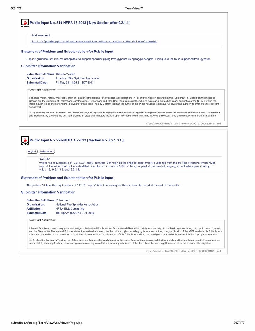
6/21/13 TerraView™
submittals.nfpa.org/TerraViewWeb/ViewerPage.jsp 207/477
Public Input No. 519-NFPA 13-2013 [ New Section after 9.2.1.1 ]
Add new text:
9.2.1.1.3 Sprinkler piping shall not be supported from ceilings of gypsum or other similar soft material.
Statement of Problem and Substantiation for Public Input
Explicit guidance that it is not acceptable to support sprinkler piping from gypsum using toggle hangers. Piping is found to be supported from gypsum.
Submitter Information Verification
Submitter Full Name:Thomas Wellen
Organization: American Fire Sprinkler Association
Submittal Date: Fri May 31 14:55:21 EDT 2013
Copyright Assignment
I, Thomas Wellen, hereby irrevocably grant and assign to the National Fire Protection Association (NFPA) all and full rights in copyright in this Public Input (including both the Proposed
Change and the Statement of Problem and Substantiation). I understand and intend that I acquire no rights, including rights as a joint author, in any publication of the NFPA in w hich this
Public Input in this or another similar or derivative form is used. I hereby w arrant that I am the author of this Public Input and that I have full pow er and authority to enter into this copyright
assignment.
By checking this box I aff irm that I am Thomas Wellen, and I agree to be legally bound by the above Copyright Assignment and the terms and conditions contained therein. I understand
and intend that, by checking this box, I am creating an electronic signature that w ill, upon my submission of this form, have the same legal force and effect as a handw ritten signature
Public Input No. 226-NFPA 13-2013 [ Section No. 9.2.1.3.1 ]
Original Hide Markup
9.2.1.3.1
Unless the requirements of 9.2.1.3.3 apply, sprinkler Sprinkler piping shall be substantially supported from the building structure, which mustsupport the added load of the water-filled pipe plus a minimum of 250 lb (114 kg) applied at the point of hanging, except where permitted by9.2.1.1.2, 9.2.1.3.3, and 9.2.1.4.1.
Statement of Problem and Substantiation for Public Input
The preface "Unless the requirements of 9.2.1.3.1 apply" is not necessary as this provision is stated at the end of the section.
Submitter Information Verification
Submitter Full Name:Roland Asp
Organization: National Fire Sprinkler Association
Affilliation: NFSA E&S Committee
Submittal Date: Thu Apr 25 09:29:54 EDT 2013
Copyright Assignment
I, Roland Asp, hereby irrevocably grant and assign to the National Fire Protection Association (NFPA) all and full rights in copyright in this Public Input (including both the Proposed Change
and the Statement of Problem and Substantiation). I understand and intend that I acquire no rights, including rights as a joint author, in any publication of the NFPA in w hich this Public Input in
this or another similar or derivative form is used. I hereby w arrant that I am the author of this Public Input and that I have full pow er and authority to enter into this copyright assignment.
By checking this box I aff irm that I am Roland Asp, and I agree to be legally bound by the above Copyright Assignment and the terms and conditions contained therein. I understand and
intend that, by checking this box, I am creating an electronic signature that w ill, upon my submission of this form, have the same legal force and effect as a handw ritten signature
/TerraView/Content/13-2013.ditamap/2/C1370026521434.xml
/TerraView/Content/13-2013.ditamap/2/C1366896594841.xml
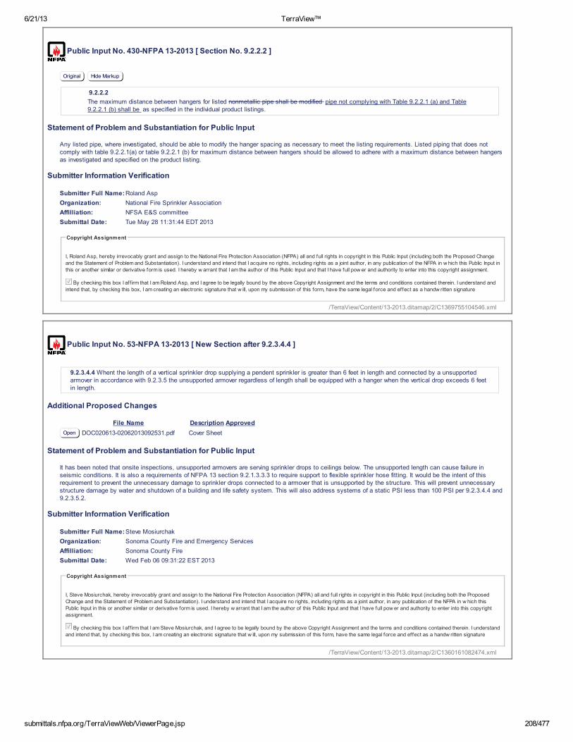
6/21/13 TerraView™
submittals.nfpa.org/TerraViewWeb/ViewerPage.jsp 208/477
Public Input No. 430-NFPA 13-2013 [ Section No. 9.2.2.2 ]
Original Hide Markup
9.2.2.2
The maximum distance between hangers for listed nonmetallic pipe shall be modified pipe not complying with Table 9.2.2.1 (a) and Table9.2.2.1 (b) shall be as specified in the individual product listings.
Statement of Problem and Substantiation for Public Input
Any listed pipe, where investigated, should be able to modify the hanger spacing as necessary to meet the listing requirements. Listed piping that does not comply with table 9.2.2.1(a) or table 9.2.2.1 (b) for maximum distance between hangers should be allowed to adhere with a maximum distance between hangers as investigated and specified on the product listing.
Submitter Information Verification
Submitter Full Name:Roland Asp
Organization: National Fire Sprinkler Association
Affilliation: NFSA E&S committee
Submittal Date: Tue May 28 11:31:44 EDT 2013
Copyright Assignment
I, Roland Asp, hereby irrevocably grant and assign to the National Fire Protection Association (NFPA) all and full rights in copyright in this Public Input (including both the Proposed Change
and the Statement of Problem and Substantiation). I understand and intend that I acquire no rights, including rights as a joint author, in any publication of the NFPA in w hich this Public Input in
this or another similar or derivative form is used. I hereby w arrant that I am the author of this Public Input and that I have full pow er and authority to enter into this copyright assignment.
By checking this box I aff irm that I am Roland Asp, and I agree to be legally bound by the above Copyright Assignment and the terms and conditions contained therein. I understand and
intend that, by checking this box, I am creating an electronic signature that w ill, upon my submission of this form, have the same legal force and effect as a handw ritten signature
Public Input No. 53-NFPA 13-2013 [ New Section after 9.2.3.4.4 ]
9.2.3.4.4 Whent the length of a vertical sprinkler drop supplying a pendent sprinkler is greater than 6 feet in length and connected by a unsupportedarmover in accordance with 9.2.3.5 the unsupported armover regardless of length shall be equipped with a hanger when the vertical drop exceeds 6 feetin length.
Additional Proposed Changes
File Name Description Approved
Open DOC020613-02062013092531.pdf Cover Sheet
Statement of Problem and Substantiation for Public Input
It has been noted that onsite inspections, unsupported armovers are serving sprinkler drops to ceilings below. The unsupported length can cause failure in seismic conditions. It is also a requirements of NFPA 13 section 9.2.1.3.3.3 to require support to flexible sprinkler hose fitting. It would be the intent of this requirement to prevent the unnecessary damage to sprinkler drops connected to a armover that is unsupported by the structure. This will prevent unnecessary structure damage by water and shutdown of a building and life safety system. This will also address systems of a static PSI less than 100 PSI per 9.2.3.4.4 and 9.2.3.5.2.
Submitter Information Verification
Submitter Full Name:Steve Mosiurchak
Organization: Sonoma County Fire and Emergency Services
Affilliation: Sonoma County Fire
Submittal Date: Wed Feb 06 09:31:22 EST 2013
Copyright Assignment
I, Steve Mosiurchak, hereby irrevocably grant and assign to the National Fire Protection Association (NFPA) all and full rights in copyright in this Public Input (including both the Proposed
Change and the Statement of Problem and Substantiation). I understand and intend that I acquire no rights, including rights as a joint author, in any publication of the NFPA in w hich this
Public Input in this or another similar or derivative form is used. I hereby w arrant that I am the author of this Public Input and that I have full pow er and authority to enter into this copyright
assignment.
By checking this box I aff irm that I am Steve Mosiurchak, and I agree to be legally bound by the above Copyright Assignment and the terms and conditions contained therein. I understand
and intend that, by checking this box, I am creating an electronic signature that w ill, upon my submission of this form, have the same legal force and effect as a handw ritten signature
/TerraView/Content/13-2013.ditamap/2/C1369755104546.xml
/TerraView/Content/13-2013.ditamap/2/C1360161082474.xml

6/21/13 TerraView™
submittals.nfpa.org/TerraViewWeb/ViewerPage.jsp 209/477
Public Input No. 529-NFPA 13-2013 [ Section No. 9.2.3.4.4.4 ]
Original Hide Markup
9.2.3.4.4.4
The Except where flexible sprinkler hose fittings that are attached to the ceiling structure in accordance with their Listing are used, the hangerclosest to the sprinkler shall be of a type that prevents upward movement of the pipe.
Statement of Problem and Substantiation for Public Input
When flexible hoses are installed in accordance with the Listing, the sprinkler is fixed to the ceiling, and no additional means are necessary to prevent upward thrust.
Submitter Information Verification
Submitter Full Name:Peter Thomas
Organization: Victaulic Company
Submittal Date: Fri May 31 15:18:41 EDT 2013
Copyright Assignment
I, Peter Thomas, hereby irrevocably grant and assign to the National Fire Protection Association (NFPA) all and full rights in copyright in this Public Input (including both the Proposed Change
and the Statement of Problem and Substantiation). I understand and intend that I acquire no rights, including rights as a joint author, in any publication of the NFPA in w hich this Public Input in
this or another similar or derivative form is used. I hereby w arrant that I am the author of this Public Input and that I have full pow er and authority to enter into this copyright assignment.
By checking this box I aff irm that I am Peter Thomas, and I agree to be legally bound by the above Copyright Assignment and the terms and conditions contained therein. I understand and
intend that, by checking this box, I am creating an electronic signature that w ill, upon my submission of this form, have the same legal force and effect as a handw ritten signature
Public Input No. 356-NFPA 13-2013 [ New Section after 9.2.3.5.2.2 ]
9.2.3.5.2.3
Where the armover exceeds the maximum unspupported length of 9.2.3.5.2.1, a hanger shall be installed so that the distance from the end sprinkler ordrop nipple to the hanger is not greater than 12 inches for steel or 6 inches for copper.
Statement of Problem and Substantiation for Public Input
For a armover exceeding 12 inches in length, section 9.2.3.5.2.1 requires a hanger, but it does not require the hanger to be within 12 inches of the end. Without this new section, the standard allows unsupported armovers in excess of 12 inches.
Submitter Information Verification
Submitter Full Name:Roland Asp
Organization: National Fire Sprinkler Association
Affilliation: NFSA E& S Committee
Submittal Date: Wed May 22 16:40:08 EDT 2013
Copyright Assignment
I, Roland Asp, hereby irrevocably grant and assign to the National Fire Protection Association (NFPA) all and full rights in copyright in this Public Input (including both the Proposed Change
and the Statement of Problem and Substantiation). I understand and intend that I acquire no rights, including rights as a joint author, in any publication of the NFPA in w hich this Public Input in
this or another similar or derivative form is used. I hereby w arrant that I am the author of this Public Input and that I have full pow er and authority to enter into this copyright assignment.
By checking this box I aff irm that I am Roland Asp, and I agree to be legally bound by the above Copyright Assignment and the terms and conditions contained therein. I understand and
intend that, by checking this box, I am creating an electronic signature that w ill, upon my submission of this form, have the same legal force and effect as a handw ritten signature
/TerraView/Content/13-2013.ditamap/2/C1370027921729.xml
/TerraView/Content/13-2013.ditamap/2/C1369255208890.xml

6/21/13 TerraView™
submittals.nfpa.org/TerraViewWeb/ViewerPage.jsp 210/477
Public Input No. 532-NFPA 13-2013 [ Section No. 9.2.3.5.2.2 ]
Original Hide Markup
9.2.3.5.2.2
The Except where flexible sprinkler hose fittings that are attached to the ceiling structure in accordance with their Listing are used, the hangerclosest to the sprinkler shall be of a type that prevents upward movement of the pipe.
Statement of Problem and Substantiation for Public Input
When flexible hoses are installed in accordance with the Listing, the sprinkler is fixed to the ceiling, and no additional means are necessary to prevent upward thrust.
Submitter Information Verification
Submitter Full Name:Peter Thomas
Organization: Victaulic Company
Submittal Date: Fri May 31 15:30:54 EDT 2013
Copyright Assignment
I, Peter Thomas, hereby irrevocably grant and assign to the National Fire Protection Association (NFPA) all and full rights in copyright in this Public Input (including both the Proposed Change
and the Statement of Problem and Substantiation). I understand and intend that I acquire no rights, including rights as a joint author, in any publication of the NFPA in w hich this Public Input in
this or another similar or derivative form is used. I hereby w arrant that I am the author of this Public Input and that I have full pow er and authority to enter into this copyright assignment.
By checking this box I aff irm that I am Peter Thomas, and I agree to be legally bound by the above Copyright Assignment and the terms and conditions contained therein. I understand and
intend that, by checking this box, I am creating an electronic signature that w ill, upon my submission of this form, have the same legal force and effect as a handw ritten signature
Public Input No. 381-NFPA 13-2013 [ Section No. 9.2.4.1 ]
Original Hide Markup
9.2.4.1
Unless the requirements of 9.2.4.2 , through 9.2.4. 3, 9.2.4.4 , 9.2.4.5 , or 9.2.4. 6 are met, hangers for mains shall be in accordancewith 9.2.2 , between each branch line, or on each section of pipe, whichever is the lesser dimension.
Statement of Problem and Substantiation for Public Input
It is cleaner and more user friendly to say "through" than it is to make a long list.
Submitter Information Verification
Submitter Full Name:Roland Asp
Organization: National Fire Sprinkler Association
Affilliation: NFSA E&S Committee
Submittal Date: Thu May 23 15:01:39 EDT 2013
Copyright Assignment
I, Roland Asp, hereby irrevocably grant and assign to the National Fire Protection Association (NFPA) all and full rights in copyright in this Public Input (including both the Proposed Change
and the Statement of Problem and Substantiation). I understand and intend that I acquire no rights, including rights as a joint author, in any publication of the NFPA in w hich this Public Input in
this or another similar or derivative form is used. I hereby w arrant that I am the author of this Public Input and that I have full pow er and authority to enter into this copyright assignment.
By checking this box I aff irm that I am Roland Asp, and I agree to be legally bound by the above Copyright Assignment and the terms and conditions contained therein. I understand and
intend that, by checking this box, I am creating an electronic signature that w ill, upon my submission of this form, have the same legal force and effect as a handw ritten signature
/TerraView/Content/13-2013.ditamap/2/C1370028654814.xml
/TerraView/Content/13-2013.ditamap/2/C1369335699593.xml

6/21/13 TerraView™
submittals.nfpa.org/TerraViewWeb/ViewerPage.jsp 211/477
Public Input No. 263-NFPA 13-2013 [ Section No. 9.2.6 ]
Original Hide Markup
9.2.6 * Pipe Stands.
9.2.6.1
Pipe stands shall be sized to support a minimum of five times the weight of the water-filled pipe plus 250 lb (114 kg).
9.2.6.2
The pipe stand base shall be secured by an approved method.
9.2.6.3
Where pipe stands are utilized, they shall be approved.
9.2.6.4 Pipe stands used to support piping shall be in accordance with Table 9.2.6.4 to determine maximum heights for pipe standssupporting various diameters of piping.
9.2.6.5 Pipe stands shall be constructed of schedule 40 pipe and a threaded malleable iron or welded steel flange base.
9.2.6.6 Pipe stands differing from the requirements of 9.2.6 shall be allowed where they are specifically listed for such use and installed inaccordance with their listing.
Additional Proposed Changes
File Name Description Approved
Open Pipe_Stand_Table_-_13_-_2016_edition.docx Table 9.2.6.4
Statement of Problem and Substantiation for Public Input
NFPA 13 currently lacks sufficient information for guiding system designers or installers in the proper sizing of pipe stands. This information has been contained in NFPA 15, and has been successfully utilized in fixed spray systems without any know issues for years. The pipe stand sizing and height limitations contained in this proposed change come directly from NFPA 15, 2012 edition. Since fixed spray systems are often subjected to higher reaction loads than typical NFPA 13 systems, the proposed pipe stand sizing requirements should be more than adequate. Including this additional information in the pipe stand section of Chapter 9 of NFPA 13 would potentially save a designer or installer from having to engage an engineer just to size a pipe stand to support a header, for example.
Submitter Information Verification
Submitter Full Name:E. Moore
Organization: S & S Sprinkler Company, LLC
Submittal Date: Wed May 08 15:02:26 EDT 2013
Copyright Assignment
I, E. Moore, hereby irrevocably grant and assign to the National Fire Protection Association (NFPA) all and full rights in copyright in this Public Input (including both the Proposed Change and
the Statement of Problem and Substantiation). I understand and intend that I acquire no rights, including rights as a joint author, in any publication of the NFPA in w hich this Public Input in this
or another similar or derivative form is used. I hereby w arrant that I am the author of this Public Input and that I have full pow er and authority to enter into this copyright assignment.
By checking this box I aff irm that I am E. Moore, and I agree to be legally bound by the above Copyright Assignment and the terms and conditions contained therein. I understand and
intend that, by checking this box, I am creating an electronic signature that w ill, upon my submission of this form, have the same legal force and effect as a handw ritten signature
/TerraView/Content/13-2013.ditamap/2/C1368039746909.xml

Table 9.2.6.4 Maximum Pipe Stand Heights System Pipe
Diameter Pipe Stand Diameter
1 ½ in. 2 in. 2 ½ in. 3 in. 4 in. 1 ½ in. 10 ft 14 ft 18 ft 28 ft 30 ft
2 in. 8 ft 12 ft 16 ft 26 ft 30 ft 2 ½ in. 6 ft 10 ft 14 ft 24 ft 30 ft 3 in. ---- 8 ft 12 ft 22 ft 30 ft
>3 in. up to and including 8 in.
---- ---- ---- ---- 10 ft
For SI units, 1 in. = 25.4 mm; 1 ft = 0.3048 m.

6/21/13 TerraView™
submittals.nfpa.org/TerraViewWeb/ViewerPage.jsp 212/477
Public Input No. 227-NFPA 13-2013 [ Section No. 9.3.4.2 ]
Original Hide Markup
9.3.4.2
Unless the requirements of 9.3.4.3 through 9.3.4.7 or 9.3.4.10 are met, where pipe passes through holes in platforms, foundations, walls, orfloors, the holes shall be sized such that the diameter of the holes is nominally 2 in. (50 mm) larger than the pipe for pipe 1 in. (25 mm) nominalto 3 1⁄2 in. (90 mm) nominal and 4 in. (100 mm) larger than the pipe for pipe 4 in. (100 mm) nominal and larger.
Statement of Problem and Substantiation for Public Input
Section 9.3.4.10 was added to the 2013 edition of NFPA 13 but was not added to section 9.3.4.2, which allows exceptions to the 2 in. clearance requirement.
Submitter Information Verification
Submitter Full Name:Roland Asp
Organization: National Fire Sprinkler Association
Affilliation: NFSA E&S Committee
Submittal Date: Thu Apr 25 09:36:59 EDT 2013
Copyright Assignment
I, Roland Asp, hereby irrevocably grant and assign to the National Fire Protection Association (NFPA) all and full rights in copyright in this Public Input (including both the Proposed Change
and the Statement of Problem and Substantiation). I understand and intend that I acquire no rights, including rights as a joint author, in any publication of the NFPA in w hich this Public Input in
this or another similar or derivative form is used. I hereby w arrant that I am the author of this Public Input and that I have full pow er and authority to enter into this copyright assignment.
By checking this box I aff irm that I am Roland Asp, and I agree to be legally bound by the above Copyright Assignment and the terms and conditions contained therein. I understand and
intend that, by checking this box, I am creating an electronic signature that w ill, upon my submission of this form, have the same legal force and effect as a handw ritten signature
Public Input No. 520-NFPA 13-2013 [ Section No. 9.3.4.5 ]
Original Hide Markup
9.3.4.5
No clearance shall be required if flexible couplings are located within 1 ft (305 mm) of each side of a wall, floor, platform, or foundation wall orwithin 12 in. (305 mm) above and within 24 in. (610 mm) below the floors in multistory buildings, platforms, or foundations .
Statement of Problem and Substantiation for Public Input
9.3.4.5 says that flexible couplings have to be within 1 ft (305 mm) of each side of a floor, platform, or foundation to omit the clearance hole. 9.3.2.3.1 in no. 2 says within 24 in. below the floor in multistory buildings. As such, if a flexible coupling is located more than 12 in. and less than 24 in. below a floor, a clearance hole is required by 9.3.4.5. Increasing the coupling distance to within 24 in. below the floor, platform, or foundation in 9.3.4.5 will conform with 9.3.2.3.1(2).
Submitter Information Verification
Submitter Full Name:Thomas Wellen
Organization: American Fire Sprinkler Association
Submittal Date: Fri May 31 14:57:28 EDT 2013
Copyright Assignment
I, Thomas Wellen, hereby irrevocably grant and assign to the National Fire Protection Association (NFPA) all and full rights in copyright in this Public Input (including both the Proposed
Change and the Statement of Problem and Substantiation). I understand and intend that I acquire no rights, including rights as a joint author, in any publication of the NFPA in w hich this
Public Input in this or another similar or derivative form is used. I hereby w arrant that I am the author of this Public Input and that I have full pow er and authority to enter into this copyright
assignment.
By checking this box I aff irm that I am Thomas Wellen, and I agree to be legally bound by the above Copyright Assignment and the terms and conditions contained therein. I understand
and intend that, by checking this box, I am creating an electronic signature that w ill, upon my submission of this form, have the same legal force and effect as a handw ritten signature
/TerraView/Content/13-2013.ditamap/2/C1366897019780.xml
/TerraView/Content/13-2013.ditamap/2/C1370026648848.xml

6/21/13 TerraView™
submittals.nfpa.org/TerraViewWeb/ViewerPage.jsp 213/477
Public Input No. 490-NFPA 13-2013 [ Section No. 9.3.4.9 ]
Original Hide Markup
9.3.4.9
Clearance from structural members not penetrated or used, collectively or independently, to support the piping shall be at least 2 in. (50 mm)except that for piping where lateral bracing is omitted per Section 9 . 3.5.5.10, the clearance shall be at least 4 in. (100 mm).
Additional Proposed Changes
File Name Description Approved
Open Pipe_swing.pdf Graphic showing the horizontal deflection due to pipe swing from a short rod hanger
Statement of Problem and Substantiation for Public Input
Where lateral bracing is omitted, the deflection of the pipe (and in the case of cross mains, any attached pipe) can be large. If the angle from vertical is 30 degrees this deflection is 4" and the deflection could be more than 5.5 inches if the angle from vertical approached 45 degrees. Clearance, particularly to sprinklers, should be larger where bracing is omitted.
Related Public Inputs for This Document
Related Input Relationship
Open Public Input No. 489-NFPA 13-2013 [Section No. 9.3.5.5.10]
Submitter Information Verification
Submitter Full Name:Christopher Deneff
Organization: FM Global
Submittal Date: Fri May 31 10:13:41 EDT 2013
Copyright Assignment
I, Christopher Deneff, hereby irrevocably grant and assign to the National Fire Protection Association (NFPA) all and full rights in copyright in this Public Input (including both the Proposed
Change and the Statement of Problem and Substantiation). I understand and intend that I acquire no rights, including rights as a joint author, in any publication of the NFPA in w hich this
Public Input in this or another similar or derivative form is used. I hereby w arrant that I am the author of this Public Input and that I have full pow er and authority to enter into this copyright
assignment.
By checking this box I aff irm that I am Christopher Deneff, and I agree to be legally bound by the above Copyright Assignment and the terms and conditions contained therein. I
understand and intend that, by checking this box, I am creating an electronic signature that w ill, upon my submission of this form, have the same legal force and effect as a handw ritten
signature
/TerraView/Content/13-2013.ditamap/2/C1370009621678.xml
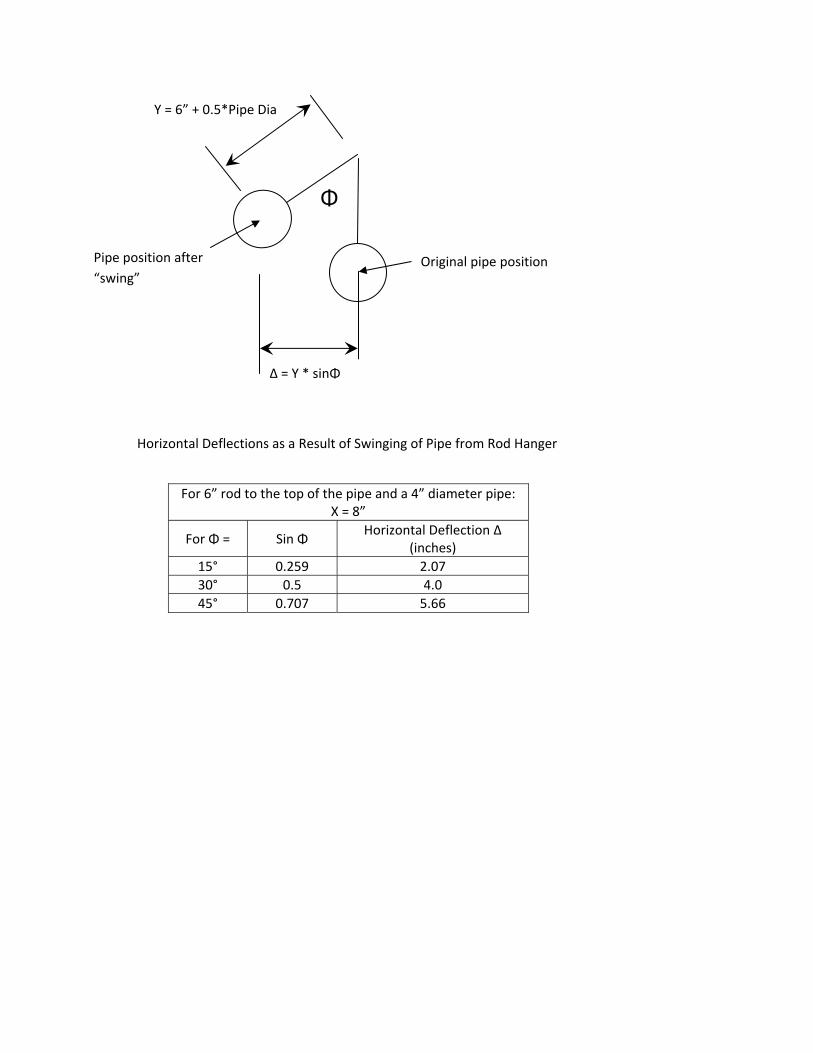
For 6” rod to the top of the pipe and a 4” diameter pipe:
X = 8”
For Φ = Sin Φ Horizontal Deflection Δ (inches)
15° 0.259 2.07 30° 0.5 4.0 45° 0.707 5.66
Φ
Y = 6” + 0.5*Pipe Dia
Original pipe position Pipe position after “swing”
Δ = Y * sinΦ
Horizontal Deflections as a Result of Swinging of Pipe from Rod Hanger

6/21/13 TerraView™
submittals.nfpa.org/TerraViewWeb/ViewerPage.jsp 214/477
Public Input No. 554-NFPA 13-2013 [ Section No. 9.3.4.10 ]
Original Hide Markup
9.3.4.10
No clearance shall be required at the point of support where piping is supported by holes through structural members as permitted by9.1.1.6.3 .
Additional Proposed Changes
File Name Description Approved
Open NFPAPublicInputForm_9.3.4.10.docx Cover Sheet
Statement of Problem and Substantiation for Public Input
The lack of clearance at the other coordinates in/on the bore are problematic.
Submitter Information Verification
Submitter Full Name:Kraig Kirschner
Organization: AFCON
Submittal Date: Mon Jun 03 10:33:12 EDT 2013
Copyright Assignment
I, Kraig Kirschner, hereby irrevocably grant and assign to the National Fire Protection Association (NFPA) all and full rights in copyright in this Public Input (including both the Proposed
Change and the Statement of Problem and Substantiation). I understand and intend that I acquire no rights, including rights as a joint author, in any publication of the NFPA in w hich this
Public Input in this or another similar or derivative form is used. I hereby w arrant that I am the author of this Public Input and that I have full pow er and authority to enter into this copyright
assignment.
By checking this box I aff irm that I am Kraig Kirschner, and I agree to be legally bound by the above Copyright Assignment and the terms and conditions contained therein. I understand
and intend that, by checking this box, I am creating an electronic signature that w ill, upon my submission of this form, have the same legal force and effect as a handw ritten signature
Public Input No. 394-NFPA 13-2013 [ Section No. 9.3.5.2.3 ]
Original Hide Markup
9.3.5.2.3
The listed loads shall be reduced as shown in Table 9.3.5.2.3 for installations where the brace is less than 90 degrees from vertical.
Table 9.3.5.2.3 Allowable Horizontal Load on Brace Assemblies Based on Weakest Component of Brace Assembly
Brace Angle Degrees
from VerticalAllowable Horizontal Load
30 to 44 Listed load rating divided by 2.000
45 to 59 Listed load rating divided by 1.414
60 to 89 Listed load rating divided by 1.155
90 Listed load rating
Statement of Problem and Substantiation for Public Input
All we have proposed to change here is adding the word "listed" before "loads". People are inappropriately applying this table to the values in the other tables of NFPA 13 that already take the angle into account. It would be helpful to clarify that the reduction factors only applied to the listed load discussed in this section.
Submitter Information Verification
Submitter Full Name:Roland Asp
Organization: National Fire Sprinkler Association
Affilliation: NFSA E&S Committee
Submittal Date: Thu May 23 16:07:05 EDT 2013
Copyright Assignment
I, Roland Asp, hereby irrevocably grant and assign to the National Fire Protection Association (NFPA) all and full rights in copyright in this Public Input (including both the Proposed Change
and the Statement of Problem and Substantiation). I understand and intend that I acquire no rights, including rights as a joint author, in any publication of the NFPA in w hich this Public Input in
this or another similar or derivative form is used. I hereby w arrant that I am the author of this Public Input and that I have full pow er and authority to enter into this copyright assignment.
By checking this box I aff irm that I am Roland Asp, and I agree to be legally bound by the above Copyright Assignment and the terms and conditions contained therein. I understand and
intend that, by checking this box, I am creating an electronic signature that w ill, upon my submission of this form, have the same legal force and effect as a handw ritten signature
/TerraView/Content/13-2013.ditamap/2/C1370269992696.xml
/TerraView/Content/13-2013.ditamap/2/C1369339625969.xml
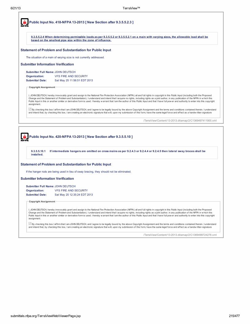
6/21/13 TerraView™
submittals.nfpa.org/TerraViewWeb/ViewerPage.jsp 215/477
Public Input No. 418-NFPA 13-2013 [ New Section after 9.3.5.5.2.3 ]
9.3.5.5.2.4 When determining permissible loads as per 9.3.5.5.2 or 9.3.5.5.2.1 on a main with varying sizes, the allowable load shall bebased on the smallest pipe size within the zone of influence.
Statement of Problem and Substantiation for Public Input
The situation of a main of varying size is not currently addressed.
Submitter Information Verification
Submitter Full Name:JOHN DEUTSCH
Organization: VFS FIRE AND SECURITY
Submittal Date: Sat May 25 11:56:51 EDT 2013
Copyright Assignment
I, JOHN DEUTSCH, hereby irrevocably grant and assign to the National Fire Protection Association (NFPA) all and full rights in copyright in this Public Input (including both the Proposed
Change and the Statement of Problem and Substantiation). I understand and intend that I acquire no rights, including rights as a joint author, in any publication of the NFPA in w hich this
Public Input in this or another similar or derivative form is used. I hereby w arrant that I am the author of this Public Input and that I have full pow er and authority to enter into this copyright
assignment.
By checking this box I aff irm that I am JOHN DEUTSCH, and I agree to be legally bound by the above Copyright Assignment and the terms and conditions contained therein. I understand
and intend that, by checking this box, I am creating an electronic signature that w ill, upon my submission of this form, have the same legal force and effect as a handw ritten signature
Public Input No. 420-NFPA 13-2013 [ New Section after 9.3.5.5.10 ]
9.3.5.5.10.1 If intermediate hangers are omitted on cross mains as per 9.2.4.3 or 9.2.4.4 or 9.2.4.5 then lateral sway braces shall beinstalled.
Statement of Problem and Substantiation for Public Input
If the hanger rods are being used in lieu of sway bracing, they should not be eliminated.
Submitter Information Verification
Submitter Full Name:JOHN DEUTSCH
Organization: VFS FIRE AND SECURITY
Submittal Date: Sat May 25 12:35:24 EDT 2013
Copyright Assignment
I, JOHN DEUTSCH, hereby irrevocably grant and assign to the National Fire Protection Association (NFPA) all and full rights in copyright in this Public Input (including both the Proposed
Change and the Statement of Problem and Substantiation). I understand and intend that I acquire no rights, including rights as a joint author, in any publication of the NFPA in w hich this
Public Input in this or another similar or derivative form is used. I hereby w arrant that I am the author of this Public Input and that I have full pow er and authority to enter into this copyright
assignment.
By checking this box I aff irm that I am JOHN DEUTSCH, and I agree to be legally bound by the above Copyright Assignment and the terms and conditions contained therein. I understand
and intend that, by checking this box, I am creating an electronic signature that w ill, upon my submission of this form, have the same legal force and effect as a handw ritten signature
/TerraView/Content/13-2013.ditamap/2/C1369497411900.xml
/TerraView/Content/13-2013.ditamap/2/C1369499724278.xml

6/21/13 TerraView™
submittals.nfpa.org/TerraViewWeb/ViewerPage.jsp 216/477
Public Input No. 395-NFPA 13-2013 [ Section No. 9.3.5.5.10 ]
Original Hide Markup
9.3.5.5.10 *
The requirements of 9.3.5. 3 5 shall not apply to pipes individually supported by rods less than 6 in. (152 mm) long measured between thetop of the pipe and the point of attachment to the building structure.
Statement of Problem and Substantiation for Public Input
Section 9.3.5.5 is the correct section number. The 2013 edition was in error when a renumbering of the section occurred.
Submitter Information Verification
Submitter Full Name:Roland Asp
Organization: National Fire Sprinkler Association
Affilliation: NFSA E&S Committee
Submittal Date: Thu May 23 16:14:01 EDT 2013
Copyright Assignment
I, Roland Asp, hereby irrevocably grant and assign to the National Fire Protection Association (NFPA) all and full rights in copyright in this Public Input (including both the Proposed Change
and the Statement of Problem and Substantiation). I understand and intend that I acquire no rights, including rights as a joint author, in any publication of the NFPA in w hich this Public Input in
this or another similar or derivative form is used. I hereby w arrant that I am the author of this Public Input and that I have full pow er and authority to enter into this copyright assignment.
By checking this box I aff irm that I am Roland Asp, and I agree to be legally bound by the above Copyright Assignment and the terms and conditions contained therein. I understand and
intend that, by checking this box, I am creating an electronic signature that w ill, upon my submission of this form, have the same legal force and effect as a handw ritten signature
Public Input No. 419-NFPA 13-2013 [ Section No. 9.3.5.5.10 ]
Original Hide Markup
9.3.5.5.10 *
The requirements of 9.3.5. 3 5.1 shall not apply to pipes 4" diameter and smaller when individually supported by rods less than 6 in. (152mm) long measured between the top of the pipe and the point of attachment to the building structure and when the horizontal seismic load onthe hanger does not exceed the values in table 9 . 3.5.5.10 based on pipe size and material. The horizontal seismic load shall be determined asper 9.3.5.9.
Additional Proposed Changes
File Name Description Approved
Open Table_9.3.5.5.10.xlsx Table 9.3.5.5.10
Open Table_9.3.5.5.10_substantiation.xlsx Substantiation only - Not to be included in actual Standard
Statement of Problem and Substantiation for Public Input
When sprinkler pipe is braced, the bracing is limited by the zone of influence method but there are no limits when braces are omitted and short hanger rods are used, a cross main is allowed unlimited tributary loads from branch lines if hung with 6" rods.
Submitter Information Verification
Submitter Full Name:JOHN DEUTSCH
Organization: VFS FIRE AND SECURITY
Submittal Date: Sat May 25 12:10:34 EDT 2013
Copyright Assignment
I, JOHN DEUTSCH, hereby irrevocably grant and assign to the National Fire Protection Association (NFPA) all and full rights in copyright in this Public Input (including both the Proposed
Change and the Statement of Problem and Substantiation). I understand and intend that I acquire no rights, including rights as a joint author, in any publication of the NFPA in w hich this
Public Input in this or another similar or derivative form is used. I hereby w arrant that I am the author of this Public Input and that I have full pow er and authority to enter into this copyright
assignment.
By checking this box I aff irm that I am JOHN DEUTSCH, and I agree to be legally bound by the above Copyright Assignment and the terms and conditions contained therein. I understand
and intend that, by checking this box, I am creating an electronic signature that w ill, upon my submission of this form, have the same legal force and effect as a handw ritten signature
/TerraView/Content/13-2013.ditamap/2/C1369340041285.xml
/TerraView/Content/13-2013.ditamap/2/C1369498234744.xml

Pipe Size Steel Copper CPVC 3/4 na 7 2
1 25 10 41 1/4 35 15 71 1/2 55 20 10
2 75 40 182 1/2 120 60 30
3 165 80 603 1/2 200 135 na
4 250 175 na

6/21/13 TerraView™
submittals.nfpa.org/TerraViewWeb/ViewerPage.jsp 217/477
Public Input No. 489-NFPA 13-2013 [ Section No. 9.3.5.5.10 ]
Original Hide Markup
9.3.5.5.10 *
The requirements of 9.3.5. 3 5 shall not apply to pipes branch lines where all of the hangers are individually supported by rods less than 6in. (152 mm) long measured between the top of the pipe and the point of attachment to the building structure. The rod hanger connections to thestructure must be configured such that they do not develop moments due to swinging of the branch line (e.g., using a swivel connector).
Additional Proposed Changes
File Name Description Approved
Open Pipe_swing.pdf Graphic showing the horizontal displacements associated with a swinging pipe
Statement of Problem and Substantiation for Public Input
The current section allows omission of lateral bracing (I believe the reference to Section 9.3.5.3 is incorrect, should be 9.3.5.5) on all pipes using short rods. This allows large displacements (on the order of 4" for even a modest swing of 30 degrees from vertical - see attached graphic). Looking at a cross main in particular, all attached branch lines will deflect possibly allowing impact on sprinklers, forcing their hangers to accommodate large deflections without damage, and putting stress on couplings. Additionally, the tributary force on a cross main hanger could be extremely large since it could include long lengths of unrestrained branch lines. There is no way to determine the lateral capacity of a hanger, since they are not designed for this purpose. Likewise, for a feed main, the lateral force on the hanger could be very large; again, there is no way to determine if the hanger is adequate to resist these forces and these hangers could be attached using methods adequate for vertical forces but questionable for lateral forces (e.g., using C-clamps). Lengths of feed mains and cross mains are limited so providing braces would not be overly expensive, and is justified based on the great consequences of a main failure. Branch lines are typically smaller and are individual pipes rather than a piping system such as cross mains. Although I do not think we have adequate information to be totally confident of the capacity of a branch line hanger to resist lateral forces, allowing the 6" rod exception seems reasonable for branch lines.
Submitter Information Verification
Submitter Full Name:Christopher Deneff
Organization: FM Global
Submittal Date: Fri May 31 09:44:56 EDT 2013
Copyright Assignment
I, Christopher Deneff, hereby irrevocably grant and assign to the National Fire Protection Association (NFPA) all and full rights in copyright in this Public Input (including both the Proposed
Change and the Statement of Problem and Substantiation). I understand and intend that I acquire no rights, including rights as a joint author, in any publication of the NFPA in w hich this
Public Input in this or another similar or derivative form is used. I hereby w arrant that I am the author of this Public Input and that I have full pow er and authority to enter into this copyright
assignment.
By checking this box I aff irm that I am Christopher Deneff, and I agree to be legally bound by the above Copyright Assignment and the terms and conditions contained therein. I
understand and intend that, by checking this box, I am creating an electronic signature that w ill, upon my submission of this form, have the same legal force and effect as a handw ritten
signature
/TerraView/Content/13-2013.ditamap/2/C1370007896399.xml

For 6” rod to the top of the pipe and a 4” diameter pipe:
X = 8”
For Φ = Sin Φ Horizontal Deflection Δ (inches)
15° 0.259 2.07 30° 0.5 4.0 45° 0.707 5.66
Φ
Y = 6” + 0.5*Pipe Dia
Original pipe position Pipe position after “swing”
Δ = Y * sinΦ
Horizontal Deflections as a Result of Swinging of Pipe from Rod Hanger

6/21/13 TerraView™
submittals.nfpa.org/TerraViewWeb/ViewerPage.jsp 218/477
Public Input No. 551-NFPA 13-2013 [ Section No. 9.3.5.5.10 ]
Original Hide Markup
9.3.5.5.10 *
The requirements of 9.3.5.3 shall not apply to pipes branch lines individually supported by rods less than 6 in. (152 mm) long measuredbetween the top of the pipe and the point of attachment to the building structure , and shall only be allowable when Cp does not exceed 1 . 0.
Additional Proposed Changes
File Name Description Approved
Open NFPAPublicInputForm_9.3.5.5.10.docx Cover Sheet
Statement of Problem and Substantiation for Public Input
In Chapter 9 and per ASCE 7 we adjust sway bracing to limit force on system piping to insure integrity of the system and its components. In conformance we evaluate the additive weight, quantify the Cp and address their effects on system pipe by type and size. It is not sound science, engineering or mechanics to assume the dampening effect of a 6” hanger rod is always sufficient to compensate for all the above variables such that none of the above protocol is necessary without defined parameters.
Submitter Information Verification
Submitter Full Name:Kraig Kirschner
Organization: AFCON
Submittal Date: Mon Jun 03 08:45:51 EDT 2013
Copyright Assignment
I, Kraig Kirschner, hereby irrevocably grant and assign to the National Fire Protection Association (NFPA) all and full rights in copyright in this Public Input (including both the Proposed
Change and the Statement of Problem and Substantiation). I understand and intend that I acquire no rights, including rights as a joint author, in any publication of the NFPA in w hich this
Public Input in this or another similar or derivative form is used. I hereby w arrant that I am the author of this Public Input and that I have full pow er and authority to enter into this copyright
assignment.
By checking this box I aff irm that I am Kraig Kirschner, and I agree to be legally bound by the above Copyright Assignment and the terms and conditions contained therein. I understand
and intend that, by checking this box, I am creating an electronic signature that w ill, upon my submission of this form, have the same legal force and effect as a handw ritten signature
/TerraView/Content/13-2013.ditamap/2/C1370263551001.xml
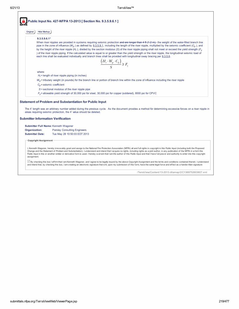
6/21/13 TerraView™
submittals.nfpa.org/TerraViewWeb/ViewerPage.jsp 219/477
Public Input No. 427-NFPA 13-2013 [ Section No. 9.3.5.9.6.1 ]
Original Hide Markup
9.3.5.9.6.1*
When riser nipples are provided in systems requiring seismic protection and are longer than 4 ft (1.2 m), the weight of the water-filled branch linepipe in the zone of influence (Wp ) as defined by 9.3.5.9.1, including the length of the riser nipple, multiplied by the seismic coefficient (Cp ), and
by the height of the riser nipple (Hr ), divided by the section modulus (S) of the riser nipple piping shall not meet or exceed the yield strength (Fy
) of the riser nipple piping. If the calculated value is equal to or greater than the yield strength or the riser nipple, the longitudinal seismic load ofeach line shall be evaluated individually and branch lines shall be provided with longitudinal sway bracing per 9.3.5.6.
where:
Hr = length of riser nipple piping (in inches)
Wp = tributary weight (in pounds) for the branch line or portion of branch line within the zone of influence including the riser nipple
Cp = seismic coefficient
S = sectional modulus of the riser nipple pipe
Fy= allowable yield strength of 30,000 psi for steel, 30,000 psi for copper (soldered), 8000 psi for CPVC
Statement of Problem and Substantiation for Public Input
The 4’ length was an arbitrary number added during the previous cycle. As the document provides a method for determining excessive forces on a riser nipple in areas requiring seismic protection, the 4’ value should be deleted.
Submitter Information Verification
Submitter Full Name:Kenneth Wagoner
Organization: Parsley Consulting Engineers
Submittal Date: Tue May 28 10:50:03 EDT 2013
Copyright Assignment
I, Kenneth Wagoner, hereby irrevocably grant and assign to the National Fire Protection Association (NFPA) all and full rights in copyright in this Public Input (including both the Proposed
Change and the Statement of Problem and Substantiation). I understand and intend that I acquire no rights, including rights as a joint author, in any publication of the NFPA in w hich this
Public Input in this or another similar or derivative form is used. I hereby w arrant that I am the author of this Public Input and that I have full pow er and authority to enter into this copyright
assignment.
By checking this box I aff irm that I am Kenneth Wagoner, and I agree to be legally bound by the above Copyright Assignment and the terms and conditions contained therein. I understand
and intend that, by checking this box, I am creating an electronic signature that w ill, upon my submission of this form, have the same legal force and effect as a handw ritten signature
/TerraView/Content/13-2013.ditamap/2/C1369752603607.xml

6/21/13 TerraView™
submittals.nfpa.org/TerraViewWeb/ViewerPage.jsp 220/477
Public Input No. 491-NFPA 13-2013 [ Section No. 9.3.5.9.6.1 ]
Original Hide Markup
9.3.5.9.6.1 *
When riser nipples are provided in systems requiring seismic protection and are longer than 4 ft (1.2 m), the weight of the water-filledbranch line pipe in the zone of influence ( W p ) as defined by 9.3.5.9.1 , including the length of the riser nipple, multiplied by the seismic
coefficient ( C p ), and by the height of the riser nipple ( H r ), divided by the section modulus ( S ) of the riser nipple piping shall not meet or
exceed the yield strength ( F y ) of the riser nipple piping nor the allowable bending capacity of the coupling . If the calculated value is equal to
or greater than the yield strength or strength of the riser nipple, the longitudinal seismic load of each line shall be evaluated individually andbranch lines shall be provided with longitudinal sway bracing per 9.3.5.6 .
where:
H r = length of riser nipple piping (in inches)
W p = tributary weight (in pounds) for the branch line or portion of branch line within the zone of influence including the riser nipple
C p = seismic coefficient
S = minimum sectional modulus of the riser nipple pipe (reduce for threaded connections)
F y = allowable yield strength of 30,000 psi for steel, 30,000 psi for copper (soldered), 8000 psi for CPVC
Statement of Problem and Substantiation for Public Input
There is no reason to limit this section to riser nipples greater than 4 ft, the calculation should be performed for all riser nipples. It is easy to come up with a scenario where a shorter riser nipple would be overstressed in bending. Additionally, any coupling should have adequate bending moment capacity and for threaded pipe the section modulus should be based on the section modulus considering the minimum root diameter.
Submitter Information Verification
Submitter Full Name:Christopher Deneff
Organization: FM Global
Submittal Date: Fri May 31 10:24:18 EDT 2013
Copyright Assignment
I, Christopher Deneff, hereby irrevocably grant and assign to the National Fire Protection Association (NFPA) all and full rights in copyright in this Public Input (including both the Proposed
Change and the Statement of Problem and Substantiation). I understand and intend that I acquire no rights, including rights as a joint author, in any publication of the NFPA in w hich this
Public Input in this or another similar or derivative form is used. I hereby w arrant that I am the author of this Public Input and that I have full pow er and authority to enter into this copyright
assignment.
By checking this box I aff irm that I am Christopher Deneff, and I agree to be legally bound by the above Copyright Assignment and the terms and conditions contained therein. I
understand and intend that, by checking this box, I am creating an electronic signature that w ill, upon my submission of this form, have the same legal force and effect as a handw ritten
signature
/TerraView/Content/13-2013.ditamap/2/C1370010258077.xml

6/21/13 TerraView™
submittals.nfpa.org/TerraViewWeb/ViewerPage.jsp 221/477
Public Input No. 275-NFPA 13-2013 [ Section No. 9.3.5.12.1 ]
Original Hide Markup
9.3.5.12.1 *
For individual fasteners, the loads determined in 9.3.5.9 shall not exceed the allowable loads provided in Figure 9.3.5.12.1 .
Figure 9.3.5.12.1 Maximum Loads for Various Types of Structures and Maximum Loads for Various Types of Fasteners to Structures.
Note: For wedge anchors the minimum concrete thickness must be at least 4” for 3/8” anchors, 6” for ½” & 5/8” anchors and 8” for ¾” anchors.The smallest concrete edge distance must be at least 4” for 3/8” anchors, 7½” for ½” anchors, 6” for 5/6” anchors and 9” for ¾” anchors.
Statement of Problem and Substantiation for Public Input
The Proposed Note is intended to be located in FIGURE 9.3.5.12.1 and under the Wedge Anchor Tables. In order to achieve the concretre anchor capacities reflected in the wedge anchor tables, the distacnce to the nearest edge of the concrete and the concrete thickness must be equal to or greaater than these values, which are in the ICC-ES Report that was used to prepare the tables.
Submitter Information Verification
Submitter Full Name:Daniel Duggan
Organization: Fire Sprinkler Design
Affilliation: Loos & Co., Inc.
Submittal Date: Sun May 12 15:56:45 EDT 2013
Copyright Assignment
I, Daniel Duggan, hereby irrevocably grant and assign to the National Fire Protection Association (NFPA) all and full rights in copyright in this Public Input (including both the Proposed Change
and the Statement of Problem and Substantiation). I understand and intend that I acquire no rights, including rights as a joint author, in any publication of the NFPA in w hich this Public Input in
this or another similar or derivative form is used. I hereby w arrant that I am the author of this Public Input and that I have full pow er and authority to enter into this copyright assignment.
By checking this box I aff irm that I am Daniel Duggan, and I agree to be legally bound by the above Copyright Assignment and the terms and conditions contained therein. I understand
and intend that, by checking this box, I am creating an electronic signature that w ill, upon my submission of this form, have the same legal force and effect as a handw ritten signature
Public Input No. 305-NFPA 13-2013 [ Section No. 9.3.5.12.1 ]
Original Hide Markup
/TerraView/Content/13-2013.ditamap/2/C1368388605955.xml

6/21/13 TerraView™
submittals.nfpa.org/TerraViewWeb/ViewerPage.jsp 222/477
9.3.5.12.1*
For individual fasteners, the loads determined in 9.3.5.9 shall not exceed the allowable loads provided in Figure 9.3.5.12.1.
Figure 9.3.5.12.1 Maximum Loads for Various Types of Structures and Maximum Loads for Various Types of Fasteners to Structures.
Additional Proposed Changes
File Name Description Approved
Open Fig_9_3_5_12_1_Proposed.pdf Proposed Tables for Figure 9.3.5.12.1 to replace the current tables for wedge anchors.
Open Support_for_Proposal_on_Fig_9_3_5_12_1.pdf Document supporting proposed replacement wedge anchor tables for Figure 9.3.5.12.1
Statement of Problem and Substantiation for Public Input
During the 2010 change cycle, the concrete anchor capacities for Figure 9.3.5.9.1 were revised to reflect values for anchors that had passed the ACI 355.2 seismic prequalification testing, as required by ASCE 7. These calculations were performed based on the ASD shear and tension values for seismic applications, as indicated in the only ICC-ES Report available at the time. Subsequent to the calculation of these anchor capacities for the 2010 Edition of NFPA-13, the ICC Evaluation Service discovered that ASD shear and tension values published in the ICC-ES Report were “unconservative” and issued a letter of “Clarification on the Use of the Conversion Factor “a” to Convert Strength Design (SD) to Allowable Stress Design (ASD)”. The simple fix per this clarification was to multiply that ASD seismic shear and tension values that were published in the ICC-ES Report by 1.1, which was the unconservative conversion factor, and then multiply by 1.43, which is the correct SD to ASD conversion factor for seismic applications. Since increasing the values by 1.1 and then dividing them by 1.43 is the same as simply multiplying them by 0.77, the wedge type anchor capacities in Figure 9.3.5.9.1 are corrected by this Proposal by simply multiplying them by 0.77.
Submitter Information Verification
Submitter Full Name:Daniel Duggan
Organization: Fire Sprinkler Design
Affilliation: Loos & Co., Inc.
Submittal Date: Tue May 14 18:33:24 EDT 2013
Copyright Assignment
I, Daniel Duggan, hereby irrevocably grant and assign to the National Fire Protection Association (NFPA) all and full rights in copyright in this Public Input (including both the Proposed Change
and the Statement of Problem and Substantiation). I understand and intend that I acquire no rights, including rights as a joint author, in any publication of the NFPA in w hich this Public Input in
this or another similar or derivative form is used. I hereby w arrant that I am the author of this Public Input and that I have full pow er and authority to enter into this copyright assignment.
By checking this box I aff irm that I am Daniel Duggan, and I agree to be legally bound by the above Copyright Assignment and the terms and conditions contained therein. I understand
and intend that, by checking this box, I am creating an electronic signature that w ill, upon my submission of this form, have the same legal force and effect as a handw ritten signature
/TerraView/Content/13-2013.ditamap/2/C1368570804856.xml

PROPOSED 2016 NFPA-13 Fig. 9.3.5.12.1 Wedge Type Anchor Tables( 2013 values mulitpied by 0.77 )
Wedge Anchors in 3000 psi Lightweight Concrete-Filled Metal DeckingDiameter
(in.)Embedment
(in.) A B C D E F G H I3/8 2 89 166 323 -- -- -- -- -- --1/2 3 1/4 166 313 636 -- -- -- -- -- --5/8 4 284 518 987 -- -- -- -- -- --
Wedge Anchors in 3000 psi Lightweight Cracked ConcreteDiameter
(in.)Embedment
(in.) A B C D E F G H I3/8 2 85 159 316 182 159 147 305 379 4241/2 3 1/4 189 360 747 430 360 328 786 954 10535/8 4 265 509 1083 624 509 460 1208 1445 15823/4 4 3/4 343 661 1416 817 661 596 159 1907 2084
Wedge Anchors in 3000 psi Normal Weight Cracked ConcreteDiameter
(in.)Embedment
(in.) A B C D E F G H I3/8 2 133 237 429 247 237 232 353 455 5221/2 3 1/4 301 549 1046 604 549 522 936 1183 13415/8 4 426 786 1546 892 786 736 1466 1831 20573/4 4 3/4 552 1026 2031 1173 1026 957 1953 2429 2723
Wedge Anchors in 4000 psi Normal Weight Cracked ConcreteDiameter
(in.)Embedment
(in.) A B C D E F G H I3/8 2 151 263 462 266 263 263 364 474 5471/2 3 1/4 341 614 1137 656 614 592 973 1244 14185/8 4 483 883 1692 976 883 838 1532 1935 21893/4 4 3/4 628 1153 2226 1284 1153 1089 2043 2571 2903
Wedge Anchors in 6000 psi Normal Weight Cracked ConcreteDiameter
(in.)Embedment
(in.) A B C D E F G H I3/8 2 179 303 509 293 303 310 379 499 5811/2 3 1/4 407 715 1270 732 715 705 1021 1324 15245/8 4 578 1035 1905 1100 1035 1001 1619 2074 23693/4 4 3/4 752 1352 2511 1449 1352 1302 2161 2762 3149

6/21/13 TerraView™
submittals.nfpa.org/TerraViewWeb/ViewerPage.jsp 223/477
Public Input No. 552-NFPA 13-2013 [ Section No. 9.3.6.1 ]
Original Hide Markup
9.3.6.1 *
Restraint is considered a lesser degree of resisting loads than bracing and shall be provided by use of one of the following:
(1) Listed sway brace assembly
(2) Wraparound U-hook satisfying the requirements of 9.3.5.5.11
(3) No. 12, 440 lb (200 kg) wire installed at least 45 degrees from the vertical plane and anchored on both sides of the pipe
(4) CPVC hangers utilizing two points of attachment listed to provide restraint
(5)
(6) Other approved means
Additional Proposed Changes
File Name Description Approved
Open NFPA_Public_Input_Form_9.3.6.1_4_.docx Cover Sheet
Statement of Problem and Substantiation for Public Input
Correct technical oversight. CPVC hangers exist that are listed to provide restraint.
Submitter Information Verification
Submitter Full Name:Kraig Kirschner
Organization: AFCON
Submittal Date: Mon Jun 03 10:27:24 EDT 2013
Copyright Assignment
I, Kraig Kirschner, hereby irrevocably grant and assign to the National Fire Protection Association (NFPA) all and full rights in copyright in this Public Input (including both the Proposed
Change and the Statement of Problem and Substantiation). I understand and intend that I acquire no rights, including rights as a joint author, in any publication of the NFPA in w hich this
Public Input in this or another similar or derivative form is used. I hereby w arrant that I am the author of this Public Input and that I have full pow er and authority to enter into this copyright
assignment.
By checking this box I aff irm that I am Kraig Kirschner, and I agree to be legally bound by the above Copyright Assignment and the terms and conditions contained therein. I understand
and intend that, by checking this box, I am creating an electronic signature that w ill, upon my submission of this form, have the same legal force and effect as a handw ritten signature
* Hanger not less than 45 degrees from vertical installed within 6 in. (152 mm) of the vertical hanger arranged for restraint againstupward movement, provided it is utilized such that l / r does not exceed 400, where the rod shall extend to the pipe or have a surge clipinstalled
/TerraView/Content/13-2013.ditamap/2/C1370269644997.xml

6/21/13 TerraView™
submittals.nfpa.org/TerraViewWeb/ViewerPage.jsp 224/477
Public Input No. 396-NFPA 13-2013 [ Section No. 9.3.6.4 ]
Original Hide Markup
9.3.6.4 *
Branch lines shall be laterally restrained at intervals not exceeding those specified in Table 9.3.6.4(a) or Table 9.3.6.4(b) based on branch linediameter and the value of C p . [Add the metric conversions at the end of the tables]
Table 9.3.6.4(a) Maximum Spacing (ft) of Steel Branch Line Restraints
Seismic Coefficient ( C p )
Pipe (in.) C p ≤ 0.50 0.5 < C p ≤ 0.71 C p > 0.71
1 43 36 26
1 1 ⁄ 4 46 39 27
1 1 ⁄ 2 49 41 29
2 53 45 31
Table 9.3.6.4(b) Maximum Spacing (ft) of CPVC and Copper Branch Line Restraints
Seismic Coefficient ( C p )
Pipe (in.) C p ≤ 0.50 0.5 < C p ≤ 0.71 C p > 0.71
3 ⁄ 4 31 26 18
1 34 28 20
1 1 ⁄ 4 37 31 22
1 1 ⁄ 2 40 34 24
2 45 38 27
Statement of Problem and Substantiation for Public Input
We are just proposing that the metric conversions be added at the end of the tables. This needs to be done for consistency and user friendliness for people that use NFPA 13 with metric units.
Submitter Information Verification
Submitter Full Name:Roland Asp
Organization: National Fire Sprinkler Association
Affilliation: NFSA E&S Committee
Submittal Date: Thu May 23 16:16:57 EDT 2013
Copyright Assignment
I, Roland Asp, hereby irrevocably grant and assign to the National Fire Protection Association (NFPA) all and full rights in copyright in this Public Input (including both the Proposed Change
and the Statement of Problem and Substantiation). I understand and intend that I acquire no rights, including rights as a joint author, in any publication of the NFPA in w hich this Public Input in
this or another similar or derivative form is used. I hereby w arrant that I am the author of this Public Input and that I have full pow er and authority to enter into this copyright assignment.
By checking this box I aff irm that I am Roland Asp, and I agree to be legally bound by the above Copyright Assignment and the terms and conditions contained therein. I understand and
intend that, by checking this box, I am creating an electronic signature that w ill, upon my submission of this form, have the same legal force and effect as a handw ritten signature
/TerraView/Content/13-2013.ditamap/2/C1369340217333.xml
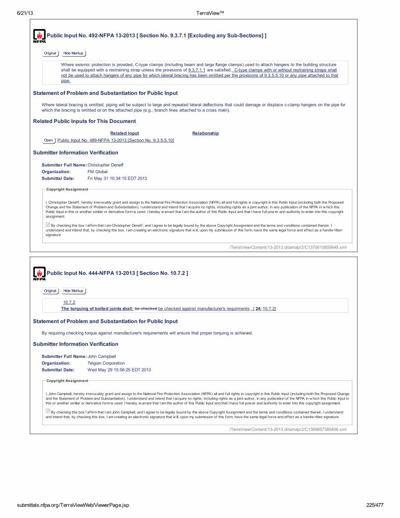
6/21/13 TerraView™
submittals.nfpa.org/TerraViewWeb/ViewerPage.jsp 225/477
Public Input No. 492-NFPA 13-2013 [ Section No. 9.3.7.1 [Excluding any Sub-Sections] ]
Original Hide Markup
Where seismic protection is provided, C-type clamps (including beam and large flange clamps) used to attach hangers to the building structureshall be equipped with a restraining strap unless the provisions of 9.3.7.1.1 are satisfied. C-type clamps with or without restraining straps shallnot be used to attach hangers of any pipe for which lateral bracing has been omitted per the provisions of 9.3.5.5.10 or any pipe attached to thatpipe.
Statement of Problem and Substantiation for Public Input
Where lateral bracing is omitted, piping will be subject to large and repeated lateral deflections that could damage or displace c-clamp hangers on the pipe for which the bracing is omitted or on the attached pipe (e.g., branch lines attached to a cross main).
Related Public Inputs for This Document
Related Input Relationship
Open Public Input No. 489-NFPA 13-2013 [Section No. 9.3.5.5.10]
Submitter Information Verification
Submitter Full Name:Christopher Deneff
Organization: FM Global
Submittal Date: Fri May 31 10:34:15 EDT 2013
Copyright Assignment
I, Christopher Deneff, hereby irrevocably grant and assign to the National Fire Protection Association (NFPA) all and full rights in copyright in this Public Input (including both the Proposed
Change and the Statement of Problem and Substantiation). I understand and intend that I acquire no rights, including rights as a joint author, in any publication of the NFPA in w hich this
Public Input in this or another similar or derivative form is used. I hereby w arrant that I am the author of this Public Input and that I have full pow er and authority to enter into this copyright
assignment.
By checking this box I aff irm that I am Christopher Deneff, and I agree to be legally bound by the above Copyright Assignment and the terms and conditions contained therein. I
understand and intend that, by checking this box, I am creating an electronic signature that w ill, upon my submission of this form, have the same legal force and effect as a handw ritten
signature
Public Input No. 444-NFPA 13-2013 [ Section No. 10.7.2 ]
Original Hide Markup
10.7.2
The torquing of bolted joints shall be checked be checked against manufacturer's requirments . [ 24: 10.7.2]
Statement of Problem and Substantiation for Public Input
By requiring checking torque against manufacturer's requirements will ensure that proper torquing is achieved.
Submitter Information Verification
Submitter Full Name:John Campbell
Organization: Telgian Corporation
Submittal Date: Wed May 29 15:56:25 EDT 2013
Copyright Assignment
I, John Campbell, hereby irrevocably grant and assign to the National Fire Protection Association (NFPA) all and full rights in copyright in this Public Input (including both the Proposed Change
and the Statement of Problem and Substantiation). I understand and intend that I acquire no rights, including rights as a joint author, in any publication of the NFPA in w hich this Public Input in
this or another similar or derivative form is used. I hereby w arrant that I am the author of this Public Input and that I have full pow er and authority to enter into this copyright assignment.
By checking this box I aff irm that I am John Campbell, and I agree to be legally bound by the above Copyright Assignment and the terms and conditions contained therein. I understand
and intend that, by checking this box, I am creating an electronic signature that w ill, upon my submission of this form, have the same legal force and effect as a handw ritten signature
/TerraView/Content/13-2013.ditamap/2/C1370010855649.xml
/TerraView/Content/13-2013.ditamap/2/C1369857385406.xml

6/21/13 TerraView™
submittals.nfpa.org/TerraViewWeb/ViewerPage.jsp 453/477
Public Input No. 26-NFPA 13-2013 [ New Section after A.9.1.4.1 ]
A.9.1.5.4 Fasteners having designs other than those covered under Sections 9.1.3, 9.1.4 and 9.1.5 are permitted when listed as part of a hangerassembly. However, this requirement is not intended to permit listing of smaller sized or a reduced number of fasteners described in Sections 9.1.3,9.1.4 and 9.1.5.
Additional Proposed Changes
File Name Description Approved
Open 13_Laverick_9-1-1-5-4.docx Cover Sheet
Statement of Problem and Substantiation for Public Input
The proposal clarifies that common fastener requirements cannot be reduced based on testing a hanger assembly. The current requirements consider fastening into materials having unknown or uncontrolled conditions such as a void or knot area of a wood beam and should not be reduced.
Submitter Information Verification
Submitter Full Name:George Laverick
Organization: UL LLC
Submittal Date: Thu Jan 24 10:53:09 EST 2013
Copyright Assignment
I, George Laverick, hereby irrevocably grant and assign to the National Fire Protection Association (NFPA) all and full rights in copyright in this Public Input (including both the Proposed
Change and the Statement of Problem and Substantiation). I understand and intend that I acquire no rights, including rights as a joint author, in any publication of the NFPA in w hich this
Public Input in this or another similar or derivative form is used. I hereby w arrant that I am the author of this Public Input and that I have full pow er and authority to enter into this copyright
assignment.
By checking this box I aff irm that I am George Laverick, and I agree to be legally bound by the above Copyright Assignment and the terms and conditions contained therein. I understand
and intend that, by checking this box, I am creating an electronic signature that w ill, upon my submission of this form, have the same legal force and effect as a handw ritten signature
Public Input No. 357-NFPA 13-2013 [ Section No. A.9.3.1 ]
Original Hide Markup
A.9.3.1
Sprinkler systems are protected against earthquake damage by means of the following:
(1) Stresses that would develop in the piping due to differential building movement are minimized through the use of flexible joints orclearances.
(2) Bracing is used to keep the piping fairly rigid when supported from a building component expected to move as a unit, such as a ceiling.
Areas known to have a potential for earthquakes have been identified in building code and insurance maps.
Displacement due to story drift is addressed in 9.3.2 through 9.3.4 .
Piping in racks needs to be treated like other sprinkler piping and protected in accordance with the proper rules. Piping to which in-racksprinklers are directly attached should be treated as branch line piping. Piping that connects branch lines in the racks should be treated asmains. The bracing, restraint, flexibility and requirements for flexible couplings are the same in the rack structures as at the ceiling.
Statement of Problem and Substantiation for Public Input
The standard needs some clarification on how to address piping in the racks. many people believe that they can ignore the protection rules because they are far from the building structure. They do not realize that the rack becomes the structure. This simple annex note should get them pointed in the right direction
Submitter Information Verification
Submitter Full Name:Roland Asp
Organization: National Fire Sprinkler Association
Affilliation: NFSA E&S Committee
Submittal Date: Wed May 22 16:52:52 EDT 2013
Copyright Assignment
I, Roland Asp, hereby irrevocably grant and assign to the National Fire Protection Association (NFPA) all and full rights in copyright in this Public Input (including both the Proposed Change
and the Statement of Problem and Substantiation). I understand and intend that I acquire no rights, including rights as a joint author, in any publication of the NFPA in w hich this Public Input in
this or another similar or derivative form is used. I hereby w arrant that I am the author of this Public Input and that I have full pow er and authority to enter into this copyright assignment.
By checking this box I aff irm that I am Roland Asp, and I agree to be legally bound by the above Copyright Assignment and the terms and conditions contained therein. I understand and
intend that, by checking this box, I am creating an electronic signature that w ill, upon my submission of this form, have the same legal force and effect as a handw ritten signature
/TerraView/Content/13-2013.ditamap/2/C1359042789367.xml
/TerraView/Content/13-2013.ditamap/2/C1369255972021.xml

6/21/13 TerraView™
submittals.nfpa.org/TerraViewWeb/ViewerPage.jsp 454/477
Public Input No. 429-NFPA 13-2013 [ Section No. A.9.3.2.4 ]
Original Hide Markup
A.9.3.2.4
See Figure A.9.3.2.4. Drops that extend into freestanding storage racks or other similar structures should be designed to accommodate ahorizontal relative displacement between the storage rack and the overhead supply piping. Free standing structures include but are not limited tofreezers, coolers, spray booths, and offices.
The horizontal relative displacement should be determined using the least value from one of the following formulas and be taken as the height ofthe top point of attachment to the storage rack above its base or the highest point of potential contact between the rack structure and the pipingabove its base, whichever is higher. The design should account for the differential movement value as determined from one of the two formulas,not both, and the lesser of the two values is acceptable. It should be determined how to account for the differential movement using flexiblecouplings or other approved means.
where:
D= differential movement between the rack and the roof [ft (m)]
H= height of the top point of attachment to the rack [ft (m)]
S 1 = one second period spectral acceleration per USGS 2010 Seismic Design Maps (see SEI/ASCE 7)
Fv= one second period site coefficient (Site Class D)
Fv is a function of S 1 and is determined as follows:
S 1 Fv
≤0.1 2.4
=0.2 2.0
=0.3 1.8
=0.4 1.6
≥0.5 1.5
Note: Use straight-line interpolation for intermediate values of S 1.
Figure A.9.3.2.4 Flexible Couplings for Drops.
Statement of Problem and Substantiation for Public Input
No currently available flexible couplings can provide the necessary displacement without the use of multiple devices, and the reference to them as a possible means of doing so should be removed from the annex material. As an example, a 20’-0” high rack would require 1’-0” of horizontal displacement. A 2” flexible coupling allows 0.16” of pipe deflection from centerline per foot of pipe when the manufacturer’s reduction for design use is considered. The number of flexible couplings required would be both excessive and impractical.
Submitter Information Verification
Submitter Full Name:Kenneth Wagoner
Organization: Parsley Consulting Engineers
Affilliation: American Fire Sprinkler Association
Submittal Date: Tue May 28 10:57:30 EDT 2013
Copyright Assignment
I, Kenneth Wagoner, hereby irrevocably grant and assign to the National Fire Protection Association (NFPA) all and full rights in copyright in this Public Input (including both the Proposed
Change and the Statement of Problem and Substantiation). I understand and intend that I acquire no rights, including rights as a joint author, in any publication of the NFPA in w hich this
Public Input in this or another similar or derivative form is used. I hereby w arrant that I am the author of this Public Input and that I have full pow er and authority to enter into this copyright
assignment.
By checking this box I aff irm that I am Kenneth Wagoner, and I agree to be legally bound by the above Copyright Assignment and the terms and conditions contained therein. I understand
and intend that, by checking this box, I am creating an electronic signature that w ill, upon my submission of this form, have the same legal force and effect as a handw ritten signature
/TerraView/Content/13-2013.ditamap/2/C1369753050720.xml

6/21/13 TerraView™
submittals.nfpa.org/TerraViewWeb/ViewerPage.jsp 455/477
Public Input No. 482-NFPA 13-2013 [ Section No. A.9.3.5 ]
Original Hide Markup
A.9.3.5
Figure A.9.3.5(a) and Figure A.9.3.5(b) are examples of forms used to aid in the preparation of bracing calculations.
Figure A.9.3.5(a) Seismic Bracing Calculation Form.
Replace these forms with revised forms attached
Figure A.9.3.5(b) Sample Seismic Bracing Calculation Form.
Additional Proposed Changes
File Name Description Approved
Open Figure_A.9.3.5_a_.pdfReplacement Figure A.9.3.5(a)

6/21/13 TerraView™
submittals.nfpa.org/TerraViewWeb/ViewerPage.jsp 456/477
Open Figure_A.9.3.5_b_.pdf Replacement Figure A.9.3.5(b)
Statement of Problem and Substantiation for Public Input
The Figures in the 2013 edition do not indicate what main size and pipe type is used when applying section 9.3.5.5.2 and they don't have a place for the Structural Attachement Listed Load Rating and Adjusted Load Rating.
Submitter Information Verification
Submitter Full Name:JOHN DEUTSCH
Organization: VFS FIRE AND SECURITY
Submittal Date: Thu May 30 15:56:00 EDT 2013
Copyright Assignment
I, JOHN DEUTSCH, hereby irrevocably grant and assign to the National Fire Protection Association (NFPA) all and full rights in copyright in this Public Input (including both the Proposed
Change and the Statement of Problem and Substantiation). I understand and intend that I acquire no rights, including rights as a joint author, in any publication of the NFPA in w hich this
Public Input in this or another similar or derivative form is used. I hereby w arrant that I am the author of this Public Input and that I have full pow er and authority to enter into this copyright
assignment.
By checking this box I aff irm that I am JOHN DEUTSCH, and I agree to be legally bound by the above Copyright Assignment and the terms and conditions contained therein. I understand
and intend that, by checking this box, I am creating an electronic signature that w ill, upon my submission of this form, have the same legal force and effect as a handw ritten signature
/TerraView/Content/13-2013.ditamap/2/C1369943760141.xml
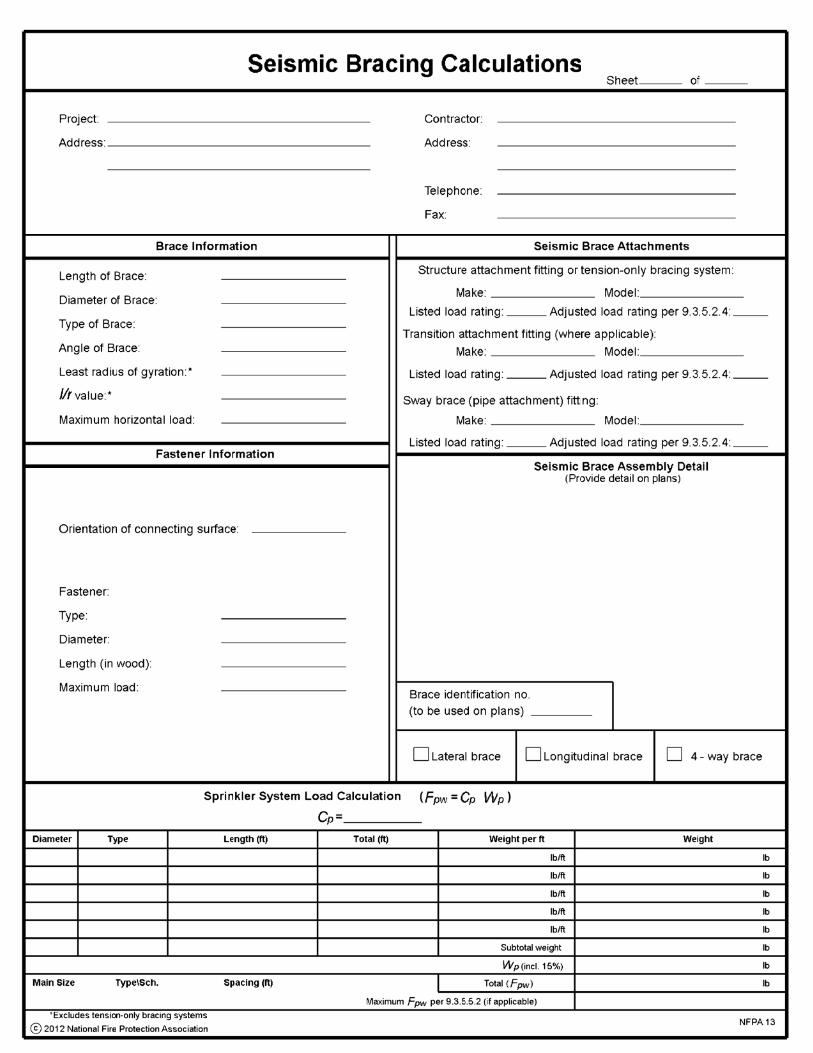


6/21/13 TerraView™
submittals.nfpa.org/TerraViewWeb/ViewerPage.jsp 457/477
Public Input No. 268-NFPA 13-2013 [ Section No. A.9.3.5.4.2 ]
Original Hide Markup
A.9.3.5.4.2
The investigation of tension-only bracing using materials, connection methods, or both, other than those described in Table 9.3.5.11.8(a) ,Table 9.3.5.11.8(b) , and Table 9.3.5.11.8(c) , should involve consideration of the following:
(1) Corrosion resistance.
(2) Prestretching to eliminate permanent construction stretch and to obtain a verifiable modulus of elasticity.
(3) Color coding or other verifiable marking of each different size cable for field verification.
(4) The capacity of all components of the brace assemblies, including the field connections, to maintain the manufacturer's minimum certifiedbreak strength.
(5) Manufacturer's published design data sheets/manual showing product design guidelines, including connection details, load calculationprocedures for sizing of braces, and the maximum recommended horizontal load-carrying capacity of the brace assemblies including theassociated fasteners as described in Figure 9.3.5.12.1 . The maximum allowable horizontal loads must not exceed the manufacturer'sminimum certified break strength of the brace assemblies, excluding fasteners, after taking a safety factor of 1.5 and then adjusting for thebrace angle.
(6) Brace product shipments accompanied by the manufacturer's certification of the minimum break strength and prestretching andinstallation instructions.
(7) The manufacturer's literature, including any special tools or precautions required to ensure proper installation.
(8) A means to prevent vertical motion due to seismic forces when required.
Table A.9.3.5.4.2 identifies some specially listed tension-only bracing systems.
Table A.9.3.5.4.2 Specially Listed Tension-Only Seismic Bracing
Materials and Dimensions Standard
Manual for Structural Application of Steel Cable s ASCE 19
Wire Rope Users Manual of the Wire Rope Technical Board ASCE 19
Mechanical Strength Requirements ASTM A
603
1023
Break ing Strength Failure Testing ASTM E 8
Statement of Problem and Substantiation for Public Input
The reference to ASTM A 603 should be replaced with ASTM A 1023, becasue ASCE 19 now contains a direct reference to ASTM A 1023 Table 9 for the steel cables used for seismic sway bracing of non-structural architecdtural, electrical and mechanical building components, rather than ASTM A 603. The reference to the Wire Rope Users Manual should be deleted, since the need for it is obviated by the direct reference to ASTM A 1023.
Submitter Information Verification
Submitter Full Name:Daniel Duggan
Organization: Fire Sprinkler Design
Affilliation: Loos & Co., Inc.
Submittal Date: Fri May 10 14:43:43 EDT 2013
Copyright Assignment
I, Daniel Duggan, hereby irrevocably grant and assign to the National Fire Protection Association (NFPA) all and full rights in copyright in this Public Input (including both the Proposed Change
and the Statement of Problem and Substantiation). I understand and intend that I acquire no rights, including rights as a joint author, in any publication of the NFPA in w hich this Public Input in
this or another similar or derivative form is used. I hereby w arrant that I am the author of this Public Input and that I have full pow er and authority to enter into this copyright assignment.
By checking this box I aff irm that I am Daniel Duggan, and I agree to be legally bound by the above Copyright Assignment and the terms and conditions contained therein. I understand
and intend that, by checking this box, I am creating an electronic signature that w ill, upon my submission of this form, have the same legal force and effect as a handw ritten signature
Public Input No. 397-NFPA 13-2013 [ Section No. A.9.3.5.9 ]
Original Hide Markup
A.9.3.5.9
Location of Sway Bracing. Two-way braces are either longitudinal or lateral, depending on their orientation with the axis of the piping. [SeeFigure A.9.3.5.9(a) , Figure A.9.3.5.9(b) , Figure A.9.3.5.9(c) , and Figure A.9.3.5.9(d) .] The simplest form of two-way brace is a piece ofsteel pipe or angle. Because the brace must act in both compression and tension, it is necessary to size the brace to prevent buckling.
An important aspect of sway bracing is its location. In Building 1 of Figure A.9.3.5.9(a) , the relatively heavy main will pull on the branch lineswhen shaking occurs. If the branch lines are held rigidly to the roof or floor above, the fittings can fracture due to the induced stresses. Inselecting brace locations, one must consider both the design load on the brace, as well as the ability of the pipe to span between bracelocations.
Bracing should be on the main as indicated at Location B. With shaking in the direction of the arrows, the light branch lines will be held at the
/TerraView/Content/13-2013.ditamap/2/C1368211423085.xml

6/21/13 TerraView™
submittals.nfpa.org/TerraViewWeb/ViewerPage.jsp 458/477
fittings. Where necessary, a lateral brace or other restraint should be installed to prevent a branch line from striking against building componentsor equipment.
A four-way brace is indicated at Location A. This keeps the riser and main lined up and also prevents the main from shifting.
In Building 1, the branch lines are flexible in a direction parallel to the main, regardless of building movement. The heavy main cannot shift underthe roof or floor, and it also steadies the branch lines. While the main is braced, the flexible couplings on the riser allow the sprinkler system tomove with the floor or roof above, relative to the floor below.
Figure A.9.3.5.9(a) Typical Earthquake Protection for Sprinkler Main Piping.
Figure A.9.3.5.9(b) , Figure A.9.3.5.9(c) , and Figure A.9.3.5.9(d) show typical locations of sway bracing.
Figure A.9.3.5.9(b) Typical Location of Bracing on Mains on Tree System.
Figure A.9.3.5.9(c) Typical Location of Bracing on Mains on Gridded System.

6/21/13 TerraView™
submittals.nfpa.org/TerraViewWeb/ViewerPage.jsp 459/477
Figure A.9.3.5.9(d) Typical Location of Bracing on Mains on Looped System.
For all threaded connections, sight holes or other means should be provided to permit indication that sufficient thread is engaged.
To properly size and space braces, it is necessary to employ the following steps:
(1) Determine the seismic coefficient, C p , using the procedures in 9.3.5.9.3 or 9 . 3.5.9.4 . This is needed by the designer to verify that
the piping can span between brace points. For the purposes of this example, assume that C p = 0.5.
(2) Based on the distance of mains from the structural members that will support the braces, choose brace shapes and sizes from Table9.3.5.11.8(a) , Table 9.3.5.11.8(b) , and Table 9.3.5.11.8(c) such that the maximum slenderness ratios, l / r , do not exceed 300. Theangle of the braces from the vertical should be at least 30 degrees and preferably 45 degrees or more.
(3) Tentatively space lateral braces at 40 ft (12 m) maximum distances along mains and tentatively space longitudinal braces at 80 ft (24 m)maximum distances along mains. Lateral braces should meet the piping at right angles, and longitudinal braces should be aligned with thepiping.
(4) Determine the total load tentatively applied to each brace in accordance with the examples shown in Figure A.9.3.5.9(e) and thefollowing:
(a) For the loads on lateral braces on cross mains, add C p times the weight of the branch to C p times the weight of the portion of
the cross main within the zone of influence of the brace. [See examples 1, 3, 6, and 7 in Figure A.9.3.5.9(e) .]
(b) For the loads on longitudinal braces on cross mains, consider only C p times the weight of the cross mains and feed mains within
the zone of influence. Branch lines need not be included. [See examples 2, 4, 5, 7, and 8 in Figure A.9.3.5.9(e) .]
(c) For the four-way brace at the riser, add the longitudinal and lateral loads within the zone of influence of the brace [see examples 2,3, and 5 in Figure A.9.3.5.9(e) ]. For the four-way bracing at the top of the riser, C p times the weight of the riser should be
assigned to both the lateral and longitudinal loads as they are separately considered.
(d) When a single brace has a combined load from both lateral and longitudinal forces (such as a lateral brace at the end of a main thatturns 90 degrees), only the lateral should be considered for comparison with the load tables in 9.3.5.5.2 .
(5) If the total expected loads are less than the maximums permitted in Table 9.3.5.11.8(a) , Table 9.3.5.11.8(b) , and Table 9.3.5.11.8(c)for the particular brace and orientation, and the maximum loads in the zone of influence of each lateral sway brace are less than themaximum values in Table 9.3.5.5.2(a) or Table 9.3.5.5.2(b) , go on to step (6). If not, add additional braces to reduce the zones ofinfluence of overloaded braces.
(6) Check that fasteners connecting the braces to structural supporting members are adequate to support the expected loads on the bracesin accordance with Figure 9.3.5.12.1 . If not, again add additional braces or additional means of support. Plates using multiple fasteners inseismic assemblies should follow the plate manufacturer guidelines regarding the applied loads.
Use the information on weights of water-filled piping contained within Table A.9.3.5.9 . The factor of 1.15 is intended to approximate theadditional weight of all the valves, fittings, and other devices attached to the system.
Figure A.9.3.5.9(e) Examples of Load Distribution to Bracing.

6/21/13 TerraView™
submittals.nfpa.org/TerraViewWeb/ViewerPage.jsp 460/477
Table A.9.3.5.9 Piping Weights for Determining Horizontal Load
Nominal Dimensions Weight of Water-Filled Pipe
in. mm lb/ft kg/m
Schedule 40 Pipe
1 25 2.05 3.05
1 1 ⁄ 4 32 2.93 4.36
1 1 ⁄ 2 40 3.61 5.37
2 50 5.13 7.63
2 1 ⁄ 2 65 7.89 11.74
3 80 10.82 16.10
3 1 ⁄ 2 90 13.48 20.06
4 100 16.40 24.41
5 125 23.47 34.93
6 150 31.69 47.16
8* 200 47.70 70.99
Schedule 10 Pipe
1 25 1.81 2.69
1 1 ⁄ 4 32 2.52 3.75
1 1 ⁄ 2 40 3.04 4.52
2 50 4.22 6.28
2 1 ⁄ 2 65 5.89 8.77
3 80 7.94 11.82
3 1 ⁄ 2 90 9.78 14.55
4 100 11.78 17.53
5 125 17.30 25.75
6 150 23.03 34.27
8 200 40.08 59.65
* Schedule 30.
Statement of Problem and Substantiation for Public Input
All we are proposing is adding "or 9.3.5.9.4" to part (1) of the procedure. This is in keeping with the rules of NFPA 13 regarding the determination of Cp.
Submitter Information Verification
Submitter Full Name:Roland Asp
Organization: National Fire Sprinkler Association
Affilliation: NFSA E&S Committee
Submittal Date: Thu May 23 16:20:41 EDT 2013
Copyright Assignment
I, Roland Asp, hereby irrevocably grant and assign to the National Fire Protection Association (NFPA) all and full rights in copyright in this Public Input (including both the Proposed Change
and the Statement of Problem and Substantiation). I understand and intend that I acquire no rights, including rights as a joint author, in any publication of the NFPA in w hich this Public Input in
this or another similar or derivative form is used. I hereby w arrant that I am the author of this Public Input and that I have full pow er and authority to enter into this copyright assignment.
By checking this box I aff irm that I am Roland Asp, and I agree to be legally bound by the above Copyright Assignment and the terms and conditions contained therein. I understand and
intend that, by checking this box, I am creating an electronic signature that w ill, upon my submission of this form, have the same legal force and effect as a handw ritten signature
/TerraView/Content/13-2013.ditamap/2/C1369340441761.xml

6/21/13 TerraView™
submittals.nfpa.org/TerraViewWeb/ViewerPage.jsp 461/477
Public Input No. 428-NFPA 13-2013 [ Section No. A.9.3.5.9.6.1 ]
Original Hide Markup
A.9.3.5.9.6.1
Where steel Schedule 10 and Schedule 40 pipe are used, the section modules modulus can be found in Table 9.1.1.7.1(b).
Statement of Problem and Substantiation for Public Input
Typographic error.
Submitter Information Verification
Submitter Full Name:Kenneth Wagoner
Organization: Parsley Consulting Engineers
Affilliation: American Fire Sprinkler Association
Submittal Date: Tue May 28 10:55:00 EDT 2013
Copyright Assignment
I, Kenneth Wagoner, hereby irrevocably grant and assign to the National Fire Protection Association (NFPA) all and full rights in copyright in this Public Input (including both the Proposed
Change and the Statement of Problem and Substantiation). I understand and intend that I acquire no rights, including rights as a joint author, in any publication of the NFPA in w hich this
Public Input in this or another similar or derivative form is used. I hereby w arrant that I am the author of this Public Input and that I have full pow er and authority to enter into this copyright
assignment.
By checking this box I aff irm that I am Kenneth Wagoner, and I agree to be legally bound by the above Copyright Assignment and the terms and conditions contained therein. I understand
and intend that, by checking this box, I am creating an electronic signature that w ill, upon my submission of this form, have the same legal force and effect as a handw ritten signature
Public Input No. 553-NFPA 13-2013 [ New Section after A.9.3.5.11 ]
A.9.3.5.11
Sway brace design and installation is critical to performance and requires attention to detail. Sway brace design parameters aredynamic and interdependent. Accordingly, seismic force is influenced by geography, brace location is impacted by system design andbrace geometry is relative to the building structure.
To enhance system durability and performance, sway brace installation shall evidence good craftsmanship in conformance to approveddrawings, correctly assembled and mounted at proper angles on a plane that corresponds to the parallel and perpendicular axis of thesystem pipe.
Additional Proposed Changes
File Name Description Approved
Open NFPAPublicInputForm_A.9.3.5.11.docx Cover Sheet
Statement of Problem and Substantiation for Public Input
AHJ’s continue to request an appendix statement regarding sway brace installation Q.C. similar to the hanger installation statement at A.9.2.
Submitter Information Verification
Submitter Full Name:Kraig Kirschner
Organization: AFCON
Submittal Date: Mon Jun 03 10:31:37 EDT 2013
Copyright Assignment
I, Kraig Kirschner, hereby irrevocably grant and assign to the National Fire Protection Association (NFPA) all and full rights in copyright in this Public Input (including both the Proposed
Change and the Statement of Problem and Substantiation). I understand and intend that I acquire no rights, including rights as a joint author, in any publication of the NFPA in w hich this
Public Input in this or another similar or derivative form is used. I hereby w arrant that I am the author of this Public Input and that I have full pow er and authority to enter into this copyright
assignment.
By checking this box I aff irm that I am Kraig Kirschner, and I agree to be legally bound by the above Copyright Assignment and the terms and conditions contained therein. I understand
and intend that, by checking this box, I am creating an electronic signature that w ill, upon my submission of this form, have the same legal force and effect as a handw ritten signature
/TerraView/Content/13-2013.ditamap/2/C1369752900667.xml
/TerraView/Content/13-2013.ditamap/2/C1370269897126.xml

6/21/13 TerraView™
submittals.nfpa.org/TerraViewWeb/ViewerPage.jsp 462/477
Public Input No. 398-NFPA 13-2013 [ New Section after A.9.3.6.6 ]
A.9.3.7.8
Concrete anchors included in current Evaluation Service Reports conforming to the requirements of acceptance criteria AC193 or AC308 as issued byICC Evaluation Service, Inc. should be considered to meet ACI 355.2, Qualification of Post-Installed Mechanical Anchors in Concrete & Commentary.
Statement of Problem and Substantiation for Public Input
The statement is taken from A.9.3.5.12.7.1. It is true for both hangers and braces using concrete anchors.
Submitter Information Verification
Submitter Full Name:Roland Asp
Organization: National Fire Sprinkler Association
Affilliation: NFSA E&S Committee
Submittal Date: Thu May 23 16:29:04 EDT 2013
Copyright Assignment
I, Roland Asp, hereby irrevocably grant and assign to the National Fire Protection Association (NFPA) all and full rights in copyright in this Public Input (including both the Proposed Change
and the Statement of Problem and Substantiation). I understand and intend that I acquire no rights, including rights as a joint author, in any publication of the NFPA in w hich this Public Input in
this or another similar or derivative form is used. I hereby w arrant that I am the author of this Public Input and that I have full pow er and authority to enter into this copyright assignment.
By checking this box I aff irm that I am Roland Asp, and I agree to be legally bound by the above Copyright Assignment and the terms and conditions contained therein. I understand and
intend that, by checking this box, I am creating an electronic signature that w ill, upon my submission of this form, have the same legal force and effect as a handw ritten signature
Public Input No. 3-NFPA 13-2013 [ Section No. A.11.3.1.1 ]
Original Hide Markup
A.11.3.1.1
In Figure A.11.3.1.1(a) , calculate the area indicated by the heavy outline and X.
The
circle indicates sprinklers.
The protection area for residential sprinklers with extended coverage areas is defined in the listing of the sprinkler as a maximum square area forpendent sprinklers or a square or rectangular area. Listing information is presented in even 2 ft (0.61 m) increments for residential sprinklers.When a sprinkler is selected for an application, its area of coverage must be equal to or greater than both the length and width of the hazardarea. For example, if the hazard to be protected is a room 14 ft 6 in. (4.3 m) wide and 20 ft 8 in. (6.2 m) long, a sprinkler that is listed to protectan area of 16 ft × 22 ft (4.9 m × 6.8 m) must be selected. The flow used in the calculations is then selected as the flow required by the listing forthe selected coverage. [See Figure A.11.3.1.1(b).]
Figure A.11.3.1.1(
a) Examples of Design Area for Dwelling Units.
/TerraView/Content/13-2013.ditamap/2/C1369340944144.xml