Embed Size (px)
Citation preview

Page 1 of 1
Technical Committee on Gaseous Fire Extinguishing Systems
M E M O R A N D U M
DATE: February 18, 2016
TO: Principal and Alternate Members of the Technical Committee on Gaseous Fire
Extinguishing Systems
FROM: Barry Chase, NFPA Staff Liaison
Office: (617) 984-7259 Email: [email protected]
SUBJECT: AGENDA – NFPA 12, 12A, and 2001 First Draft Meeting (Fall 2017)
March 17-18, 2016, Four Points by Sheraton French Quarter, New Orleans, LA
1. Call to Order – March 17, 2016, 8:00 am Central
2. Introductions and Attendance
3. Chair’s Comments and Agenda Review
4. NFPA Staff Liaison Presentation
a. NFPA Standards Development Process
b. Fall 2017 Revision Cycle Schedule
c. NFPA Resources
5. Approval of Previous Meeting Minutes
a. March 26-27, 2014 – NFPA 12, 12A, and 2001 Second Draft Meeting (San Antonio, TX)
6. NFPA 12 First Draft
a. Address Public Input (17 submittals, ATTACHED)
b. Committee Revisions
7. NFPA 12A First Draft
a. Address Public Input (7 submittals, ATTACHED)
b. Committee Revisions
8. NFPA 2001 First Draft
a. Address Public Input (38 submittals, ATTACHED)
b. Committee Revisions
9. Other Business
10. Next Meeting
Please submit requests for additional agenda items to the chair at least seven days prior to the meeting,
and notify the chair and staff liaison as soon as possible if you plan to introduce any committee revisions
at the meeting.
All NFPA Technical Committee meetings are open to the public. Please contact me for information on
attending a meeting as a guest. Read NFPA's Regulations Governing the Development of NFPA
Standards (Section 3.3.3.3) for further information.
Additional Meeting Information:
See the Meeting Notice on the Document Information Page (www.nfpa.org/12next,
www.nfpa.org/12Anext or www.nfpa.org/2001next) for meeting location details. If you have any
questions, please feel free to contact Diane Matthews, Administrator, Technical Projects, at 617-984-
7407 or by email [email protected].
C. Standards Administration
Page 1 of 111

Technical Committee on Gaseous Fire Extinguishing Systems (GFE-AAA)NFPA 12, NFPA 12A, and NFPA 2001 Second Draft Meeting (Fall 2017)
Thursday, March 17 - Friday, March 18, 2016 Four Points by Sheraton French Quarter, New Orleans, LA
Attachment #1
NFPA 12 Standard on Carbon Dioxide Extinguishing Systems
Public Input
Page 2 of 111

Public Input No. 2-NFPA 12-2015 [ Chapter 2 ]
Chapter 2 Referenced Publications
2.1 General.
The documents or portions thereof listed in this chapter are referenced within this standard and shall beconsidered part of the requirements of this document.
2.2 NFPA Publications.
National Fire Protection Association, 1 Batterymarch Park, Quincy, MA 02169-7471.
NFPA 70® , National Electrical Code®, 2014 edition.
NFPA 72® , National Fire Alarm and Signaling Code, 2013 edition.
2.3 Other Publications.
2.3.1 ANSI Publications.
American National Standards Institute, Inc., 25 West 43rd Street, 4th Floor, New York, NY 10036.
ANSI /IEEE C2, National Electrical Safety Code , 2012.ANSI Z535 Z535 .2 , Standard for Environmentaland Facility Safety Signs, 2011.
2.3.2 API Publications.
American Petroleum Institute, 1220 L Street, NW, Washington, DC 20005-4070.
API-ASME Code for Unfired Pressure Vessels for Petroleum Liquids and Gases, Pre–July 1, 1961.
2.3.3 ASME Publications.
American Society of Mechanical Engineers ASME International , Two Park Avenue, New York, NY10016-5990.
ASME B31.1, Power Piping Code , 2012 2014 .
2.3.4 ASTM Publications.
ASTM International, 100 Barr Harbor Drive, P.O. Box C 700, West Conshohocken, PA 19428-2959.
ASTM A53/A53M , Standard Specification for Pipe, Steel, Black and Hot-Dipped, Zinc-Coated, Welded andSeamless, 2012.
ASTM A106/A106M , Standard Specification for Seamless Carbon Steel Pipe for High-TemperatureService, 2011 2014 .
ASTM A120, Specification for Pipe, Steel, Black and Hot-Dipped Zinc-Coated (Galvanized) Welded andSeamless for Ordinary Uses, 1984 (withdrawn 1987 Superseded by ASTM A53/A53M ).
ASTM A182/A182M , Standard Specification for Forged or Rolled Alloy and Stainless Steel Pipe Flanges,Forged Fittings, and Valves and Parts for High-Temperature Service, 2012 2015 .
2.3.5 CGA Publications.
Compressed Gas Association, 14501 George Carter Way, Suite 103, Chantilly, VA 20151-2923.
CGA G6 G-6 .2 , Commodity Specification for Carbon Dioxide, 2011.
National Fire Protection Association Report http://submittals.nfpa.org/TerraViewWeb/ContentFetcher?commentPara...
1 of 31 1/11/2016 8:06 AM
Page 3 of 111

2.3.6 CSA Publications.
Canadian Standards Association, 5060 Spectrum Way, Mississauga CSA Group, 178 Rexdale Blvd.,Toronto , ON, L4W 5N6 Canada , Canada M9W 1R3 .
CSA C22.1, Canadian Electrical Code, 2015 .
2.3.7 IEEE Publications.
IEEE, 445 and 501 Hoes Lanes, Piscataway, NJ 08854-4141.
IEEE C2, National Electrical Safety Code (NESC), 2012.
2.3. 7 8 U.S. Government Publications.
U.S. Government Printing Government Publishing Office, Washington, DC 20402 732 North CapitolStreet, NW, Washinton, DC 20401-0001 .
Title 46, Code of Federal Regulations, Part 58.20.
Title 46, Code of Federal Regulations, Part 72.
Title 49, Code of Federal Regulations, Parts 171–190 (Department of Transportation).
Coward, H. F., and G. W. Jones, Limits of Flammability of Gases and Vapors, U.S. Bureau of Mines Bulletin503,1952.
Zabetakis, Michael G., Flammability Characteristics of Combustible Gases and Vapors, U.S. Bureau ofMines Bulletin 627, 1965.
2.3. 8 9 Other Publications.
Merriam-Webster’s Collegiate Dictionary, 11th edition, Merriam-Webster, Inc., Springfield, MA, 2003.
2.4 References for Extracts in Mandatory Sections.
NFPA 1, Fire Code , 2015 edition.
NFPA 122, Standard for Fire Prevention and Control in Metal/Nonmetal Mining and Metal MineralProcessing Facilities, 2015 edition.
NFPA 820, Standard for Fire Protection in Wastewater Treatment and Collection Facilities, 2012 edition.
Statement of Problem and Substantiation for Public Input
Referenced current SDO names, addresses, standard names, numbers, and editions.
Related Public Inputs for This Document
Related Input Relationship
Public Input No. 3-NFPA 12-2015 [Chapter H]
Submitter Information Verification
Submitter Full Name: Aaron Adamczyk
Organization: [ Not Specified ]
Street Address:
City:
State:
Zip:
Submittal Date: Sun Jul 19 16:06:06 EDT 2015
National Fire Protection Association Report http://submittals.nfpa.org/TerraViewWeb/ContentFetcher?commentPara...
2 of 31 1/11/2016 8:06 AM
Page 4 of 111

Public Input No. 23-NFPA 12-2016 [ Section No. 2.2 ]
2.2 NFPA Publications.
National Fire Protection Association, 1 Batterymarch Park, Quincy, MA 02169-7471.
NFPA 4, Standar for Integrated Fire Protection and Life Safety System Testing, 2015 edition.
NFPA 70® , National Electrical Code®, 2014 edition.
NFPA 72® , National Fire Alarm and Signaling Code, 2013 edition.
Statement of Problem and Substantiation for Public Input
Adding to support Public input #22, if accepted.
Submitter Information Verification
Submitter Full Name: Kimberly Gruner
Organization: Fike Corporation
Street Address:
City:
State:
Zip:
Submittal Date: Wed Jan 06 14:58:51 EST 2016
National Fire Protection Association Report http://submittals.nfpa.org/TerraViewWeb/ContentFetcher?commentPara...
3 of 31 1/11/2016 8:06 AM
Page 5 of 111

Public Input No. 8-NFPA 12-2015 [ Section No. 3.3.3 ]
3.3.3 Inspection.
A visible visual examination of a system or portion thereof to verify that it appears to be in operatingcondition and is free of physical damage. [820, 2012]
Statement of Problem and Substantiation for Public Input
This text is extracted from NFPA 820, but does not match what is in NFPA 820. Section 3.3.34 of NFPA 820 uses the term visual, which is more appropriate.
Submitter Information Verification
Submitter Full Name: Jim Muir
Organization: Building Safety Division, Clark County, WA
Affilliation: NFPAs Building Code Development Committee (BCDC)
Street Address:
City:
State:
Zip:
Submittal Date: Mon Nov 09 20:40:04 EST 2015
National Fire Protection Association Report http://submittals.nfpa.org/TerraViewWeb/ContentFetcher?commentPara...
4 of 31 1/11/2016 8:06 AM
Page 6 of 111

Public Input No. 9-NFPA 12-2015 [ Section No. 4.4.1.1 ]
4.4.1.1
Specifications for carbon dioxide fire-extinguishing systems shall be prepared under the supervision of aperson fully experienced and qualified in the design of carbon dioxide extinguishing systems and with theadvice approval of the authority having jurisdiction.
Statement of Problem and Substantiation for Public Input
This Public Input offers a change that would more closely relate to the traditional role of the AHJ and avoid the implication of participation in the system design by providing design advice. The term “advice” does not impart or indicate authority, and it opens the door to concerns about liability in the wake of an incident involving an extinguishing system about which an AHJ has “advised.” This is similar to a Public Input submitted to NFPA 12A, section 5.1.1.
Submitter Information Verification
Submitter Full Name: Jim Muir
Organization: Building Safety Division, Clark County, WA
Affilliation: NFPAs Building Code Development Committee (BCDC)
Street Address:
City:
State:
Zip:
Submittal Date: Mon Nov 09 20:42:31 EST 2015
National Fire Protection Association Report http://submittals.nfpa.org/TerraViewWeb/ContentFetcher?commentPara...
5 of 31 1/11/2016 8:06 AM
Page 7 of 111

Public Input No. 22-NFPA 12-2016 [ New Section after 4.4.1.2 ]
4.4.1.3
Individual Systems that are integrated with the Carbon Dioxide Extinguishing Sytem shall be identified in thespecification for plannned testing, documentation, and maintenance in accordance wtih NFPA 4 Standardfor Integrated Fire Protection and Life Safety System Testing.
Statement of Problem and Substantiation for Public Input
Many installations utilize various individual systems (Carbon Dioxide, Fire Alarm or signaling system, emergency communication system, fire doors, dampers, elevators, smoke control, HVAC, supervising station, etc.) for fire protection and life safety where each may utilize their own code, standard, or acceptance criteria. NFPA 4 is a new standard that provides requirements for testing integrated systems together so that the entire fire protection and life safety system objective is accomplished.
Submitter Information Verification
Submitter Full Name: Kimberly Gruner
Organization: Fike Corporation
Street Address:
City:
State:
Zip:
Submittal Date: Wed Jan 06 14:51:31 EST 2016
National Fire Protection Association Report http://submittals.nfpa.org/TerraViewWeb/ContentFetcher?commentPara...
6 of 31 1/11/2016 8:06 AM
Page 8 of 111

Public Input No. 20-NFPA 12-2016 [ Section No. 4.7.1.5.1.3 ]
4.7.1.5.1.3
Flanged joints downstream of stop valves or in systems with no stop valves shall be permitted to beClass 300.
4.7.1.5.1.4
Threaded unions shall, as a minimum, be equivalent to Class 2000 forged steel.
Statement of Problem and Substantiation for Public Input
Currently there are two requirements under this one section. There have been reports that installations utilizing threaded unions are following the fitting requirements in Section 4.7.1.5.1.1 when actually the unions fall under a threaded flange. Separating the requirement pertaining to threaded unions will hopefully call more attention to it and stop confusion in the field.
Submitter Information Verification
Submitter Full Name: Katherine Adrian
Organization: Tyco Fire Protection Products
Street Address:
City:
State:
Zip:
Submittal Date: Mon Jan 04 14:36:22 EST 2016
National Fire Protection Association Report http://submittals.nfpa.org/TerraViewWeb/ContentFetcher?commentPara...
7 of 31 1/11/2016 8:06 AM
Page 9 of 111

Public Input No. 21-NFPA 12-2016 [ Section No. 4.7.1.5.1.4 ]
4.7.1.5.1. 4 5
Stainless steel fittings shall be Type 304 or 316, wrought or forged in accordance with ASTM A182,threaded or socket weld, for all sizes, 1⁄8 in. (3 mm) through 4 in. (100 mm).
Statement of Problem and Substantiation for Public Input
changing section due to public input 20
Submitter Information Verification
Submitter Full Name: Katherine Adrian
Organization: Tyco Fire Suppression & Buildi
Street Address:
City:
State:
Zip:
Submittal Date: Mon Jan 04 14:43:18 EST 2016
National Fire Protection Association Report http://submittals.nfpa.org/TerraViewWeb/ContentFetcher?commentPara...
8 of 31 1/11/2016 8:06 AM
Page 10 of 111

Public Input No. 16-NFPA 12-2015 [ Section No. 4.7.2 [Excluding any Sub-Sections] ]
The piping system shall be securely supported with due allowance for agent thrust forces and thermalexpansion and contraction and shall not be subject to mechanical, chemical, or other damage.
Statement of Problem and Substantiation for Public Input
Removes unenforceable language.
Submitter Information Verification
Submitter Full Name: David Hague
Organization: Liberty Mutual Insurance
Street Address:
City:
State:
Zip:
Submittal Date: Wed Dec 23 10:09:59 EST 2015
National Fire Protection Association Report http://submittals.nfpa.org/TerraViewWeb/ContentFetcher?commentPara...
9 of 31 1/11/2016 8:06 AM
Page 11 of 111

Public Input No. 17-NFPA 12-2015 [ Section No. 4.7.2.1 ]
4.7.2.1
Where explosions are possible, the piping system shall be hung from supports that are least likely to bedisplaced.
Statement of Problem and Substantiation for Public Input
Removes unenforceable language.
Submitter Information Verification
Submitter Full Name: David Hague
Organization: Liberty Mutual Insurance
Street Address:
City:
State:
Zip:
Submittal Date: Wed Dec 23 10:12:30 EST 2015
National Fire Protection Association Report http://submittals.nfpa.org/TerraViewWeb/ContentFetcher?commentPara...
10 of 31 1/11/2016 8:06 AM
Page 12 of 111

Public Input No. 18-NFPA 12-2015 [ New Section after 4.7.5.3.2 ]
TITLE OF NEW CONTENT
Type your content here ...
4.7.6 Pipe Hangers and Supports . All pipe hangers and supports shall be in accordance with ANSI B31.1
4.7.6.1 All pipe hangers and supports shall be attached directly to the building structure.
4.7.6.2 Rigid hangers are required wherever a change in direction or elevation occurs. 4.7.6.3 On longstraight runs in excess of 20ft., every other hanger shall be rigid.
4.7.6.4 All hangers and components shall be ferrous.
4.7.6.5 All piping shall be attached to rigid hangers by means of u-bolts fastened with double nuts.
4.7.6.5.1 The pipe shall be free to move longitudinally within the u-bolt unless the piping design requires itto be anchored.
A.4.7.6.5.1 Hangers and pipe should be designed to allow longitudinal movement due to agent thrustforces and thermal expansion.
4.7.6.5.6 All pipe supports shall be designed and installed to prevent movement of supported pipe duringsystem discharge.
4.7.6.5.7 Where explosions are possible, the piping system shall be supported to prevent displacement.
4.7.6.5.8 The maximum distance between hangers shall not exceed that specified in Table 4.7.6.5.8.
4.7.6.5.9 Where required, seismic bracing shall be in accordance with NFPA 13.
Table 4.7.6.5.8 Maximum Spacing Between Supports
For Threaded or Welded Pipe
Nominal Pipe Size Maximum Span
in. mm ft m
1/4 6 5 1.5
1/2 15 5 1.5
3/4 20 6 1.8
1 25 7 2.1
1 1/4 32 8 2.4
1 1/2 40 9 2.7
2 50 10 3.0
2 1/2 65 11 3.4
3 80 12 3.7
4 100 14 4.3
5 125 16 4.9
6 150 17 5.2
8 200 19 5.8
National Fire Protection Association Report http://submittals.nfpa.org/TerraViewWeb/ContentFetcher?commentPara...
11 of 31 1/11/2016 8:06 AM
Page 13 of 111

Statement of Problem and Substantiation for Public Input
Presently there is little guidance on the proper support of CO2 system piping (low pressure systems only – see Section 4.7.2) and no guidance for support of high pressure systems at all. Due to the potential for pipe movement and dislodgement due to agent forces and thermal expansion/contraction, there is a need to specify rigid pipe supports at critical points of the system and dead weight support for the remainder of the system piping. There are no requirements presently for seismic bracing of system piping.
Submitter Information Verification
Submitter Full Name: David Hague
Organization: Liberty Mutual Insurance
Street Address:
City:
State:
Zip:
Submittal Date: Wed Dec 23 10:13:59 EST 2015
National Fire Protection Association Report http://submittals.nfpa.org/TerraViewWeb/ContentFetcher?commentPara...
12 of 31 1/11/2016 8:06 AM
Page 14 of 111

Public Input No. 11-NFPA 12-2015 [ Section No. 5.3.2.2 ]
National Fire Protection Association Report http://submittals.nfpa.org/TerraViewWeb/ContentFetcher?commentPara...
13 of 31 1/11/2016 8:06 AM
Page 15 of 111

5.3.2.2 *
National Fire Protection Association Report http://submittals.nfpa.org/TerraViewWeb/ContentFetcher?commentPara...
14 of 31 1/11/2016 8:06 AM
Page 16 of 111

Table 5.3.2.2 shall be used to determine the minimum carbon dioxide concentrations for the liquids andgases shown in the table.
In Table 5.3.2.2 revise as follows:
(1) Revise “Higher paraffin” line in Table 5.3.2.2 by replacing “Higher paraffin hydrocarbons C n H 2m2m-5” with “Higher paraffin hydrocarbons, C n H 2n 2 , n ≥ 5”
(2) Delete “Hexane” line.
Table 5.3.2.2 Minimum Carbon Dioxide Concentrations for Extinguishment
Material
Theoretical
Minimum CO 2
Concentration
(%)
Minimum
Design CO 2
Concentration
(%)
Acetylene 55 66
Acetone 27* 34
Aviation gas grades
115/14530 36
Benzol, benzene 31 37
Butadiene 34 41
Butane 28 34
Butane-I 31 37
Carbon disulfide 60 72
Carbon monoxide 53 64
Coal or natural gas 31* 37
Cyclopropane 31 37
Diethyl ether 33 40
Dimethyl ether 33 40
Dowtherm 38* 46
Ethane 33 40
Ethyl alcohol 36 43
Ethyl ether 38* 46
Ethylene 41 49
Ethylene dichloride 21 34
Ethylene oxide 44 53
Gasoline 28 34
Hexane 29 35
Higher paraffin
hydrocarbons C n H 2m
+
2m - 5 28 34
Hydrogen 62 75
Hydrogen sulfide 30 36
Isobutane 30* 36
Isobutylene 26 34
Isobutyl formate 26 34
JP-4 30 36
National Fire Protection Association Report http://submittals.nfpa.org/TerraViewWeb/ContentFetcher?commentPara...
15 of 31 1/11/2016 8:06 AM
Page 17 of 111

Kerosene 28 34
Methane 25 34
Methyl acetate 29 35
Methyl alcohol 33 40
Methyl butene-I 30 36
Methyl ethyl ketone 33 40
Methyl formate 32 39
Pentane 29 35
Propane 30 36
Propylene 30 36
Quench, lube oils 28 34
Note: The theoretical minimum extinguishing concentrations in air for the materials in the table wereobtained from a compilation of Bureau of Mines, Bulletins 503 and 627.
*Calculated from accepted residual oxygen values.
Additional Proposed Changes
File Name Description Approved
NFPA_12_Table_5.3.2.2.docx Proposed revisions to Table 5.3.2.2
Statement of Problem and Substantiation for Public Input
Substantiation: 1. The intended “Higher paraffin” text is from the caption of Figure 35 of U.S. Bureau of Mines Bulletin 627. 2. The “Higher paraffin” line, with n = 6 (hexane), has a column #2 value = 28 % (and MDC = 34 %), while directly above is “Hexane” with a column #2 value = 29 % (and MDC = 35 %). Thus, the “Hexane” line and the “Higher paraffin” line are in conflict. Close examination of the hexane flammability data in both U.S. Bureau of Mines Bulletins 503 and 627 clearly indicates that the 28 % for hexane “Minimum Theoretical Concentration” is correct.
Submitter Information Verification
Submitter Full Name: Joseph Senecal
Organization: Kidde-Fenwal, Inc.
Street Address:
City:
State:
Zip:
Submittal Date: Wed Dec 09 08:03:11 EST 2015
National Fire Protection Association Report http://submittals.nfpa.org/TerraViewWeb/ContentFetcher?commentPara...
16 of 31 1/11/2016 8:06 AM
Page 18 of 111

NFPA 12, Table 5.3.2.2 Proposal:
1. Revise “Higher paraffin” line in Table 5.3.2.2 by replacing “Higher paraffin hydrocarbons CnH2m + 2m‐5” with “Higher paraffin hydrocarbons, CnH2n+2, n ≥ 5”
2. Delete “Hexane” line.
Substantiation:
1. The intended “Higher paraffin” text is from the caption of Figure 35 of U.S. Bureau of Mines Bulletin 627.
2. The “Higher paraffin” line, with n = 6 (hexane), has a column #2 value = 28 % (and MDC = 34 %), while directly above is “Hexane” with a column #2 value = 29 % (and MDC = 35 %). Thus, the “Hexane” line and the “Higher paraffin” line are in conflict. Close examination of the hexane flammability data in both U.S. Bureau of Mines Bulletins 503 and 627 clearly indicates that the 28 % for hexane “Minimum Theoretical Concentration” is correct.
Page 19 of 111
Public Input No. 12-NFPA 12-2015 [ Section No. 5.5.2.1 ]
5.5.2.1 *
5.5.2.1* For surface fires, the design concentration shall be achieved within
1 minute1 minute from start of liquid discharge.
5.5.2.1.1 The duration of pre-liquid vapor discharge shall not exceed 60 s.
Statement of Problem and Substantiation for Public Input
Substantiation: There is some ambiguity as to what is meant by “start of discharge.” Some liquid CO2 is vaporized in the pipe system. The duration of the pre-liquid vapor discharge can vary widely. The portion of discharge that is most effective for firefighting purposes is the liquid discharge. The proposal acknowledges the variable-duration pre-liquid vapor discharge, and emphasizes that the design concentration is to be achieved within 60 s of the onset of liquid discharge. Both the duration of pre-liquid vapor discharge and liquid discharge are calculable. The proposal harmonizes NFPA 12 with similar language in ISO 6183.
Submitter Information Verification
Submitter Full Name: Joseph Senecal
Organization: Kidde-Fenwal, Inc.
Street Address:
City:
State:
Zip:
Submittal Date: Wed Dec 09 08:07:59 EST 2015
National Fire Protection Association Report http://submittals.nfpa.org/TerraViewWeb/ContentFetcher?commentPara...
17 of 31 1/11/2016 8:06 AM
Page 20 of 111

Public Input No. 14-NFPA 12-2015 [ Section No. 5.5.2.3 ]
5.5.2.3
For deep-seated fires, the design concentration shall be achieved within 7 minutes , but the rate of thestart of liquid discharge .
5.5.2.3.1 Notwithstanding the requirements of 5.5.2.3, the rate liquid discharge shall be not less than thatrequired to develop a carbon dioxide concentration of 30 percent in 2 minutes 30 percent within 2minutes of the start of liquid discharge .
Statement of Problem and Substantiation for Public Input
1. The requirements of the current 5.5.2.3 contains two separate requirements that need to be separated;2. The duration of pre-liquid vapor discharge can be lengthy, tens of seconds, and that portion of the discharge raises CO2 concentration relatively slowly. The onset of the liquid portion of CO2 discharge begins the rapid rise in CO2 concentration and should be the starting point for development of the required concentrations.
Submitter Information Verification
Submitter Full Name: Joseph Senecal
Organization: Kidde-Fenwal, Inc.
Street Address:
City:
State:
Zip:
Submittal Date: Wed Dec 09 10:15:45 EST 2015
National Fire Protection Association Report http://submittals.nfpa.org/TerraViewWeb/ContentFetcher?commentPara...
18 of 31 1/11/2016 8:06 AM
Page 21 of 111

Public Input No. 19-NFPA 12-2015 [ Section No. A.4.7.2 ]
A.4.7.2
ASME B31.1 should be consulted for guidance on this matter.
Statement of Problem and Substantiation for Public Input
Added mandatory reference to ANSI B31.1 in new proposed section 4.7.6 "Pipe Hangers and Supports".
Submitter Information Verification
Submitter Full Name: David Hague
Organization: Liberty Mutual Insurance
Street Address:
City:
State:
Zip:
Submittal Date: Wed Dec 23 10:18:43 EST 2015
National Fire Protection Association Report http://submittals.nfpa.org/TerraViewWeb/ContentFetcher?commentPara...
19 of 31 1/11/2016 8:06 AM
Page 22 of 111

Public Input No. 13-NFPA 12-2015 [ Section No. A.5.5.2.1 ]
A.5.5.2.1
Normally Generally , the measured discharge time effective start of discharge, for fire extinguishingpurposes, is considered to be the time when the measuring device starts to record the presence ofcarbon dioxide until the design concentration is achieved occur when liquid discharge begins .
Statement of Problem and Substantiation for Public Input
The criterion of “…when the measuring device starts to record the presence of carbon dioxide…” is subject to wide variation and interpretation. 1. A measuring device may be slow to respond to the presence of CO2 gas; 2. It may use a long sample tube with substantial transit time to the measuring sensor; 3. The sensor may be placed anywhere in a protected space; 4. A sensor may respond to low concentrations of CO2 during the slow initial discharge of CO2 vapor that is created in the pipe system (the duration of “initial vapor time” can vary from less than 1 s to 30 s, or more, depending on the type of CO2 supply, high-pressure or low-pressure, and the length and mass of the pipe system). 5. Where initial vapor time is long, say 20 s, and where the initial presence of CO2 gas is detected promptly, the current language suggests to the AHJ that the liquid discharge time is to be at most 60 s – 20 s = 40 s. This would impose flow limit challenges requiring larger nozzles, and, in some cases, larger diameter pipe systems. 6. The parallel ISO CO2 systems standard, ISO 6183 / 7.7.1 Discharge time, requires, in total flood applications, a maximum liquid discharge time of 60 s and up to 60 s of “pre-liquid vapour flow time” for a total pre-liquid plus liquid discharge time of up to 120 s.
Submitter Information Verification
Submitter Full Name: Joseph Senecal
Organization: Kidde-Fenwal, Inc.
Street Address:
City:
State:
Zip:
Submittal Date: Wed Dec 09 08:10:47 EST 2015
National Fire Protection Association Report http://submittals.nfpa.org/TerraViewWeb/ContentFetcher?commentPara...
20 of 31 1/11/2016 8:06 AM
Page 23 of 111
Public Input No. 15-NFPA 12-2015 [ Section No. C.1 ]
National Fire Protection Association Report http://submittals.nfpa.org/TerraViewWeb/ContentFetcher?commentPara...
21 of 31 1/11/2016 8:06 AM
Page 24 of 111

C.1
National Fire Protection Association Report http://submittals.nfpa.org/TerraViewWeb/ContentFetcher?commentPara...
22 of 31 1/11/2016 8:06 AM
Page 25 of 111

Computing pipe sizes for carbon dioxide systems is complicated by the fact that the pressure drop isnonlinear with respect to the pipeline. Carbon dioxide leaves the storage vessel as a liquid at saturationpressure. As the pressure drops due to pipeline friction, the liquid boils and produces a mixture of liquid andvapor. Consequently, the volume of the flowing mixture increases and the velocity of flow must alsoincrease. Thus, the pressure drop per unit length of pipe is greater near the end of the pipeline than it is atthe beginning.
Pressure drop information for designing piping systems can best be obtained from curves of pressureversus equivalent length for various flow rates and pipe sizes. Such curves can be plotted using thetheoretical equation given in 4.7.5.1. The Y and Z factors in the equation in that paragraph depend onstorage pressure and line pressure. In the following equations, Z is a dimensionless ratio, and the Y factorhas units of pressure times density and will therefore change the system of units. The Y and Z factors canbe evaluated as follows:
[C.1a]
where:
P = pressure at end of pipeline [psi (kPa)]
P 1 = storage pressure [psi (kPa)]
ρ = density at pressure P [lb/ft3 (kg/m3)]
ρ 1 = density at pressure P 1 [lb/ft3 (kg/m3)]
ln = natural logarithm
The storage pressure is an important factor in carbon dioxide flow. In low-pressure storage, the startingpressure in the storage vessel will recede to a lower level, depending on whether all or only part of thesupply is discharged. Because of this, the average pressure during discharge will be about 285 psi(1965 kPa). The flow equation is based on absolute pressure; therefore, 300 psi (2068 kPa) is used forcalculations involving low-pressure systems.
In high-pressure systems, the storage pressure depends on the ambient temperature. Normal ambienttemperature is assumed to be 70°F (21°C). For this condition, the average pressure in the cylinder duringdischarge of the liquid portion will be about 750 psi (5171 kPa). This pressure has therefore been selectedfor calculations involving high-pressure systems.
Using the base pressures of 300 psi (2068 kPa) and 750 psi (5171 kPa), values have been determined forthe Y and Z factors in the flow equation. These values are listed in Table C.1(a) and Table C.1(b) .
Table C.1(a) Values of Y and Z for 300 psi Initial Storage Pressure
Pressure
(psi) Z
Y
0 1 2 3 4 5 6 7 8 9
300 0.000 0 0 0 0 0 0 0 0 0 0
290 0.135 596 540 483 426 367 308 248 187 126 63
280 0.264 1119 1070 1020 969 918 866 814 760 706 652
270 0.387 1580 1536 1492 1448 1402 1357 1310 1263 1216 1168
260 0.505 1989 1950 1911 1871 1831 1790 1749 1708 1666 1623
250 0.620 2352 2318 2283 2248 2212 2176 2139 2102 2065 2027
240 0.732 2677 2646 2615 2583 2552 2519 2487 2454 2420 2386
230 0.841 2968 2940 2912 2884 2855 2826 2797 2768 2738 2708
220 0.950 3228 3204 3179 3153 3128 3102 3075 3049 3022 2995
210 1.057 3462 3440 3418 3395 3372 3349 3325 3301 3277 3253
National Fire Protection Association Report http://submittals.nfpa.org/TerraViewWeb/ContentFetcher?commentPara...
23 of 31 1/11/2016 8:06 AM
Page 26 of 111

Pressure
(psi) Z
Y
0 1 2 3 4 5 6 7 8 9
200 1.165 3673 3653 3632 3612 3591 3570 3549 3528 3506 3485
190 1.274 3861 3843 3825 3807 3788 3769 3750 3731 3712 3692
180 1.384 4030 4014 3998 3981 3965 3948 3931 3914 3896 3879
170 1.497 4181 4167 4152 4138 4123 4108 4093 4077 4062 4046
160 1.612 4316 4303 4291 4277 4264 4251 4237 4223 4210 4196
150 1.731 4436 4425 4413 4402 4390 4378 4366 4354 4341 4329
Table C.1(b) Values of Y and Z for 750 psi Initial Storage Pressure
Y
Pressure
(psi) Z 0 1 2 3 4 5 6 7 8 9
750 0.000 0 0 0 0 0 0 0 0 0 0
740 0.038 497 448 399 350 300 251 201 151 101 51
730 0.075 975 928 881 833 786 738 690 642 594 545
720 0.110 1436 1391 1345 1299 1254 1208 1161 1115 1068 1022
710 0.143 1882 1838 1794 1750 1706 1661 1616 1572 1527 1481
700 0.174 2314 2271 2229 2186 2143 2100 2057 2013 1970 1926
690 0.205 2733 2691 2650 2608 2567 2525 2483 2441 2399 2357
680 0.235 3139 3099 3059 3018 2978 2937 2897 2856 2815 2774
670 0.265 3533 3494 3455 3416 3377 3338 3298 3259 3219 3179
660 0.296 3916 3878 3840 3802 3764 3726 3688 3649 3611 3572
650 0.327 4286 4250 4213 4176 4139 4102 4065 4028 3991 3953
640 0.360 4645 4610 4575 4539 4503 4467 4431 4395 4359 4323
630 0.393 4993 4959 4924 4890 4855 4821 4786 4751 4716 4681
620 0.427 5329 5296 5263 5229 5196 5162 5129 5095 5061 5027
610 0.462 5653 5621 5589 5557 5525 5493 5460 5427 5395 5362
600 0.498 5967 5936 5905 5874 5843 5811 5780 5749 5717 5685
590 0.535 6268 6239 6209 6179 6149 6119 6089 6058 6028 5997
580 0.572 6560 6531 6502 6473 6444 6415 6386 6357 6328 6298
570 0.609 6840 6812 6785 6757 6729 6701 6673 6645 6616 6588
560 0.646 7110 7084 7057 7030 7003 6976 6949 6922 6895 6868
550 0.683 7371 7345 7320 7294 7268 7242 7216 7190 7163 7137
540 0.719 7622 7597 7572 7548 7523 7498 7472 7447 7422 7396
530 0.756 7864 7840 7816 7792 7768 7744 7720 7696 7671 7647
520 0.792 8098 8075 8052 8028 8005 7982 7958 7935 7911 7888
510 0.827 8323 8301 8278 8256 8234 8211 8189 8166 8143 8120
500 0.863 8540 8519 8497 8476 8454 8433 8411 8389 8367 8345
490 0.898 8750 8730 8709 8688 8667 8646 8625 8604 8583 8562
480 0.933 8953 8933 8913 8893 8873 8852 8832 8812 8791 8771
470 0.967 9149 9129 9110 9091 9071 9052 9032 9012 8993 8973
460 1.002 9338 9319 9301 9282 9263 9244 9225 9206 9187 9168
450 1.038 9520 9502 9484 9466 9448 9430 9412 9393 9375 9356
440 1.073 9697 9680 9662 9644 9627 9609 9592 9574 9556 9538
430 1.109 9866 9850 9833 9816 9799 9782 9765 9748 9731 9714
National Fire Protection Association Report http://submittals.nfpa.org/TerraViewWeb/ContentFetcher?commentPara...
24 of 31 1/11/2016 8:06 AM
Page 27 of 111

Y
Pressure
(psi) Z 0 1 2 3 4 5 6 7 8 9
420 1.146 10030 10014 9998 9982 9966 9949 9933 9916 9900 9883
410 1.184 10188 10173 10157 10141 10126 10110 10094 10078 10062 10046
400 1.222 10340 10325 10310 10295 10280 10265 10250 10234 10219 10204
390 1.262 10486 10472 10458 10443 10429 10414 10399 10385 10370 10355
380 1.302 10627 10613 10599 10585 10571 10557 10543 10529 10515 10501
370 1.344 10762 10749 10735 10722 10708 10695 10681 10668 10654 10641
360 1.386 10891 10878 10866 10853 10840 10827 10814 10801 10788 10775
350 1.429 11015 11003 10991 10978 10966 10954 10941 10929 10916 10904
340 1.473 11134 11122 11110 11099 11087 11075 11063 11051 11039 11027
330 1.518 11247 11236 11225 11214 11202 11191 11180 11168 11157 11145
320 1.564 11356 11345 11334 11323 11313 11302 11291 11280 11269 11258
310 1.610 11459 11449 11439 11428 11418 11408 11398 11387 11377 11366
300 1.657 11558 11548 11539 11529 11519 11509 11499 11489 11479 11469
For practical application, it is desirable to plot curves for each pipe size that can be used. However, the flowequation can be rearranged as shown in the following equation:
[C.1b]
Thus, by plotting values of L/D 1.25 and Q/D 2, it is possible to use one family of curves for any pipe size.Figure C.1(a) gives flow information for 0°F (−18°C) storage temperature on this basis. Figure C.1(b) givessimilar information for high-pressure storage at 70°F (21°C). For an inside pipe diameter of exactly 1 in., D2 and D 1.25 reduce to unity and cancel out. For other pipe sizes, it is necessary to convert the flow rateand equivalent length by dividing or multiplying by these factors. Table C.1(c) gives values for D.
Figure C.1(a) Pressure Drop in Pipeline for 300 psi (2068 kPa) Storage Pressure.
Figure C.1(b) Pressure Drop in Pipeline for 750 psi (5171 kPa) Storage Pressure.
National Fire Protection Association Report http://submittals.nfpa.org/TerraViewWeb/ContentFetcher?commentPara...
25 of 31 1/11/2016 8:06 AM
Page 28 of 111

Table C.1(c) Values of D 1.25 and D 2 for Various Pipe Sizes
Pipe Size
and Type
Inside Diameter
(in.) D 1.25 D 2
1 ⁄ 2 Std. 0.622 0.5521 0.3869
1 ⁄ 4 Std. 0.824 0.785 0.679
1 Std. 1.049 1.0615 1.100
1 XH 0.957 0.9465 0.9158
1 1 ⁄ 4 Std. 1.380 1.496 1.904
1 1 ⁄ 4 XH 1.278 1.359 1.633
1 1 ⁄ 2 Std. 1.610 1.813 2.592
1 1 ⁄ 2 XH 1.500 1.660 2.250
2 Std. 2.067 2.475 4.272
2 XH 1.939 2.288 3.760
2 1 ⁄ 2 Std. 2.469 3.09 6.096
2 1 ⁄ 2 XH 2.323 2.865 5.396
3 Std. 3.068 4.06 9.413
3 XH 2.900 3.79 8.410
4 Std. 4.026 5.71 16.21
4 XH 3.826 5.34 14.64
5 Std. 5.047 7.54 25.47
5 XH 4.813 7.14 23.16
6 Std. 6.065 9.50 36.78
6 XH 5.761 8.92 33.19
These curves can be used for designing systems or for checking possible flow rates. For example, assumethe problem is to determine the terminal pressure for a low-pressure system consisting of a single 2 in.Schedule 40 pipeline with an equivalent length of 500 ft and a flow rate of 1000 lb/min. The flow rate andthe equivalent length must be converted to terms of Figure C.1(a) as follows:
Revise equations C.1c
From: Q/D 2 = 1000/4.28 = 234 lb/min-D 2 To: Q/D 2 = 1000/4.28 = 234 lb/min-in 2
From: L/D 1.25 = 500/2.48 = 201 ft-D 1.25 To: L/D 1.25 = 500/2.48 = 201 ft-in 1.25
National Fire Protection Association Report http://submittals.nfpa.org/TerraViewWeb/ContentFetcher?commentPara...
26 of 31 1/11/2016 8:06 AM
Page 29 of 111

[C.1c]
From Figure C.1(a), the terminal pressure is found to be about 228 psi at the point where the interpolatedflow rate of 234 lb/min intersects the equivalent length scale at 201 ft.
If this line terminates in a single nozzle, the equivalent orifice area must be matched to the terminalpressure in order to control the flow rate at the desired level of 1000 lb/min. Referring to Table 4.7.5.2.1, it
will be noted that the discharge rate will be 1410 lb/min·in.2 of equivalent orifice area when the orificepressure is 230 psi. The required equivalent orifice area of the nozzle is thus equal to the total flow ratedivided by the rate per square inch, as shown in the following equation:
[C.1d]
From a practical viewpoint, the designer would select a standard nozzle having an equivalent area nearestto the computed area. If the orifice area happened to be a little larger, the actual flow rate would be slightlyhigher and the terminal pressure would be somewhat lower than the estimated 228 psi (1572 kPa).
If, in the previous example, instead of terminating with one large nozzle, the pipeline branched into twosmaller pipelines, it would be necessary to determine the pressure at the end of each branch line. Toillustrate this procedure, assume that the branch lines are equal and consist of 1 1⁄2 in. Schedule 40 pipewith equivalent lengths of 200 ft (61 m) and that the flow in each branch line is to be 500 lb/min(227 kg/min). Converting to terms used in Figure C.1(a), the following equations result:
Revise equations C.1e
From: Q/D 2 = 500/2.592 = 193 lb/min-D 2 To: Q/D 2 = 500/2.592 = 193 lb/min-in 2
From: L/D 1.25 = 200/1.813 = 110 ft-D 1.25 To: L/D 1.25 = 200/1.813 = 110 ft/in 1.25
[C.1e]
From Figure C.1(a), the starting pressure of 228 psi (1572 kPa) (terminal pressure of main line) intersectsthe flow rate line [193 lb/min (87.6 kg/min)] at an equivalent length of about 300 ft (91.4 m). In other words,if the branch line started at the storage vessel, the liquid carbon dioxide would have to flow through 300 ft(91.4 m) of pipeline before the pressure dropped to 228 psi (1572 kPa). This length thus becomes thestarting point for the equivalent length of the branch line. The terminal pressure of the branch line is thenfound to be 165 psi (1138 kPa) at the point where the 193 lb/min (87.6 kg/min) flow rate line intersects thetotal equivalent length line of 410 ft (125 m), or 300 ft + 110 ft (91 m + 34 m). With this new terminalpressure [165 psi (1138 kPa)] and flow rate [500 lb/min (227 kg/min)], the required equivalent nozzle area
at the end of each branch line will be approximately 0.567 in.2 (366 mm2). This is about the same as thesingle large nozzle example, except that the discharge rate is cut in half due to the reduced pressure.
The design of the piping distribution system is based on the flow rate desired at each nozzle. This in turndetermines the required flow rate in the branch lines and the main pipeline. From practical experience, it ispossible to estimate the approximate pipe sizes required. The pressure at each nozzle can be determinedfrom suitable flow curves. The nozzle orifice sizes are then selected on the basis of nozzle pressure fromthe data given in 4.7.5.2.
In high-pressure systems, the main header is supplied by a number of separate cylinders. The total flow isthus divided by the number of cylinders to obtain the flow rate from each cylinder. The flow capacity of thecylinder valve and the connector to the header vary with each manufacturer, depending on design and size.For any particular valve, dip tube, and connector assembly, the equivalent length can be determined interms of feet of standard pipe size. With this information, the flow equation can be used to prepare a curveof flow rate versus pressure drop. This curve provides a convenient method of determining header pressure
National Fire Protection Association Report http://submittals.nfpa.org/TerraViewWeb/ContentFetcher?commentPara...
27 of 31 1/11/2016 8:06 AM
Page 30 of 111

for a specific valve and connector combination.
Table C.1(d) and Table C.1(e) list the equivalent lengths of pipe fittings for determining the equivalentlength of piping systems. Table C.1(d) is for threaded joints, and Table C.1(e) is for welded joints. Bothtables were computed for Schedule 40 pipe sizes; however, for all practical purposes, the same figures canalso be used for Schedule 80 pipe sizes.
Table C.1(d) Equivalent Lengths in Feet of Threaded Pipe Fitting
Pipe
Size(in.)
Elbow Std. 45Degrees
Elbow Std. 90Degrees
Elbow
90 Degrees Long Radiusand Tee Thru Flow
Tee
SideUnion Coupling or
Gate Valve
3 ⁄ 8 0.6 1.3 0.8 2.7 0.3
1 ⁄ 2 0.8 1.7 1.0 3.4 0.4
3 ⁄ 4 1.0 2.2 1.4 4.5 0.5
1 1.3 2.8 1.8 5.7 0.6
1 1 ⁄ 4 1.7 3.7 2.3 7.5 0.8
1 1 ⁄ 2 2.0 4.3 2.7 8.7 0.9
2 2.6 5.5 3.5 11.2 1.2
2 1 ⁄ 2 3.1 6.6 4.1 13.4 1.4
3 3.8 8.2 5.1 16.6 1.8
4 5.0 10.7 6.7 21.8 2.4
5 6.3 13.4 8.4 27.4 3.0
6 7.6 16.2 10.1 32.8 3.5
For SI units, 1 ft = 0.3048 m.
Table C.1(e) Equivalent Lengths in Feet of Welded Pipe Fitting
Pipe
Size(in.)
Elbow Std. 45Degrees
Elbow Std. 90Degrees
Elbow
90 Degrees Long Radius andTee Thru Flow
Tee
SideGate
Valve
3 ⁄ 8 0.2 0.7 0.5 1.6 0.3
1 ⁄ 2 0.3 0.8 0.7 2.1 0.4
3 ⁄ 4 0.4 1.1 0.9 2.8 0.5
1 0.5 1.4 1.1 3.5 0.6
1 1 ⁄ 4 0.7 1.8 1.5 4.6 0.8
1 1 ⁄ 2 0.8 2.1 1.7 5.4 0.9
2 1.0 2.8 2.2 6.9 1.2
2 1 ⁄ 2 1.2 3.3 2.7 8.2 1.4
3 1.8 4.1 3.3 10.2 1.8
4 2.0 5.4 4.4 13.4 2.4
5 2.5 6.7 5.5 16.8 3.0
6 3.0 8.1 6.6 20.2 3.5
For SI units, 1 ft = 0.3048 m.
For nominal changes in elevation of piping, the change in head pressure is negligible. However, if there is asubstantial change in elevation, this factor should be taken into account. The head pressure correction perfoot of elevation depends on the average line pressure where the elevation takes place because the densitychanges with pressure. Correction factors are given in Table C.1(f) and Table C.1(g) for low-pressure andhigh-pressure systems, respectively. The correction is subtracted from the terminal pressure when the flow
National Fire Protection Association Report http://submittals.nfpa.org/TerraViewWeb/ContentFetcher?commentPara...
28 of 31 1/11/2016 8:06 AM
Page 31 of 111

is upward and is added to the terminal pressure when the flow is downward.
Table C.1(f) Elevation Correction Factors for Low-Pressure System
Average Line Pressure Elevation Correction
psi kPa psi/ft kPa/m
300 2068 0.443 10.00
280 1930 0.343 7.76
260 1792 0.265 5.99
240 1655 0.207 4.68
220 1517 0.167 3.78
200 1379 0.134 3.03
180 1241 0.107 2.42
160 1103 0.085 1.92
140 965 0.067 1.52
Table C.1(g) Elevation Correction Factors for High-Pressure System
Average Line Pressure Elevation Correction
psi kPa psi/ft kPa/m
750 5171 0.352 7.96
700 4826 0.300 6.79
650 4482 0.255 5.77
600 4137 0.215 4.86
550 3792 0.177 4.00
500 3447 0.150 3.39
450 3103 0.125 2.83
400 2758 0.105 2.38
350 2413 0.085 1.92
300 2068 0.070 1.58
Statement of Problem and Substantiation for Public Input
The original equations incorrectly uses “D2” (pipe diameter) in the units rather than “in” (inch), which is the correct unit of pipe diameter.
Submitter Information Verification
Submitter Full Name: Joseph Senecal
Organization: Kidde-Fenwal, Inc.
Street Address:
City:
State:
Zip:
Submittal Date: Wed Dec 09 10:25:14 EST 2015
National Fire Protection Association Report http://submittals.nfpa.org/TerraViewWeb/ContentFetcher?commentPara...
29 of 31 1/11/2016 8:06 AM
Page 32 of 111

Public Input No. 3-NFPA 12-2015 [ Chapter H ]
Annex H Informational References
H.1 Referenced Publications.
The documents or portions thereof listed in this annex are referenced within the informational sections ofthis standard and are not part of the requirements of this document unless also listed in Chapter 2 for otherreasons.
H.1.1 NFPA Publications.
National Fire Protection Association, 1 Batterymarch Park, Quincy, MA 02169-7471.
NFPA 10, Standard for Portable Fire Extinguishers, 2013 edition.
NFPA 69, Standard on Explosion Prevention Systems, 2014 edition.
NFPA 72 ®, National Fire Alarm and Signaling Code, 2013 edition.
NFPA 77, Recommended Practice on Static Electricity, 2014 edition.
NFPA 96, Standard for Ventilation Control and Fire Protection of Commercial Cooking Operations, 2014edition.
NFPA 101 ®, Life Safety Code ®, 2015 edition.
H.1.2 Other Publications.
H.1.2.1 ASME Publications.
American Society of Mechanical Engineers ASME International , Two Park Avenue, New York, NY10016-5990.
ASME B31.1, Power Piping Code , 2012 2014 .
H.1.2.2 ASTM Publications.
ASTM International, 100 Barr Harbor Drive, P.O. Box C 700, West Conshohocken, PA 19428-2959.
ASTM SI10, American National Standard for Metric Practice, 2010.
H.1.2.3 DHHS Publications.
Department of Health and Human Services, National Institute of Safety and Health, Robert A. TaftLaboratory, 4676 Columbia Parkway, Cincinnati, OH 45226.
DHHS (NIOSH) Publication 76-194, Criteria for a Recommended Standard: Occupational Exposure toCarbon Dioxide.
H.1.2.4 EPA Publications.
Environmental Protection Agency, William Jefferson Clinton East Bldg., 1200 Pennsylvania Avenue, NW,Washington, DC 20460.
EPA 430-R-00-002, “Carbon Dioxide as a Fire Suppressant: Examining the Risks,” February 2000.
H.1.2.5 FM Global Publications.
FM Global, 1175 Boston-Providence Turnpike 270 Central Avenue , P.O. Box 9102 7500 , Norwood, MA,02062 Johnston, RI 02919-4923 .
FM Approvals Approval 5420, Approval Standard for Carbon Dioxide Extinguishing Systems, April 2007.
National Fire Protection Association Report http://submittals.nfpa.org/TerraViewWeb/ContentFetcher?commentPara...
30 of 31 1/11/2016 8:06 AM
Page 33 of 111

H.1.2.6 FSSA Publications.
Fire Suppression Systems Association, 5024-R Campbell Boulevard 3601 East Joppa Road , Baltimore,MD 21234.
Application Guide Detection & Control for Fire Suppression Systems, November 2010.
Design Guide for Use with Carbon Dioxide Total Flooding Applications, 1st edition, February 2011.
Design Guidelines for Carbon Dioxide Local Application Rate by Area, January 2010.
Design Guidelines for Carbon Dioxide Local Application Rate by Volume, December 2005.
Fire Protection Systems Inspection Form Guidelines, January 2012.
Pipe Design Handbook for Use with Special Hazard Fire Suppression Systems, 2nd edition, 2011.
Test Guide for Use with Special Hazard Fire Suppression Systems Containers, 3rd edition, January 2012.
H.1.2.7 U.S. Government Publications.
U.S. Government Printing Government Publishing Office, Washington, DC 20402.
Title 46, Code of Federal Regulations, Part 119, “Machinery Installations.”
Title 49, Code of Federal Regulations, Parts 171–190 (Department of Transportation).
H.2 Informational References. (Reserved)
H.3 References for Extracts in Informational Sections. (Reserved.)
Statement of Problem and Substantiation for Public Input
Referenced current SDO names, addresses, standard names, numbers, and editions.
Related Public Inputs for This Document
Related Input Relationship
Public Input No. 2-NFPA 12-2015[Chapter 2]
Referenced current SDO names, addresses, standard names,numbers, and editions.
Submitter Information Verification
Submitter Full Name: Aaron Adamczyk
Organization: [ Not Specified ]
Street Address:
City:
State:
Zip:
Submittal Date: Sun Jul 19 16:53:48 EDT 2015
National Fire Protection Association Report http://submittals.nfpa.org/TerraViewWeb/ContentFetcher?commentPara...
31 of 31 1/11/2016 8:06 AM
Page 34 of 111

Technical Committee on Gaseous Fire Extinguishing Systems (GFE-AAA)NFPA 12, NFPA 12A, and NFPA 2001 Second Draft Meeting (Fall 2017)
Thursday, March 17 - Friday, March 18, 2016 Four Points by Sheraton French Quarter, New Orleans, LA
Attachment #2
NFPA 12A Standard on Halon 1301 Fire Extinguishing Systems
Public Input
Page 35 of 111
Public Input No. 1-NFPA 12A-2015 [ Chapter 2 ]
Chapter 2 Referenced Publications
2.1 General.
The documents or portions thereof listed in this chapter are referenced within this standard and shall beconsidered part of the requirements of this document.
2.2 NFPA Publications.
National Fire Protection Association, 1 Batterymarch Park, Quincy, MA 02169-7471.
NFPA 70® , National Electrical Code®, 2014 edition.
NFPA 72, National Fire Alarm and Signaling Code, 2013 edition.
2.3 Other Publications.
2.3.1 ANSI ASME Publications.
American National Standards Institute, Inc., 25 West 43rd Street, 4th Floor, New York, NY 10036.
ANSI B1.20.1, Standard for Pipe Threads, General Purpose , 1983, reaffirmed 2006.
ANSI/IEEE C2, National Electrical Safety Code, 2012.
2.3.2 ASME Publications.
American Society of Mechanical Engineers ASME International , Two Park Avenue, New York, NY10016-5990.
ASME Boiler and Pressure Vessel Code, Section VIII, Division i, Rules for Construction of PressureVessels, 2015. .
ASME Boiler and Pressure Vessel Code, Section IX, Welding, Brazing, and Fusing Qualifications,2015.
ASME B1.20.1, Pipe Threads, General Purpose (inch), 2013.
ASME B31.1, Power Piping Code ,2012 2014 .
2.3. 3 2 ASTM Publications.
ASTM International, 100 Barr Harbor Drive, P.O. Box C700, West Conshohocken, PA 19428-2959.
ASTM A53/A53M, Standard Specification for Pipe, Steel, Black and Hot-Dipped, Zinc-Coated,Welded and Seamless, 2012.
ASTM A120, Specification for Pipe, Steel, Black and Hot-Dipped Zinc-Coated (Galvanized) Welded andSeamless for Ordinary Uses, 1984 (withdrawn 1987 Superseded by ASTM A53/A53M ).
ASTM D5632, Standard Specification for Halon 1301, Bromotrifluoromethane (CF3 Br), 2012.
2.3. 4 3 CGA Publications.
Compressed Gas Association, 14501 George Carter Way, Suite 103, Chantilly, VA 20151-2923.
CGA C-6, Standard for Visual Inspection of Steel Compressed Gas Cylinders,2007 2013 .
2.3. 4 IEEE Publications.
IEEE, 445 and 501 Hoes Lane, Piscataway, NJ 08854-4141.
IEEE C2, National Electrical Safety Code (NESC), 2012.
National Fire Protection Association Report http://submittals.nfpa.org/TerraViewWeb/ContentFetcher?commentPara...
1 of 10 1/11/2016 8:11 AM
Page 36 of 111

2.3. 5 ULC Publications.
Underwriters Laboratories of Canada, 7 Underwriters Road, Toronto, ON, Canada M1R#3A9 M1R 3A9 .
ULC CAN /ULC S524 S524 -06, Standard for the Installation of Fire Alarm Systems, 2011.
CAN/ ULC S529 S529 -09, Standard for Smoke Detectors for Fire Alarm Systems, 2009.
2.3.6 U.S. Government Publications.
U.S. Government Printing Government Publishing Office, Washington, DC 20402.
Title 29, Code of Federal Regulations, Part 1910, Subpart S.
Title 49, Code of Federal Regulations.
2.3.7 Other Publications.
Coll, John P., “Inerting Characteristics of Halon 1301 and 1211 with Various Combustibles,” Fenwal Inc.,Report PSR 661, July 16, 1976.
Merriam-Webster’s Collegiate Dictionary, 11th edition, Merriam-Webster, Inc., Springfield, MA, 2003.
2.4 References for Extracts in Mandatory Sections.
(Reserved)
Statement of Problem and Substantiation for Public Input
Referenced current SDO names, addresses, standard names, numbers, and editions.
Related Public Inputs for This Document
Related Input Relationship
Public Input No. 2-NFPA 12A-2015 [Chapter M]
Submitter Information Verification
Submitter Full Name: Aaron Adamczyk
Organization: [ Not Specified ]
Street Address:
City:
State:
Zip:
Submittal Date: Sun Jul 19 17:05:42 EDT 2015
National Fire Protection Association Report http://submittals.nfpa.org/TerraViewWeb/ContentFetcher?commentPara...
2 of 10 1/11/2016 8:11 AM
Page 37 of 111

Public Input No. 8-NFPA 12A-2016 [ Section No. 2.3.5 ]
2.3.5 ULC Publications.
Underwriters Laboratories of Canada, 7 Underwriters Road, Toronto, ON, Canada M1R#3A9.
CAN/ULC S524-06 14 , Standard for the Installation of Fire Alarm Systems,2011 2014 .
CAN/ULC S529-09, Standard for Smoke Detectors for Fire Alarm Systems, 2009.
Statement of Problem and Substantiation for Public Input
ULC references standard has been revised/updated to a newer edition.
Submitter Information Verification
Submitter Full Name: Ronald Farr
Organization: Ul Llc
Street Address:
City:
State:
Zip:
Submittal Date: Thu Jan 07 09:13:20 EST 2016
National Fire Protection Association Report http://submittals.nfpa.org/TerraViewWeb/ContentFetcher?commentPara...
3 of 10 1/11/2016 8:11 AM
Page 38 of 111

Public Input No. 5-NFPA 12A-2015 [ Section No. 5.1.1 ]
5.1.1 Specifications.
Specifications for Halon 1301 fire-extinguishing systems shall be prepared under the supervision of aperson fully experienced and qualified in the design of Halon 1301 extinguishing systems and with theadvice approval of the authority having jurisdiction. The specifications shall include all pertinent itemsnecessary for the proper design of the system such as the designation of the authority having jurisdiction,variances from the standard to be permitted by the authority having jurisdiction, and the type and extent ofthe approval testing to be performed after installation of the system.
Statement of Problem and Substantiation for Public Input
This Public Input suggests a change that would more closely relate to the traditional role of the AHJ and avoid the implication of participation in the system design by providing design advice. The term “advice” does not impart or indicate authority, and it opens the door to concerns about liability in the wake of an incident involving an extinguishing system about which an AHJ has “advised.” This is similar to a Public Input submitted to NFPA 12, section 4.4.1.1.
Submitter Information Verification
Submitter Full Name: Jim Muir
Organization: Building Safety Division, Clark County, WA
Affilliation: NFPAs Building Code Development Committee (BCDC)
Street Address:
City:
State:
Zip:
Submittal Date: Mon Nov 09 20:45:34 EST 2015
National Fire Protection Association Report http://submittals.nfpa.org/TerraViewWeb/ContentFetcher?commentPara...
4 of 10 1/11/2016 8:11 AM
Page 39 of 111

Public Input No. 4-NFPA 12A-2015 [ Section No. 5.5.1 [Excluding any Sub-Sections] ]
The amount of Halon 1301 required to achieve the design concentration shall be calculated from thefollowing formula:
[5.5.1a]
where:
W = weight of Halon 1301 required to achieve design concentration (kg lb )
s = 2.2062 + 0 0 .005046t
t = minimum anticipated temperature of the protected volume (°F)
V = net volume of hazard ft3 (enclosed volume minus fixed structures impervious to halon)
C = Halon 1301 concentration, percent by volume
[5.5.1b]
where:
W = weight of Halon 1301 required to achieve design concentration (kg)
s = 0.14781 + 0 0 .000567t
t = minimum anticipated temperature of the protected volume (°C)
V = net volume of hazard (m3) (enclosed volume minus fixed structures impervious to halon)
C = Halon 1301 concentration, percent by volume
Statement of Problem and Substantiation for Public Input
Equation 5.5.1a is intended to apply to English Units. Reference NFPA 12A 2004 Edition for the same equation. The 2009 edition of NFAP 12A transitioned the units for weigh from lbs (2004) to kgs (2009), which was maintained in 2015. Based on the units for specific volume (cu.ft./lb) and net volume of hazard (cu.ft.), the intended units for this equation are lbs, not kgs. Also reference NFPA FP Handbook 20 Edition Section 17-113 equation 1 and Table 17.6.16, which confirms that lbs is the intended unit for this equation.
Note: the NFPA public input form removed the addition symbol for specific volume in equations 5.5.1a/b. No modification is proposed to either specific volume equations (s) in either Equation 5.5.1a/b.
Submitter Information Verification
Submitter Full Name: BRENDAN KARCHERE
Organization: CONOCOPHILLIPS
Street Address:
City:
State:
Zip:
Submittal Date: Thu Sep 10 20:44:48 EDT 2015
National Fire Protection Association Report http://submittals.nfpa.org/TerraViewWeb/ContentFetcher?commentPara...
5 of 10 1/11/2016 8:11 AM
Page 40 of 111

Public Input No. 6-NFPA 12A-2015 [ Section No. 5.5.1 [Excluding any Sub-Sections] ]
The amount of Halon 1301 required to achieve the design concentration shall be calculated from thefollowing formula:
[5.5.1a]
where:
W = weight of Halon 1301 required to achieve design concentration (kg lbs )
s = 2.2062 + 0.005046t
t = minimum anticipated temperature of the protected volume (°F)
V = net volume of hazard ft3 (enclosed volume minus fixed structures impervious to halon)
C = Halon 1301 concentration, percent by volume
[5.5.1b]
where:
W = weight of Halon 1301 required to achieve design concentration (kg lbs )
s = 0.14781 + 0.000567t
t = minimum anticipated temperature of the protected volume (°C)
V = net volume of hazard (m3) (enclosed volume minus fixed structures impervious to halon)
C = Halon 1301 concentration, percent by volume
Statement of Problem and Substantiation for Public Input
The weight of Halon calculated here I believe should be lbs, not kg. Numerous references that also use this calculation exclusively use 'lbs'. English units on the right side of the equation followed by metric on the left is poor form anyhow.
Submitter Information Verification
Submitter Full Name: Tim Tull
Organization: Aerojet Rocketdyne
Street Address:
City:
State:
Zip:
Submittal Date: Mon Nov 30 19:26:21 EST 2015
National Fire Protection Association Report http://submittals.nfpa.org/TerraViewWeb/ContentFetcher?commentPara...
6 of 10 1/11/2016 8:11 AM
Page 41 of 111

Public Input No. 2-NFPA 12A-2015 [ Chapter M ]
Annex M Informational References
M.1 Referenced Publications.
The following documents or portions thereof are referenced within this standard for informational purposesonly and are thus not part of the requirements of this document unless also listed in Chapter 2.
M.1.1 NFPA Publications.
National Fire Protection Association, 1 Batterymarch Park, Quincy, MA 02169-7471.
NFPA 10, Standard for Portable Fire Extinguishers, 2013 edition.
NFPA 68, Standard on Explosion Protection by Deflagration Venting, 2013 edition.
NFPA 69, Standard on Explosion Prevention Systems, 2014 edition.
NFPA 72® , National Fire Alarm and Signaling Code, 2013 edition.
NFPA 77, Recommended Practice on Static Electricity, 2014 edition.
NFPA 90A, Standard for the Installation of Air-Conditioning and Ventilating Systems, 2015 edition.
NFPA 90B, Standard for the Installation of Warm Air Heating and Air-Conditioning Systems, 2015 edition.
M.1.2 Other Publications.
M.1.2.1 ASME Publications.
American Society of Mechanical Engineers ASME International , Two Park Avenue, New York, NY10016-5590.
ASME B31.1, Power Piping Code , 2010 2014 .
ASME B31.9, Building Services Piping,2011 2014 .
M.1.2.2 ASTM Publications.
ASTM International, 100 Barr Harbor Drive, P.O. Box C700, West Conshohocken, PA 19428-2959.
ASTM A53/A53M , Standard Specification for Pipe, Steel, Black and Hot-Dipped, Zinc-Coated, Welded andSeamless, 2012.
ASTM A106/106M , Standard Specification for Seamless Carbon Steel Pipe for High TemperatureService,2011 2014 .
ASTM A120, Specification for Welded and Steel Pipe, 1986. (Superseded by ASTM A53/A53M)
ASTM B88, Standard Specification for Seamless Copper Water Tube,2009 2014 .
ASTM E779, Standard Test Method for Determining Air Leakage Rate by Fan Pressurization, 2010.
ASTM SI10, American National Standard for Metric Practice, 2010.
M.1.2.3 CGA Publications.
Compressed Gas Association, 14501 George Carter Way, Suite 103, Chantilly, VA 20151-2923.
CGA P-1, Safe Handling of Compressed Gas in Containers, 2008 2015 .
M.1.2.4 CSA Publications.
Canadian Standards Association, 5060 Spectrum Way, Mississauga CSA Group, 178 Rexdale Blvd.,Toronto , ON, L4W 5N6 Canada , Canada M9W 1R3 .
CAN3-Z234.1, Canadian Metric Practice Guide, 2000 (R2011). Withdrawn
CAN/CGSB-149.10-M86, Determination of the Airtightness of Building Envelopes by the FanDepressurization Method, 1986.
National Fire Protection Association Report http://submittals.nfpa.org/TerraViewWeb/ContentFetcher?commentPara...
7 of 10 1/11/2016 8:11 AM
Page 42 of 111

M.1.2.5 UL Publications.
Underwriters Laboratories Inc, 333 Pfingsten Road, Northbrook, IL 60062-2096.
UL 711, Rating and Fire Testing of Fire Extinguishers,2002 2004, revised 2013 .
M.1.2.6 Toxicology References.
Clark, D. G., 1970, “The toxicity of bromotrifluoromethane (FE 1301) in animals and man,” Ind. Hyg. Res.Lab. Imperial Chemical Industries, Alderley Park, Cheshire, England.
The Hine Laboratories, Inc., 1968, “Clinical toxicologic studies on Freon FE 1301,” Report No. 1, SanFrancisco, CA (unpublished).
Paulet, G., 1962, “Etude toxicologique et physiopathologique du mono-bromo-trifluoromethane (CF3Br),”Arch. Mal. Prof. Med. Trav. Secur. Soc. 23:341-348. (Chem. Abstr. 60:738e).
Stewart, Richard D., Paul E. Newton, Anthony Wu, Carl L. Hake, and Neil D. Krivanek, 1978, “HumanExposure to Halon 1301,” Medical College of Wisconsin, Milwaukee (unpublished).
Trochimowicz, H. J., A. Azar, J. B. Terrill, and L.S. Mullin, 1974, “Blood Levels of Fluorocarbon Related toCardiac Sensitization,” Part II, Am. Ind. Hyg. Assoc. J. 35:632-639.
Trochimowicz, H. J., et al., 1978, “The effect of myocardial infarction on the cardiac sensitization potential ofcertain halocarbons.” J. Occup. Med. 18(1):26-30.
Van Stee, E. W., and K. C. Back, 1969, “Short-term inhalation exposure to bromotrifluoromethane,” Tox. &Appl. Pharm. 15:164-174.
M.1.2.7 Flame Extinguishment and Inerting References.
Bajpai, S. N., July 1976, “Extinction of Diffusion Flames by Halons,” FMRC Serial No. 22545, ReportNo. 76-T-59.
Booth, K., B. J. Melia, and R. Hirst, June 24, 1976, “A Method for Critical Concentration Measurements forthe Flame Extinguishment of Liquid Surface and Gaseous Diffusion Flames Using a Laboratory ‘CupBurner’ Apparatus and Halons 1211 and 1301 as Extinguishants.”
Dalzell, W. G., October 7, 1975, “A Determination of the Flammability Envelope of Four TernaryFuel-Air-Halon 1301 Systems,” Fenwal Inc., Report DSR-624.
Riley, J. F., and K. R. Olson, July 1, 1976, “Determination of Halon 1301/1211 Threshold ExtinguishmentConcentrations Using the Cup Burner Method,” Ansul Report AL-530A.
M.1.2.8 Additional References.
United Nations Environment Programme, Montreal Protocol on Substances that Deplete the Ozone Layer—Final Act 1987, UNEP/RONA, Room DC2-0803, United Nations, New York, NY, 10017.
M.1.2.9 EPA Publications.
Environmental Protection Agency, William Jefferson Clinton East Bldg., 1200 Pennsylvania Avenue, NW,Washington, DC 20460.
Safety Guide for Decommissioning Halon Systems, Volume 2 of the U.S. Environmental Protection AgencyOutreach Report, "Moving Towards a World Without Halon," 1999.
M.2 Informational References.
(Reserved)
M.3 References for Extracts in Informational Sections.
(Reserved)
Statement of Problem and Substantiation for Public Input
Safety Guide for Decommissioning Halon Systems, Volume 2 of the U.S. Environmental Protection Agency Outreach Report, "Moving Towards a World Without Halon,"
Related Public Inputs for This Document
Related Input Relationship
National Fire Protection Association Report http://submittals.nfpa.org/TerraViewWeb/ContentFetcher?commentPara...
8 of 10 1/11/2016 8:11 AM
Page 43 of 111

Public Input No. 1-NFPA 12A-2015[Chapter 2]
Referenced current SDO names, addresses, standard names,numbers, and editions.
Submitter Information Verification
Submitter Full Name: Aaron Adamczyk
Organization: [ Not Specified ]
Street Address:
City:
State:
Zip:
Submittal Date: Sun Jul 19 17:36:29 EDT 2015
National Fire Protection Association Report http://submittals.nfpa.org/TerraViewWeb/ContentFetcher?commentPara...
9 of 10 1/11/2016 8:11 AM
Page 44 of 111

Public Input No. 7-NFPA 12A-2016 [ Section No. M.1.2.5 ]
M.1.2.5 UL Publications.
Underwriters Laboratories Inc, 333 Pfingsten Road, Northbrook, IL 60062-2096.
UL 711, Rating and Fire Testing of Fire Extinguishers, 2002 2013 .
Statement of Problem and Substantiation for Public Input
UL Standard has been updated/revised to a newer edition.
Submitter Information Verification
Submitter Full Name: Ronald Farr
Organization: Ul Llc
Street Address:
City:
State:
Zip:
Submittal Date: Tue Jan 05 10:40:58 EST 2016
National Fire Protection Association Report http://submittals.nfpa.org/TerraViewWeb/ContentFetcher?commentPara...
10 of 10 1/11/2016 8:11 AM
Page 45 of 111

Technical Committee on Gaseous Fire Extinguishing Systems (GFE-AAA)NFPA 12, NFPA 12A, and NFPA 2001 Second Draft Meeting (Fall 2017)
Thursday, March 17 - Friday, March 18, 2016 Four Points by Sheraton French Quarter, New Orleans, LA
Attachment #3
NFPA 2001 Standard on Clean Agent Fire Extinguishing Systems
Public Input
Page 46 of 111

Public Input No. 33-NFPA 2001-2016 [ Section No. 1.4.1.2 ]
1.4.1.2*
Agents that meet the criteria of 1.4.1.1 shall be shown in Table 1.4.1.2.
Table 1.4.1.2 Agents Addressed in NFPA 2001
Agent Designation Chemical Name Chemistry
FK-5-1-12Dodecafluoro-2-
methylpentan-3-oneCF3CF2C(O)CF(CF3)2
HCFC Blend ADichlorotrifluoroethane
HCFC-123 (4.75%)CHCl2CF3
Chlorodifluoromethane
HCFC-22 (82%)CHClF2
Chlorotetrafluoroethane
HCFC-124 (9.5%)CHClFCF3
Isopropenyl-1-
methylcyclohexene
(3.75%)
HCFC-124 Chlorotetrafluoroethane CHClFCF3
HFC-125 Pentafluoroethane CHF2CF3
HFC-227ea Heptafluoropropane CF3CHFCF3
HFC-23 Trifluoromethane CHF3
HFC-236fa Hexafluoropropane CF3CH2CF3
FIC-13I1 Trifluoroiodide CF3I
IG-01 Argon Ar
IG-100 Nitrogen N2
IG-541 Nitrogen (52%) N2
Argon (40%) Ar
Carbon dioxide (8%) CO2
IG-55 Nitrogen (50%) N2
Argon (50%) Ar
HFC Blend B Tetrafluoroethane (86%) CH2 FCF3
Pentafluoroethane (9%) CHF2CF3
Carbon dioxide (5%) CO2
New Agent TBA TBA
Notes:
(1) Other agents could become available at later dates. They could be added via the NFPA process infuture editions or by amendments to the standard.
(2) Composition of inert gas agents is given in percent by volume. Composition of HCFC Blend A is given inpercent by weight.
(3) The full analogous ASHRAE nomenclature for FK-5-1-12 is FK-5-1-12mmy2.
National Fire Protection Association Report http://submittals.nfpa.org/TerraViewWeb/ContentFetcher?commentPara...
1 of 55 1/11/2016 7:47 AM
Page 47 of 111

Statement of Problem and Substantiation for Public Input
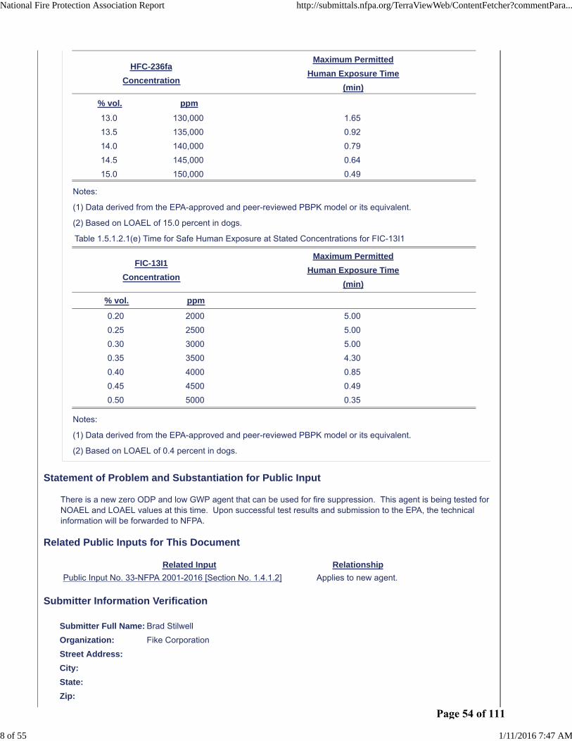
There is a new zero ODP and low GWP agent that can be used for fire suppression. This agent is being tested for NOAEL and LOAEL values at this time. Upon successful test results and submission to the EPA, the technical information will be forwarded to NFPA.
Related Public Inputs for This Document
Related Input Relationship
Public Input No. 34-NFPA 2001-2016 [Section No. 1.5.1.2.1]
Public Input No. 35-NFPA 2001-2016 [Section No. 4.2.1.1.1]
Public Input No. 36-NFPA 2001-2016 [Section No. A.1.4.1]
Public Input No. 37-NFPA 2001-2016 [Section No. A.1.5.1.2]
Public Input No. 38-NFPA 2001-2016 [Section No. A.1.6]
Public Input No. 39-NFPA 2001-2016 [Section No. A.4.1.4.1]
Public Input No. 40-NFPA 2001-2016 [Section No. A.5.4.2]
Public Input No. 41-NFPA 2001-2016 [Section No. A.5.4.2.2]
Public Input No. 42-NFPA 2001-2016 [Section No. A.5.5.1]
Public Input No. 43-NFPA 2001-2016 [Section No. C.2.7.1.3]
Submitter Information Verification
Submitter Full Name: Brad Stilwell
Organization: Fike Corporation
Street Address:
City:
State:
Zip:
Submittal Date: Tue Jan 05 12:26:54 EST 2016
National Fire Protection Association Report http://submittals.nfpa.org/TerraViewWeb/ContentFetcher?commentPara...
2 of 55 1/11/2016 7:47 AM
Page 48 of 111

Public Input No. 52-NFPA 2001-2016 [ Section No. 1.4.2.2 ]
1.4.2.2 *
Clean agents shall not be used on fires involving the following materials unless the agents have beentested to the satisfaction of the authority having jurisdiction:
(1) Certain chemicals or mixtures of chemicals, such as cellulose nitrate and gunpowder, which arecapable of rapid oxidation in the absence of air
(2) Reactive metals such as lithium, sodium, potassium, magnesium, titanium, zirconium, uranium, andplutonium
(3) Metal hydrides
(4) Chemicals capable of undergoing autothermal decomposition, such as certain organic peroxides, pyrophoric materials and hydrazine
Statement of Problem and Substantiation for Public Input
Pyrophoric chemicals are liquids and solids that have the potential to spontaneously ignite in air at temperatures of 130o F (54o C) or below. They often also have corrosive, water reactive, and peroxide forming properties.* Examples of pyrophoric materials include organometallic reagents such as alkyllithiums, alkylzincs, alkylmagnesiums (Grignards) and some finely divided metal powders. Specific examples include diborane (B2H6), diethylzinc (Zn(CH2CH3)2), tert-butyllithium (LiC(CH3)3) and diphosphine (P2H4). Use of clean extinguishing agents to extinguish fires involving such materials must be considered in the same as other special fire hazards included in this paragraph.* http://www.dehs.umn.edu/PDFs/Pyrophoric_Chemicals_Guide.pdf http://www.ilpi.com/msds/ref/pyrophoric.html
Submitter Information Verification
Submitter Full Name: Paul Rivers
Organization: 3M Company
Street Address:
City:
State:
Zip:
Submittal Date: Thu Jan 07 17:43:25 EST 2016
National Fire Protection Association Report http://submittals.nfpa.org/TerraViewWeb/ContentFetcher?commentPara...
3 of 55 1/11/2016 7:47 AM
Page 49 of 111

Public Input No. 34-NFPA 2001-2016 [ Section No. 1.5.1.2.1 ]
National Fire Protection Association Report http://submittals.nfpa.org/TerraViewWeb/ContentFetcher?commentPara...
4 of 55 1/11/2016 7:47 AM
Page 50 of 111

1.5.1.2.1*
National Fire Protection Association Report http://submittals.nfpa.org/TerraViewWeb/ContentFetcher?commentPara...
5 of 55 1/11/2016 7:47 AM
Page 51 of 111

Unnecessary exposure to halocarbon clean agents — including exposure at and below the no observableadverse effects level (NOAEL) — and halocarbon decomposition products shall be avoided. Means shall beprovided to limit exposure to no longer than 5 minutes. Unprotected personnel shall not enter a protectedspace during or after agent discharge. The following additional provisions shall apply:
(1) Halocarbon systems for spaces that are normally occupied and designed to concentrations up to theNOAEL [see Table 1.5.1.2.1(a)] shall be permitted. The maximum exposure in any case shall notexceed 5 minutes.
(2) Halocarbon systems for spaces that are normally occupied and designed to concentrations above theNOAEL [see Table 1.5.1.2.1(a)] shall be permitted if means are provided to limit exposure to thedesign concentrations shown in Table 1.5.1.2.1(b) through Table 1.5.1.2.1(e) that correspond to anallowable human exposure time of 5 minutes. Higher design concentrations associated with humanexposure times less than 5 minutes as shown in Table 1.5.1.2.1(b) through Table 1.5.1.2.1(e)shall notbe permitted in normally occupied spaces. An exposure and egress analysis shall be performed andapproved.
(3) In spaces that are not normally occupied and protected by a halocarbon system designed toconcentrations above the lowest observable adverse effects level (LOAEL) [see Table 1.5.1.2.1(a) ]and where personnel could possibly be exposed, means shall be provided to limit exposure timesusing Table 1.5.1.2.1(b) through Table 1.5.1.2.1(e).
(4) In spaces that are not normally occupied and in the absence of the information needed to fulfill theconditions listed in 1.5.1.2.1(3), the following provisions shall apply:
(5) Where egress takes longer than 30 seconds but less than 1 minute, the halocarbon agent shallnot be used in a concentration exceeding its LOAEL.
(6) Concentrations exceeding the LOAEL shall be permitted provided that any personnel in thearea can escape within 30 seconds.
(7) A pre-discharge alarm and time delay shall be provided in accordance with the provisions of4.3.5.6 of this standard.
Table 1.5.1.2.1(a) Information for Halocarbon Clean Agents
AgentNOAEL
(% vol.)
LOAEL
(% vol.)
FK-5-1-12 10.0 >10.0
HCFC Blend A 10.0 >10.0
HCFC-124 1.0 2.5
HFC-125 7.5 10.0
HFC-227ea 9.0 10.5
HFC-23 30 >30
HFC-236fa 10 15
HFC Blend B* 5.0* 7.5*
New Agent TBA TBA
*These values are for the largest component of the blend (HFC 134A).
Table 1.5.1.2.1(b) Time for Safe Human Exposure at Stated Concentrations for HFC-125
HFC-125
Concentration
Maximum Permitted
Human Exposure Time
(min)
% vol. ppm
7.5 75,000 5.00
8.0 80,000 5.00
8.5 85,000 5.00
National Fire Protection Association Report http://submittals.nfpa.org/TerraViewWeb/ContentFetcher?commentPara...
6 of 55 1/11/2016 7:47 AM
Page 52 of 111

HFC-125
Concentration
Maximum Permitted
Human Exposure Time
(min)
% vol. ppm
9.0 90,000 5.00
9.5 95,000 5.00
10.0 100,000 5.00
10.5 105,000 5.00
11.0 110,000 5.00
11.5 115,000 5.00
12.0 120,000 1.67
12.5 125,000 0.59
13.0 130,000 0.54
13.5 135,000 0.49
Notes:
(1) Data derived from the EPA-approved and peer-reviewed physiologically based pharmacokinetic (PBPK)model or its equivalent.
(2) Based on LOAEL of 10.0 percent in dogs.
Table 1.5.1.2.1(c) Time for Safe Human Exposure at Stated Concentrations for HFC-227ea
HFC-227ea
Concentration
Maximum Permitted
Human Exposure Time
(min)
% vol. ppm
9.0 90,000 5.00
9.5 95,000 5.00
10.0 100,000 5.00
10.5 105,000 5.00
11.0 110,000 1.13
11.5 115,000 0.60
12.0 120,000 0.49
Notes:
(1) Data derived from the EPA-approved and peer-reviewed PBPK model or its equivalent.
(2) Based on LOAEL of 10.5 percent in dogs.
Table 1.5.1.2.1(d) Time for Safe Human Exposure at Stated Concentrations for HFC-236fa
HFC-236fa
Concentration
Maximum Permitted
Human Exposure Time
(min)
% vol. ppm
10.0 100,000 5.00
10.5 105,000 5.00
11.0 110,000 5.00
11.5 115,000 5.00
12.0 120,000 5.00
12.5 125,000 5.00
National Fire Protection Association Report http://submittals.nfpa.org/TerraViewWeb/ContentFetcher?commentPara...
7 of 55 1/11/2016 7:47 AM
Page 53 of 111
HFC-236fa
Concentration
Maximum Permitted
Human Exposure Time
(min)
% vol. ppm
13.0 130,000 1.65
13.5 135,000 0.92
14.0 140,000 0.79
14.5 145,000 0.64
15.0 150,000 0.49
Notes:
(1) Data derived from the EPA-approved and peer-reviewed PBPK model or its equivalent.
(2) Based on LOAEL of 15.0 percent in dogs.
Table 1.5.1.2.1(e) Time for Safe Human Exposure at Stated Concentrations for FIC-13I1
FIC-13I1
Concentration
Maximum Permitted
Human Exposure Time
(min)
% vol. ppm
0.20 2000 5.00
0.25 2500 5.00
0.30 3000 5.00
0.35 3500 4.30
0.40 4000 0.85
0.45 4500 0.49
0.50 5000 0.35
Notes:
(1) Data derived from the EPA-approved and peer-reviewed PBPK model or its equivalent.
(2) Based on LOAEL of 0.4 percent in dogs.
Statement of Problem and Substantiation for Public Input
There is a new zero ODP and low GWP agent that can be used for fire suppression. This agent is being tested for NOAEL and LOAEL values at this time. Upon successful test results and submission to the EPA, the technical information will be forwarded to NFPA.
Related Public Inputs for This Document
Related Input Relationship
Public Input No. 33-NFPA 2001-2016 [Section No. 1.4.1.2] Applies to new agent.
Submitter Information Verification
Submitter Full Name: Brad Stilwell
Organization: Fike Corporation
Street Address:
City:
State:
Zip:
National Fire Protection Association Report http://submittals.nfpa.org/TerraViewWeb/ContentFetcher?commentPara...
8 of 55 1/11/2016 7:47 AM
Page 54 of 111

Submittal Date: Tue Jan 05 12:28:45 EST 2016
National Fire Protection Association Report http://submittals.nfpa.org/TerraViewWeb/ContentFetcher?commentPara...
9 of 55 1/11/2016 7:47 AM
Page 55 of 111

Public Input No. 7-NFPA 2001-2015 [ Chapter 2 ]
National Fire Protection Association Report http://submittals.nfpa.org/TerraViewWeb/ContentFetcher?commentPara...
10 of 55 1/11/2016 7:47 AM
Page 56 of 111

Chapter 2 Referenced Publications
2.1 General.
The documents or portions thereof listed in this chapter are referenced within this standard and shall beconsidered part of the requirements of this document.
2.2 NFPA Publications.
National Fire Protection Association, 1 Batterymarch Park, Quincy, MA 02169-7471.
NFPA 70 ® , National Electrical Code ® , 2014 edition.
NFPA 72 ® , National Fire Alarm and Signaling Code, 2013 edition.
2.3 Other Publications.
2.3.1 ANSI Publications.
American National Standards Institute, Inc., 25 West 43rd Street, 4th Floor, New York, NY 10036.
ANSI
B1
Z535 .
20.1
4 , Standard for
Pipe Threads, General Purpose, 1983 (R2006).
ANSI C2, National Electrical Safety Code , 2012.
ANSI Z535, Standard for
Environmental and Facility Safety Signs , 2011.
2.3.2 ASME Publications.
American Society of Mechanical Engineers
ASME International , Two Park Avenue, New York, NY 10016-5990.
Boiler and Pressure Vessel Code , 2015 .
ASME B1.20.1, Standard for Pipe Threads, General Purpose, 2013.
ASME B31.1, Power Piping ,
2012
2014 .
2.3.3 ASTM Publications.
ASTM International, 100 Barr Harbor Drive, P.O. Box C700, West Conshohocken, PA 19428-2959.
ASTM A53/A53M, Standard Specification for Pipe, Steel, Black and Hot-Dipped, Zinc-Coated,Welded and Seamless, 2012. (Superesedes ASTM A120 )
ASTM A120 , Specification for Seamless Carbon Steel Pipe for High Temperature Service, 1988.
ASTM SI10, American National Standard for Metric Practice , 2010.
2.3.4 CGA Publications.
Compressed Gas Association, 14501 George Carter Way, Suite 103, Chantilly, VA 20151-2923.
CGA C-6, Standard for Visual Inspection of Steel Compressed Gas Cylinders ,
2007CAN/CSA-
2013 .
2.3.5 CSA Publications.
Canadian Standards Association, 5060 Spectrum Way, Suite 100, Mississauga, ON L4W 5N6, Canada.
National Fire Protection Association Report http://submittals.nfpa.org/TerraViewWeb/ContentFetcher?commentPara...
11 of 55 1/11/2016 7:47 AM
Page 57 of 111

CSA Group, 178 Rexdale Blvd., Toronto ON, Canada, M9W 1R3 .
CSA Z234.1, Canadian Metric Practice Guide , 2000 (R2011). Withdrawn.
2.3.6 IEEE Publications.
IEEE, 445 and 501 Hoes Lane, Piscataway, NJ 08854-4141.
IEEE C2, National Electrical Safety Code (NESC), 2012.
2.3.7 IMO Publications.
International Maritime Organization, 4 Albert Embankment, London, England, SE1 7SR United Kingdom.
Fire Safety Systems (FSS) Code, 2007. (Includes below referenced circular)
IMO MSC/Circular 848, Revised Guidelines for the Approval of Equivalent Fixed Gas Fire-ExtinguishingSystems as Referred to in SOLAS 74, for Machinery Spaces and Cargo Pump-Rooms , 1998.
2.3.
7
8 ISO Publications.
International Organization for Standardization,
1 ch. de la Voie-Creuse, Case postale 56, CH-1211 Geneve 20,
ISO Central Secretariat, BIBC II, 8, Chemin de Blandonnet, CP 401, 1214 Vernier, Geneva,Switzerland .
ISO 7-1 , Pipe Threads Where Pressure-Tight Joints Are Made on the Threads — Part 1: Dimensions,Tolerances and Designation ,
1994
2007 .
2.3.
8
9 TC Publications.
Transport Canada, Tower C, Place de Ville, 330 Sparks Street, Ottawa, Ontario, K1A 0N5, Canada.
TP 127 E, Ship Safety Electrical Standards , 2008.
2.3.
9
10 UL Publications.
Underwriters Laboratories Inc., 333 Pfingsten Road, Northbrook, IL 60062-2096.
ANSI/
UL 2127, Standard for Inert Gas Clean Agent Extinguishing System Units ,
2012
2015 .
ANSI/
UL 2166, Standard for Halocarbon Clean Agent Extinguishing System Units ,
2012
2015 .
2.3.
10
11 ULC Publications.
Underwriters Laboratories of Canada, 7 Underwriters Road, Toronto, ON M1R 3B4, Canada.
ULC CAN
National Fire Protection Association Report http://submittals.nfpa.org/TerraViewWeb/ContentFetcher?commentPara...
12 of 55 1/11/2016 7:47 AM
Page 58 of 111

/ULC S524-06
S524 , Standard for the Installation of Fire Alarm Systems ,
2011
2014 .
CAN/
ULC S529
-09
, Smoke Detectors for Fire Alarm Systems , 2009.
2.3.
11
12 U.S. Government Publications.
U.S.
Government Printing
Government Publishing Office, 732 North Capitol Street, NW, Washington DC ,
DC 20402
20401-0001 .
OSHA, Title 29, Code of Federal Regulations, Part 1910, Subpart S.
USCG Title 46, Code of Federal Regulations, Part 72.
USCG Title 46, Code of Federal Regulations, Subchapter J, “Electrical Engineering.”
DOT Title 49, Code of Federal Regulations, Parts 170–190, “Transportation.”
2.3.
12
13 Other Publications.
Merriam-Webster’s Collegiate Dictionary , 11th edition, Merriam-Webster, Inc., Springfield, MA, 2003.
2.4 References for Extracts in Mandatory Sections.
NFPA 12, Standard on Carbon Dioxide Extinguishing Systems, 2015 edition.
Statement of Problem and Substantiation for Public Input
Referenced current SDO names, addresses, standard names, numbers and editions.
Related Public Inputs for This Document
Related Input Relationship
Public Input No. 8-NFPA 2001-2015 [Chapter E]
Submitter Information Verification
Submitter Full Name: Aaron Adamczyk
Organization: [ Not Specified ]
Street Address:
City:
State:
Zip:
Submittal Date: Sun Jul 19 00:47:03 EDT 2015
National Fire Protection Association Report http://submittals.nfpa.org/TerraViewWeb/ContentFetcher?commentPara...
13 of 55 1/11/2016 7:47 AM
Page 59 of 111

Public Input No. 47-NFPA 2001-2016 [ Section No. 2.2 ]
2.2 NFPA Publications.
National Fire Protection Association, 1 Batterymarch Park, Quincy, MA 02169-7471.
NFPA 4, Standard for Integrated Fire Protection and Life Safety System Testing, 2015 edition.
NFPA 70® , National Electrical Code®, 2014 edition.
NFPA 72® , National Fire Alarm and Signaling Code, 2013 edition.
Statement of Problem and Substantiation for Public Input
Adding with acceptance of Public Input 44.
Submitter Information Verification
Submitter Full Name: Kimberly Gruner
Organization: Fike Corporation
Street Address:
City:
State:
Zip:
Submittal Date: Wed Jan 06 14:36:15 EST 2016
National Fire Protection Association Report http://submittals.nfpa.org/TerraViewWeb/ContentFetcher?commentPara...
14 of 55 1/11/2016 7:47 AM
Page 60 of 111

Public Input No. 29-NFPA 2001-2016 [ Section No. 2.3.9 ]
2.3.9 UL Publications.
Underwriters Laboratories Inc., 333 Pfingsten Road, Northbrook, IL 60062-2096.
ANSI/UL 2127, Standard for Inert Gas Clean Agent Extinguishing System Units, 2012, Revised 2015 .
ANSI/UL 2166, Standard for Halocarbon Clean Agent Extinguishing System Units, 2012, Revised 2015 .
Statement of Problem and Substantiation for Public Input
UL Referenced Standards have been updated/revised to a newer edition.
Submitter Information Verification
Submitter Full Name: Ronald Farr
Organization: Ul Llc
Street Address:
City:
State:
Zip:
Submittal Date: Tue Jan 05 11:14:59 EST 2016
National Fire Protection Association Report http://submittals.nfpa.org/TerraViewWeb/ContentFetcher?commentPara...
15 of 55 1/11/2016 7:47 AM
Page 61 of 111

Public Input No. 48-NFPA 2001-2016 [ Section No. 2.3.10 ]
2.3.10 ULC Publications.
Underwriters Laboratories of Canada, 7 Underwriters Road, Toronto, ON M1R 3B4, Canada.
CAN/ULC S524-06 14 , Standard for the Installation of Fire Alarm Systems, 2011 2014 .
CAN/ULC S529-09, Smoke Detectors for Fire Alarm Systems, 2009.
Statement of Problem and Substantiation for Public Input
ULC referenced standard has been revised/updated to a newer edition.
Submitter Information Verification
Submitter Full Name: Ronald Farr
Organization: Ul Llc
Street Address:
City:
State:
Zip:
Submittal Date: Thu Jan 07 09:16:20 EST 2016
National Fire Protection Association Report http://submittals.nfpa.org/TerraViewWeb/ContentFetcher?commentPara...
16 of 55 1/11/2016 7:47 AM
Page 62 of 111

Public Input No. 55-NFPA 2001-2016 [ Section No. 4.1.4.4 ]
4.1.4.4
A means shall be provided to determine and monitor the pressure in containers of inert gas agents,superpressurized liquid agents, and superpressurized liquefied compressed gas agents and to providenotification of a low pressure condition . Visual and audible signals in the protected area and a troublesignal to a constantly attended remote or central station alarm service shall be provided to indicate alow-pressure condition.
Statement of Problem and Substantiation for Public Input
There currently is no specific requirement to monitor and alert responsible persons for a low-pressure condition in land-based clean extinguishing agent systems. Currently, if there is a low pressure condition, such a condition can exist without responsible persons knowing of the condition. Providing this requirement alleviates that condition and is consistent with similar requirements in paragraph 8.6.5.
Submitter Information Verification
Submitter Full Name: Paul Rivers
Organization: 3M Company
Street Address:
City:
State:
Zip:
Submittal Date: Thu Jan 07 17:54:34 EST 2016
National Fire Protection Association Report http://submittals.nfpa.org/TerraViewWeb/ContentFetcher?commentPara...
17 of 55 1/11/2016 7:47 AM
Page 63 of 111

Public Input No. 28-NFPA 2001-2016 [ Section No. 4.2.1.1.1 ]
National Fire Protection Association Report http://submittals.nfpa.org/TerraViewWeb/ContentFetcher?commentPara...
18 of 55 1/11/2016 7:47 AM
Page 64 of 111

4.2.1.1.1
National Fire Protection Association Report http://submittals.nfpa.org/TerraViewWeb/ContentFetcher?commentPara...
19 of 55 1/11/2016 7:47 AM
Page 65 of 111

In no case shall the value used for the minimum pipe design pressure be less than that specified in Table4.2.1.1.1(a) and Table 4.2.1.1.1(b) for the conditions shown. For inert gas clean agents that employ theuse of a pressure-reducing device, Table 4.2.1.1.1(a) shall be used for piping upstream of the pressurereducer, and 4.2.1.1.2 shall be used to determine minimum pipe design pressure for piping downstream ofthe pressure reducer. The pressure-reducing device shall be readily identifiable. For halocarbon cleanagents, Table 4.2.1.1.1(b) shall be used. If different fill densities, pressurization levels, or higher storagetemperatures from those shown in Table 4.2.1.1.1(a) or Table 4.2.1.1.1(b) are approved for a givensystem, the minimum design pressure for the piping shall be adjusted to the maximum pressure in theagent container at maximum temperature, using the basic design criteria specified in 4.2.1.1(1) and4.2.1.1(2) .
Table 4.2.1.1.1(a) Minimum Design Working Pressure for Inert Gas Clean Agent System Piping
Agent Container GaugePressure at 70°F
(21°C)
Agent Container GaugePressure at 130°F (55°C)
Minimum Design Pressure ofPiping Upstream of Pressure
Reducer
Agent psi kPa psi kPa psi kPa
IG-01 2370 16,341 2650 18,271 2370 16,341
2964 20,436 3304 22,781 2964 20,436
4510 31,097 5402 37,244 4510 31,097
IG-541 2175 14,997 2575 17,755 2175 14,997
2900 19,996 3433 23,671 2900 19,996
4503 31,050 5359 36,950 4503 31,050
IG-55 2175 15,000 2541 17,600 2175 15,000
2900 20,000 3434 23,700 2900 20,000
4350 30,000 5222 36,100 4350 30,000
IG-100 2404 16,575 2799 19,299 2404 16,575
3236 22,312 3773 26,015 3236 22,312
4061 28,000 4754 32,778 4061 28,000
Table 4.2.1.1.1(b) Minimum Design Working Pressure for Halocarbon Clean Agent System Piping
Agent ContainerMaximum Fill Density
Agent ContainerCharging Pressure
at 70°F (21°C)
AgentContainerPressure
at 130°F (55°C)
Minimum PipingDesign Pressure
Agent lb/ft3 kg/m3 psi bar psi bar psi bar
HFC-227ea 79 1265 44* 3 135 9 416 29
75 1201 150 10 249 17 200 14
72 1153 360 25 520 36 416 29
72 1153 600 41 1025 71 820 57
HCFC BlendA
56.2 900 600 41 850 59 680 47
56.2 900 360 25 540 37 432 30
HFC 23 54 865 608.9† 42 2182 150 1746 120
48 769 608.9† 42 1713 118 1371 95
45 721 608.9† 42 1560 108 1248 86
40 641 608.9† 42 1382 95 1106 76
35 561 608.9† 42 1258 87 1007 69
30 481 608.9† 42 1158 80 927 64
HCFC-124 74 1185 240 17 354 24 283 20
National Fire Protection Association Report http://submittals.nfpa.org/TerraViewWeb/ContentFetcher?commentPara...
20 of 55 1/11/2016 7:47 AM
Page 66 of 111

Agent ContainerMaximum Fill Density
Agent ContainerCharging Pressure
at 70°F (21°C)
AgentContainerPressure
at 130°F (55°C)
Minimum PipingDesign Pressure
Agent lb/ft3 kg/m3 psi bar psi bar psi bar
HCFC-124 74 1185 360 25 580 40 464 32
HFC-125 54 865 360 25 615 42 492 34
HFC 125 56 897 600 41 1045 72 836 58
HFC-236fa 74 1185 240 17 360 25 280 19
HFC-236fa 75 1201 360 25 600 41 480 33
HFC-236fa 74 1185 600 41 1100 76 880 61
HFC BlendB
58 929 360 25 586 40 469 32
58 929 600 41 888 61 710 50
FK-5-1-12 90 1442 150 10 175 12 150 10
90 1442 195 13 225 16 195 13
90 1442 360 25 413 28 360 25
75 1201 500 34 575 40 500 34
90 1442 610 42 700 48 610 42
*Nitrogen delivered to agent cylinder through a flow restrictor upon system actuation. Nitrogen supplycylinder pressure is 1800 psi (124 bar) at 70°F (21°C).
†Not superpressurized with nitrogen.
Additional Proposed Changes
File Name Description Approved
Table_Addition_4.2.1.1.1_a_.xlsx Add Information to existing table
Statement of Problem and Substantiation for Public Input
300 bar IG-541 added to existing table to cover existing systems.
Submitter Information Verification
Submitter Full Name: Katherine Adrian
Organization: Tyco Fire Protection Products
Street Address:
City:
State:
Zip:
Submittal Date: Mon Jan 04 13:25:57 EST 2016
National Fire Protection Association Report http://submittals.nfpa.org/TerraViewWeb/ContentFetcher?commentPara...
21 of 55 1/11/2016 7:47 AM
Page 67 of 111

Addition to Table 4.2.1.1.1(a) Minimum Design Working Pressure for Inert Gas Clean Agent System Pipi
Agent psi kPa psi kPa psi kPa
IG‐541 4352 30,006 4998 34460 4352 30,006
Minimum Design
Pressure of Piping
Upstream of Pressure
Reducer
Agent Container Gauge
Pressure at 70°F(21°C)
Agent Container GaugePressure at 130°F (55°C)
Page 68 of 111

ing
Page 69 of 111

Public Input No. 35-NFPA 2001-2016 [ Section No. 4.2.1.1.1 ]
National Fire Protection Association Report http://submittals.nfpa.org/TerraViewWeb/ContentFetcher?commentPara...
22 of 55 1/11/2016 7:47 AM
Page 70 of 111

4.2.1.1.1
National Fire Protection Association Report http://submittals.nfpa.org/TerraViewWeb/ContentFetcher?commentPara...
23 of 55 1/11/2016 7:47 AM
Page 71 of 111

In no case shall the value used for the minimum pipe design pressure be less than that specified in Table4.2.1.1.1(a) and Table 4.2.1.1.1(b) for the conditions shown. For inert gas clean agents that employ the useof a pressure-reducing device, Table 4.2.1.1.1(a) shall be used for piping upstream of the pressure reducer,and 4.2.1.1.2 shall be used to determine minimum pipe design pressure for piping downstream of thepressure reducer. The pressure-reducing device shall be readily identifiable. For halocarbon clean agents,Table 4.2.1.1.1(b) shall be used. If different fill densities, pressurization levels, or higher storagetemperatures from those shown in Table 4.2.1.1.1(a) or Table 4.2.1.1.1(b) are approved for a givensystem, the minimum design pressure for the piping shall be adjusted to the maximum pressure in theagent container at maximum temperature, using the basic design criteria specified in 4.2.1.1(1) and4.2.1.1(2).
Table 4.2.1.1.1(a) Minimum Design Working Pressure for Inert Gas Clean Agent System Piping
Agent Container GaugePressure at 70°F
(21°C)
Agent Container GaugePressure at 130°F (55°C)
Minimum Design Pressure ofPiping Upstream of Pressure
Reducer
Agent psi kPa psi kPa psi kPa
IG-01 2370 16,341 2650 18,271 2370 16,341
2964 20,436 3304 22,781 2964 20,436
4510 31,097 5402 37,244 4510 31,097
IG-541 2175 14,997 2575 17,755 2175 14,997
2900 19,996 3433 23,671 2900 19,996
4503 31,050 5359 36,950 4503 31,050
IG-55 2175 15,000 2541 17,600 2175 15,000
2900 20,000 3434 23,700 2900 20,000
4350 30,000 5222 36,100 4350 30,000
IG-100 2404 16,575 2799 19,299 2404 16,575
3236 22,312 3773 26,015 3236 22,312
4061 28,000 4754 32,778 4061 28,000
Table 4.2.1.1.1(b) Minimum Design Working Pressure for Halocarbon Clean Agent System Piping
Agent ContainerMaximum Fill Density
Agent ContainerCharging Pressure
at 70°F (21°C)
AgentContainerPressure
at 130°F (55°C)
Minimum PipingDesign Pressure
Agent lb/ft3 kg/m3 psi bar psi bar psi bar
HFC-227ea 79 1265 44* 3 135 9 416 29
75 1201 150 10 249 17 200 14
72 1153 360 25 520 36 416 29
72 1153 600 41 1025 71 820 57
HCFC BlendA
56.2 900 600 41 850 59 680 47
56.2 900 360 25 540 37 432 30
HFC 23 54 865 608.9† 42 2182 150 1746 120
48 769 608.9† 42 1713 118 1371 95
45 721 608.9† 42 1560 108 1248 86
40 641 608.9† 42 1382 95 1106 76
35 561 608.9† 42 1258 87 1007 69
30 481 608.9† 42 1158 80 927 64
HCFC-124 74 1185 240 17 354 24 283 20
National Fire Protection Association Report http://submittals.nfpa.org/TerraViewWeb/ContentFetcher?commentPara...
24 of 55 1/11/2016 7:47 AM
Page 72 of 111

Agent ContainerMaximum Fill Density
Agent ContainerCharging Pressure
at 70°F (21°C)
AgentContainerPressure
at 130°F (55°C)
Minimum PipingDesign Pressure
Agent lb/ft3 kg/m3 psi bar psi bar psi bar
HCFC-124 74 1185 360 25 580 40 464 32
HFC-125 54 865 360 25 615 42 492 34
HFC 125 56 897 600 41 1045 72 836 58
HFC-236fa 74 1185 240 17 360 25 280 19
HFC-236fa 75 1201 360 25 600 41 480 33
HFC-236fa 74 1185 600 41 1100 76 880 61
HFC BlendB
58 929 360 25 586 40 469 32
58 929 600 41 888 61 710 50
FK-5-1-12 90 1442 150 10 175 12 150 10
90 1442 195 13 225 16 195 13
90 1442 360 25 413 28 360 25
75 1201 500 34 575 40 500 34
90 1442 610 42 700 48 610 42
New Agent TBA TBA 360 25 TBA TBA TBA TBA
*Nitrogen delivered to agent cylinder through a flow restrictor upon system actuation. Nitrogen supplycylinder pressure is 1800 psi (124 bar) at 70°F (21°C).
†Not superpressurized with nitrogen.
Statement of Problem and Substantiation for Public Input
There is a new zero ODP and low GWP agent that can be used for fire suppression. This agent is being tested for NOAEL and LOAEL values at this time. Upon successful test results and submission to the EPA, the technical information will be forwarded to NFPA.
Related Public Inputs for This Document
Related Input Relationship
Public Input No. 33-NFPA 2001-2016 [Section No. 1.4.1.2] New agent requirement.
Submitter Information Verification
Submitter Full Name: Brad Stilwell
Organization: Fike Corporation
Street Address:
City:
State:
Zip:
Submittal Date: Tue Jan 05 12:31:46 EST 2016
National Fire Protection Association Report http://submittals.nfpa.org/TerraViewWeb/ContentFetcher?commentPara...
25 of 55 1/11/2016 7:47 AM
Page 73 of 111

Public Input No. 25-NFPA 2001-2015 [ New Section after 4.2.1.5 ]
Dirt trap.
A dirt trap consisting of a tee with a capped nipple, at least 50 mm (2 inches) long , shall be installed atthe end of each pipe run.
Statement of Problem and Substantiation for Public Input
1. Regardless of initial pipe cleanliness, rust and scale can form in pipes over time.2. Loosened pipe scale will be discharged into the protected space, thereby contaminating that space and negating the principle of "clean" that is a basis of "clean agent" systems..3. Dirt traps are required by ISO 14520, 6.3.1.2, which demonstrates that the international community for fixed-gas fire extinguishing systems recognizes risk related to pipe scale.
Submitter Information Verification
Submitter Full Name: Joseph Senecal
Organization: Kidde-Fenwal, Inc.
Street Address:
City:
State:
Zip:
Submittal Date: Wed Dec 16 14:55:35 EST 2015
National Fire Protection Association Report http://submittals.nfpa.org/TerraViewWeb/ContentFetcher?commentPara...
26 of 55 1/11/2016 7:47 AM
Page 74 of 111

Public Input No. 45-NFPA 2001-2016 [ New Section after 4.2.3.7 ]
TITLE OF NEW CONTENT
Type your content here ...
4.2.3.8 Where grooved fittings are used to join pipe, the manufacturer's pressure and temperature ratings ofthe fitting shall not be exceeded.
Statement of Problem and Substantiation for Public Input
Table A.4.2.3.1(a) includes grooved couplings as acceptable fittings for clean agent systems. Note "b" in the Table states: "Check with grooved fitting manufacturers for pressure ratings." The proposed 4.2.3.8 would make it mandatory to follow the manufacturer's pressure and temperature ratings for grooved fittings.
The addition parallels 4.2.3.7 which addresses compression type fittings and is in keeping with the NFPA manual of style.
Submitter Information Verification
Submitter Full Name: John Spalding
Organization: Healey Fire Protection, Inc.
Affilliation: Fire Suppression Systems Association
Street Address:
City:
State:
Zip:
Submittal Date: Wed Jan 06 14:12:26 EST 2016
National Fire Protection Association Report http://submittals.nfpa.org/TerraViewWeb/ContentFetcher?commentPara...
27 of 55 1/11/2016 7:47 AM
Page 75 of 111

Public Input No. 1-NFPA 2001-2015 [ Section No. 4.3.1.2 [Excluding any Sub-Sections] ]
Automatic detection and automatic actuation shall be used. The use of a dry contact closure from anotherfire alarm control unit providing the detection shall not be permitted.Detection devices within the protecteddspace shall be connected to the fire alarm control unit listed for releasing the suppression agent.
Statement of Problem and Substantiation for Public Input
Many systems are being installed with a building fire alarm system being used for activation of a fire alarm control unit listed for releasing through a dry contact interface. The fire alarm control unit responsible for releasing is required to be a standalone unit monitored by the building fire alarm system unless the building fire alarm system is providing both the detection and the release of the suppression agent. This revision will correct and clarify the requirements for automatic detection and functionality of the fire alarm control unit responsible for release of the suppression agent. This dry contact interface used is an unsupervised connection and is often not installed within 3' of the control unit used for releasing the suppression agent. Additionally a relay is not considered a detection device even though it may be activated by another fire alarm control unit with automatic detection devices.
Submitter Information Verification
Submitter Full Name: JON KAPIS
Organization: SABAH INTERNATIONAL
Affilliation: None
Street Address:
City:
State:
Zip:
Submittal Date: Wed Jul 08 16:10:50 EDT 2015
National Fire Protection Association Report http://submittals.nfpa.org/TerraViewWeb/ContentFetcher?commentPara...
28 of 55 1/11/2016 7:47 AM
Page 76 of 111

Public Input No. 19-NFPA 2001-2015 [ Section No. 4.3.1.3 ]
4.3.1.3 *
Initiating and releasing circuits shall be installed in raceways.
4.3.1.3.1 Other than as permitted in 4.3.1.3.1 2 , alternating current (ac) and direct current (dc) wiring shallnot be combined in a common conduit or raceway.
4.3.1.3.1 2
It shall be permitted to combine ac and dc wiring in a common conduit or raceway where shielded andgrounded.
4.3.1.3.2.3
The requirements of 4.3.1.3 for initiating circuits shall not apply to the wireless pathways of low-power radiosystems.
A.4.3.1.3
The use of raceways is intended to protect against physical damage to conductors and cabling.
Statement of Problem and Substantiation for Public Input
The two (2) requirements of 4.3.1.3 were separated in accordance with the Manual of Style.The proposed change recognizes the advancement in technology for the use of wireless detection systems.The Annex material addresses the reason for initiating and releasing circuits to be in raceways.
Submitter Information Verification
Submitter Full Name: John Spalding
Organization: Healey Fire Protection Inc
Affilliation: Fire Suppression Systems Association
Street Address:
City:
State:
Zip:
Submittal Date: Wed Nov 25 15:01:26 EST 2015
National Fire Protection Association Report http://submittals.nfpa.org/TerraViewWeb/ContentFetcher?commentPara...
29 of 55 1/11/2016 7:47 AM
Page 77 of 111

Public Input No. 49-NFPA 2001-2016 [ Section No. 4.3.1.3 ]
4.3.1.3 *
Initiating and releasing circuits shall be installed in raceways.
4.3.1.3.1
Other than as permitted in 4.3.1.3.
1
2 , alternating current (ac) and direct current (dc) wiring shall not be combined in a common conduit orraceway.
4.3.1.3.
1
2 It shall be permitted to combine ac and dc wiring in a common conduit or raceway where shielded andgrounded.
4.3.1.3.3 The requirements of 4.3.1.3 shall not apply to the wireless pathways of low-power radio systems.
A.4.3.1.3 The use of raceways is intended to protect against physical damage to conductors and cabling.
Statement of Problem and Substantiation for Public Input
To clarify that this requirement is intended to guard against physical damage to conductors and cabling. The two requirements of 4.3.1.3 were separated in accordance with the Manual of Style. Also 4.3.1.3 implies that wireless technology is not permitted. This will clarify that the above section refers to both wired and wireless as permitted by NFPA 72.
Submitter Information Verification
Submitter Full Name: Vince Baclawski
Organization: Nema
Street Address:
City:
State:
Zip:
Submittal Date: Thu Jan 07 09:32:15 EST 2016
National Fire Protection Association Report http://submittals.nfpa.org/TerraViewWeb/ContentFetcher?commentPara...
30 of 55 1/11/2016 7:47 AM
Page 78 of 111

Public Input No. 3-NFPA 2001-2015 [ New Section after 4.3.5.2 ]
TITLE OF NEW CONTENT
Type your content here ...4.3.5.2.1 Audible and visisble alarms for pending discharge or continued operationafter discharge shall not function during a building fire alarm event, unless casued by the event within theprotected area.
Statement of Problem and Substantiation for Public Input
This language will ensure that the building notification appliances are not activated within the protected area when the notification appliances used to signal pre-discharge and continuing discharge of the suppression agent, thus eliminating conflicting and completing signals. This would require that building alarm notification appliances are seperately zoned for the protected area and capable of being controlled to eliminate conflicting and competing signals.
Submitter Information Verification
Submitter Full Name: JON KAPIS
Organization: SABAH INTERNATIONAL
Street Address:
City:
State:
Zip:
Submittal Date: Wed Jul 08 16:19:51 EDT 2015
National Fire Protection Association Report http://submittals.nfpa.org/TerraViewWeb/ContentFetcher?commentPara...
31 of 55 1/11/2016 7:47 AM
Page 79 of 111

Public Input No. 54-NFPA 2001-2016 [ New Section after 6.3 ]
6.3.1
The design quantity to ensure complete extinguishment shall be confirmed by test.
Statement of Problem and Substantiation for Public Input
No performance based requirement exists to verify that the quantity used is indeed sufficient to extinguish the fire. Requiring a test to determine that extinguishment provides a mechanism to validate the suppression solution is effective. It also aligns with the requirements included in paragraph 5.4.2.
Related Public Inputs for This Document
Related Input Relationship
Public Input No. 53-NFPA 2001-2016 [Section No. 6.3] 6.3.1 is subparagraph to 6.3.
Submitter Information Verification
Submitter Full Name: Paul Rivers
Organization: 3M Company
Street Address:
City:
State:
Zip:
Submittal Date: Thu Jan 07 17:50:30 EST 2016
National Fire Protection Association Report http://submittals.nfpa.org/TerraViewWeb/ContentFetcher?commentPara...
32 of 55 1/11/2016 7:47 AM
Page 80 of 111

Public Input No. 53-NFPA 2001-2016 [ Section No. 6.3 ]
6.3 Clean Agent Requirements.
The design quantity of clean agent required for local application systems shall be based on the rate ofdischarge and the time that the discharge must be maintained to ensure complete extinguishment. Theminimum design quantity shall be no less than 1.5 times the minimum quantity required for extinguishmentat any selected system discharge rate.
Statement of Problem and Substantiation for Public Input
The quantity of agent needs to be defined as that designed. That design quantity should be determined by test.
Related Public Inputs for This Document
Related Input Relationship
Public Input No. 54-NFPA 2001-2016 [New Section after 6.3]
Submitter Information Verification
Submitter Full Name: Paul Rivers
Organization: 3M Company
Street Address:
City:
State:
Zip:
Submittal Date: Thu Jan 07 17:46:14 EST 2016
National Fire Protection Association Report http://submittals.nfpa.org/TerraViewWeb/ContentFetcher?commentPara...
33 of 55 1/11/2016 7:47 AM
Page 81 of 111

Public Input No. 24-NFPA 2001-2015 [ New Section after 7.1.3.3 ]
Owners Inspection.
On a monthly basis, inspection shall be conducted in accordance with the manufacturer’s listed installationand maintenance manual orowner’s manual.
As a minimum, this “quick check” or inspection shall include verification of the following:
(1)Release panel is in service.
(2)Manual actuators are unobstructed.
(3)Maintenance Tag is in place.
(4)System shows no physical damage or condition that might prevent operation.
(5)Pressure gauges if provided are in required operational range.
(6)Protected equipment and or hazard has not been changed and or modified.
(7)Noted deficiencies have been corrected.
If any deficiencies are found, appropriate corrective action shall be taken immediately.
Where the corrective action involves maintenance, it shall be conducted by a service technician.
Personnel making inspections shall keep records for those extinguishing systems that were found torequire corrective actions.
At least monthly, the date the inspection is performed and the initials of the person performing theinspection shall be recorded. The recordsshall be retained until the next semiannual maintenance.
A service technician who performs maintenance on an extinguishing system shall be trained and shall havepassed a written or online test that is acceptable to the authority having jurisdiction.
Additional Proposed Changes
File Name Description Approved
2001_PC_3_-_Held.pdf PC 3 held
Statement of Problem and Substantiation for Public Input
Note: This Public Input originated as Public Comment No. 18 and was reported at as "Reject but Hold" in the F2014 Second Draft Report for NFPA 79, per the Regs at 4.4.8.3.1.Submitter's Substantiation: Provide documentation by owner's representative that due diligence is being performed checking that systems are being maintained in service.
Submitter Information Verification
Submitter Full Name: TC GFE-AAA
Organization: NFPA
Street Address:
City:
State:
Zip:
Submittal Date: Tue Dec 15 10:31:57 EST 2015
National Fire Protection Association Report http://submittals.nfpa.org/TerraViewWeb/ContentFetcher?commentPara...
34 of 55 1/11/2016 7:47 AM
Page 82 of 111

Public Comment No. 3-NFPA 2001-2013 [ New Section after 7.1.3.3 ]
TITLE OF NEW CONTENT
Owners Inspection.
On a monthly basis, inspection shall be conducted in accordance with the manufacturer’s listed installation and maintenance manual orowner’s manual.
As a minimum, this “quick check” or inspection shall include verification of the following:
(1) Release panel is in service.
(2) Manual actuators are unobstructed
(3) Maintenance Tag is in place.
(4) System shows no physical damage or condition that might prevent operation.
(5) Pressure gauges if provided are in required operational range.
(6) Protected equipment and or hazard has not been changed and or modified.
(7) Noted deficiencies have been corrected.
If any deficiencies are found, appropriate corrective action shall be taken immediately.
Where the corrective action involves maintenance, it shall be conducted by a service technician
Personnel making inspections shall keep records for those extinguishing systems that were found to require corrective actions.
At least monthly, the date the inspection is performed and the initials of the person performing the inspection shall be recorded. The recordsshall be retained until the next semiannual maintenance.
A service technician who performs maintenance on an extinguishing system shall be trained and shall have passed a written or online testthat is acceptable to the authority having jurisdiction.
Statement of Problem and Substantiation for Public Comment
Provide documentation by owners representative that due dilligence is being performed checking that systems are being maintained in service.
Submitter Information Verification
Submitter Full Name: BEN SMITH
Organization: GLOBAL RISK CONSULTANTS
Affilliation: Member
Street Address:
City:
State:
Zip:
Submittal Date: Tue Nov 05 13:28:45 EST 2013
Committee Statement
CommitteeAction:
Rejected but held
Resolution: The committee agrees that this concept should be included in the standard. However, it constitutes new material at this time and isbeing held for further consideration at the next revision cycle.
National Fire Protection Association Report http://submittals.nfpa.org/TerraViewWeb/ContentFetcher?commentPara...
13 of 32 6/13/2014 2:37 PM
Page 83 of 111

Public Input No. 44-NFPA 2001-2016 [ New Section after 7.7.1 ]
7.7.1.2
Systems integrated with the Clean Agent Fire Extinguishing System shall be planned, tested, documented,and maintained in accordance with NFPA 4 Standard for Integrated Fire Protection and Life SafetySystem Testing.
Statement of Problem and Substantiation for Public Input
Many installations utilize various individual systems (Fire Suppression, Fire Alarm or signaling system, emergency communication system, fire doors, dampers, elevators, smoke control, HVAC, supervising station, etc.) for fire protection and life safety where each may utilize their own code, standard, or acceptance criteria. NFPA 4 is a new standard that provides requirements for testing integrated systems together so that the entire fire protection and life safety system objective is accomplished.
Submitter Information Verification
Submitter Full Name: Kimberly Gruner
Organization: Fike Corporation
Street Address:
City:
State:
Zip:
Submittal Date: Wed Jan 06 14:10:45 EST 2016
National Fire Protection Association Report http://submittals.nfpa.org/TerraViewWeb/ContentFetcher?commentPara...
35 of 55 1/11/2016 7:47 AM
Page 84 of 111

Public Input No. 46-NFPA 2001-2016 [ Section No. 7.7.1 ]
7.7.1 General.
7.7.1.1 The completed system shall be reviewed and tested by qualified personnel to meet the approval ofthe authority having jurisdiction. Only listed equipment and devices shall be used in the systems. Todetermine that the system has been properly installed and will function as specified, the following tests shallbe performed.
Statement of Problem and Substantiation for Public Input
Adding a section number to conform with manual of style upon acceptance of Public Input 44.
Submitter Information Verification
Submitter Full Name: Kimberly Gruner
Organization: Fike Corporation
Street Address:
City:
State:
Zip:
Submittal Date: Wed Jan 06 14:31:51 EST 2016
National Fire Protection Association Report http://submittals.nfpa.org/TerraViewWeb/ContentFetcher?commentPara...
36 of 55 1/11/2016 7:47 AM
Page 85 of 111

Public Input No. 36-NFPA 2001-2016 [ Section No. A.1.4.1 ]
National Fire Protection Association Report http://submittals.nfpa.org/TerraViewWeb/ContentFetcher?commentPara...
37 of 55 1/11/2016 7:47 AM
Page 86 of 111

A.1.4.1
National Fire Protection Association Report http://submittals.nfpa.org/TerraViewWeb/ContentFetcher?commentPara...
38 of 55 1/11/2016 7:47 AM
Page 87 of 111

The agents currently listed possess the physical properties as detailed in Table A.1.4.1(a) through TableA.1.4.1(d). These data will be revised from time to time as new information becomes available. Additionalbackground information and data on these agents can be found in several references: Fernandez (1991),Hanauska (1991), Robin (1991), and Sheinson (1991).
Table A.1.4.1(a) Physical Properties of Clean Halocarbon Agents (U.S. Units)
PhysicalProperty
Units FIC-13I1 FK-5-1-12HCFCBlend
A
HFCBlend
BHCFC-124 HFC-125 HFC-227ea HFC-23 HFC
Molecularweight
N/A 195.9 316.04 92.9 99.4 136.5 120.0 170 70.01 1
Boilingpoint at760 mm Hg
°F -8.5 120.2 -37 -14.9 10.5 -54 2.4 -115.6 29
Freezingpoint
°F -166 -162.4 161 -153.9 -326 -153 -204 -247.4 -15
Criticaltemperature
°F 252 335.6 256 219.9 252.5 150.8 214 79.1 25
Criticalpressure
psi 586 270.44 964 588.9 527 525 424 700 46
Criticalvolume ft3/lbm 0.0184 0.0251 0.028 0.031 0.0286 0.0279 0.0280 0.0304 0.02
Criticaldensity lbm/ft3 54.38 39.91 36 32.17 34.96 35.81 35.77 32.87 34
Specificheat, liquidat 77°F
Btu/lb-°F 0.141 0.2634 0.3 0.339 0.271 0.354 0.2810.987 at
68°F0.3
Specificheat, vaporat constantpressure
(1 atm)
and 77°F
Btu/lb-°F 0.86 0.2127 0.16 0.203 0.18 0.19 0.1930.175 at
68°F0.2
Heat ofvaporizationat boilingpoint
Btu/lb 48.1 37.8 97 93.4 71.3 70.5 56.6 103 68
Thermalconductivityof liquid at77°F
Btu/hr-ft-°F 0.04 0.034 0.052 0.0478 0.0395 0.0343 0.034 0.0305 0.0
Viscosity,liquid at77°F
lb/ft-hr 0.473 1.27 0.508 0.485 0.622 0.338 0.579 0.107 0.6
Relativedielectricstrength at
1 atm at734 mmHg, (N2 =
1)
N/A1.41 at77°F
2.3 at
77°F
1.32 at77°F
1.014at
77°F
1.55 at77°F
0.955 at70°F
2 at
77°F
1.04 at77°F
1.0177
Solubility ofwater inagent
wt%0.01 at70°F
<0.001 at70°F
0.12 at70°F
0.11 at70°F
770 at
77°F
770 at
77°F0.06 at 70°F
500 at
50°F
74
68
Table A.1.4.1(b) Physical Properties of Inert Gas Agents (U.S. Units)
National Fire Protection Association Report http://submittals.nfpa.org/TerraViewWeb/ContentFetcher?commentPara...
39 of 55 1/11/2016 7:47 AM
Page 88 of 111

Physical Property Units IG-01 IG-100 IG-541 IG-55
Molecular weight N/A 39.9 28.0 34.0 33.95
Boiling point at 760 mm Hg °F -302.6 -320.4 -320 -310.2
Freezing point °F -308.9 -346.0 -109 -327.5
Critical temperature °F -188.1 -232.4 N/A -210.5
Critical pressure psia 711 492.9 N/A 602
Specific heat, vapor at constant pressure (1 atm) and 77°F Btu/lb °F 0.125 0.445 0.195 0.187
Heat of vaporization at boiling point Btu/lb 70.1 85.6 94.7 77.8
Relative dielectric strength at
1 atm at 734 mm Hg, 77°F
(N2 = 1.0)
N/A 1.01 1.0 1.03 1.01
Solubility of water in agent at 77°F N/A 0.006% 0.0013% 0.015% 0.006%
Table A.1.4.1(c) Physical Properties of Clean Halocarbon Agents (SI Units)
PhysicalProperty
Units FIC-13I1 FK-5-1-12
HCFC
BlendA
HFC
BlendB
HCFC-124 HFC-125 HFC-227ea HFC-23 HFC-
Molecularweight
N/A 195.91 316.04 92.90 99.4 136.5 120 170 70.01 15
Boilingpoint at760 mm Hg
°C -22.5 49 -38.3 -26.1 -12.0 -48.1 -16.4 -82.1 -1
Freezingpoint
°C -110 -108 <107.2 -103 -198.9 -102.8 -131 -155.2 -10
Criticaltemperature
°C 122 168.66 124.4 101.1 122.6 66 101.7 26.1 124
Criticalpressure
kPa 4041 1865 6647 4060 3620 3618 2912 4828 32
Criticalvolume
cc/mole 225 494.5 162 198 243 210 274 133 27
Criticaldensity kg/m3 871 639.1 577 515.3 560 574 621 527 551
Specificheat,
liquid at25°C
kJ/kg - °C0.592 at
25°C1.103 at
25°C
1.256at
25°C
1.44 at25°C
1.153 at25°C
1.407 at25°C
1.184 at25°C
4.130 at
20°C
1.2625
Specificheat, vaporat constantpressure (1atm) and25°C
kJ/kg - °C0.3618 at
25°C0.891 at
25°C0.67 at25°C
0.848at
25°C
0.742 at25°C
0.797 at25°C
0.808 at25°C
0.731 at
20°C
0.8425
Heat ofvaporizationat boilingpoint
kJ/kg 112.4 88 225.6 217.2 165.9 164.1 132.6 239.3 160
Thermalconductivityof liquid at25°C
W/m - °C 0.07 0.059 0.09 0.082 0.0684 0.0592 0.069 0.0534 0.07
National Fire Protection Association Report http://submittals.nfpa.org/TerraViewWeb/ContentFetcher?commentPara...
40 of 55 1/11/2016 7:47 AM
Page 89 of 111

PhysicalProperty
Units FIC-13I1 FK-5-1-12
HCFC
BlendA
HFC
BlendB
HCFC-124 HFC-125 HFC-227ea HFC-23 HFC-
Viscosity,liquid at25°C
centipoise 0.196 0.524 0.21 0.202 0.257 0.14 0.184 0.044 0.2
Relativedielectricstrength at
1 atm at734
mm Hg
(N2 = 1.0)
N/A1.41 at25°C
2.3 at25°C
1.32 at25°C
1.014at
25°C
1.55 at25°C
0.955 at21°C
2 at 25°C1.04 at25°C
1.01625
Solubility ofwater inagent
ppm1.0062%by weight
<0.0010.12%
byweight
0.11%by
weight
700 at25°C
700 at25°C
0.06% byweight
500 at10°C
740
20
Table A.1.4.1(d) Physical Properties of Inert Gas Agents (SI Units)
Physical Property Units IG-01 IG-100 IG-541 IG-55
Molecular weight N/A 39.9 28.0 34.0 33.95
Boiling point at 760 mm Hg °C -189.85 -195.8 -196 -190.1
Freezing point °C -189.35 -210.0 -78.5 -199.7
Critical temperature °C -122.3 -146.9 N/A -134.7
Critical pressure kPa 4,903 3,399 N/A 4,150
Specific heat, vapor at constant pressure (1 atm) and 25°C kJ/kg °C 0.519 1.04 0.574 0.782
Heat of vaporization at boiling point kJ/kg 163 199 220 181
Relative dielectric strength at
1 atm at 734 mm Hg, 25°C
(N2 = 1.0)
N/A 1.01 1.0 1.03 1.01
Solubility of water in agent at 25°C N/A 0.006% 0.0013% 0.015% 0.006%
Statement of Problem and Substantiation for Public Input
There is a new zero ODP and low GWP agent that can be used for fire suppression. This agent is being tested for NOAEL and LOAEL values at this time. Upon successful test results and submission to the EPA, the technical information will be forwarded to NFPA.
Related Public Inputs for This Document
Related Input Relationship
Public Input No. 33-NFPA 2001-2016 [Section No. 1.4.1.2] Required for new agent
Submitter Information Verification
Submitter Full Name: Brad Stilwell
Organization: Fike Corporation
Street Address:
City:
State:
Zip:
National Fire Protection Association Report http://submittals.nfpa.org/TerraViewWeb/ContentFetcher?commentPara...
41 of 55 1/11/2016 7:47 AM
Page 90 of 111

Submittal Date: Tue Jan 05 12:37:27 EST 2016
National Fire Protection Association Report http://submittals.nfpa.org/TerraViewWeb/ContentFetcher?commentPara...
42 of 55 1/11/2016 7:47 AM
Page 91 of 111

Public Input No. 37-NFPA 2001-2016 [ Section No. A.1.5.1.2 ]
National Fire Protection Association Report http://submittals.nfpa.org/TerraViewWeb/ContentFetcher?commentPara...
43 of 55 1/11/2016 7:47 AM
Page 92 of 111

A.1.5.1.2
National Fire Protection Association Report http://submittals.nfpa.org/TerraViewWeb/ContentFetcher?commentPara...
44 of 55 1/11/2016 7:47 AM
Page 93 of 111

Table A.1.5.1.2(a) provides information on the toxicological effects of halocarbon agents covered by thisstandard. The no observable adverse effect level (NOAEL) is the highest concentration at which no adversephysiological or toxicological effect has been observed. The lowest observable adverse effect level(LOAEL) is the lowest concentration at which an adverse physiological or toxicological effect has beenobserved.
An appropriate protocol measures the effect in a stepwise manner such that the interval between theLOAEL and NOAEL is sufficiently small to be acceptable to the competent regulatory authority. The EPAincludes in its SNAP evaluation this aspect (of the rigor) of the test protocol.
Table A.1.5.1.2(a) Toxicity Information for Halocarbon Clean Agents
Agent
LC50 or ALC
(%)
NOAEL
(%)
LOAEL
(%)
FIC-13I1 >12.8 0.2 0.4
FK-5-1-12 >10.0 10 >10.0
HCFC Blend A 64 10 >10.0
HCFC-124 23–29 1 2.5
HFC-125 >70 7.5 10
HFC-227ea >80 9 10.5
HFC-23 >65 30 >30
HFC-236fa >45.7 10 15
HFC Blend B 56.7* 5.0* 7.5*
New Agent TBA TBA TBA
Notes:
(1) LC50 is the concentration lethal to 50 percent of a rat population during a 4 hour exposure. The ALC is
the approximate lethal concentration.
(2) The cardiac sensitization levels are based on the observance or nonobservance of serious heartarrhythmias in a dog. The usual protocol is a 5 minute exposure followed by a challenge with epinephrine.
(3) High concentration values are determined with the addition of oxygen to prevent asphyxiation.
*These values are for the largest component of the blend (HFCB 134A).
For halocarbons covered in this standard, the NOAEL and LOAEL are based on the toxicological effectknown as cardiac sensitization. Cardiac sensitization occurs when a chemical causes an increasedsensitivity of the heart to adrenaline, a naturally occurring substance produced by the body during times ofstress, leading to the sudden onset of irregular heart beats and possibly heart attack. Cardiac sensitizationis measured in dogs after they have been exposed to a halocarbon agent for 5 minutes. At the 5 minutetime period, an external dose of adrenaline (epinephrine) is administered and an effect is recorded if thedog experiences cardiac sensitization. The cardiac sensitization potential as measured in dogs is a highlyconservative indicator of the potential in humans. The conservative nature of the cardiac sensitization teststems from several factors; the two most pertinent are as follows:
(1) Very high doses of adrenaline are given to the dogs during the testing procedure (doses are morethan 10 times higher than the highest levels secreted by humans under maximum stress).
(2) Four to ten times more halocarbon is required to cause cardiac sensitization in the absence ofexternally administered adrenaline, even in artificially created situations of stress or fright in the dogtest.
Because the cardiac sensitization potential is measured in dogs, a means of providing human relevance tothe concentration at which this cardiac sensitization occurs (LOAEL) has been established through the useof physiologically based pharmacokinetic (PBPK) modeling.
A PBPK model is a computerized tool that describes time-related aspects of a chemical’s distribution in abiological system. The PBPK model mathematically describes the uptake of the halocarbon into the bodyand the subsequent distribution of the halocarbon to the areas of the body where adverse effects can occur.For example, the model describes the breathing rate and uptake of the halocarbon from the exposureatmosphere into the lungs. From there, the model uses the blood flow bathing the lungs to describe the
National Fire Protection Association Report http://submittals.nfpa.org/TerraViewWeb/ContentFetcher?commentPara...
45 of 55 1/11/2016 7:47 AM
Page 94 of 111

movement of the halocarbon from the lung space into the arterial blood that directly feeds the heart andvital organs of the body.
It is the ability of the model to describe the halocarbon concentration in human arterial blood that providesits primary utility in relating the dog cardiac sensitization test results to a human who is unintentionallyexposed to the halocarbon. The concentration of halocarbon in the dog arterial blood at the time the cardiacsensitization event occurs (5 minute exposure) is the critical arterial blood concentration, and this bloodparameter is the link to the human system. Once this critical arterial blood concentration has beenmeasured in dogs, the EPA-approved PBPK model simulates how long it will take the human arterial bloodconcentration to reach the critical arterial blood concentration (as determined in the dog test) during humaninhalation of any particular concentration of the halocarbon agent. As long as the simulated human arterialconcentration remains below the critical arterial blood concentration, the exposure is considered safe.Inhaled halocarbon concentrations that produce human arterial blood concentrations equal to or greaterthan the critical arterial blood concentration are considered unsafe because they represent inhaledconcentrations that potentially yield arterial blood concentrations where cardiac sensitization events occurin the dog test. Using these critical arterial blood concentrations of halocarbons as the ceiling for allowablehuman arterial concentrations, any number of halocarbon exposure scenarios can be evaluated using thismodeling approach.
For example, in the dog cardiac sensitization test on Halon 1301, a measured dog arterial bloodconcentration of 25.7 mg/L is measured at the effect concentration (LOAEL) of 7.5 percent after a 5 minuteexposure to Halon 1301 and an external intravenous adrenaline injection. The PBPK model predicts thetime at which the human arterial blood concentration reaches 25.7 mg/L for given inhaled Halon 1301concentrations. Using this approach, the model also predicts that at some inhaled halocarbonconcentrations, the critical arterial blood concentration is never reached; thus, cardiac sensitization will notoccur. Accordingly, in the tables in 1.5.1.2.1, the time is arbitrarily truncated at 5 minutes, because the dogswere exposed for 5 minutes in the original cardiac sensitization testing protocols.
The time value, estimated by the EPA-approved and peer-reviewed PBPK model or its equivalent, is thatrequired for the human arterial blood level for a given halocarbon to equal the arterial blood level of a dogexposed to the LOAEL for 5 minutes.
For example, if a system is designed to achieve a maximum concentration of 12.0 percent HFC-125,means should be provided such that personnel are exposed for no longer than 1.67 minutes. Examples ofsuitable exposure-limiting mechanisms include self-contained breathing apparatuses and planned andrehearsed evacuation routes.
The requirement for pre-discharge alarms and time delays is intended to prevent human exposure toagents during fire fighting. However, in the unlikely circumstance that an accidental discharge occurs,restrictions on the use of certain halocarbon agents covered in this standard are based on the availability ofPBPK modeling information. For those halocarbon agents in which modeling information is available,means should be provided to limit the exposure to those concentrations and times specified in the tables in1.5.1.2.1. The concentrations and times given in the tables are those that have been predicted to limit thehuman arterial blood concentration to below the critical arterial blood concentration associated with cardiacsensitization. For halocarbon agents where the needed data are unavailable, the agents are restrictedbased on whether the protected space is normally occupied or unoccupied and how quickly egress from thearea can be effected. Normally occupied areas are those intended for human occupancy. Normallyunoccupied areas are those in which personnel can be present from time to time. Therefore, a comparisonof the cardiac sensitization values to the intended design concentration would determine the suitability of ahalocarbon for use in normally occupied or unoccupied areas.
Clearly, longer exposure of the agent to high temperatures would produce greater concentrations of thesegases. The type and sensitivity of detection, coupled with the rate of discharge, should be selected tominimize the exposure time of the agent to the elevated temperature if the concentration of the breakdownproducts must be minimized. In most cases the area would be untenable for human occupancy due to theheat and breakdown products of the fire itself.
These decomposition products have a sharp, acrid odor, even in minute concentrations of only a few partsper million. This characteristic provides a built-in warning system for the agent but at the same time createsa noxious, irritating atmosphere for those who must enter the hazard following a fire.
Background and toxicology of hydrogen fluoride. Hydrogen fluoride (HF) vapor can be produced in fires asa breakdown product of fluorocarbon fire extinguishing agents and in the combustion of fluoropolymers.
The significant toxicological effects of HF exposure occur at the site of contact. By the inhalation route,significant deposition is predicted to occur in the most anterior (front part) region of the nose and extending
National Fire Protection Association Report http://submittals.nfpa.org/TerraViewWeb/ContentFetcher?commentPara...
46 of 55 1/11/2016 7:47 AM
Page 95 of 111

back to the lower respiratory tract (airways and lungs) if sufficient exposure concentrations are achieved.The damage induced at the site of contact with HF is characterized by extensive tissue damage and celldeath (necrosis) with inflammation. One day after a single, 1 hour exposure of rats to HF concentrations of950 ppm to 2600 ppm, tissue injury was limited exclusively to the anterior section of the nose (DuPont,1990). No effects were seen in the trachea or lungs.
At high concentrations of HF (about 200 ppm), human breathing patterns would be expected to changeprimarily from nose breathing to primarily mouth breathing. This change in breathing pattern determines thedeposition pattern of HF into the respiratory tract, either upper respiratory tract (nose breathing) or lowerrespiratory tract (mouth breathing). In studies conducted by Dalby (1996), rats were exposed by nose-onlyor mouth-only breathing. In the mouth-only breathing model, rats were exposed to various concentrations ofHF through a tube placed in the trachea, thereby bypassing the upper respiratory tract. This exposuremethod is considered to be a conservative approach for estimating a “worst case” exposure in which aperson would not breathe through the nose but inhale through the mouth, thereby maximizing thedeposition of HF into the lower respiratory tract.
In the nose-only breathing model, 2 minute or 10 minute exposures of rats to about 6400 or 1700 ppm,respectively, produced similar effects; that is, no mortality resulted but significant cell damage in the nosewas observed. In contrast, marked differences in toxicity were evident in the mouth-only breathing model.Indeed, mortality was evident following a 10 minute exposure to a concentration of about 1800 ppm and a2 minute exposure to about 8600 ppm. Significant inflammation of the lower respiratory tract was alsoevident. Similarly, a 2 minute exposure to about 4900 ppm produced mortality and significant nasaldamage. However, at lower concentrations (950 ppm) following a 10 minute exposure or 1600 ppmfollowing a 2 minute exposure, no mortality and only minimal irritation were observed.
Numerous other toxicology studies have been conducted in experimental animals for longer durations, suchas 15, 30, or 60 minutes. In nearly all of these studies, the effects of HF were generally similar across allspecies; that is, severe irritation of the respiratory tract was observed as the concentration of HF wasincreased.
In humans, an irritation threshold appears to be at about 3 ppm, where irritation of the upper airways andeyes occurs. In prolonged exposure at about 5 ppm, redness of the skin has also resulted. In controlledhuman exposure studies, humans are reported to have tolerated mild nasal irritation (subjective response)at 32 ppm for several minutes (Machle et al., 1934). Exposure of humans to about 3 ppm for an hourproduced slight eye and upper respiratory tract irritation. Even with an increase in exposure concentration(up to 122 ppm) and a decrease in exposure duration to about 1 minute, skin, eye, and respiratory tractirritation occurs (Machle and Kitzmiller, 1935).
Meldrum (1993) proposed the concept of the dangerous toxic load (DTL) as a means of predicting theeffects of, for example, HF in humans. Meldrum developed the argument that the toxic effects of certainchemicals tend to follow Haber’s law:
[A.1.5.1.2]
where:
C = concentration
t = time
k = constant
The available data on the human response to inhalation of HF were considered insufficient to provide abasis for establishing a DTL. Therefore, it was necessary to use the available animal lethality data toestablish a model for the response in humans. The DTL is based on an estimate of 1 percent lethality in anexposed population of animals. Based on the analysis of animal lethality data, the author determined thatthe DL for HF is 12,000 ppm/min. Although this approach appears reasonable and consistent with mortalitydata in experimental animals, the predictive nature of this relationship for nonlethal effects in humans hasnot been demonstrated.
Potential human health effects and risk analysis in fire scenarios. It is important for a risk analysis todistinguish between normally healthy individuals, such as fire fighters, and those with compromised health.Exposure to higher concentrations of HF would be expected to be tolerated more in healthy individuals,whereas equal concentrations can have escape-impairing effects in those with compromised health. Thefollowing discussion assumes that the effects described at the various concentrations and durations are forthe healthy individual.
Inflammation (irritation) of tissues represents a continuum from “no irritation” to “severe, deep penetrating”
National Fire Protection Association Report http://submittals.nfpa.org/TerraViewWeb/ContentFetcher?commentPara...
47 of 55 1/11/2016 7:47 AM
Page 96 of 111

irritation. Use of the terms slight, mild, moderate, and severe in conjunction with irritation represents anattempt to quantify this effect. However, given the large variability and sensitivity of the human population,differences in the degree of irritation from exposure to HF are expected to occur. For example, someindividuals can experience mild irritation to a concentration that results in moderate irritation in anotherindividual.
At concentrations of <50 ppm for up to 10 minutes, irritation of upper respiratory tract and the eyes wouldbe expected to occur. At these low concentrations, escape-impairing effects would not be expected in thehealthy individual. As HF concentrations increase to 50 ppm to 100 ppm, an increase in irritation isexpected. For short duration (10 to 30 minutes), irritation of the skin, eyes, and respiratory tract wouldoccur. At 100 ppm for 30 to 60 minutes, escape-impairing effects would begin to occur, and continuedexposure at 200 ppm and greater for an hour could be lethal in the absence of medical intervention. As theconcentration of HF increases, the severity of irritation increases, and the potential for delayed systemiceffects also increases. At about 100 to 200 ppm of HF, humans would also be expected to shift theirbreathing pattern to mouth breathing. Therefore, deeper lung irritation is expected. At greaterconcentrations (>200 ppm), respiratory discomfort, pulmonary (deep lung) irritation, and systemic effectsare possible. Continued exposure at these higher concentrations can be lethal in the absence of medicaltreatment.
Generation of HF from fluorocarbon fire extinguishing agents represents a potential hazard. In the foregoingdiscussion, the duration of exposure was indicated for 10 to 60 minutes. In fire conditions in which HFwould be generated, the actual exposure duration would be expected to be less than 10 minutes and inmost cases less than 5 minutes. As Dalby (1996) showed, exposing mouth-breathing rats to HFconcentrations of about 600 ppm for 2 minutes was without effect. Similarly, exposing mouth-breathing ratsto a HF concentration of about 300 ppm for 10 minutes did not result in any mortality or respiratory effects.Therefore, one could surmise that humans exposed to similar concentrations for less than 10 minuteswould be able to survive such concentrations. However, caution needs to be employed in interpreting thesedata. Although the toxicity data would suggest that humans could survive these large concentrations forless than 10 minutes, those individuals with compromised lung function or those with cardiopulmonarydisease can be more susceptible to the effects of HF. Furthermore, even in the healthy individual, irritationof the upper respiratory tract and eyes would be expected, and escape could be impaired.
Table A.1.5.1.2(b) provides potential human health effects of hydrogen fluoride in healthy individuals.
Occupational exposure limits have been established for HF. The limit set by the American Conference of
Governmental Industrial Hygienists (ACGIH), the Threshold Limit Value (TLV®), represents exposure ofnormally healthy workers for an 8 hour workday or a 40 hour workweek. For HF, the limit established is 3ppm, which represents a ceiling limit; that is, the airborne concentration that should not be exceeded at anytime during the workday. This limit is intended to prevent irritation and possible systemic effects withrepeated, long-term exposure. This and similar time-weighted average limits are not considered relevant forfire extinguishing use of fluorocarbons during emergency situations. However, these limits may need to beconsidered in clean-up procedures where high levels of HF were generated. (More information can beobtained from the American Conference of Governmental Industrial Hygienists, 1330 Kemper MeadowDrive, Cincinnati, OH 45240, 513-742-2020.)
Table A.1.5.1.2(b) Potential Human Health Effects of Hydrogen Fluoride in Healthy Individuals
Exposure
Time
Concentration of
HydrogenFluoride
(ppm)
Reaction
2 minutes <50 Slight eye and nasal irritation
50–100 Mild eye and upper respiratory tract irritation
100–200 Moderate eye and upper respiratory tract irritation; slight skin irritation
>200Moderate irritation of all body surfaces; increasing concentration may beescape impairing
5 minutes <50 Mild eye and nasal irritation
50–100 Increasing eye and nasal irritation; slight skin irritation
100–200 Moderate irritation of skin, eyes, and respiratory tract
National Fire Protection Association Report http://submittals.nfpa.org/TerraViewWeb/ContentFetcher?commentPara...
48 of 55 1/11/2016 7:47 AM
Page 97 of 111

Exposure
Time
Concentration of
HydrogenFluoride
(ppm)
Reaction
>200Definite irritation of tissue surfaces; will cause escape-impairing effects atincreasing concentrations
10 minutes <50 Definite eye, skin, and upper respiratory tract irritation
50–100 Moderate irritation of all body surfaces
100–200 Moderate irritation of all body surfaces; escape-impairing effects likely
>200Escape-impairing effects will occur; increasing concentrations can be lethalwithout medical intervention
In contrast to the ACGIH TLV, the American Industrial Hygiene Association (AIHA) Emergency ResponsePlanning Guideline (ERPG) represents limits established for emergency release of chemicals. These limitsare established to also account for sensitive populations, such as those with compromised health. TheERPG limits are designed to assist emergency response personnel in planning for catastrophic releases ofchemicals. These limits are not developed to be used as “safe” limits for routine operations. However, in thecase of fire extinguishing use and generation of HF, these limits are more relevant than time-weightedaverage limits such as the TLV. The ERPG limits consist of three levels for use in emergency planning andare typically 1 hour values; 10 minute values have also been established for HF. For the 1 hour limits, theERPG 1 (2 ppm) is based on odor perception and is below the concentration at which mild sensory irritationhas been reported (3 ppm). ERPG 2 (20 ppm) is the most important guideline value set and is theconcentration at which mitigating steps should be taken, such as evacuation, sheltering, and donningmasks. This level should not impede escape or cause irreversible health effects and is based mainly on thehuman irritation data obtained by Machle et al. (1934) and Largent (1960). ERPG 3 (50 ppm) is based onanimal data and is the maximum nonlethal level for nearly all individuals. This level could be lethal to somesusceptible people. The 10-minute values established for HF and used in emergency planning in fireswhere HF vapor is generated are ERPG 3 = 170 ppm, ERPG 2 = 50 ppm, and ERPG 1 = 2 ppm. (Moreinformation can be obtained from the American Industrial Hygiene Association, 2700 Prosperity Ave., Suite250, Fairfax, VA 22031, 703-849-8888, fax 703-207-3561.)
Statement of Problem and Substantiation for Public Input
There is a new zero ODP and low GWP agent that can be used for fire suppression. This agent is being tested for NOAEL and LOAEL values at this time. Upon successful test results and submission to the EPA, the technical information will be forwarded to NFPA.
Related Public Inputs for This Document
Related Input Relationship
Public Input No. 33-NFPA 2001-2016 [Section No. 1.4.1.2] Required for new agent
Submitter Information Verification
Submitter Full Name: Brad Stilwell
Organization: Fike Corporation
Street Address:
City:
State:
Zip:
Submittal Date: Tue Jan 05 12:41:50 EST 2016
National Fire Protection Association Report http://submittals.nfpa.org/TerraViewWeb/ContentFetcher?commentPara...
49 of 55 1/11/2016 7:47 AM
Page 98 of 111

Public Input No. 38-NFPA 2001-2016 [ Section No. A.1.6 ]
National Fire Protection Association Report http://submittals.nfpa.org/TerraViewWeb/ContentFetcher?commentPara...
50 of 55 1/11/2016 7:47 AM
Page 99 of 111

A.1.6
Many factors impact the environmental acceptability of a fire suppression agent. Uncontrolled fires posesignificant impact by themselves. All extinguishing agents should be used in ways that eliminate orminimize the potential environmental impact (see Table A.1.6). General guidelines to be followed tominimize this impact include the following:
(1) Not performing unnecessary discharge testing
(2) Considering the ozone depletion and global warming impact of the agent under consideration andweighing those impacts against the fire safety concerns
(3) Recycling all agents where possible
(4) Consulting the most recent environmental regulations on each agent
The unnecessary emission of clean extinguishing agents with non-zero ODP, non-zero GWP, or both shouldbe avoided. All phases of design, installation, testing, and maintenance of systems using these agentsshould be performed with the goal of no emission into the environment.
GWP is a measure of how much a given mass of greenhouse gas is estimated to contribute to globalwarming. It is a relative scale that compares the gas in question to the same mass of carbon dioxide whoseGWP is by convention equal to 1.
It is important to understand that the impact of a gas on climate change is a function of both the GWP of thegas and the amount of the gas emitted.
The ODP of an agent provides a relative comparison of the ability to react with ozone at altitudes within thestratosphere. ODP values are reported relative to the same mass CFC-11, which has an ODP equal to 1.When the environmental profile of a compound is considered, both the ODP and the GWP values should beconsidered to ensure that the agent selected complies with all local and regional regulations balanced withend user specifications. Good independent resources for environmental properties in terms of GWP andODP of clean agent alternatives are available from the Montreal Protocol and the Intergovernmental Panelon Climate Change (IPCC).
Table A.1.6 Potential Environmental Impacts
AgentGWP
(IPCC 2013)ODP
FIC-13I1 ≤1 0*
FK-5-1-12 ≤1 0
HCFC Blend A 1500 0.048
HFC Blend B 1400 0
HCFC-124 527 0.022
HFC-125 3170 0
HFC-227ea 3350 0
HFC-23 12,400 0
HFC-236fa 8060 0
IG-01 0 0
IG-100 0 0
IG-541 0 0
IG-55 0 0
New Agent TBA TBA
Note: GWP is reported over a 100-year integrated time horizon.
*Agent might have a nonzero ODP if released at altitudes high above ground level.
Statement of Problem and Substantiation for Public Input
There is a new zero ODP and low GWP agent that can be used for fire suppression. This agent is being tested for
National Fire Protection Association Report http://submittals.nfpa.org/TerraViewWeb/ContentFetcher?commentPara...
51 of 55 1/11/2016 7:47 AM
Page 100 of 111

NOAEL and LOAEL values at this time. Upon successful test results and submission to the EPA, the technical information will be forwarded to NFPA.
Related Public Inputs for This Document
Related Input Relationship
Public Input No. 33-NFPA 2001-2016 [Section No. 1.4.1.2] required for new agent
Submitter Information Verification
Submitter Full Name: Brad Stilwell
Organization: Fike Corporation
Street Address:
City:
State:
Zip:
Submittal Date: Tue Jan 05 12:50:59 EST 2016
National Fire Protection Association Report http://submittals.nfpa.org/TerraViewWeb/ContentFetcher?commentPara...
52 of 55 1/11/2016 7:47 AM
Page 101 of 111

Public Input No. 50-NFPA 2001-2016 [ Section No. A.1.6 ]
National Fire Protection Association Report http://submittals.nfpa.org/TerraViewWeb/ContentFetcher?commentPara...
53 of 55 1/11/2016 7:47 AM
Page 102 of 111

A.1.6
Many factors impact the environmental acceptability of a fire suppression agent. Uncontrolled fires posesignificant impact by themselves. All extinguishing agents should be used in ways that eliminate orminimize the potential environmental impact (see Table A.1.6). General guidelines to be followed tominimize this impact include the following:
(1) Not performing unnecessary discharge testing
(2) Considering the ozone depletion and global warming impact of the agent under consideration andweighing those impacts against the fire safety concerns
(3) Recycling all agents where possible
(4) Consulting the most recent environmental regulations on each agent
The unnecessary emission of clean extinguishing agents with non-zero ODP, non-zero GWP, or both shouldbe avoided. All phases of design, installation, testing, and maintenance of systems using these agentsshould be performed with the goal of no emission into the environment.
GWP is a measure of how much a given mass of greenhouse gas is estimated to contribute to globalwarming. It is a relative scale that compares the gas in question to the same mass of carbon dioxide whoseGWP is by convention equal to 1.
It is important to understand that the impact of a gas on climate change is a function of both the GWP of thegas and the amount of the gas emitted.
The ODP of an agent provides a relative comparison of the ability to react with ozone at altitudes within thestratosphere. ODP values are reported relative to the same mass CFC-11, which has an ODP equal to 1.When the environmental profile of a compound is considered, both the ODP and the GWP values should beconsidered to ensure that the agent selected complies with all local and regional regulations balanced withend user specifications. Good independent resources for environmental properties in terms of GWP andODP of clean agent alternatives are available from the Montreal Protocol and the Intergovernmental Panelon Climate Change (IPCC).
Table A.1.6 Potential Environmental Impacts
AgentGWP
(IPCC 2013)ODP
FIC-13I1 ≤1 0*
FK-5-1-12
≤1
<1 0
HCFC Blend A 1500 0.048
HFC Blend B 1400 0
HCFC-124 527 0.022
HFC-125 3170 0
HFC-227ea 3350 0
HFC-23 12,400 0
HFC-236fa 8060 0
IG-01 0 0
IG-100 0 0
IG-541 0 0
IG-55 0 0
Note: GWP is reported over a 100-year integrated time horizon.
*Agent might have a nonzero ODP if released at altitudes high above ground level.
Additional Proposed Changes
National Fire Protection Association Report http://submittals.nfpa.org/TerraViewWeb/ContentFetcher?commentPara...
54 of 55 1/11/2016 7:47 AM
Page 103 of 111

File Name Description Approved
14_feb_GWP_tables_from_WG1AR5_Chapter08.pdfTable 8.A.1 in the referenced IPCC AR 5 2013 report
Statement of Problem and Substantiation for Public Input
Corrected GWP data of <1 aligns with Table 8.A.1 in the referenced IPCC 2013 report. The chemical formula CF3CF2C(O)CF(CF3)2 in the report is the same as that associated with FK-5-1-12 in NFPA 2001, Table 1.4.1.2.
Submitter Information Verification
Submitter Full Name: Paul Rivers
Organization: 3M Company
Street Address:
City:
State:
Zip:
Submittal Date: Thu Jan 07 17:28:54 EST 2016
National Fire Protection Association Report http://submittals.nfpa.org/TerraViewWeb/ContentFetcher?commentPara...
55 of 55 1/11/2016 7:47 AM
Page 104 of 111

8
Anthropogenic and N
atural Radiative Forcing Chapter 8
731
Appendix 8.A: Lifetimes, Radiative Efficiencies and Metric Values
Table 8.A.1 | Radiative efficiencies (REs), lifetimes/adjustment times, AGWP and GWP values for 20 and 100 years, and AGTP and GTP values for 20, 50 and 100 years. Climate–carbon feedbacks are included for CO2 while no climate feedbacks are included for the other components (see discussion in Sections 8.7.1.4 and 8.7.2.1, Supplementary Material and notes below the table; Supplementary Material Table 8.SM.16 gives analogous values including climate–carbon feedbacks for non-CO2 emissions). For a complete list of chemical names and CAS numbers, and for accurate replications of metric values, see Supplementary Material Section 8.SM.13 and references therein.
Acronym, Common Name or Chemi-
cal Name
Chemical Formula
Lifetime(Years)
RadiativeEfficiency(W m–2
ppb–1)
AGWP20-year(W m–2
yr kg–1)
GWP20-year
AGWP100-year(W m–2
yr kg–1)
GWP100-year
AGTP20-year(K kg–1)
GTP20-year
AGTP50-year(K kg–1)
GTP50-year
AGTP100-year(K kg–1)
GTP100-year
Carbon dioxide CO2 see* 1.37e-5 2.49e-14 1 9.17e-14 1 6.84e-16 1 6.17e-16 1 5.47e-16 1
Methane CH4 12.4† 3.63e-4 2.09e-12 84 2.61e-12 28 4.62e-14 67 8.69e-15 14 2.34e-15 4
Fossil methane‡ CH4 12.4† 3.63e-4 2.11e-12 85 2.73e-12 30 4.68e-14 68 9.55e-15 15 3.11e-15 6
Nitrous Oxide N2O 121† 3.00e-3 6.58e-12 264 2.43e-11 265 1.89e-13 277 1.74e-13 282 1.28e-13 234
Chlorofluorocarbons
CFC-11 CCl3F 45.0 0.26 1.72e-10 6900 4.28e-10 4660 4.71e-12 6890 3.01e-12 4890 1.28e-12 2340
CFC-12 CCl2F2 100.0 0.32 2.69e-10 10,800 9.39e-10 10,200 7.71e-12 11,300 6.75e-12 11,000 4.62e-12 8450
CFC-13 CClF3 640.0 0.25 2.71e-10 10,900 1.27e-09 13,900 7.99e-12 11,700 8.77e-12 14,200 8.71e-12 15,900
CFC-113 CCl2FCClF2 85.0 0.30 1.62e-10 6490 5.34e-10 5820 4.60e-12 6730 3.85e-12 6250 2.45e-12 4470
CFC-114 CClF2CClF2 190.0 0.31 1.92e-10 7710 7.88e-10 8590 5.60e-12 8190 5.56e-12 9020 4.68e-12 8550
CFC-115 CClF2CF3 1,020.0 0.20 1.46e-10 5860 7.03e-10 7670 4.32e-12 6310 4.81e-12 7810 4.91e-12 8980
Hydrochlorofluorocarbons
HCFC-21 CHCl2F 1.7 0.15 1.35e-11 543 1.35e-11 148 1.31e-13 192 1.59e-14 26 1.12e-14 20
HCFC-22 CHClF2 11.9 0.21 1.32e-10 5280 1.62e-10 1760 2.87e-12 4200 5.13e-13 832 1.43e-13 262
HCFC-122 CHCl2CF2Cl 1.0 0.17 5.43e-12 218 5.43e-12 59 4.81e-14 70 6.25e-15 10 4.47e-15 8
HCFC-122a CHFClCFCl2 3.4 0.21 2.36e-11 945 2.37e-11 258 2.91e-13 426 2.99e-14 48 1.96e-14 36
HCFC-123 CHCl2CF3 1.3 0.15 7.28e-12 292 7.28e-12 79 6.71e-14 98 8.45e-15 14 6.00e-15 11
HCFC-123a CHClFCF2Cl 4.0 0.23 3.37e-11 1350 3.39e-11 370 4.51e-13 659 4.44e-14 72 2.81e-14 51
HCFC-124 CHClFCF3 5.9 0.20 4.67e-11 1870 4.83e-11 527 7.63e-13 1120 7.46e-14 121 4.03e-14 74
HCFC-132c CH2FCFCl2 4.3 0.17 3.07e-11 1230 3.10e-11 338 4.27e-13 624 4.14e-14 67 2.58e-14 47
HCFC-141b CH3CCl2F 9.2 0.16 6.36e-11 2550 7.17e-11 782 1.27e-12 1850 1.67e-13 271 6.09e-14 111
HCFC-142b CH3CClF2 17.2 0.19 1.25e-10 5020 1.82e-10 1980 3.01e-12 4390 8.46e-13 1370 1.95e-13 356
HCFC-225ca CHCl2CF2CF3 1.9 0.22 1.17e-11 469 1.17e-11 127 1.17e-13 170 1.38e-14 22 9.65e-15 18
HCFC-225cb CHClFCF2CClF2 5.9 0.29 4.65e-11 1860 4.81e-11 525 7.61e-13 1110 7.43e-14 120 4.01e-14 73
(E)-1-Chloro-3,3,3-trifluoroprop-1-ene
trans-CF3CH=CHCl 26.0 days 0.04 1.37e-13 5 1.37e-13 1 1.09e-15 2 1.54e-16 <1 1.12e-16 <1
(continued on next page)
Page 105 of 111

8
Chapter 8 A
nthropogenic and Natural Radiative Forcing
732
(continued on next page)
Table 8.A.1 (continued)
Acronym, Common Name or Chemical Name
Chemical Formula
Lifetime(Years)
RadiativeEfficiency(W m–2
ppb–1)
AGWP20-year(W m–2
yr kg–1)
GWP20-year
AGWP100-year(W m–2
yr kg–1)
GWP100-year
AGTP20-year(K kg–1)
GTP20-year
AGTP50-year(K kg–1)
GTP50-year
AGTP100-year(K kg–1)
GTP100-year
Hydrofluorocarbons
HFC-23 CHF3 222.0 0.18 2.70e-10 10,800 1.14e-09 12,400 7.88e-12 11,500 7.99e-12 13,000 6.95e-12 12,700
HFC-32 CH2F2 5.2 0.11 6.07e-11 2430 6.21e-11 677 9.32e-13 1360 8.93e-14 145 5.17e-14 94
HFC-41 CH3F 2.8 0.02 1.07e-11 427 1.07e-11 116 1.21e-13 177 1.31e-14 21 8.82e-15 16
HFC-125 CHF2CF3 28.2 0.23 1.52e-10 6090 2.91e-10 3170 3.97e-12 5800 1.84e-12 2980 5.29e-13 967
HFC-134 CHF2CHF2 9.7 0.19 8.93e-11 3580 1.02e-10 1120 1.82e-12 2660 2.54e-13 412 8.73e-14 160
HFC-134a CH2FCF3 13.4 0.16 9.26e-11 3710 1.19e-10 1300 2.09e-12 3050 4.33e-13 703 1.10e-13 201
HFC-143 CH2FCHF2 3.5 0.13 3.00e-11 1200 3.01e-11 328 3.76e-13 549 3.82e-14 62 2.49e-14 46
HFC-143a CH3CF3 47.1 0.16 1.73e-10 6940 4.41e-10 4800 4.76e-12 6960 3.12e-12 5060 1.37e-12 2500
HFC-152 CH2FCH2F 0.4 0.04 1.51e-12 60 1.51e-12 16 1.25e-14 18 1.71e-15 3 1.24e-15 2
HFC-152a CH3CHF2 1.5 0.10 1.26e-11 506 1.26e-11 138 1.19e-13 174 1.47e-14 24 1.04e-14 19
HFC-161 CH3CH2F 66.0 days 0.02 3.33e-13 13 3.33e-13 4 2.70e-15 4 3.76e-16 <1 2.74e-16 <1
HFC-227ca CF3CF2CHF2 28.2 0.27 1.27e-10 5080 2.42e-10 2640 3.31e-12 4830 1.53e-12 2480 4.41e-13 806
HFC-227ea CF3CHFCF3 38.9 0.26 1.34e-10 5360 3.07e-10 3350 3.61e-12 5280 2.12e-12 3440 7.98e-13 1460
HFC-236cb CH2FCF2CF3 13.1 0.23 8.67e-11 3480 1.11e-10 1210 1.94e-12 2840 3.92e-13 636 1.01e-13 185
HFC-236ea CHF2CHFCF3 11.0 0.30a 1.03e-10 4110 1.22e-10 1330 2.18e-12 3190 3.53e-13 573 1.06e-13 195
HFC-236fa CF3CH2CF3 242.0 0.24 1.73e-10 6940 7.39e-10 8060 5.06e-12 7400 5.18e-12 8400 4.58e-12 8380
HFC-245ca CH2FCF2CHF2 6.5 0.24b 6.26e-11 2510 6.56e-11 716 1.07e-12 1570 1.09e-13 176 5.49e-14 100
HFC-245cb CF3CF2CH3 47.1 0.24 1.67e-10 6680 4.24e-10 4620 4.58e-12 6690 3.00e-12 4870 1.32e-12 2410
HFC-245ea CHF2CHFCHF2 3.2 0.16c 2.15e-11 863 2.16e-11 235 2.59e-13 378 2.70e-14 44 1.79e-14 33
HFC-245eb CH2FCHFCF3 3.1 0.20c 2.66e-11 1070 2.66e-11 290 3.15e-13 460 3.31e-14 54 2.20e-14 40
HFC-245fa CHF2CH2CF3 7.7 0.24 7.29e-11 2920 7.87e-11 858 1.35e-12 1970 1.51e-13 245 6.62e-14 121
HFC-263fb CH3CH2CF3 1.2 0.10c 6.93e-12 278 6.93e-12 76 6.31e-14 92 8.02e-15 13 5.70e-15 10
HFC-272ca CH3CF2CH3 2.6 0.07 1.32e-11 530 1.32e-11 144 1.46e-13 213 1.61e-14 26 1.09e-14 20
HFC-329p CHF2CF2CF2CF3 28.4 0.31 1.13e-10 4510 2.16e-10 2360 2.94e-12 4290 1.37e-12 2220 3.96e-13 725
HFC-365mfc CH3CF2CH2CF3 8.7 0.22 6.64e-11 2660 7.38e-11 804 1.30e-12 1890 1.62e-13 262 6.24e-14 114
HFC-43-10mee CF3CHFCHFCF2CF3 16.1 0.42b 1.08e-10 4310 1.51e-10 1650 2.54e-12 3720 6.62e-13 1070 1.54e-13 281
HFC-1132a CH2=CF2 4.0 days 0.004d 3.87e-15 <1 3.87e-15 <1 3.08e-17 <1 4.35e-18 <1 3.18e-18 <1
HFC-1141 CH2=CHF 2.1 days 0.002d 1.54e-15 <1 1.54e-15 <1 1.23e-17 <1 1.73e-18 <1 1.27e-18 <1
(Z)-HFC-1225ye CF3CF=CHF(Z) 8.5 days 0.02 2.14e-14 <1 2.14e-14 <1 1.70e-16 <1 2.40e-17 <1 1.76e-17 <1
(E)-HFC-1225ye CF3CF=CHF(E) 4.9 days 0.01 7.25e-15 <1 7.25e-15 <1 5.77e-17 <1 8.14e-18 <1 5.95e-18 <1
(Z)-HFC-1234ze CF3CH=CHF(Z) 10.0 days 0.02 2.61e-14 1 2.61e-14 <1 2.08e-16 <1 2.93e-17 <1 2.14e-17 <1
HFC-1234yf CF3CF=CH2 10.5 days 0.02 3.22e-14 1 3.22e-14 <1 2.57e-16 <1 3.62e-17 <1 2.65e-17 <1
(E)-HFC-1234ze trans-CF3CH=CHF 16.4 days 0.04 8.74e-14 4 8.74e-14 <1 6.98e-16 <1 9.82e-17 <1 7.18e-17 <1
(Z)-HFC-1336 CF3CH=CHCF3(Z) 22.0 days 0.07d 1.54e-13 6 1.54e-13 2 1.23e-15 2 1.73e-16 <1 1.26e-16 <1
Page 106 of 111

8
Anthropogenic and N
atural Radiative Forcing Chapter 8
733
(continued on next page)
Table 8.A.1 (continued)
Acronym, Common Name or Chemical Name Chemical FormulaLifetime(Years)
Radia-tiveEffi-
ciency(W m–2
ppb–1)
AGWP20-year(W m–2
yr kg–1)
GWP20-year
AGWP100-year(W m–2
yr kg–1)
GWP100-year
AGTP20-year(K kg–1)
GTP20-year
AGTP50-year(K kg–1)
GTP50-year
AGTP100-year(K kg–1)
GTP100-year
HFC-1243zf CF3CH=CH2 7.0 days 0.01 1.37e-14 1 1.37e-14 <1 1.09e-16 <1 1.53e-17 <1 1.12e-17 <1
HFC-1345zfc C2F5CH=CH2 7.6 days 0.01 1.15e-14 <1 1.15e-14 <1 9.19e-17 <1 1.30e-17 <1 9.48e-18 <1
3,3,4,4,5,5,6,6,6-Nonafluorohex-1-ene C4F9CH=CH2 7.6 days 0.03 1.25e-14 <1 1.25e-14 <1 9.92e-17 <1 1.40e-17 <1 1.02e-17 <1
3,3,4,4,5,5,6,6,7,7,8,8,8-Tridecafluorooct-1-ene C6F13CH=CH2 7.6 days 0.03 9.89e-15 <1 9.89e-15 <1 7.87e-17 <1 1.11e-17 <1 8.12e-18 <1
3,3,4,4,5,5,6,6,7,7,8,8,9,9,10,10,10-Hep-tadecafluorodec-1-ene
C8F17CH=CH2 7.6 days 0.03 8.52e-15 <1 8.52e-15 <1 6.79e-17 <1 9.57e-18 <1 7.00e-18 <1
Chlorocarbons and Hydrochlorocarbons
Methyl chloroform CH3CCl3 5.0 0.07 1.44e-11 578 1.47e-11 160 2.17e-13 317 2.07e-14 34 1.22e-14 22
Carbon tetrachloride CCl4 26.0 0.17 8.69e-11 3480 1.59e-10 1730 2.24e-12 3280 9.68e-13 1570 2.62e-13 479
Methyl chloride CH3Cl 1.0 0.01a 1.12e-12 45 1.12e-12 12 9.93e-15 15 1.29e-15 2 9.20e-16 2
Methylene chloride CH2Cl2 0.4 0.03b 8.18e-13 33 8.18e-13 9 6.78e-15 10 9.26e-16 2 6.72e-16 1
Chloroform CHCl3 0.4 0.08 1.50e-12 60 1.50e-12 16 1.25e-14 18 1.70e-15 3 1.24e-15 2
1,2-Dichloroethane CH2ClCH2Cl 65.0 days 0.01 8.24e-14 3 8.24e-14 <1 6.67e-16 <1 9.29e-17 <1 6.77e-17 <1
Bromocarbons, Hydrobromocarbons and Halons
Methyl bromide CH3Br 0.8 0.004 2.16e-13 9 2.16e-13 2 1.87e-15 3 2.47e-16 <1 1.78e-16 <1
Methylene bromide CH2Br2 0.3 0.01 9.31e-14 4 9.31e-14 1 7.66e-16 1 1.05e-16 <1 7.65e-17 <1
Halon-1201 CHBrF2 5.2 0.15 3.37e-11 1350 3.45e-11 376 5.17e-13 756 4.96e-14 80 2.87e-14 52
Halon-1202 CBr2F2 2.9 0.27 2.12e-11 848 2.12e-11 231 2.43e-13 356 2.61e-14 42 1.75e-14 32
Halon-1211 CBrClF2 16.0 0.29 1.15e-10 4590 1.60e-10 1750 2.70e-12 3950 6.98e-13 1130 1.62e-13 297
Halon-1301 CBrF3 65.0 0.30 1.95e-10 7800 5.77e-10 6290 5.46e-12 7990 4.16e-12 6750 2.28e-12 4170
Halon-2301 CH2BrCF3 3.4 0.14 1.59e-11 635 1.59e-11 173 1.96e-13 286 2.01e-14 33 1.32e-14 24
Halon-2311 / Halothane CHBrClCF3 1.0 0.13 3.77e-12 151 3.77e-12 41 3.35e-14 49 4.34e-15 7 3.10e-15 6
Halon-2401 CHFBrCF3 2.9 0.19 1.68e-11 674 1.68e-11 184 1.94e-13 283 2.07e-14 34 1.39e-14 25
Halon-2402 CBrF2CBrF2 20.0 0.31 8.59e-11 3440 1.35e-10 1470 2.12e-12 3100 7.08e-13 1150 1.66e-13 304
Fully Fluorinated Species
Nitrogen trifluoride NF3 500.0 0.20 3.19e-10 12,800 1.47e-09 16,100 9.39e-12 13,700 1.02e-11 16,500 9.91e-12 18,100
Sulphur hexafluoride SF6 3,200.0 0.57 4.37e-10 17,500 2.16e-09 23,500 1.29e-11 18,900 1.47e-11 23,800 1.54e-11 28,200
(Trifluoromethyl) sulphur pentafluoride SF5CF3 800.0 0.59 3.36e-10 13,500 1.60e-09 17,400 9.93e-12 14,500 1.10e-11 17,800 1.11e-11 20,200
Sulphuryl fluoride SO2F2 36.0 0.20 1.71e-10 6840 3.76e-10 4090 4.58e-12 6690 2.55e-12 4140 9.01e-13 1650
PFC-14 CF4 50,000.0 0.09 1.22e-10 4880 6.08e-10 6630 3.61e-12 5270 4.12e-12 6690 4.40e-12 8040
PFC-116 C2F6 10,000.0 0.25 2.05e-10 8210 1.02e-09 11,100 6.07e-12 8880 6.93e-12 11,200 7.36e-12 13,500
PFC-c216 c-C3F6 3,000.0 0.23e 1.71e-10 6850 8.44e-10 9200 5.06e-12 7400 5.74e-12 9310 6.03e-12 11,000
PFC-218 C3F8 2,600.0 0.28 1.66e-10 6640 8.16e-10 8900 4.91e-12 7180 5.56e-12 9010 5.83e-12 10,700
PFC-318 c-C4F8 3,200.0 0.32 1.77e-10 7110 8.75e-10 9540 5.25e-12 7680 5.96e-12 9660 6.27e-12 11,500
Page 107 of 111

8
Chapter 8 A
nthropogenic and Natural Radiative Forcing
734
Acronym, Common Name or Chemical Name Chemical FormulaLifetime(Years)
Radia-tiveEffi-
ciency(W m–2
ppb–1)
AGWP20-year(W m–2
yr kg–1)
GWP20-year
AGWP100-year(W m–2
yr kg–1)
GWP100-year
AGTP20-year(K kg–1)
GTP20-year
AGTP50-year(K kg–1)
GTP50-year
AGTP100-year(K kg–1)
GTP100-year
PFC-31-10 C4F10 2,600.0 0.36 1.71e-10 6870 8.44e-10 9200 5.08e-12 7420 5.75e-12 9320 6.02e-12 11,000
Perfluorocyclopentene c-C5F8 31.0 days 0.08f 1.71e-13 7 1.71e-13 2 1.37e-15 2 1.92e-16 <1 1.40e-16 <1
PFC-41-12 n-C5F12 4,100.0 0.41 1.58e-10 6350 7.84e-10 8550 4.69e-12 6860 5.33e-12 8650 5.62e-12 10,300
PFC-51-14 n-C6F14 3,100.0 0.44 1.47e-10 5890 7.26e-10 7910 4.35e-12 6370 4.94e-12 8010 5.19e-12 9490
PFC-61-16 n-C7F16 3,000.0 0.50 1.45e-10 5830 7.17e-10 7820 4.31e-12 6290 4.88e-12 7920 5.13e-12 9380
PFC-71-18 C8F18 3,000.0 0.55 1.42e-10 5680 6.99e-10 7620 4.20e-12 6130 4.76e-12 7710 5.00e-12 9140
PFC-91-18 C10F18 2,000.0 0.55 1.34e-10 5390 6.59e-10 7190 3.98e-12 5820 4.49e-12 7290 4.68e-12 8570
Perfluorodecalin (cis) Z-C10F18 2,000.0 0.56 1.35e-10 5430 6.64e-10 7240 4.01e-12 5860 4.52e-12 7340 4.72e-12 8630
Perfluorodecalin (trans) E-C10F18 2,000.0 0.48 1.18e-10 4720 5.77e-10 6290 3.48e-12 5090 3.93e-12 6380 4.10e-12 7500
PFC-1114 CF2=CF2 1.1 days 0.002 2.68e-16 <1 2.68e-16 <1 2.13e-18 <1 3.00e-19 <1 2.20e-19 <1
PFC-1216 CF3CF=CF2 4.9 days 0.01 6.42e-15 <1 6.42e-15 <1 5.11e-17 <1 7.21e-18 <1 5.27e-18 <1
Perfluorobuta-1,3-diene CF2=CFCF=CF2 1.1 days 0.003 3.29e-16 <1 3.29e-16 <1 2.61e-18 <1 3.69e-19 <1 2.70e-19 <1
Perfluorobut-1-ene CF3CF2CF=CF2 6.0 days 0.02 8.38e-15 <1 8.38e-15 <1 6.67e-17 <1 9.41e-18 <1 6.88e-18 <1
Perfluorobut-2-ene CF3CF=CFCF3 31.0 days 0.07 1.62e-13 6 1.62e-13 2 1.30e-15 2 1.82e-16 <1 1.33e-16 <1
Halogenated Alcohols and Ethers
HFE-125 CHF2OCF3 119.0 0.41 3.10e-10 12,400 1.14e-09 12,400 8.91e-12 13,000 8.14e-12 13,200 5.97e-12 10,900
HFE-134 (HG-00) CHF2OCHF2 24.4 0.44 2.90e-10 11,600 5.10e-10 5560 7.42e-12 10,800 3.02e-12 4900 7.83e-13 1430
HFE-143a CH3OCF3 4.8 0.18 4.72e-11 1890 4.80e-11 523 6.95e-13 1020 6.66e-14 108 3.99e-14 73
HFE-227ea CF3CHFOCF3 51.6 0.44 2.22e-10 8900 5.92e-10 6450 6.15e-12 8980 4.22e-12 6850 1.98e-12 3630
HCFE-235ca2 (enflurane) CHF2OCF2CHFCl 4.3 0.41 5.30e-11 2120 5.35e-11 583 7.36e-13 1080 7.14e-14 116 4.44e-14 81
HCFE-235da2 (isoflurane) CHF2OCHClCF3 3.5 0.42 4.49e-11 1800 4.50e-11 491 5.62e-13 822 5.72e-14 93 3.73e-14 68
HFE-236ca CHF2OCF2CHF2 20.8 0.56g 2.42e-10 9710 3.89e-10 4240 6.03e-12 8820 2.10e-12 3400 4.98e-13 912
HFE-236ea2 (desflurane) CHF2OCHFCF3 10.8 0.45 1.39e-10 5550 1.64e-10 1790 2.93e-12 4280 4.64e-13 753 1.42e-13 260
HFE-236fa CF3CH2OCF3 7.5 0.36 8.35e-11 3350 8.98e-11 979 1.53e-12 2240 1.68e-13 273 7.54e-14 138
HFE-245cb2 CF3CF2OCH3 4.9 0.33 5.90e-11 2360 6.00e-11 654 8.77e-13 1280 8.40e-14 136 4.99e-14 91
HFE-245fa1 CHF2CH2OCF3 6.6 0.31 7.22e-11 2900 7.59e-11 828 1.25e-12 1820 1.27e-13 206 6.35e-14 116
HFE-245fa2 CHF2OCH2CF3 5.5 0.36 7.25e-11 2910 7.45e-11 812 1.15e-12 1670 1.10e-13 179 6.21e-14 114
2,2,3,3,3-Pentafluoropropan-1-ol CF3CF2CH2OH 0.3 0.14 1.72e-12 69 1.72e-12 19 1.42e-14 21 1.95e-15 3 1.42e-15 3
HFE-254cb1 CH3OCF2CHF2 2.5 0.26 2.76e-11 1110 2.76e-11 301 2.99e-13 438 3.34e-14 54 2.28e-14 42
HFE-263fb2 CF3CH2OCH3 23.0 days 0.04 1.22e-13 5 1.22e-13 1 9.72e-16 1 1.37e-16 <1 9.98e-17 <1
HFE-263m1 CF3OCH2CH3 0.4 0.13 2.70e-12 108 2.70e-12 29 2.25e-14 33 3.06e-15 5 2.22e-15 4
3,3,3-Trifluoropropan-1-ol CF3CH2CH2OH 12.0 days 0.02 3.57e-14 1 3.57e-14 <1 2.85e-16 <1 4.01e-17 <1 2.93e-17 <1
HFE-329mcc2 CHF2CF2OCF2CF3 22.5 0.53 1.68e-10 6720 2.81e-10 3070 4.23e-12 6180 1.59e-12 2580 3.93e-13 718
HFE-338mmz1 (CF3)2CHOCHF2 21.2 0.44 1.48e-10 5940 2.40e-10 2620 3.70e-12 5410 1.31e-12 2130 3.14e-13 575
(continued on next page)
Table 8.A.1 (continued)
Page 108 of 111
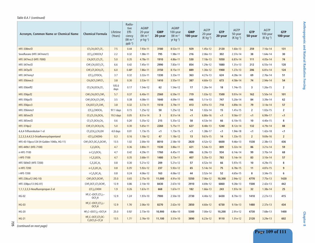
8
Anthropogenic and N
atural Radiative Forcing Chapter 8
735
Acronym, Common Name or Chemical Name Chemical FormulaLifetime(Years)
Radia-tiveEffi-
ciency(W m–2
ppb–1)
AGWP20-year(W m–2
yr kg–1)
GWP20-year
AGWP100-year(W m–2
yr kg–1)
GWP100-year
AGTP20-year(K kg–1)
GTP20-year
AGTP50-year(K kg–1)
GTP50-year
AGTP100-year(K kg–1)
GTP100-year
HFE-338mcf2 CF3CH2OCF2CF3 7.5 0.44 7.93e-11 3180 8.52e-11 929 1.45e-12 2120 1.60e-13 259 7.16e-14 131
Sevoflurane (HFE-347mmz1) (CF3)2CHOCH2F 2.2 0.32 1.98e-11 795 1.98e-11 216 2.06e-13 302 2.37e-14 38 1.64e-14 30
HFE-347mcc3 (HFE-7000) CH3OCF2CF2CF3 5.0 0.35 4.78e-11 1910 4.86e-11 530 7.18e-13 1050 6.87e-14 111 4.05e-14 74
HFE-347mcf2 CHF2CH2OCF2CF3 6.6 0.42 7.45e-11 2990 7.83e-11 854 1.29e-12 1880 1.31e-13 212 6.55e-14 120
HFE-347pcf2 CHF2CF2OCH2CF3 6.0 0.48h 7.86e-11 3150 8.15e-11 889 1.30e-12 1900 1.27e-13 206 6.81e-14 124
HFE-347mmy1 (CF3)2CFOCH3 3.7 0.32 3.32e-11 1330 3.33e-11 363 4.27e-13 624 4.28e-14 69 2.76e-14 51
HFE-356mec3 CH3OCF2CHFCF3 3.8 0.30 3.53e-11 1410 3.55e-11 387 4.60e-13 673 4.58e-14 74 2.94e-14 54
HFE-356mff2 CF3CH2OCH2CF3105.0 days
0.17 1.54e-12 62 1.54e-12 17 1.26e-14 18 1.74e-15 3 1.26e-15 2
HFE-356pcf2 CHF2CH2OCF2CHF2 5.7 0.37 6.40e-11 2560 6.59e-11 719 1.03e-12 1500 9.97e-14 162 5.50e-14 101
HFE-356pcf3 CHF2OCH2CF2CHF2 3.5 0.38 4.08e-11 1640 4.09e-11 446 5.11e-13 747 5.20e-14 84 3.39e-14 62
HFE-356pcc3 CH3OCF2CF2CHF2 3.8 0.32 3.77e-11 1510 3.79e-11 413 4.91e-13 718 4.89e-14 79 3.14e-14 57
HFE-356mmz1 (CF3)2CHOCH3 97.1 days 0.15 1.25e-12 50 1.25e-12 14 1.02e-14 15 1.41e-15 2 1.02e-15 2
HFE-365mcf3 CF3CF2CH2OCH3 19.3 days 0.05 8.51e-14 3 8.51e-14 <1 6.80e-16 <1 9.56e-17 <1 6.99e-17 <1
HFE-365mcf2 CF3CF2OCH2CH3 0.6 0.26i 5.35e-12 215 5.35e-12 58 4.53e-14 66 6.10e-15 10 4.40e-15 8
HFE-374pc2 CHF2CF2OCH2CH3 5.0 0.30 5.65e-11 2260 5.75e-11 627 8.48e-13 1240 8.12e-14 132 4.79e-14 88
4,4,4-Trifluorobutan-1-ol CF3(CH2)2CH2OH 4.0 days 0.01 1.73e-15 <1 1.73e-15 <1 1.38e-17 <1 1.94e-18 <1 1.42e-18 <1
2,2,3,3,4,4,5,5-Octafluorocyclopentanol -(CF2)4CH(OH)- 0.3 0.16 1.18e-12 47 1.18e-12 13 9.67e-15 14 1.33e-15 2 9.69e-16 2
HFE-43-10pccc124 (H-Galden 1040x, HG-11) CHF2OCF2OC2F4OCHF2 13.5 1.02 2.00e-10 8010 2.58e-10 2820 4.52e-12 6600 9.46e-13 1530 2.38e-13 436
HFE-449s1 (HFE-7100) C4F9OCH3 4.7 0.36 3.80e-11 1530 3.86e-11 421 5.54e-13 809 5.32e-14 86 3.21e-14 59
n-HFE-7100 n-C4F9OCH3 4.7 0.42 4.39e-11 1760 4.45e-11 486 6.39e-13 934 6.14e-14 99 3.70e-14 68
i-HFE-7100 i-C4F9OCH3 4.7 0.35 3.68e-11 1480 3.73e-11 407 5.35e-13 783 5.14e-14 83 3.10e-14 57
HFE-569sf2 (HFE-7200) C4F9OC2H5 0.8 0.30 5.21e-12 209 5.21e-12 57 4.52e-14 66 5.97e-15 10 4.29e-15 8
n-HFE-7200 n-C4F9OC2H5 0.8 0.35i 5.92e-12 237 5.92e-12 65 5.14e-14 75 6.78e-15 11 4.87e-15 9
i-HFE-7200 i-C4F9OC2H5 0.8 0.24 4.06e-12 163 4.06e-12 44 3.52e-14 52 4.65e-15 8 3.34e-15 6
HFE-236ca12 (HG-10) CHF2OCF2OCHF2 25.0 0.65 2.75e-10 11,000 4.91e-10 5350 7.06e-12 10,300 2.94e-12 4770 7.75e-13 1420
HFE-338pcc13 (HG-01) CHF2OCF2CF2OCHF2 12.9 0.86 2.10e-10 8430 2.67e-10 2910 4.69e-12 6860 9.28e-13 1500 2.42e-13 442
1,1,1,3,3,3-Hexafluoropropan-2-ol (CF3)2CHOH 1.9 0.26 1.67e-11 668 1.67e-11 182 1.66e-13 243 1.97e-14 32 1.38e-14 25
HG-02HF2C–(OCF2CF2)2–
OCF2H12.9 1.24i 1.97e-10 7900 2.50e-10 2730 4.40e-12 6430 8.70e-13 1410 2.27e-13 415
HG-03HF2C–(OCF2CF2)3–
OCF2H12.9 1.76i 2.06e-10 8270 2.62e-10 2850 4.60e-12 6730 9.10e-13 1480 2.37e-13 434
HG-20 HF2C–(OCF2)2–OCF2H 25.0 0.92i 2.73e-10 10,900 4.86e-10 5300 7.00e-12 10,200 2.91e-12 4730 7.68e-13 1400
HG-21HF2C–OCF2CF2OC-
F2OCF2O–CF2H13.5 1.71i 2.76e-10 11,100 3.57e-10 3890 6.23e-12 9110 1.31e-12 2120 3.29e-13 602
(continued on next page)
Table 8.A.1 (continued)
Page 109 of 111

8
Chapter 8 A
nthropogenic and Natural Radiative Forcing
736
Acronym, Common Name or Chemical Name Chemical FormulaLifetime(Years)
Radia-tiveEffi-
ciency(W m–2
ppb–1)
AGWP20-year(W m–2
yr kg–1)
GWP20-year
AGWP100-year(W m–2
yr kg–1)
GWP100-year
AGTP20-year(K kg–1)
GTP20-year
AGTP50-year(K kg–1)
GTP50-year
AGTP100-year(K kg–1)
GTP100-year
HG-30 HF2C–(OCF2)3–OCF2H 25.0 1.65i 3.77e-10 15,100 6.73e-10 7330 9.68e-12 14,100 4.03e-12 6530 1.06e-12 1940
1-Ethoxy-1,1,2,2,3,3,3-heptafluoropropane CF3CF2CF2OCH2CH3 0.8 0.28i 5.56e-12 223 5.56e-12 61 4.80e-14 70 6.36e-15 10 4.57e-15 8
Fluoroxene CF3CH2OCH=CH2 3.6 days 0.01i 4.97e-15 <1 4.97e-15 <1 3.95e-17 <1 5.58e-18 <1 4.08e-18 <1
1,1,2,2-Tetrafluoro-1-(fluoromethoxy)ethane CH2FOCF2CF2H 6.2 0.34i 7.68e-11 3080 7.99e-11 871 1.29e-12 1880 1.28e-13 207 6.68e-14 122
2-Ethoxy-3,3,4,4,5-pentafluorotetrahydro-2,5-bis[1,2,2,2-tetrafluoro-1-(trifluoromethyl)ethyl]-furan
C12H5F19O2 1.0 0.49j 5.09e-12 204 5.09e-12 56 4.53e-14 66 5.86e-15 10 4.19e-15 8
Fluoro(methoxy)methane CH3OCH2F 73.0 days 0.07g 1.15e-12 46 1.15e-12 13 9.34e-15 14 1.30e-15 2 9.46e-16 2
Difluoro(methoxy)methane CH3OCHF2 1.1 0.17g 1.32e-11 528 1.32e-11 144 1.18e-13 173 1.52e-14 25 1.08e-14 20
Fluoro(fluoromethoxy)methane CH2FOCH2F 0.9 0.19g 1.20e-11 479 1.20e-11 130 1.05e-13 153 1.37e-14 22 9.84e-15 18
Difluoro(fluoromethoxy)methane CH2FOCHF2 3.3 0.30g 5.65e-11 2260 5.66e-11 617 6.88e-13 1010 7.11e-14 115 4.69e-14 86
Trifluoro(fluoromethoxy)methane CH2FOCF3 4.4 0.33g 6.82e-11 2730 6.89e-11 751 9.59e-13 1400 9.27e-14 150 5.72e-14 105
HG’-01 CH3OCF2CF2OCH3 2.0 0.29 2.03e-11 815 2.03e-11 222 2.06e-13 301 2.42e-14 39 1.68e-14 31
HG’-02 CH3O(CF2CF2O)2CH3 2.0 0.56 2.16e-11 868 2.16e-11 236 2.19e-13 320 2.57e-14 42 1.79e-14 33
HG’-03 CH3O(CF2CF2O)3CH3 2.0 0.76 2.03e-11 812 2.03e-11 221 2.05e-13 299 2.41e-14 39 1.67e-14 31
HFE-329me3 CF3CFHCF2OCF3 40.0 0.48 1.79e-10 7170 4.17e-10 4550 4.85e-12 7090 2.89e-12 4690 1.12e-12 2040
3,3,4,4,5,5,6,6,7,7,7-Undecafluoroheptan-1-ol CF3(CF2)4CH2CH2OH 20.0 days 0.06 3.91e-14 2 3.91e-14 <1 3.12e-16 <1 4.39e-17 <1 3.21e-17 <1
3,3,4,4,5,5,6,6,7,7,8,8,9,9,9-Pentadecafluorononan-1-ol CF3(CF2)6CH2CH2OH 20.0 days 0.07 3.00e-14 1 3.00e-14 <1 2.40e-16 <1 3.37e-17 <1 2.46e-17 <1
3,3,4,4,5,5,6,6,7,7,8,8,9,9,10,10,11,11,11-Non-adecafluoroundecan-1-ol
CF3(CF2)8CH2CH2OH 20.0 days 0.05 1.72e-14 <1 1.72e-14 <1 1.37e-16 <1 1.93e-17 <1 1.41e-17 <1
2-Chloro-1,1,2-trifluoro-1-methoxyethane CH3OCF2CHFCl 1.4 0.21 1.12e-11 449 1.12e-11 122 1.05e-13 153 1.31e-14 21 9.24e-15 17
PFPMIE (perfluoropolymethylisopropyl ether)CF3OCF(CF3)CF2OCF2OCF3
800.0 0.65 1.87e-10 7500 8.90e-10 9710 5.52e-12 8070 6.11e-12 9910 6.15e-12 11,300
HFE-216 CF3OCF=CF2 8.4 days 0.02 1.92e-14 <1 1.92e-14 <1 1.53e-16 <1 2.15e-17 <1 1.58e-17 <1
Trifluoromethyl formate HCOOCF3 3.5 0.31i 5.37e-11 2150 5.39e-11 588 6.73e-13 984 6.85e-14 111 4.47e-14 82
Perfluoroethyl formate HCOOCF2CF3 3.5 0.44i 5.30e-11 2130 5.32e-11 580 6.64e-13 971 6.76e-14 110 4.41e-14 81
Perfluoropropyl formate HCOOCF2CF2CF3 2.6 0.50i 3.45e-11 1380 3.45e-11 376 3.80e-13 555 4.19e-14 68 2.85e-14 52
Perfluorobutyl formate HCOOCF2CF2CF2CF3 3.0 0.56i 3.59e-11 1440 3.59e-11 392 4.19e-13 613 4.45e-14 72 2.97e-14 54
2,2,2-Trifluoroethyl formate HCOOCH2CF3 0.4 0.16i 3.07e-12 123 3.07e-12 33 2.55e-14 37 3.48e-15 6 2.52e-15 5
3,3,3-Trifluoropropyl formate HCOOCH2CH2CF3 0.3 0.13i 1.60e-12 64 1.60e-12 17 1.31e-14 19 1.80e-15 3 1.31e-15 2
1,2,2,2-Tetrafluoroethyl formate HCOOCHFCF3 3.2 0.35i 4.30e-11 1720 4.31e-11 470 5.17e-13 755 5.39e-14 87 3.57e-14 65
1,1,1,3,3,3-Hexafluoropropan-2-yl formate HCOOCH(CF3)2 3.2 0.33i 3.05e-11 1220 3.05e-11 333 3.66e-13 535 3.81e-14 62 2.53e-14 46
Perfluorobutyl acetate CH3COOCF2CF2CF2CF3 21.9 days 0.12i 1.52e-13 6 1.52e-13 2 1.21e-15 2 1.71e-16 <1 1.25e-16 <1
Perfluoropropyl acetate CH3COOCF2CF2CF3 21.9 days 0.11i 1.59e-13 6 1.59e-13 2 1.27e-15 2 1.78e-16 <1 1.30e-16 <1
Perfluoroethyl acetate CH3COOCF2CF3 21.9 days 0.10i 1.89e-13 8 1.89e-13 2 1.51e-15 2 2.12e-16 <1 1.55e-16 <1
Trifluoromethyl acetate CH3COOCF3 21.9 days 0.07i 1.90e-13 8 1.90e-13 2 1.52e-15 2 2.14e-16 <1 1.56e-16 <1
(continued on next page)
Table 8.A.1 (continued)
Page 110 of 111

8
Anthropogenic and N
atural Radiative Forcing Chapter 8
737
Acronym, Common Name or Chemical Name Chemical FormulaLifetime(Years)
Radia-tiveEffi-
ciency(W m–2
ppb–1)
AGWP20-year(W m–2
yr kg–1)
GWP20-year
AGWP100-year(W m–2
yr kg–1)
GWP100-year
AGTP20-year(K kg–1)
GTP20-year
AGTP50-year(K kg–1)
GTP50-year
AGTP100-year(K kg–1)
GTP100-year
Methyl carbonofluoridate FCOOCH3 1.8 0.07i 8.74e-12 350 8.74e-12 95 8.60e-14 126 1.03e-14 17 7.21e-15 13
1,1-Difluoroethyl carbonofluoridate FCOOCF2CH3 0.3 0.17i 2.46e-12 99 2.46e-12 27 2.02e-14 30 2.78e-15 5 2.02e-15 4
1,1-Difluoroethyl 2,2,2-trifluoroacetate CF3COOCF2CH3 0.3 0.27i 2.83e-12 113 2.83e-12 31 2.33e-14 34 3.20e-15 5 2.32e-15 4
Ethyl 2,2,2-trifluoroacetate CF3COOCH2CH3 21.9 days 0.05i 1.26e-13 5 1.26e-13 1 1.00e-15 1 1.41e-16 <1 1.03e-16 <1
2,2,2-Trifluoroethyl 2,2,2-trifluoroacetate CF3COOCH2CF3 54.8 days 0.15i 6.27e-13 25 6.27e-13 7 5.06e-15 7 7.07e-16 1 5.15e-16 <1
Methyl 2,2,2-trifluoroacetate CF3COOCH3 0.6 0.18i 4.80e-12 192 4.80e-12 52 4.08e-14 60 5.47e-15 9 3.95e-15 7
Methyl 2,2-difluoroacetate HCF2COOCH3 40.1 days 0.05i 3.00e-13 12 3.00e-13 3 2.41e-15 4 3.38e-16 <1 2.47e-16 <1
Difluoromethyl 2,2,2-trifluoroacetate CF3COOCHF2 0.3 0.24i 2.48e-12 99 2.48e-12 27 2.04e-14 30 2.81e-15 5 2.04e-15 4
2,2,3,3,4,4,4-Heptafluorobutan-1-ol C3F7CH2OH 0.6 0.20 3.10e-12 124 3.10e-12 34 2.61e-14 38 3.52e-15 6 2.55e-15 5
1,1,2-Trifluoro-2-(trifluoromethoxy)-ethane CHF2CHFOCF3 9.8 0.35 9.91e-11 3970 1.14e-10 1240 2.03e-12 2960 2.88e-13 467 9.74e-14 178
1-Ethoxy-1,1,2,3,3,3-hexafluoropropane CF3CHFCF2OCH2CH3 0.4 0.19 2.14e-12 86 2.14e-12 23 1.77e-14 26 2.43e-15 4 1.76e-15 3
1,1,1,2,2,3,3-Heptafluoro-3-(1,2,2,2-tetrafluoroethoxy)-propane
CF3CF2CF2OCHFCF3 67.0 0.58 1.98e-10 7940 5.95e-10 6490 5.57e-12 8140 4.29e-12 6960 2.39e-12 4380
2,2,3,3-Tetrafluoro-1-propanol CHF2CF2CH2OH 91.3 days 0.11 1.19e-12 48 1.19e-12 13 9.72e-15 14 1.35e-15 2 9.79e-16 2
2,2,3,4,4,4-Hexafluoro-1-butanol CF3CHFCF2CH2OH 94.9 days 0.19 1.56e-12 63 1.56e-12 17 1.27e-14 19 1.76e-15 3 1.28e-15 2
2,2,3,3,4,4,4-Heptafluoro-1-butanol CF3CF2CF2CH2OH 0.3 0.16 1.49e-12 60 1.49e-12 16 1.23e-14 18 1.69e-15 3 1.23e-15 2
1,1,2,2-Tetrafluoro-3-methoxy-propane CHF2CF2CH2OCH3 14.2 days 0.03 4.82e-14 2 4.82e-14 <1 3.84e-16 <1 5.41e-17 <1 3.96e-17 <1
perfluoro-2-methyl-3-pentanone CF3CF2C(O)CF(CF3)2 7.0 days 0.03 9.14e-15 <1 9.14e-15 <1 7.27e-17 <1 1.03e-17 <1 7.51e-18 <1
3,3,3-Trifluoro-propanal CF3CH2CHO 2.0 days 0.004 9.86e-16 <1 9.86e-16 <1 7.84e-18 <1 1.11e-18 <1 8.10e-19 <1
2-Fluoroethanol CH2FCH2OH 20.4 days 0.02 8.07e-14 3 8.07e-14 <1 6.45e-16 <1 9.07e-17 <1 6.63e-17 <1
2,2-Difluoroethanol CHF2CH2OH 40.0 days 0.04 2.78e-13 11 2.78e-13 3 2.23e-15 3 3.12e-16 <1 2.28e-16 <1
2,2,2-Trifluoroethanol CF3CH2OH 0.3 0.10 1.83e-12 73 1.83e-12 20 1.50e-14 22 2.07e-15 3 1.50e-15 3
1,1’-Oxybis[2-(difluoromethoxy)-1,1,2,2-tetrafluoroethane HCF2O(CF2CF2O)2CF2H 26.0 1.15k 2.47e-10 9910 4.51e-10 4920 6.38e-12 9320 2.75e-12 4460 7.45e-13 1360
1,1,3,3,4,4,6,6,7,7,9,9,10,10,12,12-hexa-decafluoro-2,5,8,11-Tetraoxadodecane
HCF2O(CF2CF2O)3CF2H 26.0 1.43k 2.26e-10 9050 4.12e-10 4490 5.83e-12 8520 2.51e-12 4080 6.81e-13 1250
1,1,3,3,4,4,6,6,7,7,9,9,10,10,12,12,13,13,15,15-eico-safluoro-2,5,8,11,14-Pentaoxapentadecane
HCF2O(CF2CF2O)4CF2H 26.0 1.46k 1.83e-10 7320 3.33e-10 3630 4.71e-12 6880 2.03e-12 3300 5.50e-13 1010
Table 8.A.1 (continued)
Notes:
For CH4 we estimate an uncertainty of ±30% and ±40% for 20- and 100-year time horizon, respectively (for 90% uncertainty range). The uncertainty is dominated by AGWP for CO2 and indirect effects. The uncertainty in GWP for N2O is estimated to ±20% and ±30% for 20- and 100-year time horizon, with the largest contributions from CO2. The uncertainty in GWP for HFC-134a is estimated to ±25% and ±35% for 20- and 100-year time horizons while for CFC-11 the GWP the corresponding numbers are approximately ±20% and ±35% (not accounting for the indirect effects). For CFC-12 the corresponding numbers are ±20 and ±30. The uncertainties estimated for HFC-134a and CFC-11 are assessed as representative for most other gases with similar or longer lifetimes. For shorter-lived gases, the uncertainties will be larger. For GTP, few estimates are available in the literature. The uncertainty is assessed to be of the order of ±75% for the methane GTP100.
* No single lifetime can be given. The impulse response function for CO2 from Joos et al. (2013) has been used. See also Supplementary Material Section 8.SM.11.
† Perturbation lifetime is used in calculation of metrics, not the lifetime of the atmospheric burden.
(continued on next page)
Page 111 of 111