Embed Size (px)
Citation preview
NFPA 12
Standard on Carbon Dioxide
Extinguishing Systems
2005 Edition
NFPA, 1 Batterymarch Park, Quincy, MA 02169-7471 An International Codes and Standards Organization
Copyright National Fire Protection Association Provided by IHS under license with NFPA
Not for ResaleNo reproduction or networking permitted without license from IHS
--`,,,```-`-`,,`,,`,`,,`---

IMPORTANT NOTICES AND DISCLAIMERS CONCERNING NFPA DOCUMENTS
NOTICE AND DISCLAIMER OF LIABILITY CONCERNING THE USE OF NFPA DOCUMENTS
NFPA codes, standards, recommended practices, and guides, of which the document contained herein is one, are de-veloped through a consensus standards development process approved by the American National Standards Institute.This process brings together volunteers representing varied viewpoints and interests to achieve consensus on fire andother safety issues. While the NFPA administers the process and establishes rules to promote fairness in the develop-ment of consensus, it does not independently test, evaluate, or verify the accuracy of any information or the soundnessof any judgments contained in its codes and standards.
The NFPA disclaims liability for any personal injury, property or other damages of any nature whatsoever, whetherspecial, indirect, consequential or compensatory, directly or indirectly resulting from the publication, use of, or relianceon this document. The NFPA also makes no guaranty or warranty as to the accuracy or completeness of any informationpublished herein.
In issuing and making this document available, the NFPA is not undertaking to render professional or other servicesfor or on behalf of any person or entity. Nor is the NFPA undertaking to perform any duty owed by any person or entityto someone else. Anyone using this document should rely on his or her own independent judgment or, as appropriate,seek the advice of a competent professional in determining the exercise of reasonable care in any given circumstances.
The NFPA has no power, nor does it undertake, to police or enforce compliance with the contents of this document.Nor does the NFPA list, certify, test or inspect products, designs, or installations for compliance with this document.Any certification or other statement of compliance with the requirements of this document shall not be attributable tothe NFPA and is solely the responsibility of the certifier or maker of the statement.
Copyright National Fire Protection Association Provided by IHS under license with NFPA
Not for ResaleNo reproduction or networking permitted without license from IHS
--`,,,```-`-`,,`,,`,`,,`---

ADDITIONAL NOTICES AND DISCLAIMERS
Updating of NFPA Documents
Users of NFPA codes, standards, recommended practices, and guides should be aware thatthese documents may be superseded at any time by the issuance of new editions or may beamended from time to time through the issuance of Tentative Interim Amendments. An offi-cial NFPA document at any point in time consists of the current edition of the documenttogether with any Tentative Interim Amendments and any Errata then in effect. In order todetermine whether a given document is the current edition and whether it has been amendedthrough the issuance of Tentative Interim Amendments or corrected through the issuance ofErrata, consult appropriate NFPA publications such as the National Fire Codes® SubscriptionService, visit the NFPA website at www.nfpa.org, or contact the NFPA at the address listedbelow.
Interpretations of NFPA Documents
A statement, written or oral, that is not processed in accordance with Section 6 of the Reg-ulations Governing Committee Projects shall not be considered the official position of NFPAor any of its Committees and shall not be considered to be, nor be relied upon as, a FormalInterpretation.
Patents
The NFPA does not take any position with respect to the validity of any patent rightsasserted in connection with any items which are mentioned in or are the subject of NFPAcodes, standards, recommended practices, and guides, and the NFPA disclaims liability forthe infringement of any patent resulting from the use of or reliance on these documents.Users of these documents are expressly advised that determination of the validity of any suchpatent rights, and the risk of infringement of such rights, is entirely their own responsibility.
NFPA adheres to applicable policies of the American National Standards Institute withrespect to patents. For further information contact the NFPA at the address listed below.
Law and Regulations
Users of these documents should consult applicable federal, state, and local laws and reg-ulations. NFPA does not, by the publication of its codes, standards, recommended practices,and guides, intend to urge action that is not in compliance with applicable laws, and thesedocuments may not be construed as doing so.
Copyrights
This document is copyrighted by the NFPA. It is made available for a wide variety of bothpublic and private uses. These include both use, by reference, in laws and regulations, anduse in private self-regulation, standardization, and the promotion of safe practices andmethods. By making this document available for use and adoption by public authorities andprivate users, the NFPA does not waive any rights in copyright to this document.
Use of NFPA documents for regulatory purposes should be accomplished through adop-tion by reference. The term “adoption by reference” means the citing of title, edition, andpublishing information only. Any deletions, additions, and changes desired by the adoptingauthority should be noted separately in the adopting instrument. In order to assist NFPA infollowing the uses made of its documents, adopting authorities are requested to notify theNFPA (Attention: Secretary, Standards Council) in writing of such use. For technical assis-tance and questions concerning adoption of NFPA documents, contact NFPA at the addressbelow.
For Further Information
All questions or other communications relating to NFPA codes, standards, recommendedpractices, and guides and all requests for information on NFPA procedures governing itscodes and standards development process, including information on the procedures forrequesting Formal Interpretations, for proposing Tentative Interim Amendments, and forproposing revisions to NFPA documents during regular revision cycles, should be sent toNFPA headquarters, addressed to the attention of the Secretary, Standards Council, NFPA,1 Batterymarch Park, P.O. Box 9101, Quincy, MA 02269-9101.
For more information about NFPA, visit the NFPA website at www.nfpa.org.
Copyright National Fire Protection Association Provided by IHS under license with NFPA
Not for ResaleNo reproduction or networking permitted without license from IHS
--`,,,```-`-`,,`,,`,`,,`---

ttSs
2
S11Cp
md
c
12–1
Copyright National Fire Protection Association Provided by IHS under license with NFPANo reproduction or networking permitted without license fro
--`,,,```-`-`,,`,,`,`,,`---
Copyright © 2005, National Fire Protection Association, All Rights Reserved
NFPA 12
Standard on
Carbon Dioxide Extinguishing Systems
2005 Edition
This edition of NFPA 12, Standard on Carbon Dioxide Extinguishing Systems, was prepared byhe Technical Committee on Carbon Dioxide and acted on by NFPA at its November Associa-ion Technical Meeting held November 13–17, 2004, in Miami Beach, FL. It was issued by thetandards Council on January 14, 2005, with an effective date of February 7, 2005, and super-edes all previous editions.
This edition of NFPA 12 was approved as an American National Standard on February 7,005.
Origin and Development of NFPA 12Work on this standard was initiated in 1928 by the Committee on Manufacturing Risks and
pecial Hazards. The standard was first adopted in 1929 and was revised in 1933, 1939, 1940, 1941,942 (January and May), 1945, 1946, 1948, 1949, 1956, 1957, 1961, 1962, 1963, 1964, 1966, 1968,972, 1973, 1977, and 1980. Revisions adopted between 1945 and 1949 were proposed by theommittee on Special Extinguishing Systems, and those in 1956 and subsequent revisions wereroposed by the Committee on Carbon Dioxide. The standard was revised in 1985 and 1989.
The standard was completely rewritten for the 1993 revision to more clearly state the require-ents and to separate the mandatory requirements from the advisory text in an effort to make the
ocument more usable, enforceable, and adoptable.The standard was revised for the 1998 edition and again in 2000 in order to add a new
hapter for marine systems.The 2005 edition of this standard was revised with a focus on safety.
Not for Resalem IHS

12–2 CARBON DIOXIDE EXTINGUISHING SYSTEMS
2005 Ed
Copyright National Fire ProtectioProvided by IHS under license wNo reproduction or networking p
Technical Committee on Carbon Dioxide
James M. Rucci, ChairHarrington Group, Inc., GA [SE]
Ronald C. Adcock, Marsh USA Inc., AZ [I]Richard Bisterfeldt, Liberty Mutual Property, IL [I]
Rep. Alliance of American InsurersTodd A. Dillon, GE Global Asset Protection Services,OH [I]
Rep. GE Global Asset Protection ServicesRay Downey, Chemetron Fire Systems/WilliamsHoldings, OH [M]Dale R. Edlbeck, Tyco Fire & Security, WI [M]William S. Fink, The RJA Group, Inc., CO [SE]David M. Gough, Global Risk Consultants Corporation,CT [SE]Donald W. Hering, 3S Incorporated, OH [IM]William Matt Hogan, Duke Power Company, SC [U]
Rep. Edison Electric Institute
Alternates
Nonvoting
(Member Emeritus)
Mark T. Conroy, NFPA Staff Liaison
Tc
Na
Cn
ition
n Association ith NFPA
Not for Resaermitted without license from IHS
James L. Kidd, Hiller New England Fire Protection, Inc.,MA [IM]
Rep. Fire Suppression Systems AssociationGeorge E. Laverick, Underwriters Laboratories Inc.,IL [RT]Robert C. Merritt, FM Global, MA [I]
Rep. FM Global/FM Engineering & ResearchEarl D. Neargarth, Fike Corporation, MO [M]Timothy J. Sullivan, General Motors Corporation,MI [U]Klaus Wahle, U.S. Coast Guard, DC [E]Gregory G. Wilks, Nuclear Electric Insurance Limited,DE [I]Thomas J. Wysocki, Guardian Services, Inc., IL [SE]
Randall S. Chaney, Liberty Mutual Property, CA [I](Alt. to R. Bisterfeldt)
Anthony R. Cole, The RJA Group, Inc., CO [SE](Alt. to W. S. Fink)
Randall Eberly, U.S. Coast Guard Headquarters, DC [E](Alt. to K. Wahle)
Robert Kasiski, Factory Mutual Research Corporation,RI [I]
(Alt. to R. C. Merritt)Hendrik T. (Henk) Lammertink, Kidde-Fenwal, Inc.,MA [IM]
(Alt. to J. L. Kidd)
Norbert W. Makowka, National Association of FireEquipment Distributors, IL [IM]
(Alt. to NAFED Rep.)Bruce G. Scheiman, Chemetron Fire Systems/WilliamsHoldings, IL [M]
(Alt. to R. Downey)Michael D. Sides, GE Global Asset Protection Services,FL [I]
(Alt. to T. A. Dillon)Matthew D. Tennenbaum, Underwriters LaboratoriesInc., IL [RT]
(Alt. to G. E. Laverick)
Edward D. Leedy, Naperville, IL
--`,,,```-`-`,,`,,`,`,,`---
his list represents the membership at the time the Committee was balloted on the final text of this edition. Since that time,hanges in the membership may have occurred. A key to classifications is found at the back of the document.
OTE: Membership on a committee shall not in and of itself constitute an endorsement of the Association orny document developed by the committee on which the member serves.
ommittee Scope: This Committee shall have primary responsibility for documents on the installation, mainte-ance, and use of carbon dioxide systems for fire protection.
le

12–3CONTENTS
Copyright National Fire PrProvided by IHS under liceNo reproduction or networ
Contents
Chapter 1 Administration ................................. 12– 41.1 Scope .................................................. 12– 41.2 Purpose ............................................... 12– 41.3 Retroactivity .......................................... 12– 41.4 Units ................................................... 12– 4
Chapter 2 Referenced Publications .................... 12– 42.1 General ............................................... 12– 42.2 NFPA Publications .................................. 12– 42.3 Other Publications ................................. 12– 4
Chapter 3 Definitions ...................................... 12– 53.1 General ............................................... 12– 53.2 NFPA Official Definitions ......................... 12– 53.3 General Definitions ................................ 12– 53.4 Special Definitions ................................. 12– 5
Chapter 4 General Information ......................... 12– 64.1 Restrictions for Normally Occupied
Enclosures ............................................ 12– 64.2 Carbon Dioxide Use and Limitations .......... 12– 64.3 Personnel Safety .................................... 12– 64.4 Specifications, Plans, and Approvals ........... 12– 94.5 Detection, Actuation, and Control ............. 12–104.6 Carbon Dioxide Supply ........................... 12–124.7 Distribution Systems ............................... 12–134.8 Inspection, Maintenance, and
Instruction ........................................... 12–15
Chapter 5 Total Flooding Systems ...................... 12–165.1 General Information ............................... 12–165.2 Hazard Specifications ............................. 12–165.3 Carbon Dioxide Requirements for
Surface Fires ......................................... 12–165.4 Carbon Dioxide Requirements for
Deep-Seated Fires .................................. 12–185.5 Distribution System ................................ 12–195.6 Venting Consideration ............................ 12–19
Chapter 6 Local Application Systems .................. 12–206.1 General Information ............................... 12–206.2 Hazard Specifications ............................. 12–206.3 Carbon Dioxide Requirements .................. 12–206.4 Rate-by-Area Method .............................. 12–20
otection Association nse with NFPA
Not for Resaking permitted without license from IHS
--`,,,```-`-`,,`,,`,`,,`---
6.5 Rate-by-Volume Method ........................... 12–216.6 Distribution System ................................ 12–22
Chapter 7 Hand Hose Line Systems .................... 12–227.1 General Information ............................... 12–227.2 Hazard Specifications ............................. 12–227.3 Location and Spacing ............................. 12–227.4 Carbon Dioxide Requirements .................. 12–227.5 Equipment Specifications ........................ 12–227.6 Training .............................................. 12–23
Chapter 8 Standpipe Systems and MobileSupply ........................................... 12–23
8.1 General Information ............................... 12–238.2 Hazard Specifications ............................. 12–238.3 Standpipe Requirements ......................... 12–238.4 Mobile Supply Requirements .................... 12–238.5 Training .............................................. 12–23
Chapter 9 Marine Systems ................................ 12–239.1 Special Definitions ................................. 12–239.2 General ............................................... 12–239.3 System Requirements .............................. 12–239.4 Inspection and Maintenance .................... 12–25
Annex A Explanatory Material ........................... 12–25
Annex B Examples of Hazard Protection ............. 12–37
Annex C Pipe and Orifice Size Determination ...... 12–40
Annex D Total Flooding Systems ........................ 12–45
Annex E Surface Fires ..................................... 12–47
Annex F Local Application Carbon DioxideSystems ............................................ 12–48
Annex G General Information on CarbonDioxide ........................................... 12–50
Annex H Informational References .................... 12–51
Index ............................................................. 12–53
2005 Edition
le

12–4 CARBON DIOXIDE EXTINGUISHING SYSTEMS
Copyright National FiProvided by IHS undeNo reproduction or ne
NFPA 12
Standard on
Carbon Dioxide Extinguishing Systems
2005 Edition
IMPORTANT NOTE: This NFPA document is made available foruse subject to important notices and legal disclaimers. These noticesand disclaimers appear in all publications containing this documentand may be found under the heading “Important Notices and Dis-claimers Concerning NFPA Documents.” They can also be obtainedon request from NFPA or viewed at www.nfpa.org/disclaimers.
NOTICE: An asterisk (*) following the number or letterdesignating a paragraph indicates that explanatory materialon the paragraph can be found in Annex A.
A reference in brackets [ ] following a section or paragraphindicates material that has been extracted from another NFPAdocument.As an aid to the user, the complete title and edition ofthe source documents for mandatory extracts are given in Chap-ter 2 and those for nonmandatory extracts are given in Annex H.Editorial changes to extracted material consist of revising refer-ences to an appropriate division in this document or the inclu-sion of the document number with the division number whenthe reference is to the original document. Requests for interpre-tations or revisions of extracted text shall be sent to the technicalcommittee responsible for the source document.
Information on referenced publications can be found inChapter 2 and Annex H.
Chapter 1 Administration
1.1* Scope.
1.1.1 This standard contains minimum requirements for car-bon dioxide fire-extinguishing systems.
1.1.2 It includes only the necessary essentials to make the stan-dard workable in the hands of those skilled in this field.
1.2 Purpose.
1.2.1 This standard is prepared for the use and guidance ofthose charged with the purchasing, designing, installing, test-ing, inspecting, approving, listing, operating, or maintainingof carbon dioxide fire-extinguishing systems, in order that suchequipment will function as intended throughout its life.
1.2.2 Nothing in this standard is intended to restrict newtechnologies or alternative arrangements, provided the levelof safety prescribed by the standard is not lowered.
1.2.3 Only those with the proper training and experienceshall design, install, inspect, and maintain this equipment.
1.3 Retroactivity. The provisions of this standard reflect a con-sensus of what is necessary to provide an acceptable degree ofprotection from the hazards addressed in this standard at thetime the standard was issued.
1.3.1 Unless otherwise specified, the provisions of this stan-dard shall not apply to facilities, equipment, structures, or in-stallations that existed or were approved for construction orinstallation prior to the effective date of the standard. Where
--`,,,```-`-`,,`,,`,`,,`---
specified, the provisions of this standard will be retroactive.
2005 Edition
re Protection Association r license with NFPA
Not fortworking permitted without license from IHS
1.3.2 In those cases where the authority having jurisdictiondetermines that the existing situation presents an unaccept-able degree of risk, the authority having jurisdiction shall bepermitted to apply retroactively any portions of this standarddeemed appropriate.
1.3.3 The retroactive requirements of this standard shall bepermitted to be modified if their application clearly would beimpractical in the judgment of the authority having jurisdic-tion and only where it is clearly evident that a reasonable de-gree of safety is provided.
1.3.4 Existing systems shall be upgraded to meet the require-ments for safety signs in 4.3.2, lock-out valves in 4.3.3.6 and4.3.3.6.1, and pneumatic time delays and pneumatic predis-charge alarms in 4.5.6.1.
1.3.5* These upgrades shall be completed by August 7, 2006.
1.4* Units. Metric units of measurement in this standard are inaccordance with the modernized metric system known as the In-ternational System of Units (SI), as shown in Table A.1.4.
Chapter 2 Referenced Publications
2.1 General. The documents or portions thereof listed in thischapter are referenced within this standard and shall be con-sidered part of the requirements of this document.
2.2 NFPA Publications. National Fire Protection Association,1 Batterymarch Park, Quincy, MA 02169-7471.
NFPA 70, National Electrical Code®, 2005 edition.NFPA 72®, National Fire Alarm Code®, 2002 edition.
2.3 Other Publications.
2.3.1 ANSI Publications. American National Standards Insti-tute, Inc., 25 West 43rd Street, 4th Floor, New York, NY 10036.
ANSI/IEEE C 2, National Electrical Safety Code, 2002.
MNBV/ANSI Z535, Standard for Environmental and FacilitySafety Signs, 2002.
2.3.2 API Publication. American Petroleum Institute, 1220 LStreet, NW, Washington, DC 20005-4070.
API-ASME Code for Unfired Pressure Vessels for Petroleum Liquidsand Gases, Pre–July 1, 1961.
2.3.3 ASME Publication. American Society of MechanicalEngineers, Three Park Avenue, New York, NY 10016-5990.
ASME B31.1, Power Piping Code, 2001.
2.3.4 ASTM Publications. American Society for Testing andMaterials, 100 Barr Harbor Drive, West Conshohocken, PA19428-2959.
ASTM A 53, Standard Specification for Pipe, Steel, Black andHot-Dipped, Zinc-Coated, Welded and Seamless, 2004.
ASTM A 106, Standard Specification for Seamless Carbon SteelPipe for High-Temperature Service, 2002.
ASTM A 120, Specification for Welded and Steel Pipe, 1996.
ASTM A 182, Standard Specification for Forged or Rolled Alloy-Steel Pipe Flanges, Forged Fittings, and Valves and Parts for High-
Temperature Service, 2004.Resale

12–5DEFINITIONS
Copyright National Fire PrProvided by IHS under liceNo reproduction or networ
2.3.5 CGA Publication. Compressed Gas Association, 4221Walney Road, 5th Floor, Chantilly, VA 20151-2923.
CGA G6.2, Commodity Specification for Carbon Dioxide, 2004.
2.3.6 CSA Publication. Canadian Standards Association,5060 Spectrum Way, Mississauga, Ontario L4W 5N6, Canada.
CSA C22.1, Canadian Electrical Code, 2002.
2.3.7 U.S. Government Publications. U.S. Government Print-ing Office, Washington, DC 20402.
Title 46, Code of Federal Regulations, Part 58.20.
Title 46, Code of Federal Regulations, Part 72.
Title 49, Code of Federal Regulations, Parts 171–190 (De-partment of Transportation).
Bureau of Mines Bulletins 503 and 627, Limits of Flammabil-ity of Gases and Vapors (Department of Transportation), 1962.
Chapter 3 Definitions
3.1 General. The definitions contained in this chapter shallapply to the terms used in this standard. Where terms are notdefined in this chapter or within another chapter, they shallbe defined using their ordinarily accepted meanings withinthe context in which they are used. Merriam-Webster’s CollegiateDictionary, 11th edition, shall be the source for the ordinarilyaccepted meaning.
3.2 NFPA Official Definitions.
3.2.1* Approved. Acceptable to the authority having jurisdic-tion.
3.2.2* Authority Having Jurisdiction (AHJ). An organization,office, or individual responsible for enforcing the require-ments of a code or standard, or for approving equipment,materials, an installation, or a procedure.
3.2.3 Labeled. Equipment or materials to which has been at-tached a label, symbol, or other identifying mark of an organiza-tion that is acceptable to the authority having jurisdiction andconcerned with product evaluation, that maintains periodic in-spection of production of labeled equipment or materials, andby whose labeling the manufacturer indicates compliance withappropriate standards or performance in a specified manner.
3.2.4* Listed. Equipment, materials, or services included in alist published by an organization that is acceptable to the au-thority having jurisdiction and concerned with evaluation ofproducts or services, that maintains periodic inspection ofproduction of listed equipment or materials or periodic evalu-ation of services, and whose listing states that either the equip-ment, material, or service meets appropriate designated stan-dards or has been tested and found suitable for a specifiedpurpose.
3.2.5 Shall. Indicates a mandatory requirement.
3.2.6 Should. Indicates a recommendation or that which isadvised but not required.
3.2.7 Standard. A document, the main text of which containsonly mandatory provisions using the word “shall” to indicaterequirements and which is in a form generally suitable formandatory reference by another standard or code or for adop-
tion into law. Nonmandatory provisions shall be located in anotection Association nse with NFPA
Not for Resaking permitted without license from IHS
--`,,,```-`-`,,`,,`,`,,`---
appendix or annex, footnote, or fine-print note and are not tobe considered a part of the requirements of a standard.
3.3 General Definitions.
3.3.1 Alarms and Indicators. Any device capable of providingaudible, visual, or olfactory indication.
3.3.2 Inspection. A visual examination of a system or portionthereof to verify that it appears to be in operating conditionand is free of physical damage. [820, 2003]
3.3.3 Lock-Out. A manually operated valve in the dischargepipe between the nozzles and the supply, which can be lockedin the closed position to prevent flow of carbon dioxide to theprotected area.
3.3.4 Maintenance. Work performed to ensure that equipmentoperates as directed by the manufacturer. [10, 2002]
3.3.5 Normally Occupied. An enclosure where, under normalcircumstances, persons are present.
3.3.6* Normally Unoccupied. An area or space not normallyoccupied by people but could be entered occasionally for briefperiods.
3.3.7 Occupiable. See 3.3.5, Normally Occupied.
3.3.8 Pressure.
3.3.8.1* High Pressure. Indicates that the carbon dioxide isstored in pressure containers at ambient temperatures.
3.3.8.2* Low Pressure. Indicates that the carbon dioxide isstored in pressure containers at a controlled low tempera-ture of 0°F (−18°C).
3.3.9 Standpipe System and Mobile Supply. A system consist-ing of a mobile supply of carbon dioxide, designed to bequickly moved into position and connected to a system offixed piping, supplying fixed nozzles or hose lines or both thatare designed for either total flooding or local application.
3.3.10 System.
3.3.10.1 Hand Hose Line System. A hose and nozzle assem-bly connected by fixed piping or connected directly to asupply of extinguishing agent. [122, 2004]
3.3.10.2 Local Application System. A system consisting of asupply of extinguishing agent arranged to discharge di-rectly on the burning material.
3.3.10.3* Pre-Engineered System. A system that has prede-termined flow rates, nozzle placement, and quantities ofcarbon dioxide and that incorporates specific nozzles andmethods of application that can differ from those detailedelsewhere in this standard and those that are listed by atesting laboratory.
3.3.10.4 Total Flooding System. A system consisting of a sup-ply of carbon dioxide arranged to discharge into, and fill tothe proper concentration, an enclosed space or enclosurearound the hazard.
3.3.11 Unoccupiable. An enclosure that cannot be occupieddue to dimensional or other physical constraints.
3.4 Special Definitions.
3.4.1 Marine Systems. Systems installed on ships, barges, off-
shore platforms, motorboats, and pleasure craft.2005 Edition
le

12–6 CARBON DIOXIDE EXTINGUISHING SYSTEMS
Copyright National FiProvided by IHS undeNo reproduction or ne
--`,,,```-`-`,,`,,`,`,,`---
3.4.2 Space.
3.4.2.1 Cargo Space. A space for the carriage or storage ofitems or products that are transported by the vessel.
3.4.2.2 Electrical Equipment Space. A space containing elec-trical propulsion, power generating, or power distributionequipment.
3.4.2.3 Machinery Space. A space that contains mechanicalequipment for handling, pumping, or transferring flam-mable or combustible liquids as a fuel.
3.4.2.4 Vehicle Space. A space that is designed for the car-riage of automobiles or other self-propelled vehicles.
Chapter 4 General Information
4.1 Restrictions for Normally Occupied Enclosures.
4.1.1* Carbon dioxide total flooding fire-extinguishing sys-tems shall not be installed in normally occupied enclosuresexcept as permitted in 4.1.2 through 4.1.4.
4.1.2 New Installations. Total flooding carbon dioxide sys-tems shall be permitted to be installed in normally occupiedenclosures where there are no suitable fire-extinguishingagents that can be used to provide an equivalent level of fireprotection to that of carbon dioxide.
4.1.2.1 If it is determined that carbon dioxide is be used for agiven application, the designer/installer shall provide sup-porting documentation to the authority having jurisdiction toverify that carbon dioxide is the most appropriate fire suppres-sion agent for the application.
4.1.3 Marine Applications. Manually operated total floodingmarine systems shall be permitted to be installed in normallyoccupied enclosures equipped with the following:
(1) System lock-out valves specified in 4.5.5(2) Pneumatic predischarge alarms and pneumatic time de-
lays specified in 9.3.3.5(3) Two independent, manually operated system discharge con-
trol valves to actuate the carbon dioxide system as specifiedin 9.3.3
4.1.4 Existing Systems. Existing total flooding carbon dioxidesystems shall be permitted in normally occupied enclosuresequipped with system lock-out valves, pneumatic predischargealarms, and pneumatic time delays specified in 4.5.6.
4.2 Carbon Dioxide Use and Limitations. See also Annex G.
4.2.1* Carbon dioxide fire-extinguishing systems protecting ar-eas where explosive atmospheres could exist shall utilize metalnozzles, and the entire system shall be grounded.
4.2.2 In addition, objects exposed to discharge from carbondioxide nozzles shall be grounded to dissipate possible electro-static charges.
4.3* Personnel Safety.
4.3.1* Hazards to Personnel.
4.3.1.1 Consideration shall be given to the possibility of car-bon dioxide drifting and settling into adjacent places outside
the protected space. (See 4.3.1.3.)2005 Edition
re Protection Association r license with NFPA
Not fortworking permitted without license from IHS
4.3.1.2 Consideration shall also be given to where the carbondioxide can migrate or collect in the event of a discharge froma safety relief device of a storage container.
4.3.1.3* In any use of carbon dioxide, consideration shall begiven to the possibility that personnel could be trapped in orenter into an atmosphere made hazardous by a carbon diox-ide discharge.
4.3.1.3.1 Safeguards shall be provided to ensure promptevacuation, to prevent entry into such atmospheres as de-scribed in 4.3.1.3, and to provide means for prompt rescue ofany trapped personnel.
4.3.1.3.2 Personnel training shall be provided.
4.3.2 Signs.
4.3.2.1 Warning signs shall be affixed in a conspicuous loca-tion in every protected space; at every entrance to protectedspaces; in spaces near the protected spaces where it is deter-mined that carbon dioxide could migrate, creating a hazard topersonnel; and at each entrance to carbon dioxide storagerooms and where carbon dioxide can migrate or collect in theevent of a discharge from a safety device of a storage container.
4.3.2.2 For all new system installations, the safety sign format,color, letter style of signal words, message panel lettering, let-tering size, and the safety provisions of symbols shall be inaccordance with MNBV/ANSI Z535, Standard for Environmen-tal and Facility Safety Signs.
4.3.2.3 Safety signs and message wording shall be providedusing a three-panel format as follows:
4.3.2.3.1 The sign in Figure 4.3.2.3.1 shall be used in everyprotected space.
4.3.2.3.2 The sign in Figure 4.3.2.3.2 shall be used at everyentrance to protected space.
4.3.2.3.3 The sign in Figure 4.3.2.3.3 shall be used at everyentrance to protected space for systems provided with a win-tergreen odorizer.
4.3.2.3.4 The sign in Figure 4.3.2.3.4 shall be used in everynearby space where carbon dioxide could accumulate to haz-ardous levels.
4.3.2.3.5 The sign in Figure 4.3.2.3.5 shall be used outside
Carbon dioxide gascan cause injury or death.
When alarm operates,vacate immediately.
WARNING
FIGURE 4.3.2.3.1 Sign in Every Protected Space.
each entrance to carbon dioxide storage rooms.
Resale

12–7GENERAL INFORMATION
Copyright National Fire PrProvided by IHS under liceNo reproduction or networ
4.3.2.3.6 Signs for Manual Operation.
4.3.2.3.6.1 Warning signs shall be placed at every locationwhere manual operation of the system can occur.
4.3.2.3.6.2 The sign in Figure 4.3.2.3.6.2 shall be used at eachmanual actuation station.
4.3.2.4 For existing system installations that have existingsigns that meet the requirements of 4.3.2.1, the signage shallbe considered to be acceptable if the facility has an effectivetraining program in place covering all suppression system–
Carbon dioxide gascan cause injury or death.
When alarm operates,do not enter
until ventilated.
WARNING
FIGURE 4.3.2.3.2 Sign at Every Entrance to Protected Space.
Carbon dioxide gascan cause injury or death.When alarm operates or
wintergreen scent isdetected, do not enter
until ventilated.
WARNING
FIGURE 4.3.2.3.3 Sign at Every Entrance to Protected Spacefor Systems Provided with a Wintergreen Odorizer.
Carbon dioxide gas dischargeinto nearby space can collecthere. When alarm operates,
vacate immediately.Carbon dioxide gas
can cause injury or death.
CAUTION
FIGURE 4.3.2.3.4 Sign in Every Nearby Space Where CarbonDioxide Can Accumulate to Hazardous Levels.
related signage, with all personnel with access to the protected
otection Association nse with NFPA
Not for Resaking permitted without license from IHS
--`,,,```-`-`,,`,,`,`,,`---
space either trained on the signage or accompanied at alltimes by a person who has received the intended training.
4.3.3 Evacuation Procedures.
4.3.3.1 All persons who can at any time enter a space protectedby carbon dioxide shall be warned of the hazards involved andprovided with safe evacuation procedures. (See 4.5.6.)
4.3.3.1.1* Visual and audible devices shall be located at the en-trance to each occupiable space protected by a carbon dioxidesystem and at the entrance to each space where carbon dioxidecould migrate, creating a hazard to personnel. Provisions shall bemade to prohibit entry of unprotected personnel to spaces madeunsafe by a carbon dioxide discharge until the space is ventilatedand appropriate tests of the atmosphere have verified that it issafe for unprotected persons to enter. Persons who are not prop-erly trained in the use of and equipped with self-containedbreathing apparatus (SCBA) shall not remain in spaces wherethe concentration exceeds 4 percent. Such provisions shall in-clude one or more of the following:
(1) Addition of a distinctive odor to the discharging carbondioxide, the detection of which serves as an indication topersons that carbon dioxide gas is present (Personnelshall be trained to recognize the odor and evacuate spaceswherein the odor is detected.)
(2) Provision of automatic alarms at the entry to and withinsuch spaces, which alarms are activated by carbon dioxidedetectors or oxygen detectors
(3) Establishment and enforcement of confined space entry
Carbon dioxide gascan cause injury or death.Ventilate the area beforeentering. A high carbon
dioxide gas concentrationcan occur in this area and
can cause suffocation.
CAUTION
FIGURE 4.3.2.3.5 Sign Outside Each Entrance to Carbon Di-oxide Storage Rooms.
Carbon dioxide gascan cause injury or death.Actuation of this device causes carbon dioxide to
discharge. Before actuating,be sure personnel are clear
of the area.
WARNING
FIGURE 4.3.2.3.6.2 Sign at Each Manual Actuation Station.
procedures for such areas
2005 Edition
le

12–8 CARBON DIOXIDE EXTINGUISHING SYSTEMS
Copyright National FiProvided by IHS undeNo reproduction or ne
--`,,,```-`-`,,`,,`,`,,`---
4.3.3.1.2 The visual alarms required by 4.3.3.1.1 shall be per-mitted to serve this purpose if they are left operating until thespace is ventilated and the safety of the atmosphere for entryby unprotected persons has been verified.
4.3.3.1.3 The operation of electrically operated warning de-vices shall be continued after agent discharge until positiveaction has been taken regarding the alarm and prevention ofexposure of personnel to hazardous concentrations.
4.3.3.2 The predischarge warning signal shall provide a timedelay to allow for evacuation under worst-case conditions, ex-cept as noted in 4.5.1.3.
4.3.3.3 Dry runs shall be made to determine the minimumtime needed for persons to evacuate the hazard area, allowingtime to identify the warning signal.
4.3.3.4 Audible and visual predischarge signals shall be pro-vided, except as noted in 4.5.1.3.
4.3.3.5* All personnel shall be informed that discharge of car-bon dioxide gas from either high- or low-pressure systems di-rectly at a person will endanger the person’s safety by causingeye injury, ear injury, or even falls due to loss of balance uponthe impingement of the high-velocity discharging gas.
4.3.3.6 A lock-out shall be provided on all systems exceptwhere dimensional constraints prevent personnel from enter-ing the protected space.
4.3.3.6.1 Lock-out valves shall be installed on all systems wherecarbon dioxide could migrate, creating a hazard to personnel.
4.3.3.6.2* Systems shall be locked out under the followingconditions:
(1) When persons not familiar with the systems and their op-eration are present in a protected space
(2) When persons are present in locations where discharge ofthe system will endanger them, and they will be unable toproceed to a safe location within the time-delay period forthe system
4.3.3.6.3 When maintenance or testing is being conductedon the system, it shall be locked out or the protected space andaffected spaces (migration) shall be evacuated.
4.3.3.6.4 When protection is to be maintained during thelock-out period, a person(s) shall be assigned as a “fire watch”with suitable portable or semiportable fire-fighting equipmentor means to restore protection.
4.3.3.6.4.1 The fire watch shall have a communication link toa constantly monitored location.
4.3.3.6.4.2 Authorities responsible for continuity of fire pro-tection shall be notified of lock-out and subsequent restora-tion of the system.
4.3.3.7 For electrically operated systems, a service disconnectswitch shall be provided.
4.3.3.8* Safe handling procedures shall be followed whentransporting system cylinders.
4.3.4 Electrical Clearances.
4.3.4.1* All system components shall be located so as to maintainminimum clearances from live parts as shown in Table 4.3.4.1
and Figure 4.3.4.1.2005 Edition
re Protection Association r license with NFPA
Not fortworking permitted without license from IHS
4.3.4.2* At altitudes in excess of 3300 ft (1000 m), the clear-ance shall be increased at the rate of 1 percent for each 330 ft
Table 4.3.4.1 Clearance from Carbon Dioxide Equipment toLive Uninsulated Electrical Components
NominalSystemVoltage
(kV)
MaximumSystemVoltage
(kV)
DesignBIL*(kV)
MinimumClearance†
in. mm
≤13.8 14.5 110 7 178≤23.0 24.3 150 10 254≤34.5 36.5 200 13 330≤46.0 48.3 250 17 432≤69.0 72.5 350 25 635
≤115.0 21.0 550 42 1067≤138.0 145.0 650 50 1270≤161.0 169.0 750 58 1473≤230.0 242.0 900 76 1930
1050 84 2134≤345.0 362.0 1050 84 2134
1300 104 2642≤500.0 550.0 1500 124 3150
1800 144 3658≤765.0 800.0 2050 167 4242
*Basic insulation level (BIL) values are expressed as kilovolts (kV), thenumber being the crest value of the full wave impulse test that theelectrical equipment is designed to withstand. For BIL values that arenot listed in the table, clearances can be found by interpolation.†For voltages up to 161 kV, the clearances are taken from NFPA 70. Forvoltages 230 kV and above, the clearances are taken from Table 124 ofANSI/IEEE C2. In Canada, refer to CSA C22.1.
Cle
aran
ce (
mm
)
200
180
160
140
120
100
80
60
40
20
0
Cle
aran
ce (
in.)
4400
4000
3600
3200
2800
2400
2000
1600
1200
800
400
0 300 600 900 1200 1500 1800 2100 2400
Basic insulation level (kV)
FIGURE 4.3.4.1 Clearance from Carbon Dioxide Equipmentto Live Uninsulated Electrical Components.
(100 m) increase in altitude above 3300 ft (1000 m).
Resale

12–9GENERAL INFORMATION
Copyright National Fire PrProvided by IHS under liceNo reproduction or networ
--`,,,```-`-`,,`,,`,`,,`---
4.3.4.3* To coordinate the required clearance with the electri-cal design, the design basic insulation level (BIL) of the equip-ment being protected shall be used as a basis, although this isnot material at nominal line voltages of 161 kV or less.
4.3.4.4* The selected clearance to ground shall satisfy thegreater of switching surge or BIL duty, rather than be based onnominal voltage.
4.3.4.5 The clearance between uninsulated energized partsof the electrical system equipment and any portion of the car-bon dioxide system shall be not less than the minimum clear-ance provided elsewhere for electrical system insulations onany individual component.
4.3.4.6 When the design BIL is not available, and when nomi-nal voltage is used for the design criteria, the highest mini-mum clearance listed for this group shall be used.
4.3.5* Duration of Protection. An effective agent concentra-tion for total flooding systems shall be achieved and main-tained for a period of time to allow effective emergency actionby trained personnel.
4.4 Specifications, Plans, and Approvals.
4.4.1 Specifications.
4.4.1.1 Specifications for carbon dioxide fire-extinguishingsystems shall be prepared under the supervision of a personfully experienced and qualified in the design of carbon diox-ide extinguishing systems and with the advice of the authorityhaving jurisdiction.
4.4.1.2 The specifications shall include all pertinent itemsnecessary for the design of the system such as the designationof the authority having jurisdiction, variances from the stan-dard to be permitted by the authority having jurisdiction, andthe type and extent of the approval testing to be performedafter installation of the system.
4.4.2 Plans.
4.4.2.1 Plans and calculations shall be submitted for approval tothe authority having jurisdiction before the installation begins.
4.4.2.2 Plans and calculations shall be prepared by persons fullyqualified in the design of carbon dioxide fire-extinguishing sys-tems.
4.4.2.3 These plans shall be drawn to an indicated scale or bedimensioned.
4.4.2.4 The plans shall be made so that they can be easilyreproduced.
4.4.2.5 These plans shall contain sufficient detail to enablethe authority having jurisdiction to evaluate the hazard or haz-ards and to evaluate the effectiveness of the system.
4.4.2.6 The details shall include the following:
(1) Materials involved in the protected hazards(2) Location of the hazards(3) Enclosure or limits and isolation of the hazards(4) Surrounding area that could affect the protected hazards
4.4.2.7 The details on the system shall include the following:
(1) Information and calculations on the amount of carbondioxide
(2) Location and flow rate of each nozzle, including equiva-
lent orifice areaotection Association nse with NFPA
Not for Resaking permitted without license from IHS
(3) Location, size, and equivalent lengths of pipe, fittings,and hose
(4) Location and size of the carbon dioxide storage facility
4.4.2.8 Details of pipe size reduction method (reducing cou-plings or bushings) and orientation of tees shall be clearlyindicated.
4.4.2.9 Information shall be submitted pertaining to the lo-cation and function of the detection devices, operating de-vices, auxiliary equipment, and electrical circuitry, if used.
4.4.2.10 Information shall be indicated to identify the appa-ratus and devices used.
4.4.2.11 Any special features shall be adequately explained.
4.4.2.12 When field conditions necessitate any substantialchange from approved plans, the change shall be submitted tothe authority having jurisdiction for approval.
4.4.2.13 When such changes from approved plans as describedin 4.4.2.12 are made, corrected “as-installed” plans shall be sup-plied to the owner and the authority having jurisdiction.
4.4.2.14 The system owner shall maintain an instruction andmaintenance manual that includes a full sequence of opera-tion, and a full set of system drawings and calculations shall bemaintained in a protective enclosure.
4.4.3* Approval of Installations.
4.4.3.1 The completed system shall be inspected, tested, anddocumented by qualified personnel to meet the approval ofthe authority having jurisdiction.
4.4.3.2 Only listed or approved equipment and devices shallbe used in the system.
4.4.3.3 To determine that the system has been properly in-stalled and will function as specified, the procedures given in4.4.3.3.1 through 4.4.3.3.4.2 shall be performed.
4.4.3.3.1 Visual Inspection. A thorough visual inspection ofthe installed system and hazard area shall be conducted.
4.4.3.3.1.1 The piping, operational equipment, and dis-charge nozzles shall be inspected for proper size and location.
4.4.3.3.1.2 The locations of alarms and manual emergencyreleases shall be confirmed.
4.4.3.3.1.3 The configuration of the hazard shall be com-pared to the original hazard specification.
4.4.3.3.1.4 The hazard shall be inspected closely for unclos-able openings and sources of agent loss that could have beenoverlooked in the original specification.
4.4.3.3.2 Labeling.
4.4.3.3.2.1 A check of labeling of devices for proper designa-tions and instructions shall be performed.
4.4.3.3.2.2 Nameplate data on the storage containers shall becompared to specifications.
4.4.3.3.3 Operational Tests. Nondestructive operational testson all devices necessary for functioning of the system, includ-ing detection and actuation devices, shall be conducted.
4.4.3.3.4 Full Discharge Test.
4.4.3.3.4.1 A full discharge test shall be performed on all
systems.2005 Edition
le

12–10 CARBON DIOXIDE EXTINGUISHING SYSTEMS
Copyright National FiProvided by IHS undeNo reproduction or ne
--`,,,```-`-`,,`,,`,`,,`---
4.4.3.3.4.2 Where multiple hazards are protected from acommon supply, a full discharge test shall be performed foreach hazard.
4.4.3.4 Prior to testing, safety procedures shall be reviewed.(See Section 4.4.)
4.4.4 Testing of Systems. Systems shall be tested as stated in4.4.4.1 through 4.4.4.3.
4.4.4.1 Local Application. A full discharge of the design quan-tity of carbon dioxide through system piping shall be conductedto ensure that carbon dioxide effectively covers the hazard forthe full period of time required by the design specifications andthat all pressure-operated devices function as intended.
4.4.4.2 Total Flooding. A full discharge of the entire designquantity of carbon dioxide through system piping shall beconducted to ensure that carbon dioxide is discharged intothe hazard, that the concentration is achieved and maintainedin the period of time required by the design specifications,and that all pressure-operated devices function as intended.
4.4.4.3 Hand-Held Hose Lines.
4.4.4.3.1 A full discharge test of hand-held hose line systemsshall be conducted.
4.4.4.3.2 Evidence of liquid flow from each nozzle with anadequate pattern of coverage shall be required.
4.5 Detection, Actuation, and Control.
4.5.1 Classification. Systems shall be classified as automatic ormanual in accordance with the methods of actuation de-scribed in 4.5.1.1 through 4.5.1.3.2.
4.5.1.1 Automatic Operation. Operation that does not requireany human action shall be considered automatic operation.
4.5.1.2 Normal Manual Operation.
4.5.1.2.1 Operation of the system requiring human actionwhere the location of the device used to cause operationmakes it easily accessible at all times to the hazard shall beconsidered normal manual operation. (See 4.5.4.4.)
4.5.1.2.2 Operation of one control shall be all that is re-quired to bring about the full operation of the system.
4.5.1.3* Emergency Manual Operation.
4.5.1.3.1 Operation of the system by human means where thedevice used to cause operation is fully mechanical in natureand is located at or near the device being controlled shall beconsidered emergency manual operation.
4.5.1.3.2 A fully mechanical device shall be permitted to in-corporate the use of system pressure to complete operation ofthe device. (See 4.5.4.5.)
4.5.2* Automatic Detection and Automatic Actuation. Auto-matic detection and automatic actuation shall be used, exceptin the following situations:
(1) Manual-only actuation shall be permitted if acceptable tothe authority having jurisdiction where automatic releasecould result in an increased risk.
(2) Automatic detection and automatic actuation shall notapply to hand hose line and standpipe systems.
(3) Automatic detection and automatic actuation shall not
apply to marine systems. (See 9.3.3.)2005 Edition
re Protection Association r license with NFPA
Not fortworking permitted without license from IHS
4.5.2.1* Automatic actuation controls shall be arranged torequire a sustained fire alarm initiation signal prior to ac-tuation of predischarge alarms and require actuation of anyelectrically operated predischarge time delays and electri-cally operated predischarge alarms prior to actuation of re-leasing devices.
4.5.3* Automatic Detection. Automatic detection shall be byany listed or approved method or device that is capable ofdetecting and indicating heat, flame, smoke, combustible va-pors, or an abnormal condition in the hazard such as processtrouble that is likely to produce fire.
4.5.4 Operating Devices. Operating devices shall include car-bon dioxide releasing devices or valves, discharge controls,and equipment shutdown devices, all of which are necessaryfor successful performance of the system.
4.5.4.1 Listed and Approved.
4.5.4.1.1 Operation shall be by listed or approved mechani-cal, electrical, or pneumatic means.
4.5.4.1.2 The control equipment shall be specifically listed orapproved for the number and type of actuating devices uti-lized, and their compatibility shall be listed or approved.
4.5.4.2 Device Design.
4.5.4.2.1 All devices shall be designed for the service they willencounter and shall not be readily rendered inoperative orsusceptible to accidental operation.
4.5.4.2.2 Devices shall be normally designed to function from−20°F to 150°F (−29°C to 66°C) or marked to indicate tem-perature limitations.
4.5.4.3 All devices shall be located, installed, or protected sothat they are not subject to mechanical, chemical, or otherdamage that would render them inoperative.
4.5.4.4* The normal manual controls for actuation shall belocated for easy accessibility at all times, including the timeof fire.
4.5.4.4.1 The manual control(s) shall be of distinct appear-ance and clearly recognizable for the purpose intended.
4.5.4.4.2 The manual control(s) shall cause the complete sys-tem to operate in its normal fashion.
4.5.4.4.3 Operation of this manual control shall not causethe time delay to recycle. (See 4.3.3.2.)
4.5.4.5* All valves controlling the release and distribution ofcarbon dioxide shall be provided with an emergency manualcontrol.
4.5.4.5.1 The emergency manual control shall not be re-quired of slave high-pressure cylinders.
4.5.4.5.2 The emergency means shall be easily accessible andlocated close to the valves controlled.
4.5.4.5.3 These devices shall be clearly marked with a warn-ing placard to indicate the concept in 4.5.4.5.2.
4.5.4.6* Cylinders.
4.5.4.6.1 Where gas pressure from pilot cylinders fedthrough the system discharge manifold (i.e., using back pres-sure rather than a separate pilot line) is used to release re-maining slave cylinders and the supply consists of fewer than
three cylinders, one cylinder shall be used for such operation.Resale

12–11GENERAL INFORMATION
Copyright National Fire PrProvided by IHS under liceNo reproduction or networ
--`,,,```-`-`,,`,,`,`,,`---
4.5.4.6.2 Where the supply consists of three cylinders ormore, there shall be one pilot cylinder more than the mini-mum required to actuate the system.
4.5.4.6.3 During the full discharge acceptance test, the extrapilot cylinder shall be arranged to operate as a slave cylinder.
4.5.4.6.4* Automatic actuation controls shall be arranged asfollows:
(1) To require a continuous sustained alarm initiation signalfor a period of time no less than 1 second prior to actua-tion of predischarge alarms
(2) To require actuation of predischarge time delays andalarms prior to actuation of releasing devices
4.5.4.7 Manual Controls.
4.5.4.7.1 Manual controls shall not require a pull of morethan 40 lb (force) (178 N) nor a movement of more than14 in. (356 mm) to secure operation.
4.5.4.7.2 At least one manual control for actuation shall bepositioned not more than 4 ft (1.2 m) above the floor.
4.5.4.8 Where the continuing operation of equipment asso-ciated with a hazard being protected could contribute to sus-taining the fire in that hazard, the source of power or fuel shallbe automatically shut off.
4.5.4.8.1 All shutdown devices shall be considered integralparts of the system and shall function with the system operation.
4.5.4.8.2 The requirement in 4.5.4.8 shall not apply to lubri-cating oil systems associated with large rotating equipment,where an extended discharge system is provided that is de-signed to operate for the deceleration/cooldown period.
4.5.4.9 All manual operating devices shall be identified as tothe hazard they protect, the function they perform, and theirmethod of operation.
4.5.4.10 Abort switches shall not be used on carbon dioxidesystems.
4.5.4.11 Discharge Pressure Switch.
4.5.4.11.1 A discharge pressure switch shall be installed be-tween the carbon dioxide supply and the lock-out valve.
4.5.4.11.2 The discharge pressure switch shall provide an alarminitiating signal to the releasing panel to operate electric/electronic alarm appliances.
4.5.5 Supervision and Lock-Out Valves.
4.5.5.1 Supervision of automatic systems and manual lock-out valves shall be provided unless specifically waived by theauthority having jurisdiction.
4.5.5.2 Supervision of automatic systems shall be provided,and the lock-out required by 4.3.3.6 shall be supervised forboth automatic and manual systems unless specifically waivedby the authority having jurisdiction.
4.5.5.3* Interconnections between the components that arenecessary for the control of the system and life safety shall besupervised.
4.5.5.4 An open circuit, ground-fault condition, or loss ofintegrity in the pneumatic control lines that would impair full
system operation shall result in a trouble signal.otection Association nse with NFPA
Not for Resaking permitted without license from IHS
4.5.5.5 The alarm and trouble signals shall be transmittedby one of the methods described in NFPA 72, National FireAlarm Code.
4.5.5.6 High-pressure pneumatic-operated slave cylinderconnections immediately adjacent to pilot cylinders shall notbe required to be supervised.
4.5.5.7 Where manual bypasses are provided and such by-passes are capable of being left in an open position, thesebypasses shall be supervised.
4.5.6* Predischarge Alarms.
4.5.6.1* A pneumatic predischarge alarm and pneumatic timedelay shall be provided for the following:
(1) All total flooding systems protecting normally occupiedand occupiable enclosures
(2) Local application systems protecting normally occupiedand occupiable enclosures where the discharge will ex-pose personnel to hazardous concentrations of carbon di-oxide (See 4.5.4.5.3.)
Exception: For occupiable hazard areas where the provision of a timedelay could result in unacceptable risk to personnel or unacceptable dam-age to critical pieces of equipment, time delays need not be provided. Provi-sion shall be made to ensure that the carbon dioxide system is locked out atany time that personnel are present in the protected area or space.
4.5.6.2 Predischarge alarms shall be provided to give positivewarning of a discharge where hazards to personnel could exist.
4.5.6.2.1 Such alarms shall function to warn personnelagainst entry into hazardous areas as long as such hazards existor until such hazards are properly recognized. (See Section 4.4.)
4.5.6.2.2 Audible predischarge alarms shall be at least 15 dBabove ambient noise level or 5 dB above maximum soundlevel, whichever is greater, measured 5 ft (1.5 m) above thefloor of the occupiable area.
4.5.6.2.3 Audible signal appliances shall have a sound levelnot more than 120 dB at the minimum hearing distance fromthe audible appliance.
4.5.6.2.4 The predischarge alarm shall have a minimum deci-bel rating of 90 dBA at 10 ft (3 m).
4.5.6.3 An alarm or indicator shall be provided to show thatthe system has operated and needs recharging.
4.5.6.4* An alarm shall be provided to indicate the operationof automatic systems and that immediate personnel responseis desired.
4.5.6.5 Alarms indicating failure of supervised devices orequipment shall give prompt and positive indication of anyfailure and shall be distinctive from alarms indicating opera-tion or hazardous conditions.
4.5.7 Power Sources.
4.5.7.1 The primary source of energy for the operation andcontrol of the system shall have the capacity for intended ser-vice and shall be reliable.
4.5.7.1.1 Where failure of the primary source of energy willjeopardize protection provided for the hazard, the life safety,or both, an independent secondary (standby) power supplyshall supply energy to the system in the event of total failure orlow voltage (less than 85 percent of the nameplate voltages) of
the primary (main) power supply.2005 Edition
le

12–12 CARBON DIOXIDE EXTINGUISHING SYSTEMS
Copyright National FiProvided by IHS undeNo reproduction or ne
--`,,,```-`-`,,`,,`,`,,`---
4.5.7.1.2 The secondary (standby) supply shall be capable ofoperating the system under maximum normal load for 24hours and then be capable of operating the system continu-ously for the full design discharge period.
4.5.7.1.3 The secondary (standby) power supply shall automati-cally transfer to operate the system within 30 seconds of the lossof the primary (main) power supply.
4.5.7.2 All electrical devices shall be operable between 85 per-cent and 105 percent of rated voltage.
4.6 Carbon Dioxide Supply.
4.6.1* Quantities. The amount of the main supply of carbondioxide in the system shall be at least sufficient for the largestsingle hazard protected or group of hazards that are to beprotected simultaneously.
4.6.1.1 Where hand hose lines are provided for use on ahazard protected by a fixed system, separate supplies shallbe provided unless sufficient carbon dioxide is provided toensure that the fixed protection for the largest single haz-ard on which the hose lines can be used will not be jeopar-dized. (See Section 7.4 and A.7.1.1.)
4.6.1.2 Where the authority having jurisdiction determinesthat continuous protection is required, the quantity of reservesupply shall be as many multiples of the quantities required in4.6.1 and 4.6.1.1 as the authority having jurisdiction considersnecessary.
4.6.1.3 Both main and reserve supplies for fixed storagesystems shall be permanently connected to the piping andarranged for easy changeover, except where the authorityhaving jurisdiction permits an unconnected reserve.
4.6.2 Replenishment. The time needed to obtain carbon di-oxide for replenishment to restore systems to operating con-dition shall be considered as a major factor in determining thereserve supply needed.
4.6.3* Quality. Carbon dioxide shall have the following mini-mum properties:
(1) The vapor phase shall be not less than 99.5 percent car-bon dioxide with no detectable off-taste or odor.
(2) The water content of the liquid phase shall comply withCGA G6.2, Commodity Specification for Carbon Dioxide.
(3) Oil content shall be not more than 10 ppm by weight.
4.6.4 Storage Containers.
4.6.4.1 Storage containers and accessories shall be so locatedand arranged to facilitate inspection, maintenance, and re-charging.
4.6.4.2 Interruption to protection shall be held to a minimum.
4.6.4.3 Storage containers shall be located as near as possibleto the hazard or hazards they protect, but they shall not belocated where they will be exposed to a fire or explosion inthese hazards.
4.6.4.4 Storage containers shall not be located where theywill be subject to severe weather conditions or to mechanical,chemical, or other damage.
4.6.4.5 Where excessive climatic or mechanical exposures
are expected, guards or enclosures shall be provided.2005 Edition
re Protection Association r license with NFPA
Not fortworking permitted without license from IHS
4.6.5* High-Pressure Cylinders. The carbon dioxide supplyshall be stored in rechargeable cylinders designed to hold car-bon dioxide in liquid form at ambient temperatures.
4.6.5.1* High-pressure cylinders used in fire-extinguishing sys-tems shall not be recharged without a hydrostatic test (andremarking) if more than 5 years have elapsed from the date ofthe last test.
4.6.5.1.1 Cylinders continuously in service without discharg-ing shall be permitted to be retained in service for a maximumof 12 years from the date of the last hydrostatic test.
4.6.5.1.2 At the end of 12 years, they shall be discharged andretested before being returned to service.
4.6.5.2 Pressure Relief Device.
4.6.5.2.1 Each cylinder shall be provided with a pressure re-lief device of the rupture disk type.
4.6.5.2.2 The pressure relief device shall be sized and fittedin accordance with the requirements specified in Departmentof Transportation (DOT) regulations 49 CFR 171–190.
4.6.5.3 Manifolded Cylinders.
4.6.5.3.1 When manifolded, cylinders shall be mounted andsupported in a rack provided for the purpose, including facili-ties for convenient individual servicing and content weighing.
4.6.5.3.2 Automatic means shall be provided to prevent theloss of carbon dioxide from the manifold if the system is oper-ated when any cylinder is removed for maintenance.
4.6.5.4 Cylinder Sizes.
4.6.5.4.1 Individual cylinders shall be used having a standardweight capacity of 5, 10, 15, 20, 25, 35, 50, 75, 100, or 120 lb(2.3, 4.5, 6.8, 9.1, 11.4, 15.9, 22.7, 34.1, 45.4, or 54.4 kg) ofcarbon dioxide contents except for special temperaturecharges. (See 4.6.5.5.)
4.6.5.4.2 In a multiple cylinder system, all cylinders supplyingthe same manifold outlet for distribution of agent shall beinterchangeable and of one select size.
4.6.5.5 The ambient storage temperatures for local applica-tion systems shall not exceed 120°F (49°C) nor be less than32°F (0°C).
4.6.5.5.1 For total flooding systems, the ambient storage tem-peratures shall not exceed 130°F (54°C) nor be less than 0°F(−18°C) unless the system is designed for operation with stor-age temperatures outside of this range.
4.6.5.5.2 External heating or cooling shall be permitted to beused to keep the temperature within the range given in 4.6.5.5.1.
4.6.5.5.3 Where special cylinder charges are used to compen-sate for storage temperatures outside the ranges stated in4.6.5.5 and 4.6.5.5.1, the cylinders shall be marked in a perma-nent manner.
4.6.6* Low-Pressure Storage Containers. Low-pressure storagecontainers shall be designed to maintain the carbon dioxidesupply at a nominal pressure of 300 psi (2068 kPa) corre-sponding to a temperature of approximately 0°F (−18°C).
4.6.6.1 Container Requirements.
4.6.6.1.1 The pressure container shall be made, tested, ap-proved, equipped, and marked in accordance with the current
specifications of API-ASME Code for Unfired Pressure Vessels forResale

12–13GENERAL INFORMATION
Copyright National Fire PrProvided by IHS under liceNo reproduction or networ
Petroleum Liquids and Gases, or, in the case of mobile supply con-tainers, if applicable, the requirements of DOT 49 CFR 171–190,or both.
4.6.6.1.2 The design pressure shall be at least 325 psi(2241 kPa).
4.6.6.2* In addition to the ASME and DOT code requirementsreferenced in 4.6.6.1.1, each pressure container shall beequipped with a liquid level gauge, a pressure gauge, and ahigh/low-pressure supervisory alarm set to alarm at no morethan 90 percent of the pressure vessel’s design maximum al-lowable working pressure (MAWP) and no less than 250 psi(1724 kPa).
4.6.6.3 The pressure container shall be insulated andequipped with automatically controlled refrigeration or heat-ing, or both if necessary.
4.6.6.4 The refrigeration system shall be capable of maintain-ing 300 psi (2068 kPa) in the pressure container under thehighest expected ambient temperature.
4.6.6.5 Heating.
4.6.6.5.1 The heating system, where required, shall be ca-pable of maintaining 0°F (−18°C) in the pressure containerunder the lowest expected ambient temperature.
4.6.6.5.2 Heating shall not be required to be provided unlessknown meteorological data indicate the likely occurrence ofambient temperatures that will cool the contents of the tank toreduce the pressure below 250 psi (1724 kPa) [approximately−10°F (−23°C)].
4.7 Distribution Systems.
4.7.1* Piping shall be of metallic noncombustible materialhaving physical and chemical characteristics such that its dete-rioration under stress can be predicted with reliability.
4.7.1.1 Where piping is installed in severely corrosive atmo-spheres, special corrosion-resistant materials or coatings shallbe used.
4.7.1.2 Materials for piping and the standards covering thesematerials shall be as described in 4.7.1.2.1 through 4.7.1.2.4.
4.7.1.2.1 Black or galvanized steel pipe shall be either ASTMA 53 seamless or electric welded, Grade A or B; or ASTM A 106,Grade A, B, or C.
4.7.1.2.1.1 ASTM A 120 and ordinary cast-iron pipe shall notbe used.
4.7.1.2.1.2 Stainless steel shall be TP304 or TP316 forthreaded connections or TP304, TP316, TP304L, or TP316Lfor welded connections.
4.7.1.2.2 In systems using high-pressure supply, 3⁄4 in. andsmaller pipe shall be permitted to be Schedule 40.
4.7.1.2.2.1 Pipe that is 1 in. through 4 in. shall be a minimumof Schedule 80.
4.7.1.2.2.2 Furnace butt-weldASTMA53 pipe shall not be used.
4.7.1.2.3 In systems using low-pressure supply, pipe shall be aminimum of Schedule 40.
4.7.1.2.3.1 Furnace butt-weld ASTM A 53 pipe shall be per-
mitted to be used.otection Association nse with NFPA
Not for Resaking permitted without license from IHS
4.7.1.2.3.2 A dirt trap consisting of a tee with a cappednipple, at least 2 in. (51 mm) long, shall be installed at the endof each pipe run.
4.7.1.2.4 Piping sections not normally opened to atmosphereshall not be required to have corrosion-resistant finish on theinside.
4.7.1.3* Flexible piping system components not specificallycovered in this standard shall have a minimum burst pressureof 5000 psi (34,474 kPa) for high-pressure systems or 1800 psi(12,411 kPa) for low-pressure systems.
4.7.1.4 Class 150 and cast-iron fittings shall not be used.
4.7.1.5 Fittings for high- and low-pressure systems shall be asdescribed in 4.7.1.5.1 and 4.7.1.5.2.
4.7.1.5.1 High-Pressure Systems.
4.7.1.5.1.1 Class 300 malleable or ductile iron fittings shall beused through 2 in. internal pipe size (IPS) and forged steelfittings in all larger sizes.
4.7.1.5.1.2 Flanged joints upstream of any stop valves shall beClass 600.
4.7.1.5.1.3 Flanged joints downstream of stop valves or in sys-tems with no stop valves shall be permitted to be Class 300.
4.7.1.5.1.4 Stainless steel fittings shall be Type 304 or 316,wrought or forged in accordance with ASTM A 182, StandardSpecification for Forged or Rolled Alloy-Steel Pipe Flanges, Forged Fittings,and Valves and Parts for High-Temperature Service, Class 3000,threaded or socket weld, for all sizes, 1⁄8 in. through 4 in.
4.7.1.5.2 Low-Pressure Systems.
4.7.1.5.2.1 Class 300 malleable or ductile iron fittings shall beused through 3 in. IPS and 1000 lb ductile iron or forged steelfittings in all larger sizes.
4.7.1.5.2.2 Flanged joints shall be Class 300.
4.7.1.5.2.3 Stainless steel fittings shall be Type 304 or 316 forthreaded connections or Type 304, 316, 304L, or 316L forwelded connections, wrought or forged in accordance withASTM A 182, Standard Specification for Forged or Rolled Alloy-SteelPipe Flanges, Forged Fittings, and Valves and Parts for High-Temperature Service, Class 2000, threaded or socket weld, for allsizes, 1⁄8 in. through 4 in.
4.7.1.6 Welded joints and screwed or flanged fittings (mal-leable iron or ductile iron) shall be permitted to be used.
4.7.1.6.1 Mechanical grooved couplings and fittings shall bepermitted to be used if they are specifically listed for carbondioxide service.
4.7.1.6.2 Flush bushings shall not be used.
4.7.1.6.3 Where hex bushings are used for one pipe size re-duction, a 3000 lb steel bushing shall be provided to maintainadequate strength.
4.7.1.6.4 Where hex bushings are used for more than onepipe size reduction, 4.7.1.5 shall be followed.
4.7.1.6.5 Flared, compression-type, or brazed fittings shall beused with compatible tubing.
4.7.1.6.6 Where brazed joints are used, the brazing alloy shall
--`,,,```-`-`,,`,,`,`,,`---
have a melting point of 1000°F (538°C) or higher.
2005 Edition
le

12–14 CARBON DIOXIDE EXTINGUISHING SYSTEMS
Copyright National FiProvided by IHS undeNo reproduction or ne
--`,,,```-`-`,,`,,`,`,,`---
4.7.1.7 High-Pressure Supply.
4.7.1.7.1* In systems using high-pressure supply with pipe otherthan that specified in Sections 4.7 and 4.8, the thickness of thepipe shall be calculated in accordance with ASME B31.1, PowerPiping Code.
4.7.1.7.2 The internal pressure for this calculation shall be2800 psi (19,306 kPa).
4.7.1.8 Low-Pressure Supply.
4.7.1.8.1* In systems using low-pressure supply with pipe otherthan that specified in 4.7.1, the thickness of the pipe shall becalculated in accordance with ASME B31.1, Power Piping Code.
4.7.1.8.2 The internal pressure for this calculation shall be450 psi (3103 kPa).
4.7.2* The piping system shall be securely supported with dueallowance for agent thrust forces and thermal expansion andcontraction and shall not be subject to mechanical, chemical,or other damage.
4.7.2.1 Where explosions are possible, the piping system shallbe hung from supports that are least likely to be displaced.
4.7.2.2 Pipe shall be reamed and cleaned before assembly,and after assembly the entire piping system shall be blown outbefore nozzles or discharge devices are installed.
4.7.2.3 In systems where valve arrangement introduces sec-tions of closed piping, such sections shall be equipped withpressure relief devices, or the valves shall be designed to pre-vent entrapment of liquid carbon dioxide.
4.7.2.3.1 The pressure relief devices shall operate at between2400 psi and 3000 psi (16,547 kPa and 20,684 kPa) on systemssupplied with high-pressure storage and at 450 psi (3103 kPa)on systems supplied by low-pressure storage.
4.7.2.3.2 Where pressure-operated cylinder valves are used, ameans shall be provided to vent any cylinder gas leakage fromthe manifold, but the means shall also prevent loss of gas whenthe system operates.
4.7.2.4 All pressure relief devices shall be of such design andso located that the discharge of carbon dioxide therefrom willnot injure personnel.
4.7.3 Valves.
4.7.3.1 All valves shall be suitable for the intended use, par-ticularly regarding flow capacity and operation.
4.7.3.2 All valves shall be used only under temperatures andother conditions for which they are listed or approved.
4.7.3.3 Valves used in systems with high-pressure storage andconstantly under pressure shall have a minimum burstingpressure of 6000 psi (41,369 kPa), whereas those not underconstant pressure shall have a minimum bursting pressure ofat least 5000 psi (34,474 kPa).
4.7.3.4 Valves used in systems using low-pressure storage shallwithstand a hydrostatic test to 1800 psi (12,411 kPa) withoutpermanent distortion.
4.7.3.5 Valves shall be located, installed, or suitably protectedso that they are not subject to mechanical, chemical, or otherdamage that would render them inoperative.
4.7.3.6 Valves shall be rated for equivalent length in terms of
the pipe or tubing sizes with which they will be used.2005 Edition
re Protection Association r license with NFPA
Not fortworking permitted without license from IHS
4.7.3.7 The equivalent length of cylinder valves shall includesiphon tube, valve, discharge head, and flexible connector.
4.7.4* Discharge Nozzles. Discharge nozzles shall be for theuse intended and shall be listed or approved for dischargecharacteristics.
4.7.4.1 Discharge nozzles shall be of proper strength for usewith the expected working pressures, shall be able to resistnominal mechanical abuse, and shall be constructed to with-stand expected temperatures without deformation.
4.7.4.2 Discharge orifices shall be of corrosion-resistantmetal.
4.7.4.3 Discharge nozzles used in local application systemsshall be connected and supported so that they cannot readilybe put out of adjustment.
4.7.4.4* Discharge nozzles shall be permanently marked toidentify the nozzle and to show the equivalent single-orificediameter regardless of shape and number of orifices.
4.7.4.4.1 This equivalent diameter shall refer to the orificediameter of the standard single-orifice-type nozzle having thesame flow rate as the nozzle in question.
4.7.4.4.2 The marking shall be readily discernible after in-stallation.
4.7.4.4.3* The standard orifice shall be an orifice having arounded entry with a coefficient of discharge not less than0.98 and the flow characteristics as given in Table 4.7.5.2.1 andTable 4.7.5.3.1.
4.7.4.4.4 Orifice sizes other than those shown inTable A.4.7.4.4.3 shall be permitted to be used and shall bepermitted to be marked as decimal orifice equipment.
4.7.4.5 Discharge Devices.
4.7.4.5.1 Discharge nozzles shall be provided with frangibledisks or blowout caps where clogging by foreign materials islikely.
4.7.4.5.2 These devices shall provide an unobstructed open-ing upon system operation.
4.7.5 Pipe and Orifice Size Determination. Pipe sizes and ori-fice areas shall be selected on the basis of calculations to de-liver the required rate of flow at each nozzle.
4.7.5.1* The following equation or curves developed therefromshall be used to determine the pressure drop in the pipeline:
QD Y
L D Z2
5 25
1 25
3647
8 08=
( )( )+ ( )
.
..
where:Q = flow rate [lb/min (kg/min)]D = actual inside pipe diameter [in. (mm)]L = equivalent length of pipeline [ft (m)]
Y and Z = factors depending on storage and line pressure
4.7.5.2 For systems with low-pressure storage, flow shall be cal-culated on the basis of an average storage pressure of 300 psi(2068 kPa) during discharge.
4.7.5.2.1 The discharge rate for equivalent orifices shall be
based on the values given in Table 4.7.5.2.1.Resale

12–15GENERAL INFORMATION
Copyright National Fire PrProvided by IHS under liceNo reproduction or networ
--`,,,```-`-`,,`,,`,
4.7.5.2.2 Design nozzle pressures shall not be less than 150 psi(1034 kPa).
4.7.5.3 For systems with high-pressure storage, flow shall be cal-culated on the basis of an average storage pressure of 750 psi(5171 kPa) during discharge for normal 70°F (21°C) storage.
4.7.5.3.1 The discharge rate through equivalent orifices shallbe based on the values given in Table 4.7.5.3.1.
Table 4.7.5.2.1 Discharge Rate per Square Inch ofEquivalent Orifice Area for Low-Pressure Storage [300 psi(2068 kPa)]
Orifice Pressure Discharge Rate
psi kPa lb/min·in.2 kg/min·mm2
300 2068 4220 2.970290 1999 2900 2.041280 1931 2375 1.671270 1862 2050 1.443260 1793 1825 1.284250 1724 1655 1.165240 1655 1525 1.073230 1586 1410 0.992220 1517 1305 0.918210 1448 1210 0.851200 1379 1125 0.792190 1310 1048 0.737180 1241 977 0.688170 1172 912 0.642160 1103 852 0.600150 1034 795 0.559
Table 4.7.5.3.1 Discharge Rate per Square Inch ofEquivalent Orifice Area for High-Pressure Storage [750 psi(5171 kPa)]
Orifice Pressure Discharge Rate
psi kPa lb/min·in.2 kg/min·mm2
750 5171 4630 3.258725 4999 3845 2.706700 4826 3415 2.403675 4654 3090 2.174650 4481 2835 1.995625 4309 2615 1.840600 4137 2425 1.706575 3964 2260 1.590550 3792 2115 1.488525 3620 1985 1.397500 3447 1860 1.309475 3275 1740 1.224450 3103 1620 1.140425 2930 1510 1.063400 2758 1400 0.985375 2586 1290 0.908350 2413 1180 0.830325 2241 1080 0.760300 2068 980 0.690
otection Association nse with NFPA
Not for Resaking permitted without license from IHS
`,,`---
4.7.5.3.2 Design nozzle pressure at 70°F (21°C) storage shallbe greater than or equal to 300 psi (2068 kPa).
4.8 Inspection, Maintenance, and Instruction.
4.8.1* Inspection. At least every 30 days, an inspection shall beconducted to assess the system’s operational condition.
4.8.2 Hose Testing.
4.8.2.1 All system hose, including those used as flexible connec-tors, shall be tested at 2500 psi (17,239 kPa) for high-pressuresystems and at 900 psi (6205 kPa) for low-pressure systems.
4.8.2.2 Hose shall be tested as follows:
(1) The hose shall be removed from any attachment.(2) Hose for hand lines shall be checked for electrical conti-
nuity between couplings.(3) The hose assembly shall then be placed in a protective en-
closure designed to permit visual observation of the test.(4) The hose shall be completely filled with water before
testing.(5) Pressure shall then be applied at a rate-of-pressure rise to
reach the test pressure within 1 minute.(6) The test pressure shall be maintained for 1 full minute.(7) Observations shall then be made to note any distortion
or leakage.(8) If the test pressure has not dropped and if the couplings
have not moved, the pressure shall be released.(9) The hose assembly shall be considered to have passed
the hydrostatic test if no permanent distortion has takenplace.
(10) Hose assembly passing the test shall be completely driedinternally.
(11) If heat is used for drying, the temperature shall not ex-ceed 150°F (66°C).
(12) Hose assemblies failing this test shall be marked, de-stroyed, and replaced with new assemblies.
(13) Hose assemblies passing this test shall be marked withthe date of the test on the hose.
4.8.2.3 All system hose, including those used as flexible con-nectors, shall be tested every 5 years in accordance with 4.8.2.
4.8.3* Maintenance.
4.8.3.1 Test and Maintenance Procedures.
4.8.3.1.1 A manufacturer’s test and maintenance procedureshall be provided to the owner for testing and maintenance ofthe system.
4.8.3.1.2 This procedure shall provide for the initial testingof the equipment as well as for periodic test inspection andmaintenance of the system.
4.8.3.2 The following shall be verified by competent person-nel at least annually using available documentation requiredin 4.4.2.14:
(1) Check and test the carbon dioxide system for operation.(2) Check that there have been no changes to the size, type,
and configuration of the hazard and system.(3) Check and test all time delay for operation.(4) Check and test all audible alarm for operation.(5) Check and test all visual signal for operation.(6) Check that all warning signs are installed in accordance
with 4.3.2.(7) Check to ensure that the procedures in 4.3.3.1.1 are ap-
propriate and the devices in 4.3.3.1.1 are operable.
2005 Edition
le

12–16 CARBON DIOXIDE EXTINGUISHING SYSTEMS
Copyright National FiProvided by IHS undeNo reproduction or ne
--`,,,```-`-`,,`,,`,`,,`---
4.8.3.2.1 The goal of this maintenance and testing shall benot only to ensure that the system is in full operating condi-tion, but shall also indicate the probable continuance of thatcondition until the next inspection.
4.8.3.2.2 Discharge tests shall be made when any mainte-nance indicates their advisability.
4.8.3.2.3 Prior to testing, safety procedures shall be reviewed.(See Section 4.3 and A.4.3.)
4.8.3.3 A maintenance report with recommendations shall befiled with the owner.
4.8.3.4 High-Pressure Cylinder Weights.
4.8.3.4.1 At least semiannually, all high-pressure cylindersshall be weighed and the date of the last hydrostatic test noted.(See 4.6.5.1.)
4.8.3.4.2 If, at any time, a container shows a loss in net con-tent of more than 10 percent, it shall be refilled or replaced.
4.8.3.5 Low-Pressure Container Liquid Levels.
4.8.3.5.1 At least weekly, the liquid level gauges of low-pressure containers shall be observed.
4.8.3.5.2 If at any time a container shows a loss of more than10 percent, it shall be refilled, unless the minimum gas re-quirements are still provided.
4.8.3.6* Testing of heat, smoke, and flame detectors shall bein accordance with NFPA 72, National Fire Alarm Code.
4.8.3.7 Systems shall be kept in full operating condition atall times.
4.8.3.7.1 Use, impairment, and restoration of systems shall bereported promptly to the authority having jurisdiction.
4.8.3.7.2 Any troubles or impairments shall be corrected atonce by competent personnel.
4.8.4* Instruction. Persons who inspect, test, maintain, or op-erate carbon dioxide fire-extinguishing systems shall be thor-oughly trained in the functions they perform.
Chapter 5 Total Flooding Systems
5.1 General Information. See also Annex D.
5.1.1 Description. A total flooding system shall consist of afixed supply of carbon dioxide permanently connected tofixed piping, with fixed nozzles arranged to discharge carbondioxide into an enclosed space or enclosure about the hazard.
5.1.2* Uses. A total flooding system shall be used where thereis a permanent enclosure around the hazard that enables therequired concentration of carbon dioxide to be built up andto be maintained for the required period of time.
5.1.3 General Requirements. Total flooding systems shall bedesigned, installed, tested, and maintained in accordance withthe applicable requirements in Chapter 4 and with the addi-tional requirements set forth in this chapter.
5.1.4 Safety Requirements. See Section 4.3 and 4.5.6.
5.2 Hazard Specifications.
5.2.1* Enclosure.
5.2.1.1* For flash- or surface-type fires, such as will be present
with flammable liquids, any unclosable openings shall be com-2005 Edition
re Protection Association r license with NFPA
Not fortworking permitted without license from IHS
pensated for by additional carbon dioxide as specified in5.3.5.1.
5.2.1.2 If the quantity of carbon dioxide required for com-pensation exceeds the basic quantities required for floodingwithout leakage, the system shall be permitted to be designedfor local application in accordance with Chapter 6.
5.2.1.3* For deep-seated fires, such as will be involved with solids,unclosable openings shall be restricted to those bordering or ac-tually in the ceiling, if the size of the openings exceeds the pres-sure relief venting requirements set forth in 5.6.2.
5.2.1.4 To prevent fire from spreading through openings toadjacent hazards or work areas that can be possible re-ignitionsources, such openings shall be provided with automatic clo-sures or local application nozzles.
5.2.1.4.1 The gas required for such protection shall be inaddition to the normal requirement for total flooding. (See6.4.3.6.)
5.2.1.4.2 Where neither method in 5.2.1.4 or 5.2.1.4.1 is prac-tical, protection shall be extended to include these adjacenthazards or work areas.
5.2.1.5 In the case of process and storage tanks where safeventing of flammable vapors and gases cannot be realized, theuse of external local application systems outlined in 6.4.3.6shall be required.
5.2.2 Leakage and Ventilation. Because the efficiency of car-bon dioxide systems depends on the maintenance of an extin-guishing concentration of carbon dioxide, leakage of gas fromthe space shall be kept to a minimum and compensated for byapplying extra gas.
5.2.2.1 Where possible, openings such as doorways, windows,and so forth, shall be arranged to close automatically before orsimultaneously with the start of the carbon dioxide discharge,or 5.3.5.1 and 5.4.4.1 shall be followed. (For personnel safety, seeSection 4.3.)
5.2.2.2 Where forced-air ventilating systems are involved,they preferably shall be shut down or closed, or both, beforeor simultaneously with the start of the carbon dioxide dis-charge, or additional compensating gas shall be provided. (See5.3.5.2.)
5.2.3* Types of Fires. Fires that can be extinguished by totalflooding methods shall be divided into the following two cat-egories:
(1) Surface fires involving flammable liquids, gases, andsolids
(2) Deep-seated fires involving solids subject to smoldering
5.2.3.1* Surface fires are subject to prompt extinguishmentwhen carbon dioxide is quickly introduced into the enclosurein a quantity to overcome leakage and provide an extinguish-ing concentration for the particular materials involved.
5.2.3.2* For deep-seated fires, the required extinguishing con-centration shall be maintained for a period of time to allowthe smoldering to be extinguished and the material to cool toa point at which re-ignition will not occur when the inert at-mosphere is dissipated.
5.3 Carbon Dioxide Requirements for Surface Fires.
5.3.1 General.
5.3.1.1 The quantity of carbon dioxide for surface-type firesshall be based on average conditions assuming fairly prompt
extinguishment.Resale
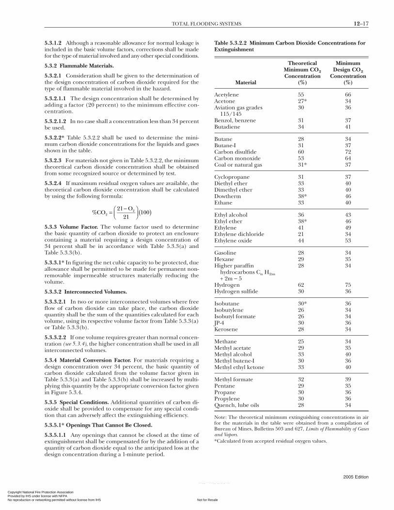
*Calculated from accepted residual oxygen values.
12–17TOTAL FLOODING SYSTEMS
Copyright National Fire PrProvided by IHS under liceNo reproduction or networ
5.3.1.2 Although a reasonable allowance for normal leakage isincluded in the basic volume factors, corrections shall be madefor the type of material involved and any other special conditions.
5.3.2 Flammable Materials.
5.3.2.1 Consideration shall be given to the determination ofthe design concentration of carbon dioxide required for thetype of flammable material involved in the hazard.
5.3.2.1.1 The design concentration shall be determined byadding a factor (20 percent) to the minimum effective con-centration.
5.3.2.1.2 In no case shall a concentration less than 34 percentbe used.
5.3.2.2* Table 5.3.2.2 shall be used to determine the mini-mum carbon dioxide concentrations for the liquids and gasesshown in the table.
5.3.2.3 For materials not given in Table 5.3.2.2, the minimumtheoretical carbon dioxide concentration shall be obtainedfrom some recognized source or determined by test.
5.3.2.4 If maximum residual oxygen values are available, thetheoretical carbon dioxide concentration shall be calculatedby using the following formula:
%CO21 O
22=
−⎛⎝⎜
⎞⎠⎟ ( )
21100
5.3.3 Volume Factor. The volume factor used to determinethe basic quantity of carbon dioxide to protect an enclosurecontaining a material requiring a design concentration of34 percent shall be in accordance with Table 5.3.3(a) andTable 5.3.3(b).
5.3.3.1* In figuring the net cubic capacity to be protected, dueallowance shall be permitted to be made for permanent non-removable impermeable structures materially reducing thevolume.
5.3.3.2 Interconnected Volumes.
5.3.3.2.1 In two or more interconnected volumes where freeflow of carbon dioxide can take place, the carbon dioxidequantity shall be the sum of the quantities calculated for eachvolume, using its respective volume factor from Table 5.3.3(a)or Table 5.3.3(b).
5.3.3.2.2 If one volume requires greater than normal concen-tration (see 5.3.4), the higher concentration shall be used in allinterconnected volumes.
5.3.4 Material Conversion Factor. For materials requiring adesign concentration over 34 percent, the basic quantity ofcarbon dioxide calculated from the volume factor given inTable 5.3.3(a) and Table 5.3.3(b) shall be increased by multi-plying this quantity by the appropriate conversion factor givenin Figure 5.3.4.
5.3.5 Special Conditions. Additional quantities of carbon di-oxide shall be provided to compensate for any special condi-tion that can adversely affect the extinguishing efficiency.
5.3.5.1* Openings That Cannot Be Closed.
5.3.5.1.1 Any openings that cannot be closed at the time ofextinguishment shall be compensated for by the addition of aquantity of carbon dioxide equal to the anticipated loss at the
design concentration during a 1-minute period.otection Association nse with NFPA
Not for Resaking permitted without license from IHS
--`,,,```-`-`,
Table 5.3.2.2 Minimum Carbon Dioxide Concentrations forExtinguishment
Material
TheoreticalMinimum CO2Concentration
(%)
MinimumDesign CO2
Concentration(%)
Acetylene 55 66Acetone 27* 34Aviation gas grades
115/14530 36
Benzol, benzene 31 37Butadiene 34 41
Butane 28 34Butane-I 31 37Carbon disulfide 60 72Carbon monoxide 53 64Coal or natural gas 31* 37
Cyclopropane 31 37Diethyl ether 33 40Dimethyl ether 33 40Dowtherm 38* 46Ethane 33 40
Ethyl alcohol 36 43Ethyl ether 38* 46Ethylene 41 49Ethylene dichloride 21 34Ethylene oxide 44 53
Gasoline 28 34Hexane 29 35Higher paraffin
hydrocarbons Cn H2m+ 2m − 5
28 34
Hydrogen 62 75Hydrogen sulfide 30 36
Isobutane 30* 36Isobutylene 26 34Isobutyl formate 26 34JP-4 30 36Kerosene 28 34
Methane 25 34Methyl acetate 29 35Methyl alcohol 33 40Methyl butene-I 30 36Methyl ethyl ketone 33 40
Methyl formate 32 39Pentane 29 35Propane 30 36Propylene 30 36Quench, lube oils 28 34
Note: The theoretical minimum extinguishing concentrations in airfor the materials in the table were obtained from a compilation ofBureau of Mines, Bulletins 503 and 627, Limits of Flammability of Gasesand Vapors.
2005 Edition
le
,`,,`,`,,`---

12–18 CARBON DIOXIDE EXTINGUISHING SYSTEMS
Copyright National FiProvided by IHS undeNo reproduction or ne
--`,,,```-`-`,,`,,`,`,,`---
5.3.5.1.2 This amount of carbon dioxide shall be appliedthrough the regular distribution system. (See 5.2.1.1 and A.5.5.2.)
5.3.5.2 Ventilating Systems.
5.3.5.2.1 For ventilating systems that cannot be shut down,additional carbon dioxide shall be added to the space throughthe regular distribution system in an amount computed bydividing the volume moved during the liquid discharge periodby the flooding factor.
5.3.5.2.2 This amount shall be multiplied by the materialconversion factor (determined from Figure 5.3.4) when the
Table 5.3.3(a) Flooding Factors
(A) (B) (C)
Volume ofSpace (ft3)
Volume FactorCalculated
Quantity (lb)(Not Less
Than)ft3/lb CO2 lb CO2/ft3
Up to 140 14 0.072 —141–500 15 0.067 10
501–1600 16 0.063 351601–4500 18 0.056 100
4501–50,000 20 0.050 250Over 50,000 22 0.046 2500
Table 5.3.3(b) Flooding Factors (SI Units)
(A) (B) (C)
Volume ofSpace (m3)
Volume FactorCalculated
Quantity (kg)(Not Less
Than)m3/kg CO2 kg CO2/m3
Up to 3.96 0.86 1.15 —3.97–14.15 0.93 1.07 4.514.16–45.28 0.99 1.01 15.1
45.29–127.35 1.11 0.90 45.4127.36–1415.0 1.25 0.80 113.5Over 1415.0 1.38 0.77 1135.0
Con
vers
ion
fact
or
Minimum design CO2 concentration (%)30 34 40 50 60 70 80 90
1
2
3
4
FIGURE 5.3.4 Material Conversion Factors.
design concentration is greater than 34 percent.
2005 Edition
re Protection Association r license with NFPA
Not fortworking permitted without license from IHS
5.3.5.3* For applications where the normal temperature ofthe enclosure is above 200°F (93°C), a 1 percent increase inthe calculated total quantity of carbon dioxide shall be pro-vided for each additional 5°F (2.8°C) above 200°F (93°C).
5.3.5.4 For applications where the normal temperature ofthe enclosure is below 0°F (−18°C), a 1 percent increase in thecalculated total quantity of carbon dioxide shall be providedfor each degree Fahrenheit below 0°F (−18°C).
5.3.5.5* Except for unusual conditions, it shall not be re-quired to provide extra carbon dioxide to maintain the designconcentration.
5.3.5.6 If a hazard contains a liquid having an auto-ignitiontemperature below its boiling point, the carbon dioxideconcentration shall be maintained for a period to allow theliquid temperature to cool below its auto-ignition tempera-ture. (See 6.3.3.4.)
5.3.5.7* Flooding Factor.
5.3.5.7.1 A flooding factor of 8 ft3/lb (0.22 m3/kg) shall beused in ducts and covered trenches.
5.3.5.7.2 If the combustibles represent a deep-seated fire, itshall be treated as described in Section 5.4.
5.4 Carbon Dioxide Requirements for Deep-Seated Fires.
5.4.1* General.
5.4.1.1 After the design concentration is reached, the con-centration shall be maintained for a substantial period oftime, but not less than 20 minutes.
5.4.1.2 Any possible leakage shall be given special consider-ation because no allowance is included in the basic floodingfactors.
5.4.2* Combustible Materials.
5.4.2.1* The design concentrations listed in Table 5.4.2.1 shallbe achieved for the hazards listed.
5.4.2.2 Other Deep-Seated Fires.
5.4.2.2.1 Flooding factors for other deep-seated fires shall bejustified to the satisfaction of the authority having jurisdictionbefore use.
5.4.2.2.2 Consideration shall be given to the mass of materialto be protected because the thermal insulating effects reducethe rate of cooling.
5.4.3 Volume Consideration.
5.4.3.1 The volume of the space shall be determined in accor-dance with 5.3.3.1.
5.4.3.2 The basic quantity of carbon dioxide required to pro-tect an enclosure shall be obtained by treating the volume ofthe enclosure by the flooding factor given in 5.4.2.
5.4.4 Special Conditions. Additional quantities of carbon di-oxide shall be provided to compensate for any special condi-tion that can adversely affect the extinguishing efficiency. (See5.3.5.2, 5.3.5.3, and 5.3.5.4.)
5.4.4.1 Any openings that cannot be closed at the time ofextinguishment shall be compensated for by the addition ofcarbon dioxide equal in volume to the expected leakage vol-
ume during the extinguishing period.Resale

12–19TOTAL FLOODING SYSTEMS
Copyright National Fire PrProvided by IHS under liceNo reproduction or networ
--`,,,```-`-`,,`,,`,`,,`---
5.4.4.2 If leakage is appreciable, consideration shall be givento an extended discharge system as covered in 5.5.3. (See also5.2.1.3.)
5.5 Distribution System.
5.5.1 General. The distribution system for applying carbondioxide to enclosed hazards shall be designed with due consid-eration for the materials involved and the nature of the enclo-sure, because these items can require various discharge timesand rates of application.
5.5.2* Rate of Application. The minimum design rate of appli-cation shall be based on the quantity of carbon dioxide andthe maximum time to achieve design concentration.
5.5.2.1* For surface fires, the design concentration shall beachieved within 1 minute from start of discharge.
5.5.2.2 For high-pressure systems, if a part of the hazard is tobe protected by total flooding, the discharge rate for the totalflooding portion shall be computed as specified in 6.3.2.3.
5.5.2.3 For deep-seated fires, the design concentration shallbe achieved within 7 minutes, but the rate shall be not lessthan that required to develop a concentration of 30 percent in2 minutes.
5.5.3* Enclosed Rotating Electrical Equipment. For enclosedrotating electrical equipment, a minimum concentration of30 percent shall be maintained for the deceleration period,but not less than 20 minutes.
5.5.4 Piping Systems.
5.5.4.1 Piping shall be designed in accordance with 4.7.5 todeliver the required rate of application at each nozzle.
5.5.4.2* High-pressure storage temperatures shall be permit-ted to range from 0°F (−18°C) to 130°F (54°C) without requir-ing special methods of compensating for changing flow rates.(See 4.6.5.5.)
5.5.5 Nozzle Sizing and Distribution. Nozzles used in connec-tion with total flooding systems with either high- or low-pressure supply shall be of a type suitable for the intendedpurpose and shall be located to achieve the best results.
5.5.5.1 Nozzle Selection.
5.5.5.1.1 The types of nozzles selected and their placementshall be such that the discharge will not unduly splash flam-mable liquids or create dust clouds that could extend the fire,create an explosion, or otherwise adversely affect the contents
Table 5.4.2.1 Flooding Factors for Specific Hazards
DesignConcentration
(%)
Volume Factors
ft3/lb CO2 m3/kg CO2 lb CO2/ft3
50 10 0.62 0.100
50 12 0.75 0.083(200 lb minimum
65 8 0.50 0.125
75 6 0.38 0.166
of the enclosure.
otection Association nse with NFPA
Not for Resaking permitted without license from IHS
5.5.5.1.2 Nozzles vary in design and discharge characteristicsand shall be selected on the basis of their adequacy for the useintended.
5.5.5.2 Spacing and sizing of nozzles in ductwork is depen-dent on many factors such as velocity in duct, location andeffectiveness of dampers, possible loading of duct walls withcombustible deposits, duct length, and cross-sectional di-mensions.
5.5.5.2.1 The nozzle locations and sizing shall be selected toensure distribution of the carbon dioxide throughout the en-tire length of the ductwork.
5.5.5.2.2 Automatic dampers shall be provided to close onsystem operation.
5.5.5.2.3 No allowance shall be required for inlet and outletduct openings that have surface hazards only. (See 5.3.5.7 andTable 5.4.2.1.)
5.6 Venting Consideration.
5.6.1* General. The venting of flammable vapors and pressurebuildup from the discharge of quantities of carbon dioxideinto closed spaces shall be considered. (See 5.2.1.5.)
5.6.2* Pressure Relief Venting. For very tight enclosures, thenecessary area of free venting shall be calculated from thefollowing equation:
XQ
P=
1 3.
where:X = free venting area (in.2)Q = calculated carbon dioxide flow rate (lb/min)P = allowable strength of enclosure (lb/ft2)
5.6.2.1 Satisfactory results shall be achieved by assuming theexpansion of carbon dioxide to be 9 ft3/lb (0.56 m3/kg).
5.6.2.2 For SI units, the following equation shall apply:
XQ
P=
239
where:X = free venting area (mm2)Q = calculated carbon dioxide flow rate (kg/min)P = allowable strength of enclosure (kPa)
Specific Hazardskg CO2/m3
1.60 Dry electrical hazards in general [spacesless than 2000 ft3 (56.6 m3)]
1.33(91 kg minimum)
Dry electrical hazards in general [spacesgreater than 2000 ft3 (56.6 m3)]
2.00 Record (bulk paper) storage, ducts,covered trenches
2.66 Fur storage vaults, dust collectors
)
2005 Edition
le

12–20 CARBON DIOXIDE EXTINGUISHING SYSTEMS
Copyright National FiProvided by IHS undeNo reproduction or ne
Chapter 6 Local Application Systems
6.1 General Information. See also Annex F.
6.1.1 Description. A local application system shall consist of afixed supply of carbon dioxide permanently connected to asystem of fixed piping with nozzles arranged to discharge di-rectly into the fire.
6.1.2* Uses. Local application systems shall be used for theextinguishment of surface fires in flammable liquids, gases,and shallow solids where the hazard is not enclosed or wherethe enclosure does not conform to the requirements for totalflooding.
6.1.3 General Requirements. Local application systems shallbe designed, installed, tested, and maintained in accordancewith the applicable requirements in previous chapters andwith the additional requirements set forth in this chapter.
6.1.4* Safety Requirements.
6.2 Hazard Specifications.
6.2.1 Extent of Hazard. The hazard shall be so isolated fromother hazards or combustibles that fire will not spread outsidethe protected area.
6.2.1.1 The entire hazard shall be protected.
6.2.1.2 The hazard shall include all areas that are, or can be-come, coated by combustible liquids or shallow solid coatings,such as areas subject to spillage, leakage, dripping, splashing, orcondensation.
6.2.1.3 The hazard shall also include all associated materialsor equipment, such as freshly coated stock, drain boards,hoods, ducts, and so forth, that could extend fire outside orlead fire into the protected area.
6.2.1.4 A series of interexposed hazards shall be permitted tobe subdivided into smaller groups or sections with the ap-proval of the authority having jurisdiction.
6.2.1.5 Systems for such hazards shall be designed to giveimmediate independent protection to adjacent groups or sec-tions as needed.
6.2.2 Location of Hazard.
6.2.2.1 The hazard shall be permitted to be indoors, partlysheltered, or completely out of doors.
6.2.2.2 It is essential that the carbon dioxide discharge shallbe such that winds or strong air currents do not impair theprotection.
6.3 Carbon Dioxide Requirements.
6.3.1* General. The quantity of carbon dioxide required forlocal application systems shall be based on the total rate ofdischarge needed to blanket the area or volume protected andthe time that the discharge must be maintained to ensurecomplete extinguishment.
6.3.1.1* High-Pressure Storage.
6.3.1.1.1 For systems with high-pressure storage, the com-puted quantity of carbon dioxide shall be increased by 40 per-cent to determine nominal cylinder storage capacity because
--`,,,```-`-`,,`,,`,`,,`---
only the liquid portion of the discharge is effective.
2005 Edition
re Protection Association r license with NFPA
Not fortworking permitted without license from IHS
6.3.1.1.2 This increase in cylinder storage capacity shall notbe required for the total flooding portion of combined localapplication–total flooding systems.
6.3.1.2* The quantity of carbon dioxide in storage shall beincreased by an amount to compensate for liquid vaporized incooling the piping.
6.3.2 Rate of Discharge. Nozzle discharge rates shall be deter-mined by either the surface method, as covered in Section 6.4,or the volume method, as covered in Section 6.5.
6.3.2.1 The total rate of discharge for the system shall be thesum of the individual rates of all the nozzles or discharge de-vices used on the system.
6.3.2.2 For low-pressure systems, if a part of the hazard is tobe protected by total flooding, the discharge rate for the totalflooding part shall develop the required concentration in notmore than the discharge time used for the local applicationpart of the system.
6.3.2.3 For high-pressure systems, if a part of the hazard is tobe protected by total flooding, the discharge rate for the totalflooding part shall be computed by dividing the quantity re-quired for total flooding by the factor 1.4 and by the time ofthe local application discharge in minutes, as shown in thefollowing equation:
QW
TFF
L
=1 4.
where:QF = rate of flow for the total flooding portion
[lb/min (kg/min)]WF = total quantity of carbon dioxide for the total
flooding portion [lb (kg)]TL = liquid discharge time for the local application
portion (min)
6.3.3* Duration of Discharge.
6.3.3.1 The minimum effective discharge time for computingquantity shall be 30 seconds.
6.3.3.2 The minimum time shall be increased to compensatefor any hazard condition that would require a longer coolingperiod to ensure complete extinguishment.
6.3.3.3 Where there is a possibility that metal or other mate-rial can become heated above the ignition temperature of thefuel, the effective discharge time shall be increased to allowadequate cooling time.
6.3.3.4* Where the fuel has an auto-ignition point below itsboiling point, such as paraffin wax and cooking oils, the effec-tive discharge time shall be increased to permit cooling of thefuel to prevent re-ignition.
6.3.3.5 The minimum liquid discharge time shall be 3 minutes.
6.4 Rate-by-Area Method.
6.4.1 General. The area method of system design shall beused where the fire hazard consists primarily of flat surfaces orlow-level objects associated with horizontal surfaces.
6.4.1.1 System design shall be based on listing or approvaldata for individual nozzles.
6.4.1.2 Extrapolation of such data above or below the upper
or lower limits shall not be permitted.Resale

12–21LOCAL APPLICATION SYSTEMS
Copyright National Fire PrProvided by IHS under liceNo reproduction or networ
6.4.2 Nozzle Discharge Rates. The design discharge ratethrough individual nozzles shall be determined on the basis oflocation or projection distance in accordance with specific ap-provals or listings.
6.4.2.1* The discharge rate for overhead-type nozzles shall bedetermined solely on the basis of distance from the surfaceeach nozzle protects.
6.4.2.2* The discharge rate for tankside nozzles shall be deter-mined solely on the basis of the throw or projection requiredto cover the surface each nozzle protects.
6.4.3 Area per Nozzle. The maximum area protected by eachnozzle shall be determined on the basis of location or projec-tion distance and the design discharge rate in accordance withspecific approvals or listings.
6.4.3.1 The same factors used to determine the design dis-charge rate shall be used to determine the maximum area tobe protected by each nozzle.
6.4.3.2 The portion of the hazard protected by individualoverhead-type nozzles shall be considered as a square area.
6.4.3.3 The portion of the hazard protected by individualtankside or linear nozzles is either a rectangular or square areain accordance with spacing and discharge limitations stated inspecific approvals or listings.
6.4.3.4* Where coated rollers or other similar irregular shapesare to be protected, the projected wetted area shall be used todetermine nozzle coverage.
6.4.3.5 Where coated surfaces are to be protected, the areaper nozzle shall be permitted to be increased to a maximum of40 percent over the areas given in specific approvals or listings.
6.4.3.5.1 Coated surfaces shall be defined as those designedfor drainage that are constructed and maintained so that nopools of liquid will accumulate over a total area exceeding 10percent of the protected surface.
6.4.3.5.2 Subsection 6.4.3.5 shall not apply where there is aheavy buildup of residue. (See 6.1.2.)
6.4.3.6 Where local application nozzles are used for protec-tion across openings as defined in 5.2.1.4 and 5.2.1.5, the areaper nozzle given by specific approval or listing shall be permit-ted to be increased to a maximum of 20 percent.
6.4.3.7 Where deep-layer flammable liquid fires are to beprotected, a minimum freeboard of 6 in. (152 mm) shall beprovided unless otherwise noted in approvals or listings ofnozzles.
6.4.4 Location and Number of Nozzles. A quantity of nozzlesshall be used to cover the entire hazard area on the basis of theunit areas protected by each nozzle.
6.4.4.1 Tankside or linear nozzles shall be located in accor-dance with spacing and discharge rate limitations stated inspecific approvals or listings.
6.4.4.2 Overhead-type nozzles shall be installed perpendicu-lar to the hazard and centered over the area protected by thenozzle.
6.4.4.2.1 Overhead-type nozzles shall also be permitted to beinstalled at angles between 45 degrees and 90 degrees from
the plane of the hazard surface as prescribed in 6.4.4.3.otection Association nse with NFPA
Not for Resaking permitted without license from IHS
--`,,,```-`-`,,`,,`,`,,`---
6.4.4.2.2 The height used in determining the necessary flowrate and area coverage shall be the distance from the aimingpoint on the protected surface to the face of the nozzle mea-sured along the axis of the nozzle.
6.4.4.3 Nozzles Installed at an Angle.
6.4.4.3.1 When nozzles are installed at an angle, they shall beaimed at a point measured from the near side of the areaprotected by the nozzle.
6.4.4.3.2 This location shall be calculated by multiplying thefractional aiming factor in Table 6.4.4.3.2 by the width of thearea protected by the nozzle.
6.4.4.4 Nozzles shall be located so as to be free of possibleobstructions that could interfere with the projection of thedischarged carbon dioxide.
6.4.4.5* Nozzles shall be located so as to develop an extin-guishing atmosphere over coated stock extending above a pro-tected surface.
6.4.4.6 The possible effects of air currents, winds, and forceddrafts shall be compensated for by nozzle locations or by pro-viding additional nozzles to protect the outside areas of thehazard.
6.5 Rate-by-Volume Method.
6.5.1 General. The volume method of system design shall beused where the fire hazard consists of three-dimensional ir-regular objects that cannot be easily reduced to equivalentsurface areas.
6.5.2 Assumed Enclosure. The total discharge rate of the sys-tem shall be based on the volume of an assumed enclosureentirely surrounding the hazard.
6.5.2.1 The assumed enclosure shall be based on an actualclosed floor unless special provisions are made to take care ofbottom conditions.
6.5.2.2 The assumed walls and ceiling of this enclosure shallbe at least 2 ft (0.6 m) from the main hazard unless actual wallsare involved, and they shall enclose all areas of possible leak-age, splashing, or spillage.
6.5.2.3 No deductions shall be made for solid objects withinthis volume.
6.5.2.4 A minimum dimension of 4 ft (1.2 m) shall be used incalculating the volume of the assumed enclosure.
6.5.2.5 If the hazard can be subjected to winds or forceddrafts, the assumed volume shall be increased to compensate
Table 6.4.4.3.2 Aiming Factors for Angular Placement ofNozzles, Based on 6 in. (152 mm) Freeboard
Discharge Angle* Aiming Factors†
45–60 1⁄460–75 1⁄4–3⁄875–90 3⁄8–1⁄2
90 (perpendicular) 1⁄2 (center)
*Degrees from plane of hazard surface.†Fractional amount of nozzle coverage area.
for losses on the windward sides.
2005 Edition
le

12–22 CARBON DIOXIDE EXTINGUISHING SYSTEMS
Copyright National FiProvided by IHS undeNo reproduction or ne
6.5.3 System Discharge Rate.
6.5.3.1 The total discharge rate for the basic system shall beequal to 1 lb/min·ft3 (16 kg/min·m3) of assumed volume.
6.5.3.2* If the assumed enclosure has a closed floor and ispartly defined by permanent continuous walls extending atleast 2 ft (0.6 m) above the hazard (where the walls are notnormally a part of the hazard), the discharge rate shall bepermitted to be proportionately reduced to not less than0.25 lb/min·ft3 (4 kg/min·m3) for actual walls completelysurrounding the enclosure.
6.5.4 Location and Number of Nozzles. A quantity of nozzlesshall be used to cover the entire hazard volume on the basisof the system discharge rate as determined by the assumedvolume.
6.5.4.1 Nozzles shall be located and directed so as to retainthe discharged carbon dioxide in the hazard volume by coop-eration between nozzles and objects in the hazard volume.
6.5.4.2 Nozzles shall be located so as to compensate for anypossible effects of air currents, winds, or forced drafts.
6.5.4.3 The design discharge rates through individualnozzles shall be determined on the basis of location or projec-tion distance in accordance with specific approvals or listingsfor surface fires.
6.6 Distribution System.
6.6.1 General. The system shall be designed to provide aneffective discharge of carbon dioxide promptly before exces-sive amounts of heat can be absorbed by materials within thehazard.
6.6.1.1 The carbon dioxide supply shall be located as near tothe hazard as practicable and yet not exposed to the fire, andthe pipeline shall be as direct as practicable with a minimumnumber of turns in order to get carbon dioxide to the firepromptly.
6.6.1.2 The system shall be designed for automatic operationexcept where the authorities having jurisdiction permitmanual operation.
6.6.2* Piping Systems. Piping shall be designed in accordancewith 4.7.5 to deliver the required rate of application at eachnozzle.
6.6.3 Discharge Nozzles. The nozzles used shall be listed orapproved for rate of discharge, effective range, and pattern orarea coverage.
6.6.3.1 The equivalent orifice size used in each nozzle shallbe determined in accordance with 4.7.5 to match the designdischarge rate.
6.6.3.2 Nozzles shall be accurately located and directed inaccordance with the system design requirements as covered inSections 6.4 and 6.5.
Chapter 7 Hand Hose Line Systems
7.1 General Information.
7.1.1* Description. Hand hose line systems shall consist of ahose reel or rack, hose, and discharge nozzle assembly con-
nected by fixed piping to a supply of carbon dioxide.2005 Edition
re Protection Association r license with NFPA
Not fortworking permitted without license from IHS
--`,,,```
7.1.2 Uses. Hand hose line systems shall be permitted to beused to supplement fixed fire protection systems or to supple-ment first aid fire extinguishers for the protection of specifichazards for which carbon dioxide is the extinguishing agent.
7.1.2.1 These systems shall not be used as a substitute forother fixed carbon dioxide fire-extinguishing systemsequipped with fixed nozzles, except where the hazard cannotadequately or economically be provided with fixed protection.
7.1.2.2 The decision as to whether hose lines are applicableto the particular hazard shall rest with the authority havingjurisdiction.
7.1.3 General Requirements. Hand hose line systems shall beinstalled and maintained in accordance with the applicablerequirements of Chapters 4, 5, and 6, except as outlined inSections 7.2 through 7.6.
7.1.4* Safety Requirements.
7.2 Hazard Specifications. Hand hose line systems shall bepermitted to be used to combat fires in all hazards coveredunder Chapter 1, except those that are inaccessible and be-yond the scope of manual fire fighting.
7.3 Location and Spacing.
7.3.1 Location.
7.3.1.1 Hand hose line stations shall be placed such that theyare easily accessible and within reach of the most distant haz-ard that they are expected to protect.
7.3.1.2 In general, they shall not be located such that they areexposed to the hazard, nor shall they be located inside anyhazard area protected by a total flooding system.
7.3.2 Spacing. If multiple-hose stations are used, they shall bespaced so that any area within the hazard can be covered byone or more hose lines.
7.4 Carbon Dioxide Requirements.
7.4.1 Rate and Duration of Discharge.
7.4.1.1 The rate and duration of discharge and consequentlythe amount of carbon dioxide shall be determined by the typeand potential size of the hazard.
7.4.1.2 A hand hose line shall have a quantity of carbon diox-ide to permit its use for at least 1 minute.
7.4.2 Provision for Use by Inexperienced Personnel. The pos-sibility of these hose lines being used by inexperienced per-sonnel shall be considered, and a provision shall be made sothat there will be a supply of carbon dioxide to enable person-nel to effect extinguishment of the hazards that they are likelyto encounter.
7.4.3 Simultaneous Use.
7.4.3.1 Where simultaneous use of two or more hose lines ispossible, a quantity of carbon dioxide shall be available to sup-port the maximum number of nozzles that are likely to beused at any one time for at least 1 minute.
7.4.3.2 All supply piping shall be sized for the simultaneousoperation of the number of nozzles that are likely to be used.
7.5 Equipment Specifications.
7.5.1 Hose. Hose lines on systems with high-pressure supply
shall have a minimum bursting pressure of 5000 psi (34,474 kPa),Resale
-`-`,,`,,`,`,,`---

12–23MARINE SYSTEMS
Copyright National Fire PrProvided by IHS under liceNo reproduction or networ
--`,,,```-`-`,,`,,`,`,,`---
and hose lines of systems with low-pressure supply shall have aminimum bursting pressure of 1800 psi (12,411 kPa). (See 4.8.2.)
7.5.2* Discharge Nozzle Assembly. Hose lines shall beequipped with a discharge nozzle assembly that can be easilyhandled by one operator and that contains a quick-openingshutoff valve to control the flow of carbon dioxide through thenozzle and a handle for directing the discharge.
7.5.3 Hose Line Storage.
7.5.3.1 The hose shall be coiled on a hose reel or rack suchthat it will be ready for immediate use without the necessity ofcoupling and such that it can be uncoiled with a minimum ofdelay.
7.5.3.2 If installed outdoors, it shall be protected against theweather.
7.5.4* Charging the Hose Line.
7.5.4.1 All controls for actuating the system shall be locatedin the immediate vicinity of the hose reel.
7.5.4.2* The carbon dioxide supply shall be located as closeto the hose reel as possible so that liquid carbon dioxidewill be supplied to the hose line with a minimum of delayafter actuation.
7.5.4.3 Except when in actual use, pressure shall not be per-mitted to remain in the hose line.
7.6 Training.
7.6.1 Successful extinguishment of fire with hand hose linesgreatly depends on the individual ability and technique of theoperator.
7.6.2 All personnel who are likely to use this equipment atthe time of a fire shall be trained in its operation and in thefire-fighting techniques applicable to this equipment.
Chapter 8 Standpipe Systems and Mobile Supply
8.1 General Information.
8.1.1* Description. A standpipe system shall be a fixed totalflooding, local application, or hand hose line system without apermanently connected carbon dioxide supply.
8.1.2* Uses. Standpipe systems shall be installed only with theapproval of the authority having jurisdiction.
8.1.3 General Requirements. Standpipe systems and mobilesupply shall be installed and maintained in accordance withthe requirements in Chapters 4, 5, 6, and 7, in addition tothose outlined in Sections 8.2 through 8.5.
8.1.3.1 Piping shall be installed in accordance with the re-quirements applicable for the system if a permanently con-nected supply is used.
8.1.3.2 Appreciable lengths of piping on the portable supplyshall be taken into account.
8.2 Hazard Specifications. Standpipe systems and mobile sup-ply shall be permitted to be used to protect hazards describedin Chapters 4, 5, 6, and 7, where extinguishment will not beadversely affected by the delay in obtaining effective dischargeof carbon dioxide while the mobile supply is being brought to
the scene and coupled to the standpipe system.otection Association nse with NFPA
Not for Resaking permitted without license from IHS
8.3 Standpipe Requirements.
8.3.1 The supply piping of standpipe systems shall beequipped with quick-change couplings and shall terminate inan easily accessible and well-marked location for connectionto the mobile supply.
8.3.2 This location shall be marked with the amount of car-bon dioxide required and the required duration of discharge.
8.4 Mobile Supply Requirements.
8.4.1* Capacity. The mobile supply shall have a capacity inaccordance with the provisions of Chapters 4, 5, 6, and 7.
8.4.2 Coupling.
8.4.2.1 The mobile supply shall be provided with a means fortransferring carbon dioxide into the standpipe system.
8.4.2.2 Quick-change couplings shall be provided to permitthese connections to be made as rapidly as possible.
8.4.3 Mobility.
8.4.3.1 The storage container or containers of carbon dioxideshall be mounted on a movable vehicle that can be brought tothe scene of the fire by manual means, by a separate motor ve-hicle, or under its own power.
8.4.3.2 The means of transporting the mobile supply shall bedependable and capable of getting to the fire with a minimumof delay.
8.4.4 Location. The mobile supply shall be kept close to thehazards that it is intended to protect so that fire extinguish-ment can be started as soon as possible after the fire breaksout.
8.4.5 Accessories. Mobile supply for standpipe systems shallbe permitted to be provided with hand hose lines as accessoryequipment for the protection of small scattered hazards or as asupplement to standpipe systems or other fixed protection.
8.5* Training. It is imperative that those persons assigned tothe units shall be trained in the use and maintenance of thestandpipe systems and mobile supply.
Chapter 9 Marine Systems
9.1 Special Definitions. The following definitions shall applyto Chapter 9:
(1) Marine systems (See 3.4.1.)(2) Space
(a) Cargo space (See 3.4.2.1.)(b) Electrical equipment space (See 3.4.2.2.)(c)*Machinery space (See 3.4.2.3.)(d)*Vehicle space (See 3.4.2.4.)
9.2 General.
9.2.1* Outline. This chapter outlines the modifications neces-sary for marine systems.
9.2.2 All other requirements of this standard shall apply tomarine systems except as modified by this chapter.
9.3 System Requirements.
9.3.1 Components. System components shall be specificallylisted or approved for carbon dioxide system marine appli-
cations.2005 Edition
le

12–24 CARBON DIOXIDE EXTINGUISHING SYSTEMS
Copyright National FiProvided by IHS undeNo reproduction or ne
9.3.2 Operating Instructions.
9.3.2.1 Instructions for the operation of the system shall belocated in a conspicuous place at or near all manual controlsand in the carbon dioxide storage room.
9.3.2.2 For systems in which the carbon dioxide storage is notwithin the protected space, the operating instructions shallinclude a chart indicating the location of the emergency con-trol to be used if the normal controls fail to operate.
9.3.3 System Actuation.
9.3.3.1 Two separate valves shall be provided for releasingcarbon dioxide into any protected space.
9.3.3.1.1 One valve shall control discharge from the carbondioxide storage.
9.3.3.1.2 The second valve shall control carbon dioxide dis-charge into the protected space(s). (See 4.5.4.6.)
9.3.3.1.3 For systems that contain 300 lb (136 kg) of carbondioxide storage or less, only one valve shall be required to beused for the release of the system provided that the protectedspace is normally unoccupied and has horizontal egress.
9.3.3.2* Controls.
9.3.3.2.1 A separate manually operated control shall be pro-vided to operate each valve required by 9.3.3.1.
9.3.3.2.2 A set of controls shall be located outside at least oneof the main means of egress from each protected space.
9.3.3.3* In addition to the manually operated controls re-quired by 9.3.3.2, each of the valves required by 9.3.3.1 shall beprovided with its own emergency manual control.
9.3.3.4 Release Box.
9.3.3.4.1 Controls for the valves required by 9.3.3.2 shall belocated inside a release box clearly identified for the protectedspace.
9.3.3.4.2 If the box containing the controls is to be locked, akey to the box shall be provided in a break-glass-type enclosureconspicuously located adjacent to the box.
9.3.3.5* Source of Power.
9.3.3.5.1 In addition to the requirements of 4.3.3.4, audiblepredischarge alarms shall be provided that depend on nosource of power other than carbon dioxide pressure.
9.3.3.5.2 The time delay required by 4.3.3.2 shall be a mini-mum of 20 seconds and shall depend on no source of powerother than carbon dioxide pressure.
9.3.4 Carbon Dioxide Storage.
9.3.4.1 Carbon dioxide storage shall be permitted inside nor-mally unoccupied protected spaces for systems that containnot more than 300 lb (136 kg) of carbon dioxide storage andare equipped for automatic actuation.
9.3.4.2 Low-pressure systems shall be provided with dual re-frigeration units and shall be constructed in accordance with46 CFR 58.20.
9.3.4.3 When the carbon dioxide containers are located out-side a protected space, they shall be stored in a room that shallbe situated in a safe and readily accessible location and shallbe effectively ventilated so that the agent containers are not
--`,,,```-`-`,,`,,`,`,,`---
exposed to ambient temperatures outlined in 4.6.5.5.
2005 Edition
re Protection Association r license with NFPA
Not fortworking permitted without license from IHS
9.3.4.3.1 Common bulkheads and decks located between agentcontainer storage rooms and protected spaces shall be protectedwith A-60 class structural insulation as defined by 46 CFR 72.
9.3.4.3.2 Doors and other means of closing any openingtherein that form the boundaries between such rooms andadjoining protected spaces shall be gastight.
9.3.4.3.3 Agent container storage rooms shall be accessiblewithout having to pass through the space being protected.
9.3.4.3.4 Access doors shall open outward.
9.3.4.3.5 For systems that contain 300 lb (136 kg) of carbondioxide storage or less, only one valve shall be required to beused for the release of the system provided that the protectedspace is normally unoccupied and has horizontal egress.
9.3.5 System Piping.
9.3.5.1* Where necessary, drains shall be provided for the re-moval of accumulated moisture.
9.3.5.2 Carbon dioxide piping shall not be fitted with drainsor other openings within living quarters.
9.3.5.3 Carbon dioxide piping shall be used for no other pur-pose, except that carbon dioxide piping shall be permitted tobe used in an air-sampling-type smoke detection system.
9.3.6 System Design. System design shall comply with Chap-ters 5, 6, and 7 except as described in 9.3.6.1 through 9.3.6.4.2.
9.3.6.1 Machinery Spaces. Machinery spaces shall be designedto a 34-percent concentration based on the gross volume.
9.3.6.1.1 Eighty-five percent of the concentration requiredby 9.3.6.1 shall be achieved within 2 minutes from the start ofdischarge.
9.3.6.1.2 Gross volume shall include the casing.
9.3.6.2 Cargo Spaces. Cargo spaces other than vehicle spacesshall be supplied with carbon dioxide based on 1 lb/30 ft3 basedon the gross volume.
9.3.6.2.1 The initial quantity of carbon dioxide dischargedshall be based on the net volume of the space as determinedby the amount of cargo in the cargo space.
9.3.6.2.2 Additional carbon dioxide shall be released asneeded to maintain control of the fire.
9.3.6.2.3 Clear instructions shall be posted within the carbondioxide storage room detailing the carbon dioxide releaseprocedure.
9.3.6.3 Vehicle Spaces.
9.3.6.3.1 Vehicle spaces where the vehicles contain morethan 5 gal (19 L) of fuel (gasoline or diesel) shall be designedto a 34-percent concentration based on the gross volume.
9.3.6.3.2 Eighty-five percent of this concentration shall beachieved within 2 minutes from start of discharge.
9.3.6.4 Vehicle Spaces.
9.3.6.4.1 Vehicle spaces where the vehicles contain 5 gal(19 L) or less of fuel (gasoline or diesel) shall be designedto a 34-percent concentration based on the gross volume.
9.3.6.4.2 Two-thirds of this concentration shall be achieved
within 10 minutes from start of discharge.Resale

12–25ANNEX A
Copyright National Fire PrProvided by IHS under liceNo reproduction or networ
--`,,,```-`-`,,`,,`,`,,`---
9.3.7 Electrical Equipment Spaces. Electrical equipmentspaces shall be treated as a dry electrical hazard in accordancewith Chapter 5.
9.4 Inspection and Maintenance. Inspection and maintenanceshall comply with 4.8.3 and Section 9.4.
9.4.1 General. Prior to testing or maintenance of a fixed car-bon dioxide system, all personnel shall be evacuated from theprotected space. (See Section 4.3.)
9.4.2 Approval of Installations.
9.4.2.1 The approval test described in 9.4.2.1.1 through9.4.2.1.4 shall be conducted prior to the tests required by4.4.3.
9.4.2.1.1 Pressure tests of the piping shall be performed tomeet the requirements of 9.4.2.1.2 through 9.4.2.1.4.
9.4.2.1.2 The test medium shall be a dry, noncorrosive gassuch as nitrogen or carbon dioxide.
9.4.2.1.3 When pressurizing the piping, pressure shall be in-creased in 50 psi (3.5 bar) increments.
9.4.2.1.4 Once the pressure in the pipe has reached the re-quired test pressure, the pressure source shall be shut off anddisconnected from the pipe.
CAUTION: Pneumatic pressure testing creates a potentialrisk of injury to personnel in the area, as a result of airborneprojectiles, if rupture of the piping system occurs. Prior to thepneumatic pressure test, the area in which the pipe is locatedshall be evacuated and appropriate safeguards shall be pro-vided for test personnel.
9.4.2.2 High-Pressure Systems.
9.4.2.2.1 Systems with Stop Valves.
9.4.2.2.1.1 All piping from the carbon dioxide supply to thestop valves shall be subjected to a minimum pressure of 1000 psi(6895 kPa).
9.4.2.2.1.2 The leakage during a 2-minute period shall notexceed a pressure drop of 10 percent.
9.4.2.2.1.3 All piping between the stop valves and the nozzlesshall be subjected to a minimum pressure of 600 psi (4137 kPa).
9.4.2.2.1.4 The leakage during a 2-minute period shall notexceed a pressure drop of 10 percent.
9.4.2.2.2 Systems Without Stop Valves.
9.4.2.2.2.1 All piping from the carbon dioxide supply to thenozzles shall be subjected to a minimum pressure of 600 psi(4137 kPa).
9.4.2.2.2.2 The leakage during a 2-minute period shall notexceed a pressure drop of 10 percent.
9.4.2.3 Low-Pressure Systems.
9.4.2.3.1 Normally Pressurized Piping.
9.4.2.3.1.1 All piping that is normally pressurized shall besubjected to a pressure test of minimum 300 psi (2068 kPa).
9.4.2.3.1.2 No leakage shall be permitted from the piping
during a 2-minute test.otection Association nse with NFPA
Not for Resaking permitted without license from IHS
9.4.2.3.2 Piping Between the Tank Shutoff Valve and Nozzles.
9.4.2.3.2.1 All piping between the tank shutoff valve and thenozzles shall be subjected to a minimum pressure test of 300 psi(2068 kPa).
9.4.2.3.2.2 The leakage during a 2-minute period shall notexceed a pressure drop of 10 percent.
9.4.3 Predischarge Delays, Alarms, and Shutdowns.
9.4.3.1 Predischarge delays and alarms and ventilationshutdowns shall be tested by flowing carbon dioxide intothe system.
9.4.3.2 Predischarge delays that are not accurate to within+20 percent/−0 percent at 70°F (21°C) of their rating shall bereplaced.
9.4.4 Verification. Compliance with 9.3.2 shall be verified.
Annex A Explanatory Material
Annex A is not a part of the requirements of this NFPA documentbut is included for informational purposes only. This annex containsexplanatory material, numbered to correspond with the applicable textparagraphs.
A.1.1 Portable carbon dioxide equipment is covered inNFPA 10, Standard for Portable Fire Extinguishers. The use of car-bon dioxide for inerting is covered in NFPA 69, Standard onExplosion Prevention Systems.
A.1.3.5 Exposure to carbon dioxide discharge poses a hazardto personnel; therefore, additional safety features for all newinstallations and for retrofitting of existing systems are pro-vided in Section 4.3.
Safety to personnel is of paramount importance; therefore,these additional safety features should be installed as soon aspossible but no later than August 7, 2006.
The installation of the safety signs per 4.3.2 does not re-quire any modifications to the installation and should be ac-complished immediately.
The addition of supervised lock-out valves, per 4.3.3.6 and4.3.3.6.1, and pneumatic predischarge alarms and pneumatictime delays, per 4.5.5.7, require that the system flow calcula-tions be verified and be in accordance with this standard. Thatis, the addition of piping equipment (valve and time delay)adds equivalent pipe length to the system. The pneumatic pre-discharge alarm requires carbon dioxide flow to sound. Therevised design should be in accordance with the agent quan-tity requirements of this standard.
These modifications could necessitate revisions to, upgrad-ing of, or replacement of system components, including con-trol units.
As part of the process of implementing these modifications,the authority having jurisdiction should be consulted for addi-tional recommendations or requirements.
A.1.4 See Table A.1.4.If a value for measurement as given in this standard is fol-
lowed by an equivalent value in other units, the first valuestated is to be regarded as the requirement. A given equivalentvalue can be approximate.
The conversion procedure for the SI units is to multiply thequantity by the conversion factor and then round the result to
the appropriate number of significant digits.2005 Edition
le

12–26 CARBON DIOXIDE EXTINGUISHING SYSTEMS
Copyright National FiProvided by IHS undeNo reproduction or ne
--`,,,``
A.3.2.1 Approved. The National Fire Protection Associationdoes not approve, inspect, or certify any installations, proce-dures, equipment, or materials; nor does it approve or evalu-ate testing laboratories. In determining the acceptability ofinstallations, procedures, equipment, or materials, the author-ity having jurisdiction may base acceptance on compliancewith NFPA or other appropriate standards. In the absence ofsuch standards, said authority may require evidence of properinstallation, procedure, or use. The authority having jurisdic-tion may also refer to the listings or labeling practices of anorganization that is concerned with product evaluations and isthus in a position to determine compliance with appropriatestandards for the current production of listed items.
A.3.2.2 Authority Having Jurisdiction (AHJ). The phrase “au-thority having jurisdiction,” or its acronym AHJ, is used inNFPA documents in a broad manner, since jurisdictions andapproval agencies vary, as do their responsibilities. Where pub-lic safety is primary, the authority having jurisdiction may be afederal, state, local, or other regional department or indi-vidual such as a fire chief; fire marshal; chief of a fire preven-tion bureau, labor department, or health department; build-ing official; electrical inspector; or others having statutoryauthority. For insurance purposes, an insurance inspection de-partment, rating bureau, or other insurance company repre-sentative may be the authority having jurisdiction. In manycircumstances, the property owner or his or her designatedagent assumes the role of the authority having jurisdiction; atgovernment installations, the commanding officer or depart-mental official may be the authority having jurisdiction.
A.3.2.4 Listed. The means for identifying listed equipmentmay vary for each organization concerned with product evalu-ation; some organizations do not recognize equipment aslisted unless it is also labeled. The authority having jurisdic-tion should utilize the system employed by the listing organi-zation to identify a listed product.
A.3.3.6 Normally Unoccupied. A normally unoccupied enclo-sure is one that is occasionally visited by personnel. Examplesof areas considered normally unoccupied are transformerbays, switch-houses, pump rooms, vaults, engine test stands,cable vaults, cable spreading rooms, utility tunnels, microwaverelay stations, flammable liquid storage areas, enclosed energysystems, shipboard cargo holds, robotic paint spray areas, andcomputer room subfloors.
A.3.3.8.1 High Pressure. At 70°F (21°C), the pressure in thistype of storage is 850 psi (5860 kPa).
A.3.3.8.2 Low Pressure. At this temperature the pressure in
Table A.1.4 Units
Name of UnitUnit
Symbol Conversion Factor
pascal Pa 1 psi = 6894.757 Pakilogram kg 1 lb = 0.4536 kgmeter m 1 ft = 0.3048 mmillimeter mm 1 in. = 25.4 mm
Note: For additional conversions and information, see ASTM SI 10,Standard for Use of the International System of Units (SI): The Modern MetricSystem.
this type of storage is 300 psi (2068 kPa).
2005 Edition
re Protection Association r license with NFPA
Not fortworking permitted without license from IHS
`-`-`,,`,,`,`,,`---
A.3.3.10.3 Pre-Engineered System. Pre-engineered systemscan incorporate special nozzles, flow rates, methods of appli-cation, nozzle placement, and quantities of carbon dioxidethat could differ from those detailed elsewhere in this stan-dard because they are designed for very specific hazards. Allother requirements of the standard apply. It is possible for thenormal manual control to qualify as the emergency manualcontrol if the provisions of 4.5.1 are satisfied.
The hazards protected by these systems are specifically limitedas to type and size. Limitations on hazards that can be protectedby these systems are contained in the manufacturer’s installationmanual, which is referenced as part of the listing.
A.4.1.1 The choice of fire suppression agent should be deter-mined at the early stages of hazard evaluation. Coordinationamong specifiers, consultants, AHJs, designers, purchasers, andbuilding owners should determine agreement that carbon diox-ide is the most suitable for the application. Total flooding carbondioxide systems are not intended to be acceptable substitutes forHalon 1301 total flooding systems used for normally occupiedenclosures. Some examples of normally occupied enclosureswith surface fire hazards that should be considered for othertypes of clean fire-extinguishing agents are offices, computerrooms, control rooms, data centers, and libraries.
When verifying “equivalent levels of fire protection,” thedesigner should consider the hazard characteristics and fire-extinguishing agent limitations that may affect the system per-formance. Examples include the following:
(1) Fast-growth fires(2) High-energy output fires(3) Deep-seated fires(4) Fire suppression agent storage temperature limits(5) Ambient temperature of hazard(6) Design capabilities for unenclosable openings(7) Design capabilities for extended discharge systems(8) Contamination to product, surrounding area, or envi-
ronment(9) Requirements for continued operations in areas where
persistent ignition sources may be present (e.g., special-ized hazards associated with national defense, security,and special chemical or radioactive material handling)
(10) Undefined reaction of fire suppression agent to the hazard
A.4.2.1 The discharge of liquid carbon dioxide is known toproduce electrostatic charges that, under certain conditions,could create a spark. (See NFPA 77, Recommended Practice onStatic Electricity.)
Carbon dioxide does not extinguish fires where the follow-ing materials are actively involved in the combustion process:
(1) Chemicals containing their own oxygen supply, such ascellulose nitrate
(2) Reactive metals such as sodium, potassium, magnesium,titanium, and zirconium
(3) Metal hydridesWhile carbon dioxide does not extinguish these fires, it
does not react dangerously with these materials or increasetheir burning rate. Carbon dioxide, if used in this type of situ-ation in a total flooding system, provides protection for adja-cent combustibles or can be successfully used if the reactivemetals or hydrides are first covered by another material. Thefollowing are examples of this latter condition:
(1) Sodium stored or used under kerosene(2) Cellulose nitrate in solution of lacquer thinner(3) Magnesium chips covered with heavy oil
Resale

12–27ANNEX A
Copyright National Fire PrProvided by IHS under liceNo reproduction or networ
For local application systems with attendant high velocity,directed discharge should not be used.
A.4.3 The steps and safeguards necessary to prevent injury ordeath to personnel in areas where atmospheres will be madehazardous by the discharge of carbon dioxide can include thefollowing provisions:
(1) Provisions of adequate aisleways and routes of exit andkeeping them clear at all times
(2) Provisions of necessary additional or emergency light-ing, or both, and directional signs to ensure quick, safeevacuation
(3) Provisions of alarms within such areas that operate im-mediately upon activation of the system on detection ofthe fire, with the discharge of the carbon dioxide andthe activation of automatic door closures delayed for suf-ficient time to evacuate the area before discharge begins
(4) Provisions of only outward swinging, self-closing doors atexits from hazardous areas and, where such doors arelatched, provisions of panic hardware
(5) Provisions of continuous alarms at entrances to such ar-eas until atmosphere has been restored to normal
(6) Provisions of odor added to the carbon dioxide so thathazardous atmospheres in such areas can be recognized
(7) Provisions of warning and instruction signs at entrancesto and inside such areas
(8) Provisions of prompt discovery and rescue of persons ren-dered unconscious in such areas (This can be accom-plished by having such areas searched by trained personnelequipped with proper breathing equipment immediatelyafter carbon dioxide discharge stops. Those persons ren-dered unconscious by carbon dioxide can be restored byartificial respiration and without permanent injury, if re-moved quickly from the hazardous atmosphere. Self-contained breathing equipment and personnel trained inits use and in rescue practices, including artificial respira-tion, should be readily available.)
(9) Provisions of instruction and drills of all personnelwithin or in the vicinity of such areas, including mainte-nance or construction people who can be brought intothe area, to ensure their correct action when carbon di-oxide protection equipment operates
(10) Provisions of means for prompt ventilation of such areas(Forced ventilation will often be necessary. Care should betaken to dissipate hazardous atmospheres, not merelymove them to another location. Carbon dioxide is heavierthan air.)
(11) Provisions of other steps and safeguards necessary to pre-vent injury or death as indicated by careful study of par-ticular situations
A.4.3.1 The discharge of carbon dioxide in fire-extinguishingconcentration creates serious hazards to personnel, such assuffocation and reduced visibility during and after the dis-charge period.
A.4.3.1.3 It is recommended that self-contained breathingapparatus (SCBA) be provided for rescue purposes.
A.4.3.3.1.1 All total flood hazards will be made unsafe forentry of unprotected personnel until such spaces are venti-lated of carbon dioxide. Spaces containing equipment pro-tected by local application systems could become unsafe, par-ticularly if the protected equipment occupies a sizable portionof the volume of the room containing the equipment. Pits,
cellars, and rooms adjacent to the protected hazard, especiallyotection Association nse with NFPA
Not for Resaking permitted without license from IHS
those at lower elevations, can be made unsafe by migration ofthe discharged carbon dioxide.
Oil of wintergreen is a common and recommended odor-izer added to the discharging carbon dioxide to produce adistinctive odor that warns of the presence of carbon dioxidegas. Other odorizers that are specially appropriate for specificlocations can also be used, but, if there is no specific reason touse an odorizer other than oil of wintergreen, oil of winter-green should be used.
Olfactory indicators could be inappropriate for applica-tions such as cleanrooms, food processing, aluminum rollingmills, and telecommunications facilities since they could ad-versely affect the process or equipment.
A.4.3.3.5 Contact with carbon dioxide in the form of dry icecan cause frostbite.
A.4.3.3.6.2 Lock-out valves are to be installed on all totalflooding systems as well as local application systems where car-bon dioxide could migrate, creating a hazard to personnel. Ifthe location of persons is where they cannot easily exit theprotected space or spaces directly adjacent to protected spaceswithin the system’s time delay period, the system should belocked out.
A.4.3.3.8 Cylinder outlets should be fitted with safety coversor anti-recoil devices whenever the cylinder is not connectedto the system piping.
A.4.3.4.1 As used in this standard, clearance is the air dis-tance between equipment, including piping and nozzles, andunenclosed or uninsulated live electrical components at otherthan ground potential. The minimum clearances listed inTable 4.3.4.1 are for the purpose of electrical clearance undernormal conditions; they are not intended for use as “safe” dis-tances during fixed system operation.
The clearances given in Table 4.3.4.1 and Figure 4.3.4.1 arefor altitudes of 3300 ft (1000 m) or less.
A.4.3.4.2 The clearances are based on minimum generalpractices related to design basic insulation level (BIL) values.
A.4.3.4.3 Up to electrical system voltages of 161 kV, the de-sign BIL kilovolts and corresponding minimum clearances,phase to ground, have been established through long usage.
At voltages higher than 161 kV, uniformity in the relation-ship between design BIL kilovolts and the various electricalsystem voltages has not been established in practice. For thesehigher system voltages, it is common practice to use BILs de-pendent on the degree of protection that is to be obtained.For example, in 230 kV systems, BILs of 1050, 900, 825, 750,and 650 kV have been utilized.
Required clearance to ground can also be affected byswitching surge duty, a power system design factor that alongwith BIL must correlate with selected minimum clearances.Electrical design engineers can furnish clearances dictated byswitching surge duty. Table 4.3.4.1 and Figure 4.3.4.1 deal onlywith clearances required by design BIL.
A.4.3.4.4 Possible design variations in the clearance requiredat higher voltages are evident in Table 4.3.4.1, where a rangeof BIL values is indicated opposite the various voltages in thehigh-voltage portion of the table.
A.4.3.5 This is equally important in all classes of fires since apersistent ignition source (e.g., an arc, heat source, oxyacety-lene torch, or deep-seated fire) can lead to a recurrence of the
--`,,,```-`-`,,`,,`,`,,`---
initial event once the agent has dissipated.
2005 Edition
le

12–28 CARBON DIOXIDE EXTINGUISHING SYSTEMS
Copyright National FiProvided by IHS undeNo reproduction or ne
--`,,,```-`-`,,`,,`,`,
A.4.4.3 Where piping is not normally under pressure, it is pos-sibly not bubbletight. However, where a slow discharge is in-volved, or if under continual pressure, bubbletightness should bea requirement. It is anticipated that full discharge tests will bewaived by the authority having jurisdiction only under extremelyunusual conditions. Factors such as extra cost and interruptionsto production or business operations are not considered validreasons for waiver of full discharge tests.
A.4.5.1.3 The emergency manual control is intended for useonly in the event of failure of automatic or normal manualactuation.
A.4.5.2 Modern solid-state circuits, including microproces-sors, are capable of responding to extremely short electricalimpulses. While response to such transient signals is a desir-able characteristic for some types of devices, it is an extremelyundesirable characteristic for control units used to dischargecarbon dioxide. Control units for releasing carbon dioxidesystems must be designed to prevent unwanted discharges dueto transient electrical impulses and to actuate predischargealarms and time delays before discharging carbon dioxide.Undesired transient impulses can be introduced into the con-trol panel from sources external to the panel, or unwantedtransients can be generated within the control panel itself.
For example, a microprocessor could produce undesiredtransient impulses for various reasons. Designs must incorporatetechnology to prevent discharge of carbon dioxide in the eventthat a microprocessor in the control unit emits spurious signals.If circuits that initiate carbon dioxide discharge are not designedto ignore such transients, an unwanted discharge could result.
A.4.5.2.1 Technology is available to require actuation of pre-discharge time delays and alarms before actuating circuits todischarge carbon dioxide. This technology should be incorpo-rated into control units that release carbon dioxide systems.
Control units must be designed so that the normal failuremode of the circuitry that releases carbon dioxide is to notdischarge the carbon dioxide.
The emergency manual release required in 4.5.1.3.1 of thisstandard provides a means to discharge carbon dioxide in casethe electrical controls fail to cause a required discharge.
A.4.5.3 Detectors installed at the maximum spacing as listedor approved for fire alarm use can result in excessive delay inagent release.
For additional information on detectors refer to NFPA 72,National Fire Alarm Code.
A.4.5.4.4 It is intended that initial actuation of a system bymeans of a normal manual control will result in a complete timedelay sequence prior to system discharge. If system actuation isinitiated by automatic means, subsequent operation of a normalmanual control should not restart the time delay sequence.
A.4.5.4.5 It is possible for the normal manual control to qualifyas the emergency manual control if the provisions of 4.5.1 aresatisfied. If possible, the system should be designed so that emer-gency actuation can be accomplished from one location.
A.4.5.4.6 It is not the intent of this standard to prohibit theuse of more pilot cylinders than the minimum number re-quired in this paragraph.
On systems using discharge pressure from pilot cylinders(discharge manifold back pressure) to activate the slave cylin-ders, one more pilot cylinder than the minimum required to
,`---
actuate the system is installed. This requirement provides as-
2005 Edition
re Protection Association r license with NFPA
Not fortworking permitted without license from IHS
surance that the system will completely discharge even if oneof the pilot cylinders has leaked.
A.4.5.4.6.4 Modern solid state circuits, including microproces-sors, are capable of responding to extremely short electrical im-pulses. While response to such transient signals is a desirablecharacteristic for some types of devices, it is an extremely unde-sirable characteristic for control units used to discharge carbondioxide. Control units for releasing carbon dioxide systems mustbe designed to prevent unwanted discharges due to transientelectrical impulses and to actuate predischarge alarms and timedelays before discharging carbon dioxide.
Control units must be designed so that the normal failuremode of the circuitry that releases carbon dioxide is to notdischarge the carbon dioxide. The emergency manual releaserequired in 4.5.1.3 of this standard provides a means to dis-charge carbon dioxide in case the electrical controls fail tocause a required discharge.
A.4.5.5.3 Examples of interconnections between the compo-nents that are necessary for the control of the system and lifesafety are detection, actuation, alarms, power sources, main tankshutoff valve, pilot vapor supply valve, and lock-out devices.
A.4.5.6 Refer to NFPA 72, National Fire Alarm Code, for guid-ance for installation of referenced visual alarms. The publicmode for visual appliance operation should be used.
A.4.5.6.1 Examples of hazard areas where the provision of atime delay could result in unacceptable risk to personnel orunacceptable damage to critical pieces of equipment are com-bustion gas turbines and engine test cells. Fires in such equip-ment tend to be fast growth, and delay in the discharge of thefire-extinguishing agent can result in destruction of essentialequipment or unacceptable risk to personnel. These are nor-mally unoccupied spaces. When such spaces are occupied bypersonnel, the systems must be locked out to prevent dis-charge of carbon dioxide without the benefit of a predis-charge alarm and time delay.
Where pneumatic time delays are not provided for nor-mally unoccupied hazards, documented procedural control ofaccess by personnel to the protected area should be enforced.The procedures should require lock-out/tag-out of the car-bon dioxide system anytime the protected space is entered bypersonnel. Documentation and records should be provided tothe authority having jurisdiction to verify that all proceduresare being enforced.
A.4.5.6.4 Alarm(s) should be connected to existing protec-tive signaling (fire alarm) system(s) to aid life safety and prop-erty protection as outlined in NFPA 72, National Fire Alarm Code,and NFPA 101, Life Safety Code.
A.4.6.1 Not all of the carbon dioxide in the low-pressure con-tainer can be rapidly discharged. As the storage container emp-ties, a quantity of cold carbon dioxide vapor will remain in thecontainer. The quantity of this residual vapor will vary dependingon the physical configuration of the container. This residual va-por should be considered in determining the storage capacity.
A.4.6.3 Carbon dioxide, as normally manufactured, is an ex-tremely pure product. In general, the industry produces onlyone grade or quality. This grade is considered suitable for allapplications, including food and medical uses.
Dry carbon dioxide gas or liquid is completely noncorro-sive to the containers. Carbon dioxide containing excess watercan cause some corrosion in high-pressure cylinders, particu-
larly in lightweight cylinders that are highly stressed. ExcessResale

12–29ANNEX A
Copyright National Fire PrProvided by IHS under liceNo reproduction or networ
--`,,,```-`-`,,`,,`,`,,`---
water is present when the amount exceeds the normal solubil-ity in liquid carbon dioxide, so that actual water can condenseout on the walls of the container.
Carbon dioxide produced in modern low-pressure plantsmust necessarily have a very low water content to avoid operatingdifficulties. The normal practice is to maintain the water contentbelow about 0.03 percent (32 ppm) by weight. If this dry productis stored and transported in clean bulk low-pressure equipment,the quality will be maintained until it is used.
Dry ice normally contains more water and oil than doesliquid carbon dioxide. It also tends to freeze moisture andother impurities from the atmosphere, because of its very lowtemperature of −109.3°F (−79°C). When dry ice is placed in aconverter and allowed to warm up so that it becomes liquidcarbon dioxide, the liquid so produced will obviously containan excess amount of water. This liquid should not be used tocharge fire-extinguishing cylinders, unless it is further pro-cessed through a dehydrating unit to remove the excess water.It should also be noted that such dehydrating units can be-come ineffective unless the drying agent is renewed or reacti-vated as necessary to maintain its drying ability.
There are still a few high-pressure carbon dioxide produc-tion plants in service. The carbon dioxide produced in theseplants can also contain excess water, unless the dehydratingequipment is kept in good condition. The only positive way tobe assured of proper quality is to analyze periodically the car-bon dioxide supply used for charging fire protection systems.
A.4.6.5 In high-pressure storage systems, the temperature ofthe contained carbon dioxide depends on the ambient tem-perature at the storage location. The containers must there-fore be capable of withstanding the pressures developed at thehighest expected temperature.
The maximum pressure in the cylinder is also affected bythe filling density or percent filling, which is the ratio ex-pressed in the percentage of the carbon dioxide weight to thewater capacity in pounds. The filling density commonly used isbetween 60 percent and 68 percent, the latter being the maxi-mum allowed by the U.S. Department of Transportation (DOT)in Sections 178.36 and 178.37 of 49 CFR 171–190. Proper fillingis determined by weight stamped on the valve body.
A.4.6.5.1 High-pressure cylinders can be constructed, tested,and marked in accordance with U.S. Department of Transpor-tation specifications or Transport Canada specifications.
Transporting of a charged cylinder could be illegal wherethe cylinder has been damaged or exposed to fire. Federal andlocal regulations should be consulted.
A typical high-pressure storage facility using a number ofcylinders is shown in Figure A.4.6.5.1. Flexible connectors areused between each cylinder and the common manifold to fa-cilitate the problem of check-weighing cylinders and replac-ing cylinders after use. Each cylinder is provided with its ownvalve with a dip tube extending to the bottom. Some oldertypes of cylinders do not have dip tubes and are installed up-side down to ensure discharge of liquid carbon dioxide.
A.4.6.6 In low-pressure storage systems, the temperature of thecontained carbon dioxide is controlled at about 0°F (−18°C) bymeans of insulation and refrigeration. The normal pressure isthus maintained at about 300 psi (2068 kPa). Welded pressurevessels are used for this service, and there is no special limitation
as far as size is concerned.otection Association nse with NFPA
Not for Resaking permitted without license from IHS
The filling density has no effect on the pressure as long asthere is sufficient vapor space to allow for expansion of the liquidat the maximum storage temperature and pressure. This fillingdensity would be determined by the setting or the pressure reliefvalves. In general, the filling density can range from 90 percent to95 percent. The maximum liquid level is controlled, during fill-ing, by means of a short dip tube that returns excess liquid to thedelivery unit when the liquid reaches the maximum filling levelin the storage unit. A liquid level gauge is also provided to indi-cate the quantity of carbon dioxide in storage.
A typical low-pressure storage facility is shown in Fig-ure A.4.6.6. In this unit the insulated pressure vessel is cov-ered with an outer metal housing that is sealed to keep outwater moisture. A standard air-cooled refrigeration unit ismounted at one end, with its cooling coils mounted withinthe pressure vessel. This unit is electrically powered andautomatically controlled by means of a pressure switch.
FIGURE A.4.6.5.1 A Typical High-Pressure Storage Facility.
FIGURE A.4.6.6 A Typical Low-Pressure Storage Facility.
2005 Edition
le

12–30 CARBON DIOXIDE EXTINGUISHING SYSTEMS
Copyright National FiProvided by IHS undeNo reproduction or ne
A.4.6.6.2 A special relief valve (in addition to code require-ments) can be provided for controlled bleedoff at a pressure be-low the setting of the main safety valve.
A.4.7.1 Piping should be installed in accordance with goodcommercial practices and the equipment manufacturer’s rec-ommendations.
All piping should be laid out to reduce friction losses to areasonable minimum, and care should be taken to avoid pos-sible restrictions due to foreign matter or faulty fabrication.
Examples are hot-dipped galvanized inside and out or stain-less steel.
A.4.7.1.3 The use of flexible piping or hose in a carbon diox-ide system introduces a number of things to be consideredthat do not affect rigid piping. One of these is the nature ofany changes of direction. The minimum radius of curvaturefor any flexible hose to be used in a carbon dioxide systemshould not be less than indicated by the manufacturer’s data,usually shown in the listing information for a particular sys-tem. Other areas of concern are resistance to the effects ofvibration, flexure, tension, torsion, temperature, flame, com-pression, and bending. It is also necessary for the hose to havethe strength to contain the carbon dioxide during dischargeand to be made of materials that will be resistant to atmo-spheric corrosion.
A.4.7.1.7.1 In performing the calculation, the guidelines pro-vided in the FSSA publication Pipe Design Handbook for Use withSpecial Hazard Fires Suppression Systems should be consulted.
A.4.7.1.8.1 The FSSA guide referenced in A.4.7.1.7.1 shouldalso be consulted for low-pressure systems.
A.4.7.2 ASME B31.1, Power Piping Code, should be consultedfor guidance on this matter.
A.4.7.4 The discharge nozzle consists of the orifice and anyassociated horn, shield, or baffle.
A.4.7.4.4 Formerly, a plus sign following the orifice code num-ber indicated an equivalent diameter 1⁄64 in. (0.4 mm) greaterthan that indicated by the numbering system [e.g., No. 4 indi-cated an equivalent diameter of 4⁄32 in. (3.18 mm); a No. 4+,9⁄64 in. (3.57 mm)].
A.4.7.4.4.3 For examples of equivalent orifice diameters, seeTable A.4.7.4.4.3. The orifice code numbers indicate the equiva-lent single-orifice diameter in 1⁄32 in. (0.8 mm) increments.
A.4.7.5.1 For further explanation see Annex C.
A.4.8.1 An inspection is a quick check to give reasonable as-surance that the extinguishing system is fully charged and op-erable. It is done by seeing that the system is in place, that ithas not been actuated or tampered with, and that there is noobvious physical damage or condition to prevent operation. Asa minimum, the inspection should determine the following:
(1) High-pressure cylinders are in place and properly secured.(2) For a low-pressure storage unit, the pressure gauge shows
normal pressure, that the tank shutoff valve is open, andthat the pilot pressure supply valve is open. The liquidlevel gauge should be observed. If at any time a containershows a loss of more than 10 percent, it should be refilled,unless the minimum gas requirements are still provided.
(3) Carbon dioxide storage is connected to discharge pipingand actuators.
--`,,,```-`-`,,`,,`,`,,`---
(4) All manual actuators are in place and tamper seals are intact.
2005 Edition
re Protection Association r license with NFPA
Not fortworking permitted without license from IHS
(5) Nozzles are connected, properly aligned, and free fromobstructions and foreign matter.
(6) Detectors are in place and free from foreign matter andobstructions.
(7) System control panel is connected and showing “normal-ready” condition.
A.4.8.3 The manufacturer’s maintenance procedure shouldbe guided by the following outline:
(1) System
(a) Check overall physical appearance.(b) Disarm system prior to test.
(2) Hazard
(a) Check size.(b) Check configuration.(c) Check unclosable openings.(d) Check fuels.(e) Check other aspects that could affect effectiveness
Table A.4.7.4.4.3 Equipment Orifice Sizes
OrificeCode No.
EquivalentSingle-Orifice
DiameterEquivalent
Single-Orifice Area
in. mm in.2 mm2
1 1⁄32 0.79 0.0008 0.491.5 3⁄64 1.19 0.0017 1.112 1⁄16 1.59 0.0031 1.982.5 5⁄64 1.98 0.0047 3.093 3⁄32 2.38 0.0069 4.453.5 7⁄64 2.78 0.0094 6.064 1⁄8 3.18 0.0123 7.944.5 9⁄64 3.57 0.0155 10.005 5⁄32 3.97 0.0192 12.395.5 11⁄64 4.37 0.0232 14.976 3⁄16 4.76 0.0276 17.816.5 13⁄64 5.16 0.0324 20.907 7⁄32 5.56 0.0376 24.267.5 15⁄64 5.95 0.0431 27.818 1⁄4 6.35 0.0491 31.688.5 17⁄64 6.75 0.0554 35.749 9⁄32 7.14 0.0621 40.069.5 19⁄64 7.54 0.0692 44.65
10 5⁄16 7.94 0.0767 49.4811 11⁄32 8.73 0.0928 59.8712 3⁄8 9.53 0.1105 71.2913 13⁄32 10.32 0.1296 83.6114 7⁄16 11.11 0.1503 96.9715 15⁄32 11.91 0.1725 111.2916 1⁄2 12.70 0.1964 126.7118 9⁄16 14.29 0.2485 160.3220 5⁄8 15.88 0.3068 197.9422 11⁄16 17.46 0.3712 239.4824 3⁄4 19.05 0.4418 285.0332 1 25.40 0.785 506.4548 11⁄2 38.40 1.765 1138.7164 2 50.80 3.14 2025.80
of the extinguishing systems.
Resale

12–31ANNEX A
Copyright National Fire PrProvided by IHS under liceNo reproduction or networ
-
(3) Supervised circuits(a) Exercise all functions.(b) Check all electrical or pneumatic supervisory circuits
for proper operation.(4) Control panel
(a) Exercise all functions.(b) Check supervision, if applicable, of each circuit (in-
cluding releasing devices) as recommended by themanufacturer.
(5) Power supply(a) Check routing, circuit breakers, fuses, disconnects.
(6) Emergency power(a) Check battery condition.(b) Check charger operation; check fuse.(c) Check automatic changeover.(d) Check maintenance of generator (if one exists).
(7) Detectors(a) Test each detector using heat or smoke or manufac-
turer’s approved test device. (See NFPA 72, NationalFire Alarm Code.)
(b) Electric typei. Clean and adjust smoke detector and check sensitivity.
ii. Check wiring condition.(c) Pneumatic type
i. Check tightness of tubing and operation of mercurychecks, using manometer.
(8) Time delay(a) Exercise functions.(b) Check time limit.(c) Check that timer will complete its cycle even if wiring
between it and the detector circuit is interrupted.(9) Alarms
(a) Test for operation (audible and visual).(b) Check to see that warning signs are properly displayed.
(10) Selector (directional) valves(a) Exercise functions.(b) Reset properly.
(11) Release devices(a) Check for complete closure of dampers.(b) Check doors; check for any doors that are blocked
open.(12) Equipment shutdown
(a) Test shutdown function.(b) Check adequacy (all necessary equipment included).
(13) Manual releases(a) Mechanical type
i. Check pull, force, and length of pull required.ii. Operate and adjust all devices.
iii. Check tightness of connectors.iv. Check condition of conduit.v. Check condition and operation of corner pulleys.
(b) Electric typei. Test manual release.
ii. Check that covers are in place.(c) Check pneumatic releases.(d) Check accessibility during fire.(e) Separate main and reserve manual pulls that require
only one operation, to obtain discharge of either mainor reserve supply of gas.
(f) Clearly mark and identify all manual releases.
otection Association nse with NFPA
Not for Resaking permitted without license from IHS
(14) Piping(a) Check security; check that piping is adequately sup-
ported.(b) Check condition; check for any corrosion.
(15) Nozzles(a) Check orientation and orifice size; make sure they
are unchanged from original design.(b) Check cleanliness.(c) Check security.(d) Check seals where needed.
(16) Containers(a) Check physical condition; check for any sign of cor-
rosion.(b) Check the contents for weight by acceptable meth-
ods for each cylinder or low-pressure tank. (If thecontents are more than 10 percent below the nor-mal capacity, refilling is required. Proper operationof the liquid level gauge should be verified.)
(c) Check that cylinders are securely held in position.(d) Check hydrostatic test date.(e) Check cylinder connectors for integrity and condition.(f) Check weights and cables of mechanical release
system.(g) Release devices; check for proper arrangement and
security.(h) Check explosive release devices; check replacement
date and check condition.(17) Tests
(a) Perform recommended discharge tests if there is anyquestion about the adequacy of the system.
(b) Perform recommended full discharge test if cylin-der hydrostatic test is required.
(18) Return all parts of system to full service.(19) Give certificate of inspection to owner.
Regular service contracts with the manufacturer or installingcompany are recommended. Work should be performed by per-sonnel thoroughly trained and regularly engaged in providingsuch service.
A.4.8.3.6 Due to the nature of the hazard or environmentalconditions, more frequent tests could be necessary.
A.4.8.4 Persons who inspect, test, or maintain carbon dioxidesystems should be trained and periodically tested for compe-tence in the functions they perform. Attending training pro-grams offered by equipment manufacturers and other train-ing organizations should be considered.
A.5.1.2 This ensures the complete and permanent extinguish-ment of the fire in the specific combustible material or materialsinvolved.
A.5.2.1 Under this class of protection, a reasonably well-enclosed space is assumed in order to minimize the loss of theextinguishing medium. The area of allowable unclosable open-ings depends on the type of combustibles involved.
A.5.2.1.1 Where two or more hazards by reason of their prox-imity are expected to be simultaneously involved in fire, eachhazard should be protected with an individual system, pro-tected with the combination arranged to operate simulta-neously, or protected with a single system that should be sizedand arranged to discharge on all potentially involved hazards
simultaneously.2005 Edition
le
--`,,,```-`-`,,`,,`,`,,`--

12–32 CARBON DIOXIDE EXTINGUISHING SYSTEMS
Copyright National FiProvided by IHS undeNo reproduction or ne
--`,,,```-`-`,,`,,`,`,,`---
A.5.2.1.3 For deep-seated fires, low-level openings should beavoided regardless of the relief requirements in order to main-tain a concentration for as long as necessary. Relief vents un-der these conditions should be as high within the enclosure aspossible.
A.5.2.3 Practically all hazards that contain materials that pro-duce surface fires can contain varying amounts of materials thatcould produce deep-seated fires. Proper selection of the type offire that the system should be designed to extinguish is importantand, in many cases, will require sound judgment after carefulconsideration of all the various factors involved.
Basically, such a decision will be based on the answers tothe following questions:
(1) Will a deep-seated fire develop, considering the speed ofdetection and application of the contemplated system?
(2) If a deep-seated fire does develop, will it be of a minor na-ture, will the circumstances be such that it will not cause areflash of the material that produced the surface fire, andcan arrangements be set up to put it out manually after thecarbon dioxide discharge before it causes trouble?
(3) Are the values involved or the importance of equipmentinvolved such that the ultimate protection is justified re-gardless of the extra cost of providing a system that willextinguish deep-seated fires?
It will be seen that, with a remote possibility of a deep-seated fire causing trouble, there are many cases where takingthis remote risk can be justified, and a system to extinguishsurface fires can properly be selected. As an example, electri-cal transformers and other oil-filled electrical equipment havecommonly been treated as producing surface fires, althoughthere can be a chance that a heated core will produce a deep-seated fire in electrical insulation. On the other hand, theimportance of some of the electrical equipment to productioncan be such that treating the hazard as a deep-seated fire willbe justified.
Often a decision will involve consultation with the author-ity having jurisdiction and with the owner and the engineers ofthe company supplying the equipment. The cost comparisonbetween a system that is designed to extinguish a surface fireand one designed to extinguish a deep-seated fire can be thedeciding factor. In all cases, it is advisable that all interestedparties are fully aware of any risks involved if the system isdesigned to extinguish only a surface fire and of the additionalcosts that are involved if a system is designed to extinguish adeep-seated fire.
A.5.2.3.1 Surface fires are the most common hazard particu-larly adaptable to extinguishment by total flooding systems.
A.5.2.3.2 In any event, it is necessary to inspect the hazardimmediately thereafter to make certain that extinguishment iscomplete and to remove any material involved in the fire.
A.5.3.2.2 The theoretical minimum carbon dioxide concen-tration and the minimum design carbon dioxide concentra-tion to prevent ignition of some common liquids and gases aregiven in Table 5.3.2.2.
A.5.3.3.1 Because the average small space has proportion-ately more boundary area per enclosed volume than a largerspace, greater proportionate leakages are anticipated and ac-counted for by the graded volume factors in Table 5.3.3(a)and Table 5.3.3(b).
The least gas quantities for the smallest volumes are tabulated
in order to clarify the intent of column B in Table 5.3.3(a) and2005 Edition
re Protection Association r license with NFPA
Not fortworking permitted without license from IHS
Table 5.3.3(b) and thus avoid possible overlapping at borderlinevolumes.
A.5.3.5.1 Where forced ventilation is not a consideration, leak-age of a carbon dioxide–air mixture from an enclosed space willdepend on one or more of the following parameters:
(1) Temperature of Enclosure. Carbon dioxide will not ex-pand as much at a low temperature and will be moredense; thus, a greater amount will leak out if the openingsare in the lower portion of the enclosure.
(2) Volume of Enclosure. The percent of total volume of car-bon dioxide lost through any given opening in a smallenclosure will be much greater than that from the sameopening in a large enclosure.
(3) Venting. An opening at or near the ceiling is usually desir-able to permit exhausting the lighter gases from the roomduring the discharge.
(4) Location of Openings. Because carbon dioxide is heavierthan air, there could be little or no loss of carbon dioxidefrom openings near the ceiling, while the loss at the floorlevel could be substantial.
A.5.3.5.3 Hazards located in enclosures that are normally attemperatures above 200°F (93°C) can be more susceptible to re-ignition. Therefore, additional carbon dioxide is advisable tohold the extinguishing concentrations for a longer period oftime, allowing the extinguished material to cool down andthereby reduce the chances of re-ignition when the gas dissipates.
A.5.3.5.5 Under normal conditions, surface fires are usuallyextinguished during the discharge period.
A.5.3.5.7 Testing has shown that carbon dioxide applied di-rectly to the liquid surface by local application–type nozzlescan be necessary to provide the required cooling to preventre-ignition after the end of the carbon dioxide discharge.
A.5.4.1 Although specific test data are lacking, it is recognizedthat certain types of deep-seated fires can require holding timesin excess of 20 minutes. The quantity of carbon dioxide for deep-seated–type fires is based on fairly tight enclosures.
A.5.4.2 For combustible materials capable of producingdeep-seated fires, the required carbon dioxide concentrationscannot be determined with the same accuracy possible withsurface-burning materials. The extinguishing concentrationwill vary with the mass of material present because of the ther-mal insulating effects. Flooding factors have therefore beendetermined on the basis of practical test conditions.
A.5.4.2.1 Generally, the flooding factors have been found toprovide proper design concentrations for the rooms and en-closures listed.
For further information, see Annex D.Depending on combustibility, these hazards might not in-
volve deep-seated fires. (See 5.3.5.6.)
A.5.5.2 The minimum rates established are considered ad-equate for the usual surface or deep-seated fire. However,where the spread of fire can be faster than normal for the typeof fire, or where high values or vital machinery or equipmentare involved, rates higher than the minimums can, and inmany cases should, be used. Where a hazard contains materialthat will produce both surface and deep-seated fires, the rateof application should be at least the minimum required forsurface fires. Having selected a rate suitable to the hazard, thetables and information that follow should be used or such
special engineering as is required should be carried out toResale

12–33ANNEX A
Copyright National Fire PrProvided by IHS under liceNo reproduction or networ
--`,,,```-`-`,,`,,`,`,,`---
obtain the proper combination of container releases, supplypiping, and orifice sizes that will produce this desired rate.
The leakage rate from an enclosure in the absence offorced ventilation depends mainly on the difference in densitybetween the atmosphere within the enclosure and the air sur-rounding the enclosure. The following equation can be usedto calculate the rate of carbon dioxide loss, assuming thatthere is sufficient leakage in the upper part of the enclosure toallow free ingress of air:
R C Ahg=
−( )60
2 1 2
1
ρρ ρ
ρ
where:R = rate of CO2 [lb/min (kg/min)]C = CO2 concentration fractionρ = density of CO2 vapor [lb/ft3 (kg/m3)]A = area of opening [ft2 (m2) (flow coefficient
included)]*g = gravitational constant [32.2 ft/sec2 (9.81
m/sec2)]ρ1 = density of atmosphere [lb/ft3 (kg/m3)]ρ2 = density of surrounding air [lb/ft3 (kg/m3)]h = static head between opening and top of
enclosure [ft (m)]*If there are openings in the walls only, the area of the wall
openings can be divided by 2 for calculations because it is pre-sumed that fresh air can enter through one-half of the openingsand that protective gas will exit through the other half.
Figure E.1(b) can be used as a guide in estimating dischargerates for extended discharge systems. The curves were calculatedusing the preceding equation assuming a temperature of 70°F(21°C) inside and outside the enclosure. In an actual system, theinside temperature will normally be reduced by the discharge,thus increasing the rate of loss. Because of the many variablesinvolved, a test of the installed system could be needed to ensureproper performance.
Where leakage is appreciable, the design concentrationshould be obtained quickly and maintained for an extendedperiod of time. Carbon dioxide provided for leakage compen-sation should be applied at a reduced rate. The extended rateof discharge should be sufficient to maintain the minimumconcentration.
A.5.5.2.1 Normally the measured discharge time is consid-ered to be the time when the measuring device starts to recordthe presence of carbon dioxide until the design concentrationis achieved.
A.5.5.3 For enclosed recirculating-type electrical equip-ment, the initial discharge quantity should not be less than1 lb (0.45 kg) of gas for each 10 ft3 (1.6 kg/m3) of enclosedvolume up to 2000 ft3 (56.6 m3). For larger volumes, 1 lb ofgas for each 12 ft3 (1.3 m3) or a minimum of 200 lb (90.8 kg)should be used. Table A.5.5.3(a) and Table A.5.5.3(b) can beused as a guide to estimate the quantity of gas needed for theextended discharge to maintain a minimum concentration of30 percent for the deceleration time. The quantity is based onthe internal volume of the machine and the deceleration time,assuming average leakage. For dampered, nonrecirculating-typemachines, add 35 percent to the indicated quantities inTable A.5.5.3(a) and Table A.5.5.3(b) for extended dischargeprotection.
A.5.5.4.2 Methods available to compensate for temperature
exposures include reduced filling density for high tempera-otection Association nse with NFPA
Not for Resaking permitted without license from IHS
tures and nitrogen super-pressurization combined with re-duced filling density for low temperatures. Manufacturersshould be consulted for advice.
A.5.6.1 The pressure venting consideration involves such vari-ables as enclosure strength and injection rate.
A.5.6.2 Porosity and leakages such as at doors, windows, anddampers, though not readily apparent or easily calculated,have been found to provide sufficient relief for the normalcarbon dioxide flooding systems without need for additionalventing. Record storage rooms, refrigerated spaces, and duct-work have also been found to need no additional ventingwhen tested under their average system conditions.
In many instances, particularly when hazardous materialsare involved, relief openings are already provided for explo-sion venting. These and other available openings often pro-vide adequate venting.
General construction practices provide the guide inTable A.5.6.2 for considering the normal strength and al-lowable pressures of average enclosures.
A.6.1.2 Examples of hazards that are protected by local appli-cation systems include dip tanks, quench tanks, spray booths,oil-filled electric transformers, vapor vents, rolling mills, print-ing presses, and so forth.
A.6.1.4 Reference is made to Section 4.3, 4.5.5, and A.4.3regarding hazards to personnel due to obscuration of visionand reduction of oxygen concentration below that which willsupport life, not only in the immediate area of discharge, butin adjacent areas to which gas can migrate.
A.6.3.1 In computing the total quantity of carbon dioxiderequired for a local application system, the flow rates for allnozzles should be added together to obtain the mass flow ratefor protection of the particular hazard. This rate should bemultiplied by the discharge time.
A.6.3.1.1 These cylinders are normally rated in nominal capaci-ties of 50 lb, 75 lb, and 100 lb (22.7 kg, 34.1 kg, and 45.4 kg) ofcarbon dioxide. When the cylinders are filled with carbon diox-ide at a normal filling density not in excess of 68 percent, a por-tion of the discharge from the cylinders will be as liquid carbondioxide and the remainder will be as vapor. For design purposes,the vapor discharge is considered to be ineffective in extinguish-ing a fire. It has been found that the amount of carbon dioxidedischarged from the nozzle as liquid carbon dioxide varies from70 percent to 75 percent of the total quantity of carbon dioxidecontained in the cylinder, and thus it is necessary to increase thenominal cylinder capacity for a given system by 40 percent toaccount for the vapor portion of the carbon dioxide. For ex-ample, a 50 lb (22.7 kg) cylinder can be expected to dischargebetween 35 lb and 37.5 lb (15.9 kg and 17.0 kg) of carbon dioxideas liquid that is the part of the discharge that is effective in fireextinguishment.
A.6.3.1.2 When liquid carbon dioxide flows through a warmpipeline, the liquid evaporates rapidly until the pipeline iscooled to the saturation temperature of the carbon dioxide.The quantity of carbon dioxide liquid evaporated in this man-ner depends on the total amount of heat that should be re-moved from the pipeline and the latent heat of evaporation ofthe carbon dioxide. For high-pressure carbon dioxide, the la-tent heat of evaporation is about 64 Btu/lb (149 kJ/kg); forlow-pressure carbon dioxide, the latent heat of evaporation is
about 120 Btu/lb (279 kJ/kg).2005 Edition
le

12–34 CARBON DIOXIDE EXTINGUISHING SYSTEMS
Copyright National FiProvided by IHS undeNo reproduction or ne
--`,,,```-`-`,,`,,`,`,,`---
The quantity of heat to be removed from the pipeline is theproduct of the weight of the pipeline times the specific heat ofthe metal times the average temperature change of the pipeline.For steel pipe, the average specific heat is about 0.11 Btu/lb·°F(0.46 kJ/kg·K) temperature change. The average temperaturechange will be the difference between the temperature at thebeginning of the discharge and the average temperature of theliquid flowing through the pipe. For high-pressure carbon diox-ide, the average temperature of the liquid in the pipeline can beassumed to be about 60°F (16°C). For low-pressure carbon diox-ide, the average temperature can be assumed to be about −5°F(−21°C). These temperatures would of course vary somewhat inaccordance with average nozzle pressures; however, such minoradjustments would not substantially affect the results. The follow-ing equation can be used to compute the quantity of carbon di-oxide evaporated in the pipeline:
WwC T T
Hp=
−( )1 2
where:W = CO2 evaporated [lb (kg)]w = weight of piping [lb (kg)]
Cp = specific heat of metal in pipe [Btu/lb·°F;0.11 for steel (kJ/kg·K; 0.46 for steel)]
Table A.5.5.3(a) Extended Discharge Protection for EnclosedEquipment (Cubic Feet Protected for Deceleration Time)
Time (minutes)
lb CO2 5 10 15 20 30
100 1,200 1,000 800 600 500150 1,800 1,500 1,200 1,000 750200 2,400 1,950 1,600 1,300 1,000250 3,300 2,450 2,000 1,650 1,300300 4,600 3,100 2,400 2,000 1,650350 6,100 4,100 3,000 2,500 2,000400 7,700 5,400 3,800 3,150 2,500450 9,250 6,800 4,900 4,000 3,100500 10,800 8,100 6,100 5,000 3,900550 12,300 9,500 7,400 6,100 4,900600 13,900 10,900 8,600 7,200 6,000650 15,400 12,300 9,850 8,300 7,050700 16,900 13,600 11,100 9,400 8,100750 18,500 15,000 12,350 10,500 9,150800 20,000 16,400 13,600 11,600 10,200850 21,500 17,750 14,850 12,700 11,300900 23,000 19,100 16,100 13,800 12,350950 24,600 20,500 17,350 14,900 13,400
1,000 26,100 21,900 18,600 16,000 14,5001,050 27,600 23,300 19,900 17,100 15,6001,100 29,100 24,600 21,050 18,200 16,6001,150 30,600 26,000 22,300 19,300 17,7001,200 32,200 27,300 23,550 20,400 18,8001,250 33,700 28,700 24,800 21,500 19,8501,300 35,300 30,100 26,050 22,650 20,9001,350 36,800 31,400 27,300 23,750 22,0001,400 38,400 32,800 28,550 24,900 23,1001,450 39,900 34,200 29,800 26,000 24,2001,500 41,400 35,600 31,050 27,100 25,250
2005 Edition
re Protection Association r license with NFPA
Not fortworking permitted without license from IHS
T1 = average pipe temperature beforedischarge [°F (°C)]
T2 = average CO2 temperature [°F (°C)]H = latent heat of evaporation of liquid CO2
[Btu/lb (kJ/kg)]
A.6.3.3 Because the tests conducted in the listing or approvalsof carbon dioxide nozzles require that fires be extinguishedwithin a maximum time limit of 20 seconds, a minimum durationof 30 seconds has been established for this standard. This extratime allows a factor of safety for conditions that can be unpredict-able. It is important to recognize that this discharge time is aminimum and that conditions such as high temperatures andcooling of unusually hot surfaces within the hazard area can re-quire an increase in the discharge time to ensure complete andeffective extinguishment.
A.6.3.3.4 The maximum temperature of a burning liquid fuel islimited by its boiling point where evaporative cooling matchesthe heat input. In most liquids the auto-ignition temperature isfar above the boiling temperature, so that re-ignition afterextinguishment can be caused only by an external ignitionsource. However, a few unique liquids have auto-ignitiontemperatures that are much lower than their boiling tem-peratures. Common cooking oils and melted paraffin wax
culating Rotating Electrical
40 50 60
400 300 200600 500 400850 650 500
1,050 800 6001,300 1,000 7001,650 1,200 9002,000 1,600 1,2002,600 2,100 1,6003,300 2,800 2,2004,200 3,600 3,1005,200 4,500 3,9006,200 5,500 4,8007,200 6,400 5,6008,200 7,300 6,5009,200 8,200 7,3000,200 9,100 8,1001,200 10,050 9,0002,200 11,000 9,8003,200 11,900 10,7004,200 12,850 11,5005,200 13,750 12,4006,200 14,700 13,2007,200 15,600 14,1008,200 16,500 14,9009,200 17,450 15,8000,200 18,400 16,6501,200 19,350 17,5002,200 20,300 18,3503,200 21,200 19,200
Recir
11111111112222
Resale
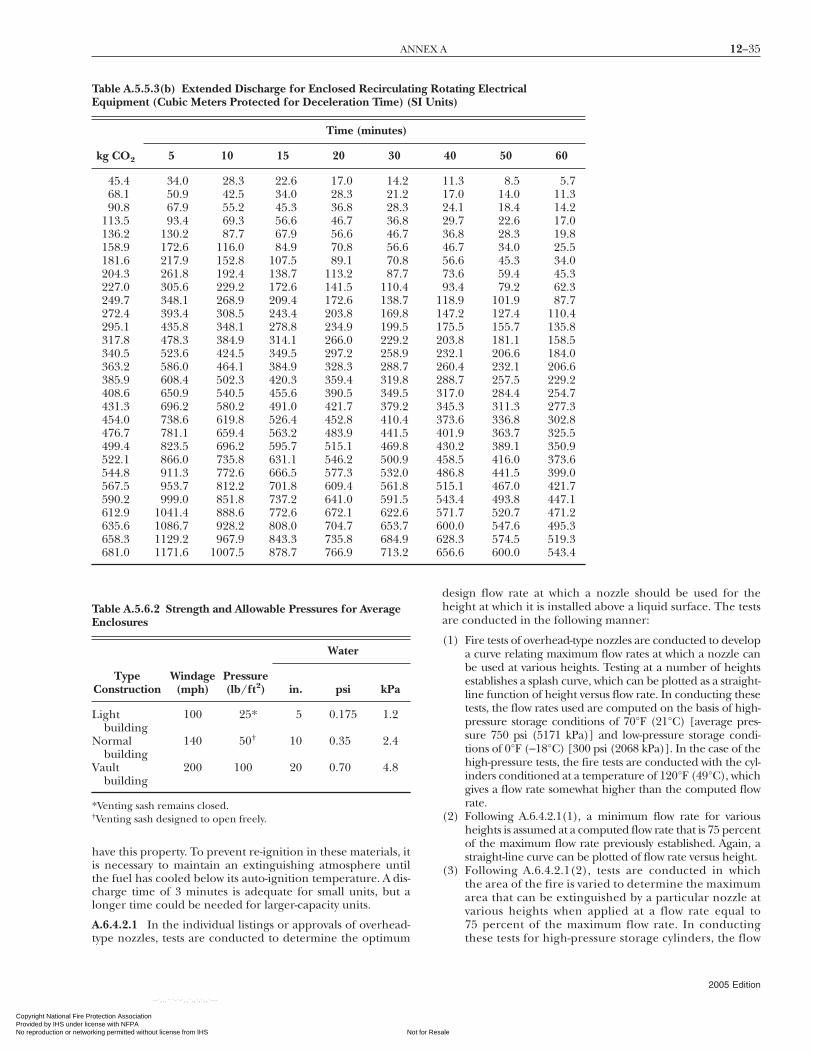
12–35ANNEX A
Copyright National Fire PrProvided by IHS under liceNo reproduction or networ
have this property. To prevent re-ignition in these materials, itis necessary to maintain an extinguishing atmosphere untilthe fuel has cooled below its auto-ignition temperature. A dis-charge time of 3 minutes is adequate for small units, but alonger time could be needed for larger-capacity units.
A.6.4.2.1 In the individual listings or approvals of overhead-
Table A.5.5.3(b) Extended Discharge for Enclosed RecirculatEquipment (Cubic Meters Protected for Deceleration Time) (
Time (minutes)
kg CO2 5 10 15 20 30
45.4 34.0 28.3 22.6 17.0 14.268.1 50.9 42.5 34.0 28.3 21.290.8 67.9 55.2 45.3 36.8 28.3
113.5 93.4 69.3 56.6 46.7 36.8136.2 130.2 87.7 67.9 56.6 46.7158.9 172.6 116.0 84.9 70.8 56.6181.6 217.9 152.8 107.5 89.1 70.8204.3 261.8 192.4 138.7 113.2 87.7227.0 305.6 229.2 172.6 141.5 110.4249.7 348.1 268.9 209.4 172.6 138.7272.4 393.4 308.5 243.4 203.8 169.8295.1 435.8 348.1 278.8 234.9 199.5317.8 478.3 384.9 314.1 266.0 229.2340.5 523.6 424.5 349.5 297.2 258.9363.2 586.0 464.1 384.9 328.3 288.7385.9 608.4 502.3 420.3 359.4 319.8408.6 650.9 540.5 455.6 390.5 349.5431.3 696.2 580.2 491.0 421.7 379.2454.0 738.6 619.8 526.4 452.8 410.4476.7 781.1 659.4 563.2 483.9 441.5499.4 823.5 696.2 595.7 515.1 469.8522.1 866.0 735.8 631.1 546.2 500.9544.8 911.3 772.6 666.5 577.3 532.0567.5 953.7 812.2 701.8 609.4 561.8590.2 999.0 851.8 737.2 641.0 591.5612.9 1041.4 888.6 772.6 672.1 622.6635.6 1086.7 928.2 808.0 704.7 653.7658.3 1129.2 967.9 843.3 735.8 684.9681.0 1171.6 1007.5 878.7 766.9 713.2
Table A.5.6.2 Strength and Allowable Pressures for AverageEnclosures
Water
TypeConstruction
Windage(mph)
Pressure(lb/ft2) in. psi kPa
Lightbuilding
100 25* 5 0.175 1.2
Normalbuilding
140 50† 10 0.35 2.4
Vaultbuilding
200 100 20 0.70 4.8
*Venting sash remains closed.†Venting sash designed to open freely.
type nozzles, tests are conducted to determine the optimum
otection Association nse with NFPA
Not for Resaking permitted without license from IHS
--`,,,```-`-`,,`,,`,`,,`---
design flow rate at which a nozzle should be used for theheight at which it is installed above a liquid surface. The testsare conducted in the following manner:
(1) Fire tests of overhead-type nozzles are conducted to developa curve relating maximum flow rates at which a nozzle canbe used at various heights. Testing at a number of heightsestablishes a splash curve, which can be plotted as a straight-line function of height versus flow rate. In conducting thesetests, the flow rates used are computed on the basis of high-pressure storage conditions of 70°F (21°C) [average pres-sure 750 psi (5171 kPa)] and low-pressure storage condi-tions of 0°F (−18°C) [300 psi (2068 kPa)]. In the case of thehigh-pressure tests, the fire tests are conducted with the cyl-inders conditioned at a temperature of 120°F (49°C), whichgives a flow rate somewhat higher than the computed flowrate.
(2) Following A.6.4.2.1(1), a minimum flow rate for variousheights is assumed at a computed flow rate that is 75 percentof the maximum flow rate previously established. Again, astraight-line curve can be plotted of flow rate versus height.
(3) Following A.6.4.2.1(2), tests are conducted in whichthe area of the fire is varied to determine the maximumarea that can be extinguished by a particular nozzle atvarious heights when applied at a flow rate equal to75 percent of the maximum flow rate. In conducting
tating Electricalts)
40 50 60
11.3 8.5 5.717.0 14.0 11.324.1 18.4 14.229.7 22.6 17.036.8 28.3 19.846.7 34.0 25.556.6 45.3 34.073.6 59.4 45.393.4 79.2 62.318.9 101.9 87.747.2 127.4 110.475.5 155.7 135.803.8 181.1 158.532.1 206.6 184.060.4 232.1 206.688.7 257.5 229.217.0 284.4 254.745.3 311.3 277.373.6 336.8 302.801.9 363.7 325.530.2 389.1 350.958.5 416.0 373.686.8 441.5 399.015.1 467.0 421.743.4 493.8 447.171.7 520.7 471.200.0 547.6 495.328.3 574.5 519.356.6 600.0 543.4
ing RoSI Uni
11122223334444555666
these tests for high-pressure storage cylinders, the flow
2005 Edition
le

12–36 CARBON DIOXIDE EXTINGUISHING SYSTEMS
Copyright National FiProvided by IHS undeNo reproduction or ne
--`,,,```-`-`,,`,,`,`,,`---
rates for the various fires are computed on the basis of70°F (21°C) storage temperature [750 psi (5171 kPa)],and the test cylinders are conditioned to a temperatureof 32°F (0°C).
(4) From the data from A.6.4.2.1(1) through A.6.4.2.1(3), twocurves are plotted. The first is a flow rate versus heightcurve, and the second is an area versus height curve. Thefinal plot of the flow rate versus height curve shows asingle curve established at a flow rate that is 90 percent ofthe maximum flow rate. It is then possible to utilize thisnozzle for various heights at the design flow rate indicatedby this curve or at flow rates slightly above or below thiscurve to allow for differences between computed and ac-tual rates. Typical curves are shown in Figure D.1(a) andFigure D.1(b).
Because these curves are developed on the basis of fire testsutilizing square pans, it is important to remember that thearea coverage for nozzles at various heights shown by the sec-ond curve should be on the basis of approximate square areas.It is also important to remember that these two curves repre-sent the limitations of single-nozzle coverage.
In multiple-nozzle systems, these limitations are used forthe portion of a hazard covered by each individual nozzle.
A.6.4.2.2 For tankside and linear nozzles, fire tests are con-ducted to develop curves relating the maximum and mini-mum flow rates at which a nozzle can be used to the area offire that the nozzle is capable of extinguishing, with additionallimitations regarding maximum width of hazard and spacingrequirements between nozzles and to the nearest corner of ahazard. In these tests, the nozzles are normally installed at adistance of 6 in. (152 mm) above the liquid surface, therebyeliminating the parameter of height. These tests are con-ducted in the following manner.
Single or multiple nozzles are mounted on the edge ofsquare or rectangular pans. In the multiple-nozzle tests,nozzles are mounted on one side or on two opposing sides.Tests are conducted on a number of pan sizes with variousspacing arrangements to establish a maximum rate or splashcurve, which can be plotted as a function of flow rate versusarea covered or hazard width. Following this step, the mini-mum flow rate for various area or hazard width conditions(with other appropriate spacing limitations) is determined bya similar series of tests.
For all of these tests, the flow rates are calculated on thebasis of 0°F (−18°C) storage temperature for low-pressure sys-tems [average pressure 300 psi (2068 kPa)] or 70°F (21°C)storage temperature for high-pressure systems [average pres-sure 750 psi (5171 kPa)]. In high-pressure systems, the actualstorage temperature can vary between 120°F (49°C) and 32°F(0°C). For this reason, the maximum rate or splash rate testsare conducted using storage cylinders conditioned to 120°F(49°C), which gives a flow rate somewhat higher than the com-puted rate. The minimum rate tests are conducted using stor-age cylinders conditioned to 32°F (0°C), which gives a flowrate somewhat lower than the computed rate.
From the data developed from these tests, a plot of flowrate versus area coverage or hazard width is made with themaximum or splash curve reduced by a factor of 10 percentand the minimum rate increased by a factor of 15 percent. Atypical curve for a tankside nozzle is shown by Figure F.1(c),and a curve for a linear nozzle is shown by Figure F.1(d).
A.6.4.3.4 For listing and approval testing, overhead local appli-
cation carbon dioxide nozzles are tested on two-dimensional pan2005 Edition
re Protection Association r license with NFPA
Not fortworking permitted without license from IHS
fires. (See A.6.4.2.1.) Some nozzles have excellent area of cover-age when used on such “flat” fires. Although the actual cone ofdischarge can directly impinge on only a small area of the fire,the carbon dioxide can flow away from the actual area of impactand effectively cover a much larger area of the fire pan.
If the surface on which the carbon dioxide discharge im-pinges is very irregular, it is possible that the nozzle dischargecould not effectively cover all parts of the hazard. If the nozzlesbeing used have small areas of impact compared to their listedareas of coverage, additional nozzles could be necessary to com-pletely cover irregularly shaped objects. Where such irregularlyshaped hazards are to be covered, the designer should be certainthat the number, type, and location of nozzles are sufficient toensure complete coverage of the hazard surfaces. Verifying thecoverage of local application nozzles is an important part of thedischarge test.
A.6.4.4.5 Additional nozzles can be required for this specificpurpose, particularly if stock extends more than 2 ft (0.6 m)above a protected surface.
A.6.5.3.2 Figure A.6.5.3.2 is a graph of the partial enclosure.
A.6.6.2 High-pressure storage temperatures ranging from32°F to 120°F (0°C to 49°C) do not require special methods ofcompensating for changing flow rates.
Where high-pressure storage temperatures can fall below32°F (0°C) or rise above 120°F (49°C), it could be necessary toincorporate special features in the system to ensure properflow rates.
A.7.1.1 A separate carbon dioxide supply can be provided forhand hose line use, or carbon dioxide can be piped from acentral storage unit supplying several hose lines or from fixedmanual or automatic systems. (See 4.6.1.1.)
A.7.1.4 Reference is made to 4.3.1 and A.4.3 regarding haz-ards to personnel due to obscuration of vision and reductionof oxygen concentration below that which will support life,not only in the immediate area of discharge but in adjacent
0.47
5
0.45
0.42
5
0.4
0.25
100
75
50
25
0
0.375 0.50 0.625 0.75 0.875 1.0lb/min·ft3
45403530%
per
imet
er e
nclo
sed
Rate-by-volumeMathematical methodFactor = [% perimeter open (expressed as a decimal) × 0.75] + 0.25
FIGURE A.6.5.3.2 Partial Enclosure Flow Rate Reductionper 6.5.3.2.
areas to which gas can migrate.
Resale

12–37ANNEX B
Copyright National Fire PrProvided by IHS under liceNo reproduction or networ
--`,,,```-`-`,,`,,`,`,,`---
A.7.5.2 The attachment of the discharge nozzle assembly tothe hose by means of a swivel connection is desirable for pro-viding more ease of manipulation.
A.7.5.4 Operation of hand hose line systems depends uponmanual actuation and manual manipulation of a dischargenozzle. Speed and simplicity of operation are therefore essen-tial for successful extinguishment.
A.7.5.4.2 Bleeder valves or similar devices can be utilized toreduce delay in obtaining liquid discharge on low-pressuresystems.
A.8.1.1 The carbon dioxide supply is mounted on a mobilevehicle that can be towed or driven to the scene of a fire andquickly coupled to the standpipe system protecting the in-volved hazard. Mobile supply is primarily fire brigade or firedepartment equipment requiring trained personnel for effec-tive use.
A.8.1.2 Standpipe systems and mobile supply can be usedto supplement complete fixed fire protection systems orcan be used alone for the protection of the specific hazardsas follows:
(1) Mobile supply can be used as a reserve to supplement afixed supply.
(2) Mobile supply can also be outfitted with hand hose linesfor the protection of scattered hazards.
A.8.4.1 Extra quantities could be required to compensate fordelay in getting the mobile supply to the hazard.
A.8.5 The effectiveness of fire protection provided bystandpipe systems and mobile supply depends on the effi-ciency and ability of the manpower that handles the mobilesupply. Generally, this equipment is in the category of firebrigade or fire department equipment requiring a regularlyassigned crew.
A.9.1(2)(c) Examples include spaces containing enginesused for propulsion, engines that drive electrical genera-tors, oil filling stations, cargo pumps, or heating, ventila-tion, and air-conditioning machinery.
A.9.1(2)(d) Carbon dioxide systems are not recommendedfor vehicle spaces that are accessible to passengers.
A.9.2.1 It is intended that NFPA 12, Standard on Carbon DioxideExtinguishing Systems, including this chapter, would be used asa stand-alone document for the design, installation, and main-tenance of marine carbon dioxide systems. Chapter 9 wasadded in 1999 to address marine installations. It was intendedto be used in lieu of other standards such as 46 CFR 119, “Ma-chinery Installations.”
A.9.3.3.2 Except for very small protected spaces noted in9.3.3.1.3, it is the intent of this standard to require two sepa-rate manual operations to cause discharge of a marine system.Provision of a separate manually actuated control for each ofthe discharge control valves required by 9.3.3.1 accomplishesthis intent. This requirement is an exception to the “normalmanual operation” as defined in 4.5.1.2.
A.9.3.3.3 For a high-pressure carbon dioxide system, theemergency manual control for the supply is the manual opera-
tor on the pilot cylinder(s).otection Association nse with NFPA
Not for Resaking permitted without license from IHS
A.9.3.3.5 Sufficient carbon dioxide should be provided topower the alarms at their rated pressure for the required time.
A.9.3.5.1 An example of where drains would be necessarywould be low points in carbon dioxide piping, which are alsoused by a sampling-type smoke detection system.
Fires in cargo spaces may not be completely extinguished bythe carbon dioxide discharge. Whether the fire is completely ex-tinguished or only suppressed depends on a number of factors,including the type and quantity of burning material. Some leak-age of carbon dioxide–enriched atmosphere from the cargohold is likely. Therefore, additional carbon dioxide may need tobe discharged on an intermittent basis to maintain fire suppres-sion in the cargo hold until the vessel reaches port. Once at port,before the cargo hold is opened, properly equipped and trainedfire brigade should be standing by to effect complete extinguish-ment of the burning material.
Annex B Examples of Hazard Protection
This annex is not a part of the requirements of this NFPA documentbut is included for informational purposes only.
B.1 The following annex material is provided to show typicalexamples of how various fire hazards can be protected withfixed carbon dioxide extinguishing systems. It should benoted that the methods described are not to be construed asbeing the only ones that can be used. They are meant to helponly in interpreting and elaborating on the intent of the stan-dard where proper application could be subject to question.
B.2 Commercial/Industrial Food Processing Deep-Fat (HotOil) Cookers. Large deep-fat fryers that are used to continuouslycook food products such as meat, fish, snacks, and so forth,present a fire hazard that requires special attention when design-ing a carbon dioxide extinguishing system to protect them.
If cooking oil is overheated, it will reach its auto-ignitiontemperature before it boils away. Therefore, a fire that in-volves cooking oil vapors can be re-ignited after the initial car-bon dioxide discharge by the high temperature of the hot oilin the cooking vat, unless the oil is cooled below the ignitiontemperature. The energy-efficient design of modern cookingvats makes cooling a slow process.
The arrangement of the equipment to be protected is ofprime consideration to proper system design.
First of all, using the cooker can involve external heating ofthe oil with recirculation of the oil through the cooking vat.This can be considered interexposure. (See 6.2.1.)
Second, some cookers are designed such that the fumehood and conveyor can be raised and lowered by a hydraulicsystem. The combustible food-compatible hydraulic fluidsused present another area of protection and can be consid-ered interexposed. (See 6.2.1.)
Third, there is a concern that a high-production operationwill have an exhaust system that can involve a fume-removalsystem. This concern should be considered part of the hazard.(See 6.2.1.)
The drain board, when subject to oil drippage at the exitend of the conveyor, should be covered. (See 6.2.1.)
Finally, the vat presents the largest area to be protected andthe greatest need for adequate cooling.
B.2.1 Summary of Protection. The following is a quick refer-
ence of protection criteria for system design.2005 Edition
le

12–38 CARBON DIOXIDE EXTINGUISHING SYSTEMS
Copyright National FiProvided by IHS undeNo reproduction or ne
B.2.1.1 Vat. Where the vat has a movable hood, fire protec-tion by total flooding under the hood is not permitted by 5.1.2unless the following criteria are met:
(1) The hood should not be raised during the cooking opera-tion, which means the following:(a) The source of power or fuel to the heating elements is
automatically shut off when the hood is raised (e.g.,for maintenance or cleaning).
(b) A mechanical high-temperature limit switch is em-ployed that will operate any time the temperature ofthe oil is above the preset temperature limit of notmore than 20 percent, in degrees Fahrenheit (de-grees Celsius), above the maximum normal oil oper-ating temperature in degrees Fahrenheit (degreesCelsius). Its operation shall cause the following:
i. Shutoff of power to the oil heater systemii. Prevention of raising electrically operated hoods
iii. Actuation of audible and visual alarms to cau-tion against raising the hood manually
(c) The switch should have an automatic reset tempera-ture not higher than 60°F (33.3°C) below the auto-ignition temperature of the cooking oil.
(2) Before the hood can be raised (e.g., for maintenance andcleaning), a supervised lock-out valve should be closed toprevent the discharge of the carbon dioxide system. Clos-ing of the lock-out valve should actuate the supervisorytrouble alarm on the control unit.
(3) The source of power or fuel to the heating elements isautomatically shut off prior to or simultaneously with thesystem discharge.
(4) The quantity of carbon dioxide and the duration of dis-charge are sufficient to maintain an inert atmosphere inthe vat until the temperature of the cooking oil is loweredto prevent re-ignition per 5.3.5.6. A minimum reductionof 60°F (33.3°C) below the auto-ignition temperature isrecommended.
(5) The system design is based on discharge testing for thespecific fryer model to show compliance with B.2.1.1(4).Documentation of the test should be available upon re-quest by the authority having jurisdiction or the end user.
(6) Thermal detection should actuate the carbon dioxide sys-tem when the temperature is at or below the auto-ignitiontemperature of the cooking oil.
B.2.1.2 Permanent Enclosure. Local application should bedesigned with the hood in the full up position.
B.2.1.3 Drain Board. A local application system using the rate-by-area method per Section 6.4 is appropriate.
B.2.1.4 Fume-Exhaust and Fume-Removal System. Totalflooding designed to a 65 percent concentration per 5.4.2.1 isappropriate.
B.2.1.5 External Oil Heater. A local application system for therecirculating equipment and filters using the rate-by-areamethod (see Section 6.4) or rate-by-volume method (see Section 6.5),depending on the equipment configuration, is appropriate.
B.2.1.6 Hydraulic Oil System. A local application system usingthe rate-by-area method (see Section 6.4) or rate-by-volumemethod (see Section 6.5), depending on the equipment configu-
ration, is appropriate.2005 Edition
re Protection Association r license with NFPA
Not fortworking permitted without license from IHS
--`,,,```-`-`,,`,,`,`,,`---
Because the vat requires a minimum of a 3-minute liquiddischarge (see 6.3.3.5), the carbon dioxide system design canincorporate two discharge piping systems, one for the vat andone for the remaining interexposed hazards.
B.2.1.7 Equipment Shutdown. (See also 4.5.4.8.) Considerationshould also be given to personal safety (see Section 4.3) when thesystem is being designed.
B.3 Restaurant Range Hoods, Connected Ducts, and Associ-ated Hazards. The protection of kitchen range hoods andducts is accomplished with a combination of total floodingand local application systems. The duct or vent stack and theplenum area above the filters can be protected by total flood-ing. The undersurface of the filters and any special hazardssuch as deep-fat fryers can be protected by local application. Itcould be necessary to extend local application protection tocoated underhood surfaces and range surfaces if there is dan-ger of grease accumulation or runoff from the hood or ductunder fire conditions.
In protecting the duct with the recommended flooding fac-tor of 1 lb/8 ft3 (2 kg/m3) of duct volume, a damper is consid-ered essential at either the top or the bottom, with provisionsfor automatic closing at the beginning of the discharge of car-bon dioxide. For ducts that rise to heights greater than 20 ft(6.1 m) or horizontal runs greater than 50 ft (15.3 m), the gasis introduced at intermediate points to ensure proper distribu-tion. With a damper at the top of the stack, a nozzle should beinstalled immediately below, with additional nozzles installedabove if the duct run extends beyond the damper. A nozzle isnormally required in the plenum area.
Nozzles are to be provided to cover the underside of thefilters and to discharge for 30 seconds at the coated surfacerate specified in 6.4.3.5. In lieu of that, the quantity of carbondioxide required and application rates can be determined us-ing special nozzles or methods as could be approved or listedfor this purpose. If the underside of the hood is largely en-closed by a baffle or drip pan, protection can be by total flood-ing using a factor of 1 lb/8 ft3 (2 kg/m3) and compensatingfor open peripheral area. (See 5.3.5.)
Quantities for the protection of deep-fat fryers or otherspecific fire hazards, or both, below the hood are to be inaddition to the preceding requirements. All hazards ventingthrough a common duct should be protected simultaneously.
Automatic fire detection and actuation of the system arerequired for concealed spaces above the filter and in the ductsystem. Detectors should also be provided below filters overany deep-fat cookers.
Visual fire detection and manual actuation (see 4.5.4.4) canbe acceptable for exposed portions of the hazard; however,actuation by either automatic or manual means should dis-charge the complete system. Special attention should be givento the choice of heat detectors, considering normal operatingtemperature level and temperature rise conditions of therange equipment.
Actuation of the system should automatically close damp-ers, shut off forced ventilating fans, and shut off the masterfuel valve or power switch to all cooking equipment associatedwith the hood. These devices should be of the type that re-quires manual resetting. (See 4.5.4.8.)
In addition to normal system maintenance, particular careshould be given to keeping heat detectors and discharge nozzlesclean of grease accumulation. Generally, nozzle seals or caps are
required to keep nozzle orifices free of obstruction.Resale

12–39ANNEX B
Copyright National Fire PrProvided by IHS under liceNo reproduction or networ
For additional information, see NFPA 96, Standard for Venti-lation Control and Fire Protection of Commercial Cooking Operations.
B.4 Newspaper Printing and Rotogravure Presses. Newspaper,rotogravure, and similar presses constitute a substantial hazarddue to the use of highly flammable solvents in the inks, presenceof ink-saturated shredded paper or dust, lubricants, and so forth.In addition to the press units, there can be exhaust ducts, ink-mixing equipment, and associated electrical hazards that requireprotection. Rotogravure presses use more flammable inks thannewspaper printing presses and are equipped with heated dryingdrums or other drying means and constitute a more severe haz-ard. However, the basic protection method for both rotogravureand newspaper presses is the same.
Presses are usually arranged in rows (lines) with foldersinterspersed. The paper can move through the press units tothe folder from either side of the folder. Static electrical sparksare a common source of ignition. Flame spread can be fromthe press units to the folder or from the folder toward thepress units.
Presses are “open” or “closed,” depending on whether mistguards or covers are used. With open-type presses, an exhaustsystem to remove the ink mist is usually required in the pressarrangement, and this exhaust system requires simultaneousprotection.
Press rooms can be protected by total flooding systems;however, local application–type systems are generally used. Al-though the press lines and individual press units constitute aseries of interexposed hazards, subdividing by lines or suitablegrouping within lines is the usual practice for economic rea-sons. Ventilation ducts, ink storage rooms, and control roomsare usually handled by total flooding methods.
Entire press lines can be protected by local applicationmethods. A press line can be subdivided into groups. In allcases, systems should be capable of giving simultaneous andindependent automatic protection to adjacent groups ofother lines and also to in-line groups to which the fire canspread. Protection should be designed so that, if a fire occursnear the junction of adjoining groups, the systems protectingboth groups will discharge simultaneously.
On individual press groups, the rate of carbon dioxide ap-plication can be based on either the rate-by-area or the rate-by-volume method. (See Sections 6.4 and 6.5.)
If the rate-by-area method is used for the presses, the area isbased on the full length of the rolls, including the end frames,and on the full height of the roll stack, including the ink res-ervoir. Both sides of the roll stacks should be included. Colordecks should be similarly calculated. Where outside ink reser-voirs are used, protection is based on the horizontal area ofthe reservoir. The floor area under the press should also beprotected. On rotogravure presses, the dryers and connectingductwork are protected by flooding at 1 lb/8 ft3 (2 kg/m3) tobe discharged in 30 seconds. When using the rate-by-areamethod to determine the amount of carbon dioxide requiredfor folders, carbon dioxide should be applied from both thedrive side and the operating side at two levels. Each nozzle willcover an area 4 ft (1.2 m) wide by 4 ft (1.2 m) high.
When the rate-by-volume method is used, the entire groupof presses to be protected as a section can be considered asone volume. It is not necessary to add 2 ft (0.6 m) to the sidesof each press when the frame constitutes a natural barrier. Asingle folder can be included in this volume; however, adouble-deck folder requires an additional volume block to in-
clude the upper deck.otection Association nse with NFPA
Not for Resaking permitted without license from IHS
--`,,,```-`-`,,`,,`,`,,`---
Nozzles should be located to cover the coated surfaces;however, exact placement according to listings or approvalsmight not be possible. Nozzles should be located to dischargefrom both ends of the press rolls so as to retain the carbondioxide within the press volume. The same applies to folders.Protection should be arranged so as to be effective when themist guards are in place or removed.
The quantity of carbon dioxide required for a single groupis based on discharging at the calculated rate for 30 seconds.The reserve supply should be at least sufficient to protect allthe adjacent groups that could become involved, including areserve for the group in which the fire originates. In high-pressure systems, a single reserve bank can be used as a reservefor several main banks; however, the main bank for one groupcannot be used as the reserve for another group unless specifi-cally approved by the authority having jurisdiction.
All systems should be arranged for automatic actuation withmeans for auxiliary manual actuation. At least one heat detectorshould be located in or over each press unit and folder, depend-ing on the design of the particular unit.
Because of the inherent vibration associated with presses,particular attention should be given to mounting means so asto eliminate vibration damage to tubing or wiring of the detec-tion system.
Immediate detection is particularly important in groupprotection to prevent the spread of fire beyond the group af-fected. Because of the need for rapid detection to prevent firefrom spreading to adjacent groups or operation of adjacentdetectors, or both, the detection system should utilize rate-of-rise, rate-compensated, or equivalent fast-acting detectors.
Complete shutdown of presses, ventilation, pumps, and heatsources simultaneous with system operation is essential.
Audible alarms in the press room and in any basements, pits,or lower levels where carbon dioxide can flow should sound si-multaneously with operation of the system. (See A.4.3.)
In addition to normal system maintenance, particular careshould be given to ensuring continuance of proper nozzle lo-cation and alignment during normal press maintenance pro-cedures. Special attention should also be given to effects ofpress vibration on heat actuators and connecting tubing orwiring.
B.5 Open-Top Pits. Open pits up to 4 ft (1.2 m) deep or up toa depth equal to one-quarter the width, whichever is greater,should be protected on the basis of local application. The areato be considered in determining the quantity of carbon diox-ide is the total floor area of the pit less any area covered by asimultaneously protected tank or other equipment for whichthe quantity is separately calculated. Nozzles are located so asto provide coverage of the protected area in accordance withlisting or approval data. It could thus be necessary to locateadditional nozzles in the center of the pit.
Open pits that exceed 4 ft (1.2 m) in depth or a depthequal to one-quarter the width, whichever is greater, can beprotected on an area basis using a discharge rate of 4 lb/min·ft2 (19.5 kg/min·m2) of floor area and a discharge timeof 30 seconds. The nozzles can be located around the sides ofthe pit so as to apply the carbon dioxide uniformly from allsides. Care should be taken to use the appropriate number ofnozzles that have sufficient projection so as to reach the centerareas of large pits. Alternately, it could be preferable to locatesome of the nozzles so as to discharge directly on equipmentin the pit requiring protection, such as pumps, motors, or
other critical items. Open-top dip tanks should be protected2005 Edition
le
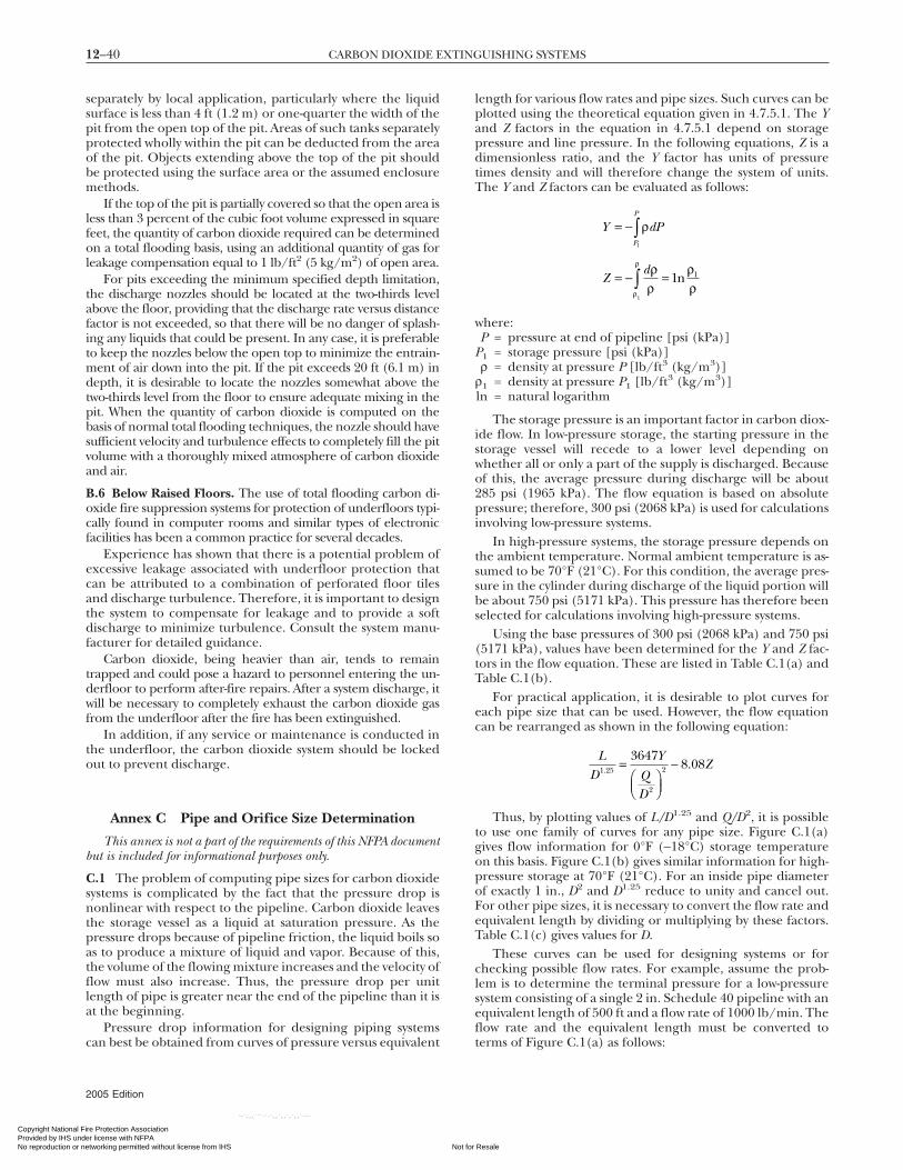
12–40 CARBON DIOXIDE EXTINGUISHING SYSTEMS
Copyright National FiProvided by IHS undeNo reproduction or ne
separately by local application, particularly where the liquidsurface is less than 4 ft (1.2 m) or one-quarter the width of thepit from the open top of the pit. Areas of such tanks separatelyprotected wholly within the pit can be deducted from the areaof the pit. Objects extending above the top of the pit shouldbe protected using the surface area or the assumed enclosuremethods.
If the top of the pit is partially covered so that the open area isless than 3 percent of the cubic foot volume expressed in squarefeet, the quantity of carbon dioxide required can be determinedon a total flooding basis, using an additional quantity of gas forleakage compensation equal to 1 lb/ft2 (5 kg/m2) of open area.
For pits exceeding the minimum specified depth limitation,the discharge nozzles should be located at the two-thirds levelabove the floor, providing that the discharge rate versus distancefactor is not exceeded, so that there will be no danger of splash-ing any liquids that could be present. In any case, it is preferableto keep the nozzles below the open top to minimize the entrain-ment of air down into the pit. If the pit exceeds 20 ft (6.1 m) indepth, it is desirable to locate the nozzles somewhat above thetwo-thirds level from the floor to ensure adequate mixing in thepit. When the quantity of carbon dioxide is computed on thebasis of normal total flooding techniques, the nozzle should havesufficient velocity and turbulence effects to completely fill the pitvolume with a thoroughly mixed atmosphere of carbon dioxideand air.
B.6 Below Raised Floors. The use of total flooding carbon di-oxide fire suppression systems for protection of underfloors typi-cally found in computer rooms and similar types of electronicfacilities has been a common practice for several decades.
Experience has shown that there is a potential problem ofexcessive leakage associated with underfloor protection thatcan be attributed to a combination of perforated floor tilesand discharge turbulence. Therefore, it is important to designthe system to compensate for leakage and to provide a softdischarge to minimize turbulence. Consult the system manu-facturer for detailed guidance.
Carbon dioxide, being heavier than air, tends to remaintrapped and could pose a hazard to personnel entering the un-derfloor to perform after-fire repairs. After a system discharge, itwill be necessary to completely exhaust the carbon dioxide gasfrom the underfloor after the fire has been extinguished.
In addition, if any service or maintenance is conducted inthe underfloor, the carbon dioxide system should be lockedout to prevent discharge.
Annex C Pipe and Orifice Size Determination
This annex is not a part of the requirements of this NFPA documentbut is included for informational purposes only.
C.1 The problem of computing pipe sizes for carbon dioxidesystems is complicated by the fact that the pressure drop isnonlinear with respect to the pipeline. Carbon dioxide leavesthe storage vessel as a liquid at saturation pressure. As thepressure drops because of pipeline friction, the liquid boils soas to produce a mixture of liquid and vapor. Because of this,the volume of the flowing mixture increases and the velocity offlow must also increase. Thus, the pressure drop per unitlength of pipe is greater near the end of the pipeline than it isat the beginning.
Pressure drop information for designing piping systems
can best be obtained from curves of pressure versus equivalent2005 Edition
re Protection Association r license with NFPA
Not fortworking permitted without license from IHS
--`,,,```-`-`,,`,,`,`,,`---
length for various flow rates and pipe sizes. Such curves can beplotted using the theoretical equation given in 4.7.5.1. The Yand Z factors in the equation in 4.7.5.1 depend on storagepressure and line pressure. In the following equations, Z is adimensionless ratio, and the Y factor has units of pressuretimes density and will therefore change the system of units.The Y and Z factors can be evaluated as follows:
Y dP
Zd
P
P
= −
= − =
∫
∫
ρ
ρρ
ρρρ
ρ
1
1
1 1n
where:P = pressure at end of pipeline [psi (kPa)]
P1 = storage pressure [psi (kPa)]ρ = density at pressure P [lb/ft3 (kg/m3)]
ρ1 = density at pressure P1 [lb/ft3 (kg/m3)]ln = natural logarithm
The storage pressure is an important factor in carbon diox-ide flow. In low-pressure storage, the starting pressure in thestorage vessel will recede to a lower level depending onwhether all or only a part of the supply is discharged. Becauseof this, the average pressure during discharge will be about285 psi (1965 kPa). The flow equation is based on absolutepressure; therefore, 300 psi (2068 kPa) is used for calculationsinvolving low-pressure systems.
In high-pressure systems, the storage pressure depends onthe ambient temperature. Normal ambient temperature is as-sumed to be 70°F (21°C). For this condition, the average pres-sure in the cylinder during discharge of the liquid portion willbe about 750 psi (5171 kPa). This pressure has therefore beenselected for calculations involving high-pressure systems.
Using the base pressures of 300 psi (2068 kPa) and 750 psi(5171 kPa), values have been determined for the Y and Z fac-tors in the flow equation. These are listed in Table C.1(a) andTable C.1(b).
For practical application, it is desirable to plot curves foreach pipe size that can be used. However, the flow equationcan be rearranged as shown in the following equation:
LD
Y
QD
Z1 25
2
2
36478 08. .=
⎛⎝⎜
⎞⎠⎟
−
Thus, by plotting values of L/D1.25 and Q/D2, it is possibleto use one family of curves for any pipe size. Figure C.1(a)gives flow information for 0°F (−18°C) storage temperatureon this basis. Figure C.1(b) gives similar information for high-pressure storage at 70°F (21°C). For an inside pipe diameterof exactly 1 in., D2 and D1.25 reduce to unity and cancel out.For other pipe sizes, it is necessary to convert the flow rate andequivalent length by dividing or multiplying by these factors.Table C.1(c) gives values for D.
These curves can be used for designing systems or forchecking possible flow rates. For example, assume the prob-lem is to determine the terminal pressure for a low-pressuresystem consisting of a single 2 in. Schedule 40 pipeline with anequivalent length of 500 ft and a flow rate of 1000 lb/min. Theflow rate and the equivalent length must be converted to
terms of Figure C.1(a) as follows:Resale

12–41ANNEX C
Copyright National Fire PrProvided by IHS under liceNo reproduction or networ
--`,,,```-`-`,,`,,`,`,,`---
QD
D
LD
D
22
1 251 25
10004 28
234
5002 48
201
= =
= =
.
...
lb/min
ft
⋅
⋅
From Figure C.1(a), the terminal pressure is found to beabout 228 psi at the point where the interpolated flow rate of234 lb/min intersects the equivalent length scale at 201 ft.
If this line terminates in a single nozzle, the equivalent ori-fice area must be matched to the terminal pressure in order tocontrol the flow rate at the desired level of 1000 lb/min. Re-ferring to Table 4.7.5.2.1, it will be noted that the dischargerate will be 1410 lb/min·in.2 of equivalent orifice area whenthe orifice pressure is 230 psi. The required equivalent orificearea of the nozzle is thus equal to the total flow rate divided bythe rate per square inch as shown in the following equation.
Equivalent orifice area lb/min
lb/min in.
2= =1000
14100 709
⋅. iin.2
From a practical viewpoint, the designer would select astandard nozzle having an equivalent area nearest to the com-puted area. If the orifice area happened to be a little larger,the actual flow rate would be slightly higher and the terminalpressure would be somewhat lower than the estimated 228 psi(1572 kPa).
If, in the previous example, instead of terminating with onelarge nozzle, the pipeline branched into two smaller pipelines,it would be necessary to determine the pressure at the end ofeach branch line. To illustrate this procedure, assume that thebranch lines are equal and consist of 11⁄2 in. Schedule 40 pipewith equivalent lengths of 200 ft (61 m) and the flow in eachbranch line is to be 500 lb/min (227 kg/min). Converting toterms used in Figure C.1(a), the following equations result:
QD
D
LD
D
22
1 251 25
5002 592
193
2001 813
110
= =
= =
.
...
lb/min
ft
⋅
⋅
Table C.1(a) Values of Y and Z for 300 psi Initial Storage Pres
Pressure(psi) Z 0 1 2 3
300 0.000 0 0 0 0290 0.135 596 540 483 426280 0.264 1119 1070 1020 969270 0.387 1580 1536 1492 1448260 0.505 1989 1950 1911 1871250 0.620 2352 2318 2283 2248240 0.732 2677 2646 2615 2583230 0.841 2968 2940 2912 2884220 0.950 3228 3204 3179 3153210 1.057 3462 3440 3418 3395200 1.165 3673 3653 3632 3612190 1.274 3861 3843 3825 3807180 1.384 4030 4014 3998 3981170 1.497 4181 4167 4152 4138160 1.612 4316 4303 4291 4277150 1.731 4436 4425 4413 4402
otection Association nse with NFPA
Not for Resaking permitted without license from IHS
From Figure C.1(a), the starting pressure of 228 psi(1572 kPa) (terminal pressure of main line) intersects theflow rate line [193 lb/min (87.6 kg/min)] at an equivalentlength of about 300 ft (91.4 m). In other words, if thebranch line started at the storage vessel, the liquid carbondioxide would have to flow through 300 ft (91.4 m) of pipe-line before the pressure dropped to 228 psi (1572 kPa).This length thus becomes the starting point for the equiva-lent length of the branch line. The terminal pressure of thebranch line is then found to be 165 psi (1138 kPa) at thepoint where the 193 lb/min (87.6 kg/min) flow rate lineintersects the total equivalent length line of 410 ft (125 m),or 300 ft + 110 ft (91 m + 34 m). With this new terminalpressure [165 psi (1138 kPa)] and flow rate [500 lb/min(227 kg/min)], the required equivalent nozzle area at theend of each branch line will be approximately 0.567 in.2
(366 mm2). This is about the same as the single large nozzleexample, except that the discharge rate is cut in half due tothe reduced pressure.
The design of the piping distribution system is based on theflow rate desired at each nozzle. This in turn determines therequired flow rate in the branch lines and the main pipeline.From practical experience, it is possible to estimate the ap-proximate pipe sizes required. The pressure at each nozzlecan be determined from suitable flow curves. The nozzle ori-fice sizes are then selected on the basis of nozzle pressure fromthe data given in 4.7.5.2.
In high-pressure systems, the main header is supplied by anumber of separate cylinders. The total flow is thus divided bythe number of cylinders to obtain the flow rate from eachcylinder. The flow capacity of the cylinder valve and the con-nector to the header vary with each manufacturer, dependingon design and size. For any particular valve, dip tube, andconnector assembly, the equivalent length can be determinedin terms of feet of standard pipe size. With this information,the flow equation can be used to prepare a curve of flow rateversus pressure drop. This curve provides a convenientmethod of determining header pressure for a specific valve
Y
4 5 6 7 8 9
0 0 0 0 0 0367 308 248 187 126 63918 866 814 760 706 652
1402 1357 1310 1263 1216 11681831 1790 1749 1708 1666 16232212 2176 2139 2102 2065 20272552 2519 2487 2454 2420 23862855 2826 2797 2768 2738 27083128 3102 3075 3049 3022 29953372 3349 3325 3301 3277 32533591 3570 3549 3528 3506 34853788 3769 3750 3731 3712 36923965 3948 3931 3914 3896 38794123 4108 4093 4077 4062 40464264 4251 4237 4223 4210 41964390 4378 4366 4354 4351 4329
sure
and connector combination.
2005 Edition
le

12–42 CARBON DIOXIDE EXTINGUISHING SYSTEMS
Copyright National FiProvided by IHS undeNo reproduction or ne
Table C.1(b) Values of Y and Z for 750 psi Initial Storage Pressure
Y
Pressure(psi) Z 0 1 2 3 4 5 6 7 8 9
750 0.000 0 0 0 0 0 0 0 0 0 0740 0.038 497 448 399 350 300 251 201 151 101 51730 0.075 975 928 881 833 786 738 690 642 594 545720 0.110 1436 1391 1345 1299 1254 1208 1161 1115 1068 1022710 0.143 1882 1838 1794 1750 1706 1661 1616 1572 1527 1481700 0.174 2314 2271 2229 2186 2143 2100 2057 2013 1970 1926
690 0.205 2733 2691 2650 2608 2567 2525 2483 2441 2399 2357680 0.235 3139 3099 3059 3018 2978 2937 2897 2856 2815 2774670 0.265 3533 3494 3455 3416 3377 3338 3298 3259 3219 3179660 0.296 3916 3878 3840 3802 3764 3726 3688 3649 3611 3572650 0.327 4286 4250 4213 4176 4139 4102 4065 4028 3991 3953640 0.360 4645 4610 4575 4539 4503 4467 4431 4395 4359 4323
630 0.393 4993 4959 4924 4890 4855 4821 4786 4751 4716 4681620 0.427 5329 5296 5263 5229 5196 5162 5129 5095 5061 5027610 0.462 5653 5621 5589 5557 5525 5493 5460 5427 5395 5362600 0.498 5967 5936 5905 5874 5843 5811 5780 5749 5717 5685590 0.535 6268 6239 6209 5179 6149 6119 6089 6058 6028 5997580 0.572 6560 6531 6502 6473 6444 6415 6386 6357 6328 6298
570 0.609 6840 6812 6785 6757 6729 6701 6673 6645 6616 6588560 0.646 7110 7084 7057 7030 7003 6976 6949 6922 6895 6868550 0.683 7371 7345 7320 7294 7268 7242 7216 7190 7163 7137540 0.719 7622 7597 7572 7548 7523 7498 7472 7447 7422 7396530 0.756 7864 7840 7816 7792 7768 7744 7720 7696 7671 7647520 0.792 8098 8075 8052 8028 8005 7982 7958 7935 7911 7888
510 0.827 8323 8301 8278 8256 8234 8211 8189 8166 8143 8120500 0.893 8540 8519 8497 8476 8454 8433 8411 8389 8367 8345490 0.898 8750 8730 8709 8688 8667 8646 8625 8604 8583 8562480 0.933 8953 8933 8913 8893 8873 8852 8832 8812 8791 8771470 0.967 9149 9129 9110 9091 9071 9052 9032 9012 8993 8973460 1.002 9338 9319 9301 9282 9263 9244 9225 9206 9187 9168
450 1.038 9520 9502 9484 9466 9448 9430 9412 9393 9375 9356440 1.073 9697 9697 9662 9644 9627 9609 9592 9574 9556 9538430 1.109 9866 9850 9833 9816 9799 9782 9765 9748 9731 9714420 1.146 10030 10014 9998 9982 9966 9949 9933 9916 9900 9883410 1.184 10188 10173 10157 10141 10126 10110 10094 10078 10062 10046400 1.222 10340 10325 10310 10295 10280 10265 10250 10234 10219 10204
390 1.262 10486 10472 10458 10443 10429 10414 10399 10385 10370 10355380 1.302 10627 10613 10599 10585 10571 10557 10543 10529 10515 10501370 1.344 10762 10749 10735 10722 10708 10695 10681 10668 10654 10641360 1.386 10891 10878 10866 10853 10840 10827 10814 10801 10788 10775350 1.429 11015 11003 10991 10978 10966 10954 10941 10929 10916 10904340 1.473 11134 11122 11110 11099 11087 11075 11063 11051 11039 11027
330 1.518 11247 11236 11225 11214 11202 11191 11180 11168 11157 11145320 1.564 11356 11345 11334 11323 11313 11302 11291 11280 11269 11258310 1.610 11459 11449 11439 11428 11418 11408 11398 11387 11377 11366300 1.657 11558 11548 11539 11529 11519 11509 11499 11489 11469 11469
2005 Edition
re Protection Association r license with NFPA
Not for Resaletworking permitted without license from IHS
--`,,,```-`-`,,`,,`,`,,`---

12–43ANNEX C
Copyright National Fire PrProvided by IHS under liceNo reproduction or networ
For SI units, 1 psi = 6.89 kPa; 1 lb/min = 0.454 kg/min.
Equivalent length
Diameter1.25
LD1.25
100080060040030020010050 15000
=
600
500450400
350
300
250
700800
200180
100
90
80
160140
120
Q/D 2 = 70 lb/min
Carbon dioxide flow0°F (–18°C) storage
(Q = flow)
Ter
min
al p
ress
ure
(psi
)300
290
280
270
260
250
240
100
150
180
200
220
230
FIGURE C.1(a) Pressure Drop in Pipeline for 300 psi (2068 kPa) Storage Pressure.
For SI units, 1 psi = 6.89 kPa; 1 lb/min = 0.454 kg/min.
Equivalent length
Diameter1.25
LD1.25
100080060040030020010050 15000
=
Ter
min
al p
ress
ure
(psi
)
200
300
400
450
500
550
600
800700
600
500450
400
350
300
250
200
180
160
140
120
650
700
750
Carbon dioxide flow70°F (21°C) storage
(Q = flow)Q/D 2
= 100 lb/min
FIGURE C.1(b) Pressure Drop in Pipeline for 750 psi (5171 kPa) Storage Pressure.
2005 Edition
otection Association nse with NFPA
Not for Resaleking permitted without license from IHS
--`,,,```-`-`,,`,,`,`,,`---

12–44 CARBON DIOXIDE EXTINGUISHING SYSTEMS
Copyright National FiProvided by IHS undeNo reproduction or ne
Table C.1(d) and Table C.1(e) list the equivalent lengths ofpipe fittings for determining the equivalent length of pipingsystems. Table C.1(d) is for threaded joints, and Table C.1(e)is for welded joints. Both tables were computed for Schedule40 pipe sizes; however, for all practical purposes, the samefigures can also be used for Schedule 80 pipe sizes.
able C.1(c) Values of D1.25 and D2 for Various Pipe Sizes
Pipe Sizeand Type
Inside Diameter(in.) D1.25 D2
1⁄2 Std. 0.622 0.5521 0.38691⁄4 Std. 0.824 0.785 0.6791 Std. 1.049 1.0615 1.1001 XH 0.957 0.9465 0.9158
11⁄4 Std. 1.380 1.496 1.90411⁄4 XH 1.278 1.359 1.63311⁄2 Std. 1.610 1.813 2.59211⁄2 XH 1.500 1.660 2.2502 Std. 2.067 2.475 4.2722 XH 1.939 2.288 3.760
21⁄2 Std. 2.469 3.09 6.09621⁄2 XH 2.323 2.865 5.3963 Std. 3.068 4.06 9.4133 XH 2.900 3.79 8.4104 Std. 4.026 5.71 16.214 XH 3.826 5.34 14.645 Std. 5.047 7.54 25.475 XH 4.813 7.14 23.166 Std. 6.065 9.50 36.786 XH 5.761 8.92 33.19
Table C.1(d) Equivalent Lengths in Feet of Threaded PipeFitting
PipeSize(in.)
ElbowStd. 45
Degrees
ElbowStd. 90
Degrees
Elbow90 Degrees
Long Radiusand Tee
Thru FlowTeeSide
UnionCouplingor GateValve
3⁄8 0.6 1.3 0.8 2.7 0.31⁄2 0.8 1.7 1.0 3.4 0.43⁄4 1.0 2.2 1.4 4.5 0.51 1.3 2.8 1.8 5.7 0.6
11⁄4 1.7 3.7 2.3 7.5 0.811⁄2 2.0 4.3 2.7 8.7 0.92 2.6 5.5 3.5 11.2 1.2
21⁄2 3.1 6.6 4.1 13.4 1.43 3.8 8.2 5.1 16.6 1.84 5.0 10.7 6.7 21.8 2.45 6.3 13.4 8.4 27.4 3.06 7.6 16.2 10.1 32.8 3.5
For SI units, 1 ft = 0.3048 m.
2005 Edition
re Protection Association r license with NFPA
Not fortworking permitted without license from IHS
--`,,
For nominal changes in elevation of piping, the changein head pressure is negligible. However, if there is a substan-tial change in elevation, this factor should be taken intoaccount. The head pressure correction per foot of elevationdepends on the average line pressure where the elevationtakes place because the density changes with pressure. Cor-rection factors are given in Table C.1(f) and Table C.1(g)for low-pressure and high-pressure systems, respectively.The correction is subtracted from the terminal pressurewhen the flow is upward and is added to the terminal pres-sure when the flow is downward.
Table C.1(f) Elevation Correction Factors for Low-PressureSystem
Average Line Pressure Elevation Correction
psi kPa psi/ft kPa/m
300 2068 0.443 10.00280 1930 0.343 7.76260 1792 0.265 5.99240 1655 0.207 4.68220 1517 0.167 3.78200 1379 0.134 3.03180 1241 0.107 2.42160 1103 0.085 1.92140 965 0.067 1.52
Table C.1(e) Equivalent Lengths in Feet of Welded PipeFitting
PipeSize(in.)
ElbowStd. 45
Degrees
ElbowStd. 90
Degrees
Elbow90 Degrees
Long Radiusand Tee
Thru FlowTeeSide
GateValve
3⁄8 0.2 0.7 0.5 1.6 0.31⁄2 0.3 0.8 0.7 2.1 0.43⁄4 0.4 1.1 0.9 2.8 0.51 0.5 1.4 1.1 3.5 0.6
11⁄4 0.7 1.8 1.5 4.6 0.811⁄2 0.8 2.1 1.7 5.4 0.92 1.0 2.8 2.2 6.9 1.2
21⁄2 1.2 3.3 2.7 8.2 1.43 3.8 4.1 3.3 10.2 1.84 2.0 5.4 4.4 13.4 2.45 2.5 6.7 5.5 16.8 3.06 3.0 8.1 6.6 20.2 3.5
For SI units, 1 ft = 0.3048 m.
T
Resale
,```-`-`,,`,,`,`,,`---

12–45ANNEX D
Copyright National Fire PrProvided by IHS under liceNo reproduction or networ
Annex D Total Flooding Systems
This annex is not a part of the requirements of this NFPA documentbut is included for informational purposes only.
D.1 From a performance viewpoint, a total flooding system isdesigned to develop a carbon dioxide concentration that willextinguish fires in combustible materials located in an en-closed space. It should also maintain an effective concentra-tion until the maximum temperature has been reduced belowthe re-ignition point.
For many materials, there can be a need to maintain a con-centration of carbon dioxide to allow for cooling. Sheet metalducting that can be heated quickly and substantially is an ex-ample of where maintaining the concentration for coolingcan be necessary.
The concentration of carbon dioxide required will de-pend on the type of combustible material involved. Theconcentration of carbon dioxide has been accurately deter-mined for most surface-type fires, particularly those involv-ing liquids and gases. Most of this information has beenobtained by the U.S. Bureau of Mines. For deep-seatedfires, the critical concentration required for extinguish-ment is less definite and has in general been established bypractical test work.
The volume of carbon dioxide required to develop agiven concentration will be greater than the final volumeremaining in the enclosure. In most cases, carbon dioxideshould be applied in a manner that promotes progressivemixing of the atmosphere. The displaced atmosphere is ex-hausted freely from the enclosure through various smallopenings or through special vents, as carbon dioxide is in-jected. Some carbon dioxide is therefore lost with thevented atmosphere. This loss becomes greater at high con-centrations. This method of application is called free-effluxflooding.
Under the above conditions, the volume of carbon dioxiderequired to develop a given concentration in the atmosphereis expressed by the following equations:
e x =−100
100 2%CO
Table C.1(g) Elevation Correction Factors for High-PressureSystem
Average Line Pressure Elevation Correction
psi kPa psi/ft kPa/m
750 5171 0.352 7.96700 4826 0.300 6.79650 4482 0.255 5.77600 4137 0.215 4.86550 3792 0.177 4.00500 3447 0.150 3.39450 3103 0.125 2.83400 2758 0.105 2.38350 2413 0.085 1.92300 268 0.070 1.58
or
otection Association nse with NFPA
Not for Resaking permitted without license from IHS
--`,,,```-`-`,,`,,`,`,,`---
X =−
2.303log%CO10
2
100100
where:X = volume of carbon dioxide added per volume of
spacee = 2.718 (natural logarithm base)
From the preceding equations, the volume of carbondioxide required to develop a given concentration can becalculated. This quantity of carbon dioxide can be ex-pressed in terms of cubic feet (cubic meters) of space pro-tected per pound (kilogram) of carbon dioxide or pounds(kilograms) of carbon dioxide per 100 ft3 (0.28 m3). Theseresults have been calculated and plotted for easy reference.
One such curve is shown on Figure D.1(a). On thiscurve, it was assumed that the carbon dioxide would expandto a volume of 9 ft3/lb (0.56 m3/kg) at a temperature of86°F (30°C). The top curve (complete displacement) andthe bottom curve (no efflux) are theoretical extremes plot-ted for comparative purposes only. The middle curve (freeefflux), the curve to be used, must be tempered by propersafety factors. Similar information is also given on Fig-ure D.1(b) in the form of a nomograph. Column A showsoxygen content of air–carbon dioxide mixtures; Column Bshows weights of carbon dioxide in air–carbon dioxide mix-tures; and Column C shows cubic feet per pound of carbondioxide in air–carbon dioxide mixtures. In this case, it wasassumed that the final temperature would be about 50°F(10°C), giving a volume of 8.35 ft3/lb (0.52 m3/kg) of car-bon dioxide. The nomograph therefore indicates some-what greater quantities of carbon dioxide for the same con-centration. The data in Chapters 4 through 6 are based onan expansion of 9 ft3/lb (0.56 m3/kg) of carbon dioxide. Itshould be noted that, in some well-insulated enclosures,such as freezers and anechoic test chambers, complete andrapid vaporization of the carbon dioxide discharge mightnot occur. For unusual cases like these, the manufacturershould be consulted.
The time required for cooling below the re-ignitionpoint depends on the type of fire and the insulating effectof the combustible material. For surface-type fires, it can beassumed that the fire will be extinguished almost as soon asthe desired concentration is obtained. The enclosureshould, of course, retain a reasonable concentration forsome time after the carbon dioxide has been injected,which provides an additional factor of safety.
For deep-seated fires, the concentration should be main-tained for a longer period of time because the hot materialwill cool off slowly. The cooling time will vary considerably,depending on the nature of the material. Because the cool-ing time will tend to be long, it is necessary to give consid-erable attention to the problem of maintaining the extin-guishing concentration. Surface fires and deep-seated firesare basically different and should be approached withsomewhat different objectives in mind.
Examples of hazards protected by total flooding systemsinclude rooms, vaults, enclosed machines, ducts, ovens, con-tainers, and the contents thereof.
2005 Edition
le

12–46 CARBON DIOXIDE EXTINGUISHING SYSTEMS
Copyright National FiProvided by IHS undeNo reproduction or ne
--`,,,```-`-`,,`,,`,`,,`---
For SI units, 1 ft3/lb = 0.0624 m3/kg.
Oxygen remaining (%)0 1 2 3 4 5 6 7 8 9 10
Inje
ctio
n fa
ctor
(ft3 /lb
CO
2)CO2 received (%)
100 95 90 85 80 75 70 65 60 55 530
29
28
27
26
25
24
23
22
21
20
19
18
17
16
15
14
13
12
11
10
9
8
7
6
5
4
3
2
FIGURE D.1(a) Carbon Dioxide Requirements for Inert Atmcarbon dioxide expansion of 9 ft3/lb (0.56 m3/kg)].
11 12 13 14 15 16
0 45 40 35 30 25
CO
2 in
ject
ed (
%)
450
300
200
150140130120110100
90
80
70
60585654525048
46
44
42
40
38
36
34
32
30
ospheres [based on a
2005 Edition
re Protection Association r license with NFPA
Not for Resaletworking permitted without license from IHS
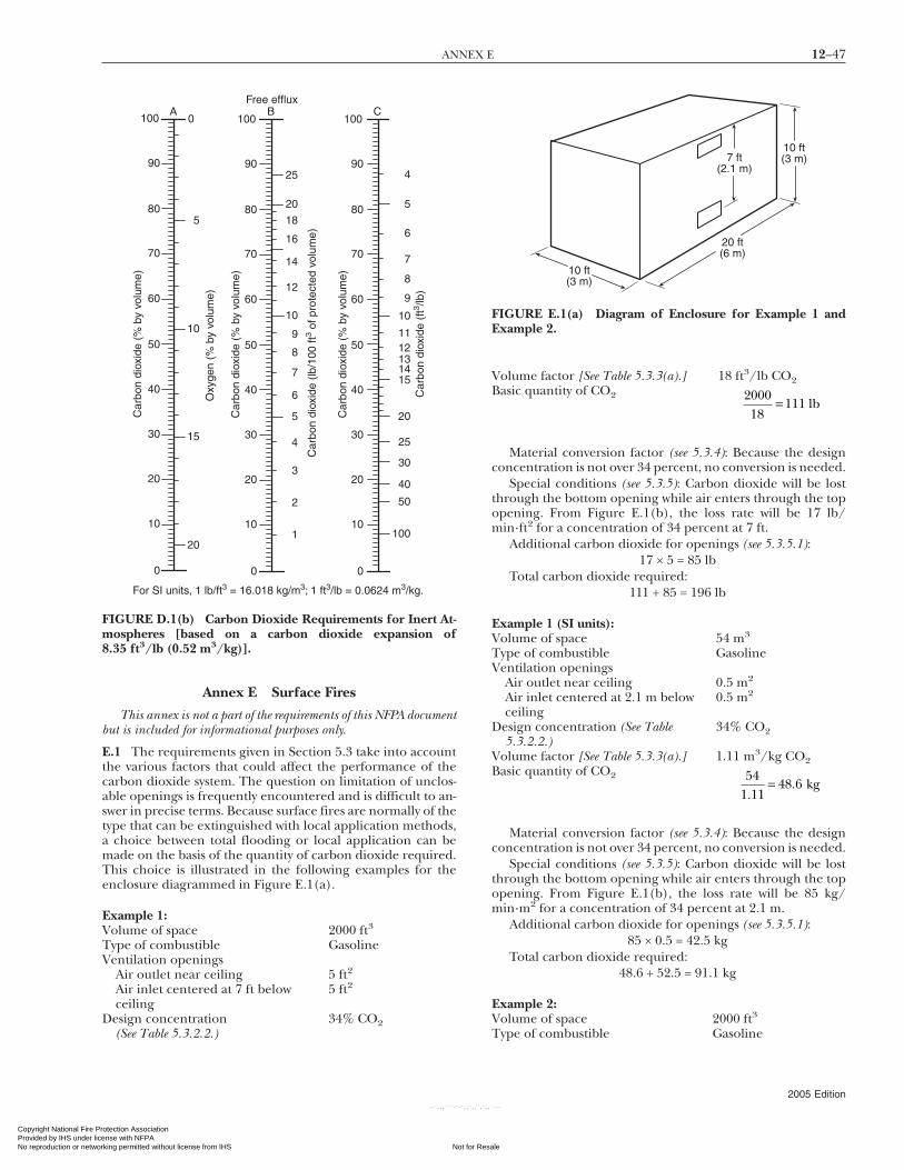
12–47ANNEX E
Copyright National Fire PrProvided by IHS under liceNo reproduction or networ
Annex E Surface Fires
This annex is not a part of the requirements of this NFPA documentbut is included for informational purposes only.
E.1 The requirements given in Section 5.3 take into accountthe various factors that could affect the performance of thecarbon dioxide system. The question on limitation of unclos-able openings is frequently encountered and is difficult to an-swer in precise terms. Because surface fires are normally of thetype that can be extinguished with local application methods,a choice between total flooding or local application can bemade on the basis of the quantity of carbon dioxide required.This choice is illustrated in the following examples for theenclosure diagrammed in Figure E.1(a).
Example 1:Volume of space 2000 ft3
Type of combustible GasolineVentilation openings
Air outlet near ceiling 5 ft2
Air inlet centered at 7 ft belowceiling
5 ft2
Design concentration(See Table 5.3.2.2.)
34% CO2
For SI units, 1 lb/ft3 = 16.018 kg/m3; 1 ft3/lb = 0.0624 m3/kg.
Car
bon
diox
ide
(% b
y vo
lum
e)
Oxy
gen
(% b
y vo
lum
e)
Car
bon
diox
ide
(% b
y vo
lum
e)
Car
bon
diox
ide
(lb/1
00 ft
3 of p
rote
cted
vol
ume)
Car
bon
diox
ide
(% b
y vo
lum
e)
Car
bon
diox
ide
(ft3 /lb
)
Free efflux
100
90
80
70
60
50
40
30
20
10
0
100
90
80
70
60
50
40
30
20
10
0
100
90
80
70
60
50
40
30
20
10
0
A B C0
5
10
15
20 1
2
3
4
5
6
7
8
9
10
12
14
16
18
20
25
100
50
40
30
25
20
15 14 13 12 11
10
9
8
7
6
5
4
FIGURE D.1(b) Carbon Dioxide Requirements for Inert At-mospheres [based on a carbon dioxide expansion of8.35 ft3/lb (0.52 m3/kg)].
otection Association nse with NFPA
Not for Resaking permitted without license from IHS
--`,,,```-`-`,,`,,`,`,,`
Volume factor [See Table 5.3.3(a).] 18 ft3/lb CO2Basic quantity of CO2 2000
18111= lb
Material conversion factor (see 5.3.4): Because the designconcentration is not over 34 percent, no conversion is needed.
Special conditions (see 5.3.5): Carbon dioxide will be lostthrough the bottom opening while air enters through the topopening. From Figure E.1(b), the loss rate will be 17 lb/min·ft2 for a concentration of 34 percent at 7 ft.
Additional carbon dioxide for openings (see 5.3.5.1):17 × 5 = 85 lb
Total carbon dioxide required:111 + 85 = 196 lb
Example 1 (SI units):Volume of space 54 m3
Type of combustible GasolineVentilation openings
Air outlet near ceiling 0.5 m2
Air inlet centered at 2.1 m belowceiling
0.5 m2
Design concentration (See Table5.3.2.2.)
34% CO2
Volume factor [See Table 5.3.3(a).] 1.11 m3/kg CO2Basic quantity of CO2 54
1 1148 6
..= kg
Material conversion factor (see 5.3.4): Because the designconcentration is not over 34 percent, no conversion is needed.
Special conditions (see 5.3.5): Carbon dioxide will be lostthrough the bottom opening while air enters through the topopening. From Figure E.1(b), the loss rate will be 85 kg/min·m2 for a concentration of 34 percent at 2.1 m.
Additional carbon dioxide for openings (see 5.3.5.1):85 × 0.5 = 42.5 kg
Total carbon dioxide required:48.6 + 52.5 = 91.1 kg
Example 2:Volume of space 2000 ft3
Type of combustible Gasoline
20 ft(6 m)
10 ft(3 m)
10 ft(3 m)7 ft
(2.1 m)
FIGURE E.1(a) Diagram of Enclosure for Example 1 andExample 2.
2005 Edition
le
---

12–48 CARBON DIOXIDE EXTINGUISHING SYSTEMS
Copyright National FiProvided by IHS undeNo reproduction or ne
--`,,,```-`-`,,`,,`,`,,`---
Ventilation openingsAir outlet near ceiling 10 ft2
Air inlet centered at 7 ft belowceiling
10 ft2
Design concentration (See Table5.3.2.2.)
34% CO2
Basic quantity of CO2 200018
111= lb
Additional carbon dioxide for openings (see 5.3.5.1):17 × 10 = 170 lb
Total carbon dioxide required:111 + 170 = 281 lb
Because the compensation exceeds the basic flooding re-quirement (see 5.2.1.1), refer to Chapter 6. Using the rate-by-volume method, 6.5.3.2 states that the rate of discharge can bereduced to not less than 0.25 lb/min·ft3 for actual walls com-pletely surrounding the hazard enclosure. The openings canbe calculated as a percentage of wall enclosure to determine aproper discharge rate. The total opening area is 20 ft2.
Total wall area: (10 + 10 + 20 + 20) × 10 = 600 ft2
Rate of discharge:
20600
1 0 25 0 25 0 27 3× −( ) + =. . . lb/min ft⋅
Total rate of discharge:0.27 × 2000 = 540 lb/min
Quantity of carbon dioxide:
5402
270= lb
For SI units, 1 ft = 0.305 m; 1 lb/min·ft2 = 4.89 kg/min·m2.
Foot height of atmosphere above center of opening
1 2 3 4 5 6 7 8 9 10 20
20
30
4050
6070
8090
10
30 40 50 60 80100
Leak
age
rate
(lb
CO
2/m
in·ft
2 )
1
2
3
456789
10
20
30
405060708090
100
100% CO2
FIGURE E.1(b) Calculated CO2 Loss Rate Based on an As-sumed 70°F (21°C) Temperature Within the Enclosure and70°F (21°C) Ambient Outside.
2005 Edition
re Protection Association r license with NFPA
Not fortworking permitted without license from IHS
Local application requires a liquid discharge for 30 sec-onds. In the case of high-pressure storage, the quantity of car-bon dioxide must be increased by 40 percent (see 6.3.1.1) toensure a 30-second discharge of liquid. When the openingsare increased to 20 ft2 each, local application techniques willrequire less carbon dioxide than total flooding for both low-pressure and high-pressure storage.
Example 2 (SI units):Volume of space 54 m3
Type of combustible GasolineVentilation openings
Air outlet near ceiling 1.0 m2
Air inlet centered at 2.1 m belowceiling
1.0 m2
Design concentration (See Table5.3.2.2.)
34% CO2
Basic quantity of CO2 541 11
48 6.
.= kg
Additional carbon dioxide for openings (see 5.3.5.1):85 × 1.0 = 85 kg
Total carbon dioxide required:48.6 + 85 = 133.6 kg
Because the compensation exceeds the basic flooding re-quirement (see 5.2.1.1), refer to Chapter 6. Using the rate-by-volume method, 6.5.3.2 states that the rate of discharge can bereduced to not less than 4 kg/min·m3 for actual walls com-pletely surrounding the hazard enclosure. The openings canbe calculated as a percentage of wall enclosure to determine aproper discharge rate. The total opening area is 2.0 m2.
Total wall area: (3 + 3 + 6 + 6) × 3 = 54 m2
Rate of discharge:
2 054
16 4 4 4 4.
.× −( ) + = ⋅ kg/min m3
Total rate of discharge:4.4 × 54 = 237.6 kg/min·m3
Quantity of carbon dioxide:
237 62
118 8.
.= kg
Local application requires a liquid discharge for 30 sec-onds. In the case of high-pressure storage, the quantity of car-bon dioxide must be increased by 40 percent (see 6.3.1.1) toensure a 30-second discharge of liquid. When the openingsare increased to 2.0 m2 each, local application techniques willrequire less carbon dioxide than total flooding for both low-pressure and high-pressure storage.
Annex F Local Application Carbon Dioxide Systems
This annex is not a part of the requirements of this NFPA documentbut is included for informational purposes only.
F.1 A local application carbon dioxide system is designed toapply carbon dioxide directly to a fire that can occur in anarea or space that essentially has no enclosure surrounding it.Such systems should be designed to deliver carbon dioxide tothe hazard being protected in a manner that will cover orsurround all burning or flaming surfaces with carbon dioxide
during operation of the system.Resale

12–49ANNEX F
Copyright National Fire PrProvided by IHS under liceNo reproduction or networ
--
The flow rate and time of application required will dependon the type of combustible material involved, the nature of thehazard (whether it is a liquid surface such as a dip tank orquench tank or a complicated piece of machinery such as aprinting press), and the location and spacing of the carbondioxide nozzles with respect to the hazard.
The important factors to be considered in the design of alocal application system are the rate of flow, the height andarea limitations of the nozzles used, the amount of carbondioxide needed, and the piping system. The following stepsare necessary to lay out a system:
(1) Determine the area of the hazard to be protected. In de-termining this area, it is important to lay out to scale theactual hazard, showing all dimensions and limitations asto placement of nozzles. The limits of the hazard shouldbe carefully defined to include all combustibles that canbe included in the hazard, and the possibility of stock orother obstructions that can be in or near the hazardshould be carefully considered.
(2) For overhead-type nozzles, based on the height limita-tions of the hazard to be protected, lay out the nozzles tocover the hazard by using various nozzles within theheight and area limitations that are expressed in the list-ings or approvals of these nozzles. The limits on area cov-erage of a nozzle for a particular height will be deter-mined from listing information, which is presented in aform similar to that shown in Figure F.1(a). In consider-ing the area that is covered by a particular nozzle, it isimportant to remember that all nozzle coverage is laid outon the basis of approximate squares. Omit this step fortankside or linear-type nozzles.
(3) Based on the height above the hazard of each nozzle, de-termine the optimum flow rate at which each nozzleshould discharge to extinguish the hazard being pro-tected. This is determined from a curve such as the oneshown in Figure F.1(b), given in the individual listings orapprovals of nozzles. For tankside or linear nozzles, basedon the configuration of the hazard, lay out the nozzles tocover the hazard within the spacing limitations expressedin approvals or listings. Based on the spacing or area cov-erage, select an appropriate flow rate from an approval orlisting curve such as the ones shown by Figure F.1(c) andFigure F.1(d). Omit this step for overhead-type nozzles.
(4) Determine the discharge time for the hazard. This timewill always be a minimum of 30 seconds, but it can belonger, depending on such factors as the nature of thematerial in the hazard and the possibility that some hotspots can require longer cooling.
(5) Add the flow rates of the individual nozzles to determinethe total flow rate and multiply this sum by the duration ofdischarge to determine the total quantity of carbon diox-ide needed to protect the hazard. Then multiply thatnumber by 1.4 (for high-pressure systems) to obtain totalcapacity of storage cylinders.
(6) Locate the storage tank or cylinders and lay out the pipingconnecting the nozzles and storage containers.
(7) Starting from the storage cylinders, compute the pressuredrop through the system piping to each nozzle to obtain theterminal pressure at each nozzle. (See C.1.) Be sure to allowfor equivalent lengths of pipe for various fittings and systemcomponents. Equivalent lengths of system components arefound in individual listings or approvals of these compo-nents. Assume 750 psi (5171 kPa) storage conditions for
high-pressure storage and 300 psi (2068 kPa) storage condi-otection Association nse with NFPA
Not for Resaking permitted without license from IHS
tions for low-pressure storage of carbon dioxide. For the ini-tial layout, it is necessary to assume sizes of the piping atvarious points in the system.After going through the compu-tations to determine the nozzle pressures, it could be neces-sary to adjust these pipe sizes up or down to obtain higher orlower nozzle pressures so that a proper flow rate can beachieved.
(8) Based on the nozzle pressures from step (7) and the indi-vidual nozzle flow rates from step (3), select an equivalentorifice that comes closest to the area that produces thedesign flow rate using Table 4.7.5.2.1, Table 4.7.5.3.1, andTable A.4.7.4.4.3.
For SI units, 1 ft = 0.305 m; 1 ft2 = 0.0929 m2.
Height (ft)0 2
20
15
10
5
04 6 8 10
Max
imum
are
a (f
t2 )
FIGURE F.1(a) Listing or Approval Curve of a Typical NozzleShowing Maximum Area Versus Height or Distance from Liq-uid Surface.
For SI units, 1 ft = 0.305 m; 1 lb/min = 0.454 kg/min.
Height (ft)
Des
ign
flow
rat
e (lb
/min
)
00
20
40
60
80
100
2 4 6 8 10
FIGURE F.1(b) Listing or Approval Curve of a Typical NozzleShowing Design Flow Rate Versus Height or Distance from
Liquid Surface.2005 Edition
le
--`,,,```-`-`,,`,,`,`,,`-

12–50 CARBON DIOXIDE EXTINGUISHING SYSTEMS
Copyright National FiProvided by IHS undeNo reproduction or ne
Annex G General Information on Carbon Dioxide
This annex is not a part of the requirements of this NFPA documentbut is included for informational purposes only.
G.1 Carbon dioxide is present in the atmosphere at an aver-age concentration of about 0.03 percent by volume. It is also anormal end product of human and animal metabolism. Car-bon dioxide influences certain vital functions in a number ofimportant ways, including control of respiration, dilation, andconstriction of the vascular system — particularly the cere-brum — and the pH of body fluids. The concentration of car-bon dioxide in the air governs the rate at which carbon diox-ide is released from the lungs and thus affects theconcentration of carbon dioxide in the blood and tissues. Anincreasing concentration of carbon dioxide in air can, there-fore, become dangerous due to a reduction in the rate of re-
Flo
w r
ate
(lb/m
in)
Area coverage (ft2)
For SI units, 1 ft2 = 0.0929 m2; 1 lb/min = 0.454 kg/min.
0
10
20
30
40
50
0 2 4 6 8 10
FIGURE F.1(c) Typical Listing or Approval Curve of a Tank-side Nozzle Showing Flow Rate Versus Area Coverage.
Flo
w r
ate
(lb/m
in·li
near
ft)
Hazard width (ft)
For SI units, 1 ft = 0.305 m; 1 lb/min·ft = 1.49 kg/min·m.
0
5
10
15
20
25
0 1 2 3 4 5 6
FIGURE F.1(d) Typical Listing or Approval Curve of a LinearNozzle Showing Flow Rate Versus Hazard Width.
--`,,,```-`-`,,`,,`,`,,`---
lease of carbon dioxide from the lungs and decreased oxygen
2005 Edition
re Protection Association r license with NFPA
Not fortworking permitted without license from IHS
intake. [Further details of carbon dioxide exposure can beobtained from DHHS (NIOSH) Publication No. 76-194.] Per-sonnel safety considerations are covered in Section 4.3.
Table G.1 provides information on acute health effects ofhigh concentrations of carbon dioxide.
Carbon dioxide is a standard commercial product withmany uses. It is perhaps most familiar as the gas that gives the“fizz” in soda pop and other carbonated beverages. In indus-trial applications, it is used for its chemical properties, its me-chanical properties as a pressurizing agent, or its refrigeratingproperties as dry ice.
For fire-extinguishing applications, carbon dioxide has anumber of desirable properties. It is noncorrosive, nondamag-ing, and leaves no residue to clean up after the fire. It provides
Table G.1 Acute Health Effects of High Concentrations ofCarbon Dioxide (with Increasing Exposure Levels of CarbonDioxide)
Concentrationof Carbon
Dioxide in Air(%) Time Effects
2 Several hours Headache, dyspnea uponmild exertion
3 1 hour Dilation of cerebral bloodvessels, increasedpulmonary ventilation,and increased oxygendelivery to the tissues
4–5 Within a fewminutes
Mild headache, sweating,and dyspnea at rest
6 1–2 minutes Hearing and visualdisturbances
<16 minutes Headache and dyspneaSeveral hours Tremors
7–10 Few minutes Unconsciousness or nearunconsciousness
1.5 minutes–1 hour
Headache, increasedheart rate, shortness ofbreath, dizziness,sweating, rapidbreathing
10–15 1+ minute Dizziness, drowsiness,severe muscletwitching, andunconsciousness
17–30 <1 minute Loss of controlled andpurposeful activity,unconsciousness,convulsions, coma, anddeath
Source: EPA 430-R-00-002, “Carbon Dioxide as a Fire Suppressant: Ex-amining the Risks,” February 2000.
its own pressure for discharge through pipes and nozzles. Be-
Resale

12–51ANNEX H
Copyright National Fire PrProvided by IHS under liceNo reproduction or networ
cause it is a gas, it will penetrate and spread to all parts of ahazard. It will not conduct electricity and can therefore beused on live electrical hazards. It can effectively be used onpractically all combustible materials except for a few activemetals and metal hydrides and materials, such as cellulose ni-trate, that contain available oxygen.
Under normal conditions, carbon dioxide is an odorless,colorless gas with a density about 50 percent greater than thedensity of air. Many people insist they can detect an odor ofcarbon dioxide, but this could be due to impurities or chemi-cal effects in the nostrils. Carbon dioxide is easily liquefied bycompression and cooling. By further cooling and expansion,it can be converted to the solid state.
The relationship between the temperature and the pres-sure of liquid carbon dioxide is shown on the curve given inFigure G.1. As the temperature of the liquid increases, thepressure also increases. As the pressure increases, the densityof the vapor over the liquid increases. On the other hand, theliquid expands as the temperature goes up and its density de-creases. At 87.8°F (31°C), the liquid and the vapor have thesame density, and of course the liquid phase disappears. Thisis called the critical temperature for carbon dioxide. Belowthe critical temperature [87.8°F (31°C)], carbon dioxide in aclosed container is part liquid and part gas. Above the criticaltemperature, it is entirely gas.
An unusual property of carbon dioxide is the fact that itcannot exist as a liquid at pressures below 60.4 psi [75 psiabsolute (517 kPa)]. This is the triple point pressure wherecarbon dioxide could be present as a solid, a liquid, or a vapor.Below this pressure, it must be either a solid or a gas, depend-
For SI units, 1 psi = 6.89 kPa; °C = ⁵⁄₉ (°F – 32).
Temperature (°F)
Atmospheric pressure
–120 –100 –80 –60 –40 –20 0 20 40 60 80 100 120 140
Abs
olut
e pr
essu
re (
psi)
Criticaltemperature
Liquid region
Solidregion
Vapor
Triple point
2000
1000900800700600500400
300
200
10090
7080
605040
30
20
10
FIGURE G.1 Variation of Pressure of Carbon Dioxide withChange in Temperature (constant volume).
ing on the temperature.
otection Association nse with NFPA
Not for Resaking permitted without license from IHS
If the pressure in a storage container is reduced by bleedingoff vapor, some of the liquid will vaporize and the remainingliquid will become colder. At 60.4 psi [75 psi absolute (517 kPa)],the remaining liquid will be converted to dry ice at a temperatureof −69.9°F (−57°C). Further reduction in the pressure to atmo-spheric will lower the temperature of the dry ice to the normal−109.3°F (−79°C).
The same process takes place when liquid carbon dioxide isdischarged to the atmosphere. A large portion of the liquidflashes to vapor with a considerable increase in volume. Therest is converted to finely divided particles of dry ice at−109.3°F (−79°C). It is this dry ice or snow that gives the dis-charge its typical white cloudy appearance. The low tempera-ture also causes the condensation of water from the entrainedair so that ordinary water fog tends to persist for a while afterthe dry ice has sublimed.
Carbon dioxide is a colorless, odorless, electrically noncon-ductive inert gas that is a suitable medium for extinguishingfires. Liquid carbon dioxide forms solid dry ice (“snow”) whenreleased directly into the atmosphere. Carbon dioxide gas is1.5 times heavier than air. Carbon dioxide extinguishes fire byreducing the concentrations of oxygen, the vapor phase of thefuel, or both in the air to the point where combustion stops.(See Section 4.3.)
Carbon dioxide fire-extinguishing systems are useful withinthe limits of this standard in extinguishing fires involving specifichazards or equipment in the following occupancies:
(1) Where an inert electrically nonconductive medium is es-sential or desirable
(2) Where cleanup of other media presents a problem(3) Where such systems are more economical to install than
systems using other media
Some of the types of hazards and equipment that carbon di-oxide systems can satisfactorily protect include the following:
(1) Flammable liquid materials (See 4.5.4.8.)(2) Electrical hazards such as transformers, switches, circuit
breakers, rotating equipment, and electronic equipment(3) Engines utilizing gasoline and other flammable liquid fuels(4) Ordinary combustibles such as paper, wood, and textiles(5) Hazardous solids
Annex H Informational References
H.1 Referenced Publications. The following documents orportions thereof are referenced within this standard for infor-mational purposes only and are thus not part of the require-ments of this document unless also listed in Chapter 2.
H.1.1 NFPA Publications. National Fire Protection Associa-tion, 1 Batterymarch Park, Quincy, MA 02169-7471.
NFPA 10, Standard for Portable Fire Extinguishers, 2002 edition.NFPA 69, Standard on Explosion Prevention Systems, 2002 edi-
tion.NFPA 72®, National Fire Alarm Code®, 2002 edition.NFPA 77, Recommended Practice on Static Electricity, 2000 edi-
tion.NFPA 96, Standard for Ventilation Control and Fire Protection of
Commercial Cooking Operations, 2004 edition.® ®
NFPA 101 , Life Safety Code , 2003 edition.2005 Edition
le
--`,,,```-`-`,,`,,`,`,,`---

12–52 CARBON DIOXIDE EXTINGUISHING SYSTEMS
Copyright National FiProvided by IHS undeNo reproduction or ne
H.1.2 Other Publications.
H.1.2.1 ASME Publication. American Society of MechanicalEngineers, Three Park Avenue, New York, NY 10016-5990.
ASME B31.1, Power Piping Code, 2004.
H.1.2.2 ASTM Publication. American Society for Testing andMaterials, 100 Barr Harbor Drive, West Conshohocken, PA19428-2959.
ASTM SI 10, Standard for Use of the International System ofUnits (SI): The Modern Metric System, 2002.
H.1.2.3 DHHS Publication. Department of Health and Hu-man Services, National Institute of Safety and Health, Robert A.Taft Laboratory, 4676 Columbia Parkway, Cincinnati, OH 45226.
DHHS (NIOSH) Publication 76-194, Criteria for a Recom-mended Standard: Occupational Exposure to Carbon Dioxide.
H.1.2.4 EPA Publication. U.S. Environmental ProtectionAgency, Washington, DC 20460.
EPA 430-R-00-002, “Carbon Dioxide as a Fire Suppressant:Examining the Risks,” February 2000.
H.1.2.5 FSSA Publication. Fire Suppression Systems Associa-tion, 5024-R Campbell Boulevard, Baltimore, MD 21236-5974.
Pipe Design Handbook for Use with Special Hazard Fires Suppres-
--`,,,```-`-`,,`,,`,`,
sion Systems.2005 Edition
re Protection Association r license with NFPA
Not fortworking permitted without license from IHS
,`---
H.1.2.6 U.S. Government Publications. U.S. GovernmentPrinting Office, Washington, DC 20402.
Title 46, Code of Federal Regulations, Part 119, “MachineryInstallations.”
Title 49, Code of Federal Regulations, Parts 171–190 (De-partment of Transportation).
H.1.2.7 Other Publications. Merriam-Webster’s Collegiate Dictio-nary, 11th edition, Merriam-Webster, Inc., Springfield, MA, 2003.
H.2 Informational References. (Reserved)
H.3 References for Extracts. The following documents arelisted here to provide reference information, including titleand edition, for extracts given throughout the nonmandatorysections of this standard as indicated by a reference in brackets[ ] following a section or paragraph. These documents are nota part of the requirements of this document unless also listedin Chapter 2 for other reasons.
NFPA 10, Standard for Portable Fire Extinguishers, 2002 edition.NFPA 122, Standard for Fire Prevention and Control in Metal/
Nonmetal Mining and Metal Mineral Processing Facilities, 2004edition.
NFPA 820, Standard for Fire Protection in Wastewater Treatment
and Collection Facilities, 2003 edition.Resale
12–53INDEX
Copyright National Fire PrProvided by IHS under liceNo reproduction or networ
Index
© 2005 National Fire Protection Association. All Rights Reserved.
The copyright in this index is separate and distinct from the copyright in the document that it indexes. The licensing provisions set forth for thedocument are not applicable to this index. This index may not be reproduced in whole or in part by any means without the express writtenpermission of NFPA.
-A-Abort switches . . . . . . . . . . . . . . . . . . . . . . . . . . . . . . . . . . . . . . . . . . . . . . . . . . . . 4.5.4.10Actuation . . . . . . . . . . . . . . . . . . . . . . . . . . . . . . . . . . . . . . . . . . . . . . . . . . . . . . . . . . . . . . . . 4.5
Automatic . . . . . . . . . . . . . . . . . . . . . . . . . . . . . . . . . . . . . . . 4.5.1.1, 4.5.2, A.4.5.2Arrangement of controls . . . . . . . . . . . . . . . . . . . . 4.5.4.6.4, A.4.5.4.6.4Supervision of systems . . . . . . . . . . . . . . . . . . . . . . . . . . . . . . 4.5.5.1, 4.5.5.2
Classification . . . . . . . . . . . . . . . . . . . . . . . . . . . . . . . . . . . . . . . . . . . 4.5.1, A.4.5.1.3Manual controls . . . . . . . . . . . . . . . . . . . . . . . . . . . . . . . . . . . . . . . . . . . . . . . . . 4.5.4.7
Emergency . . . . . . 4.4.3.3.1.2, 4.5.1.3, 4.5.4.5, A.4.5.1.3, A.4.5.4.5Identification . . . . . . . . . . . . . . . . . . . . . . . . . . . . . . . . . . . . . . . . . . . . . . . . . 4.5.4.9Marine total flooding system . . . . . . . . . . . . . . . . . . . . . . . . . . . . . . . . . 4.1.3Normal operation . . . . . . . . . . . . . . . . . . . . . . . 4.5.1.2, 4.5.4.4, A.4.5.4.4Supervision of . . . . . . . . . . . . . . . . . . . . . . . . . . . . . . . . . . . . . . . 4.5.5.1, 4.5.5.2Warning signs . . . . . . . . . . . . . . . . . . . . . . . . . . . . . . . . . . . . . . . . . . . . . . 4.3.2.3.6
Marine systems . . . . . . . . . . . . . . . . . . . . . . . . . . . . . . . . . . . . . . . . . . . . . 9.3.3, 9.4.3Alarms and indicators . . . . . . . . . . . . . . . . . . . . . . . 4.3.3.1.1, 4.3.3.1.2, 4.3.3.3,
4.5.4.11.2, 4.5.5.5, A.4.3Definition . . . . . . . . . . . . . . . . . . . . . . . . . . . . . . . . . . . . . . . . . . . . . . . . . . . . . . . . . . 3.3.1Indicating failure . . . . . . . . . . . . . . . . . . . . . . . . . . . . . . . . . . . . . . . . . . . . . . . 4.5.6.5Inspection . . . . . . . . . . . . . . . . . . . . . . . . . . . . . . . . . . . . . . . . . . . . . . . . . . . 4.4.3.3.1.2Predischarge . . . . . . . . . . . . . . . . . . . . . . . . . 4.1.3(2), 4.1.4, 4.3.3.2, 4.3.3.4,
4.5.6, A.1.3.5, A.4.5.6Marine systems . . . . . . . . . . . . . . . . . . . . . . . . . . . . . . . . . . . . . . 9.4.3. 9.3.3.5.1
Trouble signals . . . . . . . . . . . . . . . . . . . . . . . . . . . . . . . . . . . . . . . . . 4.5.5.4, 4.5.5.5Approval of plans and installations . . . . . . . . . . . . . . 4.4.2.1, 4.4.3, A.4.4.3
Marine systems . . . . . . . . . . . . . . . . . . . . . . . . . . . . . . . . . . . . . . . . . . . . . . . . . . . . 9.4.2Approved
Definition . . . . . . . . . . . . . . . . . . . . . . . . . . . . . . . . . . . . . . . . . . . . . . . . 3.2.1, A.3.2.1Operating devices . . . . . . . . . . . . . . . . . . . . . . . . . . . . . . . . . . . . . . . . . . . . . . . 4.5.4.1
Authority having jurisdiction (definition) . . . . . . . . . . . . . . . . 3.2.2, A.3.2.2
-C-Carbon dioxide
General information . . . . . . . . . . . . . . . . . . . . . . . . . . . . . . . . . . . . . . . . . Annex GMinimum concentrations for extinguishment . . . . . . . Table 5.3.2.2,
A.5.3.2.2Quality . . . . . . . . . . . . . . . . . . . . . . . . . . . . . . . . . . . . . . . . . . . . . . . . . . . . 4.6.3, A.4.6.3Quantities . . . . . . . . . . . . . . . . . . . . . . . . . . . . . . . . . . . . . . . . . . . . . . . . 4.6.1, A.4.6.1Replenishment . . . . . . . . . . . . . . . . . . . . . . . . . . . . . . . . . . . . . . . . . . . . . . . . . . . . 4.6.2Requirements for
Hand hose line systems . . . . . . . . . . . . . . . . . . . . . . . . . . . . . . . . . . . . . . . . . . 7.4Local application systems . . . . . . . . . . . . . . . . . . . . . 6.3, A.6.3.1, A.6.3.3Total flooding systems . . . . . . . . . . . . . . . . . . . 5.3, 5.4, A.5.4.1, A.5.4.2
Supply . . . . . . . . . . . . . . . . . . . . . . . . . . . . . . . . . . . . . . . . . . . . . . . . . . . . . . . . . . . . . . . . 4.6Use and limitations . . . . . . . . . . . . . . . . . . . . . . . . . . . . . . . . . . . . . . . . 4.2, A.4.2.1
Cargo spaces . . . . . . . . . . . . . . . . . . . . . . . . . . . . . . . . . . . . . . . . . . . . . . . . . . . . . . . 9.3.6.2Definition . . . . . . . . . . . . . . . . . . . . . . . . . . . . . . . . . . . . . . . . . . . . . . . . . . . . . . . . 3.4.2.1
Charging, hose line . . . . . . . . . . . . . . . . . . . . . . . . . . . . . . . . . . . . . . . . . 7.5.4, A.7.5.4Combustible materials . . . . . . . . . . . . . . . . . . . . . . . . . . . . . . . . . . . . . 5.4.2, A.5.4.2Commercial cooking equipment, hazard protection for . . . . . B.2, B.3Containers . . . . . . . . . . . . . . . . . . . . . . . . . . . . .see Cylinders; Storage containersControl of systems . . . . . . . . . . . . . . . . . . . . . . . . . . . . . . . . . . . . . . . . . . . . . . . . . . . . . 4.5Cylinders
High-pressure . . . . . . . . . . . . . . . . . . . . . . . . . . . . . . . . . . . . . . . . . . . . 4.6.5, A.4.6.5Maintenance and tests . . . . . . . . . . . . . . . . . . . . . . . . . . . . . . . . . . . . . . 4.8.3.4Manifolded . . . . . . . . . . . . . . . . . . . . . . . . . . . . . . . . . . . . . . . . . . . . . . . . . . . 4.6.5.3Pressure relief devices . . . . . . . . . . . . . . . . . . . . . . . . . . . . . . . . . . . . . . . 4.6.5.2Sizes . . . . . . . . . . . . . . . . . . . . . . . . . . . . . . . . . . . . . . . . . . . . . . . . . . . . . . . . . . . 4.6.5.4Supervision of connections . . . . . . . . . . . . . . . . . . . . . . . . . . . . . . . . . 4.5.5.6
Pilot . . . . . . . . . . . . . . . . . . . . . . . . . . . . . . . . . . . . . . . . . . . . . . . . . . . 4.5.4.6, A.4.5.4.6
Transportation of . . . . . . . . . . . . . . . . . . . . . . . . . . . . . . . . . . . . 4.3.3.8, A.4.3.3.8otection Association nse with NFPA
Not for Resaking permitted without license from IHS
--`,,,```-`-`,,`,,`,`,,`---
-D-Deep-seated fires . . . . . . . . . . . . . . . . . . . . . . . . . . . 5.2.1.3, 5.2.3, 5.3.5.7.2, 5.4,
A.4.1.1, A.5.2.1.3, A.5.2.3, A.5.4.1, A.5.4.2Definitions . . . . . . . . . . . . . . . . . . . . . . . . . . . . . . . . . . . . . . . . . . . . . . . . . . . . . . . . Chap. 3Detection, automatic . . . . . . . . . . . . . . . . . . . . . . . 4.5.2, 4.5.3, A.4.5.2, A.4.5.3Discharge pressure switch . . . . . . . . . . . . . . . . . . . . . . . . . . . . . . . . . . . . . . . 4.5.4.11Distribution systems . . . . . . . . . . . . . . . . . . . . . . . . . . . . . . . . . . . . . . . . . . . . . . . . . . . 4.7
Discharge nozzles . . . . . . . . . . . . . . . . . . . . . . . . . . . . . .see Nozzles, dischargeHigh-pressure storage, systems using
Flow calculation . . . . . . . . . . . . . . . . . . . . . . . . . . . . . . . . . . . . . . . . . . . . . . 4.7.5.3Local application systems . . . . . . . . . . . . . . . . . . . . . . . . 6.3.1.1, A.6.3.1.1Valves . . . . . . . . . . . . . . . . . . . . . . . . . . . . . . . . . . . . . . . . . . . . . . . . . . . . . . . . . . 4.7.3.3
High-pressure supply, systems using . . . . . . . . . . . . . . . . . . . . . . . . 4.7.1.2.2,4.7.1.7, A.4.7.1.7.1
High-pressure systems . . . . . . . . . . . . . . . . . . . . . . . . . . . . . . . . . . . . . . . . 4.7.1.5.1Hose testing . . . . . . . . . . . . . . . . . . . . . . . . . . . . . . . . . . . . . . . . . . . . . . . . . . 4.8.2.1Local application systems . . . . . . . . . . . . . . . . . . . . . . . . . . . . . . . . . . . 6.3.2.3Marine systems . . . . . . . . . . . . . . . . . . . . . . . . . . . . . . . . . . . . . . . . . . . . . . . 9.4.2.2Rate of application . . . . . . . . . . . . . . . . . . . . . . . . . . . . . . . . . . . . . . . . . . 5.5.2.2
Identification . . . . . . . . . . . . . . . . . . . . . . . . . . . . . . . . . . . . . . . . 4.7.4.4, A.4.7.4.4Local application systems . . . . . . . . . . . . . . . . . . . . . . . . . . 6.3.2, 6.6, A.6.6.2Low-pressure storage, systems using
Flow calculation . . . . . . . . . . . . . . . . . . . . . . . . . . . . . . . . . . . . . . . . . . . . . . 4.7.5.2Valves . . . . . . . . . . . . . . . . . . . . . . . . . . . . . . . . . . . . . . . . . . . . . . . . . . . . . . . . . . 4.7.3.4
Low-pressure supply, systems using . . . 4.7.1.2.3, 4.7.1.8, A.4.7.1.8.1Low-pressure systems . . . . . . . . . . . . . . . . . . . . . . . . . . . . . . . . . . . . . . . . . 4.7.1.5.2
Hose testing . . . . . . . . . . . . . . . . . . . . . . . . . . . . . . . . . . . . . . . . . . . . . . . . . . 4.8.2.1Local application systems . . . . . . . . . . . . . . . . . . . . . . . . . . . . . . . . . . . 6.3.2.2Marine systems . . . . . . . . . . . . . . . . . . . . . . . . . . . . . . . . . . . . . . . . . . . . . . . 9.4.2.3
Marine systems . . . . . . . . . . . . . . . 9.3.5, 9.3.6, 9.4.2.2, 9.4.2.3, A.9.3.5.1Pipe and fittings . . . . . . . . . . . . . . . . . . . . . . . . . 4.7.1, 4.7.2, A.4.7.1, A.4.7.2Rate of application
Deep-seated fires . . . . . . . . . . . . . . . . . . . . . . . . . . . . . . . . . . . . . . . . . . . . . 5.5.2.3Enclosed rotating electrical equipment . . . . . . . . . . . . 5.5.3, A.5.5.3High-pressure systems . . . . . . . . . . . . . . . . . . . . . . . . . . . . . . . . . . . . . . . 5.5.2.2Surface fires . . . . . . . . . . . . . . . . . . . . . . . . . . . . . . . . . . . . . . . 5.5.2.1, A.5.5.2.1Total flooding systems . . . . . . . . . . . . . . . . . . . . . . . . . . . . . . . . 5.5.2, A.5.5.2
Total flooding systems . . . . . . . . . . . . . . . . . . . . . . . . . . . . . . . . . . . . . . . . . . . . . . 5.5Ducts
Connected, protection of . . . . . . . . . . . . . . . . . . . . . . . . . . . . . . . . . . . . . . . . . . B.3Flooding factor for . . . . . . . . . . . . . . . . . . . . . . . . . . . . . . . . . . 5.3.5.7, A.5.3.5.7
Duration of protection . . . . . . . . . . . . . . . . . . . . . . . . . . . . . . . . . . . . . 4.3.5, A.4.3.5
-E-Electrical clearances . . . . . . . . . . . . . . . . . . . . . . . . . . . . . . . . 4.3.4, Table 4.3.4.1,
A.4.3.4.1 through A.4.3.4.4Electrical equipment, enclosed rotating . . . . . . . . . . . . . . . . . . 5.5.3, A.5.5.3Electrical equipment spaces . . . . . . . . . . . . . . . . . . . . . . . . . . . . . . . . . . . . . . . . 9.3.7
Definition . . . . . . . . . . . . . . . . . . . . . . . . . . . . . . . . . . . . . . . . . . . . . . . . . . . . . . . . 3.4.2.2Enclosures . . . . . . . . . . . . . . . . . . . . . . . . . . . . . . . . . . . . .see Total flooding systemsEvacuation of personnel . . . . . . . . . . . . . . . . . . . 4.3.1.3.1, 4.3.3, 9.4.1, A.4.3Existing systems, use of total flooding system in normally occupied
enclosures . . . . . . . . . . . . . . . . . . . . . . . . . . . . . . . . . . . . . . . . . . . . . 4.1.4
-F-Fires, types of . . . . . . . . . . . . . . . . . . . . . . .see Deep-seated fires; Surface firesFire watch . . . . . . . . . . . . . . . . . . . . . . . . . . . . . . . . . . . . . . . . . . . . . . . . . . . . . . . . . 4.3.3.6.4Fittings . . . . . . . . . . . . . . . . . . . . . . . . . . . . . . . . . . . . . . . . . . . . . . . .see Pipe and fittingsFlammable materials . . . . . . . . . . . . . . . . . . . . . 5.3.2, Table 5.3.2.2, A.5.3.2.2Floors, fire protection below raised . . . . . . . . . . . . . . . . . . . . . . . . . . . . . . . . . B.6
Fuel, automatic shut off of . . . . . . . . . . . . . . . . . . . . . . . . . . . . . . . . . . . . . . . 4.5.4.82005 Edition
le
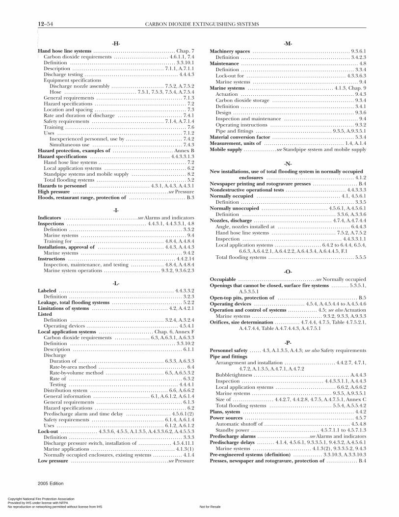
12–54 CARBON DIOXIDE EXTINGUISHING SYSTEMS
Copyright National FiProvided by IHS undeNo reproduction or ne
--`,,,```-`-`,,`,,`,`,,`---
-H-Hand hose line systems . . . . . . . . . . . . . . . . . . . . . . . . . . . . . . . . . . . . . . . . . . Chap. 7
Carbon dioxide requirements . . . . . . . . . . . . . . . . . . . . . . . . . . . . 4.6.1.1, 7.4Definition . . . . . . . . . . . . . . . . . . . . . . . . . . . . . . . . . . . . . . . . . . . . . . . . . . . . . . 3.3.10.1Description . . . . . . . . . . . . . . . . . . . . . . . . . . . . . . . . . . . . . . . . . . . . . . . 7.1.1, A.7.1.1Discharge testing . . . . . . . . . . . . . . . . . . . . . . . . . . . . . . . . . . . . . . . . . . . . . . . . 4.4.4.3Equipment specifications
Discharge nozzle assembly . . . . . . . . . . . . . . . . . . . . . . . . . . . 7.5.2, A.7.5.2Hose . . . . . . . . . . . . . . . . . . . . . . . . . . . . . . . . . . . . . 7.5.1, 7.5.3, 7.5.4, A.7.5.4
General requirements . . . . . . . . . . . . . . . . . . . . . . . . . . . . . . . . . . . . . . . . . . . . 7.1.3Hazard specifications . . . . . . . . . . . . . . . . . . . . . . . . . . . . . . . . . . . . . . . . . . . . . . . 7.2Location and spacing . . . . . . . . . . . . . . . . . . . . . . . . . . . . . . . . . . . . . . . . . . . . . . . 7.3Rate and duration of discharge . . . . . . . . . . . . . . . . . . . . . . . . . . . . . . . . . 7.4.1Safety requirements . . . . . . . . . . . . . . . . . . . . . . . . . . . . . . . . . . . . . 7.1.4, A.7.1.4Training . . . . . . . . . . . . . . . . . . . . . . . . . . . . . . . . . . . . . . . . . . . . . . . . . . . . . . . . . . . . . . 7.6Uses . . . . . . . . . . . . . . . . . . . . . . . . . . . . . . . . . . . . . . . . . . . . . . . . . . . . . . . . . . . . . . . . 7.1.2
Inexperienced personnel, use by . . . . . . . . . . . . . . . . . . . . . . . . . . . . . 7.4.2Simultaneous use . . . . . . . . . . . . . . . . . . . . . . . . . . . . . . . . . . . . . . . . . . . . . . 7.4.3
Hazard protection, examples of . . . . . . . . . . . . . . . . . . . . . . . . . . . . . . . Annex BHazard specifications . . . . . . . . . . . . . . . . . . . . . . . . . . . . . . . . . . . . . . . . . 4.4.3.3.1.3
Hand hose line systems . . . . . . . . . . . . . . . . . . . . . . . . . . . . . . . . . . . . . . . . . . . . . 7.2Local application systems . . . . . . . . . . . . . . . . . . . . . . . . . . . . . . . . . . . . . . . . . . 6.2Standpipe systems and mobile supply . . . . . . . . . . . . . . . . . . . . . . . . . . . . 8.2Total flooding systems . . . . . . . . . . . . . . . . . . . . . . . . . . . . . . . . . . . . . . . . . . . . . . 5.2
Hazards to personnel . . . . . . . . . . . . . . . . . . . . . . . . . . . . . . . 4.3.1, A.4.3, A.4.3.1High pressure . . . . . . . . . . . . . . . . . . . . . . . . . . . . . . . . . . . . . . . . . . . . . . . . .see PressureHoods, restaurant range, protection of . . . . . . . . . . . . . . . . . . . . . . . . . . . . . B.3
-I-Indicators . . . . . . . . . . . . . . . . . . . . . . . . . . . . . . . . . . . . . .see Alarms and indicatorsInspections . . . . . . . . . . . . . . . . . . . . . . . . . . . . . . . . . . . . . . . . . 4.4.3.1, 4.4.3.3.1, 4.8
Definition . . . . . . . . . . . . . . . . . . . . . . . . . . . . . . . . . . . . . . . . . . . . . . . . . . . . . . . . . . 3.3.2Marine systems . . . . . . . . . . . . . . . . . . . . . . . . . . . . . . . . . . . . . . . . . . . . . . . . . . . . . . 9.4Training for . . . . . . . . . . . . . . . . . . . . . . . . . . . . . . . . . . . . . . . . . . . . . . 4.8.4, A.4.8.4
Installations, approval of . . . . . . . . . . . . . . . . . . . . . . . . . . . . . . . . . . 4.4.3, A.4.4.3Marine systems . . . . . . . . . . . . . . . . . . . . . . . . . . . . . . . . . . . . . . . . . . . . . . . . . . . . 9.4.2
Instructions . . . . . . . . . . . . . . . . . . . . . . . . . . . . . . . . . . . . . . . . . . . . . . . . . . . . . . . 4.4.2.14Inspection, maintenance, and testing . . . . . . . . . . . . . . . . . 4.8.4, A.4.8.4Marine system operations . . . . . . . . . . . . . . . . . . . . . . . . . . . . . 9.3.2, 9.3.6.2.3
-L-Labeled . . . . . . . . . . . . . . . . . . . . . . . . . . . . . . . . . . . . . . . . . . . . . . . . . . . . . . . . . . . 4.4.3.3.2
Definition . . . . . . . . . . . . . . . . . . . . . . . . . . . . . . . . . . . . . . . . . . . . . . . . . . . . . . . . . . 3.2.3Leakage, total flooding systems . . . . . . . . . . . . . . . . . . . . . . . . . . . . . . . . . . . . 5.2.2Limitations of systems . . . . . . . . . . . . . . . . . . . . . . . . . . . . . . . . . . . . . . . 4.2, A.4.2.1Listed
Definition . . . . . . . . . . . . . . . . . . . . . . . . . . . . . . . . . . . . . . . . . . . . . . . . 3.2.4, A.3.2.4Operating devices . . . . . . . . . . . . . . . . . . . . . . . . . . . . . . . . . . . . . . . . . . . . . . . 4.5.4.1
Local application systems . . . . . . . . . . . . . . . . . . . . . . . . . . . . Chap. 6, Annex FCarbon dioxide requirements . . . . . . . . . . . . . . . . . . 6.3, A.6.3.1, A.6.3.3Definition . . . . . . . . . . . . . . . . . . . . . . . . . . . . . . . . . . . . . . . . . . . . . . . . . . . . . . 3.3.10.2Description . . . . . . . . . . . . . . . . . . . . . . . . . . . . . . . . . . . . . . . . . . . . . . . . . . . . . . . . 6.1.1Discharge
Duration of . . . . . . . . . . . . . . . . . . . . . . . . . . . . . . . . . . . . . . . . . . . . 6.3.3, A.6.3.3Rate-by-area method . . . . . . . . . . . . . . . . . . . . . . . . . . . . . . . . . . . . . . . . . . . . . 6.4Rate-by-volume method . . . . . . . . . . . . . . . . . . . . . . . . . . . . . . 6.5, A.6.5.3.2Rate of . . . . . . . . . . . . . . . . . . . . . . . . . . . . . . . . . . . . . . . . . . . . . . . . . . . . . . . . . . 6.3.2Testing . . . . . . . . . . . . . . . . . . . . . . . . . . . . . . . . . . . . . . . . . . . . . . . . . . . . . . . . 4.4.4.1
Distribution system . . . . . . . . . . . . . . . . . . . . . . . . . . . . . . . . . . . . . . . . 6.6, A.6.6.2General information . . . . . . . . . . . . . . . . . . . . . . . . . . . . . 6.1, A.6.1.2, A.6.1.4General requirements . . . . . . . . . . . . . . . . . . . . . . . . . . . . . . . . . . . . . . . . . . . . 6.1.3Hazard specifications . . . . . . . . . . . . . . . . . . . . . . . . . . . . . . . . . . . . . . . . . . . . . . . 6.2Predischarge alarm and time delay . . . . . . . . . . . . . . . . . . . . . . . 4.5.6.1(2)Safety requirements . . . . . . . . . . . . . . . . . . . . . . . . . . . . . . . . . . . . . 6.1.4, A.6.1.4Uses . . . . . . . . . . . . . . . . . . . . . . . . . . . . . . . . . . . . . . . . . . . . . . . . . . . . . . . 6.1.2, A.6.1.2
Lock-out . . . . . . . . . . . . . . . . . . . 4.3.3.6, 4.5.5, A.1.3.5, A.4.3.3.6.2, A.4.5.5.3Definition . . . . . . . . . . . . . . . . . . . . . . . . . . . . . . . . . . . . . . . . . . . . . . . . . . . . . . . . . . 3.3.3Discharge pressure switch, installation of . . . . . . . . . . . . . . . . . 4.5.4.11.1Marine applications . . . . . . . . . . . . . . . . . . . . . . . . . . . . . . . . . . . . . . . . . . . 4.1.3(1)Normally occupied enclosures, existing systems . . . . . . . . . . . . . . . 4.1.4
Low pressure . . . . . . . . . . . . . . . . . . . . . . . . . . . . . . . . . . . . . . . . . . . . . . . . . .see Pressure
2005 Edition
re Protection Association r license with NFPA
Not fortworking permitted without license from IHS
-M-Machinery spaces . . . . . . . . . . . . . . . . . . . . . . . . . . . . . . . . . . . . . . . . . . . . . . . . . . 9.3.6.1
Definition . . . . . . . . . . . . . . . . . . . . . . . . . . . . . . . . . . . . . . . . . . . . . . . . . . . . . . . . 3.4.2.3Maintenance . . . . . . . . . . . . . . . . . . . . . . . . . . . . . . . . . . . . . . . . . . . . . . . . . . . . . . . . . . . . 4.8
Definition . . . . . . . . . . . . . . . . . . . . . . . . . . . . . . . . . . . . . . . . . . . . . . . . . . . . . . . . . . 3.3.4Lock-out for . . . . . . . . . . . . . . . . . . . . . . . . . . . . . . . . . . . . . . . . . . . . . . . . . . . 4.3.3.6.3Marine systems . . . . . . . . . . . . . . . . . . . . . . . . . . . . . . . . . . . . . . . . . . . . . . . . . . . . . . 9.4
Marine systems . . . . . . . . . . . . . . . . . . . . . . . . . . . . . . . . . . . . . . . . . . . . 4.1.3, Chap. 9Actuation . . . . . . . . . . . . . . . . . . . . . . . . . . . . . . . . . . . . . . . . . . . . . . . . . . . . . . . . . . 9.4.3Carbon dioxide storage . . . . . . . . . . . . . . . . . . . . . . . . . . . . . . . . . . . . . . . . . . 9.3.4Definition . . . . . . . . . . . . . . . . . . . . . . . . . . . . . . . . . . . . . . . . . . . . . . . . . . . . . . . . . . 3.4.1Design . . . . . . . . . . . . . . . . . . . . . . . . . . . . . . . . . . . . . . . . . . . . . . . . . . . . . . . . . . . . . . 9.3.6Inspection and maintenance . . . . . . . . . . . . . . . . . . . . . . . . . . . . . . . . . . . . . . 9.4Operating instructions . . . . . . . . . . . . . . . . . . . . . . . . . . . . . . . . . . . . . . . . . . . 9.3.2Pipe and fittings . . . . . . . . . . . . . . . . . . . . . . . . . . . . . . . . . . . . . . . 9.3.5, A.9.3.5.1
Material conversion factor . . . . . . . . . . . . . . . . . . . . . . . . . . . . . . . . . . . . . . . . . . 5.3.4Measurement, units of . . . . . . . . . . . . . . . . . . . . . . . . . . . . . . . . . . . . . . . . . 1.4, A.1.4Mobile supply . . . . . . . . . . . . . . . . .see Standpipe system and mobile supply
-N-New installations, use of total flooding system in normally occupied
enclosures . . . . . . . . . . . . . . . . . . . . . . . . . . . . . . . . . . . . . . . . . . . . . 4.1.2Newspaper printing and rotogravure presses . . . . . . . . . . . . . . . . . . . . . . . B.4Nondestructive operational tests . . . . . . . . . . . . . . . . . . . . . . . . . . . . . . . 4.4.3.3.3Normally occupied . . . . . . . . . . . . . . . . . . . . . . . . . . . . . . . . . . . . . . . . . . . 4.1, 4.5.6.1
Definition . . . . . . . . . . . . . . . . . . . . . . . . . . . . . . . . . . . . . . . . . . . . . . . . . . . . . . . . . . 3.3.5Normally unoccupied . . . . . . . . . . . . . . . . . . . . . . . . . . . . . . . . . . 4.5.6.1, A.4.5.6.1
Definition . . . . . . . . . . . . . . . . . . . . . . . . . . . . . . . . . . . . . . . . . . . . . . . . 3.3.6, A.3.3.6Nozzles, discharge . . . . . . . . . . . . . . . . . . . . . . . . . . . . . . . . . . . . . . . . 4.7.4, A.4.7.4.4
Angle, nozzles installed at . . . . . . . . . . . . . . . . . . . . . . . . . . . . . . . . . . . . . 6.4.4.3Hand hose line systems . . . . . . . . . . . . . . . . . . . . . . . . . . . . . . . . . 7.5.2, A.7.5.2Inspection . . . . . . . . . . . . . . . . . . . . . . . . . . . . . . . . . . . . . . . . . . . . . . . . . . . 4.4.3.3.1.1Local application systems . . . . . . . . . . . . . . . . . . . . . . . . 6.4.2 to 6.4.4, 6.5.4,
6.6.3, A.6.4.2.1, A.6.4.2.2, A.6.4.3.4, A.6.4.4.5, F.1Total flooding systems . . . . . . . . . . . . . . . . . . . . . . . . . . . . . . . . . . . . . . . . . . . . 5.5.5
-O-Occupiable . . . . . . . . . . . . . . . . . . . . . . . . . . . . . . . . . . . . . . . .see Normally occupiedOpenings that cannot be closed, surface fire systems . . . . . . . . . 5.3.5.1,
A.5.3.5.1Open-top pits, protection of . . . . . . . . . . . . . . . . . . . . . . . . . . . . . . . . . . . . . . . . . B.5Operating devices . . . . . . . . . . . . . . . . . . . . . . . . . . 4.5.4, A.4.5.4.4 to A.4.5.4.6Operation and control of systems . . . . . . . . . . . . . . . 4.5; see also Actuation
Marine systems . . . . . . . . . . . . . . . . . . . . . . . . . . . . . . . . . . . . 9.3.2, 9.3.3, A.9.3.3Orifices, size determination . . . . . . . . . . . . . 4.7.4.4, 4.7.5, Table 4.7.5.2.1,
A.4.7.4.4, Table A.4.7.4.4.3, A.4.7.5.1
-P-Personnel safety . . . . . . 4.3, A.1.3.5, A.4.3; see also Safety requirementsPipe and fittings
Arrangement and installation . . . . . . . . . . . . . . . . . . . . . . . . . . 4.4.2.7, 4.7.1,4.7.2, A.1.3.5, A.4.7.1, A.4.7.2
Bubbletightness . . . . . . . . . . . . . . . . . . . . . . . . . . . . . . . . . . . . . . . . . . . . . . . . . A.4.4.3Inspection . . . . . . . . . . . . . . . . . . . . . . . . . . . . . . . . . . . . . . . . . . 4.4.3.3.1.1, A.4.4.3Local application systems . . . . . . . . . . . . . . . . . . . . . . . . . . . . . . . 6.6.2, A.6.6.2Marine systems . . . . . . . . . . . . . . . . . . . . . . . . . . . . . . . . . . . . . . . . . 9.3.5, A.9.3.5.1Size of . . . . . . . . . . . . . . . . . . . . . 4.4.2.7, 4.4.2.8, 4.7.5, A.4.7.5.1, Annex CTotal flooding systems . . . . . . . . . . . . . . . . . . . . . . . . . . . . . . . . 5.5.4, A.5.5.4.2
Plans, system . . . . . . . . . . . . . . . . . . . . . . . . . . . . . . . . . . . . . . . . . . . . . . . . . . . . . . . . . 4.4.2Power sources . . . . . . . . . . . . . . . . . . . . . . . . . . . . . . . . . . . . . . . . . . . . . . . . . . . . . . . . 4.5.7
Automatic shutoff of . . . . . . . . . . . . . . . . . . . . . . . . . . . . . . . . . . . . . . . . . . . . 4.5.4.8Standby power . . . . . . . . . . . . . . . . . . . . . . . . . . . . . . . . . . . 4.5.7.1.1 to 4.5.7.1.3
Predischarge alarms . . . . . . . . . . . . . . . . . . . . . . . . . . .see Alarms and indicatorsPredischarge delays . . . . . . . . . 4.1.4, 4.5.6.1, 9.3.3.5.1, 9.4.3.2, A.4.5.6.1
Marine systems . . . . . . . . . . . . . . . . . . . . . . . . . . . . . . 4.1.3(2), 9.3.3.5.2, 9.4.3Pre-engineered systems (definition) . . . . . . . . . . . . . . . 3.3.10.3, A.3.3.10.3
Presses, newspaper and rotogravure, protection of . . . . . . . . . . . . . . . . B.4Resale

12–55INDEX
Copyright National Fire PrProvided by IHS under liceNo reproduction or networ
PressureHigh
Cylinders . . . . . . . . . . . . . . . . . . . . . . . . . . . . . . . . . . . . . . . . . . . . . . . .see CylindersDefinition . . . . . . . . . . . . . . . . . . . . . . . . . . . . . . . . . . . . . . . . . 3.3.8.1, A.3.3.8.1Distribution systems . . . . . . . . . . . . . . . . . . . . . . .see Distribution systems
LowDefinition . . . . . . . . . . . . . . . . . . . . . . . . . . . . . . . . . . . . . . . . . 3.3.8.2, A.3.3.8.2Distribution systems . . . . . . . . . . . . . . . . . . . . . . .see Distribution systemsStorage containers, low-pressure . . . . . . . . . . . 4.6.6, 9.3.4.2, A.4.6.6
Purpose of standard . . . . . . . . . . . . . . . . . . . . . . . . . . . . . . . . . . . . . . . . . . . . . . . . . . . 1.2
-R-References . . . . . . . . . . . . . . . . . . . . . . . . . . . . . . . . . . . . . . . . . . . . Chap. 2, Annex HRescue . . . . . . . . . . . . . . . . . . . . . . . . . . . . . . . . . . . . . . . . . . . . . . . . . . . . . 4.3.1.3.1, A.4.3Retroactivity of standard . . . . . . . . . . . . . . . . . . . . . . . . . . . . . . . . . . . . . 1.3, A.1.3.5Rotogravure presses . . . . . . . . . . . . . . . . . . . . . . . . . . . . . . . . . . . . . . . . . . . . . . . . . . . B.4
-S-Safety requirements . . . . . . . . . . . . . . . . . . A.1.3.5; see also Personnel safety
Hand hose line systems . . . . . . . . . . . . . . . . . . . . . . . . . . . . . . . . . 7.1.4, A.7.1.4Local application systems . . . . . . . . . . . . . . . . . . . . . . . . . . . . . . . 6.1.4, A.6.1.4
Scope of standard . . . . . . . . . . . . . . . . . . . . . . . . . . . . . . . . . . . . . . . . . . . . . . 1.1, A.1.1Self-contained breathing apparatus (SCBA) . . . . . . . 4.3.3.1.1, A.4.3.1.3Shall (definition) . . . . . . . . . . . . . . . . . . . . . . . . . . . . . . . . . . . . . . . . . . . . . . . . . . . . . 3.2.5Should (definition) . . . . . . . . . . . . . . . . . . . . . . . . . . . . . . . . . . . . . . . . . . . . . . . . . . 3.2.6Signs, warning . . . . . . . . . . . . . . . . . . . . . . . . . . . . . . . . . . . . . . . 4.3.2, A.1.3.5, A.4.3Spaces
Cargo . . . . . . . . . . . . . . . . . . . . . . . . . . . . . . . . . . . . . . . . . . . . . . . . . . . . . . . . . . . . . 9.3.6.2Definition . . . . . . . . . . . . . . . . . . . . . . . . . . . . . . . . . . . . . . . . . . . . . . . . . . . . . 3.4.2.1
Electrical equipment . . . . . . . . . . . . . . . . . . . . . . . . . . . . . . . . . . . . . . . . . . . . . 9.3.7Definition . . . . . . . . . . . . . . . . . . . . . . . . . . . . . . . . . . . . . . . . . . . . . . . . . . . . . 3.4.2.2
Machinery . . . . . . . . . . . . . . . . . . . . . . . . . . . . . . . . . . . . . . . . . . . . . . . . . . . . . . . 9.3.6.1Definition . . . . . . . . . . . . . . . . . . . . . . . . . . . . . . . . . . . . . . . . . . . . . . . . . . . . . 3.4.2.3
Vehicle . . . . . . . . . . . . . . . . . . . . . . . . . . . . . . . . . . . . . . . . . . . . . . . . . . 9.3.6.3, 9.3.6.4Definition . . . . . . . . . . . . . . . . . . . . . . . . . . . . . . . . . . . . . . . . . . . . . . . . . . . . . 3.4.2.4
Special conditionsDeep-seated fires, systems for . . . . . . . . . . . . . . . . . . . . . . . . . . . . . . . . . . . . 5.4.4Surface fires, systems for . . . . . . . . . . . . . . . . . . . . . . . . . . . . . . . . 5.3.5, A.5.3.5
SpecificationsHazard . . . . . . . . . . . . . . . . . . . . . . . . . . . . . . . . . . . . . . .see Hazard specificationsSystem . . . . . . . . . . . . . . . . . . . . . . . . . . . . . . . . . . . . . . . . . . . . . . . . . . . . . . . . . . . . . . 4.4.1
Standard (definition) . . . . . . . . . . . . . . . . . . . . . . . . . . . . . . . . . . . . . . . . . . . . . . . . 3.2.7Standby power . . . . . . . . . . . . . . . . . . . . . . . . . . . . . . . . . . . . . . 4.5.7.1.1 to 4.5.7.1.3Standpipe system and mobile supply . . . . . . . . . . . . . . . . . . . . . . . . . . . Chap. 8
Definition . . . . . . . . . . . . . . . . . . . . . . . . . . . . . . . . . . . . . . . . . . . . . . . . . . . . . . . . . . 3.3.9Description . . . . . . . . . . . . . . . . . . . . . . . . . . . . . . . . . . . . . . . . . . . . . . . 8.1.1, A.8.1.1General requirements . . . . . . . . . . . . . . . . . . . . . . . . . . . . . . . . . . . . . . . . . . . . 8.1.3Hazard specifications . . . . . . . . . . . . . . . . . . . . . . . . . . . . . . . . . . . . . . . . . . . . . . . 8.2Mobile supply requirements . . . . . . . . . . . . . . . . . . . . . . . . . . . . . . 8.4, A.8.4.1
Accessories . . . . . . . . . . . . . . . . . . . . . . . . . . . . . . . . . . . . . . . . . . . . . . . . . . . . . . 8.4.5Capacity . . . . . . . . . . . . . . . . . . . . . . . . . . . . . . . . . . . . . . . . . . . . . . . . 8.4.1, A.8.4.1Coupling . . . . . . . . . . . . . . . . . . . . . . . . . . . . . . . . . . . . . . . . . . . . . . . . . . . . . . . . 8.4.2Location . . . . . . . . . . . . . . . . . . . . . . . . . . . . . . . . . . . . . . . . . . . . . . . . . . . . . . . . 8.4.4Mobility . . . . . . . . . . . . . . . . . . . . . . . . . . . . . . . . . . . . . . . . . . . . . . . . . . . . . . . . . 8.4.3Training . . . . . . . . . . . . . . . . . . . . . . . . . . . . . . . . . . . . . . . . . . . . . . . . . . . 8.5, A.8.5
Standpipe requirements . . . . . . . . . . . . . . . . . . . . . . . . . . . . . . . . . . . . . . . . . . . . 8.3Training . . . . . . . . . . . . . . . . . . . . . . . . . . . . . . . . . . . . . . . . . . . . . . . . . . . . . . 8.5, A.8.5Uses . . . . . . . . . . . . . . . . . . . . . . . . . . . . . . . . . . . . . . . . . . . . . . . . . . . . . . . 8.1.2, A.8.1.2
Stop valves, systems with . . . . . . . . . . . . . . . . . . . . . . . . . . . . . . . . . . . . . . 9.4.2.2.1.1Storage
High-pressure storage, systems using . . . . . . .see Distribution systemsHose line . . . . . . . . . . . . . . . . . . . . . . . . . . . . . . . . . . . . . . . . . . . . . . . . . . . . . . . . . . . 7.5.3
Cou/D 1 2 3 4 5 6 09 08 07 06 05
otection Association nse with NFPA
Not for Resaking permitted without license from IHS
--`,,,```-`-`,,`,,`,`,,`---
Storage containers . . . . . . . . . . . . . . . . . . . . . . . . . . . . . . 4.6.4; see also CylindersLow-pressure . . . . . . . . . . . . . . . . . . . . . . . . . . . . . . . . . . . . 4.6.6, 9.3.4.2, A.4.6.6
Maintenance and tests . . . . . . . . . . . . . . . . . . . . . . . . . . . . . . . . . . . . . . 4.8.3.5Marine systems . . . . . . . . . . . . . . . . . . . . . . . . . . . . . . . . . . . . . . . . . . . . . . . . . . . . 9.3.4Nameplate data . . . . . . . . . . . . . . . . . . . . . . . . . . . . . . . . . . . . . . . . . . . . . 4.4.3.3.2.2
Supervision of systems . . . . . . . . . . . . . . . . . . . . . . . . . . . . . . . . . . . 4.5.5, A.4.5.5.3Surface fires . . . . . . . . . . . . 5.2.1.1, 5.2.3, 5.3, A.5.2.1.1, A.5.2.3, Annex ESystem specifications . . . . . . . . . . . . . 4.4.1; see also Hazard specificationsSystems . . . . . . . . . . . . . . . . . . . . . . . . . . . . . . . . . . . . . . . see particular types of systems
-T-Testing of systems . . . . . . . . . . . . . . . . . . . . . . . . . . 4.8.3, 4.8.4, A.4.8.3, A.4.8.4
Approval . . . . . . . . . . . . . . . . . . . . . . . . . . . . . . . . . . . . . . . . . . . . . . . . . . . . . . . . . 4.4.3.1Full discharge . . . . . . . . . . . . . . . . . . . . . . 4.4.3.3.4, 4.4.4, 4.5.4.6.3, A.4.4.3Hose . . . . . . . . . . . . . . . . . . . . . . . . . . . . . . . . . . . . . . . . . . . . . . . . . . . . . . . . . . . . . . . . 4.8.2Lock-out for . . . . . . . . . . . . . . . . . . . . . . . . . . . . . . . . . . . . . . . . . . . . . . . . . . . 4.3.3.6.3Operational tests . . . . . . . . . . . . . . . . . . . . . . . . . . . . . . . . . . . . . . . . . . . . . . 4.4.3.3.3
Time delays . . . . . . . . . . . . . . . . . . . . . . . . . . . . . . . . . . . . . . .see Predischarge delaysTotal flooding systems . . . . . . . . . . . . . . . . . . . . . . . . . . . . . . . . . . . . . . . . . . . Chap. 5
Carbon dioxide requirementsFor deep-seated fires . . . . . 5.2.1.3, 5.4, A.5.2.1.3, A.5.4.1, A.5.4.2For surface fires . . . . . . . . . . . . . . . . . . . . . . . . . . . . . 5.2.1.1, 5.3, A.5.2.1.1
Definition . . . . . . . . . . . . . . . . . . . . . . . . . . . . . . . . . . . . . . . . . . . . . . . . . . . . . . 3.3.10.4Description . . . . . . . . . . . . . . . . . . . . . . . . . . . . . . . . . . . . . . . . . . . . . . . . . . . . . . . . 5.1.1Discharge testing . . . . . . . . . . . . . . . . . . . . . . . . . . . . . . . . . . . . . . . . . . . . . . . . 4.4.4.2Distribution system . . . . . . . . . . . . . . . . . . . . . . . . . . . . . . . . . . . . . . . . . . . . . . . . . 5.5Fires, types of . . . . . . . . . . . . . . . . . . . . . . . . . . . . . . . . . . . . . . . . . . . . 5.2.3, A.5.2.3Flooding factor . . . . . . . . . . . . . . . . . . . . . . . . . . . . . . . . . . . . . . 5.3.5.7, A.5.3.5.7General information . . . . . . . . . . . . . . . . . . . . . . . . . . . 5.1, A.5.1.2, Annex DGeneral requirements . . . . . . . . . . . . . . . . . . . . . . . . . . . . . . . . . . . . . . . . . . . . 5.1.3Hazard specifications . . . . . . . . . . . . . . . . . . . . . . . . . . . . . . . . . . . . . . . . . . . . . . . 5.2High-pressure cylinders, storage temperatures for . . . . . . . . 4.6.5.5.1Marine applications, manually operated . . . . . . . . . . . . . . . . . . . . . . . 4.1.3Material conversion factor . . . . . . . . . . . . . . . . . . . . . . . . . . . . . . . . . . . . . . . 5.3.4Normally occupied enclosures, use in . . . . . . . . . . . . . . . . . 4.1, A.4.1.1.1Predischarge alarm and time delay . . . . . . . . . . . . . . . . . . . . . . . 4.5.6.1(1)Uses . . . . . . . . . . . . . . . . . . . . . . . . . . . . . . . . . . . . . . . . . . . . . . . . . . . . . . . 5.1.2, A.5.1.2Venting . . . . . . . . . . . . . . . . . . . . . . . . . . . . . . . 5.6, A.4.3.3.1.1, A.5.6.1, A.5.6.2
TrainingExisting warning signs . . . . . . . . . . . . . . . . . . . . . . . . . . . . . . . . . . . . . . . . . . 4.3.2.4Hand hose lines . . . . . . . . . . . . . . . . . . . . . . . . . . . . . . . . . . . . . . . . . . . . . . . . . . . . . 7.6Safety . . . . . . . . . . . . . . . . . . . . . . . . . . . . . . . . . . . . . . . . . . . . . . . . . . . 4.3.1.3.2, A.4.3Standpipe systems and mobile supply . . . . . . . . . . . . . . . . . . . . . 8.5, A.8.5
-U-Units of measurement . . . . . . . . . . . . . . . . . . . . . . . . . . . . . . . . . . . . . . . . . . . . . . . . . 1.4Unoccupiable (definition) . . . . . . . . . . . . . . . . . . . . . . . . . . . . . . . . . . . . . . . . . 3.3.11Uses of systems . . . . . . . . . . . . . . . . . . . . . . . . . . . . . . . . . . . . . . . . . . . . . . . 4.2, A.4.2.1
-V-Valves . . . . . . . . . . . . . . . . . . . . . . . . . . . . . . . . . . . . . . . . . . . . . . . . . . . . . . . . . . . . . . . . . . 4.7.3Vehicle spaces . . . . . . . . . . . . . . . . . . . . . . . . . . . . . . . . . . . . . . . . . . . . . 9.3.6.3, 9.3.6.4
Definition . . . . . . . . . . . . . . . . . . . . . . . . . . . . . . . . . . . . . . . . . . . . . . . . . . . . . . . . 3.4.2.4Ventilation . . . . . . . . . . . . . . . . . . . . . . . . . . . . . . . . . . . . . . . . . . . . . . . . . . . . . . . . . . . . A.4.3
Shutdowns, marine systems . . . . . . . . . . . . . . . . . . . . . . . . . . . . . . . . . . . . 9.4.3.1Surface fires, systems for . . . . . . . . . . . . . . . . . . . . . . . . . . . . . . . . . . . . . . . 5.3.5.2Total flooding systems . . . . . . . . . . . . . . . . . . . . . . . . . . . . . . 5.2.2, A.4.3.3.1.1
VentingPressure relief . . . . . . . . . . . . . . . . . . . . . . . . . . . . . . . . . . . . . . . . . . . . 5.6.2, A.5.6.2Total flooding systems . . . . . . . . . . . . . . . . . . . . . . . . . . . 5.6, A.5.6.1, A.5.6.2
Volume factor . . . . . . . . . . . . . . . . . . . . . . . . . . . . . . . . . . . . . . 5.3.3, 5.4.3, A.5.3.3.1
Low-pressure storage, systems using . . . . . . . .see Distribution systems Interconnected volumes . . . . . . . . . . . . . . . . . . . . . . . . . . . . . . . . . . . . . . . 5.3.3.22005 Edition
le

Copyright National Fire Protection Association Provided by IHS under license with NFPA
Not for ResaleNo reproduction or networking permitted without license from IHS
--`,,,```-`-`,,`,,`,`,,`---

Copyright National Fire Protection Association Provided by IHS under license with NFPA
Not for ResaleNo reproduction or networking permitted without license from IHS
--`,,,```-`-`,,`,,`,`,,`---

Copyright National Fire Protection Association Provided by IHS under license with NFPA
Not for ResaleNo reproduction or networking permitted without license from IHS
--`,,,```-`-`,,`,,`,`,,`---