Embed Size (px)
Citation preview

Technical Committee on Fire Hose
(FHS-AAA) NFPA 1961 Second Draft Meeting (Annual 2017)
Wednesday, May 25th, 2016 – May 26th 2016
Double Tree by Hilton
Denver, CO 80207-2319
AGENDA
1. Call to Order – At conclusion of the Research Foundation Workshop
2. Introduction and Attendance
3. Review Agenda
4. NFPA Staff Liaison Presentation and Review of Key Dates in A2017 Cycle
5. Chairman Comments
6. Approval of Previous Meeting Minutes
7. Act on remaining Public Comments for NFPA 1962 & 1964
8. New business related to NFPA 1962 & 1964
9. Generate Committee Comments for NFPA 1961
a. Discuss research and data gathered at workshop and how to incorporate
into NFPA 1961 & 1962.
10. Act on Public Comments for NFPA 1961
11. Other Business
12. Next Meeting
13. Adjourn Meeting – Evening of Thursday, May 26th 2016
Please submit requests for additional agenda items to the chair and staff liaison at least seven days prior to the meeting.
Page 1 of 63
Technical Committee on Fire Hose
(FHS-AAA) NFPA 1961 Second Draft Meeting (Annual 2017)
Wednesday, May 25th – Thursday, May 26th
Denver, CO
Key Dates for the Annual 2017 Revision Cycle
Final Date for First Draft Meeting December 14, 2015
Posting of First Draft and TC Ballot February 1, 2016
Final date for Ballot Return February 22, 2016
Post First Draft Report for Public Comment March 7, 2016
Public Comment Closing Date May 16, 2016
Final Date for Second Draft Meeting October 31, 2016
Posting of Second Draft and TC Ballot December 12, 2016
Final Date for Ballot Return January 2, 2017
Final Second Draft Posted January 16, 2017
Closing Date for Notice of Intent to Make a Motion (NITMAM) February 20, 2017
Issuance of Consent Document (No NITMAMs) May 12, 2017
NFPA Annual Meeting June 2017
Issuance of Document with NITMAM August 10, 2017
Technical Committee deadlines are in bold.
Page 2 of 63

05/11/2016
Fire HoseFHS-AAAName Representation Class Office
Distribution by %
Company
Christopher B. Budzinski City of Asheville Fire Department E Principal
Brian Fink Fire Department City of New York FDNY E Principal
Jayme L. Kahle Rincon Valley Fire District E Principal
Brian P. Kazmierzak Penn Township Fire Department E Principal
Paul Prevost Clearwater Regional Fire RescueService
E Principal
John W. Stacey IAFC E Principal
David Walsh Boston Fire Department E Principal
7Voting Number Percent 24%
Thomas G. Farruggia Illinois Fire & Safety Company NAFED IM Principal
James E. Glatts FireOne IM Principal
Edward J. O’Kinsky Waterway Inc. IM Principal
Marc T. Radecky FireCatt LLC IM Principal
4Voting Number Percent 14%
Michael S. Aubuchon, Sr. North American Fire Hose Corporation M Principal
Gregory Kozey Kochek Company, Inc. M Principal
Duane Leonhardt Mercedes Textiles Ltd. FEMA M Principal
Toby Mathews Key Fire Hose Corporation M Principal
Michael Mayer Task Force Tips M Principal
Jason D. Riggenbach Akron Brass Company M Principal
Robert Dunn All-American Hose, LLC M Voting Alternate
7Voting Number Percent 24%
Jeff Hebenstreit UL LLC UL RT Principal
Samuel Wu US Department of Agriculture RT Principal
2Voting Number Percent 7%
Andrew D. Ellison Exponent, Inc. SE Chair
William T. Graves William Graves Associates LLC SE Principal
Page 3 of 63

Wednesday 5 11, Wednesday
Fire HoseFHS-AAAName Representation Class Office
Distribution by %
Company
David J. Pritchard Pritchard & Associates (NC), Inc. SE Principal
3Voting Number Percent 10%
Jason Goodale Loveland Fire Rescue U Secretary
Bill C. Betz Fairfax County Fire & RescueDepartment
U Principal
Jonathan R. Cares Town of Londonderry Fire Rescue U Principal
David Quick Manchester Fire Department U Principal
Tim Vanderlip Los Angeles County Fire Department U Principal
Paul R. Kaveler Ameren Services EEI U Voting Alternate
6Voting Number Percent 21%
29Total Voting Number
Page 4 of 63

Technical Committee on Fire Hose (FHS-AAA)
NFPA 1961 Second Draft Meeting (Annual 2017) May 25 - 26, 2016
General Procedures for Meetings
Use of tape recorders or other means capable of producing verbatim transcriptions of any NFPA Committee Meeting is not permitted.
Attendance at all NFPA Committee Meetings is open. All guests must sign in and identify their affiliation.
Participation in NFPA Committee Meetings is generally limited to committee members and NFPA staff. Participation by guests is limited to individuals, who have received prior approval from the chair to address the committee on a particular item, or who wish to speak regarding public proposals or comments that they submitted.
The chairman reserves the right to limit the amount of time available for any presentation.
No interviews will be allowed in the meeting room at any time, including breaks.
All attendees are reminded that formal votes of committee members will be secured by letter ballot. Voting at this meeting is used to establish a sense of agreement, but only the results of the formal letter ballot will determine the official action of the committee.
Note to Special Experts: Particular attention is called to Section 3.3(e ) of the NFPA Guide for Conduct of Participants in the NFPA Codes and Standards Development Process in the NFPA Directory. This section requires committee members to declare any interest they may represent, other than their official designation as shown on the committee roster. This typically occurs when a special expert is trained by and represents another interest category on a particular subject. If such a situation exists on a specific issue or issues, the committee member shall declare those interest to the committee and refrain from voting on any action relating to those issues.
Smoking is not permitted at NFPA Committee Meetings.
Page 5 of 63

Minutes from the
Previous Meeting
Page 6 of 63

Revised: 15-November-2015
Page 7 of 63
Page 8 of 63

Page 9 of 63
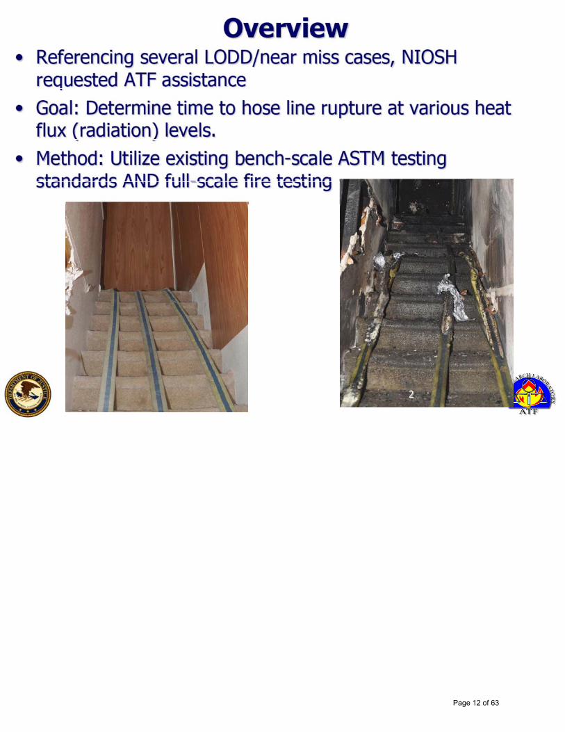
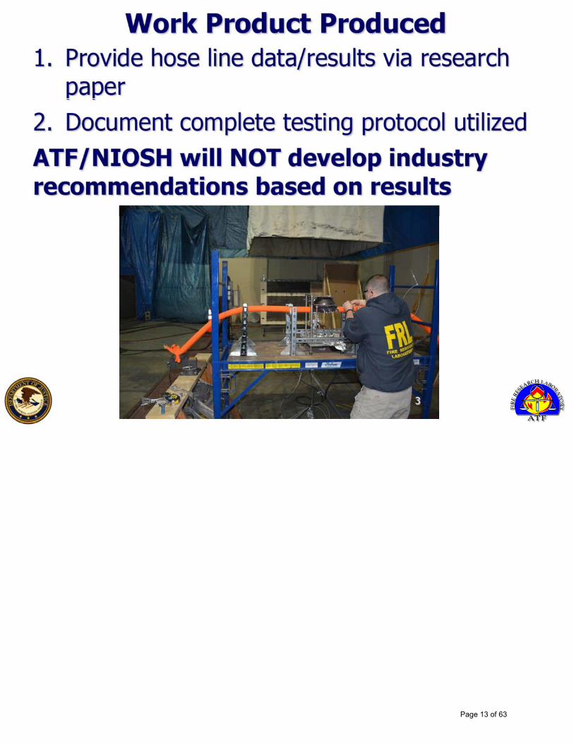
ATTACHMENT A Thermal Impact of Radiant Heat on
Interior Fire Attack Hose
Page 10 of 63

Thermal Impact of Radiant Heat on Interior Fire Attack Hose
ATF Fire Research Laboratoryand
National Institute for Occupational Safety and Health
Page 11 of 63
Page 12 of 63
Page 13 of 63

Page 14 of 63

Page 15 of 63

Page 16 of 63

W/m^2
Page 17 of 63

Page 18 of 63

Page 19 of 63

Page 20 of 63

Page 21 of 63

ATTACHMENT B Next Generation Fire Attack Hose
Page 22 of 63

10/18/2015
1
Page 23 of 63

10/18/2015
2
Page 24 of 63

10/18/2015
3
Page 25 of 63

10/18/2015
4
Page 26 of 63

10/18/2015
5
Page 27 of 63

10/18/2015
6
Page 28 of 63
10/18/2015
7
Page 29 of 63
10/18/2015
8
Page 30 of 63

10/18/2015
9
Page 31 of 63

10/18/2015
10
Page 32 of 63
10/18/2015
11
Page 33 of 63

10/18/2015
12
Page 34 of 63

10/18/2015
13
Page 35 of 63
10/18/2015
14
Page 36 of 63

10/18/2015
15
Page 37 of 63

10/18/2015
16
Page 38 of 63

10/18/2015
17
Page 39 of 63

10/18/2015
18
Page 40 of 63

10/18/2015
19
Page 41 of 63
ATTACHMENT C Proposed revisions provided by Kathy
Crosby-Bell
Page 42 of 63

Section NFPA 1961, Chapter 3, New Section Revise text to read as follows:
3.3.X Single Jacketed Lightweight Hose. Hose intended for use only in buildings higher than 6-stories.
Substantiation Provides a definition of lightweight hose in conjunction with a proposal to add it to the mandatory requirements of the document. Lightweight hose is designed to reduce the physical burden on fire fighter when being carried in high-rise buildings. This hose construction does not offer the same level of protection as double-jacketed hose. Should not be used in buildings under 6-stories. The premise of 6-stories is a reasonable amount expected for a firefighter to carry something heavy.
Section NFPA 1961, Chapter 5, New Section Revise text to read as follows:
5.6.2 All Single Jacketed Lightweight hose shall be marked with the wor�s “Single Jacketed Lightweig�� �ose”.
Substantiation Single Jacketed Lightweight fire hose needs to be clearly marked as such. Single Jacketed Lightweight hose is defined as hose intended for use in buildings higher than 6-stories. Single Jacketed-Lightweight hose shall not be considered compliant for any other applications.
Section NFPA 1961, Chapter 5, 5.5.1 Revise text to read as follows:
5.5.1(6) Ability to pass thermal test of PPE footwear in NFPA 1971 including:
a) Conductive Heat Resistance Test 2 (1971-2013, Section 8.8) b) Flame resistance test 4 (1971-2013, Section 8.5) - replacing
references to boot and then conduct hydrostatic pressure test c) Radiant Heat Resistance Test 1 (1971-2013, Section 8.9) d) Thread Melting Test (1971-2013, Section 8.11)
Tested charged and uncharged. Hydrostatic test following thermal assault Every hose failure shall be documented and reported to NFPA and Manufacturer e) NFPA format shall be provided for this purpose
Substantiation Firehose is exposed to the same operational environment and thermal assault conditions as firefighter personnel protective footwear. Test standards exist for thermal assault of firefighter footwear. These same standards can reasonably be modified and applied to fire hose
Page 43 of 63

compliance testing. By raising the compliant standard of 1961, existing technologies and innovation and emerging science will finally be applied to fire hose. FOR INVESTIGATION BY QUALIFIED INTERESTED STAKEHOLDERS Materials that may be used for new fire hose. NASA is Working with the US Forestry Service to develop improved fire shelter. I’ve spoken with a NASA engineer who is willing to participate in a conference call with stakeholders to discuss the possibility of the materials currently being modified for fireproof fire shelters being useful or modified for fire hose application. He is open to conference call with interested research and development personnel. I found what is reported to be flameproof fire attack hose online. This is being produced by a company I am told is reputable – no guarantees. I am attempting to have pertinent specifications, documents, testing criteria, standards, and pricing translated. Flame proof hose: currently being manufactured in Japan Please see print out provided. http:/ /www.ashimori.co.jp/english/product/bosai/hose/bh-attack/ index.html
Page 44 of 63
ATTACHMENT D Full-scale Exposure Testing of Hoselines
Page 45 of 63

To: NFPA 1961 Technical Committee
From: Daniel Madrzykowskis:Craig Weinschenks:NIST Firefighting Technology Group
Subject: Full-scale Exposure Testing of Hoselines
Date: October 12, 2015
This letter report documents two experimentsperformed at therequest of NFPA staff for usebythe NFPA Technical Committee on Fire Hose. The objective of the experiments was to gain someinsight into the failure of fi re hose as a result of thermal insult. Three different hose conditionswere examined; hose fi l led with air, hose fi l led with water, hose flowing 568 lpm (150 gpm) ofwater.
1 Experimental Test Arrangement
The experiments were conducted in a two story structure that was built to simulate a townhousewith a walk out basement. The structure was built on a concrete slab. The lower level of the struc-ture had an outer wall composed of 0.6 m (2 ft) thick interlocking concrete blocks. The joints andgaps between the blocks were fi l led with high temperature foam insulation. The interior walls ofthe lower level were framed with steel studs and track. The studs were set to 0.40 m (16 in.) cen-ters. The ceiling/ floor support was composed of wood truss joist I-beams (TJIs) with a 299 mm(11.75 in.) depth. Each TJI was composed of laminated veneer lumber flanges with a cross sectionof 29 mm (1.13 in.) x 44 mm (1.75 in.) and an 11 mm (0.43 in.) thick oriented strand board web.Tongue and grove, 18.3 mm (0.72 in.) thick, oriented strand board was screwed to the top of theTJIs to form the floor of the upper level. The walls and ceiling of the lower level was composed oftwo layers of 12.7 mm (0.5 in.) thick cement board.
The upper level of the structure was built on the wood floor assembly above. The walls wereframed with wood studs set to 0.40 m (16 in.) centers. The walls and ceiling of the upper levelwere composed of two layers of 12.7 mm (0.5 in.) thick cement board.
The interior footprint of the lower level is approximately 5.7 m (18.7 ft) wide by 10.6 m (34.8 ft)deep. The interior area of theupper level isapproximately 6.0 m (19.8 ft) wideby 11 m (36 ft) deep.Figures 1 and 2 are schematics of the floor plans of the upper and lower levels. In these images,circles indicate the location of thermocouples, squares indicate the location of velocity probes andthermocouples, diamonds indicate gas measurement probes, and triangles indicate the location ofheat flux measurements.
On Side C of the lower level, there is a set of doors with a total opening of approximately 1.8 m(6 ft) w ide and 2.0 m (6.7 ft) high. These doors were open for the duration of the hose exposureexperiments.
1
Page 46 of 63

C"Side"
A"S
ide"
Couc
h"1"
Couc
h"2"
Couc
h"3"
Figure 1: Schematic of Lower Level
C"Side"A"S
ide"
Top"of"Stairwell"
Figure 2: Schematic of Upper Level
On Side A of the lower level the single door remained closed for these experiments. The doorwas undercut to allow the hoses to pass through without any obstruction. Non-combustible fiberwas then packed around the hoses to minimize any leakage under the door. An open stair extendsfrom Side A and leads to the upper level with an open doorway facing Side C of the structure.The ventilation openings on the upper level include a 0.91 m (3 ft) by 2.0 m (6.7 ft) doorway and a1.7 m (5.5 ft) wide by 0.91 m (3 ft) high window with a 1.1 m (3.6 ft) sill height on the A side. On Csideof the upper level is another set of doubledoors similar in size to theset of doors on the lowerlevel. A ll of the openings on theupper level remained closed for the duration of thehose exposureexperiments. See schematics of the floor plans (Fig. 1 and 2) of both levels and photographs of theexterior of the structure (cf. Fig. 3).
2
Page 47 of 63
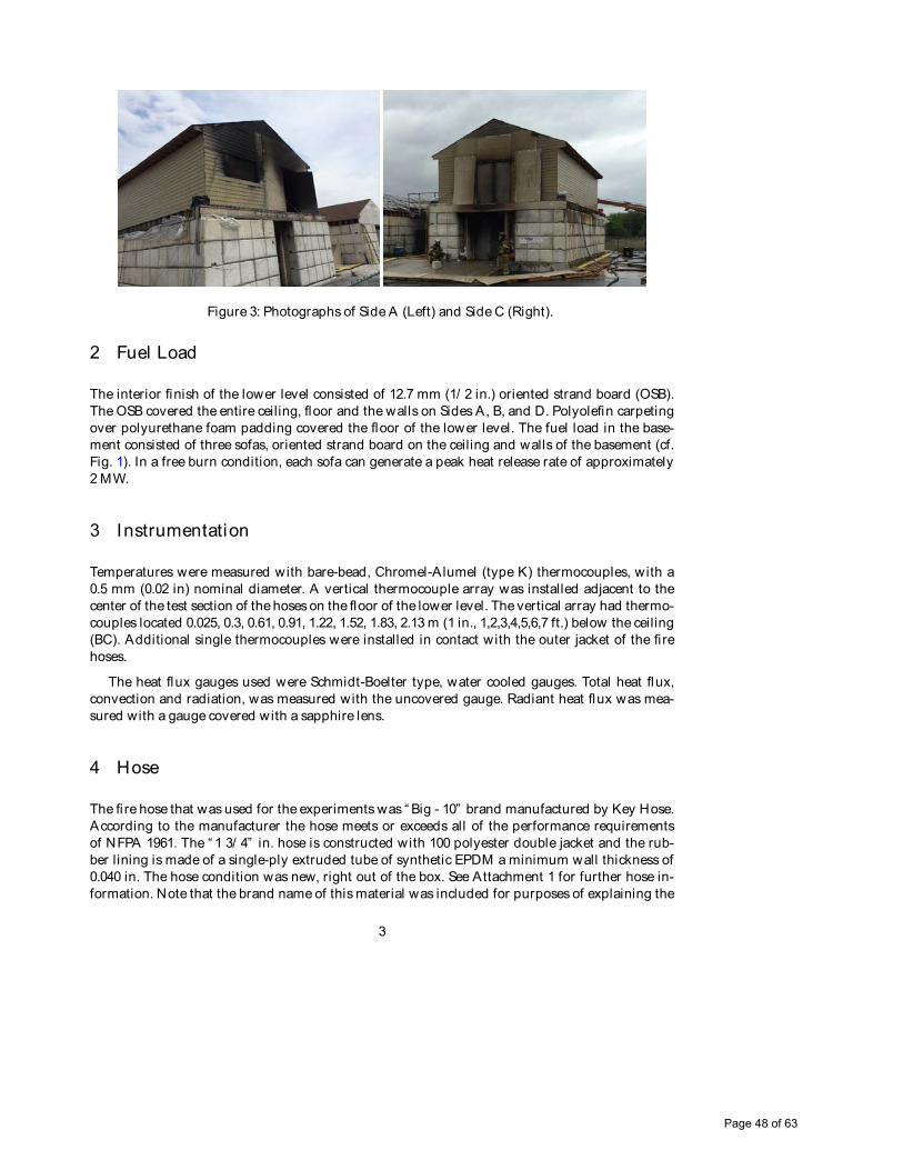
Figure 3: Photographs of Side A (Left) and Side C (Right).
2 Fuel Load
The interior finish of the lower level consisted of 12.7 mm (1/ 2 in.) oriented strand board (OSB).The OSB covered the entire ceiling, floor and the walls on Sides A, B, and D. Polyolefin carpetingover polyurethane foam padding covered the floor of the lower level. The fuel load in the base-ment consisted of three sofas, oriented strand board on the ceiling and walls of the basement (cf.Fig. 1). In a free burn condition, each sofa can generate a peak heat release rate of approximately2 MW.
3 Instrumentation
Temperatures were measured with bare-bead, Chromel-Alumel (type K) thermocouples, with a0.5 mm (0.02 in) nominal diameter. A vertical thermocouple array was installed adjacent to thecenter of the test section of the hoses on thefloor of the lower level. The vertical array had thermo-couples located 0.025, 0.3, 0.61, 0.91, 1.22, 1.52, 1.83, 2.13 m (1 in., 1,2,3,4,5,6,7 ft.) below the ceiling(BC). Additional single thermocouples were installed in contact with the outer jacket of the firehoses.
The heat flux gauges used were Schmidt-Boelter type, water cooled gauges. Total heat flux,convection and radiation, was measured with the uncovered gauge. Radiant heat flux was mea-sured with a gauge covered with a sapphire lens.
4 Hose
The fi re hose that was used for the experiments was “ Big - 10” brand manufactured by Key Hose.According to the manufacturer the hose meets or exceeds all of the performance requirementsof NFPA 1961. The “ 1 3/ 4” in. hose is constructed with 100 polyester double jacket and the rub-ber lining is made of a single-ply extruded tube of synthetic EPDM a minimum wall thickness of0.040 in. The hose condition was new, right out of the box. See Attachment 1 for further hose in-formation. Note that the brand name of this material was included for purposes of explaining the
3
Page 48 of 63

Figure 4: Fire room with fuel load, instrumentation and hose samples installed for Experiment 1.Looking in from the Side C open doorway on the lower level. These doors are the only openingin the structure during the test. As a result the fi re will move from the back of the room over theexposed hose toward the door.
experiment. Identification in this report isnot intended to imply recommendation or endorsementby NIST, nor is it intended to imply that such materials are necessarily the best available for thepurpose.
5 Resul ts
Two experiments were conducted to examine the amount of thermal exposure required to causethe fi re hose to burn through. In each experiment three different hose conditions were examined:hose fi l led with air, hose fi lled with water, hose flowing 150 gpm of water. The difference betweenthe two experiments was the location of the exposed hose section. In Experiment 1 the center ofthe exposed hose section and instrumentation was located 3.4 m (11.2 ft) from the open doorwayon Side C. In Experiment 2 the exposed hose section and instrumentation was located 1.2 m (4 ft)from the open doorway on Side C.
In Experiment 1, all three hose samples failed during the transition to flashover. Given the highrate of change of the thermal exposure in Experiment 1, the exposed section was moved closer tothe open doorway for Experiment 2 as an attempt to reduce the exposure by taking advantage ofthe cool air being entrained near the floor through the open door way. In Experiment 2, the hosefi l led with air failed followed by the hose fi l led with static water. These two ruptures happened
4
Page 49 of 63

Figure 5: Locations of instrumented hose samples relative to the vertical thermocouple array, theheat flux gauge and the radiometer.
very close together in time. The water from the ruptured line suppressed the fi re to a degree andprotected the hose line with the flowing water, so that it did not fail although the outer jacket wasburned away and the hose was compromised.
6 Summary
These two experiments provide some insight in the level of energy required to burn through ahose. In both experiments, flames appeared to be close to the hose, if not impinging on the hose atthe time of burn through. In theseexperiments there was no significant difference in burn throughtime for the hoses fi lled with air, static water or flowing water.
5
Page 50 of 63

Figure 6: Photograph as the fi re room transitioned to flashover in Experiment 2.
6
Page 51 of 63

Figure 7: Photograph after Experiment 1. A ll three hoses burned through within 2 seconds of eachother. The hose at the top of the photograph was the static water line. The middle hose was fi l ledwith air. The lower hose is the hose that was flowing 150 gpm of water.
7
Page 52 of 63

Figure 8: Thermocouple temperatures as a function of elevation at the test section for Experiment1.
Figure 9: Total and radiant heat flux at the test section for Experiment 1.
8
Page 53 of 63

Figure 10: Thermocouple temperatures at the test section for each hose tested for Experiment 1.
9
Page 54 of 63

Figure 11: Photograph showing the damage to the hose samples after Experiment 2. The hose atthe top of the photograph was the static water line. The middle hose was fi l led with air. The lowerhose is the hose that was flowing 150 gpm of water.
10
Page 55 of 63

Figure 12: Thermocouple temperatures as a function of elevation at the test section for Experiment2.
Figure 13: Total and radiant heat flux at the test section for Experiment 2.
11
Page 56 of 63

Figure 14: Thermocouple temperatures at the test section for each hose tested for Experiment 2.
12
Page 57 of 63

Page 58 of 63
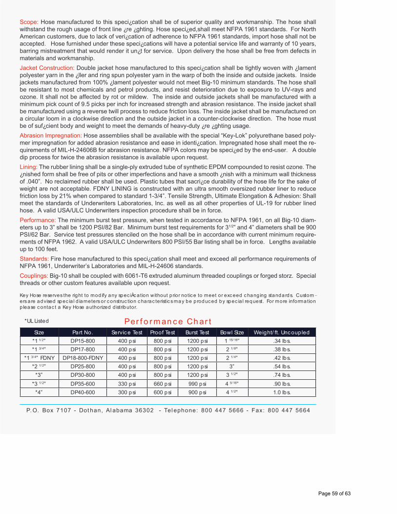
Scope: Hose manufactured to this speci¿cation shall be of superior quality and workmanship. The hose shall withstand the rough usage of front line ¿re ¿ghting. Hose speci¿ed,shall meet NFPA 1961 standards. For North American customers, due to lack of veri¿cation of adherence to NFPA 1961 standards, import hose shall not be accepted. Hose furnished under these speci¿cations will have a potential service life and warranty of 10 years, barring mistreatment that would render it un¿t for service. Upon delivery the hose shall be free from defects in materials and workmanship.
Jacket Construction: Double jacket hose manufactured to this speci¿cation shall be tightly woven with ¿lament polyester yarn in the ¿ller and ring spun polyester yarn in the warp of both the inside and outside jackets. Inside jackets manufactured from 100% ¿lament polyester would not meet Big-10 minimum standards. The hose shall be resistant to most chemicals and petrol products, and resist deterioration due to exposure to UV-rays and ozone. It shall not be affected by rot or mildew. The inside and outside jackets shall be manufactured with a minimum pick count of 9.5 picks per inch for increased strength and abrasion resistance. The inside jacket shall be manufactured using a reverse twill process to reduce friction loss. The inside jacket shall be manufactured on a circular loom in a clockwise direction and the outside jacket in a counter-clockwise direction. The hose must be of suf¿cient body and weight to meet the demands of heavy-duty ¿re ¿ghting usage.
Abrasion Impregnation: Hose assemblies shall be available with the special “Key-Lok” polyurethane based poly-mer impregnation for added abrasion resistance and ease in identi¿cation. Impregnated hose shall meet the re-quirements of MIL-H-24606B for abrasion resistance. NFPA colors may be speci¿ed by the end-user. A double dip process for twice the abrasion resistance is available upon request.
Lining: The rubber lining shall be a single-ply extruded tube of synthetic EPDM compounded to resist ozone. The ¿nished form shall be free of pits or other imperfections and have a smooth ¿nish with a minimum wall thickness of .040”. No reclaimed rubber shall be used. Plastic tubes that sacri¿ce durability of the hose life for the sake of weight are not acceptable. FDNY LINING is constructed with an ultra smooth oversized rubber liner to reduce friction loss by 21% when compared to standard 1-3/4”. Tensile Strength, Ultimate Elongation & Adhesion: Shall meet the standards of Underwriters Laboratories, Inc. as well as all other properties of UL-19 for rubber lined hose. A valid USA/ULC Underwriters inspection procedure shall be in force.
Performance: The minimum burst test pressure, when tested in accordance to NFPA 1961, on all Big-10 diam-eters up to 3” shall be 1200 PSI/82 Bar. Minimum burst test requirements for 31/2” and 4” diameters shall be 900 PSI/62 Bar. Service test pressures stenciled on the hose shall be in accordance with current minimum require-ments of NFPA 1962. A valid USA/ULC Underwriters 800 PSI/55 Bar listing shall be in force. Lengths available up to 100 feet.
Standards: Fire hose manufactured to this speci¿cation shall meet and exceed all performance requirements of NFPA 1961, Underwriter’s Laboratories and MIL-H-24606 standards.
Couplings: Big-10 shall be coupled with 6061-T6 extruded aluminum threaded couplings or forged storz. Special threads or other custom features available upon request.
Size Part No. Servic e Test Proof Test Burst Test Bowl Size Weight/ ft. Uncoupled
*1 1/ 2” DP15-800 400 psi 800 psi 1200 psi 1 15/ 16” .34 lbs.
*1 3/ 4” DP17-800 400 psi 800 psi 1200 psi 2 1/ 8” .38 lbs.
*1 3/ 4” FDNY DP18-800-FDNY 400 psi 800 psi 1200 psi 2 1/ 4” .42 lbs.
*2 1/ 2” DP25-800 400 psi 800 psi 1200 psi 3” .54 lbs.
*3” DP30-800 400 psi 800 psi 1200 psi 3 1/ 2” .74 lbs.
*3 1/ 2” DP35-600 330 psi 660 psi 990 psi 4 5/ 16” .90 lbs.
*4” DP40-600 300 psi 600 psi 900 psi 4 1/ 2” 1.0 lbs.
Per f o r m an c e Ch ar t*UL Listed
P. O. Box 7107 - Dot han, Al abama 36302 - Tel ephone: 800 447 5666 - Fax: 800 447 5664
Key Hose reserves the right to mod ify any spec iÀc ation without p rior notic e to meet or exc eed c hang ing standards. Custom-ers a re advised spec ia l d iameters or c onstruc tion c harac teristic s may be p roduc ed by spec ia l request. For more information p lease c ontac t a Key Hose authorized d istributor.
Page 59 of 63

Public Comments for NFPA 1961
Page 60 of 63

Public Comment No. 2-NFPA 1961-2016 [ New Section after 3.3.4.4 ]
Booster Hose
A small diameter, rienforced, rubber or fabric covered, rubber lined, high or ultra pressure hose.
Statement of Problem and Substantiation for Public Comment
This is the definition of Booster hose copied (modified "fabric" covered, "ultra" high pressure) from NFPA1961 1979 edition. I feel that we need to reintroduce booster hose into the 1961 standard now as high and ultra high pressure booster reels are making a come back on fire apparatus as is evident in the 2016 edition of the NFPA1901 standard specifically addressing High and Ultra high pressure pumps in the new standard. These apparatus are out there being used with booster hose that is not addressed in the hose standard.
Related Item
Committee Input No. 9-NFPA 1961-2015 [New Section after 3.3.4.7]
Submitter Information Verification
Submitter Full Name: Paul Prevost
Organization: Clearwater Regional Fire Rescu
Street Address:
City:
State:
Zip:
Submittal Date: Mon May 02 09:06:15 EDT 2016
National Fire Protection Association Report http://submittals.nfpa.org/TerraViewWeb/ContentFetcher?commentPara...
1 of 3 5/17/2016 8:22 AM
Page 61 of 63

Public Comment No. 3-NFPA 1961-2016 [ New Section after 4.5 ]
Booster Hose
Booster Hose.
Conventional booster hose shall comply with the requirements of ANSI/UL 92, Fire Extinguisher andBooster Hose.
High pressure booster hose, intended for acceptance pressure test over 400 psi (2760 kPa), shallcomply with the requirements of Rubber Manufacturers Association Standard for High Pressure Fire EngineBooster and Fire Extinguisher Hose.
Statement of Problem and Substantiation for Public Comment
I think that we need to add booster hose back into the standard to address the growing popularity of high and ultra high booster reels and pumps to modern apparatus. This trend is reflected by the latest edition of the 1901 standard defining high and ultra high pressure pumps in the new edition. I feel it is a disservice to not address this type of hose in the fire hose standard.
Related Item
Committee Input No. 9-NFPA 1961-2015 [New Section after 3.3.4.7]
Submitter Information Verification
Submitter Full Name: Paul Prevost
Organization: Clearwater Regional Fire Rescu
Street Address:
City:
State:
Zip:
Submittal Date: Mon May 02 09:28:23 EDT 2016
National Fire Protection Association Report http://submittals.nfpa.org/TerraViewWeb/ContentFetcher?commentPara...
2 of 3 5/17/2016 8:22 AM
Page 62 of 63

Public Comment No. 4-NFPA 1961-2016 [ New Section after B.1.2 ]
ANSI/UL Publications
ANSI/UL 92-1993-2008. Fire Extinguisher and Booster Hose,
Statement of Problem and Substantiation for Public Comment
reference document for booster hose copied from the 1979 hose standard latest revision.
Related Item
Committee Input No. 9-NFPA 1961-2015 [New Section after 3.3.4.7]
Submitter Information Verification
Submitter Full Name: Paul Prevost
Organization: Clearwater Regional Fire Rescu
Street Address:
City:
State:
Zip:
Submittal Date: Mon May 02 09:44:39 EDT 2016
National Fire Protection Association Report http://submittals.nfpa.org/TerraViewWeb/ContentFetcher?commentPara...
3 of 3 5/17/2016 8:22 AM
Page 63 of 63