Embed Size (px)
DESCRIPTION
AU400- BC- Technical Information
Citation preview
M514 TECHNICAL INFORMATION TABLE OF CONTENTS
st_tc_01.DOC
TITLE and CONTENTS Number of Page
1. PROService Setup
1-1. DPR Setup Procedure ........................................................................44
2. Measurement Temperature of GA Unit.........................................................1
0-1
1.PROService Set up
1-1. DPR Setup Procedures
Software Engineering Group
Product Development Department Beckman Coulter K.K.

PROService DPR Setup Procedures
i
Contents 1 INTRODUCTION ....................................................................................................................................................1-1
2 FLOW OF SETUP ....................................................................................................................................................2-1
3 PRE-INSTALLATION .............................................................................................................................................3-1 3.1 USERS’ CONFIRMATION AND CONSENT FOR CONNECTION OF PROSERVICE EQUIPMENT......................3-1 3.2 CHECK EXISTENCE OF HTTP HEADER FILTER AND PROXY SERVER ......................................................3-2 3.3 CHECK THE LAN CABLE TO BE USED ...................................................................................................3-2 3.4 CHECK POWER OUTLET ........................................................................................................................3-3 3.5 CHECK THE DPR PROGRAM VERSION...................................................................................................3-3 3.6 CHECK THE REGISTRATION ON THE PROSERVICE SERVER ..................................................................3-3 3.7 CHECK THE PASSWORD OF EACH SOFTWARE APPLICATION ...................................................................3-3
4 PREPARATION........................................................................................................................................................4-1
5 HARDWARE INSTALLATION..............................................................................................................................5-1 5.1 INSTALL LAN CARD..............................................................................................................................5-1 5.2 INSTALL LAN DRIVER ..........................................................................................................................5-1 5.3 CONNECT ROUTER................................................................................................................................5-1
6 NETWORK CONFIGURATION............................................................................................................................6-1 6.1 ASSIGNING FIXED IP ADDRESS .............................................................................................................6-1 6.2 USING DHCP TO ASSIGN IP AUTOMATICALLY ......................................................................................6-2
7 INSTALLATION OF SOFTWARE.........................................................................................................................7-1
8 PARAMETER SETTING ........................................................................................................................................8-1 8.1 SETTING DPR.......................................................................................................................................8-1 8.2 SETTING COMMUNICATOR....................................................................................................................8-2
9 OPERATION CHECK.............................................................................................................................................9-1
10 GLOSSARY.............................................................................................................................................................10-1 10.1 PROXY SERVER ...................................................................................................................................10-1 10.2 TYPE OF LAN CABLES ........................................................................................................................10-2
11 REVISION HISTORY............................................................................................................................................ 11-1

PROService DPR Setup Procedures
1-1
1 Introduction
Audience This document describes setup procedures and is intended for service personnel who
will set up the PROService.
PROService DPR Setup Procedures
2-1
2 Flow of Setup
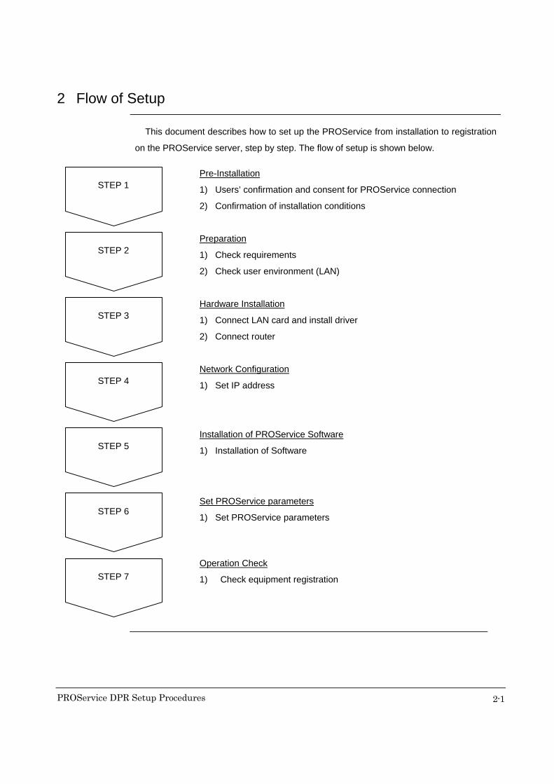
This document describes how to set up the PROService from installation to registration
on the PROService server, step by step. The flow of setup is shown below.
STEP 1
Pre-Installation
1) Users’ confirmation and consent for PROService connection
2) Confirmation of installation conditions
STEP 2
Preparation
1) Check requirements
2) Check user environment (LAN)
STEP 3
Hardware Installation
1) Connect LAN card and install driver
2) Connect router
STEP 4
Network Configuration
1) Set IP address
STEP 5
STEP 6
STEP 7
Installation of PROService Software
1) Installation of Software
Operation Check
1) Check equipment registration
Set PROService parameters
1) Set PROService parameters
PROService DPR Setup Procedures
3-1
3 Pre-Installation
3.1 Users’ confirmation and consent for connection of PROService equipment
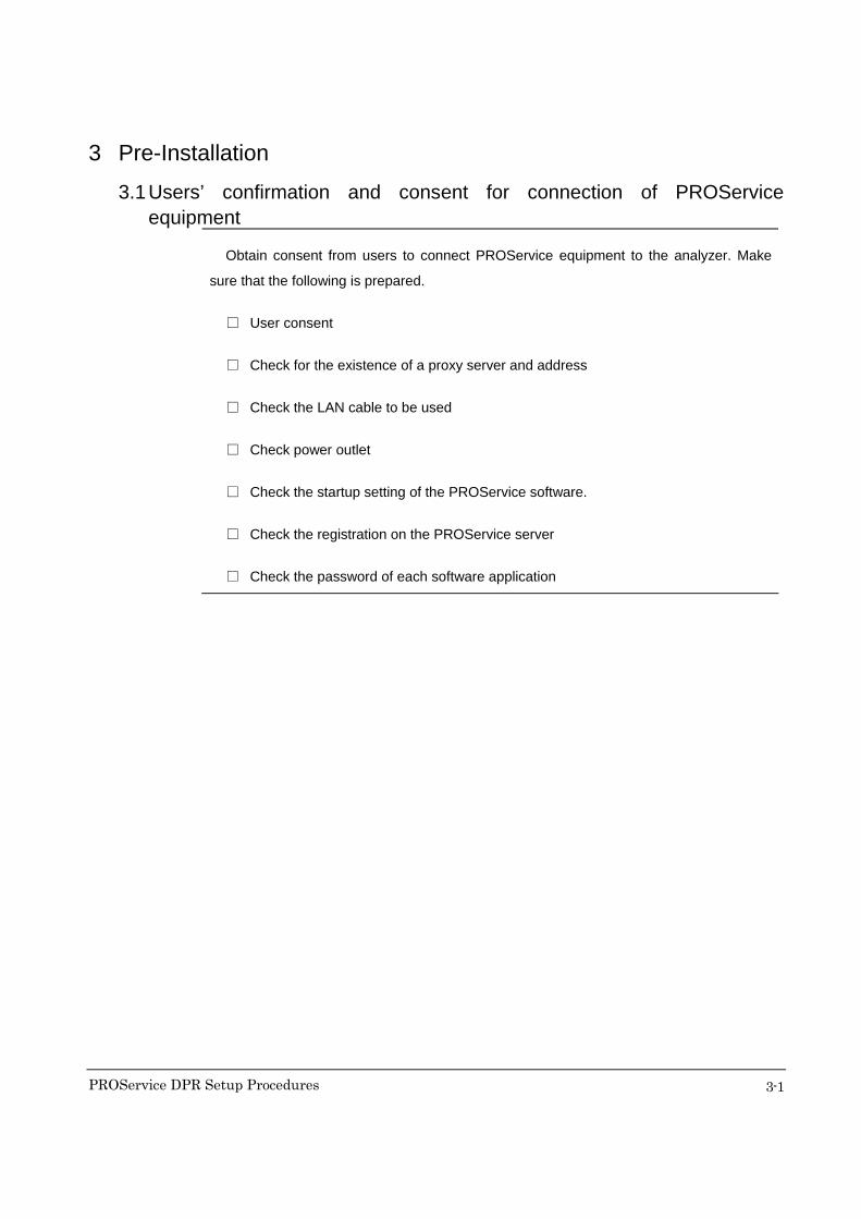
Obtain consent from users to connect PROService equipment to the analyzer. Make
sure that the following is prepared.
□ User consent
□ Check for the existence of a proxy server and address
□ Check the LAN cable to be used
□ Check power outlet
□ Check the startup setting of the PROService software.
□ Check the registration on the PROService server
□ Check the password of each software application
PROService DPR Setup Procedures
3-2
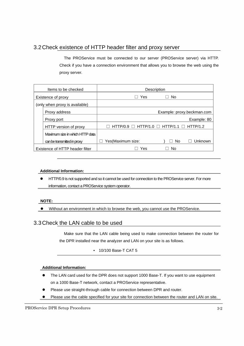
3.2 Check existence of HTTP header filter and proxy server The PROService must be connected to our server (PROService server) via HTTP.
Check if you have a connection environment that allows you to browse the web using the
proxy server.
Items to be checked Description
Existence of proxy □ Yes □ No
(only when proxy is available)
Proxy address Example: proxy.beckman.com
Proxy port Example: 80
HTTP version of proxy □ HTTP/0.9 □ HTTP/1.0 □ HTTP/1.1 □ HTTP/1.2
Maximum size in which HTTP data
can be transmitted in proxy
□ Yes(Maximum size: ) □ No □ Unknown
Existence of HTTP header filter □ Yes □ No
Additional Information:
HTTP/0.9 is not supported and so it cannot be used for connection to the PROService server. For more
information, contact a PROService system operator.
NOTE:
Without an environment in which to browse the web, you cannot use the PROService.
3.3 Check the LAN cable to be used Make sure that the LAN cable being used to make connection between the router for
the DPR installed near the analyzer and LAN on your site is as follows.
• 10/100 Base-T CAT 5
Additional Information:
The LAN card used for the DPR does not support 1000 Base-T. If you want to use equipment
on a 1000 Base-T network, contact a PROService representative.
Please use straight-through cable for connection between DPR and router.
Please use the cable specified for your site for connection between the router and LAN on site.

PROService DPR Setup Procedures
3-3
3.4 Check power outlet A power outlet is needed for router when installing the PROService. Make sure that the
outlet has a vacancy.
3.5 Check the DPR program version Please confirm the program version of DPR. The program version should corresponded
to PROService version 2.0.
3.6 Check the registration on the PROService server Check whether there is an analyzer registered on the PROService server.
3.7 Check the password of each software application Check the passwords of the following software applications.
・ AUDPRSetting
・ CommunicatorSetting
PROService DPR Setup Procedures
4-1
4 Preparation
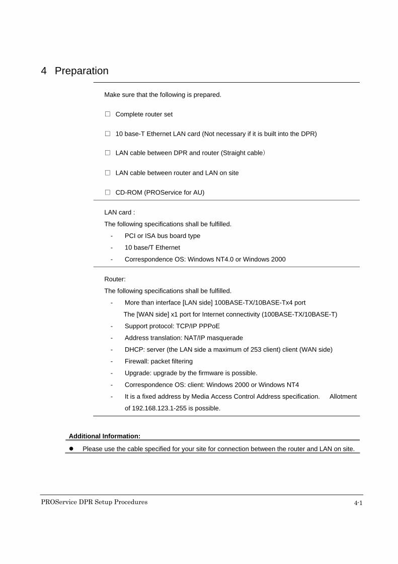
Make sure that the following is prepared.
□ Complete router set
□ 10 base-T Ethernet LAN card (Not necessary if it is built into the DPR)
□ LAN cable between DPR and router (Straight cable)
□ LAN cable between router and LAN on site
□ CD-ROM (PROService for AU)
LAN card : The following specifications shall be fulfilled.
- PCI or ISA bus board type
- 10 base/T Ethernet
- Correspondence OS: Windows NT4.0 or Windows 2000
Router:
The following specifications shall be fulfilled.
- More than interface [LAN side] 100BASE-TX/10BASE-Tx4 port
The [WAN side] x1 port for Internet connectivity (100BASE-TX/10BASE-T)
- Support protocol: TCP/IP PPPoE
- Address translation: NAT/IP masquerade
- DHCP: server (the LAN side a maximum of 253 client) client (WAN side)
- Firewall: packet filtering
- Upgrade: upgrade by the firmware is possible.
- Correspondence OS: client: Windows 2000 or Windows NT4
- It is a fixed address by Media Access Control Address specification. Allotment
of 192.168.123.1-255 is possible.
Additional Information:
Please use the cable specified for your site for connection between the router and LAN on site.

PROService DPR Setup Procedures
5-1
5 Hardware installation
5.1 Install LAN card
Install LAN card for PROService onto DPR.
Additional Information:
For more information on installation of the LAN card, refer to the instruction manuals for the
DPR (personal computer) and LAN card.
If a LAN card is built into the DPR, you do not have to install a LAN card. To enable the LAN
card that is built into the DPR, refer to the instruction manual for the DPR (personal computer).
5.2 Install LAN driver
Install the LAN driver on DPR.
Additional Information:
To install a LAN driver, refer to the instruction manual for the LAN card.
5.3 Connect router 1) Connect the router according to the diagram below.
2) Connect the LAN connector of the DPR and the LAN connector of the router with a
LAN cable.
NOTE:
The LAN in the facilities should be connected after parameters have been set. In order to
avoid LAN failure, do not connect to the LAN in the facilities until it is formerly in operation.
Router
DPR (personal)
LAN in the facilities

PROService DPR Setup Procedures
6-1
6 Network Configuration
Configure the network on the DPR side. Configuration depends on having a fixed IP
address or a dynamic IP with DHCP for the DPR.
6.1 Assigning fixed IP address 1) Open Properties of the “Local Area Connection” from the “Control Panel” –
“Network Connections”.
2) Select “Internet Protocol (TCP/IP)” and open “Properties”.
3) Select the [Use the following IP address] check box.
4) Enter the specified IP address in “[IP Address]”.
5) Click the “OK” button.
6) Close the “Properties” window of “Local Area Connection”.
3) 4)
PROService DPR Setup Procedures
6-2
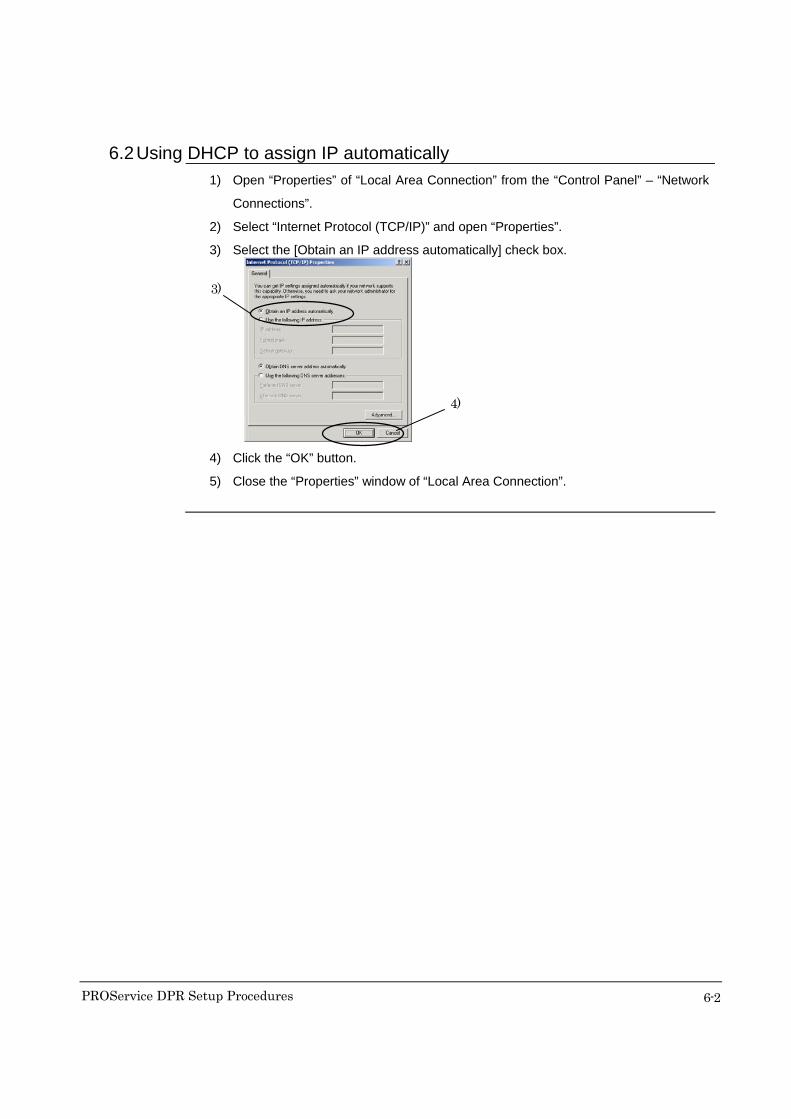
6.2 Using DHCP to assign IP automatically 1) Open “Properties” of “Local Area Connection” from the “Control Panel” – “Network
Connections”.
2) Select “Internet Protocol (TCP/IP)” and open “Properties”.
3) Select the [Obtain an IP address automatically] check box.
4) Click the “OK” button.
5) Close the “Properties” window of “Local Area Connection”.
3)
4)
PROService DPR Setup Procedures
7-1
7 Installation of Software
Installation
procedure
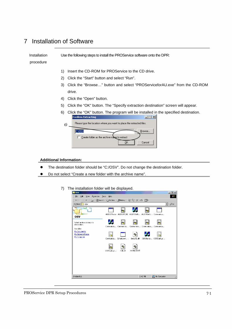
Use the following steps to install the PROService software onto the DPR:
1) Insert the CD-ROM for PROService to the CD drive.
2) Click the “Start” button and select “Run”.
3) Click the “Browse…” button and select “PROServiceforAU.exe” from the CD-ROM
drive.
4) Click the “Open” button.
5) Click the “OK” button. The “Specify extraction destination” screen will appear.
6) Click the “OK” button. The program will be installed in the specified destination.
Additional Information:
The destination folder should be “C:/OSV”. Do not change the destination folder.
Do not select “Create a new folder with the archive name”.
7) The installation folder will be displayed.
6)

PROService DPR Setup Procedures
7-2
Additional Information:
If the specified folder does not exist, the following screen will appear. Click the “OK” button to
create the specified folder and install the program into it.
PROService DPR Setup Procedures
8-1
8 Parameter Setting
Set the PROService parameters using the following procedure.
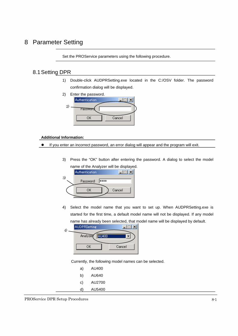
8.1 Setting DPR 1) Double-click AUDPRSetting.exe located in the C:/OSV folder. The password
confirmation dialog will be displayed.
2) Enter the password.
Additional Information:
If you enter an incorrect password, an error dialog will appear and the program will exit.
3) Press the “OK” button after entering the password. A dialog to select the model
name of the Analyzer will be displayed.
4) Select the model name that you want to set up. When AUDPRSetting.exe is
started for the first time, a default model name will not be displayed. If any model
name has already been selected, that model name will be displayed by default.
Currently, the following model names can be selected.
a) AU400
b) AU640
c) AU2700
d) AU5400
2)
3)
4)
PROService DPR Setup Procedures
8-2
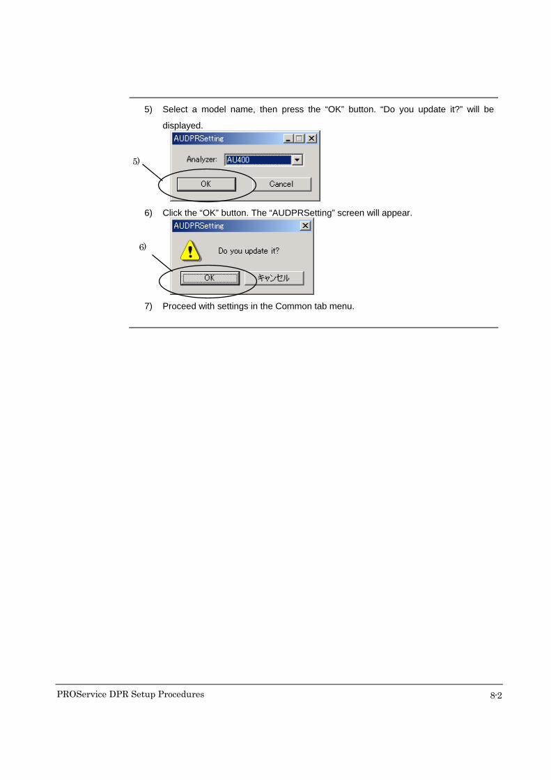
5) Select a model name, then press the “OK” button. “Do you update it?” will be
displayed.
6) Click the “OK” button. The “AUDPRSetting” screen will appear.
7) Proceed with settings in the Common tab menu.
5)
6)

PROService DPR Setup Procedures
8-3
Setting Common tab menu Set Common tab screen.
1) Check the [Connect PROService].
2) Check the [Enable SID Mask].
3) Check the [Enable Other Mask].
4) Proceed with setting of Translated tab menu.
Additional Information:
Detail on Common tab menu is as shown below.
・ PROService connection
Connect PROService :Check this when connecting to PROService server.
・ Mask Setting
Enable SID Mask :Check this to enable SID mask.
Enable Other Mask :Check this to enable other masks.
1)
2)
3)
4)

PROService DPR Setup Procedures
8-4
Setting Translated tab menu Set Translated tab screen.
1) Refer to “Detail on setting Translated tab menu” and change the settings.
Additional Information:
Detail on Translated tab menu is as shown below.
・ Translated Item
F3:Print :Check the “Refer to the details on setting Translated tub menu”.
etc. :Check the “Refer to the details on setting Translated tub menu”.
1)

PROService DPR Setup Procedures
8-5
Saving the setting contents Save the setting contents
1) Click the “Exit” button.
2) The message of “Save parameter?” is displayed. Click the “Yes” button. The setting
contents are saved. If the “No” button is clicked then the setting contents are not
saved.
3) The message of “Printout parameter?” is displayed. Click the “OK” button. The
setting contents are printed. If the “Cancel” button is clicked then the setting
contents are not printed.
Additional Information:
The “File” menu and button functions are as follows.
・ “File” menu
Import :Call back the settings (ini file) previously exported.
Save :Save the settings.
Export :Output the settings to a specific file (ini file).
・ “Default” button :Default settings will be restored.
・ “Exit” button :Exit the setting screen.
1)

PROService DPR Setup Procedures
8-6
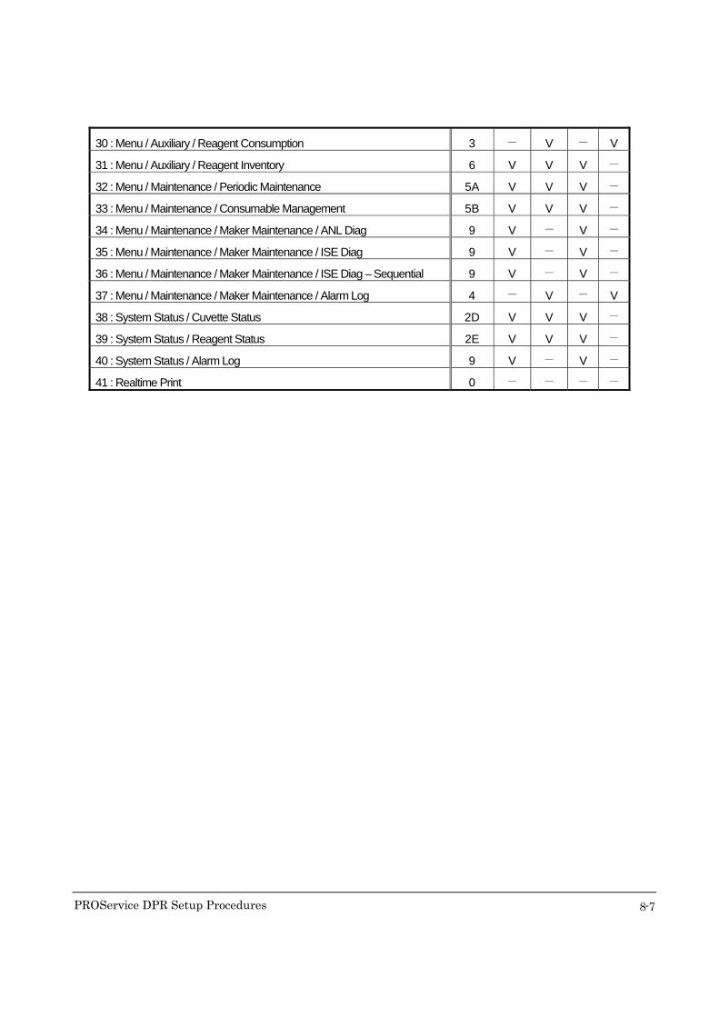
Detail on setting Translated tab menu
[AU400]
Set Selectability Default
Item Names Type F3 etc. F3 etc.
01 : Menu / Routine / Test Requisition / Normal 0 - - - -
02 : Menu / Routine / Test Requisition / Repeat 0 - - - -
03 : Menu / Routine / Reaction Monitor 9 V - V -
04 : Menu / Routine / Photocal Monitor 2A V V V -
05 : Menu / Routine / Calibration Monitor / Calibration Curve 2B V V V -
06 : Menu / Routine / Calibration Monitor / Reagent Blank Monitor 2C V V V -
07 : Menu / Routine / QC Monitor / Daily Control 9 V - V -
08 : Menu / Routine / QC Monitor / Day to Day Control 9 V - V -
09 : Menu / Routine / Repeat Data Verification 0 - - - -
10 : Menu / Parameter / Common Test Parameters / Test Name 1 V V V V
11 : Menu / Parameter / Common Test Parameters / Profile 1 V V V V
12 : Menu / Parameter / Specific Test Parameters 1 V V V V
13 : Menu / Parameter / Inter-related Tests / Calculated Tests 1 V V V V
14 : Menu / Parameter / Inter-related Tests / Checked Tests 1 V V V V
15 : Menu / Parameter / Repeat Parameters / Repeat Specific 1 V V V V
16 : Menu / Parameter / QC Control / QC Common 1 V V V V
17 : Menu / Parameter / QC Control / QC Specific 1 V V V V
18 : Menu / Parameter / Calibration / Calibrator 1 V V V V
19 : Menu / Parameter / Calibration / Calibration Specific 1 V V V V
20 : Menu / Parameter / Online 1 V V V V
21 : Menu / Parameter / Format / Report Format 1 V V V V
22 : Menu / Parameter / Special / Contamination Parameters 1 V V V V
23 : Menu / Parameter / Special / Data Check Parameters 1 V V V V
24 : Menu / Parameter / Comment Masters 1 V V V V
25 : Menu / Parameter / Calibration / STAT Table Calibration 1 V V V V
26 : Menu / Parameter / QC Control / STAT Table QC 1 V V V V
27 : Menu / Auxiliary / Data Statistics 9 V - V -
28 : Menu / Auxiliary / Histogram 9 V - V -
29 : Menu / Auxiliary / Histogram – Sequential 9 V - V -
PROService DPR Setup Procedures
8-7
30 : Menu / Auxiliary / Reagent Consumption 3 - V - V
31 : Menu / Auxiliary / Reagent Inventory 6 V V V -
32 : Menu / Maintenance / Periodic Maintenance 5A V V V -
33 : Menu / Maintenance / Consumable Management 5B V V V -
34 : Menu / Maintenance / Maker Maintenance / ANL Diag 9 V - V -
35 : Menu / Maintenance / Maker Maintenance / ISE Diag 9 V - V -
36 : Menu / Maintenance / Maker Maintenance / ISE Diag – Sequential 9 V - V -
37 : Menu / Maintenance / Maker Maintenance / Alarm Log 4 - V - V
38 : System Status / Cuvette Status 2D V V V -
39 : System Status / Reagent Status 2E V V V -
40 : System Status / Alarm Log 9 V - V -
41 : Realtime Print 0 - - - -

PROService DPR Setup Procedures
8-8
[AU640]
Set Selectability Default
Item Names Type F3 etc. F3 etc.
01 : Menu / Routine / Test Requisition / Normal 0 - - - -
02 : Menu / Routine / Test Requisition / Repeat 0 - - - -
03 : Menu / Routine / Reaction Monitor 9 V - V -
04 : Menu / Routine / Photocal Monitor 2A V V V -
05 : Menu / Routine / Calibration Monitor / Calibration Curve 2B V V V -
06 : Menu / Routine / Calibration Monitor / Reagent Blank Monitor 2C V V V -
07 : Menu / Routine / QC Monitor / Daily Control 9 V - V -
08 : Menu / Routine / QC Monitor / Day to Day Control 9 V - V -
09 : Menu / Routine / Repeat Data Verification 0 - - - -
10 : Menu / Parameter / Common Test Parameters / Test Name 1 V V V V
11 : Menu / Parameter / Common Test Parameters / Profile 1 V V V V
12 : Menu / Parameter / Specific Test Parameters 1 V V V V
13 : Menu / Parameter / Inter-related Tests / Calculated Tests 1 V V V V
14 : Menu / Parameter / Inter-related Tests / Checked Tests 1 V V V V
15 : Menu / Parameter / Repeat Parameters / Repeat Specific 1 V V V V
16 : Menu / Parameter / QC Control / QC Common 1 V V V V
17 : Menu / Parameter / QC Control / QC Specific 1 V V V V
18 : Menu / Parameter / Calibration / Calibrator 1 V V V V
19 : Menu / Parameter / Calibration / Calibration Specific 1 V V V V
20 : Menu / Parameter / Online 1 V V V V
21 : Menu / Parameter / Format / Report Format 1 V V V V
22 : Menu / Parameter / Special / Contamination Parameters 1 V V V V
23 : Menu / Parameter / Special / Data Check Parameters 1 V V V V
24 : Menu / Parameter / Comment Masters 1 V V V V
25 : Menu / Parameter / Calibration / STAT Table Calibration 1 V V V V
26 : Menu / Parameter / QC Control / STAT Table QC 1 V V V V
27 : Menu / Auxiliary / Data Statistics 9 V - V -
28 : Menu / Auxiliary / Histogram 9 V - V -
29 : Menu / Auxiliary / Histogram – Sequential 9 V - V -
30 : Menu / Auxiliary / Reagent Consumption 3 - V - V
31 : Menu / Auxiliary / Reagent Inventory 6 V V V -

PROService DPR Setup Procedures
8-9
32 : Menu / Maintenance / Periodic Maintenance 5A V V V -
33 : Menu / Maintenance / Consumable Management 5B V V V -
34 : Menu / Maintenance / Maker Maintenance / ANL Diag 9 V - V -
35 : Menu / Maintenance / Maker Maintenance / ISE Diag 9 V - V -
36 : Menu / Maintenance / Maker Maintenance / ISE Diag – Sequential 9 V - V -
37 : Menu / Maintenance / Maker Maintenance / Alarm Log 4 - V - V
38 : System Status / Cuvette Status 2D V V V -
39 : System Status / Reagent Status 2E V V V -
40 : System Status / Alarm Log 9 V - V -
41 : Realtime Print 0 - - - -
PROService DPR Setup Procedures
8-10
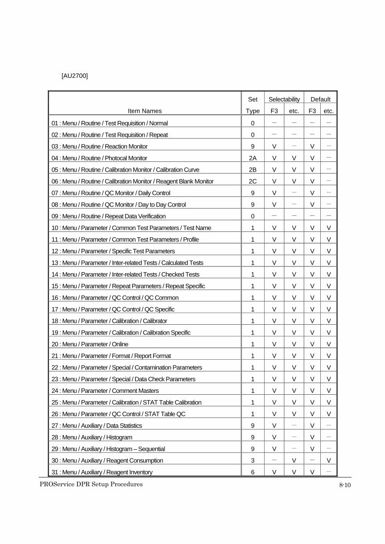
[AU2700]
Set Selectability Default
Item Names Type F3 etc. F3 etc.
01 : Menu / Routine / Test Requisition / Normal 0 - - - -
02 : Menu / Routine / Test Requisition / Repeat 0 - - - -
03 : Menu / Routine / Reaction Monitor 9 V - V -
04 : Menu / Routine / Photocal Monitor 2A V V V -
05 : Menu / Routine / Calibration Monitor / Calibration Curve 2B V V V -
06 : Menu / Routine / Calibration Monitor / Reagent Blank Monitor 2C V V V -
07 : Menu / Routine / QC Monitor / Daily Control 9 V - V -
08 : Menu / Routine / QC Monitor / Day to Day Control 9 V - V -
09 : Menu / Routine / Repeat Data Verification 0 - - - -
10 : Menu / Parameter / Common Test Parameters / Test Name 1 V V V V
11 : Menu / Parameter / Common Test Parameters / Profile 1 V V V V
12 : Menu / Parameter / Specific Test Parameters 1 V V V V
13 : Menu / Parameter / Inter-related Tests / Calculated Tests 1 V V V V
14 : Menu / Parameter / Inter-related Tests / Checked Tests 1 V V V V
15 : Menu / Parameter / Repeat Parameters / Repeat Specific 1 V V V V
16 : Menu / Parameter / QC Control / QC Common 1 V V V V
17 : Menu / Parameter / QC Control / QC Specific 1 V V V V
18 : Menu / Parameter / Calibration / Calibrator 1 V V V V
19 : Menu / Parameter / Calibration / Calibration Specific 1 V V V V
20 : Menu / Parameter / Online 1 V V V V
21 : Menu / Parameter / Format / Report Format 1 V V V V
22 : Menu / Parameter / Special / Contamination Parameters 1 V V V V
23 : Menu / Parameter / Special / Data Check Parameters 1 V V V V
24 : Menu / Parameter / Comment Masters 1 V V V V
25 : Menu / Parameter / Calibration / STAT Table Calibration 1 V V V V
26 : Menu / Parameter / QC Control / STAT Table QC 1 V V V V
27 : Menu / Auxiliary / Data Statistics 9 V - V -
28 : Menu / Auxiliary / Histogram 9 V - V -
29 : Menu / Auxiliary / Histogram – Sequential 9 V - V -
30 : Menu / Auxiliary / Reagent Consumption 3 - V - V
31 : Menu / Auxiliary / Reagent Inventory 6 V V V -
PROService DPR Setup Procedures
8-11
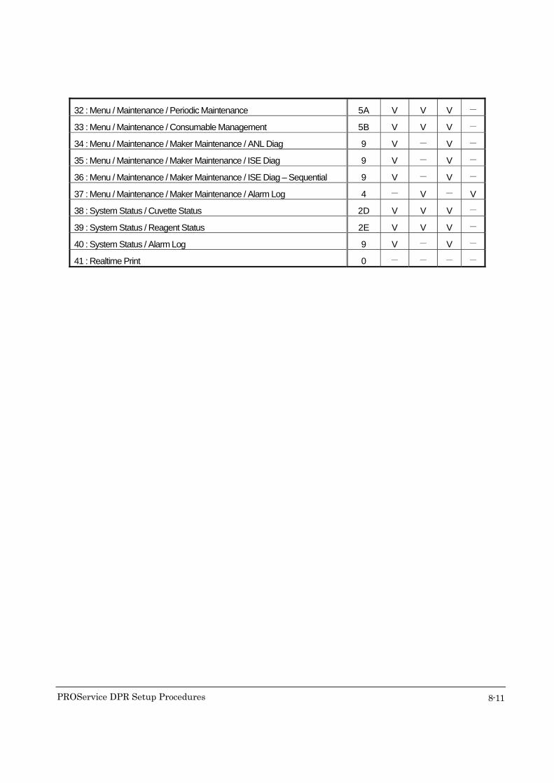
32 : Menu / Maintenance / Periodic Maintenance 5A V V V -
33 : Menu / Maintenance / Consumable Management 5B V V V -
34 : Menu / Maintenance / Maker Maintenance / ANL Diag 9 V - V -
35 : Menu / Maintenance / Maker Maintenance / ISE Diag 9 V - V -
36 : Menu / Maintenance / Maker Maintenance / ISE Diag – Sequential 9 V - V -
37 : Menu / Maintenance / Maker Maintenance / Alarm Log 4 - V - V
38 : System Status / Cuvette Status 2D V V V -
39 : System Status / Reagent Status 2E V V V -
40 : System Status / Alarm Log 9 V - V -
41 : Realtime Print 0 - - - -

PROService DPR Setup Procedures
8-12
[AU5400]
Set Selectability Default
Item Names Type F3 etc. F3 etc.
01 : Menu / Routine / Start Condition 9 V - V -
02 : Menu / Routine / Test Requisition / Normal 0 - - - -
03 : Menu / Routine / Test Requisition / Repeat 0 - - - -
04 : Menu / Routine / Reaction Monitor 9 V - V -
05 : Menu / Routine / Reaction Monitor Worked List 9 V - V -
06 : Menu / Routine / Photocal Monitor 2A V V V -
07 : Menu / Routine / Calibration Monitor / Calibration Curve 2B V V V -
08 : Menu / Routine / Calibration Monitor / Reagent Blank Monitor 2C V V V -
09 : Menu / Routine / QC Monitor / Daily Control 9 V - V -
10 : Menu / Routine / QC Monitor / Day to Day Control 9 V - V -
11 : Menu / Routine / Repeat Data Verification 0 - - - -
12 : Menu / Parameter / Common Test Parameters / Test Name 1 V V V V
13 : Menu / Parameter / Common Test Parameters / Profile 1 V V V V
14 : Menu / Parameter / Specific Test Parameters 1 V V V V
15 : Menu / Parameter / Inter-related Tests / Calculated Tests 1 V V V V
16 : Menu / Parameter / Inter-related Tests / Checked Tests 1 V V V V
17 : Menu / Parameter / Repeat Parameters / Repeat Specific 1 V V V V
18 : Menu / Parameter / QC Control / QC Common 1 V V V V
19 : Menu / Parameter / QC Control / QC Specific 1 V V V V
20 : Menu / Parameter / Calibration / Calibrator 1 V V V V
21 : Menu / Parameter / Calibration / Calibration Specific 1 V V V V
22 : Menu / Parameter / Online 1 V V V V
23 : Menu / Parameter / Format / Report Format 1 V V V V
24 : Menu / Parameter / Special / Contamination Parameters 1 V V V V
25 : Menu / Parameter / Special / Data Check Parameters 1 V V V V
26 : Menu / Parameter / Comment Masters 1 V V V V
27 : Menu / Parameter / QC Refrigerator 1 V V V V
28 : Menu / Auxiliary / Data Statistics 9 V - V -
29 : Menu / Auxiliary / Histogram 9 V - V -
30 : Menu / Auxiliary / Histogram – Sequential 9 V - V -
31 : Menu / Auxiliary / Reagent Consumption 3 - V - V
PROService DPR Setup Procedures
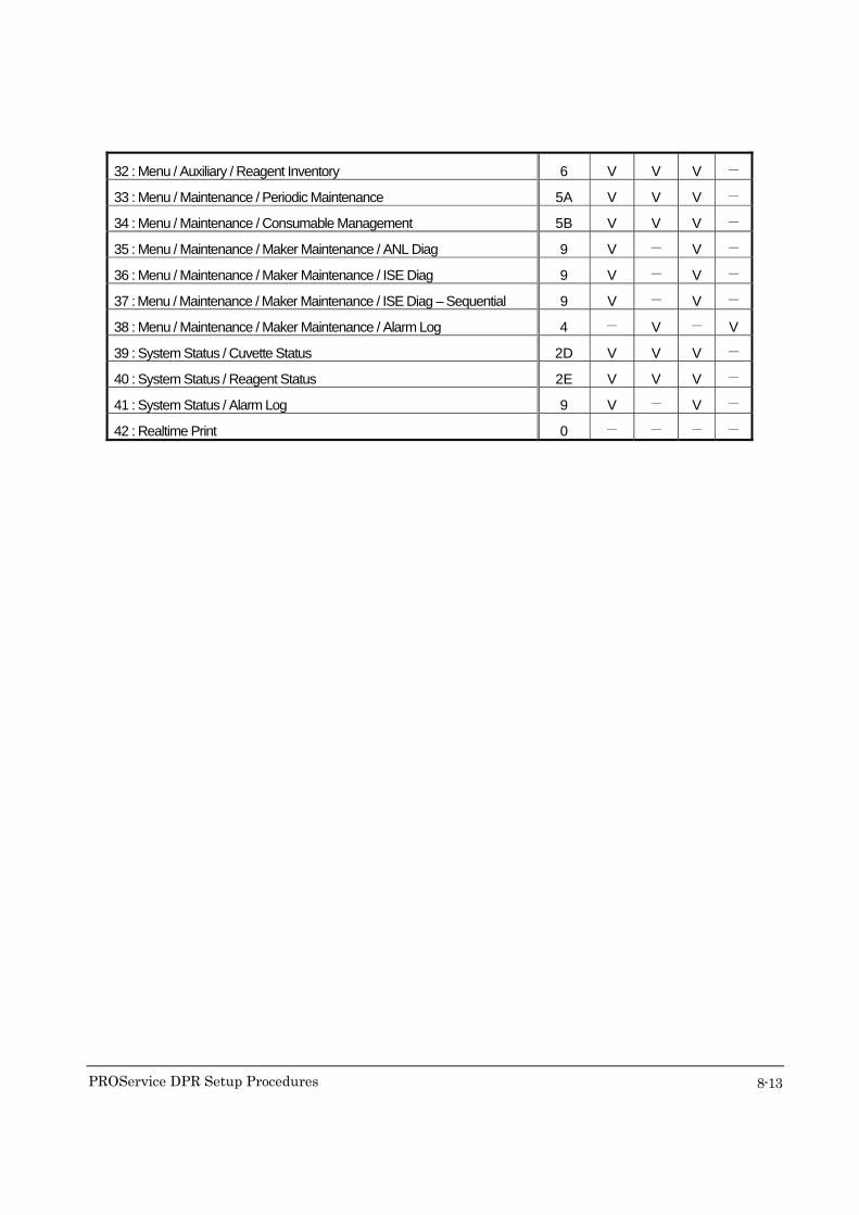
8-13
32 : Menu / Auxiliary / Reagent Inventory 6 V V V -
33 : Menu / Maintenance / Periodic Maintenance 5A V V V -
34 : Menu / Maintenance / Consumable Management 5B V V V -
35 : Menu / Maintenance / Maker Maintenance / ANL Diag 9 V - V -
36 : Menu / Maintenance / Maker Maintenance / ISE Diag 9 V - V -
37 : Menu / Maintenance / Maker Maintenance / ISE Diag – Sequential 9 V - V -
38 : Menu / Maintenance / Maker Maintenance / Alarm Log 4 - V - V
39 : System Status / Cuvette Status 2D V V V -
40 : System Status / Reagent Status 2E V V V -
41 : System Status / Alarm Log 9 V - V -
42 : Realtime Print 0 - - - -
PROService DPR Setup Procedures
8-14
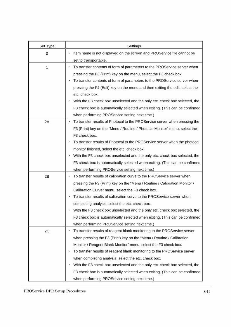
Set Type Settings
0 ・ Item name is not displayed on the screen and PROService file cannot be
set to transportable.
1 ・ To transfer contents of form of parameters to the PROService server when
pressing the F3 (Print) key on the menu, select the F3 check box.
・ To transfer contents of form of parameters to the PROService server when
pressing the F4 (Edit) key on the menu and then exiting the edit, select the
etc. check box.
・ With the F3 check box unselected and the only etc. check box selected, the
F3 check box is automatically selected when exiting. (This can be confirmed
when performing PROService setting next time.)
2A ・ To transfer results of Photocal to the PROService server when pressing the
F3 (Print) key on the “Menu / Routine / Photocal Monitor” menu, select the
F3 check box.
・ To transfer results of Photocal to the PROService server when the photocal
monitor finished, select the etc. check box.
・ With the F3 check box unselected and the only etc. check box selected, the
F3 check box is automatically selected when exiting. (This can be confirmed
when performing PROService setting next time.)
2B ・ To transfer results of calibration curve to the PROService server when
pressing the F3 (Print) key on the “Menu / Routine / Calibration Monitor /
Calibration Curve” menu, select the F3 check box.
・ To transfer results of calibration curve to the PROService server when
completing analysis, select the etc. check box.
・ With the F3 check box unselected and the only etc. check box selected, the
F3 check box is automatically selected when exiting. (This can be confirmed
when performing PROService setting next time.)
2C ・ To transfer results of reagent blank monitoring to the PROService server
when pressing the F3 (Print) key on the “Menu / Routine / Calibration
Monitor / Reagent Blank Monitor” menu, select the F3 check box.
・ To transfer results of reagent blank monitoring to the PROService server
when completing analysis, select the etc. check box.
・ With the F3 check box unselected and the only etc. check box selected, the
F3 check box is automatically selected when exiting. (This can be confirmed
when performing PROService setting next time.)
PROService DPR Setup Procedures
8-15
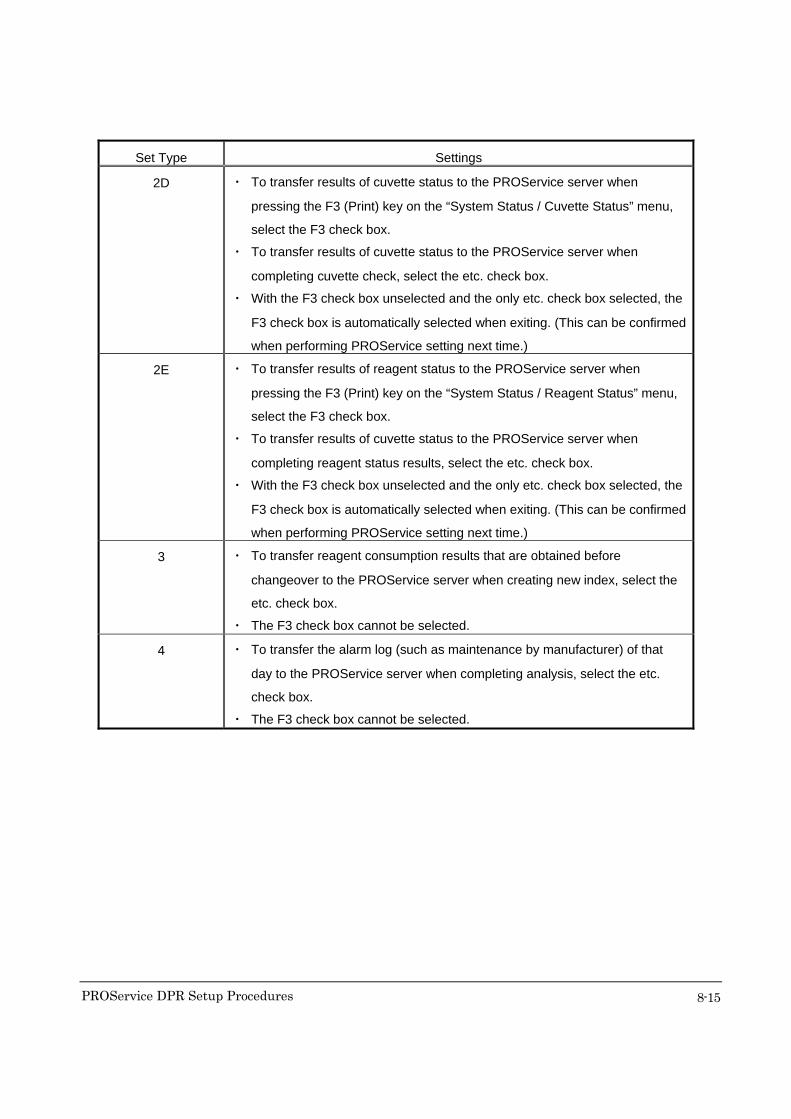
Set Type Settings
2D ・ To transfer results of cuvette status to the PROService server when
pressing the F3 (Print) key on the “System Status / Cuvette Status” menu,
select the F3 check box.
・ To transfer results of cuvette status to the PROService server when
completing cuvette check, select the etc. check box.
・ With the F3 check box unselected and the only etc. check box selected, the
F3 check box is automatically selected when exiting. (This can be confirmed
when performing PROService setting next time.)
2E ・ To transfer results of reagent status to the PROService server when
pressing the F3 (Print) key on the “System Status / Reagent Status” menu,
select the F3 check box.
・ To transfer results of cuvette status to the PROService server when
completing reagent status results, select the etc. check box.
・ With the F3 check box unselected and the only etc. check box selected, the
F3 check box is automatically selected when exiting. (This can be confirmed
when performing PROService setting next time.)
3 ・ To transfer reagent consumption results that are obtained before
changeover to the PROService server when creating new index, select the
etc. check box.
・ The F3 check box cannot be selected.
4 ・ To transfer the alarm log (such as maintenance by manufacturer) of that
day to the PROService server when completing analysis, select the etc.
check box.
・ The F3 check box cannot be selected.
PROService DPR Setup Procedures
8-1
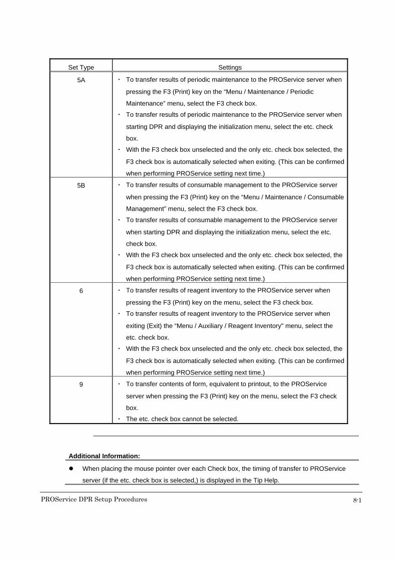
Set Type Settings
5A ・ To transfer results of periodic maintenance to the PROService server when
pressing the F3 (Print) key on the “Menu / Maintenance / Periodic
Maintenance” menu, select the F3 check box.
・ To transfer results of periodic maintenance to the PROService server when
starting DPR and displaying the initialization menu, select the etc. check
box.
・ With the F3 check box unselected and the only etc. check box selected, the
F3 check box is automatically selected when exiting. (This can be confirmed
when performing PROService setting next time.)
5B ・ To transfer results of consumable management to the PROService server
when pressing the F3 (Print) key on the “Menu / Maintenance / Consumable
Management” menu, select the F3 check box.
・ To transfer results of consumable management to the PROService server
when starting DPR and displaying the initialization menu, select the etc.
check box.
・ With the F3 check box unselected and the only etc. check box selected, the
F3 check box is automatically selected when exiting. (This can be confirmed
when performing PROService setting next time.)
6 ・ To transfer results of reagent inventory to the PROService server when
pressing the F3 (Print) key on the menu, select the F3 check box.
・ To transfer results of reagent inventory to the PROService server when
exiting (Exit) the “Menu / Auxiliary / Reagent Inventory" menu, select the
etc. check box.
・ With the F3 check box unselected and the only etc. check box selected, the
F3 check box is automatically selected when exiting. (This can be confirmed
when performing PROService setting next time.)
9 ・ To transfer contents of form, equivalent to printout, to the PROService
server when pressing the F3 (Print) key on the menu, select the F3 check
box.
・ The etc. check box cannot be selected.
Additional Information:
When placing the mouse pointer over each Check box, the timing of transfer to PROService
server (if the etc. check box is selected,) is displayed in the Tip Help.

PROService DPR Setup Procedures
8-2
8.2 Setting Communicator 1) Double-click CommunicatorSetting.exe located in C:/OSV folder. Password
confirmation dialog will be displayed.
2) Enter the password.
Additional Information:
If you enter incorrect password, the error dialog will appear and the program will exit.
3) Click the “OK” button after entering password. A dialog to select the model name of
Analyzer will be displayed.
4) Select the model name that you want to set up. When CommunicatorSetting.exe is
started for the first time, a default model name will not be displayed. If any model
name has already been selected, that model name will be displayed by default.
The following model names can be currently selected.
a) AU400
b) AU640
c) AU2700
d) AU5400
2)
4)
3)
PROService DPR Setup Procedures
8-3
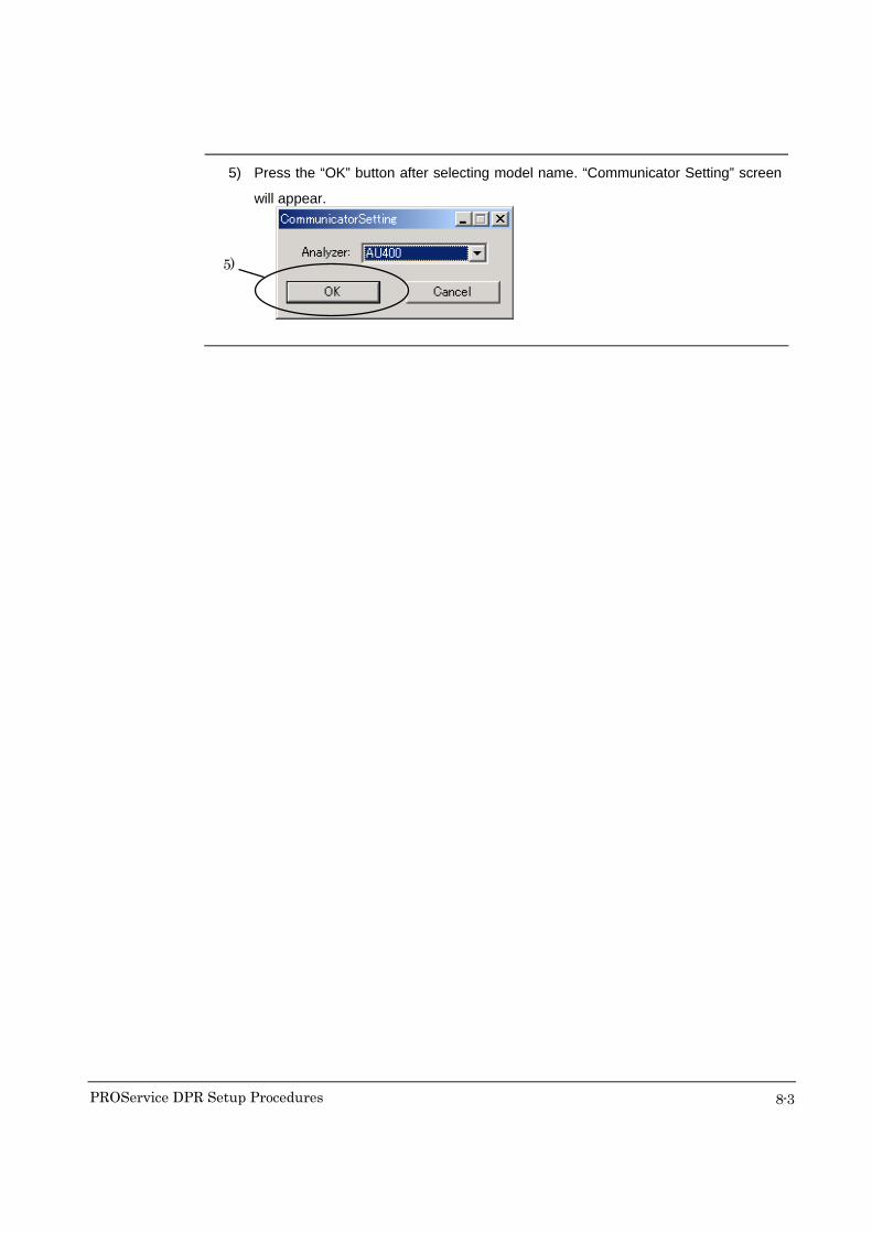
5) Press the “OK” button after selecting model name. “Communicator Setting” screen
will appear.
5)
PROService DPR Setup Procedures
8-1
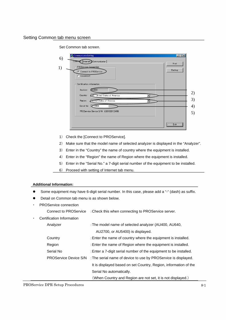
Setting Common tab menu screen Set Common tab screen.
1) Check the [Connect to PROService].
2) Make sure that the model name of selected analyzer is displayed in the “Analyzer”.
3) Enter in the “Country” the name of country where the equipment is installed.
4) Enter in the “Region” the name of Region where the equipment is installed.
5) Enter in the “Serial No.” a 7-digit serial number of the equipment to be installed.
6) Proceed with setting of Internet tab menu.
Additional Information:
Some equipment may have 6-digit serial number. In this case, please add a “-“ (dash) as suffix.
Detail on Common tab menu is as shown below.
・ PROService connection
Connect to PROService :Check this when connecting to PROService server.
・ Certification Information
Analyzer :The model name of selected analyzer (AU400, AU640,
AU2700, or AU5400) is displayed.
Country :Enter the name of country where the equipment is installed.
Region :Enter the name of Region where the equipment is installed.
Serial No :Enter a 7-digit serial number of the equipment to be installed.
PROService Device S/N :The serial name of device to use by PROService is displayed.
It is displayed based on set Country, Region, information of the
Serial No automatically.
(When Country and Region are not set, it is not displayed.)
1)
6)
2) 3) 4) 5)
PROService DPR Setup Procedures
8-2
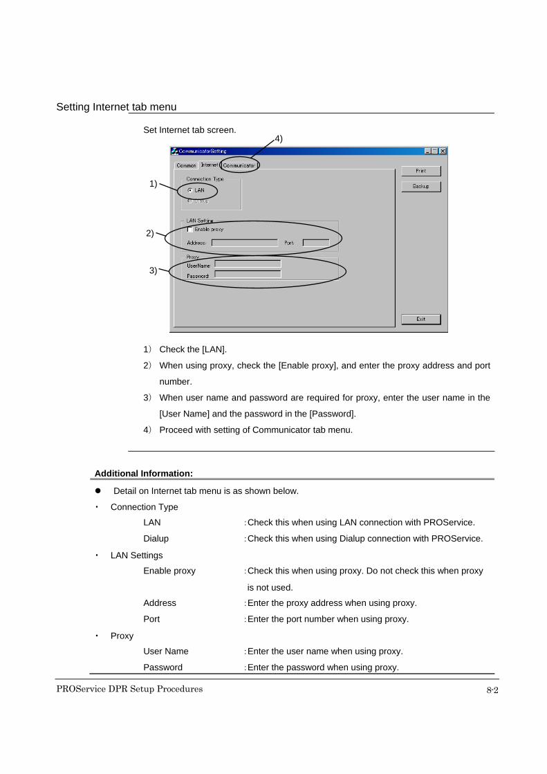
Setting Internet tab menu Set Internet tab screen.
1) Check the [LAN].
2) When using proxy, check the [Enable proxy], and enter the proxy address and port
number.
3) When user name and password are required for proxy, enter the user name in the
[User Name] and the password in the [Password].
4) Proceed with setting of Communicator tab menu.
Additional Information:
Detail on Internet tab menu is as shown below.
・ Connection Type
LAN :Check this when using LAN connection with PROService.
Dialup :Check this when using Dialup connection with PROService.
・ LAN Settings
Enable proxy :Check this when using proxy. Do not check this when proxy
is not used.
Address :Enter the proxy address when using proxy.
Port :Enter the port number when using proxy.
・ Proxy
User Name :Enter the user name when using proxy.
Password :Enter the password when using proxy.
1)
2)
3)
4)

PROService DPR Setup Procedures
8-3
Setting Communicator tab menu Set Communicator tab screen.
1) Enter the address of PROService server in the [Address].
2) Enter the [Send Data Size] and [File Transfer Size] that doesn't exceed maximum
size in which HTTP data can be transmitted in proxy. Please do not select anything
when not understanding. Please enter the biggest size when you do not use proxy.
This function is available over PROService Ver2.1.
Additional Information:
Detail on Communicator tab menu is as shown below.
・ Collecting Server
Address :Enter the address of PROService server (203.178.117.84).
・ Settings
Send Data Size :Enter the maximum size that can be transmitted at a time
when the status or alarm information are transmitted to the
PROService server.
File Transfer Size :Enter the maximum size that can be transmitted at a time
when files are transmitted to the PROService server.
The HTP proxy server might decided the maximum size of the data that can be
transmitted at a time.
1)
2)
PROService DPR Setup Procedures
8-4
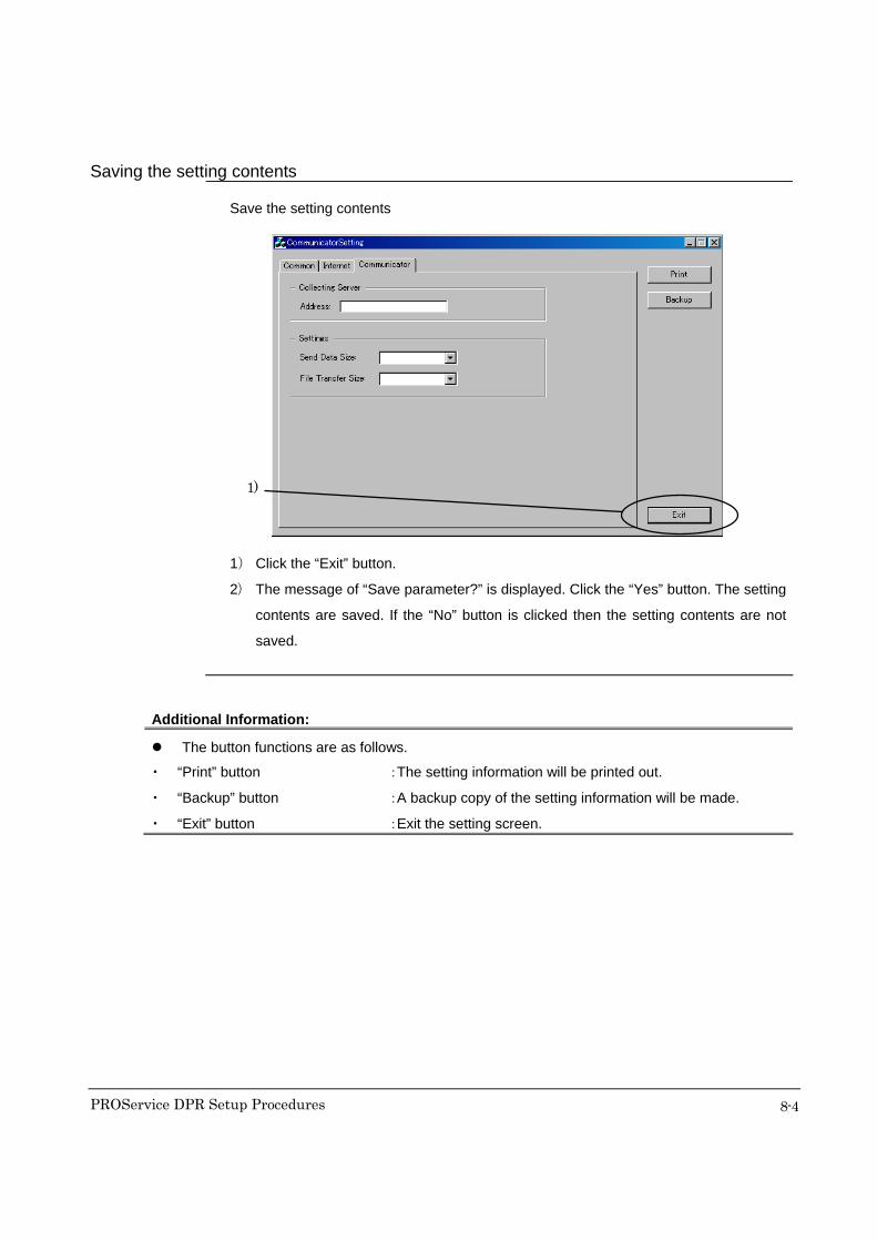
Saving the setting contents Save the setting contents
1) Click the “Exit” button.
2) The message of “Save parameter?” is displayed. Click the “Yes” button. The setting
contents are saved. If the “No” button is clicked then the setting contents are not
saved.
Additional Information:
The button functions are as follows.
・ “Print” button :The setting information will be printed out.
・ “Backup” button :A backup copy of the setting information will be made.
・ “Exit” button :Exit the setting screen.
1)

PROService DPR Setup Procedures
9-1
9 Operation Check
Check the operation using a service PC
NOTE:
Do not perform an operation check using a web browser (Internet Explorer) on the DPR. It may
cause a malfunction with the DPR or analyzer. Be sure to use a service PC for operation
checks.
Before checking the operation, connect the LAN in the facilities to the router. Immediately
disconnect the router from the LAN if a problem develops with the LAN.
Login 1) Start the analyzer with the normal procedure.
2) Start a web browser (Internet Explorer) using the service PC.
3) Connect to the PROService site.
The screen similar to the one shown below will appear.
4) Enter the login name in the [Login] edit box.
5) Enter the password in the [Password] edit box. The password will be hidden by
black dots.
4) 5) 6)

PROService DPR Setup Procedures
9-2
6) Click the “Login” button.
The screen similar to the one shown below will appear. when the login is
completed.
Additional Information:
An incorrect login name or password will cause a login failure. Re-enter the correct login name
or password.
If you fail to login because of an incorrect password three times in a row, further authentication
will be locked or stopped for security purposes. If authentication is locked, contact the
PROService system operator at the Region to ask to release the locked status. Even if you
enter the correct password, it will not be authenticated until the locked status is released.
PROService DPR Setup Procedures
9-3
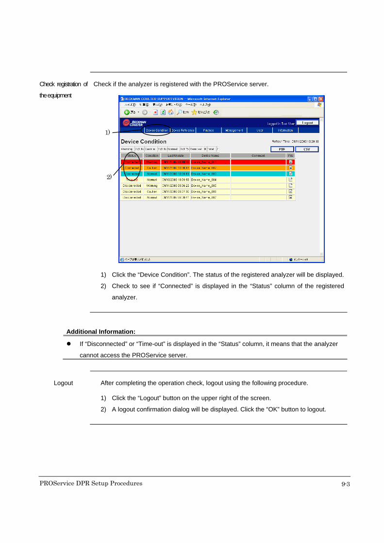
Check registration of
the equipment
Check if the analyzer is registered with the PROService server.
1) Click the “Device Condition”. The status of the registered analyzer will be displayed.
2) Check to see if “Connected” is displayed in the “Status” column of the registered
analyzer.
Additional Information:
If “Disconnected” or “Time-out” is displayed in the “Status” column, it means that the analyzer
cannot access the PROService server.
Logout After completing the operation check, logout using the following procedure.
1) Click the “Logout” button on the upper right of the screen.
2) A logout confirmation dialog will be displayed. Click the “OK” button to logout.
1)
2)
PROService DPR Setup Procedures
10-1
10 Glossary
10.1 Proxy server It is the equipment or software that exists between the internal network of a hospital or
inspection center and the Internet, which allows for connection to the Internet as a “proxy”
on behalf of computers in the internal network that do not have direct Internet connectivity.
This equipment or software is used to centralize management of access to and from the
internal network; limit connections from the internal network to specific places, and
prevent unauthorized access from outside.
The proxy must be set up to allow the PROService to be connected to our server
(PROService server) via the HTTP protocol for web browsing.
The proxy server often refers to an HTTP proxy relay. Some HTTP proxies have cache
systems to retain files recently read in order to reduce the load on connections to the
outside.
PROService DPR Setup Procedures
10-2
10.2 Type of LAN cables 10.2.1 Straight-through and crossover cables Straight-through and crossover cables are used for LAN connection. The difference
cannot be identified by appearance.
■ Straight-through cable
Signal wires inside the cable are wired straight-through and signal lines in both
end connectors are arranged the same. It is generally used to connect personal
computer to router or hub.
■ Crossover cable
Signal wires inside the cable are wired across and signal lines in both end
connectors are arranged differently. It is generally used for connection between
router and hub or hub and hub.
Additional Information:
Please use straight-through cable for connection between DPR and router.
Please use the cable specified for your site for connection between the router and LAN on site.

PROService DPR Setup Procedures
10-3
10.2.2 Solid wire and stranded wire “Solid wire” and “stranded wire” are available for signal lines inside the LAN cable. They
differ in structure of cable as shown below. Both can be used for LAN installation if they
support Category 5. However, note that difference in structure may cause failure
depending on communication speed.
Additional Information:
It is recommended that you use solid wire type cable if distance between the router and LAN is
over 15 meters and stranded wire type cable if the distance is less than 15 meters for
PROService.
10.2.3 STP and UTP Twisted pair cable for 10 Base-T is susceptible to electromagnetic noise. There are two
types of cables: STP (Shielded Twisted Pair) that shields cable for reducing noise
interference and UTP (Unshielded Twisted Pair) cable that has no shield.
Additional Information:
It is recommended to use STP cable for PROService.

PROService DPR Setup Procedures
10-4
10.2.4 Category UTP (Unshielded Twisted Pair) cable is ratified as EIA (Electronic Industries Alliance)
standard, TIA/EIA-568-A.. Cables are classified from Category 1 to Category 5 depending
on quality and they may be referred to CAT 1 to CAT 5. LAN installation uses cables with
Category 3 or higher and high-speed LAN such as 100 Base-TX requires Category 5
cable.
Category (Level) Applicable Scope Upper Limit of Transmission Speed
1 (CAT 1) - Voice (Telephone) 20 Kbps 2 (CAT 2) - ISDN basic interface
- Digital PBX - Low-speed digital terminal (such as
RS 232C)
Below 4 Mbps
3 (CAT 3) - Ethernet (10 Base-T) - Token Ring (4 Mbps)
Below 16 Mbps
4 (CAT 4) - Scope up to Category 3 - Scope up to Category - Token Ring (16 Mbps)
Below 20 Mbps
5 (CAT 5) - Scope up to Category 4 - High-speed LAN
(CDDI/100Base-T/ATM)
100 Mbps
5e (CAT 5) Enhanced Category
- Scope up to Category 5 - Gigabit communication
100 Mbps
6 (CAT 6) - Scope up to Category 5e - ATM (622 Mbps) - ATM (1.2 Gbps)
622 Mbps
* CAT 1 and CAT 2 cannot be used for PROService.
Additional Information:
It is recommended that you use Category 5 or higher cable for PROService.

PROService DPR Setup Procedures
10-5
10.2.5 Standard cable types - 10Base5
Coaxial type cable. It cannot be used for PROService.
- 10Base2
Coaxial type cable. It cannot be used for PROService.
- 10Base-T
Item Description
Cable Category 3 or higher, UTP type
Transmission Speed 10 Mbps
Maximum Distance 100 m
Maximum Network Length 500m with up to 4 segments
Topology Star wired
* The “T” of 10Base-T represents twisted pair.
- 100Base-TX
Item Description
Cable Category 5 or higher, UTP type
Transmission Speed 100 Mbps
Maximum Distance 100 m (90 m recommended)
Maximum Network Length 205 m with up to 2 segments
* Theoretically no limit for switching hub
Topology Star wired
Additional Information:
It is recommended to use 100Base-TX for PROService.
10.2.6 Other condition Some sites may require the following. Please confirm in advance.
- High burning resistance
- High bite resistance

PROService DPR Setup Procedures
11-1
11 Revision History
Date Description Version
2006.01.27 Initial Release. 1.0
2006.11.10 -3.2 Check existence of proxy server and address
Added the check of [Maximum size in which HTTP data can be transmitted in proxy].
-8.2 Setting Communicator / Setting Communicator tab menu
Added the input procedure of [Send Data Size] and [File Transfer Size].
-8.3 Setting Windows Service
Deleted the procedure of [Windows Service Setting].
2.0
2007.02.22 -3.2 Check existence of HTTP header filter and proxy server
Added the check of existence of HTTP header filter.
-3-7 Check the OSV server address
Removed this section.
-4 Preparation
Added the specification of LAN card and Router.
-8.1 Setting DPR
Corrected the explanation of "Set type 2A" at table of “Detail on setting Translated tab
menu”.
-8.2 Setting Communicator
Deleted the [Default] button.
2.1
2009.10.14 -The system name is changed to “PROService” from “OSV”.
-The Password is changed.
-8.2 Setting Communicator
“BC” is changed to “Region”.
Added to the display of “PROService Device S/N”.
2.5

■ 2. Measurement Temperature of GA unit • Standard
36.9~37.5℃ (rounded to one decimal place) • Precaution / All covers including the back panel should be mounted on the instrument while the following
measurement procedure is performed. / Leave the instrument ON at least one hour so that the internal temperature would be stabilized. • Necessary tool / Thermometer with thermistor
(it should be calibrated, and needs capability to measure 1/100℃ with accuracy) • Measurement Procedure 1) In case the cuvette wheel had been removed before measurement, wait for at least one hour
after the wheel has been back. In case the wheel cover had been removed before measurement, wait for at least fifteen minutes
after the wheel cover has been back.
2) Confirm “Bath Temp.” displayed in the System Status Screen is in range of 36.8~37.2℃. 3) Initialize the cuvette wheel by moving the instrument into STOP mode once and then back to
STANDBY mode. 4) Dispense 500µl DI water into the cuvette located at the sample dispensing hole position on the
wheel cover. 5) Insert the thermistor into the cuvette dispensed DI water. The thermistor should be located at
about 1mm higher from the bottom of the cuvette. Fix the thermistor position by putting a tape as needed.
6) Close the top cover. Thermometer main unit should be left outside the cover so that the
displayed temperature can be read. 7) Leave it around five minutes and confirm the displayed temperature is stabilized.
Then, read temperature. The top cover should be remained closed. 8) In case temperature is out of specified standard range, adjust room temperature slightly and try
measurement again. (room temperature should be 24~26℃)