Embed Size (px)
Citation preview

TABLE OF CONTENTS
SECTION TITLE PAGE
01010 GENERAL REQUIREMENTS TS-4
01300 SUBMITTALS TS-5
01500 TEMPORARY FACILITIES AND CONTROLS TS-7
02220 DEMOLITION TS-9
02300 SITE WORK, EARTHWORK AND RELATED OPERATIONS TS-10
02950 SURFACE RESTORATION TS-12
03300 CAST-IN-PLACE CONCRETE TS-13
05000 MISCELLANEOUS METALS TS-26
06100 ROUGH CARPENTRY AND WOOD CONSTRUCTION TS-27
06190 PREFABRICATED METAL PLATE CONNECTED WOOD TRUSSES TS-31
06200 FINISH CARPENTRY TS-33
06220 FIBER CEMENT SIDING TS-36
06230 FIBER CEMENT SOFFIT TS-37
07200 THERMAL INSULATION TS-38
07400 PREFORMED METAL ROOFING TS-40
07600 GENERAL SHEETMETAL TS-42
07900 CAULKING AND SEALANTS TS-46
08100 METAL DOORS AND FRAMES TS-48
08211 FLUSH WOOD DOORS TS-50
08330 OVERHEAD COILING SERVICE DOORS TS-53
08391 WATERTIGHT/RESISTANT DOORS TS-58
08500 VINYL WINDOWS TS-61
08710 HARDWARE TS-64
09200 GYPSUM WALLBOARD TS-67
09650 RESILIENT FLOORING TS-71
09700 WET LAB FLOOR/WALL SEALANT TS-74
09900 PAINTING TS-76
10800 BATHROOM ACCESSORIES & LAB EQUIPMENT TS-77
11000 HVAC EQUIPMENT TS-79
SSWDO Wildlife Health LabFile #14-014
TS-1
INTENTIONALLY LEFT BLANK
SSWDO Wildlife Health LabFile #14-014
TS-2
SECTION 01010 - GENERAL REQUIREMENTS
PART 1 – GENERAL
1.1 DESCRIPTION OF WORKA. Project includes furnishing the necessary expertise, labor, equipment, materials,
incidentals and permits required to construct a new wood-framed wildlife lab, general site improvements and appurtenances.
B. Contractor will remove from ODFW property and dispose of all spoils and debris. C. Contractor will clean area associated with project to preconstruction conditions.D. Coordinate all construction activities with on-site staff, Colin Gillin or Doug Cottam at
541-757-5242.
1.2 WORK LOCATIONA. The location of the work is 7118 NE Vandenderg Ave, Corvallis OR 97330.B. Work will be performed in a manner that does not put the staff or public in danger. Site
is in a ODFW public service office and open hours will not be limited except as required by local ordinances.
1.3 MANDATORY PRE BID CONFERENCEA. See Invitation to Bid
1.4 COMPLETION TIMEA. All work included in these specifications shall be completed by the dates in the Contract
and notice-to-proceed, unless a change order has been executed to modify the completion time.
1.5 PERMITSA. Contractor shall obtain and pay for all necessary permits associated with this work.
1.6 SUBMITTALS
A. See Section 01300
1.7 COORDINATION WITH FACILITY OPERATIONA. The contractor shall cooperate with the Owner and take all reasonable measures such
that interference by construction activities with facility operations is minimized.
1.8 WORK AND STORAGE AREAA. The contractor shall coordinate material storage area with the on-site staff.
1.9 USE OF MANUFACTURED GOODS AND PRODUCTSA. All manufactured goods and products shall essentially be the standard product of a
reputable manufacturer, appropriate to the intended use and shall be installed or applied in strict accordance with the manufacturer’s printed instructions unless specifically indicated otherwise. Copies of such instructions shall be submitted to the owner when requested.
1.10 LICENSING AND INSURANCEA. LICENSING: See Invitation to BidB. INSURANCE REQUIREMENTS: See Invitation to Bid
PART 2 - (NOT USED)
PART 3 – (NOT USED)END OF SECTION 01010
SSWDO Wildlife Health LabFile #14-014
TS-3

SECTION 01300 – SUBMITTALS
PART 1 – GENERAL
1.1 SUMMARYA. Section includes:
1. Progress Schedule2. Product Data3. Shop Drawings4. Product Samples5. Design Data6. Manufacturer’s instructions7. Reference standards
1.2 SUBMITTALSA. Progress Schedule
1. Prepare and maintain a horizontal bar chart with separate line for each subcontract and each separate area of Work, identify first day of each week, including a complete sequence of construction activity, and identification of the critical sequence of activities.
2. Indicate product submittal, purchase order, delivery, installation and site tests and inspection dates for furnished materials and equipment required for performance of the work.
3. Indicate dates for starting and finishing each phase of work.4. When updating, indicate actual and scheduled starting and finishing dates for each
separate are of Work and revise location of bar graph to indicate the revised schedule.
5. When updating identify areas of Work modified since previous submittal.6. Maintain a copy of updated progress schedule at the site.
B. Product Data1. When product data is required by a unit of work, submit manufacturer’s catalog
sheets, brochures, diagrams schedules, performance charts, illustrations and other descriptive data on manufactured products and or systems.
2. Identify data sheets with the Section and Paragraph numbers where the product or system is specified.
3. Review of product data by Project Manager is for conformance with design intent only.
C. Shop Drawings1. When shop drawings are required by a unit of work, submit showing shop assembly,
field measurements, connections, details, dimensions, finishes and fasteners.2. Cross-reference shop drawings to drawing and detail numbers in Contract
Documents.3. Review of shop drawings by Project Manager is for conformance with the design
intent only.4. For subcontract designed structural systems, submit shop drawings bearing the seal
and signature of a Structural Engineer registered for said work in the State of Oregon.D. Product Samples
1. When product samples are required by a unit of work, submit minimum of three samples of size specified/or of sufficient size to clearly illustrate characteristics of product or system.
2. Identify product samples with the Section and Paragraph numbers where the product is specified.
3. Review of product samples by Project Manager is for finish appearance and conformance with the design intent.
SSWDO Wildlife Health LabFile #14-014
TS-4
E. Design Data1. When design data is required by a unit of work, submit design drawings and
calculations for equipment and systems designed by subcontractors.2. Obtain approval of designed equipment and systems from Local Building Officials
prior to starting construction of designed equipment and systems.3. Submit design drawings and calculations bearing the seal and signature of an
engineer registered for type of work in the State of Oregon.F. Manufacturer’s Instructions
1. When products and systems are to be fabricated and installed at the site, submit manufacturer’s fabrication and installation instructions for each product and system.
G. Reference Standards1 When site fabrications and installation is specified using a referenced standard, the
installer shall have on file at the site one copy of the current standard, prior to start of site fabrication and installation.
1.3 QUANTITY OR REQUIRED SUBMITTALSA. Progress Schedules, Product Data, Shop Drawings, Design, Data, Manufacture’s
Instruction and Reference Standards:1. Submit four (2) copies of required information
B. Product Samples:1. Submit minimum of one sample, comply with each unit of work covering specific
product for size.2. When size is not specified, submit size required to clearly illustrate characteristics of
products and systems.
1.4 REVIEW SCHEDULEA. Submittals will be review by Project Manager for accuracy and completeness, if they need
further information they will be forwarded to the Engineer within three calendar days of receipt. Engineer will review and return to Project Manager within seven calendar days of receipt. Reviewed submittals will be returned to subcontractor or vendor with three working days after Engineer review.
PART 2 - (NOT USED)
PART 3 – (NOT USED)
END OF SECTION 01300
SSWDO Wildlife Health LabFile #14-014
TS-5
SECTION 01500 – TEMPORARY FACILITIES AND CONTROLS
PART 1 - GENERAL
1.1 HOURS OF WORKA. See Section 01010
1.2 PUBLIC SAFETY AND CONVENIENCEA. Contractor shall protect all obstructions within traveled roadways with approved signs,
barricades and lights where necessary or where ordered by County, City, or the Owner for the safety of the public. The convenience of the facility staff and the protection of public and property are of prime importance and shall be provided for in an adequate and satisfactory manner.
B. Whenever the Contractor's operations create a hazardous condition, Contractor shall furnish flaggers and guards as necessary to give adequate warning to the public of any dangerous condition encountered.
1.3 TRAFFIC CONTROLA. Contractor shall have responsibility for traffic control. Contractor, at its own expense,
shall be required to furnish, install and maintain all barricades, construction signs, warning signs and detour signs, as are necessary to warn and protect the public at all times from injury or damage as a result of the Contractor's operations. Contractor shall check daily the traffic control devices and reset all disturbed signs, barricades, and traffic control devices immediately. All signs and barricades necessary for nighttime traffic control shall be fully reflectorized.
1.4 CONSTRUCTION UTILITIES AND MISCELLANEOUS FACILITIESA. General: Contractor shall provide the temporary facilities and controls as hereinafter
specified and as required by law at the Contractor’s expense.B. Power: Unless otherwise specified, Contractor shall provide all necessary power and
special connections to power lines. Any power outages shall be pre-scheduled and coordinated with the Owner. The contractor shall be liable for any damages caused by unscheduled power interruptions due to its operations.
C. Water: Maintain water service to the main office for duration of the construction period.D. Sanitary facilities: The Contractor shall provide adequate toilet facilities for all workers
and Owner's representatives employed on the work. The Contractor shall maintain the same in a sanitary condition from the beginning of the work until completion and shall then remove the facilities and disinfect the premises. All portions of the work shall be maintained at all times in a sanitary condition.
E. Equipment storage: The Contractor shall be responsible for storing materials. Access to office and secure parking areas shall not be blocked except for 30 minute maximum periods in active work areas. Maintain through traffic on main roads at all times.
F. Do not store oils, solvents or equipment within 50 feet of storm drains.G. Construction signs: No commercial or advertising signs shall be allowed on the site of
the work.
1.5 EROSION CONTROLA. Contractor shall provide an approved erosion control plan in accordance to State and
Federal requirements, and shall install and maintain an erosion control system in accordance the approved plan.
1.6 FIRE PREVENTION CONTROLA. General: Take all precautions necessary and required to prevent fires. Comply with the
requirements of local authorities having jurisdiction.
SSWDO Wildlife Health LabFile #14-014
TS-6
B. Fuel for cutting and heating torches shall be gas only, and shall be contained in Underwriter's Laboratory approved containers.
C. Provide and maintain a 20-pound capacity, dry-chemical type fire extinguisher in the immediate vicinity of the work when welding tools or torches of any type are in use.
D. Do not use volatile liquids for cleaning agents or as fuels for motorized equipment or tools within building, except with the written approval of the Engineer.
1.7 POLLUTION CONTROLA. The Contractor shall not dispose of volatile fluid wastes (such as mineral spirits, oil or
paint thinner), or any other wastes which are prohibited by local ordinances, into storm or sanitary system or into stream or waterways, or on the ground.
1.8 RUBBISH REMOVALA. General:1. Clean up the debris resulting from work at least once a day and more often, if it inter -
feres with the work of others or presents a fire hazard. Pile debris where directed.2. Remove and dispose of all debris at once if it presents a fire hazard, or when directed.
1.9 DISCONTINUANCE, CHANGES AND REMOVALA. When directed and no longer required, remove the temporary facilities specified herein.
If any of the permanent systems are used for temporary facilities, restore them to pre-project condition. Material used for temporary facilities, which are removed, shall become the property of the Contractor which will be removed from the site by the Contractor.
1.10 SECURITYA. Contractor is responsible for security of his own operations at all times. B. Contractor is also responsible for the safety and security of the construction site during
non-work hours.
PART 2 - (NOT USED)
PART 3 – (NOT USED)
END OF SECTION 01500
SSWDO Wildlife Health LabFile #14-014
TS-7

SECTION 02220 - DEMOLITION
PART 1 - GENERAL
1.1 SCOPEA. The work covered by this section consists of furnishing all labor, materials, tools,
equipment and incidentals necessary to accomplish removals shown on the drawings and as specified herein.
PART 2 - (NOT USED)
PART 3 - EXECUTION
3.1 The Contractor shall call for a utility locate and shall field verify all utilities locations prior to commencing and excavation or demolition work.
3.2 Damage to any item not designated for removal shall be repaired to the Engineer's complete satisfaction at no additional cost to the State.
3.3 All materials designated for removal shall become the property of the Contractor who shall be responsible for legal disposal of the materials off the facility property.
3.4 The Contractor shall be responsible for the coordination of all removal items as they relate to the overall construction sequence.
3.5 Prior to the commencement of removal work the project manager with the Contractor will inspect the site and photographically document existing conditions for reference upon job completion.
3.6 All removal work shall be accomplished in a neat, clean and workmanlike manner taking care not to damage items or areas not scheduled for removal. Where concrete removal is required it shall be accomplished in such a manner that clean edges are left.
END OF SECTION 02220
SSWDO Wildlife Health LabFile #14-014
TS-8
SECTION 02300 - SITE WORK, EARTHWORK AND RELATED OPERATIONS
PART 1 - GENERAL
1.1 SCOPEA. The work covered by this section consists of furnishing all plant, labor, equipment, and
materials, and performing all operations to complete all excavation, fill and grading to lines shown on the drawings. All such work to be as shown on the drawings and specified herein.
1.2 GENERALA. Excavation shall include all excavation required for the building, driveways and parking
areas. Excavation shall conform to the lines shown on the drawings, and shall include the satisfactory removal and deposition of all materials encountered regardless of their nature or condition.
B. Over excavation shall be backfilled. Such backfill shall be at no additional cost to the State except when the over excavation is directed by the Engineer and is in addition to excavation designated on the drawing.
C. Final grades shall slope uniformly and shall be free of hollows which would pond rain water and shall slope to allow for surface drainage. Where practicable, no such slopes shall be flatter than 2 percent, except where specifically shown otherwise. All earthwork shall have finished surfaces which have neat, reasonably uniform appearance.
PART 2 - MATERIALS
2.1 CLASSIFICATION OF MATERIALSA. Excavation for this project is to be bid as unclassified material. No extra payment of any
kind will be allowed for the presence of water, rock, sand, peat, hardpan, logs, sandstone, boulders, old wearing surfaces, debris, or any other type of earth or foreign objects found in or near the excavation. The Contractor shall have conducted such investigations prior to the bid as deemed necessary to be properly acquainted with existing ground conditions and materials. Dewatering of the excavations shall be considered as incidental to the construction and all costs thereof shall be included in the contract price.
PART 3 - EXECUTION
3.1 CLEARING AND GRUBBINGA. It is the intent of the Owner to limit removal of trees as much as possible. Trees are to be
removed only where they interfere with facilities to be constructed. No trees are to be removed for convenience only. Care shall be taken to avoid damage to trees or roots to be saved.
B. Vegetation and stumps interfering with facilities to be constructed shall be removed. Trees shall be cut near the ground and stumps shall be rooted. Debris shall be piled in a general location designated by the Engineer for disposal by the Contractor.
3.2 PLACEMENTA. Promptly backfill excavations as work permits but not before concrete has properly cured
for at least seven days, and not before pipelines have been tested and/or accepted.B. Where existing surface levels are below planned grades or subgrade elevations or excess
excavation is performed, fill shall be provided to indicated grades or subgrade as follows; and as further specified in this subsection:
1. Beneath concrete slabs, footings or piers, or beneath designated pipe bedding, use granular fill. Beneath is defined to mean below 45 degree lines extending in both directions from the edge of the concrete or pipe bedding.
SSWDO Wildlife Health LabFile #14-014
TS-9

2. Elsewhere use native material.C. Backfill or embankment shall be placed on firm, undisturbed subgrade. No backfill or
embankment shall be placed over topsoil, roots or debris of any kind, or saturated or excessively disturbed or frozen subgrade. The Contractor shall properly dewater the subgrade and maintain it in a dewatered condition for construction operations. The Contractor's selection of equipment shall be appropriate to the subgrade conditions.
D. Backfill materials shall be placed and compacted in continuous horizontal layers. Succeeding layers shall not be placed until the preceding layer has been satisfactorily compacted.
3.3 DISPOSAL OF MATERIALSA. Excavated materials shall be placed in off-site disposal areas selected by the Contractor
and approved by the Engineer. Disposal shall be understood to mean legally disposed of, in accordance with all applicable laws, ordinances, rules and regulations.
3.4 BASE FOR FOUNDATION AND SLABSA. Material for the base course shall be ¾-inch minus crushed rock, free from wood, roots,
and other foreign materials. The material shall be well graded and shall be spread, leveled and compacted to 95% of maximum dry density.
B. Material for the sub-base shall be 1½-inch minus crushed rock, free from wood, roots, and other foreign materials. The material shall be well graded and shall be spread, leveled and compacted to 95% of maximum dry density.
C. Pipe Bedding and Pipe Zone1. Clean, 3/4-minus crushed rock with less than about 5% passing the No. 200 sieve
(washed analysis). D. Trench Backfill
1. Granular material consisting of sand and gravel or crushed rock. Maximum particle size shall be 2-inch. Use of on-site material shall be approved by the Engineer.
END OF SECTION 02300
SSWDO Wildlife Health LabFile #14-014
TS-10
SECTION 02950 - SURFACE RESTORATION
PART 1 - GENERAL
1.1 Work covered by this section includes restoration by placing top soil and seeding all cut and fill slopes and all other disturbed areas not surfaced with concrete, asphalt or gravel.
PART 2 - MATERIAL
2.1 TOPSOIL A. Topsoil shall consist of naturally occurring friable silt, sandy silt, or silty sand containing
not less than 40 percent by weight passing the No. 200 sieve. The topsoil shall be essentially free from ash, clay lumps, brush, objectionable weeds, and other litter, and shall be free from stones, stumps, roots, and other objects larger than 1 inch in diameter. The topsoil material shall be free of toxic substances and any other material that might be harmful to plant growth or be a hindrance to grading, planting, and maintenance operations. The acidity range of the topsoil shall be between pH 6.5 to 8.0, inclusively
2.2 SEED A. Seed shall be a native species currently on site and approved by the on-site staff. Seed
shall be from the most recent crop available.
2.3 MULCH A. Mulch shall be straw from bentgrass, bluegrass, fescue or ryegrass, singly or in
combination. The straw shall not be moldy, caked, decayed or of otherwise low quality.
2.4 FERTILIZER A. Fertilizer shall be 16-16-16 fertilizer.
PART 3 - EXECUTION
3.1 PLACEMENT A. Top soil shall be placed on all cut and fill slopes and other areas disturbed by
construction. Before placing the topsoil, the subgrade shall be scarified to a depth of 2 inches. Top soil shall be placed to uniform uncompacted depth of 6 inches. Top soil shall be compacted by rolling with a hand roller weighing between 25 to 100 pounds per linear foot or equivalent.
B. Fertilizer shall be applied at the rate of 20 pounds per acre.C. Seed shall be applied at the rate of 15 pounds per acre minimum.D. Mulch shall be placed within 48 hours of seeding to a loose depth of 1-1/2 to 2-1/2
inches. This rate of application will require 2 to 3 tons per acre.
3.2 MAINTENANCEA. The State will take over the maintenance of the restored areas after the surface
restoration has been completed and accepted.
END OF SECTION 02950
SSWDO Wildlife Health LabFile #14-014
TS-11
SECTION 03300 – CAST-IN-PLACE CONCRETE
PART 1 - GENERAL
1.1 This Section Includes:A. Cast-in-place concrete.B. Anchor bolts.C. Drill-in concrete anchors.
1.2 RELATED DOCUMENTSA. Drawings and general provisions of the Contract, including General and Supplemental
Conditions and Specification Section 01010, 01300, 01500, apply to this Section.
1.11 DEFINITIONSA. Cementitious Materials: Portland cement alone or in combination with one or more of
blended hydraulic cement, fly ash and other pozzolans, ground granulated blast-furnace slag, and silica fume.
1.12 SUBMITTALSA. Design Mixes: For each concrete mix. Include alternate mix designs when
characteristics of materials, project conditions, weather, test results, or other circumstances warrant adjustments.
B. Steel Reinforcement Shop Drawings: Placing drawings that detail fabrication, bending, and placement. Include bar sizes, lengths, material, grades, bar schedules, stirrup spacing, bent bar diagrams, bar arrangement, splices and laps, mechanical connections, tie spacing, hoop spacing, and supports for concrete reinforcement. Prepare in accordance with ACI Detailing Manual.
1.13 QUALITY ASSURANCEA. Installer Qualifications: An experienced installer who has completed concrete Work
similar in material, design, and extent to that indicated for this Project and whose work has resulted in construction with a record of successful in-service performance.
B. Manufacturer Qualifications: A firm experienced in manufacturing ready-mixed concrete products complying with ASTM C94 requirements for production facilities and equipment.
C. ACI Publications: Comply with the following, unless more stringent provisions are indicated:1. ACI 301, "Specification for Structural Concrete."1. ACI 117, "Specifications for Tolerances for Concrete Construction and Materials."
1.14 DELIVERY, STORAGE, AND HANDLINGA. Deliver, store, and handle steel reinforcement to prevent bending and damage.
PART 2 - PRODUCTS
2.1 FORM-FACING MATERIALSA. Smooth-Formed Finished Concrete: Form-facing panels that will provide continuous,
true, and smooth concrete surfaces. Furnish in largest practicable sizes to minimize number of joints.1. Plywood, metal, or other approved panel materials.
B. Chamfer Strips: Wood, metal, PVC, or rubber strips, ¾- by ¾-inch, minimum.
SSWDO Wildlife Health LabFile #14-014
TS-12
C. Form-Release Agent: Commercially formulated form-release agent that will not bond with, stain, or adversely affect concrete surfaces and will not impair subsequent treatments of concrete surfaces.1. Formulate form-release agent with rust inhibitor for steel form-facing materials.
D. Form Ties: Factory-fabricated, removable or snap-off metal or glass-fiber-reinforced plastic form ties or bolts designed to resist lateral pressure of fresh concrete on forms and to prevent spalling of concrete on removal.1. Furnish units that will leave no corrodible metal closer than 1-1/2 inch to the plane
of the exposed concrete surface.2. Furnish ties that, when removed, will leave holes not larger than 1 inch in diameter
in concrete surface.3. Furnish ties with integral water-barrier plates to walls in below grade or liquid
holding structure.
2.2 STEEL REINFORCEMENTA. Reinforcing Bars: ASTM A 615/A 615M, Grade 60, deformed.
2.3 REINFORCEMENT ACCESSORIESA. Bar Supports: Bolsters, chairs, spacers, and other devices for spacing, supporting, and
fastening reinforcing bars and welded wire fabric in place. Manufacture bar supports according to CRSI's "Manual of Standard Practice" from steel wire, plastic, or precast concrete or fiber-reinforced concrete of greater compressive strength than concrete, and as follows:1. Where legs of wire bar supports contact forms, use CRSI Class 1 plastic-protected
or CRSI Class 2 stainless steel bar supports.B. Tie Wire: #16 double annealed iron wire.
2.4 CONCRETE MATERIALSA. Portland Cement: ASTM C 150, Type I/II.
1. Fly Ash: ASTM C 618, Class F.B. Normal-Weight Aggregate: ASTM C 33, uniformly graded, and as follows:
1. Class: Severe weathering region, but not less than 3S.2. Nominal Maximum Aggregate Size: ¾-inch.
C. Water: Potable and complying with ASTM C 94.
2.5 ADMIXTURESA. General: Admixtures certified by manufacturer to contain no more than 0.1 percent
water-soluble chloride ions by mass of cementitious material and to be compatible with other admixtures and cementitious materials. Do not use admixtures containing calcium chloride.
B. Air-Entraining Admixture: ASTM C 260.C. Water-Reducing Admixture: ASTM C 494, Type A.D. High-Range, Water-Reducing Admixture: ASTM C 494, Type F.
2.6 CURING MATERIALSA. Evaporation Retarder: Waterborne, monomolecular film forming, manufactured for
application to fresh concrete.B. Absorptive Cover: AASHTO M 182, Class 2, burlap cloth made from jute or kenaf,
weighing approximately 9 oz./sq. yd. dry.C. Water: Potable.D. Clear, Waterborne, Membrane-Forming Curing Compound: ASTM C 309, Type 1,
Class B, 18 to 22 percent solids.E. Products: Subject to compliance with requirements, provide one of the following:
1. Evaporation Retarder:
SSWDO Wildlife Health LabFile #14-014
TS-13

a. Eucobar; Euclid Chemical Co.b. E-Con; L&M Construction Chemicals, Inc.c. Confilm; Master Builders, Inc.d. SikaFilm; Sika Corporation.
2. Clear, Waterborne, Membrane-Forming Curing Compound:a. Diamond Clear VOX; Euclid Chemical Co.b. Dress & Seal WB; L&M Construction Chemicals, Inc.c. Vocomp-20; W. R. Meadows, Inc.d. Kure-N-Seal WB; Sonneborn, Div. of ChemRex, Inc.
2.7 RELATED MATERIALSA. Joint-Filler Strips:
1. Neoprene, closed cell, expanded, ASTM D 1056, Grade No. 285, with a compression deflection of 25% for a pressure range of 17 to 24 psi.
2. Bituminous type conforming to ASTM D 1751 or sponge rubber type conforming to ASTM D 1752, Type I. For use on sidewalks and pavements. May also be used on foundation slabs below the waterstop and on backfilled walls on the backfill side of the waterstop.
3. Bond breaker tape for use in joints in walls or elevated slabs to receive joint sealants shall be an adhesive-backed glazed butyl or polyethylene tape which will satisfactorily adhere to the closed cell premolded joint material or concrete surface as required. The tape shall be the same width as the joint.
2.8 CONCRETE MIXESA. Prepare design mixes for each type and strength of concrete determined by either
laboratory trial mix or field test data bases, as follows:1. Proportion normal-weight concrete according to ACI 211.1 and ACI 301.
B. Use a qualified independent testing agency for preparing and reporting proposed mix designs for the laboratory trial mix basis.
C. Class A: All concrete unless noted otherwise. Proportion normal-weight concrete mix as follows:1. Compressive Strength (28 Days): 3500 psi.2. Maximum Slump: 4 inches.3. Maximum Slump for Concrete Containing High-Range Water-Reducing Admixture:
8 inches after admixture is added to concrete with 2- to 4-inch slump.D. Cementitious Materials: For concrete exposed to deicers, limit percentage, by weight,
of cementitious materials other than portland cement according to ACI 301 requirements.
E. Cementitious Materials: Limit percentage, by weight, of cementitious materials other than portland cement in concrete as follows:1. Fly Ash
a. Class A Concrete: 0 to 25 percent.F. Maximum Water-Cementitious Materials Ratio:
1. Class A Concrete: 0.45.G. Air Content: Add air-entraining admixture at manufacturer's prescribed rate to result in
concrete at point of placement having an air content as follows within a tolerance of plus 1 or minus 1.5 percent, unless otherwise indicated:1. Air Content: 6 percent for 3/4-inch- nominal maximum aggregate size.
H. Limit water-soluble, chloride-ion content in hardened concrete to 0.15 percent by weight of cement.
I. Admixtures: Use admixtures according to manufacturer's written instructions.1. Use water-reducing admixture or high-range water-reducing admixture
(superplasticizer) in concrete, as required, for placement and workability.
SSWDO Wildlife Health LabFile #14-014
TS-14

2. Use water-reducing and retarding admixture when required by high temperatures, low humidity, or other adverse placement conditions.
3. Use water-reducing admixture in pumped concrete, concrete for heavy-use industrial slabs and parking structure slabs, concrete required to be watertight, and concrete with a water-cementitious materials ratio below 0.50.
2.9 FABRICATING REINFORCEMENTA. Fabricate steel reinforcement according to CRSI's "Manual of Standard Practice."
2.10 CONCRETE MIXINGA. Ready-Mixed Concrete: Measure, batch, mix, and deliver concrete according to
ASTM C 94, and furnish batch ticket information.
2.11 GROUTA. Drypack Grout: Drypack grout shall be a mixture of approximately one part cement, 1-
1/2 to 2 parts sand, water reducing agent, and sufficient water to make a stiff workable mix.
B. Cement Grout: Cement grout shall be a mixture of one part cement, two parts sand, proportioned by volume, admixtures for pressure grouting, and sufficient water to form a workable mix.
C. Nonshrink Grout: Nonshrink grout shall be ASTM C 1107, Type B or C non-metallic aggregate grout with a minimum compressive strength of 7,000 psi in 28 days.
2.12 EMBEDDED ITEMSA. Inserts shall be as required by other trades. Attach securely to forms. Inserts within
reinforcement cover thickness shall be hot-dip galvanized, nonferrous or other approved nonrusting material.
B. Miscellaneous embedded item: Exposed items permanently embedded in concrete with concrete reinforcement thickness shall be hot-dip galvanized, nonferrous or plastic as approved, to eliminate the possibility of stained or rusty spots.
2.13 ANCHOR BOLTS AND CONCRETE ANCHORSA. General:
1. This section covers the work necessary to furnish, install and complete all anchorage to concrete, complete with washers and nuts.
2. Like items of materials provided hereunder shall be the end products of one manufacturer in order to achieve standardization for appearance, maintenance, and replacement.
3. The diameter and projection shall be as required by the equipment or machinery manufacturer. The Contractor shall verify the capacities and configurations conform to the Drawings.
4. Submittals: Comply with requirements of Section 01300 Submittal Procedures. In addition, the following specific information shall be provided:a. ICBO (International Conference of Building Officials) reports verifying the
products meet or exceed the capacities shown on the Drawings. Manufacturers’ information showing the recommended installation equipment and procedures for the following:1) Drilled in concrete anchors.2) Epoxy anchor adhesive.
5. Exposure Conditions: Exposure conditions shall be defined as follows:a. Dry: Indoor areas not subject to moisture, wash down, or chemicals.b. Wet: Indoor areas subject to moisture, wash-down, or chemicals, or outdoor
areas.c. Submerged: At or below a point 1 foot 6 inches above maximum fluid surface.
SSWDO Wildlife Health LabFile #14-014
TS-15

6. Unless otherwise indicated, all materials shall conform to the latest issue of the following ASTM Specifications:a. Anchor Bolts:
1) Carbon Steel: ASTM A 307, Grade A 36.2) Stainless: ASTM F 593, Type 316, Grade CW1 or SH2.
b. Galvanized Steel Bolts: ASTM A 153, zinc coating for ASTM A 307 or A 36.c. Flat Washers (Unhardened): ASTM F 844, use ASTM A 153 for zinc coating.d. Threaded Bars: ASTM A 36.e. Drilled-In Concrete Anchors:
1) Carbon Steel Anchors: ASTM A 108.2) Stainless Steel: ASTM F 593, Type 316, Grade CW1 or SH2.
f. Epoxy Anchors:1) Stainless-Steel Anchors: ASTM F 593, Type 316.2) Epoxy Adhesive: ASTM C 881, Type 1, Grade 3, Class A, B, or C.
g. Nuts:1) Carbon Steel: ASTM A 307.2) Stainless Steel: ASTM F 593, Type 316.
h. Galvanizing:1) Carbon Steel: ASTM A 153, Zinc Coating for ASTM A 307.
7. The concrete anchorage system indicated on the Drawings, or required to secure the various parts together and provide a complete installation, shall be included under this section. The tabulation of items herein is not intended to be all-inclusive, and it shall be the Contractor’s responsibility to provide all metalwork and castings shown, specified, or which can reasonably be inferred as necessary to complete the project.
B. Anchor Bolts1. Unless shown otherwise on the Drawings, use 5/8-inch minimum diameter by 12-
inch long and other geometry shown on the Drawings. Furnish a minimum of two nuts and a washer of the same material for each bolt. Provide sleeves as shown on the Drawings for location adjustment.
2. Provide anchor bolt material for the exposure conditions as noted below:a. Fabricated Metalwork or Structural Building or Frame Components:
1) Dry Exposure, use galvanized steel.2) Wet exposure, use stainless steel.
C. Concrete Expansion Anchors: Drilled-in concrete anchors shall be Trubolt Wedge anchors manufactured by ITW Ramset/Red Head; Kwik-Bolt II stud type anchors, manufactured by Hilti, Inc., or Power-stud anchors by Powers Rawl. Anchors shall have allowable working loads not less than those tabulated in the Structural General Notes. Provide diameter shown or required except minimum diameter of 1/2 inch.
D. Adhesive Threaded Rod Anchors: ASTM A-36 or 316 stainless steel threaded rod free of grease, oil, or other deleterious material.1. Products: Covert Operations CIA-GEL 7000, Hilti HY150, of U.S. Anchor, HS 200
Epoxy Resin or approved equal.2. Anchors shall have allowable working loads not less than those tabulated in the
Structural General Notes. Provide minimum diameter of 1/2 inch.3. Provide concrete anchors for the exposure conditions as noted below:
a. Drilled-In Concrete Anchors:1) Dry exposure, use galvanized steel.2) Wet exposure, use stainless steel.3) Submerged exposure, do not use.
b. Adhesive Anchors:1) Dry exposure, use galvanized steel.2) Wet exposure, use stainless steel.3) Submerged exposure, use stainless steel.
SSWDO Wildlife Health LabFile #14-014
TS-16

4) Adhesive anchors shall not be used in any overhead applications.4. Drilled-in concrete anchors shall not be used for anchoring of any machinery or
equipment with moving parts.E. Stainless-Steel Fasteners Lubricant (Anti-Seizing)
1. Where stainless steel nuts and machined bolts, anchor bolts, concrete anchors, and all other threaded fasteners are used, Contractor shall apply an anti-seizing lubricant to the threads prior to making up the connections. The lubricant shall contain substantial amounts of molybdenum disulfide, graphite, mica, talc, or copper.
PART 3 - EXECUTION
3.1 FORMWORKA. Design, erect, shore, brace, and maintain formwork, according to ACI 301, to support
vertical, lateral, static, and dynamic loads, and construction loads that might be applied, until concrete structure can support such loads.
B. Construct formwork so concrete members and structures are of size, shape, alignment, elevation, and position indicated, within tolerance limits of ACI 117.
C. Limit concrete surface irregularities, designated by ACI 347R as abrupt or gradual, as follows:1. Class B, 1/4 inch.
D. Construct forms tight enough to prevent loss of concrete mortar.E. Fabricate forms for easy removal without hammering or prying against concrete
surfaces. Provide crush or wrecking plates where stripping may damage cast concrete surfaces. Provide top forms for inclined surfaces steeper than 1.5 horizontal to 1 vertical. Kerf wood inserts for forming keyways, reglets, recesses, and the like, for easy removal.1. Do not use rust-stained steel form-facing material.
F. Set edge forms, bulkheads, and intermediate screed strips for slabs to achieve required elevations and slopes in finished concrete surfaces. Provide and secure units to support screed strips; use strike-off templates or compacting-type screeds.
G. Provide temporary openings for cleanouts and inspection ports where interior area of formwork is inaccessible. Close openings with panels tightly fitted to forms and securely braced to prevent loss of concrete mortar. Locate temporary openings in forms at inconspicuous locations.
H. Chamfer exterior corners and edges of permanently exposed concrete.I. Form openings, chases, offsets, sinkages, keyways, reglets, blocking, screeds, and
bulkheads required in the Work. Determine sizes and locations from trades providing such items.
J. Clean forms and adjacent surfaces to receive concrete. Remove chips, wood, sawdust, dirt, and other debris just before placing concrete.
K. Retighten forms and bracing before placing concrete, as required, to prevent mortar leaks and maintain proper alignment.
L. Coat contact surfaces of forms with form-release agent, according to manufacturer's written instructions, before placing reinforcement.
3.2 EMBEDDED ITEMSA. Place and secure anchorage devices and other embedded items required for adjoining
work that is attached to or supported by cast-in-place concrete. Use Setting Drawings, templates, diagrams, instructions, and directions furnished with items to be embedded.1. Position in form in location shown. Do not place concrete before receiving
approval of placing plan by Building Inspector.2. Provide adequate support to prevent displacement during concreting.
SSWDO Wildlife Health LabFile #14-014
TS-17

3. Allow other trades ample time and facilities for placing and installing embedded items.
3.3 REMOVING AND REUSING FORMSA. General: Formwork, for sides of beams, walls, columns, and similar parts of the Work,
that does not support weight of concrete may be removed after cumulatively curing at not less than 50 deg F for 24 hours after placing concrete provided concrete is hard enough to not be damaged by form-removal operations and provided curing and protection operations are maintained.
B. Leave formwork, for beam soffits, joists, slabs, and other structural elements, that supports weight of concrete in place until concrete has achieved the following:1. At least 70 percent of 28-day design compressive strength.2. Determine compressive strength of in-place concrete by testing representative
field- or laboratory-cured test specimens according to ACI 301.3. Remove forms only if shores have been arranged to permit removal of forms
without loosening or disturbing shores.C. Clean and repair surfaces of forms to be reused in the Work. Split, frayed, delaminated,
or otherwise damaged form-facing material will not be acceptable for exposed surfaces. Apply new form-release agent.
D. When forms are reused, clean surfaces, remove fins and laitance, and tighten to close joints. Align and secure joints to avoid offsets. Do not use patched forms for exposed concrete surfaces unless approved by the Engineer.
3.4 STEEL REINFORCEMENTA. General: Comply with CRSI's "Manual of Standard Practice" for placing reinforcement.
Bends are per ACI 318, Section 7.1 and 7.2.B. Clean reinforcement of loose rust and mill scale, earth, ice, and other foreign materials.C. Accurately position, support, and secure reinforcement against displacement. Locate
and support reinforcement with bar supports to maintain minimum concrete cover. Do not tack weld crossing reinforcing bars.
D. Set wire ties with ends directed into concrete, not toward exposed concrete surfaces.E. Fabrication
1. Clean, bend and splice reinforcement in accordance with Uniform Building Code and ACI 315. Hooks shall conform to Table 1 of ACI 315. Do not straighten or rebend Grade 60 reinforcement. All bars shall be bent cold. Welding shall be performed by welders certified by American Welding Society and in accordance with AWS D1.1 and only on weldable grade rebar
F. Bending Schedules1. Placement drawings and bending schedules shall be submitted to the Engineer for
review. Reinforcement shall be formed as indicated on the Drawings. Except where specifically indicated otherwise on the Drawings, ends for bars shall be in accordance with the requirements of ACI 318, Section 7.1 and 7.2.
G. Placing Reinforcing Steel1. Reinforcing steel, before being positioned, shall be cleaned of mill scale, rust or
other coatings that will destroy or reduce the bond. Reinforcement appreciably reduced in section shall be rejected. Prior to placing concrete, the reinforcement shall be reinspected by the Engineer and, when necessary, cleaned to the satisfaction of the Engineer.a. Reinforcing steel shall not be bent or straightened without the approval of the
Engineer, nor in a manner that will injure the material. Bars with kinks or bends not shown on the Drawings shall not be used. Heating or welding of bars will be permitted only when the entire operation is acceptable to the Engineer.
SSWDO Wildlife Health LabFile #14-014
TS-18
b. Reinforcing steel shall be positioned accurately and secured against displacement by using annealed iron wire or suitable clips at intersections and shall be supported by concrete or metal chairs or spacers, or metal hangers.
c. In walls, splices of reinforcement shall not be permitted. d. The clear distance between parallel bars shall not be less than the diameter
of the bars and, unless specifically authorized, shall in no case be less than 1-inch nor less than the maximum size of coarse aggregate specified. When reinforcement in beams is placed in two or more layers, the clear distance between layers shall not be less than 1-inch, and the bars in the upper layers shall be placed directly above those in the bottom layer.
e. Concrete protection for reinforcement: Unless stated otherwise on the Drawings, reinforcement shall have a minimum cover of the following:1) Cast against and permanently exposed to earth: 3 inches2) Concrete to be in contact with sewage: 2 inches1) Concrete to be in contact with ground, weather or clean water:
a) No. 6 bars and larger: 2 inchesb) No. 5 bars and smaller and welded wire fabric: 2 inches
3) Concrete not to be exposed to ground, weather or water:a) Slabs and walls: 1-inchb) Beams and columns: 1-1/2 inchesc) Joists: 3/4-inch
H. Tolerances1. Fabricating and placing tolerances shall be in accordance with ACI 301.
3.5 CONCRETE PLACEMENTA. Before placing concrete, verify that installation of formwork, reinforcement, and
embedded items is complete and that required inspections have been performed. Placement shall be per ACI 301 unless noted otherwise.
B. Do not add water to concrete during delivery, at Project site, or during placement, unless approved by the Engineer.1. Do not add water to concrete after adding high-range water-reducing admixtures to
mix.C. Deposit concrete continuously or in layers of such thickness that no new concrete will
be placed on concrete that has hardened enough to cause seams or planes of weakness. If a section cannot be placed continuously, provide construction joints as specified. Deposit concrete to avoid segregation.
D. Deposit concrete in forms in horizontal layers no deeper than 24 inches and in a manner to avoid inclined construction joints. Place each layer while preceding layer is still plastic, to avoid cold joints.1. Consolidate placed concrete with mechanical vibrating equipment. Use equipment
and procedures for consolidating concrete recommended by ACI 309R.2. Do not use vibrators to transport concrete inside forms. Insert and withdraw
vibrators vertically at uniformly spaced locations no farther than the visible effectiveness of the vibrator. Place vibrators to rapidly penetrate placed layer and at least 6 inches into preceding layer. Do not insert vibrators into lower layers of concrete that have begun to lose plasticity. At each insertion, limit duration of vibration to time necessary to consolidate concrete and complete embedment of reinforcement and other embedded items without causing mix constituents to segregate.
E. Deposit and consolidate concrete for floors and slabs in a continuous operation, within limits of construction joints, until placement of a panel or section is complete.1. Consolidate concrete during placement operations so concrete is thoroughly
worked around reinforcement and other embedded items and into corners.2. Maintain reinforcement in position on chairs during concrete placement.
SSWDO Wildlife Health LabFile #14-014
TS-19

3. Screed slab surfaces with a straightedge and strike off to correct elevations.4. Slope surfaces uniformly to drains where required.5. Begin initial floating using bull floats or darbies to form a uniform and open-textured
surface plane, free of humps or hollows, before excess moisture or bleed water appears on the surface. Do not further disturb slab surfaces before starting finishing operations.
F. Cold-Weather Placement: Comply with ACI 306.1 and as follows. Protect concrete work from physical damage or reduced strength that could be caused by frost, freezing actions, or low temperatures.1. When air temperature has fallen to or is expected to fall below 40 degrees F,
uniformly heat water and aggregates before mixing to obtain a concrete mixture temperature of not less than 50 degrees F and not more than 80 degrees F at point of placement.
2. Do not use frozen materials or materials containing ice or snow. Do not place concrete on frozen subgrade or on subgrade containing frozen materials.
3. Do not use calcium chloride, salt, or other materials containing antifreeze agents or chemical accelerators, unless otherwise specified and approved in mix designs.
G. Hot-Weather Placement: Place concrete according to recommendations in ACI 305R and as follows, when hot-weather conditions exist:1. Cool ingredients before mixing to maintain concrete temperature below 90
degrees F at time of placement. Chilled mixing water or chopped ice may be used to control temperature, provided water equivalent of ice is calculated to total amount of mixing water. Using liquid nitrogen to cool concrete is Contractor's option.
2. Cover steel reinforcement with water-soaked burlap so steel temperature will not exceed ambient air temperature immediately before embedding in concrete.
3. Fog-spray forms, steel reinforcement, and subgrade just before placing concrete. Keep subgrade moisture uniform without standing water, soft spots, or dry areas.
3.6 FINISHING FORMED SURFACESA. Rough-Formed Finish: As-cast concrete texture imparted by form-facing material with
tie holes and defective areas repaired and patched. Remove fins and other projections exceeding ACI 347R limits for class of surface specified. Use rough-formed finish where concrete is not exposed to view or in contact with waterproof membrane or PVC liner.1. Apply to surfaces not indicated on the Drawings or in this section to achieve a
smooth formed finish.B. Smooth-Formed Finish: As-cast concrete texture imparted by form-facing material,
arranged in an orderly and symmetrical manner with a minimum of seams. Repair and patch tie holes and defective areas. Remove fins and other projections exceeding 1/8 inch in height.1. Apply to concrete surfaces exposed to view, contact with water or sewage or to be
covered with a coating or covering material applied directly to concrete, such as waterproofing, damp proofing, veneer plaster, or painting.
C. Rubbed Finish: Apply the following to smooth-formed finished concrete except for surfaces receiving waterproofing or PVC liner.
D. Select one rubbed finish from subparagraphs below if required.1. Smooth-Rubbed Finish: Not later than one day after form removal, moisten
concrete surfaces and rub with carborundum brick or another abrasive until producing a uniform color and texture. Do not apply cement grout other than that created by the rubbing process.
E. Related Unformed Surfaces: At tops of walls, horizontal offsets, and similar unformed surfaces adjacent to formed surfaces, strike off smooth and finish with a texture
SSWDO Wildlife Health LabFile #14-014
TS-20
matching adjacent formed surfaces. Continue final surface treatment of formed surfaces uniformly across adjacent unformed surfaces, unless otherwise indicated.
3.7 FINISHING FLOORS AND SLABSA. General: Comply with recommendations in ACI 302.1R for screeding, restraightening,
and finishing operations for concrete surfaces. Do not wet concrete surfaces.B. Scratch Finish: While still plastic, texture concrete surface that has been screeded and
bull-floated or darbied. Use stiff brushes, brooms, or rakes.1. Apply scratch finish to surfaces indicated and to surfaces to receive concrete floor
topping or mortar setting beds for ceramic or quarry tile, portland cement terrazzo, and other bonded cementitious floor finishes.
C. Float Finish: Consolidate surface with power-driven floats or by hand floating if area is small or inaccessible to power driven floats. Restraighten, cut down high spots, and fill low spots. Repeat float passes and restraightening until surface is left with a uniform, smooth, granular texture.1. Apply float finish to surfaces indicated, to surfaces to receive trowel finish, and to
floor and slab surfaces to be covered with fluid-applied or sheet waterproofing, built-up or membrane roofing, or sand-bed terrazzo.
D. Trowel Finish: After applying float finish, apply first trowel finish and consolidate concrete by hand or power-driven trowel. Continue troweling passes and restraighten until surface is free of trowel marks and uniform in texture and appearance. Grind smooth any surface defects that would telegraph through applied coatings or floor coverings.1. Apply a trowel finish to surfaces indicated and to floor and slab surfaces exposed
to view, in contact with liquids or to be covered with resilient flooring, carpet, ceramic or quarry tile set over a cleavage membrane, paint, or another thin film-finish coating system and to slabs in structures containing water, sewage or other liquids.
2. Finish and measure surface so gap at any point between concrete surface and an unleveled freestanding 10-foot- long straightedge, resting on two high spots and placed anywhere on the surface, does not exceed the following:a. 3/16 inch.
E. Trowel and Fine-Broom Finish:, Apply a trowel and fine-broom finish to exterior concrete platforms, steps, and ramps, surfaces where ceramic or quarry tile is to be installed by either thickset or thin-set method, and elsewhere as indicated 1. Apply a partial trowel finish. Immediately after second troweling, and when
concrete is still plastic, slightly scarify surface with a fine broom. Coordinate required final finish with Owner’s Representative before application.
3.8 MISCELLANEOUS CONCRETE ITEMSA. Filling In: Fill in holes and openings left in concrete structures, unless otherwise
indicated, after work of other trades is in place. Mix, place, and cure concrete, as specified, to blend with in-place construction. Provide other miscellaneous concrete filling indicated or required to complete Work.
B. Anchor Bolts and Concrete Anchors: Install per manufacturer’s recommendations. Cutting and welding shall not be permitted. Protect dissimilar metals in conformance to Section 05000, Miscellaneous Metals. Items to be embedded in concrete shall be placed accurately and held securely during placement. Anchors shall be protected after installation by coating the exposed threads with lubricant (anti-seizing) and installing the nut.1. Anchor Bolts: All anchor bolts shall be accurately located and held in place with
templates at the time the concrete is poured.2. Concrete Anchors: Installation shall not begin until the concrete or masonry
receiving the anchors has attained its design strength. Install in strict conformance
SSWDO Wildlife Health LabFile #14-014
TS-21

with manufacturer’s written instructions. Use manufacturer’s recommended drills and equipment.a. Adhesive Anchors: Do not install when temperature of concrete is below 35
degrees F or above 110 degrees F.b. Furnish manufacturer’s representative, for each type of concrete anchor
used, to the jobsite to conduct jobsite training for proper installation, handling, and storage of each anchor system for personnel as required. Notify the Engineer of training session schedule.
c. Flush mounted concrete anchors shall not be used unless specifically shown on the Drawings or approved by the Project Manager.
3. Galvanizing and Repair:a. The minimum pitch diameter of the threaded portion of all bolts, anchor bars,
or studs shall conform to ANSI B1.1, having a Class 2A tolerance before galvanizing. After galvanizing, the pitch diameter of the nuts or other internally threaded parts may be tapped over ANSI B1.1, Class 2B tolerance by the following maximum amounts:
3/8-inch through 9/16-inch 0.016-inch oversize5/8-inch through 1-inch 0.023-inch oversize1-1/8-inch and larger 0.033-inch oversize
b. Galvanized surfaces that are abraded or damaged at any time after the application of the zinc coating shall be repaired by solvent cleaning the damaged area (Steel Structures Painting Council SP 2 or SP 3) the damaged areas, removing all loose and cracked coating, after which the cleaned areas shall be painted as specified in Section 09900, Painting.
3.9 CONCRETE PROTECTION AND CURINGA. General: Protect freshly placed concrete from premature drying and excessive cold or
hot temperatures. Comply with ACI 306.1 for cold-weather protection and with recommendations in ACI 305R for hot-weather protection during curing.
B. Evaporation Retarder: Apply evaporation retarder to unformed concrete surfaces if hot, dry, or windy conditions cause moisture loss approaching 0.2 lb/sq. ft. x h before and during finishing operations. Apply according to manufacturer's written instructions after placing, screeding, and bull floating or darbying concrete, but before float finishing.
C. Formed Surfaces: Cure formed concrete surfaces, including underside of beams, supported slabs, and other similar surfaces. Forms shall be covered and kept moist. The forms shall be loosened, as soon as possible without damage to the concrete, and provisions made for curing water to run down inside them. During form removal, care shall be taken to provide wet cover to newly exposed surfaces. If removing forms before end of curing period, continue curing by one or a combination of the methods indicated below.
D. Unformed Surfaces: Begin curing immediately after finishing concrete. Cure unformed surfaces, including floors and slabs, concrete floor toppings, and other surfaces, by one or a combination of the methods indicated below.
E. Curing Methods:1. Moisture Curing: Moisture cure all surfaces of all liquid holding structures. Keep
surfaces continuously moist for not less than seven days with the following materials:a. Water.b. Continuous water-fog spray.c. Absorptive cover, water saturated, and kept continuously wet. Cover
concrete surfaces and edges with 12-inch lap over adjacent absorptive covers.2. Moisture-Retaining-Cover Curing: Cover concrete surfaces with moisture-retaining
cover for curing concrete, placed in widest practicable width, with sides and ends
SSWDO Wildlife Health LabFile #14-014
TS-22
lapped at least 12 inches, and sealed by waterproof tape or adhesive. Cure for not less than seven days. Immediately repair any holes or tears during curing period using cover material and waterproof tape.a. Moisture cure or use moisture-retaining covers to cure concrete surfaces to
receive floor coverings.b. Moisture cure or use moisture-retaining covers to cure concrete surfaces to
receive penetrating liquid floor treatments.c. Cure concrete surfaces to receive floor coverings with either a moisture-
retaining cover or a curing compound that the manufacturer recommends for use with floor coverings.
3. Curing Compound: Apply uniformly in continuous operation by power spray or roller according to manufacturer's written instructions. Recoat areas subjected to heavy rainfall within three hours after initial application. Maintain continuity of coating and repair damage during curing period.
3.10 CONCRETE SURFACE REPAIRSA. Defective Concrete: Repair and patch defective areas when approved by the Engineer.
Remove and replace concrete that cannot be repaired and patched to Engineer's approval.
B. Repairing Formed Surfaces: Surface defects include color and texture irregularities, cracks, spalls, air bubbles, honeycombs, rock pockets, fins and other projections on the surface, and stains and other discolorations that cannot be removed by cleaning.1. Immediately after form removal, cut out honeycombs, rock pockets, and voids more
than 1/2 inch in any dimension in solid concrete. Make edges of cuts perpendicular to concrete surface. Clean, dampen with water, and brush-coat holes and voids with bonding agent. Fill and compact with drypack grout before bonding agent has dried. Fill form-tie voids with patching mortar or cone plugs secured in place with bonding agent.
2. Repair defects on surfaces exposed to view by blending white portland cement and standard portland cement so that, when dry, drypack grout will match surrounding color. Patch a test area at inconspicuous locations to verify mixture and color match before proceeding with patching. Compact mortar in place and strike off slightly higher than surrounding surface.
3. Repair defects on concealed, formed surfaces that affect concrete's durability and structural performance as determined by the Engineer.
C. Repairing Unformed Surfaces: Test unformed surfaces, such as floors and slabs, for finish and verify surface tolerances specified for each surface. Correct low and high areas. Test surfaces sloped to drain for trueness of slope and smoothness; use a sloped template.1. Repair finished surfaces containing defects. Surface defects include spalls,
popouts, honeycombs, rock pockets, crazing and cracks in excess of 0.01 inch wide or that penetrate to reinforcement or completely through unreinforced sections regardless of width, and other objectionable conditions.
2. After concrete has cured at least 14 days, correct high areas by grinding.3. Correct localized low areas during or immediately after completing surface finishing
operations by cutting out low areas and replacing with patching mortar. Finish repaired areas to blend into adjacent concrete.
4. Correct other low areas scheduled to receive floor coverings with a repair underlayment. Prepare, mix, and apply repair underlayment and primer according to manufacturer's written instructions to produce a smooth, uniform, plane, and level surface. Feather edges to match adjacent floor elevations.
5. Repair defective areas, except random cracks and single holes 1 inch or less in diameter, by cutting out and replacing with fresh concrete. Remove defective areas with clean, square cuts and expose steel reinforcement with at least ¾-inch
SSWDO Wildlife Health LabFile #14-014
TS-23
clearance all around. Dampen concrete surfaces in contact with patching concrete and apply bonding agent. Mix patching concrete of same materials and mix as original concrete except without coarse aggregate. Place, compact, and finish to blend with adjacent finished concrete. Cure in same manner as adjacent concrete.
6. Repair random cracks and single holes 1 inch or less in diameter with drypack grout. Groove top of cracks and cut out holes to sound concrete and clean off dust, dirt, and loose particles. Dampen cleaned concrete surfaces and apply bonding agent. Place drypack grout before bonding agent has dried. Compact and finish to match adjacent concrete. Keep patched area continuously moist for at least 72 hours.
D. Perform structural repairs of concrete, subject to Engineer's approval, using epoxy adhesive and drypack grout.
E. Repair materials and installation not specified above may be used, subject to Engineer's approval.
3.11 GROUTA. General
1. Bonding compound for use with grout is specified. Primer, if required for polymer concrete, shall be provided per manufacturer's recommendation.
2. Grout shall not be placed during freezing weather unless adequate protection is provided.
B. Drypack Grout1. Drypack grout shall be used for built-up surfaces, setting miscellaneous metal
items and minor repairs.2. Surfaces required to be built up with drypack grout shall be roughened by brushing,
cleaned, and coated with the bonding compound before the application of the grout. The drypack grout shall be applied immediately following the application of the bonding compound in bands or strips to form a covering of the required thickness. The covering shall be smooth. Construction joints in the grout shall be sloped and shall be cleaned and wetted before application is resumed.
3. Drypack grout shall be cured in accordance with Section 03300.C. Cement Grout
1. Cement grout shall be used for filling nonbearing portions of equipment pads and pressure grouting.
2. Except for the specialized equipment for pressure grouting, mixing and placing apparatus shall be similar to that normally used for cast-in-place concrete. Grout shall be mixed for a period of at least 1 minute. Diluted grout shall be agitated to keep ingredients mixed.
D. Nonshrink Grout1. Nonshrink grout shall be used for the bearing surfaces of machinery and
equipment bases, column base plates, bearing plates, and for setting anchor bolts and reinforcing steel in holes. Grout shall be placed in accordance with manufacturer's instructions.
2. Holes required for grouting shall be blown clean with compressed air and left free of dust or standing water. Horizontal holes for grouting shall be drilled at a slight downward angle to facilitate holding the grout until setting is complete. Bolts or reinforcing steel installed in horizontal grout holes shall be bent slightly accordingly.
E. Epoxy Grout1. Epoxy grout shall be used for repairing cracks by pressure grouting or gravity flow,
repairing structural concrete, and may be used for setting reinforcing dowels or anchor bolts into holes for grouting. Concrete shall be primed in accordance with the grout manufacturer's instructions.
2. Use of epoxy grout for anchorage of bolts or reinforcing dowels shall be subject to the following conditions:
SSWDO Wildlife Health LabFile #14-014
TS-24
a. Use shall be limited to locations where exposure, on an intermittent or continuous basis, to acid concentrations higher than 10%, to chlorine gas, or to machine or diesel oils, is extremely unlikely.
b. Use shall be limited to applications where exposure to fire or exposure to concrete or rod temperature above the product's heat deflection temperature or 120 degrees F (whichever is less) is extremely unlikely. Overhead applications (such as pipe supports) because of the above concerns, are not allowed.
c. Approval from Engineer for specific application and from supplier of equipment to be anchored, if applicable.
d. Anchor diameter and grade of steel shall be per contract documents or per equipment supplier specifications. Anchor shall be threaded or deformed full length of embedment and shall be free of rust, scale, grease, and oils.
e. Embedment depth and hole diameter shall be as specified.f. Holes shall have rough surfaces, such as can be achieved using a rotary
percussion drill.g. Holes shall be blown clean with compressed air and be free of dust or standing
water prior to application of grout.h. Anchor shall be left undisturbed and unloaded for full curing period.i. Anchors shall not be placed in concrete below 25 degrees F.
END OF SECTION 03300
SSWDO Wildlife Health LabFile #14-014
TS-25
SECTION 05000 - MISCELLANEOUS METALS
PART 1 - GENERAL
1.1 SUMMARYA. Work covered by this section includes structural steel materials, fabrication and erection.
1.2 REFERENCED SPECIFICATIONA. Conform to latest edition, AISC specification for the design, fabrication and erection of
structural steel for buildings.
1.3 SUBMITTALSA. Submit four (2) sets of shop drawings to Engineer. Shop drawings shall be submitted for
the engineer's approval prior to fabrication, and shall show all details and accessory items. All shop drawing detailing shall comply with applicable requirements of "AISC Specification For The Design, Fabrication, And Erection Of Structural Steel For Buildings." shop drawings shall fully designate protective coatings and fully designate all shop and field welds and electrodes to be used in welding. No field welds or field burning will be allowed unless shown on approved shop drawings, or approved by the Engineer.
PART 2 - PRODUCTS
2.1 QUALITYA. All materials shall be free of defects impairing strength, durability and appearance, true to
detail, with sharply defined profiles. Materials shall conform to the following, except as otherwise specified or unless shown otherwise on the drawings. Fabricated metalwork not otherwise designated or specified shall be carbon steel.
2.2 MATERIALSA. Shapes, Plates – ASTM A36 Fy 36 KSI.B. Steel Pipe - ASTM A-53 Grade B. Pipe shall be STANDARD weight.C. Threaded Rod – AISI 304 stainless steelD. Epoxy Anchor – HILTI HY 150 epoxy, or equalE. Anchor Bolts – ASTM A307 OR ASTM A36.F. Manual Arc Welding Electrodes - ASTM 233, Type E70XX AWS 5.1
PART 3 - EXECUTION
3.1 FINISHA. Galvanizing – All steel to be hot-dipped after fabrication. Comply with ASTM A123.B. Painting – After fabrication, shop prime and paint all exposed steel with (2) coats alkyd
enamel, color by owner.
3.2 SHOP AND FIELD WELDINGA. All welding shall be completed by a AWS certified welder.
END OF SECTION 05000
SSWDO Wildlife Health LabFile #14-014
TS-26
SECTION 06100 - ROUGH CARPENTRY AND WOOD CONSTRUCTION
PART 1 - GENERAL
3.12SUMMARYA. This Section Includes:
1. Dimension lumber framing.2. Blocking and backing to support the Work of other Sections.3. Wood panel products decking and sheathing.4. Wood panel product underlayment under finish flooring.
3.13 RELATED WORK SPECIFIED ELSEWHERE A. Concrete Formwork, Section 03300. B. Prefabricated Metal Plate Connected Wood Trusses, Section 06190.C. Finish Carpentry, Section 06220.
3.14 BUILDING CODE A. Building Code requirements govern, if more restrictive than those specified herein. Notify
Owner’s Representative of differences prior to starting work.
3.15 EVIDENCE OF GRADE A. Grade Mark and Trade Mark of Association listed below and having jurisdiction must
appear on each piece of material. 1. WWPA: Western Wood Products Assn., 1500 Yeon Bldg., Portland, OR 97204.2. APA: American Plywood Assn., 119 "A" St., Tacoma, WA, 98401.
B. On members scheduled to receive Transparent Finish do not place Grade Mark Stamp where exposed to view. In lieu thereof stamp where concealed, or submit Certificate of Inspection.
3.16 PRODUCT DELIVERY, STORAGE, AND HANDLING A. Protect against moisture, damage and discoloration. B. Do not store Wood materials in wet or damp areas, or in contact with ground. C. Avoid overloading Floor and Roof Framing with stored Materials.
3.17 PROTECTION A. Protect Sheathing until covered.
PART 4 - PRODUCTS
4.1 FRAMING LUMBERA. Material
1. Douglas Fir/Larch, surfaced 4 sides to standard nominal dimensions except where rough sawn stock or special shapes are indicated.
B. Grade1. As indicated on Structural Drawings.
C. Maximum Moisture Content when delivered to Project1. All Framing Lumber is to be kiln-dried to achieve the following values:
a. Wood embedded in Masonry or Concrete; and Sub-Floors: 19%. b. All Other Wood materials: 19%.
2. Submit Moisture Content Certificates to Owner’s Representative.
4.2 WALL, FLOOR AND ROOF SHEATHINGA. US Product Standard PS-1 Performance Standard. Panels shall be APA rated
Sheathing, Exposure I.
SSWDO Wildlife Health LabFile #14-014
TS-27

1. Each piece shall bear APA Grade mark. 2. Thickness and span rating as indicated on Drawings.3. Floor and wall sheathing shall be plywood panel index as required. Roof sheathing
shall be plywood. OSB is not permitted as roof sheathing. Wall and ceiling sheathing in WET LAB shall be Marine Grade.
4.3 DRAFT STOP SHEATHINGA. U.S. Product Standard PS-1 Performance Standard, APA rated sheathing.B. 3/8-inch thick unless noted otherwise
4.4 UNDERLAYMENT PAPERA. Asphalt saturated, unperforated Roofing Felt; ASTM D-226, 30 lb. type. Provide over
structural wood floor sheathing prior to placement of underlayment.
4.5 FRAMING CONNECTORS A. Zinc-Coated Steel, ICBO-approved, manufactured by Simpson, or approved. Proposed
substitutions must be ICBO approved with equivalent corrosion resistance.B. If specific type is not shown on Drawings, use type recommended by Manufacturer for
conditions of installation.
4.6 FASTENERS A. Bolts: ASTM A307B. Nuts: ASTM A563C. Wood Screws: ASTM C1002 D. Nails and Staples: ASTM F1667. E. Provide Washers under Bolt heads, Lag heads, and Nuts. F. Provide all necessary for installation of Work specified herein; sizes and quantities noted
hereunder in Nailing Schedule or in Building Code. Provide Stainless Steel Fasteners where exposed to moisture.
4.7 CONSTRUCTION ADHESIVEA. As recommended by floor joist Manufacturer.
4.8 STUDS A. Sizes and spacings shown on Drawings.
4.9 WOOD BLOCKINGA. Provide 2 inch nominal framing Lumber behind Cabinets, Roofing, Sheetmetal, Doors,
Windows, Finish Hardware including Door Stops, Railings, Chalkboards, Tackboards, Pegboards, Toilet Room Accessories, Mirrors, Miscellaneous Specialties, Building Equipment, Blinds, and Mechanical and Electrical Work; verify exact location.
4.10 BUILDING PAPERA. Water-resistive barrier wrap with integral drain system, Tyvek DrainWrap or approved
equal.B. Provide over sheathing prior to installing siding.
4.11 PLYWOOD UNDERLAYMENTA. 1/2 inch thick, manufactured for use as resilient floor covering underlayment,
Weyerhauser “Structurewood, Multiply Plywood, or approved.
4.12 WINDOW FLASHING TAPEA. 20-mil polyethylene-backed rubberized adhesive membrane tape. Self-adhering air/vapor
moisture barrier.
SSWDO Wildlife Health LabFile #14-014
TS-28
PART 5 - EXECUTION
5.1 EXISTING CONDITIONS A. Verify that surfaces to receive Work specified herein are rigid, secure, accurately sized
and located, and otherwise properly prepared. Prior to starting work notify General Contractor of surfaces requiring correction. Do not start work until conditions are satisfactory.
5.2 FIELD MEASUREMENTS A. Where necessary verify field measurements prior to fabrication. B. If field measurements differ slightly from Drawing dimensions, modify Work as required for
accurate fit. If measurements differ substantially, notify Owner’s Representative prior to fabrication.
5.3 INSTALLATION - GENERAL A. Install proprietary Products in accordance with Manufacturer's directions. B. Use additional Fasteners to those specified herein where necessary to insure rigidity and
permanence. C. Provide Washers under Nuts and Heads when making Bolted or Lag Screwed
connections. D. Drive Nails perpendicular to grain in lieu of toe-nailing, where feasible. E. Provide for installation and support of Plumbing, Heating, Ventilating, and Electrical Work. F. Accurately locate, cut, fit and install Work secure, rigid, to true lines, plumb, and level,
unless otherwise indicated.
5.4 FRAMING CONNECTORS A. Provide where indicated; secure with Fasteners recommended by Manufacturer.
5.5 PLATES A. Provide single Plates at Floors and bottoms of Openings, double Plates face-nailed
together at Ceilings and heads of Openings. B. Provide Headers as specified hereunder. C. Splice single Plates; stagger ends of double Plates at least 4 ft.; splice Plates abutting at
Corners. D. Locate Plate Splices directly over Studs. E. Unless otherwise shown on Drawings, anchor Plates resting on Masonry or Concrete with
5/8 inch diameter Steel Bolts at 4 ft. maximum centers; embed Bolts into Structure 7 inches minimum.
F. Provide 2 Bolts minimum per piece and locate within 12 inches of piece ends.
5.6 STUDS A. Place with wide dimension perpendicular to Wall line. B. Double at openings and triple at corners and intersections, unless otherwise shown on
Drawings. C. Secure Studs to top and bottom Plates per Code. Provide Blocking for nailing Surfacing
Material and Firestopping with nominal 2 inch materials, full width of Stud. D. Boring and Notching: Comply with building code and manufacturer’s recommendations.
5.7 BEAMS AND JOISTS A. Set with crown side up.
SSWDO Wildlife Health LabFile #14-014
TS-29
1. Double Headers and Trimmers; spike Beams with Ledgers to ends of Joists. Frame Roofs for free flow of water to Outlets.
5.8 PLYWOOD WALL, FLOOR AND ROOF SHEATHING A. Apply face grain perpendicular to and continuous over two or more Supports, with 1/8-
inch space between Sheets, and end joints on Bearings and staggered. B. Secure Sheathing with Nails and Blocking as indicated on Drawings. In addition, all Floor
Sheathing is to be adhered to Floor Framing with continuous bead of Construction Adhesive.
C. Ply clips may not be used at metal roofs.
5.9 BUILDING PAPERA. Install according to Building Code and Siding and Build Wrap manufacturer’s written
directions.
5.10 PLYWOOD UNDERLAYMENTA. Except where cutting is necessary, lay in full size sheets over Underlayment Paper
immediately prior to installing Resilient Flooring or Carpet Tile.B. Stagger cross joints at least 16 inches, and space sheets thickness of dime.C. Secure with 6 d ring shank nails spaced 6-inches apart along Panel edges and 8-inches
apart along intermediate Supports.
5.11 WINDOW FLASHING TAPEA. Provide at all vinyl windows. Install according to Manufacturer’s written instructions.
5.12 ADJUSTMENTS A. Adjust moving parts to operate satisfactorily at time of final Project acceptance and during
Warranty period.
5.13 PRODUCT CLEANING AND REPAIRING A. Including Work of other Sections, clean, repair and touch-up, or replace when directed,
Products which have been soiled, discolored, or damaged by work of this Section. B. Leave surfaces ready for Finishing specified in other Sections. C. Remove debris from Project Site upon Work completion or sooner, if directed
END OF SECTION 06100
SSWDO Wildlife Health LabFile #14-014
TS-30

SECTION 06190 – PREFABRICATED METAL PLATE CONNECTED WOOD TRUSSES
PART 1 - GENERAL
1.1 SUMMARYA. This Section Includes:
1. Pre-manufactured metal plate connected wood trusses, Section 06190
1.2 RELATED WORK SPECIFIED ELSEWHEREA. Rough Carpentry, Section 06100.
1.3 DESIGN REQUIREMENTSA. Trusses shall be designed by an Engineer licensed to practice in the State of Oregon. B. See Drawings for load requirements.
1.4 REQUIREMENTS OF REGULATORY AGENCIESA. Conform to Building Code if requirements are more restrictive than those specified herein.
Notify Owner’s Representative of differences prior to starting work.
1.5 ALLOWABLE TOLERANCES A. Fabricate and install Trusses with Bottom Chord level and true within 1/8 inch per 12 ft. B. Connector Locations: Within 1/4 inch of approved Shop Drawing position. C. Length: Within 1/16 inch per 20 feet of specified length. D. End Cuts: True within 1/16 inch per ft. or depth or width.
1.6 SHOP DRAWINGSA. Submit in accordance with Section 01300.B. Include species, size and stress grade of lumber; configuration and spacing for each type
of truss; type, size, material, finish, design values, and location of metal connector plates; and bracing details.
C. Provide shop drawings that have been stamped and signed by an Engineer licensed to practice in the State of Oregon.
D. Provide complete calculations stamped and signed by an Engineer licensed to practice in the State of Oregon.
1.7 DELIVERY, STORAGE AND HANDLING A. Prior to installation, submit handling and erection instructions to Project Manager.
1.8 CERTIFICATES A. Prior to installation, submit to Owner’s Representative:
1. Load carrying capacity: Certification by Fabricator that Rafters will sustain design loads.
PART 2 - PRODUCTS
2.1 CHORD AND WEB MEMBERS A. Fir; graded for axial forces; surfaced four sides. B. Minimum nominal size: 2 x 4 inches, except where shown otherwise on Drawings.C. Maximum Moisture content: 19% D. When end-wall trusses are indicated, provide vertical members at 16 inches on center.
SSWDO Wildlife Health LabFile #14-014
TS-31
2.2 METAL CONNECTOR PLATES A. Galvanized Sheet Steel, ASTM A-446, Grade A; G-90 Coating Class, 20 gauge minimum. B. Fabricated with holes, plugs, teeth or prongs uniformly spaced and formed.
PART 3 - EXECUTION
3.1 EXISTING CONDITIONS A. Verify that Structure and Surfaces to receive Trusses are rigid, secure, accurately sized
and located, and otherwise properly prepared. B. Prior to starting work, notify General Contractor of defects requiring correction. C. Do not start work until conditions are satisfactory.
END OF SECTION 06190
SSWDO Wildlife Health LabFile #14-014
TS-32
SECTION 06200 - FINISH CARPENTRY
PART 1 - GENERAL
5.14SUMMARYA. This Section Includes:
1. Exterior finish carpentry.2. Interior finish carpentry.
5.15RELATED WORK SPECIFIED ELSEWHEREA. Rough Carpentry, Section 06100.B. Countertop Covering, Section 06240.C. Caulking and Sealing, Section 07951.D. Painting, Section 09900.
5.16QUALITY STANDARDSA. General
1. Unless otherwise modified herein, Materials and Workmanship Quality Grades shall be determined by the Association listed below.
2. Standards may be obtained from Association. Plywood, Fir Lumber and Workmanship: Quality Standards of American Woodwork Institute, herein after referred to as AWI, 2310 S. Walter Reed Dr., Arlington, VA 22206.
5.17 SUBMITTALA. Product Data: For all products in the Work under this Section.B. Shop Drawings:
1. Show profiles, joint details and other pertinent items.2. Show connections to adjacent Work and complete assembly, whether or not Materials
are furnished by Mill.3. Identify each Item as to location, material grade, workmanship grade, species and
finish.C. Color Samples for Selection: Manufacturer’s complete line of standard colors for all
exposed materials which have finish colors that will not be covered with paint in the finished Work.
D. Samples of Work for Approval: Provide sample for approval of quality and appearance of all items of Work under this Section. After approval, each sample may be incorporated into the Work and will be the standard for quality and appearance of subsequent similar Work.
5.18PRODUCT DELIVERYA. Do not deliver products to jobsite until notified that Project is conditioned and prepared to
handle and store products without damage or discoloration.
5.19PRODUCT STORAGE AND HANDLINGA. Protect against damage and discoloration.
5.20ILLUMINATIONA. Perform no Work under less than 30 feet candles of light measured 3 feet above floor.
5.21TEMPERATUREA. Maintain 50F minimum in interior spaces where Finish Carpentry materials are located.
SSWDO Wildlife Health LabFile #14-014
TS-33
PART 6 - PRODUCTS
6.1 MOISTURE CONTENT IN LUMBERA. 12% maximum.
6.2 EXTERIOR WOOD TRIM AND FASCIASA. Species: Cedar; Alternate: Treated Exterior MDF
1. Grain: Mixed2. AWI Grade: Custom3. Surface Texture: Smooth4. Minimum size: 5/4x45. Minimum Lengths:a. Opening Trim: 1 piece, single length.b. Standard Trim: No less than full story height. c. Fascias and Running Trim: Joints no closer than 12 ft. apart.
6.3 INTERIOR WOOD TRIMA. Window Sills and Aprons, and Any Other Running Trim: Medium density fiberboard,
plastic-laminate-faced on all exposed running surfaces.1. Grade: Premium.2. Medium Density Fiberboard: ANSI A208.2, Grade MD, made with binder containing
no urea formaldehyde. 3/4 inch thick.3. Laminate Faces: High-pressure decorative laminates complying with NEMA LD 3,
Grade HGS. a. Basis-of-Design Product: Provide Wilsonart General Purpose (HGS) Type
107, or approved equal.b. Color: As selected for each type of trim from manufacturer’s standard colors.c. Texture: Wilsonart #60 Matte.
4. Cut Ends: One of the following, as selected and approved:a. Painted to match running surface plastic laminate.b. Stained and AWI System TR-6 catalyzed polyurethane finish to match
running surface plastic laminate.
6.4 PLYWOODA. Douglas Fir, US Product Standard 1, exterior type where exposed to weather or around
sinks.B. Rotary cut, AWI custom grade.
6.5 FABRICATIONA. General
1. Conform to AWI Premium Grade unless specifically noted otherwise.2. Assemble finish material at Mill where feasible. Use concealed Fastenings wherever
possible. Conceal end grain in exposed surfaces.3. Kerf backs of flat grain Members more than 5 inches wide or more than 1 inch
nominal thickness.4. Back-plow interior trim.
PART 7 - EXECUTION
7.1 EXISTING CONDITIONSA. Verify that surfaces to receive Finish Carpentry are straight, plumb, true, solid, rigid and
otherwise properly prepared.B. Prior to starting Work, notify General Contractor of defects requiring correction.C. Do not start Work until conditions are satisfactory.
SSWDO Wildlife Health LabFile #14-014
TS-34
7.2 FIELD MEASUREMENTSA. Verify prior to fabrication. If field measurements differ slightly from Drawing dimensions,
modify Work as required for accurate fit. If measurements differ substantially, notify Owner’s Representative prior to fabricating Work.
7.3 INSTALLATIONA. General
1. Square cut corners. Accurately scribe filler strips and trim strips to adjacent surface irregularities.
2. Remove sharp external corners prior to finishing.3. Ease all edges prior to finishing.
7.4 EXTERIOR TRIM INSTALLATIONA. Fit carefully at joints and against other members; all joints on bearings; secure with hot-
dipped galvanized casing nails of proper size.B. Bevel-cut and glue end joints.C. Set exposed nails 1/16 inch below wood surface.D. Prime coat all surfaces of exterior trim prior to delivery for site, in accordance with Section
09900.
7.5 INTERIOR WOOD TRIM INSTALLATIONA. In accordance with AWI Premium standards.
7.6 PRODUCT CLEANING AND REPAIRINGA. Including Work of other Sections, clean, repair and touch-up or replace when directed,
products which have been soiled, discolored, or damaged by Work of this Section.B. Leave surfaces ready for finishing specified in Section 09900.C. Remove debris from Project Site upon Work completion or sooner, if directed.
END OF SECTION 06200
SSWDO Wildlife Health LabFile #14-014
TS-35

SECTION 06220 - FIBER CEMENT LAP SIDING
PART1 - GENERAL
1.1 SCOPEA. Furnish and install HARDIPLANK or CERTAINTEED or (Approved equal) pre-primed lap
siding fiber-cement siding with 6-3/4" exposure and Trim as specified herein. Coordinate this section with interfacing and adjoining work for proper sequence of installation.
1.2 WARRANTYA. Provide a product warranty against manufacturing defects in fiber cement siding for a period
of 50 years. B. Workmanship: Provide an application warranty for 1 year.
PART 2 PRODUCTS
2.1 SIDINGA. Fiber cement siding: Non-asbestos fiber-cement siding to comply with ASTM Standard
Specification C1186 Grade II, Type A.B. Siding is to meet the following building code compliance - National Evaluation Report No.
NER 405 (BOCA, ICBO, SBCCI); City of Los Angeles, Research Report No. 24862; Metro Dade County, Florida Acceptance No. 94-1234.04; US Department of Housing and Urban Development Materials Release 1263a; California DSA PS-019; and City of New York MEA 223-93-M. Non-asbestos fiber-cement siding to be non-combustible when tested in accordance with ASTM test method E136.
C. Type: Smooth with 6-3/4" exposure.D. Trim Type: Pre primed wood trim (or approved Equal) E. Stack siding on edge or lay flat and protect from chipping. Store sheets under cover and keep
dry.
PART 3 EXECUTION 3.1 SURFACE CONDITIONS
A. Correct conditions detrimental to timely and proper completion of work. B. Install weather-resistive barriers and claddings to dry surfaces. Repair any punctures or tears
in the weather-resistive barrier prior to the installation of the siding.C. Protect siding from other trades.
3.2 INSTALLATION
A. Blind nail all siding according to manufacturer’s specifications. Fasten through existing siding at structural framing; fasteners must penetrate a minimum ¾ inch into existing siding. Additional fasteners may be required to ensure adequate security. Place fasteners no closer than ¾ inch and no further than 2 inch from side edge of trim board and no closer than 1 inch from end. Fasten maximum 16 inch on center. Butt together with moderate contact seal gap with caulk; install all cut ends at corner trim locations.
B. Maintain clearance between trim and adjacent finished grade. Install single board of outside corner board then align second corner board to outside edge of first corner board. Do not fasten siding board to trim board.
C. Allow 1/8 inch gap between trim and siding. Seal gap with caulk. Install starter strip at the bottom course of the wall. Apply planks horizontally with minimum 1¼ inch wide laps at the top. The bottom edge of the first plank overlaps the starter strip.
D. Align vertical joints of the planks over framing members; stagger adjoining joints at least one stud space. Maintain clearance between siding and adjacent finished grade. Locate splices at
SSWDO Wildlife Health LabFile #14-014
TS-36
least one stud space away from window and door openings.
END OF SECTION 06220.
SSWDO Wildlife Health LabFile #14-014
TS-37
SECTION 06230 - FIBER CEMENT SOFFIT
PART 1 - GENERAL
1.1 SCOPEA. Furnish and install vented fiber cement smooth soffit panels on all soffit
PART 2 - MATERIALS
2.1 SOFFIT PANELA. Hardi SOFFIT panel (or approved equal)B. Nominal thickness ¼”.
2.2 HANDLING AND STORAGEA. Store flat and keep dry prior to installation, carry panels on edge
PART 3 - EXECUTION
3.1 INSTALLATION A. Install per manufacturer’s specifications, Nails shall be hot dipped galvanized a minimum
1.18 inches long x 0.09 inch shank diameter x 0.22 inch head diameter
END OF SECTION 06230
SSWDO Wildlife Health LabFile #14-014
TS-38

SECTION 07200 - THERMAL INSULATION
PART 1 - GENERAL
7.7 SUMMARYA. This Section Includes:
1. Batt insulation.2. Vapor barriers.
7.8 RELATED WORK SPECIFIED ELSEWHERE A. Acoustical Insulation, Section 09500.
7.9 DEFINITIONS A. "R" value designates thermal resistance of Insulation only, not including alleged air
spaces or other factors assumed to result in higher "R" values.
7.10PRODUCT DELIVERY, STORAGE, AND HANDLING A. Deliver to Project Site in Manufacturer's original unopened packages. B. Label package wrappers with brand name, Insulation type, and thermal rating. C. Imprint Insulation Facing at 24-inch maximum intervals with brand name, thickness, and
thermal rating. D. Store Materials off ground. E. Protect against moisture and damage. F. Immediately remove damaged or wet Material from Jobsite.
7.11ENVIRONMENTAL CONDITIONS A. Do not install Insulation when surfaces to receive Insulation are wet or when surface
and/or ambient temperatures are lower than Manufacturer's specified minimums.
PART 8 - PRODUCTS
8.1 FLEXIBLE MINERAL WOOL TYPE A. Material and Type
1. Manufactured by Johns-Manville, US Gypsum, Owens-Corning, Certain-teed, or approved.
2. Rock or glass wool blankets, full-length, single-piece where practicable. 3. Vapor barrier at warm face of insulation.4. U.L. Flame Spread Rating: 25 or less, except where covered with Gypsum Board.
B. Extent of Work5. Provide Insulation of the following types over all interior areas of the following
surfaces:a. Framed Walls and Roofs
1) Minimum Resistance Factor: a) Walls: R-21.b) Flat Ceilings with Attic Above: R-38.c) Rafter Ceilings: R-30.
8.2 RIGID INSULATION AT WALL HEADERS A. Owens Corning “Foamular 250" or approved, ASTM C578 Type IV, square edge.B. Provide Rigid Insulation at headers spanning over door and window openings. Provide 1-
1/2-inch thickness at headers as allowable.
SSWDO Wildlife Health LabFile #14-014
TS-39
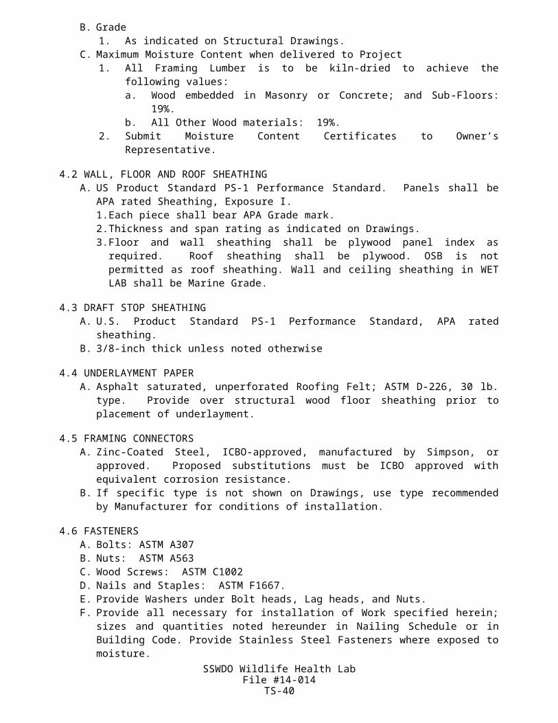
8.3 VAPOR BARRIERA. Provide beneath Insulation at ceilings, roofs, walls, and as indicated on Drawings.
Polyethylene Film, "Visqueen" or approved, 6-mil thickness, with Vapor Transmission Rating of 0.10 perms.
8.4 MECHANICAL FASTENERSA. Type recommended by Insulation Manufacturer.B. Long enough to penetrate substrate ½ inch, minimum
PART 9 - EXECUTION
9.1 EXISTING CONDITIONS A. Verify that Work of preceding Trades is completed. B. Verify that surfaces and spaces to receive Insulation are accurately sized, located, dry,
protected against inclement weather, clean, and otherwise properly prepared. C. Prior to starting Work notify General Contractor of defects requiring correction. D. Do not start Work until conditions are satisfactory.
9.2 PREPARATION OF SURFACES A. Remove, or protect against projections which may damage Insulation or prevent proper
installation.
9.3 NOTICES A. Notify Owner’s Representative at least 24 hours prior to completing Insulation Work for
inspection.
9.4 INSTALLATION A. General
1. Follow Manufacturer's directions. 2. Fit Insulation snugly between Framing without forcing. 3. Permit no gaps for air passage. 4. Carefully cut and fit Insulation around Pipes, Conduits, and other obstructions. 5. Where Pipes, Conduit, and other obstructions are located in space to receive
Insulation, place Insulation between cold-in-winter surface and obstruction, compressing Insulation where necessary. Except where indicated above, do not compress Insulation more than 10%.
9.5 FLEXIBLE MINERAL WOOL TYPE INSULATION A. Install Insulation with Vapor Barrier facing warm-in-winter side of Assembly. B. Use full-length, single-piece Batts where practicable. C. Staple Facing Flanges to Wood Framing, 8 inches o.c. maximum. Provide additional Wire
support as necessary to prevent Insulation displacement or sagging.
9.6 RIGID INSULATION AT WALL HEADERSA. Install with Adhesive recommended by Insulation Manufacturer.
9.7 POLYETHYLENE SHEET VAPOR BARRIERA. Install continuous without gaps at warm side of all above-grade insulation. Lap sheets
and vertical/horizontal transitions a minimum of 3 inches over a continuous Sealant Bead, and staple edges to top plates, overlapping wall insulation by 3 inches.
9.8 PRODUCT CLEANING AND REPAIRING A. Including Work of other Sections, clean, repair, and touch-up, or replace when directed,
products which have been soiled, discolored, or damaged by Work of this Section. Remove debris from Project Site upon Work completion or sooner, if directed.
SSWDO Wildlife Health LabFile #14-014
TS-40

END OF SECTION 07200
SSWDO Wildlife Health LabFile #14-014
TS-41

SECTION 07400 -PREFORMED METAL ROOFING
PART 1 - GENERAL
1.1 SUMMARYA. Work covered by this section consists of furnishing all plant, labor, appliances and
materials, and performing all operations required to complete the metal roof system, including panels, panel clips, flashing, panel splices, guts, framing for soffits and fascias, fascia panels and all necessary fasteners, sub structural supports, accessories, and sealants as shown on the Drawings and as specified herein.
1.2 SUBMITTALSA. All submittals shall conform to the Supplemental General Conditions.B. Product data: Submit manufacturer’s descriptive literature including installation
instructions for all products specified herein.C. Shop drawings: Submit drawings for fabrication and installation of metal roof system.D. Show layout of metal panels and details of fasteners, trim, closures, and related items.E. Samples: Submit two samples 12” x 12” in size illustrating color and texture of finish and
profile of ribs.
1.3 QUALITY ASSURANCEA. Manufacturer: Company specializing in metal roof systems with five years’ experience.B. Applicator: Company approved by manufacturer.
1.4 WARRANTYA. Provide ten year manufacturer’s warranty to the Engineer for material and installation.B. Warranty: Cover roof system against leakage. Cover roofing finish against cracking,
peeling, blistering, and fading in excess of limitations specified herein.
PART 2 - PRODUCTS
2.1 MATERIALSA. Roofing shall be standing seam design; concealed fastener system with rib configuration
and color to be selected by Owner.B. Sheet steel: ASTM A366; galvanized with G-90 zinc coating and finished before roll-
forming.1. Gauge: As required for wind loading, but not less than 24.2. Trim: Minimum 26 gauge.C. Base coat: Two-component epoxy paint; minimum dry film thickness 2.9 mils; apply to
both sides of panels.D. Finish coat: Acrylic enamel or silicone-modified polyester; baked at minimum 300° F
after application; film thickness as required to meet Performance Requirements specified above.
E. Color per Owner.
2.2 ACCESSORIESA. Manufacturer’s standard flexible transition boot for vent pipes and small roof
penetrations.B. Manufacturer’s elastomeric rib caps, composition closure strips, and metal closure strips.
2.3 PERFORMANCE REQUIREMENTSA. Finish: Contractor shall submit manufacturer’s certification that the requirements of the
following tests are met by the product.SSWDO Wildlife Health Lab
File #14-014TS-42

1. Color change and fade resistance: a sample shall withstand a minimum of 60 days EMMAQUA weathering test exposure (Exterior Equatorial mount with mirrors and water spray) and/or 200,000 Langleys of ultraviolet radiation without cracking, peeling, blistering, or loss of adhesion. Maximum color change, after removal of all exterior or surface deposits such as dirt, or chalk, shall not exceed 2 NBS units.
2. Abrasion resistance test for coating system: A flat specimen shall be subjected to abrasion resistance test. Test shall be conducted in accordance with ASTM D968 (Falling Sand). Coating system shall resist abrasion to extent indicated by use of not less than 100 liters of sand to produce the exposure of 3.9 mm diameter area of bare metal.
3. Coating systems integrity test: A sample shall withstand a salt-fog test for a minimum of 1,250 hours in accordance with ASTM B117, including scribe requirement in test. Immediately upon removal of specimen from test, coating system shall show no signs of cracking, peeling, blistering, or loss of adhesion.
4. Humidity resistance test: A sample shall be tested for 1,000 hours at 100° F in accordance with ASTM D2247 with no blistering, peeling, or loss of adhesion.
B. Structural1. Maximum allowable deflection: L/240 for each span.2. Loads as noted on the Drawings.3. Wind Uplift: In accordance with the International Building Code, 2003 Edition.
PART 3 - EXECUTION
3.1 INSPECTIONA. Verify the surfaces and structural members to receive roof/soffit system are sound and
properly aligned.B. Beginning of installation means acceptance of existing surfaces and structural members.
3.2 INSTALLATION AND ERECTIONA. Install metal roof panels, fascia/soffit panels, fasteners, rib caps, trim, closures, and
related items in accordance with approved shop drawings and manufacturer’s specifications.
B. All installation by workmen considered by manufacturer shall be qualified installers.C. Set units true to line, without warp. Anchor securely in place.
3.3 DAMAGED MATERIALA. Repair or replace damaged material to the satisfaction of the Engineer at no additional
cost to the State.
SSWDO Wildlife Health LabFile #14-014
TS-43
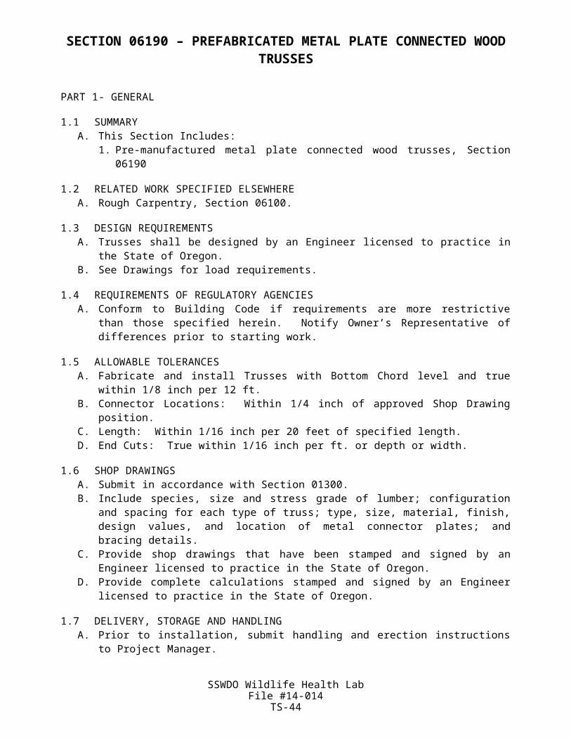
SECTION 07600 – GENERAL SHEETMETAL
PART 1 - GENERAL
9.9 SUMMARYA. This Section Includes:
1. General sheetmetal and flashing.2. Gutters and downspouts.
9.10RELATED WORK SPECIFIED ELSEWHEREA. Wood Blocking and Nailers, Section 06100.B. Building Caulking and Sealing, Section 07951.
9.11SUBMITTALSA. Shop Drawings: Show joints, types and locations of fasteners and special shapes.
9.12PRODUCT DELIVERY, STORAGE AND HANDLINGA. Protect against damage and discoloration.B. Store off ground.
9.13WARRANTYA. Warrant Work weather tight for 2 years.
PART 10 - PRODUCTS
10.1SHEETMETALA. Galvanized Steel
1. ASTM A-446; coating designation C-90; lock-forming quality conforming to ASTM A-527.
2. Exposed surfaces factory-coated with two-coat, thermocured fluoropolymer finish per AAMA 2604. Provide at all sheetmetal work.
10.2NAILSA. Flat head, wire, barbed, slating type, conforming to Fed. Spec. FF-N-105B, Type II, Style
23.B. Galvanized Steel, 1 inch long, 12 gauge, minimum.
10.3SCREWSA. Pan head, self-tapping, sheetmetal type, conforming to Fed. Spec. FF-S-107; #7 by one
inch long minimum, Cadmium plated.
10.4RIVETSA. 1/8-inch minimum diameter, length as recommended by Rivet Manufacturer for materials
to be joined; Cadmium plated.
10.5EXPANSION ANCHORSA. Type recommended by Manufacturer by conditions of use.
10.6SOLDERA. ASTM B-32; 50% Tin and 50% Lead.
10.7FLUXA. Rosin, cut muriatic acid, or commercial preparation for material to be soldered.
SSWDO Wildlife Health LabFile #14-014
TS-44
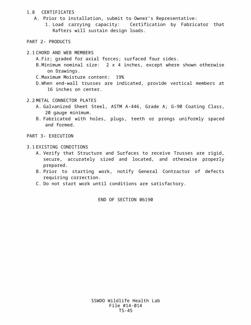
10.8SEALANTA. Silicone type; Dow, GE, or approved.
10.9ASPHALT PLASTIC CEMENTA. Fed. Spec. SS-C-153, Type 1.
10.10 OPEN VALLEY FLASHING UNDERLAYMENTA. Asphalt-saturated, unperforated Roofing Felt; ASTM D-226, 30 lb. type.
10.11 DOWNSPOUT BRACKETSA. Galvanized 16 gauge.B. Elcen Brackets.
10.12 FABRICATIONA. General
1. Form to shapes and dimensions shown with planes and lines in true alignment.2. Unless otherwise shown on Drawings or specified, fabricate with longest
practicable lengths.3. Hem exposed edges.4. Angle bottom edges of vertical surfaces to form drip.
B. Cleats5. Same Material and thickness as Sheetmetal.
PART 11 - EXECUTION
11.1EXISTING CONDITIONSA. Verify that surfaces to receive Sheetmetal are smooth, clean, and otherwise properly
prepared.B. Verify that Nailers to receive Sheetmetal are properly placed.C. Prior to starting work, notify General Contractor of defects that require correction.D. Do not start Work until conditions are satisfactory.
11.2FIELD MEASUREMENTSA. Before fabricating Sheetmetal, verify shapes and dimensions of surfaces to be covered.B. If field measurements differ slightly from Drawing dimensions, modify Work as required for
accurate fit. If measurements differ substantially, notify Owner’s Representative prior to fabrication.
11.3INSTALLATION, GENERALA. Install work weather tight, without waves, warps, buckles, tool marks, fastening stresses,
distortion or defects which impair strength or mar appearance.B. Install planes and lines to true alignment.C. Allow for Sheetmetal expansion and contraction.
11.4SEAM INSTALLATIONA. Flat Lock Seams
1. 5/8-inch finish width; 4-ply flat-locked, malleted tight; sweat full with Solder.B. Single Corner Seams
1. 3/4-inch finish width; 3-ply loose locked.C. Double Corner Seams
1. 5/8-inch finish width; 4-ply loose locked.D. Lap Seams
1. 3-inch finish width.
SSWDO Wildlife Health LabFile #14-014
TS-45
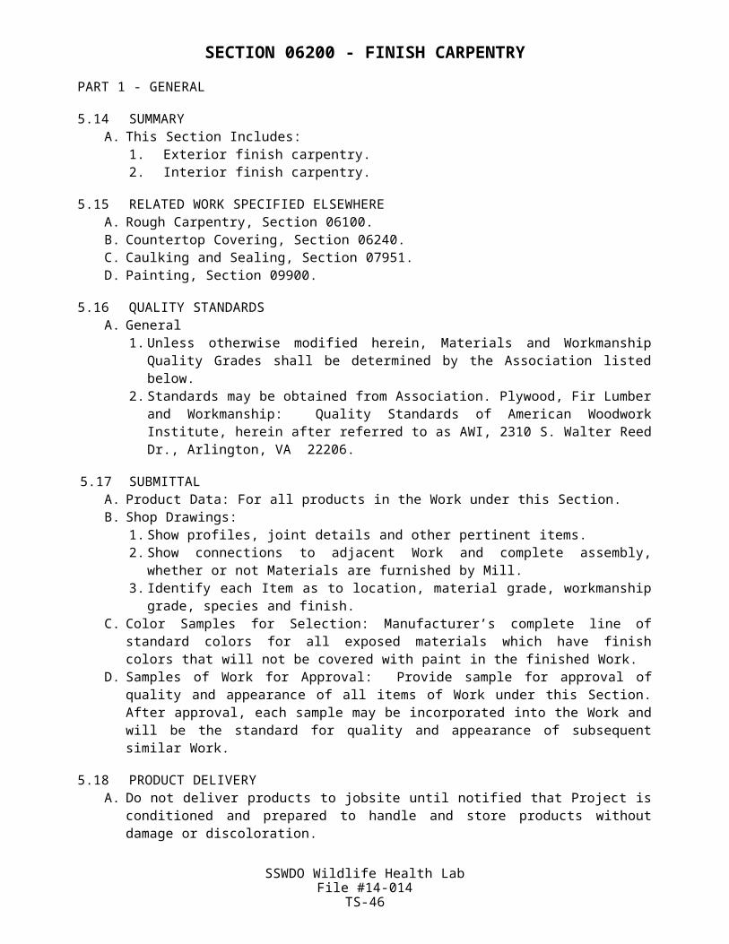
E. Cover Plate Seams1. Space abutting Sheets ½ inch; cover joint with 4-inch wide Cover and Match Plates
to Flashing profile.2. Secure Plates to Substrate with screw installed through open space between
Flashing Sheets.F. S-Lock Seams
1. Form 1-1/4-inch wide "S" shaped Seam on one edge of Flashing Sheet for concealed fastening.
11.5CLEAT INSTALLATIONA. Space 2 feet on center, unless continuous Cleats or other spacings are specified
hereunder.B. Secure spaced Cleats to Substrate with 2 FastenersC. Secure continuous Cleats to Substrate with Fasteners spaced at 12-inch maximum
centers.D. Cover fastener Heads with Cleat Tabs.
11.6 SEALANT INSTALLATIONA. Apply 1/4-inch diameter bead, centered in full length of joint.
11.7 ASPHALT PLASTIC CEMENT INSTALLATIONA. Trowel apply 1/8-inch thick.
11.8COUNTER FLASHINGA. Form of 24-gauge minimum galvanized steel.B. Overlap Base Flashing 4 inches minimum.C. Install bottom edge spring-tight against base Flashing, or at Contractor's option secure
bottom edge with 1-inch wide Clips spaced no greater than 24 inches o.c. Attach Clips to Substrate with concealed Fasteners. Reinforce Clips by double-bending back over bottom edge of Counter Flashing 3/4 inch.
D. Lap-Seam vertical joints, and apply Sealant.E. Provide where roof intersects vertical surfaces, and elsewhere shown on Drawings.
11.9ROOF PENETRATION FLASHINGA. General
1. Form of 26 gauge minimum galvanized steel.2. Extend Flange onto Roof 6 inches minimum in all directions away from Penetration,
and upward around Penetration to position at least 2 inches above Roof flood line.3. Solder-Lap joints.4. Furnish to Roofer for installation.
B. Counter Flashing1. Overlap Base Flashing at least 1 inch wide with storm collar sloped away from
Penetration.5. Secure to Penetration with Draw Band and Sealant.
C. Miter and extend around corner 3 inches minimum and solder joints.D. Install bottom edge spring-tight against roofing.
11.10 RAKE FLASHINGA. Form of 26 gauge minimum Galvanized Steel.B. Extend horizontal flange 3 inches under roofing and nail to substrate.C. Extend vertical flange as shown on Drawings.D. Lap-seam joints in direction of water flow.
SSWDO Wildlife Health LabFile #14-014
TS-46

11.11 HUNG GUTTERSA. Form to detail of 20 gauge minimum Aluminum, with "ogee" profile, 5 inch width x 3-3/4
inch height.B. Lap joints 1-inch minimum and solder.C. Locate outer edge ½-inch lower than back edge.D. Stiffen outer edge with hemmed return.E. Counter flash back edge.F. Secure end caps with 1 inch minimum with Flanges riveted and soldered to gutter.G. Secure Gutter to Rafters with Gutter Screws and Ferrules spaced 4 ft. o.c. maximum.H. Provide Expansion Joints midway between Downspouts; overlap Gutter sections 2-1/2
inches and provide end caps spaced ½ inch apart.I. Cover Expansion Joint tops with loose-lock cover; extend Cover over outer edge of
Gutter and embed in Sealant.J. Size thimble 1/8 inch less than Downspout and extend 2 inches below Gutter bottom.K. Rivet and solder thimble flanges to Gutter bottom.
11.12 DOWNSPOUT STRAINERSA. Removable wire basket type, 0.054 inch minimum wire size, same material as
Downspout.B. Provide one in each Downspout Inlet, fit tight.
11.13 DOWNSPOUTSA. Form of uncorrugated 26 gauge minimum Aluminum. 3-inch x 3-inch size.B. Fabricate longitudinal joints with double corner seams.C. Telescope upper into lower sections 1-1/2 inches minimum, rivet and solder.D. Attach to wall with 1-1/4 inch wide straps matching downspout material, and 2 gauge
heaver.E. Locate straps at downspout tops, bottoms, horizontal joints, and 10 ft. maximum centers.F. Except where otherwise shown on Drawings, install downspouts plumb; modify straps if
necessary.G. Extend downspouts 3 inches minimum onto splash blocks.
11.14 MISCELLANEOUS FLASHINGA. Provide Flashing around Doors, Louvers, and other openings in exterior Walls where
indicated or required to maintain Building watertight.
11.15 CLEANING AND REPAIRINGA. As Work progresses, neutralize excess Flux with 5% to 10% Washing Soda Solution and
thoroughly rinse.B. Including Work of other Sections, clean, repair and touch-up, or replace when directed,
Products which have been soiled, discolored, or damaged by work of this Section.C. Remove debris from Project Site upon Work completion or sooner, if directed.
END OF SECTION 07600
SSWDO Wildlife Health LabFile #14-014
TS-47

SECTION 07900 - CAULKING AND SEALANTS
PART 1 – GENERAL
1.1 SUMMARYA. This Section Includes:
1. Caulking and sealants.
1.2 RELATED WORK SPECIFIED ELSEWHERE A. Sealing Sheet Metal Joints, Section 07600. B. Glazing Compounds, Section 08800.
1.3 EXTENT OF WORK A. Caulk where shown on Drawings and at all exterior joints.B. Caulk exterior joints around meter bases, window frames, door frames, expansion joints,
and other openings in exterior walls, which are subject to moisture infiltration, with STPe type sealant.
C. Fill space beneath exterior door thresholds with latex acrylic sealant.
1.4 CERTIFICATE OF COMPLIANCE A. Submit prior to starting work, manufacturer's written certification that specified sealants are
suitable for intended use.B. Submit upon work completion, manufacturer's written certification that specified sealant
has been properly mixed and installed.
1.5 APPLICATOR QUALIFICATIONS A. Applicator shall have at least three years experience in installing products specified on
similar sized projects.
1.6 PRODUCT DELIVERY, STORAGE AND HANDLING A. Protect against damage and cold temperatures. B. Store in original, tightly sealed containers, and with original legible labels thereon. C. Do not open containers or remove labels until Owner’s Representative reviews.
1.7 WEATHER DURING WORK A. Perform no Work when weather exceeds manufacturer's specified limits.
1.8 WARRANTY
A. Provide 20-year warranty for Caulking and Sealing Work.
PART 2 - PRODUCTS
2.1 STPe SEALANT A. Sonolastic 150 with VLM Technology or approved.B. Multi-component tintable, non-sag, silyl-terminated polyether elastomeric sealant.
2.2 LATEX ACRYLIC SEALANT A. Pecora AC-20, Sonneborn Sonnolac Acrylic, or approved.
2.3 COLOR OF EXPOSED SEALANT A. Approximate color of adjacent surfaces, unless otherwise directed.
2.4 PRIMER AND SURFACE CONDITIONER A. Made or recommended by sealant manufacturer.
SSWDO Wildlife Health LabFile #14-014
TS-48
2.5 BACKER ROD A. Soft Backer Rod.B. Reticulated closed cell polyethylene foam joint filler and backing for sealants.C. Use a backer-rod diameter that is approximately 25% larger than the width of the joint.
2.6 MIXINGA. Follow sealant manufacturer's directions.
PART 3 - EXECUTION
3.1 EXISTING CONDITIONS A. Verify that joints to be sealed and filled are clean, dry, and free from dust, oil, grease, rust,
lacquer, laitance, loose mortar, or other bond reducing matter. B. Allow concrete surfaces to dry at least 4 weeks before caulking or sealing. C. Prior to starting work, notify General Contractor of defects requiring correction.
3.2 SURFACE PREPARATION A. Surfaces to receive sealant must be structurally sound, dry, clean, free of dirt, moisture,
loose particles, oil, grease, asphalt, tar, paint, wax, rust, waterproofing or curing compounds or any type of membrane material.
B. Remove dust and dirt by brushing and air blowing. C. Mock-up area of sealant applications, both on primed and unprimed surfaces, to establish
quality standards. Notify Owner’s Representative for review, before proceeding.
3.3 PRIMING A. Prime surfaces as required by manufacturer's instructions. Apply with bristle brush. B. Do not flood surfaces.
3.4 BACKING INSTALLATIONA. Joints to Receive Latex Acrylic Sealant
1. If Joints are deeper than 3/4 inch and no suitable backstop is provided, pack joints with rope yarn to within ½ inch of surface.
B. Joints to Receive STPe Sealant1. Install Backer Rod behind Sealant in accordance with Manufacturer's directions, using
a blunt probe. Do not stretch backer rod during installation.2. Dry install STPe at median temperature (above 40° F).3. Provide in as long continuous lengths as practicable. 4. Stretch taut and force into Joints to uniform depth, approximately ½ joint width but not
to exceed 5/8 inch.
3.5 SEALANT INSTALLATION A. Mix and apply in accordance with manufacturer's directions using gun type dispenser. B. Seal joints before applying final Paint coat. C. Size gun nozzle to fit joint. D. Fill joints and voids solid; superficial pointing with skin bead not acceptable. Fill joints from
the bottom up to the exterior face.E. Install flush with adjacent surfaces. F. Tool joints smooth within 10 minutes after installation. G. Remove masking materials, if any, immediately after sealant installation.
3.7 CLEANING A. Remove excess material as work progresses and leave surfaces neat, smooth, and clean. B. Remove debris from project site upon work completion or sooner, if directed. C. Including work of other sections, clean, repair and touch up, or replace when directed,
products which have been soiled, discolored, or damaged by work of this section.SSWDO Wildlife Health Lab
File #14-014TS-49

END OF SECTION 07900
SSWDO Wildlife Health LabFile #14-014
TS-50
SECTION 08100 - METAL DOORS AND FRAMES
PART 1 GENERAL
1.1 SUMMARYA. The work covered by this section consists of furnishing all plant, labor, equipment, and
materials, and performing all operations required to complete hollow metal doors, frames, and overhead steel doors shown on the Drawings. All such work to be as shown on the Drawings and specified herein.
1.2 SUBMITTALSA. General: Submit listed submittals in accordance with General Conditions of the Contract
and Section 01300 Submittal Procedures.B. Product Data: Submit product data, including manufacturer’s product sheet, for specified
products.C. Shop Drawings: Submit shop drawings showing layout, profiles and product components,
including anchorage, accessories and finish colors.1. Indicate door type, frame, steel, core, material thickness, reinforcements, anchorages, exposed fasteners locations, openings (glazed, paneled or louvered) and hardware arrangement.
D. Samples: Submit selection and verification samples for finishes, colors and textures. Coordinate with Section 09900 Painting for paint finishes.
E. Quality Assurance Submittals: Submit the following:1. Certificates: Product certificates signed by manufacturer certifying that materials comply with specified performance characteristics and criteria and physical requirements.2. Manufacturer’s Instructions: Manufacturer’s installation instructions.
F. Closeout Submittals: Submit the following:1. Operation and Maintenance Data: Operation and maintenance data for installed products in accordance with Section 01010 Closeout Submittals (Maintenance Data and Operation Data) Section. Include methods for maintaining installed products and precautions against cleaning materials and methods detrimental to finishes and performance.2. Warranty: Warranty documents specified herein.
G. Project Warranty: Refer to Conditions of the Contract for project warranty provisions.H. Manufacturer’s Warranty: Submit, for Owner’s acceptance, manufacturer’s standard
warranty document executed by authorized company official. Manufacturer’s warranty is in addition to, and not a limitation of, other rights Owner may have under Contract Documents.
1. Warranty Period: 2 years commencing on date of Substantial Completion.
PART 2 PRODUCTS
2.1 HOLLOW METAL DOORSA. Shall be flush construction equal to LF series as manufactured by STEELCRAFT
MANUFACTURING CO., Cincinnati, OH.B. All exterior hollow metal doors shall be 1-3/4 inch thick.C. Doors shall be fabricated of galvanized steel, 18 gage. Doors shall be reinforced,
stiffened sound deadened and insulated with impregnated kraft honeycomb core completely filling the inside of the doors and laminated to both inside faces of the panels. Doors shall have continuous vertical mechanical interlocking joints at lock and hinge edges with edge seams welded and filled and ground smooth. Hinge and lock edges shall be beveled 1/8 inch in 2 inches. Top and bottom 14 gage cold rolled steel reinforcing channels shall be spot welded within the door. Hinge reinforcing shall be 8 gage, lock reinforcing shall be 16 gage, and closer reinforcing shall be 12 gage.
SSWDO Wildlife Health LabFile #14-014
TS-51

Adequate reinforcing shall be provided for other hardware as required. All doors shall be bonderized and finished as standard with one coat of baked-on prime paint capable of passing a 240 hour salt spray and a 1,000 hour humidity test, in accordance with Federal Standard 141A or ASTM, Specification B117 as certified by an independent laboratory. Painted finish shall be 2 coats of oil base exterior trim paint applied by brush. Color shall be selected by the Owner.
D. Exterior doors shall be equipped with door shoes, PEMKO No. 222AV, or equal, and shall be provided with a keyed lock, equal to SCHLAGE classroom lock, Series 4000, satin bronze finish.
E. Shop drawings which clearly show details of construction and installation shall be submitted for approval prior to fabrication. Thresholds For exterior doors shall be equal to PEMKO No. 170A.
F. Exterior doors shall be compatible with a card reader Lock System. See Specification Section 08710 for card reader system details.
2.2 METAL FRAMESA. Metal frames for hollow metal doors shall be equal to F-16 series as manufactured by
STEELCRAFT MANUFACTURING CO., Cincinnati, OH.. Frames shall be formed from 16 gage galvanized steel with 2 inch faces. Frames shall be set up and welded. Mitered corners shall have reinforcements with integral tabs for secure inter-locking of jambs to head. Strike jambs shall be supplied with three factory installed rubber bumpers and heads of pairs of doors with two rubber bumpers. Frames shall have 8 gage steel hinge reinforcing and shall be mortised for 4-1/2 inch by 4-1/2 inch standard weight template hinges, 1-1/2 pair per door. Strike reinforcing shall be 12 gage steel and mortised for ASA 115.1 Universal Strike. Provide metal plaster guard for all mortised cutouts. Reinforcing for surface closer shall be 12 gage steel. Adequate reinforcing shall be provided for all other hardware when required.
B. Frames shall be furnished with a minimum of 6 wall anchors and two adjustable base anchors of manufacturer's standard design. All frames shall be bonderized and finished as standard with one coat of baked-on prime paint. Painted finish shall be similar to doors.
C. Frames for exterior doors shall be weather stripped.D. Shop drawings which clearly show details of construction and installation shall be
submitted for approval before fabrication is begun.E. Metal frames shall be compatible with a card reader lock system. See Specification
Section 08710 for card reader system details.
PART 3 EXECUTION
3.1 INSTALLATIONA. Doors shall be accurately sized for proper clearance and shall be carefully set to insure
proper door fit requiring no further cutting of any door, and shall be mortised, drilled and otherwise worked for finish hardware.
B. Installation shall be true, plumb and accurate. Doors and frames shall be installed in full compliance with manufacturer's printed instructions. All doors shall open and close smoothly and free of binding, interference and other defects or objectionable characteristics associated with poor installation or alignment, or improper adjustment.
END OF SECTION 08100
SSWDO Wildlife Health LabFile #14-014
TS-52
SECTION 08211 - FLUSH WOOD DOORS
PART 1 - GENERAL
1.1 RELATED DOCUMENTSB. Drawings and general provisions of the Contract, including General and Supplemental
Conditions and Specification Section 01010, 01300, 01500, apply to this Section.
1.2 SUMMARYA. Section Includes:
1. Solid-core doors with wood-veneer faces.2. Factory finishing flush wood doors.3. Factory fitting flush wood doors to frames and factory machining for hardware.
B. Related Sections:1. Section 08100“Metal Doors and Frames” for frames for flush wood doors.2. Section 08710 “Hardware” for hardware preparation requirements for flush wood
doors.
1.3 SUBMITTALSA. Product Data: For each type of door indicated. Include details of core and edge
construction, louvers, and trim for openings. Include factory-finishing specifications.B. Shop Drawings: Indicate location, size, and hand of each door; elevation of each kind
of door; construction details not covered in Product Data; location and extent of hardware blocking; and other pertinent data.
1. Indicate dimensions and locations of mortises and holes for hardware.2. Indicate dimensions and locations of cutouts.3. Indicate requirements for veneer matching.4. Indicate doors to be factory finished and finish requirements.5. Indicate fire-protection ratings for fire-rated doors.
C. Samples for Initial Selection: For factory-finished door veneers.D. Samples for Verification:
1. Factory finishes applied to actual door face materials, approximately 8 by 10 inches, for each material and finish. For each wood species and transparent finish, provide set of three samples showing typical range of color and grain to be expected in the finished work.
2. Corner sections of doors, approximately 8 by 10 inches (200 by 250 mm), with door faces and edges representing actual materials to be used.a. Provide samples for each species of veneer and solid lumber required.b. Finish veneer-faced door samples with same materials proposed for factory-
finished doors.3. Louver blade and frame sections, 6 inches long, for each material and finish specified.4. Frames for light openings, 6 inches long, for each material, type, and finish required.
E. Warranty: Sample of special warranty.
1.4 QUALITY ASSURANCEA. Source Limitations: Obtain flush wood doors from single manufacturer.B. Quality Standard: In addition to requirements specified, comply with WDMA I.S.1-A,
"Architectural Wood Flush Doors."C. Pre-installation Conference: Conduct conference at Project site.
1.5 DELIVERY, STORAGE, AND HANDLINGA. Comply with requirements of referenced standard and manufacturer's written
instructions.B. Package doors individually in cardboard cartons and wrap bundles of doors in plastic
SSWDO Wildlife Health LabFile #14-014
TS-53

sheeting.C. Mark each door on top and bottom rail with opening number used on Shop Drawings.
1.6 PROJECT CONDITIONSA. Environmental Limitations: Do not deliver or install doors until spaces are enclosed
and weather tight, wet work in spaces is complete and dry, and HVAC system is operating and maintaining temperature between 60 and 90 deg F (16 and 32 deg C) and relative humidity between 25 and 55 percent during the remainder of the construction period.
1.7 WARRANTYA. Special Warranty: Manufacturer's standard form in which manufacturer agrees to
repair or replace doors that fail in materials or workmanship within specified warranty period.
1. Failures include, but are not limited to, the following:a. Warping (bow, cup, or twist) more than 1/4 inch (6.4 mm) in a 42-by-84- inch
(1067-by-2134-mm) section.b. Telegraphing of core construction in face veneers exceeding 0.01 inch in a
3-inch (0.25 mm in a 76.2-mm) span.2. Warranty Period for Solid-Core Interior Doors: Life of installation.
PART 2 - PRODUCTS
2.1 MANUFACTURERSA. Manufacturers: Subject to compliance with requirements, provide products by one of
the following:1. Algoma Hardwoods, Inc.2. Ampco, Inc.3. Buell Door Company Inc.4. Chappell Door Co.5. Eagle Plywood & Door Manufacturing, Inc.6. Eggers Industries.7. Graham; an Assa Abloy Group company.8. Haley Brothers, Inc.9. Ideal Architectural Doors & Plywood.10. Ipik Door Company.11. Lambton Doors.12. Marlite.13. Marshfield Door Systems, Inc.14. Mohawk Flush Doors, Inc.; a Masonite company.15. Oshkosh Architectural Door Company.16. Poncraft Door Company.17. Vancouver Door Company.18. VT Industries Inc.
2.2 DOOR CONSTRUCTION, GENERALA. WDMA I.S.1-A Performance Grade: Extra Heavy Duty.
B. Structural-Composite-Lumber-Core Doors:1. Structural Composite Lumber: WDMA I.S.10.
a. Screw Withdrawal, Face: 700 lbf (3100 N). b. Screw Withdrawal, Edge: 400 lbf (1780 N).
C. Fire-Protection-Rated Doors: Provide core specified or mineral core as needed to provide fire-protection rating indicated.
1. Edge Construction: Provide edge construction with intumescent seals concealed
SSWDO Wildlife Health LabFile #14-014
TS-54
by outer stile. Comply with specified requirements for exposed edges.2. Pairs: Provide fire-retardant stiles that are listed and labeled for applications indicated without formed-steel edges and astragals. Comply with specified requirements for exposed edges.
2.3 VENEERED-FACED DOORS FOR TRANSPARENT FINISHA. Interior Solid-Core doors:
1. Grade: Premium, with Grade A faces.2. Species: Red oak.3. Cut: Rift cut.4. Match between Veneer Leaves: Slip match.5. Assembly of Veneer Leaves on Door Faces: Running match.6. Pair and Set Match: Provide for doors hung in same opening.7. Room Match: Provide door faces of compatible color and grain within each
separate room or area of building.8. Exposed Vertical Edges: Same species as faces.9. Core: Structural composite lumber.10. Construction: Five plies. Stiles and rails are bonded to core, then entire unit abrasive
planed before veneering.11. WDMA 1.S.1-A Performance Grade: Extra Heavy Duty.
2.5 FABRICATIONA. Factory fit doors to suit frame-opening sizes indicated. Comply with clearance
requirements of referenced quality standard for fitting unless otherwise indicated.1. Comply with requirements in NFPA 80 for fire-rated doors.
B. Factory machine doors for hardware that is not surface applied. Locate hardware to comply with DHI-WDHS-3. Comply with final hardware schedules, door frame Shop Drawings, DHI A115-W series standards, and hardware templates.1. Coordinate with hardware mortises in metal frames to verify dimensions and
alignment before factory machining.2. Metal Astragals: Factory machine astragals and formed-steel edges for
hardware for pairs of fire-rated doors.
2.6 FACTORY FINISHINGA. General: Comply with referenced quality standard for factory finishing. Complete
fabrication, including fitting doors for openings and machining for hardware that is not surface applied, before finishing.1. Finish faces, all four edges, edges of cutouts, and mortises. Stains and fillers
may be omitted on bottom edges, edges of cutouts, and mortises.B. Finish doors at factory.C. Finish doors at factory that are indicated to receive transparent finish. Field finish
doors indicated to receive opaque finish.
D. Finish doors at factory where indicated in schedules or on Drawings as factory finished. E. Transparent Finish:1. Grade: Premium.2. Finish: WDMA TR-6 catalyzed polyurethane.3. Staining: As selected by Architect from manufacturer's full range.4. Effect: Open-grain finish.
5. Sheen: Satin.
PART 3 - EXECUTION
SSWDO Wildlife Health LabFile #14-014
TS-55

3.1 EXAMINATIONA. Examine doors and installed door frames before hanging doors.
1. Verify that frames comply with indicated requirements for type, size, location, and swing characteristics and have been installed with level heads and plumb jambs.
2. Reject doors with defects.B. Proceed with installation only after unsatisfactory conditions have been corrected.
3.2 INSTALLATIONA. Hardware: For installation, see Section 08710.B. Installation Instructions: Install doors to comply with manufacturer's written instructions
and the referenced quality standard, and as indicated.1. Install fire-rated doors in corresponding fire-rated frames according to NFPA 80.
C. Job-Fitted Doors: Align and fit doors in frames with uniform clearances and bevels as indicated below; do not trim stiles and rails in excess of limits set by manufacturer or permitted for fire-rated doors. Machine doors for hardware. Seal edges of doors, edges of cutouts, and mortises after fitting and machining.1. Clearances: Provide 1/8 inch (3.2 mm) at heads, jambs, and between pairs of
doors. Provide 1/8 inch (3.2 mm) from bottom of door to top of decorative floor finish or covering unless otherwise indicated. Where threshold is shown or scheduled, provide 1/4 inch (6.4 mm) from bottom of door to top of threshold unless otherwise indicated.
a. Comply with NFPA 80 for fire-rated doors.2. Bevel non-fire-rated doors 1/8 inch in 2 inches (3-1/2 degrees) at lock and hinge
edges.3. Bevel fire-rated doors 1/8 inch in 2 inches (3-1/2 degrees) at lock edge; trim stiles and
rails only to extent permitted by labeling agency.D. Factory-Fitted Doors: Align in frames for uniform clearance at each edge.E. Factory-Finished Doors: Restore finish before installation if fitting or machining is
required at Project site.
3.3 ADJUSTINGA. Operation: Rehang or replace doors that do not swing or operate freely.B. Finished Doors: Replace doors that are damaged or that do not comply with
requirements. Doors may be repaired or refinished if work complies with requirements and shows no evidence of repair or refinishing.
END OF SECTION 08211
SSWDO Wildlife Health LabFile #14-014
TS-56
SECTION 08 33 00 – OVERHEAD COILING SERVICE DOORS
PART 1 GENERAL 1.1 SECTION INCLUDES A. Overhead coiling service doors.
1.2 RELATED SECTIONS A. Section 06 20 00 - Finish Carpentry: Wood jamb and head trim. B. Section 09 90 00 - Painting: Field applied finish.
1.3 REFERENCES A. NFRC 102 - Test Procedure for Measuring the Steady-State Thermal Transmittance of
Fenestration Systems. B. ASTM E 90 - Standard Test Method for Laboratory Measurement of Airborne Sound
Transmission Loss of Building Partitions and Element. C. ASTM E 330 - Standard Test Method for Structural Performance of Exterior Windows,
Doors, Skylights and Curtain Walls by Uniform Static Air Pressure Difference. D. ASTM A 653 - Standard Specification for Steel Sheet, Zinc-Coated (Galvanized) or
Zinc- Iron Alloy-Coated (Galvannealed) by the Hot-Dip Process. E. ASTM A 666 - Standard Specification for Austenitic Stainless Steel Sheet, Strip, Plate,
and Flat Bar. F. ASTM A 924 - Standard Specification for General Requirements for Steel Sheet,
Metallic- Coated by the Hot-Dip Process. G. ASTM B 221 - Standard Specification for Aluminum and Aluminum-Alloy Extruded
Bars, Rods, Wire, Profiles, and Tubes. H. NEMA 250 - Enclosures for Electrical Equipment (1000 Volts Maximum). I. NEMA MG 1 - Motors and Generators.
1.4 DESIGN / PERFORMANCE REQUIREMENTS A. Overhead coiling insulated doors: B. Wind Loads: Design door assembly to withstand wind/suction load of 20 psf without
damage to door or assembly components in conformance with ASTM E 330. C. Operation: Design door assembly, including operator, to operate for not less than
20,000 cycles. D. Single-Source Responsibility: Provide doors, tracks, motors, and accessories from
one manufacturer for each type of door. Provide secondary components from source acceptable to manufacturer of primary components.
E. Products Requiring Electrical Connection: Listed and classified by Underwriters Laboratories, Inc. acceptable to authority having jurisdiction as suitable for purpose specified.
1.5 SUBMITTALS A. Submit under provisions of Section 01 33 00. B. Product Data: Manufacturer's data sheets on each product to be used, including:
SSWDO Wildlife Health LabFile #14-014
TS-57
C. Preparation instructions and recommendations. D. Storage and handling requirements and recommendations. E. Details of construction and fabrication. F. Installation instructions. G. Shop Drawings: Include detailed plans, elevations, details of framing members,
anchoring methods, required clearances, hardware, and accessories. Include relationship with adjacent construction.
H. Selection Samples: For each finish product specified, two complete sets of color chips representing manufacturer's full range of available colors and patterns.
I. Verification Samples: For each finish product specified, two samples, minimum size 6 inches (150 mm) long, representing actual product, color, and patterns.
J. Manufacturer's Certificates: Certify products meet or exceed specified requirements. K. Operation and Maintenance Data: Submit lubrication requirements and frequency, and
periodic adjustments required.
1.6 QUALITY ASSURANCE A. Manufacturer Qualifications: Company specializing in performing Work of this section
with a minimum of five year’s experience in the fabrication and installation of security closures.
B. Installer Qualifications: Installer Qualifications: Company specializing in performing Work of this section with minimum three years and approved by manufacturer.
1.7 DELIVERY, STORAGE, AND HANDLING A. Store products in manufacturer's unopened packaging until ready for installation. B. Protect materials from exposure to moisture. Do not deliver until after wet work is
complete and dry. C. Store materials in a dry, warm, ventilated weather tight location.
1.8 PROJECT CONDITIONS A. Maintain environmental conditions (temperature, humidity, and ventilation) within limits
recommended by manufacturer for optimum results. Do not install products under environmental conditions outside manufacturer's absolute limits.
1.9 COORDINATION A. Coordinate Work with other operations and installation of adjacent materials to avoid
damage to installed materials.
1.10 WARRANTY A. Warranty: Manufacturer’s limited door and operator system, except the
counterbalance spring and finish, to be free from defects in materials and workmanship for 3 years or 20,000 cycles, whichever occurs first.
B. Warranty: Manufacturer’s limited door warranty for 2 years for all parts and components.
PART 2.0 PRODUCTS
2.1 MANUFACTURERSAcceptable Manufacturer: Overhead Door Corp., 2501 S. State Hwy. 121, Suite 200,
Lewisville, TX 75067. ASD. Tel. Toll Free: (800) 275-3290. Phone: (469) 549-7100. Fax: (972) 906-1499. Web Site: www.overheaddoor.com. E-mail: [email protected].
Or Pre-Approved Equal.
SSWDO Wildlife Health LabFile #14-014
TS-58
2.2 INSULATED OVERHEAD COILING SERVICE DOORSOverhead Coiling Stormtite Advanced Performance Insulated Service Doors: Overhead Door
Corporation Stormtite AP Model 627.Curtain: Interlocking roll-formed slats as specified following. Endlocks shall be attached to
each end of alternate slats to prevent lateral movement.Flat profile type FIT-265 for doors up to 40 feet (12.19 m) wide. Front slat fabricated of:24 gauge stainless steel.Back slat fabricated of:24 gauge stainless steel. Slat cavity filled with CFC-free foamed-in-place, polyurethane insulation.R-Value: 10.9, U-Value: 0.84.Performance:Through Curtain Sound Rating: Sound Rating: STC-28 (STC-30+ with HZ noise generator) as
per ASTM E 90.Installed System Sound Rating: STC-21 as per ASTM E 90.U-factor: 0.84 NFRC test report, maximum U-factor of no higher than 1.00.Finish:Powder coat: 2 coats zinc rich finish:PowderGuard Premium: Weather resistant polyester powder coat color as selected by the
Owner. Non-galvanized exposed ferrous surfaces shall receive one coat of rust-inhibitive primer.Weatherseals: Vinyl bottom seal and internal hood seals.Interior and exterior EPDM triple-seal finned guide weatherseal.Lintel weatherseal.Bottom Bar:Two stainless steel angles minimum thickness 1/8 inch (3 mm) bolted back to back to
reinforce curtain in the guides.Guides: Three structural stainless steel angles. Finish: PowderGuard Zinc Finish for guides, bottom bar and head plate. Brackets: Galvanized steel to support counterbalance, curtain and hood.Counterbalance: Helical torsion spring type housed in a steel tube or pipe barrel, supporting
the curtain with deflection limited to 0.03 inch per foot of span. Counterbalance is adjustable by means of an adjusting tension wheel.
Hood: Provide with internal hood baffle weatherseal.24 gauge stainless steel with intermediate supports as required.Manual Operation:Electric Motor Operation: Provide UL listed electric operator, size as recommended by manufacturer to move door in either direction at not less than 2/3 foot nor more than 1 foot per second.Sensing Edge Protection: Pneumatic sensing edge.Operator Controls: Interior: Push-button operated control station with open, close, and stop buttons.Exterior: Key operated control station with open, close, and stop buttons.Controls surface mounted on interior and flush mounted on exterior.Motor Voltage: 115/230 single phase, 60 Hz.Wind load Design: Standard wind load shall be 20 PSF. Locking:Chain keeper locks for chain hoist operation. Interior slide bolt lock for electric operation with interlock switch.
SSWDO Wildlife Health LabFile #14-014
TS-59

Wall Mounting Condition: Face-of-wall mounting.
Part 3.0 EXECUTION
3.1 EXAMINATIONVerify opening sizes, tolerances and conditions are acceptable.Examine conditions of substrates, supports, and other conditions under which this work is to
be performed.If substrate preparation is the responsibility of another installer, notify Owner of unsatisfactory
preparation before proceeding.
3.2 PREPARATIONClean surfaces thoroughly prior to installation.Prepare surfaces using the methods recommended by the manufacturer for achieving the
best result for the substrate under the project conditions.
3.3 INSTALLATIONInstall in accordance with manufacturer's instructions.Use anchorage devices to securely fasten assembly to wall construction and building framing
without distortion or stress.Securely and rigidly brace components suspended from structure. Secure guides to structural
members only.Fit and align assembly including hardware; level and plumb, to provide smooth operation.Coordinate installation of electrical service. Complete wiring from disconnect to unit
components.Coordinate installation of sealants and backing materials at frame perimeter as specified in
Section 07 92 00.Install perimeter trim and closures.Instruct Owner’s personnel in proper operating procedures and maintenance schedule.
3.4 ADJUSTINGTest for proper operation and adjust as necessary to provide proper operation without binding
or distortion.Adjust hardware and operating assemblies for smooth and noiseless operation.
3.5 CLEANINGClean curtain and components using non-abrasive materials and methods recommended by
manufacturer.Remove labels and visible markings.Touch-up, repair or replace damaged products before Substantial Completion.
3.6 PROTECTIONProtect installed products until completion of project.
END OF SECTION 08 33 00
SSWDO Wildlife Health LabFile #14-014
TS-60
SECTION 08391 – WATERTIGHT/RESISTANT DOORS
PART 1 - GENERAL
1.1 RELATED DOCUMENTSA. Drawings and general provisions of the Contract, including General and Supplemental
Conditions and Specification Section 01010, 01300, 01500, apply to this Section.
1.2 SUMMARYA. Section Includes:
1. Watertight/Resistant doors for the single door between the WET LAB and the LOCKER ROOM, the double door between the WET LAB and the DRY LAB and the single door between the DRY LAB and the hallway.2. Doors to the DRY LAB must be able to maintain negative pressure requirement for containment of air borne pathogens.
B. Related Sections:
1.3 SUBMITTALSA. Product Data: For each type of door indicated. Include details of core and edge
construction, louvers, and trim for openings. Include factory-finishing specifications.B. Shop Drawings: Indicate location, size, and hand of each door; elevation of each kind
of door; construction details not covered in Product Data; location and extent of hardware blocking; and other pertinent data.
1. Indicate dimensions and locations of mortises and holes for hardware.2. Indicate dimensions and locations of cutouts.3. Indicate requirements for veneer matching.4. Indicate doors to be factory finished and finish requirements.5. Indicate fire-protection ratings for fire-rated doors.
C. Samples for Initial Selection: For factory-finished door veneers.D. Samples for Verification:
1. Factory finishes applied to actual door face materials, approximately 8 by 10
SSWDO Wildlife Health LabFile #14-014
TS-61
inches, for each material and finish. For each wood species and transparent finish, provide set of three samples showing typical range of color and grain to be expected in the finished work.
2. Corner sections of doors, approximately 8 by 10 inches (200 by 250 mm), with door faces and edges representing actual materials to be used.a. Provide samples for each species of veneer and solid lumber required.b. Finish veneer-faced door samples with same materials proposed for factory-
finished doors.3. Louver blade and frame sections, 6 inches long, for each material and finish specified.4. Frames for light openings, 6 inches long, for each material, type, and finish required.
E. Warranty: Sample of special warranty.
1.4 QUALITY ASSURANCEA. Source Limitations: Obtain watertight/resitant doors from single manufacturer.B. Quality Standard: Doors shall meet IP66 water water penetrationC. Pre-installation Conference: Conduct conference at Project site.
1.5 DELIVERY, STORAGE, AND HANDLINGA. Comply with requirements of referenced standard and manufacturer's written
instructions.B. Package doors individually in cardboard cartons and wrap bundles of doors in plastic
sheeting.C. Mark each door on top and bottom rail with opening number used on Shop Drawings.
1.6 PROJECT CONDITIONSA. Environmental Limitations: Do not deliver or install doors until spaces are enclosed
and weather tight, wet work in spaces is complete and dry, and HVAC system is operating and maintaining temperature between 60 and 90 deg F (16 and 32 deg C) and relative humidity between 25 and 55 percent during the remainder of the construction period.
1.7 WARRANTYA. Special Warranty: Manufacturer's standard form in which manufacturer agrees to
repair or replace doors that fail in materials or workmanship within specified warranty period.
1. Failures include, but are not limited to, the following:a. Warping (bow, cup, or twist) more than 1/4 inch (6.4 mm) in a 42-by-84- inch
(1067-by-2134-mm) section.b. Telegraphing of core construction in face veneers exceeding 0.01 inch in a
3-inch (0.25 mm in a 76.2-mm) span.2. Warranty Period for Solid-Core Interior Doors: Life of installation.
PART 2 - PRODUCTS
2.1 MANUFACTURERSA. Manufacturers: Subject to compliance with requirements, provide products by one of
the following:
1. Ceco, Inc.2. Curries, Inc.3. Dortek, Inc.4. Kupan, Inc.
2.2 DOOR CONSTRUCTION, GENERALSSWDO Wildlife Health Lab
File #14-014TS-62
A. Frame 1. Wrap-Around frames will not be accepted.
2. Continuous full profile weld for frame construction. 3. Glazing and glazing beads shall be located on the exterior side of the frame. 4. Perimeter weather strips, gaskets, and thresholds shall be provided that meet the standards to maintain a water resistant frame.
2.3 WASH DOWN DOORS WITH FINISHA. Interior Sealed Door Core:
1. Construction: Solid Metal, Polyethylene/Urethane Skin/Core, Solid Metal/Polystrene Skin/Core, Honeycomb
2. Pair and Set Match: Provide for doors hung in same opening.3. Rating: Rated for washdown and spray wash cleaning conditions4. Room Match: Provide door faces of compatible color within each separate room
or area of building.5. Double Door: Swing Doors, to remain washdown and spray rated when closed. No
Frame is allowed between doors leafs, door opening must remain fully clear.
2.5 FABRICATIONA. Factory fit doors to suit frame-opening sizes indicated. Comply with clearance
requirements of referenced quality standard for fitting unless otherwise indicated.1. Comply with requirements in NFPA 80 for fire-rated doors.
B. Factory machine doors for hardware that is not surface applied. Locate hardware to comply with DHI-WDHS-3. Comply with final hardware schedules, door frame Shop Drawings, DHI A115-W series standards, and hardware templates.1. Coordinate with hardware mortises in metal frames to verify dimensions and
alignment before factory machining.2. Metal Astragals: Factory machine astragals and formed-steel edges for
hardware for pairs of fire-rated doors.
2.6 FACTORY FINISHINGA. General: Comply with referenced quality standard for factory finishing. Complete
fabrication, including fitting doors for openings and machining for hardware that is not surface applied, before finishing.1. Finish faces, all four edges, edges of cutouts, and mortises.
B. Finish doors at factory.C. Finish doors at factory that are indicated to receive transparent finish. Field finish
doors indicated to receive opaque finish.
D. Finish doors at factory where indicated in schedules or on Drawings as factory finished.
PART 3 - EXECUTION
3.1 EXAMINATIONA. Examine doors and installed door frames before hanging doors.
1. Verify that frames comply with indicated requirements for type, size, location, and swing characteristics and have been installed with level heads and plumb jambs.
2. Reject doors with defects.B. Proceed with installation only after unsatisfactory conditions have been corrected.
3.2 INSTALLATIONA. Hardware: For installation, see Section 08710.B. Installation Instructions: Install doors to comply with manufacturer's written instructions
and the referenced quality standard, and as indicated.1. Install fire-rated doors in corresponding fire-rated frames according to NFPA 80.
SSWDO Wildlife Health LabFile #14-014
TS-63
C. Job-Fitted Doors: Align and fit doors in frames with uniform clearances and bevels as indicated below; do not trim stiles and rails in excess of limits set by manufacturer or permitted for fire-rated doors. Machine doors for hardware. Seal edges of doors, edges of cutouts, and mortises after fitting and machining.
D. Factory-Finished Doors: Restore finish before installation if fitting or machining is required at Project site.
3.3 ADJUSTINGA. Operation: Rehang or replace doors that do not swing or operate freely.B. Finished Doors: Replace doors that are damaged or that do not comply with
requirements. Doors may be repaired or refinished if work complies with requirements and shows no evidence of repair or refinishing.
END OF SECTION 08391
SSWDO Wildlife Health LabFile #14-014
TS-64

SECTION 08500 - VINYL WINDOWSPART 1 - GENERAL
1.1 SCOPEA. The work covered in this section consists of furnishing all labor, materials, tools,
equipment and incidentals to install vinyl windows as specified herein.
1.2 REFERENCESA. AAMA 101 - Specifications for Aluminum and Poly (Vinyl Chloride) (PVC) Prime Windows
and Glass Doors.B. AAMA 303 - Specification for Poly (Vinyl Chloride) (PVC) Exterior Profile Extrusions.C. ASTM E283 - Rate of Air Leakage through Exterior Windows, Curtain Walls, and Doors.D. ASTM E330 - Structural Performance of Exterior Windows, Curtain Walls, and Doors by
Uniform Static Air Pressure Difference.E. ASTM E331 - Test Method for Water Penetration of Exterior Windows, Curtain Walls, and
Doors by Uniform Static Air Pressure Difference.
1.3 SYSTEM DESCRIPTIONA. Typical Exterior Windows: Extruded polyvinyl chloride sections, factory fabricated, vision
glass, related flashings, anchorage and attachment devices.a. Configuration: Vertical Sliding Sash
B. Switchable Wet Room Windows: Electronically switchable with insulated glassC. Internal Blind Wet Room Windows: blinds contained on the interior space between glass
panes.
1.4 PERFORMANCE REQUIREMENTSA. Conform to performance requirements of AAMA 101-93, Grade - Residential.B. Air Infiltration: Limit air infiltration through assembly to 0.22 cfm/min/sq ft of wall area,
measured at a reference differential pressure across assembly of 1.57 psf as measured in accordance with ASTM E283.
C. Water Leakage: None, when measured in accordance with ASTM E331.D. System Internal Drainage: Drain water entering joints, condensation occurring in glazing
channels, or migrating moisture occurring within system, to the exterior by a weep drainage network.
E. Air and Vapor Seal: Maintain continuous air barrier and vapor retarder throughout assembly, primarily in line with inside pane of glass and heel bead of glazing tape.
1.5 SUBMITTALS FOR INFORMATIONA. Manufacturer's Certificate: Certify that products meet or exceed specified requirements.
1.6 QUALITY ASSURANCEA. Manufacturer: Company specializing in manufacturing polyvinyl chloride windows with
minimum five years experience.
1.7 DELIVERY, STORAGE, AND PROTECTIONA. Protect finished surfaces from abrasion.
1.8 WARRANTYA. Provide ten year manufacturer material and labor warranty for insulated glass units from
seal failure, inter-pane dusting or misting.
1.9 MANUFACTURERSA. Typical Exterior Windows
i. CERTAINTEED Insulate Vinyl Windowsii. Jeld Wen Premiumiii. Or Approved Substitute
SSWDO Wildlife Health LabFile #14-014
TS-65
B. Switchable Wet Lab Windowsi. Innovative Glassii. Invisishadeiii. Or Approved Substitute
C. Internal Blind Wet Lab Windowsi. Eagle Window: E-Seriesii. Or Approved Substitute
PART 2 - MATERIALS
2.1 COMPONENTSA. Rigid PVC extrusions shall comply with AAMA 303.B. Fasteners: Stainless or Galvanized steel.C. Frames: 3-3/8 inch minimum depth profile, corners fusion welded and cleaned.D. Mullions: Integral with main frame including aluminum or steel reinforcement.E. Insect Screen Frame: Rolled aluminum frame of rectangular sections, fit with injection
molded corner keys, nominal size similar to operable glazed units.F. Insect Screens: Glass fiber screen cloth - charcoal finish, 18 x 16 mesh.G. Operable Sash Weather-striping: Manufacturer's standard to run continuously around
entire perimeter of ventilator and frame to form tight seal.H. Hardware: Hardware shall be stainless steel, aluminum, or other corrosion resistant base
material.
2.2 GLASS AND GLAZING MATERIALSA. Glass: Factory installed 1/2 inch minimum airspace.B. Glazing: Exterior Dry glazed with butyl glazing tape and poly glazing bead.
2.3 FABRICATIONA. Fabricate frames, mullions, and sash members with fusion welded corners and joints.
Supplement frame sections with internal reinforcement where required for structural rigidity.
B. Form nail flange as an integral component of frame.C. Arrange fasteners to be concealed from view.D. Permit interior drainage weep holes and channels to migrate moisture to exterior. Provide
internal drainage of glazing spaces to exterior through weep holes.E. Assemble insect screen frame with molded corner keys. Fit mesh taut into frame and
secure. Fit frame with spring loaded retainers.F. Weather-strip operable units.G. Factory glaze window units.
2.4 FINISHESA. Exterior Surfaces: [as selected]. B. Interior Surfaces: [as selected]. C. Screens: Charcoal.D. Operators and Exposed Hardware: Baked enamel finish.
PART 3 - EXECUTION
3.1 EXAMINATIONA. Verify existing conditions before starting work.B. Verify wall openings and adjoining air and vapor seal materials are ready to receive work
of this section. Beginning work constitutes acceptance of existing conditions.
3.2 INSTALLATIONA. Remove and dispose of existing windowsB. Install windows in accordance with manufacturer's instructions.
SSWDO Wildlife Health LabFile #14-014
TS-66
C. Attach window frame and shims to perimeter opening to accommodate construction tolerances and other irregularities.
D. Align window plumb and level, free of warp or twist. Maintain dimensional tolerances and align with adjacent work.
E. Coordinate attachment and seal of perimeter air and vapor barrier materials.
3.3 ADJUSTINGA. Adjust operating sash and hardware for smooth operation and secure weather tight
closure.
3.4 CLEANINGA. Remove protective materials from pre-finished surfaces.B. Wash surfaces by method recommended and acceptable to sealant and window
manufacturer; rinse and wipe surfaces clean.END OF SECTION 08500
SSWDO Wildlife Health LabFile #14-014
TS-67

SECTION 08710 – HARDWAREPART 1 - GENERAL
11.16 SUMMARYA. This Section Includes:
1. Door hardware.
11.17 SUBSTITUTIONS A. Include with requests: Specified Item, Design, Catalog Number, and Finish for each Item on which
Approval is being requested. Blanket approvals by Manufacturer's Name only will not be given.
11.18 REGULATORY AGENCY REQUIREMENTS A. Conform to Building Code requirements if more restrictive than those specified herein. B. Notify Owner’s Representative of differences prior to starting Work. C. Door Closer opening pressures are not to exceed 5 lbs at interior Doors and 8-1/2 lbs. at Exterior
Doors, other than at Mechanical Equipment Rooms.
11.19 SUPPLIER'S HARDWARE SCHEDULE A. Indicate each Item, Opening, Door size, Door hand, Frame material, Fire-Resistance Label Rating,
Keying, Material, Finish, and Manufacturer's model number. Include Manufacturer's Catalogue data for each separate Hardware Item.
11.20 PRODUCT DELIVERY A. Package each item separately, and identify with Hardware Schedule Number. B. Deliver to General Contractor for installation in original, unopened containers with legible labels
intact.
11.21 PRODUCT STORAGE AND HANDLING A. Protect against theft, damage, and discoloration.
PART 12 - PRODUCTS
12.1 DOOR SILENCERS A. At Metal Frames: Glynn Johnson #64, or approved. B. Provide 3 Silencers for single Doors.
12.2 FASTENERS A. Provide required Screws, Bolts, and other Fasteners. B. Match Hardware Material and Finish.
12.3 HINGES A. Provide Non-Removable Pins on any out swinging, exterior Door Hinges.
12.4 LOCK CYLINDER CORESA. Provide cylinder cores at all exterior Doors.
12.5 FABRICATION A. Make Hardware for prefitted Doors and Frames to Template. B. Send Templates, together with Hardware Schedule, to Door and Frame Manufacturer not later
than two weeks after Hardware Scheduled approval. C. Lock and Latch Components shall be manufactured by only one Manufacturer, and carry that
Manufacturer's warranty. D. Cut and fit Threshold and Floor Plates to Door Frame profile with mitered corner joints. E. Fabricate joints with smooth, hair-line seams. Fabricate Strikes with Extended Lip where
necessary to protect Trim against damage by Latch Bolt.
12.6 KEYS A. Provide (4) keys.
SSWDO Wildlife Health LabFile #14-014
TS-68
2.7 KEYLESS ENTRY (OPTION)A. HID Keyless Entry system
i) HID Prox Card & Readera. Provide all printers, software, and supplies to allow the agency to produce 10 access cards.
PART 13 - EXECUTION
13.1 EXISTING CONDITIONS A. Verify that surfaces to receive Finish Hardware are properly prepared, including necessary
Backing. B. Do not start Work until conditions are satisfactory.
13.2 FIELD MEASUREMENTS A. Where necessary, verify Door openings and field measurements prior to fabrication. B. Modify Hardware where necessary to fit Door openings. C. If field measurements differ slightly from Drawing dimensions, modify Work as required for
accurate fit. D. If measurements differ substantially, notify Owner’s Representative prior to fabrication.
13.3 INSTALLATION A. Accurately locate, fit, and install square, plumb, and secure in accordance with Manufacturer's
directions and Templates. B. Mount at the following approximate heights above Floor, unless otherwise shown on Drawings:
1. Top Butt: 7-3/8 inches from Door top to Butt top.2. Intermediate Butt: Equal distance between top and bottom Butts.3. Bottom Butt: Up to 8 inches to Butt bottom.4. Knob Locks: 40-5/16 inches to Knob Center.5. Pull Plates: 42 inches to Pull center.6. Push Plates: 42 inches to Plate center.7. All Others: Manufacturer's Standard.
C. After fitting Mortised Hardware to surfaces to be painted, remove and store Hardware in original package until painting completion, then permanently install.
13.4 ADJUSTMENTS A. Adjust moving parts to operate satisfactorily at time of Final Project Acceptance and during
Warranty Period.
13.5 HARDWARE SCHEDULEA. Doors shall be keyed to be compatible with current office keying system. Additionally, exterior
doors may have a keyless entry system.B. The following hardware is designed around Steelcraft S-labeled and positive pressure doors. If any
other hardware is required by another door manufacturer, that manufacturer will have to include necessary hardware. 1. GROUP #1
DOOR #: EXTERIOR ENTRY DOOR3 EA BUTTS TA2314 4.5 X 4.5 NRP 630 MCKINNEY1 EA PANIC 99L 626 VON DUPRIN1 EA CYLINDER 20-057 626 SCHLAGE1 EA CLOSER 4111 S CUSH ALUM LCN1 EA KICKPLATE K0050 10X2LDW 630 TRIMCO1 EA THRESHOLD 272A (VERIFY DETAIL) ALUM PEMKO1 EA DOOR SWEEP 3452 CNB ALUM PEMKO1 SET GASKET PS074 BLK STEELCRAFT
ADDITIVE OPTION1 EA AUTO OPERATOR 4642 ALUM LCN2 EA ACTUATOR 8310-856T LCN1 EA WEATHER RING 8310-800 LCN
SSWDO Wildlife Health LabFile #14-014
TS-69
2 EA MOUNTING BOX 8310-867F
2. GROUP #2DOOR #: EXTERIOR COMMON AREA EXIT 3 EA BUTTS T4A3386 4.5 X 4.5 NRP 630 MCKINNEY1 EA PANIC 99L 626 VON DUPRIN1 EA CYLINDER 20-057 626 SCHLAGE1 EA CLOSER 4111 S CUSH ALUM LCN1 EA KICKPLATE K0050 10X2LDW 630 TRIMCO1 EA THRESHOLD 272A (VERIFY DETAIL) ALUM PEMKO1 EA DOOR SWEEP 3452 CNB ALUM PEMKO1 SET GASKET PS074 BLK STEELCRAFT
3. GROUP #3DOOR #: INTERIOR OFFICES (2 EA), STORAGE RM, CONF. ROOM, COMMON AREA3 EA BUTTS TA2714 4.5 X 4.5 652 MCKINNEY1 EA PASSAGE L9010 06A 626 SCHLAGE1 EA WALLSTOP WS407CCV 630 IVES3 EA SILENCERS SR64 GRAY IVES
4. GROUP #4DOOR #: RESTROOM3 EA BUTTS TA2714 4.5 X 4.5 652 MCKINNEY1 EA PRIVACY L9496 06A X L583-363 626 SCHLAGE1 EA WALLSTOP WS407CCV 630 IVES3 EA SILENCERS SR64 GRAY IVES
END OF SECTION 08710
SSWDO Wildlife Health LabFile #14-014
TS-70
SECTION 09200 - GYPSUM WALLBOARD
PART 1 - GENERAL
13.6 SUMMARYA. This Section Includes:
1. Gypsum board.2. Water-resistant board.3. Metal z-furring.5. Sound batt insulation.6. Acoustical sealant.
13.7 RELATED WORK SPECIFIED ELSEWHEREA. Metal Doors and Frames, Section 08100.B. Thermal Insulation, Section 07200.
13.8 REGULATORY AGENCY REQUIREMENTSA. Building Code requirements govern, if more stringent than those specified herein.
Notify Owner’s Representative of differences prior to starting Work.B. Where Fire-Rated partitions or Ceilings are noted, construct to obtain specified
Rating.
13.9 ALLOWABLE TOLERANCESA. Maximum deviation from true plan: 1/8 inch per 10 ft. and 1/16 inch in any running
feet.
13.10 REFERENCED SPECIFICATIONSA. Conform to Recommended Specifications for the Application and Finishing of
Gypsum Board, GA-216-74, as modified and supplemented herein.B. Recommended materials and methods are mandatory; those proposed by Contractor
as equal or equivalent must be accepted by Owner’s Representative.C. Referenced Specifications may be obtained from Gypsum Association, 160320
Orrington Ave., Evanston, IL 60201.
13.11 PRODUCT DELIVERY, STORAGE, AND HANDLINGA. Deliver Products to Site with Manufacturer's original labels intact and legible.B. Identify fire-rated materials with Testing Agency label.C. Protect Gypsum materials against moisture, and Metal materials against rust.
Remove any damaged or discolored materials from job site.D. Do not stack Gypsum Board with long lengths overhanging shorter lengths.E. Do not overload Floor System with stockpiled materials.F. Indicate Adhesive "open time" on Adhesive container label.
13.12 WORK SPACE TEMPERATUREA. Maintain between 55 degrees F and 75 degrees F for 24 hours before, during, and
24 hours after Materials have dried.
13.13 VENTILATIONA. Maintain sufficient ventilation for proper joint treatment drying and for safe and
healthy working environment for all Workers.B. Prevent excessive drafts during hot, dry weather.
PART 14 - PRODUCTS
14.1 AccessoriesSSWDO Wildlife Health Lab
File #14-014TS-71
A. Standard with Manufacturer, as indicated or required for complete installation.
14.2 GYPSUM BOARDA. Gypsum Board Manufacturer
1. Bestwall, Celotex, Kaiser, Pabco, National Gypsum, US Gypsum, Flintkote, or approved; types as follows:
B. Water-Resistant Panels1. “Fiberock Aqua-Tough” interior panels, Type X, 5/8-inch thick, complying with
ASTM C 1278, ASTM C 630 and ASTM C1178.2. Use for all wall surfaces in Bathrooms, Kitchenettes and elsewhere shown on the
Drawings and the Room Finish Schedule.C. All other Board
1. Tapered edge, 5/8 inch thick Type X.
14.3 FASTENERSA. Screws
1. ASTM C-1002, Type S, W, & G for Gypsum Board installation to Sheetmetal, Wood, and Gypsum Board respectively.
B. At single or base layer applications1. Type W: 1-1/4 inch2. Type S: 1 inch.
14.4 GYPSUM WALLBOARD TRIMA. Interior Trim: ASTM C 1047.
1. Material: Prefinished copolymer fully embedment tapered trims bonded to taping paper.
2. Basis of Design Product: No-coat drywall trims manufactured by Drywall Systems International, or approved equal.
3. Shapes:
a. Outside Corners: No-Coat “UltraCorner,” or approved equal.b. Inside Corners: No-Coat “UltraFlex,” or approved equal.c. No Coat “L-Trim,” or approved equal.d. Expansion (Control) Joint: Use where required.
14.5 JOINT TAPEA. At Gypsum Wallboard: ASTM C-475, perforated.B. At Water-Resistant Board: As recommended by board manufacturer.
14.6 JOINT COMPOUNDA. For Gypsum Wallboard: ASTM C-475.B. For Water-Resistant Panels: As recommended by board manufacturer.
14.7 SEALERA. As recommended by manufacturer. Apply at all walls prior to application of texture.
14.8 SPRAY TEXTUREA. USG, Kaiser, "Spray Texture", or approved.B. Provide at all exposed Gypsum Board surfaces.
14.9 SOUND INSULATION BATTSA. Lightweight, unfaced, 3-inch Fiber Glass cavity fill insulation for press-fit installation.
Similar to Sound-SHIELD by John Mansville.
14.10 ACOUSTIC SEALANTSSWDO Wildlife Health Lab
File #14-014TS-72
A. Percora #BA98, Tremco Miracle #21, USG, or approved.B. Provide at Party Walls between Apartments and at Sound Walls.
14.11 OTHER MATERIALSA. Made or recommended by Gypsum Board Manufacturer.B. Provide all indicated or required for complete installation.
PART 15 - EXECUTION
15.1 EXISTING CONDITIONSA. Verify that surfaces to receive Gypsum Board are accurately located, plumb, square,
true, secure, dry, and otherwise properly prepared.B. Do not start Work until conditions are satisfactory.
15.2 GYPSUM BOARD INSTALLATIONA. Follow Referenced Specifications and Manufacturer's directions as amplified
hereunder.B. Extend Wallboard to within 1/4 inch of Floor.C. Loosely butt joints.D. Place tapered edges together, except at angles.E. Do not place butt ends against tapered edges.F. Where possible apply Boards without butt joints.G. Where butt joints are necessary, locate as far from Wall and Ceiling centers as
possible and stagger, including joints on opposite sides of Partitions.H. Support Board ends and edges on Framing Members, except for adhesive-applied
face layer of 2-ply assembly.I. At outside corners conceal cut edges with factory edges.J. Maintain 3/8-inch minimum distance between Fastener and Board edge.K. Dimple Board surface 1/32 inch with Fastener; do not fracture Face Paper. L. Secure single-ply Boards and base layer of 2-ply assemblies as follows:
1. Wood Wall Framing: Nail or screw at 7-inch o.c.2. Wood Ceiling Framing: Nail or screw at 6-inch o.c.3. Metal Ceiling Framing: Screw at 8 inch o.c.4. Secure face layer of 2-ply assemblies to base layer as follows:5. Screws long enough to penetrate Wood Framing at 5/8 inch and through Metal
Framing at least 1/4 inch and spaced 12 inches o.c. along each Supporting Member; or
6. Full Adhesive covering between plies. Until Adhesive develops full bond, temporarily support Wall face plies in position with Fasteners or Shoring and permanently support Ceiling face plies with Fasteners.
15.3 JOINT, CORNER, AND EDGE TREATMENTA. Reinforce inside corners in accordance with Manufacturer's direction.B. Treat filled Joints and Fastener holes in accordance with Referenced Specifications.C. Protect external corners and exposed edges with fully embedded copolymer trims,
installed per manufacturer’s directions.
15.4 SOUND INSULATION BATT INSTALLATIONA. Cut batts to fit snugly around conduits, junction boxes, pipes, and other obstructions.
Press batts in place for friction fit.
15.5 ACOUSTIC SEALANT INSTALLATIONA. Gun or butter Sealant around Electrical Boxes, Pipes, etc., located in or passing
through Party Walls, Sound Walls, and Party Ceilings.
SSWDO Wildlife Health LabFile #14-014
TS-73
B. Provide around Wall perimeters at Party Walls and Sound Walls.C. Permit no voids for sound passage.
15.6 WATER RESISTANT SEALANTA. Provide at raw edges and around cutouts in Water Resistant Gypsum Board.
15.7 GROUTING HOLLOW METAL FRAMESA. Fill heads and jambs with fast setting Gypsum Compound, type recommended by
Gypsum Board Manufacturer.B. If grouted prior to Gypsum Board installation, leave groove inside to receive Board.
15.8 SURFACE TEXTUREA. At all Walls and Ceiling in restroom
1. Light orange peel texture.2. Prime all gypsum wallboard and paint with two coats semi-gloss, or satin acrylic
latex paint. Color by owner.
15.9 REPAIRSA. General
1. After installation and before finishing, correct surface damage and defects.B. Ridging
1. Sand ridges smooth without cutting Joint Tape.2. Fill concave areas on both sides of ridge with Compound and finish flush and
smooth.C. Cracks
1. Fill with Compound and finish flush and smooth.
15.10 PRODUCT CLEANING AND REPAIRINGA. Including Work of other Sections, clean, repair and touch-up, or replace when
directed, products which have been soiled, discolored, or damaged by Work of this Section.
B. Leave surface ready for Finishing.C. Remove debris from Project Site upon Work completion or sooner, if directed.
END OF SECTION 09200
SSWDO Wildlife Health LabFile #14-014
TS-74
SECTION 09650 – RESILIENT FLOORING
PART 1 - GENERAL
15.11 SUMMARYA. This Section Includes:
1. Sheet vinyl flooring.2. Resilient base.3. Resilient flooring transitions and accessories.
15.12 AREAS TO BE COVEREDA. In Spaces Scheduled to have Floor Covering
1. Also cover Closet and Alcove Floors opening off Spaces, if any, with same material.
B. Where Base is Scheduled1. Provide around perimeter of Room or Space, unless otherwise indicated
elsewhere.2. Include Casework, Free-Standing Columns, Pilasters and other projections, if
any.C. Miscellaneous
1. Covering not required under permanently built-in Casework and Equipment, unless otherwise indicated elsewhere.
15.13 WORKER'S QUALIFICATIONSA. Approved by Covering Manufacturer, certified in writing.
15.14 REGULATORY AGENCY REQUIREMENTSA. Notify Owner’s Representative of differences prior to starting Work.
15.15 SAMPLESA. Submit two 12- x 12-inch samples of each specified Sheet Covering.B. Submit two each 12-inch-long samples of each Metal Trim.
15.16 MANUFACTURER'S INSTRUCTIONSA. Prior to final Project acceptance, submit, for inclusion in Owner's Maintenance
Manual, 2 copies of Manufacturer's recommended Maintenance Products and Methods.
15.17 EXTRA STOCKA. Leave with Owner 2 percent of quantity of each Floor Tile installed, in unopened full
cases.B. Leave with Owner excess, full-width Sheet Covering remnants at least 3 feet long,
not less than 2 percent of quantity installed.C. Leave with Owner 5 percent of quantity installed of each all base, stair treads and
risers, stair skirting, and resilient accessories, in full length pieces, wrapped, labeled and packaged.
D. Store where directed by Owner.
15.18 PRODUCT DELIVERYA. Deliver in unopened packages, Manufacturer's original labels thereon.B. Matching Coverings shall bear Manufacturer's run number.C. Do not remove labels or open packages until Owner’s Representative inspects.
SSWDO Wildlife Health LabFile #14-014
TS-75
15.19 PRODUCT STORAGE AND HANDLINGA. Protect against damage and discoloration.B. Store in dry place.C. Maintain storage place temperature above 70F for immediate 48 hours prior to and
during storage.
15.20 WORK SPACE AIR AND SURFACE TEMPERATURESA. Not less than 70F 48 hours before, during, and 48 hours after laying.B. Not lower than 55F thereafter.
15.21 WORK SPACE VENTILATIONA. When using offensive smelling Adhesive, provide sufficient ventilation to maintain a
healthy and pleasant environment for all Trades and Building occupants.
15.22 WORK SPACE ILLUMINATIONA. Do not Work under less than 30 foot candles measured 3 feet above floor.
15.23 PROTECTIONA. Rope off Work areas and/or provide necessary coverings to protect Work of this
Section.
PART 16 - PRODUCTS
16.1 GENERALA. Covering Materials shall be uniform in size and thickness, edges straight and square,
and with uniform color and pattern.
16.2 SHEET VINYLA. Armstrong, Mannington, or Tarkett Vinyl Flooring, or approved.B. 0.060-inch thick.C. Color by Owner.
16.3 RUBBER BASEA. Flexco, Johnsonite, Roppe, or approved. 4 inches high, color as selected by
Owner’s Representative.B. Coved type at resilient flooring and concrete slabs.C. Straight type at carpet tile.D. Provide with mitered internal corners and field-formed external corners.E. Color: Per Section 09901, Project Color Schedule.
16.4 EDGE STRIPS A. At other exposed Resilient Flooring Edges
1. One inch wide, 1/8-inch thick, Rubber type with beveled top, match color of adjacent resilient floor covering.
B. At top of Sheet Vinyl Self-Cove2. 3/4" wide aluminum, similar to Colotrym 7865.
16.5 COVE FILLERA. Manufacturer’s standard. Provide at all self-cove Sheet Vinyl Base and Wainscot.
16.6 FELTA. Semi-saturated smooth lining felt, Armstrong S-150, Pabco 805, or approved.B. Weight not less than 15 pounds per 100 square feet.
SSWDO Wildlife Health LabFile #14-014
TS-76
16.7 PRIMER, SEALER, CRACK FILLER AND ADHESIVEA. Water-resistant type, made or approved by Covering Manufacturer.
16.8 CLEANERA. Neutral type approved by Covering Manufacturer.
16.9 WAXA. Non-slip, non-yellowing type approved by Covering Manufacturer.
PART 17 - EXECUTION
17.1 EXISTING CONDITIONSA. Verify that surfaces to receive Work specified herein are solid, dry, clean, level, and
otherwise properly prepared.B. Verify that Walls to receive Base extend to within 1/4 inch of Floor.C. Do not start Work until conditions are satisfactory.
17.2 SURFACE PREPARATIONA. Fill Concrete Slab cracks less than 1/16 inch wide and depressions less than 1/8
inch deep with Crack Filler. Notify General Contractor to correct wider cracks and deeper depressions.
B. Provide 1 coat of Primer on sanded Wood and other surfaces recommended by Manufacturer.
17.3 INSTALLATIONA. General
1. Follow Manufacturer's Instructions.B. Sheet Vinyl Flooring
1. Install in accordance with Manufacturer's printed instructions.2. Install with self-coved base, 5 inches high, as indicated on Drawings.3. Heat weld all seams, including corners and coves.
C. Edging Strips1. Provide wherever Covering edges are exposed.4. Where Covering terminates at Door opening, center Strip under Door.
17.4 CLEANING, REPAIRING, AND FINISHINGA. After Covering and Base have set sufficiently, wash with Cleaner.B. After rinsing and drying apply three (3) coats of Wax to Vinyl Composition Tile. C. Machine-buff to smooth, dull gloss; hand-buff inaccessible areas.D. Leave surfaces smooth and defect-free.E. Remove debris from Project Site upon Work completion or sooner, if directed.F. Including Work of other Sections, clean, repair and touch-up, or replace when
directed, Products which have been soiled, discolored, or damaged by Work of this Section.
END OF SECTION 09650
SSWDO Wildlife Health LabFile #14-014
TS-77
SECTION 09700 – WET ROOM WALL/FLOOR SEALANT
PART 1 – GENERAL
1.1 SUMMARYA. This Section Includes:
1. Wall/Floor Sealant.
1.2 RELATED WORK SPECIFIED ELSEWHERE A. Not Applicable
1.3 EXTENT OF WORK A. Seal Walls and Floors in the Wet Lab to a height 5’ above the finished floor.B. Membrane to be one continuous sheet and fit integrally with floor drains. C. membrane to fit water tight to wall openings to prevent water penetration into wall space.
1.4 CERTIFICATE OF COMPLIANCE A. Submit prior to starting work, manufacturer's written certification that specified sealants are
suitable for intended use.B. Submit upon work completion, manufacturer's written certification that specified sealant
has been properly mixed and installed.
1.5 APPLICATOR QUALIFICATIONS A. Applicator shall have at least three years’ experience in installing products specified on
similar sized projects.
1.6 PRODUCT DELIVERY, STORAGE AND HANDLING A. Protect against damage and cold temperatures. B. Store in original, tightly sealed containers, and with original legible labels thereon. C. Do not open containers or remove labels until Owner’s Representative reviews.
1.7 WEATHER DURING WORK A. Perform no Work when weather exceeds manufacturer's specified limits.
1.8 WARRANTY
A. Provide 20-year warranty for Sealant Work.
PART 2 - PRODUCTS
2.1 Wall Products A. Dur-A-Flex: Dur-A-GlazeB. Key Resin: Key High-Build Floor Coating SystemC. Sika Corp: Sikagard Hygiene Urethane Coating System
SSWDO Wildlife Health LabFile #14-014
TS-78

D. Stonehard: Stonglaze VSEE. TNEMEC: Deco-TreadF. Dudick Inc.: Steri-Coat PG. Or Approved
2.2 Floor Products A. Dur-A-Flex: Dur-A-Quartz Q28B. Key Resin: Key High-Build Wall Coating SystemC. Sika Corp: Sikafloor Merflex Waterproofing Broadcast SystemD. Stonhard: Stongard TME. TNEMEC: StranlokF. Dudick Inc: Steri-Coat PG. Or Approved
2.3 Floor and Wall products used shall be from the same manufacturer and be compatible to give a sealed surface from floor to finished wall height.
2.4 COLOR A. Chosen by Owner, Contractor to provide color selections of product.
2.5 MIXINGA. Follow sealant manufacturer's directions.
PART 3 - EXECUTION
3.1 EXISTING CONDITIONS A. Verify that floor/wall to be sealed and are clean, dry, and free from dust, oil, grease, rust,
lacquer, laitance, loose mortar, or other bond reducing matter. B. Allow concrete surfaces to dry at least 4 weeks before sealing. C. Prior to starting work, ensure there are no defects requiring correction.
3.2 SURFACE PREPARATION A. Surfaces to receive sealant must be structurally sound, dry, clean, free of dirt, moisture,
loose particles, oil, grease, asphalt, tar, paint, wax, rust, waterproofing or curing compounds or any type of membrane material.
B. Remove dust and dirt by brushing and air blowing. C. Mock-up area of sealant applications, both on primed and unprimed surfaces, to establish
quality standards. Notify Owner’s Representative for review, before proceeding.
3.3 PRIMING A. Prime surfaces as required by manufacturer's instructions. B. Do not flood surfaces.
3.4 SEALANT INSTALLATION A. Mix and apply in accordance with manufacturer's directions using gun type dispenser. B. Seal joints before applying final Paint coat. C. Fill joints and voids solid; superficial pointing with skin bead not acceptable. Fill joints from
the bottom up to the face.E. Install flush with adjacent surfaces. F. Tool joints smooth within 10 minutes after installation. G. Remove masking materials, if any, immediately after sealant installation.
3.5 CLEANING A. Remove excess material as work progresses and leave surfaces neat, smooth, and clean.
Maintain floor slopes for proper drainage.
SSWDO Wildlife Health LabFile #14-014
TS-79
B. Remove debris from project site upon work completion or sooner, if directed. C. Including work of other sections, clean, repair and touch up, or replace when directed,
products which have been soiled, discolored, or damaged by work of this section.
END OF SECTION 09700
SSWDO Wildlife Health LabFile #14-014
TS-80
SECTION 09900 - PAINTING
PART 1 - GENERAL
1.1 SCOPE
Contractor to completely paint the exterior of the new structures after satisfactory completion of siding installation with 2 coats 100% acrylic latex enamel 1 color ( color to be selected by Owner).
PART 2 - MATERIALS 2.1 PAINT
Paint to be Benjamin Moore collection 096 Exterior acrylic soft gloss enamel, Sherwin Williams A100 Semi Gloss enamel, Glidden endurance Semi Gloss enamel, (or approved Equal) 100% acrylic latex enamel exterior Semi Gloss
2.2 PRODUCT DELIVERY AND STORAGE
A. Deliver in original unopened containersB. Do not open containers or remove labels until owners representative inspectsC. Store in suitable location where directedD. Protect against contamination by foreign matterE. Remove unacceptable material from project site
2.3 ENVIRONMENTAL REQUIREMENTS
A. Follow manufacturer’s directions.B. Minimum ambient air and surface temperature for 24 hours prior to and during application and
until film is dry hard thereafter 40 Deg F.C. Do not work where dust or insects are present.D. Do not work where inclement weather may damage surface.
PART 3 - EXECUTION
3.1 SURFACE PREPARATION
A. Clean all surfaces prior to paintingB. Existing wood surfaces shall be shall be scraped and sanded to remove all loose or scaling
paint and feathered smooth, remove sanding residueC. Fill holes, cracks and other defects
3.2 APPLICATION
A. Prime coat applied by fiber cement siding manufacturerB. Touch up all cut edges with primer and finish coatsC. Prime all bare wood D. Apply 2 coats semi gloss 100% acrylic latex enamel exterior house paintE. Allow a minimum of 4 hours dry time between coats
END OF SECTION 09900
SSWDO Wildlife Health LabFile #14-014
TS-81
SECTION 10800 – BATHROOM ACCESSORIES & LAB EQUIPMENT
PART 1 - GENERAL
17.5 SUMMARYA. This Section Includes:
1. Toilet and bath accessories.2. General lab equipment.
17.6 RELATED WORK SPECIFIED ELSEWHEREA. Rough Carpentry, Section 06100.
17.7 Submittals A. Product data.B. Accessory schedule.C. Shop Drawings: Show rough opening and installation details.
1. Manufacturer's standard drawings may be used provided they indicate required information.
17.8 PRODUCT DELIVERY, STORAGE, AND HANDLING A. Protect against damage and discoloration. B. Do not remove protective covers until final Project clean-up. Deliver keys to Owner.
PART 18 - PRODUCTS
18.1 GENERAL A. Verify type of Wall Construction prior to ordering. Provide all required Fasteners,
Clamps, Adapters, etc., necessary for conditions encountered.
18.2 APPROVALS A. Similar units manufactured by McKinney-Parker and Bradley may be substituted
without further approval.
18.3 TOWEL DISPENSER (BATHROOM/LIVE ANIMAL/WET LAB/DRY LAB)A. Paper towel dispenser / waste receptacle, Bobrick B262 Classic Series.
18.4 SOAP DISPENSER (BATHROOM/LIVE ANIMAL/WET LAB/DRY LAB)
A. Bobrick No. B-2111 Classic Series. Concealed wall fastening, 40 fl oz. capacity.
18.5 TOILET PAPER DISPENSER (BATHROOM)A. Bobrick No. B-2888 Classic Series toilet tissue dispenser
18.6 MIRROR UNITS (BATHROOM)A. Mirror with Shelf, Bobrick B-166, 18 inches wide x 36 inches high.
18.7 GRAB BARS (BATHROOM)A. Bobrick No. B-5897 Series two wall grab bar.
2.8 EYE WASH STATION (WET LAB/DRY LAB)A. Guardian G1814 Wall Mounted Eye Wash Station, Stainless Steel
2.9 RETRACTABLE OVERHEAD HOSE SYSTEM (WET LAB)
SSWDO Wildlife Health LabFile #14-014
TS-82
A. REELCRAFT: 83000 OLS ¾” ID HOSE, 50 FEET.
2.10 CEILING MOUNTED POWER CORD REELS (WET LAB) A. ROBOREEL: ROBOREEL POWER – Ceiling Mount
2.11 CEILING MOUNTED SURGICAL LIGHT (WET LAB) A. STERIS: HARMONY LED385 – Ceiling Mount B. TRUMPF MEDICAL: iLED3K SURGICAL LIGHT (OPTION) a. PROVIDE TRUMPF MEDICAL: TRUVIDIA HD-CAMERA C. Provide adequate extensions from ceiling mount to allow for adequate range of motion over necropsy table.
2.12 OUTLETS & COVERS (AS INDICATED IN PLANS) A. Waterproof Outlet: McMaster-Carr: Washdown Data & Power Ports: Item #: 8223T5 B. Waterproof Light Switch Cover: McMaster-Carr Item#: 1363A15, Or Equal
2.13 BLOCKING, BACKING AND STRUCTURAL SUPPORTS SYSTEMS (AS REQUIRED)A. Provide all necessary as required by product manufacturers. B. Accessories are located on Drawings for Contractor's convenience. C. Verify location, type, and quantity with Owner prior to proceeding with Work.
2.14 FABRICATION A. Accessories: Fabricate Units with welded corners, one piece seamless exposed
flanges, and with no open miters as required.
PART 19 - EXECUTION
19.1 EXISTING CONDITIONS A. Do not proceed until surfaces to receive Accessories are smooth, clean, dry, square,
sound, accurately sized and located, and otherwise properly prepared. B. Do not start Work until conditions are satisfactory.
19.2 INSTALLATION A. Install Accessories in accordance with Manufacturer's directions where indicated, or
directed. Mount plumb, level, true, and secure, with non-corrosive Fasteners.
19.3 ADJUSTMENTS A. Adjust moving parts to operate satisfactorily at time of final Project acceptance and
during Warranty Period.
19.4 CLEANING AND REPAIRING A. Remove debris from Project Site upon Work completion or sooner, if directed. B. Including Work of other Sections, clean, repair and touch-up, or replace when
directed, products which have been soiled, discolored, or damaged by Work of this Section.
END OF SECTION 10800
SSWDO Wildlife Health LabFile #14-014
TS-83
SECTION 11000 – HVAC SYSTEMS
PART 1 – GENERAL
1.1 SUMMARYA. This Section Includes:
1. HVAC systems for each zone within the building. Each zone ducting and exhaust must be self-contained and exhaust air from each zone cannot discharge into the intake air for a different zone. Contractor to size all equipment to fit the indicated use of the facility. System shall be designed to meet the standards of DAS Policy 107-011-010(I)(A)(1.) throughout the entire year. This system shall be considered digitally controlled.
1.2 RELATED WORK SPECIFIED ELSEWHERE A. Not Applicable
1.3 EXTENT OF WORK A. Provide HVAC for each zone indicated in the Drawings.
1. Zone 1: Standard office space, provide ductless heating and cooling system with individual room control and a heat recovery units.
2. Zone 2: Standard office space: provide ductless heating and cooling system with individual room control and a heat recovery unit.
3. Zone 3: Dry Lab: Provide ductless heating and cooling system with individual room control and heat recovery. Air must exchange twice per hour as a maximum and have controls to adjust the air exchange rate. This space must be designed for negative pressure.
4. Zone 4: Wet Lab: Provide heating and cooling system with individual room control and heat recovery. Air must exchange twenty times per hour as a maximum and have controls to adjust the air exchange rate. This space must have humidity control.
B. HVAC exhaust air noise levels in each room must not exceed 60dB at maximum airflow rate.
C. Contractor to consolidate all ducting tubing into raceways in the mechanical space to allow for maximum open floor space in the mechanical room. The HVAC tubing in the attic space over the wet lab does not need to be put into raceways.
D. Contractor to provide design of system to fit the intended space and use. System shall be designed to meet the standards of DAS Policy 107-011-010(I)(A)(1.) throughout the entire year. This system shall be considered digitally controlled.
1.4 SUBMITTALSA. Product Data: For all equipment, parts and accessories being provided for each of the
HVAC systems.B. Shop Drawings: Indicate location, size, and weight all equipment used in the HVAC
SSWDO Wildlife Health LabFile #14-014
TS-84
systems.1. Indicate dimensions and locations of support points for equipment.2. Indicate dimensions and locations for ducting cutouts.3. Indicate requirements for electrical service.
C. Warranty: Sample of special warranty.
1.5 APPLICATOR QUALIFICATIONS A. Applicator shall have at least three years’ experience in installing products specified on
similar sized projects.
1.6 PRODUCT DELIVERY, STORAGE AND HANDLING A. Protect against damage. B. Store in original, tightly sealed containers, and with original legible labels thereon. C. Do not open containers or remove labels until Owner’s Representative reviews.
1.7 WEATHER DURING WORK A. Perform no Work when weather exceeds manufacturer's specified limits.
1.8 WARRANTY
A. Provide 10-year warranty for HVAC equipment.B. Provide a 2-year warranty for parts & labor.
PART 2 - PRODUCTS
2.1 Multizone Heating Unit A. The unit is required to be a multi-zone heating/cooling system. B. The heating performance shall meet the following standards:
1. -13F = 76% of Heating Capacity2. -2F = 87% of Heating Capacity3. 5F = 100% Heating Capacity
C. Cooling Capacity: sized as appropriate for space D. Heating Capacity: sized as appropriate for space. E. Efficiency: SEER 18.9/14.7 (Non-ducted/Ducted) F. Noise:
1. Cooling: 55 dBA (Max)2. Heating: 55 dBA (Max)
G. Weight: 280 lbs (Max) H. Refrigerant: R410A
2.2 Air Handling UnitA. The unit is required to provide a multi-positioned ducted air handler to move conditioned
air throughout an existing ducted system. B. Insulation: 1” thick foam R4.2, fiberglass free C. Cooling Capacity: sized as appropriate for space. D. Heating Capacity: sized as appropriate for space. E. Sound: 40 dBA (Max) measured 1 foot away from unit operating at max output F. Airflow: sized as appropriate for space. G. Weight: 110 lbs (Max)
2.3 Heat Recovery Unit (HRV)A. The unit is required to provide heat recovery from exhaust air to intake air and act as a
dedicated outdoor air system. Heating and cooling shall not be included into this unit. B. The heat recovery efficiency must meet these benchmarks
SSWDO Wildlife Health LabFile #14-014
TS-85
o Heating 93% / Cooling 92% at 200 CFMo Heating 89% / Cooling 87% at 400 CFMo Heating 87% / Cooling 86% at 600 CFMo Heating 86% / Cooling 83% at 800 CFMo Heating 85% / Cooling 82% at 1000 CFM
C. Ventilation Flow (Max) = 1000 cfm D. Operating Temperature Range: -13F to 140F E. Noise Level (Max) = 55 dBA measured 1 foot away from unit operating at max output F. Voltage = 240VAC (Single Phase), 208/240 VAC (three phase), 60 Hz G. Weight (Max) = 620 lbs H. Room CO2 Sensor(s) as necessary by contractor design I. External Cabinet must have at least ¾” of rigid insulation
G. Unit must be sealed and vented appropriately to operate in an outdoor environment subject to driving rain, snow and ice.
H. Air Filters must meet the following values:o Outdoor Air Filter : MERV13o Return Air Filter: MERV8
J. Provide one Ventacity VS1000 RT Heat Recovery Unit or equal
2.4 Humidity Control A. The unit is required to remove excess humidity from the air in the WET LAB. The WET LAB will have higher than normal moisture due to the activities and cleaning requirements of the lab. B. The humidity control system must meet these effectiveness benchmarks:
o 62% at 600 cfmo 60% at 700 cfmo 57% between 800 cfm to 1200 cfm
C. Provide a wall humidistat that automatically initiates ventilation when humidity goes above a set control level. D. Aluminum heat recovery core. E. 120 VAC motor F. Centrifugal type air blower G. Weight: 230 lbs maximum H. Aria Lifebreath Air Handler or equal.
PART 3 - EXECUTION
3.1 EXISTING CONDITIONS A. Verify prior to installation that adequate floor space is available for all equipment to be
housed in the mechanical room. No equipment shall be supported above the WET LAB. B. Prior to starting work, notify General Contractor of defects requiring correction.
3.2 EQUIPMENT INSTALLATION A. All holes made in the interior surfaces will be neat and tidy and sufficiently sealed to
prevent air leaks. No gaps will be visible around the wall/ceiling/floor penetrations. B. All ducting and electrical will be placed in raceways and conduit and located to prevent
tripping hazards in the mechanical room. C. System shall be tested to ensure all HVAC systems are operating as appropriate for the
specified area in the building.3.3 TRAINING & SPARE PARTS
A. Upon completion and commissioning of the HVAC system, Contractor to provide a training session for facility staff within 15 days of Substantial Completion. This training shall
SSWDO Wildlife Health LabFile #14-014
TS-86
instruct the staff on the proper operation, maintenance, and basic service tasks that need to be performed on the system.
B. Contractor to provide a three copies of a three ring notebook containing all product manuals, warranties, FAQ, Troubleshooting guides, Manufacturer Contact Information to the Owner during the training session.
C. Contractor to provide one spare filter of all filters used in the HVAC systems. If multiple systems use the same filter, one spare shall be provided for each filter used in the system.
END OF SECTION 11000
SSWDO Wildlife Health LabFile #14-014
TS-87


![MBUS - OSZKepa.oszk.hu/01500/01500/00013/pdf/EPA01500_lymbus_2016... · 2017. 5. 2. · re nem hasonul (inmunitas, inmobilis). A kiadói betoldást [], a törlést jelzi](https://img.dokumen.tips/doc/110x75/61408c172e263e64232a2236/mbus-2017-5-2-re-nem-hasonul-inmunitas-inmobilis-a-kiadi-betoldst.jpg)