Embed Size (px)
Citation preview

Te
Sys
®
model UTelemecanique
LUCM••BL
Unité de contrôle multifonction,Multifunction Control Unit,Steuereinheiten Multifunktion,Unidad de control multifunciónUnità di controllo multifunzion
Guide d’exploitationUser’s manualBedienungsanleitungGuía de explotaciónGuida all’impiego
05-2003
2
05-2003
Multifunction Control UnitE
NG
LIS
H
WARNING
HARZARDOUS OPERATION
This device must be installed, set-up and serviced only by qualified personnel,
User must follow all applicable codes, standards and regulations,
Do not alter or modify this equipment,
Failure to follow these instructions can result in death, serious injury, or equipment damage.

Page
Multifunction Control Unit
Table of Contents
EN
GL
ISH
Table of Contents
Chapter 1 - General information ............................................................................................7
1-1 Introduction..............................................................................................................7
1-1-1 Protection functions............................................................................................7
1-1-2 Alarm functions ...................................................................................................7
1-1-3 Diagnostic functions ...........................................................................................7
1-1-4 Configuration and Monitoring ............................................................................7
1-2 Presentation .............................................................................................................8
1-2-1 Multifunction Control Unit .................................................................................8
1-2-2 Keypad / programming principles .....................................................................8
1-3 Technical data........................................................................................................10
1-3-1 Installation..........................................................................................................10
1-3-2 Operating temperatures ....................................................................................10
1-3-3 Control connections..........................................................................................11
1-3-4 Minimum required setup ...................................................................................11
1-3-5 Default settings and optional values .............................................................12
1-3-6 Specifications ....................................................................................................151-3-6-1 Environment ...................................................................................................151-3-6-2 Power circuit...................................................................................................161-3-6-3 Control circuit supply (A1, A2 terminals and auxiliary power input) ..............161-3-6-4 RS 485 Serial port RJ-45 connector...............................................................17
Chapter 2 - Operation ...............................................................................................................18
2-1 Menu structure.......................................................................................................18
2-2 Configuration and settings ...................................................................................19
2-2-1 "Off" mode (first power-up) ................................................................................19
2-2-2 "Off" mode (subsequent power-ups) ...................................................................20
2-2-3 "Run" mode (settings).........................................................................................21
2-3 Monitoring the motor.............................................................................................222-3-1 "Run" mode (monitoring) ....................................................................................22
2-3-2 "Warning" mode (diagnostics)............................................................................22
2-3-3 "Fault" mode (diagnostics) .................................................................................23
2-3-4 Warnings and Faults (diagnostics).....................................................................24
05-2003 Table of Contents 3

Page
Multifunction Control Unit
Table of Contents
EN
GL
ISH
2-4 Config Menu (Configuration Menu)..........................................................................25
2-4-1 Language (Unit Display Language) ....................................................................26
2-4-2 LoadType (Motor Load Type) ..............................................................................26
2-4-3 PowerBase (Motor Starter Power Base Type) ......................................................26
2-4-4 AuxFan (Auxiliary Fan Cooled Motor) .................................................................27
2-4-5 End Config (End Configuration Mode) ...............................................................27
2-5 Main Menu..............................................................................................................28
2-5-1 1_Reference .......................................................................................................29
2-5-2 2_Display............................................................................................................302-5-2-1 21_AvCurrent (Average Three Phase Current) ...............................................312-5-2-2 22_ThermCap (Thermal Capacity used) .........................................................312-5-2-3 23_L1Current (Current measured in L1T1) ......................................................312-5-2-4 24_L2Current (Current measured in L2T2) ......................................................322-5-2-5 25_L3Current (Current measured in L3T3) ......................................................322-5-2-6 26_GFCurrent (Ground Fault Current) ............................................................322-5-2-7 27_LastTrip (Last Fault Type) .........................................................................332-5-2-8 28_PhaseImb (Phase Imbalance Current) ......................................................33
2-5-3 3_Setup ..............................................................................................................342-5-3-1 31_FLASet (Full Load Amp Setting) ...............................................................352-5-3-2 32_TestTrip (Test Thermal Overload Fault) .....................................................352-5-3-3 33_PauseMtr (Software Motor Stop) ..............................................................362-5-3-4 34_Language (Unit Display Language) . .......................................................36
2-5-4 4_AdvSetup........................................................................................................372-5-4-1 41_TripClass (Motor Trip Class) .....................................................................392-5-4-2 42_ResetMode (Fault Reset Mode) ............................................................402-5-4-3 43_RstAdjust (Thermal Overload Reset Delay) ...............................................42
ResetTime ..............................................................................................42ResetLevel ............................................................................................42
2-5-4-4 44_MagTrip (Magnetic Overload Protection) ..................................................432-5-4-5 45_OLWarning (Thermal Overload Warning) ..................................................43
Warning .................................................................................................44Warn Level ............................................................................................44
2-5-4-6 46_GroundFlt (Ground Fault Protection) ......................................................45Trip ........................................................................................................45TripTime ................................................................................................46TripLevel ...............................................................................................47Warning .................................................................................................47Warn Level ............................................................................................47
4 Table of Contents 05-2003
Page
Multifunction Control Unit
Table of Contents
EN
GL
ISH
2-5-4-7 47_PhaseImb (Phase Imbalance / Phase Loss Protection) ..............................48Trip ........................................................................................................49TripTimeStrt ...........................................................................................49TripTimeRun ..........................................................................................50TripLevel ................................................................................................50Warning .................................................................................................50Warn Level .............................................................................................50
2-5-4-8 48_Jam (Jam Protection) .................................................................................51Trip ........................................................................................................51TripTime .................................................................................................52TripLevel ................................................................................................52Warning .................................................................................................52Warn Level .............................................................................................52
2-5-4-9 49_UnderLoad (Under Load Protection) ..........................................................53Trip ........................................................................................................53TripTime .................................................................................................54TripLevel ................................................................................................54Warning .................................................................................................54Warn Level .............................................................................................54
2-5-4-10 410_LongStrt (Long Start Protection) ...............................................................55Trip ........................................................................................................55TripTime .................................................................................................56TripLevel ................................................................................................56Warning .................................................................................................56Warn Level .............................................................................................56
2-5-5 5_CommSetup....................................................................................................572-5-5-1 51_Drop (Modbus® Slave Number) ................................................................582-5-5-2 52_Baud (Modbus® Baud Rate) .....................................................................592-5-5-3 53_Parity (Asynchronous Protocol Parity) ........................................................592-5-5-4 54_Control (Write Control) ..............................................................................592-5-5-5 55_CommLoss (Communication Loss protection) ...........................................60
2-5-6 6_Module ............................................................................................................612-5-6-1 61_Reference (Option Module References) ..................................................612-5-6-2 62_Id Set (Option Module Identification number) .............................................622-5-6-3 63_Param dec (Option Module Parameter Dec setting) ..................................622-5-6-4 64_Param hex (Option Module Parameter Hex setting) ..................................622-5-6-5 Parameter 1-10 (Option Module Parameter setting) ........................................63
2-5-7 7_Statistics.........................................................................................................642-5-7-1 71_Trip0 (Historical Information (Last fault)) .....................................................642-5-7-2 72_Trip1 (Historical Information (Second to last fault)) .....................................652-5-7-3 73_Trip2 (Historical Information (Third to last fault)) .........................................652-5-7-4 74_Trip3 (Historical Information (Fourth to last fault)) .......................................65
05-2003 Table of Contents 5

Page
Multifunction Control Unit
Table of Contents
EN
GL
ISH
2-5-7-5 75_Trip4 (Historical Information (Fifth to last fault)) ..........................................662-5-7-6 76_Totals (Historical Count Totals for Start, Run and Fault Events) ...................66
2-5-8 8_Password .......................................................................................................672-5-8-1 81_Unlock (Disable Password Protection) ......................................................682-5-8-2 82_Lock (Enable Password Protection) ...........................................................692-5-8-3 83_Rst Stats (Resets the Statistics) ................................................................692-5-8-4 84_RstToDfts (Resets all Configurable Functions to factory default settings) ...69
Chapter 3 - Run Start Cycle...................................................................................................70
Appendix A - Thermal Trip and Reset curves .............................................................72
A-1 Trip Times (Hot Motor Load).........................................................................72A-2 Trip Times (Cold Motor Load) .......................................................................73A-3 Reset Times (With Aux Fan Cooled function "disabled").................................74A-4 Reset Times (With Aux Fan Cooled function "enabled") .................................74
Appendix B - Display Words................................................................................................75
Appendix C - Register data format ...................................................................................77
Appendix D - Fault and Warning Codes.........................................................................86
D-1 Fault code summary...................................................................................86
D-2 Warning code summary .............................................................................87
Appendix E - Powersuite..................................................................................................88
6 Table of Contents 05-2003

Multifunction Control Unit
EN
GL
ISH
Multifunction Control Unit
Chapter 1 - General information
1-1 IntroductionThe LUCM••BL Multifunction Control Units provide control, protection and monitoring capabilities forthe following TeSys® model U Power Bases:
- LU•B•• Self protected combination starters,- LU•S•• Starters.
It requires a control circuit supply of 24 V DC.
The functions provided are typical to those for other multifunction relays that protect single and three-phase electric motors.
NOTE: The LUCM••BL Multifunction Control Units are for use with AC motor loads only.
1-1-1 Protection functions• Overcurrent protection,
• Overload protection (selection of trip class 5 to class 30),
• Ground fault detections,
• Protection against phase imbalance,
• Protection against mechanical blockages during or after the starting phase,
• Protection against under load conditions,
• Starter tripped by an external signal (option).
1-1-2 Alarm functionsThe Multifunction Control Units include alarm functions.
The alarm thresholds are configurable and independent of the associated protection functionthresholds.
1-1-3 Diagnostic functionsThe Multifunction Control Units record and display:
- number of operating hours for the motor,- total number of starts,- total number trips,- reason for trip.
For the last five trips, the Multifunction Control Units record the state of the Power Base at the time ofthe trip (current values, thermal state and trip type).
1-1-4 Configuration and MonitoringThe Protection, Alarm and Diagnostic Functions can be configured or monitored:
- locally via: the integrated display and keypad,- remotely via:
- IBM compatible personal computer (utilizing PC "PowerSuitetm software" VW3A8104),- Pocket PC (utilizing Pocket PC "PowerSuitetm software" VW3A8102),- Programmable Logic Controller communication bus,- Door mounted dialog terminal XBT NU 400.
05-2003 Chapter 1 - General information 7

Multifunction Control UnitE
NG
LIS
H
1-2 Presentation
1-2-1 Multifunction Control Unit
The built-in keypad and display can enable:- in Configuration and settings (page 19), local configuration of alarm and protection
functions,- in "Run" mode (settings) (page 21), selected real time motor load values.
The external RS 485 serial communication port on the front panel can be used to connect to:- an IBM compatible personal computer,- a Pocket PC,- a Programmable Logic Controller,- door mounted dialog terminal XBT NU 400.
1-2-2 Keypad / programming principles
- The Multifunction Control Unit includes a two line display which allows the user to step up/step down in the Submenu, Function and Setting levels with the four button keypad.
•
1) Locking and extraction handle,
2) Built-in LCD screen (2 lines/12 characters),
3) 4-button keypad,
4) Auxiliary control power input 24 V DC,
5) RJ-45 external communication port, RS 485,
6) Sealing option to prevent removal from the Power Base.
•
1
2
3
5
6
4
M e n u(line 1)
(line 2)
S u b
(line 1)
(line 2)
F u n c t i o n
F u n c t i o n(line 1)
(line 2)
= S e t t i n gM e n u
S u b M e n u
P a r a m e t e rOR
8 Chapter 1 - General information 05-2003

Multifunction Control Unit
EN
GL
ISH
•
• Steps up to the previous level in the menu structure.
NOTE: The ESC key does not save a setting.Successive key strokes may be required to return to the main menu.
•
•
• Scrolls through the various possibilities
- within a menu ==> the various submenus,
- within a submenu ==> The various functions,
- within a function ==> the various settings.
NOTE: Some menu levels only include functions and settings. Others havefunctions that can consist of several parameters with differentsettings.
• Scrolls through the function settings available.
NOTE: Default or stored function setting values are indicated by "=" andavailable values are indicated by "?".Holding down the relevant key will accelerate the incrementing /decrementing of a value.
•
1) Steps down one level in the menu structure,
2) Saves and stores the function settings shown in the display.
NOTE: Once (a function setting) has been saved (with the ENT key):- the "?" sign will be replaced by the "=" sign,- the setting remains visible for 2 seconds then automatically steps up one level in the menu structure.
•
L a n g u a g e
C o n f gi u r e(line 1)
(line 2)
L a n g u a g e
= E n g l i s h
(line 1)
(line 2)
L a n g u a g e
? F r a n ç a i s
(line 1)
(line 2)
L o a d T y p e
C o n f gi u r e(line 1)
(line 2)
L o a d T y p e(line 1)
(line 2)
? 1 P h M o t o r
L o a d T y p e(line 1)
(line 2)
= 3 P h M o t o r
Menu Function Function
Default setting Optional settingFunction
Menu Function Function
(=) Default setting (?) Optional settingFunction
1
1
2 2
2 2
05-2003 Chapter 1 - General information 9

Multifunction Control UnitE
NG
LIS
H
1-3 Technical data
1-3-1 Installation
NOTE: When installed in the Power Base, the Multifunction Control Unit secures the options modules.The Multifunction Control Unit must be removed for installation or removal of the optionmodules.
1-3-2 Operating temperatures
BA
C
B
C
LU•B• LU•S•
LU9C2
Telemecanique
Telemecanique
LU•B•
LUC•
AB
CLIC
2
1
1
LU•B•
LU•S•
C
d d
•
NOTE: The Multifunction Control Units can beoperated at +5° C (9° F) for AC motor loadsless than 12.0 full load Amps,
The Multifunction Control Unit has internaltemperature watchdog functions that cannot be disabled.
An "Warn-IntTmp" warning will be displayedif the internal temperature reaches 80°C.
The Motor starter will trip and the controlunit will display "Int Trip" if the internaltemperature reaches 90°C.The internal temperature may be monitoredvia the RS485 port :- locally using the PowerSuiteTM software,- remotely using the Modbus® bus.
(see "Fault" mode (diagnostics) (page 23)for reseting of an "Int Trip" fault).
d = 0 mm (0 in) 45° C (113° F)
d ≥ 9 mm (0.35 in) 55° C (131° F)
d ≥ 20 mm (0.75 in) 60° C (140° F)
10 Chapter 1 - General information 05-2003

Multifunction Control Unit
EN
GL
ISH
1-3-3 Control connectionsThe Multifunction Control Unit has two 24V DC power inputs. The coil control input, accessible onlyby the A1, A2 terminals on the Power Base, and the auxiliary power input on the face of theMultifunction Control Unit. The auxiliary power input is only required for the following functions.
- Initial configuration and setting before installation into a Power Base:- Initial configuration and setting before supplying coil control power to the A1, A2 terminals,- Operation of remote and auto-reset functions with 3-wire control,- Modification of settings in the "Off" (see 2-2, p. 19), "Trip" or "Fault" modes (see 2-3-4, p. 24),- Display of fault type or statistics in the "Trip" and "Off" modes (see 2-3-4, p. 24),- Communicating with the Multifunction Control Unit in the "Trip" and "Off" modes (see 2-3-4),- Operation of certain optional communication and function modules.
NOTE: Cycling coil control power to the A1, A2 terminals without auxiliary control power will reset allOff-Faults functions allowing the main contacts to close (see 2-3-4, Warnings andFaults (diagnostics), page 24).
NOTE: The coil control input A2 is internally connected to the auxiliary power input (-) terminal.If the polarity of the A1, A2 terminals has been reversed, the Multifunction Control Unit will tripon an "Int Trip" 62 fault (see "Fault" mode (diagnostics) (page 23) for reseting of an"Int Trip" fault)
1-3-4 Minimum required setupSee Config Menu (Configuration Menu) Warnings (pages 26 and 27).
The Multifunction Control Unit can be set up quickly by performing the minimum operations below:- Supply power to the auxiliary power input (24V DC),- Program the Multifunction Control Unit as follows:
1) Enter the Config Menu (Configuration Menu) (page 25) by pressing the ENT key. Validate the 4 functions that define the Multifunction Control Unit profile and then enable the End Config (page 27) function to enter the Main Menu (page 28),
2) In the Main Menu, scroll past 1_Reference (page 28) and 2_Display (page 28) and enter into the 3_Setup (page 28) submenu,
3) In the 3_Setup submenu, enter into the 31_FLASet (page 34) parameter. Scroll through and validate the desired full load motor current value.
NOTE: All the other functions and parameters are set to their default values (see 1-3-5, Default settings and optional values, page 12).
WARNINGLoss of shutdown protection
• Components that disconnect power, such as E-stop or limit switches, must be connected with the coilcontrol positive (+) terminal A1.
Failure to follow these instructions can result in death, serious injury, or equipmentdamage.
05-2003 Chapter 1 - General information 11
Multifunction Control UnitE
NG
LIS
H
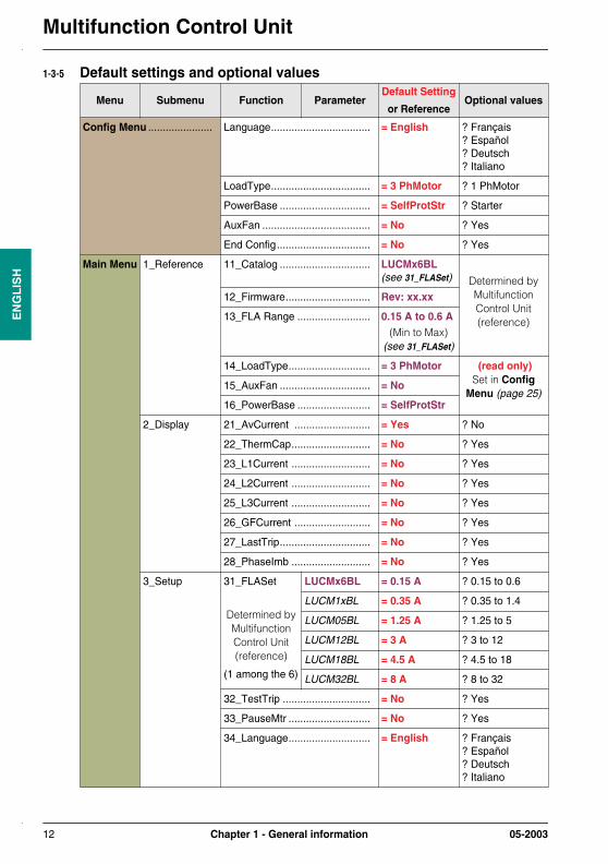
1-3-5 Default settings and optional values
Menu Submenu Function ParameterDefault Setting
or ReferenceOptional values
Config Menu ...................... Language.................................. = English ? Français? Español? Deutsch? Italiano
LoadType.................................. = 3 PhMotor ? 1 PhMotor
PowerBase ............................... = SelfProtStr ? Starter
AuxFan ..................................... = No ? Yes
End Config................................ = No ? Yes
Main Menu 1_Reference 11_Catalog ............................... LUCMx6BL(see 31_FLASet) Determined by
Multifunction Control Unit (reference)
12_Firmware............................. Rev: xx.xx
13_FLA Range ......................... 0.15 A to 0.6 A(Min to Max)
(see 31_FLASet)
14_LoadType............................ = 3 PhMotor (read only)Set in Config
Menu (page 25)15_AuxFan ............................... = No
16_PowerBase ......................... = SelfProtStr
2_Display 21_AvCurrent .......................... = Yes ? No
22_ThermCap........................... = No ? Yes
23_L1Current ........................... = No ? Yes
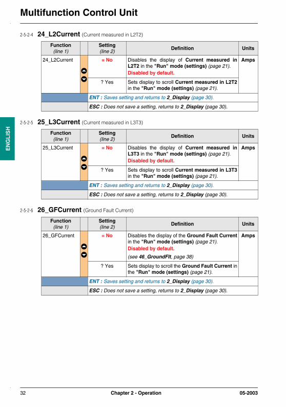
24_L2Current ........................... = No ? Yes
25_L3Current ........................... = No ? Yes
26_GFCurrent .......................... = No ? Yes
27_LastTrip............................... = No ? Yes
28_PhaseImb ........................... = No ? Yes
3_Setup 31_FLASet
Determined by Multifunction Control Unit (reference)
(1 among the 6)
LUCMx6BL = 0.15 A ? 0.15 to 0.6
LUCM1xBL = 0.35 A ? 0.35 to 1.4
LUCM05BL = 1.25 A ? 1.25 to 5
LUCM12BL = 3 A ? 3 to 12
LUCM18BL = 4.5 A ? 4.5 to 18
LUCM32BL = 8 A ? 8 to 32
32_TestTrip .............................. = No ? Yes
33_PauseMtr ............................ = No ? Yes
34_Language............................ = English ? Français? Español? Deutsch? Italiano
12 Chapter 1 - General information 05-2003

Multifunction Control Unit
EN
GL
ISH
(Main Menu) 4_AdvSetup 41_TripClass ............................ = 5 ? 5 to 30
42_ResetMode ......................... = Manual ? Remote/Ent? Auto
43_RstAdjust ResetTime = 120 Sec. ? 1 to 1000
ResetLevel = 80% (Capacity)
? 35 to 100
44_MagTrip .............................. = 1420% FLA ? 300 to 1700
45_OLWarning Warning = On ? Off
Warn Level = 85% (Capacity)
? 10 to 100
46_GroundFlt Trip = On ? Off
TripTime = 1.0 Sec. ? 0.1 to 1.2
TripLevel = x A (30% FLA min)
? 20 to 500
Warning = On ? Off
Warn Level = x A (30% FLA min)
? 20 to 500
47_PhaseImb Trip = On ? Off
TripTimeStrt = 0.7 Sec. ? 0.2 to 20
TripTimeRun = 5.0 Sec. ? 0.2 to 20
TripLevel = 10% IMB ? 10 to 30
Warning = On ? Off
Warn Level = 10% IMB ? 10 to 30
48_Jam Trip = Off ? On
TripTime = 5 Sec. ? 1 to 30
TripLevel = 200% FLA ? 100 to 800
Warning = Off ? On
Warn Level = 200% FLA ? 100 to 800
49_UnderLoad Trip = Off ? On
TripTime = 10 Sec. ? 1 to 200
TripLevel = 50% FLA ? 30 to 100
Warning = Off ? On
Warn Level = 50% FLA ? 30 to 100
410_LongStrt Trip = Off ? On
TripTime = 10 Sec. ? 1 to 200
TripLevel = 100% FLA ? 100 to 800
Warning = Off ? On
Warn Level = 100% FLA ? 100 to 800
Menu Submenu Function ParameterDefault Setting
or ReferenceOptional values
05-2003 Chapter 1 - General information 13
Multifunction Control UnitE
NG
LIS
H
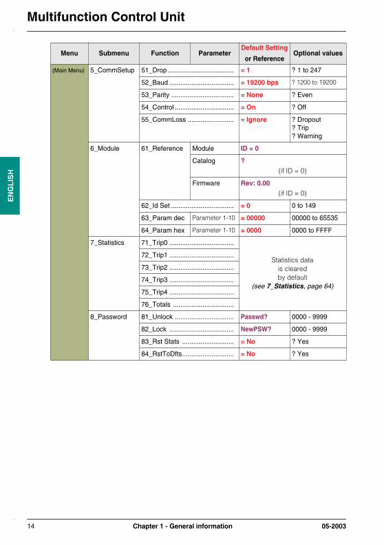
(Main Menu) 5_CommSetup 51_Drop.................................... = 1 ? 1 to 247
52_Baud ................................... = 19200 bps ? 1200 to 19200
53_Parity .................................. = None ? Even
54_Control ................................ = On ? Off
55_CommLoss ......................... = Ignore ? Dropout? Trip? Warning
6_Module 61_Reference Module ID = 0
Catalog ? (if ID = 0)
Firmware Rev: 0.00 (if ID = 0)
62_Id Set .................................. = 0 0 to 149
63_Param dec Parameter 1-10 = 00000 00000 to 65535
64_Param hex Parameter 1-10 = 0000 0000 to FFFF
7_Statistics 71_Trip0 ...................................
Statistics datais cleared by default
(see 7_Statistics, page 64)
72_Trip1 ...................................
73_Trip2 ...................................
74_Trip3 ...................................
75_Trip4 ...................................
76_Totals .................................
8_Password 81_Unlock ................................ Passwd? 0000 - 9999
82_Lock ................................... NewPSW? 0000 - 9999
83_Rst Stats ............................ = No ? Yes
84_RstToDfts............................ = No ? Yes
Menu Submenu Function ParameterDefault Setting
or ReferenceOptional values
14 Chapter 1 - General information 05-2003

Multifunction Control Unit
EN
GL
ISH
1-3-6 Specifications
1-3-6-1 Environment
(1) Only applicable when power cabling to Power Base exceeds the following sizes: 1,5 mm2 (16 AWG)fitted with cable end or 2.5 mm2 (14 AWG) not fitted with cable end.
(2) Conforms to IEC 1000-4-6 when 46_GroundFlt + TripLevel is set < 50% FLA minimum.
(3) Conforms to IEC 1000-4-6 when 46_GroundFlt + TripLevel is set > 50% FLA minimum.
Conforming to standards IEC 947-4-1, IEC 34-11, IEC 755, VDE 0106, VDE 0660
European community directives
marking. Meets the essential requirements of low Voltage equipment (LV) & Electromagnetic Compatibility (EMC)
Approvals UL 508, CSA, PTB
Protective treatment "TH" (Tropical Finish)
Degree of protection Conforming to IEC 947-1 IP 20(1)
Pollution degree Conforming to IEC 664 3
Shock resistance Conforming to IEC 68-2-27 10g open, 15g closed, 11 milliseconds
Vibration resistance Conforming to IEC 68-2-6 2g open, 4g closed, 5 to 150 Hz
Ambient air temperature around the device
Storage °C°F
- 35 to + 85- 31 to + 185
Operation °C -20 to +60°F -4 to +140
(see 1-3-2, Operating temperatures, page 10 for derating considerations)
Flame resistance Conforming to UL 94 V2
Maximum operating altitude mft
20006562
Operating position In relation to normal vertical mounting plane
Horizontal or vertical 30° angle front or back
Electromagnetic compatibilityElectrostatic discharge
Conforming to IEC 1000-4-2 level 3
kV 8
Electromagnetic compatibilityElectromagnetic field
Conforming to IEC 1000-4-3 level 3
V/m 10
Electromagnetic compatibilityFast transient burst
Conforming to IEC 1000-4-4 level 4
kV 4
Electromagnetic compatibilitySurge immunity
Conforming to IEC 1000-4-5 Common mode Serial mode
Level 4 (Power circuit) kV 6 4
Level 1 (Control circuit) kV 1 0.5
Level 2 (Communication circuit) kV 1 1
Electromagnetic compatibilityConducted disturbances
Conforming to IEC 1000-4-6 level 3
V 3(2)
10(3)
Rated undissipated pulse withstand (U imp)
Conforming to IEC 947-1 kV 2
Resistance to low frequency disturbances - supply harmonics
Conforming to IEC 947-2 Appendix F Clause F4.1
Resistance to micro-breaks Conforming to IEC 1000-4-11
05-2003 Chapter 1 - General information 15

Multifunction Control UnitE
NG
LIS
H
1-3-6-2 Power circuit
(4) For use with 110 to 690 V, 50/60 Hz AC motors only. Not approved for use with DC motors.- Approved for use upstream of variable frequency drives.- Not approved for use downstream of variable frequency drives
1-3-6-3 Control circuit supply (A1, A2 terminals and auxiliary power input)
Operating voltage range V 110 to 690 VAC
Rated insulation voltage (Ui)
Conforming to IEC 947-1 V 690 VAC
Operating frequency(2) Hz 47-63
Rated operational current
LUCMx6BL
LUCM1xBL
LUCM05BL
LUCM12BL
LUCM18BL
LUCM32BL
...........................................
...........................................
...........................................
...........................................
...........................................
...........................................
A0.15 to 0.6
0.35 to 1.4
1.25 to 5
3 to 12
4.5 to 18
8 to 32
Operating voltage V 20.4 to 31.2 VDC
Rated insulation voltage (Ui) Conforming to IEC 947-1 V 380 VAC
Cabling (aux. power only)- Solid or stranded cable .......... 1 conductor mm2
AWG0.5 to 120 to 18
- Stranded cable with cable end.......................
1 conductor mm2
AWG0.5 to 120 to 18
- Solid cable............................ 2 conductors mm2
AWG0.2 to 124 to 18
- Stranded cable...................... 2 conductors mm2
AWG0.2 to 1.520 to 18
Terminal tightening torque (aux. power only)
N.mlb-in
0.5 to 0.64.6 to 5.6
16 Chapter 1 - General information 05-2003

Multifunction Control Unit
EN
GL
ISH
1-3-6-4 RS 485 Serial port RJ-45 connector
Electrical Interface RS 485
Connector RJ-45
RJ-45 pin-out•
Isolation V 1 kV
Max. line length m (ft) 1000 m (3280 ft)
max. tap-off length m (ft) 20 m (65 ft)
Parity None - 1 start bit, 8 data bits and 1 stop bit (10 bits total Default)
Even - 1 start bit, 8 data bits, even parity and 1 stop bit (11 bits total)
Modbus® RTU commands The Multifunction Control Units shall support the following Modbus® RTUcommands:- Code 3 (03 hex) - Normal read holding registers (maximum 100 registers)- Code 6 (06 hex) - Preset (write) single register- Code 16 (10 hex) - Preset (write) multiple registers (maximum count = 46)- Code 65 (41 hex) - Private identification request (specific for drives)
The Multifunction Control Units shall support the following Modbus® RTUreponses:- Code 3 (03 hex) - Normal read holding registers reponse- Code 6 (06 hex) - Normal preset (write) single register reponse- Code 16 (10 hex) - Normal preset (write) multiple registers reponse- Code 65 (41 hex) - Private identification reponse
(data specific for drives: { 0x01, ’-’, 0x01, ’-’, ’B’, ’2’, ’B’, ’2’, ’B’, ’2’, ’B’, ’2’, ’B’, ’2’, ’X’, ’w’, 0x28, 0x01, 0x00} )
The Multifunction Control Units shall support the following Modbus® RTUcodes:- Code 01 - Illegal function- Code 02 - Illegal data address- Code 03 - Illegal data value (write command not completed)
The 54_Control (Write Control) (page 59) enable feature can be used toenable (On) or disable (Off) write privilege to the Multifunction ControlUnits configuration registers. If 54_Control (Write Control) (page 59) is(No), write commands are restricted to the following list of " - alwaysenabled - " registers:- Remote keypad (register 1100)- Multifunction Control Units state control (register 704)- Multifunction Control Units extended state control (register 705)- Option module configuration (registers 680-690)- Private registers above 20000
1
8
D(A)5
(cable connector top view)
D(B)4
+ 5 V7
common8
05-2003 Chapter 1 - General information 17

Multifunction Control UnitE
NG
LIS
H
Chapter 2 - Operation2-1 Menu structure
• Config Menu (Configuration Menu) (page 25) contains equipment specific settings not considered adjustable after initial configuration.
• Main Menu (page 28) contains application specific settings and parameters considered adjustable.
Allows user to exit"Config" menu.
Allows selection ofpower base type used.
Contains product references “Config” settings.
ConfigLanguage
ConfigLoadType
ConfigPowerBase
ConfigAuxFan
ConfigEndConfig
MainMenu1_Reference
MainMenu2_Display
MainMenu3_SetUp
MainMenu4_AdvSetUp
MainMenu5_CommSetUp
MainMenu6_Module
MainMenu7_Statistics
MainMenu8_Password
Allows selection of items displayed during "Run" mode.
Contains basic settings accessible during "Run" mode.
Contains advanced settings accessible during "Off" mode.
Contains settings for RS-485 Modbus© communication port.
Allows configuration ofoptional modules.
Contains stored "Fault" and "Run" informations.
Allows password enabling and module resets for
settings and statistics.
1_Reference11_Catalog
(==> 84_RstToDfts)
2_Display21_AvCurrent
3_SetUp31_FLASet
4_AdvSetUp41_Trip Class
5_CommSetUp51_Drop
6_Module61_Reference
7_Statistics71_Trip0
8_Password81_Unlock- - - 84_RstToDfts 84_RstToDfts
= No? Yes
Language= English
LoadType= 3 Ph Motor
PowerBase= SelfProtStr
AuxFan= No
EndConfig= No? Yes
Allows selection ofdisplay languages.
Allows selection of single or 3-phase motor protection.
Allows selection of thermal protection for fan cooled motors.
Off Firstpower-up
Subsequentpower-ups
(see 2-2-2, p. 20) (see 2-2-1, p. 19)
18 Chapter 2 - Operation 05-2003
Multifunction Control Unit
EN
GL
ISH
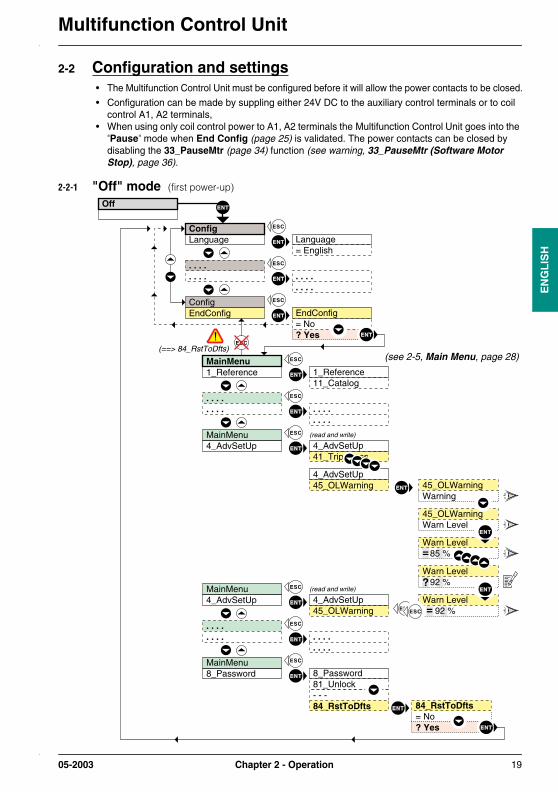
2-2 Configuration and settings• The Multifunction Control Unit must be configured before it will allow the power contacts to be closed.
• Configuration can be made by suppling either 24V DC to the auxiliary control terminals or to coil control A1, A2 terminals,
• When using only coil control power to A1, A2 terminals the Multifunction Control Unit goes into the "Pause" mode when End Config (page 25) is validated. The power contacts can be closed by disabling the 33_PauseMtr (page 34) function (see warning, 33_PauseMtr (Software Motor Stop), page 36).
2-2-1 "Off" mode (first power-up)
45_OLWarningWarning
4_AdvSetUp41_Trip Class
4_AdvSetUp45_OLWarning
Off
ConfigLanguage
. . . .
. . . .
. . . .
. . . .
ConfigEndConfig
. . . .
. . . .
Language= English
. . . .
. . . .
. . . .
. . . .
MainMenu1_Reference 1_Reference
11_Catalog
(==> 84_RstToDfts)
EndConfig= No? Yes
=
=
Warn Level 92 %
?
Warn Level 85 %
Warn Level 92 %
(read and write)MainMenu4_AdvSetUp
4_AdvSetUp45_OLWarning
. . . .
. . . .
(read and write)MainMenu4_AdvSetUp
45_OLWarningWarn Level
MainMenu8_Password 8_Password
81_Unlock- - - 84_RstToDfts 84_RstToDfts
= No? Yes
(see 2-5, Main Menu, page 28)
05-2003 Chapter 2 - Operation 19

Multifunction Control UnitE
NG
LIS
H
2-2-2 "Off" mode (subsequent power-ups)
• Main Menu (page 28) settings can be modified by applying auxiliary control power or by initiating the 33_PauseMtr (page 34) function and opening the main power contacts while coil control power is applied to A1, A2 terminals.
• Should it be necessary to re-enter the Config Menu (Configuration Menu) (page 25) and change a configure setting, the user must first validade the 84_RstToDfts (page 68) function. This resets all parameters back to factory default settings.
MainMenu1_Reference
or
=>
MainMenu2_Display
MainMenu3_SetUp
MainMenu5_CommSetUp
MainMenu6_Module
MainMenu7_Statistics
MainMenu8_Password
1_Reference11_Catalog
(read only)
(read and write)
(read and write)
(read and write)
(read and write)
(read only)
(read and write)
2_Display21_AvCurrent
3_SetUp31_FLASet
5_CommSetUp51_Drop
6_Module61_Reference
7_Statistics71_Trip0
8_Password81_Unlock
During "Off" mode"2_Display" parameters are read and write
During "Off" mode "1_Reference" parameters are read only
Indicates main contacts are open and no power detected at A1, A2 terminals.
for5 sec.
If key is not touched
During "Off" mode "5_CommSetUp" parameters are read and write
During "Off" mode "6_Module" parameters are read and write
During "Off" mode "7_Statistics" parameters are read only
During "Off" mode "8_Password" parameters are read and write
=> Indicates main contacts are open with power detected at A1, A2 terminals.
Off
Off - Pause
45_OLWarningWarning
4_AdvSetUp41_Trip Class
4_AdvSetUp45_OLWarning
=
=
Warn Level 92 %
?
Warn Level 85 %
Warn Level 92 %
(read and write)MainMenu4_AdvSetUp
4_AdvSetUp45_OLWarning
(read and write)MainMenu4_AdvSetUp
45_OLWarningWarn Level
During "Off" mode"3_SetUp" parameters are read and write
During "Off" mode"4_AdvSetUp" parameters are read and write
(see warning, 33_PauseMtr (Software Motor Stop), page 36)
20 Chapter 2 - Operation 05-2003

Multifunction Control Unit
EN
GL
ISH
2-2-3 "Run" mode (settings)
• Line 1 of the display shows "Run" when the Power Base main contacts are closed.
• Line 2 of the display can be set to scroll certain information for monitoring (see 2-5-2, 2_Display, page 30).
• Only functions 2_Display (page 30) and 3_Setup (page 34) can be modified when theMultifunction Control Unit is in the "Run" mode.
(read and write)
3_SetUp31_FLASet
=31_FLASet 2.9A
MainMenu1_Reference
MainMenu2_Display
MainMenu3_SetUp
MainMenu4_AdvSetUp
MainMenu3_SetUp
MainMenu5_CommSetUp
MainMenu6_Module
MainMenu7_Statistics
MainMenu8_Password
1_Reference11_Catalog
(read only)
(read and write)
(read and write)
(read only)
(read only)
(read only)
(read only)
(read only)
2_Display21_AvCurrent
3_SetUp31_FLASet
4_AdvSetUp41_Trip Class
5_CommSetUp51_Drop
6_Module61_Reference
7_Statistics71_Trip0
8_Password81_Unlock
During "Run" mode"3_SetUp" parameters are read and write
During "Run" mode"2_Display" parameters are read and write
During "Run" mode "1_Reference" parameters are read only
=
?
31_FLASet 2.5A
31_FLASet 2.9A
after2 sec.
for5 sec.
If key is not touched
During "Run" mode "4_AdvSetUp" parameters are read only
During "Run" mode "5_CommSetUp" parameters are read only
During "Run" mode "6_Module" parameters are read only
During "Run" mode "7_Statistics" parameters are read only
During "Run" mode "8_Password" parameters are read only
RunIAV=2.5A
RunTherm=65%
RunIL1=2.5A
RunImbal=1.0A
RunIL2=3.5A
RunIL3=3.5A
RunIGR=0.2A
RunLT : Over-Load
Power-up
(if more than one item selected)
Scrolling Run infodisplay
(21_AvCurrent = Average 3 phase current)
(22_ThermCap = Thermal capacity)
(23_L1Current = Phase 1 current)
(24_L2Current = Phase 2 current)
(28_PhaseImb = Phase imbalance)
(27_LastTrip = Last trip type)
(26_GFCurrent = Ground fault current)
(25_L3Current = Phase 3 current)
05-2003 Chapter 2 - Operation 21
Multifunction Control UnitE
NG
LIS
H
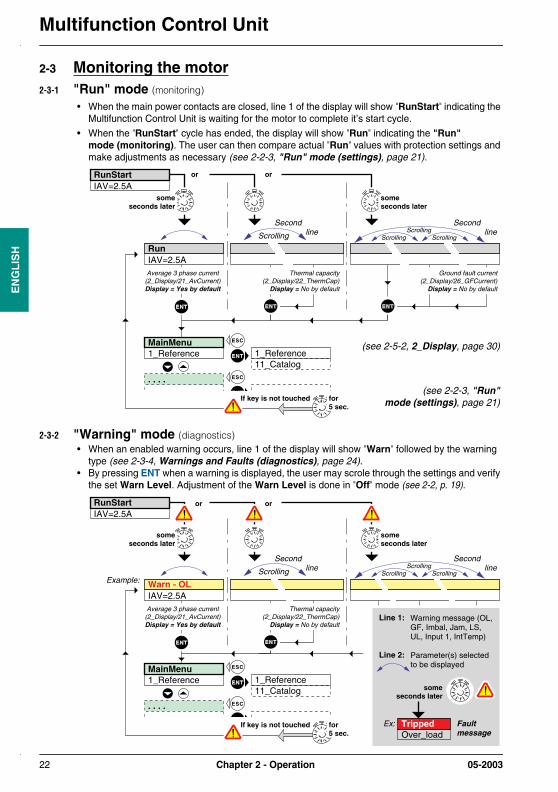
2-3 Monitoring the motor2-3-1 "Run" mode (monitoring)
• When the main power contacts are closed, line 1 of the display will show "RunStart" indicating the Multifunction Control Unit is waiting for the motor to complete it’s start cycle.
• When the "RunStart" cycle has ended, the display will show "Run" indicating the "Run" mode (monitoring). The user can then compare actual "Run" values with protection settings and make adjustments as necessary (see 2-2-3, "Run" mode (settings), page 21).
2-3-2 "Warning" mode (diagnostics)• When an enabled warning occurs, line 1 of the display will show "Warn" followed by the warning
type (see 2-3-4, Warnings and Faults (diagnostics), page 24).• By pressing ENT when a warning is displayed, the user may scrole through the settings and verify
the set Warn Level. Adjustment of the Warn Level is done in "Off" mode (see 2-2, p. 19).
RunIAV=2.5A
someseconds later
RunStartIAV=2.5A
someseconds later
or or
MainMenu1_Reference 1_Reference
11_Catalog
Scrolling
Second line
Second line
Scrolling ScrollingScrolling
. . . .
Average 3 phase current(2_Display/21_AvCurrent)Display = Yes by default
Thermal capacity(2_Display/22_ThermCap)
Display = No by default
Ground fault current(2_Display/26_GFCurrent)
Display = No by default
for5 sec.
If key is not touched
(see 2-5-2, 2_Display, page 30)
(see 2-2-3, "Run"mode (settings), page 21)
Warn - OLIAV=2.5A
someseconds later
RunStartIAV=2.5A
someseconds later
or or
MainMenu1_Reference 1_Reference
11_Catalog
Example:Scrolling Scrolling
ScrollingScrolling
. . . .
Second line
Second line
Line 1:
Line 2:
Warning message (OL, GF, Imbal, Jam, LS, UL, Input 1, IntTemp)
Parameter(s) selected to be displayed
someseconds later
TrippedOver_load
Faultmessage
Ex:
Average 3 phase current(2_Display/21_AvCurrent)Display = Yes by default
for5 sec.
If key is not touched
Thermal capacity(2_Display/22_ThermCap)
Display = No by default
22 Chapter 2 - Operation 05-2003

Multifunction Control Unit
EN
GL
ISH
2-3-3 "Fault" mode (diagnostics)
• Detected faults will either trip the base mechanism or open the power contacts depending on thefault type (see 2-3-4, Warnings and Faults (diagnostics), page 24) and reset mode selected(see , 42_ResetMode, page 40).
• Faults that trip the base mechanism will show "Tripped" in the line 1 of the display and the faulttype in the line 2. A Manual Reset will be required before a restart can be made.
• Faults that open the power contacts will show "Off-Fault Type" in line 1 of the display and"Ent to Reset" in line 2. Reset can be made by pressing the ENT key or sending a remote resetsignal via the RS 485 communication port or by an optional module. "Over_load" and "Test Trip"faults will show "Wait" and the delay in seconds before "Ent to Reset" appears.
NOTE: Resetting "Off-" faults will automatically start the motor if coil control power is still appliedto A1, A2 terminals.Tripped fault types can not be displayed without auxiliary control power.
• Faults that show "Int Trip" in line 1 of the display and Fault type code in line 2, indicate internalFaults detected by the Multifunction Control Unit. A Manual Reset and cycling of the auxilliarycontrol power from On to Off will be required before a Restart can be made.
someseconds later
RunStartIAV=3.0A
or
MainMenu1_Reference 1_Reference
11_Catalog
for5 sec.
If key is not touched
someseconds later
Fault messageExample:
If the "Warning" is disabled
If the "Warning" is disabled
MainMenu7_Statistics
(read only)
7_Statistics71_Trip0
During "Run" mode "7_Statistics" parameters are read only
. . . .
. . . . . . . .. . . .
During "Run" mode "1_Reference" parameters are read only
(read only)
RunIAV=2.5A
or
someseconds later
Warn - . . .IAV=2.5A
TrippedOver_load
(see 2-3-4, Warnings andFaults (diagnostics), page 24)
(see 2-5-7, 7_Statistics, page 64)
05-2003 Chapter 2 - Operation 23

Multifunction Control UnitE
NG
LIS
H
2-3-4 Warnings and Faults (diagnostics)
EE Prom checksum"EEROM Error"
Internal Fault TypeFault Code Internal Fault TypeFault Code
ROM (flash) check51 57
Asic read-after-write52
Asic initialize check53
54
55
Coil control and Asic watchdog
Stack Overflow check
RAM check56
Hardware Watchdog58
Current detected while OFF59
(L2 current) detected in 1-Phase Mode60
Base trip not detected61
Control overvoltage63
Multifunction Control Unit Internal Temperature
Control wiring fault62
See option module instruction material for fault codes.
Mxxx :* indicates Warning, Dropout or Fault code. See option module instruction manual for Fault code identification.
Warn-Int Temp
Warn-Mxxx
Warn-Comm
Warning or Fault Type
Warningmessage
Fault Message"Manual" Mode "Remote/Ent" Mode
Type Warning Mode Trip Mode Dropout Mode
"Auto" Mode
Thermal Overload
Short circuit Fault
Shunt trip Fault
Magnetic Fault
Ground Fault
Phase Imbalance Fault
Option Module Fault *
Jam Fault
Long Start Fault
Internal temperatureFault
Lost CommunicationsFault
Under Load Fault
Warn-OL
Line 1
Line 2
TrippedOver_Load
Off-OLWait xxx (Secs)
Off-OLAuto xxx (Secs)
TrippedShort
TrippedShort
TrippedShort
TrippedShunt
TrippedShunt
TrippedMagTrip
TrippedMagTrip
TrippedMagTrip
Warn-GF TrippedGround Fault
TrippedGround Fault
TrippedGround Fault
Warn-Imbal TrippedPhasImb
Off-ImbalEnt to Reset
Off-ImbalEnt to Reset
Warn-Jam TrippedJam
Off-JamEnt to Reset
Off-JamEnt to Reset
Warn-LongSt TrippedLngStrt
Off-LongStEnt to Reset
Off-LongStEnt to Reset
Warn-UndrLd TrippedUnderLoad
Off-UndrLdEnt to Reset
Off-UndrLdEnt to Reset
TrippedShunt
TrippedTestTrp
Off-TestWait xxx (Secs)
Off-TestWait xxx (Secs)
Int Trip51
Int Trip51
Int Trip51
Off-CommEnt to Reset
TrippedMxxx
Off-MxxxEnt to Reset
TrippedCommLoss
Test Trip Fault
Internal Fault(see list below fault type)
Int Trip
**Int Trip
** **Int Trip
(scrolled Run info)
(scrolled Run info)
(scrolled Run info)
(scrolled Run info)
(scrolled Run info)
(scrolled Run info)
(scrolled Run info)
(scrolled Run info)
(scrolled Run info)
(see 1-3-2, Operatingtemperatures, page 10)
24 Chapter 2 - Operation 05-2003

Multifunction Control Unit
EN
GL
ISH
2-4 Config Menu (Configuration Menu)
• The Config Menu (Configuration Menu) is the initial menu displayed by the Multifunction ControlUnit as shipped from the factory.
• It contains the configuration settings that are equipment specific. These settings are not typicallyadjusted after initial configuration.
• To exit the Config Menu (Configuration Menu), you must save the End Config function.
• To access the Config Menu (Configuration Menu) after the End Config is saved, theMultifunction Control Unit must be reset to default factory settings (see 84_RstToDfts, page 68).
• These settings are always viewable in the 1_Reference (page 28) menu.
Menu(line 1)
Function(line 2)
Definition
Config Menu Language
(see 2-4-1, p. 26)
Selects the language used in the Multifunction ControlUnit display.
NOTE: Language type can also be selected in34_Language (page 35).
LoadType
(see 2-4-2, p. 26)
Sets motor protection functions for 3-phase or 1-phase.
NOTE: Selecting the 1-phase setting with 3-phase motors will cause an internal trip 60 indicating 24_L2Current detected in 1-phase mode.
PowerBase
(see 2-4-3, p. 26)
(see CAUTION, page 26)
Identifies the type of Power Base in which theMultifunction Control Unit will be installed.
The Power Base type is marked on the side of the base device.
NOTE: This function serves as an identifier only.It does not influence the protection functions,settings or type of protection that the PowerBase provides.
AuxFan
(see 2-4-4, p. 27)
(see CAUTION, page 27)
Sets thermal protection settings for motors cooled byauxiliary fans.
NOTE: When enabled, effective thermal reset time isreduced by a factor of 4. For reset times,See Appendix A - Thermal Trip and Resetcurves (page 72).
End Config
(see 2-4-5, p. 27)
Sets initial configuration and enables the Main Menu(page 28).
NOTE: Once End Config (page 27) is saved, theConfig Menu (Configuration Menu) isaccessed by resetting the device back tofactory default settings (see 84_RstToDfts,page 68).
NOTE: Press or to enable stepping through all the display functions.
ENT : Sends to functions settings.
05-2003 Chapter 2 - Operation 25

Multifunction Control UnitE
NG
LIS
H
2-4-1 Language (Unit Display Language)
2-4-2 LoadType (Motor Load Type)
NOTE: Load Type sets the calculated average current value in the Multifunction Control Unit asfollows:3-Phase Load setting - I Average = (I1 + I2 + I3) / 31-Phase Load setting - I Average = (I1 + I2 + I3) / 2
2-4-3 PowerBase (Motor Starter Power Base Type)
Function(line 1)
Setting(line 2)
Definition
Language = English Sets display to English.Enabled by default.
? Français Sets display to French.
? Español Sets display to Spanish.
? Deutsch Sets display to German.
? Italiano Sets display to Italian.
ENT : Saves setting and returns to Config Menu (page 25).
ESC : Does not save a setting, returns to Config Menu (page 25).
Function(line 1)
Setting(line 2)
Definition
LoadType = 3 PhMotor Sets unit configuration to three phase motor protection.Enabled by default.
? 1 PhMotor Sets unit configuration for single phase motor protection.
ENT : Saves setting and returns to Config Menu (page 25).
ESC : Does not save a setting, returns to Config Menu (page 25)
CAUTIONIncorrect Power Base setting
• Changing the Power Base setting does not affect motor protection functions or current interruptioncapacity of the Power Base,
• Setting incorrect Power Base may cause the wrong Power Base to be read and displayed by the LCDor remote network device.
Incorrect setting of the Power Base function can result in serious injury, or equipmentdamage.
Function(line 1)
Setting(line 2)
Definition
PowerBase = SelfProtStr Sets identification reference for a self-protected motorstarter, which provides both short circuit and overloadprotection for a motor branch circuit.Enabled by default.
? Starter Sets identification reference for a motor starter, whichprovides only overload protection for a motor branch circuit.
ENT : Saves setting and returns to Config Menu (page 25).
ESC : Does not save a setting, returns to Config Menu (page 25)
26 Chapter 2 - Operation 05-2003

Multifunction Control Unit
EN
GL
ISH
2-4-4 AuxFan (Auxiliary Fan Cooled Motor)
2-4-5 End Config (End Configuration Mode)
CAUTIONIncorrect AuxFan setting
• When the AuxFan option is set, the reset (motor cool down) time is reduced by a factor of 4,• If the motor is not equipped with an operating auxiliary cooling fan, the calculated thermal capacity
will be incorrect.
Incorrect setting of the AuxFan function can result in injury, or equipment damage.
Function(line 1)
Setting(line 2)
Definition
AuxFan = No Disables Auxiliary Fan Cooled function setting thermalprotection levels for motors not cooled by auxiliary fans.Disabled by default.
? Yes Enables Auxiliary Fan Cooled function setting thermalprotection levels for motors cooled by auxiliary fans.
ENT : Saves setting and returns to Config Menu (page 25).
ESC : Does not save a setting, returns to Config Menu (page 25).
Function(line 1)
Setting(line 2)
Definition
End Config = No Returns to Config Menu (Configuration Menu) (page 25). Disabled by default.
? Yes Sets initial configuration and sends to Main Menu (p. 28).
ENT : Saves setting.
ESC : Does not save a setting, returns to Config Menu (page 25).
05-2003 Chapter 2 - Operation 27

Multifunction Control UnitE
NG
LIS
H
2-5 Main Menu• The Main Menu is the initial menu displayed after the Multifunction Control Unit has been
configured.
• It contains all the user menus for:- setting protection functions,- configuration of optional communication and I/O modules,- accessing stored statistical information,- setting display characteristics.
Menu(line 1)
Submenu(line 2)
Definition
Main Menu 1_Reference
(see 2-5-1, p. 29)
Displays Multifunction Control Unit references and theConfig Menu (Configuration Menu) (page 25)functions settings.
2_Display
(see 2-5-2, p. 30)
Sets type of information that scrolls on the MultifunctionControl Unit display while in the "Run"mode (monitoring) (page 22).
3_Setup
(see 2-5-3, p. 34)
Provides access to the basic unit protection and setupfunctions.
These are functions that can be set while the unit is inthe "Run" mode (monitoring) (page 22).
4_AdvSetup
(see 2-5-4, p. 37)
Provides access to the advanced protection functions.
5_CommSetup
(see 2-5-5, p. 57)
Provides access to the communication setting of the RS485 external communication port.
6_Module
(see 2-5-6, p. 61)
Provides access to the functions and settings of optionalcommunication and function modules.
7_Statistics
(see 2-5-7, p. 64)
Provides access to historical information data stored inthe unit memory.
Includes information on the last five faults, count totalsand reset data.
8_Password
(see 2-5-8, p. 67)
Provides password protection to prevent unauthorizedchanges to configurable functions.
Also provides access to unit function resets.
NOTE: Press or to enable stepping through all the display Submenus.
ENT : Sends to Submenu.
28 Chapter 2 - Operation 05-2003

Multifunction Control Unit
EN
GL
ISH
2-5-1 1_Reference• The 1_Reference submenu allows READ only access to product references and the functions set
in the Config Menu (Configuration Menu). • They can be viewed in either the "Run" mode (settings) (page 21) or Configuration and
settings (page 19):
MenuSubmenu
(line 1, line 2)
FunctionReference
(line 1, line 2)Definition
(Main Menu)
1_ReferenceENT 11_Catalog
LUCMx6BL-Catalog number is displayedLine 2.
Det
erm
ined
by
Mul
tifun
ctio
n C
ontro
l Uni
t (r
efer
ence
)
12_Firmware
Rev: xx.xx-Firmware revision is displayedLine 2.
13_FLA Range
0.15 A to 0.6 A-Minimum to maximum (Amps) motor current setting range is displayed Line 2. (see 2-5-3-1, 31_FLASet (Full Load Amp Setting), page 35)
14_LoadType
= 3 PhMotor(same setting as § 2-4-2)
(read only)
The Motor Load Type function isdisplayed Line 2.
Set i
n C
onfig
Men
u (C
onfig
urat
ion
Men
u) (p
age
25).
To
mod
ify th
ese
setti
ngs,
it’s
nec
essa
ry to
acc
ess
the
Con
fig M
enu
(Con
figur
atio
n M
enu)
(s
ee 8
4_R
stTo
Dft
s, p
age
68)
15_AuxFan
= No(same setting as § 2-4-4)
(read only)
The Auxiliary Fan Cooled Motorfunction is displayed Line 2.
16_PowerBase
= SelfProtStr(same setting as § 2-4-3)
(read only)
The Motor Starter Power BaseType function is displayed Line 2.
ENT : Sends to functions for viewing.
NOTE: Press or to enable stepping through all the functionreferences.
ESC : Returns to Main Menu (page 28).
05-2003 Chapter 2 - Operation 29
Multifunction Control UnitE
NG
LIS
H
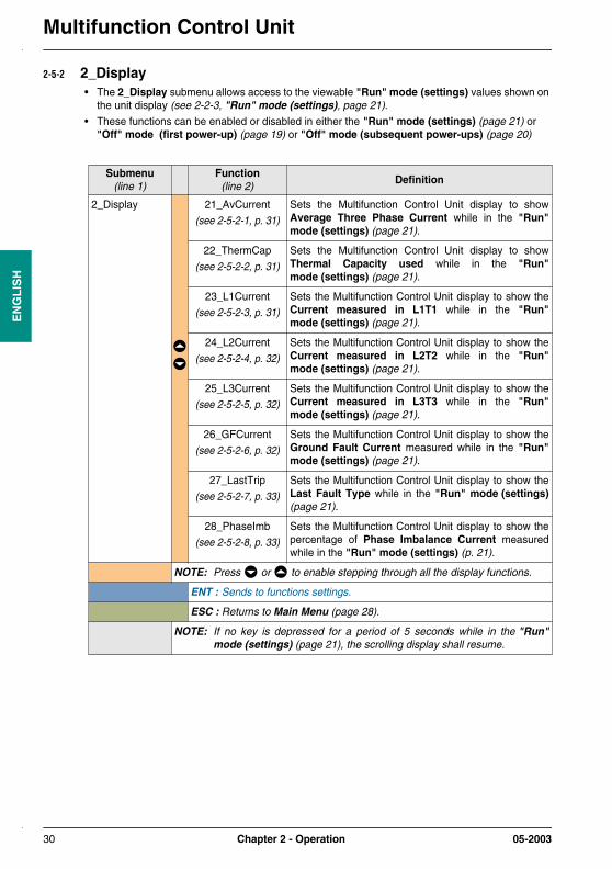
2-5-2 2_Display• The 2_Display submenu allows access to the viewable "Run" mode (settings) values shown on
the unit display (see 2-2-3, "Run" mode (settings), page 21).
• These functions can be enabled or disabled in either the "Run" mode (settings) (page 21) or "Off" mode (first power-up) (page 19) or "Off" mode (subsequent power-ups) (page 20)
Submenu(line 1)
Function(line 2)
Definition
2_Display 21_AvCurrent
(see 2-5-2-1, p. 31)
Sets the Multifunction Control Unit display to showAverage Three Phase Current while in the "Run"mode (settings) (page 21).
22_ThermCap
(see 2-5-2-2, p. 31)
Sets the Multifunction Control Unit display to showThermal Capacity used while in the "Run"mode (settings) (page 21).
23_L1Current
(see 2-5-2-3, p. 31)
Sets the Multifunction Control Unit display to show theCurrent measured in L1T1 while in the "Run"mode (settings) (page 21).
24_L2Current
(see 2-5-2-4, p. 32)
Sets the Multifunction Control Unit display to show theCurrent measured in L2T2 while in the "Run"mode (settings) (page 21).
25_L3Current
(see 2-5-2-5, p. 32)
Sets the Multifunction Control Unit display to show theCurrent measured in L3T3 while in the "Run"mode (settings) (page 21).
26_GFCurrent
(see 2-5-2-6, p. 32)
Sets the Multifunction Control Unit display to show theGround Fault Current measured while in the "Run"mode (settings) (page 21).
27_LastTrip
(see 2-5-2-7, p. 33)
Sets the Multifunction Control Unit display to show theLast Fault Type while in the "Run" mode (settings)(page 21).
28_PhaseImb
(see 2-5-2-8, p. 33)
Sets the Multifunction Control Unit display to show thepercentage of Phase Imbalance Current measuredwhile in the "Run" mode (settings) (p. 21).
NOTE: Press or to enable stepping through all the display functions.
ENT : Sends to functions settings.
ESC : Returns to Main Menu (page 28).
NOTE: If no key is depressed for a period of 5 seconds while in the "Run"mode (settings) (page 21), the scrolling display shall resume.
30 Chapter 2 - Operation 05-2003

Multifunction Control Unit
EN
GL
ISH
2-5-2-1 21_AvCurrent (Average Three Phase Current)
2-5-2-2 22_ThermCap (Thermal Capacity used)
2-5-2-3 23_L1Current (Current measured in L1T1)
Function(line 1)
Setting(line 2)
Definition Units
21_AvCurrent = Yes Sets display to scroll Average Three PhaseCurrent or single-phase current in the "Run"mode (settings) (page 21). Enabled by default.
Amps
? No Disables the display of Average Three PhaseCurrent or single-phase current in the "Run"mode (settings) (page 21).
ENT : Saves setting and returns to 2_Display (page 30).
ESC : .Does not save a setting, returns to 2_Display (page 30)
Function(line 1)
Setting(line 2)
Definition Units
22_ThermCap = No Disables the display of Thermal Capacity used inthe "Run" mode (settings) (page 21).Disabled by default.
%
? Yes Sets display to scroll Thermal Capacity used inthe "Run" mode (settings) (page 21).
ENT : Saves setting and returns to 2_Display (page 30).
ESC : Does not save a setting, returns to 2_Display (page 30).
Function(line 1)
Setting(line 2)
Definition Units
23_L1Current = No Disables the display of Current measured inL1T1 in the "Run" mode (settings) (page 21). Disabled by default.
Amps
? Yes Sets display to scroll Current measured in L1T1in the "Run" mode (settings) (page 21).
ENT : Saves setting and returns to 2_Display (page 30).
ESC : Does not save a setting, returns to 2_Display (page 30).
05-2003 Chapter 2 - Operation 31
Multifunction Control UnitE
NG
LIS
H
2-5-2-4 24_L2Current (Current measured in L2T2)
2-5-2-5 25_L3Current (Current measured in L3T3)
2-5-2-6 26_GFCurrent (Ground Fault Current)
Function(line 1)
Setting(line 2)
Definition Units
24_L2Current = No Disables the display of Current measured inL2T2 in the "Run" mode (settings) (page 21). Disabled by default.
Amps
? Yes Sets display to scroll Current measured in L2T2in the "Run" mode (settings) (page 21).
ENT : Saves setting and returns to 2_Display (page 30).
ESC : Does not save a setting, returns to 2_Display (page 30).
Function(line 1)
Setting(line 2)
Definition Units
25_L3Current = No Disables the display of Current measured inL3T3 in the "Run" mode (settings) (page 21). Disabled by default.
Amps
? Yes Sets display to scroll Current measured in L3T3in the "Run" mode (settings) (page 21).
ENT : Saves setting and returns to 2_Display (page 30).
ESC : Does not save a setting, returns to 2_Display (page 30).
Function(line 1)
Setting(line 2)
Definition Units
26_GFCurrent = No Disables the display of the Ground Fault Currentin the "Run" mode (settings) (page 21). Disabled by default.
(see 46_GroundFlt, page 38)
Amps
? Yes Sets display to scroll the Ground Fault Current inthe "Run" mode (settings) (page 21).
ENT : Saves setting and returns to 2_Display (page 30).
ESC : Does not save a setting, returns to 2_Display (page 30).
32 Chapter 2 - Operation 05-2003

Multifunction Control Unit
EN
GL
ISH
2-5-2-7 27_LastTrip (Last Fault Type)
2-5-2-8 28_PhaseImb (Phase Imbalance Current)
Function(line 1)
Setting(line 2)
Definition Units
27_LastTrip = No Disables the display of the Last Fault Type in the"Run" mode (settings) (page 21).Disabled by default.
-
? Yes Sets display to scroll the Last Fault Type in the"Run" mode (settings) (page 21).
ENT : Saves setting and returns to 2_Display (page 30).
ESC : Does not save a setting, returns to 2_Display (page 30).
Function(line 1)
Setting(line 2)
Definition Units
28_PhaseImb = No Disables the display of the Phase ImbalanceCurrent in the "Run" mode (settings) (page 21). Disabled by default.
%
? Yes Sets display to scroll the percentage of PhaseImbalance Current measured in the "Run"mode (settings) (page 21).
ENT : Saves setting and returns to 2_Display (page 30).
ESC : Does not save a setting, returns to 2_Display (page 30).
05-2003 Chapter 2 - Operation 33

Multifunction Control UnitE
NG
LIS
H
2-5-3 3_Setup• The 3_Setup submenu allows access to basic setup functions.
• These functions can be enabled or disabled in either the "Run" mode (settings) (page 21) or "Off" mode (first power-up) (page 19) or "Off" mode (subsequent power-ups) (page 20).
WARNINGImproper / Inadvertant settings
• Setup values can be modified in "Run" mode (settings) (page 21),
• Values can be set via the network,
• External programming devices must be write enabled,
• Power must be applied to set values,
• Use password to prevent unauthorized changes.
Failure to follow these instructions can result in death, serious injury, or equipmentdamage.
Submenu(line 1)
Function(line 2)
Definition
3_Setup 31_FLASet
(see 2-5-3-1, p. 35)
(see WARNING, page 35)
Sets the thermal overload protection level for a motor.
The Full Load Amp Setting (FLA) corresponds to themaximum steady-state current that a motor canwithstand.The FLAvalue is found on the motor nameplate.
NOTE: This function sets the default levels for allprotection functions based on a percentage ofFull-Load current (% FLA).
32_TestTrip
(see 2-5-3-2, p. 35)
Initiates a Test Thermal Overload Fault.
In "Manual Reset" Mode, the Power Base tripsrequiring a Manual Reset.
Remote and automatic reset modes can also be testedby selecting that type of reset mode. (see 42_ResetMode, page 37).
Restart of a motor after a test trip can only be made after the thermal memory timer has elapsed (120 seconds by default). For thermal memory timer adjustment (see 43_RstAdjust, page 37).
33_PauseMtr
(see 2-5-3-3, p. 36)
(see WARNING, page 36)
Opens the main power contacts by de-energizing thecontactor coil while coil control power is still applied toA1, A2 terminals.
NOTE: Should the Multifunction Control Unit losecontrol power while in the "Pause" mode, it willreturn to the "Pause" mode when control poweris reapplied.
34 Chapter 2 - Operation 05-2003

Multifunction Control Unit
EN
GL
ISH
2-5-3-1 31_FLASet (Full Load Amp Setting)
2-5-3-2 32_TestTrip (Test Thermal Overload Fault)
(3_Setup) 34_Language
(see 2-5-3-4, p. 36)
Selects the Language used in the Multifunction ControlUnit display.
NOTE: Language type is also selected in theConfig Menu (Configuration Menu)(page 25).
NOTE: press or to enable stepping through all the display functions.
ENT : Sends to functions settings.
ESC : Returns to Main Menu (page 28).
NOTE: If no key is depressed for a period of 5 seconds while in the "Run"mode (settings) (page 21), the scrolling display shall resume.
WARNINGIncorrect FLA setting
• The FLA Adjustment must be set to match the Full Load Amp rating of the motor,
• FLA sets default values for other motor protection functions.
Incorrect setting of the FLA function can result in injury, or equipment damage.
Function(line 1)
Setting(line 2)
Definition
31_FLASet Determined by Multifunction Control Unit (reference)(only one among these six references)
Sets desired FullLoad Amperes level.
LUCMx6BL LUCM1xBL LUCM05BL LUCM12BL LUCM18BL LUCM32BL
= 0.15 Ato
? 0.6 A
= 0.35 Ato
? 1.4 A
= 1.25 Ato
? 5 A
= 3 Ato
? 12 A
= 4.5 Ato
? 18 A
= 8 Ato
? 32 A
Minto
Max
Minimum settingis Enabled bydefault.
NOTE: press or to increment from the Min. value to the Max. value.
ENT : Saves setting and returns to 3_Setup (page 34).
ESC : Does not save a setting, returns to 3_Setup (page 34).
Function(line 1)
Setting(line 2)
Definition
32_TestTrip = No Disables the Test Trip function. Disabled by default.
? Yes Initiates a Test Trip.
ENT : Saves setting and returns to 3_Setup (page 34).
ESC : Does not save a setting, returns to 3_Setup (page 34).
Submenu(line 1)
Function(line 2)
Definition
05-2003 Chapter 2 - Operation 35

Multifunction Control UnitE
NG
LIS
H
2-5-3-3 33_PauseMtr (Software Motor Stop)
2-5-3-4 34_Language (Unit Display Language) .
WARNINGUnintended motor starting
• The PauseMtr function should never be used in place of a Stop or Off command,• Equipment operation must conform with national and local safety regulations and codes.
Failure to follow these instructions can result in death, serious injury, or equipmentdamage.
Function(line 1)
Setting(line 2)
Definition
33_PauseMtr = No Allows closing of the main power contacts by energizing thecoil with coil control power already applied to A1, A2terminals. Disabled by default.
? Yes Opens the main power contacts by de-energizing thecontactor coil with coil control power still applied to A1, A2terminals.
ENT : Saves setting and returns to 3_Setup (page 34).
ESC : Does not save a setting, returns to 3_Setup (page 34).
Function(line 1)
Setting(line 2)
Definition
34_Language = English Sets display to English.Enabled by default.
? Français Sets display to French.
? Español Sets display to Spanish.
? Deutsch Sets display to German.
? Italiano Sets display to Italian.
ENT : Saves setting and returns to 3_Setup (page 34).
ESC : Does not save a setting, returns to 3_Setup (page 34).
36 Chapter 2 - Operation 05-2003
Multifunction Control Unit
EN
GL
ISH
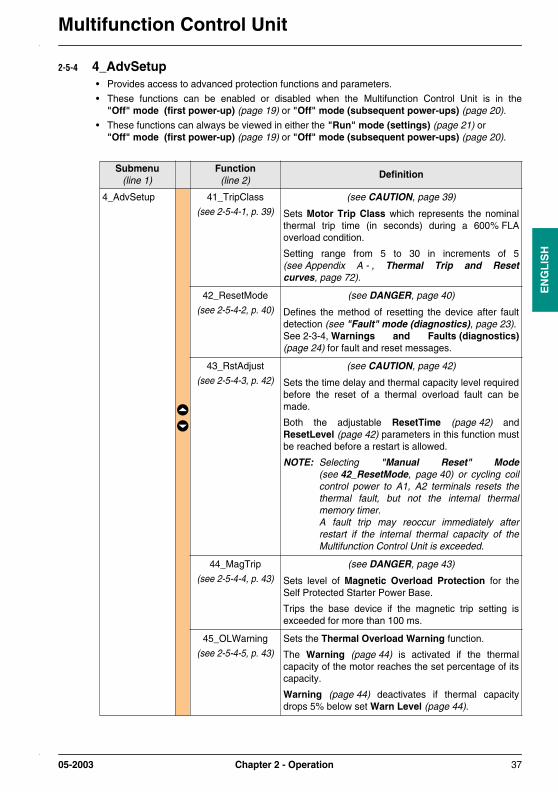
2-5-4 4_AdvSetup• Provides access to advanced protection functions and parameters.
• These functions can be enabled or disabled when the Multifunction Control Unit is in the"Off" mode (first power-up) (page 19) or "Off" mode (subsequent power-ups) (page 20).
• These functions can always be viewed in either the "Run" mode (settings) (page 21) or "Off" mode (first power-up) (page 19) or "Off" mode (subsequent power-ups) (page 20).
Submenu(line 1)
Function(line 2)
Definition
4_AdvSetup 41_TripClass
(see 2-5-4-1, p. 39)
(see CAUTION, page 39)
Sets Motor Trip Class which represents the nominalthermal trip time (in seconds) during a 600% FLAoverload condition.
Setting range from 5 to 30 in increments of 5(see Appendix A - , Thermal Trip and Resetcurves, page 72).
42_ResetMode
(see 2-5-4-2, p. 40)
(see DANGER, page 40)
Defines the method of resetting the device after faultdetection (see "Fault" mode (diagnostics), page 23).See 2-3-4, Warnings and Faults (diagnostics)(page 24) for fault and reset messages.
43_RstAdjust
(see 2-5-4-3, p. 42)
(see CAUTION, page 42)
Sets the time delay and thermal capacity level requiredbefore the reset of a thermal overload fault can bemade.
Both the adjustable ResetTime (page 42) andResetLevel (page 42) parameters in this function mustbe reached before a restart is allowed.
NOTE: Selecting "Manual Reset" Mode(see 42_ResetMode, page 40) or cycling coilcontrol power to A1, A2 terminals resets thethermal fault, but not the internal thermalmemory timer. A fault trip may reoccur immediately afterrestart if the internal thermal capacity of theMultifunction Control Unit is exceeded.
44_MagTrip
(see 2-5-4-4, p. 43)
(see DANGER, page 43)
Sets level of Magnetic Overload Protection for theSelf Protected Starter Power Base.
Trips the base device if the magnetic trip setting isexceeded for more than 100 ms.
45_OLWarning
(see 2-5-4-5, p. 43)
Sets the Thermal Overload Warning function.
The Warning (page 44) is activated if the thermalcapacity of the motor reaches the set percentage of itscapacity.
Warning (page 44) deactivates if thermal capacitydrops 5% below set Warn Level (page 44).
05-2003 Chapter 2 - Operation 37

Multifunction Control UnitE
NG
LIS
H
(4_AdvSetup) 46_GroundFlt
(see 2-5-4-6, p. 45)
(see DANGER, page 45)
Sets the Ground Fault Protection function.
Trip (page 46) parameters can be set for groundcurrents that exceed a set TripLevel (page 47) for a setTripTime (page 46) delay.
Warning (page 47) parameters can be set for groundcurrents that exceed a set Warn Level (page 47).
47_PhaseImb
(see 2-5-4-7, p. 48)
(see WARNING, page 48)
Sets the Phase Imbalance / Phase Loss Protectionfunction.
Trip (page 49) parameters can be set for currents thatdiffer in one phase by more than a set percentage fromthe average current in all three phases for a set timeperiod.
Different time delays can be set for motor startupTripTimeStrt (p. 49) and for normal run TripTimeRun(page 50) conditions.
Warning (page 50) parameter can be set for imbalance/ loss currents that exceed a set Warn Level (page 50).
NOTE: The Phase Imbalance / Phase LossProtection function is automatically disabled ifMultifunction Control Unit is configured forsingle-phase motor loads (see LoadType,page 26).
48_Jam
(see 2-5-4-8, p. 51)
Sets the Jam Protection function.
Trip (page 51) parameters can be set for RMS currentthat exceed a set TripLevel (page 52) for a setTripTime (page 52) period after the Run Start Cycle(page 70) has ended.
Warning (page 52) parameter can be set for jamcurrents that exceed a set Warn Level (page 52).
NOTE: For configuration of the Run Start Cycle time,see 410_LongStrt (page 39).
49_UnderLoad
(see 2-5-4-9, p. 53)
Sets the Under Load Protection.
Trip (page 53) parameter can be set for RMS currentsthat fall below a set TripLevel (page 54) for a setTripTime (page 54) period after the Run Start Cycle(page 70) has ended.
Warning (page 54) parameters can be set forUnderload currents that fall below a set Warn Level(page 54).
NOTE: For configuration of the Run Start Cycle(page 70) time, see 410_LongStrt (page 39).
Submenu(line 1)
Function(line 2)
Definition
38 Chapter 2 - Operation 05-2003

Multifunction Control Unit
EN
GL
ISH
2-5-4-1 41_TripClass (Motor Trip Class)
(4_AdvSetup) 410_LongStrt
(see 2-5-4-10, p. 55)
Sets the Long Start Protection function.
Trip (page 55) parameters can be set for RMS currentsthat exceed a set TripLevel (page 56) after a set RunStart Cycle (page 70) time has ended.
Warning (page 56) parameters can be set for LongStart currents that exceed a set Warn Level (page 56).
NOTE: The Run Start Cycle is defined as the period oftime allowed for a motor to obtain its normal fullload current level after power is applied to theA1, A2 terminals.
For more information, see Run Start Cycle (page 70).
NOTE: Press or to enable stepping through all the display functions.
ENT : Sends to functions settings.
ESC : Returns to Main Menu (page 28).
NOTE: If no key is depressed for a period of 5 seconds while in the "Run"mode (settings) (page 21), the scrolling display shall resume.
CAUTIONIncorrect Trip Class setting
• The Trip Class Adjustment must be set to match the thermal heating characteristics of themotor.
Incorrect setting of the Trip Class function can result in equipment damage.
Function(line 1)
Setting(line 2)
Definition
41_TripClass = 5 Sets trip time to 5 seconds for an overload of 600% FLA. Enabled by default.
? 10 Sets trip time to 10 seconds for an overload of 600% FLA.
? 15 Sets trip time to 15 seconds for an overload of 600% FLA.
? 20 Sets trip time to 20 seconds for an overload of 600% FLA.
? 25 Sets trip time to 25 seconds for an overload of 600% FLA.
? 30 Sets trip time to 30 seconds for an overload of 600% FLA.
ENT : Saves setting and returns to 4_AdvSetup (page 37).
ESC : Does not save a setting, returns to 4_AdvSetup (page 37).
Submenu(line 1)
Function(line 2)
Definition
05-2003 Chapter 2 - Operation 39

Multifunction Control UnitE
NG
LIS
H
2-5-4-2 42_ResetMode (Fault Reset Mode)
DANGERUnintended motor starting
• If A1, A2 power is present and Automatic Reset is selected, the motor will start running afterthe thermal reset timing period,
• Equipment operation must conform with national and local safety regulations and codes.
Failure to follow these instructions will result in death, serious injury, or equipmentdamage.
Function(line 1)
Setting(line 2)
Definition
42_ResetMode = Manual Sets the Multifunction Control Unit to trip the Power Basedevice if an enable fault condition is detected.
A Manual Reset of the Power Base is required before arestart can be made. Enabled by default.
NOTE: In "Manual Reset" Mode, the thermal ResetTime(page 42) and ResetLevel (page 42) functionshave no effect on Thermal Overload Reset Delay.The internal thermal memory function is enabled,and a fault trip may occur immediately after restartif the internal thermal capacity of the MultifunctionControl Unit is exceeded.
? Remote/Ent Sets the Multifunction Control Unit for remote resetting ofthermal overload, 32_TestTrip (page 35), 410_LongStrt(page 55), 47_PhaseImb (p. 48), 49_UnderLoad (p. 53),48_Jam (p. 51), communication and option module faults.
Upon detecting a fault, the Multifunction Control Unit de-energizes the contactor coil without tripping the PowerBase device.
To reset the fault, do one of the following:
• In applications using two-wire control, or with 24 V auxiliary power connected to the Multifunction Control Unit, press the ENT button on the keypad Multifunction Control Unit.
NOTE: With thermal faults (see 32_TestTrip,page 35), a restart cannot occur until thethermal ResetTime (page 42) andResetLevel (page 42) settings are reached. The time until reset is shown in the second lineof display.
• Send a command through the network.
• For applications using three-wire control, restart the motor.
NOTE: With thermal faults (see 32_TestTrip,page 35), cycling power resets the fault, butnot the internal thermal memory timer. A fault trip may reoccur immediately afterrestart if the internal thermal capacity of theMultifunction Control Unit is exceeded
40 Chapter 2 - Operation 05-2003

Multifunction Control Unit
EN
GL
ISH
(42_ResetMode) ? Auto (see DANGER, page 40)
Sets the Multifunction Control Unit for automatic reset of athermal overload fault.
• Upon detecting a fault, the Multifunction Control Unit de-energizes the contactor coil without tripping the base device.
• For thermal fault, the Multifunction Control Unit automatically resets the Power Base device (closing the contactor coil) once the thermal ResetTime (page 42) and ResetLevel (page 42) settings are reached, the time until reset is shown in the command panel.
To reset 410_LongStrt (page 55), 47_PhaseImb(page 48), 49_UnderLoad (page 53), 48_Jam (page 51)and communication faults, do one of the following:
• In applications using two-wire control, or with 24 V auxiliary power connected to the Multifunction Control Unit, activate the reset button in the command panel, or press the ENT button on the Multifunction Control Unit.
• Send a command through the network.
• For applications using three-wire control, restart the motor.
NOTE: This function requires either the use of two-wirecontrol or the connection of 24 V auxiliary power tothe Multifunction Control Unit.
NOTE: Press or to enable stepping through all the display settings.
ENT : Saves setting and returns to 4_AdvSetup (page 37).
ESC : Does not save a setting, returns to 4_AdvSetup (page 37).
Function(line 1)
Setting(line 2)
Definition
05-2003 Chapter 2 - Operation 41

Multifunction Control UnitE
NG
LIS
H
2-5-4-3 43_RstAdjust (Thermal Overload Reset Delay)
2-5-4-3-1 ResetTimeSee appendix A-3 (page 74) or See appendix A-4 (page 74).
2-5-4-3-2 ResetLevel
CAUTIONIncorrect reset time setting
• The thermal reset parameter settings must allow sufficient time for the motor to cool after athermal fault,
• Refer to motor manufacturer’s instructions before setting this parameter.
Failure to follow these instructions can result in injury, or equipment damage.
Function(line 1)
Parameter(line 2)
Definition
43_RstAdjust ResetTime
(see 2-5-4-3-1, p. 42)
Sets the duration of the Thermal Overload ResetDelay (in seconds) after a thermal fault.
ResetLevel
(see 2-5-4-3-2, p. 42)
Sets the level to which the motor’s thermal capacitymust drop before resetting a thermal fault.
NOTE: Press or to enable stepping through all the display parameters.
ENT : Sends to parameters settings.
ESC : Returns to 4_AdvSetup (page 37).
NOTE: If no key is depressed for a period of 5 seconds while in the "Run"mode (settings) (page 21), the scrolling display shall resume.
Parameter(line 1)
Setting(line 2)
Definition Units
ResetTime = 120 Sec. Use or to select the desired delay.
The Reset Time parameter is adjustable from 1 to1000 seconds in increments of 1 second.
Sec.
ENT : Saves setting and returns to 4_AdvSetup (page 37).
ESC : Does not save a setting, returns to 4_AdvSetup (page 37).
Parameter(line 1)
Setting(line 2)
Definition Units
ResetLevel = 80% Use or to select the desired level.
The Reset Level parameter is adjustable from 35to 95% of the thermal capacity in incrementsof 5%.
NOTE: 100% Thermal capacity is obtained at112% FLA.
% Capacity
ENT : Saves setting and returns to 4_AdvSetup (page 37).
ESC : Does not save a setting, returns to 4_AdvSetup (page 37).
42 Chapter 2 - Operation 05-2003

Multifunction Control Unit
EN
GL
ISH
2-5-4-4 44_MagTrip (Magnetic Overload Protection)
2-5-4-5 45_OLWarning (Thermal Overload Warning)
DANGERIncorrect Magnetic Trip setting
• Equipment selection and settings must conform to national and local safety regulations andcodes.
Failure to follow this instruction wil result in death, serious injury, or equipment damage.
Function(line 1)
Setting(line 2)
Definition Units
44_MagTrip = 1420% FLA Use or to select the desired level.
The Magnetic Overload Protection function isadjustable from 300 to 1700% of the FLA setting inincrements of 20%.
NOTE: A Magnetic Overload Protection tripalways trips the base mechanismrequiring a Manual Reset of the basedevice regardless of the selected resetmode (see 42_ResetMode, page 40).
NOTE: The Magnetic Overload Protection triplevel cannot exceed 1420% at the maxFLA setting. For the 32 Ampere rated MultifunctionControl Unit (LUCM32B), the TripLevelcannot exceed 1300% at the max FLAsetting. The Multifunction Control Unitautomatically decreases the MagneticTrip level as the FLA setting increases.
NOTE: The Magnetic Overload Protectionfunction is not available when the PowerBase type is set to Starter(see PowerBase, page 26). The magnetic and instantaneous shortcircuit protection equipment must conformwith national and local safety regulationsand codes.
% FLA
ENT : Saves setting and returns to 4_AdvSetup (page 37).
ESC : Does not save a setting, returns to 4_AdvSetup (page 37).
Function(line 1)
Parameter(line 2)
Definition
45_OLWarning Warning
(see 2-5-4-5-1, p. 44)
The Warning parameter enables or disables theThermal Overload Warning function.
Warn Level
(see 2-5-4-5-2, p. 44)
Adjusts the Warn Level parameter.
ENT : Saves setting and returns to 4_AdvSetup (page 37).
ESC : Does not save a setting, returns to 4_AdvSetup (page 37).
05-2003 Chapter 2 - Operation 43

Multifunction Control UnitE
NG
LIS
H
2-5-4-5-1 Warning
2-5-4-5-2 Warn Level
Parameter(line 1)
Setting(line 2)
Definition
Warning = On Enables the Warning parameter.Enabled by default.
? Off Disables the Warning parameter.
ENT : Saves setting and returns to 4_AdvSetup (page 37).
ESC : Does not save a setting, returns to 4_AdvSetup (page 37).
Parameter(line 1)
Setting(line 2)
Definition Units
Warn Level = 85% Use or to select the desired level.
The Warn Level parameter is adjustable from 10 to100% of the thermal capacity in increments of 1%.
NOTE: 100% Thermal capacity is obtained at112% FLA.
% Capacity
ENT : Saves setting and returns to 4_AdvSetup (page 37).
ESC : Does not save a setting, returns to 4_AdvSetup (page 37).
44 Chapter 2 - Operation 05-2003

Multifunction Control Unit
EN
GL
ISH
2-5-4-6 46_GroundFlt (Ground Fault Protection)
2-5-4-6-1 Trip
DANGERIncorrect Ground Fault Trip setting
• Ground fault trip levels must be set to protect wiring and motor equipment,
• Settings must conform to national and local safety regulations and codes.
Disabled or high Trip Level settings will result in death, serious injury, or equipmentdamage.
Function(line 1)
Parameter(line 2)
Definition
46_GroundFlt Trip
(see 2-5-4-6-1, p. 45)
Enables or disables the Ground Fault Protectionfunction.
If the Multifunction Control Unit detects a continuousground fault current above a set level, a trip of the basemechanism is initiated after the set TripTime (page 46)expires.
NOTE: If this parameter is enabled, a ground faultalways trip the Power Base mechanism and willrequire a Manual Reset regardless of theselected reset mode (see 42_ResetMode, page 40).
TripTime
(see 2-5-4-6-2, p. 46)
Sets the Ground Fault Trip Time parameter.
The Trip Time parameter is defined as the delay (inseconds) before the Multifunction Control Unit initiates atrip upon detection of a Ground Fault Protectioncurrent above the set level.
TripLevel
(see 2-5-4-6-3, p. 47)
Sets the Ground Fault Trip Level parameter.
The Trip Level parameter is defined as the level ofcontinuous current at which the Multifunction ControlUnit initiates a ground fault trip after the set TripTime(page 46) expires.
Warning
(see 2-5-4-6-4, p. 47)
Enables or disables the Ground Fault Warning function.
A warning is activated if the Multifunction Control Unitdetects a ground fault current above the set Warn Level(page 47).
Warn Level
(see 2-5-4-6-5, p. 47)
Sets the Ground Fault Warn Level parameter.
NOTE: Press or to enable stepping through all the display parameters.
ENT : Sends to parameters settings.
ESC : Returns to 4_AdvSetup (page 37).
NOTE: If no key is depressed for a period of 5 seconds while in the "Run"mode (settings) (page 21), the scrolling display shall resume.
Parameter(line 1)
Setting(line 2)
Definition
05-2003 Chapter 2 - Operation 45

Multifunction Control UnitE
NG
LIS
H
2-5-4-6-2 TripTime
Trip = On Enables the Ground Fault Trip parameter.Enabled by default.
? Off Disables the Ground Fault Trip parameter.
ENT : Saves setting and returns to 4_AdvSetup (page 37).
ESC : Does not save a setting, returns to 4_AdvSetup (page 37).
Parameter(line 1)
Setting(line 2)
Definition Units
TripTime = 1.0 Sec. Use or to select the desired time can beselected.
The Trip Time parameter is adjustable from 0.1 to1.2 seconds in increments of 0.1 seconds.Default setting is 1.0 second.
Sec.
ENT : Saves setting and returns to 4_AdvSetup (page 37).
ESC : Does not save a setting, returns to 4_AdvSetup (page 37).
46 Chapter 2 - Operation 05-2003
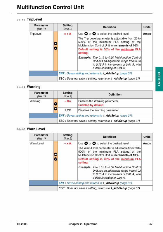
Multifunction Control Unit
EN
GL
ISH
2-5-4-6-3 TripLevel
2-5-4-6-4 Warning
2-5-4-6-5 Warn Level
Parameter(line 1)
Setting(line 2)
Definition Units
TripLevel = x A Use or to select the desired level.
The Trip Level parameter is adjustable from 20 to500% of the minimum FLA setting of theMultifunction Control Unit in increments of 10%. Default setting is 30% of the minimum FLAsetting.
Example: The 0.15 to 0.60 Multifunction ControlUnit has an adjustable range from 0.03to 0.75 A in increments of 0.01 A, witha default setting of 0.04 A.
Amps
ENT : Saves setting and returns to 4_AdvSetup (page 37).
ESC : Does not save a setting, returns to 4_AdvSetup (page 37).
Parameter(line 1)
Setting(line 2)
Definition
Warning = On Enables the Warning parameter.Enabled by default.
? Off Disables the Warning parameter.
ENT : Saves setting and returns to 4_AdvSetup (page 37).
ESC : Does not save a setting, returns to 4_AdvSetup (page 37).
Parameter(line 1)
Setting(line 2)
Definition Units
Warn Level = x A Use or to select the desired level.
The Warn Level parameter is adjustable from 20 to500% of the minimum FLA setting of theMultifunction Control Unit in increments of 10%. Default setting is 30% of the minimum FLAsetting.
Example: The 0.15 to 0.60 Multifunction ControlUnit has an adjustable range from 0.03to 0.75 A in increments of 0.01 A, witha default setting of 0.04 A.
Amps
ENT : Saves setting and returns to 4_AdvSetup (page 37).
ESC : Does not save a setting, returns to 4_AdvSetup (page 37).
05-2003 Chapter 2 - Operation 47

Multifunction Control UnitE
NG
LIS
H
2-5-4-7 47_PhaseImb (Phase Imbalance / Phase Loss Protection)
WARNINGIncorrect Phase Imbalance setting
• Phase Imbalance levels must be set to protect wiring and motor equipment,
• Function disabled if configured for 1 phase motor loads,
• Settings must conform to national and local safety regulations and codes.
Disabled or high Trip Level settings can result in death, serious injury, or equipmentdamage.
Function(line 1)
Parameter(line 2)
Definition
47_PhaseImb Trip
(see 2-5-4-7-1, p. 49)
Enables or disables the Phase Imbalance / PhaseLoss Protection Trip function.
A trip command is initiated if the MultifunctionControl Unit detects a continuous current in onephase that differs by more than a set percentagefrom the average current in all three phases for theset time period.
NOTE: Fault reset method for this function dependson the reset type selected(see 42_ResetMode, page 40)
TripTimeStrt
(see 2-5-4-7-2, p. 49)
Sets Phase Imbalance / Phase Loss ProtectionStart Mode Trip Time parameter.
The Start Mode Trip Time parameter is defined asthe amount of time (in seconds) during the RunStart Cycle that the set level of imbalance current isdetected before initiating a phase imbalance trip(see Chapter 3 - , Run Start Cycle, page 70).
TripTimeRun
(see 2-5-4-7-3, p. 50)
Sets Phase Imbalance / Phase Loss ProtectionRun Mode Trip Time parameter.
The Run Mode Trip Time parameter is defined asthe amount of time (in seconds) during the "Run"mode (settings) that the set TripLevel (page 50) ofimbalance current is detected before initiating aphase imbalance trip (see 2-2-3, "Run"mode (settings), page 21).
TripLevel
(see 2-5-4-7-4, p. 50)
Sets Phase Imbalance / Phase Loss ProtectionTrip Level parameter.
The Trip Level parameter is defined as the ratio ofimbalance current to the average current in all threephases that is detected for the set time period beforeinitiating a phase imbalance trip.
48 Chapter 2 - Operation 05-2003

Multifunction Control Unit
EN
GL
ISH
2-5-4-7-1 Trip
2-5-4-7-2 TripTimeStrt
(47_PhaseImb) Warning
(see 2-5-4-7-5, p. 50)
Enables or disables the Phase Imbalance / PhaseLoss Protection Warning function.
If the Multifunction Control Unit detects a phaseimbalance condition above the set Warn Level(page 50), a warning is actived.
The Warning deactivates itself when the imbalancecondition drops 5% below the set level.
Warn Level
(see 2-5-4-7-6, p. 50)
Sets the Phase Imbalance / Phase loss Warn Levelparameter.
NOTE: Press or to enable stepping through all the display parameters.
ENT : Sends to parameters settings.
ESC : Returns to 4_AdvSetup (page 37).
NOTE: If no key is depressed for a period of 5 seconds while in the "Run"mode (settings) (page 21), the scrolling display shall resume.
Parameter(line 1)
Setting(line 2)
Definition
Trip = On Enables the Phase Imbalance / Phase Loss ProtectionTrip parameter.Enabled by default.
? Off Disables the Phase Imbalance / Phase Loss ProtectionTrip parameter.
ENT : Saves setting and returns to 4_AdvSetup (page 37).
ESC : Does not save a setting, returns to 4_AdvSetup (page 37).
Parameter(line 1)
Setting(line 2)
Definition Units
TripTimeStrt = 0.7 Sec. Use or to select the desired time.
The Trip Time (RunStart) parameter is adjustablefrom 0.2 to 20 seconds in increments of 0.1seconds.Default setting is 0.7 second.
NOTE: For configuration of the Run Start Cycletime, see 410_LongStrt (page 39).
Sec.
ENT : Saves setting and returns to 4_AdvSetup (page 37).
ESC : Does not save a setting, returns to 4_AdvSetup (page 37).
Function(line 1)
Parameter(line 2)
Definition
05-2003 Chapter 2 - Operation 49

Multifunction Control UnitE
NG
LIS
H
2-5-4-7-3 TripTimeRun
2-5-4-7-4 TripLevel
2-5-4-7-5 Warning
2-5-4-7-6 Warn Level
Parameter(line 1)
Setting(line 2)
Definition Units
TripTimeRun = 5.0 Sec. Use or to select the desired time.
The Trip Time (Run Mode) parameter is adjustablefrom 0.2 to 20 seconds in increments of 0.1seconds. Default setting is 5 seconds.
NOTE: For information on the Run Start Cycletime, see 410_LongStrt (page 39).
Sec.
ENT : Saves setting and returns to 4_AdvSetup (page 37).
ESC : Does not save a setting, returns to 4_AdvSetup (page 37).
Parameter(line 1)
Setting(line 2)
Definition Units
TripLevel = 10% IMB Use or to select the desired level.
The Trip Level parameter is adjustable from 10 to30% Phase imbalance in increments of 1%.Default setting is 10% IMB.
% IMB
ENT : Saves setting and returns to 4_AdvSetup (page 37).
ESC : Does not save a setting, returns to 4_AdvSetup (page 37).
Parameter(line 1)
Setting(line 2)
Definition
Warning = On Enables the Warning parameter.Enabled by default.
? Off Disables the Warning parameter.
ENT : Saves setting and returns to 4_AdvSetup (page 37).
ESC : Does not save a setting, returns to 4_AdvSetup (page 37).
Parameter(line 1)
Setting(line 2)
Definition Units
Warn Level = 10% IMB Use or to select the desired level.
The Warn Level parameter is adjustable from 10 to30% phase imbalance in increments of 1%.Default setting is 10% IMB.
% IMB
ENT : Saves setting and returns to 4_AdvSetup (page 37).
ESC : Does not save a setting, returns to 4_AdvSetup (page 37).
50 Chapter 2 - Operation 05-2003

Multifunction Control Unit
EN
GL
ISH
2-5-4-8 48_Jam (Jam Protection)
2-5-4-8-1 Trip
Function(line 1)
Parameter(line 2)
Definition
48_Jam Trip
(see 2-5-4-8-1, p. 51)
Enables or disables the Jam Protection Trip function.
A trip command is initiated if the Multifunction ControlUnit detects a RMS current that exceeds a setTripLevel (page 52) for the set TripTime (page 52)period after the Run Start Cycle (page 70) has ended.
NOTE: Fault reset method for this function depends onthe reset type selected(see , 42_ResetMode, page 40)
TripTime
(see 2-5-4-8-2, p. 52)
Sets the Jam Protection Trip Time parameter.
The Trip Time parameter is defined as the amount oftime (in seconds) that a set TripLevel (page 52) of RMScurrent is detected before initiating a Jam Trip.
TripLevel
(see 2-5-4-8-3, p. 52)
Sets the Jam Protection Trip Level parameter.
The Trip Level parameter is defined as the ratio of RMScurrent to the FLA setting that is detected for a setTripTime (page 52) period before initiating a Jam Trip.
Warning
(see 2-5-4-8-4, p. 52)
Enables or disables the Jam Protection Warningfunction.
A warning will be activated if the Multifunction ControlUnit detects a Jam condition above a set Warn Level(page 52).
The Warning deactivates itself when the Jam conditiondrops 5% below the set level.
Warn Level
(see 2-5-4-8-5, p. 52)
Sets the Jam Protection Warn Level parameter.
NOTE: Press or to enable stepping through all the display parameters.
ENT : Sends to parameters settings.
ESC : Returns to 4_AdvSetup (page 37).
NOTE: If no key is depressed for a period of 5 seconds while in the "Run"mode (settings) (page 21), the scrolling display shall resume.
Parameter(line 1)
Setting(line 2)
Definition
Trip = Off Disables the Jam Protection Trip parameter.Disabled by default.
? On Enables the Jam Trip parameter.
ENT : Saves setting and returns to 4_AdvSetup (page 37).
ESC : Does not save a setting, returns to 4_AdvSetup (page 37).
05-2003 Chapter 2 - Operation 51

Multifunction Control UnitE
NG
LIS
H
2-5-4-8-2 TripTime
2-5-4-8-3 TripLevel
2-5-4-8-4 Warning
2-5-4-8-5 Warn Level
Parameter(line 1)
Setting(line 2)
Definition Units
TripTime = 5 Sec. Use or to select the desired time.
The Trip Time parameter is adjustable from 1 to 30seconds in increments of 1 second.Default setting is 5 seconds.
Sec.
ENT : Saves setting and returns to 4_AdvSetup (page 37).
ESC : Does not save a setting, returns to 4_AdvSetup (page 37).
Parameter(line 1)
Setting(line 2)
Definition Units
TripLevel = 200% FLA Use or to select the desired level.
The Trip Level parameter is adjustable from 100 to800% of the FLA setting in increments of 10%.Default setting is 200% FLA.
% FLA
ENT : Saves setting and returns to 4_AdvSetup (page 37).
ESC : Does not save a setting, returns to 4_AdvSetup (page 37).
Parameter(line 1)
Setting(line 2)
Definition
Warning = Off Disables the Warning parameter.Disabled by default.
? On Enables the Warning parameter.
ENT : Saves setting and returns to 4_AdvSetup (page 37).
ESC : Does not save a setting, returns to 4_AdvSetup (page 37).
Parameter(line 1)
Setting(line 2)
Definition Units
Warn Level = 200% FLA Use or to select the desired level.
The Warn Level parameter is adjustable from 100to 800% of the FLA setting in increments of 10%.Default setting is 200% FLA.
% FLA
ENT : Saves setting and returns to 4_AdvSetup (page 37).
ESC : Does not save a setting, returns to 4_AdvSetup (page 37).
52 Chapter 2 - Operation 05-2003
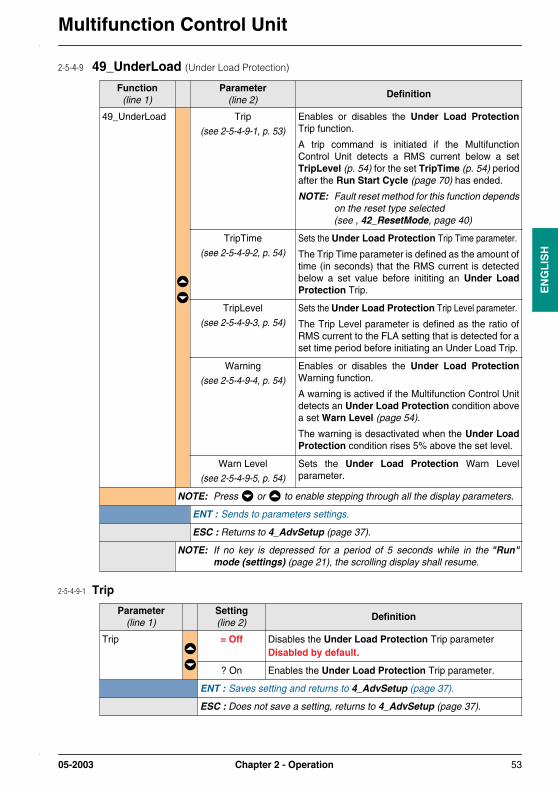
Multifunction Control Unit
EN
GL
ISH
2-5-4-9 49_UnderLoad (Under Load Protection)
2-5-4-9-1 Trip
Function(line 1)
Parameter(line 2)
Definition
49_UnderLoad Trip
(see 2-5-4-9-1, p. 53)
Enables or disables the Under Load ProtectionTrip function.
A trip command is initiated if the MultifunctionControl Unit detects a RMS current below a setTripLevel (p. 54) for the set TripTime (p. 54) periodafter the Run Start Cycle (page 70) has ended.
NOTE: Fault reset method for this function dependson the reset type selected(see , 42_ResetMode, page 40)
TripTime
(see 2-5-4-9-2, p. 54)
Sets the Under Load Protection Trip Time parameter.
The Trip Time parameter is defined as the amount oftime (in seconds) that the RMS current is detectedbelow a set value before inititing an Under LoadProtection Trip.
TripLevel
(see 2-5-4-9-3, p. 54)
Sets the Under Load Protection Trip Level parameter.
The Trip Level parameter is defined as the ratio ofRMS current to the FLA setting that is detected for aset time period before initiating an Under Load Trip.
Warning
(see 2-5-4-9-4, p. 54)
Enables or disables the Under Load ProtectionWarning function.
A warning is actived if the Multifunction Control Unitdetects an Under Load Protection condition abovea set Warn Level (page 54).
The warning is desactivated when the Under LoadProtection condition rises 5% above the set level.
Warn Level
(see 2-5-4-9-5, p. 54)
Sets the Under Load Protection Warn Levelparameter.
NOTE: Press or to enable stepping through all the display parameters.
ENT : Sends to parameters settings.
ESC : Returns to 4_AdvSetup (page 37).
NOTE: If no key is depressed for a period of 5 seconds while in the "Run"mode (settings) (page 21), the scrolling display shall resume.
Parameter(line 1)
Setting(line 2)
Definition
Trip = Off Disables the Under Load Protection Trip parameter Disabled by default.
? On Enables the Under Load Protection Trip parameter.
ENT : Saves setting and returns to 4_AdvSetup (page 37).
ESC : Does not save a setting, returns to 4_AdvSetup (page 37).
05-2003 Chapter 2 - Operation 53

Multifunction Control UnitE
NG
LIS
H
2-5-4-9-2 TripTime
2-5-4-9-3 TripLevel
2-5-4-9-4 Warning
2-5-4-9-5 Warn Level
Parameter(line 1)
Setting(line 2)
Definition Units
TripTime = 10 Sec. Use or to select the desired time.
The Trip Time parameter is adjustable from 1 to200 seconds in increments of 1 second.Default setting is 10 seconds.
Sec.
ENT : Saves setting and returns to 4_AdvSetup (page 37).
ESC : Does not save a setting, returns to 4_AdvSetup (page 37).
Parameter(line 1)
Setting(line 2)
Definition Units
TripLevel = 50% FLA Use or to select the desired level.
The Trip Level parameter is adjustable from 30 to100% of the FLA setting in increments of 1%.Default setting is 50% FLA.
% FLA
ENT : Saves setting and returns to 4_AdvSetup (page 37).
ESC : Does not save a setting, returns to 4_AdvSetup (page 37).
Parameter(line 1)
Setting(line 2)
Definition
Warning = Off Disables the Warning parameter.Disabled by default.
? On Enables the Warning parameter.
ENT : Saves setting and returns to 4_AdvSetup (page 37).
ESC : Does not save a setting, returns to 4_AdvSetup (page 37).
Parameter(line 1)
Setting(line 2)
Definition Units
Warn Level = 50% FLA Use or to select the desired level.
The Warn Level parameter is adjustable from 30 to100% of the FLA setting in increments of 1%.Default setting is 50% FLA.
% FLA
ENT : Saves setting and returns to 4_AdvSetup (page 37).
ESC : Does not save a setting, returns to 4_AdvSetup (page 37).
54 Chapter 2 - Operation 05-2003
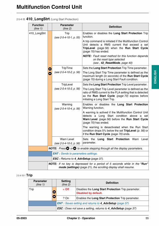
Multifunction Control Unit
EN
GL
ISH
2-5-4-10 410_LongStrt (Long Start Protection)
2-5-4-10-1 Trip
Function(line 1)
Parameter(line 2)
Definition
410_LongStrt Trip
(see 2-5-4-10-1, p. 55)
Enables or disables the Long Start Protection Tripfunction.
A trip command is initiated if the Multifunction ControlUnit detects a RMS current that exceed a setTripLevel (page 56) when the Run Start Cycle(page 70) has ended.
NOTE: Fault reset method for this function dependson the reset type selected(see , 42_ResetMode, page 40)
TripTime
(see 2-5-4-10-2, p. 56)
Sets the Long Start Protection Trip Time parameter.
The Long Start Trip Time parameter is defined as themaximum length (in seconds) of the Run Start Cycle(page 70) during a Long Start Fault condition.
TripLevel
(see 2-5-4-10-3, p. 56)
Sets the Long Start Protection Trip Level parameter.
The Long Start Trip Level parameter is defined as theratio of RMS current to the FLA setting that is detectedas the Run Start Cycle (page 70) expires beforeinitiating a Long Start Trip.
Warning
(see 2-5-4-10-4, p. 56)
Enables or disables the Long Start ProtectionWarning function.
A warning is actived if the Multifunction Control Unitdetects a Long Start condition above a setWarn Level (page 56) before the Run Start Cycle(page 70) has ended.
The warning is desactivated when the Run Startcondition drops 5% below the set TripLevel (p. 56) orif the Run Start Cycle (page 70) ends.
Warn Level
(see 2-5-4-10-5, p. 56)
Sets the Long Start Protection Warn Levelparameter.
NOTE: Press or to enable stepping through all the display parameters.
ENT : Sends to parameters settings.
ESC : Returns to 4_AdvSetup (page 37).
NOTE: If no key is depressed for a period of 5 seconds while in the "Run"mode (settings) (page 21), the scrolling display shall resume.
Parameter(line 1)
Setting(line 2)
Definition
Trip = Off Disables the Long Start Protection Trip parameter.Disabled by default.
? On Enables the Long Start Protection Trip parameter.
ENT : Saves setting and returns to 4_AdvSetup (page 37).
ESC : Does not save a setting, returns to 4_AdvSetup (page 37)
05-2003 Chapter 2 - Operation 55

Multifunction Control UnitE
NG
LIS
H
2-5-4-10-2 TripTime
2-5-4-10-3 TripLevel
2-5-4-10-4 Warning
2-5-4-10-5 Warn Level
Parameter(line 1)
Setting(line 2)
Definition Units
TripTime = 10 Sec. Use or to select the desired time.
The Trip Time parameter is adjustable from 1 to200 seconds in increments of 1 second.Default setting is 10 seconds.
Sec.
ENT : Saves setting and returns to 4_AdvSetup (page 37).
ESC : Does not save a setting, returns to 4_AdvSetup (page 37).
Parameter(line 1)
Setting(line 2)
Definition Units
TripLevel = 100% FLA Use or to select the desired level.
The Trip Level parameter is adjustable from 100 to800% of the FLA setting in increments of 10%.Default setting is 100% FLA.
% FLA
ENT : Saves setting and returns to 4_AdvSetup (page 37).
ESC : Does not save a setting, returns to 4_AdvSetup (page 37).
Parameter(line 1)
Setting(line 2)
Definition
Warning = Off Disables the Warning parameter.Disabled by default.
? On Enables the Warning parameter.
ENT : Saves setting and returns to 4_AdvSetup (page 37).
ESC : Does not save a setting, returns to 4_AdvSetup (page 37).
Parameter(line 1)
Setting(line 2)
Definition Units
Warn Level = 100% FLA Use or to select the desired level.
The Warn Level parameter is adjustable from 100to 800% of the FLA setting in increments of 10%.Default setting is 100% FLA.
% FLA
ENT : Saves setting and returns to 4_AdvSetup (page 37).
ESC : Does not save a setting, returns to 4_AdvSetup (page 37).
56 Chapter 2 - Operation 05-2003

Multifunction Control Unit
EN
GL
ISH
2-5-5 5_CommSetup• The 5_CommSetup submenu allows access to the controls of the RS 485 serial port (compatible
with Modbus® protocol) on the front face of the Multifunction Control Unit.
• The RS 485 asynchronous interface supports the Modbus® RTU slave protocol.
• Remote display or configuration devices must be Modbus® RTU masters which initiate communications by reading and writing 16 bits register data in the Multifunction Control Unit. See Appendix C - Register data format (page 77).
• See 1-3-6-4 RS 485 Serial port RJ-45 connector (page 17).
• For detailed information, on the Modbus® protocol, see <www.modbus.org>.
WARNINGImproper communication port usage
• Communication ports should be used for non-critical data transfers only,
• Monitoring of contactor status and current levels are delayed by transmission time and shouldnot be used for critical control decisions,
• Functions such as ShuntTrip, and Pause should not be used for emergency or critical controlapplications.
Improper use of Communication Ports can result in death, serious injury, or equipmentdamage.
Submenu(line 1)
Function(line 2)
Definition
5_CommSetup 51_Drop
(see 2-5-5-1, p. 58)
Sets the RS 485 serial port Drop parameter.
The Drop parameter is defined as the configurableModbus® slave number for the external RS 485 serialport.
52_Baud
(see 2-5-5-2, p. 59)
Sets the RS 485 serial port Baud rate parameter.
The Baud rate parameter defines the speed at whichthe Multifunction Control Unit can communicate withan external Modbus® device.
53_Parity
(see 2-5-5-3, p. 59)
Sets the asynchronous protocol parity for the externalRS 485 serial port.
05-2003 Chapter 2 - Operation 57

Multifunction Control UnitE
NG
LIS
H
2-5-5-1 51_Drop (Modbus® Slave Number)
(5_CommSetup) 54_Control
(see 2-5-5-4, p. 59)
Enables or disables write access by remoteconfiguration devices through the external RS 485serial port.If this function is disabled, changes to the protectionsettings via the external RS 485 serial port can not bemade.Write commands to the following registers are alwayspossible and not affected.- Remote keypad (register 1100)- Multifunction Control Units state control (register 704)- Multifunction Control Units extended state control
(register 705)- Option module configuration (registers 680-690)- Private registers above 20000
NOTE: Write commands are disabled while theMultifunction Control Unit is in the "Run"mode (monitoring) (page 22) except forwrites to the 31_FLASet (page 35) Setting(register 653) and the list of " - alwaysenabled - " registers above.Changes to configuration registers 600through 626 are disabled while keypadchanges are in process.
55_CommLoss
(see 2-5-5-5, p. 60)
Enables or disables the external RS 485 serial portwatchdog.
A CommLoss fault is defined as any inactive periodlonger than 5 seconds.
A start delay of 10 seconds follows each time coilcontrol power is applied to the A1, A2 terminals.
NOTE: Press or to enable stepping through all the display functions.
ENT : Sends to functions settings.
ESC : Returns to Main Menu (page 28).
NOTE: If no key is depressed for a period of 5 seconds while in the "Run"mode (settings) (page 21), the scrolling display shall resume.
Function(line 1)
Setting(line 2)
Definition
51_Drop = 1 Use or to select the desired Modbus® SlaveNumber can be selected.
The Modbus® Slave Number parameter is selectable from 1 to 247. Default setting is 1.
ENT : Saves setting and returns to 5_CommSetup (page 57).
ESC : Does not save a setting, returns to 5_CommSetup (page 57).
Submenu(line 1)
Function(line 2)
Definition
58 Chapter 2 - Operation 05-2003

Multifunction Control Unit
EN
GL
ISH
2-5-5-2 52_Baud (Modbus® Baud Rate)
2-5-5-3 53_Parity (Asynchronous Protocol Parity)
2-5-5-4 54_Control (Write Control)
Function(line 1)
Setting(line 2)
Definition Units
52_Baud = 19200 bps Sets the Modbus® Baud Rate parameter to19200 bps.Enabled by default.
bps
? 9600 Sets the Modbus® Baud Rate parameter to9600 bps.
? 4800 Sets the Modbus® Baud Rate parameter to4800 bps.
? 1200 Sets the Modbus® Baud Rate parameter to1200 bps.
ENT : Saves setting and returns to 5_CommSetup (page 57).
ESC : Does not save a setting, returns to 5_CommSetup (page 57).
Function(line 1)
Setting(line 2)
Definition
53_Parity = None Sets the Asynchronous Protocol Parity parameter toNone.
(1 start bit, 8 data bits, and 1 stop bit).Enabled by default.
? Even Sets the Asynchronous Protocol Parity parameter toEven.
(1 start bit, 8 data bits, even parity, and 1 stop bit).
ENT : Saves setting and returns to 5_CommSetup (page 57).
ESC : Does not save a setting, returns to 5_CommSetup (page 57).
Function(line 1)
Setting(line 2)
Definition
54_Control = On Enables the Write Control parameter allowing writecommands.Enabled by default.
? Off Disables the Write Control parameter.
ENT : Saves setting and returns to 5_CommSetup (page 57).
ESC : Does not save a setting, returns to 5_CommSetup (page 57).
05-2003 Chapter 2 - Operation 59
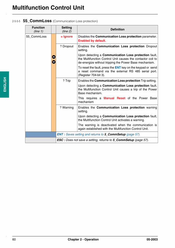
Multifunction Control UnitE
NG
LIS
H
2-5-5-5 55_CommLoss (Communication Loss protection)
Function(line 1)
Setting(line 2)
Definition
55_CommLoss = Ignore Disables the Communication Loss protection parameter.Enabled by default.
? Dropout Enables the Communication Loss protection Dropoutsetting.
Upon detecting a Communication Loss protection fault,the Multifunction Control Unit causes the contactor coil tode-energize without tripping the Power Base mechanism.
To reset the fault, press the ENT key on the keypad or senda reset command via the external RS 485 serial port.(Register 704-bit 3).
? Trip Enables the Communication Loss protection Trip setting.
Upon detecting a Communication Loss protection fault,the Multifunction Control Unit causes a trip of the PowerBase mechanism.
This requires a Manual Reset of the Power Basemechanism
? Warning Enables the Communication Loss protection warningsetting.
Upon detecting a Communication Loss protection fault,the Multifunction Control Unit activates a warning.
The warning is deactivated when the communication isagain established with the Multifunction Control Unit.
ENT : Saves setting and returns to 5_CommSetup (page 57).
ESC : Does not save a setting, returns to 5_CommSetup (page 57).
60 Chapter 2 - Operation 05-2003
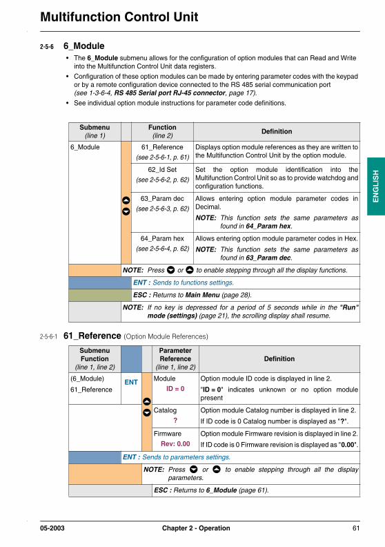
Multifunction Control Unit
EN
GL
ISH
2-5-6 6_Module• The 6_Module submenu allows for the configuration of option modules that can Read and Write
into the Multifunction Control Unit data registers.
• Configuration of these option modules can be made by entering parameter codes with the keypad or by a remote configuration device connected to the RS 485 serial communication port (see 1-3-6-4, RS 485 Serial port RJ-45 connector, page 17).
• See individual option module instructions for parameter code definitions.
2-5-6-1 61_Reference (Option Module References)
Submenu(line 1)
Function(line 2)
Definition
6_Module 61_Reference
(see 2-5-6-1, p. 61)
Displays option module references as they are written tothe Multifunction Control Unit by the option module.
62_Id Set
(see 2-5-6-2, p. 62)
Set the option module identification into theMultifunction Control Unit so as to provide watchdog andconfiguration functions.
63_Param dec
(see 2-5-6-3, p. 62)
Allows entering option module parameter codes inDecimal.
NOTE: This function sets the same parameters asfound in 64_Param hex.
64_Param hex
(see 2-5-6-4, p. 62)
Allows entering option module parameter codes in Hex.
NOTE: This function sets the same parameters asfound in 63_Param dec.
NOTE: Press or to enable stepping through all the display functions.
ENT : Sends to functions settings.
ESC : Returns to Main Menu (page 28).
NOTE: If no key is depressed for a period of 5 seconds while in the "Run"mode (settings) (page 21), the scrolling display shall resume.
SubmenuFunction
(line 1, line 2)
ParameterReference
(line 1, line 2)Definition
(6_Module)
61_ReferenceENT Module
ID = 0Option module ID code is displayed in line 2.
"ID = 0" indicates unknown or no option modulepresent
Catalog
?Option module Catalog number is displayed in line 2.
If ID code is 0 Catalog number is displayed as "?".
Firmware
Rev: 0.00Option module Firmware revision is displayed in line 2.
If ID code is 0 Firmware revision is displayed as "0.00".
ENT : Sends to parameters settings.
NOTE: Press or to enable stepping through all the displayparameters.
ESC : Returns to 6_Module (page 61).
05-2003 Chapter 2 - Operation 61

Multifunction Control UnitE
NG
LIS
H
2-5-6-2 62_Id Set (Option Module Identification number)
2-5-6-3 63_Param dec (Option Module Parameter Dec setting)
2-5-6-4 64_Param hex (Option Module Parameter Hex setting)
Function(line 1)
Setting(line 2)
Definition
62_Id Set = 0 Use or to select the desired option module IDnumber.
The ID set parameter is settable from 0 to 149. Default setting is 0
ENT : Saves setting and returns to 6_Module (page 61).
ESC : Does not save a setting, returns to 6_Module (page 61).
SubmenuFunction
(line 1, line 2)
ParameterReference
(line 1, line 2)Definition
(6_Module)
63_Param decENT Parameter 1-10
= 00000(see § 2-5-6-5)
Line 1 shows the parameter number (1 through 10)
Line 2 shows the parameter setting in decimal.The parameters are settable from 00000 to 65535. Default setting, for all 10 parameters, is 00000
ENT : Sends to parameters settings.
NOTE: Press or to enable stepping through all the parametersnumbers.
ESC : Returns to 6_Module (page 61).
SubmenuFunction
(line 1, line 2)
ParameterReference
(line 1, line 2)Definition
(6_Module)
64_Param hexENT Parameter 1-10
= 0000(see § 2-5-6-5)
Line 1 shows the parameter number (1 through 10)
Line 2 shows the parameter setting in Hex.The parameters are settable from 0000 to FFFF. Default setting, for all 10 parameters, is 0000
ENT : Sends to parameters settings.
NOTE: Press or to enable stepping through all the parametersnumbers.
ESC : Returns to 6_Module (page 61).
62 Chapter 2 - Operation 05-2003
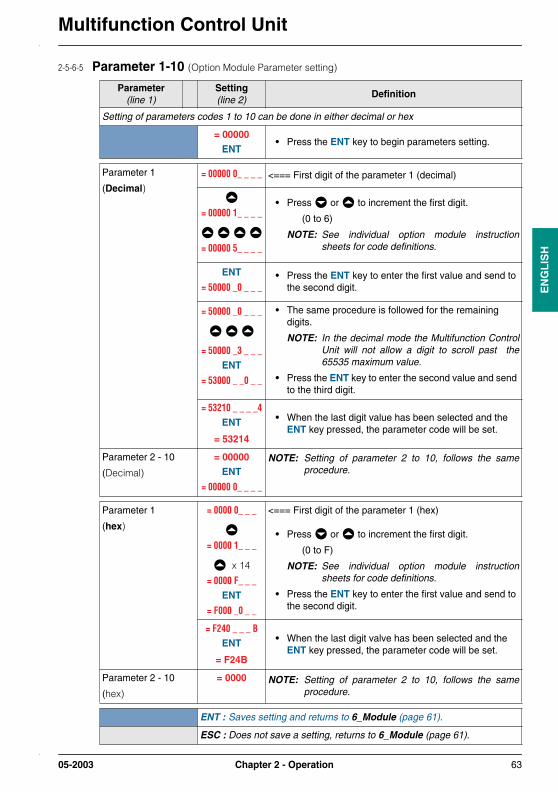
Multifunction Control Unit
EN
GL
ISH
2-5-6-5 Parameter 1-10 (Option Module Parameter setting)
Parameter(line 1)
Setting(line 2)
Definition
Setting of parameters codes 1 to 10 can be done in either decimal or hex
= 00000ENT
• Press the ENT key to begin parameters setting.
Parameter 1
(Decimal)= 00000 0_ _ _ _ <=== First digit of the parameter 1 (decimal)
= 00000 1_ _ _ _
= 00000 5_ _ _ _
• Press or to increment the first digit.
(0 to 6)
NOTE: See individual option module instructionsheets for code definitions.
ENT
= 50000 _0 _ _ _• Press the ENT key to enter the first value and send to
the second digit.
= 50000 _0 _ _ _
= 50000 _3 _ _ _ENT
= 53000 _ _0 _ _
• The same procedure is followed for the remaining digits.
NOTE: In the decimal mode the Multifunction ControlUnit will not allow a digit to scroll past the65535 maximum value.
• Press the ENT key to enter the second value and send to the third digit.
= 53210 _ _ _ _4ENT
= 53214
• When the last digit value has been selected and the ENT key pressed, the parameter code will be set.
Parameter 2 - 10
(Decimal)
= 00000ENT
= 00000 0_ _ _ _
NOTE: Setting of parameter 2 to 10, follows the sameprocedure.
Parameter 1
(hex)
= 0000 0_ _ _
= 0000 1_ _ _
x 14
= 0000 F_ _ _ ENT
= F000 _0 _ _
<=== First digit of the parameter 1 (hex)
• Press or to increment the first digit.
(0 to F)
NOTE: See individual option module instructionsheets for code definitions.
• Press the ENT key to enter the first value and send to the second digit.
= F240 _ _ _ BENT
= F24B
• When the last digit valve has been selected and the ENT key pressed, the parameter code will be set.
Parameter 2 - 10
(hex)
= 0000 NOTE: Setting of parameter 2 to 10, follows the sameprocedure.
ENT : Saves setting and returns to 6_Module (page 61).
ESC : Does not save a setting, returns to 6_Module (page 61).
05-2003 Chapter 2 - Operation 63

Multifunction Control UnitE
NG
LIS
H
2-5-7 7_Statistics• The 7_Statistics submenu allows access to the Fault history stored in the Multifunction Control
Unit memory.
• The Multifunction Control Unit stores information on the last 5 Faults as well as Fault and Run history totals.
NOTE: Internal Fault Trips are not displayed in last 5 faults.
• Enabling the 83_Rst Stats (page 67) function clears all stored statistics data.
• The Fault history can be accessed during the "Run" mode (settings) (page 21) or "Off" mode (first power-up) (page 19) or "Off" mode (subsequent power-ups) (page 20).
2-5-7-1 71_Trip0 (Historical Information (Last fault))
Submenu(line 1)
Function(line 2)
Definition
7_Statistics 71_Trip0
(see 2-5-7-1, p. 64)
Contains stored Historical Information (Last fault)detected.
72_Trip1
(see 2-5-7-2, p. 65)
Contains stored Historical Information (Second tolast fault) detected.
73_Trip2
(see 2-5-7-3, p. 65)
Contains stored Historical Information (Third to lastfault) detected.
74_Trip3
(see 2-5-7-4, p. 65)
Contains stored Historical Information (Fourth to lastfault) detected.
75_Trip4
(see 2-5-7-5, p. 66)
Contains stored Historical Information (Fifth to lastfault) detected.
76_Totals
(see 2-5-7-6, p. 66)
Contains Historical Count Totals for Start, Run andFault Events as detected by the Multifunction ControlUnit.
NOTE: Press the ENT key to view the Totals item infirst line and the actual count in the second line.
NOTE: Press or to enable stepping through all functions.
ENT : Sends to function.
ESC : Returns to Main Menu (page 28).
NOTE: If no key is depressed for a period of 5 seconds while in the "Run"mode (settings) (page 21), the scrolling display shall resume.
Function(line 1)
Value(line 2)
Definition Units
71_Trip0 Type=xxxxxxx The Type=xxxxxxx Statistics Item shows the typeof fault detected.See Appendix B - Display Words (page 75) forfault types.
-
FLA= xxx A The FLA = xxx A Statistics Item shows setting ofthe 31_FLASet (page 34) function in Amps(4).
Amps
IAV= xxx A The IAV = xxx A Statistics Item shows the averagecurrent in amps as measure by the MultifunctionControl Unit(4).
Amps
64 Chapter 2 - Operation 05-2003

Multifunction Control Unit
EN
GL
ISH
2-5-7-2 72_Trip1 (Historical Information (Second to last fault))
2-5-7-3 73_Trip2 (Historical Information (Third to last fault))
2-5-7-4 74_Trip3 (Historical Information (Fourth to last fault))
(71_Trip0) IL1= xxx A The IL1 = xxx A Statistics Item shows the L1current in amps as measure by the MultifunctionControl Unit(4).
Amps
IL2= xxx A The IL2 = xxx A Statistics Item shows the L2current in amps as measure by the MultifunctionControl Unit(4).
Amps
IL3= xxx A The IL3 = xxx A Statistics Item shows the L3current in amps as measure by the MultifunctionControl Unit(4).
Amps
IGR= xxx A The IGR = xxx A Statistics Item shows the groundfault current in amps as measure by theMultifunction Control Unit(4).
Amps
Therm= xxx% The Therm = xxx% Statistics Item shows thethermal capacity in % of thermal capacity used.
% FLA
NOTE: Press or to enable stepping through all values.
ESC : Returns to 7_Statistics (page 64).
(5) when the fault is detected
Function(line 1)
Value(line 2)
Definition
72_Trip1 The items found under this function are identical to those found under71_Trip0 (page 64).
NOTE: Press or to enable stepping through all functions.
ESC : Returns to 7_Statistics (page 64).
Function(line 1)
Value(line 2)
Definition
73_Trip2 The items found under this function are identical to those found under71_Trip0 (page 64).
NOTE: Press or to enable stepping through all functions.
ESC : Returns to 7_Statistics (page 64).
Function(line 1)
Value(line 2)
Definition
74_Trip3 The items found under this function are identical to those found under71_Trip0 (page 64).
NOTE: Press or to enable stepping through all functions.
ESC : Returns to 7_Statistics (page 64).
Function(line 1)
Value(line 2)
Definition Units
05-2003 Chapter 2 - Operation 65
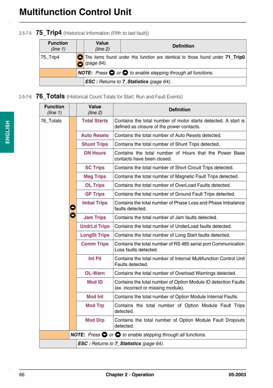
Multifunction Control UnitE
NG
LIS
H
2-5-7-5 75_Trip4 (Historical Information (Fifth to last fault))
2-5-7-6 76_Totals (Historical Count Totals for Start, Run and Fault Events)
Function(line 1)
Value(line 2)
Definition
75_Trip4 The items found under this function are identical to those found under 71_Trip0(page 64).
NOTE: Press or to enable stepping through all functions.
ESC : Returns to 7_Statistics (page 64).
Function(line 1)
Value(line 2)
Definition
76_Totals Total Starts Contains the total number of motor starts detected. A start isdefined as closure of the power contacts.
Auto Resets Contains the total number of Auto Resets detected.
Shunt Trips Contains the total number of Shunt Trips detected.
ON Hours Contains the total number of Hours that the Power Basecontacts have been closed.
SC Trips Contains the total number of Short Circuit Trips detected.
Mag Trips Contains the total number of Magnetic Fault Trips detected.
OL Trips Contains the total number of OverLoad Faults detected.
GF Trips Contains the total number of Ground Fault Trips detected.
Imbal Trips Contains the total number of Phase Loss and Phase Imbalancefaults detected.
Jam Trips Contains the total number of Jam faults detected.
UndrLd Trips Contains the total number of UnderLoad faults detected.
LongSt Trips Contains the total number of Long Start faults detected.
Comm Trips Contains the total number of RS 485 serial port CommunicationLoss faults detected.
Int Flt Contains the total number of Internal Multifunction Control UnitFaults detected.
OL-Warn Contains the total number of Overload Warnings detected.
Mod ID Contains the total number of Option Module ID detection Faults(ex. incorrect or missing module).
Mod Int Contains the total number of Option Module Internal Faults.
Mod Trp Contains the total number of Option Module Fault Tripsdetected.
Mod Drp Contains the total number of Option Module Fault Dropoutsdetected.
NOTE: Press or to enable stepping through all functions.
ESC : Returns to 7_Statistics (page 64).
66 Chapter 2 - Operation 05-2003
Multifunction Control Unit
EN
GL
ISH
2-5-8 8_Password• The 8_Password submenu allows Password protection that prevents unauthorized access to the
Multifunction Control Unit configuration.
• The factory default password of 0000 disables the password feature.
• The range for the password is from 0001 to 9999.
• This submenu also contains the functions that resets the configurable functions and statisticsinformation back to factory settings.
Submenu(line 1)
Function(line 2)
Definition
8_Password 81_Unlock
(see 2-5-8-1, p. 68)
Disables the password protection function.
If the password function 82_Lock (page 67) is enabled,it must be disabled before changes to the MultifunctionControl Unit settings can be made.
NOTE: The Multifunction Control Unit display prompts you to enter the password if you try to change a setting with the password enabled.
Once unlocked, the password feature is onlytemporarily disabled until one of the following eventsoccurs:
• The ESC key is pressed while at the Main Menu (page 28), the Keypad is inactive for more than 15 seconds, coil control power is applied, or both coil control and auxiliary control power are removed.
• Changes via the external Modbus® RS 485 serial ports are inhibited while changing functions from the Keypad.
82_Lock
(see 2-5-8-2, p. 69)
Enables the password protection function in theMultifunction Control Unit.
The default password of 0000 completely disables thepassword feature.
NOTE: The password value can be changed via theexternal Modbus® RS 485 and internal OptionModule serial ports, only if the currentpassword is zero (disabled).
83_Rst Stats
(see 2-5-8-3, p. 69)
Resets all Statistics and Fault history values to 0.
(see 7_Statistics, page 64).
NOTE: Statistics values cannot be recovered afterRstStats function is enabled. External programming devices can be used tosave or download the Multifunction Control Unitstatistics values.
05-2003 Chapter 2 - Operation 67
Multifunction Control UnitE
NG
LIS
H
2-5-8-1 81_Unlock (Disable Password Protection)
(8_Password) 84_RstToDfts
(see 2-5-8-4, p. 69)
Resets all configurable functions back to factory defaultsettings.
Enabling this function sends user back to theConfig Menu (page 25).
This function does not reset the Statistics values(see 83_Rst Stats, page 67).
NOTE: Function settings can not be recovered oncethe 84_RstToDfts (page 69) function has beenenabled. External programming devices can be used tosave or download the Multifunction Control Unitfunction settings.
NOTE: Press or to enable stepping through all the display functions.
ENT : Sends to functions settings.
ESC : Returns to Main Menu (page 28).
NOTE: If no key is depressed for a period of 5 seconds while in the "Run"mode (settings) (page 21), the scrolling display shall resume.
Function(line 1)
Setting(line 2)
Definition
81_Unlock Passwd?
(0001 - 9999)
The Disable Password Protection function initiates theunlock sequence.
The Multifunction Control Unit displays Passwd?.
• Use or to increment the first digit from 0 to 9.
• Press the ENT key to enter the first value and move to the second digit.
• The same procedure is followed for the second, third and fourth digits.
• Once the fourth and last digit has been selected and the ENT key is pressed, a setting can be modified.
NOTE: The Disable Password Protection function onlydisables the password feature temporarily. The password must be set at 0000 to completelydisable the password.
ENT : Saves setting and returns to 8_Password (page 67).
ESC : Does not save a setting, returns to 8_Password (page 67).
Submenu(line 1)
Function(line 2)
Definition
68 Chapter 2 - Operation 05-2003

Multifunction Control Unit
EN
GL
ISH
2-5-8-2 82_Lock (Enable Password Protection)
2-5-8-3 83_Rst Stats (Resets the Statistics)
2-5-8-4 84_RstToDfts (Resets all Configurable Functions to factory default settings)
Function(line 1)
Setting(line 2)
Definition
82_Lock NewPSW?
(0001 - 9999)
The Enable Password Protection function initiates thelock sequence.
The Multifunction Control Unit displays NewPSW?.
• Use or to increment the first digit from 0 to 9.
• Press the ENT key to enter the first value and move to the second digit.
• The same procedure is followed for the second, third and fourth digits.
• Once the fourth and last digit has been selected and the ENT key is pressed: ==> the Multifunction Control Unit displays shows Confirm••••.
• You must then reenter the four values as before.
ENT : Upon finishing the reentry of the password value, the display quicklyshows Done and then returns to 8_Password (page 67).
ESC : Does not save a setting, returns to 8_Password (page 67).
Function(line 1)
Setting(line 2)
Definition
83_Rst Stats = No Disables the Resets the Statistics function.Disabled by default.
? Yes Enables the Resets the Statistics function clearing allstatistics.
ENT : Saves setting and returns to 8_Password (page 67).
ESC : Does not save a setting, returns to 8_Password (page 67).
Function(line 1)
Setting(line 2)
Definition
84_RstToDfts = No Disables the Resets all Configurable Functions tofactory default settings function.Disabled by default.
? Yes Enables the Resets all Configurable Functions tofactory default settings function clearing all settings.
ENT : Saves setting and returns to 8_Password (page 67).
ESC : Does not save a setting, returns to 8_Password (page 67).
05-2003 Chapter 2 - Operation 69

Multifunction Control UnitE
NG
LIS
H
Chapter 3 - Run Start Cycle• The Run Start Cycle is the period of time allowed for a motor to reach its normal full load current
level after starting.
• This cycle time, which is adjustable in the 410_LongStrt (page 39) function, is used to set the startdelays for the 48_Jam, 49_UnderLoad and 47_PhaseImb protection functions.
NOTE: The 410_LongStrt (page 39) function will not override the thermal overload protection. If the Multifunction Control Unit reaches the limit of its thermal capacity during the RunStart Cycle, the device trips on a thermal overload fault.
• The length of the Run Start Cycle is determined by one of five methods as described below:
- - - - - - - - - - - - - - - - - - - - - - - - - - - - - - - - - - - - - - - - - - - - - - - - - - - - - - - - - - - - - - - - - - - - - - - - - - - - - - - - - - - - - - - - - - - - - - - - - - - - - - - - - - - - - - - - - - - - - - - - - - - - - - - - - - - - -
1) The time period from when coil control power is applied to A1, A2 terminals on the Power Base,until the motor load current drops below the 150% FLA current threshold:- with the 410_LongStrt (page 39) function Trip or Warning parameter " - Disabled - ".- for currents that exceed 150% FLA current threshold.
- - - - - - - - - - - - - - - - - - - - - - - - - - - - - - - - - - - - - - - - - - - - - - - - - - - - - - - - - - - - - - - - - - - - - - - - - - - - - - - - - - - - - - - - - - - - - - - - - - - - - - - - - - - - - - - - - - - - - - - - - - - - - - - - - - - - -
2) A time period of 10 seconds that starts when coil control power is applied to A1, A2 terminalson the Power Base:- with the 410_LongStrt (page 39) function Trip or Warning parameter " - Disabled - ".- for currents that continuously exceed 150% FLA current threshold.- for currents that never exceed 150% FLA current threshold.
RunStart CurrentThreshold150% FLA
Current
TimeRunStart Time begins whenCoil control power is applied to A1, A2 terminals
RunStart Time
Max. RunStart Time10 sec.
Max. RunStart Time10 sec.
RunStart CurrentThreshold150% FLA
Current
TimeRunStart Time begins whenCoil control power is applied to A1, A2 terminals
RunStart Time
70 Chapter 3 - Run Start Cycle 05-2003

Multifunction Control Unit
EN
GL
ISH
3) The time period from when coil control power is applied to A1, A2 terminals on the Power Base,until the motor load current drops below an adjustable TripLevel current threshold:- with the 410_LongStrt (page 39) function Trip or Warning parameter " - Enabled - ".- for currents that exceed the adjustable TripLevel current threshold.
- - - - - - - - - - - - - - - - - - - - - - - - - - - - - - - - - - - - - - - - - - - - - - - - - - - - - - - - - - - - - - - - - - - - - - - - - - - - - - - - - - - - - - - - - - - - - - - - - - - - - - - - - - - - - - - - - - - - - - - - - - - - - - - - - - - - -
4) An adjustable TripTime period that starts when coil control power is applied to A1, A2 terminalson the Power Base:- with the 410_LongStrt (page 39) function Trip or Warning parameter " - Enabled - ".- for currents that continuously exceed the adjustable TripLevel current threshold.
NOTE: Under this condition, the device will initiate a Trip or Warning at the end of this RunStart Cycle.
- - - - - - - - - - - - - - - - - - - - - - - - - - - - - - - - - - - - - - - - - - - - - - - - - - - - - - - - - - - - - - - - - - - - - - - - - - - - - - - - - - - - - - - - - - - - - - - - - - - - - - - - - - - - - - - - - - - - - - - - - - - - - - - - - - - - -
5) An adjustable TripTime period that starts when coil control power is applied to A1, A2 terminalson the Power Base:- with the 410_LongStrt (page 39) function Trip or Warning parameter " - Enabled - ".- for currents that never exceed the adjustable TripLevel current threshold.
NOTE: Under this condition, the device will not initiate a Trip or Warning at the end of thisRun Start Cycle.
Adjustable TripTime1 to 200 sec. (10 sec. by default)
Adjustable TripLevelCurrent Threshold100% to 800% FLA(150% by default)
Current
TimeRunStart Time begins whenCoil control power is applied to A1, A2 terminals
RunStart Time
Adjustable TripLevelCurrent Threshold100% to 800% FLA(150% by default)
Current
Time
RunStart Time
Adjustable TripTime1 to 200 sec. (10 sec. by default)
RunStart Time begins whenCoil control power is applied to A1, A2 terminals
RunStart Time
Adjustable TripLevelCurrent Threshold100% to 800% FLA(150% by default)
Current
TimeAdjustable TripTime1 to 200 sec. (10 sec. by default)
RunStart Time begins whenCoil control power is applied to A1, A2 terminals
05-2003 Chapter 3 - Run Start Cycle 71
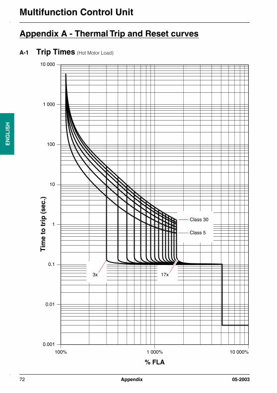
Multifunction Control UnitE
NG
LIS
H
Appendix A - Thermal Trip and Reset curves
A-1 Trip Times (Hot Motor Load)
10 000
1 000
100
10
1
0.1
0.01
0.001
100% 1 000%
Class 30
% FLA
Tim
e to
tri
p (
sec.
)
10 000%
Class 5
3x 17x
72 Appendix 05-2003

Multifunction Control Unit
EN
GL
ISH
A-2 Trip Times (Cold Motor Load)
10 000
1 000
100
10
1
0.1
0.01
0.001
100% 1 000%
% FLA
Tim
e to
tri
p (
sec.
)
10 000%
Class 30
Class 5
3x 17x
05-2003 Appendix 73

Multifunction Control UnitE
NG
LIS
H
A-3 Reset Times (With Aux Fan Cooled function "disabled")
A-4 Reset Times (With Aux Fan Cooled function "enabled")
0
10
20
30
40
50
60
70
80
90
100
0 1000 2000 3000 4000 5000 6000 7000
Time to reset
Res
et L
evel
(%
of t
herm
al o
verlo
ad tr
ip le
vel)
Reset Timing - Self Ventilated Motor
Class 5Class 10Class 15Class 20 Class 25Class 30(p
age
42)
0
10
20
30
40
50
60
70
80
90
100
0 200 400 600 800 1000 1200 1400 1600 1800
Time to reset
Reset Timing - Aux Fan Cooled Motor
Res
et L
evel
(%
of t
herm
al o
verlo
ad tr
ip le
vel)
Class 5Class 10Class 15Class 20Class 25Class 30(p
age
42)
74 Appendix 05-2003

Multifunction Control Unit
EN
GL
ISH
Appendix B - Display Words
LCD Display Words(line 1 : line 2)
Condition
Int Trip : (error code) Multifunction Control Unit Internal Fault (see Warnings and Faults (diagnostics), page 24)
Main Menu : (menu option) (see Main Menu, page 28)
(see Warnings and Faults (diagnostics), page 24)
Off : (blank) Motor Off (contactor open with no power on A1, A2 terminals)
Off-Mxxxxx : Ent to Reset Option Module Dropout(5) (manual/remote/auto reset mode)
Off-Mod ID : Ent to Reset Option Module ID Fault (manual/remote/auto reset mode)
Off-Comm : Ent to Reset RS 485 communication Loss Fault (remote/auto reset mode)
Off-Imbal : Ent to Reset Phase Imbalance Fault (remote/auto reset mode)
Off-Jam : Ent to Reset Jam Fault (remote/auto reset mode)
Off-LongSt : Ent to Reset Long Start Fault (remote/auto reset mode)
Off-OL : Auto xxx (seconds) Thermal Overload Fault (auto reset mode)
Off-OL : Ent to Reset Thermal Overload Fault (remote reset mode)
Off-OL : Wait xxx (seconds) Thermal Overload Fault (remote reset mode)
Off-Pause : (blank) Motor Paused (contactor open with power on A1, A2 terminals)
Off-Test : Auto xxx (seconds) Test Trip - network or keypad (auto reset mode)
Off-Test : Ent to Reset Test Trip - network or keypad (remote reset mode)
Off-Test : Wait xxx (seconds) Test Trip - network or keypad (remote reset mode)
Off-UndrLd : Ent to Reset Underload Current Fault (remote/auto reset mode)
Run : (run mode scroll) Motor Running
RunStart : (run mode scroll) Motor Starting
Tripped : CommLoss Comm Loss Trip (manual/remote/auto reset mode)
Tripped : Ground Fault Ground Fault Trip Indication (manual/remote/auto reset mode)
Tripped : Mxxxxx Option Module Trip(5)
Tripped : Jam Jam Fault (manual reset mode)
Tripped : LngStrt Long Start Fault (manual reset mode)
Tripped : MagTrip Magnetic Fault (manual/remote/auto reset mode)
Tripped : Over_load Thermal Overload Fault (manual reset mode)
Tripped : PhasImb Phase Imbalance Fault (manual reset mode)
Tripped : Short Short Circuit Fault (manual/remote/auto reset mode)
Tripped : Shunt Shunt Trip from network (manual/remote/auto reset mode)
Tripped : Test Trip Test Trip - network or keypad (manual reset mode)
Tripped : UndrLoad Underload Fault (manual reset mode)
Warn-Comm : (run mode scroll) RS 485 communication Loss Warning
Warn-ModID : (run mode scroll) Option Module ID Warning
05-2003 Appendix 75
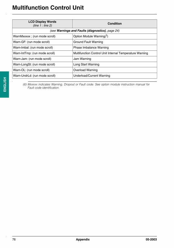
Multifunction Control UnitE
NG
LIS
H
(6) Mxxxxx indicates Warning, Dropout or Fault code. See option module instruction manual forFault code identification.
(see Warnings and Faults (diagnostics), page 24)
WarnMxxxxx ; (run mode scroll) Option Module Warning(5)
Warn-GF: (run mode scroll) Ground Fault Warning
Warn-Imbal: (run mode scroll) Phase Imbalance Warning
Warn-IntTmp: (run mode scroll) Multifunction Control Unit Internal Temperature Warning
Warn-Jam: (run mode scroll) Jam Warning
Warn-LongSt: (run mode scroll) Long Start Warning
Warn-OL: (run mode scroll) Overload Warning
Warn-UndrLd: (run mode scroll) Underload/Current Warning
LCD Display Words(line 1 : line 2)
Condition
76 Appendix 05-2003

Multifunction Control Unit
EN
GL
ISH
Appendix C - Register data format
From 50 to 83, identification registers, read only
16-bit register
Bit Range UnitDefaultvalue
Information
50 to 63 (see LULC031 communication module user’s manual)
64 to 69 ASCII 0.15 to 0.6 A LUCMx6BL Catalog Number
0.35 to 1.4 A LUCM1xBL
1.25 to 5 A LUCM05BL
3 to 12 A LUCM12BL
4.5 to 18 A LUCM18BL
8 to 32 A LUCM32BL
70 to 73 LUCM••BL Serial reference
74 Reserved
75 0 0 - 1 Off/On 0 Unknown Control unit
1 0 - 1 Off/On 0 LUCA standard control unit
2 0 - 1 Off/On 0 LUCB/CC/CD advanced control unit
3 0 - 1 Off/On 0 Reserved
4 0 - 1 Off/On 1 LUCM••BL Multifunction Control Unit
76 1000 - 29999 LUCM••BL Firmware revision
77 1000 - 29999 0 LUCM••BL Compatibility revision
78 0 - 65535 0.1% 4000 Sensor Scale Ratio (max / min x1000)
79 0 - 65535 0,1 A 6 0.15 to 0.6 A Sensor maximum
14 0.35 to 1.4 A
50 1.25 to 5 A
120 3 to 12 A
180 4.5 to 18 A
320 8 to 32 A
80 0 0 - 1 Off/On 0 Power Base unknown
1 0 - 1 Off/On 0 Reserved
2 0 - 1 Off/On 0 Starter
3 0 - 1 Off/On 1 Contactor-breaker
4-15 0 - 1 Off/On 0 Reserved
81 0 - 65535 0,1 A 120 12 A Power Base Range
320 32 A
82 Reserved
83 Reserved
05-2003 Appendix 77

Multifunction Control UnitE
NG
LIS
H
From 100 to 277, statistics registers, read only
16-bit register
Bit Range UnitDefaultvalue
Information
100 0 - 65535 Quantity 0 Number Short Trips
101 0 - 65535 Quantity 0 Number Magnetic Trips
102 0 - 65535 Quantity 0 Number Ground Fault Trips
103 0 - 65535 Quantity 0 Number Thermal Trips
104 0 - 65535 Quantity 0 Number Long Start Trips
105 0 - 65535 Quantity 0 Number Jam Trips
106 0 - 65535 Quantity 0 Number Phase Imbal. Trips
108 0 - 65535 Quantity 0 Number Shunt Trips
109 0 - 65535 Quantity 0 Number Comm Loss Trips
110 0 - 65535 Quantity 0 Number LULC031 communication module Internal Faults
111 0 - 65535 Quantity 0 Number Module identification Faults
112 0 - 65535 Quantity 0 Number Module internal Faults
113 0 - 65535 Quantity 0 Number Module Trips
114 0 - 65535 Quantity 0 Number Module Dropouts
115 0 - 65535 Quantity 0 Number Auto Resets
116 0 - 65535 Quantity 0 Number Thermal Warnings
117 - 118 0-4.2 billion Quantity 0 Number of Starts
119 - 120 0-4.2 billion(136 years)
Seconds 0 Operating Time
121 0 - 200 Degrees C 0 Max Control unit Internal Temp
150 0 - 65535 None 0 Trip n-0 Fault Number
151 25 - 100 % FLA max 0 FLA Current Setting
152 0 - 100 % 0 Thermal Level
153 0 - 2,000 % FLA 0 IIAV Average Current
154 0 - 2,000 % FLA 0 IL1 Current
155 0 - 2,000 % FLA 0 IL2 Current
156 0 - 2,000 % FLA 0 IL3 Current
157 0 - 2,000 % FLA 0 IGF Current
180 0 - 65535 None 0 Trip n-1 Fault Number
181 25 - 100 % FLA max 0 FLA Current Setting
182 0 - 100 % 0 Thermal Level
183 0 - 2,000 % FLA 0 IIAV Average Current
184 0 - 2,000 % FLA 0 IL1 Current
185 0 - 2,000 % FLA 0 IL2 Current
78 Appendix 05-2003
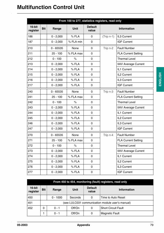
Multifunction Control Unit
EN
GL
ISH
186 0 - 2,000 % FLA 0 (Trip n-1) IL3 Current
187 0 - 2,000 % FLA min 0 IGF Current
210 0 - 65535 None 0 Trip n-2 Fault Number
211 25 - 100 % FLA max 0 FLA Current Setting
212 0 - 100 % 0 Thermal Level
213 0 - 2,000 % FLA 0 IIAV Average Current
214 0 - 2,000 % FLA 0 IL1 Current
215 0 - 2,000 % FLA 0 IL2 Current
216 0 - 2,000 % FLA 0 IL3 Current
217 0 - 2,000 % FLA 0 IGF Current
240 0 - 65535 None 0 Trip n-3 Fault Number
241 25 - 100 % FLA max 0 FLA Current Setting
242 0 - 100 % 0 Thermal Level
243 0 - 2,000 % FLA 0 IIAV Average Current
244 0 - 2,000 % FLA 0 IL1 Current
245 0 - 2,000 % FLA 0 IL2 Current
246 0 - 2,000 % FLA 0 IL3 Current
247 0 - 2,000 % FLA 0 IGF Current
270 0 - 65535 None 0 Trip n-4 Fault Number
271 25 - 100 % FLA max 0 FLA Current Setting
272 0 - 100 % 0 Thermal Level
273 0 - 2,000 % FLA 0 IIAV Average Current
274 0 - 2,000 % FLA 0 IL1 Current
275 0 - 2,000 % FLA 0 IL2 Current
276 0 - 2,000 % FLA 0 IL3 Current
277 0 - 2,000 % FLA 0 IGF Current
From 450 to 454, monitoring (fault) registers, read only
16-bit register
Bit Range UnitDefaultvalue
Information
450 0 - 1000 Seconds 0 Time to Auto Reset
451 (see LULC031 communication module user’s manual)
452 0 0 - 1 Off/On 0 Short Circuit Fault
1 0 - 1 Off/On 0 Magnetic Fault
From 100 to 277, statistics registers, read only
16-bit register
Bit Range UnitDefaultvalue
Information
05-2003 Appendix 79
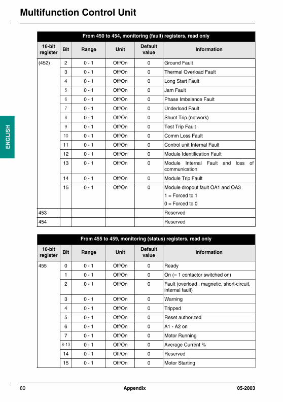
Multifunction Control UnitE
NG
LIS
H
(452) 2 0 - 1 Off/On 0 Ground Fault
3 0 - 1 Off/On 0 Thermal Overload Fault
4 0 - 1 Off/On 0 Long Start Fault
5 0 - 1 Off/On 0 Jam Fault
6 0 - 1 Off/On 0 Phase Imbalance Fault
7 0 - 1 Off/On 0 Underload Fault
8 0 - 1 Off/On 0 Shunt Trip (network)
9 0 - 1 Off/On 0 Test Trip Fault
10 0 - 1 Off/On 0 Comm Loss Fault
11 0 - 1 Off/On 0 Control unit Internal Fault
12 0 - 1 Off/On 0 Module Identification Fault
13 0 - 1 Off/On 0 Module Internal Fault and loss ofcommunication
14 0 - 1 Off/On 0 Module Trip Fault
15 0 - 1 Off/On 0 Module dropout fault OA1 and OA3
1 = Forced to 1
0 = Forced to 0
453 Reserved
454 Reserved
From 455 to 459, monitoring (status) registers, read only
16-bit register
Bit Range UnitDefaultvalue
Information
455 0 0 - 1 Off/On 0 Ready
1 0 - 1 Off/On 0 On (= 1 contactor switched on)
2 0 - 1 Off/On 0 Fault (overload , magnetic, short-circuit, internal fault)
3 0 - 1 Off/On 0 Warning
4 0 - 1 Off/On 0 Tripped
5 0 - 1 Off/On 0 Reset authorized
6 0 - 1 Off/On 0 A1 - A2 on
7 0 - 1 Off/On 0 Motor Running
8-13 0 - 1 Off/On 0 Average Current %
14 0 - 1 Off/On 0 Reserved
15 0 - 1 Off/On 0 Motor Starting
From 450 to 454, monitoring (fault) registers, read only
16-bit register
Bit Range UnitDefaultvalue
Information
80 Appendix 05-2003

Multifunction Control Unit
EN
GL
ISH
456 0 0 - 1 Off/On 0 Auto Resetting
1 0 - 1 Off/On 0 Motor Paused
2-15 0 - 1 Off/On 0 Reserved
457 (see LULC031 communication module user’s manual)
458 Reserved
459 Reserved
From 460 to 464, monitoring (warning) registers, read only
16-bit register
Bit Range UnitDefaultvalue
Information
460 0 - 65535 None Warning Number
461 0-1 0 - 1 Off/On Reserved
2 0 - 1 Off/On Ground Fault Warning
3 0 - 1 Off/On Thermal Warning
4 0 - 1 Off/On Long Start Warning
5 0 - 1 Off/On Jam Warning
6 0 - 1 Off/On Phase Imbalance Warning
7 0 - 1 Off/On Under Current Warning
8-9 0 - 1 Off/On Reserved
10 0 - 1 Off/On Comm Loss (485 port)
11 0 - 1 Off/On Control unit Internal Temperature
12 0 - 1 Off/On Module Identification Warning
13-14 0 - 1 Off/On Reserved
15 0 - 1 Off/On Module Warning
462 0 Reserved
463 0 Reserved
464 0 Reserved
From 465 to 599, monitoring (measurements) registers, read only
16-bit register
Bit Range UnitDefaultvalue
Information
465 0 - 100 % TripLevel Thermal Capacity Level
466 0 - 2,000 % FLA IIAV Average Current
467 0 - 2,000 % FLA IL1 Current
468 0 - 2,000 % FLA IL2 Current
From 455 to 459, monitoring (status) registers, read only
16-bit register
Bit Range UnitDefaultvalue
Information
05-2003 Appendix 81

Multifunction Control UnitE
NG
LIS
H
469 0 - 2,000 % FLA IL3 Current
470 0 - 2,000 % FLA min IGF Current
471 0 - 100 % IMB Phase Imbalance
472 -40 to +200 Degrees C Control unit Internal Temperature
473 0 - 65535 None 0 Configuration Checksum (Checksumrotate registers 600-699)
474 - 599 Reserved
From 600 to 626, configuration registers, read and write accessible if the starter is stopped
16-bit register
Bit Range UnitDefaultvalue
Information
600 0000 - 9999 4 digits 0000 Password
601 0 0 - 1 Off/On 1 Configuration Required
1 0 - 1 Off/On 0 Reserved
2 0 - 1 Off/On 1 TeSys® model U Power Base Type0 = Starter1 = Self protected starter
3 0 - 1 Off/On 0 Power Base size 12 Amp (on A1A2)
4 0 - 1 Off/On 0 Power Base size 32 Amp (on A1A2)
5 0 - 1 Off/On 0 Reserved
6-12 0 - 1 Off/On 0 Reserved
13 0 - 1 Off/On 1 3 Phase Motor
14 0 - 1 Off/On 0 1 Phase Motor
15 0 - 1 Off/On 0 Aux Fan Cooled
602 0 0 - 1 Off/On 1 Reset Mode - Manual
1 0 - 1 Off/On 0 Reset Mode - Remote/ Ent
2 0 - 1 Off/On 0 Reset Mode - Auto
3 0 - 1 Off/On 0 RS 485 Comms parity
4 0 - 1 Off/On 1 Enable Comms control
5 0 - 1 Off/On 1 RS 485 Watchdog Ignore
6 0 - 1 Off/On 0 RS 485 Watchdog Warning
7 0 - 1 Off/On 0 RS 485 Watchdog Dropout
8 0 - 1 Off/On 0 RS 485 Watchdog Trip
9 0 - 1 Off/On 0 RS 485 Watchdog Start (future)
10 0 - 1 Off/On 0 Pause on Power Up (future)
11-15 Reserved
From 465 to 599, monitoring (measurements) registers, read only
16-bit register
Bit Range UnitDefaultvalue
Information
82 Appendix 05-2003

Multifunction Control Unit
EN
GL
ISH
603 1 - 247 Address 1 Modbus slave address
604 1200, 4800, 9600, 19200
Baud 19200 Modbus Baud Rate
605 300 to 1700 % FLA 1420 Magnetic Trip
606 5, 10, 15, 20, 25, 30
Motor Class 5 Load Class
607 1 - 1000 Seconds 120 Thermal Reset Time
608 35 - 100 % Capacity 75 Thermal Reset Level
609 10 - 100 % Capacity 85 Thermal Warn Level
610 1 - 12 0.1 Sec. 10 Ground Fault Trip Time
611 20 - 500 % FLA min 30 Ground Fault Trip Level
612 20 - 500 % FLA min 30 Ground Fault Warn Level
613 2 - 200 0.1 Sec. 7 Phase Imbal. Trip Time Start
614 2 - 200 0.1 Sec. 50 Phase Imbal. Trip Time Run
615 10 - 30 % IMB 10 Phase Imbal. Trip Level
616 10 - 30 % IMB 10 Phase Imbal. Warn Level
617 1 - 30 Seconds 5 Jam Trip Time
618 100 - 800 % FLA 200 Jam Trip Level
619 100 - 800 % FLA 200 Jam Warn Level
620 1 - 200 Seconds 10 Underload Trip Time
621 30 - 100 % FLA 50 Underload Trip Level
622 30 - 100 % FLA 50 Underload Warn Level
623 1 - 200 Seconds 20 Long Start Trip Time
624 100 - 800 % FLA 100 Long Start Trip Level
625 100 - 800 % FLA 100 Long Start Warn Level
626 0 -255 None 128 Display Contrast
From 650 to 690, setting registers, read/write accessible
16-bit register
Bit Range UnitDefaultvalue
Information
650 0 0 - 1 Off/On 1 English
1 0 - 1 Off/On 0 Francais
2 0 - 1 Off/On 0 Español
3 0 - 1 Off/On 0 Deutsch
4 0 - 1 Off/On 0 Italiano
From 600 to 626, configuration registers, read and write accessible if the starter is stopped
16-bit register
Bit Range UnitDefaultvalue
Information
05-2003 Appendix 83
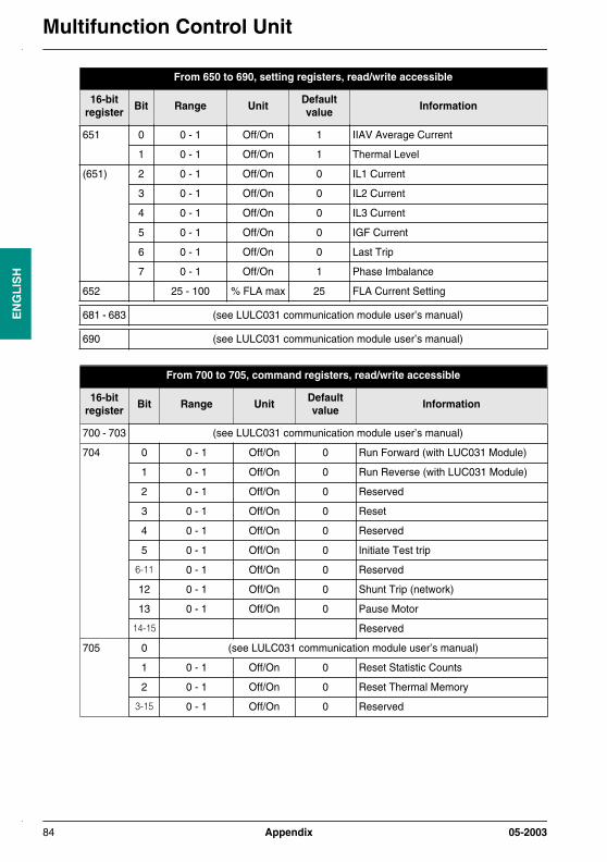
Multifunction Control UnitE
NG
LIS
H
651 0 0 - 1 Off/On 1 IIAV Average Current
1 0 - 1 Off/On 1 Thermal Level
(651) 2 0 - 1 Off/On 0 IL1 Current
3 0 - 1 Off/On 0 IL2 Current
4 0 - 1 Off/On 0 IL3 Current
5 0 - 1 Off/On 0 IGF Current
6 0 - 1 Off/On 0 Last Trip
7 0 - 1 Off/On 1 Phase Imbalance
652 25 - 100 % FLA max 25 FLA Current Setting
681 - 683 (see LULC031 communication module user’s manual)
690 (see LULC031 communication module user’s manual)
From 700 to 705, command registers, read/write accessible
16-bit register
Bit Range UnitDefaultvalue
Information
700 - 703 (see LULC031 communication module user’s manual)
704 0 0 - 1 Off/On 0 Run Forward (with LUC031 Module)
1 0 - 1 Off/On 0 Run Reverse (with LUC031 Module)
2 0 - 1 Off/On 0 Reserved
3 0 - 1 Off/On 0 Reset
4 0 - 1 Off/On 0 Reserved
5 0 - 1 Off/On 0 Initiate Test trip
6-11 0 - 1 Off/On 0 Reserved
12 0 - 1 Off/On 0 Shunt Trip (network)
13 0 - 1 Off/On 0 Pause Motor
14-15 Reserved
705 0 (see LULC031 communication module user’s manual)
1 0 - 1 Off/On 0 Reset Statistic Counts
2 0 - 1 Off/On 0 Reset Thermal Memory
3-15 0 - 1 Off/On 0 Reserved
From 650 to 690, setting registers, read/write accessible
16-bit register
Bit Range UnitDefaultvalue
Information
84 Appendix 05-2003
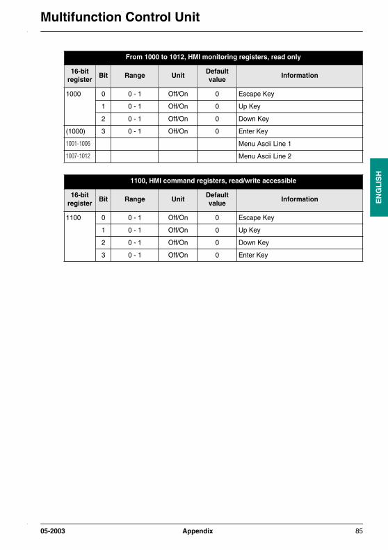
Multifunction Control Unit
EN
GL
ISH
From 1000 to 1012, HMI monitoring registers, read only
16-bit register
Bit Range UnitDefaultvalue
Information
1000 0 0 - 1 Off/On 0 Escape Key
1 0 - 1 Off/On 0 Up Key
2 0 - 1 Off/On 0 Down Key
(1000) 3 0 - 1 Off/On 0 Enter Key
1001-1006 Menu Ascii Line 1
1007-1012 Menu Ascii Line 2
1100, HMI command registers, read/write accessible
16-bit register
Bit Range UnitDefaultvalue
Information
1100 0 0 - 1 Off/On 0 Escape Key
1 0 - 1 Off/On 0 Up Key
2 0 - 1 Off/On 0 Down Key
3 0 - 1 Off/On 0 Enter Key
05-2003 Appendix 85
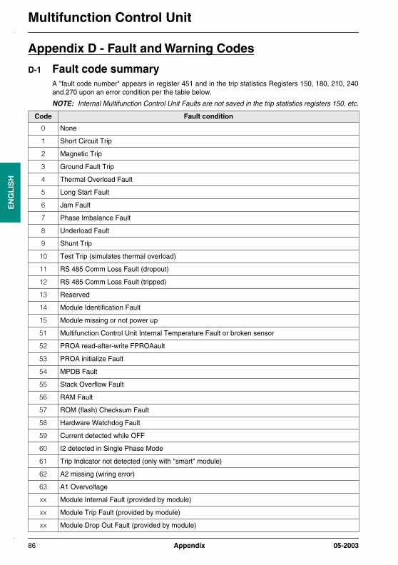
Multifunction Control UnitE
NG
LIS
H
Appendix D - Fault and Warning Codes
D-1 Fault code summaryA "fault code number" appears in register 451 and in the trip statistics Registers 150, 180, 210, 240and 270 upon an error condition per the table below.
NOTE: Internal Multifunction Control Unit Faults are not saved in the trip statistics registers 150, etc.
Code Fault condition
0 None
1 Short Circuit Trip
2 Magnetic Trip
3 Ground Fault Trip
4 Thermal Overload Fault
5 Long Start Fault
6 Jam Fault
7 Phase Imbalance Fault
8 Underload Fault
9 Shunt Trip
10 Test Trip (simulates thermal overload)
11 RS 485 Comm Loss Fault (dropout)
12 RS 485 Comm Loss Fault (tripped)
13 Reserved
14 Module Identification Fault
15 Module missing or not power up
51 Multifunction Control Unit Internal Temperature Fault or broken sensor
52 PROA read-after-write FPROAault
53 PROA initialize Fault
54 MPDB Fault
55 Stack Overflow Fault
56 RAM Fault
57 ROM (flash) Checksum Fault
58 Hardware Watchdog Fault
59 Current detected while OFF
60 I2 detected in Single Phase Mode
61 Trip Indicator not detected (only with "smart" module)
62 A2 missing (wiring error)
63 A1 Overvoltage
xx Module Internal Fault (provided by module)
xx Module Trip Fault (provided by module)
xx Module Drop Out Fault (provided by module)
86 Appendix 05-2003

Multifunction Control Unit
EN
GL
ISH
D-2 Warning code summaryA "warning code number" appears in register upon a warning condition per the table below.
NOTE: Internal Multifunction Control Unit Faults are not saved in the trip statistics registers 150, etc.
Code Fault condition
0 None
1 Reserved
2 Reserved
3 Ground Fault Warning
4 Thermal Overload Warning
5 Long Start Warning
6 Jam Warning
7 Phase Imbalance Warning
8 Underload Fault Underload Warning
9 Reserved
10 RS 485 Communication Loss Warning
11 Multifunction Control Unit Internal Temperature Warning
12 Module Identification Warning
13 Reserved
xx Multifunction Control Unit Warning (provided by module)
05-2003 Chapter 1 - General information 87
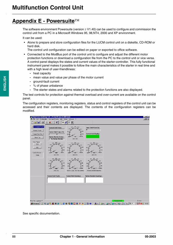
Multifunction Control UnitE
NG
LIS
H
Appendix E - PowersuiteThe software environment Powersuite (version ≥ V1.40) can be used to configure and commission thecontrol unit from a PC in a Microsoft Windows 95, 98,NT4, 2000 and XP environment.
It can be used:
• Alone to prepare and store configuration files for the LUCM control unit on a diskette, CD-ROM or hard disk.The control unit configuration can be edited on paper or exported to office software.
• Connected to the ModBus port of the control unit to configure and adjust the different motor protection functions or download a configuration file from the PC to the control unit or vice versa.A control panel displays the states and current values of the starter-controller. This fully functional instrument panel makes it possible to follow the main characteristics of the starter in real time and with a high level of user-friendliness:
- heat capacity- mean value and value per phase of the motor current- ground-fault current - % of phase unbalance- The starter states and alarms related to the protection functions are also displayed.
The test controls for protection against thermal overload and over-current are available on the controlpanel.
The configuration registers, monitoring registers, status and control registers of the control unit can beaccessed and their contents are displayed. The contents of the configuration registers can bemodified.
See specific documentation.
88 Chapter 1 - General information 05-2003

DIA1ED3030203EN 05-2003


![contactores - telemecanique[1]](https://img.dokumen.tips/doc/110x75/557211ba497959fc0b8f6927/contactores-telemecanique1.jpg)