Embed Size (px)
Citation preview

We Make WiMAX Easy
WH
ITE
PA
PE
R
WHITE PAPER
TDD and FDD Wireless Access Systems
Coexistence of TDD and FDD
Wireless Access Systems
In the 3.5GHz Band
4Gon www.4Gon.co.uk [email protected] Tel: +44 (0)1245 808295 Fax: +44 (0)1245 808299
WH
ITE
PA
PE
R
TDD and FDD Wireless Access Systems
TDD and FDD Wireless Access Systems
Coexistence of TDD and FDD
Wireless Access Systems
In the 3.5GHz Band
CONTENTS
Introduction 2
Frequency Division Duplexing (FDD) System 3
Time Division Duplex Systems 5
Airspan Study into Co-existence of TDD and FDD systems 6
Methodology for BS-BS Interference analysis 7
Methodology for MS/SS-SS Interference analysis 13
Conclusions of the study 15
Summary 16
Copyright Airspan Networks Inc. 2007
4Gon www.4Gon.co.uk [email protected] Tel: +44 (0)1245 808295 Fax: +44 (0)1245 808299

WH
ITE
PA
PE
R
TDD and FDD Wireless Access Systems
Several million lines of proprietary Wireless Local Loop (WLL)
systems are in service around the world. The outstanding sub-
10GHz licensed band for WLL deployment is the 3.4GHz-3.6GHz
band commonly referred to as the 3.5GHz band. In most
countries that follow the ETSI recommendations, the licensing
regime and therefore the systems deployments in this band have
followed the Frequency Division Duplex (FDD) method.
With the arrival of the IEEE 802.16 standard, wireless access is a
more credible technology then ever before for bringing, in an
economically viable manner, both fixed and mobile broadband
solutions to millions of customers all over the world. The WiMAX
Forum has defined ‘Fixed’ WiMAX profiles with both FDD and
Time Division Duplex (TDD); whereas the currently defined
‘Mobile’ WiMAX profiles are in TDD only.
It is well known that introducing TDD systems into the same
spectral and geographic space as FDD systems can be problematic
and requires careful RF engineering. Therefore, Airspan has
undertaken an extensive study in order to establish the
boundaries of the TDD / FDD coexistence issues in the 3.5GHz
band, the results of which are summarised in this white paper.
Please consult the Airspan Web-site (www.airspan.com) for
further details about Airspan’s WiMAX products and solutions.
1
Copyright Airspan Networks Inc. 2007
4Gon www.4Gon.co.uk [email protected] Tel: +44 (0)1245 808295 Fax: +44 (0)1245 808299

WH
ITE
PA
PE
R
TDD and FDD Wireless Access Systems
Introduction
During the last decade several million lines of proprietary Wireless Local Loop (WLL)products have been deployed around the world to provide customers with telephony,data and Internet access services. With the arrival in 2004 of the IEEE 802.16standard for wide area wireless access, interest in wireless access is keener than everbefore. WiMAX, championed by the WiMAX Forum to promote conformance andinteroperability of the IEEE 802.16 standard, has revolutionised the wide areabroadband wireless communications. The latest version of the standard, IEEE802.16e-2005, extents the earlier specifications in order to address the requirementsof both mobile and fixed WiMAX deployments.
Wireless access systems are deployed in both licensed and unlicensed bands.Operators prefer to deploy in licensed bands in order to deliver better quality serviceswithout suffering from arbitrary interference problems that may be experienced inunlicensed bands. Of all the sub-10GHz bands used for wireless access, by far themost popular is the 3.5GHz band, which covers from 3.4GHz to 3.6GHz. It is alicensed band and in most ETSI countries it is licensed for Frequency DivisionDuplexing (FDD) operation. There are exceptions to this; in some countries it ispermissible to deploy Time Division Duplexing (TDD) systems in the 3.5GHz band.
For many years FDD and TDD have been the two methods of choice for handlinguplink (UL) and downlink (DL) transmissions in wireless systems. FDD uses twodifferent frequencies for the UL and DL thereby separating them in frequencywhereas TDD utilises a single frequency for both UL and DL signals and separatesthem in time.
In 2004 WiMAX Forum, in consultation with operators and vendors, defined a numberof profiles in the 3.5GHz band that specify both FDD and TDD duplexing methods,examples of which are 3.5F1 and 3.5T1 profiles. The first profiles defined for ‘Mobile’WiMAX support only TDD which means that in the future we will see an increasingnumber of TDD systems deployed in the 3.5GHz band as well as in other bands.
As we will explain later on in this paper, the FDD and TDD systems operate indifferent ways, as a result of which coexistence of FDD and TDD systems in the samespectral and/or geographic space could cause interference problems betweensystems, which need to be carefully managed. Interference is caused by one systemtransmitting whilst the other system is receiving in an adjacent band. Base stationsare particularly susceptible to interference from other base stations but interferencecan also be caused by a mobile station belonging to one system interfering with thebase station of another system.
In this paper we explore the issues arising from introducing TDD systems intoenvironments where there are already established networks of pre-WiMAX or WiMAXequipment based on FDD, and offer some guidance and solutions.
2
Copyright Airspan Networks Inc. 2007
4Gon www.4Gon.co.uk [email protected] Tel: +44 (0)1245 808295 Fax: +44 (0)1245 808299

WH
ITE
PA
PE
R
TDD and FDD Wireless Access Systems
Frequency Division Duplexing (FDD) System
In FDD systems UL and DL transmissions are allocated separate frequency bands. TheUL and DL channels are grouped into contiguous blocks of paired channels as shownin Figure 1. The paired UL and DL channels are typically separated by 100MHz.Thanks to the guard band between UL and DL, the interference of one FDD systemwith another is minimised.
Figure 1 – Spectrum allocation in FDD systems
Advantages of FDD Systems
Simultaneous and continuous UL and DL transmission
FDD systems provide full duplex operation making them ideal for applications such asvoice, where the UL and DL traffic requirements are more or less symmetrical.Moreover, continuous transmissions help reduce layer 2 (MAC) delays by enablingimmediate feedback to be provided about channel conditions.
Immunity to system interference
Thanks to a large separation between UL and DL, Base Station (BS) to BS andSubscriber Station (SS) to SS interferences are minimised and are negligibly small.
Ease of network planning
Since the BS-BS interference is kept to a minimum, network radio planning is easierfor FDD systems.
Disadvantages of FDD Systems
Fixed channel allocation
In FDD the UL and DL channel allocations are fixed. Whilst this provides benefits forsymmetric traffic, it can result in wasted bandwidth when the applications are
3
Copyright Airspan Networks Inc. 2007
Uplink Downlink
Guard Band
UL-DL Separation: 100MHz
4Gon www.4Gon.co.uk [email protected] Tel: +44 (0)1245 808295 Fax: +44 (0)1245 808299

WH
ITE
PA
PE
R
TDD and FDD Wireless Access Systems
asymmetric. As data traffic and Internet access become the dominant users ofbandwidth the need for flexible channel utilisation becomes more important.
Guard Band
FDD requires a guard band to separate the UL and DL channels.
Higher hardware costs
FDD requires a transmitter, a separate receiver and a diplexer. Furthermore, sharp RFfilters are required to isolate the UL and DL. These higher costs can be justified at thebase stations but at the subscriber stations often half duplex FDD (H-FDD) solutionsare used in order to keep the costs low.
Time Division Duplex Systems
A TDD system does not require paired frequency channels for UL and DL nor does itrequire a guard band. Instead TDD systems use the same channel for UL and DLtransmission separating them in the time domain. Each channel consists of one DLand one UL sub-frame as illustrated in Figure 2. TDD systems use guard intervalsbetween the transition from DL to UL and from UL to DL. These guard intervals arecalled Transmit/receive Transition Gap (TTG) and Receive/transmit Transition Gap(RTG). Generally TTG is larger than RTG in order to allow time for the round-tripdelay of the signals from the edge of the sector.
Figure 2 – TDD structure
4
Copyright Airspan Networks Inc. 2007
One channel for both UL and DL
TTG TTGRTG
4Gon www.4Gon.co.uk [email protected] Tel: +44 (0)1245 808295 Fax: +44 (0)1245 808299
WH
ITE
PA
PE
R
TDD and FDD Wireless Access Systems
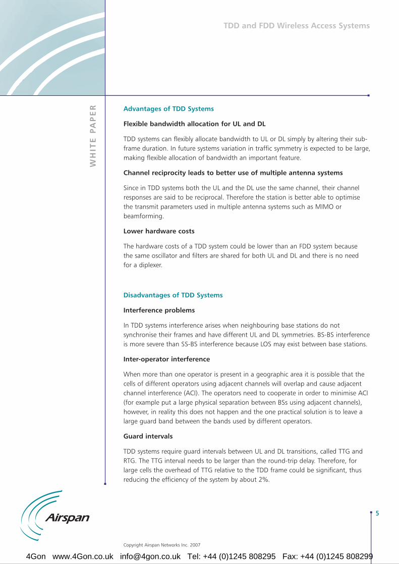
Advantages of TDD Systems
Flexible bandwidth allocation for UL and DL
TDD systems can flexibly allocate bandwidth to UL or DL simply by altering their sub-frame duration. In future systems variation in traffic symmetry is expected to be large,making flexible allocation of bandwidth an important feature.
Channel reciprocity leads to better use of multiple antenna systems
Since in TDD systems both the UL and the DL use the same channel, their channelresponses are said to be reciprocal. Therefore the station is better able to optimisethe transmit parameters used in multiple antenna systems such as MIMO orbeamforming.
Lower hardware costs
The hardware costs of a TDD system could be lower than an FDD system because the same oscillator and filters are shared for both UL and DL and there is no need for a diplexer.
Disadvantages of TDD Systems
Interference problems
In TDD systems interference arises when neighbouring base stations do notsynchronise their frames and have different UL and DL symmetries. BS-BS interferenceis more severe than SS-BS interference because LOS may exist between base stations.
Inter-operator interference
When more than one operator is present in a geographic area it is possible that thecells of different operators using adjacent channels will overlap and cause adjacentchannel interference (ACI). The operators need to cooperate in order to minimise ACI(for example put a large physical separation between BSs using adjacent channels),however, in reality this does not happen and the one practical solution is to leave alarge guard band between the bands used by different operators.
Guard intervals
TDD systems require guard intervals between UL and DL transitions, called TTG andRTG. The TTG interval needs to be larger than the round-trip delay. Therefore, forlarge cells the overhead of TTG relative to the TDD frame could be significant, thusreducing the efficiency of the system by about 2%.
5
Copyright Airspan Networks Inc. 2007
4Gon www.4Gon.co.uk [email protected] Tel: +44 (0)1245 808295 Fax: +44 (0)1245 808299

WH
ITE
PA
PE
R
TDD and FDD Wireless Access Systems
Airspan Study into Co-existence of TDD and FDD systems
Since 1992 Airspan has been a leading provider of wireless access solutions. TodayAirspan has more than 400 customers in over 100 countries and has shipped morethan 1 million lines of wireless access. In 2005 Airspan started shipping its FixedWiMAX solutions as well as its widely used proprietary solutions. Today Airspan hasWiMAX commercial deployments and trials with more than 80 customers. As weprepare to bring to market our TDD based IEEE 802.16e-2005 solutions it isimportant that we fully understand the co-existence issues between proprietary andWiMAX products and between TDD and FDD, so that we can plan network solutionsin a professional way.
For these reasons Airspan has undertaken an extensive study of the following co-existence scenarios:
1 Interference Analysis between Base Stations
a) Mobile WiMAX TDD BS and Proprietary FDD BSb) Mobile WiMAX TDD BS and Fixed WiMAX FDD BS
2 Interference Analysis between Subscriber/Mobile Stations
a) Mobile WiMAX TDD Mobile Station (MS) and Proprietary FDD Subscriber Station (SS)
b) Mobile WiMAX TDD MS and Fixed WiMAX FDD SS
We did not study the interference scenarios between two TDD base stations orbetween two FDD base stations because the solutions to these are well understood.For completeness these are summarised below:
The interference between two TDD base stations can arise due to two main reasons: cross-slot co-channel interference and interoperator adjacent channelinterference (ACI). Cross-slot co-channel interference can be solved by synchronisingthe base stations and by the careful use of sectorised antennas. However,synchronisation is not seen as a practical way of managing interoperator ACI.Instead, ACI can be reduced by using very sharp RF filters, which is expensive, or amore practical approach is to assign large guard bands between the bands used by different operators.
The interference between two FDD base stations can be managed relatively easilythanks to the large separation between the UL and DL channels of FDD systems.
6
Copyright Airspan Networks Inc. 2007
4Gon www.4Gon.co.uk [email protected] Tel: +44 (0)1245 808295 Fax: +44 (0)1245 808299

WH
ITE
PA
PE
R
TDD and FDD Wireless Access Systems
7
Methodology for BS-BS Interference analysis
The methodology we have used to study the interference scenarios mentioned aboveis summarised here.
First we established the system characteristics for the base stations we want to study.We defined the system characteristics for Mobile WiMAX TDD BS, for the FixedWiMAX FDD BS and for the Proprietary FDD BS based on the system parameters ofour products.
We then developed co-existence scenarios to calculate interference levels as afunction of interferer/victim separation distances. Scenarios considered include:
• Interference from a Mobile WiMAX TDD BS into a Proprietary FDD BS
• Interference from a Mobile WiMAX TDD BS into a Fixed WiMAX FDD BS
• Interference from a Proprietary FDD BS into a Mobile WiMAX TDD BS
• Interference from a Fixed WiMAX FDD BS into a Mobile WiMAX TDD BS
We studied the implications of the interfering and victim BSs operating on the sametower and on opposite towers. The analysis consisted of two steps, the derivation ofthe Net Filter Discrimination (NFD) and the analysis of the impact of ReceiverBlocking.
The first step of the analysis is the derivation of the Net Filter Discrimination (NFD),which specifies the amount of suppression available as a function of frequency offsetbetween the interferer and victim receiver. The NFD calculation is based on series ofcalculations using interferer emission and victim receiver selectivity masks. The NFDmethod is fully detailed in Reference 1. In our study, the method was applied bysliding the interferer emission mask across the victim receiver selectivity mask step bystep. The NFD level at each step is then calculated using the amount of overlapbetween the masks.
For the scenarios where the interfering and victim BS antennas are assumed to beoperating on the same tower, the additional suppression required to bring theinterference to an acceptable level is calculated using the interfering BS transmitpower, the maximum achievable isolation between the antennas and the victim BSinterference criterion. The additional suppression is then compared against the NFDlevels. The frequency offset at which the calculated additional suppression is equal tothe NFD level is the required guard band.
Copyright Airspan Networks Inc. 2007
4Gon www.4Gon.co.uk [email protected] Tel: +44 (0)1245 808295 Fax: +44 (0)1245 808299
WH
ITE
PA
PE
R
TDD and FDD Wireless Access Systems
For the scenarios where the interfering and victim BS antennas are assumed to beoperating on opposite towers, the additional suppression required to bring theinterference to an acceptable level is calculated using the interfering BS transmitpower, the interfering and victim BS antenna gains, the path loss corresponding tothe distance between the interfering and victim BS and the victim BS interferencecriterion. The additional suppression is then compared against the NFD levels. Thefrequency offset at which the calculated additional suppression is equal to the NFDlevel is the required guard band.
The second step of the analysis examines the impact of receiver blocking using same-tower and opposite-towers scenarios. In the case of a same-tower scenario, theadditional suppression required to prevent front-end saturation is calculated from theinterfering BS transmit power and the victim BS receiver blocking level. Thecalculated additional suppression is then compared against the maximum achievableisolation between the interfering and victim antennas to identify if the co existenceon the same tower is possible without the risk of the victim BS being blocked.
In the case of an opposite-towers scenario, the required isolation is calculated fromthe interfering BS transmit power, the interfering and victim BS antenna gains andthe victim BS receiver blocking level. The calculated isolation is then translated into aminimum separation distance between the interfering BS and the victim BS. This isthe minimum distance at which the interference power is less than the victim BSreceiver blocking level. In all opposite-tower scenarios, the free-space model is usedto calculate interference path losses.
For a particular scenario to be feasible both the NFD analysis and the ReceiverBlocking analysis must be feasible.
In this white paper we do not intend to present and discuss each and every result ofthe extensive study but we will give an example, generalise the findings and drawconclusions.
8
Copyright Airspan Networks Inc. 2007
4Gon www.4Gon.co.uk [email protected] Tel: +44 (0)1245 808295 Fax: +44 (0)1245 808299

WH
ITE
PA
PE
R
TDD and FDD Wireless Access Systems
Example: Interference from Mobile WiMAX TDD (5MHz) BS intoa Proprietary FDD BS
NFD Analysis
The NFD graph shown in Figure 3 is derived with respect to the frequency separationbetween carrier centre frequencies using the TDD Mobile WiMAX BS (5 MHz)emission mask and the FDD Proprietary WLL BS receiver selectivity mask.
Figure 3 – NFD Graph
The separation between the Mobile WiMAX TDD BS and Proprietary FDD BS carriercentre frequencies is:
Mobile WiMAX TDD Channel Bandwidth of 5 MHz / 2 + Proprietary FDD Channel Bandwidth of 0.3072 / 2 = 2.6536 MHz
Identifying this value on the NFD graph shows the discrimination that is achievedwhen there is no guard band, which is approximately 23 dB.
Using the NFD graph we can draw conclusions about the separation and suppressionrequirements for same tower or opposite tower operation. Considering same toweroperation for example, the maximum suppression available in the NFD graph is 62.45dB, which corresponds to the carrier centre frequency separation of 10.14 MHz,hence a guard band of approximately 7.5 MHz.
Assuming that the interfering and victim antennas are on opposite towers andpointing away from each other (i.e. backlobe-to-backlobe alignment) the guard bandvalues shown in Figure 4 are calculated as a function of the distance betweeninterfering and victim BSs.
9
Copyright Airspan Networks Inc. 2007
4Gon www.4Gon.co.uk [email protected] Tel: +44 (0)1245 808295 Fax: +44 (0)1245 808299
WH
ITE
PA
PE
R
TDD and FDD Wireless Access Systems
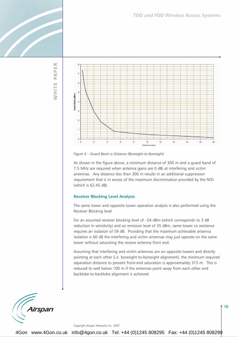
Figure 4 – Guard Band vs Distance (Boresight-to-Boresight)
As shown in the figure above, a minimum distance of 300 m and a guard band of7.5 MHz are required when antenna gains are 0 dBi at interfering and victimantennas. Any distance less than 300 m results in an additional suppressionrequirement that is in excess of the maximum discrimination provided by the NFD(which is 62.45 dB).
Receiver Blocking Level Analysis
The same tower and opposite tower operation analysis is also performed using theReceiver Blocking level.
For an assumed receiver blocking level of –24 dBm (which corresponds to 3 dBreduction in sensitivity) and an emission level of 35 dBm, same-tower co existencerequires an isolation of 59 dB. Providing that the maximum achievable antennaisolation is 60 dB the interfering and victim antennas may just operate on the sametower without saturating the receive antenna front end.
Assuming that interfering and victim antennas are on opposite towers and directlypointing at each other (i.e. boresight-to-boresight alignment), the minimum requiredseparation distance to prevent front-end saturation is approximately 315 m. This isreduced to well below 100 m if the antennas point away from each other andbacklobe-to-backlobe alignment is achieved.
10
Copyright Airspan Networks Inc. 2007
4Gon www.4Gon.co.uk [email protected] Tel: +44 (0)1245 808295 Fax: +44 (0)1245 808299

WH
ITE
PA
PE
R
TDD and FDD Wireless Access Systems
The receiver blocking level analysis results suggest that blocking requirements aresignificantly less stringent than those obtained from the analysis with the emissionand receiver selectivity masks. However, for a particular co-existence scenario to besuccessful both requirements must be met.
The Impact of Additional RF filtering
We repeated the above analysis assuming that the system is now implemented usingadditional RF filtering in the Mobile TDD system. Figure 5 shows the NFD graphswith and without transmit RF filters.
Figure 5 – NFD graphs with and without RF filters
The NFD plots show that when the transmitter RF filter is used the availablediscrimination is increased from 23 dB to 26 dB for the scenario where transmit and receive carriers are next to each other with no guard band in between. Inaddition, with the transmit RF filter, the maximum available discrimination is 99.15dB corresponding to a guard band of 5.85 MHz, instead of the 7.5MHz without the RF filter.
11
Copyright Airspan Networks Inc. 2007
4Gon www.4Gon.co.uk [email protected] Tel: +44 (0)1245 808295 Fax: +44 (0)1245 808299

WH
ITE
PA
PE
R
TDD and FDD Wireless Access Systems
The use of transmit RF filtering also improves the Guard band vs distance graph asshown in Figure 6.
Figure 6 – Guard band vs. Distance (Boresight-to-Boresight)
The plot shows that when the transmit RF filtering is used a minimum separation of210 metres and a guard band of 5.85 MHz meet the interference criterion in thepresence of interference from a single carrier. A one-channel guard band (i.e. 5MHz) ensures that the minimum separation requirement is 220 metres.
12
Copyright Airspan Networks Inc. 2007
4Gon www.4Gon.co.uk [email protected] Tel: +44 (0)1245 808295 Fax: +44 (0)1245 808299
WH
ITE
PA
PE
R
TDD and FDD Wireless Access Systems
Methodology for MS/SS-SS Interference analysis
We have also studied the impact of interference between subscriber stations. AMonte Carlo simulator was developed to model interference between subscriberstations. The simulator aggregates emissions from randomly located interferers at arandomly located victim receiver. Results are presented in the form of ‘percentage oflocations for which a given level of C/(N+I) is exceeded’. Simulations were created forcases where the base stations are co-located and where they are separated.
Example – Interference from TDD Mobile WiMAX SS into FDD Proprietary WLL SS
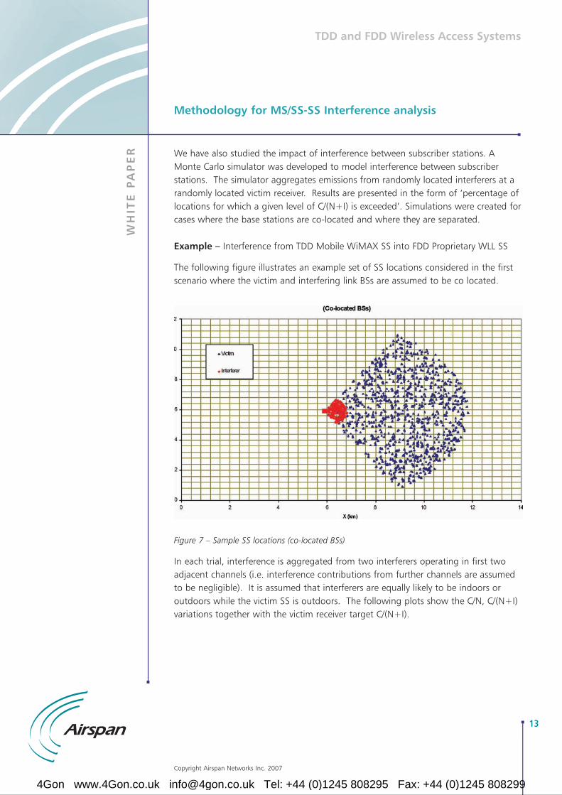
The following figure illustrates an example set of SS locations considered in the firstscenario where the victim and interfering link BSs are assumed to be co located.
Figure 7 – Sample SS locations (co-located BSs)
In each trial, interference is aggregated from two interferers operating in first twoadjacent channels (i.e. interference contributions from further channels are assumedto be negligible). It is assumed that interferers are equally likely to be indoors oroutdoors while the victim SS is outdoors. The following plots show the C/N, C/(N+I)variations together with the victim receiver target C/(N+I).
13
Copyright Airspan Networks Inc. 2007
4Gon www.4Gon.co.uk [email protected] Tel: +44 (0)1245 808295 Fax: +44 (0)1245 808299

WH
ITE
PA
PE
R
TDD and FDD Wireless Access Systems
Figure 8 - C/(N+I) (Co-located BSs)
Detailed results suggest that the target C/(N+I) is exceeded at 98.44% of locationswhen there is no interferer and 98.29% of locations when two interferers operate inadjacent bands with no guard band. Therefore, the percentage of receivers affectedby interference is 0.15%. It should be noted that when there is no guard bandpresent, the NFD levels are 23 dB and 53.6 dB for the first and second interferingadjacent channels, respectively.
When the same analysis is carried out for separated interferer and victim link basestations the results are very similar.
14
Copyright Airspan Networks Inc. 2007
4Gon www.4Gon.co.uk [email protected] Tel: +44 (0)1245 808295 Fax: +44 (0)1245 808299

WH
ITE
PA
PE
R
TDD and FDD Wireless Access Systems
Conclusions of the study
The analysis of adjacent band interference between base stations of systems usingTDD and FDD has shown that the co-existence in the same geographic area requiresthe use of additional front-end RF filtering as well as substantial guard bandsbetween the FDD and TDD systems.
Figure 9 – Guard Bands between FDD and TDD systems
When there is a boresight-to-boresight alignment between the victim and interferingantennas separation distances can be in the order of kilometres (for a guard band of5 MHz) unless front-end RF filters are used to reduce separation distances to fewhundred metres for the same guard band. In addition, these measures also makesame tower operation possible.
The analysis of adjacent band interference between subscriber stations of systemsusing TDD and FDD has shown that the co-existence requirements are not nearly asstringent as those calculated for base stations. In most scenarios, potential receiverlocations affected by adjacent band interference remain below 0.5% with no guardband between the victim and interfering subscriber terminals.
Utilising the Guard Band
As shown in Figure 9 above, having adequate guard bands between FDD and TDDsystems is a must in order to control interferences between the systems. However,wireless spectrum is a precious commodity and wasting spectrum should be avoidedif at all possible.
Figure 10 – Hybrid FDD deployment in the guard bands
Airspan’s HiperMAX base station family addresses and solves this issue by providing aHybrid FDD (HFDD) solution, which can be deployed in the guard bands, as shown inFigure 10.
HiperMAX HFDD solution co-exists with both the TDD and the FDD systems thatoperate in either side of it. This is achieved by synchronising its UL and DLtransmissions with the TDD system. Since it uses separate channels for UL and DLtransmissions in the same way as an FDD system, interference with other co-locatedFDD systems are also eliminated.
For more information about the HiperMAX base stations please visit Airspan’s website (www.airspan.com).
15
Copyright Airspan Networks Inc. 2007
FDD System Guard Band TDD System Guard Band FDD System
FDD System HFDD System TDD System HFDD System FDD System
4Gon www.4Gon.co.uk [email protected] Tel: +44 (0)1245 808295 Fax: +44 (0)1245 808299

WH
ITE
PA
PE
R
TDD and FDD Wireless Access Systems
Summary
Over the past decade millions of lines of wireless access systems using the FDDduplexing method have been deployed around the world. With the imminent arrivalof the TDD based Mobile WiMAX systems it is more important than ever before tounderstand the co-existence issues between FDD and TDD systems.
To this end Airspan has undertaken an in-depth study to fully understand the co-existence issues between TDD based Mobile WiMAX systems and FDD based FixedWiMAX and proprietary systems. The knowledge gained from the study hascomplemented years of experience gained from deploying FDD and TDD systemsaround the world and has enabled Airspan to pinpoint and solve such co-existenceissues in its customers’ networks.
Airspan’s HiperMAX base station family offers a solution to the ‘wasted’ guard bandspectrum by implementing a Hybrid FDD solution that utilises the guard bandsbetween the TDD and FDD systems, thus ensuring optimum utilisation of thisprecious resource.
References:
1 ETSI Technical Report ETSI TR 101 854 [2]
2 ETSI EN 301 021 V1.6.1: Fixed Radio Systems; Point-to-multipoint Equipment; Time Division Multiple Access; Point-to-multipoint Digital Radio Systems in Frequency Bands in the Range3 – 11 GHz
3 ETSI TR 101 854 V1.3.1: Fixed Radio Systems; Point-to-point Equipment; Derivation of Receiver Interference Parameters Useful for Planning Fixed Service Point-to-point Systems Operating Different Equipment Classes and/or Capacities
16
Copyright Airspan Networks Inc. 2007
4Gon www.4Gon.co.uk [email protected] Tel: +44 (0)1245 808295 Fax: +44 (0)1245 808299


![1094 IEEE TRANSACTIONS ON WIRELESS ... - WordPress.com · an FDD system, rather than switch to TDD [18], [21], [22]. Transmission schemes and channel estimation for FDD based massive](https://img.dokumen.tips/doc/110x75/60066b2fbb5dc15dcc0fd752/1094-ieee-transactions-on-wireless-an-fdd-system-rather-than-switch-to-tdd.jpg)