Embed Size (px)
Citation preview
©Taco Catalog #: 300-9.6Supersedes: 04/16/12
Effective Date: 06/20/13Printed in USA
TC Series Pumps provide the ultimate in reliability and ease of installation for heating, air conditioning, pressure boosting, cooling water transfer, and water supply applications.Quiet, dependable and proven performance: that’s the TC Series
TC Series Single-Stage, Double SuctionVertical Split Case Pumps
Water Circulation Pumps & Circulators

Features & Benefits-2-
CasingCasing Cover AO RingWear RingImpellerShaftSeal ShaftO RingBearing HouseBearing SpacerNutBearing Cover BBelleville SpringBall BearingStuffing CoverPressure RingStuffing RingStuffing BushCasing Cover BO RingO RingSeal BushMechanical SealO RingSeal CoverBall BearingNutBearing Cover A
12345678910111213141516171819202122232425262728
1234
56789
10
11
12
13
19 20 21 22 23 24 25 26 27 28
14 15 16 17 18
Pump Casing • Cast Iron Standard Impeller • High-efficiency Double Suction Bronze Impeller • Stainless Steel Optional
Shaft • Carbon Steel Shaft • Stainless Steel Optional
Shaft Sleeve • Bronze or Stainless Steel • Replaceable Shaft Sleeves
Wear Ring • Bronze Replaceable Wear Ring
Mechanical Seal • Handles a wide range of applications with superior longevity • Carbon Rotating Element • Silicon Carbide Stationary Seat • Viton Elastomers
Drip Pan • Standard
Base • Weld Reinforced • Groutless
*Per Hydraulic Institute and ASHRAE the grouting of bases is always recommended.Groutless Base*Drip Pan Standard
-3-
Features & Benefits
350
300
250
200
150
100
0 50 100 150 200 250 300
TEMPERATURE (˚F)
MA
XIM
UM
TO
TA
L W
OR
KIN
GP
RE
SS
UR
E (
PS
I)
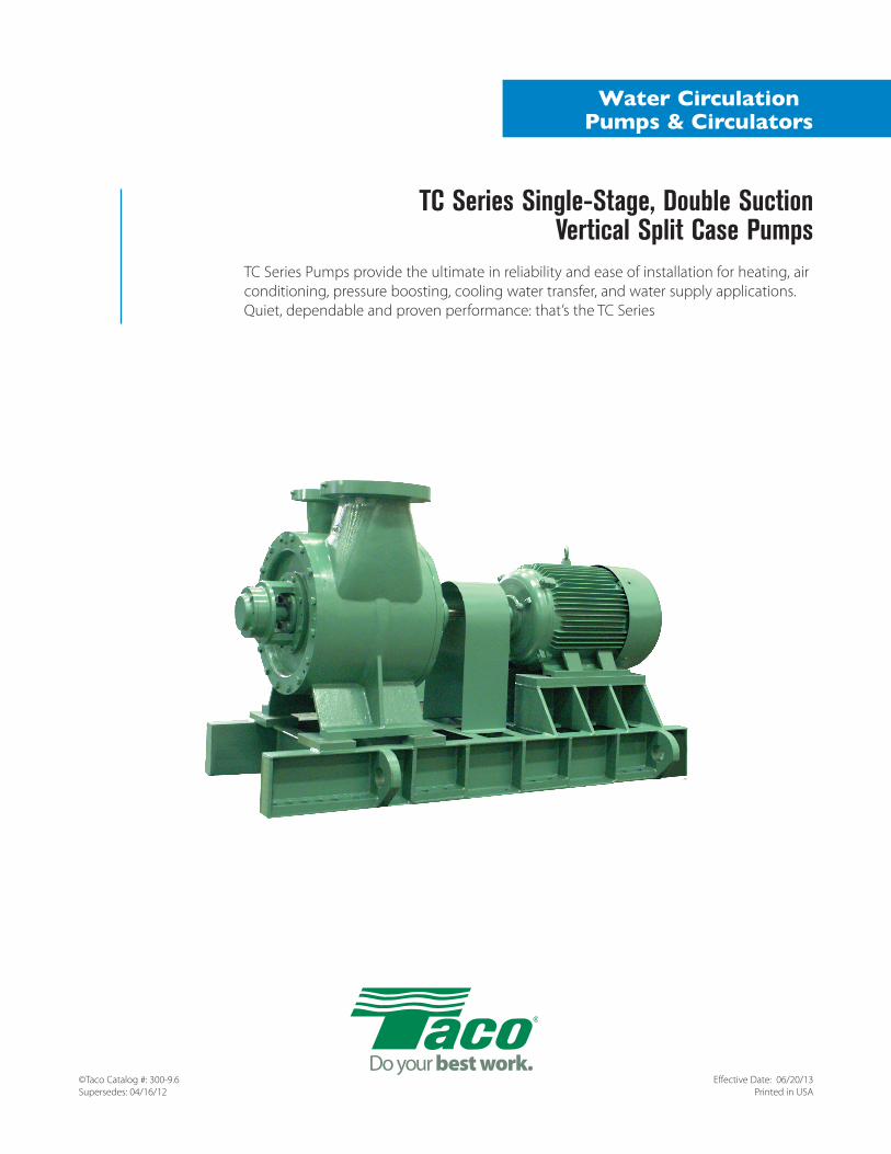
Class 250# in accordance with ANSI Standard B16.1
Class 125# in accordance with ANSI Standard B16.1
Materials of ConstructionOperating Specifications
Standard Optional
SNOITACIFICEPS GNITAREPO
Pressure-Temperature Ratings
ItemBronze Fitted All Iron
Standard Optional Standard Optional
-4-
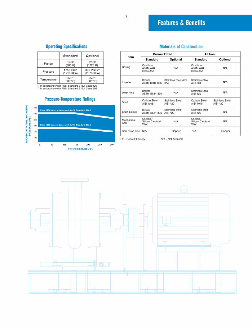
Part I – FundamentalsA centrifugal pump operated at constant speed delivers any capacity from zero to maximum depending on the head, design and suction conditions. Pump performance is most commonly shown by means of plotted curves which are graphical representations of a pump’s performance characteristics. Pump curves present the average results obtained from testing several pumps of the same design under standardized test conditions. For a single family residential application, considerations other than flow and head are of relatively little economic or functional importance, since the total load is small and the equipment used is relatively standardized. For many smaller circulators, only the flow and pressure produced are represented on the performance curve (Fig. 1-1).
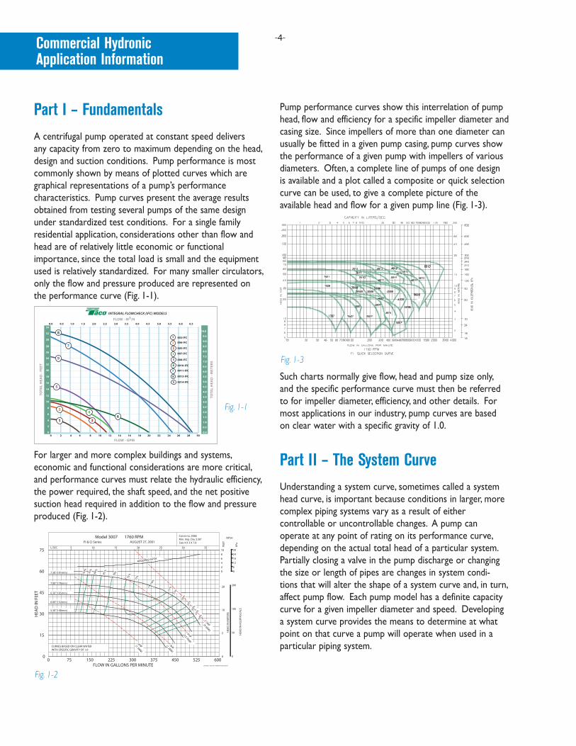
For larger and more complex buildings and systems, economic and functional considerations are more critical, and performance curves must relate the hydraulic efficiency, the power required, the shaft speed, and the net positive suction head required in addition to the flow and pressure produced (Fig. 1-2).
Pump performance curves show this interrelation of pump head, flow and efficiency for a specific impeller diameter and casing size. Since impellers of more than one diameter can usually be fitted in a given pump casing, pump curves show the performance of a given pump with impellers of various diameters. Often, a complete line of pumps of one design is available and a plot called a composite or quick selection curve can be used, to give a complete picture of the available head and flow for a given pump line (Fig. 1-3).
Such charts normally give flow, head and pump size only, and the specific performance curve must then be referred to for impeller diameter, efficiency, and other details. For most applications in our industry, pump curves are based on clear water with a specific gravity of 1.0.
Part II – The System CurveUnderstanding a system curve, sometimes called a system head curve, is important because conditions in larger, more complex piping systems vary as a result of either controllable or uncontrollable changes. A pump can operate at any point of rating on its performance curve, depending on the actual total head of a particular system. Partially closing a valve in the pump discharge or changing the size or length of pipes are changes in system condi-tions that will alter the shape of a system curve and, in turn, affect pump flow. Each pump model has a definite capacity curve for a given impeller diameter and speed. Developing a system curve provides the means to determine at what point on that curve a pump will operate when used in a particular piping system.
Commercial Hydronic Application Information
Fig. 1-1
10
20
10
JSA/MS 2-18-02 PC-2066 RevA ECN10627
CURVES BASED ON CLEAR WATERWITH SPECIFIC GRAVITY OF 1.0
5.50"(140mm)
0
2HP 3HP
5HP
5
7.5HP
6.00"(152mm)
6.50"(165mm)
7.00"(178mm)
7.50"(191mm)
5 10 15
REQUIRED NPSH
2
0
8
4
6
Size 4 X 3 X 7.0Min. Imp. Dia. 5.50"Curve no. 2066
20 25 30 35
0
50
100
200
6
0
24
12
18
30
77%75
%
79%
77%
75%
65%
50%
55%
60%
70%
55%
50%
60%
65%
70%
(1.5KW)
(2.2KW)
(3.7KW)
(5.6KW)
75
30
45
60
0
15
HEA
D IN
FEE
T
300FLOW IN GALLONS PER MINUTE
150750 225 450375 525 600
Model 3007 1760 RPM
L/SEC
FI & CI Series AUGUST 27, 2001
FEET
HEA
D IN
KIL
OPA
SCA
LS
HEA
D IN
MET
ERS
KPa
NPSH
Fig. 1-2
Fig. 1-3
-5-
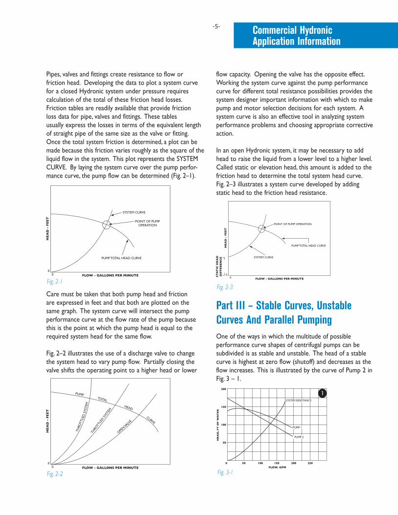
Pipes, valves and fittings create resistance to flow or friction head. Developing the data to plot a system curve for a closed Hydronic system under pressure requires calculation of the total of these friction head losses. Friction tables are readily available that provide friction loss data for pipe, valves and fittings. These tables usually express the losses in terms of the equivalent length of straight pipe of the same size as the valve or fitting. Once the total system friction is determined, a plot can be made because this friction varies roughly as the square of the liquid flow in the system. This plot represents the SYSTEM CURVE. By laying the system curve over the pump perfor-mance curve, the pump flow can be determined (Fig. 2–1).
Care must be taken that both pump head and friction are expressed in feet and that both are plotted on the same graph. The system curve will intersect the pump performance curve at the flow rate of the pump because this is the point at which the pump head is equal to the required system head for the same flow.
Fig. 2–2 illustrates the use of a discharge valve to change the system head to vary pump flow. Partially closing the valve shifts the operating point to a higher head or lower
flow capacity. Opening the valve has the opposite effect. Working the system curve against the pump performance curve for different total resistance possibilities provides the system designer important information with which to make pump and motor selection decisions for each system. A system curve is also an effective tool in analyzing system performance problems and choosing appropriate corrective action.
In an open Hydronic system, it may be necessary to add head to raise the liquid from a lower level to a higher level. Called static or elevation head, this amount is added to the friction head to determine the total system head curve. Fig. 2–3 illustrates a system curve developed by adding static head to the friction head resistance.
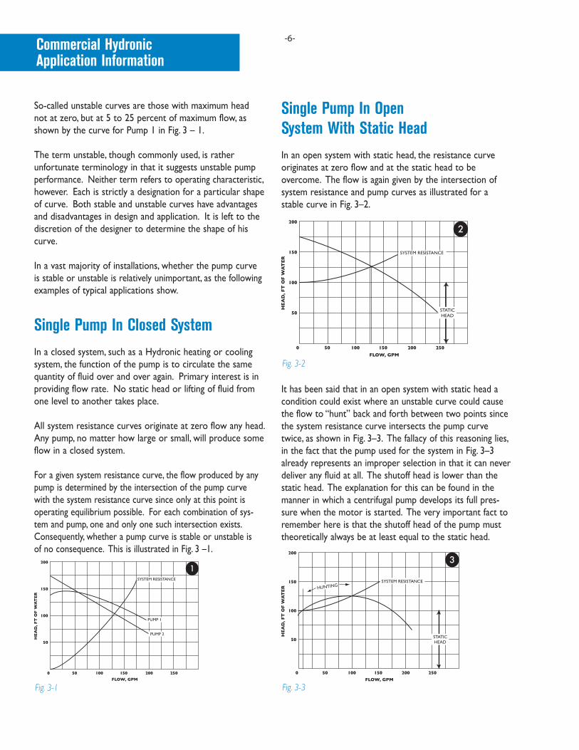
Part III – Stable Curves, Unstable Curves And Parallel PumpingOne of the ways in which the multitude of possible performance curve shapes of centrifugal pumps can be subdivided is as stable and unstable. The head of a stable curve is highest at zero flow (shutoff) and decreases as the flow increases. This is illustrated by the curve of Pump 2 in Fig. 3 – 1.
Commercial Hydronic Application Information
1Fig. 2-1
2Fig. 2-2
Fig. 2-3
Fig. 3-1
-6-
So-called unstable curves are those with maximum head not at zero, but at 5 to 25 percent of maximum flow, as shown by the curve for Pump 1 in Fig. 3 – 1.
The term unstable, though commonly used, is rather unfortunate terminology in that it suggests unstable pump performance. Neither term refers to operating characteristic, however. Each is strictly a designation for a particular shape of curve. Both stable and unstable curves have advantages and disadvantages in design and application. It is left to the discretion of the designer to determine the shape of his curve.
In a vast majority of installations, whether the pump curve is stable or unstable is relatively unimportant, as the following examples of typical applications show.
Single Pump In Closed SystemIn a closed system, such as a Hydronic heating or cooling system, the function of the pump is to circulate the same quantity of fluid over and over again. Primary interest is in providing flow rate. No static head or lifting of fluid from one level to another takes place.
All system resistance curves originate at zero flow any head. Any pump, no matter how large or small, will produce some flow in a closed system.
For a given system resistance curve, the flow produced by any pump is determined by the intersection of the pump curve with the system resistance curve since only at this point is operating equilibrium possible. For each combination of sys-tem and pump, one and only one such intersection exists. Consequently, whether a pump curve is stable or unstable is of no consequence. This is illustrated in Fig. 3 –1.
Single Pump In Open System With Static HeadIn an open system with static head, the resistance curve originates at zero flow and at the static head to be overcome. The flow is again given by the intersection of system resistance and pump curves as illustrated for a stable curve in Fig. 3–2.
It has been said that in an open system with static head a condition could exist where an unstable curve could cause the flow to “hunt” back and forth between two points since the system resistance curve intersects the pump curve twice, as shown in Fig. 3–3. The fallacy of this reasoning lies, in the fact that the pump used for the system in Fig. 3–3 already represents an improper selection in that it can never deliver any fluid at all. The shutoff head is lower than the static head. The explanation for this can be found in the manner in which a centrifugal pump develops its full pres-sure when the motor is started. The very important fact to remember here is that the shutoff head of the pump must theoretically always be at least equal to the static head.
Fig. 3-1
2
2
3Fig. 3-2
3
3
3Fig. 3-3
Commercial Hydronic Application Information
-7-
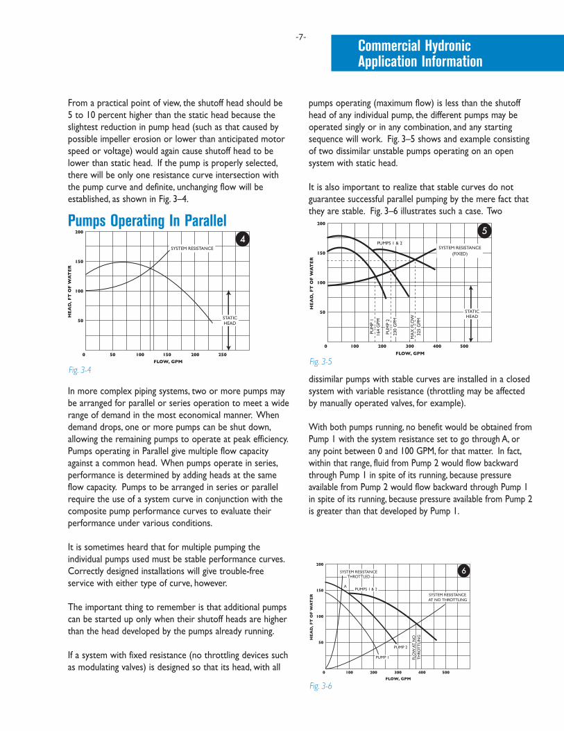
From a practical point of view, the shutoff head should be 5 to 10 percent higher than the static head because the slightest reduction in pump head (such as that caused by possible impeller erosion or lower than anticipated motor speed or voltage) would again cause shutoff head to be lower than static head. If the pump is properly selected, there will be only one resistance curve intersection with the pump curve and definite, unchanging flow will be established, as shown in Fig. 3–4.
Pumps Operating In Parallel
In more complex piping systems, two or more pumps may be arranged for parallel or series operation to meet a wide range of demand in the most economical manner. When demand drops, one or more pumps can be shut down, allowing the remaining pumps to operate at peak efficiency. Pumps operating in Parallel give multiple flow capacity against a common head. When pumps operate in series, performance is determined by adding heads at the same flow capacity. Pumps to be arranged in series or parallel require the use of a system curve in conjunction with the composite pump performance curves to evaluate theirperformance under various conditions.
It is sometimes heard that for multiple pumping the individual pumps used must be stable performance curves. Correctly designed installations will give trouble-free service with either type of curve, however.
The important thing to remember is that additional pumps can be started up only when their shutoff heads are higher than the head developed by the pumps already running.
If a system with fixed resistance (no throttling devices such as modulating valves) is designed so that its head, with all
pumps operating (maximum flow) is less than the shutoff head of any individual pump, the different pumps may be operated singly or in any combination, and any starting sequence will work. Fig. 3–5 shows and example consisting of two dissimilar unstable pumps operating on an open system with static head.
It is also important to realize that stable curves do not guarantee successful parallel pumping by the mere fact that they are stable. Fig. 3–6 illustrates such a case. Two
dissimilar pumps with stable curves are installed in a closed system with variable resistance (throttling may be affected by manually operated valves, for example).
With both pumps running, no benefit would be obtained from Pump 1 with the system resistance set to go through A, or any point between 0 and 100 GPM, for that matter. In fact, within that range, fluid from Pump 2 would flow backward through Pump 1 in spite of its running, because pressure available from Pump 2 would flow backward through Pump 1 in spite of its running, because pressure available from Pump 2 is greater than that developed by Pump 1.
4
4
3Fig. 3-45
5
3Fig. 3-5
6
6
3Fig. 3-6
Commercial Hydronic Application Information

-8-
In other words, Pump 2 overpowers Pump 1. For this reason, with Pump 2 running alone, Pump 1 should not be started unless Pump 2 operates to the right of the point where the curve of Pump 2 and the curve of Pumps 1 and 2 diverge (100 GPM) in Fig.3–6.
Parallel pumping is often an excellent way to obtain optimum operating conditions and to save energy. To be successful, however, systems and operating conditions must be understood. This applies to both stable and unstable pump curves.
Part IV – NPSH And Pump CavitationThe net positive suction head (NPSH) is an expression of the minimum suction conditions required to prevent cavitation in a pump. NPSH can be thought of as the head corresponding to the difference between the actual abso-lute pressure at the inlet to the pump impeller and the fluid vapor pressure. An incorrect determination of NPSH can lead to reduced pump capacity and efficiency, severe operating problems and cavitation damage.
It is helpful to define separately two basic NPSH consider-ations; required NPSH (NPSHR) and available (NPSHA).
The required or minimum NPSH is dependent on the design of a particular pump and is determined by the manufacturer’s testing of each pump model. The pump manufacturer can plot this required NPSH for a given pump model on performance curve and this value, expressed as feet of the liquid handled, is the pressure required to force a given flow through the suction piping into the impeller eye of the pump. Required NPSH can also be defined as the amount of pressure in excess of the vapor pressure required by a particular pump model to prevent the formation of vapor pockets or cavitation. Required NPSH, then, varies from one pump manufacturer to the next and from one manufacturer’s model to another. The required NPSH for a particular pump model varies with capacity and rapidly increases in high capacities.
The available NPSH, on the other hand, is dependent on the piping system design as well as the actual location of the pump in that system. The NPSH available as a function of system piping design must always be greater than the NPSH required by the pump in that system. The NPSH available as a function of system piping design must always be greater
than the NPSH required by the pump in that system or noise and cavitation will result. The available NPSH can be altered to satisfy the NPSH required by the pump, if changes in the piping liquid supply level, etc., can be made. Increasing the available NPSH provides a safety margin against the potential for cavitation. The available NPSH is calculated by using the formula:
NPSHA = ha +/- hs - hvpa – hf where: ha = atmospheric pressure in feet absolutehs “+” = suction head or positive pressure in a closed system, expressed in feet gaugehs “-” = suction lift or negative pressure in a closed system, expressed in feet gaugehvpa = vapor pressure of the fluid in feet absolutehf = pipe friction in feet between pump suction and suction reference point.
Cavitation can be defined as the formation and subsequent collapse of vapor pockets in a liquid. Cavitation in a centrifugal pump begins to occur when the suction head is insufficient to maintain pressures above the vapor pressure. As the inlet pressure approaches the flash point, vapor pockets form bubbles on the underside of the impeller vane which collapse as they move into the high-pressure area along the outer edge of the impeller. Severe cavitation can cause pitting of the impeller surface and noise levels audible outside the pump.
The Taco pump performance curve below (Fig. 4–1) includes a plot of the required NPSH for a Taco Model 1506. If a pump capacity of 105 GPM is used as an example capacity requirement, reading vertically from that GPM rate shows a required NPSH of 4 feet. An available system NPSH greater than 4 feet would, therefore, be necessary to ensure satisfactory pump performance and operation.
Curve no. 2015Min. Imp. Dia. 4.25"Size 2 x 1.5 x 6
MS 2-18-02 PC-2015 RevB ECN10627
FEET
KPa
0
2 20
0
2
0 0
101
303
404
505
606
707
808
909
10010
11011
12012
4 6 8 101 3 5 7 9 11
2 6
4 12
6 18
8 24
(121mm)
REQUIRED NPSH
6.25"
5.75"
5.25"
4.75"
4.25"
CURVES BASED ON CLEAR WATERWITH SPECIFIC GRAVITY OF 1.0
1HP(.75KW)
.75HP.5HP
.33HP(.25KW)
1.5HP(1.1KW)
(159mm)
(146mm)
(133mm)
(108mm)
(.37KW)
(.56KW)
54%
57%42
%46
%
46%
42%
54%57%
60%
64.5
%
63%
63%
60%
HEA
D IN
FEE
T
0 25 50 75 100 125 150 175 2000
10
20
30
40
50
FLOW IN GALLONS PER MINUTE
Model 1506 1760 RPMAugust 9, 2001CI & FI Series
L/SEC
HEA
D IN
MET
ERS
HEA
D IN
KIL
OPA
SCA
LS
NPSH
Fig. 4-1
Commercial Hydronic Application Information
-9-
FLOW IN LITERS PER SECOND
HEA
D IN
FEE
T
HEA
D IN
MET
ERS
HEA
D IN
KIL
OPA
SCA
LS K
Pa
FLOW IN GALLONS PER MINUTE
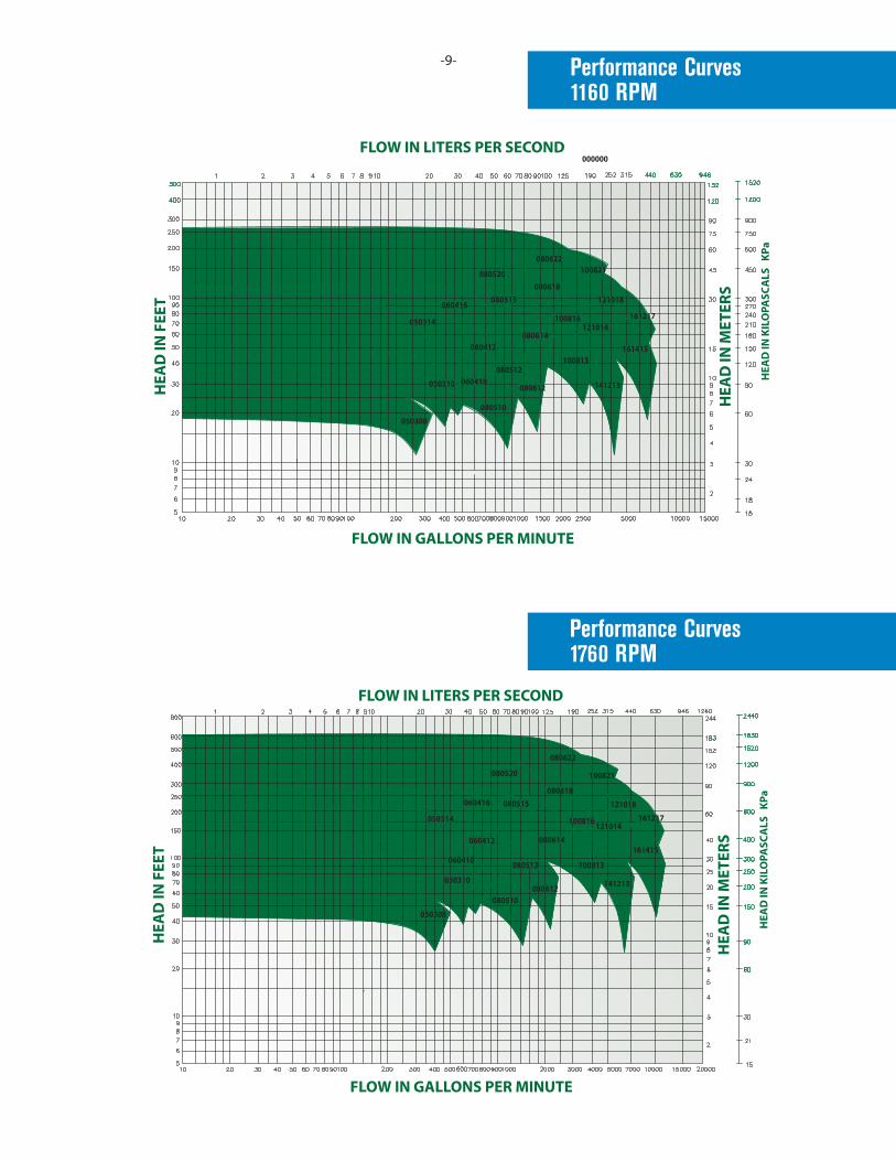
TC SERIES QUICK SELECTION 1760RPM
080622
141213
080614
100816
100813060410
050310
050308
080510080612
080512
080515060416
050314
060412
121014
161415
161217
080618
121018
100821080520
000000
080520
080622100821
080618080515060416
050314
060412
050310 060410
050308
080510
080612
080512
080614
100813
141213
161415
161217121014
121018
100816
FLOW IN LITERS PER SECONDH
EAD
IN F
EET
HEA
D IN
MET
ERS
HEA
D IN
KIL
OPA
SCA
LS K
Pa
FLOW IN GALLONS PER MINUTE
TC SERIES QUICK SELECTION 1160RPM
Performance Curves1760 RPM
Performance Curves1160 RPM
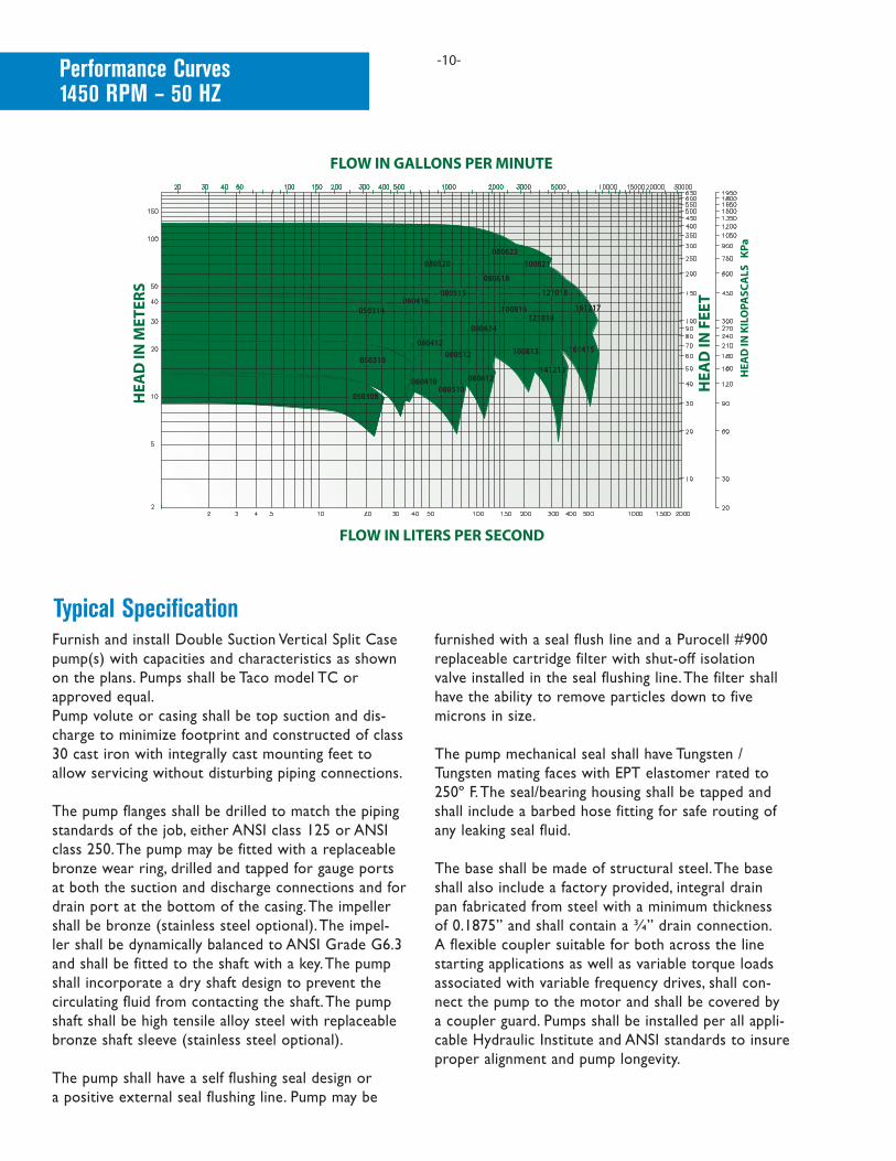
-10-Performance Curves1450 RPM – 50 HZ
FLOW IN GALLONS PER MINUTEH
EAD
IN M
ETER
S
HEA
D IN
FEE
T
HEA
D IN
KIL
OPA
SCA
LS K
Pa
FLOW IN LITERS PER SECOND
TC SERIES QUICK SELECTION 1450 RPM
080622100821
121018
161217
161415
141213
100813
121014100816
080618
080520
080515060416
050314
080614
060412080512
080612080510
060410
050310
050308
Furnish and install Double Suction Vertical Split Case pump(s) with capacities and characteristics as shown on the plans. Pumps shall be Taco model TC or approved equal.Pump volute or casing shall be top suction and dis-charge to minimize footprint and constructed of class 30 cast iron with integrally cast mounting feet to allow servicing without disturbing piping connections.
The pump flanges shall be drilled to match the piping standards of the job, either ANSI class 125 or ANSI class 250. The pump may be fitted with a replaceable bronze wear ring, drilled and tapped for gauge ports at both the suction and discharge connections and for drain port at the bottom of the casing. The impeller shall be bronze (stainless steel optional). The impel-ler shall be dynamically balanced to ANSI Grade G6.3 and shall be fitted to the shaft with a key. The pump shall incorporate a dry shaft design to prevent the circulating fluid from contacting the shaft. The pump shaft shall be high tensile alloy steel with replaceable bronze shaft sleeve (stainless steel optional).
The pump shall have a self flushing seal design or a positive external seal flushing line. Pump may be
furnished with a seal flush line and a Purocell #900 replaceable cartridge filter with shut-off isolation valve installed in the seal flushing line. The filter shall have the ability to remove particles down to five microns in size.
The pump mechanical seal shall have Tungsten / Tungsten mating faces with EPT elastomer rated to 250º F. The seal/bearing housing shall be tapped and shall include a barbed hose fitting for safe routing of any leaking seal fluid.
The base shall be made of structural steel. The base shall also include a factory provided, integral drain pan fabricated from steel with a minimum thickness of 0.1875” and shall contain a ¾” drain connection. A flexible coupler suitable for both across the line starting applications as well as variable torque loads associated with variable frequency drives, shall con-nect the pump to the motor and shall be covered by a coupler guard. Pumps shall be installed per all appli-cable Hydraulic Institute and ANSI standards to insure proper alignment and pump longevity.
Typical Specification
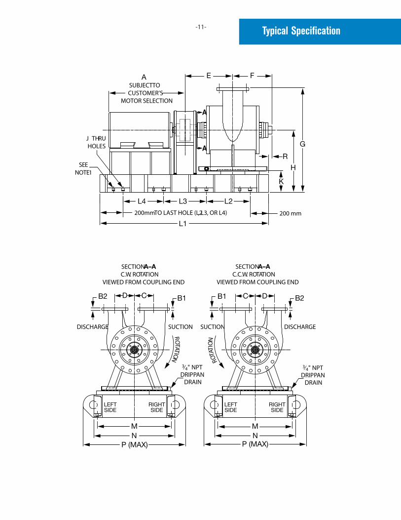
-11- Typical Specification
SUBJECT TOCUSTOMER’S
MOTOR SELECTION
A
A
J THRUHOLES
200 mm200mm TO LAST HOLE (L2, L3, OR L4)
SEENOTE 1
SECTION A–AC.C.W. ROTATION
VIEWED FROM COUPLING END
SUCTIONDISCHARGE
ROTATION
ROT
ATIO
N
3⁄4 NPTDRIP PAN
DRAIN
3⁄4 NPTDRIP PAN
DRAIN
SUCTION DISCHARGE
SECTION A–AC.W. ROTATION
VIEWED FROM COUPLING END

-12-TC Series Pump Dimensions
Model No.
Flange Size
HP1760RPM
MotorFrame
A*
B1 Suction B2 Discharge
C D E F G H J K L1 L2 L3 L4 M N P RANSICLASS
125
ANSICLASS
250
ANSICLASS
125
ANSICLASS
250
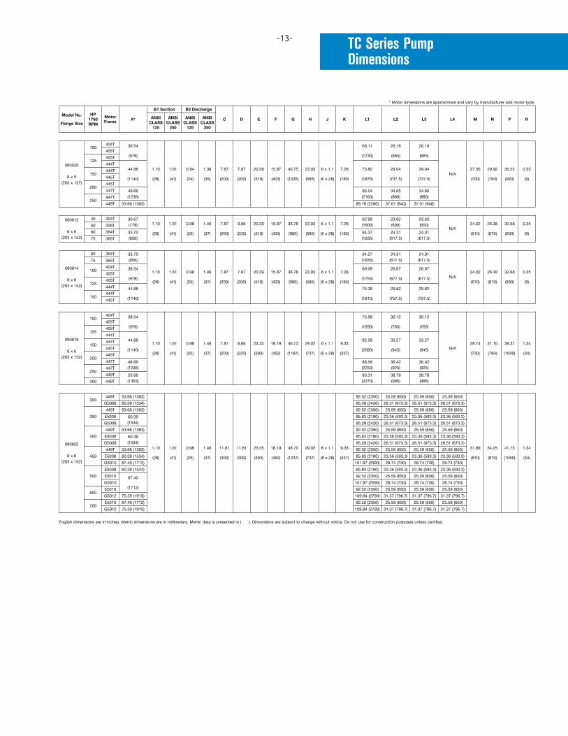
TC Series Pump Dimensions
-13-
Model No.
Flange Size
HP1760RPM
MotorFrame
A*
B1 Suction B2 Discharge
C D E F G H J K L1 L2 L3 L4 M N P RANSICLASS
125
ANSICLASS
250
ANSICLASS
125
ANSICLASS
250
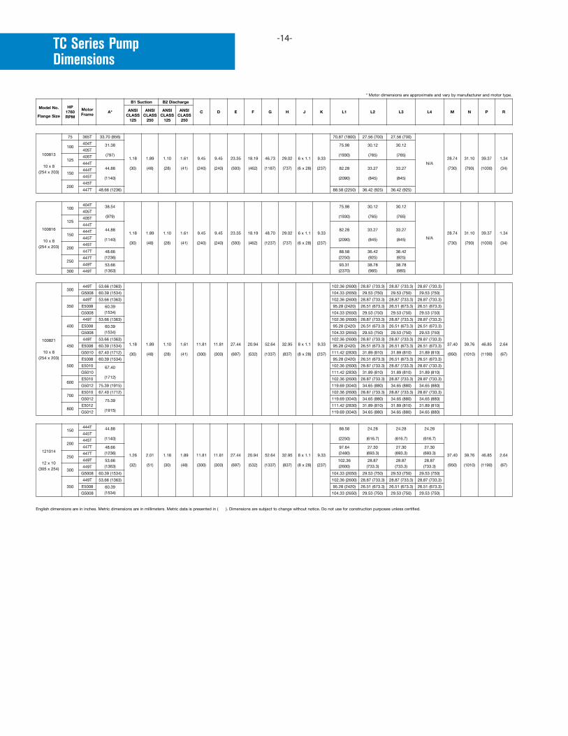
TC Series Pump Dimensions
-14-
Model No.
Flange Size
HP1760RPM
MotorFrame
A*
B1 Suction B2 Discharge
C D E F G H J K L1 L2 L3 L4 M N P RANSICLASS
125
ANSICLASS
250
ANSICLASS
125
ANSICLASS
250
TC Series Pump Dimensions
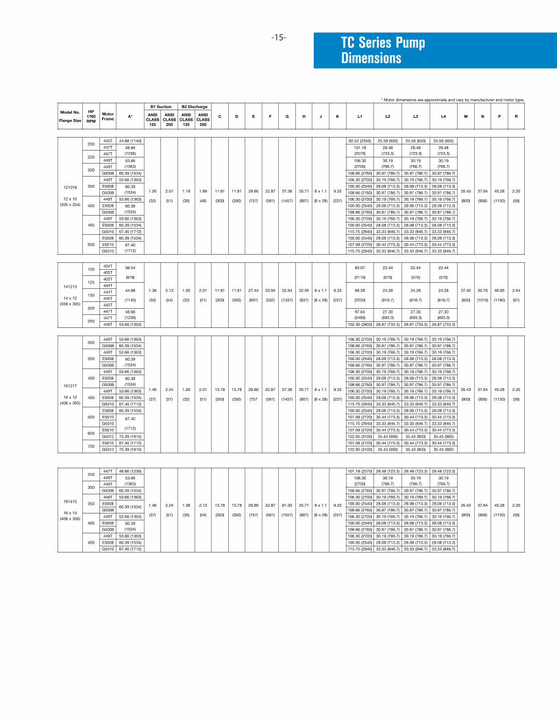
-15-
Model No.
Flange Size
HP1760RPM
MotorFrame
A*
B1 Suction B2 Discharge
C D E F G H J K L1 L2 L3 L4 M N P RANSICLASS
125
ANSICLASS
250
ANSICLASS
125
ANSICLASS
250
Model No.
Flange Size
HP1760RPM
MotorFrame
A*
B1 Suction B2 Discharge
C D E F G H J K L1 L2 L3 L4 M N P RANSICLASS
125
ANSICLASS
250
ANSICLASS
125
ANSICLASS
250

Taco Inc., 1160 Cranston Street, Cranston, RI 02920 / (401) 942-8000 / Fax (401) 942-2360 Taco (Canada) Ltd., 8450 Lawson Road, Unit #3, Milton, Ontario L9T 0J8 / (905) 564-9422 / Fax (905) 564-9436
www.taco-hvac.com