Embed Size (px)
Citation preview

TBUPS 800
The requirement for power supply reliability is growing, due to the increasing application of information and data carrier systems, text processing, automated production processes and complex data networks.Irregularities due to loading of the public power supply by major users, peak-time use or by lightning strikes cannot be avoided.The result is:Mains voltage breaks, spikes and transients. Static UPS’s are being installed increasingly for loads that require AC voltages unaffected by interference on the mains e.g.• Data processing installations• Process control computers• Air safety installations• Signalling, alarm systems• Telecommunication systems• Power- and Substations
DESIGN
RECTIFIERThe rectifier consists of an IGBT bridge with power factor correction (power factor = 1), converting the three phase mains voltage via an autotrans-former (optional isolated transformer) into a controlled DC voltage to supply the inverter and to recharge the connected battery or to keep the battery in optimum capacity in float charge condition.The rectifier is able to supply the fully loaded inver-ter and to recharge the discharged 12 hours.The restart of parallel systems is done in steps so that not all UPS’s are starting at the same time.The rectifier is also equipped with an IU charging characteristic in accordance with the information of the battery anufacturer,with the option of battery temperature compen-sation.
INVERTERThe inverter power block changes DC voltage into a single or three phase sinusoidal AC voltage with constant amplitude and stable frequency. The output voltage is independent of line disturbances or power failures.The unit works with an IGBT inverter bridge with pulse width modulation having a high efficiency in the partial load range as well as achieving a low distortion factor at non linear load.In the event of mains interruption or failure, the battery connected to the DC input is brought in automatically and with - out interruption to supply current. If the battery becomes discharged this is reported. If the battery discharge limit is excee-ded, the inverter automatically turns off and a warning is given shortly before the discharged voltage limit is reached.Automatic change-over of the load to the bypass mains or a suitable spare supply occurs if the supply from the inverter falls outside the preset tolerances.
Due to the use of IGBT transistors of the newest technology in the rectifier and in the inverter, the new TBUPS 800 range fulfills the highest reliabilty for power supplies and is very economical.This results in an input power factor of ≥ 0,99 and an input distortion factor of < 5 %. The exceptional characteristics of this inverter in the TBUPS 800 series results in very small dynamic voltage deviations even in the case of one hundred percent load changes.
UpdatedFifty years of experience
UnbeatableRobust and flexible technology
Designed for industrial environments
Performance and reliability
Standard configurationPower and control
TBUPS 800
INTERNAL MANUAL BYPASS
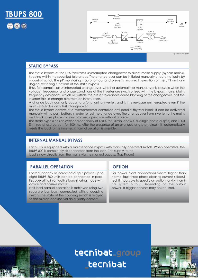
PARALLEL OPERATIONFor redundancy or increased output power, up to eight TBUPS 800 units can be connected in para-llel, operating in an active load-sharing mode with active and passive master.Half load parallel operation is achieved using two separate bus bars, connected with a coupling switch. The state of the coupling switch is relayed to the microprocessor, via an auxiliary contact.
OPTIONFor power plant applications where higher than normal fault three phase clearing current is Requi-red, it is possible to specify an option for 4 x I nomi-nal system output. Depending on the output power, a bigger cabinet may be required.
Each UPS is equipped with a maintenance bypass with manually operated switch. When operated, the TBUPS 800 is completely disconnected from the load. The supply to the load is now directly from the mains via the manual bypass. (Top Figure)
STATIC BYPASSThe static bypass of the UPS facilitates uninterrupted changeover to direct mains supply (bypass mains), keeping within the specified tolerances. The change-over can be initiated manually or automatically by a control signal. The μP monitoring is autonomous and prevents incorrect operation of the UPS and any illogical switching functions of the static bypass.Thus, for example, an uninterrupted change-over, whether automatic or manual, is only possible when the voltage, frequency and phase conditions of the inverter are synchronised with the bypass mains. Mains frequency deviations, which lie outside the preset tolerances cause blocking of the changeover, or if the inverter fails, a change-over with an interruption.A change back can only occur to a functioning inverter, and is in everycase uninterrupted even if the mains should fail on a test change-over.The static bypass consists of a microprocessor-controlled anti parallel thyristor block. It can be activated manually with a push button, in order to test the change-over. The changeover from inverter to the mains and back takes place in a synchronised operation without a break.The static bypass has an overload capability of 150 % for 10 min. and 500 % (single phase output) and 1000 % (three phase output) for 100 ms. After the presence of an overload or a short-circuit, it automatically resets the load to the inverter, if normal peration is possible.

TBUPS 800
FRONT PANELThe operation of the UPS is made by a plastic foil key board with 6 keys, 4 three coloured and 2 single coloured LED’s. There is a mimic diagram on the operating section. The operating condition and any operational disturbances are represented by the multi colour LED’s. There is a 4-line, 80-digit LC display in the operating section for reading information and/or for clear guidance by the menu. Control of the operating section takes place via the display controller, which communicates over the CAN bus with the controller board. In addition, the most important operating and fault signals are indicated by 13 single LED’s. (Top figure)
RECTIFIER• Input voltage (each phase/phase or phase/neutral conductor)•Input current of each phase•Frequency
INVERTER•Output voltage (with three phase output phase/phase or phase/neutral conductor)•Frequency•Output current (with three phase output of each phase)•Aparent power•Real power
BATTERY•Voltage•Charge/Discharge current•Remaining back up time•Remaining capacity
BYPASS•Input voltage (with three phas eoutput phase/phase or phase/neutral conductor)•Input current (with three phase output of each phase)•Frequency
An event recorder stores each occurring event (push button operation, switching events and error) with date time. Up to 1200 entries an be stored.
The following information is indicated via 6 volt free change over contacts:•mains operation (mains OK) •battery operation •bypass operation
As serial interfaces a RS232 and RS485 each with MODBus protocol is provided as standard, additionally an analogue output with 0 or 4 to 20 mA is included which can be programmed with an internal value, e.g. output power.
Digital inputs:•EMERGENCY POWER OFF (EPO)•remote ON/OFF •inhibit battery charging •generator operation•inhibit bypass operation
As an option an additional relay card with 6 relays and an additional interface card with a RS232 and RS485 can be build in, also a Profibus interface and network interface (TCP/IP) can be added.
Internal power supply
UPS mains operation
UPS battery operation
Bypass operation
Parallel operation
Manual bypass
Overload
Inverter failure
Mains failure
Battery voltage low
•manual bypass activated•low battery voltage•common alarm

TBUPS 800
UPSMAN/UPSMON – CS121 WEB/ ADAPTER UPS FUNCTIONS
PARALLEL HANDLINGA UPS system provides security for a critical appli-cation. Purchasing a parallel redundant system, provides even further security. Consequently it is necessary to consider parallel systems as a single unit. Critical measurements, such as battery auto-nomy are calculated and expressed for the com-bined system.A shutdown is not initiated until the parallel System is unable to deliver the load current demanded. Major system alarms are not activated unless the situation has reached a critical state. This functio-nality can be realised using different Power Mana-gement Solutions and Software Packages.
POWER MANAGEMENT SOLUTIONS• Environmental Monitoring• Integration in Network Management System• Integration in building Management System• ModBus interface• ProfiBus interface• Remote Monitoring System through WEB• Remote Monitoring System with SNMP• Redundant UPS Monitoring• Integration in Multivendor/ Multiplatform environments• Extensive alarm handling/ Dispatching
UPS-Managenemt software for Windows
95/98/2000/NT/XP®
Envorimental monitorning-Facility management e.g.
BENNING Sitemanager,Siteminitor, Tempman,
Siteswitch
UPS-Managenemt software for
Novell NetWare®
_
UPS-Managenemt software for
Unix®/Mac Os® Systems
_
CS121 – SNMPWeb-Mager®
Envoronmental monitorning-Facility management e.g.
BENNING Sitemanager, Sitemonitor, Tempman,
Siteswitch
UPS – Standard functions/warninge.g. battery low/power failure/overload/UPS connection restored/System shutdown
UPS – Extended functions/warningse.g. Inverter overload/Fuse blown/Rectifier mains fault/Inverter feeding/Battery switch open
UPS – send UPS shutdown signalUPS – SNMP redundancy capability (USW software)
Graphic display UPSMON/HTML/JAVA

TBUPS 800
TECHNICAL DATATBUPS 800 3-3 with three phase input and three phase output - DIN Type: D400 D400/...../2 rfg-UDG....Nominal power cos. 0,8: [kVA] 60, 80, 100, 120Type TBUPS 800UPS Nominal output power (cos =0,8 ind.):
Type TBUPS 800Max. input power:Nominal input power without battery chargingNominal input current without battery charging (at 400V)Max. input current with high rate charging (at 400V)TransformerInput power factorNominal input voltageNominal input frequencyMains distortion (at 100% load)Current ripple
Battery dataRecommended number of battery cellsMax. charging current
Inverter data TBUPS 800 3-3Inverter input voltageNominal input real power(with load cos. =0,8 ind.):Nominal output real power (cos. =1):Nominal output current (cos. = 0,8):Nominal output cuurent (cos. =1):Nominal output voltage:Nominal output frequency:Transformer:Voltage tolerance: -static -50% asymmetric load -100% asymmetric load -dynamic with 100% loar chargeRelation time:Angle deviation: -symmetric load -50% asymmetric load -100% asymmetric loadFrequency tolerance: -mains synchronised -self synchronisedDistortion factor (acc. EN 62040-1): -linear load -non linear loadCrest factor:Overload: -3ph -1ph / NShort-circuit behaviour: -3ph -1ph / N
Inverter efficiency(with nominal load cos. =0,8):
80
8875
109127
autotransformer (optional galvanically isolated)≥0,99 (0,97 already at 25% load)
3/N 400 V ± 15% 50 Hz ± 5%
≤ 5< 5 A / 100 Ah
180 - 20434
317 - 470
65,5
6411692
3/N 400V (adjustable ±5%)50
galvanically isolated
± 1± 1± 3< 5
< 10
< 1º< 2º< 3º
± 1 (synchronisation ± 4)± 0,1
< 1< 5≥ 3
150% 60 sec., 125% 10 min.220% 60 sec., 180% 10 min.
200 % 3 sec.350% 3 sec.
Inverter itself is short circuit proof, switch OFF after max. 3 seconds if bypass mains is not available (EN 62040)
≥94
[kVA][kVA][A][A]
[cos. ][V][Hz][%]
[A]
[V]
[kW]
[kW][A][A][V][Hz]
[%][%][%][%]
[msec]
[%][%]
[%][%]
[%][%]
[%]
[%]
[kWA] 60
66588496
26
49
488770
120
129108156186
52
98
96173139

GENERAL DATA
TBUPS 800
Type TBUPS 800UPS Nominal output power (cos =0,8 ind.):
General dataOver all efficiency (AC to AC) without battery charging -100% load -75% load -50% load -25% loadHeat dissipation 100% load 0% loadNoise level with 1 m distancePermitted ambient tempRelative humidityPermited installation heightHumidity classProtection degreeRadio interferenceDimensions Widht Depth HeightWeight
Cable entryPainting
Static Bypass Nominal voltageNominal frequencyOver load -10 min. -100 msec.Transfer limitsInverter/Bypass transfer time -Inverter failure -Overload or manual transfer
Byypass/inverter transfer timeOther oprions
80
929291895,92,3
0 to + 40 (daily average ≤ 35)5 - 95 without condensing
< 1000 m above sea level without deratingDIN/IEC 721 2-1-09/86
IP 20 (DIN/VDE 0470 part 11/92 IEC 529) / others optional
EN 50091-2 standard class A (optional class B)
800800
2000 (optional 2200 height)900
from bottom (optional from top with cable cabinet, widht 200mm)RAL 7035, structured power coating
400 / 23050
1501000
U±10; F±5
< 1< 1
Interlock when transfer was activated 5 times within a minute< 1
e.g. bypass transformer on request
[kW][kW]
[db(A)][ºC][%][m]
[mm][mm][mm][kg]
[V][Hz]
[%][%][%]
[msec][msec]
[msec]
[kWA]
Cooling: forced cooled with speed controlled, redundant and monitored fans, build in the air inlet, equipped with air flaps, which close in case of fan failure, fans can be changed from front, power blocks and transformers are temperature monitored, prewarning will be sent out, after temperature increase switch OFF, air inlet from front, air outlet from top
60
929291894,72,3
900
120
929291898,33,2≤ 65
1100
≤65