Embed Size (px)
Citation preview
INSTALLATION INSTRUCTIONS for TTi Hemi Header Part No’s:
TTIHEMI625-218 / TTIHEMI625-214
TAKE TIME TO READ THE INSTALLATION PROCEDURES BEFORE STARTING
Please take all under car safety precautions when installing headers, including eye protection. When raising vehicle, use an appropriate lifting devise and place on jack stands as a safety measure. Caution! Bumper jacks are intended for emergency use only and should not be used to support vehicle.
First check your Engine Location TTI's headers were designed to fit with the engines located to the factory specifications. If the engine is not located correctly in the chassis, the headers will not fit properly. Use the following dimensions to check your engine location before installing your headers. From the center of the crankshaft to the top of the K-frame the correct distance is 5-1/4”. The engine is also offset toward the passenger-side. Measure from the center of the crankshaft to each frame rail. The difference should be 3”. If necessary place shims between the insulator assembly and the K-frame mounting pad to achieve the proper dimensions. With the engine mounted in the correct location the headers will fit properly. 1. Disconnect the negative cable from the battery terminal.
2. Raise the front of the vehicle with an appropriate lifting device and place on jack stands.
3. Remove the stock exhaust pipes. If you are installing the complete TTI Exhaust System, then remove and discard your entire stock exhaust system, including hangers.
4. Drivers-side: Remove the starter, the left-side exhaust manifold and the oil dipstick tube. Note: The oil dipstick tube will require re-bending. See the modified Hemi Dipstick illustration - Sheet #502. • If equipped with Power Steering, remove the left-side motor mount nut and raise the engine approximately 1½”. Use a
block of wood between the oil pan and the floor jack. You can now remove the stock cast iron manifold. If equipped with the 3pc kick-down linkage, remove the pivot shaft from the transmission case to allow the header to slip into place with less difficulty.
• On models with Automatic Transmission and Floor Shift, re-position the adjustable swivel and the lower rod attached to the torque shaft lever. Move them to the upper side of the torque shaft lever to clear the header collector. See the modified Torque Shaft Lever illustration - Sheet #3703.
5. Now is a good time to check the condition of your engine mounts. If they are worn or deteriorated, replace them now. When the engine is mounted correctly the headers will fit correctly.
6. Drivers-side Header: Turn the steering wheel to the full right stop. • Check the cylinder head sealing surface of the exhaust ports to insure that they are clean. Insert the header into position
simultaneously with the starter from under the car. Before bolting to the cylinder head, place the starter motor into position and tighten the fasteners. Lower the engine back down onto the K-frame and reinstall the engine mount fastener. Use the original studs and nuts or the provided headers bolts to secure the header to the cylinder head. Place the supplied header gasket into position and start all of the fasteners. Tighten the center fasteners first then the end ports. Torque the bolts to 35 lbs. evenly to insure a proper seal.
• Re-connect the wiring to the starter. Adjust the wiring to insure that there is absolutely no contact with the header. A minimum of 3/8” clearance is required between the header and wiring.
Page 1 of 5
WARNING !!! We strongly suggest that you use an old set of headers or a set of cast iron manifolds for first engine runs / cam break-ins to avoid coating damage. Excessive heat damage to the ceramic coating will VOID all warranties. Header coating damage usually occurs during the first engine run when the exhaust temperatures exceed 1200°F. Excess exhaust temperatures are normally caused by excessively lean or excessively rich air/fuel mixtures and/or incorrect ignition timing.
• Reinstall the pivot shaft to the transmission case and connect the kick-down linkage. • Reinstall the modified oil dipstick tube.
7. Passenger-side: Remove the right-side motor mount nuts and raise the engine approximately ½”. Use a block of wood between the oil pan and the floor jack. You can now remove the stock cast iron manifold. • Note: Since there are no provisions on the header for the Hot Air Tubes to the intake manifold, the hot air tubes to the
intake manifold can be removed. • After removing the casts iron manifold, lower the engine back onto the mount and replace the nuts. • On models with a 4-Speed Standard Transmission, it may be necessary to trim a casting ear from the bell housing that
will interfere with the #4 header tube. This must be done prior to the header installation.
8. Passenger-side Header: Check the sealing surface of the exhaust ports to insure they are clean and free of any foreign material. Turn the steering wheel to the full left position. • Insert the header into position from under the car. • Place the supplied header gasket into position and start all of the header bolts. • Tighten the center fasteners first then the end ports. Torque the bolts to 35 lbs. evenly to insure a proper seal. • Automatic Transmission Only Attach fluid level tube bracket to the rear lower header flange bolt and the fluid level
tube with the supplied hardware.
9. Attach the adapter / reducers to the header collectors with the nuts, bolts and gaskets provided. The adapter / reducers are marked Left & Right and may need to be shortened for your application.
10. Re-connect the negative battery cable.
11. Now that your headers are installed, wipe down the tubes with hot soapy water or an environmentally safe Orange Cleaner Degreaser and a soft cloth to remove any grease or skin oils (finger prints) from the header tube surface. Never use abrasive cleaners. • It is normal for Chrome plated headers to discolor almost immediately after firing-up engine. • To insure years of service from your ceramic-coated headers it is suggested to follow our Header Maintenance & Care
procedures.
12. Start the engine and check for leaks.
Re-torque all of the header bolts after approximately 50 miles of driving To complete the rest of your exhaust system installation, we highly recommend the use of our TTI Performance Exhaust Systems. The 2-1/2” or 3” O.D. kits will bolt directly to the TTI Headers. Our exhaust systems come complete with all hardware and all new hanger assemblies. They are manufactured with aluminized tubing and are mandrel bent by the latest technology CNC tube benders insuring precision fit on every installation.
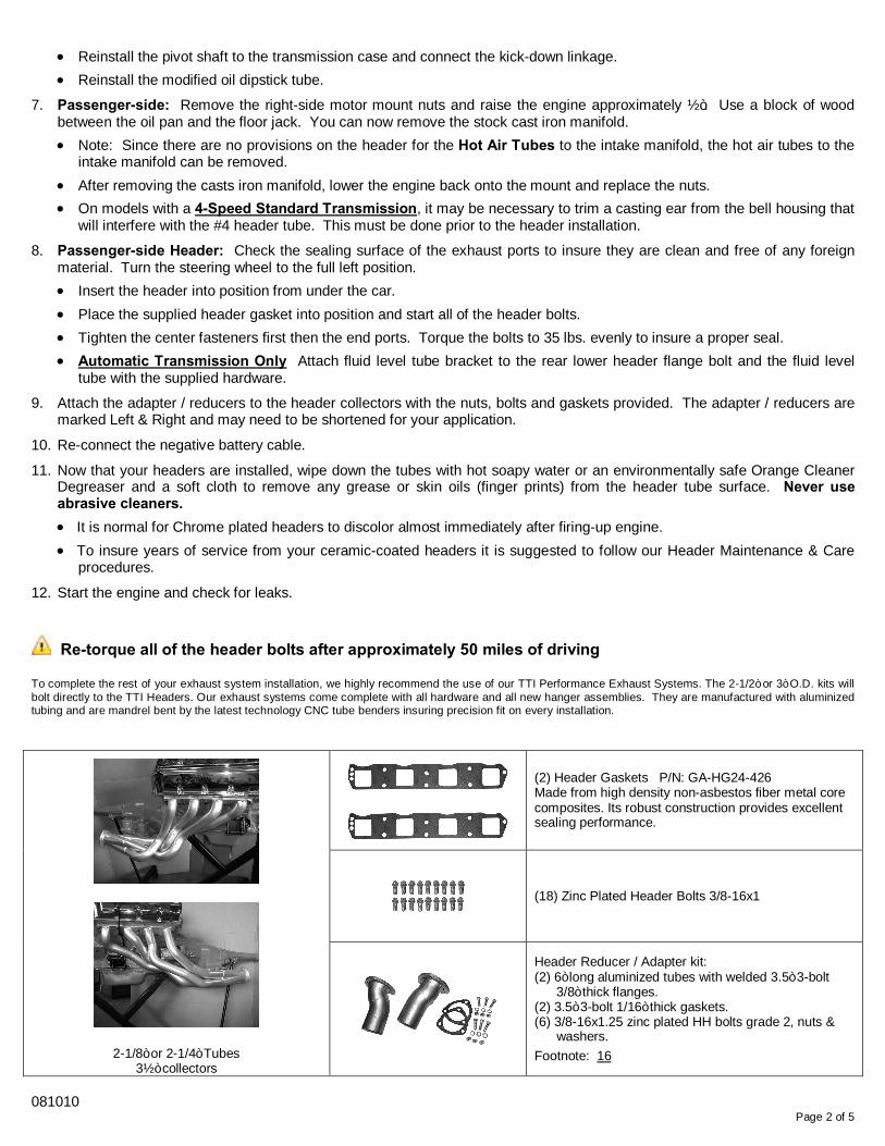
2-1/8” or 2-1/4” Tubes 3½” collectors
(2) Header Gaskets P/N: GA-HG24-426 Made from high density non-asbestos fiber metal core composites. Its robust construction provides excellent sealing performance.
(18) Zinc Plated Header Bolts 3/8-16x1
Header Reducer / Adapter kit: (2) 6” long aluminized tubes with welded 3.5” 3-bolt 3/8” thick flanges. (2) 3.5” 3-bolt 1/16” thick gaskets. (6) 3/8-16x1.25 zinc plated HH bolts grade 2, nuts & washers. Footnote: 16
081010
Page 2 of 5
INSTALLATION INSTRUCTIONS for TTi Hemi Header Part No’s:
TTIHEMI625-218 / TTIHEMI625-214 1962-1965 “B”-body Footnotes
Front Ends Stock 33
Engine Sizes 426 / 472 / 528 crate engines 19, 37, 42
Cylinder Heads OEM / Stage 5 (Low-Port) / Edelbrock (Standard Mopar Hd.) 14
Auto Trans Yes 23
Standard Trans Yes 53
Floor Shift Yes 23
Column Shift Yes 41
Push Button Yes
Power Steering Yes
Manual Steering Yes
Air Conditioning Yes
Starters Listed mini starters only 10
Flywheel / Bellhousing 10.5” or 11” 28
Steering Linkage OEM only 12, 33
Clutch Linkage OEM only 22
Oil Filters OEM
Oil Pans OEM or Milodon 11
Valve Covers OEM or Cast Aluminum
Footnotes
10 Starters required / 10.5" (130-tooth ring gear): Chrysler Lightweight Mini Starters - part #'s: R53005984, 56027702AC Mopar Performance Lightweight Mini Starters - part #'s: P5249644AB, P5007860, P4286522 / PowerMaster Adjustable Starter - part # 9523 Exception: Using an 11" flywheel (143-tooth ring gear) a RobbMc Performance starter #2005 is required.
11 Headers will clear OEM Oip Pans or Milodon part #'s: 31010, 30930, 30931 (7" - 7-3/4" sump depth)
12 Pitman Arm and Idler Arm: Headers will not clear the "Fast-Ratio" pitman and idler arms, which are 3/4" longer than stock arms. (Stock idler arm measures 5-1/4" from center to center)
14 If your cylinder head is not listed, TTI will not guarantee fit due to clearance issues, ie; Deck height, port locations or bolt pattern.
19 TTI does not make any headers for the Early 392 Hemi blocks.
22 Some Z-bars may require modification to clear header.
23 Torque Shaft Lever: Applications with an Auto Transmission & Floor Shifter will require the adjustable swivel and the lower rod attached to the torque shaft lever to be re-positioned to clear the header collector. Do-it-yourself modification Instruction sheet: #3703
28 Lakewood Bell-housing / Scattershield: Modification required to the passenger-side bell-housing. A half moon shaped notch will need to be ground down approximately 1/4” deep to clear the header tube.
33 Unisteer Rack & Pinion: Headers will not clear the Unisteer Rack & Pinion.
37 Headers fit with Schumacher engine mounts or equivalent.
41 To achieve column shift clearance, modification will be required to the shift linkage.
42 Hemi blocks with 440 RB mount ears will require modification to the casting on the driver-side. Approximately 3/8” of the material must be removed to clear the header tube and a fabricated steel mount will be required.
53 Transmission: Headers will fit with the Tremec TKO-500 / TKO-600 5-speed by Keisler. It is imperative that the output end of the tail shaft is in exactly the same position as the "stock" transmission output shaft for the headers to fit properly.
081010
Page 3 of 5
Sheet # 502
Hemi Dipstick
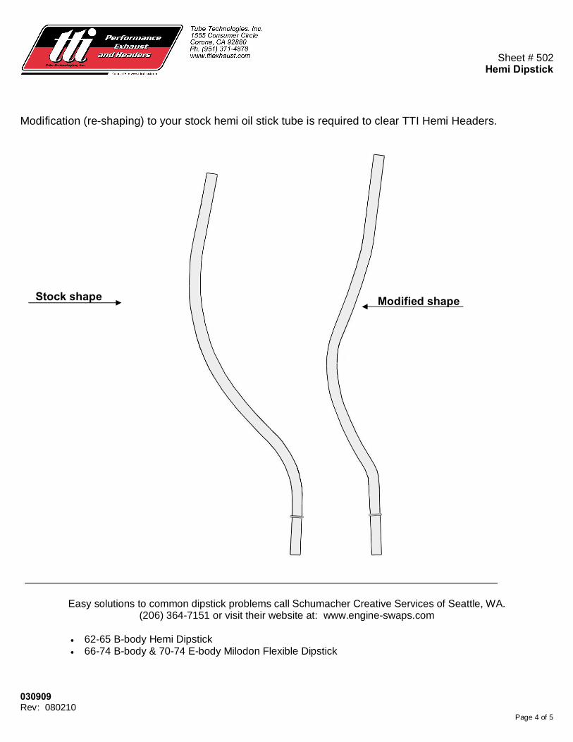
Modification (re-shaping) to your stock hemi oil stick tube is required to clear TTI Hemi Headers.
Easy solutions to common dipstick problems call Schumacher Creative Services of Seattle, WA. (206) 364-7151 or visit their website at: www.engine-swaps.com
• 62-65 B-body Hemi Dipstick • 66-74 B-body & 70-74 E-body Milodon Flexible Dipstick
030909 Rev: 080210
Page 4 of 5
Stock shape Modified shape
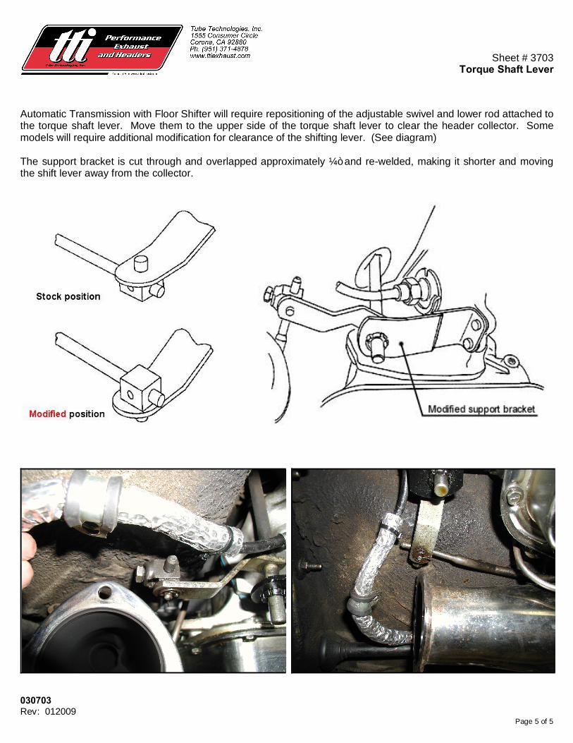
Sheet # 3703
Torque Shaft Lever
Automatic Transmission with Floor Shifter will require repositioning of the adjustable swivel and lower rod attached to the torque shaft lever. Move them to the upper side of the torque shaft lever to clear the header collector. Some models will require additional modification for clearance of the shifting lever. (See diagram) The support bracket is cut through and overlapped approximately ¼” and re-welded, making it shorter and moving the shift lever away from the collector.
030703 Rev: 012009
Page 5 of 5


