Embed Size (px)
Citation preview
Cement & Concrete Composites 53 (2014) 200–213
Contents lists available at ScienceDirect
Cement & Concrete Composites
journal homepage: www.elsevier .com/locate /cemconcomp
Tailoring strain-hardening cementitious composite repair systemsthrough numerical experimentation
http://dx.doi.org/10.1016/j.cemconcomp.2014.06.0170958-9465/� 2014 Elsevier Ltd. All rights reserved.
⇑ Corresponding author. Tel.: +31 (0)15 27 88742; fax: +31 (0)15 27 86383.E-mail addresses: [email protected] (M. Lukovic), [email protected]
(H. Dong), [email protected] (B. Šavija), [email protected] (E. Schlangen),[email protected] (G. Ye), [email protected] (K.van Breugel).
Mladena Lukovic a,⇑, Hua Dong a, Branko Šavija a, Erik Schlangen a, Guang Ye a,b, Klaas van Breugel a
a Microlab, Faculty of Civil Engineering and Geosciences, Delft University of Technology, Stevinweg 1, 2628 CN Delft, The Netherlandsb Magnel Laboratory for Concrete Research, Department of Structural Engineering, Ghent University, Technologiepark-Zwijnaarde 904, B-9052 Ghent (Zwijnaarde), Belgium
a r t i c l e i n f o
Article history:Received 4 September 2013Received in revised form 21 April 2014Accepted 28 June 2014Available online 18 July 2014
Keywords:Lattice modelStrain-hardening cementitious composite(SHCC)Concrete repairFracture simulation
a b s t r a c t
Innovative cement-based repair materials may require different procedures for application in comparisonto standard repair requirements. Before their field application, a proper protocol should be established.Apart from laboratory experiments, numerical simulation can be of great use. Herein, a lattice type modelis used to simulate fracture performance of fiber reinforced repair material – strain hardening cementa-tions composite (SHCC) and its performance in the repair system. Repair material was first tailoredthrough numerical testing in a single fiber pullout test and a direct tension test. Further on, structuralbehavior of the repair system and impact of initial defects in the mortar substrate (reflective cracking)was examined. The influence of fiber addition, different simulated substrate roughness and interfaceproperties between new and old material on the performance of the repair system is investigated.Fracture propagation and sequence of crack development obtained by simulation is compared to exper-imental results. The numerical study gives insight into the benefits of distributed microcracking and highductility of the fiber reinforced system over localized cracking and inherent brittleness of a non-reinforced repair system. It is envisioned that this approach can be used to tailor the properties of the repairsystem for specific applications, resulting in more reliable and durable concrete repairs in the future.
� 2014 Elsevier Ltd. All rights reserved.
1. Introduction
Durability of concrete repairs, including all types of repairs andapplication of different materials, often shows problems [1]. Mostof the past efforts focused either on reducing free shrinkage ofrepair material, increasing its compressive/tensile strength, orincreasing bond strength between a repair material and a concretesubstrate. However, all these attempts resulted in only marginalimprovements as they did not address inherent behavior of con-crete as a brittle material [2]. Furthermore, brittleness is even morepronounced in high strength concrete, as it is more prone to crack-ing. In order to address brittleness as an intrinsic issue of repairsystems, Li et al. [3] developed an ultra-ductile fiber reinforcedcomposite called strain hardening cementitious composite (SHCC).
SHCC is characterized by formation of narrow microcracks andstrain hardening behavior. Multiple cracks are beneficial for reliefof stresses induced by deformational incompatibility between the
new and old material. Moreover, high ductility of this material,achieved through dense microcracking, showed to have greatpotential in effectively suppressing crack localization and interfacedelamination between the old and new material in concrete repairapplications [2–4]. Although very promising, a procedure for prac-tical application of this material is not yet established. Use ofnumerical testing, supported with experimental observations, cangive insight in the influence of parameters that are commonlyaddressed when designing concrete repairs.
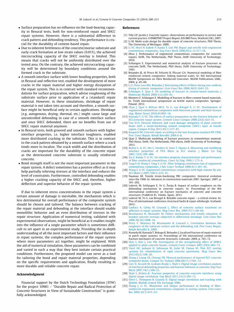
Here, a lattice type model [5] is used to simulate fracture per-formance of fiber reinforced repair material. Simulation of fiberreinforced concrete with a lattice type model was already appliedby Bolander et al. [6,7], where reduction of the shrinkage crackswith the addition of fibers was investigated. The presented modelis based on the principle of embedding discrete fibers in a randomlattice mesh representing the material matrix [8]. Different typesof fiber reinforcement, including wood fibers, can be simulated[9]. Herein, the influence of addition of polyvinyl alcohol-PVAfibers is examined and compared to non-reinforced material.
SHCC was first designed through numerical testing in a singlefiber pullout test and a direct tension test. In this way, input val-ues for the mechanical properties of the lattice elements are
M. Lukovic et al. / Cement & Concrete Composites 53 (2014) 200–213 201
determined. The influence of different material laws for thefiber/matrix interface elements on composite behavior andachieved crack density is investigated and compared to theexperimental results [10].
Once local material properties for the simulated repair materialare defined, structural behavior and debonding tendency of therepair system is investigated. Cracking or debonding of the overlayreduces the load-carrying capacity of the overlay system andallows water and other hazardous substances to penetrate intoconcrete. Predicting and quantifying the performance of overlaywill, therefore, enable more reliable estimation about efficiencyand service life of the repair system. It is well recognized that sur-face preparation and interface status between SHCC and substrateconcrete are important parameters when designing a repair system[11–13]. Therefore, the influence of these parameters on the result-ing fracture performance of the repair system, both for reinforcedand non-reinforced repair material is investigated. Since existingcracks or joints in the old material are initiation points for cracklocalization in repair material (reflective cracking), the possibilityof suppressing these cracks is also investigated.
2. Lattice model
Fracture processes of cement-based materials can be simulatedwith lattice models [8,14]. In these models, the material is discret-ized as a network of truss or beam elements connected at the ends.Usually all the single elements have linear elastic properties. Ineach loading step, an element that exceeds the limit stress or straincapacity is removed from the mesh. The analysis procedure is thenrepeated until a pre-determined failure criterion for the simulatedspecimen is achieved. In this way realistic crack patterns can beobtained. Further on, although each element has brittle behavior,structural softening and ductile global behavior can be simulated.
The procedure to generate the network is as follows:
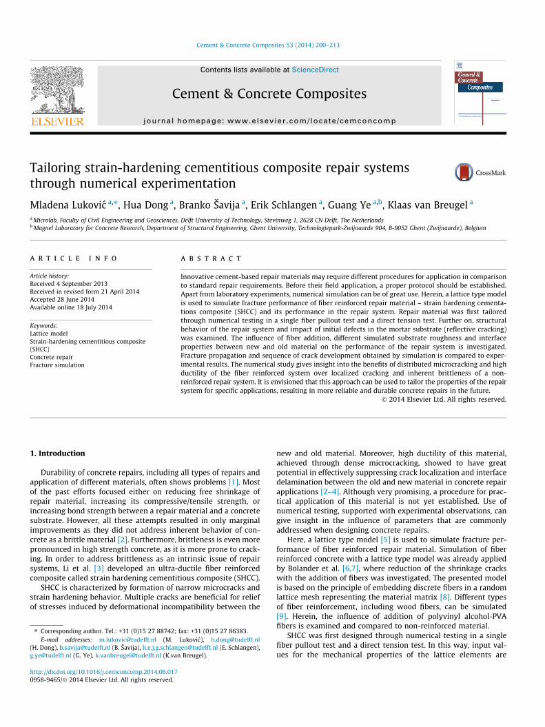
� A cubical grid is chosen (square for 2D lattice).� In each cell of the square (cube for 3D lattice), a random loca-
tion for a lattice node is selected. First the nodes are randomlypositioned inside a sub cell of size s in a regular grid with size A(Fig. 1). The ratio s/A is defined as randomness of a lattice andhere it is set to be 0.5. This means that some disorder is builtinto the lattice mesh itself.� Always the three nodes (four nodes for 3D) which are closest to
each other are connected by beam elements using Delaunaytriangulation. Each node of the 3D system has 6 degrees of free-dom (3 translations and 3 rotations).� The beams which belong to each phase are identified by
overlapping material layers (i.e. concrete/mortar substrate andrepair material) on top of the lattice. Interface elements are
Fig. 1. Two-dimensional overlay procedure for generation of th
generated between substrate nodes and repair material nodes.In Fig. 1, generation of interface elements for the smooth andrough (grooved) substrate surface is presented.� Fiber elements are added in the repair material according to a
chosen volume content (2% by volume in case of SHCC), fiberlength and diameter. The location of the first node of each fiberis chosen randomly in the specified volume and a random direc-tion is defined which determines the position of the secondnode. If the second node is outside of the mesh boundary, thenit is automatically cut off and accounted for in order to ensurepreservation of prescribed volume content.� Extra nodes inside the fibers are generated at each location
where the fiber crosses the square (in 3D cubical) grid.� Fiber interface elements are generated between fiber nodes and
the matrix nodes in the neighboring cell. Also, the end nodes ofthe fibers are connected with an interface element to the matrixnode in the cell where the fiber end is located (Fig. 1).� Different mechanical properties are ascribed to the elements of
the repair material, fibers and fiber/repair material interface, asindicated in Table 1. Fiber properties are adopted from litera-ture [15]. Repair material and fiber/repair material interfaceproperties are fitted from simulated pullout test and direct ten-sion test. These are compared to experimental results obtainedat specimens’ age of 28 days [2,10] (see Section 3).� An element can fail either in tension or in compression, when
the stress exceeds its strength. For the fracture criterion, onlyaxial forces are taken into account to determine the stress inthe beams.
In all simulations presented herein, linear dimension of thecubical grid used for mesh generation (see Fig. 1) is 1 mm. Valuesfor the mechanical properties for interface elements which connectrepair material and mortar substrate (Table 1) are assumed values.As the interface is usually the weakest zone in the system, lowerproperties are ascribed to elements which characterize this zone.For simplicity, it was also assumed that the mortar substrate hasthe same mechanical properties as the repair material matrix.Although in real repair systems this is not the case, here it wasdone in order to avoid additional influence of this parameter onthe response of the system.
3. Tailoring repair material and discussion
3.1. Pullout test
Proper design of strain hardening behavior of SHCC is achievedthrough tailoring of the matrix/fiber interface properties. When thecrack starts opening, fibers are activated, take over the tensile forceover the crack surfaces and, along their interface, transfer it into
e lattice model for the grooved and smooth surface profile.
Table 1Input values for the lattice model.
Element Radius E (GPa) ft (MPa) fc (MPa)
Matrix (repair material-RM) 0.44 20 3.5 �10 ft
Fiber [14] 0.02 40 1640 �ft
Interface (Matrix/Fiber) 0.04 20 10 �10 ft
Mortar substrate (MS) 0.44 20 3.5 �10 ft
Interface (MS/RM) 0.44 15 1 �10 ft
2
202 M. Lukovic et al. / Cement & Concrete Composites 53 (2014) 200–213
the surrounding matrix. These matrix/fiber interface properties,therefore, have a critical influence on achieved fiber-bridgingcapacity. As a consequence, development of SHCC performancestarts with testing [15] and modeling [16] of a single fiber pull-out behavior.
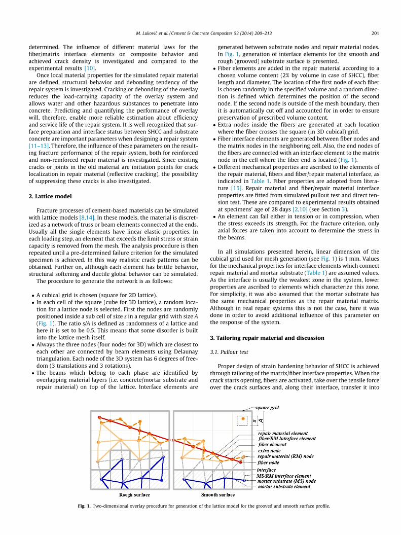
During a pull-out test, one fiber is pulled-out from the matrixwhile the load (P) vs. displacement (d) relation is recorded. A sche-matic illustration of a single fiber pullout behavior is shown inFig. 2. When a fiber is subjected to a pullout force, first stable deb-onding takes place between the fiber and the matrix zone. Thecrack gradually propagates along the interface until it reachesthe maximum pullout resistance Pa. An unstable extension of theinterface crack causes the load to decrease from Pa to the pulloutfrictional load Pb [17]. The chemical bond between the fiber andmatrix is assumed to be broken, the fiber is completely debondedand the pullout stage begins. In this stage, only frictional forcesresist the fiber slippage. Depending on a relative hardness of thefiber and the matrix, as well as the curvature of the fiber in thecement matrix, there are three possible behaviors of the fiber:sliding with slip hardening (b > 0), constant friction (b = 0) or slipsoftening (b < 0). Slip hardening occurs with polymer fibers,including PVA fibers used for SHCC. These fibers are flexible andless hard than the surrounding matrix. As a consequence, ajamming effect during fiber sliding can take place in the matrix,leading to an increasing load resisting fiber pullout [2,17]. Thisphenomenon of increased shear resistance during the pulloutphase is very beneficial as long as the fiber tensile strength is notexceeded which would lead to brittle fiber rupture.
In order to determine matrix/fiber interface properties to beused in simulations, pullout of a single, 9 mm long fiber is numer-ically tested by lattice model. A cement-matrix specimen withdimensions of 9 � 9 � 9 mm is fixed at its bottom surface while ahalf embedded fiber is pulled out by its free end (Fig. 4a). As aresult, measured deformation, apart from fiber pull-out, includesalso the deformation of the matrix and elongation of the fiber.Since the pull-out test only affects interface elements, no cracksappear in the cement matrix.
Two different material laws for the interface elements aretested in the simulation (Fig. 3). First, an interface element is
Fig. 2. General profile of a si
simulated as brittle. This means that after reaching its strength,the element breaks, and is removed from the mesh. In the secondcase, the interface element is simulated as ductile. This means thatthe element is not immediately removed from the mesh uponreaching its strength, but its stiffness gradually decreases over anumber of analysis steps, following the material law presented inFig. 3.
In Fig. 4, pullout curves, both for ductile and brittle material lawfor the interface elements, are presented. The points are chosen forwhich the snapshots of the crack history during the pullout test aremade. These are given in Fig. 5.
When a brittle material law is used, in the first (elastic) stage,gradual debonding of the fiber element starts as the pullout forceincreases. Interface elements which are aligned more vertically(i.e. in the direction of the load), break first. Until reaching the peakforce, no continuity in the interface crack is observed (Fig. 5b). Everynode of the fiber is still connected to matrix. Once, the continuitybetween the cracked elements is achieved (Fig. 5c), i.e. all elementsconnecting a certain fiber node with the matrix are broken, there is asudden drop in the force. The fiber is continuously debonded andresidual linking interface elements further break. As can be seenfrom the diagram (Fig. 4), after reaching the peak load, the pulloutresponse is very brittle. In order to enable more ductility of thefiber-matrix system in the pullout stage and more stable behavior,ductile material law for the interface elements is needed.
When ductile material law is used, the initial stage of the pull-out curve, before development of continuous debonding, is thesame as for the brittle law (Fig. 4b-step b and c). However, afterthis initial stage, when the force suddenly decreases, the pulloutbehavior is significantly altered (Fig. 4b-step d). Since interface ele-ments are not removed after reaching their predefined strength,they can still transfer stresses, and the strain hardening behaviorin the slipping stage of the fiber is reproduced. More ductilityand constant friction stresses during complete fiber sliding isachieved. Segments in the ductile material law are, then, adjustedaccording to the global pull-out curve, such that the interface shearstress is around 3 MPa as obtained in experiments at the speci-mens age of 28 days [2,16]. The interface shear stress (s) can becalculated from the pull-out load (P) and the surface area of theembedded fiber that is in contact with the cement matrix (Eq. (1)).
s ¼ PLepdf
ð1Þ
Due to the node randomness and the limited number of interfaceelements, different element alignment causes some variation ofthe results in the simulated pull-out test. Therefore, pull-out testsfor 4 randomly generated meshes are simulated and results arepresented in Fig. 6.
The results show that the elastic parts of the pullout curves aresimilar, but there are variations in the peak forces, which are a
ngle fiber pullout curve.

Fig. 3. Brittle (left) and ductile (right) material law for the interface elements.
Fig. 4. (a) Specimen set-up, (b) pullout curve for the brittle and ductile material law.
M. Lukovic et al. / Cement & Concrete Composites 53 (2014) 200–213 203
consequence of the applied modeling concept. These heterogene-ities of the results are due to random alignment of interface ele-ments which connect fibers with the matrix elements. In eachsimulation, different alignment of the interface elements is gener-ated. Interface elements which have smaller alignment angle withthe fiber will break sooner, and can take less force than those ele-ments perpendicular to the fiber. The alignment will also deter-mine the sequence of cracking and the connectivity of brokeninterface elements. These variations could be avoided either byrefining the lattice mesh, which would lead to longer computationtime, or by decreasing randomness value of the lattice mesh (s/A,see Fig. 1). This would, however, affect the inherent global hetero-geneity of the represented material. In addition, in the first, elasticstage, which is almost the same for all 4 generated meshes (regard-less whether brittle or ductile material law is applied for interfaceelements), fiber slipping is small and in the range of crack widthswhich are typical for SHCC. Therefore, it is believed that this firststage, where the pull-out behavior is almost independent on themesh and the applied material law, is very important for simulat-ing the general microcracking tendency and strain-hardeningbehavior of SHCC. However, when the fiber becomes continuouslydebonded, depending on the mesh randomness, connectivity,alignment and local material law of the interface elements, varia-tions in the maximum pull-out strength and ductility increase.Material law is one of the parameters which shows the most signif-icant influence on variations in this stage and is therefore furtheraddressed in the paper. Implications of different post-peak behav-ior in pullout test on the microcracking tendency and final crackpattern in direct tension test are discussed in next chapter.
3.2. Direct tension test (SHCC and non-fiber reinforced material)
When SHCC is loaded in tension, the matrix starts to crack in itsweakest cross-section. As the crack propagates, fibers crossing that
crack take over the tensile load. As long as the fiber does not break,slip hardening behavior characteristic for PVA fibers is beneficialfor satisfying an energy-based failure criterion, which enables thatcracks propagate in a steady-state flat cracking mode [18]. Provid-ing that matrix cracking strength does not exceed fiber-bridgingstrength at the location of the crack, also a stress-based failure cri-terion is satisfied and a new crack will open at another location.When these two criteria are fulfilled, successive cracking insteadof single crack localization is achieved [19]. Consequently, tightlyspaced cracks which contribute to high material ductility andstrain hardening behavior are produced. This behavior makes themain difference between SHCC and conventional fiber reinforcedor monolithic concrete.
A similar tendency is observed in simulated experiments. Here,three prismatic specimens (plain concrete, SHCC with brittle inter-face elements, and SHCC with ductile interface elements) withdimensions of 15 � 5 � 60 mm were subjected to a direct tensiontest. PVA fibers (2% by volume, length 8 mm, diameter 0.04 mm)are embedded in repair matrix according to the procedure describedin Section 2. Specimens were loaded by prescribing a verticaldisplacement at the upper edge, while rotations and in-plane trans-lations at the top and bottom edge were constrained. The stress–strain diagrams are plotted in Fig. 7. When no fibers are used, a singlecrack plane develops, followed by a steep stress reduction and a brit-tle failure at low ultimate tensile strain. However, in SHCC, after theformation of the first crack, material still withstands stresses. Thishappens because, once the crack starts opening, fibers are activated.Fibers act as a group, randomly orientated and distributed withrespect to the crack surfaces, taking over the stresses and arrestingthe crack. After the initial drop caused by crack formation, fibersassure that uniaxial stress increases again and allow for moreconsecutive cracks to be formed.
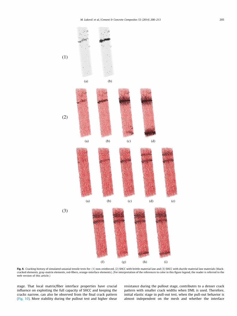
In Fig. 7, points are chosen for which the snapshots of the crackhistory are made and compared. These snapshots are given in

Fig. 5. Crack development during the pullout test (red-fiber, orange-intact interface, gray-matrix, black-broken elements)-the sequence is the same both for ductile andbrittle law. (For interpretation of the references to color in this figure legend, the reader is referred to the web version of this article.)
Fig. 6. Pullout test for different mesh generation. Fig. 7. Tensile stress strain curves for simulated specimens (up to 0.2% strain).
204 M. Lukovic et al. / Cement & Concrete Composites 53 (2014) 200–213
Fig. 8. Each of the drops in the stress–strain curve represents amoment when a single crack is localized. In cases where the brittlematerial law is applied for the interface elements (BML), less crack-ing is achieved. Wider cracks with larger spacing form, and crackshave more tendency to localize. However, if a ductile material law(DML) is used, interface elements do not break immediately, andthis allows for more cracks with smaller spacing and smaller crackwidths to form. As interface elements can still transfer shear stres-ses after reaching peak strength, they enable more stable crackpropagation with more cracks at the same strain level.
Simulation results are compared to experimental results ofZhou when mixture M6 was used [10] (Fig. 9). Mix proportion ofM6 is given in Table 2.
It can be seen from Fig. 9 that, both ductile and brittle materiallaw can simulate the required ductility and microcracking behav-ior of the material. However, with a ductile material law the uniax-ial tensile stress after first cracking is higher than predicted withthe brittle material law. This is because higher shear resistanceat the contact between fibers and matrix enables that more stresscan be transferred through these elements during the pullout
(a) (b)
(a) (b) (c) (d)
(a) (b) (c) (e)(d)
(f) (g) (h) (i)
(2)
(1)
(3)
Fig. 8. Cracking history of simulated uniaxial tensile tests for: (1) non-reinforced, (2) SHCC with brittle material law and (3) SHCC with ductile material law materials (black-cracked elements, gray-matrix elements, red-fibers, orange-interface elements). (For interpretation of the references to color in this figure legend, the reader is referred to theweb version of this article.)
M. Lukovic et al. / Cement & Concrete Composites 53 (2014) 200–213 205
stage. That local matrix/fiber interface properties have crucialinfluence on exploiting the full capacity of SHCC and keeping thecracks narrow, can also be observed from the final crack pattern(Fig. 10). More stability during the pullout test and higher shear
resistance during the pullout stage, contributes to a denser crackpattern with smaller crack widths when DML is used. Therefore,initial elastic stage in pull-out test, when the pull-out behavior isalmost independent on the mesh and whether the interface

Fig. 9. Tensile stress–strain curves for simulated SHCC compared with experimen-tal results for mixture M6 [10].
206 M. Lukovic et al. / Cement & Concrete Composites 53 (2014) 200–213
elements are modeled as brittle or ductile, is very important forsimulating the general microcracking behavior of SHCC. On theother hand, the pull-out behavior after this stage, which corre-sponds to higher fiber slipping and shows variation for differentmeshes and material laws, has an influence on final crack patternand crack spacing (Fig. 10).
In both cases, failure occurred when one crack localizes, wherefibers were completely pulled out and broken. However, finalcracks did not localize at the same location, which is due to differ-ent positions of the previously formed cracks and, therefore, differ-ent stress distributions. Since ductile interface elements providebetter representation of the performance of SHCC, and betterreproduce the formation of narrow, closely spaced cracks, a ductilematerial law for the interface elements is used in further analyses.
Table 2Mix proportion of M6 (weight%) [9].
CEM I 42.5N Limestone powder Blast furnace slag Wa
1 3.33 2.33 0.2
Fig. 10. Final crack pattern of simulated samples (a and b) with BML and DM
4. Performance of the repair system and discussion
4.1. Flexural test
A three point bending test is used to examine the structuralbehavior and debonding tendency of the composite repair-sub-strate system. Surface roughness is considered to have the great-est influence on bond strength and performance of the repairsystem. However, the influence of this parameter is not quiteclear, nor there exist the clear relationship between the rough-ness parameters and adhesion in the repair system [20]. Thiscan be attributed to the complexity of the problem, as the deb-onding mechanism and the bond strength depend on a variety ofmaterial parameters and environmental conditions [21]. Sincethese factors are interdependent, it appears very difficult toexperimentally separate one and independently observe its influ-ence. That is why the use of a numerical simulation is beneficial,enabling the insight into the influence of just one parameterwhile keeping the others constant. Beside the influence of sur-face roughness, also the influence of the interface properties(i.e. between old and new material) and incorporation of thefibers in the repair material on the crack propagation and frac-ture performance of the repair system are examined.
The dimension of the simulated beam specimen for the bendingtest is 15 � 15 � 60 mm with 5 mm thickness of the repair overlay.SHCC tailored in the pullout and direct tension test is used as arepair material (overlay). For comparison, also repair materialwithout fibers is tested. For the elements that represent mortarsubstrate and interface, input values from Table 1 are used. Thespecimen in three point bending test is loaded by prescribing ver-tical displacements in the middle. The specimen is simply sup-ported at the ends.
ter/powder ratio Super-plasticizer PVA fiber (by volume, %)
6 0.033 2
L respectively and (c) tested [16] (only matrix elements are presented).

Fig. 11. Simulated surface profiles.
Fig. 12. Simulated force–deflection diagram in three point bending for differentroughness profiles with SHCC and non-reinforced repair material.
M. Lukovic et al. / Cement & Concrete Composites 53 (2014) 200–213 207
Three different surface roughness profiles are imitated in orderto simulate roughness that is usually prepared in the experiments(Fig. 11). The relative influence of the groove size compared to themesh size was addressed in previous work [20]. There, the influ-ence of the roughness profiles with different grooves’ widths andheights on resulting bond strength (i.e. in direct tension test andshear test) and structural performance of the repair system (i.e.in three point bending test) was investigated. In this work, thewidth of grooves was varied in order to see how roughness param-eter affects the performance of the repair system. If compared,grooved surface 2 represents the lower frequency roughness withthe same amplitude parameter as grooved surface 1 [20,22,23].
The load–deflection curves for all types of surface profiles (up to0.1 mm deflection), with and without fibers, are presented inFig. 12. There is a substantial difference in performance of the sys-tem depending on whether fibers are included or not. First (elastic)part of the force–deflection curve is the same, and it depicts themoment until the first crack occurs. The load when the first crackoccurs in the reinforced sample is equal to the first cracking loadof non-reinforced system. From this point, the difference in behav-ior of two systems becomes obvious. In repair system with nofibers, initial crack propagates rapidly, which results in steep loadreduction. This is followed by a brittle failure at low deflection val-ues. A single crack plane that develops determines the perfor-mance of the system. On the contrary, if fibers are included (i.e.SHCC is used), after certain crack opening, fibers crossing that crackbecome activated, take the load, and prevent that cracks furtherpropagate. Consequently, they enable stress concentration to shiftto another location, where a new crack starts developing. Further-more, although substantially cracked, the sample can stillwithstand stresses and act monolithically. Fibers allow the repairsystem to show more ductility and avoid brittle failure, which is
necessary for reliable repair. Improving system ductility via fiberimplementation is crucial, as most composite systems are notcrack free structures (either because of early age deformations,drying, dimensional incompatibility and/or defects in concretesubstrate), and their behavior is strongly dependent on fractureproperties after reaching the peak load.
According to force–deflection diagrams, there is almost no dif-ference in response of the system with different simulated rough-ness, both for non-reinforced material and SHCC. Maximum forcefor all three SHCC specimens is virtually the same (maximum dif-ference 1.41%). The same holds for the non-reinforced specimenswhere different surface preparation seems to have no influenceon the bearing capacity (difference in maximum force 1.13%).However, when crack patterns are compared, for plain specimenswith different surface preparations, some differences can beobserved (Fig. 13). It seems that, although it does not decreasethe load-bearing capacity, smooth surface exhibits larger debond-ing length for the same local interface properties compared torougher surfaces. From purely geometrical point of view, groovesenable higher mechanical anchorage and more monolithicresponse with less amount of debonding. Same was observed in[24], where, under static loading, the measured relation betweendeflection and load for different types of surface preparation wasthe same. However, the debonding length for surfaces preparedby scarification (relatively smooth surface) was substantiallyhigher than for surface prepared by sandblasting and hydrojetting(rough surface). Their conclusion was that roughness does notincrease bearing capacity of composite elements, but enables moremonolithic response and reduces probability of debonding. Pre-sented results further substantiate this claim.
A similar tendency is observed also for SHCC repair system.Smooth surface enables higher energy loss on debonding. In thesimulation, it enables more cracks to open, which increases theductility of the system (Figs. 14 and 15a). In this case interfacedebonding is beneficial, as it enables more stress redistributionand utilizes more material to resist the final fracture. A similartrend was detected by Kunieda et al [25], who deliberately intro-duced some debonding between the substrate and SHCC overlayprior to mechanical testing. It was found that this did not affectthe load–displacement curves, but the length of the distributedcrack zone on the specimen bottom was longer than in specimenswithout an unbounded region. This was attributed to a largerunrestrained area of the SHCC which could contribute to high freedeformation (i.e. without being restrained by the concrete sub-strate) when some debonding introduced.
With smooth substrate, cracks in the repair material do notpropagate directly through the substrate, as there is no sufficient
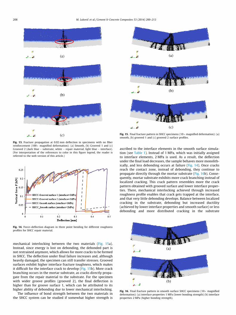
Fig. 13. Fracture propagation at 0.02 mm deflection in specimens with no fiberreinforcement (100� magnified deformation): (a) Smooth, (b) Grooved 1 and (c)Grooved 2 (dark blue – substrate, white – repair material, light blue – interface).(For interpretation of the references to color in this figure legend, the reader isreferred to the web version of this article.)
Fig. 14. Force–deflection diagram in three point bending for different roughnessprofiles for SHCC repair material.
Fig. 15. Final fracture pattern in SHCC specimens (10�magnified deformation): (a)smooth, (b) grooved 1 and (c) grooved 2 surface profiles.
Fig. 16. Final fracture pattern in smooth surface SHCC specimens (10� magnifieddeformation): (a) interface properties 1 MPa (lower bonding strength) (b) interfaceproperties 2 MPa (higher bonding strength).
208 M. Lukovic et al. / Cement & Concrete Composites 53 (2014) 200–213
mechanical interlocking between the two materials (Fig. 15a).Instead, since energy is lost on debonding, the debonded part isnot restrained anymore, which allows for more cracks to be formedin SHCC. The deflection under final failure increases and, althoughheavily damaged, the specimen can still transfer stresses. Groovedsurfaces exhibit higher interface fracture toughness, which makesit difficult for the interface crack to develop (Fig. 15b). More crackbranching occurs in the mortar substrate, as cracks directly propa-gate from the repair material to the substrate. For the specimenwith wider groove profiles (grooved 2), the final deflection ishigher than for groove surface 1, which can be attributed to itshigher ability of debonding due to lower mechanical interlocking.
The influence of bond strength between the two materials inthe SHCC system can be studied if somewhat higher strength is
ascribed to the interface elements in the smooth surface simula-tion (see Table 1). Instead of 1 MPa, which was initially assignedto interface elements, 2 MPa is used. As a result, the deflectionunder the final load decreases, the sample behaves more monolith-ically, and less debonding occurs at failure (Fig. 14). Once cracksreach the contact zone, instead of debonding, they continue topropagate directly through the mortar substrate (Fig. 16b). Conse-quently, mortar substrate exhibits more crack branching instead oflocalized cracking. This crack pattern resembles more the crackpattern obtained with grooved surface and lower interface proper-ties. There, mechanical interlocking achieved through increasedroughness profile enables that crack gets trapped at the interface,and that very little debonding develops. Balance between localizedcracking in the substrate, debonding but increased ductility(achieved by lower interface properties and smooth surface) or lessdebonding and more distributed cracking in the substrate

Fig. 17. Specimen for digital image correlation (DIC) with the interface profiles: (b) groove (up) and smooth (down).
Fig. 18. Force deflection/crack opening diagrams for simulated (a) and tested (b) samples (Grooved surface-DIC is the specimen which was processed by DIC technique).
M. Lukovic et al. / Cement & Concrete Composites 53 (2014) 200–213 209
(achieved by increased interface fracture toughness) will governthe final failure mode of the repair. Also, as these cracks are pathsfor penetration of water and hazardous substances, they eventuallygovern the durability performance of the repair system. Controllingthe way that substrate cracks and debonding can be used to designrepair systems which satisfy predefined requirements, and thesemight differ from system to system.
If compared to experimental results from the literature[12,26–28], simulated curves for three point bending test (Figs. 12and 14) are too brittle. This is due to the brittle failure mode,which is ascribed to the single elements. In reality, cracked sur-faces can still transfer some forces due to the closure of the crackwhen compressive loading is applied. Therefore, due to the fric-tion between crack faces, stresses can still be transferred andthe sample exhibits a certain amount of plasticity. In the model,however, this plasticity is not present because the elements(except for fiber/matrix interface elements), which have failed,are immediately removed from the mesh, and cannot transferforces anymore. Therefore, after the crack propagates to the top,elements around the zone where the load is applied are brokenin compression, and cannot transfer forces anymore. As a conse-quence of crushing of this zone where load is applied, brittle fail-ure mode without plasticity and with steep load reduction isobtained. Since the boundary conditions, generated mesh andfinal failure mode are the same for all the simulated specimens,final deflections and crack pattern between the specimens withdifferent surface preparations can still be critically examined.Therefore, care must be taken when quantitatively assessing theanalysis results, since some model limitations apply.
In order to exhaust full capacity of SHCC repair, lower interfacetoughness might be beneficial, as it enables more stress reductionthrough consecutive crack opening and higher ductility of the sys-tem. On the other hand, one must be aware that, in these mechan-ical simulations, influence of shrinkage is not considered. Inlaboratory experiments, also, specimens are usually well curedprior to testing, which reduces the amount of early age dryingshrinkage of the repair material. In reality, shrinkage cannot beexcluded, and specimens prior to mechanical test would have akind of prestresses due to this deformational pre loading. A roughsurface will provide more restrain to early age shrinkage and lessdamage will occur at the interface. More fracture energy will belost, and even after first cracking, rough surface will enable somestress transfer through the friction between crack faces [20]. Onthe other hand, if a smooth surface is used, the bond betweenrepair material and the substrate might be damaged to the extentthat no further stresses can be withstood at the interface, and thiswould result in failure of the repair, before the benefits of distrib-uted cracking of the repair material can even be utilized. Once deb-onded, repair material loses its bond with the substrate, and thereare no benefits from the fiber reinforcement anymore. Conse-quently, the presented results reflect the laboratory studies well,while in field practice, additional factors could play a role. Address-ing the influence of drying shrinkage prior to mechanical testingwill be a part of further study.
4.1.1. Experimental verificationIf full capacity of a repair material is to be used, the cracking
process in the repair system needs to be understood. Results

Fig. 19. Crack propagation in simulated (a) and tested (b) grooved surface sample with final crack pattern (c) obtained after testing when sample fluorescent epoxyimpregnated and cut in the middle.
210 M. Lukovic et al. / Cement & Concrete Composites 53 (2014) 200–213
obtained in simulations need to be verified and compared to exper-imental data. An important step is to check whether simulatedcrack development corresponds well with experimental results.Simulated crack growth is correlated and compared to crackgrowth in experimental observations. In experiments, digitalimage correlation (DIC) technique is used for capturing deforma-tion levels in repair system. This is a non-contact optical methodthat employs tracking and image registration techniques for accu-rate 2D measurements of changes in images. This allows calculat-ing deformation, displacement and strain on the observed surface(Fig. 17). More details regarding this procedure can be foundelsewhere [29–31].
Composite beam samples with a support span of 110 mm weretested under three point bending (Fig. 17). Mixture M6 (Table 2)was used as a repair material. The applied load and the crack open-ing mouth displacement (CMOD) in the middle part of the speci-men (within the repair material) for specimens with smooth andgrooved type of surface preparation were recorded. In order toenable stable crack propagation, crack opening displacement con-trol is used. When crack opening reached 0.8 mm, specimens wereunloaded. The digital image correlation procedure was performedfor a grooved specimen surface. In order to reduce the additionalinfluence of the local heterogeneity of the sample, mortar substrateinstead of concrete was used. The dimensions of the tested samples
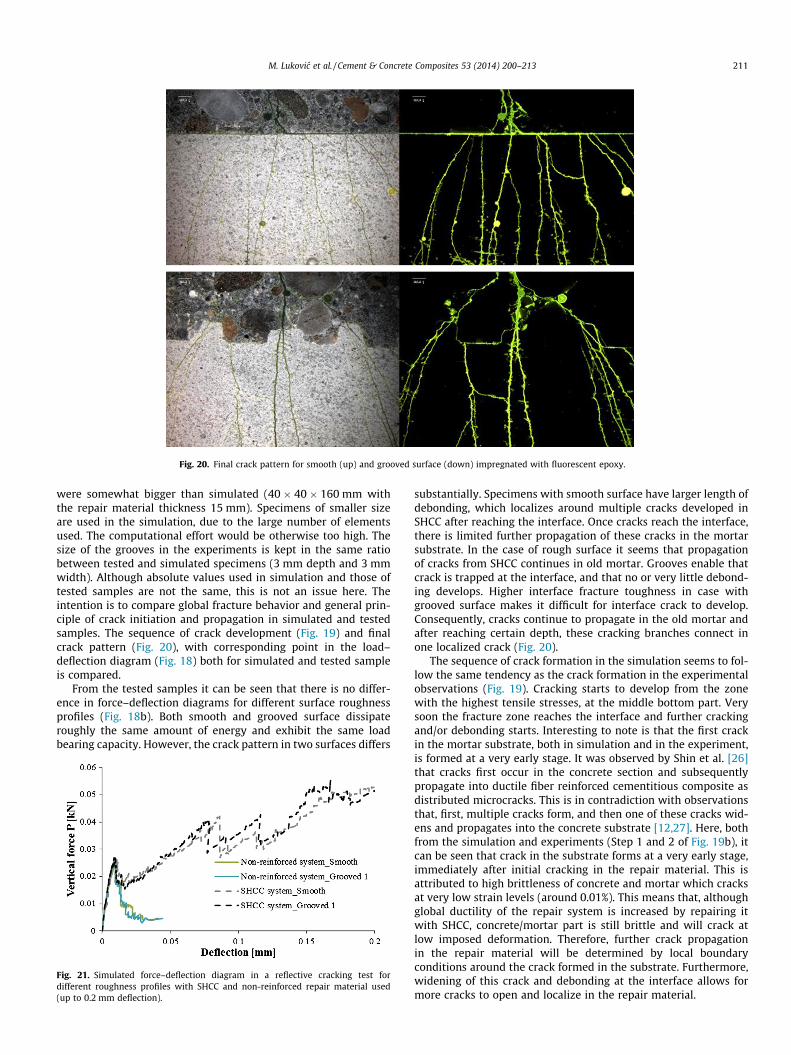
Fig. 20. Final crack pattern for smooth (up) and grooved surface (down) impregnated with fluorescent epoxy.
M. Lukovic et al. / Cement & Concrete Composites 53 (2014) 200–213 211
were somewhat bigger than simulated (40 � 40 � 160 mm withthe repair material thickness 15 mm). Specimens of smaller sizeare used in the simulation, due to the large number of elementsused. The computational effort would be otherwise too high. Thesize of the grooves in the experiments is kept in the same ratiobetween tested and simulated specimens (3 mm depth and 3 mmwidth). Although absolute values used in simulation and those oftested samples are not the same, this is not an issue here. Theintention is to compare global fracture behavior and general prin-ciple of crack initiation and propagation in simulated and testedsamples. The sequence of crack development (Fig. 19) and finalcrack pattern (Fig. 20), with corresponding point in the load–deflection diagram (Fig. 18) both for simulated and tested sampleis compared.
From the tested samples it can be seen that there is no differ-ence in force–deflection diagrams for different surface roughnessprofiles (Fig. 18b). Both smooth and grooved surface dissipateroughly the same amount of energy and exhibit the same loadbearing capacity. However, the crack pattern in two surfaces differs
Fig. 21. Simulated force–deflection diagram in a reflective cracking test fordifferent roughness profiles with SHCC and non-reinforced repair material used(up to 0.2 mm deflection).
substantially. Specimens with smooth surface have larger length ofdebonding, which localizes around multiple cracks developed inSHCC after reaching the interface. Once cracks reach the interface,there is limited further propagation of these cracks in the mortarsubstrate. In the case of rough surface it seems that propagationof cracks from SHCC continues in old mortar. Grooves enable thatcrack is trapped at the interface, and that no or very little debond-ing develops. Higher interface fracture toughness in case withgrooved surface makes it difficult for interface crack to develop.Consequently, cracks continue to propagate in the old mortar andafter reaching certain depth, these cracking branches connect inone localized crack (Fig. 20).
The sequence of crack formation in the simulation seems to fol-low the same tendency as the crack formation in the experimentalobservations (Fig. 19). Cracking starts to develop from the zonewith the highest tensile stresses, at the middle bottom part. Verysoon the fracture zone reaches the interface and further crackingand/or debonding starts. Interesting to note is that the first crackin the mortar substrate, both in simulation and in the experiment,is formed at a very early stage. It was observed by Shin et al. [26]that cracks first occur in the concrete section and subsequentlypropagate into ductile fiber reinforced cementitious composite asdistributed microcracks. This is in contradiction with observationsthat, first, multiple cracks form, and then one of these cracks wid-ens and propagates into the concrete substrate [12,27]. Here, bothfrom the simulation and experiments (Step 1 and 2 of Fig. 19b), itcan be seen that crack in the substrate forms at a very early stage,immediately after initial cracking in the repair material. This isattributed to high brittleness of concrete and mortar which cracksat very low strain levels (around 0.01%). This means that, althoughglobal ductility of the repair system is increased by repairing itwith SHCC, concrete/mortar part is still brittle and will crack atlow imposed deformation. Therefore, further crack propagationin the repair material will be determined by local boundaryconditions around the crack formed in the substrate. Furthermore,widening of this crack and debonding at the interface allows formore cracks to open and localize in the repair material.
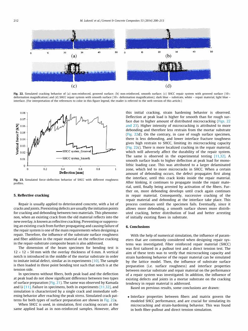
Fig. 22. Simulated cracking behavior of (a) non-reinforced, grooved surface; (b) non-reinforced, smooth surface; (c) SHCC repair system with grooved surface (10�deformation magnification) and (d) SHCC repair system with smooth surface (10� deformation magnification); dark blue – substrate, white – repair material, light blue –interface. (For interpretation of the references to color in this figure legend, the reader is referred to the web version of this article.)
Fig. 23. Simulated force–deflection behavior of SHCC with different roughnessprofiles.
212 M. Lukovic et al. / Cement & Concrete Composites 53 (2014) 200–213
5. Reflective cracking
Repair is usually applied to deteriorated concrete, with a lot ofcracks and joints. Preexisting defects are usually the initiation pointsfor cracking and debonding between two materials. This phenome-non, when an existing crack from the old material reflects into thenew overlay, is known as reflective cracking. Preventing or suppress-ing an existing crack from further propagating and causing failure ofthe repair system is one of the main requirements when designing arepair. Therefore, the influence of the substrate surface roughnessand fiber addition in the repair material on the reflective crackingin the repair-substrate composite beam is also addressed.
The dimension of the beam specimen for bending test is12 � 12 � 50 mm with the overlay thickness of 6 mm. A verticalnotch is introduced in the middle of the mortar substrate in orderto imitate initial defect, similar as in experiments [10]. The sampleis then loaded in three point bending test such that notch is at thetension side.
In specimens without fibers, both peak load and the deflectionat peak load do not show significant difference between two typesof surface preparation (Fig. 21). The same was observed by Kamadaand Li [11]. Failure in specimens, both in experiments [11,32], andsimulation is characterized by a single crack and immediate soft-ening behavior after reaching the peak stress. Simulated crack pat-terns for both types of surface preparation are shown in Fig. 22a.
When SHCC is used, in simulation, first cracking occurs at thesame applied load as in non-reinforced samples. However, after
this initial cracking, strain hardening behavior is observed.Deflection at peak load is higher for smooth than for rough sur-face due to higher amount of distributed microcracking (Figs. 22and 23). Higher intensity of microcracking is attributed to moredebonding and therefore less restrain from the mortar substrate(Fig. 22d). On the contrary, in case of rough surface specimen,there is less debonding, and lower interface fracture toughnessgives high restrain to SHCC, limiting its microcracking capacity(Fig. 22c). There is more localized cracking in the repair material,which will adversely affect the durability of the repair system.The same is observed in the experimental testing [11,32]. Asmooth surface leads to higher deflection at peak load for mono-lithic loading case. This was attributed to a larger delaminatedzone, which led to more microcracks in SHCC. When a certainamount of debonding occurs, the defect propagates first alongthe interface, until this crack kinks inside the repair material.After kinking, it continues to propagate inside the repair mate-rial, until, finally being arrested by activation of the fibers. Fur-ther on, more debonding develops until crack again continuesin repair material. Consequently, successive cracking of therepair material and debonding at the interface take place. Thisprocess continues until the specimen fails. Eventually, since itallows more debonding, a smooth surface shows more distrib-uted cracking, better distribution of load and better arrestingof initially existing flaws in substrate.
6. Conclusions
With the help of numerical simulation, the influence of param-eters that are commonly considered when designing repair sys-tems was investigated. Fiber reinforced repair material (SHCC)was first tailored in a pullout test and a direct tension test. Theaim of these tests was to verify that microcracking capacity andstrain hardening behavior of the repair material can be simulatedby the lattice model. Then, the influence of substrate surfacepreparation (i.e. surface roughness) and interface propertiesbetween mortar substrate and repair material on the performanceof a repair system was investigated. In addition, the influence ofexisting defects and joints in a mortar substrate on the crackingtendency in repair material is addressed.
Based on previous results, some conclusions are drawn:
� Interface properties between fibers and matrix govern themodeled SHCC performance, and are crucial for simulating itsmicrocracking and strain-hardening behavior. This was foundin both fiber-pullout and direct tension simulation.
M. Lukovic et al. / Cement & Concrete Composites 53 (2014) 200–213 213
� Surface preparation has no influence on the load-bearing capac-ity in flexural tests, both for non-reinforced repair and SHCCrepair systems. However, there is a substantial difference incrack pattern and debonding tendency. This performance is cru-cial for the durability of cement-based repair.� Due to inherent brittleness of the concrete/mortar substrate and
early crack formation at low strain values (0.01%), the achievedmicrocracking capacity of the SHCC overlay is limited. Thismeans that cracks will not be uniformly distributed over thetested area. On the contrary, the achieved microcracking capac-ity will be determined by boundary conditions around theformed crack in the substrate.� A smooth interface surface with lower bonding properties, both
in flexural and reflective test, enabled the development of morecracks in the repair material and higher energy dissipation ofthe repair system. This is in contrast with standard recommen-dations for surface preparation, which advise roughening of thesubstrate surface prior to application of a (standard) repairmaterial. However, in these simulations, shrinkage of repairmaterial is not taken into account and therefore, a smooth sur-face might be beneficial only in certain applications. Shrinkage(e.g. autogenous, drying, thermal, etc.) might cause large anduncontrolled debonding in case of a smooth interface surfaceand once SHCC debonded, there are no benefits from use ofSHCC repair material anymore.� In flexural tests, both grooved and smooth surfaces with higher
interface properties, i.e. higher interface toughness, enabledmore distributed cracking in the substrate. This is in contrastto the crack pattern obtained by a smooth surface where a cracktends more to localize. The crack width and the distribution ofcracks are important for the durability of the concrete repairas the deteriorated concrete substrate is usually reinforcedconcrete.� Bond strength itself is not the most important parameter in the
repair system. A defect sometimes has a positive effect as it mayhelp partially relieving stresses at the interface and reduces thelevel of constraints. Furthermore, controlled debonding enablesa higher cracking capacity of the SHCC and, therefore, higherdeflection and superior behavior of the repair system.
If due to inherent stress concentrations in the repair system acertain amount of damage is inevitable, the mechanism which isless detrimental for overall performance of the composite systemshould be chosen and tailored. The balance between cracking ofthe repair material and debonding at the interface should enablemonolithic behavior and an even distribution of stresses in therepair structure. Application of numerical testing, validated withexperimental observations, might be beneficial as it enables insightinto the influence of a single parameter which is sometimes diffi-cult to set apart in an experimental study. Providing the in-depthunderstanding of all the most important factors and their influencein repair systems, the complex performance of the repair systemwhere more parameters act together, might be explained. Withthe aid of numerical simulation, these parameters can be combinedand varied in such a way that they best imitate certain practicalconditions. Furthermore, the proposed model can serve as a toolfor tailoring the bond and repair material properties, dependingon the specific requirements and application, finally resulting inmore durable and reliable concrete repair.
Acknowledgment
Financial support by the Dutch Technology Foundation (STW)for the project 10981 – ‘‘Durable Repair and Radical Protection ofConcrete Structures in View of Sustainable Construction’’ is grate-fully acknowledged.
References
[1] Tilly GP, Jacobs J. Concrete repairs: observations on performance in service andcurrent practice. CONREPNET Project Report, IHS BRE Press, Watford (UK); 2007.
[2] Li M. Multi-scale design for durable repair of concrete structures, PhD Thesis,The University of Michigan; 2009.
[3] Li VC, Horii H, Kabele P, Kanda T, Lim YM. Repair and retrofit with engineeredcementitious composites. Eng Fract Mech 2000;65(2–3):317–34.
[4] Zhou J. Performance of engineered cementitious composites for concreterepairs. Delft, The Netherlands, PhD Thesis, Delft University of Technology;2010.
[5] Schlangen E. Experimental and numerical analysis of fracture processes inconcrete Delft, The Netherlands, PhD thesis, Delft University of Technology;1993.
[6] Bolander JE, di Prisco M, Felicetti R, Plizzari GA. Numerical modeling of fiberreinforced cement composites: linking material scales. In: 6th InternationalRILEM Symposium on Fibre Reinforced Concretes: RILEM Publications SARL;2004. p. 45–60.
[7] Li Z, Perez Lara MA, Bolander J. Restraining effects of fibers during non-uniformdrying of cement composites. Cem Concr Res 2006;36(9):1643–52.
[8] Schlangen E, Qian Z. 3D modeling of fracture in cement-based materials. JMultiscale Modell 2009;1(2):245–61.
[9] Montero F, Schlangen E. Modelling of fracture in fibre-cement based materials.In: Tenth international symposium on brittle matrix composites. Springer:Poland; 2012.
[10] Zhou J, Qian S, Beltran MGS, Ye G, van Breugel K, Li VC. Development ofengineered cementitious composites with limestone powder and blast furnaceslag. Mater Struct 2010;43:803–14.
[11] Kamada T, Li VC. The effects of surface preparation on the fracture behavior ofECC/concrete repair system. Cement Concr Compos 2000;22(6):423–31.
[12] Yun H-D. Flexural behavior and crack-damage mitigation of plain concretebeam with a strain-hardening cement composite (SHCC) layer at tensileregion. Compos B Eng 2013;45(1):377–87.
[13] Raupach IM. Concrete repair according to the new European standard EN 1504.Proc Concr Repair, Rehab Retrofitt 2006:6–8.
[14] Qian Z. Multiscale modeling of fracture processes in cementitious material.PhD thesis. Delft, The Netherlands, PhD thesis, Delft University of Technology;2012.
[15] Redon C, Li VC, Wu C, Hoshiro H, Saito T, Ogawa A. Measuring and modifyinginterface properties of PVA fibers in ECC matrix. J Mater Civ Eng2001;13(6):399–406.
[16] Lin Z, Kanda T, Li VC. On interface property characterization and performanceof fiber-reinforced cementitious. Concr Sci Eng 1999;1:173–4.
[17] Yang E-H, Wang S, Yang Y, Li VC. Fiber-bridging constitutive law of engineeredcementitious composites. J Adv Concr Technol 2008;6(1):181–93.
[18] Wang S, Li VC. Engineered cementitious composites with high-volume fly ash.ACI Mater J 2007;104(3):233–41.
[19] Naaman AE. Tensile strain-hardening FRC composites: historical evolutionsince the 1960. In: Advances in construction materials 2007. Springer; 2007. p.181–202.
[20] Lukovic M, Schlangen E, Ye G, Šavija B. Impact of surface roughness on thedebonding mechanism in concrete repairs. In: Proceedings of the 8thinternational conference on fracture mechanics of concrete and concretestructures (FraMCoS-8). Toledo, Spain; 2013.
[21] Lukovic M, Ye G, van Breugel K. Reliable concrete repair – a critical review. In:Proc of international conference structural faults & repair edinburgh. Scotland;2012.
[22] Garbacz A, Górka M, Courard L. Effect of concrete surface treatment onadhesion in repair systems. Mag Concr Res. 2005;57(1):49–60.
[23] Beushausen H, Alexander M. Failure mechanisms and tensile relaxation ofbonded concrete overlays subjected to differential shrinkage. Cem Concr Res2006;36(10):1908–14.
[24] Perez F, Morency M, Bissonnette B, Courard L. Correlation between theroughness of the substrate surface and the debonding risk. Proc Concr Repair,Rehab Retrofitt II. 2009.
[25] Kunieda M, Kamada T, Rokugo K, Bolander J. Localized fracture of repair materialin patch repair systems. In: Proceedings of 5th international conference onfracture mechanics of concrete structures. Colorado; 2004. p. 765–72.
[26] Shin S, Kim J, Lim YM. Investigation of the strengthening effect of DFRCCapplied to plain concrete beams. Cement Concr Compos 2007;29(6):465–73.
[27] Yucel HE, Jashami H, Sahmaran M, Guler M, Yaman IO. Thin ECC overlaysystems for rehabilitation of rigid concrete pavements. Mag Concr Res2012;65(2):108–20.
[28] Zhang J, Leung CK, Cheung YN. Flexural performance of layered ECC-concretecomposite beam. Compos Sci Technol 2006;66(11):1501–12.
[29] Corr D, Accardi M, Graham-Brady L, Shah S. Digital image correlation analysisof interfacial debonding properties and fracture behavior in concrete. Eng FractMech 2007;74(1):109–21.
[30] Shah S, Kishen JC. Fracture properties of concrete–concrete interfaces usingdigital image correlation. Exp Mech 2011;51(3):303–13.
[31] Eberl C, Thompson R, Gianola D. Digital image correlation and tracking withMatlab. Matlab Central File Exchange 2006.
[32] Zhang J, Li VC. Monotonic and fatigue performance in bending of fiber-reinforced engineered cementitious composite in overlay system. Cem ConcrRes 2002;32(3):415–23.