Embed Size (px)
Citation preview

TAGORE ENGINEERING COLLEGE
EE-2305 ELECTRICAL MACHINES-II
LAB MANUAL
Anna University
[Regulation 2008]
III / V SEMESTER
DEPARTMENT OF ELECTRICAL AND ELECTRONICS ENGINEERING

INDEX
SL.NO
DATE
NAME OF EXPERIMENT
DATE OF
SUBMISSION
MARKS REMARKS
1 Regulation of 3-phase alternator
by EMF and MMF methods.
2 Regulation of 3-phase alternator
by ZPF and ASA methods.
3 Regulations on 3-phase salient
pole alternator by Slip test.
4 V and inverted V curve of
synchronous motors.
5 Load test on 3-phase induction
motor.
6 No load and blocked rotor test
on 3-phase induction motor.
7 Separation of losses in three-
phase induction motor.
8
Load test on 1-phase induction
motor.
9 No load and blocked rotor test
on 1-phase induction motor.
10
Measurement of negative
sequence and zero sequence
impedance of alternator
Lab in charge Internal marks

PREFACE
This Laboratory book in Electrical Machines – II has been revised in order to be up to date with
Curriculum changes, laboratory equipment upgrading and the latest circuit simulation.
Every effort has been made to correct all the known errors, but nobody is perfect, if you find any
Additional errors or anything else you think is an error, Please contact the HOD/EEE.
The Authors thanked all the staff members from the department for their valuable Suggestion and
Contribution

TABLE OF CONTENTS
Safety Rules and operating Procedures
Laboratory Safety information
Guidelines for Laboratory Notebook
I
II
III
SI.NO Experiment Name Page No 1. Regulation of 3-phase alternator by EMF and MMF methods.
2. Regulation of 3-phase alternator by ZPF and ASA methods.
3. Regulations on 3-phase salient pole alternator by Slip test.
4. V and inverted V curve of synchronous motors.
5. Load test on 3-phase induction motor.
6. No load and blocked rotor test on 3-phase induction motor.
7. Separation of losses in three-phase induction motor.
8. Load test on 1-phase induction motor.
9. No load and blocked rotor test on 1-phase induction motor.
10. Measurement of negative sequence and zero sequence
impedance of alternator
Appendix

LABORATORY PRACTICE
SAFETY RULES
1. SAFETY is of paramount importance in the Electrical Engineering Laboratories.
2.Electricity NEVER EXECUSES careless persons. So, exercise enough care and attention in handling
electrical equipment and follow safety practices in the laboratory. (Electricity is a good servant but a bad
master).
3.Avoid direct contact with any voltage source and power line voltages. (Otherwise, any such contact may
subject you to electrical shock)
4.Wear rubber-soled shoes. (To insulate you from earth so that even if you accidentally contact a live
point, current will not flow through your body to earth and hence you will be protected from electrical
shock)
5.Wear laboratory-coat and avoid loose clothing. (Loose clothing may get caught on an
equipment/instrument and this may lead to an accident particularly if the equipment happens to be a
rotating machine)
6.Girl students should have their hair tucked under their coat or have it in a knot.
7.Do not wear any metallic rings, bangles, bracelets, wristwatches and neck chains. (When you move your
hand/body, such conducting items may create a short circuit or may touch a live point and thereby subject
you to electrical shock)
8.Be certain that your hands are dry and that you are not standing on wet floor. (Wet parts of the body
reduce the contact resistance thereby increasing the severity of the shock)
9.Ensure that the power is OFF before you start connecting up the circuit.(Otherwise you will be touching
the live parts in the circuit)
10.Get your circuit diagram approved by the staff member and connect up the circuit strictly as per the
approved circuit diagram.
11.Check power chords for any sign of damage and be certain that the chords use safety plugs and do not
defeat the safety feature of these plugs by using ungrounded plugs.
12.When using connection leads, check for any insulation damage in the leads and avoid such defective
leads.
13.Do not defeat any safety devices such as fuse or circuit breaker by shorting across it. Safety devices
protect YOU and your equipment.

14.Switch on the power to your circuit and equipment only after getting them checked up and approved
by the staff member.
15.Take the measurement with one hand in your pocket. (To avoid shock in case you accidentally touch
two points at different potentials with your two hands)
16.Do not make any change in the connection without the approval of the staff member.
17.In case you notice any abnormal condition in your circuit ( like insulation heating up, resistor heating
up etc ), switch off the power to your circuit immediately and inform the staff member.
18.Keep hot soldering iron in the holder when not in use.
19.After completing the experiment show your readings to the staff member and switch off the power to
your circuit after getting approval from the staff member.
20.While performing load-tests in the Electrical Machines Laboratory using the brake-drums:
i. Avoid the brake-drum from getting too hot by putting just enough water into the brake-
drum at intervals; use the plastic bottle with a nozzle (available in the laboratory ) to pour
the water.(When the drum gets too hot, it will burn out the braking belts)
ii. Do not stand in front of the brake-drum when the supply to the load-test circuit is switched
off. (Otherwise, the hot water in the brake-drum will splash out on you)
iii. After completing the load-test, suck out the water in the brake-drum using the plastic
bottle with nozzle and then dry off the drum with a spongewhich is available in the
laboratory.(The water, if allowed to remain in the brake-drum, will corrode it)
21.Determine the correct rating of the fuse/s to be connected in the circuit after understanding correctly
the type of the experiment to be performed: no-load test or full-load test, the maximum current expected in
the circuit and accordingly use that fuse-rating.(While an over-rated fuse will damage the equipment and
other instruments like ammeters and watt-meters in case of over load, an under-rated fuse may not allow
one even to start the experiment)
22. At the time of starting a motor, the ammeter connected in the armature circuit overshoots, as the
starting current is around 5 times the full load rating of the motor. Moving coil ammeters being very
delicate, may get damaged due to high starting current. A switch has been provided on such meters to
disconnect the moving coil of the meter during starting. This switch should be closed after the motor
attains full speed. Moving iron ammeters and current coils of wattmeters are not so delicate and hence
these can stand short time overload due to high starting current. No such switch is therefore provided on
these meters. Moving iron meters are cheaper and more rugged compared to moving coil meters. Moving
iron meters can be used for both a.c. and d.c. measurement. Moving coil instruments are however more
sensitive and more accurate as compared to their moving iron counterparts and these can be used for d.c.
measurements only. Good features of moving coil instruments are not of much consequence for you as
other sources of errors in the experiments are many times more than those caused by these meters.
23. Some students have been found to damage meters by mishandling in the following ways:

i. Keeping unnecessary material like books, lab records, unused meters etc. causing meters to
fall down the table.
ii. Putting pressure on the meter (specially glass) while making connections or while talking
or listening somebody.
STUDENTS ARE STRICTLY WARNED THAT FULL COST OF THE METER WILL BE RECOVERED FROM THE INDIVIDUAL WHO HAS DAMAGED IT IN SUCH A MANNER.
Copy these rules in your Lab Record. Observe these yourself and
help your friends to observe..
I have read and understand these rules and procedures. I agree to abide by these rules
and procedures at all times while using these facilities. I understand that failure to follow
these rules and procedures will result in my immediate dismissal from the laboratory and
additional disciplinary action may be taken.
Signature

GUIDELINES FOR LABORATORY NOTEBOOK
The laboratory notebook is a record of all work pertaining to the experiment. This record should be sufficiently complete so that you or anyone else of similar technical background can duplicate the experiment and data by simply following your laboratory notebook. Record everything directly into the notebook during the experiment. Do not use scratch paper for recording data. Do not trust your memory to fill in the details at a later time.
Organization in your notebook is important. Descriptive headings should be used to separate and identify the various parts of the experiment. Record data in chronological order. A neat, organized and complete record of an experiment is just as important as the experimental work.
1. Heading: The experiment identification (number) should be at the top of each page.Your name and date should be at the top of the first page of each day's experimental work.
2.Object:
A brief but complete statement of what you intend to find out or verify in the experiment should be at the beginning of each experiment
3.Diagram:
A circuit diagram should be drawn and labeled so that the actual experiment circuitry could be easily duplicated at any time in the future. Be especially careful to record all circuit changes made during the experiment.
4.Equipment List:
List those items of equipment which have a direct effect on the accuracy of the data. It may be necessary later to locate specific items of equipment for rechecks if discrepancies develop in the results.
5.Procedure:
In general, lengthy explanations of procedures are unnecessary. Be brief. Short commentaries along side the corresponding data may be used. Keep in mind the fact that the experiment must be reproducible from the information given in your notebook.
6.Data: Think carefully about what data is required and prepare suitable
data tables. Record instrument readings directly. Do not use calculated results in place of direct data; however, calculated results may be recorded in the same table with the direct data. Data tables should be clearly identified and each data column labeled and headed by the proper units of measure.
7.Calculations:
Not always necessary but equations and sample calculations are often given to illustrate the treatment of the experimental data in obtaining the results.

8.Graphs: Graphs are used to present large amounts of data in a concise visual form. Data to be presented in graphical form should be plotted in the laboratory so that any questionable data points can be checked while the experiment is still set up. The grid lines in the notebook can be used for most graphs. If special graph paper is required, affix the graph permanently into the notebook. Give all graphs a short descriptive title. Label and scale the axes. Use units of measure. Label each curve if more than one on a graph. 9.Results: The results should be presented in a form which makes the interpretation easy. Large amounts of numerical results are generally presented in graphical form. Tables are generally used for small amounts of results. Theoretical and experimental results should be on the same graph or arrange in the same table in a way for easy correlation of these results. 10.Conclusion: This is your interpretation of the results of the experiment as an engineer. Be brief and specific. Give reasons for important discrepancies.

EXP.NO. 1 DATE:
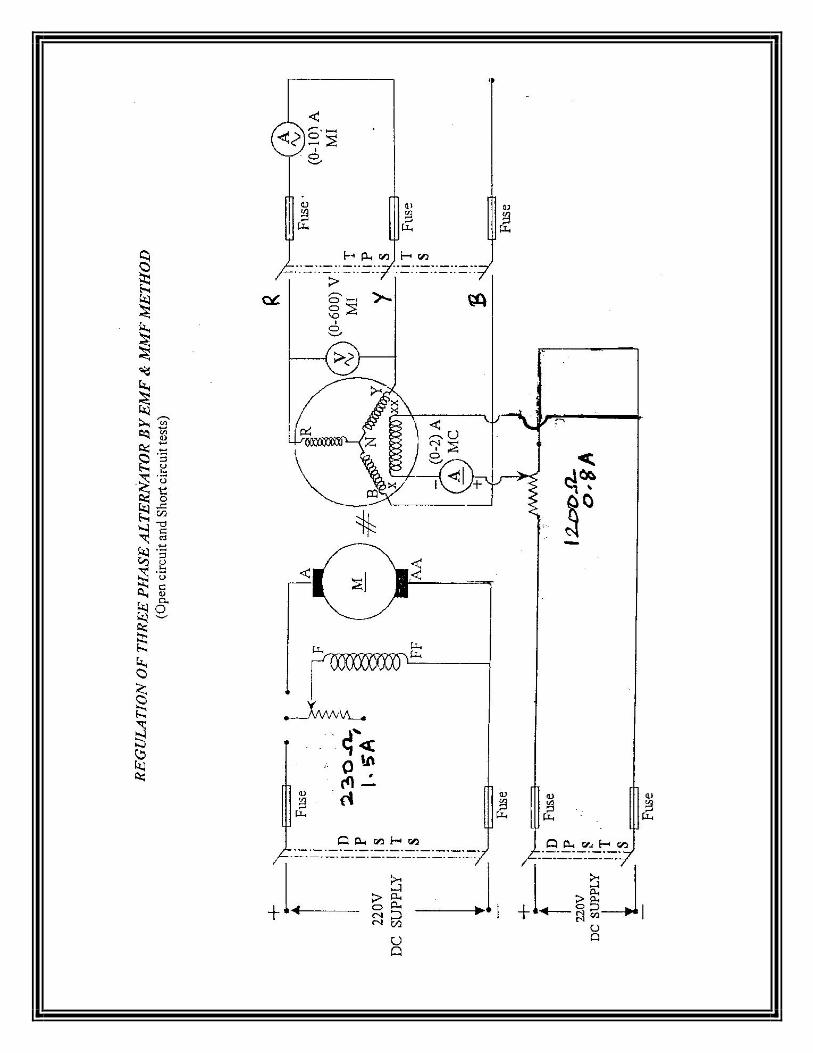
REGULATION OF 3–PHASE ALTERNATOR BY EMF AND MMF METHODS
AIM:
To predetermine the regulation of 3-phase alternator by EMF and MMF methods and also
draw the vector diagrams.
APPARATURS REQUIRED:
SL.NO Name of the Apparatus Type Range Quantity
1 Ammeter MC 0 – 1/2 A 1
2 Ammeter MI 0 – 5/10 A 1
3 Voltmeter MC 0 – 10 V 1
4 Voltmeter MI 0 – 600 V 1
5 Rheostat Wire wound 250 Ω, 1.5 A 1
6 Rheostat Wire wound 1200Ω, 0.8 A 1
7 Tachometer Digital --- 1
8 TPST knife switch -- -- 1
THEORY:
The regulation of a 3-phase alternator may be predetermined by conducting the Open
Circuit (OC) and the Sort Circuit (SC) tests. The methods employed for determination of
regulation are EMF or synchronous impedance method, MMF or Ampere Turns method and the
ZPF or Potier triangle method. In this experiment, the EMF and MMF methods are used. The OC
and SC graphs are plotted from the two tests. The synchronous impedance is found from the OC
test. The regulation is then determined at different power factors by calculations using vector
diagrams. The EMF method is also called pessimistic method as the value of regulation obtained
is much more than the actual value. The MMF method is also called optimistic method as the
value of regulation obtained is much less than the actual value. In the MMF method the armature
leakage reactance is treated as an additional armature reaction. In both methods the OC and SC
test data are utilized.
PRECAUTIONS:
(i) The motor field rheostat should be kept in the minimum resistance position.
(ii) The alternator field potential divider should be kept in the minimum voltage
position.
(iii) Initially all switches are in open position.
PROCEDURE: (FOR BOTH EMF AND MMF METHODS)
1. Note down the name plate details of the motor and alternator.
2. Connections are made as per the circuit diagram.
3. Switch ON the supply by closing the DPST switch.

4. Using the Three point starter, start the motor to run at the synchronous speed by adjusting
the motor field rheostat.
5. Conduct Open Circuit test by varying the potential divider for various values of field
current and tabulate the corresponding Open Circuit Voltage readings.
6. Conduct Short Circuit test by closing the TPST switch and adjust the potential divider to
set the rated armature current and tabulate the corresponding field current.
7. The Stator resistance per phase is determined by connecting any one phase stator winding
of the alternator as per the circuit diagram using MC voltmeter and ammeter of suitable
ranges.
PROCEDURE TO DRAW GRAPH FOR EMF METHOD:
1. Draw the Open Circuit Characteristic curve (Generated Voltage per phase VS Field
current).
2. Draw the Short Circuit Characteristics curve (Short circuit current VS Field current)
3. From the graph find the open circuit voltage per phase (E1 (ph) for the rated short
circuit current (Isc).
4. By using respective formulae find the Zs, Xs, Eo and percentage regulation.
PROCEDURE TO DRAW GRAPH FOR MMF METHOD:
1. Draw the Open Circuit Characteristic curve (Generated Voltage per phase VS Field
current).
2. Draw the Short Circuit Characteristics curve (Short circuit current VS Field current)
3. Draw the line OL to represent
FORMULAE:
1. Armature Resistance Ra = Ω
2. Synchronous Impedance Zs = O.C. voltage
S.C. current
3. Synchronous Reactance Xs = √ Zs2 – Ra2
4. Open circuit voltage for lagging p.f = √(VcosΦ + IaRa)2 + (VsinΦ + IaXs)2
5. Open circuit voltage for leading p.f. = √(VcosΦ + IaRa)2 + (VsinΦ – IaXs)2
6. Open circuit voltage for unity p.f = √(V + IaRa)2 + ( IaXs)2
7. Percentage regulation = Eo – V x 100
V
RESULT:
Thus the regulation of 3-phase alternator has been predetermined by the EMF and MMF
methods.

VIVA QUESTIONS:
1. What is meant by voltage regulation?
2. What is meant by Synchronous Impedance?
3. What is OC test ?
4. What is SC test?
5. What is meant by mmf or field ampere turns?

REGULATION OF 3-PHASE ALTERNATOR BY EMF AND MMF METHODS
TABULAR COLUMNS
OPEN CIRCUIT TEST:
S.No.
Field Current (If) Open Circuit Line
Voltage (VoL)
Open circuit Phase
Voltage (Voph)
Amps Volts Volts
SHORT CIRCUIT TEST:
S.No.
Field Current (If)
Short Circuit Current (120%
to 150% of rated current)
(ISC)
Amps Amps

REGULATION OF 3-PHASE ALTERNATOR BY EMF AND MMF METHODS
TABULAR COLUMNS
EMF METHOD:
SL.NO.
Power
factor
Eph (V) % Regulation
Lag
Lead
Lag
Lead
MMF METHOD:
SL.NO.
P.F
Vph
(V)
If1
(A)
If2
(A)
Ifr
(A)
Eph (V) % Regulation
Lag Lead Lag Lead Lag Lead


EXP.NO. 2 DATE:
REGULATION OF 3-PHASE ALTERNATOR BY POTIER AND ASA METHODS
AIM:
To predetermine the regulation of three phase alternator by Potier and ASA methods and
also to draw the vector diagrams.
APPARATURS REQUIRED:
SL.NO Name of the Apparatus Type Range Quantity 1 Ammeter MC 0 – 1/2 A 1
2 Ammeter MI 0 – 5/10 A 1
3 Voltmeter MC 0 – 10 V 1
4 Voltmeter MI 0 – 600 V 1
5 Rheostat Wire wound 250 Ω, 1.5 A 1
6 Rheostat Wire wound 1200Ω, 0.8 A 1
7 Tachometer Digital --- 1
8 TPST knife switch -- -- 1
FORMULAE USED:
Percentage regulation = Eo – Vrated x 100 (For both POTIER & ASA methods)
Vrated
PRECAUTION:
(i) The motor field rheostat should be kept in the minimum resistance position.
(ii) The Alternator field potential divider should be in the position of minimum
potential.
(iii) Initially all switches are in open position.
PROCEDURE FOR BOTH POTIER AND ASA METHODS:
1. Note down the complete nameplate details of motor and alternator.
2. Connections are made as per the circuit diagram.
3. Switch on the supply by closing the DPST main switch.
4. Using the Three point starter, start the motor to run at the synchronous speed by varying
the motor field rheostat.
5. Conduct an Open Circuit Test by varying the Potential Divider for various values of
Field current and tabulate the corresponding Open circuit voltage readings.
6. Conduct a Short Circuit Test by closing the TPST knife switch and adjust the potential
divider the set the rated Armature current, tabulate the corresponding Field current.
7. Conduct a ZPF test by adjusting the potential divider for full load current passing through
either an inductive or capacitive load with zero power and tabulate the readings.
8. Conduct a Stator Resistance Test by giving connection as per the circuit diagram and
tabulate the voltage and Current readings for various resistive loads.
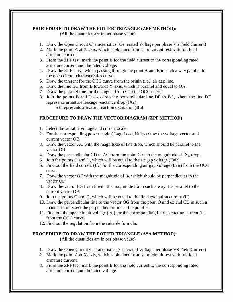
PROCEDURE TO DRAW THE POTIER TRIANGLE (ZPF METHOD):
(All the quantities are in per phase value)
1. Draw the Open Circuit Characteristics (Generated Voltage per phase VS Field Current)
2. Mark the point A at X-axis, which is obtained from short circuit test with full load
armature current.
3. From the ZPF test, mark the point B for the field current to the corresponding rated
armature current and the rated voltage.
4. Draw the ZPF curve which passing through the point A and B in such a way parallel to
the open circuit characteristics curve.
5. Draw the tangent for the OCC curve from the origin (i.e.) air gap line.
6. Draw the line BC from B towards Y-axis, which is parallel and equal to OA.
7. Draw the parallel line for the tangent from C to the OCC curve.
8. Join the points B and D also drop the perpendicular line DE to BC, where the line DE
represents armature leakage reactance drop (IXL)
BE represents armature reaction excitation (Ifa).
PROCEDURE TO DRAW THE VECTOR DIAGRAM (ZPF METHOD)
1. Select the suitable voltage and current scale.
2. For the corresponding power angle ( Lag, Lead, Unity) draw the voltage vector and
current vector OB.
3. Draw the vector AC with the magnitude of IRa drop, which should be parallel to the
vector OB.
4. Draw the perpendicular CD to AC from the point C with the magnitude of IXL drop.
5. Join the points O and D, which will be equal to the air gap voltage (Eair).
6. Find out the field current (Ifc) for the corresponding air gap voltage (Eair) from the OCC
curve.
7. Draw the vector OF with the magnitude of Ifc which should be perpendicular to the
vector OD.
8. Draw the vector FG from F with the magnitude Ifa in such a way it is parallel to the
current vector OB.
9. Join the points O and G, which will be equal to the field excitation current (If).
10. Draw the perpendicular line to the vector OG from the point O and extend CD in such a
manner to intersect the perpendicular line at the point H.
11. Find out the open circuit voltage (Eo) for the corresponding field excitation current (If)
from the OCC curve.
12. Find out the regulation from the suitable formula.
PROCEDURE TO DRAW THE POTIER TRIANGLE (ASA METHOD):
(All the quantities are in per phase value)
1. Draw the Open Circuit Characteristics (Generated Voltage per phase VS Field Current)
2. Mark the point A at X-axis, which is obtained from short circuit test with full load
armature current.
3. From the ZPF test, mark the point B for the field current to the corresponding rated
armature current and the rated voltage.

4. Draw the ZPF curve which passing through the point A and B in such a way parallel to
the open circuit characteristics curve.
5. Draw the tangent for the OCC curve from the origin (i.e.) air gap line.
6. Draw the line BC from B towards Y-axis, which is parallel and equal to OA.
7. Draw the parallel line for the tangent from C to the OCC curve.
8. Join the points B and D also drop the perpendicular line DE to BC, where the line DE
represents armature leakage reactance drop (IXL)
BE represents armature reaction excitation (Ifa).
9. Extend the line BC towards the Y-axis up to the point O’. The same line intersects the air
gap line at point G.
10. Mark the point I in Y-axis with the magnitude of Eair and draw the line from I towards
OCC curve which should be parallel to X-axis. Let this line cut the air gap line at point H
and the OCC curve at point F.
11. Mention the length O’G, HF and OA.
PROCEDURE TO DRAW THE VECTOR DIAGRAM (ASA METHOD)
(To find the field Excitation current If)
1. Draw the vector with the magnitude O’G.
2. From G draw a vector with the magnitude of GH (OA) in such a way to make an angle of
(90 ± Φ) from the line O’G [ (90 + Φ) for lagging power factor and (90 – Φ) for leading
power factor]
3. Join the points O’ and, H also extend the vector O’F with the magnitude HF. Where O’F
is the field excitation current (If).
4. Find out the open circuit voltage (Eo) for the corresponding field excitation current (If)
from the OCC curve.
5. Find out the regulation from the suitable formula.
RESULT:
Thus the regulation of 3-phase alternator has been predetermined by the Potier and ASA
methods.
VIVA QUESTIONS:
1. What is meant by ZPF Test?
2. What is Potier reactance? How is it determined by Potier triangle?
3. What is meant by armature reaction reactance?
4. What is the significance of the ASA modification of MMF method?
5. What is air gap line in Potier method?


EXP.NO. 3 DATE:
REGULATION OF 3-PHASE SAILENT POLE ALTERNATOR
BY SLIP TEST
AIM:
To conduct a slip test on 3-Ф alternator and pre-determine the regulation through vector
diagram.
APPARATUS REQUIRED:
S.no Name of
Apparatus
Range Type Quantity
1 Ammeter (0-5)A MI 1
(0-1)A MC 1
2 Voltmeter (0-150)V MI 1
(0-5)V MC 1
3 Rheostat 250 Ω /1.5A 1
4 Tachometer Digital 1
5 TPST Switch 1
6 Connecting
Wires
As reqd.
FUSE RATING:
(a)For Motor- 125% of rated current
= 125% of 17A=21.25A=25A
(b)For Alternator- 125% of rated current
=125% of 4A= 5A
THEORY:
In a salient pole alternator, the reactance of magnetic circuit along is along its quad stator axis.
The alternator is driven by auxiliary prime mover at a speed slightly less than the synchronous
speed under these conditions. The armature current is when the armature current mmf is in line
with the field poles. The reactance by the magnetic field current is minimum. The ratio of
maximum voltage to minimum current gives the direct axis impedance and the ratio of minimum
voltage to maximum current gives the armature axis impedance.
PRECAUTIONS:
1. The motor field rheostat should be kept in minimum.
2. The direction of the rotation due to prime mover and the alternator on the motor should
be the same.
3. Initially all the switches are kept open.

PROCEDURE:
1. Note down the name plate details of motor and alternator.
2. Connections are made as per the circuit diagram.
3. Give the supply by closing the DPST switch.
4. Using the three point starter, start the motor to run at the synchronous speed by varying
the motor field rheostat at the same time check whether the alternator field has been
opened or not.
5. Apply 20% to 30% of the rated voltage to the armature of the alternator by adjusting the
autotransformer.
6. To obtain the slip and the maximum oscillation of pointers the speed is reduced slightly
lesser than the synchronous speed.
7. Maximum current, minimum current, maximum voltage and minimum voltage are noted.
8. Find out the direct and quadrature axis impedances.
PROCEDURE TO DRAW THE VECTOR DIAGRAM:
1. Draw the line OA that represents the rated voltage V.
2. Draw the line OB vector to represent the rated current I, which makes an angle Φ (it may
lag/lead/in phase) with the voltage.
3. Draw the line AC vector to represent IRa drop, which is parallel to OB vector.
4. Draw the perpendicular line CD to the line AC (IRa drop) that represents IXq drop.
5. Draw the line from the origin through the point D, which represents the no load voltage
(Eo).
6. Draw the pole axis through origin, which should be perpendicular to vector OD.
7. Draw a perpendicular line to the pole axis from the same point E which should pass
through the point B [where vector OE represents Direct Axis Current (Id) and Vector EB
represents Quadrature Axis Current (Iq)].
8. Find out the reactive voltage drops IdXd and IqXq.
9. Draw a parallel line (ie perpendicular to Id) to OD vector from the point C, with the
magnitude of the drop IdXd (Line CF).
10. Draw a parallel line (ie perpendicular to Iq) to OE vector from the point F, with the
magnitude of the drop IqXq (Line FG).
11. Let the point at where the IqXq drop meets the OD line be G. here the vector OG
represents the no load voltage (Eo).
12. Find out the voltage regulation by using the suitable formula.
FORMULAE USED:
1. Rac=1.6Rac Ω
2. Zd = Vmax/Imin Ω
3. Zq = Vmin/Imax Ω
4. Xd = √Zd2 – Rd2 Ω
5. Xq = √Zq2 – Rd2 Ω

6. Id = Ia sinФ amps
7. Iq = Ia cos Ф amps
8. %Reg = (Eo-V/V)*100
Where,
Zd = direct axis impedance in Ω
Zq = quadrate axis impedance in Ω
Xd = direct axis reactance in Ω
Xq = quadrate axis reactance in Ω
Id = direct axis current in amps
Ia = quadrate axis current in amps
GRAPH:
Power Factor VS % regulation.
RESULT:
Thus the pre-determination of regulation of 3-phase alternator by vector diagram was
obtained.
VIVA QUESTIONS:
1. What is the purpose of slip test on 3 phase alternator?
2. What is meant by direct axis reactance?
3. What is meant by quadrature axis reactance?
4. How is the regulation of alternator predetermined by slip test?
5. What is the difference between salient pole alternator and cylindrical rotor type
alternator?

SLIP TEST ON 3-PHASE ALTERNATOR
TABULAR COLUMNS
(i) To find the Direct Axis and Quadrature axis impedances:
S.NO Vmax Vmin Imax Imin
1
2
(ii) To predetermine % Regulation:
S.NO
Power Factor
% Regulation
Lagging
Leading
Unity
1
0.2
--
2
0.4
--
3
0.6
--
4
0.8
--
5
1.0


EXP.NO. 4 DATE:
V AND INVERTED V CURVE OF THREE PHASE
SYNCHRONOUS MOTOR
AIM
To draw the V and inverted V curves of a 3 phase Synchronous Motor.
NAME PLATE DETAILS:
3ǾSYNCHRONOUS MOTOR DC EXCITATION
FUSE RATING: 125% of rated current (full load current)
For DC excitation:
For synchronous motor:]
APPARATUS REQUIRED:
S.No Name of the
apparatus
Type range Quantity
1
2.
3.
4.
5.
Ammeter
Voltmeter
Ammeter
Rheostat
Wattmeter
MI
MI
MC
UPF
(0-5)A
(0-600)V
(0-2)A
200Ω,15A
600V,5A
2
2
1
1
2

PRECAUTION: (1) The Potential barrier should be in maximum position.
(2) The motor should be started without load .
(3) Initially TPST switch is in open position.
PROCEDURE: (1) Note down the name plate details of the motor.
(2) Connections are made as pr the circuit diagram..
(3) Close the TPST switch.
(4) By adjustingthe autotransformer from the minimum position to the maximum
position the rated supply is given to motor. The motor starts as an induction motor.
(5) In order to give the excitation to the field for making it to run as the synchronous
motor, close the DPST switch.
(6) By varying the field rheostat note down the excitation current, armature current and
the power factor for various values of excitation.
(7) The same process has to be repeatedfor loaded condition.
(8) Later the motor is switched offand the graph is drawn.
GRAPH: The graph is drawn for-
(1) Armature current Vs Excitation current.
(2) Power factor Vs Excitation current.
RESULT:
The V-curves and inverted V-curves of the 4 phase synchronous motor have been drawn.


EXP.NO.5 A DATE:
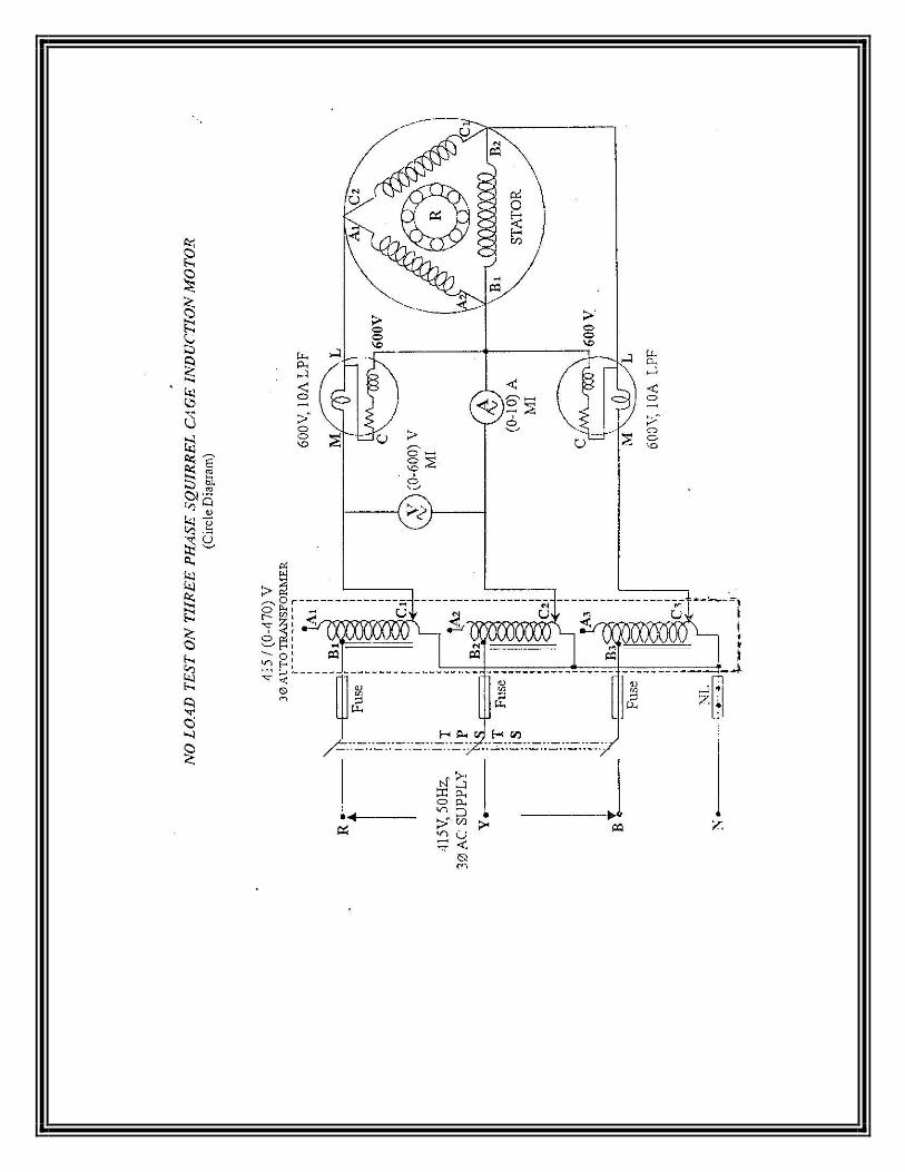
LOAD TEST ON 3-PHASE SQUIRREL CAGE INDUCTION MOTOR
AIM: To draw the performance characteristics of 3-phase squirrel cage induction motor by
conducting load test.
APPARATUS REQUIRED:
S.No Name of
apparatus
Range Type Qty.
1. Ammeter (0-5)A MI 1
2. Voltmeter (0-600)V MI 1
3. Wattmeter (600V,5A) UPF 2
4. Tachometer Digital 1
5. 3-Ф
autotransformer
1
FUSE RATING;
125% of 4.8A=6A=10A
THEORY:
A 3-phase induction motor consists of stator and rotor with the other associated parts. In the
stator, a 3-phase winding is provided. The windings of the three phase are displaced in space by
120º.A 3-phase current is fed to the 3-phase winding. These windings produce a resultant
magnetic flux and it rotates in space like a solid magnetic poles being rotated magnetically.
PRECAUTIONS:
1. TPST switch is kept open initially.
2. Autotransformer is kept at min. voltage position.
3. There must be no load when starting the load.
PROCEDURE:
1. Connections are given as per circuit diagram.
2.3-Ф induction motor is started with DOL starter.
3. If the pointer of one of the wattmeter readings reverses, interchange the current coil terminals
and take the reading as negative.
3. The no load readings are taken.
4. The motor is loaded step by step till we get the rated current and the readings of the voltmeter,
ammeter, wattmeter’s, spring balance are noted.

FORMULAE USED:
1) % slip= (Ns-N/Ns)*100
2) Input Power = (W1+W2)watts
3) Output Power = 2∏NT/60 watts
4) Torque = 9.81*(S1-S2)*R N-m
5) % efficiency = (o/p power/i/p power)* 100
GRAPHS:
1) Output Power vs Efficiency
2) Output Power vs Torque
3) Output Power vs Speed
4) Output Power vs %s
RESULT
Thus the performance characteristics of a 3-Ф squirrel cage induction motor by conducting load
test has been drawn.


EXP.NO. 5 B DATE:
LOAD TEST ON 3-PHASE SLIP RING INDUCTION MOTOR
AIM:
To conduct a direct load test on a 3-phase slip ring induction motor and to draw the
performance characteristics.
APPARATUS REQUIRED:
S.NO NAME OF
APPARATUS
RANGE TYPE QTY.
1 Ammeter (0-10)A
MI 1
2 Voltmeter (0-600)V MI 1
3 Wattmeter (600V,10A) UPF 2
4 Tachometer Digital 1
FUSE RATING-
FOR- STATOR- 125% 0f 7.5A = 10A
FOR ROTOR – 125% of 11A = 15A
THEORY:
Slip ring induction motor is also called as phase wound motor. The motor is wound for as many
poles as the no. of stator poles and always wound 3-Ф even while the stator is wound two-phase.
The other three windings are brought out and connected to three insulated slip-rings mounted on
the shaft with brushes resting on them. These three brushes are further externally connected to a
three phase star connected rheostat. This makes possible the introduction of an additional
resistance in the rotor circuit during starting period for increasing starting torque of the motor.
PRECAUTIONS:
1. TPST switch is kept open initially.
2. The external resistance in the rotor circuit should be kept at max. value.
PROCEDURE:
1. Connections are given as per circuit diagram.
2. After observing precautions motor is started on no load.
3. As speed increases, the external resistance is gradually cut out.
4. The no-load readings are taken.
5. If the pointer in one of the wattmeter reverses, interchange the current coil terminals and
take the reading as negative.
6. The meter readings are then noted for various load conditions.

FORMULAE USED:
1. Torque= (S1-S2)*9.81*100 N-m
2. O/P Power= 2πNT/60 watts
3. I /P Power = (W1+W2) watts
4. η % = (o/p power/ i/p power)*100
5. %s = (Ns-N)/Ns*100
GRAPHS:
1. O/P power vs Speed
2. O/P power vs Torque
3. O/P Power vs η
4. O/P Power vs slip
5. Torque vs Speed
6. Torque vs Slip
RESULT:
The load test on 3-Ф slip ring induction motor was conducted and the performance
characteristics curves were plotted.


EXP.NO.6 DATE:
NO LOAD AND BLOCKED ROTOR TEST ON 3- PHASE
INDUCTION MOTOR
AIM: To conduct the no load & blocked rotor test on 3- phase induction motor
& to draw the equivalent circuit of 3- phase squirrel cage induction motor.
APPARATUS REQUIRED:
FUSE RATING :-
125/100 * 7.5 A ≈ 10A
THEORY :-
A 3-phase induction motor consists of stator, rotor & other associated parts. In the stator
,a 3- phase winding (provided) are displaced in space by 120. A3- phase current is fed to the
winding so that a resultant rotating magnetic flux is generated. The rotor starts rotating due to the
induction effect produced due the relative velocity between the rotor
Winding & the rotating flux.
PRECAUTIONS :-
NO LOAD TEST –
(1). Initially TPST switch is kept open.
(2). Autotransformer must be kept at minimum potential position.
(3). The machine must be started at no load.
S.NO NAME OF
APPARATUS
RANGE TYPE QTY
1. Voltmeter (0-600)V
(0-150)V
MI
MI
01
01
2. Ammeter (0-10)A MI 01
3. Wattmeter (600V,5A)
(150V,10A)
UPF
LPF
01
01
4. Connecting wire As required


BLOCKED ROTOR TEST
(1). Initially the TPST switch is kept open.
(2). Autotransformer must be kept at minimum potential position.
(3). The machine should be started on full load.
PROCEDURE
NO LOAD TEST
(1). Connections are given as per the circuit diagram.
(2). Precautions are observed and motor is started on the no load.
(3). Autotransformer is varied to have rated voltage applied.
(4). The meter readings are then tabulated.
BLOCKED ROTOR TEST :-
(1). Connections are given as per circuit diagram.
(2). Precautions are observed and motor is started on full load or blocked rotor position.
(3). Autotransformer is varied to have rated current flowing in motor.
(4). The meter readings are then tabulated.
FORMULA USED-
FOR NO LOAD TEST-
Wsc = √3 Vo IoCOSФ watts
Iw = Io cosФ amps
Ro= V0/ Iw Ω
Xo= Vo/Iu Ω
FOR BLOCKED ROTOR TEST-
Wsc =3I2*Ro watts
Ro1 = Wsc/3(Isc)2 Ω
Zo1 = Vsc/Isc Ω
Xo1 = √Zo1^2-Ro1^2 Ω
RESULT:-
Thus the no load and blocked rotor test on 3-Фsquirrel cage induction motor is performed
and the equivalent circuit of 3-phase squirrel cage induction motor has been drawn.

TABULAR COLUMNS
NO LOAD TEST:
S.No Voltage
Voc
Volts
Current
Ioc
Amps
Wattmeter
readings (W1)
W1 x
mf1
Wattmeter
readings (W2)
W2 x
mf2
Observed
Actual
Watts
Observed
Actual
Watts
1
Voc= open circuit voltage
Ioc = open circuit current
BLOCKED ROTOR TEST:
S.No. Voltage
Vsc
Volts
Current
Isc
Amps
Wattmeter
readings(W1)
W1 x
mf1
Wattmeter
readings(W2)
W2 x
mf2
Observed
Actual
Watts
observed Actual
Watts
1.
Vsc = short circuit voltage
Isc = short circuit current


EXP.NO. 7 DATE:
SEPARATION OF NO LOAD LOSSES OF THREE PHASE INDUCTION
MOTOR
AIM:
To separate the no load losses of a 3 phase squirrel cage induction motor as iron losses
and mechanical losses.
NAME PLATE DETAILS:
3Ø induction motor Auto Transformer
FUSE RATING:
No load :10% of rated current (full load current).
APPARATUS REQUIRED:
S.No Name of the apparatus Type Range Quantity
1.
2.
3.
4.
5.
Ammeter
Voltmeter
Wattmeter
3-Ф Auto Transformer
Rheostat
MI
MC
MI
MC
LPF
(0-10)A
(0-1)A
(0-600)V
(0-5)V
600V,5A
(415/0-
470)V
1200Ω/0.8A
1
1
1
1
2
1
1
PRECAUTIONS:
(1) The autotransformer should be kept in minimum voltage position.
(2) The motor should not be loaded throughout the experiment.

PROCEDURE:
(1) Connections should be made as per the circuit diagram.
(2) by giving three phase supply , start the motor.
(3)vary the autotransformer till rated speed is attainsd and note the input power, voltage and
current.
(4)repeat the same procedure for and tabulate the reading.
(5)find the stator copper loss and constant loss by respective formulas.
(6)draw the suitable graph to find the mechanical losses.
(7)obtain the core los by separating the mechanical loss fom constant losses.
GRAPH:
The graph drawn between constant losses(watts) and input voltage(volts).
MODEL CALCULATIONS:
1. Input power(W) =(W1+W2)in watts
2. Stator copper loss =3I2Rs in watts
3. Constant loss/phase(Wc)= (W-3I2Rs)/3 in watts
4 Core loss/phase (Wi)= (constant loss/phase)-mechanical loss
RESULT:
Thus the no load losses of 3-phase squirrel cage induction motor was separated as core
losses and mechanical losses.


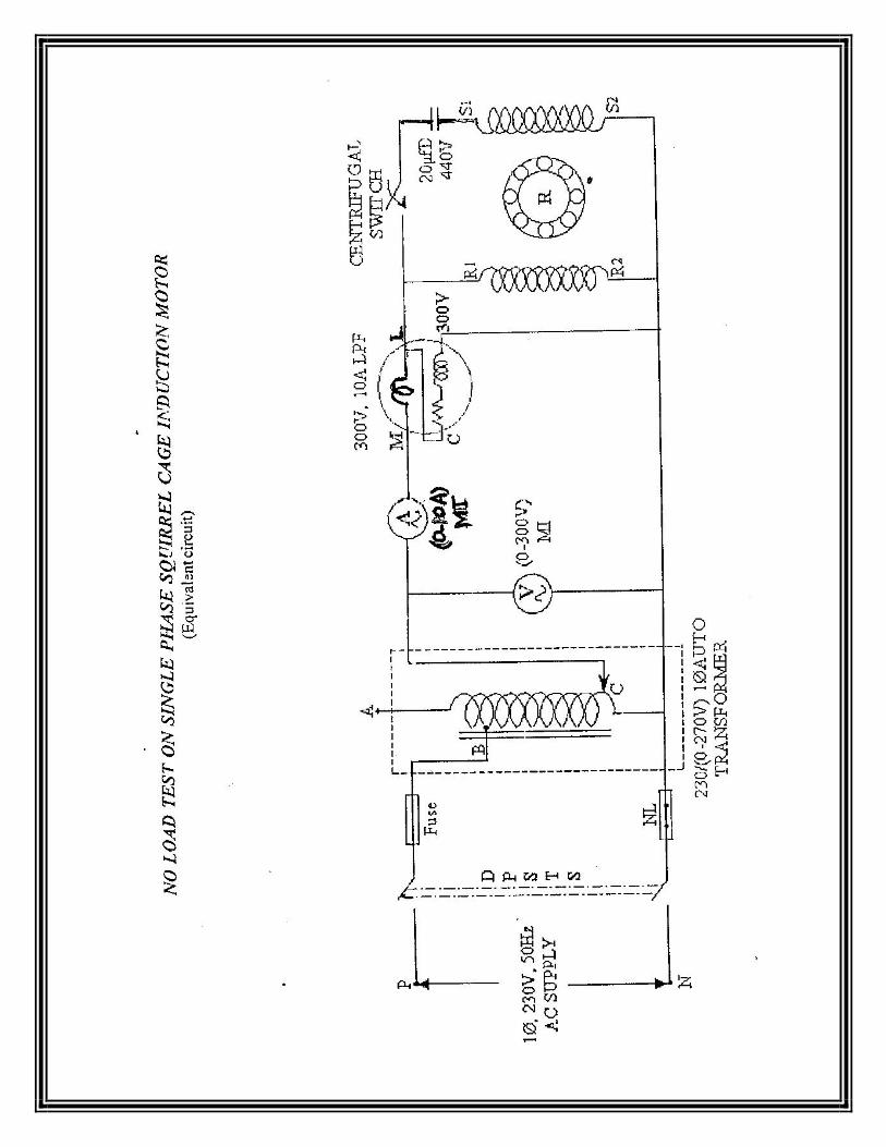
EXP.NO. 8 DATE:
LOAD TEST ON SINGLE PHASE INDUCTION MOTOR
AIM: To determine the performance characteristic of a given single phase capacitor start
induction motor by conducting load test.
APPARATUS REQUIRED:
SL. NO APPARATUS RANGE TYPE QUANTITY
1 Voltmeter (0-300)V MI 1
2 Ammeter (0-10)A MI 1
3 Wattmeter 300 V, 10A UPF 1
4 Tachometer 1
5 Connecting wires As required
FUSE RATING:
Fuse rating = 125% of rated current = 125/100 * 7.5
≈ 10A
THEORY:
The single phase induction motor is more or less a polyphase induction motor. The only
difference is that is given supply in single phase. This motor connect and motor function
without any initial start the motor having some part which is called starter and rotor.
These
are two types of starting a 1 phase induction motor namely capacitor-start and other is
split-
phase. These motors are widely used in domestic purpose.
PRECAUTION:
1) Before switching on the supply the variac is kept in minimum position.
2) Initially these should be on no load while starting the motor.
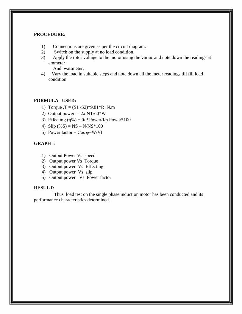
PROCEDURE:
1) Connections are given as per the circuit diagram.
2) Switch on the supply at no load condition.
3) Apply the rotor voltage to the motor using the variac and note down the readings at
ammeter
And wattmeter.
4) Vary the load in suitable steps and note down all the meter readings till fill load
condition.
FORMULA USED:
1) Torque ,T = (S1~S2)*9.81*R N.m
2) Output power = 2π NT/60*W
3) Effecting (η%) = 0/P Power/I/p Power*100
4) Slip (%S) = NS – N/NS*100
5) Power factor = Cos φ=W/VI
GRAPH :
1) Output Power Vs speed
2) Output power Vs Torque
3) Output power Vs Effecting
4) Output power Vs slip
5) Output power Vs Power factor
RESULT:
Thus load test on the single phase induction motor has been conducted and its
performance characteristics determined.

TABULAR COLUMN
m.f =
Sl.No. VL
V
IL
A
Speed(N)
RPM
S1
Kg
S2
Kg
S1 ~ S2
Kg
Torque
N-m
Wattmeter Reading Output
Power
W
Efficiency
η
%
PF= cosΦ
Observed Actual
1
2
3
4
5
6
7
8
MODEL CALCULATION:
Input power = W x m.f = Watts % slip = (Ns – N)/Ns x 100 pf= cosΦ = W/VLIL Output power = 2лNT/ 60 Watts
Torque T= (S1~S2)*9.81*R N-m, where R is the radius of the brake drum in metre
Output power
Efficiency η = x 100
Input power

EXP.NO. 9 DATE:
NO LOAD AND BLOCKED ROTOR TEST ON SINGLE PHASE INDUCTION MOTOR
AIM:
To draw the performance characteristics of a single phase induction motor by conducting
the no-load and blocked rotor test.
APPARATUS REQUIRED:
S.No Name of
Apparatus
Range Type Qty.
1 Voltmeter (0-300)V MI 1
(0-150)V MI 1
2 Ammeter (0-10)A MI 1
(0-2)A MI 1
3 Wattmeter (330V,10A) UPF 1
(300V,5A) LPF 1
4 Connecting
wires
As reqd.
FUSE RATING:
125% of 7.6A=10A
THEORY:
A 1-Ф induction motor consists of stator,rotor and other associated parts.In the rotor of a single
phase winding is provided.The windings of a 1- Ф winding(provided) are displaced in space by
120º.A single phase current is fed to the windings so that a resultant rotating magnetic flux is
generated.The rotor starts rotating due to the induction effect produced due to the relative
velocity between the rotor winding and the rotating flux.
PRECAUTIONS:
NO LOAD TEST:
Initially TPST Switch is kept open.
Autotransformer is kept at minimum potential position.
The machines must be started on no load.


BLOCKED ROTOR TEST:
Initially the TPST Switch is kept open.
Autotransformer is kept at minimum potential position.
The machine must be started at full load (blocked rotor).
PROCEDURE:
NO LOAD TEST:
1. Connections are given as per the circuit diagram.
2. Precautions are observed and the motor is started at no load.
3. Autotransformer is varied to have a rated voltage applied.
BLOCKED ROTOR TEST:
1. Connections are given as per the circuit diagram.
2. Precautions are observed and motor is started on full load or blocked rotor position.
3. Autotransformer is varied to have rated current flowing in motor.
4. Meter readings are the noted.
Reff = 1.5*Rdc
FORMULAE-
NO LOAD TEST-
cos Ф = Wo/VoIo
Iw = Io cosФ
Im = Io sin Ф
Ro = Vo/Iw
Xo = Vo/Im
BLOCKED ROTOR TEST-
Zsc = Vsc/Isc Ω
Rsc = Wsc/Isc2 Ω
Xsc = √(Zsc2 – Rsc2) Ω

RESULT-
Thus the no load and blocked rotor test on the single phase induction motor has been conducted
and the equivalent circuit has been drawn.
TABULATION
NO LOAD TEST
S.No. Vo(volts) Io(amps) Wo(watts)
m.f Observed Acual
BLOCKED ROTOR TEST
S.No. Vsc(volts) Isc(amps) Wsc(watts)
m.f Observed Actual

Negative sequence
Zero sequence

EXP.NO. 2 DATE:
MEASUREMENT OF NEGATIVE SEQUENCE AND ZERO SEQUENCE IMPEDANCE
OF ALTERNATOR
AIM: Determination of negative sequence and zero sequence Impedance of a synchronous generator.
APPARATUS REQUIRED:
SL.NO Name of the Apparatus Type Range Quantity
1 Ammeter MI (0-5)A 1
2 Ammeter MC (0-2)A 1
3 Voltmeter MC (0-300)V 1
4 Voltmeter MC (0-75)V 1
5 Dimmer Stat 1 phase 230V 1
6 Wattmeter 150V,5A 1
7 Tachometer Digital --- 1
THEORY:
When a synchronous generator is carrying an unbalanced load its operation may be
analyzed by symmetrical components. In a synchronous machine the sequence current produce
an armature reaction which is stationary with respect to reactance and is stationary with respect
to field poles. The component currents therefore encounter exactly same as that by a balanced
load as discussed. The negative sequence is produced and armature reaction which rotates around
armature at synchronous speed in direction to that of field poles and therefore rotates part the
field poles at synchronous speed. Inducing current in the field damper winding and rotor iron.
The impendence encountered by the negative sequence is called the – ve sequence impedance of
the generator. The zero sequence current produce flux in each phase but their combined armature
reaction at the air gap is zero. The impedance encountered by their currents is therefore different
from that encountered by + ve and –ve sequence components and is called zero sequence
impedance of generator.
Negative sequence:
The –ve sequence impedance may be found by applying balanced –ve sequence voltage
to the armature terminals. While the machine is drive by the prime mover at its rated
synchronous speed with the field winding short circuited. The ratio of v/ph and Ia/ph gives –ve
sequence Z/ph. The reading of the wattmeter gives I2 R losses. This loss /ph divided by Iph

required gives the –ve sequence R/ph from the impedance and reactance/ph. –ve sequence can be
calculated. Another method of measuring –ve sequence reactance is found to be connect the arm
terminals. The machine is driven at synchronous speed and field current adjusted until rated
current flows in the phases shorted through armature and current coil of wattmeter respectively
Zero sequence:
The sequence impedance may be determined by the connecting the armature windings of
the three phase in series and then connecting them to the single phase source of power. If the
machine is driven at synchronous speed with field winding shorted, then ZO=V/3I practically the
same results will be obtained with rotor stationary.
If windings are connected in parallel, then
PROCEDURE
A. For Negative Sequence (1) Make connection as shown in circuit diagram. (2) Run DC motor with synchronous speed.
(3) Keeping the speed constant, vary the excitation and measure the voltmeter,
ammeter and wattmeter reading.
(4) Take 3-4 readings for different excitation.
(5) The excitation should not be increased beyond the rated capacity of
synchronous machine i.e. 4.2 A

B. For Zero Sequence
(1)Make connection as shown in circuit diagram. (2)Set the dimmer stat output to zero volts and switch on the supply.
(3) Gradually increase dimmer stat output and note the ammeter reading for
Suitable voltage applied.
(4) Repeat reading for suitable voltage applied.
(5) It should be kept in mind that the ammeter reading should not exceed the rated
current
Capacity of the machine i.e. 4.2 A. RESULT:
The negative sequence reactance and zero sequence reactance of an alternator was determined.

TABULATION
Negative sequence Impedance
Voltmeter(V) Wattmeter (W) Ammeter (A)
Zero sequence Impedance
Voltmeter(V) Wattmeter (W) Ammeter (A)


