Embed Size (px)
Citation preview

Tacho LycosCDR Presentation
January 16, 2018

Overview
• Vehicle Design• Dimensions• Performance
• Recovery
• Avionics
• Payload Design• Integration• Rover
• Subscale Flight Summary
• Compliance Plan
2

Vehicle DesignFinal Dimensions
Section Breakdown
Design Features
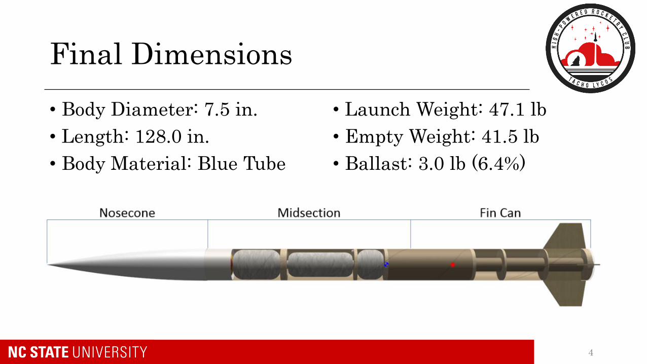
Final Dimensions
• Body Diameter: 7.5 in.
• Length: 128.0 in.
• Body Material: Blue Tube
• Launch Weight: 47.1 lb
• Empty Weight: 41.5 lb
• Ballast: 3.0 lb (6.4%)
4

Nosecone
• Shape: 5:1 Ogive• 7.5 in. base, 37.5 in. length
• Material: ABS Plastic
• Main parachute compartment
5

Midsection
• 7.5 in. OD
• Blue Tube 2.0
• Payload/Avionics bays
• Main/Drogue compartments
• Removable upper section and access hatch
6

Fin Can
• 7.5 in. OD, Blue Tube 2.0
• Drogue compartment
• 4 mounted fins
• 1.25 in. engine block
• Rail buttons
7

Fins
• 2 layers of 0.125 in. birch
• Alignment tabs for fabrication
8

PerformanceFinal Motor Choice
Aerodynamics
Simulated Flight Profiles
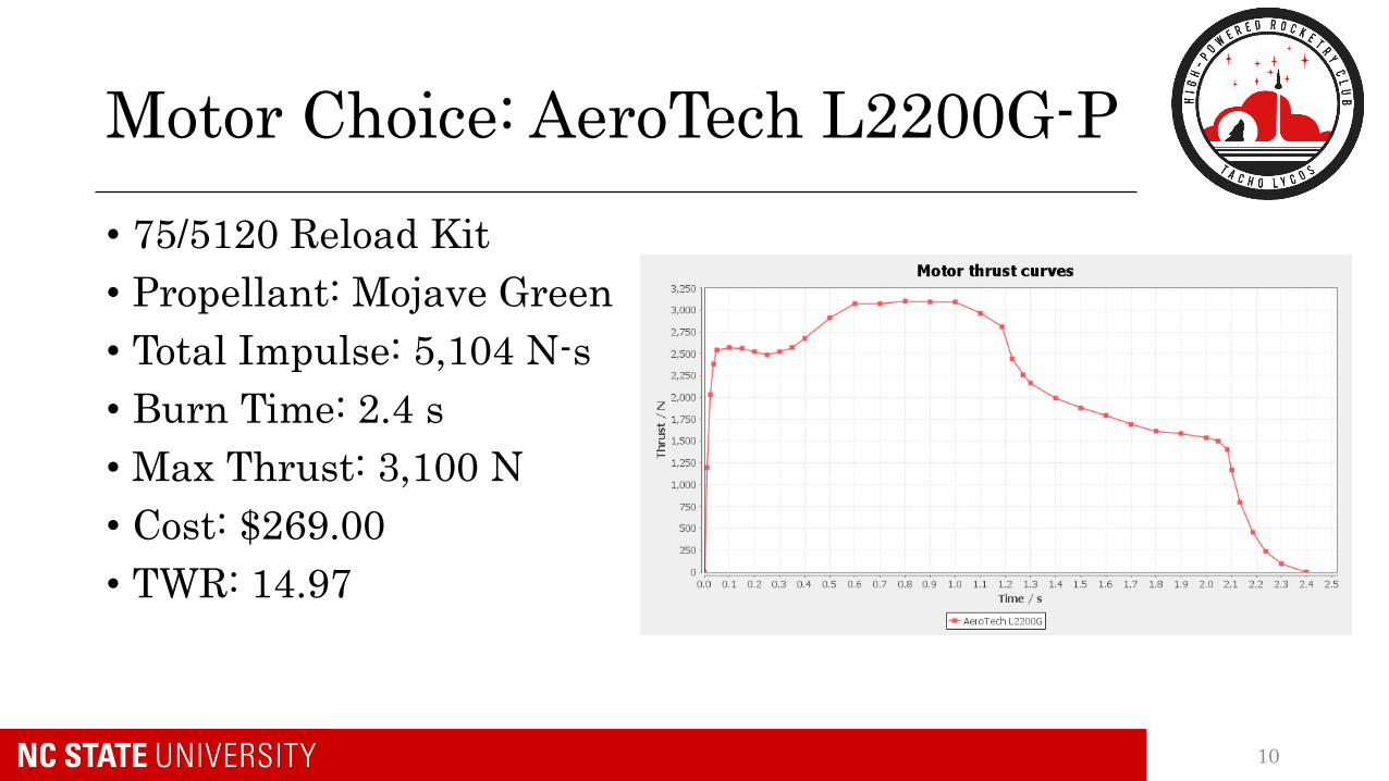
Motor Choice: AeroTech L2200G-P
• 75/5120 Reload Kit
• Propellant: Mojave Green
• Total Impulse: 5,104 N-s
• Burn Time: 2.4 s
• Max Thrust: 3,100 N
• Cost: $269.00
• TWR: 14.97
10

Aerodynamics
• XCP = 94.9 in.
• XCG = 79.5 in.
• Stability Margin = 2.05 cal
• CD = 0.42• Wood filler to fill surface grooves
• Rounded leading/trailing edges
• Spray paint to finish
11

OpenRocket Flight Simulations
• Location: Huntsville, AL
• Windspeed: 10 mph
• Launch Rail: 8 ft (1515)
• Angle: 5° from vertical
• Apogee: 5,351 ft AGL
• Max Velocity: 703 ft/s• M = 0.63
• Rail Exit = 73.3 ft/s
• Max Acceleration: 458 ft/s2
12

RecoveryRecovery Devices
Recovery Harnesses
Wind Drift Predictions
Avionics

Recovery Devices
• Drogue Parachute – Apogee• 24 in. Fruity Chutes Std. Elliptical• Vdescent = 93.2 ft/s
• Low Altitude Recovery Device – 1,000 ft AGL• Reduce structural forces on rover latch• Same shock cord as drogue• Jolly Logic Chute Release• 60 in. Fruity Chutes Iris Ultra Std. • Vdescent = 28.5 ft/s
• Main Parachute – 700 ft AGL• 120 in. Fruity Chutes Iris Ultra Std. • 38.2 lb empty weight• Vdescent = 13.85 ft/s
14

Recovery Harness
• (2) 480 in. x ½ in. tubular kevlar• 2200 lb strength
• (2) Nomex blankets (Drogue and LARD)
• (1) Deployment bag (Main Parachute)
15
480” 480 in.
120” 180”180”

Wind Drift
• OpenRocket simulations at varying windspeeds
16

Wind Drift
17
• Hand Calculations:• Higher than OpenRocket
• Assumes one direction and
constant wind
• Does not include lag from
deployment bag
• Confident that results will be
more like OpenRocket

Avionics
• 2 altimeters to deploy parachutes• StratoLoggerCF
• Entacore AIM
• Jolly Logic Chute Release for LARD
• Each altimeter will be independently powered to add redundancy
• Each altimeter will be armed by a key switch mounted to rocket exterior
18
Drogue Black Powder Charge at Apogee
Redundant Drogue Black Powder Charge at
Apogee + 1 second
StratoLoggerCF Altimeter
Main Black Powder Charge at 700 ft.
Redundant Main Black Powder Charge at 700
ft. + 1 second
Duracell 9 V Battery
Key Switch
Key Switch
Drogue Parachute release
Main Parachute release
Low Altitude Recovery Device release
Jolly Logic Chute Release activates at
1000 ft.
Electrical activation
Physical activation
Battery
Altimeter
Black Powder Charge
Parachute
Entacore AIM USB 3 Altimeter
Duracell 9 V Battery

Avionics Sled
StratoLogger (red), Entacore (green)
Batteries (brown)
• Altimeters can be viewed face-upfrom open hatch
• Made of 1/8 in. plywood
• Total Weight = 0.96 lb• Max Weight = 2.0 lb
19

GPS Tracker
• BigRedBee BRB900
• 250 MW, 900 Mhz frequency
• 6 mile range, 2.5hr memory
• Internal battery
• Attached to nosecone bulkhead beside U-bolt
• Transmits lat/longcoordinates to receiver
20

Payload Integration
Design
Fabrication
Electronics

Structure
Payload Tube• 5.25” x .125” wall acrylic tube - 14” long• In between two Lazy Susan Bearings
• Will prevent the payload from moving with the rocket during flight
• Allow the rover to self right during descent for landing
• A .25” thickbirch disk will be attached inside the aft end for Lazy Susan
• The entire structure will be between two bulkheads
22

Lazy Susan Bearings (LSB)
• The aft payload will be a VXB 120mm Lazy Susan Aluminum Bearing Turntable bearings• OD: 120mm (4.7”), ID: 60mm (2.36”),
thickness: 9.5mm (.37”)• Contains two concentric bearing rings• Attaches to the the bulkhead and tube
disk via four opposing countersink screws
• The forward LSB will be a 3D printed custom designed bearing carrier and schedule 40 PVC contacting piece• Considering manufacturing the piece out
of aluminum for strength increase and friction decrease
23
3D Printed Bearing Carrier
Ball BearingPVC Connector
Foam Spacer

Rover Support
• The rover will rest on a .25” 3D printed platform • fits the curve of the interior of the tube.• Rests 1.25” below the central axis of the
tube• the front face fills the entirety of the
tube for an inch
• The rover is supported from above by two extended runners• Attached to the interior face of the tube
directly above the treads• Will be 3D printed and adhered using
epoxy resin
24

Electronic Latch & Receiver
• Rover will secured laterally using a Southco R4-EM-63-161 Electronic Rotary Latch
• The latch with hold the rover by the bolt on the rover
• It is controlled via a remote controller• The Latch will be controlled with a
EA-R02-202 receiver• Controlled via key fob up to 60 ft away• The latch and receiver are powered by
a single A23 battery
25

Payload Plug
• The payload will be sealed by a plug
• Made out of two .25” birch plywood disks
• Outside edge with be wrapped in a rubber gasket to create seal
• Possesses a U-bolt that the main shock chord loops around
• Will be pulled during the main parachute deployment
26

Deployable Rover
Design
Fabrication
Electronics

Rover Goals
• Custom rover deployed from internal structure
• Remote activation
• Autonomously move 5 ft laterally in any direction
• Deploy a set of foldable solar panels after reaching its final destination
28

Remote Activation and Autonomy
29
MSP430 RN-42 Bluetooth Module

Motion
30
Front wheel with servo

Solar Sail
31

Subscale Summary
Launch Conditions
Flight Profile
Results

Launch Day Conditions
• November 18, 2017 in Bayboro, NC
• 10 knot (11.5 mph) steady winds• Gusting up to 20 knots (23.0 mph)
• Experimental payload built at field
33

Subscale Flight
• Apogee = 2,093 ft AGL• Predicted = 2,006 ft AGL
• Max Velocity = 387 ft/s• Predicted = 386 ft/s
• Impact Velocity = 8 ft/s• Predicted = 12 ft/s
• Total Flight Time = 181.7 s• Predicted = 169.3 s
• Accurate predictions
34

Subscale Recovery
• Main parachute set to 800 ft AGL
• Both parachutes deployed at apogee• Main primary charge wired to drogue redundant altimeter
• Impact on full-scale design:• Color-coded, labelled wiring to be installed
• Multiple people in charge of checking wiring
• Train more team members to recognize errors
• Additional practice assembly sessions to train
• Re-designed avionics sled, altimeters more accessible
35

Subscale Payload Results
• Payload damaged and waterlogged from landing
• Onboard computer failed torecord roll rate during flight
• Minimal damage to payloadstructure after landing
• After bearing fractured to allow ball bearings to escape
36

ComplianceExperiments
Tests

Test Plans and Compliance
Launch Vehicle Testing:
• Black powder ground testing
• Rover bay plug seal testing
• Electronics interference testing
• GPS location tracking test
Payload Testing:
• Rover capabilities testing• Determining physical limits of the design
38

39
Questions?