Embed Size (px)
Citation preview

�
Table of Contents
Introduction ........................................................................... 2
Distribution Systems .............................................................. 4
Switchboard Definition ........................................................... 9
Switchboard Construction .................................................... �2
Service Entrance Equipment ................................................. �8
Service Section .................................................................... 20
Switchboard Grounding ....................................................... 23
Ground Fault Protection ....................................................... 26
Service Section Main Disconnect Devices .............................. 30
Distribution Section.............................................................. 35
Switchboard Ratings ............................................................ 37
SB�, SB2, and SB3 Switchboards ........................................... 40
Rear Connected Switchboards .............................................. 44
Integrated Power System Switchboards ................................ 45
Generator Ready Switchboards ............................................. 47
Solar Ready Switchboards ..................................................... 5�
Super Blue Pennant Switchboards ........................................ 52
Multi-Metering Switchboards ............................................... 54
Speciality Service Entrance Switchboards.............................. 56
Things to Consider ............................................................... 57
Review Answers ................................................................... 59
Final Exam ........................................................................... 60

2
Introduction
Welcome to another course in the STEP series, Siemens Technical Education Program, designed to prepare our distributors to sell Siemens Industry, Inc. products more effectively. This course covers Basics of Switchboards and related products.
Upon completion of Basics of Switchboards you should be able to:
• Explain the role of switchboards in a distribution system
• Define a switchboard according to the National Electrical Code®
• Identify the main parts of a switchboard
• Identify various ways power can be brought into a switchboard service section
• Explain the difference between hot and cold sequence in relation to current transformers
• Identify the types of main and distribution devices available for Siemens switchboards
• Identify the various models of Siemens switchboards
This knowledge will help you better understand customer applications. In addition, you will be better able to describe products to customers and determine important differences between products. You should complete Basics of Electricity and Basics of Circuit Breakers before attempting Basics of Switchboards. An understanding of many of the concepts covered in these courses is required for Basics of Switchboards.
After you have completed this course, if you wish to determine how well you have retained the information covered, you can complete a final exam online as described later in this course. If you pass the exam, you will be given the opportunity to print a certificate of completion from your computer.

3
Siemens is a trademark of Siemens AG. Product names mentioned may be trademarks or registered trademarks of their respective companies. Specifications are subject to change without notice.
NFPA70®, National Electrical Code®, and NEC® are registered trademarks of the National Fire Protection Association, Quincy, MA 02�69.
NEMA®is a registered trademark and service mark of the National Electrical Manufacturers Association, Rosslyn, VA 22209.
Underwriters Laboratories Inc.® and UL® are registered trademarks of Underwriters Laboratories Inc., Northbrook, IL 60062-2096.
Other trademarks are the property of their respective owners.

4
Distribution Systems
Power distribution systems are used in every residential, commercial, and industrial building to safely control the distribution of electrical power throughout the facility.
Residential Power Most of us are familiar with the power distribution systemDistribution found in the average home. Power purchased from a utility
company enters the house through a metering device. The power is then distributed from a load center to various branch circuits for lighting, appliances, and electrical outlets.
Main Circuit Breaker
Load Center
Branch Circuit Breakers
Meter

5
Commercial and Industrial Power distribution systems used in commercial and industrialPower Distribution facilities are more complex than those used in single-family
homes and must be capable of handling higher levels of current and voltage. Although some small facilities usually do not require switchboards, medium and large facilities commonly use switchboards to safely distribute power to transformers, panelboards, control equipment, and, ultimately, to system loads.
Good power distribution systems don’t just happen, however. Careful engineering is required to ensure that a power distribution system is capable of safely and efficiently supplying adequate electric service to existing loads and has expansion capacity for possible future loads.
Transformer
Padmount Transformer
PanelboardMotorStarter
Switchboard
Switchgear
Distribution of Current The role of a switchboard is to divide the main current provided to the switchboard into smaller currents for further distribution and to provide switching, current protection, and metering for these various currents. Although this applies to all switchboards, the voltages and currents involved vary with the size of the application.

6
Small Office Building A small office building, for example, might require �20 volts forExample interior lighting and receptacles and 208 volts for heating, air
conditioning, and exterior lighting. In this example, the utility company supplies 208/�20 volt, three-phase, four-wire service. The main incoming line is divided into four feeders. The two outer feeders supply power directly to the 208 volt heating and air conditioning units. The two inner feeders are divided into a number of branch circuits. One set of branch circuits supplies power to exterior lighting. The second set of branch circuits supplies power to interior lighting and receptacles.
Utility Supply208/120 Volts
3-Phase, 4-Wire
Feeders
Branches
208 VoltElectric Heating
208 VoltParking Lot Lighting
120 VoltInterior Lighting
and Receptacles
208 VoltAir Conditioning
The electric utility uses a step-down transformer to supply power to a facility. There are a number of ways the secondary of the utility transformer could be configured. In the following example, the utility supplies power from a transformer with a wye-connected secondary. The secondary winding of the transformer produces 208/�20 VAC. Single-phase �20 VAC is available between any phase wire and neutral. Single-phase 208 VAC is available between any two phases. All three phases are connected to any equipment requiring three-phase power.
120 Volts208 Volts
120 Volts
120 Volts
208 Volts
208 Volts
A
B
C

7
Incoming power is metered by the utility company. In this example, power is supplied to the building through a main service disconnect. A switchboard divides the power into four feeders for distribution throughout the building.
Utility Supply 208/120 Volts, 3-Phase, 4-Wire
Meter and Socket
WallMain ServiceDisconnect
Distribution Switchboard208/120 Volts, 3-Phase, 4-Wire
Non-FusibleDisconnectSwitch
Motor Starter
208 Volt, 3-WireRooftop
Air ConditioningUnit
120 Volt, 2-WireLighting andRecepticles
LightingPanelboard
LightingPanelboard
208 VoltParking Lot
Lighting
208 Volt ElectricHeating Unit
Non-FusibleDisconnectSwitch
Medium-sized Industrial The next example is representative of the distribution systemPlant Example for a medium-sized industrial plant. In this example, the
incoming power is provided by a 480/277 VAC, three-phase, four-wire system.
Three feeders are used. The first feeder is used for various types of power equipment. The second feeder supplies a group of 480 VAC motors. The third feeder is used for �20 volt lighting and receptacles.
Utility Supply480/277 Volts
3-Phase, 4-Wire
Feeders
BranchesBranches
PowerEquipment
480 VoltMotors
120 VoltLighting andReceptacles

8
In this application, the secondary winding of the utility transformer provides the 480/277 VAC needed to power the system.
277 Volts480 Volts
277 Volts
277 Volts
480 Volts
480 Volts
A
B
C
The power from the utility company is metered and enters the plant through a distribution switchboard. The switchboard incorporates a main circuit breaker and circuit breakers for each of the three feeders.
The feeder on the left powers a distribution switchboard, which, in turn, feeds a panelboard and a 480 volt, three-phase motor. The middle feeder powers another switchboard which divides the power into three, three-phase, three-wire circuits. Each circuit feeds a busway run to 480 volt motors. The feeder on the right supplies 208/�20 volt power to panelboards connected to lighting and receptacles.
Meter and Socket Utility Supply, 480/277 Volts, 3-Phase, 4-Wire
Ground Fault ProtectionMain Power DistributionSwitchboard with Service Mains
DistributionTransformer
480 - 208/120 Volts3-Phase, 3-Wire
DistributionSwitchboard
DistributionSwitchboard
DistributionSwitchboard
DisconnectSwitch
MotorStarter
PowerPanelboard
480 Volt3-Phase
Motor
480 Volt, 3-Phase, 3-WireBusways for Motor Loads
East
North
West
Lighting and ReceptaclePanelboards for Manufacturing
and Offices
480/277 Volt, 3-Phase, 4-Wire Feeder480 Volt, 3-Phase, 3-Wire Feeders480 Volt, 3-Phase, 3-Wire Circuits208/120 Volt, 3-Phase, 4-Wire Circuits
1234
1 2
3
4
GFP
M
M

9
Switchboard Definition
Definition The National Electrical Code® (NEC®) defines a switchboard as a large single panel, frame, or assembly of panels on which are mounted, on the face, back, or both, switches, overcurrent and other protection devices, buses, and usually instruments.
Enclosed Devices As this definition indicates, switchboards enclose various devices. For example, the following illustration shows two switchboard sections, an incoming or service section and a distribution section that provides power to feeder and branch circuits. Circuit breakers mounted in these sections provide overcurrent protection. Some switchboards use fusible switches instead of circuit breakers
Service Section
Distribution Section
Circuit Breaker

�0
Buses As the NEC® definition states, switchboards include buses, which are metal bars mounted inside the switchboard to conduct power to the switchboard’s devices.
s
Buses
Instrumentation The NEC® definition of a switchboard also indicates that the switchboard may have instrumentation. This instrumentation often includes one or more meters designed to accept signals from sensors and other equipment and display representative values for power monitoring and management.
North
WestEastM
9510
13.8 kV Utility Supply
ServiceSwitchboard
Power QualityMeter
Transformer 480/277 VAC3-phase, 4 wire
Transformer 208/120 VAC3-phase, 3-wire
DistributionSwitchboard
Panelboards
DistributionSwitchboards
480 VAC Busway for Motor Loads
SafetySwitch
Panelboard
MotorStarter
480/277 VAC3-phase, 4-wire
480 VAC3-phase, 3-wire
PowerMeters
PowerMeter

��
May Be Accessible from Another characteristic of a switchboard identified in the NEC®Rear definition is that it may be installed away from a wall to provide
access to the rear of the switchboard. Keep in mind, however, that this is not a requirement of all switchboards.
Switchboard Standards Switchboards are built according to standards set by Underwriters Laboratory (UL 891) and the National Electrical Manufacturers Association (NEMA PB2). Basic requirements for switchboards are also covered in National Electrical Code®
Article 408.
Review 1�. ________ systems are used in every residential,
commercial, and industrial building to safely control the distribution of electrical power throughout the facility.
2. The phase-to-neutral voltage of a wye-connected transformer with a phase-to-phase voltage of 208 volts is ________ volts.
3. The phase-to-neutral voltage of a wye-connected transformer with a phase-to-phase voltage of 480 volts is ________ volts.
4. Switchboards can include which of the following items?
a. Overcurrent protective devices b. Buses c. Power meters c. All the above
5. According to the National Electrical Code® definition, switchboards can be accessible from the ________.

�2
Switchboard Construction
There are multiple elements that make up a switchboard. Included in the list of elements are a frame, buses, overcurrent protective devices, service metering, and outer covers.
Frame The frame of the switchboard houses and supports the other components. The standard Siemens switchboard frame is 90 inches high and 32 or 38 inches wide. An optional height of 70 inches with widths of 32, 38, or 46 inches is also available. Siemens switchboards have a depth measurement ranging from 20 to 58 inches.
Height
WidthDepth
Frame
Buses A bus is a conductor or set of conductors that serves as a common connection for two or more circuits. Switchboard buses are constructed from metal bus bars which are mounted inside the switchboard to conduct power to various devices.
�3
NEMA Phase Arrangement Bus bars are required to have phases in sequence so that an installer can have the same fixed-phase arrangement in each termination point in any switchboard. This is established by NEMA (National Electrical Manufacturers Association). If a non-NEMA phase sequence is used, it must be marked on the switchboard. Unless otherwise marked, it is assumed that bus bars are arranged according to NEMA. The following diagram illustrates accepted NEMA phase arrangements.
Vertical(Left-to-Right)
As Viewed fromthe Front
Horizontal(Top-to-Bottom)
A B C
A
B
C
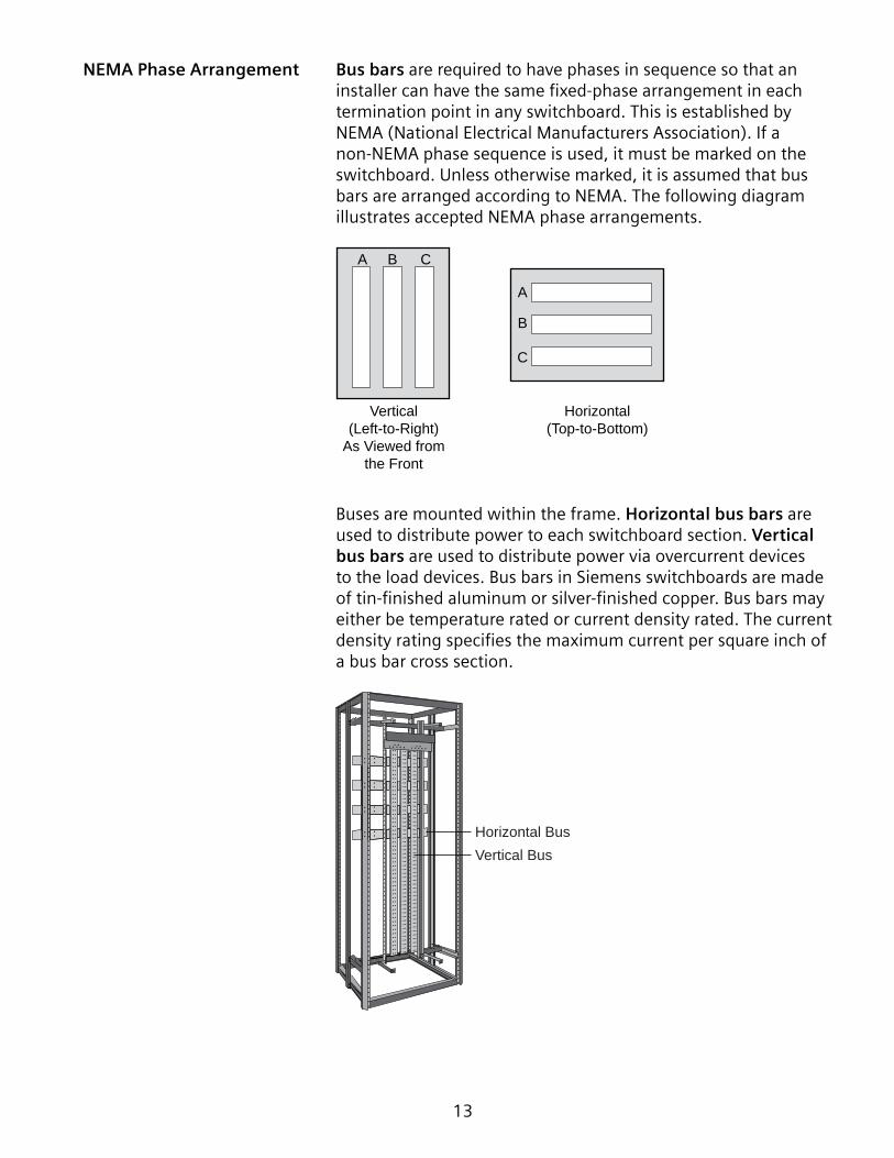
Buses are mounted within the frame. Horizontal bus bars are used to distribute power to each switchboard section. Vertical bus bars are used to distribute power via overcurrent devices to the load devices. Bus bars in Siemens switchboards are made of tin-finished aluminum or silver-finished copper. Bus bars may either be temperature rated or current density rated. The current density rating specifies the maximum current per square inch of a bus bar cross section.
Vertical BusHorizontal Bus

�4
The following rear view drawing of a switchboard illustrates vertical and horizontal bus bar connections. The vertical phase bus bars appear to be in reverse order because they are viewed from the rear, but are in the proper NEMA order as viewed from the front.
A bus connector makes a mechanical and electrical connection between a vertical bus bar and its corresponding horizontal bus bar. In this drawing the connector can be clearly seen on the neutral bus. Compression lugs provided on this switchboard accept properly sized incoming power cables.
C B A NCompression Lugs
For Incoming Power
Vertical Bus
C
B
A
N
Horizontal Bus
Connector
Splice Plate Connection
Rear View
�5
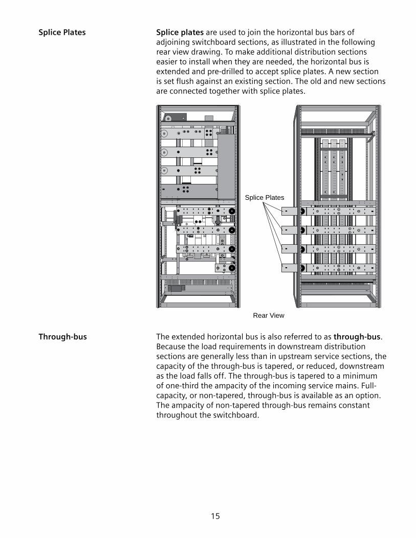
Splice Plates Splice plates are used to join the horizontal bus bars of adjoining switchboard sections, as illustrated in the following rear view drawing. To make additional distribution sections easier to install when they are needed, the horizontal bus is extended and pre-drilled to accept splice plates. A new section is set flush against an existing section. The old and new sections are connected together with splice plates.
Splice Plates
Rear View
Through-bus The extended horizontal bus is also referred to as through-bus. Because the load requirements in downstream distribution sections are generally less than in upstream service sections, the capacity of the through-bus is tapered, or reduced, downstream as the load falls off. The through-bus is tapered to a minimum of one-third the ampacity of the incoming service mains. Full-capacity, or non-tapered, through-bus is available as an option. The ampacity of non-tapered through-bus remains constant throughout the switchboard.
�6
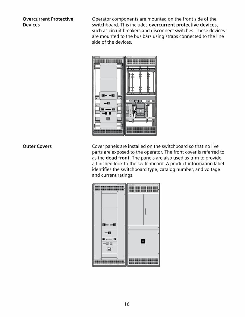
Overcurrent Protective Operator components are mounted on the front side of the Devices switchboard. This includes overcurrent protective devices,
such as circuit breakers and disconnect switches. These devices are mounted to the bus bars using straps connected to the line side of the devices.
Outer Covers Cover panels are installed on the switchboard so that no live parts are exposed to the operator. The front cover is referred to as the dead front. The panels are also used as trim to provide a finished look to the switchboard. A product information label identifies the switchboard type, catalog number, and voltage and current ratings.

�7
Pictorial Diagram Simplified drawings, such as one-line, block, or pictorial diagrams are often used to show the circuits associated with a power distribution system. For example, the following pictorial diagram shows a two section switchboard.
Incoming Supply
Main Circuit Breaker
Vertical Bus
Horizontal Bus
Branches
Switchboard Feeders
Review 2 �. The standard height of a Siemens switchboard frame is
________ inches.
2. A ________ is a conductor or set of conductors that serves as a common connection for two or more circuits.
3. As viewed from the front of a switchboard, the NEMA bus bar phase sequence from left to right is ________.
4. Siemens switchboard bus bars are made of tin-finished ________ or silver-finished ________.
5. ________ are used to join the horizontal bus bars of adjoining switchboard sections.

�8
Service Entrance Equipment
Switchboards are often used as service entrance equipment for a building. Service entrance equipment is the equipment through which power enters the building. For example, the following drawing shows a switchboard service section connected to a utility power source. This service section provides power to a switchboard distribution section and, subsequently, to downstream equipment.
Service Section
Distribution Section
Service EntranceEquipment
Power FromUtility Company
Service Entrance
Downstream Equipment
ExteriorWall
Switchboards used as service entrance equipment must be approved and labeled as such. Siemens switchboards are factory labeled as suitable for use as service entrance equipment (SUSE) when specified for service entrance application.
Six Disconnect Rule Service entrance conductors must have a readily accessible means of being disconnected from the power supply. NEC®
Article 230.7� specifies that for each set of service entrance conductors no more than six switches or circuit breakers shall be used to disconnect and isolate the service from all other equipment.
In the following example, a single main circuit breaker can disconnect power from all equipment being supplied by the service. In this example, there can be as many feeder and branch disconnect devices as needed.

�9
Utility Supply
Utility Power Meter M
Service Conductors
MainDisconnect
BranchDisconnects
To Various Loads
In another example, a switchboard may be equipped with up to six circuit breakers to disconnect power from all equipment being supplied by the service.
Utility Supply
Utility Power Meter M
Service Conductors
Main DisconnectNot Needed
BranchDisconnects
To Various Loads
It is important to note that the six disconnect rule refers to the number of disconnects and not the number of poles. For example, in the following illustration there are �8 poles but only six circuit breakers. Three poles are mechanically linked together to form one disconnect device. This configuration allows the service to be disconnected with no more than six operations of the hand and complies with the six disconnect rule.
1
2
3
4
5
6
A B C

20
Service Section
A typical switchboard installation consists of a service section, also referred to as the main section, and one or more distribution sections. The service section can be fed directly from the utility transformer. In addition to the main disconnect, the service section usually contains utility or customer metering provisions.
Service Section
Distribution Section
Service Entrance Methods Several options are available to bring power into the switchboard service section. For example, cable can be brought into the switchboard from the top or the bottom.

2�
Cable can be brought into the top of the switchboard through conduit. If the cable has a large diameter and more room is needed, a pull box, available in �0” to 30” heights, can be added. In addition, a bus duct entrance can be provide when a busway connection is needed.
Cable andConduit Entrance
Pull BoxAdded
Bus DuctEntrance
10" to 30"
Cable may enter through a conduit to a disconnect that is fed from the bottom. If the disconnect is top-fed, a pull section can be added to the side of the service section to pass cable to the top of the switchboard. Depending on the cable bending space, cable can be connected directly to the lugs or to a cross bus. A cross bus brings the bus connections to the pull section eliminating the need to bend cables.
ServiceSection
PullSection
ServiceSection
PullSection
ServiceSection
PullSectionAdded
Bottom-fedMain Disconnect
Pull SectionWith Cross Bus
Underground Conduit
Cross Bus
Main Disconnect
22
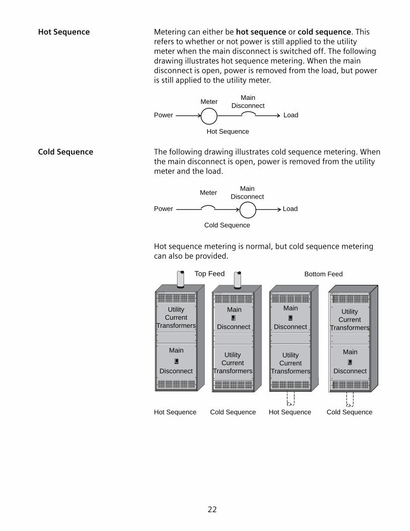
Hot Sequence Metering can either be hot sequence or cold sequence. This refers to whether or not power is still applied to the utility meter when the main disconnect is switched off. The following drawing illustrates hot sequence metering. When the main disconnect is open, power is removed from the load, but power is still applied to the utility meter.
MainDisconnect
Load
Meter
Power
Hot Sequence
Cold Sequence The following drawing illustrates cold sequence metering. When the main disconnect is open, power is removed from the utility meter and the load.
MainDisconnect
Load
Meter
Power
Cold Sequence
Hot sequence metering is normal, but cold sequence metering can also be provided.
Top Feed Bottom Feed
Hot Sequence Cold Sequence Hot Sequence Cold Sequence
UtilityCurrent
Transformers
Main
Disconnect
UtilityCurrent
Transformers
Main
Disconnect
Main
Disconnect
UtilityCurrent
Transformers
Main
Disconnect
UtilityCurrent
Transformers

23
Switchboard Grounding
Grounding is an important aspect of any electrical system and must be considered carefully. Any object that is electrically connected to the earth is grounded, but not all ground connections are intentional. A ground connection can occur accidentally as a result of faulty equipment or wiring. Proper intentional grounding, however, is essential to the safe operation of electrical equipment.
There are two primary reasons for intentionally grounding electrical equipment:
• Grounding reduces the shock hazard by minimizing the voltage differential between parts of a system.
• Grounding provides a low impedance path to ground for fault current. The lower the impedance, the greater the current in the event of a fault. The greater the current, the faster the overcurrent device opens and removes power from the load.
N
Ground

24
Service Entrance Grounding In the following drawing, a switchboard is used as service entrance equipment and is connected to a three-phase, four-wire service. Note that the neutral is grounded at the service entrance. This is accomplished by connecting the neutral to a ground bus bar. The ground bus bar is connected to the frame of the switchboard and the frame is connected to ground. The neutral disconnect link is left in place to supply a ground connection to downstream loads. This link is provided so that downstream equipment can be disconnected from ground for testing and troubleshooting.
Utility Power Source
Service EntranceSwitchboard
Ground Bus Bar
A B C N Neutral toGround
Connection
NeutralDisconnect
Link
To Downstream LoadsEarth
Ground

25
Downstream Equipment The neutral is only connected to ground at the service entrance. When downstream equipment is used, the neutral is isolated in that equipment.
The following illustration shows a service entrance switchboard connected to a downstream section. The neutral of the downstream section is connected to ground through the ground bus bar of the service entrance switchboard. The neutral is not connected to ground in the downstream switchboard.
Notice also that the downstream switchboard does not have a neutral disconnect link. Neutral disconnect links are not required in switchboards used as non-service entrance equipment. Any downstream section fed from the second switchboard would also be connected to ground through the service entrance switchboard.
Ground Bus Bar
A B C N
To Downstream Loads
A B C NUtility Power Source
Service EntranceSwitchboard
EarthGround

26
Ground Fault Protection
A ground fault is a condition in which electrical current takes an undesirable path to ground. Typically the current flows from a conductor to an adjacent grounded conductor or grounded surface. The most common type of ground fault is an arcing ground fault. In such cases, current often takes a high resistance path to ground and may flow intermittently or for a short duration. As a result, a ground fault often will not trip a circuit breaker unless it has been designed to sense ground faults. None the less, ground faults can still be dangerous.
In some applications, such as for selected locations in a residence, ground fault protection is required for life protection. In many commercial or industrial applications, ground fault protection is required to protect equipment.
According to the NEC®, ground-fault protection of equipment must be provided for solidly grounded wye electrical services of more than �50 volts to ground but not exceeding 600 volts phase-to-phase for each service disconnecting means rated �000 amperes or more.
When ground fault protection is incorporated into a switchboard, it is often through use of circuit breakers with ground fault protection.

27
Direct Method One way a ground fault protector works is with a sensor around a ground conductor, normally the neutral-to-ground strap. This
is referred to as the direct method. When a line-to-ground fault occurs, current flows through the sensor. When the fault current reaches the threshold setting of the ground-fault protection equipment, a shunt trip opens the circuit breaker.
Circuit Breaker withShunt Trip Option
Relay
A
B
C
N
Neutral
Ground Fault Sensor
Service Equipment(1000 Amps or More)
To Load
Zero Sequencing Method Another way a ground fault protector works is with a sensor installed around all the circuit conductors, including the neutral
on four-wire systems. This is referred to as the zero sequencing method. When there is no ground fault, the sum of all the currents detected by the sensor is zero. When a ground fault occurs, it causes a current imbalance that is sensed by the protection equipment. When the fault current reaches the threshold setting of the ground-fault protection equipment, a shunt trip opens the circuit breaker.
Circuit Breaker withShunt Trip Option
To Load
A
NB
C
Service Equipment(100 Amps or More)Ground Fault Sensor
Relay

28
Residual Method Another approach is the residual method, which requires separate sensors to monitor current on all three phases, and the neutral on a four-wire system. With this system, when there is no ground fault, the vectorial sum of the currents is zero. If a ground fault is sensed, however, a shunt trip opens the circuit breaker.
A
NB
C
Circuit Breaker withShunt Trip Option
Service Equipment(100 Amps or More)Ground Fault Sensor
Relay
To Load
Ground Fault Ground fault protection is often provided through an optionalProtection Devices feature of a circuit breaker. In such cases, the circuit breaker is
frequently equipped with fixed or variable settings for ground fault pick-up (Ig), the level of ground fault current required to trip the breaker, and ground fault time delay (tg), the interval of time the breaker will remain closed after a ground fault is sensed. These settings are useful for coordinating protection throughout a facility.
Ground FaultPickupIg=%In
.1s
.2s
.4s
20 3040
5570
2030405570
20253040
5570

29
Ground fault protection can also be supplied with some disconnect switches, such as the bolted pressure switch shown below.
Ground Fault Relay
Review 3 �. ________ is the equipment through which power enters
a building.
2. According to NEC® Article 230.7�, no more than ________ switches or circuit breakers shall be used to disconnect and isolate the service.
3. Typical switchboards consist of a ________ section and usually one or more ________ sections.
4. A ________ can be added to a switchboard to accommodate cable entering the bottom of the switchboard and connected to the bus at the top.
5. ________ metering means that power is still applied to the utility meter when the main disconnect is open.
6. ________ metering means that power is removed from the utility meter when the main disconnect is open.
7. Which of the following ground fault detection methods involves sensing current in only one conductor?
a. Direct method b. Zero sequencing method c. Residual method

30
Service Section Main Disconnect Devices
Typically, a switchboard service section requires one or more service main disconnect devices. A main disconnect device is mounted into a service section and feeds one or more distribution sections. In some applications, the main service disconnect is required to be located remote to the distribution portion of the equipment and is considered a remote main.
The service section of Siemens switchboards can accommodate a variety of main protective devices. Depending on the switchboard model and customer requirements, the main protective device may be a Vacu-Break fusible switch, high contact pressure (HCP) fusible switch, fusible bolted pressure switch (BPS), molded case circuit breaker (MCCB), insulated case circuit breaker (ICCB), or low voltage (LV) power circuit breaker.
s

3�
Vacu-Break Fusible One type of protective device is the Siemens Vacu-BreakSwitches fusible switch. Vacu-Break fusible switches are available in
ampere ratings up to �200 amps.
HCP Fusible Switches Siemens high contact pressure (HCP) fusible switch is another device that can be used in the service section as a disconnect device. Visible contacts provide a visual indication concerning the state of the switch before servicing. HCP fusible switches are available with ampere ratings from 400 to �200 amps. HCP fusible switches are suitable for use on systems with up to 200,000 amps of available fault current when used with Class J or Class L fuses.

32
Fusible Bolted Pressure A fusible bolted pressure switches (BPS) can also be used asSwitches a main disconnect. Bolted pressure switches are available with
ampere ratings from 800 to 6000 amps.
Fuse Mounting
Molded Case Circuit Siemens offers a variety of thermal-magnetic and solid state Breakers molded case circuit breakers with continuous current
ratings up to 2000 amps. These circuit breakers are available with a wide range of features and accessories. For additional information about Siemens molded case circuit breakers, refer to Basics of Circuit Breakers.
!!
! DANGERDANGER PELIGRO
ON
OFFO
I
Type/Typo NNGFrame MG
!!
! DANGERDANGER PELIGRO
ON
OFFO
I
Type/Typo NNGFrame MG
ON
OFFO800A
I
Type/Typo NMG
!!
! DANGERDANGER PELIGRO
Frame MG
ON I
OOFF 600A
Frame - LG
Type/Tipo NLG
400AOFF O
ION
Type/Tipo NJGFrame JG
250AOFF O
ION
Type/Tipo NFGFrame FG
ESC
150AOFF O
ION
Type/Tipo NDGFrame DG

33
WL Circuit Breakers Siemens WL family of circuit breakers has been designed to address the increasingly demanding requirements of today’s electrical power distribution systems and incorporates the following characteristics.
• High reliability• Compact size• Ease of use• Modularity of design• Flexibility of system communications• Safety-oriented features
CubicleBUSintegrated
RESET
BREAKER TRIPPED FUSE TRIPPED
=
12
g
Rating Plug
OFF ON
11111
SI
ETU745
AUTO OFF
MOTOR
OK CHARGEDOPEN
CONTACTS READY SPRING
OPEN PUSH TO CLOSE
! WARNING
! DANGER
ULLISTED
SA
99993
DISCON
TEST
CONNECT
Locking Device”lock OPEN” (option)
Motor Disconnect Switch (option)or “Electrical Closed” (option)
Trip Unit
Racking Handle Lock (option)
Mechanical Release ofRacking Handle (option)
“OPEN” Button or“EMERGENCY OPEN”
Mushroom Button (option)
Circuit BreakerOPEN/CLOSED
Indicator
Ready-to-close IndicatorStored-energy Indicator
“CLOSE” Button
Handle Position Indicator Racking Handle
Padlock CapableSpring Charging Lever
Make-break OperationsCounter (option)
The circuit breakers discussed thus far in this course are molded case circuit breakers that conform to the UL 489 specification. This specification also covers a category of molded case circuit breaker commonly referred to as an insulated case circuit breaker (ICCB). ICCBs are generally used in switchboards and may be fixed-mounted or drawout-mounted.
Another category of large circuit breakers is the low voltage (LV) power circuit breaker. LV power circuit breakers are generally drawout-mounted and may be used in switchboards or switchgear. LV power circuit breakers intended for the U.S. market conform to American National Standards Institute (ANSI) standards (C37.�3, C37.�6, C37.�7, and C37.50) and National Electrical Manufacturers Association (NEMA) standard SG3. The corresponding UL specification for LV power circuit breakers is UL �066.

34
Siemens WL family of circuit breakers includes both ICCBs that conform to the UL 489 specification and LV power circuit breakers that conform to UL �066 and corresponding ANSI and NEMA specifications.
WL UL 489 circuit breakers have a rated maximum operating voltage of 600 V and are available in three frame sizes with frame ratings from 800 to 5000 A. All three frame sizes have fixed-mounted and drawout-mounted versions.
WL UL 1066 circuit breakers are generally used in low voltage (LV) switchgear as drawout-mounted breakers, but may also be used in switchboards. They have a rated maximum operating voltage of 635 V, and are available in two frame sizes with frame ratings from 800 to 5000 A.
For additional information about WL circuit breakers, refer to Basics of Circuit Breakers.

35
Distribution Section
The distribution section receives power from the service section and distributes it to various downstream loads.
Supply
Main Circuit Breaker
Service Section
Distribution Section
DownstreamLoads
Rear Alignment Depending on the design of a specific switchboard, the service section cabinet may be deeper than the distribution section. This is due to the size of the main disconnect device and associated bus requirements. The rear of all sections align so the switchboard may be installed against a wall. This is referred to as rear alignment.
Service Section
Rear Aligned
Distribution Sections

36
Front and Rear Aligned Switchboards can also be front and rear aligned, if the depth of the service section and distribution section are the same. In some switchboards, the circuit protection devices and bus may require a deeper cabinet. In other switchboards, extra depth may be added as an option.
Service Section
Distribution Sections
Front and Rear Aligned
Protective Devices Like the service section, the distribution section will accommodate a variety of protective devices. Selection depends on the characteristics of the electrical system. The chart below shows the range of disconnect devices that can be installed in the distribution sections of Siemens switchboards. In addition to disconnect devices, motor starters can also be installed.
Device Current RatingVacu-Break Fusible Switches 30-1200 ampsHCP Switches 400-1200 ampsBolted Pressure Switches 800-6000 ampsMolded Case Circuit Breakers 15-2000 ampsInsulated Case Circuit Breakers 400-5000 ampsLV Power Circuit Breakers 400-5000 amps

37
Switchboard Ratings
When selecting switchboards and overcurrent protection devices, it is important to know both the maximum continuous current required and the available fault current. These factors are critical to determining the various ratings for this equipment.
Interrupting Rating Interrupting rating is the level of current that a protective device (fuse or circuit breaker) can safely interrupt without damage under specified conditions. The interrupting rating of the switchboard depends on the interrupting rating of the circuit protection devices and the rating method used.
According to the NEC® Article ��0.9, equipment designed to interrupt current at fault levels must have an interrupting rating sufficient for the nominal circuit voltage and the current which is available at the line terminals of the equipment.
There are two ways to meet this requirement, the full rating method and the series rating method.
Full Rating The full rating method requires selecting circuit protection devices with individual ratings equal to or greater than the available fault current. For example, if 65,000 amperes of fault current are available at the service entrance, every circuit protection device must have an interrupting rating of 65,000 amperes.

38
Series Rating Because the full rating method adds expense to a switchboad design, UL listed series-rated switchboards are available for many applications at a lower cost. The series rating method also requires the interrupting rating of the main circuit protection device to be equal to or greater than the available fault current, but subsequent downstream circuit protection devices connected in series can be rated at lower values.
For example, a building with 42,000 amperes of available fault current might use a breaker at the service entrance with an interrupting rating of 42,000 amperes and additional downstream breakers with a lower interrupting rating, such as �8,000 amperes.
Series-rated breaker combinations must be tested in series in order to be UL listed. Siemens series-rated breakers are listed in the UL Recognized Components Directory (yellow books) Volume 1. Selected series-rated breakers are also listed in the Speedfax catalog.
Short Circuit Withstand Short circuit withstand rating refers to the level of faultRating current a piece of equipment can withstand for a specified
time without sustaining damage. The standards for short circuit withstandability are set by Underwriters Laboratories (UL Standard 89�). Bus structures and bracing are designed to withstand a specified current for a specified time. The short circuit withstand rating of a switchboard is determined by the combined withstand, interrupting, and current limiting capabilities of the bus and overcurrent protective devices in the switchboard and any overcurrent protective devices ahead of the switchboard that may supply and protect it.
Ampere Rating The ampere rating refers to the current a switchboard or protective device can carry continuously without deterioration and without exceeding temperature rise limits.
Voltage Rating The voltage rating of a switchboard must be at least equal to the system voltage. The voltage rating of a switchboard can be higher than the system voltage, but never less.

39
Review 4 �. Which of the following devices can be used as main
protective device in a Siemens switchboard?
a. Vacu-Break fusible switch b. HCP fusible switch c. MCCB d. ICCB e. LV power circuit breaker f. All the above
2. Siemens WL family of circuit breakers includes both ICCBs that conform to the ________ specification and LV power circuit breakers that conform to the ________ specification.
3. The ________ section of a switchboard receives power from the service section and distributes it to various downstream loads.
4. The ________ rating refers to the maximum current a protective device, such as a fuse or circuit breaker, can safely interrupt.
5. The ________ rating refers to the level of fault current a piece of equipment can withstand for a specified time without sustaining damage.
6. A ________ rated switchboard has a main circuit protection device that is equal to or greater than the available fault current, but subsequent downstream circuit protection devices connected in series have a lower interrupting rating.
7. ________ refers to the current a switchboard or protective device can carry continuously without deterioration and without exceeding temperature rise limits.

40
SB�, SB2, and SB3 Switchboards
Siemens manufactures a variety of switchboards. The type of switchboard selected is determined by a variety of factors such as space, load, and environment. In addition to meeting present loads, the switchboard should be sized to accommodate reasonable future load additions. The continuous rating and through-bus can be sized on the basis of anticipated future load demand. Trip units or fuses of lower ratings can be installed to meet present load demands and changed in the future as load increases.
SB1, SB2, and SB3 switchboards are built to UL 89� and NEMA PB-2 standards and provide the rugged construction and service flexibility necessary in systems for industrial plants, high-rise complexes, hospitals, and commercial buildings.
SB1 Switchboards SB� switchboards are designed to be used in applications where floor space is at a premium. SB� distribution sections are 20 inches deep. All sections are rear aligned so that they can be installed against a wall. The main protective devices are front-connected. Through-bus ratings up to 2000 amps at 600 VAC are available.

4�
SB2 Switchboards Like SB� switchboards, SB2 switchboard distribution sections have a standard depth 20 inches, but SB2 switchboard distribution sections can have optional depths or 28 or 38 inches to provide extra space behind the vertical bus. All sections are rear aligned as standard. Front and rear alignment is available as an option. SB2 main protective devices and through-bus are rated up to 4000 amps at 600 VAC.
SB3 Switchboards SB3 distribution sections have a standard depth of 20 inches, but can have an optional depth up to 58 inches, when additional space is required. SB3 switchboards with depths of 38 inches or less may be installed against a wall. Rear access is required to make use of the additional depth for SB3 switchboards that are deeper than 38 inches. All sections are rear aligned as standard. Front and rear alignment is available as an option. SB3 switchboards are available with a main bus rating up to 6000 amps.
SB1 SB2 SB3Maximum Bus Rating 2000 A 4000 A 6000 A
Main Devices* MCCB, VB, HCP, BPSMCCB, VB, HCP, BPS, WL (Fixed Mounted) MCCB, VB, HCP, BPS, WL
Feeder Devices* MCCB, VB, HCP, BPSMCCB, VB, HCP, BPS, WL (Fixed Mounted) MCCB, VB, HCP, BPS, WL
Solid State MCCB* No 100,000 A Interrupting Rating 200,000 A Interrupting RatingCustomer Metering Yes Yes YesUtility Metering Yes Yes YesDensity Rated Bussing No Yes Yes
Accessible Front FrontFront up to 38" deep. Front & Rear above 38" deep.
Alignment RearRear Standard. Front & Rear Optional.
Rear Standard. Front & Rear Optional.
* molded case circuit breaker (MCCB), Vacu-Break switch (VB), high contact pressure switch (HPS), bolted pressure switch (BPS), WL circuit breaker (WL)
SB1, SB2, SB3 Service Typical switchboards require one or more service mainSections disconnects. These main disconnects are mounted into a service
section that typically feeds one or more distribution sections. In some applications, the main service disconnect is required to be located remote to these distribution sections and is considered a remote main.
In addition to the main disconnect, the service section usually contains utility metering provisions. Hot sequence metering (current transformers on the line side of the main disconnect) is normal, but cold sequence metering (current transformers on the load side of the main disconnect) can also be furnished.

42
For either hot or cold sequence metering, the current transformers provided by the utility company are mounted in a separate compartment. This compartment is built to utility company standards with hinged doors and provisions for metering equipment provided by the utility.
The service section can provide space for customer metering. Either analog or digital metering can be mounted in the service section along with the main disconnect. A separate section is only needed if a large instrument or an unusual number of instruments are required.
Main DevicesMolded Case Vacu-Break HCP Bolted Pressure WL UL 489
Individual Panel Circuit Breaker Fusible Switch Fusible Switch Fusible Switch Circuit BreakerYes 400-2000 A 800-1200 A 400-1200 A 800-2000 A
Yes 400-1200 A 400-600 A 400-1200 A
Yes 400-2000 A 800-1200 A 400-1200 A 800-4000 A400-4000 A (Fixed Mounted)
Yes 400-1200 A 400-600 A 400-1200 A
Yes 400-2000 A 800-1200 A 400-1200 A 800-6000 A
400-5000 A (Fixed Mounted or Drawout)
Yes 400-1200 A 400-600 A 400-1200 ANotes: 5000 A and 6000 A bolted pressure switches are not UL listed.
Service disconnect 1200 A Vacu-Break switches are not available at voltages above 240 V.Vacu-Break branch devices are available at all voltages when protected by a main device.
SB1
SB2
SB3
Mounting
Voltage ChartCompatible with SB3 Only
230 3Ø3W Delta AC 208Y/120 3Ø4W AC 240/120 2Ø5W Single Neutral AC240 3Ø3W Delta AC 220Y/127 3Ø4W AC 240/120 1Ø3W Ground Neutral AC347 3Ø3W Delta AC 380Y/220 3Ø4W AC 125 1Ø2W Ground Neutral AC380 3Ø3W Delta AC 415Y/240 3Ø4W AC 240 1Ø2W No Neutral AC480 3Ø3W Delta AC 480Y/277 3Ø4W AC 125 2W DC600 3Ø3W Delta AC 440Y/250 3Ø4W AC 240 2W DC240/120 3Ø4W Delta B Phase High Leg 600Y/347 3Ø4W AC 500 2W DC240/120 3Ø4W Delta C Phase High Leg
Compatible with SB1, SB2, SB3
SB1, SB2, SB3 Distribution SB�, SB2, and SB3 distribution sections are constructed withSections generous top and bottom gutters. In cable entrance sections, no
obstruction is less than eight inches above the floor and no live bus bars are located less than �0 inches off the floor. So there is plenty of room to run cables into a distribution section.
Standard bolted gutter covers give complete access to load conductors. Hinged gutter covers can be furnished where quick access to load conductors is desired.

43
All distribution sections contain louvers at both the top and bottom to assure cool operation.
Because all distribution sections can accommodate any combination of panel-mounted branch devices, future system modifications are easier to handle without adding switchboard sections.
When it is necessary to install additional distribution sections, this task has been simplified because the through-bus in each distribution section is extended, and the end is pre-drilled to accept splice plate bolts.
Branch DevicesMolded Case Vacu-Break HCP Bolted Pressure WL UL 489
Individual Panel Circuit Breaker Fusible Switch Fusible Switch Fusible Switch Circuit BreakerYes 400-2000 A 400-1200 A 400-1200 A 800-2000 A
Yes 15-1200 A 30-600 A 400-1200 A
Yes 400-2000 A 400-1200 A 400-1200 A 800-2000 A400-4000 A (Fixed Mount)
Yes 15-1200 A 30-600 A 400-1200 A
Yes 400-2000 A 400-1200 A 400-1200 A 800-6000 A
400-5000 A (Fixed Mounted or Drawout)
Yes 15-1200 A 30-600 A 400-1200 AThe same notes as shown for main devices also apply to this chart.
Mounting
SB1
SB2
SB3

44
Rear Connected Switchboards
Siemens Rear Connected (RCS) switchboards feature individually mounted branch and feeder devices. Because of this method of mounting, access to outgoing cable terminations must be from the rear of the switchboard. Bus bar extensions from the feeder devices are run back to the rear of the unit for easy access. The front and rear of all sections align. Both indoor (NEMA �) or outdoor (NEMA 3R) construction are available.
RCS switchboards accommodate systems up to 6000 amperes, 600 volts maximum in any three-phase three-wire or three-phase four-wire configuration. The main bus can be specified for 600 to 6000 ampere rating.
RCS Switchboards use WL insulated case (UL 489) or LV power (UL �066) circuit breakers with drawout mountings and continuous current ratings from 400 to 5000 A for main and branch devices.

45
Integrated Power System Switchboards
The modular design of Siemens Integrated Power System (IPS) switchboard allows the customer to integrate electrical distribution equipment, power monitoring, and environmental controls that typically mount in multiple enclosures into one switchboard line-up. Customers have the freedom to configure an arrangement that best fits their individual needs. Optional factory installed interconnection wiring is available to further reduce installation time.
IPS switchboards are built to UL 89� and NEMA PB-2 standards. IPS sections have a standard height of 90 inches. Optional 70 inch high sections are available. The minimum depth of IPS sections is �3.75 inches. Optional depths of 20, 28, and 38 inches are available and these optional depths may be required depending upon the components installed.
Numerous components are available to fit customer requirements:• Lighting panelboards (MLO and main device)• Power monitoring devices• Distribution transformers• ACCESS communication• Lighting contactors• Lighting control• Heating ventilation and air condition (HVAC) control• Building management equipment• Programmable logic controller (PLC)• Automatic transfer switch (ATS)• Motor starters• Backup generators
IPS switchboards consist of one service section and one or more distribution sections that are cable connected. However, IPS switchboards are also available with through-bus and pull sections.
IPS switchboards accommodate systems up to 4000 amps, 600 VAC maximum in �-phase, 3-wire; 3-phase, 3-wire; and 3-phase, 4 -wire configurations.

46
Service Section Distribution Sections
1
2
3
4
5
7 9
8
10
6
1. Panel mounted main breaker or switch up to 4000 A. Main lug only to 2000 A.2. Transient Voltage Surge Suppressor (TVSS)3. Digital meter4. Local display unit (ACCESS communication)5. - Feeder breaker or switch up to 4000 A - Motor starter module up to NEMA size 4 - Lighting contactor (30 to 225 A) - Programmable Logic Controller (PLC) - Time clock
6. Lighting panelboard7. Distribution transformer8. Lighting control9. Space for additional devices: - Lighting contactors - PLC - Time clocks - Automatic Transfer Switch (ATS) - Telephone cabinet10. HVAC control11. Customer supplied components
11

47
Generator Ready Switchboards
Siemens Generator Ready, Quick Connect Switchboards meet the market need for quick connection of a generator for temporary back-up power.
The most common applications of these switchboards are retail stores with perishable goods, nursing homes, and hospitals. However, these switchboards should also be applied to many other commercial applications where a power outage can result in increased cost or loss of revenue.
DANGER
SERVICEDISCONNECT
THIS CIRCUIT PROTECTEDBY GROUND FAULT PROTECTION
Cubicle BUS
O OK
DANGER!
Generator Ready Switchboard in NEMA 3R Enclosure

48
Features Siemens Generator Ready Switchboards have the following features:• All standard switchboard features• Crouse-Hinds quick-connect Cam-Locks for a quick primary
connection method• Standard mechanical lugs suitable for Type W welding
cable for a secondary connection method• NEMA � and NEMA 3R enclosures• Trap door on NEAM 3R enclosure to maintain rating with
cables connected• Labeled phases and ground connections• Bus connection between generator breaker and plug-in
quick connects• Mechanical interlocking with normal breaker• Removable screw cover for covering quick-connects when
not in use• May be provided as stand alone unit or hard bussed in
traditional switchboard lineup
Generator Breaker The generator breaker can be connected to the normal mainCompartment switchboard by cable in retrofit applications or hard bussed in
new construction applications. The generator breaker is key-interlocked with the main breaker in the normal switchboard lineup. The switchboard can be rated Suitable for Service Entrance.
Quick-Connect Crouse-Hinds quick-connect Cam-Locks are provided in aCompartment compartment with a screw cover that can be easily removed
to gain access to the quick-connects. One end of each quick-connect is the switchboard and the other end is attaches to the generator cable. In addition to the quick-connects, standard mechanical lugs are provided as a secondary method of connection. The mechanical lugs are rated for Type W welding cable, which is common in generator applications.
Generator Connection The switchboard generator breaker can be connected to a newor existing switchboard lineup either by cable or hard bussing.

49
SERVICEDISCONNECT
THIS CIRCUIT PROTECTEDBY GROUND FAULT PROTECTION
Cubicle BUS
O OK
Main generator breaker is key interlockedwith normal main breaker
Hinged cable accessdoor to maintainNEMA 3R rating withcables connected
Standard mechanicallugs for use withType W welding cableas a secondaryconnection method
Crouse-HindsCam-Loks
Example shows Crouse-Hinds Cam-Loksconfigured for a 2000 A, 3-phase, four wiresystem with ground
Siemens Generator Ready Switchboards are constructed in accordance with the following standards or certifications: UL 89�, NEMA PB-2, NEC Article 702, Florida Building Code section 420.4.2.9.7 and are seismically qualified and UL listed (where applicable). These switchboards are available with ampere ratings from 400 to 4000 A. The following chart shows additional ratings and dimensions.
480V 208V 480V 208V400 N o S entron JD 20 - 32 32 213 92 266 115600 N o S entron LD 20 - 32 32 319 138 399 173800 N o V L M G 20 - 32 32 425 184 531 230
1200 N o V L N G 20 - 32 32 638 276 797 3451600 N o V L P G 38 - 32 32 850 365 1063 4612000 N o W L 38 - 38 38 - - 1329 5762500 Yes W L 38 32 38 70 - - 1661 7203000 Yes W L 38 32 38 70 - - 1993 8644000 Yes W L 38 32 38 70 - - 2657 1151
1) N E M A 3R ra ting rqu ires a fron t extens ion tha t increases depth by 11.25 inches2) A ssum ed power fac tor (P F ) = 0 .8 and ca lcu la ted us ing m ax. kW = (V *A *1.73*P F)/(1000)*(D isconnec t R ating)
M a in S ection W id th
T ota l W id th
C onfigura tion In fo rm ation D im ens ion in inches M axim um kW R ating 2
80% R ated D isconnect
100% R ated D isconnectA m pere
R ating
P u ll S ection
R equ ired
S tandard M ain
D eviceD epth 1
P u ll S ection W id th

50
Sequence of Operation The following sequence of operation steps are associated with Siemens Generator Ready Switchboards. These are intended to represent typical procedures, some steps may vary depending on the installation. Appropriate safety procedures should also be followed.
Main Breaker(Normally Closed)
Source 1(Utility Power)
Source 2(Generator)
Generator Breaker(Normally Open)
Common Load
On Loss of Utility Power1. Open all distribution breakers2. Open main (normal) breaker and rotate key interlock to open position3. Connect generator cables to quick connects or standard mechanical lugs4. Rotate key interlock to closed position on generator breaker5. Start generator and verify connections and phasing6. Close generator breaker and appropriate distribution breakers
On Return of Utility Power1. Open all distribution breakers2. Open generator breaker and rotate key interlock to open position3. Insert key into main (normal) breaker4. Shutdown generator5. Rotate key interlock on main breaker6. Close main breaker7. Close appropriate distribution breakers

5�
Solar Ready Switchboards
Siemens solar ready switchboards provide a solution for both AC and DC commercial solar applications.
In addition to all standard switchboard features, optional viewing windows are also available for an additional level of safety when working with inverter inputs. Siemens switchboards meet all utility and code requirements.
R atings S tandards and C ertifica tions Features • 600 V A C (m ax.) • 500 V D C (m ax.) • 6000 A (m ax.)
M a in B us
• U L891 • N E M A P B -2 • S e ism ica lly Q ua lified • N FP A 70 (N E C ® ) • cU L (A lso C om plies w ith
C S A C 22 .2 N o. 244) • O ther E qu ipm ent is U L L is ted
as A pp licab le )
• O ptiona l S o lar V iew ing W indow (w ith B o lted P ressure S w itches)
• U L489 C ircu it B reakers S u itab le fo r R everse Feed
• C ustom er M etering • U tility M etering P rovis ions • A ll S tandard S w itchboard
Features

52
Super Blue Pennant Switchboards
Siemens Super Blue Pennant switchboard is a service entrance switchboard with the main service disconnect and distribution devices contained in a single unit. Super Blue Pennant switchboards meet Electric Utility Service Equipment Requirements Committee (EUSERC) specifications. These switchboards are rated for 400, 600, or 800 amps with a circuit breaker main and 400 or 600 amps with a fusible Vacu-Break switch main.
Watt-Hour MeterSupplied by Utility
Meter Socket
MeteringCompartment
Main ServiceDisconnect
DistributionPanel
Metering Compartment The metering compartment has provisions for mounting a utility meter on the door. Super Blue Pennant switchboards have metering and test block provisions, use barriered hot sequence utility metering, and have a fully-bussed power company current transformer compartment in compliance with EUSERC specifications.

53
Service Disconnect The service disconnect can be a fusible Vacu-Break switch through 200,000 amps interrupting rating or a circuit breaker with a maximum interrupting rating of 65,000 amps at 240 volts and 50,000 amps at 480 volts.
Distribution Panel Distribution kits are optional and field adaptable with ratings of 400 to 800 amps. Up to 40 branch circuit provisions are available with an �8 branch circuit minimum.

54
Multi-Metering Switchboards
Siemens multi-metering switchboards are designed for applications where multiple utility meters are required. These applications include shopping centers, office buildings, and other buildings with multiple tenants.
SMM Switchboards Siemens SMM switchboards are designed to meet EUSERC specifications. The switchboard main service is rated up to 4000 amps for the following services: �20/240 V �-phase, 3-wire; 240/�20 V three-phase, four-wire, 208Y/�20V three-phase, four-wire; and 480Y/277 V three-phase, four-wire. SMM Switchboards have the following additional characteristics:
• UL listed and labeled• Hot sequence meeting standard, cold sequence optional• Test blocks are standard• Copper or aluminum bus available• 65,000 amps symmetrical bracing standard (higher bracing
available)• Type NEMA � or NEMA 3R enclosure• Meets UL 89� adn NEMA PB2 standards• Ring type meter cover design
Thru-Main Section
Disconnect
MeteringCompartments
TenantDisconnects

55
MMS Switchboards Siemens MMS switchboards provide a high-quality, multi-metering solution for areas where EUSERC compliance is not necessary. The switchboard main service is rated up to 4000 amps for the following services: 208Y/�20V three-phase, four-wire and 480Y/277 V three-phase, four-wire. SMM Switchboards have the following additional characteristics:
• Hot sequence meeting standard, cold sequence optional• 50,000 amps symmetrical bracing standard (higher bracing
available)• All meter sockets are pre-wired for �00 A, 200 A, or 300 A
sockets• Copper or aluminum bus available• Units are front-accessible• Type NEMA � or NEMA 3R enclosure• Available with optional cable pull sections• Meter sockets include lever type manual bypass• Common depth for main and metering sections available
on request.• Ring-less type meter cover design

56
Speciality Service Entrance Switchboards
Specialty service entrance switchboards can be used in various applications. One of these switchboards may, for example, be placed ahead of a main switchboard to serve as a remote main disconnect. Specialty service entrance switchboards are available with a single molded case circuit breaker or fusible switch and are UL listed as suitable for use as service entrance equipment. These units use indoor construction for floor mounting only. Current transformer provisions are adjustable for use with �2” or �4.5” primary bar type current transformers.
BCT Service Cubicle BCT service cubicles enclose a main molded case circuit breaker. They are available in current ratings from 400 to �200 amps. BCT specialty service entrance switchboards use cold sequence metering as standard and are top-fed. For hot sequence metering the unit and circuit breaker can be inverted.
SCT Service Cubicle SCT service cubicles enclose a quick-make, quick-break main fusible switch. They are available in current ratings from 400 to �200 amps.
BCT Service Cubicle SCT Service Cubicle

57
Things to Consider
The items listed below are examples of things you need to know when planning a switchboard purchase. Other information may also be required, but these are some of the basic requirements. Keep in mind that the specifications developed for an application should consider both present requirements and future needs.
• The incoming voltage and configuration• Incoming power protection requirements• Available space and environmental considerations• System certification requirements• Number and types of sections required• Enclosure requirements: NEMA type, section alignment,
accessibility, and paint• Shipping and lifting considerations• Bus material, ratings, and tapering• The routing and connecting means for the incoming
service• Utility and customer metering requirements• Indicating light requirements• Shunt trip requirements• Key interlock requirements• Types and ratings of the main and branch protective
devices• Fuse requirements• Ground fault protection requirements• Requirements for additional equipment to be mounted in
the switchboard• Installation and service requirements

58
Review 5 �. SB� switchboards are ________ aligned.
2. The maximum main bus rating of an SB� switchboard is ________ amps.
3. The maximum main bus rating of an SB2 switchboard is ________ amps.
4. The maximum main bus rating of an SB3 switchboard is ________ amps.
5. The modular design of Siemens ________ switchboards allows the user to integrate electrical distribution equipment, power monitoring, and environmental controls that typically mount in multiple enclosures into one switchboard line-up.
6. Super Blue Pennant switchboards are rated up to ________ amps with a circuit breaker and ________ amps
with a Vacu-Break fusible switch.
7. Siemens ________ multi-metering switchboard is designed to meet EUSERC specifications.
8. Siemens ________ multi-metering switchboard is intended for use in areas where EUSERC specification compliance is not necessary.
9. The type of specialty service entrance switchboard that uses a quick-make, quick-break fusible switch as a main disconnect is a/an ________ service cubicle.

59
Review Answers
Review 1 �) Power distribution; 2) �20; 3) 277; 4) c; 5) front and rear.
Review 2 �) 90; 2) bus; 3) ABC; 4) aluminum, copper; 5) Splice plates.
Review 3 �) Service entrance equipment; 2) six; 3) service, distribution; 4) pull section; 5) Hot sequence; 6) Cold sequence; 7) a.
Review 4 �) f; 2) UL 489, UL �066; 3) distribution; 4) interrupting; 5) short circuit withstand; 6) series; 7) Ampere rating.
Review 5 �) rear; 2) 2000; 3) 4000; 4) 6000; 5) Integrated Power System; 6) 800, 600; 7) SMM; 8) MMS 9) SCT.
60
Final Exam
Before taking the final exam, it is recommended that you delete the temporary internet files from your computer’s web browser. For most versions of Internet Explorer, you can do this by selecting Internet Options from the Tools menu and then clicking on the Delete Files button. If you do not perform this step, you may see a score of 0% after you submit your exam for grading.
The final exam for this is course is available online at http://www.usa.siemens.com/step. This web page provides links to all our quickSTEP online courses. To complete the final exam for this course, click on the Basics of Switchboards link.
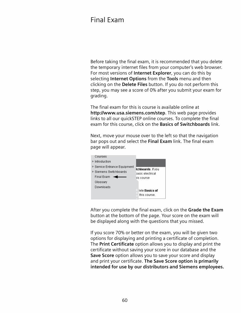
Next, move your mouse over to the left so that the navigation bar pops out and select the Final Exam link. The final exam page will appear.
After you complete the final exam, click on the Grade the Exam button at the bottom of the page. Your score on the exam will be displayed along with the questions that you missed.
If you score 70% or better on the exam, you will be given two options for displaying and printing a certificate of completion. The Print Certificate option allows you to display and print the certificate without saving your score in our database and the Save Score option allows you to save your score and display and print your certificate. The Save Score option is primarily intended for use by our distributors and Siemens employees.