Embed Size (px)
Citation preview
FLOW TRANSMITTER 8035
E-1-
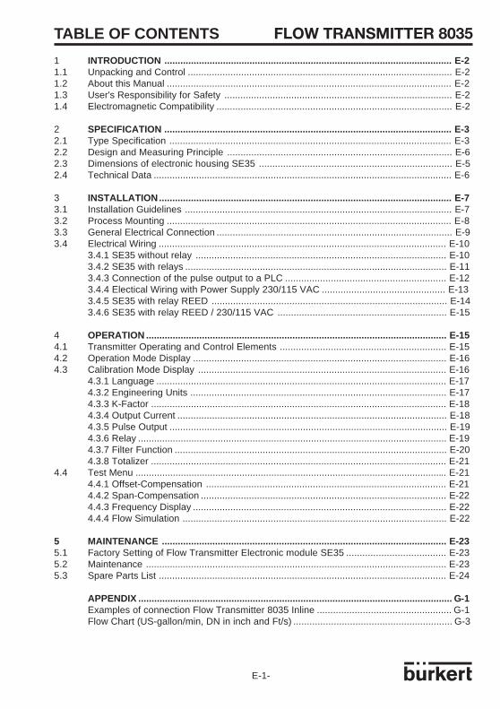
TABLE OF CONTENTS
1 INTRODUCTION ............................................................................................................ E-21.1 Unpacking and Control ................................................................................................... E-21.2 About this Manual ........................................................................................................... E-21.3 User's Responsibility for Safety ..................................................................................... E-21.4 Electromagnetic Compatibility ........................................................................................ E-2
2 SPECIFICATION ............................................................................................................ E-32.1 Type Specification .......................................................................................................... E-32.2 Design and Measuring Principle .................................................................................... E-62.3 Dimensions of electronic housing SE35 ........................................................................ E-52.4 Technical Data ................................................................................................................ E-6
3 INSTALLATION.............................................................................................................. E-73.1 Installation Guidelines .................................................................................................... E-73.2 Process Mounting ........................................................................................................... E-83.3 General Electrical Connection ........................................................................................ E-93.4 Electrical Wiring ............................................................................................................ E-10
3.4.1 SE35 without relay .............................................................................................. E-103.4.2 SE35 with relays .................................................................................................. E-113.4.3 Connection of the pulse output to a PLC ............................................................ E-123.4.4 Electical Wiring with Power Supply 230/115 VAC .............................................. E-133.4.5 SE35 with relay REED ........................................................................................ E-143.4.6 SE35 with relay REED / 230/115 VAC ............................................................... E-15
4 OPERATION ................................................................................................................. E-154.1 Transmitter Operating and Control Elements .............................................................. E-154.2 Operation Mode Display ............................................................................................... E-164.3 Calibration Mode Display ............................................................................................. E-16
4.3.1 Language ............................................................................................................. E-174.3.2 Engineering Units ................................................................................................ E-174.3.3 K-Factor ............................................................................................................... E-184.3.4 Output Current ..................................................................................................... E-184.3.5 Pulse Output ........................................................................................................ E-194.3.6 Relay .................................................................................................................... E-194.3.7 Filter Function ...................................................................................................... E-204.3.8 Totalizer ............................................................................................................... E-21
4.4 Test Menu ..................................................................................................................... E-214.4.1 Offset-Compensation .......................................................................................... E-214.4.2 Span-Compensation ............................................................................................ E-224.4.3 Frequency Display ............................................................................................... E-224.4.4 Flow Simulation ................................................................................................... E-22
5 MAINTENANCE ........................................................................................................... E-235.1 Factory Setting of Flow Transmitter Electronic module SE35 ..................................... E-235.2 Maintenance ................................................................................................................. E-235.3 Spare Parts List ............................................................................................................ E-24
APPENDIX ...................................................................................................................... G-1Examples of connection Flow Transmitter 8035 Inline .................................................. G-1Flow Chart (US-gallon/min, DN in inch and Ft/s) ........................................................... G-3

E-2-
FLOW TRANSMITTER 8035
Dear Customer,
Before installing or mounting this device,please take our advice and read the entiremanual thoroughly.
This will enable you to fully profit from all ofthe advantages offered by this product.
1.1 Unpacking and Control
Please verify that the product is completeand free from any damage.
If there is any loss or damage, please contactyour local Bürkert subsidiary.
1.2 About this Manual
This manual does not contain any warrantystatement. Please refer to our general termsof sale and delivery.Only properly-trained staff should install and/or repair this product. If difficultiesshould occur at the time of installation,please contact your nearest Bürkert salesoffice for assistance.
1.3 User's Responsibility for Safety
Bürkert manufactures a broad range of flowtransmitters. While each of these productsis designed to operate in a wide variety ofapplications, it is the user's responsibility toselect a transmitter model that is appropriatefor the application, install it properly, andmaintain all components. Special attentionmust be paid to the chemical resistance ofthe transmitter against the fluids which aredirectly contacting the product.
This symbol appears in the manualto call special attention toinstructions that affect the safe
installation, function and use of the product.
1.4 Electromagnetic compatibility
This device conforms to the EMC-Directiveof the European Union 89/336/EEC.In order to comply with this directive, thewiring instructions must be followed.
1 INTRODUCTION
!
FLOW TRANSMITTER 8035
E-3-
2 SPECIFICATION
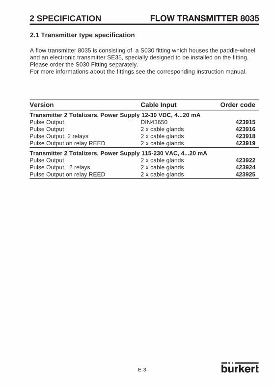
2.1 Transmitter type specification
A flow transmitter 8035 is consisting of a S030 fitting which houses the paddle-wheeland an electronic transmitter SE35, specially designed to be installed on the fitting.Please order the S030 Fitting separately.For more informations about the fittings see the corresponding instruction manual.
Version Cable Input Order code
Transmitter 2 Totalizers, Power Supply 12-30 VDC, 4...20 mAPulse Output DIN43650 423915Pulse Output 2 x cable glands 423916Pulse Output, 2 relays 2 x cable glands 423918Pulse Output on relay REED 2 x cable glands 423919
Transmitter 2 Totalizers, Power Supply 115-230 VAC, 4...20 mAPulse Output 2 x cable glands 423922Pulse Output, 2 relays 2 x cable glands 423924Pulse Output on relay REED 2 x cable glands 423925

E-4-
FLOW TRANSMITTER 80352 SPECIFICATION
2.2 Design and Measuring Principle
Design
The flow transmitter 8035 consists of anelectronic IP65 housing SE35 set by quarterturn on the fitting S030. The electronichousing integrates the electronic board withdisplay, programmation keys and also a thetransducer (coil). The paddle-wheel ismounted in the fitting..
The transducer component converts themeasured signal and displays the actualvalue.The output signals are provided via a 4-pole plug or via two cable glands.
Measuring Principle
When liquid flows through the pipe, 4magnets inserted in the paddle-wheel set inrotation produce a measuring signal in the8035 transducer.
The frequency modulated induced voltageis proportional to the flow velocity of the fluid.A conversion coefficient, specific to eachpipe (size and material) enables theconversion of this frequency into flowrate.This coefficient (Factor-K in pulse/liter) isavailable in the instruction manual of theinline fitting (S030).
The transducer without relay functions in a2-wire circuit and requires a power supplyof 12...30 VDC. A 4...20 mA standard signalis available as output signal, proportional tothe flow rate. A pulse output with transistoropen collector NPN/PNP or relay Reed(option) is available.
The transducer with two additional relaysfunctions in a 3-wire circuit. Limit values arefreely adjustable (not available with relayReed option).
The flow transmitter 8035 measures a flowrate from 0.3 m/s (1.0 ft/s).
The flow transmitter electronic module SE35can receive a power supply 230/115 VACas an option.

FLOW TRANSMITTER 8035
E-5-
Fig. 2.1 Electronic enclosure SE35 external dimensions
2.3 Electronic module SE35: External dimensions
DN H
mm "
15 122 4.81
20 119 4.69
25 120 4.73
32 123 4.85
40 127 5.00
50 134 5.28
The height H isindependant from theconnection type andmaterial of the fitting.
2 SPECIFICATION

E-6-
FLOW TRANSMITTER 80352 SPECIFICATION
2.4 Technical DataPipe diameter from DN08 to DN65 (1/4" to 2"1/2)Measuring range 0,3 to 10 m/s (1.0 to 32.8 ft/s)flow range as from 1 l/min (DN08 pipe, 0.3 m/s flow velocity)flow range as from 0.3 gpm (1/4" pipe, 1.0 ft/s flow velocity)
Plastic fitting PVC; PP; PVDFPressure class PN10Fluid temperature max PVC: 50 °C (132°F); PP: 80 °C (176°F); PVDF: 100 °C (212°F)
Metal fitting Stainless-stel (316L 1.4404); brassPressure class PN16Fluid temperature max: 100 °C (212°F)
Ambiant temperature 0 to 60 °C (32 to 140 °F)Storage temperature 0 to 60 °C (32 to 140 °F)Relative humidity 80 %Enclosure IP65Measuring error 1.With In-line calibration (Teach-In):
≤±0.5% o.F.S. (at 10 m/s) *2.With standard mean K-Factor:≤± (0.5% o.F.S. +2.5% o.R.) *
Linearity ≤±0.5% o.F.S. (at 10 m/s) *Repeatability 0.4% o.R. *Display 15 x 60 mm LCD 8 digits, alphanumeric,
15 segments, 9 mm highSensor holder PVDF, PP, PVC, SS 316L (1.4404), BrassPaddle-wheel PVDFAxis and bearing ceramic; O-rings FPMElectronics housing PC; Front plate foil polyesterVoltage supply 12...30 VDC (115/230 V as an option)
Output signal 4...20 mALoad max. 900 Ω at 30V; max. 500 Ω at 24V; max. 100 Ω at 15V;
max. 800 Ω at 115/230 VACPulse output Open collector NPN and PNP,
0...30 V, 100 mA, protected, freely adjustablePulse output relay REED Contact relay REED, closing 0,1 s.
Opening depending on flow rate (0.1 s min. U max: 34 V, 0.2 A
Relay output (optional) 2 relays, 3 A, 220 V, freely adjustable
(*) Under reference conditions i.e. measuring fluid water, ambient and water temperature 20°C,applying the minimum inlet and outlet pipe straights, matched pipe dimensions.o.F.S. = of standard Full Scale (10 m/s) - o.R. = of Reading
FLOW TRANSMITTER 8035
E-7-
1 92 3 4 5 6 7 8 10m/s
2
4
6
8
10
-2
-4
-6
-8
-10
% max.error
0.5% o.F.S. + 2.5 o.R.0.5% o.F.S.
Flow velocity m/sMea
suri
ng e
rror
% o
f m
easu
red
valu
e (*
)
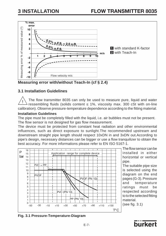
1 with standard K-factor2 with Teach-In
Measuring error with/without Teach-In (cf § 2.4)
-50 -30 -10 +10 +30 +50 +70 +90 +110 +1300
21
3456
789
101112
13141516
PVC + PP
PVDFPVDF (PN 10)
PVC (PN 10)
PP (PN 10)
3 INSTALLATION
Installation GuidelinesThe pipe must be completely filled with the liquid, i.e. air bubbles must not be present.The flow sensor is not designed for gas flow measurement.The device must be protected from constant heat radiation and other environmentalinfluences, such as direct exposure to sunlight.The recommended upstream anddownstream straight pipe length should respect 10xDN in and 3xDN out.According topipe's design, necessary distances can be bigger or use a flow tranquilizer to obtain thebest accuracy. For more informations please refer to EN ISO 5167-1.
The flow sensor can beinstalled in eitherhorizontal or verticalpipe.The suitable pipe sizeis selected using thediagram on the endpages (G-3). Pressureand temperatureratings must berespected accordingto to the selected fittingmaterial.(see fig. 3.1)
!
Fig. 3.1 Pressure-Temperature-Diagram
3.1 Installation Guidelines
The flow transmitter 8035 can only be used to measure pure, liquid and waterressembling fluids (solids content ≤ 1%, viscosity max. 300 cSt with on-line
calibration). Observe pressure-temperature dependence according to the fitting material.
Pbar
T° C
Application range for complete device
E-8-
FLOW TRANSMITTER 80353 INSTALLATION
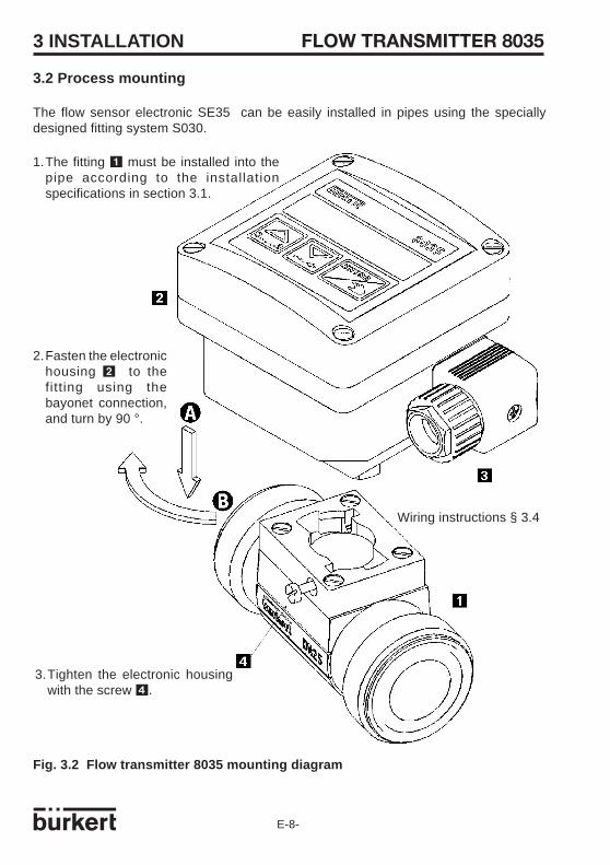
3.2 Process mounting
The flow sensor electronic SE35 can be easily installed in pipes using the speciallydesigned fitting system S030.
1.The fitting 1 must be installed into thepipe according to the installationspecifications in section 3.1.
3.Tighten the electronic housingwith the screw 4.
2.Fasten the electronichousing 2 to thefitt ing using thebayonet connection,and turn by 90 °.
Wiring instructions § 3.4
Fig. 3.2 Flow transmitter 8035 mounting diagram

FLOW TRANSMITTER 8035
E-9-
3 INSTALLATION
Wiring via cable plug DIN 43650
Standard DIN 43650 plug connector withcable gland, pipe cross section max. 1.5mm2, IP65 rating (fig. 2). Open plug andwire according following istructions:
1: L+ (12...30 VDC)2: Pulse output Ay: Pulse output B3: L-
3.4. Electrical wiring
3.4.1 Connecting Transmitter SE35 without relay
3.3 General Electrical Connection
The connecting line conducts the measuring signal and must not be installed in combinationwith high voltage or high frequency carrying lines. If a combined installation cannot beavoided, either keep a min. space of 30 cm (approx. 1 ft) or use coax cables. When usingcoax cables observe faultless grounding of the shield. For normal operating conditions,the measuring signal can be transmitted by a simple cable of 0.75 mm2 cross section.Always use a coax cable in case of doubt.The power supply must be of good quality (filtrated and regulated).
Note: For EMC purposes,the earth must be connected via the earth lug on the sideof the enclosure . This point must be connected locally to a good earth.
Fig. 3.3 DIN 43650 cable plug assembly
Note: The pulse output of the TransmitterSE35 can easily be connected to aPLC.(fig. 3.5).
1
32
2
13
4
5
- Remove part [3] from part [2].- Wire according to pin assignment.- Replace part [3].- Tighten the cable gland [5].- Place gasket [4] between the DIN43650 connector and the fixed connector of the 8035.- Connect the DIN 43650 connector to the 8035.- Tighten screw [1].
E-10-
FLOW TRANSMITTER 8035
654321
3 INSTALLATION
PLC
PLC
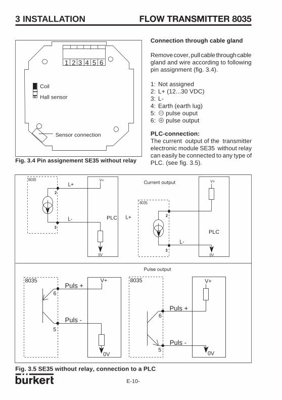
Connection through cable gland
Remove cover, pull cable through cablegland and wire according to followingpin assignment (fig. 3.4).
1: Not assigned2: L+ (12...30 VDC)3: L-4: Earth (earth lug)5: B pulse ouput6: A pulse output
Sensor connection
Fig. 3.5 SE35 without relay, connection to a PLC
8035 V+L+
L-
0V 0V
V+
L+
L-
8035
2
3
2
3
Fig. 3.4 Pin assignement SE35 without relay
PLC-connection:The current output of the transmitterelectronic module SE35 without relaycan easily be connected to any type ofPLC. (see fig. 3.5).
V+
0V
Puls +
Puls -
0V
V+
Puls +
Puls -
8035 8035
6
5
6
5
Coil
Hall sensor
Current output
Pulse output
FLOW TRANSMITTER 8035
E-11-
0V
V+
4...20 mA
L-
8035L+
8035 V+
L+
4...20 mA
0V
L-
Position A Position B 2
1
3
2
1
3
3 INSTALLATION
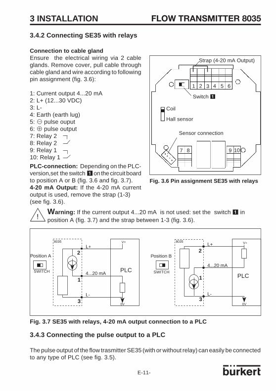
Fig. 3.6 Pin assignment SE35 with relays
Warning: If the current output 4...20 mA is not used: set the switch 1 inposition A (fig. 3.7) and the strap between 1-3 (fig. 3.6).!
PLC
3.4.2 Connecting SE35 with relays
Connection to cable glandEnsure the electrical wiring via 2 cableglands. Remove cover, pull cable throughcable gland and wire according to followingpin assignment (fig. 3.6):
1: Current output 4...20 mA2: L+ (12...30 VDC)3: L-4: Earth (earth lug)5: B pulse ouput6: A pulse output7: Relay 28: Relay 29: Relay 110: Relay 1
PLC-connection: Depending on the PLC-version,set the switch 1 on the circuit boardto position A or B (fig. 3.6 and fig. 3.7).4-20 mA Output: If the 4-20 mA currentoutput is used, remove the strap (1-3)(see fig. 3.6).
3.4.3 Connecting the pulse output to a PLC
The pulse output of the flow trasmitter SE35 (with or without relay) can easily be connectedto any type of PLC (see fig. 3.5).
PLCSWITCHSWITCH
Fig. 3.7 SE35 with relays, 4-20 mA output connection to a PLC
1 2 3 4 5 6
7 8 9 10
Strap (4-20 mA Output)
Switch 1
Sensor connection
Coil
Hall sensor
E-12-
FLOW TRANSMITTER 8035
1 2 3 4 5 6
mA+
-
7 8 9 10
1 2 3 4 5 6
mA+
-
3 INSTALLATION
Warning: If the current output 4...20 mA is not used: set the switch 1 inposition A (fig. 3.7) and the strap across 1-3 (fig. 3.6).
Switch 1 inposition A
Sensor connectionSensor connection
Strap (cf §3.4.2)Strap (cf §3.4.2)
SE35 without relay SE35 with relays
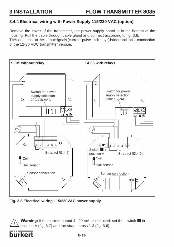
Fig. 3.8 Electrical wiring 115/230VAC power supply
!
3.4.4 Electrical wiring with Power Supply 115/230 VAC (option)
Remove the cover of the transmitter, the power supply board is in the bottom of thehousing. Pull the cable through cable gland and connect according to fig. 3.8.The connection of the output signals (current, pulse and relays) is identical to the connectionof the 12-30 VDC transmitter version.
Coil
Hall sensor
Coil
Hall sensor
Switch for powersupply selection230/115 VAC
Switch for powersupply selection230/115 VAC
FLOW TRANSMITTER 8035
E-13-
0V
V+
4...20 mA
L-
8035L+
8035 V+
L+
4...20 mA
0V
L-
Position A Position B 2
1
3
2
1
3
3 INSTALLATION REED
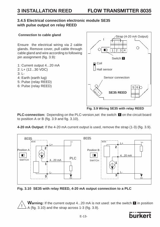
PLC-connection: Depending on the PLC-version,set the switch 1 on the circuit boardto position A or B (fig. 3.9 and fig. 3.10).
4-20 mA Output: If the 4-20 mA current output is used, remove the strap (1-3) (fig. 3.9).
PLC
8035 8035
Warning: If the current output 4...20 mA is not used: set the switch 1 in positionA (fig. 3.10) and the strap across 1-3 (fig. 3.9).!
Strap (4-20 mA Output)
Sensor connection
Connection to cable gland
Ensure the electrical wiring via 2 cableglands. Remove cover, pull cable throughcable gland and wire according to followingpin assignment (fig. 3.9):
1: Current output 4...20 mA2: L+ (12...30 VDC)3: L-4: Earth (earth lug)5: Pulse (relay REED)6: Pulse (relay REED)
Switch 1
1 2 3 4
5 6
3.4.5 Electrical connection electronic module SE35with pulse output on relay REED
Fig. 3.9 Wiring SE35 with relay REED
SWITCHSWITCH
Fig. 3.10 SE35 with relay REED, 4-20 mA output connection to a PLC
Coil
Hall sensor
SE35 REED
E-14-
FLOW TRANSMITTER 8035
1 2 3 4
5 6
mA
3 INSTALLATION REED
If the current output 4...20 mA is not used: set the switch 1 in position A (fig.3.10) and the strap across 1-3 (fig. 3.9).!
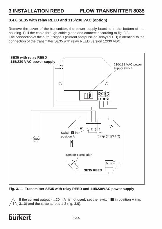
Fig. 3.11 Transmitter SE35 with relay REED and 115/230VAC power supply
3.4.6 SE35 with relay REED and 115/230 VAC (option)
Remove the cover of the transmitter, the power supply board is in the bottom of thehousing. Pull the cable through cable gland and connect according to fig. 3.8.The connection of the output signals (current and pulse on relay REED) is identical to theconnection of the transmitter SE35 with relay REED version 12/30 VDC.
Sensor connection
Strap (cf §3.4.2)Switch 1 inposition A
SE35 with relay REED115/230 VAC power supply
SE35 REED
230/115 VAC powersupply switch
FLOW TRANSMITTER 8035
E-15-
4 OPERATION
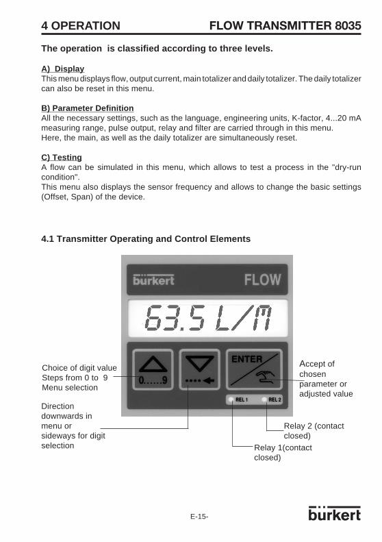
Directiondownwards inmenu orsideways for digitselection
Accept ofchosenparameter oradjusted value
Choice of digit valueSteps from 0 to 9Menu selection
4.1 Transmitter Operating and Control Elements
Relay 2 (contactclosed)
Relay 1(contactclosed)
The operation is classified according to three levels.
A) DisplayThis menu displays flow, output current, main totalizer and daily totalizer. The daily totalizercan also be reset in this menu.
B) Parameter DefinitionAll the necessary settings, such as the language, engineering units, K-factor, 4...20 mAmeasuring range, pulse output, relay and filter are carried through in this menu.Here, the main, as well as the daily totalizer are simultaneously reset.
C) TestingA flow can be simulated in this menu, which allows to test a process in the "dry-runcondition".This menu also displays the sensor frequency and allows to change the basic settings(Offset, Span) of the device.
E-16-
FLOW TRANSMITTER 8035
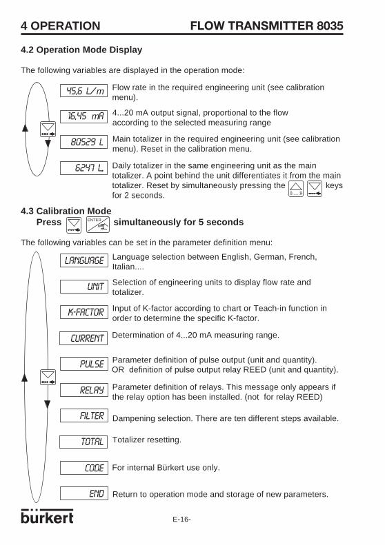
4.3 Calibration Mode Press simultaneously for 5 seconds
The following variables can be set in the parameter definition menu:
4 OPERATION
Language selection between English, German, French,Italian....
Selection of engineering units to display flow rate andtotalizer.
Input of K-factor according to chart or Teach-in function inorder to determine the specific K-factor.
Determination of 4...20 mA measuring range.
Parameter definition of pulse output (unit and quantity).
Parameter definition of relays. This message only appears ifthe relay option has been installed. (not for relay REED)
LANGUAGE
UNIT
K-FACTOR
CURRENT
PULSE
RELAY
FILTER
TOTAL
CODE
END
4.2 Operation Mode Display
The following variables are displayed in the operation mode:
ENTER
45,6 L/m
16,45 mA
80529 L
6247 L..
Flow rate in the required engineering unit (see calibrationmenu).
4...20 mA output signal, proportional to the flowaccording to the selected measuring range
Main totalizer in the required engineering unit (see calibrationmenu). Reset in the calibration menu.
Daily totalizer in the same engineering unit as the maintotalizer. A point behind the unit differentiates it from the maintotalizer. Reset by simultaneously pressing the keysfor 2 seconds. 0......9
OR definition of pulse output relay REED (unit and quantity).
Dampening selection. There are ten different steps available.
Totalizer resetting.
For internal Bürkert use only.
Return to operation mode and storage of new parameters.
FLOW TRANSMITTER 8035
E-17-
LANGUAGE ENGLISH
DEUTSCH
FRANCAIS
ITALIANOUNIT
ENTER
ENTER
UNIT LIT/SEC
LIT/MIN
LIT/H
M3/MIN
K-FACTOR
M3/H
US GAL/S
US GAL/M
US GAL/H
IMP GA/S
IMP GA/M
IMP GAL/H
FLOW
TOTAL
L
M3
US GAL
IMP GAL
DEC PT 0
DEC PT 1
DEC PT 20......9
ENTER
ENTER
ENTER
ENTER
ENTER
ENTER
DEC PT 3
4 OPERATION
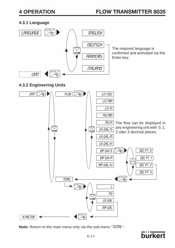
The required language isconfirmed and activated via theEnter-key.
The flow can be displayed inany engineering unit with 0, 1,2 oder 3 decimal places.
4.3.1 Language
Note: Return to the main menu only via the sub-menu "TOTAL".
4.3.2 Engineering Units

E-18-
FLOW TRANSMITTER 8035
K-FACTOR
0000.0 L
CURRENT 0100.0 L
FILL END
K= 79.30
TEACH NO
TEACH Y
0......9
CURRENT
K= =00.00
K= 117.60
0......9
ENTER ENTER
ENTER
ENTER ENTER
ENTERENTER
4 OPERATION
4.3.3 K-Factor
The K-factor of the fitting (refer to S030 reference manual) is entered in this menu .The "Teach in" function allows to practically detemine the application specific K-factor.The user only needs to run a known quantity through his system.
Example: In order to determine a quantity the most accurately possible, the user shall filla tank of 100 litres. When the message "TEACH YES" appears, he presses the Enter key tostart the measuring procedure. The message "FILL END" (end of filling) will appear. He thenswitches on a pump or opens a valve. As soon as his tank is full, he switches off the pumpor closes the valve. Pressing Enter stops the measurement. The user will then be askedto enter the quantity (100 litres). The calculated K-factor is displayed after validation.
Note: The device uses the K-factor entered or determined at last.
Enter of K-factor asspecified in the charts.
Start of measurement. Stop ofmeasurement.
Indication of calculatedK-factor.
4.3.4 Output current
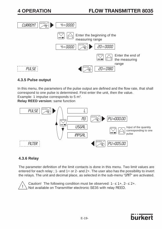
The measuring range of the flow, corresponding to the 4...20 mA output current is enteredhere. E.g. 0 to 180 l/min corresponds to 4...20 mA. The beginning of the measuring rangecan be larger than the end of it, i.e. 0 to 180 l/min corresponds to 20...4 mA (inverted outputsignal).The settings (unit and decimal place), as selected for the flow indication will apply.
In case of electronic internal failure, the current output is set to 22 mA.
Enter the measured quantity.Same unit as for flow.
!
FLOW TRANSMITTER 8035
E-19-
PULSE
FILTER
ENTER
PU=000.00
PU=005.00
0......9
ENTER
ENTER
L
M3
USGAL
IMPGAL
CURRENT
PULSE
4= 0000
0......9
ENTER
20= 0000
20= 0180
0......9
ENTER
ENTER
4= 0000
Enter the beginning of themeasuring range
Enter the end ofthe measuringrange
4 OPERATION
4.3.5 Pulse output
In this menu, the parameters of the pulse output are defined and the flow rate, that shallcorrespond to one pulse is determined. First enter the unit, then the value.Example: 1 impulse corresponds to 5 m3.Relay REED version: same function
Input of the quantitycorresponding to onepulse
!
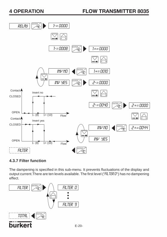
4.3.6 Relay
The parameter definition of the limit contacts is done in this menu. Two limit values areentered for each relay ; 1- and 1+ or 2- and 2+. The user also has the possibility to invertthe relays. The unit and decimal place, as selected in the sub-menu "UNIT" are activated.
Caution! The following condition must be observed: 1- ≤ 1+, 2- ≤ 2+.Not available on Transmitter electronic SE35 with relay REED.
E-20-
FLOW TRANSMITTER 8035
FILTER
TOTAL
ENTER
ENTER
FILTER 0
FILTER 9
0......9
RELAY
FILTER
1-= 0000
1-= 0008
0......9
ENTER
1+= 0000
2+= 0044
0......9
ENTER
ENTER
INV NO
INV YES 2-= 0000
2-= 0040
0......9
ENTER
2+= 0000
0......9
ENTER
INV NO
INV YES
ENTER
1+= 0010ENTER
1- (8) 1+ (10)
CLOSED
OPEN
Invert no
1- (8) 1+ (10)
CLOSED
OPEN
Invert yes
Contact
FlowContact
Flow
4 OPERATION
4.3.7 Filter function
The dampening is specified in this sub-menu. It prevents fluctuations of the display andoutput current.There are ten levels available. The first level ("FILTER 0") has no dampeningeffect.
FLOW TRANSMITTER 8035
E-21-
OFFSET
SPAN
OF= 4.00
OF= 4.02
0......9
ENTER
ENTER
OFFSET
SPAN
FREQUENC
FLOW
END
TOTAL
CODE
ENTER
ENTER
RES NO
RES YES
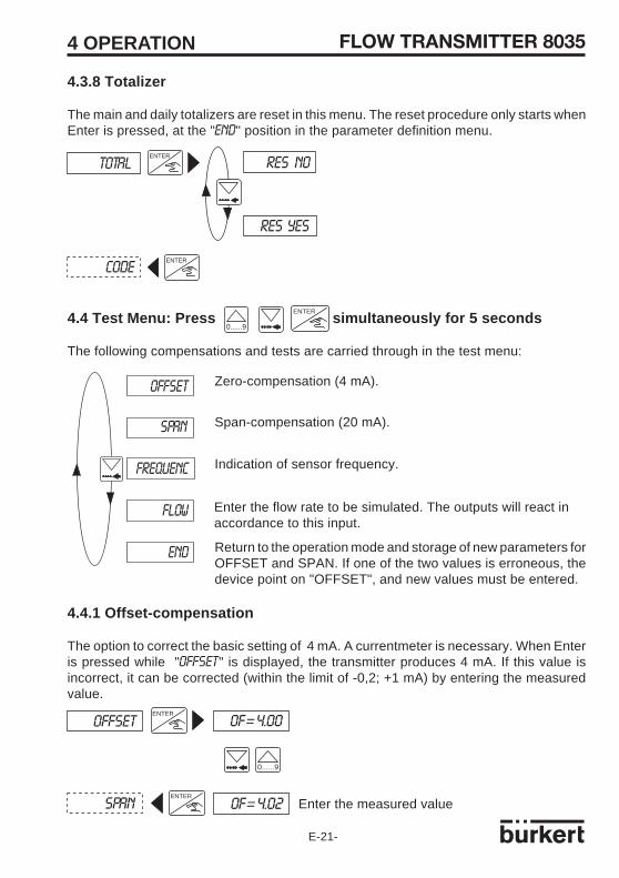
4.3.8 Totalizer
The main and daily totalizers are reset in this menu. The reset procedure only starts whenEnter is pressed, at the "END" position in the parameter definition menu.
4.4.1 Offset-compensation
The option to correct the basic setting of 4 mA. A currentmeter is necessary. When Enteris pressed while "OFFSET" is displayed, the transmitter produces 4 mA. If this value isincorrect, it can be corrected (within the limit of -0,2; +1 mA) by entering the measuredvalue.
Enter the measured value
4 OPERATION
4.4 Test Menu: Press simultaneously for 5 seconds
The following compensations and tests are carried through in the test menu:
Zero-compensation (4 mA).
Span-compensation (20 mA).
Indication of sensor frequency.
Enter the flow rate to be simulated. The outputs will react inaccordance to this input.
Return to the operation mode and storage of new parameters forOFFSET and SPAN. If one of the two values is erroneous, thedevice point on "OFFSET", and new values must be entered.
ENTER
0......9
E-22-
FLOW TRANSMITTER 8035
FLOW
FLOW
00.00L/S
46.25L/S
0......9
ENTER
ENTER
FREQUENC
FLOW
195.3 HZENTER
ENTER
SPAN
FREQUENC
SP=20.00
SP=19.90
0......9
ENTER
ENTER
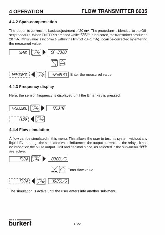
4.4.2 Span-compensation
The option to correct the basic adjustment of 20 mA. The procedure is identical to the Off-set procedure. When ENTER is pressed while "SPAN" is indicated, the transmitter produces20 mA. If this value is incorrect (within the limit of -1/+1 mA), it can be corrected by enteringthe measured value.
Enter the measured value
4.4.3 Frequency display
Here, the sensor frequency is displayed until the Enter key is pressed.
4.4.4 Flow simulation
A flow can be simulated in this menu. This allows the user to test his system without anyliquid. Eventhough the simulated value influences the output current and the relays, it hasno impact on the pulse output. Unit and decimal place, as selected in the sub-menu "UNIT"are active.
Enter flow value
The simulation is active until the user enters into another sub-menu.
4 OPERATION
FLOW TRANSMITTER 8035
E-23-
4 OPERATION
5 Maintenance
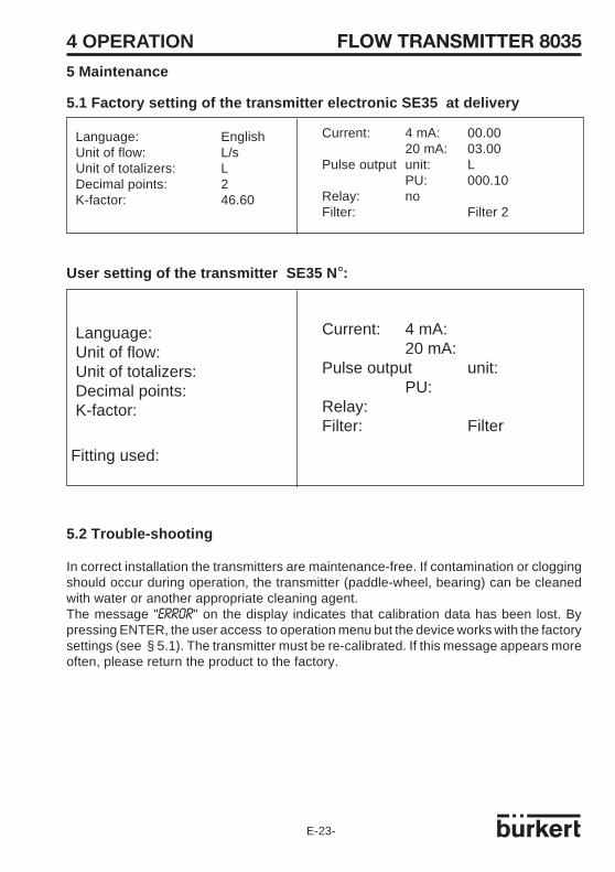
5.1 Factory setting of the transmitter electronic SE35 at delivery
5.2 Trouble-shooting
In correct installation the transmitters are maintenance-free. If contamination or cloggingshould occur during operation, the transmitter (paddle-wheel, bearing) can be cleanedwith water or another appropriate cleaning agent.The message "ERROR" on the display indicates that calibration data has been lost. Bypressing ENTER, the user access to operation menu but the device works with the factorysettings (see § 5.1). The transmitter must be re-calibrated. If this message appears moreoften, please return the product to the factory.
Current: 4 mA: 00.0020 mA: 03.00
Pulse output unit: LPU: 000.10
Relay: noFilter: Filter 2
Language: EnglishUnit of flow: L/sUnit of totalizers: LDecimal points: 2K-factor: 46.60
User setting of the transmitter SE35 N °:
Current: 4 mA:20 mA:
Pulse output unit:PU:
Relay:Filter: Filter
Language:Unit of flow:Unit of totalizers:Decimal points:K-factor:
Fitting used:

E-24-
FLOW TRANSMITTER 80355 MAINTENANCE
Position Specification Order code1 Cover with screws, front plate and PCB with relays 4252502 Cover with screws, front plate and PCB without relay 4252493 Cover with screws, front plate and PCB with relay REED 425251
4 Power supply board 115/230 VAC 419581
5 Cable plug DIN 43650 with cable gland (type 2508) 4388116 Cable plug DIN 43650 with NPT 1/2" reduction (type 2509) 162673
7+9+10+12 Set incl. 2 cable glands M20x1,5 + 2 neoprene flat gasketsfor cable gland or screwed plug + 2 screwed plugsM20x1,5 + 2 multiway seals 2x6 mm 449755
8+9+10 Set incl. 2 reductions M20x1,5 / NPT1/2'' (mounted gasket)+ 2 neoprene flat gaskets for screwed plug+ 2 screwed plugs M20x1,5 551782
11+12 Set incl. 1 obturator for cable gland M20x1,5 + 1 multiwayseal 2x6 mm for cable gland + 1 black EPDM gasketfor the sensor + 1 mounting instruction sheet 551775
13 + 5 Sensor housing with plug connector DIN 43650 (type 2508) 425246
14 Sensor housing for 2 cable glands M20x1.5 + coil function 42524714 Sensor housing for 2 cable glands M20x1.5 + hall function 425248
Instruction manual Fitting S030 426107
5.3 Spare Parts List
Transmitter electronic module SE35 4-20 mA ; pulse output, 2 totalizers
12
13
1 2 3
4
5 6
8
9
11
7
10
14
NPT 1/2
G-1-
TRANSMITTER 8035
8035
4-20 mA
R+
-
+
-+
-
24 V=
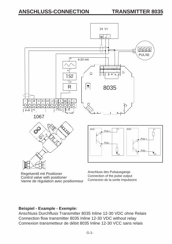
Regelventil mit PositionerControl valve with positionerVanne de régulation avec positionneur
PULSE
-+
-+
Beispiel - Example - Exemple:Anschluss Durchfluss Transmitter 8035 Inline 12-30 VDC ohne RelaisConnection flow transmitter 8035 Inline 12-30 VDC without relayConnexion transmetteur de débit 8035 Inline 12-30 VCC sans relais
ANSCHLUSS-CONNECTION
Anschluss des PulsausgangsConnection of the pulse outputConnexion de la sortie impulsions
1067
V+
0V
Puls +
Puls -
0V
V+
Puls +
Puls -
8035 8035
6
5
6
5

G-2-
TRANSMITTER 8035
8035
4-20 mA
V=V
V=V
MagnetventilSolenoid valveElectrovanne
PilotventilPilot valveVanne pilote
R+
-
+
-
7.50+
-
24 V=
Regelventil mit PositionerControl valve with positionerVanne de régulation avec positionneur
0 6 6 6PULSE
-+
-+
Beispiel - Example - Exemple:Anschluss Durchfluss Transmitter 8035 Inline 12-30 VDC mit RelaisConnection flow transmitter 8035 Inline 12-30 VDC with relaysConnexion transmetteur de débit 8035 Inline 12-30 VCC avec relais
ANSCHLUSS-CONNECTION
G-3-
TRANSMITTER 8035
Dur
chflu
ss-F
low
-Déb
it
Auswahlbeispiel:Selection example:Exemple:
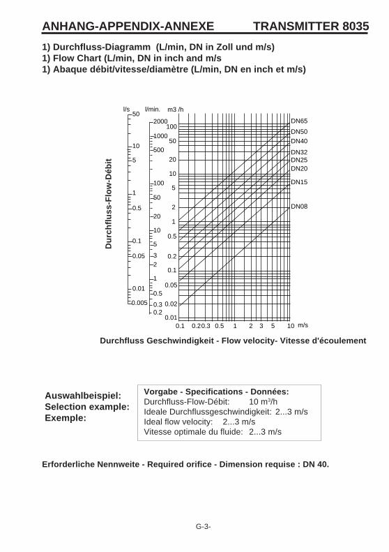
Vorgabe - Specifications - Données:Durchfluss-Flow-Débit: 10 m3/hIdeale Durchflussgeschwindigkeit: 2...3 m/sIdeal flow velocity: 2...3 m/sVitesse optimale du fluide: 2...3 m/s
Durchfluss Geschwindigkeit - Flow velocity- Vitesse d'écoulement
1) Durchfluss-Diagramm (L/min, DN in Zoll und m/s)1) Flow Chart (L/min, DN in inch and m/s1) Abaque débit/vitesse/diamètre (L/min, DN en inch et m/s)
ANHANG-APPENDIX-ANNEXE
Erforderliche Nennweite - Required orifice - Dimension requise : DN 40.
l/s l/min. m3 /h50
10
5
1
0.5
0.1
0.05
0.01
0.005
1000
500
100
50
20
10
5
32
1
0.5
0.30.2
100
50
20
10
5
2
1
0.5
0.2
0.1
0.05
0.02
0.010.1 0.20.3 0.5 1 2 3 5 10
DN50
DN40
DN32DN25DN20
DN15
2000 DN65
DN08
m/s
G-4-
TRANSMITTER 8035
Dur
chflu
ss-F
low
-Déb
it
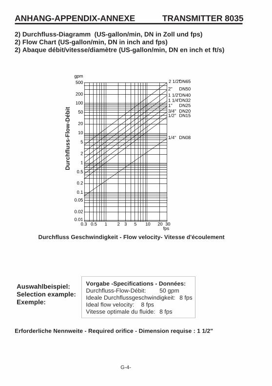
2) Durchfluss-Diagramm (US-gallon/min, DN in Zoll und fps)2) Flow Chart (US-gallon/min, DN in inch and fps)2) Abaque débit/vitesse/diamètre (US-gallon/min, DN en inch et ft/s)
Erforderliche Nennweite - Required orifice - Dimension requise : 1 1/2"
Auswahlbeispiel:Selection example:Exemple:
Vorgabe -Specifications - Données:Durchfluss-Flow-Débit: 50 gpmIdeale Durchflussgeschwindigkeit: 8 fpsIdeal flow velocity: 8 fpsVitesse optimale du fluide: 8 fps
Durchfluss Geschwindigkeit - Flow velocity- Vitesse d'écoulement
ANHANG-APPENDIX-ANNEXE
1
2
5
gpm500
200
20
10
0.5
0.2
0.1
0.05
0.02
0.0130200.3 0.5 1 2 3 5 10
2''1 1/2''1 1/4''1''3/4''1/2''
100
50
2 1/2''
1/4''
DN50DN40DN32DN25DN20DN15
DN65
DN08
fps
SERVICE
Bürkert ContromaticChina/HK Ltd.Cheng Du Representative OfficeRm. 502, Fuji BuildingNo. 26 ShududadaoDongfeng StreetChengdu P.R.CTel +86 (28) 443 1895Fax +86 (28) 445 1341
Bürkert ContromaticChina/HK Ltd.Guangzhou Representative OfficeRm. 1305, Tower 2Dong-Jun Plaza, 828-836Dongfeng, Road EastGuangzhou P.R.CTel +86 20 87 60 58 02Fax +86 20 87 60 49 79
DenmarkBürkert-Contromatic A/SHørkær 24DK-2730 HerlevTel +45 (44) 50 75 00Fax +45 (44) 50 75 75
FinlandBürkert OyAtomitie 5SF-00370 HelsinkiTel +358 (9) 549 706 00Fax +358 (9) 503 12 75
FranceBürkert ContromaticB.P. 21Triembach au ValF-67220 VilléTel +33 (0) 388 58 91 11Fax +33 (0) 388 57 09 61
Germany / DeutschlandBürkert Steuer- und RegeltechnikChristian-Bürkert-Straße 13-17D-74653 IngelfingenTel +49 7940 10-0Fax +49 7940 10 361
Niederlassung NRWHolzener Straβe 70D-58708 MendenTel +49 2373 96 81-0Fax +49 2373 96 81-52
Niederlassung FrankfurtAm Flugplatz 27D-63329 EgelsbachTel +49 6103 94 14-0Fax +49 6103 94 14-66
Niederlassung MünchenPaul-Gerhardt-Allee 24D-81245 MünchenTel +49 89 82 92 28-0Fax +49 89 82 92 28-50
Niederlassung BerlinBruno-Taut-Straβe 4D-12524 BerlinTel +49 30 67 97 17-0Fax +49 30 67 97 17-66
Niederlassung DresdenChristian Bürkert Straße 2D-01900 GroßröhrsdorfTel +49 35952 3 63 00Fax +49 35952 3 65 51
Niederlassung HannoverRendsburger Straße 12D-30569 HannoverTel +49 511 9 02 76-0Fax +49 511 9 02 76-66
Niederlassung StuttgartKarl-Benz-Straße 19D-70794 Filderstadt (Bernh.)Tel +49 711 4 51 10-0Fax +49 711 4 51 10-66
Great BritainBürkert Contromatic Ltd.Brimscombe Port Business ParkBrimscombe, Stroud, Glos.GL5 2QFTel. +44 (1453) 73 13 53Fax +44 (1453) 73 13 43
Hong KongBurkert Contromatic(China/HK) Ltd.Unit 708, Prosperity Centre77-81 Container Port RoadKwai Chung N.T.Hong KongTel +85 (2) 248 012 02Fax +85 (2) 241 819 45
IrelandBürkert Contromatic Ltd.Penrose Wharf centrePenrose WharfIRE-CorkTel +353 (21) 486 13 36Fax +353 (21) 733 23 65
ItalyBürkert Contromatic Italiana S.p.A.Centro Direzionale 'Colombirolo'Via Roma 74I-20060 Cassina De' Pecchi (MI)Tel +39 (02) 959 071Fax +39 (02) 959 07 251
AustraliaBurkert Fluid Control SystemsUnit 1 No.2, Welder RoadSeven Hills NSW 2147Tel +61 (2) 983 948 00Fax +61 (2) 967 461 67
AustriaBürkert Contromatic GmbHCentral and Eastern EuropeDiefenbachgasse 1-3A-1150 WienTel +43 (1) 894 13 33Fax +43 (1) 894 13 00
BelgiumBürkert Contromatic N.V/S.ABijkoevelaan 3B-2110 WijnegemTel +32 (3) 325 89 00,Fax +32 (3) 325 61 61
BrazilBürkert Contromatic Brasil LtdaRua Américo Brasilense 2171, cj 100704715-005 Sao Paulo/SP/BrasilTel +55 11 5182 0011,Fax +55 11 5182 8899
CanadaBürkert Contromatic Inc.760 Pacific Road, Unit 3Oakville, Ontario, L6L 6M5Tel +1 905 847 55 66,Fax +1 905 847 90 06
ChinaBürkert Contromatic(Suzhou) Co. Ltd.9-2, Zhu Yuan RoadNew District, SuzhouJiangsu, 215011 P.R.CTel +86 (512) 6808 19 16Fax +86 (512) 6824 51 06
Bürkert ContromaticChina/HK Ltd.Rm. 1313No. 103, Cao Bao RoadShanghai 200233 P.R.CTel +86 (21) 6427 1946Fax +86 (21) 6427 1945
Bürkert ContromaticChina/HK Ltd.Beijing OfficeRm. 808, Jing Tai BuildingNo. 24, JianguomenWaidajieBeijing 100022 P.R.CTel +86 (10) 65 15 65 08Fax +86 (10) 65 15 65 07

PolandBürkert Contromatic Sp.z.o.o.Bernardynska streetPL-02-904 WarszawaTel +48 22 840 60 10Fax +48 22 840 60 11
SingaporeBurkert Contromatic SingaporePte.Ltd.No.11 Playfair RoadSingapore 367986Tel +65 383 26 12Fax +65 383 26 11
SpainBürkert Contromatic S.A.Avda. Barcelona, 40E-08970 Sant Joan Despi,BarcelonaTel +34 (93) 477 79 80Fax +34 (93) 477 79 81
South AfricaBurkert Contromatic Pty.Ltd.P.O.Box 26260, East Rand 1462Republic of South AfricaTel +27 (11) 397 2900Fax +27 (11) 397 4428
SwedenBürkert Contromatic ABSkeppsbron 13 BS-21120 MalmöTel +46 (40) 664 51 00Fax +46 (40) 664 51 01
Bürkert Contromatic ABHavsörnstorget 21Box 1002S-12349 FarstaTel +46 (8) 724 01 27Fax +46 (8) 724 60 22
SwitzerlandBürkert-Contromatic AG InternationalBösch 71, P.O. BoxCH-6331 Hünenberg / ZGTel +41 41 785 66 66Fax +41 41 785 66 33
SERVICE
TaiwanBürkert Contromatic Taiwan Ltd.3F No. 475 Kuang-Fu South RoadR.O.C - Taipei CityTel +886 (0) 2 275 831 99Fax +886 (0) 2 275 824 99
TurkeyBürkert ContromatikAkiskan Kontrol Sistemleri Ticaret A.S1203/8 Sok. No. 2-EYenisehirIzmirTel +90 (232) 459 53 95Fax +90 (232) 459 76 94TzechiaBürkert Contromatic Spol.s.r.oProsenice c. 180CZ - 751 21 ProseniceTel +42 0641 226 180Fax +42 0641 226 181
USA/West/Main officeBurkert Contromatic Corp.2602 McGaw AvenueIrvine, CA 92614, USATel. +1 (949) 223 31 00Fax +1 (949) 223 31 98
JapanBürkert Contromatic Ltd.1-8-5 Asagaya MinamiSuginami-kuTokyo 166-0004Tel +81 (3) 5305 3610Fax +81 (3) 5305 3611
KoreaBürkert Contromatic Korea Co. Ltd.287-2, Doksan 4 DongKumcheon-KuSeoul 153-811Tel. +82 (2) 346 255 92Fax +82 (2) 346 255 94
MalaysiaBürkert Contromatic Singapore Pte. Ltd.Representative Officec/o TBP 222, Jalan Baru137000 Perai, PenangTel. +60 (4) 398 2410Fax +60 (4) 398 2182
NetherlandsBürkert Contromatic BVPostbus 1248NL-3600 BE MaarssenTel. +31 346 58 10 10Fax +31 346 56 37 17
New ZealandBurkert Contromatic Ltd.2A, Unit L, Edinburg StPenroseAucklandTel +64 (9) 622 28 40Fax +64 (9) 622 28 47
NorwayBürkert Contromatic A/SHvamstubben 17Box 243N-2026 SkjettenTel +47 (63) 84 62 10Fax +47 (63) 84 44 55
PhilippinesBürkert Contromatic Inc.8467, West Service Rd Km 14South Superhighway, SunvalleyParanaque City, Metro ManilaTel +63 (2) 776 43 84Fax +63 (2) 776 43 82