Embed Size (px)
Citation preview
First Edition 2019.1
T110、T210 Series
Inkjet Printer
OPERATION AND MAINTENANCE
MANUAL

1
CONTENTS
PART 1: HEALTH AND SAFETY
PART 2: DESCRIPTION
PART 3: SCREEN DESCRIPTION
SCREEN LOCK
INFORMATION EDITING MENU (1)
INFORMATION EDITING MENU (2)
FILE STORAGE
PRINT PARAMETERS
MECHANICAL PARAMETER (1)
MECHANICAL PARAMETER (2)
SERVICE MENU
PART 4: OPERATION
PART 5: DISPLAY MESSAGES AND FAULT FINDING
PART 6: REPAIR
PART 7: SPARES AND ACCESSORIES
PART 8: OPTIONS

HEALTH AND SAFETY
1-1
PART 1:HEALTH AND SAFETY
CONTENTS
Basic Requirements ........................................................................................... 2
Storage .............................................................................................................. 3
Fire Risk ............................................................................................................. 3
Spillages and Disposal ........................................................................................ 4
SYMBOLS ........................................................................................................... 5

HEALTH AND SAFETY
1-2
Basic Requirements
When used correctly, printing inks do not cause problems. However,
everybody using them should be familiar with the appropriate safety standards and
be aware of the precautions that should be taken. The following are basic
requirements.
Proper standards of industrial practice relating to cleanliness and tidiness
must be maintained.
• Inks and their containers must be stored and handled with care.
All who come into contact with inks must be properly instructed in their use.
Directions for safe working practices vary according to the environment. The
following are broad principles so that necessary precautions may be taken.
Contact with the mouth must be avoided. Therefore eating, drinking or
smoking, or any personal habits or actions which may transfer ink to the
mouth, must be avoided.
Contact with the eyes must be avoided. Suitable eye protection must always
be worn whenever there is any risk of splashing or misting. If ink does get
into the eyes, first aid treatment is to flood the affected eye for 15 minutes
with saline solution, (or clean water if saline solution is not available), taking
care not to allow the water to run into an unaffected eye. Medical aid must
be obtained immediately.
Most inks contain solvents which may injure the skin. Warning of this is
given on the SDSs. Barrier creams should be used and protective clothing
worn.
Many inks contain materials which vaporise easily and can be inhaled. Good
ventilation is necessary.
Any used cleaning materials, e.g. rags, paper wipes, are a potential fire
hazard. They must be collected for safe disposal after use.
After exposure to ink, all possible traces must be washed off as soon as
possible at the nearest washing facility.
Certain inks are allowed for use where they can be in indirect contact with
food. In these cases, the following precautions must be observed in addition
to those appropriate to hygiene:
The inks must only be used in printers supplied from new for use with these
inks. Any repairs and replacements must use genuine, new and unused
spare parts.
The inks must not be used in printers which have previously been used, at
any time, for any other purpose.
In other words, a printer using "FoodGrade" ink can be converted for use
with other inks, but a printer which has used other inks must not be
converted for use with food grade ink.

HEALTH AND SAFETY
1-3
Storage
Printing inks must be stored in well-ventilated buildings, or in areas set aside for the
purpose, chosen for safety in case of fire. Materials based on volatile, flammable
solvents must be stored in accordance with local regulations.
Fire Risk
For an electrical fire, do not use water. If water must be used, such as in the case of a
Nitro-cellulose ink fire (see below) the power MUST BE
REMOVED first.
Many inks used in ink jet printing contain Nitro-cellulose as the binder and remain
highly flammable when dry. Observe all warnings given on the machine and the
following safety instructions:
If there has been an accumulation of dried ink, do not use ferrous metal
(iron or steel) scrapers to remove it, as they can produce sparks
If dry Nitro-cellulose based ink ignites, it will generate its own oxygen and
can only be extinguished by lowering the temperature with water
• If a Nitro-cellulose fire occurs, ENSURE THAT THE ELECTRICAL POWER IS
IMMEDIATELY REMOVED FROM THE PRINTER BEFORE water is used to
extinguish the fire.
Fire risk is a most important consideration where printing inks are stored and used.
The degree of fire hazard will vary considerably from one type of ink or wash to
another.
Water-based inks will not burn, although inks based on water-alcohol
mixtures may burn if there is sufficient alcohol present. Prolonged exposure of
water-based systems to high temperatures may evaporate the water to give a
flammable residue.
Solvent-based inks offer a greater degree of hazard depending on the
particular solvent or solvent combination. When there is a particular hazard the
appropriate information is given on the SDS.
Ink jet printers place small electrostatic charges on the ink drops used for
printing. In most circumstances, such as when they arrive at the print surface, these
electrostatic charges are either conducted away or cannot accumulate.
However, during maintenance, print drops may be collected in a container, such as a
beaker. It is essential that this container is made of conducting material and is
securely connected to ground/earth. The electrostatic charges will then be safely
conducted to ground/earth.
If there is a fire, there is a likelihood that dangerous fumes will arise from
printing inks. For this reason ink must be stored where it can be reached
quickly by the fire fighting service, and where it will not spread beyond the store.

HEALTH AND SAFETY
1-4
Spillages and Disposal
WARNING: Some dried inks are highly flammable. Clean up all ink
spillages immediately. Do not allow the ink to dry or allow
any build-up of dried ink spills.
Spillages must be cleaned up as soon as possible with the appropriate solvent
materials and with regard to the safety of personnel. Care must be taken to prevent
spillages or residue from cleaning up entering drains or sewage systems.
Inks and associated fluids are materials which conduct electricity. Therefore, power
to the printer must be switched off while spillages inside the printer cabinet are
being cleaned up.
Printing inks and associated fluids must not be treated as ordinary waste.
They must be disposed of using approved methods according to local
regulations.

HEALTH AND SAFETY
1-5
SYMBOLS
The following symbols are used in this manual. Where they appear next to a
procedure or instruction, they have the significance and importance of written
warnings and cautions.
Eye protection must be worn.
Protective clothing must be worn.
The equipment must be switched off and power removed.
Only trained personnel should carry out this procedure.
Beware of Electrostatic Discharge (ESD). Electrostatic precautions must be used.
• Switch off machine first
• Wear a wristband connected to the ESD connector provided
• Avoid wearing clothing which can build up electrostatic voltages
• Use ESD protective bags to transport PCBs
• Only place PCBs on a mat made from a material which will dissipate
electrostatic voltages and which is connected to ground.

DESCRIPTION
2-1
PART 2:DESCRIPTION
CONTENTS
INTRODUCTION ................................................................................................. 2
PRINTER SPECIFICATION ..................................................................................... 9
T110/T210 BASIC PRINCIPLE OF PRINTING ....................................................... 11

DESCRIPTION
2-2
INTRODUCTION
This manual provides:
A basic introduction to the printer and how to use the touch screen,
with procedures that demonstrate how to manage the printer.
Reference sections describing the functions and messages presented
through the touch screen.
Maintenance and repair procedures.

DESCRIPTION
2-3
T110-H Hand-held Inkjet Printer(with 1pc Ink Cartridge)
DESCRIPTION
2-4
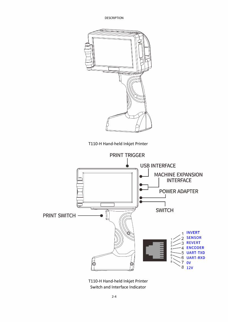
T110-H Hand-held Inkjet Printer
T110-H Hand-held Inkjet Printer
Switch and Interface Indicator

DESCRIPTION
2-5
T110-H Hand-held Inkjet Printer Composition Schematic

DESCRIPTION
2-6
T110 For Production Line(with 1pc Ink Cartridge)
T110 For Production Line(with 1pc Ink Cartridge) and Interface Schematic

DESCRIPTION
2-7
T210 For Production Line(with 2pc Ink Cartridge)
T210 For Production Line(with 2pc Ink Cartridge)

DESCRIPTION
2-8
T210 Fo
r Pro
du
ction
Line(w
ith 2p
c Ink C
artridge)
and
Interface Sch
ematic

DESCRIPTION
2-9
PRINTER SPECIFICATION
T110-H Hand-held Inkjet Printer
Nozzle
Parameters
Nozzle Type Thermal foamable head TIJ2.5
Printing Accuracy 150DPI / 300DPI / 600DPI
Print Height The minimum print 1mm / maximum print height
12.7mm
Printing From Best print from 2-5mm
Print Content
Multi-language character / dynamic
two-dimensional code / barcode / images / serial
number / date / counter / variable dynamic
database / RS232 receive real-time data printing
Printing Material
Cardboard / plastic / metal / plate / pipe / stone /
cable / electronic components / auto parts /
industrial chemical packaging / pharmaceutical
food gift boxes
Ink Type Aqueous / solvent and 42ml cartridge CISS
Ink Color Black / white / red / yellow / blue / green / stealth /
UV
Cartridge Chip Contactless chip RFID tags, automatic identification
and recording ink of the ink remaining parameters
Machine
Parameters
Operating System Embedded Linux operating system
The Main Hardware
American TI AM3358 industrial-grade CPU / USA
Xilinx Spant6 industrial-grade FPGA / TIJ dedicated
ASIC chip
Communication
Interface USB / RS232
External Interface Photocell / encoder / reverse inverting control
Supported Languages
Multi-language (Chinese / English / Arabic / Danish
/ German / Russian / French / Finnish / Korean /
Norwegian / Portuguese / Japanese / Spanish /
Italian etc ...)
Battery Parameters 12.6V / 3350mAh lithium batteries (lithium
batteries detachably supporting a single)
Power Parameters 100-240V AC input / 12.6V 3A DC output
Machine Materials ABS + PC + Metal
Machine
Specifications 230mm*137mm*97mm
Working Environment Temperature of 0-45 ° C / humidity of 30-70% Rh

DESCRIPTION
2-10
T110 For Production Line
Nozzle
Parameters
Nozzle Type Thermal foamable head TIJ2.5
Printing Accuracy 150DPI / 300DPI / 600DPI
Print Height The minimum print 1mm / maximum print height
12.7mm
Printing From Best print from 2-5mm
Print Content
Multi-language character / dynamic
two-dimensional code / barcode / images / serial
number / date / counter / variable dynamic
database / RS232 receive real-time data printing
Printing Material
Cardboard / plastic / metal / plate / pipe / stone /
cable / electronic components / auto parts /
industrial chemical packaging / pharmaceutical
food gift boxes
Ink Type Aqueous / solvent and 42ml cartridge CISS
Ink Color Black / white / red / yellow / blue / green / stealth
/ UV
Cartridge Chip Contactless chip RFID tags, automatic identification
and recording ink of the ink remaining parameters
Machine
Parameters
Operating System Embedded Linux operating system
The Main Hardware
American TI AM3358 industrial-grade CPU / USA
Xilinx Spant6 industrial-grade FPGA / TIJ dedicated
ASIC chip
Communication
Interface USB / RS232
External Interface Photocell / encoder / reverse inverting control
Supported Languages
Multi-language (Chinese / English / Arabic / Danish
/ German / Russian / French / Finnish / Korean /
Norwegian / Portuguese / Japanese / Spanish /
Italian etc ...)
Power Parameters 100-240V AC input / 12.6V 3A DC output
Machine Materials Aerospace aluminum
Machine
Specifications 138mm*87mm*60mm
Working Environment Temperature of 0-45 ° C / humidity of 30-70% Rh
T210 For Production Line

DESCRIPTION
2-11
Nozzle
Parameters
Nozzle Type Thermally foamable head TIJ2.5
Printing Accuracy 150DPI / 300DPI / 600DPI
Print Height The minimum print 1mm / single-nozzle print
height 12.7mm / 25.4mm maximum print height
Printing From Best print from 2-5mm
Print Content
Multi-language character / dynamic
two-dimensional code / barcode / images / serial
number / date / counter / variable dynamic
database / RS232 receive real-time data printing
Printing Material
Cardboard / plastic / metal / plate / pipe / stone /
cable / electronic components / auto parts /
industrial chemical packaging / pharmaceutical
food gift boxes
Ink Type Aqueous / solvent and 42ml cartridge CISS
Ink Color Black / white / red / yellow / blue / green / stealth
/ UV
Cartridge Chip Contactless chip RFID tags, automatic identification
and recording ink of the ink remaining parameters
Machine
Parameters
operating System Embedded Linux operating system
The Main Hardware
American TI AM3358 industrial-grade CPU / USA
Xilinx Spant6 industrial-grade FPGA / TIJ dedicated
ASIC chip
Communication
Interface The network interface / USB / RS232
External Interface
Photocell / encoder / reverse inverting control /
alarm output / output serial number / serial
number External Reset / Update Serial No. outer /
external print information selecting / nozzle head
attachment connected to 1-2 / install separate
nozzle / nozzles may be spliced bis / double nozzle
may be individually isolated (1.8 m cable links)
Supported languages
Multi-language (Chinese / English / Arabic / Danish
/ German / Russian / French / Finnish / Korean /
Norwegian / Portuguese / Japanese / Spanish /
Italian etc ...)
Power Parameters Input 100-240V AC / 30V 4A DC output
Machine Materials Industry standard stainless steel
Machine
Specifications
Host 202mm * 119mm * 61.2mm / nozzle set
112mm * 79mm * 103mm
Working Environment Temperature of 0-45 ° C / humidity of 30-70% Rh
T110/T210 BASIC PRINCIPLE OF PRINTING

DESCRIPTION
2-12
The T110/T210 adopts the thermal foaming nozzle inkjet principle (TIJ), and
the thermal foaming nozzle adopts a heating resistor component and is mounted
on the nozzle.Side wall. By applying a very short electrical pulse (1-10 μs) to the
heating resistor, a very high heat flux can be produced. The heating temperature
is about 270 degrees, and the ink quickly overheats and reaches the thermal
limit to form evaporating bubbles. The high pressure inside the bubble causes
the bubble to grow rapidly and squeeze the ink. Due to the influence of the
surface tension of the nozzle to form an ink droplet, as the temperature inside
the bubble decreases, the pressure decreases, and the bubble begins to rupture.
The ink droplet is ejected from the nozzle due to inertia. After the heating
resistor is cooled, the bubble disappears, and the attraction force generated
when the bubble is broken attracts the new ink from the storage ink cartridge to
the nozzle to prepare for the next ink absorption.
The inkjet process of a nozzle is roughly divided into five parts:
(1) Heating: The side of the nozzle is provided with a heating resistor
element. Under non-operating conditions, the tension in the nozzle is
balanced with the external atmospheric pressure. When an electric
pulse is applied to the heating resistor, the temperature of the nearby
ink rises rapidly to form a superheated layer.
(2) Bubble Growth: Continuous heating, vaporization of the superheated
layer causes bubbles to form near the heating resistor. As the ink rapidly
vaporizes, the microbubbles become larger to form a vapor film, and the
film has a heat insulating effect to prevent heating of all the ink in the
nozzle.
(3) Drop Ejection: At this time, the electric pulse disappears, and the
surface temperature of the heating resistor starts to decrease, but the
residual heat causes the bubble to further expand, expands to the
maximum, and the ink is extruded.
(4) Bubble Collapse: As the surface temperature of the heating resistor
continues to decrease, the bubble begins to shrink, causing the pressure
of the nozzle to decrease, sucking the ink into the nozzle, and separating
the ink droplets.
(5) Refill: The bubble is further shrunk, the pressure outside the nozzle is
greater than the internal pressure, the bubble completely disappears,
and the ink in the nozzle is replenished.
OPERATION
3-1
PART 3:SCREEN DESCRIPTION
CONTENTS
SCREEN LOCK............................................................................................................. 2
INFORMATION EDITING MENU (1) ............................................................................. 3
INFORMATION EDITING MENU (2) ............................................................................. 3
INSERT TEXT ...................................................................................................... 4
OTHER PROPERTIES............................................................................................ 5
INSERT CLOCK .................................................................................................... 6
SERIAL NUMBER ................................................................................................ 7
INSERT 2D CODE ................................................................................................ 8
INSERT BARCODE ............................................................................................... 9
INSERT LOGO ................................................................................................... 10
INSERT SHIFT ................................................................................................... 11
INSERT VARIABLE ............................................................................................. 12
SERIAL DATA..................................................................................................... 13
FILE STORAGE .......................................................................................................... 14
MESSAGE SAVE ................................................................................................ 15
PRINT PARAMETERS ................................................................................................ 16
Delay Word Width ........................................................................................... 16
Invert Reverse .................................................................................................. 19
DYNAMIC SETTING ........................................................................................... 20
Repeat Print ..................................................................................................... 21
SERIAL NUMBER CONTROL .............................................................................. 22
CARTRIDGE PARAMETERS ................................................................................ 23
MECHANICAL PARAMETER (1) ................................................................................. 24
MECHANICAL PARAMETER (2) ................................................................................. 24
DATE FORMAT .................................................................................................. 25
TIME FORMAT .................................................................................................. 26
MONTH CODE .................................................................................................. 27
WEEK CODE ..................................................................................................... 28
HOUR CODE ..................................................................................................... 29
PRODUCT COUNT ............................................................................................ 30
SYSTEM SETTING ............................................................................................. 31
Screen Adjust ................................................................................................... 32
SERVICE MENU ........................................................................................................ 33
SYSTEM SETTING ............................................................................................. 34
CREATE USER ................................................................................................... 35
Event Record .................................................................................................... 36

OPERATION
3-2
SCREEN LOCK
After pressing the printer power button for about three seconds, the green light will
illuminate and release, and a screen similar to the one shown in the figure will
appear. Enter the password by pressing the unlock button directly below the screen
to enter the main menu area.
Entering the specified password screen below the small lock will be unlocked. Click
on the main menu button at the top left of the screen to enter the main menu area.
OPERATION
3-3
INFORMATION EDITING MENU (1)
INFORMATION EDITING MENU (2)
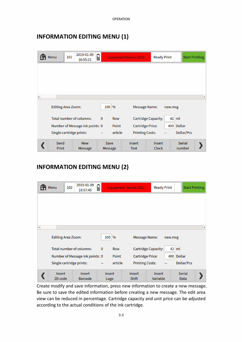
Create modify and save information, press new information to create a new message.
Be sure to save the edited information before creating a new message. The edit area
view can be reduced in percentage. Cartridge capacity and unit price can be adjusted
according to the actual conditions of the ink cartridge.

OPERATION
3-4
INSERT TEXT
Insert information the user needs to print, and user can adjust the font size required.
The font size range is controlled within the maximum print range. Note that the
printed information will be incompletely displayed beyond the editing area. You can
move the position of the text through the touch screen or precisely position it
through the X-axis and Y-axis positions. Clicking on any information in the editing
area can be traced back to the corresponding information editing menu.
After clicking "text", a small keyboard will pop up. The "&123" button in the lower

OPERATION
3-5
left corner of the keypad can insert numbers and symbols, and the small arrow
switches between upper and lower case. The T110 printer keyboard input method is
common.
OTHER PROPERTIES
The other property settings for information editing in the main menu are similar.
Other properties will appear in the Edit menu area. Other properties can be selected
according to user needs.
Font: Select different fonts according to your needs, File Storage → Font
Save to manage the fonts in the printer.
Direction: Set the direction of the font (90°, 180°, 270° rotation).
Space: Adjust the spacing between fonts within the text (1, 2, 3, 4, 5).
Font Size: Adjust the size of the added text font.
X, Y-axis: The position of the text can be moved by the touch screen or accurately
positioned by the X-axis and Y-axis positions.
Function key options:
Return The set options are not saved.
OK Save the set options.

OPERATION
3-6
INSERT CLOCK
Date or Time can be inserted in the message. Time or Date format and offset values
can be set from options, The date/time format can be edited and added as needed.
(see page 23/24).
Clock content: The small triangle slide menu has two options to choose from,
including date and Time.
Date format: Can be set in yyyyMMdd, yyMMdd, ddMMyyyy, ddMMyy format.
Time format: Can be set in hh:mm:ss, hh:mm, hhmmss, mmss, ss format.
Date Offset: A clock (date) that can be derived from the main clock (date) content.

OPERATION
3-7
Font Size: Adjust the date/time font size that has been added.
X, Y-axis position: The position of the text can be moved by the touch screen or
accurately positioned by the X-axis and Y-axis positions.
Function key options:
Return Does not enter the Insert Clock Contents menu to return to the
previous menu.
OK Enter the clock information in the message.
Delete Delete the Data/Time information.
Other properties Insert clock font, orientation, spacing formatting. (see page 5)
SERIAL NUMBER
You can create a serial numbering system and insert the system into the information.
The sequence number whose limit value 1 is greater than the limit value 2 will be
incremented sequentially, contrary that decreases. The serial number can be
updated after resetting within the Print Parameter → Serial Number Control or by
specifying a value. (see page 20)
Serial Number: The created serial number is numbered. The T110 printer can have 4
serial numbers.
Limit 1: The starting value of the serial number.
Limit 2: The end value of the serial number.
Step Size:Step size between successive numbers.
Repeat Count: Number of times serial number is to be repeated before stepping to
the next value.
Leading Zeros: Select Yes/No for leading number positions to be zeros or blank
Font size: Adjust the serial number font size as needed.

OPERATION
3-8
X, Y-axis position: The position of the text can be moved by the touch screen or
accurately positioned by the X-axis and Y-axis positions.
Function key options:
Returns Return the previous menu without inserting a sequence number.
OK Insert a sequence number into the message.
Delete Delete the serial number information.
Other properties Insert the serial number font, orientation, and spacing formatting.
(see page 5)
INSERT 2D CODE
Select a QRcode or DataMatrix code in the barcode type and insert it in the text
message. Edit the information in the inserted content to generate the corresponding
QRcode or DataMatrix code.
Barcode Type: Select QRcode or DataMatrix code.
X, Y-axis position: The position of the text can be moved by the touch screen or
accurately positioned by the X-axis and Y-axis positions.
Inserts: Insert text, time, serial number, shift, file, serial data and other information
content, If you need a QR code such as WeChat or website, you cannot enter the
content through the QR code. You can only insert the corresponding QR code by
inserting the image.
Size: Size of the inserted 2D code. Exceeding the maximum print range, the printout
will be incomplete.
Direction: Set the direction of the 2D code (90°, 180°, 270° rotation).
Border Size: The size of the red border outside the 2D code.
Inverse: A contrast color is formed with the color of the inserted 2Dcode.

OPERATION
3-9
Fault Tolerance: The ability of the 2D code to be scanned after it is occluded. The
higher the fault tolerance rate, the more parts the 2D code can be occluded. The
fault tolerance are divided into: L, M, Q, H. level.
Function key options:
Return Returns to the previous menu without entering the 2D code.
OK Insert a 2D code into the message.
Delete Delete the 2D code information.
INSERT BARCODE
EAN13/8 code, CODE128/39 code or UPCA/E code can be selected in the barcode
type and inserted in the text message. The information is edited in the inserted
content to generate a corresponding EAN 13/8 code, CODE 128/39 code or UPCA/E
code.
Barcode Type: EAN13/8 code, CODE128/39 code or UPCA/E code。
X, Y-axis position: The position of the text can be moved by the touch screen or
accurately positioned by the X-axis and Y-axis positions.
Insert: Insert text, time, serial number, shift, file, serial data and other information
content,If you need to insert special content into the barcode, you cannot enter the
content through the barcode. You can only insert the corresponding barcode by
inserting the image.
Size: Size of the inserted barcode. Exceeding the maximum print range, the printout
will be incomplete.
Direction: Set the direction of the barcode (90°, 180°, 270° rotation).
Border Size: The size of the red border outside the barcode.
Inverse: A contrast color is formed with the color of the inserted barcode.

OPERATION
3-10
Function key options:
Return Returns to the previous menu without entering the barcode.
OK Insert a barcode into the message.
Delete Delete the barcode information.
INSERT LOGO
Select a logo in the logo save and insert it in the text message. Printing is incomplete
beyond the editing area.
File Source: The small triangle slide menu has two options to choose from, including
local files and U disk files.
Select File: Find the corresponding logo name in the local file or U disk file to insert
the logo.
Inverse: A contrast color is formed with the color of the inserted logo.
Height: The height of the inserted logo. Logo height cannot be changed.
Width: The width of the inserted logo. Logo width cannot be changed.
Direction: Set the direction of the picture (90°, 180°, 270° rotation).
X, Y-axis position: The position of the text can be moved by the touch screen or
accurately positioned by the X-axis and Y-axis positions.
Function key options:
Return Returns to the previous menu without entering the logo.
OK Insert a logo into the message.
Delete Delete the logo information.

OPERATION
3-11
INSERT SHIFT
Create shift code information and increase or decrease shifts.
Shift code: You can enter the shift code according to the user's needs. (name and
identification number, etc.).
Start time: Enter the hour and minute of the start time in the format of a 24-hour
clock system.
End time: Enter the hour and minute of the end time in the format of a 24-hour clock
system.
Function key options:
Return Returns to the previous menu without entering the shift code.
OK Enter the shift code in the message.
Delete Deletes shift code information.
Increase shifts Spawn more shifts to the shift code you create.
Reduce shifts Deductions for derivative shifts.
Other properties Insert shift font, orientation, spacing formatting. (see page 5)

OPERATION
3-12
INSERT VARIABLE
The .TXT (text file, tab delimited) or .CSV (comma separated) documents specified in
the local or U disk file can be printed in sequence.
.TXT/.CSV document production: Create a new Microsoft Office Excel worksheet and
enter the content you want to print in the form. Each column is distinguished and
saved as a specified .TXT (text file, tab delimited) or .CSV (comma separated)
document.
File Source: The small triangle slide menu has two options to choose from, including
local files and U disk files.
Select file: Find the corresponding variable name in the local file or U disk file to
insert the variable.
Current Row: The first item of the current print column, the number of items of
attention cannot exceed the total number of items.
Start Row: The current print column starts printing from that item, and the number
of items must not exceed the total number of items.
Total Row: How many items are added to the current print column.
Select Column: Select the first few columns of the current variable to print.
End Row: The current print column ends printing from that item, and the number of
items must not exceed the total number of items.
Total Columns: How many columns are added to the current variable.
Partition length: The length of the current variable print area, which can be adjusted
according to the length of the text in the document.
Repeat printing: whether to use the repeat printing function, you can choose yes or
no
Repeat Times: The number of times the variable being printed is printed repeatedly
before starting to print the next variable.
OPERATION
3-13
Function key options:
Cancel Return to the previous menu without entering the shift code
OK Enter the shift code in the message
Delete Deletes shift code information
More Properties Shift property menu settings format (see page 5)
SERIAL DATA
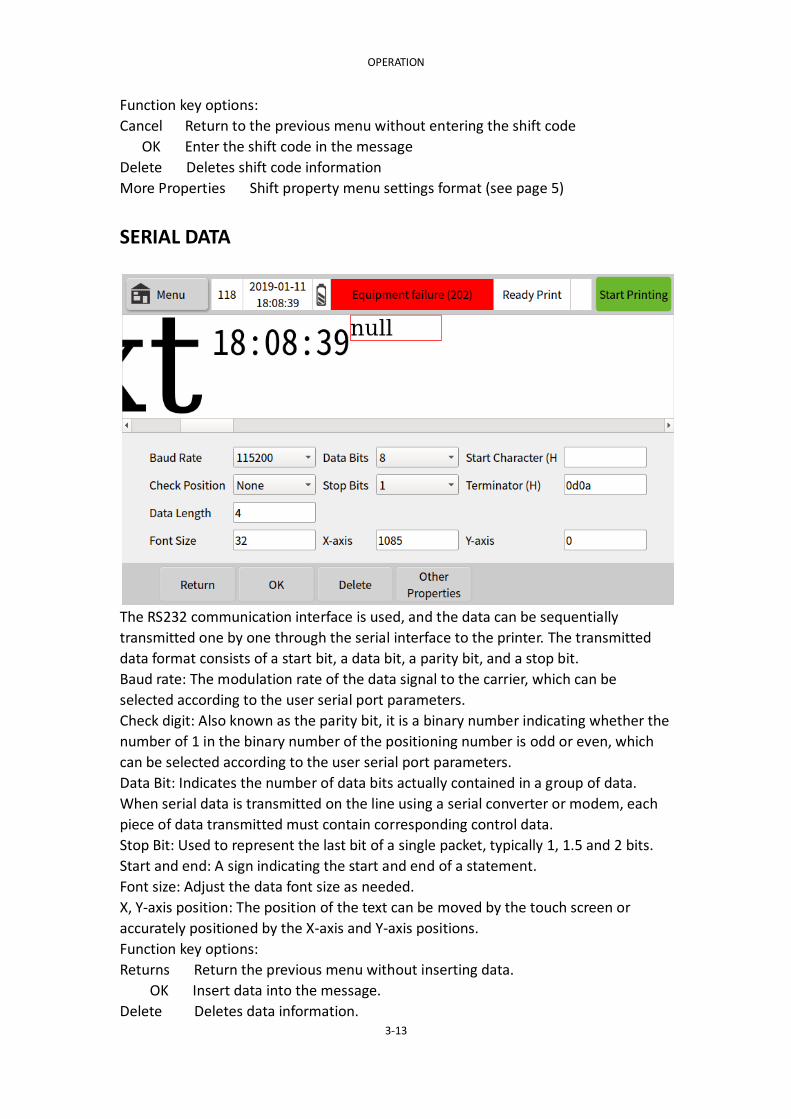
The RS232 communication interface is used, and the data can be sequentially
transmitted one by one through the serial interface to the printer. The transmitted
data format consists of a start bit, a data bit, a parity bit, and a stop bit.
Baud rate: The modulation rate of the data signal to the carrier, which can be
selected according to the user serial port parameters.
Check digit: Also known as the parity bit, it is a binary number indicating whether the
number of 1 in the binary number of the positioning number is odd or even, which
can be selected according to the user serial port parameters.
Data Bit: Indicates the number of data bits actually contained in a group of data.
When serial data is transmitted on the line using a serial converter or modem, each
piece of data transmitted must contain corresponding control data.
Stop Bit: Used to represent the last bit of a single packet, typically 1, 1.5 and 2 bits.
Start and end: A sign indicating the start and end of a statement.
Font size: Adjust the data font size as needed.
X, Y-axis position: The position of the text can be moved by the touch screen or
accurately positioned by the X-axis and Y-axis positions.
Function key options:
Returns Return the previous menu without inserting data.
OK Insert data into the message.
Delete Deletes data information.

OPERATION
3-14
Other properties Insert data font, orientation, spacing formatting. (see page 5)
FILE STORAGE
In the main menu file management, the information, pattern, font and data of the
printer can be managed. The main interface of the file management will display the
status information of the current printer storage space, wherein the information file
format supports .msg, pattern file. The format supports .bmp, the font file format
supports .ttf or .fon, the data file supports .txt or .csv format, and the printer
contains 256MB of storage space.

OPERATION
3-15
MESSAGE SAVE
The information storage in the file management can edit and manage the
information files stored in the printer. Pattern storage, font storage, data file function
key options refer to information storage instructions.
Function key options:
Cancel Returns to the previous menu without entering the information store.
Select Message After selecting the information to be printed, click on the
selected information to print the selected information, and only one file can be
selected at a time.
Delete After selecting the information you want to delete, click Delete to
delete the selected information, and you can choose to delete multiple files each
time.
Import After inserting the USB to the corresponding interface of the printer,
the information in the USB device can be imported into the printer.
Export After inserting the USB to the corresponding interface of the printer,
you can export the information in the printer to the USB device.

OPERATION
3-16
PRINT PARAMETERS
In the main menu printing parameters, the printing parameters of all the information
in the printer can be adjusted. The printing parameters are common settings, and all
the information is valid. The main interface of the printing parameters will display the
information of the current printing parameters after the printer is adjusted.
Delay Word Width
Source and internal rate generation source description
When the rate generation source is internal:

OPERATION
3-17
Control internal and external interfaces (product detector and rate generation
source), word width and delay. The rate generation source can be directly selected as
internal or external (the peripheral is typically a rotary encoder). Encoder selection
and external word width settings are not available when the rate generation source is
internal.When the stroke rate generation source is external, the internal word width
setting is not available, and the print delay column number and the light eye level
parameter are shared.
Stroke Source: Select internal/external ------ external is a rotary encoder.
Internal Width: When the stroke rate generation source is internal, the setting word
width is in the range of 1-12000 columns/second.
Print Delay: Enter the delay (in number of columns) between the start of the print
input signal and the first sequence of print information. Each print format has a
minimum delay value, and the set value must not be lower than this minimum. 光眼
Trigger Level: High/low level can be selected.
Current Level: Displays the current eye level status.
Function key options:
Cancel Abandon the changes and return to the previous screen.
OK Modify the settings to return to the previous screen.
OPERATION
3-18
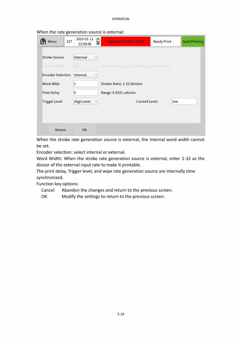
When the rate generation source is external:
When the stroke rate generation source is external, the internal word width cannot
be set.
Encoder selection: select internal or external.
Word Width: When the stroke rate generation source is external, enter 1-32 as the
divisor of the external input rate to make it printable.
The print delay, Trigger level, and wipe rate generation source are internally time
synchronized.
Function key options:
Cancel Abandon the changes and return to the previous screen.
OK Modify the settings to return to the previous screen.

OPERATION
3-19
Invert Reverse
Invert or reverse each message. This option will be applied to all information unless
dynamic control is used. If dynamic control is used, you can set the number of times
to flip or reverse the print.
Reverse Control:You can choose to turn it on or off, and use it for all information.
Invese Control:You can choose to turn it on or off, and use it for all information.
Function key options:
Cancel Abandon the changes and return to the previous screen.
OK Modify the settings to return to the previous screen.

OPERATION
3-20
DYNAMIC SETTING
Set the number of times a piece of information needs to be flipped or reversed. The
number of times can be set by "repeat print" as described below.
Reverse dynamic control: optional Close, Message control, Product control, External
control.
Message Control: Set the initial direction and number of repetitions of flipping or
reversing the print according to the amount of information.
Product Control: The initial direction and number of prints of the reverse printing can
be set according to the number of product inspections.
External Control: You can enter external control print settings to flip or reverse the
print.
Invese dynamic control settings can refer to the Reverse dynamic control.
Function key options:
Cancel Abandon the changes and return to the previous screen.
OK Modify the settings to return to the previous screen.
OPERATION
3-21
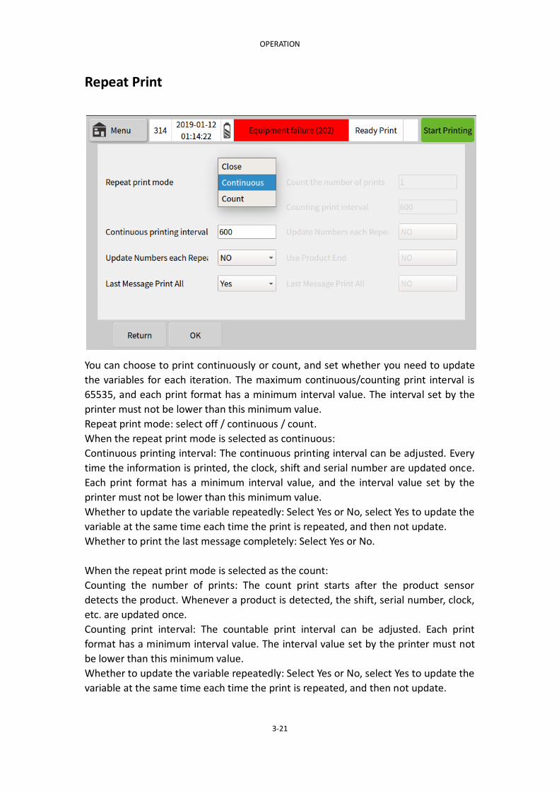
Repeat Print
You can choose to print continuously or count, and set whether you need to update
the variables for each iteration. The maximum continuous/counting print interval is
65535, and each print format has a minimum interval value. The interval set by the
printer must not be lower than this minimum value.
Repeat print mode: select off / continuous / count.
When the repeat print mode is selected as continuous:
Continuous printing interval: The continuous printing interval can be adjusted. Every
time the information is printed, the clock, shift and serial number are updated once.
Each print format has a minimum interval value, and the interval value set by the
printer must not be lower than this minimum value.
Whether to update the variable repeatedly: Select Yes or No, select Yes to update the
variable at the same time each time the print is repeated, and then not update.
Whether to print the last message completely: Select Yes or No.
When the repeat print mode is selected as the count:
Counting the number of prints: The count print starts after the product sensor
detects the product. Whenever a product is detected, the shift, serial number, clock,
etc. are updated once.
Counting print interval: The countable print interval can be adjusted. Each print
format has a minimum interval value. The interval value set by the printer must not
be lower than this minimum value.
Whether to update the variable repeatedly: Select Yes or No, select Yes to update the
variable at the same time each time the print is repeated, and then not update.

OPERATION
3-22
Whether to use the product end signal: Use Yes/No to select whether to stop the
repeat when the product is detected.
Function key options:
Cancel Abandon the changes and return to the previous screen.
OK Modify the settings to return to the previous screen.
SERIAL NUMBER CONTROL
Editable information editing → Insert the serial number in the serial number, reset
the current serial number or specify a value and update it. (The serial number has
and can only exist 4)
No. 1/2/3/4: Click on the value to modify it, click Update to set the sequence number
to the updated value, and reset to reset the current serial number to the limit value
of 1.
Whether the serial number stops stepping during the fault: You can choose yes or no.
Function key options:
Cancel Abandon the changes and return to the previous screen.
OK Modify the settings to return to the previous screen.
OPERATION
3-23
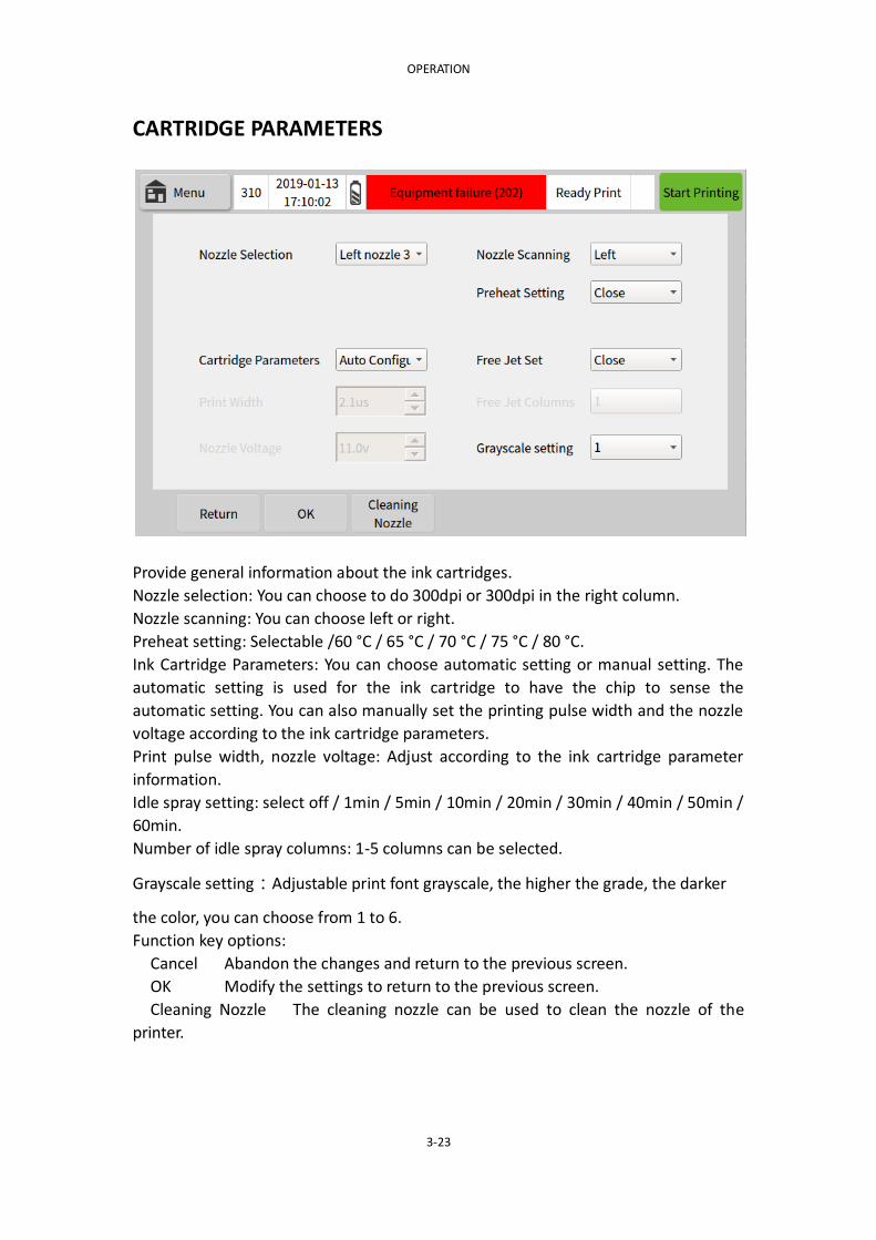
CARTRIDGE PARAMETERS
Provide general information about the ink cartridges.
Nozzle selection: You can choose to do 300dpi or 300dpi in the right column.
Nozzle scanning: You can choose left or right.
Preheat setting: Selectable /60 °C / 65 °C / 70 °C / 75 °C / 80 °C.
Ink Cartridge Parameters: You can choose automatic setting or manual setting. The
automatic setting is used for the ink cartridge to have the chip to sense the
automatic setting. You can also manually set the printing pulse width and the nozzle
voltage according to the ink cartridge parameters.
Print pulse width, nozzle voltage: Adjust according to the ink cartridge parameter
information.
Idle spray setting: select off / 1min / 5min / 10min / 20min / 30min / 40min / 50min /
60min.
Number of idle spray columns: 1-5 columns can be selected.
Grayscale setting:Adjustable print font grayscale, the higher the grade, the darker
the color, you can choose from 1 to 6.
Function key options:
Cancel Abandon the changes and return to the previous screen.
OK Modify the settings to return to the previous screen.
Cleaning Nozzle The cleaning nozzle can be used to clean the nozzle of the
printer.

OPERATION
3-24
MECHANICAL PARAMETER (1)
MECHANICAL PARAMETER (2)
It is used to modify the format of the printer and adjust the mechanical parameters
of all information in the printer. The mechanical parameters are common settings
and are valid for all information. The main interface of the mechanical parameters

OPERATION
3-25
will display the current printer cartridge model, margin, effective date, drive voltage
and print pulse width.
DATE FORMAT
Date formats in memory can be added, added or deleted. The new date format can
be used in Information Editing → Insert Clock. (see page 6)
Create a new format: Select to create a new date format in the year variable / month
variable / week variable / day variable / delimiter, Click on the two undersizes to
delete the variable, edit the new date format and click Add to create a new date
format.
Function key options:
Cancel Returns to the previous screen.
OK Add a new date format and return to the previous screen.
Delete Deletes the date format in memory.
OPERATION
3-26
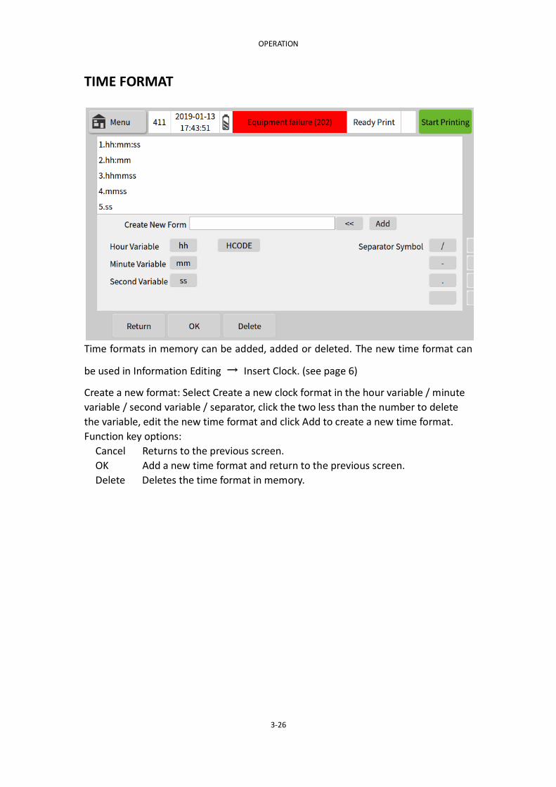
TIME FORMAT
Time formats in memory can be added, added or deleted. The new time format can
be used in Information Editing → Insert Clock. (see page 6)
Create a new format: Select Create a new clock format in the hour variable / minute
variable / second variable / separator, click the two less than the number to delete
the variable, edit the new time format and click Add to create a new time format.
Function key options:
Cancel Returns to the previous screen.
OK Add a new time format and return to the previous screen.
Delete Deletes the time format in memory.

OPERATION
3-27
MONTH CODE
The month name can be modified to be used when inserting the clock function when
editing information.
January, February...December: Enter up to 3 numbers and alphabetic characters.
Function key options:
Cancel Abandon the modification.
Saving current settings Use the new settings in the current information.
Save as default Leave a new name for the new information.
Use default values Use the default name in the message.

OPERATION
3-28
WEEK CODE
The day of the week name can be modified for use when inserting the clock function
when editing information.
Monday, Tuesday... Friday: Enter up to 3 numbers and alphabetic characters.
Function key options:
Cancel Abandon the modification.
Saving current settings Use the new settings in the current information.
Save as default Leave a new name for the new information.
Use default values Use the default name in the message.

OPERATION
3-29
HOUR CODE
An alphanumeric character can be associated with each 24 hour, and the insertion
clock can be used to insert these characters into the message.
0:00, 1 hour...23: Enter up to 3 numbers and alphabetic characters.
Function key options:
Cancel Abandon the modification.
Saving current settings Use the new settings in the current information.
Save as default Leave a new name for the new information.
Use default values Use the default name in the message.
。
OPERATION
3-30
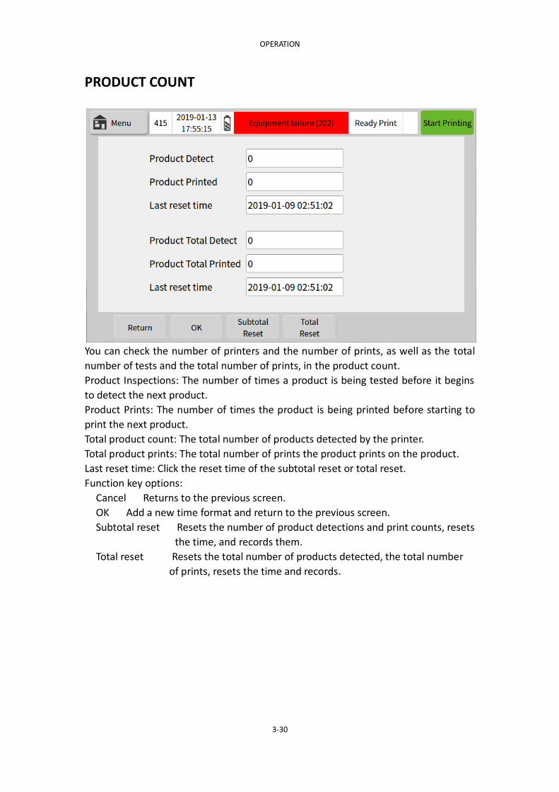
PRODUCT COUNT
You can check the number of printers and the number of prints, as well as the total
number of tests and the total number of prints, in the product count.
Product Inspections: The number of times a product is being tested before it begins
to detect the next product.
Product Prints: The number of times the product is being printed before starting to
print the next product.
Total product count: The total number of products detected by the printer.
Total product prints: The total number of prints the product prints on the product.
Last reset time: Click the reset time of the subtotal reset or total reset.
Function key options:
Cancel Returns to the previous screen.
OK Add a new time format and return to the previous screen.
Subtotal reset Resets the number of product detections and print counts, resets
the time, and records them.
Total reset Resets the total number of products detected, the total number
of prints, resets the time and records.

OPERATION
3-31
SYSTEM SETTING
Set the system time, button language, screen saver and other settings in the printer.
System time: Please refer to the Beijing time setting.
Button sound: Select to turn it on or off.
Print Trigger Sound: Select On or Off.
Print end sound: Select to turn it on or off.
Screen saver settings: Select to turn it on or off.
Function key options:
Cancel Returns to the previous screen.
OK Add a new time format and return to the previous screen.

OPERATION
3-32
Screen Adjust
The printer uses a 5.0-inch color industrial-grade resistive touch screen. The
resistance screen has different resistances due to the contact between the two layers
of the screen at different locations. The resistance of the different resistor screens
will be slightly different.
After screen calibration is selected, the system will automatically enter the 5-point
touch screen calibration process. Click on the five calibration cross positions in the
upper left, upper right, lower left and middle of the screen to complete screen
calibration. Click on the confirmation to save the calibration status, cancel or 10
seconds without clicking on the confirmation to restore the pre-calibration status by
default.
OPERATION
3-33
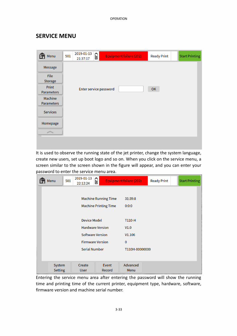
SERVICE MENU
It is used to observe the running state of the jet printer, change the system language,
create new users, set up boot logo and so on. When you click on the service menu, a
screen similar to the screen shown in the figure will appear, and you can enter your
password to enter the service menu area.
Entering the service menu area after entering the password will show the running
time and printing time of the current printer, equipment type, hardware, software,
firmware version and machine serial number.
OPERATION
3-34
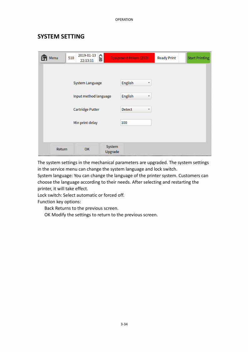
SYSTEM SETTING
The system settings in the mechanical parameters are upgraded. The system settings
in the service menu can change the system language and lock switch.
System language: You can change the language of the printer system. Customers can
choose the language according to their needs. After selecting and restarting the
printer, it will take effect.
Lock switch: Select automatic or forced off.
Function key options:
Back Returns to the previous screen.
OK Modify the settings to return to the previous screen.

OPERATION
3-35
CREATE USER
It is used to add or delete printer users. Each user has a corresponding user name
and password. After adding a user, you can select login to switch users on the home
page.
Function key options:
Cancel Returns to the previous screen
Delete Enter the user name and user password and delete to delete the user.
Add User Enter User Name and User Password and click OK to add user

OPERATION
3-36
Event Record
It is used to record the running status of the printer machine.
Function key options:
Back Returns to the previous screen
OK Modify settings to return to the previous screen

OPERATION
4-1
PART 4:OPERATION
CONTENTS
PART 4:OPERATION ................................................................................................... 1
START-UP ........................................................................................................... 2
SHUT DOWN ...................................................................................................... 2
REPLACE THE INK TANK ...................................................................................... 2
CREATE INFORMATION ....................................................................................... 3
Print information........................................................................................ 3
Save information ........................................................................................ 4
Select information from memory ............................................................... 4
Insert clock ................................................................................................ 4
Insert serial number ................................................................................... 5
INSERT 2D CODE ........................................................................................ 5
Insert barcode (not perfect) ....................................................................... 6
INSERT LOGO ............................................................................................. 6
INSERT SHIFT .............................................................................................. 6
Insert variable ............................................................................................ 7
Serial data .................................................................................................. 8

OPERATION
4-2
START-UP
Press the button switch on the upper side of the printer screen
Note: (1) There is a reminder light next to the online (handheld) power adapter
interface, which needs to be lit red to prove that there is power input.
(2) After pressing the switch for about three seconds, the green light will be on
and it will be released. The boot process takes about 20 seconds.
The boot screen displays the CODPAD logo and prohibits the insertion and removal of
the cartridge in the print state.
Enter the main interface, the status bar displays "Device normal", "No print
data" and other information.
Enter the password by pressing the unlock button directly below the screen to
enter the main menu area.
Create a new message in the information editing or in the file management →
information storage, select the information that the user needs to print, and click
Send.
Note: Do not insert or remove cartridges in the print state
The print is sent before starting the print, otherwise the start print button is
grayed out.
The print status bar displays information such as "Device OK", "Ready to print",
and so on.
The printer is ready to print information, click to start printing.
SHUT DOWN
Click the Stop Printing button in the upper right corner of the screen.
Note: The printer must be powered off before the printer is stopped.
Status bar displays information such as "Device OK", "Ready print", and so on.
If it does not print for more than 30 minutes, please remove the ink cartridge
and cover the nozzle protection cover.
Press the button switch on the top of the printer screen to turn off the printer.
REPLACE THE INK TANK
When the capacity of the ink cartridge is too low, the screen will display
information such as "low ink cartridge remaining" and "ink cartridge is empty".
When the ink cartridge capacity is empty, the printer will not continue printing.
Follow the steps below to replace the ink tank.
Note: The printer main power must be turned off according to the shutdown
procedure before replacing the ink tank.
Install the ink tank (as shown on the next page).
Loosen the clamp block of the ink tank in the direction shown, and release the

OPERATION
4-3
clamp block horizontally onto the ink tank slot. After aligning the ink cartridge
with the pinhole card slot, gently press the position of the ink cartridge by hand
to fasten the compression block. Remove the ink tank
Fix the ink cartridge with one hand and release the cartridge buckle with the
other hand. Place the buckle horizontally on the ink slot, hold the protruding
part of the ink cartridge, and gently remove the ink cartridge.
CREATE INFORMATION
The following describes how to create a print. The user can use our suggested project
as an example. See Section 3: Screen Description for all displayed screens.
After booting and unlocking, in the main menu → Information Edit → New
Information.
Type information (such as abc123, etc.).
You can also type clock data, serial number, bar code, pattern, shift, variable, and
serial port data when creating details. The method of creating simple information will
be listed below.
Print information
(1) After selecting the information editing function, find the “New Information” in
the function key at the bottom of the screen.
(2) After editing the information and pressing “Send Print”, the screen display will
change from “No Print Data” to “Ready Printable” status, then the printer will print
the message once it receives the print signal.
OPERATION
4-4
Note: Regardless of the method used, if you modify a single message, you must press
the Send Print button again for the changes to take effect.
Save information
(1) After the new information has been edited, press the "Save Information" button.
(2) The box for entering the name of the message will pop up from the screen.
(3) Type the name of the information (such as "AAA").
(4) Select OK from the button options.
Select information from memory
(1) In the main menu file management information storage, you can call the edited
saved information.
(2) Select the information you want to print according to the name. A small tick will
appear when selected.
(3) Click on the selection information to print the selected information, and only one
file can be selected at a time.
(4) Click on Send Print in the message editing menu to print the message.
Follow the steps (1), (2), and (3) above to select the information you want to
delete and click Delete to delete the selected information. You can choose to
delete multiple files at a time.
Note: Information cannot be restored after it has been deleted.
Insert clock
(1) Insert the clock in the main menu information editing, and the clock content can
be selected as the date or time.
(2) Click the date/time format, select the desired date or clock format, and the
date/time format can be modified by yourself (see pages 3-23 and 3-24).
(3) Enter 0-24 hours to offset the current time;
Enter 0-365 days to offset the current date.
For example:The current time is 2018/10/01 00:00 (production date), you need
to insert a 2019/10/01 15:00 (shelf life), the shelf life is 1 year and 15 hours later
than the current time (production time), and For dates that require continuous
updates, we can make a 365-day offset on the date, with a time offset of 15
hours.
(4) Change the size of the clock/date font to the specified position of the text, and
the screen will change and display the clock.

OPERATION
4-5
Insert serial number
(1) Insert the serial number in the main menu information editing, and insert the
serial number into the print information.
(2) Each time a serial number is added, the serial number will be numbered by itself,
and the T110 printer can have 4 serial numbers. It can be updated according to the
serial number, after the print parameter → serial number control is reset or a
certain value is specified. (See pages 3-20)
(3) If the limit value 1 is greater than the limit value 2, the sequence number will be
incremented in order, that is, positive, and vice versa.
(4) If necessary, you can also set the number of times a certain serial number is
repeated before the update.
For example:Create sequence number 0000, 0001... until the end of 1000, the
step size is 1.
Limit 1:0000 Limit 2:1000 Step size:1
Repetitions: 0 Front position 0:Choose yes or no
INSERT 2D CODE
(1) Insert the QR code in the main menu information editing to insert the QR code
into the print information.
(2) The barcode type can be selected to generate QR code or DataMatrix code.
(3) The current barcode content is empty. You can click the "Insert Content"
drop-down box to select the new content.
If you need a QR code such as WeChat or website, you cannot enter the content
by QR code. You can only insert the corresponding QR code by inserting the
picture.
(4) If necessary, the reverse color can be selected to form a contrast color with the
color of the inserted QR code.
(5) The fault tolerance rate from low to high is L<M<Q<H respectively. After the
two-dimensional code is blocked, it can still be scanned out. The higher the fault
tolerance rate, the more the part of the two-dimensional code can be blocked. many
(6) The size of the two-dimensional code and the size of the outer frame can be
adjusted by itself.
(7) The direction in which the two-dimensional code is inserted can be set (90
degrees, 180 degrees, 270 degrees rotation).
Note that the red frame status will appear in the edit area beyond the print
range.

OPERATION
4-6
Insert barcode (not perfect)
(1) Insert barcode in the main menu information editing, and insert the barcode into
the print information.
(2) The barcode type can be selected to generate EAN13/8 code, CODE128/39 code
or UPCA/E code.
(3) The current barcode content is empty. You can click the "Insert Content"
drop-down box to select the new content.
If you need to insert a special barcode, you cannot enter the content through the
barcode. You can only insert the corresponding barcode by inserting the image.
(4) If necessary, you can choose the reverse color to form a contrast color with the
color of the inserted barcode.
(5) The size of the barcode and the size of the outer frame can be adjusted by itself.
(5) The direction in which the barcode is inserted can be set (90 degrees, 180
degrees, 270 degrees rotation).
Note that the red frame status will appear in the edit area beyond the print
range.
INSERT LOGO
(1) The insertion pattern in the main menu information editing can be inserted into
the print information.
(2) Pattern insertion can be performed in a local file or a U disk file.
The images in the printer can be managed in File Management → Pattern
Storage. (See pages 3-13)
(3) If necessary, the reverse color can be selected to form a contrast color with the
color of the inserted pattern.
(4) The direction of the insertion pattern can be set (90 degrees, 180 degrees, 270
degrees rotation).
Note: The red box status will appear in the edit area beyond the print range.
INSERT SHIFT
(1) The insertion shift in the main menu information editing can be inserted into the
print information.
(2) According to the start and end time (in hours and minutes according to the
24-hour clock system) and the shift code name.
(In the shift code column) enter up to 6 shift codes
(3) Determine from the options in the function key options. As long as the current
actual time is within the specified shift code start and end time range, and the shift
code name (such as "AAA") is inserted, the screen will change and display the

OPERATION
4-7
information.
For example:Starting at 07.30, ending at 15.30, code is AAA
Starting at 15.31, ending at 23.30, code is BBB
Starting at 23.30, ending at 07.29, code is CCC
Insert variable
(1) Insert variables in the main menu information editing to send variables to the
print information.
Variable format:
a computer new Microsoft Office Excel worksheet;
b Enter the content to be printed in the form, pay attention to distinguish each
column
* In the figure, column A represents a column and 111 represents a column.
c edited and saved as the specified .TXT (text file, tab delimited) or .CSV (comma
number Document
*Save as → other formats → save type as text file (tab delimited) or .CSV (comma
separated)
(2) Variable file insertion can be performed in a local file or a U disk file.
The variable files in the printer can be managed in the file management → data

OPERATION
4-8
file. (See pages 3-12)
(3) The coding machine generates the total number of items and the total number of
columns according to the contents of the read variable file.
(4) Select which item to start printing, and which item ends (no adjustment is
required in special cases).
(5) Select column to choose which column to print, the current item is which one to
print.
(6) Set the length of the print partition. (When the variable has a print message that
is too long, you need to adjust the partition length)
(7) If necessary, you can also set the number of times a variable is repeatedly printed
before updating.
For example, you need to print the first column of variables 111, 222, 333, 444,
555, 666, 777, 888, 999, 1100
The second column AAA, BBB, CCC, DDD, EEE, FFF, GGG, HHH, KKK, LLLL
a: At this point we need to create a new Microsoft Office Excel worksheet on the
computer, in the first column
Enter the corresponding value, enter the corresponding value in the second
column, and save it as .TXT (text file, system
Tab delimited or .CSV (comma separated) document, insert the prepared
document into the printer
USB interface, imported into the data file in file management.
b: Select the start item, end item and corresponding column, adjust the
partition length, and repeat printing.
Serial data
(1) In the serial port data in the main menu information editing, the serial port data
can be sent to the print information.
(2) The RS232 communication interface is used, one end is connected to the printer
and the other end is connected to the signal source.
(3) Select the corresponding baud rate, data bit, check bit, stop bit according to the
user serial port parameters.
(4) Input the start and end characters of the data to be transmitted. When the
printer receives the corresponding print data, the corresponding data in the serial
port data of the display will change accordingly.
E.g:
Data format ASCII, baud rate 115200, 8 bits without check, 1 stop bit.
The output data format is: @XXXXX<CR><LF>, @ is the start character, XXXXX is the
check weight, <CR> enter, <LF> line feed.
When the check weight is 20.0g, the output data is: 40 30 30 32 30 30 0D 0A (in
hexadecimal notation)

DISPLAY MESSAGES AND FAULT FINDING
5-1
PART 5:DISPLAY MESSAGES AND FAULT FINDING
CONTENTS
PART 5:DISPLAY MESSAGES AND FAULT FINDING ..................................................... 1
PREFACE ............................................................................................................ 2
INFORMATION BAR MESSAGES .......................................................................... 2
ALERT BAR MESSAGES ....................................................................................... 3
Green Alerts ............................................................................................... 3
Yellow Alerts .............................................................................................. 3
Red Alerts .................................................................................................. 3
STATUS BAR MESSAGE ....................................................................................... 4
PRINTER FAULTS ................................................................................................. 4
Light Does Not Shine .................................................................................. 5
Printer Does Not Print ................................................................................ 5
Print Position Incorrect .............................................................................. 5
Print Size Too Small .................................................................................... 5
Print Starts Complete Then Becomes Incomplete ....................................... 6
Printed With Dashed Or White Lines .......................................................... 6
Print Completely Blank ............................................................................... 6
PRINT QUALITY FAULTS ...................................................................................... 6

DISPLAY MESSAGES AND FAULT FINDING
5-2
PREFACE
There is a corresponding column display on the screen:
Information message
Alert message
Status message
INFORMATION BAR MESSAGES
This bar generally shows the current menu name, and the meaning of this
information is generally clear at a glance.
Page: The page corresponding to the current menu. This setting has been set at
the factory and the user does not need to change it.
System time: It is recommended to set the actual time.
Battery Status: This content is only valid in the handheld printer, the current
battery remaining capacity.
Information bar popped up in the current menu
E.g:
Your current information has been modified, confirm or return to modify!
The file already exists, whether it overwrites the original file.
The current information is open.
The meaning of this information is generally clear at a glance.
PAG
E
SYSTEM
TIME
BATTERT
STATUS Alert message Status
message
Information message
DISPLAY MESSAGES AND FAULT FINDING
5-3
ALERT BAR MESSAGES
There are three background colors for the warning display bar:
Green: Machine status is completely normal.
Yellow: Machine has alarm, but it does not affect printing.
Red: Machine has fault alarm and cannot print normally.
Green Alerts
When the background color of the warning display bar is green, machine is in a
normal state.
Yellow Alerts
When the background color of the warning display bar is yellow, it means machine
has alarm, but it does not affect the printing. It is used to remind the operator that
the printer needs maintenance or information processing error.
Common warning display bar alarm when the background color is yellow:
Low ink cartridge
The ink level in the ink cartridge is too low.
Installed new ink tank.
Encoder is too fast
Note: Only happens when using a rotary encoder.
Encoder speed exceeds maximum sequence speed.
Reduce encoder movement speed.
Machine service time is coming
Note: This alert is configurable, so may not be displayed.
The machine repair service is almost finished. (A second warning shutdown
will be given when the machine repair service hours have arrived)
It can be closed in the service menu. If the fault cannot be eliminated,
the maintenance personnel should be repaired.
Low battery
Note: This warning is only displayed on the handheld printer.
The machine battery is too low.
Reinstall a new battery or charge.
Red Alerts
When the background color of the warning display bar is red, it indicates that the
machine has failed, and at the same time, stop printing or prevent unsafe conditions.

DISPLAY MESSAGES AND FAULT FINDING
5-4
After the operator confirms, the corresponding processing is performed. If the
printer successfully returns to the normal working state, the warning bar information
also disappears accordingly.
Common warning display bar alarm when the background color is red:
Ink cartridge information is not recognized
Unable to read cartridge information.
Check the cartridges are in the correct position, reinstall or replace.
The ink cartridge is empty
The ink in the cartridge has run out.
Install a new cartridge.
Ink cartridge not installed
The ink cartridge was not detected before starting the print.
Install and check the ink cartridge to start printing.
The ink cartridge is not locked
The clamp block of the ink cartridge is not locked.
After aligning the ink cartridge with the pinhole card slot, gently press
the ink cartridge to fix the position of the ink cartridge.
Machine service time has arrived
Note: This alert is configurable, so may not be displayed.
The machine repair service hour has arrived and the machine stops
printing.
It can be closed in the service menu. If the fault cannot be eliminated,
the maintenance personnel should be repaired.
The ink cartridge has expired
Cartridge life has expired.
Install a new cartridge before restarting printing.
STATUS BAR MESSAGE
No print data
The information editing area is empty or the "send print" is not pressed.
Write a message or recreate a message with content and click "Send
Print".
Printing does not start
There is print information, no print is activated, and the ink line symbol is
✖.
Click to start printing to enter the printing state, and the ink line
symbol next to the printing is ✔.
Can print
The printer is fully turned on and ready to print. This status is reported
when the printer is actually printing. The ink line symbol next to it is ✔.
PRINTER FAULTS
Following describes the printer malfunction and possible causes and repair methods.

DISPLAY MESSAGES AND FAULT FINDING
5-5
Light Does Not Shine
Power/Machine failure
Re-power on, if not able to resolve contact with local dealer or after-sales
service.
Low battery (handheld)
Charge or replace a new battery
Printer Does Not Print
Did not press "Start Printing"
Press "Start Printing" next to the status bar.
No print data
Select or edit the information and click the "Send Print" button. Print delay value is too large Check if the print delay value is normal. Product detector is disconnected or malfunctions
Check the product detector and cable.
Cartridge not installed /Cartridge out of ink
Try to reinstall the cartridge.
Rotary encoder failure
Check the rotary encoder and cable.
Photocell failure
Check if the Photocell is connected normally
Selected external rate generation source (without encoder installed)
Change to the internal rate generation source.
Print Position Incorrect
Printing delay is incorrect
Re-enter the print delay parameter.
Product detector is not aligned
Realign the product detector.
Edit information location has moved
Click on the screen to re-position the information or enter the X and Y axes
for precise positioning.
Print Size Too Small
Edit information font size adjustment is too small
Adjust the font size.

DISPLAY MESSAGES AND FAULT FINDING
5-6
Word width setting adjustment is incorrect
Adjust the word width setting.
Nozzle too close to product
Adjust the position of the printer.
Print Starts Complete Then Becomes Incomplete
Insufficient ink or bubble blocking nozzle Check for low ink alarms, replace the cartridge, and if it is not resolved, send it back to the supplier or company for testing
Printed With Dashed Or White Lines
Nozzle blocked or damaged
Refer to the “Repair and Maintenance” section to wipe and clean the
print head with a non-woven fabric.
Poor contact between the ink cartridge and the printer
Reinstall the cartridge and reinstall it to check for foreign objects at the
cartridge contact plate.
Print Completely Blank
Exhausted ink or blocked nozzle Check if the ink is empty. If the problem is not resolved, please reinstall the cartridge or replace the cartridge.
PRINT QUALITY FAULTS
The following are typical print failures. In most cases, the nozzle should be kept clean
and aligned first, and then the possible causes of the failure can be further analyzed.
Print head does not form a 90 degree angle with the product moving direction.
Print head is too far away from the print surface.

REPAIR
6-1
PART 6:REPAIR
CONTENTS
PART 6:REPAIR .......................................................................................................... 1
PREFACE ............................................................................................................ 2
PRINTER REPAIR AND MAINTENANCE ................................................................ 2
CARTRIDGE REPAIR AND MAINTENANCE ............................................................ 3

REPAIR
6-2
PREFACE
The handheld/online inkjet printer is mainly divided into two important parts: the
body and the ink cartridge. The use of the machine is important in maintenance and
repair. The quality of the maintenance and repair directly determines the use effect
and service life of the machine. Proper maintenance can make equipment more
profitable.
The following mainly describes the two parts of the printer and ink cartridge.
PRINTER REPAIR AND MAINTENANCE
If the working environment of the printer is not good, dust can easily enter the
printer port or ink cartridge, which affects the printing effect of the printer and
shortens the service life of the printer. If it is too cold or too hot, it will directly affect
the printing effect of the printer. The maintenance printer must clean the print head
before the power is turned off, and cover the print head with the cap attached to the
ink cartridge. This will ensure the quality of the inkjet when used again, and also
extend the service life of the ink cartridge to a certain extent.
The touch screen is the main part of the main control printer. To ensure the
normal use of the machine, please keep the touch screen clean. Do not use
sharp objects or hard objects to click on the touch screen to keep the surface
and port clean.
Make sure the printer is equipped with ink cartridges and batteries (handheld). If
the battery is exhausted, please replace it.
Do not insert or remove the ink cartridge during system startup and while
printing.
Check the warning bar when the machine starts up to check if there is a faulty
alarm. Make sure that the machine is turned on normally. (if there is an error
alarm, please check the solution for troubleshooting)
Depending on the properties, some cartridges may need to be removed from the
printer when the machine is not in use. Remove the cartridge and remove the
cartridge. Wipe the nozzle with a non-woven cloth. Cover the print head with
the cap that comes with the ink cartridge to prevent the nozzle from leaking or
clogging the dust. Store the capped cartridge in a safe place. Note that the
nozzle is facing up. (Please refer to the ink cartridge repair and maintenance
section for details)
(Handheld) battery power has a display prompt, you can fully charge the battery,
but please do not overcharge the battery. If you do not use the printer for a long
time, you can remove the battery from the printer and store it. It is
recommended to charge the battery before using it again. Do not use the battery
if it is too cold or too hot. Note that you cannot replace the printer battery with
another battery.

REPAIR
6-3
CARTRIDGE REPAIR AND MAINTENANCE
The ink cartridges are divided into water-based ink cartridges and solvent ink
cartridges. According to the ink color in the ink cartridges, the ink cartridges can
be divided into various types. The quality of the ink cartridge directly affects the
quality of the print. It is best to use the ink cartridges recommended by the
equipment manufacturer when purchasing ink cartridges, because these ink
cartridges are subjected to strict, long-term testing and have certain guarantees
for the equipment. When the machine is not in use, remove the ink cartridge
and take it with care to avoid damage to the ink cartridge. The print head part
cannot be rubbed with any object, and the fine hair is easy to hang on the
surface of the print head, causing plugging and dripping, which affects the
coding effect.
Do not shake the cartridge hard, as ink pressure can damage the printhead
If the print quality is not good, check the remaining ink in the cartridge. If
the ink runs out, please replace the ink cartridge. If there is still ink in the ink
cartridge, the print quality will be poor due to dust or paper fibers on the
nozzle surface.
If the ink cartridge is not used for more than 20 minutes, the ink may dry out
and cause a sticky clogging of the print nozzle, and the dry ink eventually
causes the nozzle to clog.
If blank streaks appear during printing, you need to clean the clogged
nozzle.
If there is ink leakage, do not wipe the print head vigorously or dry the ink.
To avoid nozzle clogging, clean the print head with a clean paper
towel/non-woven cloth. Solvent cartridges should be wiped gently with
alcohol and ensure that there are no impurities and other suspended
particles in the alcohol.
To ensure high-quality printing results after each use, you need to clean the
nozzles of the ink cartridges. Please use a clean paper towel/non-woven
fabric, solvent cartridge, please use alcohol to gently wipe and ensure that
there are no impurities and other suspended particles in the alcohol. Solvent
cartridge to wipe the print head, please ensure that the paper towel /
non-woven fabric penetrates into the alcohol. Then clean the print head to
follow the cartridge shaft, and 2 ink lines will appear after wiping.
You can use the machine's own cleaning nozzle to clean the print head, print
a few lines of text or high-resolution graphics after cleaning, and check the
printed image. If the print quality is still not guaranteed, repeat the process
of cleaning the cartridge several times. If it still doesn't work, please replace
the cartridge.

SPARES AND ACCESSORIES
7-1
PART 7:SPARES AND ACCESSORIES
CONTENTS
ACCESSORIES ..................................................................................................... 2
CONSUMABLES .................................................................................................. 2
TOOLS ................................................................................................................ 2
T110-H Hand-held Inkjet Printer Control Box Assembly...................................... 4
T110-M For Production Line Control Box Assembly ............................................ 6
T210 For Production Line Control Box Assembly ................................................ 8
T110-H Handle Assembly ................................................................................... 9
Slide Assembly ................................................................................................. 10

SPARES AND ACCESSORIES
7-2
ACCESSORIES
TIJZJ100 T110-M Mount
TIJZJ200 T210 Mount
TIJZJ002 Photocell Mount Brackets
Stylus
RJ45 Interface Line
Power Adapter
CONSUMABLES
HP Black Solvent Based Quick-drying Cartridge
TOOLS
6mmNLJBS 6mm Allen Wrench
5mmNLJBS 5mm Allen Wrench
3mmNLJBS 3mm Allen Wrench
2mmNLJBS 2mm Allen Wrench

SPARES AND ACCESSORIES
7-3
T110-H
Han
d-h
eld In
kjet
Prin
ter Co
ntro
l box
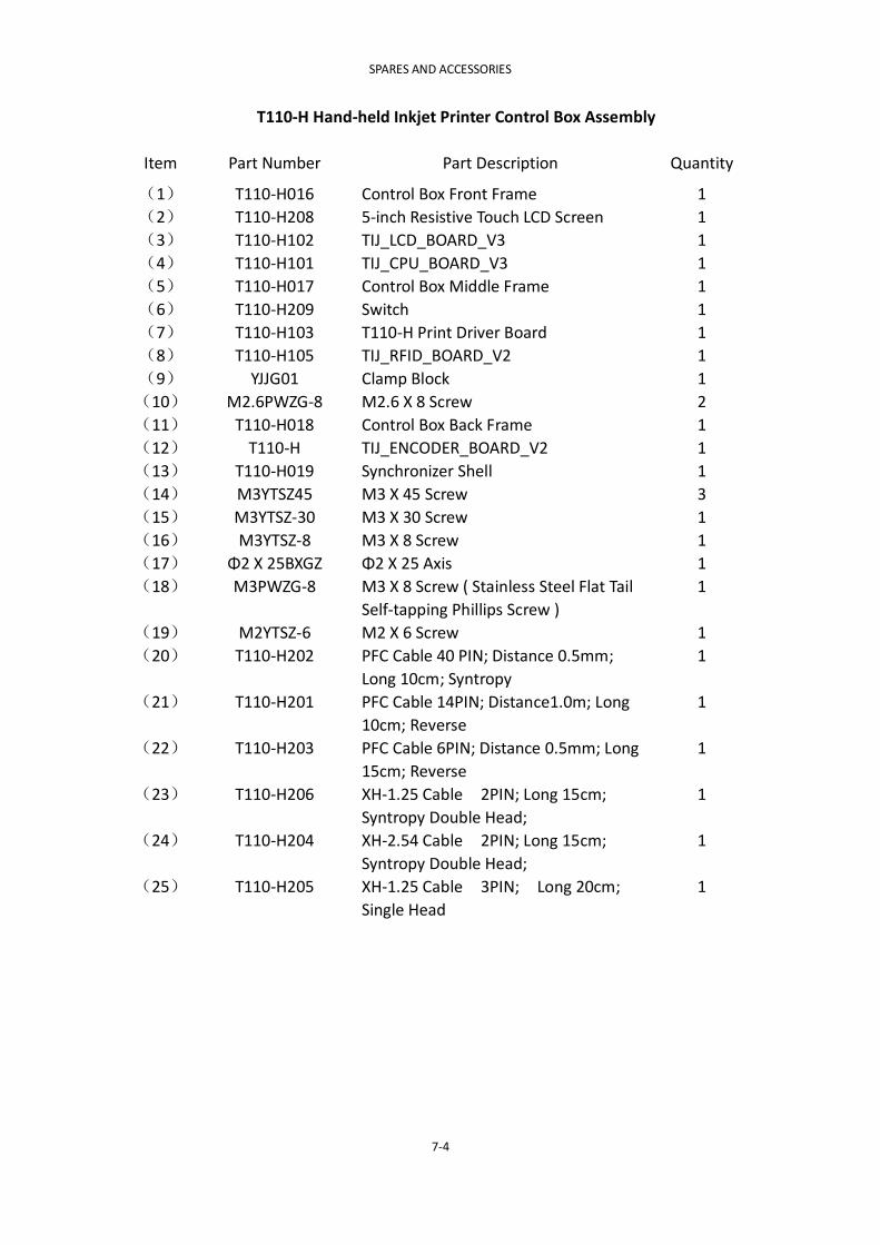
SPARES AND ACCESSORIES
7-4
T110-H Hand-held Inkjet Printer Control Box Assembly
Item Part Number Part Description Quantity
(1) T110-H016 Control Box Front Frame 1
(2) T110-H208 5-inch Resistive Touch LCD Screen 1
(3) T110-H102 TIJ_LCD_BOARD_V3 1
(4) T110-H101 TIJ_CPU_BOARD_V3 1
(5) T110-H017 Control Box Middle Frame 1
(6) T110-H209 Switch 1
(7) T110-H103 T110-H Print Driver Board 1
(8) T110-H105 TIJ_RFID_BOARD_V2 1
(9) YJJG01 Clamp Block 1
(10) M2.6PWZG-8 M2.6 X 8 Screw 2
(11) T110-H018 Control Box Back Frame 1
(12) T110-H TIJ_ENCODER_BOARD_V2 1
(13) T110-H019 Synchronizer Shell 1
(14) M3YTSZ45 M3 X 45 Screw 3
(15) M3YTSZ-30 M3 X 30 Screw 1
(16) M3YTSZ-8 M3 X 8 Screw 1
(17) Φ2 X 25BXGZ Φ2 X 25 Axis 1
(18) M3PWZG-8 M3 X 8 Screw ( Stainless Steel Flat Tail
Self-tapping Phillips Screw )
1
(19) M2YTSZ-6 M2 X 6 Screw 1
(20) T110-H202 PFC Cable 40 PIN; Distance 0.5mm;
Long 10cm; Syntropy
1
(21) T110-H201 PFC Cable 14PIN; Distance1.0m; Long
10cm; Reverse
1
(22) T110-H203 PFC Cable 6PIN; Distance 0.5mm; Long
15cm; Reverse
1
(23) T110-H206 XH-1.25 Cable 2PIN; Long 15cm;
Syntropy Double Head;
1
(24) T110-H204 XH-2.54 Cable 2PIN; Long 15cm;
Syntropy Double Head;
1
(25) T110-H205 XH-1.25 Cable 3PIN; Long 20cm;
Single Head
1

SPARES AND ACCESSORIES
7-5
T110-M
T110 Fo
r Pro
du
ction
Line
Co
ntro
l Box
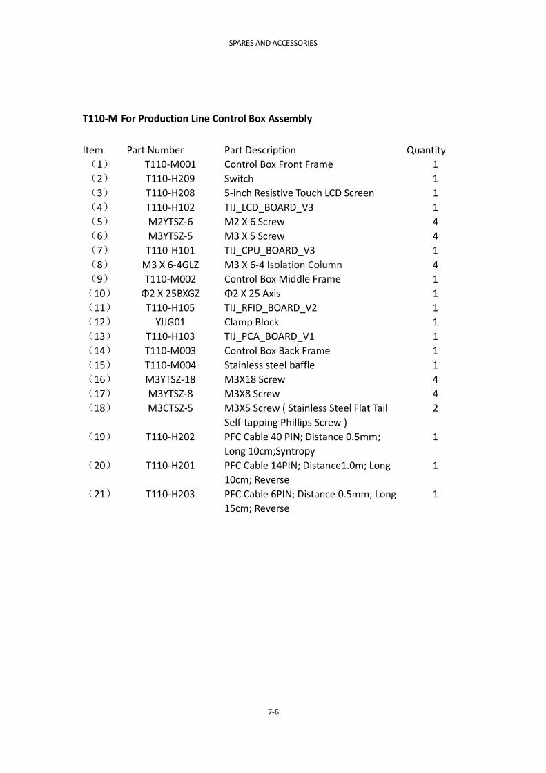
SPARES AND ACCESSORIES
7-6
T110-M For Production Line Control Box Assembly
Item Part Number Part Description Quantity
(1) T110-M001 Control Box Front Frame 1
(2) T110-H209 Switch 1
(3) T110-H208 5-inch Resistive Touch LCD Screen 1
(4) T110-H102 TIJ_LCD_BOARD_V3 1
(5) M2YTSZ-6 M2 X 6 Screw 4
(6) M3YTSZ-5 M3 X 5 Screw 4
(7) T110-H101 TIJ_CPU_BOARD_V3 1
(8) M3 X 6-4GLZ M3 X 6-4 Isolation Column 4
(9) T110-M002 Control Box Middle Frame 1
(10) Φ2 X 25BXGZ Φ2 X 25 Axis 1
(11) T110-H105 TIJ_RFID_BOARD_V2 1
(12) YJJG01 Clamp Block 1
(13) T110-H103 TIJ_PCA_BOARD_V1 1
(14) T110-M003 Control Box Back Frame 1
(15) T110-M004 Stainless steel baffle 1
(16) M3YTSZ-18 M3X18 Screw 4
(17) M3YTSZ-8 M3X8 Screw 4
(18) M3CTSZ-5 M3X5 Screw ( Stainless Steel Flat Tail
Self-tapping Phillips Screw )
2
(19) T110-H202 PFC Cable 40 PIN; Distance 0.5mm;
Long 10cm;Syntropy
1
(20) T110-H201 PFC Cable 14PIN; Distance1.0m; Long
10cm; Reverse
1
(21) T110-H203 PFC Cable 6PIN; Distance 0.5mm; Long
15cm; Reverse
1

SPARES AND ACCESSORIES
7-7
T210 For Production Line Control Box

SPARES AND ACCESSORIES
7-8
T210 For Production Line Control Box Assembly
Item Part Number Part Description Quantity
(1) T210-001 T210 stainless steel Shell 1
(2) T210-002 Switch 1
(3) T210-003 T210 Power Plug 1
(4) T210-004 T210 EVA Wad 1
(5) T210-005 T210-7 inch Touch Screen 1
(6) T210-006 T210 Double-sided Tape 1
(7) M3YTSZ-6 M3X6 Screw 4
(8) T210-007 T210 Screen PCB 1
(9) M3X8-6GLZ M3X8-6 Isolation Column 4
(10) T210-008 T210 MAIN Board 1
(11) M3DP M3 Spring Gasket 4
(12) M3FSLM M3 Relax Nut 4
(13) M3YTSZ-6 M3X6 SCREW 4
(14) T210-009 T210 Baseboard 1
(15) M3X5-6GLZ M3X5-6 Isolation Column 12

SPARES AND ACCESSORIES
7-9
T110-H Handle Assembly
Item Part Number Part Description Quantity
(1) M3CTSZ-4 M3 X 4 Screw 4
(2) T110-H013 Left Handle Case 1
(3) T110-H011 Trigger Button 1
(4) T110-H106 TIJ_CHARGE_BOARD_V2 1
(5) T110-H012 Right Handle Case 1
(6) M3YTSZ-8 M3 X 8 Screw 3
(7) T110-H015 Negative Battery Plate 1
(8) T110-H008 18650 Battery 3
(9) T110-H007 Battery Cover 1
(10) T110-H009 Battery Positive And Negative Bridge 1
(11) T110-H010 Battery Positive Electrode Sheet 1
(12) T110-H014 Battery Negative Bridge 1
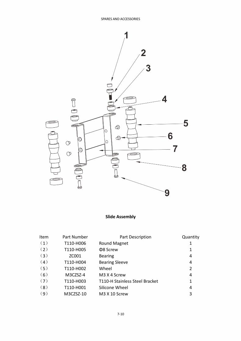
SPARES AND ACCESSORIES
7-10
Slide Assembly
Item Part Number Part Description Quantity
(1) T110-H006 Round Magnet 1
(2) T110-H005 Φ8 Screw 1
(3) ZC001 Bearing 4
(4) T110-H004 Bearing Sleeve 4
(5) T110-H002 Wheel 2
(6) M3CZSZ-4 M3 X 4 Screw 4
(7) T110-H003 T110-H Stainless Steel Bracket 1
(8) T110-H001 Silicone Wheel 4
(9) M3CZSZ-10 M3 X 10 Screw 3

OPTIONS
8-1
PART 8:OPTIONS
T110-M (ONLINE) Production Line Bracket
T110-M (ONLINE) Floor Stand
T210 Production Line Bracket

OPTIONS
8-2
T210 Floor Stand