Embed Size (px)
Citation preview

The INL is a U.S. Department of Energy National Laboratory operated by Battelle Energy Alliance
INL/EXT-09-17011
Systems Analysis Programs for Hands-On Integrated Reliability Evaluations (SAPHIRE) Version 8 Volume 3 Users’ Guide
C. L. Smith K. Vedros K. J. Kvarfordt
March 2011

INL/EXT-09-17011NUREG/CR-7039
Systems Analysis Programs for Hands-On Integrated Reliability Evaluations (SAPHIRE) Version 8
Volume 3 Users’ Guide
C. L. Smith K. Vedros
K. J. Kvarfordt
March 2011
Idaho National Laboratory Idaho Falls, Idaho 83415
http://www.inl.gov
Prepared for the Division of Risk Analysis
Office of Nuclear Regulatory Research U.S. Nuclear Regulatory Commission
Washington, D.C. 20555 Job Code N6423

AVAILABILITY NOTICE
Availability of Reference Materials Cited in NRC Publications
Most documents cited in NRC publications will be available from one of the following sources:
1. The NRC Public Document Room, Rockville Pike, Rockville, MD 20852 ([email protected])
2. The Superintendent of Documents, U. S. Government Printing Office (GPO), Mail Stop SSOP, Washington, DC 20402-9328
3. The National Technical Information Service, Springfield, VA 22161
Although the listing that follows represents the majority of documents cited in NRC publications, it is not intended to be exhaustive.
Referenced documents available for inspection and copying for a fee from the NRC Public Document Room include NRC correspondence and internal NRC memoranda; NRC bulletins, circulars, information notices, inspection and investigative notices; licensee event reports; vendor reports and correspondence; Commission papers; and applicant and licensee documents and correspondence.
The following documents in the NUREG series are available for purchase from the GPO Sales Program: formal NRC staff and contractor reports, NRC-sponsored conference proceedings, international agreement reports, grant publications, and NRC booklets and brochures. Also available are regulatory guides, NRC regulations in the Code of Federal Regulations, andNuclear Regulatory Commission Issuances.
Documents available from the National Technical Information Service include NUREG-series reports and technical reports prepared by other Federal agencies and reports prepared by the Atomic Energy Commission, forerunner agency to the Nuclear Regulatory Commission.
Documents available from public and special technical libraries include all open literature items, such as books, journal articles, and transactions. Federal Register notices, Federal and State legislation, and congressional reports can usually be obtained from these libraries.
Documents such as theses, dissertations, foreign reports and translations, and non-NRC conference proceedings are available for purchase from the organization sponsoring the publication cited.
Single copies of NRC draft reports are available free, to the extent of supply, upon written request to the Office of Administration, Distribution and Mail Services Section U. S. Nuclear Regulatory Commission, Washington, DC 20555-0001.
The public maintains copies of industry codes and standards used in a substantive manner in the NRC regulatory process at the NRC Library, Two White Flint North, 11545 Rockville Pike, Rockville, MD, 20852, for use. Codes and standards are usually copyrighted and may be purchased from the originating organization or, if they are American National Standards, from the American National Standards Institute, 1430 Broadway, New York, NY 10018.

DISCLAIMER NOTICE
This report was prepared as an account of work sponsored by an agency of the United States Government. Neither the United States Government nor any agency thereof, or any of their employees, makes any warranty, expressed or implied, or assumes any legal liability of responsibility for any third party’s use, or the results of such use, or any information, apparatus, product or process disclosed in this report, or represents that its use by such third party would not infringe privately owned rights.

ii
PREVIOUS REPORTS
S. T. Wood, C. L. Smith, K. J. Kvarfordt, S. T. Beck, Systems Analysis Programs for Hands-on Integrated Reliability Evaluations (SAPHIRE) Vol. 1 Summary Manual, NUREG/CR-6952, August 2008.
C. L. Smith, S. T. Wood, W. J. Galyean, J. A. Schroeder, S. T. Beck, M. B. Sattison, Systems Analysis Programs for Hands-on Integrated Reliability Evaluations (SAPHIRE) Vol. 2 Technical Reference, NUREG/CR-6952, August 2008.
K. J. Kvarfordt, S. T. Wood, C. L. Smith, Systems Analysis Programs for Hands-on Integrated Reliability Evaluations (SAPHIRE) Vol. 3 Code Reference, NUREG/CR-6952, August 2008.
S. T. Beck, S. T. Wood, C. L. Smith, Systems Analysis Programs for Hands-on Integrated Reliability Evaluations (SAPHIRE) Vol. 4 Tutorial, NUREG/CR-6952, August 2008.
C. L. Smith, J. Schroeder, S. T. Beck, Systems Analysis Programs for Hands-on Integrated Reliability Evaluations (SAPHIRE) Vol. 5 GEM Manual, NUREG/CR-6952, August 2008.
C. L. Smith, R. Nims, K. J. Kvarfordt, C. Wharton, Systems Analysis Programs for Hands-on Integrated Reliability Evaluations (SAPHIRE) Vol. 6 Quality Assurance Manual, NUREG/CR-6952, August 2008.
K. J. Kvarfordt, S. T. Wood, C. L. Smith, Systems Analysis Programs for Hands-on Integrated Reliability Evaluations (SAPHIRE) Vol. 7 Data Loading, NUREG/CR-6952, August 2008.
Smith, C. L., et al., Testing, Verifying, and Validating SAPHIRE Versions 6.0 and 7.0,NUREG/CR-6688, October 2000.
K. D. Russell, et al. Systems Analysis Programs for Hands-on Reliability Evaluations (SAPHIRE) Version 6.0 - System Overview Manual, NUREG/CR-6532, May 1999.
K. D. Russell et al., Integrated Reliability and Risk Analysis System (IRRAS) Version 5.0, Volume 2 - Reference Manual, NUREG/CR-6116, EGG-2716, July 1994.
K. D. Russell et al., Verification and Validation (V&V), Volume 9 – Reference Manual,NUREG/CR-6116, EGG-2716, July 1994.
K. D. Russell et al., Integrated Reliability and Risk Analysis System (IRRAS) Version 4.0, Volume 1 - Reference Manual, NUREG/CR-5813, EGG-2664, January 1992.
K. D. Russell et al., Integrated Reliability and Risk Analysis System (IRRAS) Version 2.5 Reference Manual, NUREG/CR-5300, EGG-2613, March 1991.
K. D. Russell, M. B. Sattison, D. M. Rasmuson, Integrated Reliability and Risk Analysis System (IRRAS) - Version 2.0 User's Guide, NUREG/CR-5111, EGG-2535, manuscript completed March 1989, published June 1990.
K. D. Russell, D. M. Snider, M. B. Sattison, H. D. Stewart, S.D. Matthews, K. L. Wagner, Integrated Reliability and Risk Analysis System (IRRAS) User's Guide - Version 1.0 (DRAFT),NUREG/CR-4844, EGG-2495, June 1987.

iii
ABSTRACT
The Systems Analysis Programs for Hands-on Integrated Reliability Evaluations (SAPHIRE) is a software application developed for performing a complete probabilistic risk assessment (PRA) using a personal computer. SAPHIRE is funded by the U.S. Nuclear Regulatory Commission (NRC) and developed by the Idaho National Laboratory (INL). The INL's primary role in this project is that of software developer. However, the INL also plays an important role in technology transfer by interfacing and supporting SAPHIRE users comprised of a wide range of PRA practitioners from the NRC, national laboratories, the private sector, and foreign countries.
SAPHIRE can be used to model a complex system’s response to initiating events, quantify associated damage outcome frequencies, and identify important contributors to this damage (Level 1 PRA) and to analyze containment performance during a severe accident and quantify radioactive releases (Level 2 PRA). It can be used for a PRA evaluating a variety of operating conditions, for example, for a nuclear reactor at full power, low power, or at shutdown conditions. Furthermore, SAPHIRE can be used to analyze both internal and external initiating events and has special features for transforming models built for internal event analysis to models for external event analysis. It can also be used in a limited manner to quantify risk in terms of release consequences to both the public and the environment (Level 3 PRA).
This reference guide will introduce the SAPHIRE Version 8.0 software. A brief discussion of the purpose and history of the software is included along with general information such as installation instructions, starting and stopping the program, and some pointers on how to get around inside the program. Next, database concepts and structure are discussed. Following that discussion are 14 additional sections covering key elements of the SAPHIRE software.

iv
v
FOREWORD
The U.S. Nuclear Regulatory Commission (NRC) has developed the Systems Analysis Programs for Hands-on Integrated Reliability Evaluations (SAPHIRE) software that is used to perform probabilistic risk assessments (PRAs) on a personal computer. SAPHIRE enables users to supply basic event data, create and solve fault and event trees, perform uncertainty analyses, and generate reports. In that way, analysts can perform PRAs for any complex system, facility, or process.
For nuclear power plant PRAs, SAPHIRE can be used to model a plant's response to initiating events, quantify core damage frequencies, and identify important contributors to core damage (Level 1 PRA). The program also can be used to evaluate containment failure and release models for severe accident conditions given that core damage has occurred (Level 2 PRA). In so doing, the analyst could build the PRA model assuming that the reactor is initially at full power, low power, or shutdown. In addition, SAPHIRE can be used to analyze both internal and external events and, in a limited manner, to quantify the frequency of release consequences (Level 3 PRA). Because this software is a very detailed technical tool, users should be familiar with PRA concepts and methods used to perform such analyses.
SAPHIRE has evolved with advances in computer technology and users’ needs. Starting with Version 5, SAPHIRE operated in the Microsoft Windows™ environment. Versions 6 and 7 included features and capabilities for developing and using larger, more complex models. SAPHIRE Version 8 includes significant new features and capabilities to meet user needs for NRC risk-informed programs. In general, these include:
Improved user interfaces supporting NRC’s Significance Determination Process, event and condition assessments, and more detailed types of PRA analyses.
Development and use of NRC’s Standardized Plant Analysis Risk models.
New and improved solving algorithms.
Support features for user-friendliness.
This NUREG-series report comprises seven volumes as outlined below and incorporates new features and capabilities of Version 8.
Volume 1, “Overview and Summary”
Volume 1 provides an overview of the functions and features available in SAPHIRE Version 8 and presents general instructions for using the software.
Volume 2, “Technical Reference”
Volume 2 summarizes the fundamental mathematical concepts of sets and logic, fault trees, and probability. It then describes the algorithms used to construct a fault tree and to obtain the minimal cut sets. This report presents the formulas used to obtain the probability of the top event from the minimal cut sets and the formulas for probabilities that apply for various assumptions concerning reparability and mission time. In addition, it defines the measures of basic event importance that SAPHIRE can calculate. This volume also gives an overview of uncertainty analysis using simple Monte Carlo sampling or Latin Hypercube sampling and states

vi
the algorithms used by this program to generate random basic event probabilities from various distributions. Finally, this report discusses enhanced and new capabilities such as post-processing rules, integrated model solving using model types, and workspace analysis routines.
Volume 3, “Users’ Guide”
Volume 3 provides a brief discussion of the purpose and history of the software as well as general information such as installation instructions, starting and stopping the program, and some pointers on how to get around inside the program. Next, it discusses database concepts and structure. The following nine sections (one for each of the menu options on the SAPHIRE main menu) furnish the purpose and general capabilities for each option. Finally, Volume 3 provides the capabilities and limitations of the software.
Volume 4, “Tutorial”
Volume 4 provides a series of lessons that guide the user through basic steps common to most analyses performed with SAPHIRE.
Volume 5, “Workspaces”
Volume 5 describes the functionality and process behind SAPHIRE Version 8 workspaces. Workspaces provide an area in which a PRA model can be analyzed to obtain risk insights for a given initiating event or condition. Workspaces replace the “Graphical Evaluation Module” in earlier SAPHIRE versions.
Volume 6, “Quality Assurance”
Volume 6 is designed to describe how the SAPHIRE software quality assurance (QA) is performed for Version 8, what constitutes its parts, and the limitations of those processes. In addition, this report describes the Independent Verification and Validation that was conducted for Version 8 as part of an overall QA process.
Volume 7, “Data Loading”
Volume 7 is designed to guide the user through the basic procedures necessary to enter PRA data into the SAPHIRE program using SAPHIRE’s MAR-D ASCII-text (or “flat file”) data formats. In addition, this manual covers loading data through the new Accident Sequence Matrix and discusses the Project Integrate interfaces with SAPHIRE.
________________________________
Christiana H. Lui, Director
Division of Risk Analysis
Office of Nuclear Regulatory Research
U.S. Nuclear Regulatory Commission

vii
CONTENTS
Section Page
PREVIOUS REPORTS ................................................................................................................. ii�
ABSTRACT .................................................................................................................................. iii�
FOREWORD ................................................................................................................................. v�
LIST OF FIGURES .................................................................................................................... xiv�
LIST OF TABLES ....................................................................................................................... xiv�
EXECUTIVE SUMMARY ............................................................................................................ xv�
ACKNOWLEDGEMENTS .......................................................................................................... xvii�
ACRONYMS .............................................................................................................................. xix�
1.� INTRODUCTION........................................................................................................ 1�
1.1� Background ................................................................................................................ 1�
1.2� Overview of SAPHIRE Users’ Guide .......................................................................... 2�
1.3� SAPHIRE - What Is It and What Can It Do? .............................................................. 3�
1.4� Installation of SAPHIRE ............................................................................................. 4�
1.5� Un-installation of SAPHIRE ........................................................................................ 5�
1.6� Starting SAPHIRE ...................................................................................................... 5�
1.7� Stopping SAPHIRE .................................................................................................... 5�
1.8� Help from within SAPHIRE ......................................................................................... 6�
1.9� SAPHIRE Project Settings ......................................................................................... 6�
1.10� SAPHIRE User Settings ............................................................................................. 7�
1.10.1� General Display User Settings ....................................................................... 8�1.10.2� Analysis Options Settings ............................................................................... 9�1.10.3� Rules Editor Settings .................................................................................... 10�1.10.4� Graphical Editor Constants Settings ............................................................ 11�1.10.5� Significance Determination Process Settings ............................................... 11�1.10.6� "RASP CCF" Constants ............................................................................... 12�
1.11� User Support ............................................................................................................ 13�
2.� SAPHIRE PROJECTS ............................................................................................. 15�
2.1� Opening a Project .................................................................................................... 15�
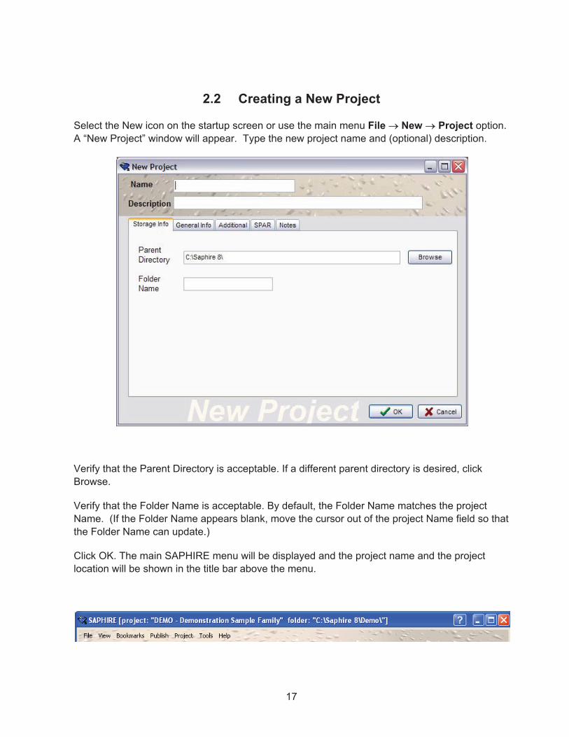
2.2� Creating a New Project ............................................................................................ 17�
2.3� Project Folder Structure ........................................................................................... 18�
3.� MODEL EDITING ..................................................................................................... 19�

viii
3.1� SAPHIRE Model Development Area ........................................................................ 19�
3.1.1� SAPHIRE Window Management .................................................................. 19�3.1.2� Sizing a Window ........................................................................................... 19�3.1.3� Open Windows ............................................................................................. 19�
3.2� Lists Panel ................................................................................................................ 20�
3.2.1� List Filters ..................................................................................................... 20�3.2.2� Selecting from a List ..................................................................................... 20�
4.� BASIC EVENT EDITING .......................................................................................... 23�
4.1� Basic Event Terminology ......................................................................................... 23�
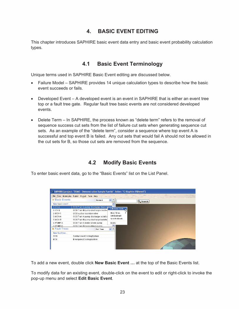
4.2� Modify Basic Events ................................................................................................. 23�
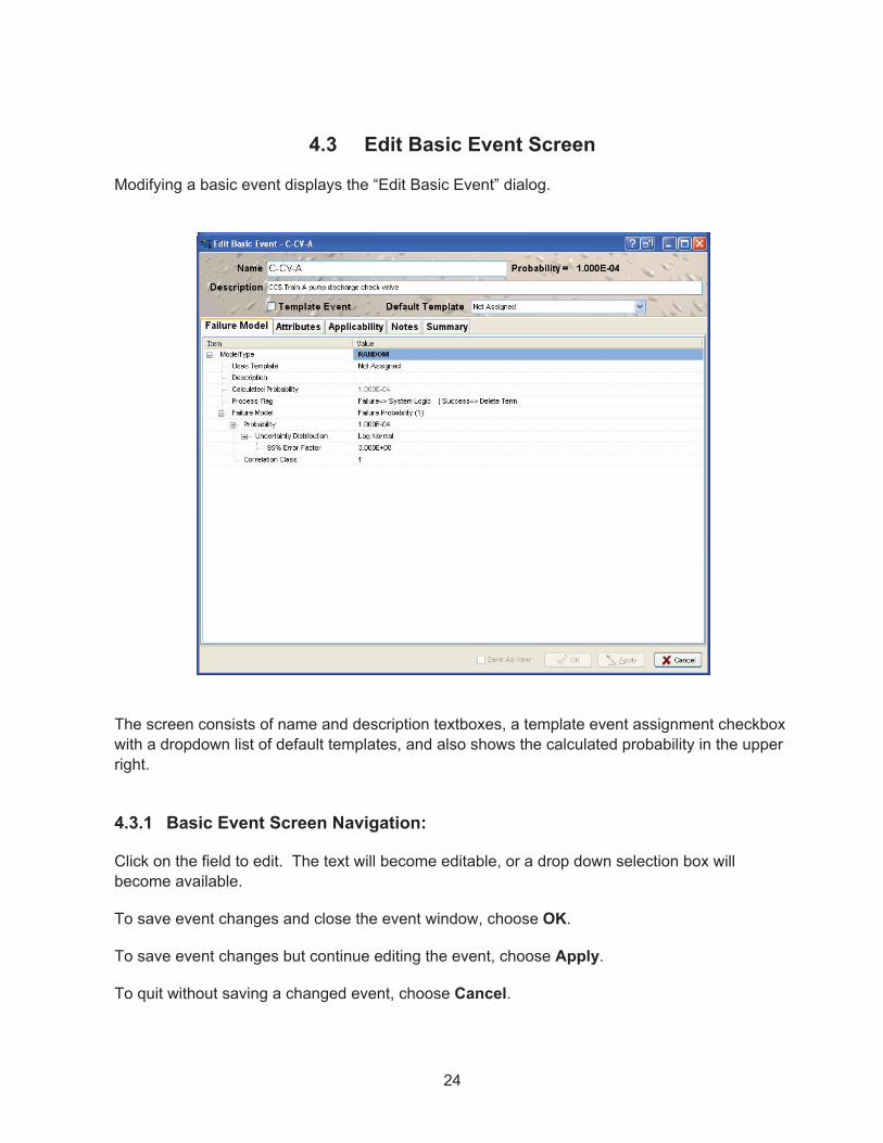
4.3� Edit Basic Event Screen ........................................................................................... 24�
4.3.1� Basic Event Screen Navigation: ................................................................... 24�4.3.2� Basic Event Name and Description .............................................................. 25�
4.4� Basic Event Failure Model ....................................................................................... 25�
4.4.1� Event Default Template ................................................................................ 25�4.4.2� Model Type ................................................................................................... 25�4.4.3� Description ................................................................................................... 25�4.4.4� Calculated Probability ................................................................................... 25�4.4.5� Process Flags ............................................................................................... 25�4.4.6� Uses Template ............................................................................................. 27�4.4.7� Failure Model ................................................................................................ 27�4.4.8� Failure Model Parameters ............................................................................ 27�4.4.9� Uncertainty Distribution ................................................................................ 31�4.4.10� Correlation Class .......................................................................................... 31�
4.5� Basic Event Attributes .............................................................................................. 31�
4.5.1� Template Event ............................................................................................ 32�4.5.2� Event Types: ................................................................................................ 32�4.5.3� Event Display Types: .................................................................................... 32�4.5.4� Event Categories .......................................................................................... 33�
4.6� Basic Event Applicability .......................................................................................... 33�
4.7� Basic Event Notes .................................................................................................... 34�
4.8� Basic Event Summary .............................................................................................. 35�
4.9� Template Events ...................................................................................................... 36�
4.10� Compound Events .................................................................................................... 39�
4.11� Common-Cause Failure Compound Events ............................................................ 40�
4.11.1� Multiple Greek Letter (MGL) method (old approach) .................................... 41�4.11.2� Alpha Factor method (old approach) ............................................................ 41�4.11.3� RASP Common-Cause Failure Module ........................................................ 43�
ix
4.12� Human Error Event .................................................................................................. 50�
4.13� Base Units used for Event Data ............................................................................... 53�
5.� BUILDING FAULT TREES ....................................................................................... 55�
5.1� Fault Tree Development ........................................................................................... 55�
5.2� SAPHIRE Fault Tree Terminology ........................................................................... 56�
5.3� SAPHIRE Fault Tree Conventions ........................................................................... 56�
5.4� Opening a New Fault Tree ....................................................................................... 57�
5.5� Basic Event Symbols ............................................................................................... 58�
5.5.1� Fault Tree Graphic and Logic Symbols for Basic Events ............................. 58�
5.6� Logic Gate Symbols ................................................................................................. 60�
5.6.1� Fault Tree Graphic Symbols for Gates ......................................................... 60�
5.7� Fault Tree Main Menu .............................................................................................. 63�
5.7.1� File ................................................................................................................ 63�5.7.2� Edit ............................................................................................................... 63�5.7.3� Insert ............................................................................................................ 64�5.7.4� View.............................................................................................................. 64�
5.8� Zooming ................................................................................................................... 65�
5.9� Ending the Fault Tree Editing Session ..................................................................... 65�
5.10� Example Fault Tree .................................................................................................. 66�
6.� BUILDING EVENT TREES ...................................................................................... 67�
6.1� Event Tree Development ......................................................................................... 67�
6.2� Event Tree Terminology ........................................................................................... 68�
6.3� SAPHIRE Event Tree Conventions .......................................................................... 68�
6.4� Beginning an Event Tree Editing Session ................................................................ 69�
6.4.1� Adding a New Event Tree: ........................................................................... 69�6.4.2� Opening an Existing Event Tree: .................................................................. 70�
6.5� Inserting Top Events ................................................................................................ 70�
6.6� Modifying top events ................................................................................................ 71�
6.6.1� Deleting a top event ..................................................................................... 71�
6.7� Editing Event Tree Branches ................................................................................... 72�
6.7.1� Adding event tree branches ......................................................................... 72�6.7.2� Deleting branches ........................................................................................ 72�6.7.3� Adding text to a branch ................................................................................ 72�6.7.4� Expanding and Collapsing branches ............................................................ 73�
6.8� Editing Sequence/End State Information ................................................................. 73�

x
6.8.1� Edit End-State Description ........................................................................... 73�6.8.2� View Sequence/End State Information ......................................................... 74�6.8.3� Modifying an End State to be a Transfer ...................................................... 75�6.8.4� Disabling an End State ................................................................................. 75�
6.9� Editing the Visual Display of Event Trees ................................................................ 76�
6.9.1� Adjust the visual display of the event tree .................................................... 76�6.9.2� Zooming ....................................................................................................... 76�
6.10� Ending the event tree editing session ...................................................................... 76�
7.� SOLVING FAULT TREES ........................................................................................ 79�
7.1� GENERATING FAULT TREE CUT SETS ................................................................ 79�
7.1.1� Prerequisites for Generating Fault Tree Cut Sets ........................................ 79�7.1.2� Menus and options for fault tree cut set generation ..................................... 80�7.1.3� Truncation Parameters ................................................................................. 81�7.1.4� Solution Steps .............................................................................................. 81�7.1.5� Solve Quantification Methods ....................................................................... 82�7.1.6� Displaying Fault Tree Cut Set Results ......................................................... 83�7.1.7� Selecting Fault Tree Cut Sets to View .......................................................... 83�
7.2� Analyzing Fault Tree "Sub-trees" ............................................................................. 85�
7.3� FAULT TREE UNCERTAINTY ANALYSIS .............................................................. 87�
7.3.1� Monte Carlo Sampling .................................................................................. 87�7.3.2� Latin Hypercube Sampling ........................................................................... 87�7.3.3� Uncertainty Distributions for Basic Events ................................................... 87�7.3.4� Menus and Options for Performing Fault Tree Uncertainty Analysis ........... 88�
7.4� FAULT TREE IMPORTANCE ANALYSIS ................................................................ 90�
7.4.1� Fault Tree Importance Measures ................................................................. 90�7.4.2� Definitions of the Importance Measures ....................................................... 90�7.4.3� Importance Menus and Options ................................................................... 91�
8.� SOLVING EVENT TREES ....................................................................................... 95�
8.1� Linking Event Tree Sequences ................................................................................ 95�
8.1.1� Linking Event Trees ...................................................................................... 95�
8.2� Generating Event Tree Cut Sets .............................................................................. 95�
8.2.1� Prerequisites for Generating Event Tree Cut Sets ....................................... 95�8.2.2� Menus and Options for Event Tree Cut Set Generation ............................... 96�8.2.3� Cut Set Generation Cutoff Values ................................................................ 97�8.2.4� Solution Steps .............................................................................................. 98�8.2.5� Displaying Event Tree Cut Set Results ........................................................ 98�
8.3� Additional Event Tree Sequence Cut Sets Analysis Features ............................... 100�
8.4� Sequence Uncertainty Analysis ............................................................................. 100�

xi
8.4.1� Menus and Options for Performing Sequence Uncertainty Analysis .......... 101�8.4.2� Uncertainty Calculation Values .................................................................. 102�8.4.3� Uncertainty Results .................................................................................... 102�
8.5� Viewing Sequence Importance Measures .............................................................. 104�
9.� VIEWING CUT SETS ............................................................................................. 107�
9.1� The View Cut Sets Option ...................................................................................... 107�
9.2� The Event Slice Option .......................................................................................... 108�
9.3� The Cutoff Slice Option .......................................................................................... 111�
10.� USING DATABASE FILES ..................................................................................... 113�
10.1� Archive Project Utility ............................................................................................. 113�
10.2� Integrate Project Utility ........................................................................................... 114�
10.3� The MAR-D Module ............................................................................................... 116�
10.3.1� MAR-D File Format .................................................................................... 117�10.3.2� MAR-D Load and Extract Menus ................................................................ 122�
11.� MODEL TYPES ...................................................................................................... 125�
11.1� Describing Model Types ......................................................................................... 125�
11.2� Using Model Types ................................................................................................ 126�
12.� FLAG SETS ........................................................................................................... 129�
12.1� Making a Flag Set .................................................................................................. 130�
12.2� Using a Flag Set ..................................................................................................... 131�
13.� THE SAPHIRE RULES EDITORS ......................................................................... 133�
13.1� LINKING EVENT TREES ....................................................................................... 136�
13.1.1� Menus and Options for Linking Event Tree Sequences ............................. 136�13.1.2� Link Event Trees Rules Nomenclature and Structure ................................ 137�13.1.3� Linking Rule Structure (Example 1 – If -Then) ........................................... 138�13.1.4� Linking Rule Structure (Example 2 – if-then-elsif) ...................................... 139�13.1.5� Linking Rule Structure (Example 3 – if-then-elsif-else) .............................. 139�13.1.6� Linking Rule Structure (Example 4 – always) ............................................. 140�13.1.7� Linking Rule Structure (Example 5 – If –Then with wildcards) ................... 140�
13.2� Linking Rules "Macro" Structures ........................................................................... 141�
13.2.1� Linking Rule Structure (Example 6 – macros) ............................................ 141�13.2.2� Linking Rule Structure (Example 7 – not found ~) ...................................... 142�13.2.3� Linking Rule Structure (Example 8 – ignoring sequences via the SKIP
keyword) ..................................................................................................... 142�
13.3� Changing Transfers Trees using Link Rules .......................................................... 143�

xii
13.3.1� Linking Rule Structure (Example 9 – changing the transfer tree via EVENTREE) ............................................................................................... 143�
13.4� Event Tree Linking Rule Keywords and Nomenclature .......................................... 144�
13.5� Rules for Binary and Multiple-Split Branches ......................................................... 147�
14.� POST-PROCESSING RULES ............................................................................... 151�
14.1� Post-Processing Rules Editor Introduction ............................................................. 151�
14.2� Post-processing Rules Nomenclature and Structure ............................................. 152�
14.2.1� Post-processing Rule Structure (Example 1 – if-then) ............................... 153�14.2.2� Post-processing Rule Structure (Example 2 – if-then-elsif) ........................ 153�14.2.3� Post-processing Rule Structure (Example 3 – appending recovery actions) ........................................................................................ 154�14.2.4� Post-processing Rule Structure (Example 4 – mutually exclusive event
removal) ..................................................................................................... 154�14.2.5� Post-processing Rule Structure (Example 5 – including common-cause
failure events) ............................................................................................. 155�14.2.6� Post-processing Rule Structure (Example 6 – use of top events) .............. 156�
14.3� Post-processing Rule Keywords and Nomenclature .............................................. 156�
14.4� Fault Tree Post-processing Rules .......................................................................... 159�
14.5� Event Tree Sequence Post-processing Rules ....................................................... 160�
15.� END STATE ANALYSIS ........................................................................................ 161�
15.1� End State Analysis Approaches ............................................................................. 161�
15.2� End States by Specifying Sequence End States ................................................... 161�
15.3� Gather End State Cut Sets ..................................................................................... 162�
15.3.1� Options to Gather End States Cut Sets ...................................................... 162�15.3.2� Gather Cut Sets .......................................................................................... 163�15.3.3� Update / Quantify Cut Sets ......................................................................... 163�15.3.4� Clear Cut Set Partitions .............................................................................. 163�15.3.5� Apply Partition Rules .................................................................................. 163�15.3.6� Copy Cut Sets to Base Case ...................................................................... 163�15.3.7� Cut Set Truncation ..................................................................................... 163�15.3.8� Gather By ................................................................................................... 163�15.3.9� Solve For Model Types .............................................................................. 164�
15.4� Description of End States list menu options ........................................................... 164�
15.4.1� Gather ........................................................................................................ 164�15.4.2� View Summary Results .............................................................................. 164�15.4.3� View Importance Measures ........................................................................ 165�15.4.4� View Uncertainty ........................................................................................ 165�15.4.5� View Cut Sets ............................................................................................. 165�
15.5� End States via Partition Rules ................................................................................ 166�

xiii
15.6� End State Partitioning Rules Nomenclature and Structure .................................... 166�
15.6.1� Partition Rule Structure (Example 1 – if-then) ............................................ 167�15.6.2� Partition Rule Structure (Example 2 – if-always) ........................................ 167�15.6.3� Partition Rule Structure (Example 3 – if-then-elsif) .................................... 168�15.6.4� Partition Rule Structure (Example 4 – if-then-elsif-else) ............................ 169�15.6.5� Partition Rule Structure (Example 5 – Macros) .......................................... 169�15.6.6� Partition Rule Structure (Example 6 – Macros and ~) ................................ 170�15.6.7� Partition Rule Structure (Example 7 – Current Partition) ............................ 170�15.6.8� Partition Rule Structure (Example 8 – Global Partition) ............................. 171�15.6.9� Partition Rule Structure (Example 9 – Global Partition and Transfer) ........ 172�
15.7� Partition Rule Keywords and Nomenclature .......................................................... 173�
15.8� Partition Rule Example ........................................................................................... 176�
15.8.1� Creating the Partition Rule ......................................................................... 176�15.8.2� Applying the Partitioning Rules .................................................................. 178�15.8.3� Using End State Analysis to Gather the Partitioned Cut Sets .................... 178�15.8.4� Reporting End State Results ...................................................................... 180�
15.9� Resetting or Deleting Partition Rule End States .................................................... 181�

xiv
LIST OF FIGURES
Figure Page
Figure 1. Main SAPHIRE 8 window upon startup ........................................................................ 3�
Figure 2. Edit project options screen ........................................................................................... 6�
Figure 3. Setting up a basic event to be a template event ......................................................... 36�
Figure 4. Using a template event ............................................................................................... 38�
Figure 5. Example graphical event tree ..................................................................................... 69�
Figure 6. Uncertainty analysis dialog ......................................................................................... 89�
Figure 7. Illustration of the uncertainty in importance measures ............................................. 105�
Figure 8. First step of the Project Integration option ................................................................ 114�
Figure 9. MAR-D folder output structure and location .............................................................. 118�
Figure 10. Editing a model type ............................................................................................... 126�
Figure 11. Solve cut sets screen to indicate model type .......................................................... 128�
Figure 12. Solving end state cut sets dialog ............................................................................ 162�
LIST OF TABLES
Table Page
Table 1. Sequence Top Process Flags. ..................................................................................... 26�
Table 2. Fault Tree Process Flags. ............................................................................................ 27�
Table 3. SAPHIRE failure model (i.e., calculation type) data entry requirements. ..................... 28�
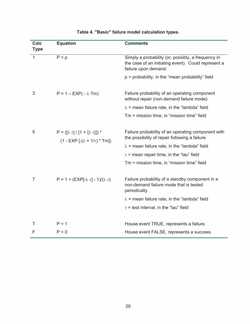
Table 4. "Basic" failure model calculation types. ........................................................................ 29�
Table 5. “Advanced” failure model calculation types. ................................................................ 30�

xv
EXECUTIVE SUMMARY
The U.S. Nuclear Regulatory Commission (NRC) has developed a powerful personal computer (PC) software application for performing probabilistic risk assessments (PRAs), called Systems Analysis Programs for Hands-on Integrated Reliability Evaluations (SAPHIRE). Using SAPHIRE 8 on a PC, an analyst can perform a PRA for any complex system, facility, or process. SAPHIRE development and maintenance has been undertaken by the Idaho National Laboratory (INL). The INL began development of a PRA software application on a PC in the mid 1980s when the potential of PC applications started being recognized. The initial version, Integrated Risk and Reliability Analysis System (IRRAS), was released by the Idaho National Engineering Laboratory (now Idaho National Laboratory) in February 1987. The development of IRRAS continued over the following years, leading SAPHIRE to become a powerful PRA tool.
SAPHIRE 8, building upon these earlier versions, provides the functions required for performing a PRA. Users can supply basic event data, create and solve fault trees and event trees, perform uncertainty analyses, and generate reports. Extending this analysis, Workspaces are user-friendly interface that streamlines and automates select SAPHIRE analysis processes.
SAPHIRE contains improved editors or options for creating event trees and fault trees, defining accident sequences and basic event failure data, solving system fault trees and accident sequence event trees, quantifying cut sets, performing sensitivity and uncertainty analyses, documenting the results, and generating reports. SAPHIRE capabilities for performing a PRA are summarized below.
� Graphical fault tree construction � Graphical event tree construction � Rule-based fault tree linking � Fast cut set generation � Fault tree flag sets � Failure data � Uncertainty analysis � Cut set editor, slice, display, and recovery analysis tools � Cut set path tracing � Cut set comparison � Cut set post-processing rules � Cut set end state partitioning � End state analysis � User-defined model types � User-defined basic event attributes
The document describes how to use the various SAPHIRE modules to exercise the capabilities listed above.

xvi

xvii
ACKNOWLEDGEMENTS
We would like to specifically acknowledge Mr. Dan O’Neal of the U.S. Nuclear Regulatory Commission for his contribution to the development this report.

xviii

xix
ACRONYMS
CDF cumulative distribution function
DOD Department of Defense
DOE Department of Energy
EF error factor
FEP Fault Tree, Event Tree, and Piping and Instrumentation Diagram
GEM Graphical Evaluation Module
HEP human error probability
HRA human reliability analysis
INEEL Idaho National Engineering and Environmental Laboratory
INL Idaho National Laboratory
IRRAS Integrated Reliability and Risk Analysis System
LHS Latin Hypercube Sampling
MAR-D Models and Results Database
NRC Nuclear Regulatory Commission
PC personal computer
PRA probabilistic risk analysis
PSF performance shaping factor
RAW risk achievement worth
SAPHIRE Systems Analysis Programs for Hands-on Integrated Reliability Evaluations
SARA System Analysis and Risk Assessment
SPAR Standardized Plant Analysis Risk


1
Systems Analysis Programs for Hands-on Integrated Reliability Evaluations (SAPHIRE) Version 8
Volume 3 Users’ Guide 1. INTRODUCTION
1.1 Background
The U.S. Nuclear Regulatory Commission (NRC) has developed a powerful personal computer (PC) software application for performing probabilistic risk assessments (PRAs), called Systems Analysis Programs for Hands-on Integrated Reliability Evaluations (SAPHIRE) Version 8.
Using SAPHIRE 8 on a PC, an analyst can perform a PRA for any complex system, facility, or process. Regarding nuclear power plants, SAPHIRE can be used to model a plant’s response to initiating events, quantify associated core damage frequencies, and identify important contributors to core damage (Level 1 PRA). It can also be used to evaluate containment failure and release models for severe accident conditions, given that core damage has occurred (Level 2 PRA). It can be used for a PRA assuming that the reactor is at full power, at low power, or at shutdown conditions. Furthermore, it can be used to analyze both internal and external initiating events, and it has special features for transforming models built for internal event analysis to models for external event analysis. It can also be used in a limited manner to quantify risk for release consequences to both the public and the environment (Level 3 PRA). For all of these models, SAPHIRE can evaluate the uncertainty inherent in the probabilistic models.
SAPHIRE development and maintenance has been undertaken by the Idaho National Laboratory (INL). The INL began development of a PRA software application on a PC in the mid 1980s when the enormous potential of PC applications started being recognized. The initial version, Integrated Risk and Reliability Analysis System (IRRAS), was released by the Idaho National Engineering Laboratory (now Idaho National Laboratory) in February 1987. IRRAS was an immediate success, because it clearly demonstrated the feasibility of performing reliability and risk assessments on a PC and because of its tremendous need (Russell 1987). Development of IRRAS continued over the following years. However, limitations to the state of the-art during those initial stages led to the development of several independent modules to complement IRRAS capabilities (Russell 1990; 1991; 1992; 1994). These modules were known as Models and Results Database (MAR-D), System Analysis and Risk Assessment (SARA), and Fault Tree, Event Tree, and Piping and Instrumentation Diagram (FEP).
IRRAS was developed primarily for performing a Level 1 PRA. It contained functions for creating event trees and fault trees, defining accident sequences and basic event failure data, solving system fault trees and accident sequence event trees, quantifying cut sets, performing sensitivity and uncertainty analyses, documenting the results, and generating reports.
MAR-D provided the means for loading and unloading PRA data from the IRRAS relational database. MAR-D used a simple ASCII data format. This format allowed interchange of data

2
between PRAs performed with different types of software; data of PRAs performed by different codes could be converted into the data format appropriate for IRRAS, and vice-versa.
SARA provided the capability to access PRA data and results (descriptive facility information, failure data, event trees, fault trees, plant system model diagrams, and dominant accident sequences) stored in MAR-D. With SARA, a user could review and compare results of existing PRAs. It also provided the capability for performing limited sensitivity analyses. SARA was intended to provide easier access to PRA results to users that did not have the level of sophistication required to use IRRAS.
FEP provided common access to the suite of graphical editors. The fault tree and event tree editors were accessible through FEP as well as through IRRAS, whereas the piping and instrumentation diagram (P&ID) editor was only accessible through FEP. With these editors an analyst could construct from scratch as well as modify fault tree, event tree, and plant drawing graphical figures needed in a PRA.
Previous versions of SAPHIRE consisted of the suite of these modules. Taking advantage of the Windows 95 (or Windows NT) environment, all of these modules were integrated into SAPHIRE Version 6; more features were added; and the user interface was simplified. In this document, the acronym “SAPHIRE” refers to SAPHIRE Version 8 unless otherwise indicated.
1.2 Overview of SAPHIRE Users’ Guide
The SAPHIRE Users’ Guide material is intended to be a stand-alone reference document. After starting SAPHIRE, the main screen displays will be shown as they appear on the video display (Figure 1). To continue, click the “green arrow” to either modify the Current Project or to Perform an Analysis with the Current Project.

3
Figure 1. Main SAPHIRE 8 window upon startup
The left side of the screen displays a resizable, customizable series of lists containing important PRA elements found in the current project. This series of lists is referred to as the List Panel and can be added to or subtracted from by using View on the main menu.
1.3 SAPHIRE - What Is It and What Can It Do?
SAPHIRE is an integrated PRA software tool that gives a user the ability to create and analyze fault trees and event trees using a personal computer. IRRAS was originally released in 1987
When discussing a particular sequence of menu options, the nomenclature
MAIN Menu � Submenu Option
will be used to indicate the main SAPHIRE menu option and any successive submenu options.

4
(version 1.0). Other versions of IRRAS include 2.0, 2.5, and 4.0. Additions and improvements have been added to each version. Creation of 32-bit IRRAS, version 5.0, in 1992 resulted in an order of magnitude decrease in analysis time. New features included: individual codes modules combined into a single module; end state analysis; fire, flood, and seismic modules; rule-based cut set processing; and rule-based fault tree to event tree linking. SAPHIRE for Windows, version 6.0, was released in 1997. Use of a Windows user interface makes SAPHIRE easier to learn and use. SAPHIRE for Windows, version 7.0, was released in 1999. This is the latest production version of the SAPHIRE code.
SAPHIRE for Windows, version 8.0, is the current development version, and contains:
� PC-based fault tree and event tree graphical and text editors � Cut set generation and quantification � Importance measures and uncertainty modules � Relational database with cross-referencing features � External events analysis (e.g., seismic, location transformation) � Rule-based recovery and end-state analysis � Common Cause Failure (CCF) basic event capabilities
The SAPHIRE minimal hardware requirements are:
� Windows XP or greater � Pentium class IBM-PC compatible with 2-button mouse � 50 MB free disk space (minimum for installation)
1.4 Installation of SAPHIRE
Perform the following steps to install SAPHIRE:
� Place the installation CD into the CD drive. Alternatively, place the downloaded installation executable on the hard drive.
� If “Autostart” is enabled, the installation program should begin automatically from CD.Alternatively, if using the downloaded installation executable, double click the .exe file.
� If “Autostart” is not enabled on the CD drive, browse the CD and find the Saphire8.exe. Start this file.
� Follow the installation program instructions.
The installation program will make a subdirectory on the hard drive to store SAPHIRE.
A database (such as the DEMO database) can be contained in any subdirectory that is chosen (e.g., C:\DEMO or C:\Saphire8\DEMO). The database subdirectory will contain the relational database files.

5
� *.IDX files contain data indices. � *.BLK files contain variable length data (e.g., cut sets). � *.DAT files contain actual data and data pointers.
1.5 Un-installation of SAPHIRE
To uninstall SAPHIRE 8:
� Go to the Windows Control Panel and select the “Add or Remove Programs” option. � Find the “SAPHIRE 8.” program in the list. Click the program. � Click the “Remove” button and then follow the directions.
1.6 Starting SAPHIRE
To start SAPHIRE 8:
Windows XP
� Click the Windows Start button (generally in the lower left corner).
� Select either the Windows Explorer program or My Computer.
� Browse to the folder that was used to install SAPHIRE to find the SAPHIRE icon (or the desktop, if the icon was placed there).
� Click on the SAPHIRE 8 icon.
Windows Vista or 7
� Click the Windows Start icon (generally in the lower left corner).
� Select either the Windows Explorer (via All Programs � Accessories) program or Computer.
� Browse to the folder that was used to install SAPHIRE to find the SAPHIRE icon (or the desktop, if the icon was placed there).
� Click on the SAPHIRE 8 icon.
1.7 Stopping SAPHIRE
To exit SAPHIRE 8, select the File � Exit option.

6
1.8 Help from within SAPHIRE
To obtain electronic help from within SAPHIRE 8, on the dialog of interest, click the “?” button (on the dialog window “title bar”) next to the “maximize to desktop” icon. An example of this approach is shown. Alternatively, when the user presses F1, the applicable help file will be displayed.
1.9 SAPHIRE Project Settings
The SAPHIRE Project edit page (Figure 2) is invoked when starting a new project (File � New � Project) or wish to modify the existing project’s storage location or general information (Project � Modify).
Figure 2. Edit project options screen
The New Project and Edit Project forms are identical except the Storage Info tab has a textbox for entry of the folder location in New Project and Edit Project only shows the path, without editing capability.

7
� The Storage Info tab (not editable in the Edit Project form) has entries for the following:
o Project Path
� The General Info tab has entries for the following:
o Project creator o Creation Date o Version of the model o Default IE Frequency Units – the units the Initiating Event will use if no frequency
units are specified in its failure model. o Site hazard curve (if any) o General user defined fields, such as Facility Location, Company, Design.
� The Additional tab has entries for the following:
o General Philosophy behind the model. o Restricted Use of the model. Warnings of the correct usage and the restrictions
placed on usage of the model. o Details for additional information.
� The SPAR tab has entries for the following:
o SPAR Model – Checked if the model is a SPAR model o Use SPAR-H Adjustment Equation listed on Pg 27 of NUREG/CR-6883
� The Notes tab has an area for notes.
1.10 SAPHIRE User Settings
The SAPHIRE User Settings dialog is used to customize the SAPHIRE code. Customizations away from the default settings are set and saved for individual projects.
The user settings are available by selecting Project � User Settings.
The following options settings are available:
� “General Settings” default values and Shortcuts � “Analysis Options” default values � “Rules Editor” default values � “Graphical Editor” default display options � “SDP” default options � “RASP CCF” default options

8
1.10.1 General Display User Settings
Use the Shortcuts tab to access a list of functions, folders, and panes that can be assigned keyboard shortcuts. Highlight the item in the list and enter the shortcut keys combination desired.
General Display Settings can be modified as follows:
� Use the mouse or TAB key to move to a particular field. � Change the setting(s), select the next User Settings Category, and repeat. � Click OK to save all choices for the project that is currently selected. Each project starts
with the defaults and may be modified with a different set of constants.

9
1.10.2 Analysis Options Settings
The Cut Set Truncation options are used when generating cut sets for both fault trees and sequences. The options selected in each combo box will be used when generating either fault tree or event tree cut sets.
The “Uncertainty Sampling Method” option sets the default uncertainty analysis type by selecting either Latin Hypercube or Monte Carlo from the combo box. Also, the default random seed and number of samples can be specified.
The “Mission time” field specifies the default mission time. This default is used only for those basic events that have a calculation type using the mission time and that event’s mission time field is set to zero.
The “Quantification Method” option specifies which analysis method to use when quantifying cut sets.
The “Pass Count” is used to specify the number of passes to be used for the Min-Max quantification approach.
The “Number Significant Digits” specifies how many digits are to be used when reporting quantitative results.

10
The “BDD Solve” option, when checked, will allow fault trees to be quantified using a BDD analysis routine.
1.10.3 Rules Editor Settings
The Rules Editor option sets the default font for the rules editor. Clicking the Select Font…button will bring up a font selection dialog window.

11
1.10.4 Graphical Editor Constants Settings
The fault tree and event tree graphical constants set default node style and size and some control options. Node color and fill effects have meaning in the model and are not customizable in this form.
1.10.5 Significance Determination Process Settings
12
The Significance Determination Process (SDP) option sets defaults concerning the significance determination process. Included are options:
� Show Single Pass option. Leaving this unchecked will force the analysis to use the “multi-pass” analysis option (see Volume 2 and Volume 5 of this NUREG for more details).
� Allow change to truncation level. Leaving this unchecked will force the analysis to use the project truncation level.
� Allow LERF calculations. Leaving this unchecked will leave any Large Early Release Frequency (LERF) calculations hidden from the final report.
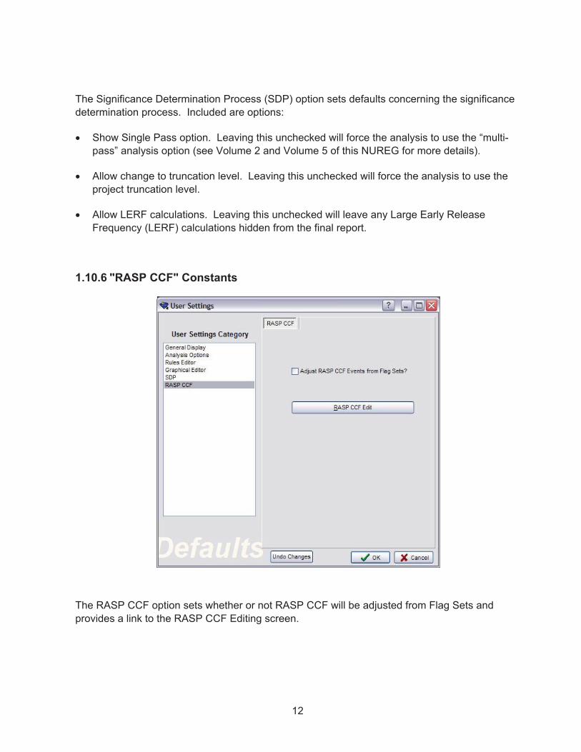
1.10.6 "RASP CCF" Constants
The RASP CCF option sets whether or not RASP CCF will be adjusted from Flag Sets and provides a link to the RASP CCF Editing screen.

13
1.11 User Support
Support for SAPHIRE users, including training, may be obtained by joining the SAPHIRE Users Group. Information on this support mechanism may be found at the internet URL saphire.inl.gov.


15
2. SAPHIRE PROJECTS
This Chapter presents an overview of the SAPHIRE 8 database structure. In SAPHIRE 8, the term “project” represents a single, specific database.
2.1 Opening a Project
If there is not a current project available or a second session of SAPHIRE 8 is started, it will start with an option screen to open an existing project or create a new one. Existing projects can be found through the browsing function or by clicking the Open Existing Project icon.
When SAPHIRE starts with a current project in its memory, it will give the operator an option to modify or perform an analysis on the current project or browse for another project and launch an editing session or analysis with it.
Project (Definition) -
A group of fault tree logic and graphics; event trees and sequences; basic events and related data; cut sets; analysis results; and descriptions.

16
Clicking on Browse or Open Existing Project will open up a window to select the project. The user can also use the File � Open existing project option on the main menu bar at the top left of the screen.
An “Open Project” window will appear. Use the various Window Explorer options to find the folder containing the existing project.
To open the latest version of the project, select and open the *.SRA or FAM.DAT file. Or, to open an archived version of the project, select a *.zip file (note that new to SAPHIRE 8 is the ability to open archived zipped projects).
17
2.2 Creating a New Project
Select the New icon on the startup screen or use the main menu File � New � Project option.A “New Project” window will appear. Type the new project name and (optional) description.
Verify that the Parent Directory is acceptable. If a different parent directory is desired, click Browse.
Verify that the Folder Name is acceptable. By default, the Folder Name matches the project Name. (If the Folder Name appears blank, move the cursor out of the project Name field so that the Folder Name can update.)
Click OK. The main SAPHIRE menu will be displayed and the project name and the project location will be shown in the title bar above the menu.

18
2.3 Project Folder Structure
Each SAPHIRE 8 project is contained in a project folder. Inside that folder, subfolders are used to manage the database information. Included in the subfolders are:
� INIs – This folder stores .ini files related to project settings (e.g., bookmarks, general user settings).
� Mard – This folder stores any MAR-D files that are exported from SAPHIRE 8.
� Publish – This folder stores any report files that are exported from SAPHIRE 8.
� Shared – This folder contains information this is shared among the main project and all workspaces. For example, project-related diagrams are stored in the “Diagrams” subfolder. By sharing this information in a central place, the shared information is not duplicated each time a new workspace is created.
� Temp – This folder is used by SAPHIRE 8 during analysis. No project information files should be stored in this folder.
� Workspaces – This folder is used to store all Workspaces that are saved.

19
3. MODEL EDITING
This chapter covers navigation of the model creation and editing functions and the use of the lists panel.
3.1 SAPHIRE Model Development Area
Creating and modifying the base reliability model for a project database is performed in windows opened up in the model development area which is where the gem graphic is. The various Fault Tree, Event Tree, and Basic Event screens opened up in the Model Development area will open with their own main menu and title bar, such as the event tree one here:
3.1.1 SAPHIRE Window Management
The various windows opened in the Model development area can be managed through sizing and storing for ease of use and quick retrieval.
3.1.2 Sizing a Window
Most SAPHIRE 8 dialogs and windows can be resized by dragging its edges until it is the desired size. Windows may be maximize and minimize as needed.
A SAPHIRE specific button is available next to the minimize and the maximize
buttons on the title bar. Click to automatically resize and reposition the window so that the window fits within the main SAPHIRE window immediately to the right of the Lists Panel (see Section 3.2), effectively covering the SAPHIRE graphic on the main window.
3.1.3 Open Windows
In SAPHIRE 8, multiple windows can be open at the same time. This includes multiple windows of the same type. For example, two different fault tree editor windows can be open at the same time, as well as several basic event editors. In addition, objects may be dragged-and-dropped between two open fault tree windows.
Every window that is open appears in the “Open Windows” list on the Lists Panel and is grouped according to the type of window it is. Click on an item in the “Open Windows” list to bring that window to the front of the others. This will restore a window if it has been minimized.

20
3.2 Lists Panel
The main screen of an opened project contains a resizable panel of “object” lists along the left side of the window. This panel is connected to the left side of the main window, but the right border of the panel can be stretched to shrink or increase the width of the panel as needed.
Press the button to collapse a list, and to expand it.
The lists that appear in the panel may be hidden/shown by toggling the check marks next to the different list types in the View option available on the main menu. For example, to display the End States list in the List Panel, choose View � End States, and make sure a check box appears next to the End States menu option. To remove the End States list from the List panel, choose View � End States and make sure a check box does NOT appear next to the Basic Event menu option. The analysis areas in SAPHIRE 8 are contained in “workspaces” which may be shown via the View option. For additional details on Workspaces, refer to the Volume 5
of this NUREG series.
3.2.1 List Filters
The “Basic Events”, “Fault Trees”, and “Event Trees” lists contain a drop down list of filters next to their list labels. For fault tree and event tree lists, options include the “All”, “Main Trees”, or “Sub Trees” filters to display only the trees in the list that meet the filter criteria. For basic
events, several filters are available, such as Initiators, Templates, Compound, and House. The “Standard” filter displays all available events that would normally be used in fault tree modeling, and excludes “helper” events such as template, system generated, developed, and value events.
3.2.2 Selecting from a List
One or more items can be selected from each list for processing. An item in a list is selected if it is highlighted. There are various ways to select items from a list:
� To select a single item, click with the left mouse button on the desired item and let go of the mouse button.
� To select multiple continuous list items, click with the left mouse button the on first desired item, then while holding down the Shift key, click the last desired item.
TIP:
It is important to remember that even though all the items in the lists boxes may not appear in the list (for example, if a filter is selected), they still exist in the database.

21
� To select multiple non-continuous items in the list, click several items while holding down the Control key.
� To select all items in the list, hold down the Control key and press “A”.

23
4. BASIC EVENT EDITING
This chapter introduces SAPHIRE basic event data entry and basic event probability calculation types.
4.1 Basic Event Terminology
Unique terms used in SAPHIRE Basic Event editing are discussed below.
� Failure Model – SAPHIRE provides 14 unique calculation types to describe how the basic event succeeds or fails.
� Developed Event – A developed event is an event in SAPHIRE that is either an event tree top or a fault tree gate. Regular fault tree basic events are not considered developed events.
� Delete Term – In SAPHIRE, the process known as “delete term” refers to the removal of sequence success cut sets from the list of failure cut sets when generating sequence cut sets. As an example of the “delete term”, consider a sequence where top event A is successful and top event B is failed. Any cut sets that would fail A should not be allowed in the cut sets for B, so those cut sets are removed from the sequence.
4.2 Modify Basic Events
To enter basic event data, go to the “Basic Events” list on the List Panel.
To add a new event, double click New Basic Event … at the top of the Basic Events list.
To modify data for an existing event, double-click on the event to edit or right-click to invoke the pop-up menu and select Edit Basic Event.
24
4.3 Edit Basic Event Screen
Modifying a basic event displays the “Edit Basic Event” dialog.
The screen consists of name and description textboxes, a template event assignment checkbox with a dropdown list of default templates, and also shows the calculated probability in the upper right.
4.3.1 Basic Event Screen Navigation:
Click on the field to edit. The text will become editable, or a drop down selection box will become available.
To save event changes and close the event window, choose OK.
To save event changes but continue editing the event, choose Apply.
To quit without saving a changed event, choose Cancel.

25
To create a new event based on the characteristics of the displayed event, rename the event and choose Save As New.
4.3.2 Basic Event Name and Description
The name is the fundamental name used in the fault trees and event trees. A unique name must be specified for every basic event in the logic models. A maximum of 24 uppercase, alphanumeric characters may be entered. Embedded spaces are not allowed.
The description is a 120-character, uppercase or lowercase, alphanumeric field that provides brief, descriptive information.
4.4 Basic Event Failure Model
The first tab on the left of the Edit Basic Event dialogue is the Failure Model, as shown above in Section 4.3. The use and capabilities of this tab are discussed below.
4.4.1 Event Default Template
To use another event’s information as a template for this basic event, select the name of the event from the drop-down list. Then check the box next to the desired characteristics to be used by this basic event. By default, all of the template event characteristics are selected and not editable. Other characteristics not in the template can be edited.
4.4.2 Model Type
A basic event has one or more model types. Each model type can have its own description and failure model information. This field is non-editable.
4.4.3 Description
This is the basic event description for this model type. Often it is the same as the basic event’s main description.
4.4.4 Calculated Probability
The calculated probability that will be used for the basic event model type is listed in this field. Note that certain failure models (e.g., initiating events) will not show the probability in the Calculated Probability field, but in the Lambda field of the Failure Model.
4.4.5 Process Flags
Process flags are primarily used to tell SAPHIRE how to solve event tree accident sequences and fault tree logic. The flag set in the model type will cause the basic event to use the logic shown in Table 1 and Table 2 depending on the use of the basic event. If the basic event is used as an Event Tree sequence top, the logic in Table 1 is used. If the basic event is used as a Fault Tree transfer, the logic in Table 2 is used.

26
Table 1. Sequence Top Process Flags.
Sequence Top Flags
BLANK or Default Failure => System Logic
Success => Delete Term
When the Process Flag field is blank, the transfer associated with this event is expanded for failure references. For success branches in an event tree, the transfer is also expanded; however, any impossible cut sets are removed from the results using cut set matching (i.e., the delete term).
I Failure => System Logic
Success => /System Logic
Use system logic (if top event fails), use the complement of the system logic (if top event succeeds). That is, if the top event is a failure, SAPHIRE will expand the fault tree and solve, just as one expects. If the top event succeeds, SAPHIRE will complement the fault tree logic and solve it, thereby resulting in a non-coherent logic solution.
W Failure => System Logic
Success => /Developed Event
Use system logic (if top event fails), use complement of the developed event (if top event succeeds). That is, if the event fails SAPHIRE will expand the fault tree and solve. If the event succeeds, SAPHIRE will treat the top as a basic event (i.e., developed event) and use the complement of the event for the system probability.
X Failure => Developed Event
Success => Delete Term
Use developed event (if event fails), use cut set matching to eliminate cut sets (if event succeeds). That is, an "X" tells SAPHIRE that a basic event is to be used for failure probability, but a success top is to be treated the same as if the flag was blank.
Y Failure => Developed Event
Success => /Developed Event
Use developed event (if event fails), use complement of developed event (if event succeeds). That is, a "Y" indicates that a transfer is to be replaced with its basic event for failed references and the complement of the event is to be used for success tops. If the top event is to be treated as a basic event (both for the up and down branch), then use a “Y” flag for the event.

27
Table 2. Fault Tree Process Flags.
Sequence and Fault Tree Logic Flags
Any value other than "X"
Failure => System Logic
Success => Delete Term
When the Process Flag field is any value other than “X”, the transfer associated with this event is expanded for failure references. For success branches in an event tree, the transfer is also expanded; however, the impossible cut sets are removed from the resulting cut sets using cut set matching (i.e., the delete term).
X Failure => Developed Event
Success => Delete Term
Use developed event (if event fails), use cut set matching to eliminate cut sets (if event succeeds). That is, an "X" tells SAPHIRE that a basic event is to be used for failure probability, but a success top is to be treated the same as if the flag was blank.
4.4.6 Uses Template
To use another event’s information as a template for only this model type, select the name of the event from the drop-down list. For single model projects, use Event Default Template instead.
4.4.7 Failure Model
The Failure Model contains a calculation type selection box. There are 14 unique calculation types identified as 1, 3, 5, 7, V, T, F, I, C, X, S, G, E, and H (see Table 3 for the data entry requirements for each calculation type). Choose the desired calculation type from the drop-down list. See Table 4. "Basic" failure model calculation types and Table 5. “Advanced” failure model calculation types for details on each calculation type.
4.4.8 Failure Model Parameters
When a failure model is selected, the screen will change to display the required input types for that model. These inputs will be tailored to the specific failure model used, for example for calculation type #3, a failure rate and mission time must be specified.

28
Table 3. SAPHIRE failure model (i.e., calculation type) data entry requirements.
Failure Model (Calculation Type)
Parameters
1 Mean Failure Probability
3 Lambda* (per hour.), Mission Time** (hours)
5 Lambda* (per hour.), Tau (hours), Mission Time** (hours)
7 Lambda* (per hour), Tau (hours)
N Frequency
G Median Failure Acceleration, Screening G-Line
H Median Failure Acceleration
V Value
X SPAR-H Diagnosis, Action, and Dependency Parameters
R RASP CCF Properties Edited in model data***
E, S, I None
Notes:
* The time units of lambda, tau, and mission time must be the same so that they cancel (e.g., in time units of either hour or per hour).
** If no mission time is specified (i.e., the mission time is zero), the default mission time specified in SAPHIRE Project � User Settings � General Analysis will be used.
*** See the RASP CCF Module discussion in Volume 2 of this NUREG report.
29
Table 4. "Basic" failure model calculation types.
CalcType
Equation Comments
1 P = p Simply a probability (or, possibly, a frequency in the case of an initiating event). Could represent a failure upon demand.
p = probability, in the “mean probability” field
3 P = 1 – EXP( - � Tm) Failure probability of an operating component without repair (non-demand failure mode)
� = mean failure rate, in the “lambda” field
Tm = mission time, in “mission time” field
5 P = ([� �] / [1 + {� �}]) *
(1 - EXP [-(� + 1/�) * Tm])
Failure probability of an operating component with the possibility of repair following a failure.
� = mean failure rate, in the “lambda” field
� = mean repair time, in the “tau” field
Tm = mission time, in “mission time” field
7 P = 1 + (EXP[-� �] - 1)/(� �) Failure probability of a standby component in a non-demand failure mode that is tested periodically.
� = mean failure rate, in the “lambda” field
� = test interval, in the “tau” field
T P = 1 House event TRUE, represents a failure.
F P = 0 House event FALSE, represents a success.
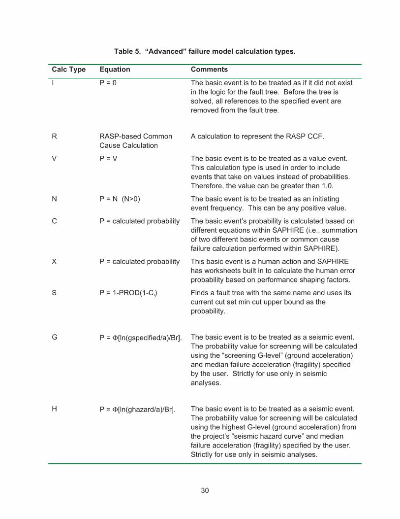
30
Table 5. “Advanced” failure model calculation types.
Calc Type Equation Comments
I P = 0 The basic event is to be treated as if it did not exist in the logic for the fault tree. Before the tree is solved, all references to the specified event are removed from the fault tree.
R RASP-based Common Cause Calculation
A calculation to represent the RASP CCF.
V P = V The basic event is to be treated as a value event. This calculation type is used in order to include events that take on values instead of probabilities. Therefore, the value can be greater than 1.0.
N P = N (N>0) The basic event is to be treated as an initiating event frequency. This can be any positive value.
C P = calculated probability The basic event’s probability is calculated based on different equations within SAPHIRE (i.e., summation of two different basic events or common cause failure calculation performed within SAPHIRE).
X P = calculated probability This basic event is a human action and SAPHIRE has worksheets built in to calculate the human error probability based on performance shaping factors.
S P = 1-PROD(1-Ci) Finds a fault tree with the same name and uses its current cut set min cut upper bound as the probability.
G P = �[ln(gspecified/a)/Br]. The basic event is to be treated as a seismic event. The probability value for screening will be calculated using the “screening G-level” (ground acceleration) and median failure acceleration (fragility) specified by the user. Strictly for use only in seismic analyses.
H P = �[ln(ghazard/a)/Br]. The basic event is to be treated as a seismic event. The probability value for screening will be calculated using the highest G-level (ground acceleration) from the project’s “seismic hazard curve” and median failure acceleration (fragility) specified by the user. Strictly for use only in seismic analyses.

31
E P = 1-PROD(1-Ci) Finds an end state with the same name and uses its cut set min cut upper bound as the probability
Notes: � = standard normal cumulative distribution function
a = median failure acceleration (the approximate ground acceleration sufficient to cause the component to fail)
Br = amount the failure acceleration "a" can vary
g = ground acceleration for screening
4.4.9 Uncertainty Distribution
For each failure model input, an associated uncertainty distribution can be defined. There are thirteen predefined distribution types available:
Beta, chi-squared, constrained non-informative, Dirichlet, exponential, gamma, histogram, lognormal, maximum entropy, normal, seismic lognormal, triangular, and uniform.
In addition to these predefined distribution types, user-defined histograms may be used. For information on how histograms are defined, refer to Volume 2 of this NUREG report.
The default distribution type is Point Value (i.e., it is a point estimate). Choose the desired distribution type from the drop-down list. The screen will change to display the required input types for the selected distribution type.
4.4.10 Correlation Class
Use to account for data dependencies among like events in the database. Enter up to four uppercase, alphanumeric values. A blank correlation class indicates that there are no data dependencies. When running the uncertainty analyses, the same sample value will be used for all basic events with the same correlation class.
4.5 Basic Event Attributes
Each basic event has special attributes that delineate the type of event. The Attributes tab opens the dialogue for setting or viewing these attributes.
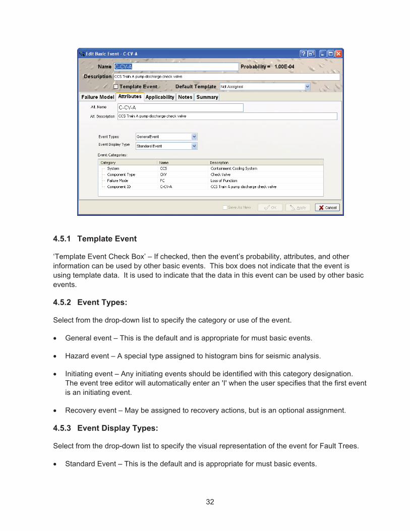
32
4.5.1 Template Event
‘Template Event Check Box’ – If checked, then the event’s probability, attributes, and other information can be used by other basic events. This box does not indicate that the event is using template data. It is used to indicate that the data in this event can be used by other basic events.
4.5.2 Event Types:
Select from the drop-down list to specify the category or use of the event.
� General event – This is the default and is appropriate for must basic events.
� Hazard event – A special type assigned to histogram bins for seismic analysis.
� Initiating event – Any initiating events should be identified with this category designation. The event tree editor will automatically enter an 'I' when the user specifies that the first event is an initiating event.
� Recovery event – May be assigned to recovery actions, but is an optional assignment.
4.5.3 Event Display Types:
Select from the drop-down list to specify the visual representation of the event for Fault Trees.
� Standard Event – This is the default and is appropriate for must basic events.

33
� House Event – This is an event that is either true or false and is usually set by Flag Sets or Change Sets.
� Undeveloped Event – Typically a gate or an event set to a probability of one as a placeholder for an event that will have a failure model assigned in the future.
� Undeveloped Transfer – This is another placeholder event that is a transfer event that has not been assigned a tree to transfer to yet.
4.5.4 Event Categories
Optional event categories can be defined for the project through MAR-D download or manually entered through Project � Categories. These categories are used in SDP Workspace. If event categories have been defined for the project, click on the “Name” column for each category and select the desired value.
In the SDP Workspace, the first step of the analysis is to select components to be evaluated. Components are grouped by their system designation (e.g., CCS is the containment cooling system). The second step in the analysis is to modify specific failure modes for selected components – these failure modes are identified via the Failure Mode Category. Lastly, basic events may be “assigned” to a component via the Component ID Category – this is the linkage mechanism by which SAPHIRE knows that one or more basic events are assigned to a “component.”
4.6 Basic Event Applicability
The Applicability tab opens the dialogue to select the applicable model types and phase(s). By default only one model type is selected. If more than one model type or a Phase is selected, “Failure Model” data that is separately applicable to each model type must be entered.

34
4.7 Basic Event Notes
The Notes tab allows entry of notes and references related to the basic event.

35
4.8 Basic Event Summary
The Summary tab provides a summary of the basic event, including uncertainty (if uncertainty parameters have been specified).

36
4.9 Template Events
Template events are basic events that can be shared. For example, if a PRA contains 15 individual motor operated valve (MOV) basic events that fail due to leak, one can refer to a single template MOV-LK instead of typing the MOV failure rate 15 times. Template events can be set up so that the event description, failure data, uncertainty data, attributes, and/or process flags can be used multiple times.
To create a template event, double click on New basic event in the Basic Events window to open the Basic Event form.
� Input the basic event description, failure data, and uncertainty data that are associated with this template.
� To make SAPHIRE use this event as a template event, select the Template Event check box (see Figure 3).
Figure 3. Setting up a basic event to be a template event
Now, click the Attribute tab. Then, indicate which information is to be shared by this template event. If a box is checked in the Available For Use then that information will be shared, otherwise, the description, event types and display types can be different in the event using the template information from what is specified here and only the failure model information is shared.

37
To use a template event:
� Open the basic event edit window that will use the template event. (In this case, basic event C-MOV-A was selected).
� The template can be assigned by either clicking on the Default Template down arrow or the Uses Template down arrow to list all of the template events in the database. Select the applicable template event (Figure 4).
Note:
One generally does not want to share the description since the events that use the template will have (possibly) unique descriptions.
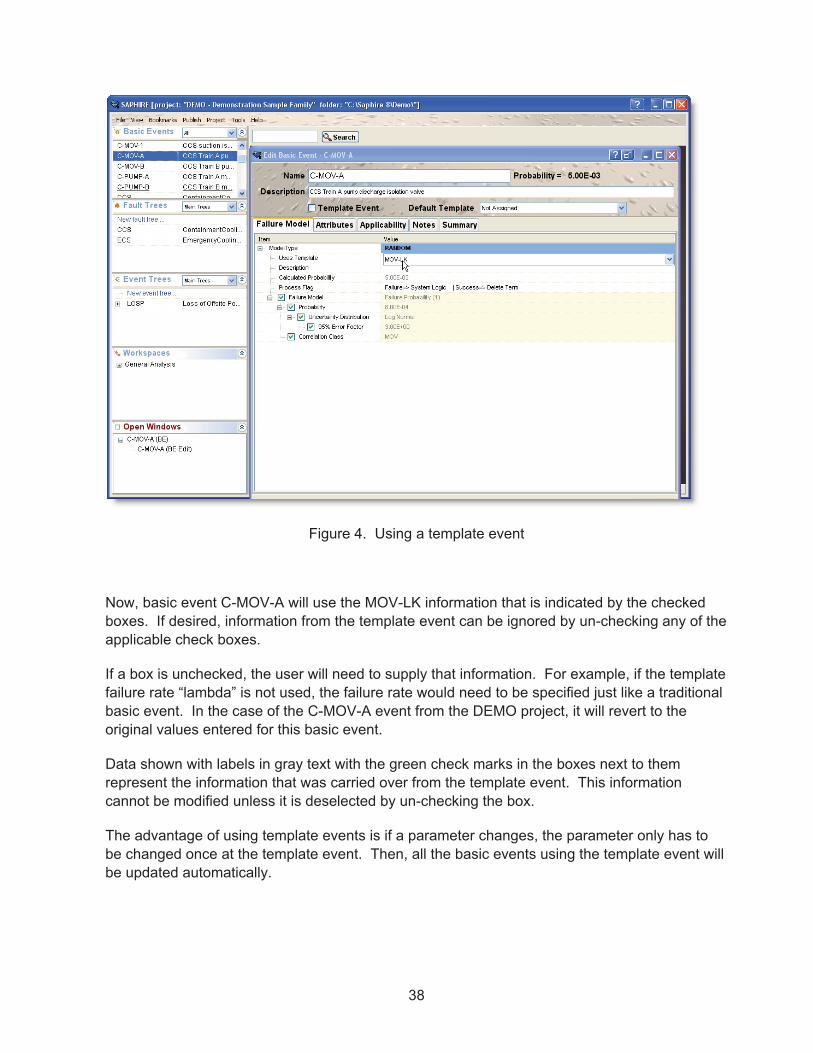
38
Figure 4. Using a template event
Now, basic event C-MOV-A will use the MOV-LK information that is indicated by the checked boxes. If desired, information from the template event can be ignored by un-checking any of the applicable check boxes.
If a box is unchecked, the user will need to supply that information. For example, if the template failure rate “lambda” is not used, the failure rate would need to be specified just like a traditional basic event. In the case of the C-MOV-A event from the DEMO project, it will revert to the original values entered for this basic event.
Data shown with labels in gray text with the green check marks in the boxes next to them represent the information that was carried over from the template event. This information cannot be modified unless it is deselected by un-checking the box.
The advantage of using template events is if a parameter changes, the parameter only has to be changed once at the template event. Then, all the basic events using the template event will be updated automatically.
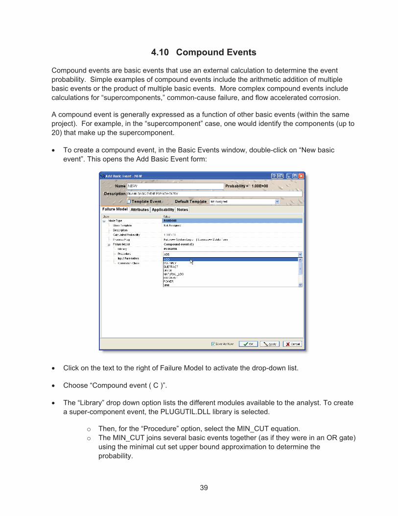
39
4.10 Compound Events
Compound events are basic events that use an external calculation to determine the event probability. Simple examples of compound events include the arithmetic addition of multiple basic events or the product of multiple basic events. More complex compound events include calculations for “supercomponents,” common-cause failure, and flow accelerated corrosion.
A compound event is generally expressed as a function of other basic events (within the same project). For example, in the “supercomponent” case, one would identify the components (up to 20) that make up the supercomponent.
� To create a compound event, in the Basic Events window, double-click on “New basic event”. This opens the Add Basic Event form:
� Click on the text to the right of Failure Model to activate the drop-down list.
� Choose “Compound event ( C )”.
� The “Library” drop down option lists the different modules available to the analyst. To create a super-component event, the PLUGUTIL.DLL library is selected.
o Then, for the “Procedure” option, select the MIN_CUT equation. o The MIN_CUT joins several basic events together (as if they were in an OR gate)
using the minimal cut set upper bound approximation to determine the probability.

40
� Next, click on the “Add Event” button to the right of “Input Parameters” to add the number of Sub Events desired.
� Click on the event field to the right of each Sub Event to activate the drop-down menu of all events in the project. Select an event by clicking on it.
As events are added, SAPHIRE 8 calculates the probability that will be used for the compound event and displays it to the right of the Name of the event.
4.11 Common-Cause Failure Compound Events
Common cause failure (CCF) basic events are used to represent simultaneous failures of multiple components due to a single cause or mechanism. The common-cause basic event represents a model that calculates the probability of a shared cause failing multiple trains of similar components.
Within SAPHIRE, there are two basic types of common-cause models.
� Older-style compound event � New Risk Assessment Standardization Project (RASP) CCF

41
Each of these types are able to use one of two common-cause models. The first is known as the Multiple Greek Letter (MGL) method. The second is known as the Alpha Factor method.
4.11.1 Multiple Greek Letter (MGL) method (old approach)
To use the MGL model in SAPHIRE, under the Basic Events window, double-click on “New basic event …. “
In the dropdown list to the right of Failure Model, select Compound event ( C ).
� Enter the proper number event group for the common cause failure (i.e. TwoEventGroup for a group of two components failing due to common cause).
� Enter a failure count equal to the number of component failures that would cause a group failure.
� Select the basic event from the drop down list to the right of each CCFEvent.
� Select the Beta Factor for the MGL Calculation. This may have to be created as a basic event (value event) to be available for selection.
The advantages of using the MGL equation built into SAPHIRE are:
� Automatic calculation of the nominal common-cause failure probability
� Utilization of the uncertainty defined for the independent events.
� SAPHIRE automatically adjusts the common-cause probability if an independent event is set to a failed state.
4.11.2 Alpha Factor method (old approach)
The second common-cause model is the Alpha Factor model. In SAPHIRE, this model uses one of two different equations, depending on the type of testing for the components in question.
� Staggered testing scheme. � Non-staggered testing scheme.
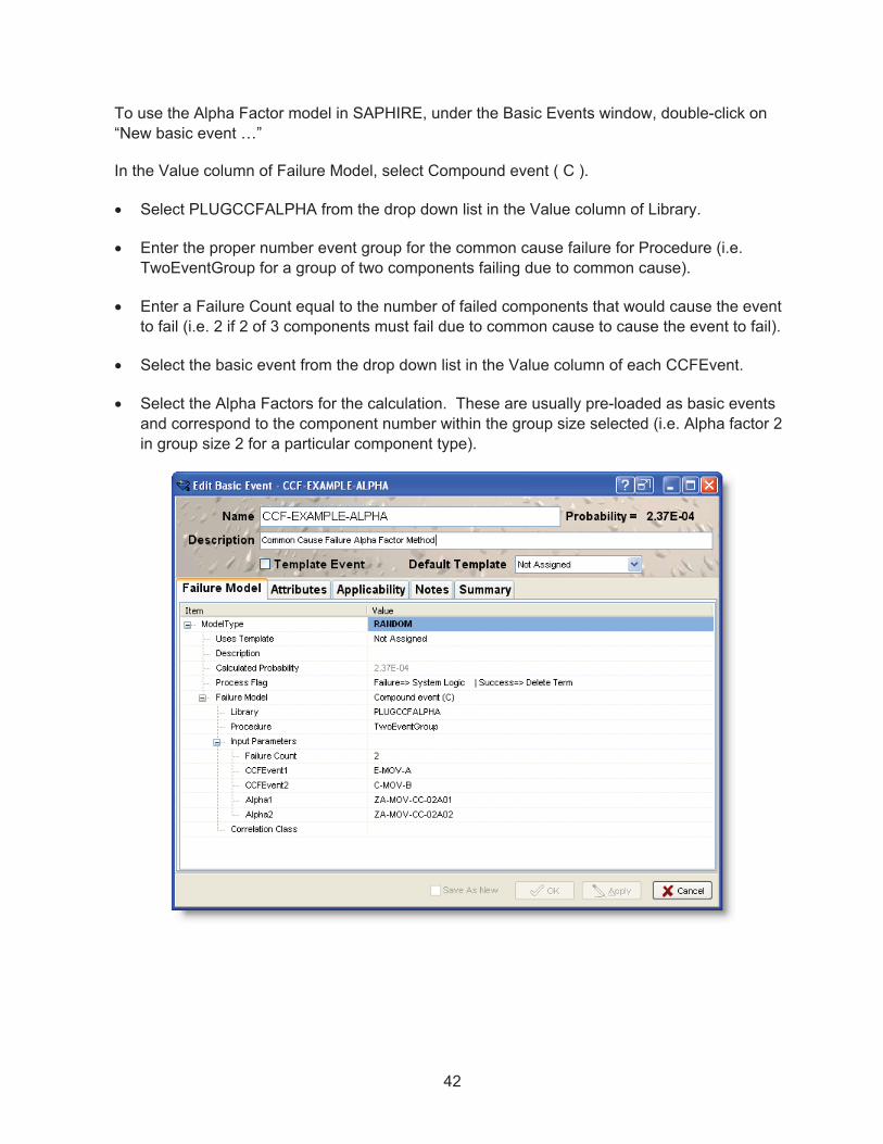
42
To use the Alpha Factor model in SAPHIRE, under the Basic Events window, double-click on “New basic event …”
In the Value column of Failure Model, select Compound event ( C ).
� Select PLUGCCFALPHA from the drop down list in the Value column of Library.
� Enter the proper number event group for the common cause failure for Procedure (i.e. TwoEventGroup for a group of two components failing due to common cause).
� Enter a Failure Count equal to the number of failed components that would cause the event to fail (i.e. 2 if 2 of 3 components must fail due to common cause to cause the event to fail).
� Select the basic event from the drop down list in the Value column of each CCFEvent.
� Select the Alpha Factors for the calculation. These are usually pre-loaded as basic events and correspond to the component number within the group size selected (i.e. Alpha factor 2 in group size 2 for a particular component type).

43
4.11.3 RASP Common-Cause Failure Module
This CCF module uses Boolean reduction to realize combinations of CCF basic events, and removes approximations made in the older conditional CCF probability modeling for events assessment as a result of setting components’ failure modes to 1, T, 0, or F.
This common cause method is a new calculation type to SAPHIRE 8. The common cause failure type “R” can be found in the basic events under the “Failure Model” option.
To demonstrate the CCF module, a new CCF object will be created. A system will be modeled of three redundant motor operated valves (MOVs), represented by basic events MOV-CC-A, MOV-CC-B, and MOV-CC-C. The success criterion for this system is that two components have to work for the system to work. Consequently, if two (of three) components fail, the system is failed.

44
The basic event representing CCF will be called CCF-RASP-2OF3. The fault tree representing the system is shown below.
4.11.3.1 Entering CCF Data into RASP CCF Module The basic event RASP-CCF is a part of the fault tree graphic as shown. However, RASP-CCF is a basic event and must be edited. Clicking on the “Edit” bar will open the editing screen on the Model Data tab of the Basic Event with its CCF Data tab active. Perform the following to set up the RASP CCF event:
� Choose Alpha factors or MGL as the model type from the pull-down menu.
� Click and drag the desired Basic Events into the Independent Failure Events window
� Click and drag the MGL or Alpha factors, which are found in the Basic Events list for models such as SPAR models through MAR-D download covered in Section 10.3. Alpha factors were used in this sample. The Alpha factors need to be entered up to the number of components in the group (1 of 3, 2 of 3, and so on); the naming convention of which shows the number of components in the system first followed by the number of components failed second.
� Choose the number of failures that would cause a system failure. In this case it would be 2.
� The testing scheme can be chosen as Staggered or Non-Staggered

45
� The Separator character is used by SAPHIRE to determine the “auto generated” event names, as we will see when describing the results of the CCF calculation.
� Choose the Results Detail Level
� Rolled Up will create one cut set with the probability posted.
� Full Detail will create cut sets for all combinations of at least 2 of 3 failures.
The probability displayed is the “Rolled-up” probability meaning the overall CCF probability returned by this object. In this example, the overall CCF probability is 2.696E-5.
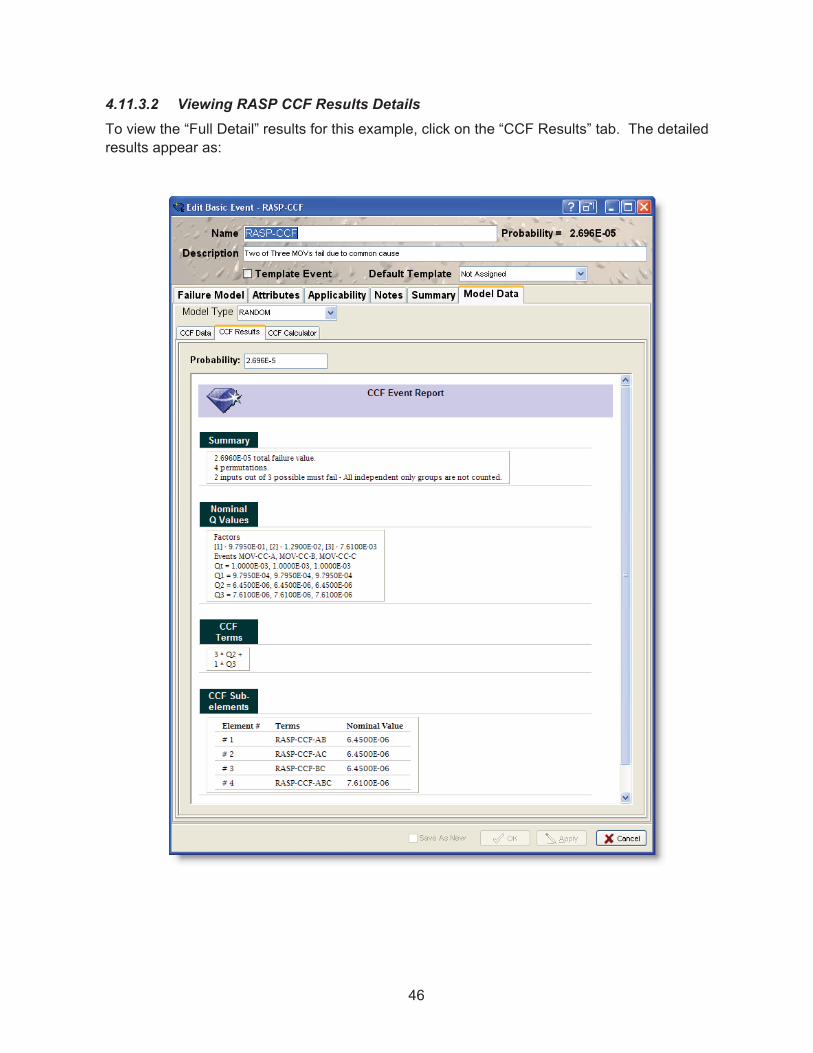
46
4.11.3.2 Viewing RASP CCF Results Details To view the “Full Detail” results for this example, click on the “CCF Results” tab. The detailed results appear as:

47
4.11.3.3 Evaluating RASP CCF Results in detail
The calculated total CCF failure rate is followed by a line is indicating how many CCF terms we are accounting for in the CCF calculation. The last line in the summary indicates that two of three components have to fail to have failure of this part of the fault tree. Also, that a term with ALL independent failures are not counted in the CCF probability.
These lines represent the Q1, Q2, and Q3 terms in the CCF basic parameter model used by the calculation.
These lines indicate that we see three combinations of Q2 terms, and only one Q3 term. Consequently, for this example, the full expression to determine the CCF probability is given by:
P(CCF) = 3 * Q2 + Q3 = 3 * 6.45E-6 + 7.61E-6 = 2.696E-5 .
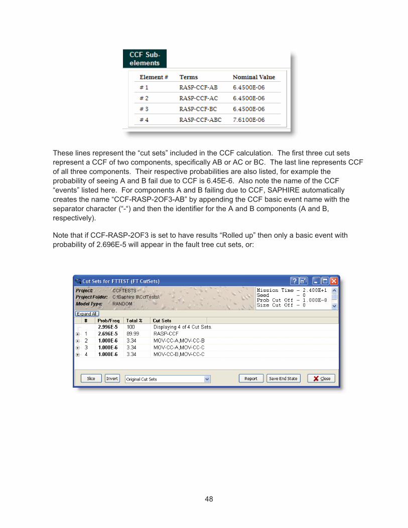
48
These lines represent the “cut sets” included in the CCF calculation. The first three cut sets represent a CCF of two components, specifically AB or AC or BC. The last line represents CCF of all three components. Their respective probabilities are also listed, for example the probability of seeing A and B fail due to CCF is 6.45E-6. Also note the name of the CCF “events” listed here. For components A and B failing due to CCF, SAPHIRE automatically creates the name “CCF-RASP-2OF3-AB” by appending the CCF basic event name with the separator character (“-“) and then the identifier for the A and B components (A and B, respectively).
Note that if CCF-RASP-2OF3 is set to have results “Rolled up” then only a basic event with probability of 2.696E-5 will appear in the fault tree cut sets, or:

49
However, if “Full Detail” results are selected, the results will show all of the combinations of the CCF terms, or:
4.11.3.4 RASP CCF Calculator Tool The “CCF Calculator” tab allows one to change the make-up of the CCF calculation without saving anything in order to try different values of component failure models or probabilities and different alpha or MGL factors and see the results.

50
4.11.3.5 RASP CCF Equivalent Fault Tree Logic By having all of the detail from the CCF, the fault tree calculation is equivalent to having the fault tree logic as shown in the fault trees below:
4.12 Human Error Event
Human error events are basic events that use an external calculation (via worksheets) to determine their probability. The human error probability (HEP) calculation is based on the
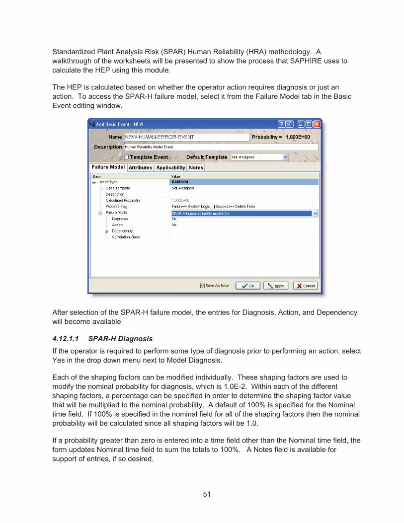
51
Standardized Plant Analysis Risk (SPAR) Human Reliability (HRA) methodology. A walkthrough of the worksheets will be presented to show the process that SAPHIRE uses to calculate the HEP using this module.
The HEP is calculated based on whether the operator action requires diagnosis or just an action. To access the SPAR-H failure model, select it from the Failure Model tab in the Basic Event editing window.
After selection of the SPAR-H failure model, the entries for Diagnosis, Action, and Dependency will become available
4.12.1.1 SPAR-H Diagnosis If the operator is required to perform some type of diagnosis prior to performing an action, select Yes in the drop down menu next to Model Diagnosis.
Each of the shaping factors can be modified individually. These shaping factors are used to modify the nominal probability for diagnosis, which is 1.0E-2. Within each of the different shaping factors, a percentage can be specified in order to determine the shaping factor value that will be multiplied to the nominal probability. A default of 100% is specified for the Nominal time field. If 100% is specified in the nominal field for all of the shaping factors then the nominal probability will be calculated since all shaping factors will be 1.0.
If a probability greater than zero is entered into a time field other than the Nominal time field, the form updates Nominal time field to sum the totals to 100%. A Notes field is available for support of entries, if so desired.

52
The probability is continually updated and shown on the top of the screen in order to show the analyst how the shaping factors are affecting the HEP.
Note:
The X Calculation Type (Human Factor Event) is only required if using the SPAR HRA methodology described above. Human error events can also be entered into SAPHIRE using Calculation Type 1 and providing the mean failure probability for the HEP.
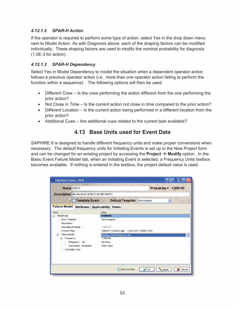
53
4.12.1.2 SPAR-H Action If the operator is required to perform some type of action, select Yes in the drop down menu next to Model Action. As with Diagnosis above, each of the shaping factors can be modified individually. These shaping factors are used to modify the nominal probability for diagnosis (1.0E-3 for action).
4.12.1.3 SPAR-H Dependency Select Yes in Model Dependency to model the situation when a dependent operator action follows a previous operator action (i.e., more than one operator action failing to perform the function within a sequence). The following options will then be used:
� Different Crew – Is the crew performing the action different from the one performing the prior action?
� Not Close in Time – Is the current action not close in time compared to the prior action? � Different Location – Is the current action being performed in a different location from the
prior action? � Additional Cues – Are additional cues related to the current task available?
4.13 Base Units used for Event Data
SAPHIRE 8 is designed to handle different frequency units and make proper conversions when necessary. The default frequency units for Initiating Events is set up in the New Project form and can be changed for an existing project by accessing the Project � Modify option. In the Basic Event Failure Model tab, when an Initiating Event is selected, a Frequency Units textbox becomes available. If nothing is entered in the textbox, the project default value is used.

54
The different frequency units that can be defined in SAPHIRE are:
� not specified � per year � per month � per week � per day � per hour � per minute � per demand
The units specified in Project � Modify will be used no matter what the specified frequency units are for all initiating event. This conversion is performed automatically from the entered values in order to ensure the final sequence results are in the same units.
SAPHIRE will look at the units, if specified for the initiating event, prior to converting the frequency to the units specified in the Project � Modify. This check is performed to guarantee correct conversion.
If the “Unknown” frequency units are specified in the Project � Modify, then the units specified for the initiating events will be used. (One must be careful, since different units can be specified on individual initiators and the overall summation of the sequences may not be correct).

55
5. BUILDING FAULT TREES
This Chapter introduces fault tree development, SAPHIRE fault tree symbols, and SAPHIRE fault tree modeling conventions, and the fault tree graphical editor.
5.1 Fault Tree Development
Fault tree development in SAPHIRE is accomplished through graphical representation. Generally, Fault Tree analysis is defined as:
Fault Tree Development Process
Fault Tree Definition:
Fault tree analysis is a deductive failure analysis method which focuses on identifying all of the credible ways that can cause an undesired event to occur. The undesired event is stated at the top of the fault tree. The fault tree gates specify the logical combinations of basic events that lead to the top event.

56
5.2 SAPHIRE Fault Tree Terminology
Some key terms used in Fault Tree development are:
� Nodes – Nodes are entries into the fault tree which consist of gates and basic events.
� Gates – Gates are action nodes. Their output is based on the inputs received from other nodes or they transfer to another fault tree or a different part of the current fault tree.
� Basic Events – Basic Events are probabilities of occurrence of actions or conditions. SAPHIRE 8 has many model options for basic events.
5.3 SAPHIRE Fault Tree Conventions
Conventions used in SAPHIRE Fault Tree development include:
� Fault Tree File Name – The fault tree name must be the same as the top gate name. The fault tree name can be 24 characters long.
� Fault Tree Node Defaults – The default node Style and Size may be modified on the User Settings dialog (Project � User Settings � Graphical Editor).
� Fault Tree Gates – The gate name is limited to 24 characters in length and cannot include spaces. Gates may be duplicated in the tree or among different fault trees as long as the gates are identical. Identical gates are two gates with (1) the same name and (2) the same inputs.
� Basic Event Names – The basic event name is limited to 24 characters in length and cannot include spaces.
� Top Gates – A fault tree "page" or file can have only one top gate and the top gate must be the same name as the fault tree name.
� SAPHIRE Default Naming – SAPHIRE will automatically assign basic event names (BASIC-EVENT-event#) and gate names (FAULT-TREE#-gate#); however, the user will typically want to replace the default name.
� Transfer Fault Trees – A fault tree can transfer to another fault tree by using transfer gates. The transfer gate name and the “transfer to” gate name must be the same. The gate being transferred to must either be on the same page (internal) or be the top gate of a separate fault tree file (external).
� Complemented Events – Complemented events can be input into fault trees by right clicking on the event in the fault tree editor, then selecting “complement”. Complemented events can be reverted to normal logic in the same manner.

57
5.4 Opening a New Fault Tree
Double click on the New Fault Tree text at the top of the Fault Trees list to open a new fault tree.
A new fault tree opens with a default OR gate as the top gate.

58
5.5 Basic Event Symbols
The Graphical Toolbar symbol for a basic event is:
By clicking on this button, the cursor will change to the null cursor . The cursor will then
change to the boxed basic event symbol when placed over a gate. Use a left mouse click to add the basic event under the gate. Once the basic event is added, the attributes of the basic event can be changed to one of the various types of basic events described below.
5.5.1 Fault Tree Graphic and Logic Symbols for Basic Events
5.5.1.1 Basic Event A basic event represents a fault such as a hardware failure, human error, or an adverse condition. The standard PRA basic event shape of a circle signifies that the fault event does not require further development. A box is available to provide an area that contains the description of the basic event.
5.5.1.2 Stacked Basic Events Stacked basic events consist of two or more basic events displayed in a fashion that represents a “table” of basic events. SAPHIRE allows up to eight basic events to be stacked within one group under a single gate. After that, an additional group of stacked basic events is created under the same gate. The logic used by the stacked events is dictated by the gate it is connected to in the fault tree. Note that the description for each basic event appears above its name and double clicking on the basic event will bring up the basic event editor as discussed in Section 4.

59
5.5.1.3 Undeveloped Event The undeveloped event denotes a basic event that is actually a more complex event that has not been further developed by fault tree logic. SAPHIRE treats this event no differently than a basic event.
5.5.1.4 House Event The house event denotes a failure that is guaranteed to occur (TRUE) or never to occur (FALSE). Even though any basic event in SAPHIRE can be a house event, the calculation type dictates the analysis behavior (Section 4).
5.5.1.5 Undeveloped Transfer The undeveloped transfer indicates that the event is complex enough to have its own fault tree logic developed elsewhere; however, the event has been treated as a basic event in the present fault tree.

60
5.6 Logic Gate Symbols
Graphical toolbar symbols for different gate types with corresponding cursors.
AND Gate OR Gate N/M Gate Transfer Gate
By clicking on an icon, the cursor will change to a null cursor . The cursor will change to the boxed gate symbol that represents the gate selected when placed over a valid insertion location (i.e. over a gate). Use a left mouse click to insert the gate. Once the gate is inserted into the drawing it can be edited to one of the various types of gates described below.
Complements of gates, such as NAND and NOR, are first added as the standard gate, then changed by right clicking and then clicking “complement” from the menu. Conversion of complemented gates to non-complemented gates is discussed in the NAND and NOR gate definitions below.
5.6.1 Fault Tree Graphic Symbols for Gates
5.6.1.1 AND Gate All inputs to the AND gate must occur for failure to occur. Text symbols used to represent an AND gate include � and *.

61
5.6.1.2 OR Gate Any one input to the OR gate will cause failure to occur. Text symbols used to represent an OR gate include � and +.
5.6.1.3 N/M Gate This gate states that N of the M input events must occur for failure to occur. For a 2-of-3 gate, any combination of 2 of the 3 input events must occur.
5.6.1.4 Transfer Gate This gate is used to link logic structures together without introducing any new logic of its own. The transfer gate indicates that logic is continued on a new page (or on the same page). The transfer gate name is the same as the gate name where the logic continues. When transferring to another page (a separate fault tree file), the gate being transferred to must be the top gate on the page. (Note that a top gate name must be the same as the fault tree name. Thus, the transfer gate name must be the same as the fault tree name.)
5.6.1.5 NOT AND (NAND) Gate The output occurs if any one of the inputs does not occur (see example below). A NAND gate is converted into regular (non-complemented) logic by first complementing each input (A � /A) and then changing the gate to an OR gate. Note in SAPHIRE that the “/” indicates a complemented event.

62
5.6.1.6 NOT OR (NOR) Gate The output occurs if none of the inputs occur (see example below). A NOR gate is converted into regular (non-complemented) logic by first complementing each input (A � /A) and then changing the gate to an AND gate. Note in SAPHIRE that the “/” indicates a complemented event.
Connecting lines are drawn automatically between the basic events and gates.
5.6.1.7 Inhibit Gate The inhibit gate was a special type of AND gate available in SAPHIRE 7. This specific graphical shape has been deprecated in SAPHIRE 8. Note though that any inhibit gates in a SAPHIRE 7 project is automatically converted into a respective AND gate in SAPHIRE 8 with the respective conditioning event correctly modeled under the AND gate.
5.6.1.8 Deleting Logic Gates or Events To delete a gate or event, right click the gate or event and choose the Delete pop-up menu option. All of the “child” gates and events (those that are inputs to the selected item) are deleted with the selected item.

63
5.7 Fault Tree Main Menu
The fault tree main menu provides functions for editing and adjusting the view of the fault tree.
5.7.1 File
Save – Saves the fault tree as it is currently configured
Save As… – Save the fault tree as it is currently configured as a different name
View Expanded Model Types – Adds all of the different phases’ events on one fault tree for review, but not modification.
Import Logic – Load a fault tree file into the current fault tree
Export Logic – Save the current fault tree as a .ftl MAR-D file.
Export Image – Save the fault tree image as a .bmp or .wmf file.
Page Setup – Set up a page for printing the fault tree to
Print – Print the fault tree
Exit – Close the fault tree
5.7.2 Edit
Properties – Change properties such as the name, description, or the flag set assigned to the fault tree
Undo – Removes the last action taken on the fault tree
Cut – Cut the selected item from the fault tree and save to clipboard
Paste – Paste the item in the clipboard to the fault tree gate
Paste As – Paste the item as a different name
Complement – Treat the event as its probability complement
Select All – Does just that, selects all items
Move To Transfer – Choose a transfer gate to move the selected item to
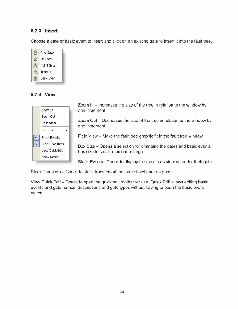
64
5.7.3 Insert
Choose a gate or basic event to insert and click on an existing gate to insert it into the fault tree.
5.7.4 View
Zoom In – Increases the size of the tree in relation to the window by one increment
Zoom Out – Decreases the size of the tree in relation to the window by one increment
Fit in View – Make the fault tree graphic fit in the fault tree window
Box Size – Opens a selection for changing the gates and basic events box size to small, medium or large
Stack Events –Check to display the events as stacked under their gate
Stack Transfers – Check to stack transfers at the same level under a gate
View Quick Edit – Check to open the quick edit toolbar for use. Quick Edit allows editing basic events and gate names, descriptions and gate types without having to open the basic event editor.

65
5.8 Zooming
To enlarge or shrink the view of the fault tree, use the zoom toolbar options, or choose the equivalent option from the main menu.
Toolbar option Menu equivalent Function
View � Zoom In Enlarge the scale of the drawing by a step.
View � Zoom Out Reduce the scale of the drawing by a step.
(none) Enlarge or reduce the scale of the drawing to the step value selected combo box, where 100% is considered normal.
View � Fit In View Size the drawing so that the entire drawing is visible in the window
Use the scroll bars to change the portion of the diagram displayed in the window.
5.9 Ending the Fault Tree Editing Session
To save the event tree, from the Fault Tree Editor menu bar choose File � Save.
To save a duplicate of the tree, use File � Save As and enter the name and (optional) description of the event tree as directed. Designate the event tree as a main or sub tree.
To exit without saving, from the Fault Tree Editor menu bar choose File � Exit.Choose No to quit without saving.

66
5.10 Example Fault Tree
Below, the DEMO project CCS Fault Tree is shown with basic events “stacked.” Note the shading between the basic events to help differentiate between events (e.g., C-CV-A and C-MOV-A).
Now, shown below is the same DEMO CCS Fault Tree (“medium-sized” gates) with basic events shown “unstacked.” Note how stacking (shown above) greatly increases the fault tree readability.

67
6. BUILDING EVENT TREES
This Chapter introduces event tree terminology and SAPHIRE event tree modeling conventions. This section also covers how to enter an event tree into SAPHIRE using the graphical event tree editor and also how to edit an existing event tree. It also shows how to customize the visual display of the event trees.
6.1 Event Tree Development
Event trees are developed by starting with an initiating event and branching to the right as various safety functions are questioned for success (up branch) or failure (down branch). Event trees provide a traceable way to perform the following functions:
� Identify accident sequences � Identify essential safety system functions � Quantify sequence frequencies
Event Tree Development Process
Event Tree Definition:
Event trees are logical representations of significant plant responses to initiating events with each sequence resulting in either a safe condition (such as safe shutdown) or an accident condition (such as core damage).

68
6.2 Event Tree Terminology
Some key terms used in Event Tree development are:
� Initiating Event – An initiating event is an operational occurrence (such as a LOCA or transient) which threatens fuel safety and may require safety system response to avoid core damage.
� Top Event – Safety systems (or human actions) intended to respond to the initiating event.
� Branching – A branch underneath a top event indicates success with an up branch and failure with a down branch.
� Pass – When there is no branching beneath a top event, then the top event is not relevant to the particular sequence.
� Sequence – This is the branching path, from initiating event to end state, which is a unique combination of system failures and/or successes.
� End State – This is a group of accident sequences which share certain characteristics, or outcomes, that the analyst delineates. These may be related to ability to perform a safety function or timing of functional failures.
6.3 SAPHIRE Event Tree Conventions
Conventions used in SAPHIRE Event Tree development include:
� Event Tree Names – Event tree names may be up to 24 characters. The event tree name does not have to be the same as the initiating event name.
� Top Event Names – 24 characters allowed.
� Initiating Event – Only one initiating event allowed per event tree.
� OK, @, Success – If the end state column entry is OK, begins with @, or Success, then logic for that sequence will not be developed, and the sequence will not be analyzed.
� Branch – SAPHIRE always uses success for the up branch and failure for the down branch.
� Transfer Trees – An event tree can branch to another event tree by using transfers. The first top event in the transfer tree is ignored by the calling tree.
� Forbidden Characters – The symbols *, ?, \, @, /, and spaces are not allowed in naming SAPHIRE event trees or top events.
An example event tree from the graphical editor is shown in Figure 5.

69
Figure 5. Example graphical event tree
6.4 Beginning an Event Tree Editing Session
6.4.1 Adding a New Event Tree:
Double click “New Event Tree” from the Event Trees list on the List Panel, or choose File �New � Event Tree.
An event tree editor window will open:
Enter the information (e.g., name, description) on the form and click OK, an “empty tree” will appear:

70
6.4.2 Opening an Existing Event Tree:
Double click on the desired event tree in the Event Tree List Panel, or right click and choose Edit Logic from the pop-up menu.
6.5 Inserting Top Events
Insert top event to the left toolbar button
To add a top event to the left of an existing top event, choose the Insert Top to the left button.
Move the null cursor over to the top event box, and the cursor will change to . A left click will insert a new box with the description “New Top Event” and an arbitrary name to the left of the initiating event box. Note that a top event cannot be inserted to the left of the initiating event.
To add additional top events, continue to click on the initiator box or any top event to add additional top events to the left of the clicked box.
Insert top event to the right toolbar button
To add a top event to the right of another top event, choose the Insert Top to the right button.
Move the null cursor over to the top event box, and the cursor will change to . A

71
left click will insert a new box with the description “New Top Event” and an arbitrary name to the right of the initiating event box.
Select toolbar button
When finished adding top events, click on the hand toolbar button to leave Insert mode and enter Select mode. Alternately, right click to exit the insertion cursor.
6.6 Modifying top events
To edit the name and description of a top event or initiating event, right click and choose the Edit option. Or, if in Select mode – not Insert mode – double click a top event to edit. The Edit Top Event window will be displayed.
� Top Event Name – The name of the top or initiating event (maximum of 24 alphanumeric characters).
� Top Event Description – Brief description of the top (maximum of 120 alphanumeric upper and lowercase characters).
Fill in the name and description for the selected Top Event. To assign a top event that already exists in the project to the selected box, select the existing top from the combo box. The corresponding description will be automatically filled in. Press OK to close the Edit window and view the updated event tree drawing.
6.6.1 Deleting a top event
To delete a top event, right click the top and choose the Delete pop-up menu option. (The Delete option will be grayed out if there are branches associated with the selected top. Branches under a top must be removed before deleting the top event.)

72
6.7 Editing Event Tree Branches
Adding up and down branches, adding descriptive text on branch lines and deleting are covered.
6.7.1 Adding event tree branches
To add branches to an event tree, choose the Insert Up Branch or Insert Down Branch toolbar button.
Insert Up Branch toolbar button
Insert Down Branch toolbar button
Select the branch point and the null cursor will change to the appropriate up
branch cursor or down branch cursor , depending upon the toolbar button chosen. A left mouse click will add a new branch in the tree above or below the selected branch.
6.7.2 Deleting branches
To delete an unwanted branch, right click on the unwanted branch point and choose Delete from the pop-up menu.
6.7.3 Adding text to a branch
To attach text to a branch, double click on the branch point , or right click, and choose Edit from the pop-up menu.
TIP:
When a valid branch point is selected, the cursor will change to (arrow with page). Position
the cursor so that the very tip of the arrow is inside the branch point circle .

73
Enter the branch text in the Branch Annotation field and press OK. The text will display above the branch point. The text will stay with the branch as the tree is resized and/or edited.
6.7.4 Expanding and Collapsing branches
To aid the development of larger trees, hide (collapse) portions of the event tree to shrink them. The nodes will still exist, but will not be visible in the editor until they are expanded. This allows
a focus on a particular section of a tree. To collapse a node, while in Select mode (click to get into Select mode if needed), click the symbol that immediately follows the node to collapse. All branching that originates to the right of the node (including sequence/end state
information) will disappear, and in its place will appear .
6.8 Editing Sequence/End State Information
Each sequence path has some additional information that can help define it. This information includes the name of the sequence, the end state of this sequence, its frequency, and a comments field. If the sequence continues through another event tree then the end state field is the name of the transfer tree.
6.8.1 Edit End-State Description
To enter additional information about a sequence, right click on a sequence box and choose the Edit option. The Edit End-State Description dialog will be displayed.

74
End-State Name – The name of the sequence end state. This is limited to 24 alphanumeric characters. If the pop-up menu option Use As Transfer has been selected for this sequence, the name of the transfer event tree is used.
Sequence Name – This is the informational name of the sequence. SAPHIRE will not refer to the sequences elsewhere in the project using this name – it only appears in the logic editor as descriptive information, and is therefore not generally used.
Frequency – Contains the last known frequency for the sequence. SAPHIRE 8 does not automatically update this field as the value becomes available.
Comments – Free-form comments up to the maximum limit of 24 alphanumeric characters.
6.8.2 View Sequence/End State Information
To view or hide each column of information: From the editor’s main menu, toggle the check marks for the following options:
� View � Show Sequence Name � View � Show Frequency � View � Show End-State � View � Show Comment

75
6.8.3 Modifying an End State to be a Transfer
In SAPHIRE, the end state of one event tree may be changed to be a transfer, where the transfer goes to another event tree. To change and End State to a transfer, right click the end state box, and select “Change to Transfer.”
The name of the Transfer will appear in the transfer symbol on the event tree graphic. To change the name of the transfer, double click on the transfer symbol and change the “Name” field.
6.8.4 Disabling an End State
In SAPHIRE 8, sequences with the end state name of OK or success are ignored (i.e., disabled) during cut set solving and quantification. Also, sequences can be disabled by right-clicking an end state and selecting the “Disable End State” option (as shown above). This option will insert an “@” at the start of the end state name, telling SAPHIRE not to solve that sequence. Note that when editing an end state, SAPHIRE does not allow the “@” to be typed into the name of an End State. Also, the OK end state is already "disabled," so attempting to use the "Disable End State" option does not modify that end state.

76
6.9 Editing the Visual Display of Event Trees
6.9.1 Adjust the visual display of the event tree
The size of the top event boxes can be selected to be small, medium, or large by check marking the desired size in the editor’s main menu, View � Box Size.
6.9.2 Zooming
To enlarge or shrink the view of the event tree, use the zoom toolbar options, or choose the equivalent option from the main menu.
Toolbaroption
Menu equivalent Function
View � Zoom In Enlarge the scale of the drawing by a step.
View � Zoom Out Reduce the scale of the drawing by a step.
(none) Enlarge or reduce the scale of the drawing to the step value selected combo box, where 100% is considered normal.
View � Fit In View
Size the drawing so that the entire drawing is visible in the window
Use the scroll bars to change the portion of the diagram displayed in the window.
6.10 Ending the event tree editing session
To save the event tree, from the Event Tree Editor menu bar choose File � Save.
To save a duplicate of the tree, use File � Save As and enter the name and (optional) description of the event tree as directed. Designate the event tree as a main or sub tree.

77
To exit without saving, from the Event Tree Editor menu bar choose File � Exit. Choose No to quit without saving.
TIP:
To rename an event tree or change the description or main/sub tree designation without exiting the editor, choose Edit � Properties.

78

79
7. SOLVING FAULT TREES
Generating cut sets, uncertainty and importance analysis are covered in this section.
7.1 GENERATING FAULT TREE CUT SETS
This section describes how to generate fault tree cut sets. Model preparation prior to generating cut sets is discussed, and the various analysis and truncation options are described. Cut set display features are also presented.
7.1.1 Prerequisites for Generating Fault Tree Cut Sets
Fault tree logic was created by using the fault tree graphics editor, or loaded into the database via the MAR-D interface. Basic event data were added through the Edit Basic Event forms.
Fault tree transfers are properly modeled so that there are no logic loops in the fault trees, there is only one top gate in each fault tree, and the naming of transfer gates and fault tree filenames is consistent.
7.1.1.1 Logic Loop Example

80
The correct way to "break the loop" will depend on which system is being analyzed.
7.1.2 Menus and options for fault tree cut set generation
Use the mouse to select the Fault Tree(s) from the List Panel using the mouse.
Right-click to invoke the pop-up menu.
Select the Solve option.
81
This option uses the fault tree logic from all fault trees that link to the top gate in the system. The fault tree probability is quantified using the minimal cut set upper bound (which is set as the project default).
7.1.3 Truncation Parameters
Select the desired truncation parameters and solution steps on the dialog, and choose Solve to begin generating cut sets.
� Cut Set Truncation – From this combo box, choose one of the following options:
o None – No truncation will be performed. o Global – uses the cutoff value in the adjacent cut off field. This field defaults to
the value set in Project � User Settings � General Analysis� Cut Set Truncation � Fault Tree Value
o System – uses the cutoff value stored with the fault tree record (via the Edit �Fault Tree, Edit � Properties option).
� Size Truncation – This option is generally not used. (Option defaults to None). Available options include:
o Size – Cut sets having more than specified in the adjacent text box will be discarded.
o Zone – Cut sets having more Zone Flagged Events than specified in the adjacent text box will not be retained.
o None – The number of events in a cut set will not affect whether the cut set is retained or discarded.
7.1.4 Solution Steps
Check one or more of the following boxes to indicate which steps should be performed. Options not available (i.e. no recovery rules have been set up) will be grayed out. The steps will be performed in their logic order from top to bottom.
� Solve for Cut Sets – If this box is checked, the fault tree logic will be solved for minimal cut sets using the truncation options specified.
� Apply Recovery Rules – If this box is checked, any recovery rules associated with this fault tree will automatically be applied after the fault tree cut sets have been generated.
� Update / Quantify Cut Sets – When this box is checked, cut sets will be re-quantified using the truncation options specified. This option is useful for eliminating non-minimal cut sets introduced when recovery rules have been applied, or to quickly re-quantify the cut sets when basic event data have been altered

82
� Clear Cut Set Partitions – If this box is checked, the user defined partitions are cleared. Partitions are discussed in the advanced section of Fault Tree solving.
� Apply Partition Rules – Check this box to utilize user defined cut set partitions.
� Copy Cut Sets to Base Case – When this box is checked, cut sets will be saved as the nominal case.
7.1.5 Solve Quantification Methods
When Solve is clicked, the quantification of the cut sets will be performed based on the selections made in the Project � User Settings � General Analysis � Analysis Settings Quantification Method selection as follows:
7.1.5.1 Minimal Cut Set Upper Bound Approximation This calculation approximates the probability of the union of the minimal cut sets for the fault trees. The equation for the minimal cut set upper bound is
where
S = minimal cut set upper bound for the system unavailability,
Ci = probability of the i’th cut set, and
m = the number of cut sets.
Example: If the cut sets for a system are A*B, C, D the system unavailability computed from the minimal cut set upper bound approximation is X = 1 - (1 – A*B)(1 - C)(1 - D). Note that this expression assumes that terms such as “C” represent the probability of basic event C, e.g., Pr(C).
7.1.5.2 Min Max Quantification The Min-Max quantification option quantifies the current case cut sets using the exact probability quantification algorithm. From the example above, the exact system unavailability is
X = (A + B + C) - (A * B + A * C + B * C) + (A * B * C),
with the number of passes in this example being 3, corresponding to the number of pairs of parentheses.
7.1.5.3 Rare Event Approximation This calculation simply sums each cut set as an approximation to the exact fault tree probability. This calculation is generally not used.
S = 1 - (1- C )i=1
m
i

83
7.1.6 Displaying Fault Tree Cut Set Results
Highlight the fault tree in the List Panel that is to be viewed; right-click to invoke the pop-up menu. Then select the View Cut Sets option.
7.1.7 Selecting Fault Tree Cut Sets to View
The fault tree cut sets and minimal cut set upper bound approximations of the fault tree failure probability are now displayed.
To view the basic events in a cut set, click the “+” button for the cut set, or click the Expand AllButton to view the basic events for all cut sets at once.
To find out where the events in the cut set came from, highlight a cut set and click on the Pathbutton.
The Report button from the cut set screen allows a printed cut set report.
The Save End State button allows for storage of the list of cut sets in a user-defined end state.

84
The Slice button allows a filter to the list of cut sets based upon user-specified criteria. For example, if it was desired to show only cut sets that contained DG-A, select the Slice By Eventradio button, check the DG-A event, and press OK.
� The Slice By Cutoff option allows a slice of the list of cut sets according to minimum probability levels (e.g., top X%, top 10 cut sets).
� The Slice By Attributes option allows a slice of the list of cut sets matching a selected list of attributes.
� The Slice By Rules option allows the creation of a rule that will slice the cut sets up into specific groups.
When the slice criteria is applied by pressing the OK button, the cut set screen shows only the cut sets that met the criteria. The tool bar area of the screen displays the total number of cut sets that met the criteria, the probability/frequency for the selected cut sets, as well as the original probability of the unsliced cut sets for comparison purposes. Click on the “ ” to expand the basic events as noted above.

85
The button from the cut set screen allows toggling the displayed cut sets between the list of cut sets that met the Slice criteria, and the ones that did not meet the criteria.
The effects of multiple slices are cumulative, so that further filtering of cut sets that have already been sliced is possible. Use the combo box to select a snapshot of each filter that has been previously applied.
7.2 Analyzing Fault Tree "Sub-trees"
To generate cut sets beginning with a gate below the top gate, all one needs to do is highlight the sub-tree in the Fault Tree list pane, right click and solve as normal. The list pane can sort by sub-trees by clicking on the pull down menu in the Fault Tree list pane and selecting Sub-Trees, which in our example only includes CCS-TRAINS.

86
In this example, cutoff by cut set probability is Global and we solve for the sub tree CCS-TRAINS as illustrated in previous sections. The report is shown below:
Note that DG-B appears in several cut sets when only the CCS-TRAINS sub tree is analyzed. This is because the starting gate is the CCS-TRAINS gate and DG-B is analyzed in the minimal cut sets generated. When the CCS Fault Tree is analyzed, the CCS gate is the starting gate; therefore DG-B appears as a "single" in the cut sets and all combinations of DG-B with other basic events are non-minimal cut sets and they are eliminated.

87
7.3 FAULT TREE UNCERTAINTY ANALYSIS
This section describes uncertainty analysis for fault trees. The concept of performing uncertainty analysis via Monte Carlo or Latin Hypercube sampling is discussed. Uncertainty analysis calculates the variability of a fault tree top event probability resulting from uncertainties in the basic event probabilities. SAPHIRE 8 provides two uncertainty analysis techniques:
� Monte Carlo sampling � Latin Hypercube sampling
7.3.1 Monte Carlo Sampling
Monte Carlo sampling is a fundamental approach. It makes repeated quantifications of the system cut sets using each random variable sampled from the basic event uncertainty distributions. Monte Carlo sampling requires more samples than Latin Hypercube sampling for the same degree of accuracy.
7.3.2 Latin Hypercube Sampling
Latin Hypercube sampling is a stratified sampling technique, with the random variable distributions divided into equal probability intervals. The probability is randomly selected from within each interval. Latin Hypercube sampling may require fewer samples than simple Monte Carlo for similar accuracy; however, it may take longer to generate a random value than for a simple Monte Carlo sample.
7.3.3 Uncertainty Distributions for Basic Events
Basic event distribution types supported by SAPHIRE include:
Distribution Parameter
Beta B in Beta(a, b)
Chi-squared Degrees of freedom
Constrained Noninformative (none)
Dirichlet Beta value of success branch
Exponential (none)
Gamma r in (r)
Histogram Histogram number
Lognormal Error factor
Maximum Entropy Lower and upper end point
Normal Standard deviation
Point Value (Use point estimate value only)

88
Seismic Log Normal Beta r, Beta u
Uniform Upper end point
Triangular Mode, Upper end point
Correlation classes may be specified by the user to identify data (or other) dependencies for basic events using data derived from the same data source. Events in the same correlation class are 100% correlated.
7.3.4 Menus and Options for Performing Fault Tree Uncertainty Analysis
Use the mouse to select a fault tree from the List Panel.
Right-click to invoke the pop-up menu and select View Uncertainty.
The fault tree uncertainty screen will appear with the last calculated (if any) uncertainty results.

89
7.3.4.1 Uncertainty Calculation Values and Results To (re)calculate the uncertainty values, enter the following options and press Calculate (as shown in Figure 6).
� Input the Number of Samples. (A larger number of samples will provide more accurate results but will require more computation time.)
� Enter a value for the random number generator seed or accept the default. Enter zero to obtain a random seed from the system clock.
� Select one of the uncertainty method radio buttons, Monte Carlo or Latin Hypercube.
Figure 6. Uncertainty analysis dialog
OPTIONAL:
To save intermediate sample results to a disk file for review, select an output format from the Intermediate Values combo box, and provide an output file name.

90
7.4 FAULT TREE IMPORTANCE ANALYSIS
This section describes the various fault tree importance measures available in SAPHIRE. Also, the calculations behind the importance measures are discussed.
7.4.1 Fault Tree Importance Measures
Importance measures provide “reliability-worth” information about basic events appearing in the cut sets for a fault tree. Components showing high relative importance may be candidates for either (1) close monitoring to ensure that the component does not degrade over time or (2) design changes to increase the component reliability.
Ratio, Interval and Uncertainty importances are calculated for the highlighted fault tree cut sets.
� Ratio Importance – Fussell-Vesely Importance, Risk Reduction Ratio, and Risk Increase Ratio.
� Interval Importance – Birnbaum Importance, Risk Reduction Interval, Risk Increase Interval.
� Uncertainty Importance – This importance measure provides information about the uncertainty of the component (i.e., those components that will contribute the largest uncertainty to an uncertainty analysis of the selected fault tree cut sets).
7.4.2 Definitions of the Importance Measures
Available importance measures are Fussell-Vesely, Risk Reduction Ratio, Risk Reduction Interval, Risk Increase Ratio, Risk Increase Interval, Birnbaum, and Uncertainty (Standard Deviation).
7.4.2.1 Fussell-Vesely Importance (FV) An indication of the fractional contribution of the basic event to the minimal cut set upper bound. The equation for FV importance (of the i’th basic event) is
FVi = F(i)/F(x)
where
F(i) = minimal cut set upper bound (sequence frequency) evaluated for all cut sets containing the i’th basic event
F(x) = minimal cut set upper bound (sequence frequency) evaluated with the basic event probability at its mean value.
7.4.2.2 Risk Reduction Ratio (RRR) or Risk Reduction Interval (RRI) An indication of how much the minimal cut set upper bound would decrease if the basic event probability were reduced (to a probability of zero, i.e., it never fails).

91
RRR = F(x)/F(0)
RRI = F(x) - F(0)
7.4.2.3 Risk Increase Ratio (RIR) or Risk Increase Interval (RII) An indication of how much the minimal cut set upper bound would increase if the basic event probability were increased (to a probability of 1.0).
RIR = F(1)/F(x)
RII = F(1) - F(x)
where F(x) is the original minimal cut set upper bound
F(1) is the minimal cut set upper bound with the event probability set equal to 1.0.
7.4.2.4 Birnbaum Importance (B) Indicates the sensitivity of the minimal cut set upper bound with respect to a change in the basic event probability.
B = F(1) - F(0)
where F(1) is the minimal cut set upper bound with the event probability set equal to 1.0.
F(0) is the minimal cut set upper bound with the event probability set equal to 0.0.
7.4.2.5 Uncertainty Importance (Standard Deviation) The uncertainty in each input parameter, as expressed through its probability distribution, contributes to the uncertainty in the output parameter of interest (e.g., core damage frequency, loss of mission). The uncertainty importance measure in SAPHIRE quantifies the contribution of each individual basic event’s uncertainty to this total output uncertainty. See Volume 2 of this NUREG series for additional detail.
7.4.3 Importance Menus and Options
Highlight the fault tree in the List Panel; right click to invoke the pop-up menu.
Select View Importance Measures.

92
7.4.3.1 Viewing Importance Measures
After performing the steps in 7.3.3, the importance measures are now displayed.
Click on any column header to sort the results in descending order for the selected importance measure.
To perform uncertainty analysis for the importance measures, click the Sample button, enter the uncertainty sampling options, and press OK. The uncertainty details for each importance type are then available on their respective tab pages.
Choose Check All or click individual check boxes to select events to view on the Plot and Report tabs which generates the report below:

93


95
8. SOLVING EVENT TREES
This Chapter covers linking fault trees to event trees, generating sequence cut sets, sequence cut set analysis, uncertainty and importance analysis.
8.1 Linking Event Tree Sequences
This section describes SAPHIRE event tree linking and process required to link event tree sequences.
8.1.1 Linking Event Trees
"Linking" event trees is the process of generating sequence logic using the event tree graphical files.
The linking set is performed automatically when the event tree is saved from the editor or can be performed by invoking the pop-up menu by highlighting the event trees desired and right clicking, then selecting the Link option.
8.2 Generating Event Tree Cut Sets
This section describes how to generate event tree cut sets. Model preparation prior to generating cut sets is discussed, and the various analysis and truncation options are described. Cut set display features are also presented.
8.2.1 Prerequisites for Generating Event Tree Cut Sets
� Event tree logic was created by using the event tree graphical editor and saved.

96
� Fault tree logic associated with the event tree logic was created using the fault tree graphical editor and saved.
� Basic event data was added through the Modify � Basic Events option.
Note: Fault tree cut sets do not need to be generated prior to generating sequence cut sets.
8.2.2 Menus and Options for Event Tree Cut Set Generation
Highlight one or more event trees and/or sequences in the List Panel using the mouse. Right click to invoke the pop-up menu and select the Solve option.

97
8.2.3 Cut Set Generation Cutoff Values
Enter the desired truncation parameters and solution steps, and choose the Solve button to begin generating cut sets.
� Cut Set Truncation – From this combo box, choose one of the following options:
o None – No truncation will be performed. o Normal – uses the initiating event frequency in determining the cut off truncation
value. This is the standard truncation option. o Conditional – ignores the initiating event value (i.e., assumes it is 1.0) thereby
providing a conditional cutoff value (conditional upon the initiating event occurring).
� Size Truncation – Typically not used.
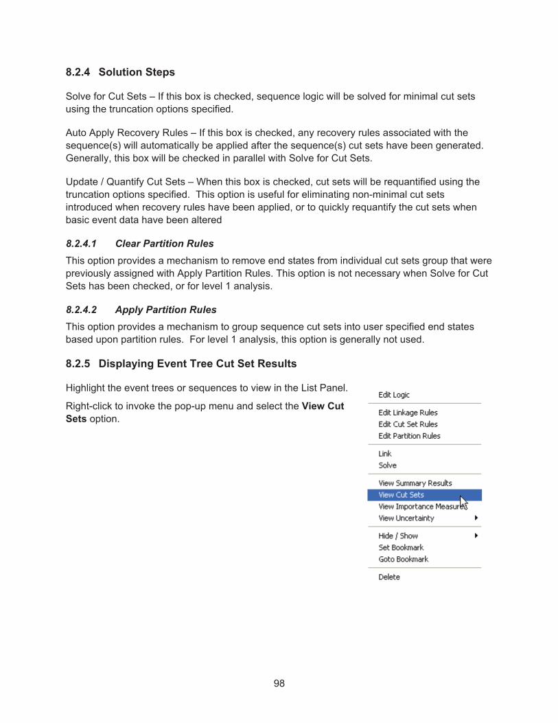
98
8.2.4 Solution Steps
Solve for Cut Sets – If this box is checked, sequence logic will be solved for minimal cut sets using the truncation options specified.
Auto Apply Recovery Rules – If this box is checked, any recovery rules associated with the sequence(s) will automatically be applied after the sequence(s) cut sets have been generated. Generally, this box will be checked in parallel with Solve for Cut Sets.
Update / Quantify Cut Sets – When this box is checked, cut sets will be requantified using the truncation options specified. This option is useful for eliminating non-minimal cut sets introduced when recovery rules have been applied, or to quickly requantify the cut sets when basic event data have been altered
8.2.4.1 Clear Partition Rules This option provides a mechanism to remove end states from individual cut sets group that were previously assigned with Apply Partition Rules. This option is not necessary when Solve for Cut Sets has been checked, or for level 1 analysis.
8.2.4.2 Apply Partition Rules This option provides a mechanism to group sequence cut sets into user specified end states based upon partition rules. For level 1 analysis, this option is generally not used.
8.2.5 Displaying Event Tree Cut Set Results
Highlight the event trees or sequences to view in the List Panel.
Right-click to invoke the pop-up menu and select the View Cut Sets option.

99
8.2.5.1 Display Sequence Cut Sets Once View Cut Sets is selected, as in the previous section, combined cut sets for the selected event tree sequences and minimal cut set upper bound approximation of their frequency are displayed.
To view the basic events in a cut set, click the button for the cut set, or click the Expand All Button to view the basic events for all cut sets at once. The basic events, their failure probabilities and descriptions are now displayed.
� The Report button from the cut set screen allows a printed cut set report.
� The Save End State button allows storage of the list of cut sets in a user-defined end state.
� The Slice button allows a filter to the list of cut sets based upon user-specified criteria.
� The Invert button allows a view of the inverse of the sliced cut sets.

100
� The Show End States radio buttons add the Partition defined mapped end states for multiple level phased analyses and show the end states of the Sequence for single phase models.
8.3 Additional Event Tree Sequence Cut Sets Analysis Features
In complex PRA models, it may be necessary to use special features prior to cut set generation and/or after cut set generation.
� Prior to event tree sequence cut set generation:
� Flag Sets may be used to set House events or Process Flags on a sequence-by-sequence basis.
� After event tree sequence cut set generation:
� Recover Cut Sets can be used as a rule-based automated way to add "recovery events" to the cut sets. These rules are a mechanism of post-processing the cut set list.
8.4 Sequence Uncertainty Analysis
This section describes uncertainty analysis for event tree sequences. The concept of performing uncertainty analysis via Monte Carlo or Latin Hypercube sampling is the same as discussed in Section 7.3 Fault Tree Uncertainty Analysis.
Uncertainty analysis calculates the variability of the sequence frequency resulting from uncertainties in the basic event probabilities and the initiating event frequency.
SAPHIRE provides two uncertainty analysis techniques:
� Simple Monte Carlo sampling � Latin Hypercube sampling

101
8.4.1 Menus and Options for Performing Sequence Uncertainty Analysis
Highlight the desired event tree(s) or sequences from the List Panel.
Right click to invoke the pop-up menu and select View Uncertainty.
If more than one event tree or sequence was selected, choose from the Group By Event Tree(s), Group, or Single Sequence(s) submenu option to specify whether the marked event trees/sequences are to be calculated individually (one at a time), or as one or more groups.
The event tree/sequence uncertainty screen will appear with the last calculated (if any) uncertainty results graphed. If a single sequence or group was selected, a column of result values will also be displayed (shown below).

102
If Single Sequence(s) or multiple Group By Event Tree(s) was selected, a whisker plot summarizing each item will be displayed (shown below). In the case of the DEMO model, the Single Sequence(s) option will show the whisker plots below:
8.4.2 Uncertainty Calculation Values
To (re)calculate the uncertainty values, enter the following options and press the Calculate button.
� Number of Samples – Input the number of samples. (A larger number of samples will provide more accurate results but will require more time).
� Random # Seed – Enter a value for the random number generator seed or accept the default. Enter zero to obtain a random seed from the system clock.
� Uncertainty Method – Specify Monte Carlo or Latin Hypercube.
8.4.3 Uncertainty Results
Press the Results Table button to view individual results (if calculated) and collective results in a tabular format.

103
Uncertainty results (including graph) for each sequence when calculated individually can be also be viewed without having to recalculate:
� Highlight the single sequence in the List Panel. � Right-click to invoke the pop-up menu and select the View Uncertainty option. � The individual sequence uncertainty previously calculated will be displayed and graphed.
Note:
GROUP uncertainty results are displayed only on the screen (as shown earlier in this section), and are not saved for later display.

104
8.5 Viewing Sequence Importance Measures
This section describes viewing importance measures for event tree sequences. A discussion of each type of importance measure is provided in Section 7.4.2.
� Highlight the desired event tree(s) or sequences from the List Panel.
� Right click to invoke the pop-up menu and select View Importance Measures.
� If more than one event tree or sequence was selected, the importance measures will be performed on the group automatically.
� Check the importance measure interested in and sort by any column by clicking on the column header.
Check the boxes of the events interested in and click the Plot button to see a graphical representation of the uncertainty. This step will display the results shown in Figure 7.

105
Figure 7. Illustration of the uncertainty in importance measures
A report that combines the tabular and graphical results can be generated by clicking on the Report tab.


107
9. VIEWING CUT SETS
This section describes the cut set display feature that allows a “slice” of cut sets into different lists based on user-defined sort criteria. The sliced lists may then be viewed or reported. The cut set slicing features is available for fault tree, sequence, or end state cut sets.
9.1 The View Cut Sets Option
The view cut sets option is available in the Fault Tree, Sequence, and End State list menus.
Highlight the desired fault tree, sequences, or end states, right click and select the View Cut Sets option.
As an example, view the cut sets for LOSP sequence 3. It is assumed that cut sets have already been generated (truncation of 1.0E-10).
From the LOSP sequence 3 cut sets, the minimal cut set upper bound approximation frequency is seen as 1.76E-3 and there are a total of 43 cut sets.
Options are available by choosing a radio button at the bottom of the page to display cut set end states with partition definitions or to show the end state at the end of the sequence.
While one or more sequences or end states can be highlighted simultaneously to display their respective cut sets (as a group), only a single fault tree can be selected to display its cut sets. If multiple sequences or end states are selected, all the cut sets from the highlighted sequences or end states will be displayed without eliminating any non-minimal cut sets for the group selected.

108
9.2 The Event Slice Option
The event slice option is used to subdivide the cut sets into two lists. This option allows individual or combinations of desired basic events to appear in the “included in slice” list of cut sets.
With the LOSP sequence 3 cut sets displayed, select Event in the “Slice By” box at the bottom of the cut set display window. A Slice Cut Sets window will be displayed. Select the Events radio button at the top of this form and a list of the basic events will display. Utilize the selection processes found in the following sections to set up the slice and then click on OK to perform the slice.
The Slice Cut Sets editor is very versatile in providing several ways to select events for slicing. The cut sets displayed for selection are controlled by the View Events From drop-down menu.
� Original Cut Sets – This is the default setting and displays just the events from the original solved cut sets for the fault tree, sequence or end state that is being viewed.
� Project – Includes all the events in the project.
� Current Slice – Shows the events that are part of the currently viewed slice.
Individual events can be selected from the list of basic events by clicking on the checkbox of those of interest which enters a check in the box next to the event.
Batch selection of events is accomplished by using an expression in the textbox Regular Expression then clicking to place checkmarks in the checkboxes of the applicable events. Use an asterisk “*” for wildcard searches.
� *PUMP would place a checkbox in all of the events with PUMP in them � E-* would place a check in all checkboxes of events that start with “E-“
Use the buttons and as necessary.
Once the events are selected, Include Type chooses how to include the events.
� Normal – This is the default selection and will include cut sets where the event exists in any manner, failed or complemented.
� Failure – This includes cut set where the basic event is failed.
� Success – This includes only the cut sets where the basic event is in its complemented state, which typically is a success state in SAPHIRE.

109
� NOT – This includes the cut sets where the basic event selected does not exist in any manner.
The OR or AND criteria must be specified for the selected events by selecting the desired radio button. For example, if it was desired to find cut sets that contain any of multiple events selected, use the OR option. Alternatively, if it was desired to just include cut sets that contain every one of the multiple events selected, use the AND option.
At this point, a list of the cut sets meeting the event slice criteria will be displayed along with the quantified probability (or frequency), percent contribution to the total, and the number of cut sets meeting the event slice criteria.
As an example, the results below are for a slice including events DG-A OR DG-B and shows only the cut sets from LOSP sequence 3 that contain either of these basic events.
Expand the cut set by clicking on the icon to the left of the cut set to view events in a single cut set such as cut set #2 in the example above.
� The option allows a copy of the on-screen list of cut sets directly to a user-specified end state for further analysis or storage.
� Click on the button to perform a slice on the currently displayed slice.
� Use the option to show the cut sets that do not meet the current slice’s criteria.

110
� Use the drop down menu to quickly select a view of a slice, inverse, or the original cut sets.
Click on the button to view an .html report of the cut sets.

111
9.3 The Cutoff Slice Option
The cutoff slice option is used to display cut sets where truncation options will be used to parse the overall list of cut sets into two smaller lists. With the LOSP sequence 3 cut sets displayed,
select to open the Slice Cut Sets editor, then select the Cutoff radio button.
� The Top (Cut Sets) option will parse the overall list of cut sets down to only the X number of cut sets specified (i.e., if 25 is typed into the field, then only the top 25 cut sets will be displayed).
� The Top (%) option will parse the overall list of cut sets down to only the Y percent contributing cut sets specified (i.e., if 90% is typed into the field, then only the top 90 percent cut sets will be displayed).
� The Value >= option will parse the overall list of cut sets down to only those cut sets above the specified truncation level (i.e., if 1E-06 is typed into the field, then only those cut sets above the truncation level of 1E-06 will be displayed).
� The % Contribution option will parse the overall list of cut sets down to only those cut sets that contribute Z percent to the overall probability (i.e., if 5% is typed into the field, then only those cut sets that contribute at least 5% to the overall probability will be displayed).
� The Size <= option will parse the overall list of cut sets down to only those cut sets that have less than or equal to the number of events entered into the text field.
With the desired cutoff option selected and the specific truncation level specified, select .

112
The cut sets meeting the cutoff slice criteria are displayed along with the quantified probability (or frequency), percent contribution to the total, and the number of cut sets meeting the cutoff slice criteria. In this case the top 25 cut sets was selected.
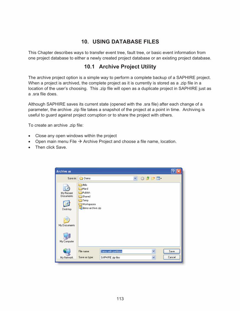
113
10. USING DATABASE FILES
This Chapter describes ways to transfer event tree, fault tree, or basic event information from one project database to either a newly created project database or an existing project database.
10.1 Archive Project Utility
The archive project option is a simple way to perform a complete backup of a SAPHIRE project. When a project is archived, the complete project as it is currently is stored as a .zip file in a location of the user’s choosing. This .zip file will open as a duplicate project in SAPHIRE just as a .sra file does.
Although SAPHIRE saves its current state (opened with the .sra file) after each change of a parameter, the archive .zip file takes a snapshot of the project at a point in time. Archiving is useful to guard against project corruption or to share the project with others.
To create an archive .zip file:
� Close any open windows within the project � Open main menu File � Archive Project and choose a file name, location. � Then click Save.
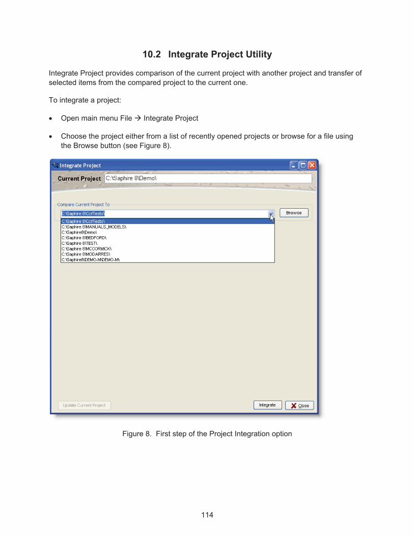
114
10.2 Integrate Project Utility
Integrate Project provides comparison of the current project with another project and transfer of selected items from the compared project to the current one.
To integrate a project:
� Open main menu File � Integrate Project
� Choose the project either from a list of recently opened projects or browse for a file using the Browse button (see Figure 8).
Figure 8. First step of the Project Integration option

115
� Click on the Integrate button to compare the files.
� The report will show the differences between the two projects

116
To transfer items from the compared project to the current project:
� As shown above, place check marks in the boxes next to Basic Events, Event Models, Fault Trees, and Event Trees desired for import into the current project.
� Click on Update Current Project to start the import and a verification window will open.
� After reviewing the items to be added either click on Perform Update to add them to the current project or Cancel to exit.
10.3 The MAR-D Module
MAR-D provides another interface to load or extract data files that define the PRA database. The files are in a "flat-file" or ASCII file format. This is the legacy module for transferring files and is still fully supported in SAPHIRE 8.
Typical uses of MAR-D include:
� Transfer PRA information between data bases
o Extracting MAR-D files from one SAPHIRE project and loading them (via MAR-D) into another SAPHIRE project. (The SAPHIRE project may be a new one or a previously existing project.)

117
� Import other PRA code information
o Formatting the model information from another PRA code to use MAR-D file formats and creating a SAPHIRE project by loading the files via MAR-D.
� Edit PRA files using a text editor
o Extracting MAR-D files from a SAPHIRE project, editing the files to make changes to the model or model descriptions, and loading those files (via MAR-D) back into the SAPHIRE project.
� Archiving PRA files
o Saving the MAR-D files for long term storage in a text format rather than the native binary SAPHIRE format.
10.3.1 MAR-D File Format
The MAR-D file text format and field descriptions are provided in Volume 7 of this NUREG series. Some general MAR-D formatting rules are:
� Use UPPER CASE for event and model names, i.e., CCS, C-CV-A.
� Upper and lower case can be used for descriptive text fields.
� Entries longer than the allowed field length will be truncated.
� Commas are field delimiters in most formats; therefore, commas cannot be used in descriptive text fields.
� Leading or trailing "empty" spaces are allowed.
� An "*" denotes a comment field in most formats; however, " | " denotes a comment field in rule files.
� A single line should not exceed 250 characters in length.
� ^EOS is used to signal the separation of MAR-D input contained in a single file. For example, when fault tree logic for more than one fault tree is contained in a single file, the ^EOS signals that the data for the current fault tree is complete and that another fault tree follows.
� File storage will create a .MARD file extension and a subfolder to the location the .MARD file is stored (see Figure 9).
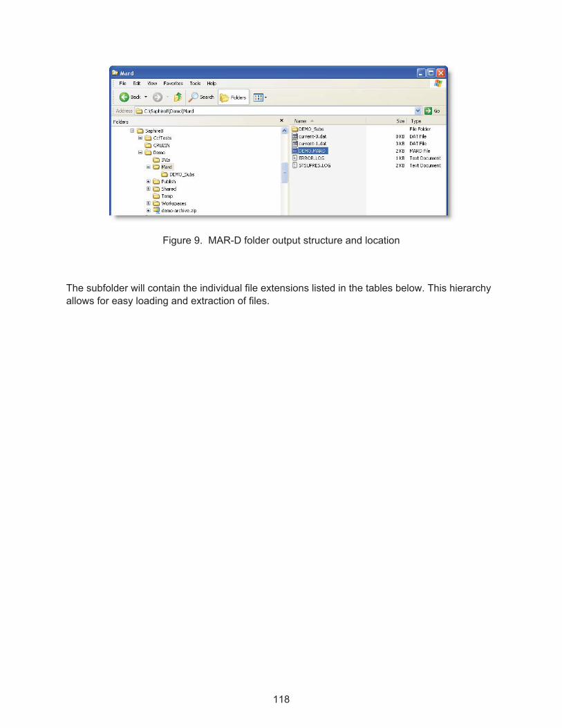
118
Figure 9. MAR-D folder output structure and location
The subfolder will contain the individual file extensions listed in the tables below. This hierarchy allows for easy loading and extraction of files.

119
Key Mar-D File Descriptions and General Guidance for Usage
Project Information
Mar-D File Description Extension General Guidance
Project Names/Description .FAD Optional.
Project Attribute File .FAA Descriptive, contains default mission time
Project Textual Information .FAT Descriptive information only.
Project Recovery Rules .FAY Needed if feature is used.
Project Partition Rules .FAP Needed if feature is used.
Project System Recovery .FAS Needed if feature is used.
Fault Tree Information
Mar-D File Description Extension General Guidance
Fault Tree Name/Description .FTD Load prior to other fault tree/event tree files.
Fault Tree Logic .FTL Contains the logic structure
Fault Tree Text Information .FTT Descriptive information only.
Fault Tree Recovery Rules .FTY Needed if feature is used.

120
Basic Event Information
Mar-D File Description Extension General Guidance
Basic Event Name/Description .BED Load prior to other event information files.
Basic Event Rate Information .BEI Usually needed.
Basic Event Attribute Codes .BEA Needed if feature is used.
Basic Event Transformations .BET Needed if feature is used.
Basic Event Compound .BEC Needed if feature is used.
Basic Event Text .BEN Needed if feature is used.
Event Tree Information
Mar-D File Description Extension General Guidance
Event Tree Name/Description.ETD Load prior to other tree/sequence info.
Event Tree Attributes .ETA Usually needed
Event Tree Graphics .ETG Event tree logic structure
Event Tree Rules .ETR Needed if feature is used.
Event Tree Text Information .ETT Descriptive information only.
Event Tree Recovery Rules .ETY Needed if feature is used.
Event Tree Partition Rules .ETP Needed if feature is used.
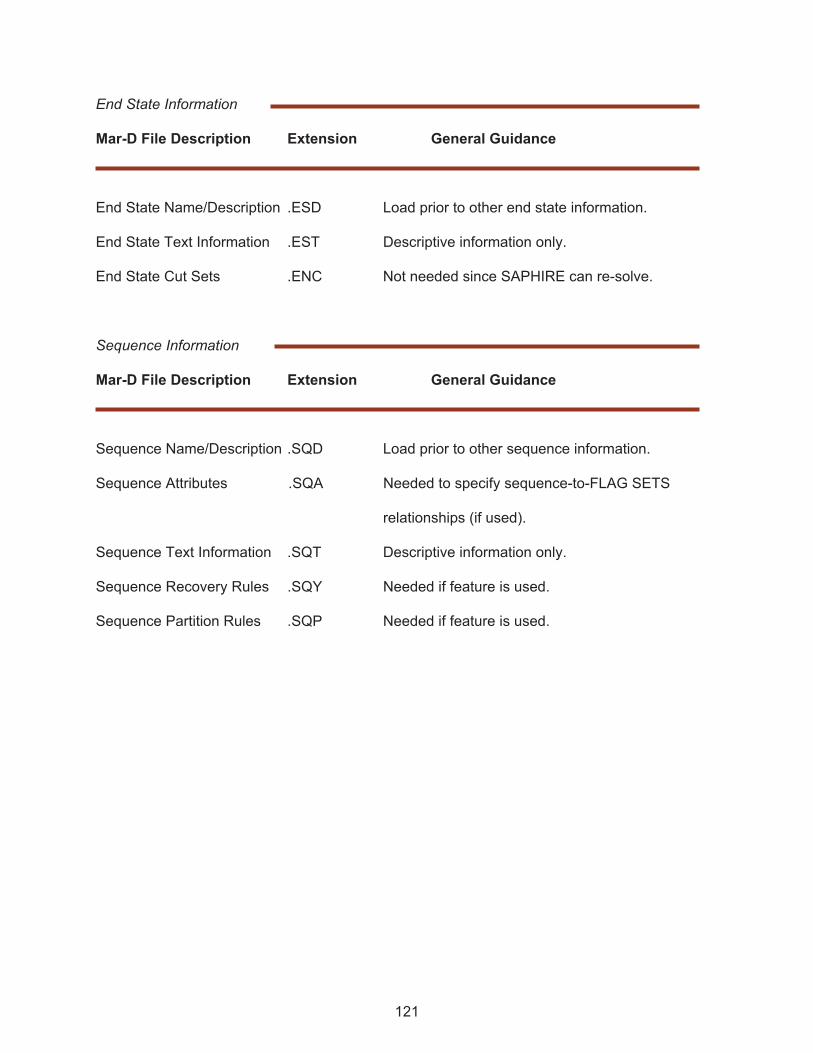
121
End State Information
Mar-D File Description Extension General Guidance
End State Name/Description .ESD Load prior to other end state information.
End State Text Information .EST Descriptive information only.
End State Cut Sets .ENC Not needed since SAPHIRE can re-solve.
Sequence Information
Mar-D File Description Extension General Guidance
Sequence Name/Description .SQD Load prior to other sequence information.
Sequence Attributes .SQA Needed to specify sequence-to-FLAG SETS
relationships (if used).
Sequence Text Information .SQT Descriptive information only.
Sequence Recovery Rules .SQY Needed if feature is used.
Sequence Partition Rules .SQP Needed if feature is used.

122
10.3.2 MAR-D Load and Extract Menus
The MAR-D menus are provided via the main menu File � Load/ Extract option.
The “Load” tab allows for loading MAR-D files.
� Click on “Open” to browse for files available to load. The compatible files must have the designated extension (.MARD for the new format) and a subfolder such as with the designated file extensions listed above (e.g. .BEA, etc...). The format must conform to MAR-D specification.
� Expand the item list as necessary and place a check in the checkboxes of the available information and the correct file extensions located in the subfolder are automatically selected for loading.
� Click “Process” to load the files.

123
The “Extract” tab allows for saving MAR-D files from the database to a storage drive.
� To extract information from SAPHIRE, select the Extract tab then select what information is to be extracted by checking the checkboxes.
� Click “Save As” and select a filename and location to save the files.
o The default name is usually the project name and the .MARD extension.
o The default location is the project \Mard subdirectory.
� Click “Process” and the files will be saved with a root .MARD filename and a subfolder named (filename)_Subs will be created with all of the individual file extensions, as described above.
� When sharing the MAR-D information, it is necessary to share both the .MARD file and the subfolder with the individual file extensions.


125
11. MODEL TYPES
This section describes the use of SAPHIRE 8 Model Types.
11.1 Describing Model Types
SAPHIRE 8 can set up any number of model type analyses with the default being Random (Level 1, internal events PRA). Examples of other models types include:
� SEISMIC (external events related to earthquakes or other ground disturbances). � FIRE (external events related to fires). � FLOOD (external events related to flooding). � ASP_INIT_EVENT (Accident sequence precursor related to initiating event assessments). � ASP_CONDITION (Accident sequence precursor related to condition assessments).
Note that Model Types have been designed to replace older (previously to SAPHIRE 8) “analysis types.”
To add or modify an existing model type select Project � Model Types to open the form below.
The default Analysis Type is set to RANDOM and it will be the only model type present when starting a new project. The project must always have at least one model type. To add a model type, select Add Model Type and click Go. This step will display the dialog shown in Figure 10.

126
Figure 10. Editing a model type
Enter a name, ID and description for the model type then select a unique primary/stacked color combination by using the slider arrow over the color bar and click OK.
The newly created model type will now be available when editing basic events and in analysis options discussed later in this manual. Events can be assigned to multiple model types or just one. If an event uses a model type, the event is prevented from deletion.
11.2 Using Model Types
Within an SAPHIRE project, individual basic events may be tied to a model type. A basic event will be able to “cloned” so that one failure model is used during a model type while a different failure model (including failure parameters) is used in a different model type. SAPHIRE will automatically make these cloned events in the database at the time the model type information is assigned to the basic event. The naming convention for these events will use the nominal basic event name (up to 20 characters) and then append it with a user-defined delimiter (for example, either “-“ or “_”) and then the model type ID (up to 3 characters).
When editing a basic event, the dialog will have a “Applicability” option. The model type applicability attributes will define the event’s specific instance to be used for each model type. The available model types will be user defined (as discussed in Section 11.1).

127
Within a SAPHIRE project, event trees will be associated with one or more model type. These assignments will be made via the applicability modification for initiator basic events. Note that an initiating event may be assigned to two model types. For example, a seismic event tree initiating event will be assigned to the seismic model type, thereby allowing seismic events to appear in its cut sets. However, one may wish to assign the seismic event tree initiating event to the “full power internal events” model since components may still fail due to “random” failures in addition to the seismic-induced failures. Conversely, if a basic event is applicable only to the seismic model type, it should not appear in the cut sets related to non-seismic initiating events. Thus, any event trees that have initiators that do not have the seismic applicability set will not generate seismic-related basic events.
When solving for cut sets, the Model Type(s) to be solved should be indicated on the solve screen (upper right) as indicated in Figure 11.

128
Figure 11. Solve cut sets screen to indicate model type
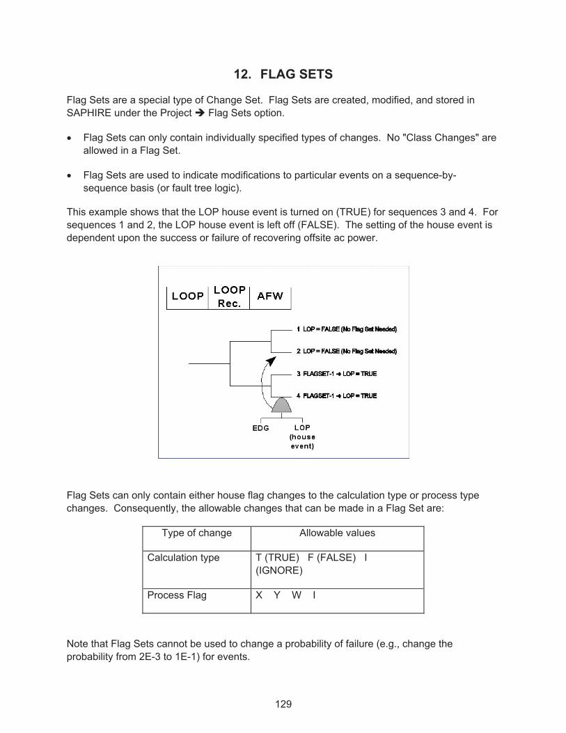
129
12. FLAG SETS
Flag Sets are a special type of Change Set. Flag Sets are created, modified, and stored in SAPHIRE under the Project � Flag Sets option.
� Flag Sets can only contain individually specified types of changes. No "Class Changes" are allowed in a Flag Set.
� Flag Sets are used to indicate modifications to particular events on a sequence-by-sequence basis (or fault tree logic).
This example shows that the LOP house event is turned on (TRUE) for sequences 3 and 4. For sequences 1 and 2, the LOP house event is left off (FALSE). The setting of the house event is dependent upon the success or failure of recovering offsite ac power.
Flag Sets can only contain either house flag changes to the calculation type or process type changes. Consequently, the allowable changes that can be made in a Flag Set are:
Type of change Allowable values
Calculation type T (TRUE) F (FALSE) I (IGNORE)
Process Flag X Y W I
Note that Flag Sets cannot be used to change a probability of failure (e.g., change the probability from 2E-3 to 1E-1) for events.

130
12.1 Making a Flag Set
Enter the Project � Flag Sets option to open the Flag Set List window.
To create a Flag Set, highlight Add Flag Set in the pull down menu, click Go and enter the Flag Set name and description. Once Flag Sets are created, they can be modified or deleted through the Flag Set List window in the same manner.
With the Flag Set Editor now active, drag and drop the desired Basic Events into the Flag Set and change the desired Set Values.
As shown in the figure, a Flag Set is being created in this example. C-CV-A has had its Set Value changed to House = 1 (T). Values are changed simply by clicking on the New Value and choosing from a drop down menu. In this illustration, DG-B is currently being dragged to the Flag Set Editor. Note the cursor shape changes from an arrow to a page with arrow when a drag and drop operation is being performed.
To remove an event from the Flag Set, highlight the event and click on the button Remove Event.

131
12.2 Using a Flag Set
There are two ways to use a Flag Set after creation. One is to assign Flag Sets directly to sequences (highlight a sequence, right click, and select Properties). The other way to use flag sets is to use a Dynamic Flag Set assigned to sequences based on Event Tree rules.
“Dynamic” Flag Sets are a special type of Flag Set that is assigned to sequences by the use of event tree rules. In other words, they are rule-based flag sets. A Dynamic Flag Set is assigned to a sequence if the sequence meets the search criteria contained in the rule.
Advantages of “Dynamic” Flag Sets are:
� Given a change in the event tree logic, the Dynamic Flag Set will automatically assign itself to the sequence that meets the search criteria contained in the rule.
� For example, if the rule assigns a Flag Set to sequence LOOP 05 and the event tree logic changes to make this sequence LOOP 08, then the Flag Set will automatically be assigned to LOOP 08 once the event tree sequences are regenerated.
� Dynamic Flag Sets are created and assigned to the sequences every time the event tree sequence logic is generated.


133
13. THE SAPHIRE RULES EDITORS
The following rules editors are available in SAPHIRE:
� Project Level
o End State Partition o Fault Tree Post Processing o Event Tree Post Processing
� Event Tree Level
o Linkage o Cut Set Post Processing o Partition
� Fault Tree Level
o Cut Set Post Processing
The default configuration for the rules editor is shown below. The editing pane is numbered and when script is entered, the editor automatically displays comments in blue and functions are bolded. A function pane to the right includes functions used in the particular editor’s context.

134
The rules editor toolbar contains the following items:
Save Compile
Undo or Redo action Find, Find Next, and Find Previous
Replace Comment/Un-Comment highlighted block
The rules editor menu bar includes the following options:
� File – The file drop down menu allows the user to compile, import or export text, and save or both save and exit the rule editor. A check of the script status is performed on an exit of the rule editor. If there is a problem found (i.e. script is not compiled or has errors in the compile) the user is prompted to optionally fix the problem without exiting the editor.
� Edit – The edit drop down menu allows the user to undo, redo, cut, copy, paste insert indents or spaces, comment or uncomment any portions of the existing rules,
� Search – The search drop down menu allows the user the ability to search the rules, find the next or previous, or replaces character strings.
� View – The view drop down menu is used in concurrence with Options � Show Item Lists and will show or hide items in the list pane opened to the left of the editing pane.
� Options – The options drop down menu controls what panes are visible (Show Function List and Show Item List), what is displayed in the list pane (Header and Description), and can save the current configuration as the default configuration for the rules editors in the project.
The following image shows the rules editor including the list pane.
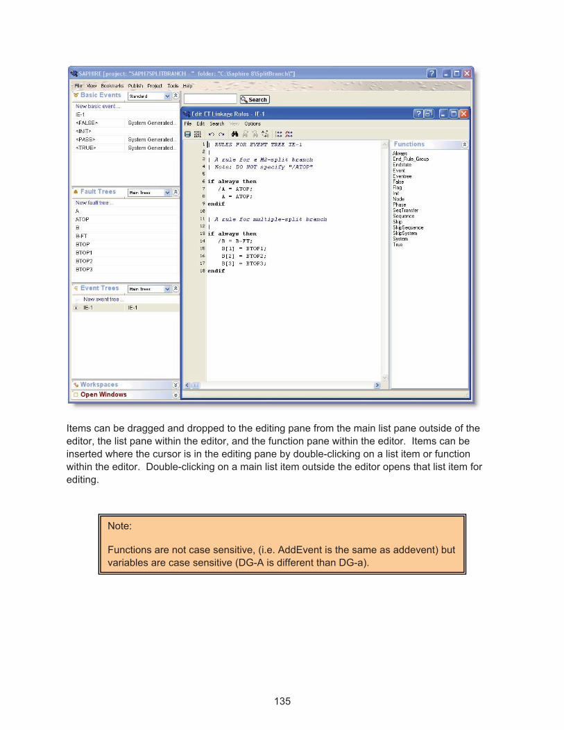
135
Items can be dragged and dropped to the editing pane from the main list pane outside of the editor, the list pane within the editor, and the function pane within the editor. Items can be inserted where the cursor is in the editing pane by double-clicking on a list item or function within the editor. Double-clicking on a main list item outside the editor opens that list item for editing.
Note:
Functions are not case sensitive, (i.e. AddEvent is the same as addevent) but variables are case sensitive (DG-A is different than DG-a).

136
13.1 LINKING EVENT TREES
This section introduces the edit linkage rules editor used to link event tree sequences. This rule editor allows for the creation of rules that affect sequence generation. Typically, these rules are used to replace the default fault trees with either a substituted fault tree or a "split-fraction" event based on logical conditions that are specified in the rules.
"Linking" event trees is the process of generating sequence logic using the event tree graphical files.
13.1.1 Menus and Options for Linking Event Tree Sequences
Linking is performed automatically when the event tree is saved from the editor or it can be initiated by right clicking on the event tree in the list window and selecting “Link”.
If there are no “link rules” defined for the event tree, SAPHIRE simply constructs the sequence logic based upon the top events identified on the event tree graphic (as shown above). But, event tree linking rules allow us to control the logic for each sequence based upon predefined rules.
Rules editors provided for event trees in SAPHIRE are accessible by right clicking on the Event Tree name in the Event Tree list window. Select Edit Linkage Rules to open the linkage rules editor. The cut set and partition editors are not discussed in this section. The linkage rules editor allows rules to be written that are used when sequence logic is generated.
These rules allow the user to replace one or more top events with a substituted top event based on the logical conditions dictated by the rule.
These rules also allow the user to assign flag sets to sequences based on the logical conditions dictated by the rule.

137
13.1.2 Link Event Trees Rules Nomenclature and Structure
This rule editor is used when the “Link Trees” operation is performed when the event tree is saved from the event tree editor and the sequence logic is being created. If linking rules exist, the rule searches the event tree logic for the search criteria specified in the rule and replaces the default top event (just in the sequence logic, not on the graphic) by a new top event.
Symbols
| Denotes a comment line ~ Operator for "not present"
* Logical AND operator + Logical OR operator
/ Complement ( ) For grouping terms
; End of replacement line
?? Wildcard of length in string of “?”, (in this case 2)
Search Criteria
Examples are for an event tree with initiating event IE and top events A, B, and C.
init(IE) Initiating event with the name IE
A Failure of top event or fault tree A
/A Success of top event or fault tree A (/ indicates complement)
~A Failure of A not present (~ indicates something is not present)
~(/A + A) Success of A and failure of A not present (can be used to test for a "pass" condition)
A * B Failure of A and of B occurs
(A + B) * C Failure of A or B occurs and failure of C occurs always. This pre-defined macro name means the criteria is always met.
To help in understanding the rules, we provide several examples.
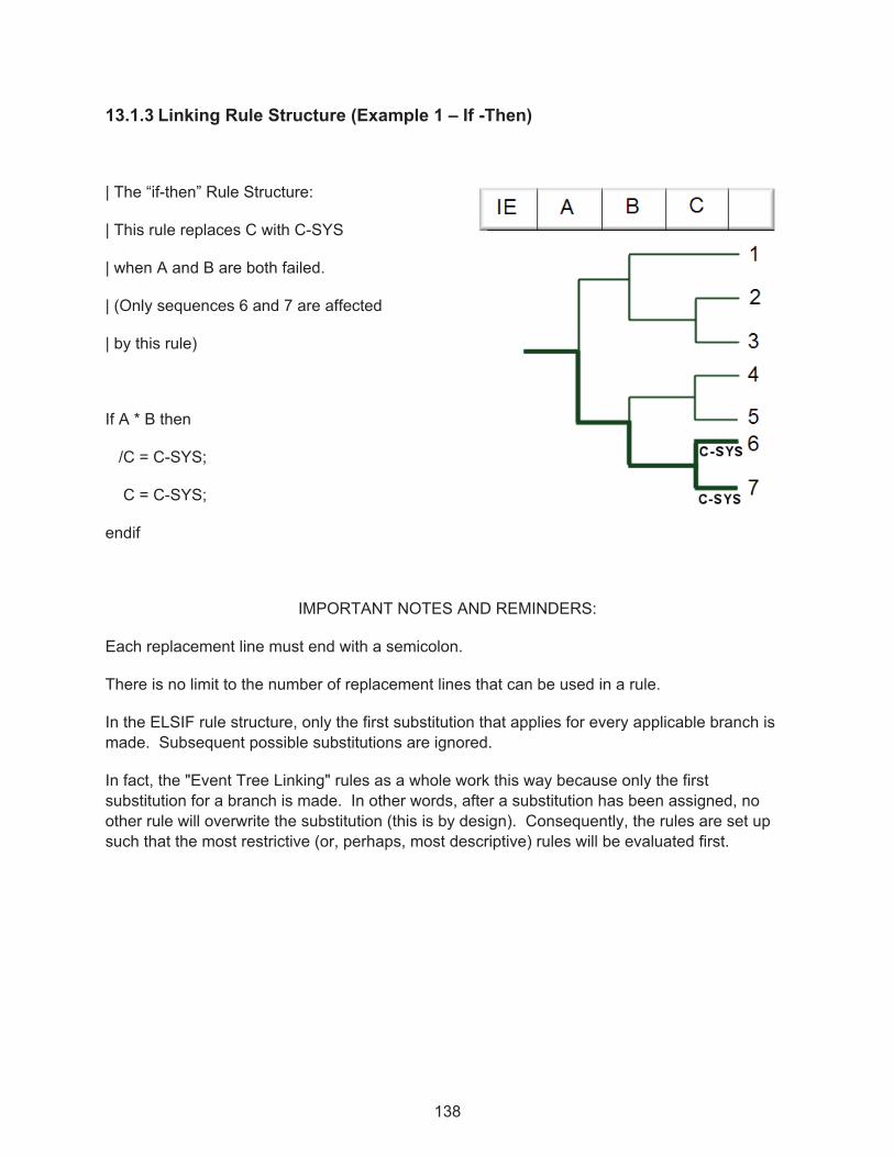
138
13.1.3 Linking Rule Structure (Example 1 – If -Then)
| The “if-then” Rule Structure:
| This rule replaces C with C-SYS
| when A and B are both failed.
| (Only sequences 6 and 7 are affected
| by this rule)
If A * B then
/C = C-SYS;
C = C-SYS;
endif
IMPORTANT NOTES AND REMINDERS:
Each replacement line must end with a semicolon.
There is no limit to the number of replacement lines that can be used in a rule.
In the ELSIF rule structure, only the first substitution that applies for every applicable branch is made. Subsequent possible substitutions are ignored.
In fact, the "Event Tree Linking" rules as a whole work this way because only the first substitution for a branch is made. In other words, after a substitution has been assigned, no other rule will overwrite the substitution (this is by design). Consequently, the rules are set up such that the most restrictive (or, perhaps, most descriptive) rules will be evaluated first.

139
13.1.4 Linking Rule Structure (Example 2 – if-then-elsif)
| The "if-then-elsif" Structure:
| This rule replaces C with C-AB if A and B are
| failed, and replaces C with C-B if only B is failed.
if A * B then
/C = C-AB;
C = C-AB;
elsif B then
/C = C-B;
C = C-B;
endif
13.1.5 Linking Rule Structure (Example 3 – if-then-elsif-else)
| The "if-then-elsif-else" Structure:
| This rule:
| Replaces C with C-NA when A is successful
| Replaces C with C-NB if B is successful
| Replaces C with C-XX in any other case
if /A then
/C = C-NA;
C = C-NA;
elsif /B then
/C = C-NB;
C = C-NB;
else
/C = C-XX;
C = C-XX;
endif

140
13.1.6 Linking Rule Structure (Example 4 – always)
| The "if-always" Rule Structure:
| This rule replaces every occurrence
| of C with C-SYS.
|
| (Sequences 2 through 7 are
| affected)
if always then
/C = C-SYS;
C = C-SYS;
endif
13.1.7 Linking Rule Structure (Example 5 – If –Then with wildcards)
| The "if-then" Rule Structure using
| wildcards:
| This rule replaces C with C-SYS
| when the initiating event occurs.
| (Sequences 3, 5 and 7 are affected)
if “??” then
C = C-SYS;
endif
| The “??” finds the initiating event,
| but will key on any top of exactly
| two characters in length.

141
13.2 Linking Rules "Macro" Structures
Macros can streamline the development of complex rules. A macro is simply a statement to define a search criterion and assign a name to that search criterion. Examples are provided below.
13.2.1 Linking Rule Structure (Example 6 – macros)
| Define a macro named AB-FAIL
AB-FAIL = A * B;
|
| Use the macro in a rule
if AB-FAIL then
/C = C-SYS;
C = C-SYS;
endif
� If creating a rule where the events in the macro do not occur, use the ~ (i.e., not present) symbol.
� If looking for success events, do not "complement" the macro. Instead, complement the events of interest. For example, if looking for success of A, use A-MACRO = /A;. Do not try A-MACRO = A; if /A-MACRO then…

142
13.2.2 Linking Rule Structure (Example 7 – not found ~)
| Using ~macro as the search criteria:
| The rule applies when both A and B
| have not failed.
| Define a macro named AB-FAIL
AB-FAIL = A * B;
| Use the macro in a rule
if ~AB-FAIL then
/C = C-SYS;
C = C-SYS;
endif
13.2.3 Linking Rule Structure (Example 8 – ignoring sequences via the SKIP keyword)
| The "Skip" Structure:
| This rule provides the ability to “skip” sequences
| in the event tree logic.
|
| This rule “skips” C given the failure of B. (The
| sequences that meet the rule logic are
| not generated when the rule is applied, however,
| the sequence| names (numbers) are left
| unchanged. Therefore, no sequence
| cut sets can be generated for skipped sequences.)
|
if B then
/C = Skip(C);
C = Skip(C);
endif

143
For this rule only sequences 1, 4, and 5 will be generated, since all sequences where B fails have been skipped.
13.3 Changing Transfers Trees using Link Rules
The Link Rules may also be used to control the transfer process from one event tree to a sub tree. This ability brings in the use of a new keyword, eventree(). See the example below.
13.3.1 Linking Rule Structure (Example 9 – changing the transfer tree via EVENTREE)
| This rule is for a transfer tree named SHARED. The SHARED event tree is transferred to
| by two different event trees, each having a unique initiating event. The first event tree has
| initiating event IE-A, and after it transfers to SHARED, it should transfer to an event tree
| named A-PRT. The second event tree has initiating event IE-B, and after it transfers
| to SHARED, it should transfer to an event tree named B-PRT.
| The transfer name on the SHARED event tree graphic is A-PRT. This rule
| changes the specified transfer event tree to B-PRT when the initiator is IE-B.
if init(IE-B) then
eventree(A-PRT) = eventree(B-PRT);
endif

144
13.4 Event Tree Linking Rule Keywords and Nomenclature
Each of the “rules” in SAPHIRE (linking, recovery, and partition) has their own nomenclature. The table below lists the keywords available for linking rules.
Keyword or symbol Definition Example Usage
if then
Keyword that indicates a search criterion is being specified.
if "search criteria" then
perform some action on the sequence;
endif
Endif
Keyword that indicates the end of a particular rule.
if "search criteria" then
perform some action on the sequence;
endif
Else
Keyword that specifies some action to be taken if all the search criteria are not met. The else should be the last condition in the event tree linking rule.
if "search criteria" then
perform some action on the sequence;
else
perform some other action on the sequence if search criteria not met;
endif
Elsif
Keyword that specifies an alternative search criteria. Any number of elsifs can be used within an event tree linking rule.
if "search criteria" then
perform some action on the sequence;
elsif "2nd search criteria" then
perform some other action on the sequence;
elsif "3rd search criteria" then
perform some other action on the sequence;
endif
always
Keyword that indicates every fault tree top event satisfies the search criteria.
if always then
perform some action on the sequence;
endif
init( )
Keyword used in the search criteria to indicate that the sequence logic has a particular initiating event.
if init(INITIATOR-NAME) * "other search criteria if needed" then
perform some action on the sequence;
endif

145
Keyword or symbol Definition Example Usage
End_Rule_Group Provides a break from one rule group to the next rule group in layered rules.
~
Symbol used in the search criteria to indicate that a particular top event will not be in the sequence logic that is being tested.
if (~SEARCH-CRITERIA) * "other search criteria if needed" then
...
The search criteria will be satisfied for all sequences that do not contain SEARCH-CRITERIA (and also contains the optional "other search criteria"). SEARCH-CRITERIA may be an initiating event, top event, or macro.
/
Symbol used to represent a complemented event (i.e., the success of a fault tree).
if (/TOP EVENT) * "other search criteria" then
The search criteria will be satisfied for all sequences that contain the complement of TOP EVENT (and also contains the optional "other search criteria").
|
Symbol used to represent a comment contained in the rules. Everything on a line to the right of this symbol will be ignored by the rule compiler.
| Place comments here!
| Note that blank lines are also permissible!
;
Symbol to indicate the end of a macro line or a line that modifies the sequence logic being evaluated.
| usage for a macro command
MACRO-NAME = "search criteria" ;
| usage for a sequence modification line
FT = FT-1;
*
Symbol to indicate the logical AND command.
if SEARCH-CRITERIA1 * SEARCH-CRITERIA2 then
The search criteria will be satisfied for all top events that match SEARCH-CRITERIA1 and SEARCH-CRITERIA2. The SEARCH-CRITERIA# may be an initiating event, macro, or top event.

146
Keyword or symbol Definition Example Usage
+
Symbol to indicate the logical OR command.
if SEARCH-CRITERIA1 + SEARCH-CRITERIA2 then
The search criteria will be satisfied for all top events that match either SEARCH-CRITERIA1 or SEARCH-CRITERIA2. The SEARCH-CRITERIA# may be an initiating event, macro, or top event.
( )
Symbols to indicate a specific grouping of items.
if (A + B) * (C + D) then
The search criteria above would return all top events that contain:
[A * C], [A * D], [B * C], or [B * D].
=
Keyword to indicate the substitution of one event tree top (i.e., fault tree) for another event.
if "search criteria" then
ET-FT = ET-FT1;
endif
endstate Keyword to assign a sequence (based upon sequence logic) to a particular end state.
If “search criteria” then
eventree(ET-NAME) = endstate(ES-NAME);
endif
eventree( )
Keyword to indicate a change in the sequence transfer name.
if "search criteria" then
eventree(ORIG-TRAN) = eventree(NEW-TRAN);
endif
Skip( )
Keyword to indicate that a sequence meeting the search criteria will be “skipped” (i.e., not generated and will not show up in the database).
if "search criteria" then
ET-FT = Skip(ET-FT);
endif
SkipSequence
SkipSystem
Keywords with the same function as Skip( ), however it provides further delineation between sequence and system with the use of categories.
[ ]
Keyword to indicate the number of the event tree branch for multiple-split branch points. The first branch under the top branch is designated as 1. The second is designated as 2, etc.
if "search criteria" then
/ET-FT = NEW-TREE-NAME1;
ET-FT[1] = NEW-TREE-NAME2;
ET-FT[2] = NEW-TREE-NAME3;
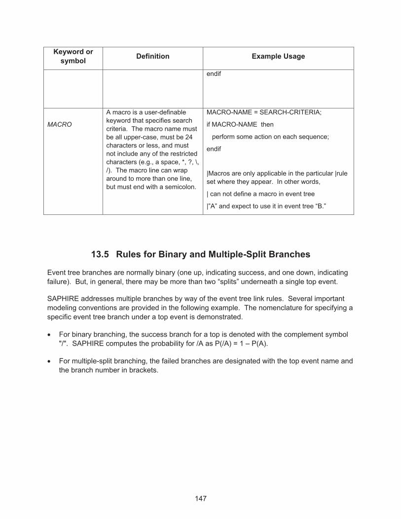
147
Keyword or symbol Definition Example Usage
endif
MACRO
A macro is a user-definable keyword that specifies search criteria. The macro name must be all upper-case, must be 24 characters or less, and must not include any of the restricted characters (e.g., a space, *, ?, \, /). The macro line can wrap around to more than one line, but must end with a semicolon.
MACRO-NAME = SEARCH-CRITERIA;
if MACRO-NAME then
perform some action on each sequence;
endif
|Macros are only applicable in the particular |rule set where they appear. In other words,
| can not define a macro in event tree
|”A” and expect to use it in event tree “B.”
13.5 Rules for Binary and Multiple-Split Branches
Event tree branches are normally binary (one up, indicating success, and one down, indicating failure). But, in general, there may be more than two “splits” underneath a single top event.
SAPHIRE addresses multiple branches by way of the event tree link rules. Several important modeling conventions are provided in the following example. The nomenclature for specifying a specific event tree branch under a top event is demonstrated.
� For binary branching, the success branch for a top is denoted with the complement symbol "/". SAPHIRE computes the probability for /A as P(/A) = 1 – P(A).
� For multiple-split branching, the failed branches are designated with the top event name and the branch number in brackets.

148
The success branch (the uppermost one) is assigned index [0], but is indicated by using the “/” nomenclature (see above). Then, the next branch (below the success branch) is assigned index [1], the next branch index [2], etc.
| RULES FOR EVENT TREE IE-1
|
| A rule for a 2-split branch
| Note: DO NOT specify “/ATOP”
if always then
/A = ATOP;
A = ATOP;
endif
| A rule for multiple-split branch
|
if always then
/B = B-FT;
B[1] = BTOP1;
B[2] = BTOP2;
B[3] = BTOP3;
endif
If a logic report is printed to the screen during the link process (Right Click on Event Tree IE-1 in list window select Link, and then check the “Create Report” box before clicking on OK) it will look like:

149
For multiple-split branches, it may be desirable to construct a fault tree with the name that corresponds to the substituted success branch name (in our case, B-FT).
The “success branch” fault tree would consist of the failed systems, BTOP1, BTOP2, and BTOP3 "ORed" together. Remember that SAPHIRE will automatically complement the fault tree when it solves the success branch (i.e., the uppermost branch).
To include a complemented event in event tree cut sets, specify the Y Process Flag (in the Modify � Basic Events option) for the applicable top event. In this example, set the Y Process Flag for ATOP and B-FT.
Then, to use the correct probability for this “success branch” fault tree:
� Set the B-FT event to a calculation type of “S” in order to tell SAPHIRE to use the fault tree cut sets for the event probability.
� Solve the fault tree (B-FT) prior to the sequence analysis.


151
14. POST-PROCESSING RULES
This section presents the post-processing rules editors. These editors allow for the creation of rules that affect existing cut sets in a “post-processing” fashion. The rule-based editors are available for both fault tree and sequence cut sets.
14.1 Post-Processing Rules Editor Introduction
Project level post-processing rules applied to all event trees and fault trees are accessed from the main screen top menu bar Project � Edit Rules � ET (Post Processing) or FT (Post Processing). Rules applied to individual event trees and fault trees are accessed by right clicking on the appropriate tree and selecting Edit Cut Set Rules. The SAPHIRE post-processing rules are "free-form" logic rules that allow for the alteration or deletion of fault tree or sequence cut sets.
The Post-processing Rules can be used for probabilistic risk assessment techniques such as:
� The automated inclusion of sequence recovery events � The inclusion of common-cause failure cut sets � The elimination of mutually-exclusive events (e.g., impossible combinations of events).
The rules follow a format similar to the structure that is found in traditional programming languages (e.g., BASIC or PASCAL). As such, the ability exists to define "macros" and "if...then" type of structures.
The post-processing rules may be developed for a particular fault tree; all fault trees, a particular sequence, a single event tree, or all sequences.
Item Menu Path Name of rule(s)
Specific fault tree Fault Tree � Edit Cut Set Rules “Fault Tree” Rule Level
All fault trees Project � Edit Rules � FT “Project” Rule Level
Single event tree Event Tree � Edit Cut Set Rules “Event Tree” Rule Level
All sequences Project � Edit Rules � ET “Project” Rule Level
The rules are entered in a free-form text editor within SAPHIRE. Note: The rules can be exported and loaded through MAR-D. Use of the post-processing rules could result in non-minimal cut sets. Thus, the typical steps in performing an analysis using the post-processing rules are:
� Finalize logic models and data changes by saving any modified trees � Solve fault tree or sequence cut sets

152
� Apply post-processing rules to applicable fault trees or sequences � Perform a Cut Set Update to fault tree or sequence cut sets � Perform Uncertainty analysis � Display or report results
14.2 Post-processing Rules Nomenclature and Structure
These examples apply to all the post-processing rules editors. This rule editor searches existing fault tree or sequence cut sets for cut sets matching the search criteria defined in the rule. The rule is used to modify the cut sets matching the search criteria.
Symbols
| Denotes a comment line ~ Operator for "not present"
* Logical AND operator + Logical OR operator
/ Complement ( ) Parentheses
Search Criteria Meaning of the Search Criteria
X Basic event X appears in the cut set
~X Basic event X does not occur in the cut set
/X Success of basic event X appears in the cut set
X * Y Both basic events X and Y appear in the cut set
X + Y Either basic event X or Y appear in the cut set
X*(Y + Z) Either X and Y or X and Z appear in cut set in the cut set
~X*Y Basic event Y does appear and basic event X does not appear
always This pre-defined macro-name means the criteria is always met.
system(ECS) Fault tree top event with name ECS
To help in understanding the post-processing, several examples are provided.

153
14.2.1 Post-processing Rule Structure (Example 1 – if-then)
| The "if-then" Rule Structure:
| This rule adds a recovery action BUSREC when electric bus B or C is failed
if EL-BUS-B + EL-BUS-C then
recovery = BUSREC; |This keyword line must end with a semicolon.
endif
14.2.2 Post-processing Rule Structure (Example 2 – if-then-elsif)
| The "if-then-elsif" Structure:
| This rule deletes the cut set if both diesel generators are out for maintenance.
| If the two DGs fail randomly, add a common cause event.
if (DG-1-MAINT * DG-2-MAINT) then
DeleteRoot;
elsif (DG-1-RAND * DG-2-RAND) then
| Copy the original cut set, remove the two failure events, then add CC
CopyRoot;
DeleteEvent = DG-1-RAND;
DeleteEvent = DG-2-RAND;
AddEvent = DG-CCF-1AND2;
Endif

154
14.2.3 Post-processing Rule Structure (Example 3 – appending recovery actions)
The example below shows how the post-processing rules could be used to include recovery actions on specific cut sets.
| The rule attaches the recovery action NRAC-12HR to every cut set for a particular sequence.
| This rule would probably be typed into the event tree sequence rule editor for the sequence of
| interest. A rule to apply NRAC-12HR recovery event to all cut sets in the sequence.
if always then
recovery = NRAC-12HR;
endif
14.2.4 Post-processing Rule Structure (Example 4 – mutually exclusive event removal)
The example below shows how the rules could be used to completely remove a particular cut set from the cut set list. There may be instances where a cut set should be removed because the combination of basic events should not occur (e.g., two diesel generators out for maintenance at the same time).
| This rule could be placed in either (or both) the fault tree project rules or the event tree project
| rules. Define a macro to get those cut sets that have combinations of two motor
| driven pumps out for maintenance.
PUMPS-IN-MAINT = MDP-A-MAINT * MDP-B-MAINT;
| Search for the maintenance events and then delete cut set.
if PUMPS-IN-MAINT then
| Delete the cut set
DeleteRoot;
endif

155
14.2.5 Post-processing Rule Structure (Example 5 – including common-cause failure events)
The example below shows how the rules could be used to add common-cause events to the cut sets. The usefulness of the Post-processing Rules for common-cause failure modeling is limited by the fact that the cut sets containing the independent random failures must exist for the search criteria to work.
If a probability truncation is specified when generating fault tree or sequence cut sets, the independent failure cut sets may be truncated.
| The search criterion identifies the failure combination of two auxiliary feedwater pumps.
| If these two basic events are found in a cut set then a new cut set will be created that
| replaces the independent failures of the two pumps with a single common-cause basic event.
| This rule could be in either (or both) the fault tree project rules or the event tree project rules.
| Define macro to pick up cut sets that have combinations of AFW-PUMP-A and AFW-PUMP-B.
CCF-AFW-PUMPS = AFW-PUMP-A * AFW-PUMP-B;
| Search for the AFW pump basic events and make a new cut set with the CCF event.
if CCF-AFW-PUMPS then
| First make a copy of the original cut set
CopyRoot;
| Now remove the two independent failure events
DeleteEvent = AFW-PUMP-A;
DeleteEvent = AFW-PUMP-B;
| Now add the CCF event
AddEvent = AFW-PUMP-CCF;
endif
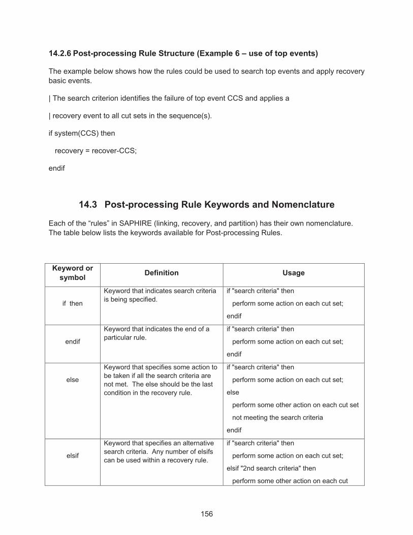
156
14.2.6 Post-processing Rule Structure (Example 6 – use of top events)
The example below shows how the rules could be used to search top events and apply recovery basic events.
| The search criterion identifies the failure of top event CCS and applies a
| recovery event to all cut sets in the sequence(s).
if system(CCS) then
recovery = recover-CCS;
endif
14.3 Post-processing Rule Keywords and Nomenclature
Each of the “rules” in SAPHIRE (linking, recovery, and partition) has their own nomenclature. The table below lists the keywords available for Post-processing Rules.
Keyword or symbol Definition Usage
if then
Keyword that indicates search criteria is being specified.
if "search criteria" then
perform some action on each cut set;
endif
endif
Keyword that indicates the end of a particular rule.
if "search criteria" then
perform some action on each cut set;
endif
else
Keyword that specifies some action to be taken if all the search criteria are not met. The else should be the last condition in the recovery rule.
if "search criteria" then
perform some action on each cut set;
else
perform some other action on each cut set
not meeting the search criteria
endif
elsif
Keyword that specifies an alternative search criteria. Any number of elsifs can be used within a recovery rule.
if "search criteria" then
perform some action on each cut set;
elsif "2nd search criteria" then
perform some other action on each cut

157
Keyword or symbol Definition Usage
set;
elsif "3rd search criteria" then
perform some other action on each cut set;
endif
always
Keyword that indicates that every cut set that is being evaluated satisfies the search criteria.
if always then
perform some action on each cut set;
endif
init( )
Keyword used in the search criteria to indicate that a sequence cut set has a particular initiating event.
if init(INITIATOR-NAME) * "other search criteria if needed" then
perform some action on each cut set;
endif
~
Symbol used in the search criteria to indicate that a particular event will not be in the cut set that is being evaluated.
if (~SEARCH-CRITERIA) * "other search criteria if needed" then
...
The search criteria will be satisfied for all cut sets that do not contain SEARCH-CRITERIA (and also contains the optional "other search criteria"). SEARCH-CRITERIA may be an initiating event, basic event, macro, or logic expression.
/
Symbol used to represent a complemented event (i.e., the success of a failure basic event).
if (/BASIC-EVENT) * "other search criteria" then
The search criteria will be satisfied for all cut sets that contain the complement of BASIC-EVENT (and also contains the optional "other search criteria").
|
Symbol used to represent a comment contained in the rules. Everything on a line to the right of this symbol will be ignored by the rule compiler.
| Place comments here!
| Note that blank lines are also permissible!
;
Symbol to indicate the end of a macro line or a line that modifies the cut set being evaluated.
| usage for a macro command
MACRO-NAME = "search criteria" ;
| usage for a cut set modification line
recovery = RECOVERY-EVENT ;

158
Keyword or symbol Definition Usage
*
Symbol to indicate the logical AND command.
if SEARCH-CRITERIA1 * SEARCH-CRITERIA2 then
The search criteria will be satisfied for all cut sets that match SEARCH-CRITERIA1 and SEARCH-CRITERIA2. The SEARCH-CRITERIA# may be an initiating event, basic event, macro, or logic expression.
+
Symbol to indicate the logical OR command.
if SEARCH-CRITERIA1 + SEARCH-CRITERIA2 then
The search criteria will be satisfied for all cut sets that match either SEARCH-CRITERIA1 or SEARCH-CRITERIA2. The SEARCH-CRITERIA# may be an initiating event, basic event, macro, or logic expression.
( )
Symbols to indicate a specific grouping of items.
if (A + B) * (C + D) then
The search criteria above would return all cut sets that contain:
[A * C], [A * D], [B * C], or [B * D].
system( ) Keyword used in the search criteria to indicate that a fault tree contributes to the existence of the cut set that is being evaluated.
if system(ECS) then
perform some action on each cut set
endif
Recovery =
Keyword that indicates that a recovery event is going to be added to the cut set being evaluated (SAPHIRE keeps record of all recovery events).
if "search criteria" then
recovery = NAME-OF-RECOVERY;
endif
AddEvent =
Keyword that indicates that an event will be added to the cut set being evaluated.
if "search criteria" then
AddEvent = EVENT-NAME;
endif
DeleteEvent=
Keyword that indicates that an event will be deleted from the cut set being evaluated.
if "search criteria" then
DeleteEvent = EVENT-NAME;
endif
NewCutset;
Keyword that indicates that a new, empty cut set will be added to the list of cut sets. This new cut set then becomes the cut set that is being
if "search criteria" then
NewCutset;
now make additions to the empty cut set...
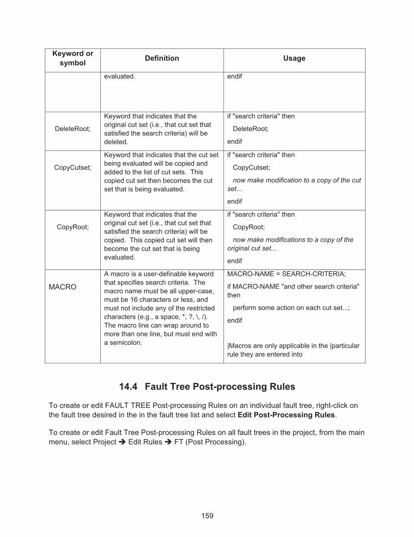
159
Keyword or symbol Definition Usage
evaluated. endif
DeleteRoot;
Keyword that indicates that the original cut set (i.e., that cut set that satisfied the search criteria) will be deleted.
if "search criteria" then
DeleteRoot;
endif
CopyCutset;
Keyword that indicates that the cut set being evaluated will be copied and added to the list of cut sets. This copied cut set then becomes the cut set that is being evaluated.
if "search criteria" then
CopyCutset;
now make modification to a copy of the cut set...
endif
CopyRoot;
Keyword that indicates that the original cut set (i.e., that cut set that satisfied the search criteria) will be copied. This copied cut set will then become the cut set that is being evaluated.
if "search criteria" then
CopyRoot;
now make modifications to a copy of the original cut set...
endif
MACRO
A macro is a user-definable keyword that specifies search criteria. The macro name must be all upper-case, must be 16 characters or less, and must not include any of the restricted characters (e.g., a space, *, ?, \, /). The macro line can wrap around to more than one line, but must end with a semicolon.
MACRO-NAME = SEARCH-CRITERIA;
if MACRO-NAME "and other search criteria" then
perform some action on each cut set...;
endif
|Macros are only applicable in the |particular rule they are entered into
14.4 Fault Tree Post-processing Rules
To create or edit FAULT TREE Post-processing Rules on an individual fault tree, right-click on the fault tree desired in the in the fault tree list and select Edit Post-Processing Rules.
To create or edit Fault Tree Post-processing Rules on all fault trees in the project, from the main menu, select Project � Edit Rules � FT (Post Processing).

160
Fault Tree Post-processing Rules are applied as a default if rules exist for the selected fault tree or group of fault trees. When solving a fault tree or group of fault trees, right click the tree or highlighted group of trees in the Fault Tree list window and select Solve. A check mark should appear in the Apply Post-processing Rules checkbox. Only uncheck the box to omit using the
post-processing rules.
14.5 Event Tree Sequence Post-processing Rules
To create or edit EVENT TREE Post-processing Rules on an individual event tree, right-click on the event tree desired in the event tree list and select Edit Post-processing Rules.
To create or edit Event Tree Post-processing Rules on all event trees in the project, from the main menu, select Project � Edit Rules � ET (Post Processing).
Event Tree Post-processing Rules are applied as a default if rules exist for the selected event tree or group of event trees. When solving an event tree or group of event trees right click the tree or highlighted group of trees in the Event Tree list window and select Solve. A check mark should appear in the Apply Post-processing Rules checkbox. Only uncheck the box to omit the Post-processing rules.

161
15. END STATE ANALYSIS
This section describes the end state analysis features in SAPHIRE. Cut sets derived by analyzing event tree sequences can be grouped into end states by specifying the sequence end state on the event tree or by developing end state partitioning rules. Both approaches are described in this section.
15.1 End State Analysis Approaches
End state analysis is simply the grouping of cut sets generated from event tree sequences in ways that are useful to the analyst. Cut sets grouped by end state can be conveniently displayed and reported, and end state uncertainty analysis can be performed. There are two basic approaches provided in SAPHIRE to group cut sets into end states:
� End state analysis by specifying sequence end states — In this approach, the end state is specified for each event tree sequence in the graphical file.
� End state analysis using partitioning rules — in this approach, user-defined rules are used to assign end states. Features include:
o Application of rules to the entire database project, event trees, and/or sequences. o Cut sets from the same sequence can be grouped into separate end states. o End state names can be creating using a "layering process" that allows character
substitutions.
15.2 End States by Specifying Sequence End States
Two accident end states (SMALL_RELEASE and LARGE_RELEASE) are specified on the LOSP event tree. Note that OK end states are ignored.

162
The end states specified in the "End-State" column automatically become end states in the database. To edit the description of an end state from the main screen, double click on an end state in the End State list. More detailed editing can be accomplished in the Event Tree editor by right clicking on the sequence end state and selecting Edit.
Cross reference an end state by highlighting the end state and using the main menu Tools �Cross References to list the event tree sequences that are grouped into the highlighted end state.
15.3 Gather End State Cut Sets
Steps to gather End State Cut Sets:
� Sequence cut sets must be generated (highlight all Event Trees then right click on the highlighted list and select the Solve option).
� Gather end state cut sets by highlighting all the End States of interest in the End States list panel, right click on the highlighted list and select Gather (if not visible, use the main toolbar View � End States to see the End States list panel).
15.3.1 Options to Gather End States Cut Sets
Performing the gather steps above opens the Solve Cut Sets form (Figure 12).
Figure 12. Solving end state cut sets dialog

163
15.3.2 Gather Cut Sets
This option gathers existing cut sets (generated from the event tree sequences). The end state frequency is quantified using the minimal cut set upper bound approximation. (Non-minimal cut sets are eliminated within each end state.)
15.3.3 Update / Quantify Cut Sets
This option uses the existing end state cut sets and requantifies the end state frequencies using the minimal cut set upper bound approximation (or rare event). This option is designed to quickly requantify the cut sets when data changes have been made.
15.3.4 Clear Cut Set Partitions
This option is used to clear any existing partitions in the Event Tree sequence solving that affects the end states.
15.3.5 Apply Partition Rules
This option is used to modify end states based on rules in the Event Tree sequence solving.
15.3.6 Copy Cut Sets to Base Case
Check this box to update the base case with the results of the solution.
15.3.7 Cut Set Truncation
Choose between None, normal (1E-12) or choose Normal and manually set the truncation value in the textbox. The cut sets below the selected value will not be retained.
� Size Truncation – From the dropdown menu,
� Size eliminates cut sets having more events than specified value textbox to the right of Size Truncation.
� None and the number of events in a cut set will not affect whether the cut set is kept or discarded.
� Zone eliminates cut sets having more events with the Process Flag = Z than specified in the value textbox.
15.3.8 Gather By
Sequence End State – Activate this radio button to gather the end states specified on the event tree sequences (e.g., via the graphics).

164
By Cut Set Partition – Activate this radio button to gather the end states created when end state partitioning rules were applied.
15.3.9 Solve For Model Types
Check marks should be in the model types of interest.
15.4 Description of End States list menu options
The list menu for End States is accessed by right clicking on highlighted end state(s) of interest:
15.4.1 Gather
As discussed above; this option gathers existing cut sets (generated from the event tree sequences). The end state frequency is quantified using the minimal cut set upper bound approximation. (Non-minimal cut sets are eliminated within each end state.)
15.4.2 View Summary Results
This option opens a results form for the chosen end state(s) which includes Point estimates and uncertainty.

165
15.4.3 View Importance Measures
This option allows Monte Carlo or Latin Hypercube samples calculation and view of importance measures for a single or group of end states.
15.4.4 View Uncertainty
This option allows Monte Carlo or Latin Hypercube samples calculation and view of uncertainty analysis for a single or group of end states.
15.4.5 View Cut Sets
This option displays the chosen end state(s) cut sets as illustrated below:
The minimal cut set upper bound approximation frequency of the end state and the end state cut sets are now displayed.
The cut sets can be expanded to show basic information and the path by individually clicking on the “+” to the left of the numbered cut set or view all cut sets as expanded by clicking on Expand All. To show the origin, activate the Show Origin checkbox.
End state cut sets can be reported by clicking the Reports button.

166
Click on Slice to slice the end state cut sets by Cutoff, Events, Attributes or Rules using the form and functions described in Section 9, Viewing Cut Sets.
15.5 End States via Partition Rules
Partition rules are applied either:
� Globally to all event trees by using the End State Partition editor under Project � Edit Rules � End State Partition.
� To an individual event tree by right clicking on the event tree in the Event Tree list and selecting Edit Partition Rules.
15.6 End State Partitioning Rules Nomenclature and Structure
The rule structure and nomenclature for the partitioning rules are similar to the "Link Event Tree" rules. The partitioning rule editor tests the existing sequence cut sets for the presence or absence of specific combinations of basic events or initiating events, and assigns characters in the end state name when the criteria are met. This allows end state names to be built as the rules are applied.
Symbols
| Denotes a comment line ~ Operator for "not present"
* Logical AND operator + Logical OR operator
/ Complement ( ) Grouping terms
Search Criteria Meaning of the Search Criteria
DG-A Basic event DG-A (failure)
~DG-A Failure of DG-A is not present in the cut set
/DG-A Complemented basic event DG-A (success)
init(LOSP) Initiating event with the name LOSP
system(ECS) Fault tree top event with name ECS
To help better understand the end state rules, several examples will be presented.

167
15.6.1 Partition Rule Structure (Example 1 – if-then)
| The "if-then" Rule Structure:
| This rule adds -SBO as characters 4 through 7 of the end state name
| when both DG-A and DG-B are present in the cut sets.
| The ??? are placeholders in the end state name. (The end state
| name is initially blank.)
if DG-A * DG-B then
partition = "???-SBO";
endif
| Note that the partition statement must end with a semicolon.
| The end state name must be <= 24 characters.
| The end state characters are enclosed in quotation marks
15.6.2 Partition Rule Structure (Example 2 – if-always)
| The "if-always" Rule Structure:
| This rule adds END as the first 3 characters in every cut set.
if always then
partition = "END";
endif
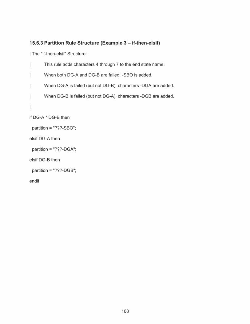
168
15.6.3 Partition Rule Structure (Example 3 – if-then-elsif)
| The "if-then-elsif" Structure:
| This rule adds characters 4 through 7 to the end state name.
| When both DG-A and DG-B are failed, -SBO is added.
| When DG-A is failed (but not DG-B), characters -DGA are added.
| When DG-B is failed (but not DG-A), characters -DGB are added.
|
if DG-A * DG-B then
partition = "???-SBO";
elsif DG-A then
partition = "???-DGA";
elsif DG-B then
partition = "???-DGB";
endif

169
15.6.4 Partition Rule Structure (Example 4 – if-then-elsif-else)
| The "if-then-elsif-else" Structure:
if DG-A * DG-B then
partition = "???-SBO";
elsif DG-A then
partition = "???-DGA";
elsif DG-B then
partition = "???-DGB";
else
partition = "???-FLW";
endif
| Note that the cut sets that do not contain DG-A or DG-B are assigned to the
| ???-FLW endstate by the else statement, since they do not meet the search criteria.
15.6.5 Partition Rule Structure (Example 5 – Macros)
Macros can be used to streamline complex rules. A macro is simply a user-defined keyword that specifies a search criterion that can be used in the rule instead of the individual events (i.e., search criterion). An example is provided below.
| Define a macro named ALL-DGS
ALL-DGS = DG-A * DG-B;
| Use the macro in a rule
if ALL-DGS then
partition = "???-SBO";
endif
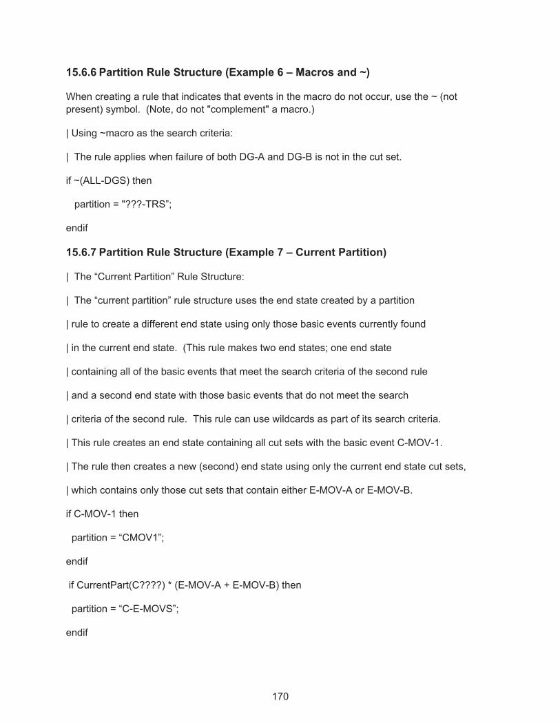
170
15.6.6 Partition Rule Structure (Example 6 – Macros and ~)
When creating a rule that indicates that events in the macro do not occur, use the ~ (not present) symbol. (Note, do not "complement" a macro.)
| Using ~macro as the search criteria:
| The rule applies when failure of both DG-A and DG-B is not in the cut set.
if ~(ALL-DGS) then
partition = "???-TRS”;
endif
15.6.7 Partition Rule Structure (Example 7 – Current Partition)
| The “Current Partition” Rule Structure:
| The “current partition” rule structure uses the end state created by a partition
| rule to create a different end state using only those basic events currently found
| in the current end state. (This rule makes two end states; one end state
| containing all of the basic events that meet the search criteria of the second rule
| and a second end state with those basic events that do not meet the search
| criteria of the second rule. This rule can use wildcards as part of its search criteria.
| This rule creates an end state containing all cut sets with the basic event C-MOV-1.
| The rule then creates a new (second) end state using only the current end state cut sets,
| which contains only those cut sets that contain either E-MOV-A or E-MOV-B.
if C-MOV-1 then
partition = “CMOV1”;
endif
if CurrentPart(C????) * (E-MOV-A + E-MOV-B) then
partition = “C-E-MOVS”;
endif

171
15.6.8 Partition Rule Structure (Example 8 – Global Partition)
| The "GlobalPartition" Rule Structure:
| This rule globally partitions all cut sets in a sequence to an end state.
| This option is activated by using the keyword “GlobalPartition” instead
| of the normal “partition” keyword.
| This partition rule is much faster at gathering cut sets than using
| the normal “partition” rule. This rule is geared more for
| gathering cut sets based upon sequence logic than on
| individual basic events.
| The “GlobalPartition” rule structure is the same as for “partitioning” rules.
| This example “GlobalPartition” rule will gather all sequence cut sets that
| pertain to specified sequence logic.
| Cut sets will be put into an endstate called CD-SEQ2 if they are found in
| sequences that contain the following sequence logic
| LOSP * ECS * /CCS.
| Cut sets will be put into an endstate called CD-SEQ3 if they are found in
| sequences that contain the following sequence logic
| LOSP * ECS * CCS.
|
if INIT(LOSP) * SYSTEM(ECS) * SYSTEM(/CCS) then
GlobalPartition = “CD-SEQ2";
elsif INIT(LOSP) * SYSTEM(ECS) * SYSTEM(CCS) then
GlobalPartition = “CD-SEQ3";
endif

172
The Global Partition rule loads all of the sequence cut sets into the end state in a single pass instead of evaluating each cut set. Consequently, it is recommended to “global partition” based upon initiators or system top events.
If a “global partition” is performed on basic events, all cut sets listed after the basic event’s cut set will be partitioned into the end state.
15.6.9 Partition Rule Structure (Example 9 – Global Partition and Transfer)
Global Partition rules should not be mixed with normal “Partitioning” rules. Global Partition rules are geared more for Level 2 studies since the end state that is created is also an event tree with the same name. The event tree that is created uses the end state frequency as its initiating event frequency and then transfers to a Level 2 event tree. This “end state event tree” can be looked at as an event tree which transfers Level 1 information to Level 2 event trees.
| The “Global Partition” rule to transfer the end state frequency to be used
| by a Level 2 event tree.
| This rule creates an end state event tree to be used by a Level 2 event tree
| (which is already created).
| LEVEL2TREENAME can be viewed as a Level 2 event tree name. This tree
| will use the end state frequency gathered in the end state CD-SEQ3 as
| its initiating event frequency.
if init(LOSP) * SYSTEM(ECS) * SYSTEM(CCS) then
GlobalPartition = “CD-SEQ3";
transfer = LEVEL2TREENAME;
endif
Note:
Global Partitioning is designed for rapidly partitioning cut sets into end states based upon sequence logic. Since individual cut sets are not searched, the Global Partitioning rule is much faster at gathering cut sets than the other partitioning methods.

173
15.7 Partition Rule Keywords and Nomenclature
Each of the “rules” in SAPHIRE (linking, recovery, and partition) has their own nomenclature. The table below lists the keywords available for partition rules.
Keyword or symbol Definition Usage
if then
Keyword that indicates search criteria is being specified.
if "search criteria" then
perform some action on each cut set;
endif
endif
Keyword that indicates the end of a particular rule.
if "search criteria" then
perform some action on each cut set;
endif
else
Keyword that specifies some action to be taken if all the search criteria are not met. The else should be the last condition in the recovery rule.
if "search criteria" then
perform some action on each cut set;
else
perform action on each cut set if
search criteria not met;
endif
elsif
Keyword that specifies an alternative search criteria. Any number of elsifs can be used within a recovery rule.
if "search criteria" then
perform some action on each cut set;
elsif "2nd search criteria" then
perform action on each cut set;
elsif "3rd search criteria" then
perform action on each cut set;
endif
always
Keyword that indicates that every cut set that is being evaluated satisfies the search criteria.
if always then
perform some action on each cut set;
endif
init( )
Keyword used in the search criteria to indicate that a sequence cut set has a particular initiating event.
if init(INITIATOR-NAME) * "other search criteria if needed" then
perform some action on each cut set;
endif
system( )
Keyword used in the search criteria to indicate that the sequence logic contains the particular top event.
if system(TOP EVENT) * “other search criteria if needed” then
perform action on each sequence;
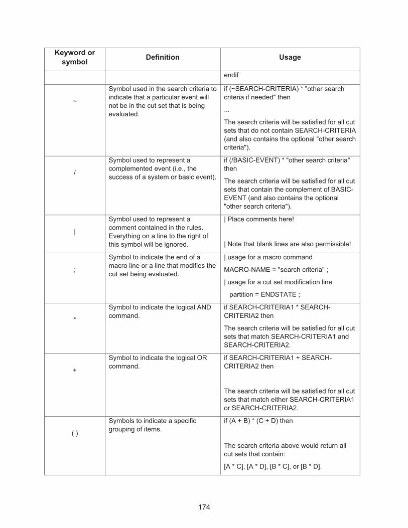
174
Keyword or symbol Definition Usage
endif
~
Symbol used in the search criteria to indicate that a particular event will not be in the cut set that is being evaluated.
if (~SEARCH-CRITERIA) * "other search criteria if needed" then
...
The search criteria will be satisfied for all cut sets that do not contain SEARCH-CRITERIA (and also contains the optional "other search criteria").
/
Symbol used to represent a complemented event (i.e., the success of a system or basic event).
if (/BASIC-EVENT) * "other search criteria" then
The search criteria will be satisfied for all cut sets that contain the complement of BASIC-EVENT (and also contains the optional "other search criteria").
|
Symbol used to represent a comment contained in the rules. Everything on a line to the right of this symbol will be ignored.
| Place comments here!
| Note that blank lines are also permissible!
;
Symbol to indicate the end of a macro line or a line that modifies the cut set being evaluated.
| usage for a macro command
MACRO-NAME = "search criteria" ;
| usage for a cut set modification line
partition = ENDSTATE ;
*
Symbol to indicate the logical AND command.
if SEARCH-CRITERIA1 * SEARCH-CRITERIA2 then
The search criteria will be satisfied for all cut sets that match SEARCH-CRITERIA1 and SEARCH-CRITERIA2.
+
Symbol to indicate the logical OR command.
if SEARCH-CRITERIA1 + SEARCH-CRITERIA2 then
The search criteria will be satisfied for all cut sets that match either SEARCH-CRITERIA1 or SEARCH-CRITERIA2.
( )
Symbols to indicate a specific grouping of items.
if (A + B) * (C + D) then
The search criteria above would return all cut sets that contain:
[A * C], [A * D], [B * C], or [B * D].

175
Keyword or symbol Definition Usage
partition =
Keyword that indicates the end state characters for the cut sets meeting the search criteria will be modified according to the text after the equal sign.
if "search criteria" then
partition = “END_STATE_NAME”;
endif
CurrentPart( )
Keyword that searches for cut sets that have already been assigned to the endstate indicated.
if CurrentPart(CORE-DAMAGE) then
partition = “NEW-CORE-DAMAGE”;
endif
GlobalPartition=
Keyword to indicate that all cut sets in a particular sequence will be assigned to the end state identified after the equal sign.
if "search criteria" then
GlobalPartition = “MY-END-STATE”;
endif
transfer =
Keyword to indicate the event tree to be created and transferred to for the sequence meeting the search criteria. The sequence end state frequency will be used as the initiating event frequency for the new event tree.
if "search criteria" then
GlobalPartition = “CORE-DAMAGE”;
transfer = LEVEL-2-TREE;
endif
MACRO
A macro is a user-definable keyword that specifies search criteria. The macro name must be all upper-case, must be 16 characters or less, and must not include any of the restricted characters (e.g., a space, *, ?, \, /). The macro line can wrap around to more than one line, but must end with a semicolon.
MACRO-NAME = SEARCH-CRITERIA;
if MACRO-NAME then
perform some action on each cut set;
endif
|Macros are only applicable in the particular rule set where they appear

176
15.8 Partition Rule Example
15.8.1 Creating the Partition Rule
A rule for the DEMO project is added by selecting the Project � Edit Rules � End State Partition. The first project rule shown below add characters 1 through 5 as “LOSP-“ when LOSP is the initiating event, and OTHER if LOSP is not the initiating event. The next rule adds characters 13 through 16 as -SBO when both DG-A and DG-B are failed. When DG-A is failed, DGA is added, and when DG-B is failed, DGB is added (as characters in the end state name).
| End State Partitioning Rules Example 1: Project
if init(LOSP) then
Partition = "LOSP-";
else
Partition = "OTHER-";
endif
| End State Partitioning Rules Example 2: Project
if DG-A * DG-B then
Partition = "????????????-SBO";
elsif DG-A then
Partition = "????????????-DGA";
elsif DG-B then
Partition = "????????????-DGB";
endif

177
Rules for LOSP sequences 2 and 3 are entered by right clicking on LOSP in the Event Tree list and selecting Edit Partition Rules, then keying on the top event fault tree CCS as shown below:
Create a rule in sequence 2 to add characters 6 through 12 as ECSONLY and a rule for sequence 3 to add characters 6 through 12 as ECS&CCS by using the following partition rules for the event tree LOSP:
| End State Rule sequence 2
if System(/CCS) then
partition = “?????ECSONLY”;
endif
| End State Rule sequence 3
if System(CCS) then
partition = “?????ECS&CCS”;
endif

178
15.8.2 Applying the Partitioning Rules
To apply the partitioning rules, highlight all of the event trees in the event tree list pane, right click the mouse, and select Solve to open the Solve Cut Sets (ET) window.
Ensure that there is a check in the Apply Partition Rules checkbox and click Solve.
15.8.3 Using End State Analysis to Gather the Partitioned Cut Sets
After applying the partition rules, the partitioned end states will be displayed in the End States list pane. The end states must be "gathered" to solve the cut sets. To “gather” end states, highlight the end states in End States list pane, right click to open the End State menu and select Gather.
When Gather option is selected, specify the end state truncation and solution options. Activate the Cut Set Partition radio button and click Solve.
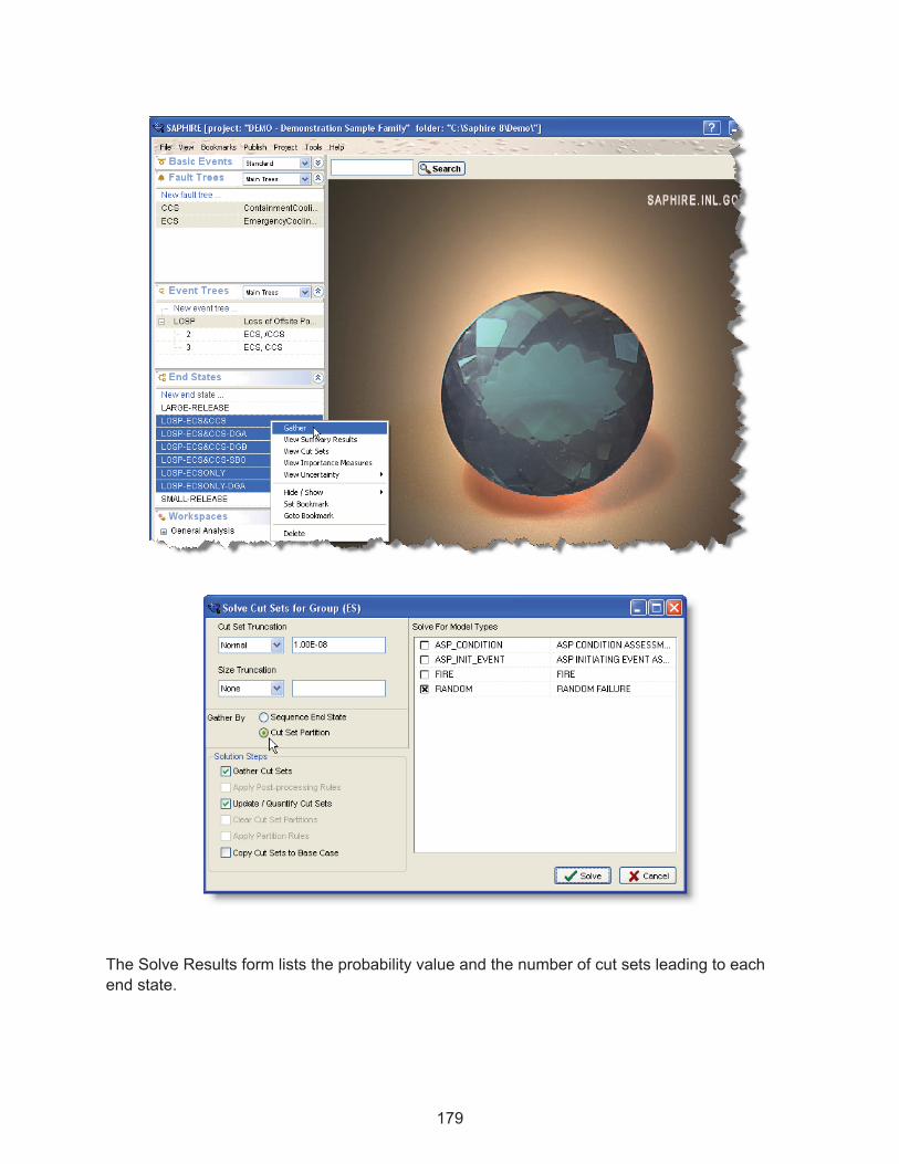
179
The Solve Results form lists the probability value and the number of cut sets leading to each end state.

180
To view the cut sets for an end state, highlight the end state or group of end states and click on Cut Sets.
After the end state cut sets have been solved, uncertainty analysis can be performed by using the End States list menu on a highlighted end state and selecting View Uncertainty.
If the Solve Results form is not active, view previously solved end state cut sets by right clicking on the end state or group of end states in the list pane and selecting View Cut Sets.
15.8.4 Reporting End State Results
End State Cut Set reports can be generated through the View Cut Sets menu by clicking on Report. The report created this way is viewed as html and can be printed or saved. A

181
Summary report type is available by highlighting the end states desired in the End States list pane, right clicking to open the list menu and selecting View Summary Results.
With the end states solved without the partitioning rules, the LARGE-RELEASE and SMALL-RELEASE end states with the uncertainty analysis performed previously generates this report:
By marking the end states that were created by using the partition end state rules, the report shown below was generated.
15.9 Resetting or Deleting Partition Rule End States
To reset the end states created using the partitioning rules, solve the event trees with the Apply Partition Rules check box unchecked and the Clear Cut Set Partitions box checked. This will not delete the partitioned end states, just clear the cut sets from them.
To delete the partitioned end states the event trees need unlinked by highlighting the event tree in the list pane and right clicking to bring up the menu, then selecting Unlink. Similarly, perform a Link again on the event tree and the partitioned end states can then be deleted.
Note:
When comparing end state results to sequence results, differences can occur due to the removal of non-minimal cut sets when cut sets are gathered into the end state.

182

NRC FORM 335 U.S. NUCLEAR REGULATORY COMMISSION
(2-89) NRCM 1102, BIBLIOGRAPHIC DATA SHEET3201. 3202
1. REPORT NUMBER (Assigned by NRC, Add Vol., Supp., Rev., and Addendum Numbers, if any.) NUREG/CR-7039, Vol. 3 INL/EXT-09-17011
2. TITLE AND SUBTITLE 3. DATE REPORT PUBLISHEDSystems Analysis Programs for Hands-on Integrated Reliability Evaluations (SAPHIRE) Version 8
Volume 3: Users Guide
MONTH
MARCH
YEAR
2011
4. FIN OR GRANT NUMBER N6423
5. AUTHOR(S) 6. TYPE OF REPORT
Technical C. L. Smith, K. Vedros, K. J. Kvarfordt 7. PERIOD COVERED
(Inclusive Dates)
8. PERFORMING ORGANIZATION - NAME AND ADDRESS (If NRC, provide Division, Office or Region, U.S. Nuclear Regulatory Commission,and mailing address; if contractor, provide name and mailing address.) Idaho National Laboratory Battelle Energy Alliance P.O. Box 1625 Idaho Falls, ID 83415-3850
9. SPONSORING ORGANIZATION - NAME AND ADDRESS (If NRC, type “Same as above”; If contractor, provide NRC Division, Office or Region,U.S. Nuclear Regulatory Commission, and mailing address.) Division of Risk Analysis Office of Nuclear Regulatory Research U.S. Nuclear Regulatory Commission Washington, DC 20555-0001
10. SUPPLEMENTARY NOTES D. O’Neal, NRC Project Manager
11. ABSTRACT (200 words or less) The Systems Analysis Programs for Hands-on Integrated Reliability Evaluations (SAPHIRE) is a software application developed for performing a complete probabilistic risk assessment (PRA) using a personal computer. SAPHIRE can be used to model a complex system’s response to initiating events, quantify associated damage outcome frequencies, and identify important contributors to this damage (Level 1 PRA) and to analyze containment performance during a severe accident and quantify radioactive releases (Level 2 PRA). This reference guide will introduce the SAPHIRE Version 8.0 software. A brief discussion of the purpose and history of the software is included along with general information such as installation instructions, starting and stopping the program, and some pointers on how to get around inside the program. Next, database concepts and structure are discussed. Following that discussion are nine sections, one for each of the menu options on the SAPHIRE main menu, wherein the purpose and general capabilities for each option are furnished. Next, the capabilities and limitations of the software are provided. 12. KEY WORDS/DESCRIPTORS (List words or phrases that will assist researchers in locating the report.)
AVAILABILITY STATEMENT Unlimited
SAPHIRE 8, software, reliability, risk, safety, PRA, quality assurance 14. SECURITY CLASSIFICATION (This page) Unclassified (This report) Unclassified
15. NUMBER OF PAGES
16. PRICE
NRC FORM 335 (2-89)