Embed Size (px)
Citation preview

System x iDataPlex dx360 M3Types 6385, 6386, and 6391
User's Guide
���


System x iDataPlex dx360 M3Types 6385, 6386, and 6391
User's Guide
���

Note: Before using this information and the product it supports, read the general information in Appendix B, “Notices,” on page 79,the Environmental Notices and User's Guide, and the Warranty and Support Information document on the IBM Documentation CD.
Eighth Edition (October 2011)
© Copyright IBM Corporation 2011.US Government Users Restricted Rights – Use, duplication or disclosure restricted by GSA ADP Schedule Contractwith IBM Corp.
Contents
Safety . . . . . . . . . . . . . . . . . . . . . . . . . . . . vii
Chapter 1. Introduction . . . . . . . . . . . . . . . . . . . . . . 1Related documentation . . . . . . . . . . . . . . . . . . . . . . 2The IBM Documentation CD . . . . . . . . . . . . . . . . . . . . 3
Hardware and software requirements . . . . . . . . . . . . . . . . 3Using the Documentation Browser . . . . . . . . . . . . . . . . . 3
Notices and statements in this document . . . . . . . . . . . . . . . . 4Features and specifications . . . . . . . . . . . . . . . . . . . . . 5What your dx360 M3 system-board tray offers . . . . . . . . . . . . . . 7Reliability, availability, and serviceability . . . . . . . . . . . . . . . . 9IBM Systems Director . . . . . . . . . . . . . . . . . . . . . . 10The UpdateXpress System Packs . . . . . . . . . . . . . . . . . . 10
Chapter 2. Components, features, and controls . . . . . . . . . . . . 13System-board tray components . . . . . . . . . . . . . . . . . . . 14
System-board connectors . . . . . . . . . . . . . . . . . . . . 15System-board jumpers . . . . . . . . . . . . . . . . . . . . . 16
Flexible chassis features . . . . . . . . . . . . . . . . . . . . . 17Hardware configuration examples . . . . . . . . . . . . . . . . . . 19
2U compute server . . . . . . . . . . . . . . . . . . . . . . 192U input/output server . . . . . . . . . . . . . . . . . . . . . 202U storage server . . . . . . . . . . . . . . . . . . . . . . . 203U storage server . . . . . . . . . . . . . . . . . . . . . . . 21
Operator panel controls, connectors, LEDs, and power . . . . . . . . . . 21Front view . . . . . . . . . . . . . . . . . . . . . . . . . 21Rear view . . . . . . . . . . . . . . . . . . . . . . . . . . 23
Turning on the system-board tray . . . . . . . . . . . . . . . . . . 23Turning off the system-board tray . . . . . . . . . . . . . . . . . . 23
Chapter 3. Installing optional devices. . . . . . . . . . . . . . . . 25Instructions for IBM Business Partners . . . . . . . . . . . . . . . . 25Installation guidelines . . . . . . . . . . . . . . . . . . . . . . 26
System reliability guidelines . . . . . . . . . . . . . . . . . . . 27Handling static-sensitive devices . . . . . . . . . . . . . . . . . 27
Removing a 3U chassis from an iDataPlex rack . . . . . . . . . . . . . 28Removing a system-board tray from a 2U chassis . . . . . . . . . . . . 29Removing a system-board tray from a 3U chassis . . . . . . . . . . . . 30Removing the system-board tray cover . . . . . . . . . . . . . . . . 31Removing an expansion enclosure . . . . . . . . . . . . . . . . . 32Removing a hard disk drive . . . . . . . . . . . . . . . . . . . . 33
Removing a 3.5-inch hot-swap hard disk drive . . . . . . . . . . . . 33Removing a 3.5-inch simple-swap hard disk drive . . . . . . . . . . . 33Removing a 2.5-inch hot-swap hard disk drive . . . . . . . . . . . . 34Removing a 2.5-inch simple-swap hard disk drive or solid-state drive . . . . 35
Installing an adapter . . . . . . . . . . . . . . . . . . . . . . . 35Installing an outer adapter in the I/O enclosure . . . . . . . . . . . . 36Installing an inner adapter in the I/O enclosure (some configurations) . . . . 40Installing an adapter to a front PCI riser-card assembly . . . . . . . . . 41Installing a ServeRAID-M1015 to a rear storage PCI riser-card assembly 43Installing a rear PCIe riser-card assembly in the system-board tray. . . . . 44
Installing a hard disk drive. . . . . . . . . . . . . . . . . . . . . 45Installing a 3.5-inch hot-swap hard disk drive . . . . . . . . . . . . . 45
© Copyright IBM Corp. 2011 iii

Installing a 3.5-inch simple-swap hard disk drive . . . . . . . . . . . 45Installing a 2.5-inch hot-swap hard disk drive . . . . . . . . . . . . . 46Installing a 2.5-inch simple-swap hard disk drive or solid-state drive . . . . 47
Installing a memory module . . . . . . . . . . . . . . . . . . . . 48Installing an IBM virtual media key. . . . . . . . . . . . . . . . . . 52Completing the installation. . . . . . . . . . . . . . . . . . . . . 53
Reinstalling the system-board tray cover . . . . . . . . . . . . . . 53Reinstalling an expansion enclosure . . . . . . . . . . . . . . . . 54Reinstalling a system-board tray in a 2U chassis . . . . . . . . . . . 55Reinstalling a system-board tray in a 3U chassis . . . . . . . . . . . 56Reinstalling a 3U chassis in an iDataPlex rack . . . . . . . . . . . . 58Connecting the cables . . . . . . . . . . . . . . . . . . . . . 59Updating the server configuration . . . . . . . . . . . . . . . . . 59
Chapter 4. Configuring the dx360 M3 server . . . . . . . . . . . . . 61Using the Setup utility . . . . . . . . . . . . . . . . . . . . . . 62
Starting the Setup utility . . . . . . . . . . . . . . . . . . . . 63Setup utility menu choices. . . . . . . . . . . . . . . . . . . . 63Passwords . . . . . . . . . . . . . . . . . . . . . . . . . 66
Using the Boot Menu program . . . . . . . . . . . . . . . . . . . 67Starting the backup UEFI firmware . . . . . . . . . . . . . . . . . 67Using the integrated management module . . . . . . . . . . . . . . . 68Using the remote presence capability and blue-screen capture . . . . . . . 69
Enabling the remote presence feature . . . . . . . . . . . . . . . 69Obtaining the IP address for the Web interface access . . . . . . . . . 70Logging on to the Web interface . . . . . . . . . . . . . . . . . 70
IBM Advanced Settings Utility program . . . . . . . . . . . . . . . . 71Configuring the Gigabit Ethernet controller . . . . . . . . . . . . . . . 71Using the LSI Logic Configuration Utility program . . . . . . . . . . . . 72
Starting the LSI Logic Configuration Utility program . . . . . . . . . . 73Formatting a SCSI hard disk drive . . . . . . . . . . . . . . . . . 73Creating a mirrored pair of SCSI hard disk drives . . . . . . . . . . . 73
Configuring a ServeRAID controller . . . . . . . . . . . . . . . . . 74Firmware updates . . . . . . . . . . . . . . . . . . . . . . . . 74Updating IBM Systems Director . . . . . . . . . . . . . . . . . . . 75
Appendix A. Getting help and technical assistance . . . . . . . . . . 77Before you call . . . . . . . . . . . . . . . . . . . . . . . . . 77Using the documentation . . . . . . . . . . . . . . . . . . . . . 77Getting help and information from the World Wide Web . . . . . . . . . . 78Software service and support . . . . . . . . . . . . . . . . . . . 78Hardware service and support . . . . . . . . . . . . . . . . . . . 78IBM Taiwan product service . . . . . . . . . . . . . . . . . . . . 78
Appendix B. Notices . . . . . . . . . . . . . . . . . . . . . . 79Trademarks . . . . . . . . . . . . . . . . . . . . . . . . . . 79Important notes. . . . . . . . . . . . . . . . . . . . . . . . . 80Particulate contamination . . . . . . . . . . . . . . . . . . . . . 81Documentation format . . . . . . . . . . . . . . . . . . . . . . 81Telecommunication regulatory statement . . . . . . . . . . . . . . . 82Electronic emission notices . . . . . . . . . . . . . . . . . . . . 82
Federal Communications Commission (FCC) statement . . . . . . . . . 82Industry Canada Class A emission compliance statement . . . . . . . . 82Avis de conformité à la réglementation d'Industrie Canada . . . . . . . . 82Australia and New Zealand Class A statement . . . . . . . . . . . . 82European Union EMC Directive conformance statement . . . . . . . . . 83
iv System x iDataPlex dx360 M3: User's Guide

Germany Class A statement . . . . . . . . . . . . . . . . . . . 83Japan VCCI Class A statement . . . . . . . . . . . . . . . . . . 84Japan Electronics and Information Technology Industries Association (JEITA)
statement . . . . . . . . . . . . . . . . . . . . . . . . . 84Korea Communications Commission (KCC) statement . . . . . . . . . 84Russia Electromagnetic Interference (EMI) Class A statement. . . . . . . 85People's Republic of China Class A electronic emission statement . . . . . 85Taiwan Class A compliance statement . . . . . . . . . . . . . . . 85
Index . . . . . . . . . . . . . . . . . . . . . . . . . . . . 87
Contents v

vi System x iDataPlex dx360 M3: User's Guide

Safety
Before installing this product, read the Safety Information.
Antes de instalar este produto, leia as Informações de Segurança.
Pred instalací tohoto produktu si prectete prírucku bezpecnostních instrukcí.
Læs sikkerhedsforskrifterne, før du installerer dette produkt.
Lees voordat u dit product installeert eerst de veiligheidsvoorschriften.
Ennen kuin asennat tämän tuotteen, lue turvaohjeet kohdasta Safety Information.
Avant d'installer ce produit, lisez les consignes de sécurité.
Vor der Installation dieses Produkts die Sicherheitshinweise lesen.
Prima di installare questo prodotto, leggere le Informazioni sulla Sicurezza.
Les sikkerhetsinformasjonen (Safety Information) før du installerer dette produktet.
Antes de instalar este produto, leia as Informações sobre Segurança.
Antes de instalar este producto, lea la información de seguridad.
Läs säkerhetsinformationen innan du installerar den här produkten.
© Copyright IBM Corp. 2011 vii
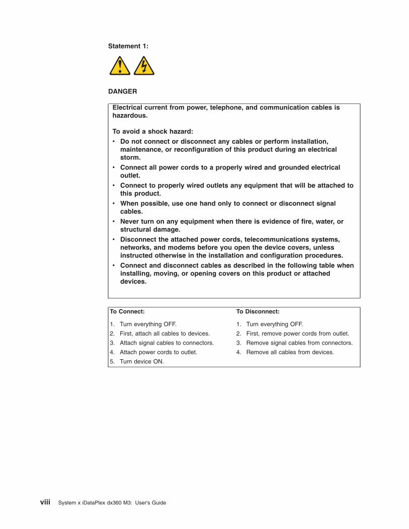
Statement 1:
DANGER
Electrical current from power, telephone, and communication cables ishazardous.
To avoid a shock hazard:
v Do not connect or disconnect any cables or perform installation,maintenance, or reconfiguration of this product during an electricalstorm.
v Connect all power cords to a properly wired and grounded electricaloutlet.
v Connect to properly wired outlets any equipment that will be attached tothis product.
v When possible, use one hand only to connect or disconnect signalcables.
v Never turn on any equipment when there is evidence of fire, water, orstructural damage.
v Disconnect the attached power cords, telecommunications systems,networks, and modems before you open the device covers, unlessinstructed otherwise in the installation and configuration procedures.
v Connect and disconnect cables as described in the following table wheninstalling, moving, or opening covers on this product or attacheddevices.
To Connect: To Disconnect:
1. Turn everything OFF.
2. First, attach all cables to devices.
3. Attach signal cables to connectors.
4. Attach power cords to outlet.
5. Turn device ON.
1. Turn everything OFF.
2. First, remove power cords from outlet.
3. Remove signal cables from connectors.
4. Remove all cables from devices.
viii System x iDataPlex dx360 M3: User's Guide
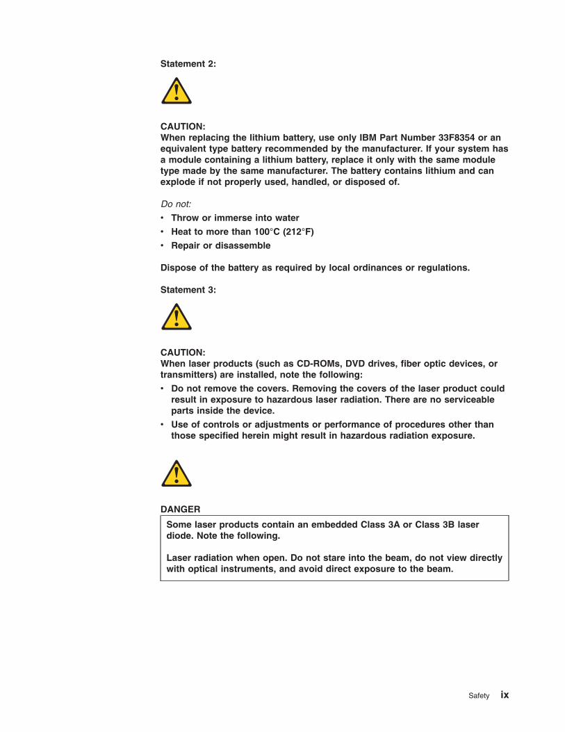
Statement 2:
CAUTION:When replacing the lithium battery, use only IBM Part Number 33F8354 or anequivalent type battery recommended by the manufacturer. If your system hasa module containing a lithium battery, replace it only with the same moduletype made by the same manufacturer. The battery contains lithium and canexplode if not properly used, handled, or disposed of.
Do not:
v Throw or immerse into water
v Heat to more than 100°C (212°F)
v Repair or disassemble
Dispose of the battery as required by local ordinances or regulations.
Statement 3:
CAUTION:When laser products (such as CD-ROMs, DVD drives, fiber optic devices, ortransmitters) are installed, note the following:
v Do not remove the covers. Removing the covers of the laser product couldresult in exposure to hazardous laser radiation. There are no serviceableparts inside the device.
v Use of controls or adjustments or performance of procedures other thanthose specified herein might result in hazardous radiation exposure.
DANGER
Some laser products contain an embedded Class 3A or Class 3B laserdiode. Note the following.
Laser radiation when open. Do not stare into the beam, do not view directlywith optical instruments, and avoid direct exposure to the beam.
Safety ix

Statement 4:
≥ 18 kg (39.7 lb) ≥ 32 kg (70.5 lb) ≥ 55 kg (121.2 lb)
CAUTION:Use safe practices when lifting.
Statement 5:
CAUTION:The power control button on the device and the power switch on the powersupply do not turn off the electrical current supplied to the device. The devicealso might have more than one power cord. To remove all electrical currentfrom the device, ensure that all power cords are disconnected from the powersource.
1 2
x System x iDataPlex dx360 M3: User's Guide

Statement 8:
CAUTION:Never remove the cover on a power supply or any part that has the followinglabel attached.
Hazardous voltage, current, and energy levels are present inside anycomponent that has this label attached. There are no serviceable parts insidethese components. If you suspect a problem with one of these parts, contacta service technician.
Statement 10:
CAUTION:Do not place any object on top of rack-mounted devices.
Safety xi

xii System x iDataPlex dx360 M3: User's Guide

Chapter 1. Introduction
IBM® System x™ iDataPlex™ products are ideally suited for data-centerenvironments that require high-performance, energy-efficient, cost-effectivehardware. The modular design of the iDataPlex components makes it possible foryou to order customized server solutions that meet the specific needs of yourcurrent environment.
This User's Guide contains general information about how to use, upgrade, andconfigure the components in your customized server solution. These componentsconsist of the IBM System x iDataPlex dx360 M3 system-board tray (dx360 M3Type 6391 system-board tray), an IBM System x iDataPlex 2U Flex Chassis (Type6385 2U chassis) or an IBM System x iDataPlex 3U Chassis (Type 6386 3Uchassis), the IBM System x iDataPlex Storage enclosure (storage enclosure), andthe IBM System x iDataPlex I/O enclosure (I/O enclosure).
Depending on what you ordered, you received one or more of the following serversolutions:
v Two dx360 M3 system-board trays installed in a 2U chassis
v One dx360 M3 system-board tray and one storage enclosure installed in a 2Uchassis
v One dx360 M3 system-board tray and one I/O enclosure installed in a 2Uchassis
v One dx360 M3 system-board tray installed in a 3U chassis
See Chapter 2, “Components, features, and controls,” on page 13 for detailedinformation about the components in the customized server solutions.
The iDataPlex products come with a limited warranty. For information about theterms of the warranty and getting service and assistance, see the Warranty andSupport Information document.
You can obtain up-to-date information about the IBM iDataPlex products and otherIBM server products at http://www.ibm.com/systems/x/.
If you participate in the IBM client reference program, you can share informationabout your use of technology, best practices, and innovative solutions; build aprofessional network; and gain visibility for your business. For more informationabout the IBM client reference program, see http://www.ibm.com/ibm/clientreference/.
At http://www.ibm.com/support/mysupport/, you can create a personalized supportpage by identifying IBM products that are of interest to you. From this personalizedpage, you can subscribe to weekly e-mail notifications about new technicaldocuments, search for information and downloads, and access variousadministrative services.
The system-board tray serial number is on a label at the front of the system-boardtray. The system-board tray integrated management module (IMM) media accesscontrol (MAC) address is on a tab at the right side of the system-board tray. Thechassis machine type and serial number are on a label on the front of the chassisat the right side.
© Copyright IBM Corp. 2011 1
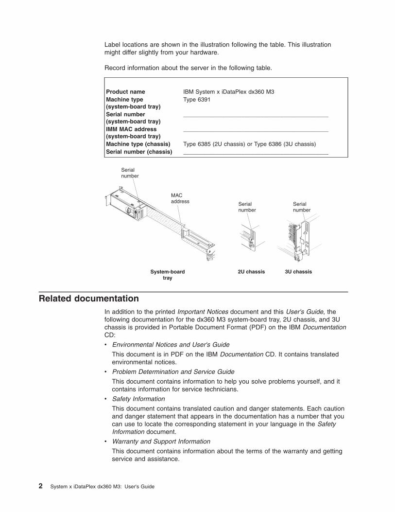
Label locations are shown in the illustration following the table. This illustrationmight differ slightly from your hardware.
Record information about the server in the following table.
Product name IBM System x iDataPlex dx360 M3Machine type(system-board tray)
Type 6391
Serial number(system-board tray)
_____________________________________________
IMM MAC address(system-board tray)
_____________________________________________
Machine type (chassis) Type 6385 (2U chassis) or Type 6386 (3U chassis)Serial number (chassis) _____________________________________________
Related documentationIn addition to the printed Important Notices document and this User's Guide, thefollowing documentation for the dx360 M3 system-board tray, 2U chassis, and 3Uchassis is provided in Portable Document Format (PDF) on the IBM DocumentationCD:
v Environmental Notices and User's Guide
This document is in PDF on the IBM Documentation CD. It contains translatedenvironmental notices.
v Problem Determination and Service Guide
This document contains information to help you solve problems yourself, and itcontains information for service technicians.
v Safety Information
This document contains translated caution and danger statements. Each cautionand danger statement that appears in the documentation has a number that youcan use to locate the corresponding statement in your language in the SafetyInformation document.
v Warranty and Support Information
This document contains information about the terms of the warranty and gettingservice and assistance.
2 System x iDataPlex dx360 M3: User's Guide
Depending on the hardware configuration, additional documentation might beincluded on the IBM Documentation CD.
The iDataPlex documentation might be updated occasionally, or technical updatesmight be available to provide additional information that is not included in thedocumentation. These updates are available from the IBM Systems InformationCenter. To check for updated iDataPlex information and technical updates, go tohttp://publib.boulder.ibm.com/infocenter/idataplx/documentation/index.jsp.
The updated iDataPlex documentation also is available from the IBM Support Website. To check for updated documentation and technical updates, complete thefollowing steps.
Note: Changes are made periodically to the IBM Web site. The actual proceduremight vary slightly from what is described in this document.
1. Go to http://www.ibm.com/systems/support/.
2. Under Product support, click System x.
3. Under Popular links, click Publications lookup.
4. From the Product family menu, select System x iDataPlex dx360 M3 serverand click Go.
The IBM Documentation CDThe IBM Documentation CD contains documentation in Portable Document Format(PDF) and includes the IBM Documentation Browser to help you find informationquickly.
Hardware and software requirementsThe IBM Documentation CD requires the following minimum hardware andsoftware:
v Microsoft Windows XP, Windows 2000, or Red Hat Linux
v 100 MHz microprocessor
v 32 MB of RAM
v Adobe Acrobat Reader 3.0 (or later) or xpdf, which comes with Linux operatingsystems
Using the Documentation BrowserUse the Documentation Browser to browse the contents of the CD, read briefdescriptions of the documents, and view documents, using Adobe Acrobat Readeror xpdf. The Documentation Browser automatically detects the regional settings inyour server and displays the documents in the language for that region (ifavailable). If a document is not available in the language for that region, theEnglish-language version is displayed.
Use one of the following procedures to start the Documentation Browser:
v If Autostart is enabled, insert the CD into the CD or DVD drive. TheDocumentation Browser starts automatically.
v If Autostart is disabled or is not enabled for all users, use one of the followingprocedures:
– If you are using a Windows operating system, insert the CD into the CD orDVD drive and click Start --> Run. In the Open field, typee:\win32.bat
Chapter 1. Introduction 3

where e is the drive letter of the CD or DVD drive, and click OK.
– If you are using Red Hat Linux, insert the CD into the CD or DVD drive; then,run the following command from the /mnt/cdrom directory:sh runlinux.sh
Select the device from the Product menu. The Available Topics list displays all thedocuments for the devices. Some documents might be in folders. A plus sign (+)indicates each folder or document that has additional documents under it. Click theplus sign to display the additional documents.
When you select a document, a description of the document is displayed underTopic Description. To select more than one document, press and hold the Ctrl keywhile you select the documents. Click View Book to view the selected document ordocuments in Acrobat Reader or xpdf. If you selected more than one document, allthe selected documents are opened in Acrobat Reader or xpdf.
To search all the documents, type a word or word string in the Search field andclick Search. The documents in which the word or word string appears are listed inorder of the most occurrences. Click a document to view it, and press Crtl+F to usethe Acrobat search function, or press Alt+F to use the xpdf search function withinthe document.
Click Help for detailed information about using the Documentation Browser.
Notices and statements in this documentThe caution and danger statements in this document are also in the multilingualSafety Information document, which is on the IBM Documentation CD. Eachstatement is numbered for reference to the corresponding statement in yourlanguage in the Safety Information document.
The following notices and statements are used in this document:
v Note: These notices provide important tips, guidance, or advice.
v Important: These notices provide information or advice that might help you avoidinconvenient or problem situations.
v Attention: These notices indicate potential damage to programs, devices, ordata. An attention notice is placed just before the instruction or situation in whichdamage might occur.
v Caution: These statements indicate situations that can be potentially hazardousto you. A caution statement is placed just before the description of a potentiallyhazardous procedure step or situation.
v Danger: These statements indicate situations that can be potentially lethal orextremely hazardous to you. A danger statement is placed just before thedescription of a potentially lethal or extremely hazardous procedure step orsituation.
4 System x iDataPlex dx360 M3: User's Guide

Features and specificationsThe following information is a summary of the features and specifications of thehardware. Depending on the hardware configuration, some features might not beavailable, or some specifications might not apply.
Racks are marked in vertical increments of 4.45 cm (1.75 inches). Each incrementis referred to as a unit, or “U.” A 1U-high device is 1.75 inches tall.
Chapter 1. Introduction 5

Microprocessor: One or two up tosix-core Intel Xeon microprocessorswith integrated memory controllers ineach system-board trayNote: Use the Setup utility todetermine the type and speed of themicroprocessor.
Hard disk drives: The system-boardtray supports one 3.5-inchsimple-swap SAS (with the optionalSAS controller), one 3.5-inchsimple-swap SATA, or two 2.5-inchsimple-swap SATA hard disk drives orsolid-state drives. The system-boardtray with an attached enclosure cansupport the following driveconfigurations:
v Up to four 3.5-inch simple-swapSAS or SATA hard disk drives withthe storage enclosure and optionalSAS controller
v Up to five 3.5-inch simple-swapSATA hard disk drives with thestorage enclosure
v Up to eight 2.5-inch simple-swapSATA/SAS or solid-state hard diskdrives (with an optional RAIDcontroller) with the storageenclosure
v Up to two 3.5-inch simple-swapSATA hard disk drives with the I/Oenclosure
v Up to two 3.5-inch simple-swapSAS hard disk drives with the I/Oenclosure and optional SAScontroller
v Up to four 2.5-inch simple-swapSATA/SAS or solid-state hard diskdrives (with an optional RAIDcontroller) with the I/O enclosure
v Up to twelve 3.5-inch hot-swapSAS or SATA (with the optionalSAS controller) hard disk drives ina 3U chassis
Memory:v Sixteen DIMM connectors (eight
per microprocessor)v Minimum: Two DIMMs per
microprocessorv Maximum: 192 GBv Type: Registered ECC
double-data-rate 3 (DDR3) -800,-1066, and -1333 MHz DIMMs,1.5V RDIMMs or 1.35V capableRDIMMs
v Sizes: 2 GB single-rank/dual-rank,4 GB dual-rank, 8 GB dual-rank,and 16 GB quad-rank
v Chipkill supported with selectedDIMMs
Integrated functions:v Integrated management module
(IMM), which provides serviceprocessor control and monitoringfunctions, video controller, and(when the optional virtual mediakey is installed) remote keyboard,video, mouse, and remote harddisk drive capabilities
v Dedicated or shared managementnetwork connections
v Integrated Trusted PlatformModule (TPM) support
v Six Serial ATA (SATA) portsv Serial over LAN (SOL) and serial
redirection over Telnet or SecureShell (SSH)
v Dual-port Gigabit Ethernetcontroller
v Front connectors for USB 2.0 (2ports), serial, video, and RJ-45 (3ports)– One systems-management
RJ-45 port for connection to adedicated systems-management network
– Two RJ-45 LAN ports
Predictive Failure Analysis (PFA)alerts:v Memoryv Hard disk drives
Expansion slots: Up to two PCIExpress slots total. Support for thefollowing riser cards:v One PCI Express x16 slot (x16)v Two PCI Express x16 slots(x16) with
one PCI Express x8 slot (x8)v One PCI Express x8 slot (x8)
supports an optional RAID controlleronly (some configurations)
Environment:
v Air temperature:– Server on: 10°C to 35°C (50°F to
95°F); altitude: 0 to 914.4 m (0 to3000 ft). Derate maximumtemperature by 1°C for every304.8 m (1000 ft) increase inelevation to a maximum of 3048.0m (10000 ft) at an ambienttemperature of 28°C
– Server off: 10°C to 43°C (59°F to109.4°F); maximum altitude: 2133m (7000 ft)
v Humidity:– Server on: 10% to 80%– Server off: 8% to 80%
Size:
v Height:– 2U chassis: 8.6 cm (3.39 inches)– 3U chassis: 13.0 cm (5.1 inches)
v Depth: 51.3 cm (20.2 inches)
v Width: 44.6 cm (17.6 inches)
v Weight:– 2U chassis:
- Fully loaded: 22.7 kg (46.1 lb)- Without system-board trays:
7.1 kg (15.6 lb)– 3U chassis:
- Fully loaded: 28.1 kg (62.0 lb)- Without hard disk drives: 15.4
kg (34.0 lb)
Electrical Input:
v Input voltage low range (notapplicable to 750 W dual AC inputpower supply): 100 V ac (minimum)to 127 V ac (maximum), sine-waveinput (50 - 60 Hz)
v Input voltage high range: 200 V ac(minimum) to 240 V ac (maximum),sine-wave input (50 - 60 Hz)
6 System x iDataPlex dx360 M3: User's Guide

What your dx360 M3 system-board tray offersThe dx360 M3 system-board tray uses the following features and technologies:
v Active PCI Express x16 Generation 2 adapter capabilities
The dx360 M3 system-board tray has up to three connectors for PCI Expressadapters on up to three riser cards. These connectors accept x8 or x16 adapters.
v Dynamic System Analysis (DSA) programs
The DSA programs collect and analyze system information to aid in diagnosingproblems. The diagnostic programs collect the following information:
– System configuration
– Network interfaces and settings
– Installed hardware
– Service processor status and configuration
– Vital product data, firmware, and Unified Extensible Firmware Interface (UEFI)configuration
– Hard disk drive health
– RAID controller configuration
– Event logs for ServeRAID controllers and service processors
The diagnostic programs create a merged log that includes events from allcollected logs. The information is collected into a file that you can send to IBMservice and support. Additionally, you can view the information locally through agenerated text report file. You can also copy the log to removable media andview the log from a Web browser.
v Integrated management module
The integrated management module (IMM) combines service processorfunctions, video controller, and (when an optional virtual media key is installed)remote presence function in a single chip. The IMM provides advancedservice-processor control, monitoring, and alerting function. If an environmentalcondition exceeds a threshold or if a system component fails, the IMM lightsLEDs to help you diagnose the problem, records the error in the event log, andalerts you to the problem. Optionally, the IMM also provides a virtual presencecapability for remote server management capabilities. The IMM provides remoteserver management through industry-standard interfaces:
– Intelligent Platform Management Interface (IPMI) version 2.0
– Simple Network Management Protocol (SNMP) version 3
– Common Information Model (CIM)
– Web browser
v Integrated network support
The dx360 M3 system-board tray comes with an integrated Intel dual-port GigabitEthernet controller, which supports connection to a 10 Mbps, 100 Mbps, or 1000Mbps network. For more information, see “Configuring the Gigabit Ethernetcontroller” on page 71.
v Integrated Trusted Platform Module (TPM)
This integrated security chip performs cryptographic functions and stores privateand public secure keys. It provides the hardware support for the TrustedComputing Group (TCG) specification. You can download the software to supportthe TCG specification, when the software is available. See http://www.ibm.com/servers/eserver/xseries/scalable_family.html for details about the TPMimplementation. You can enable TPM support through the Setup utility under theSystem Security menu choice.
Chapter 1. Introduction 7

v Large data-storage capacity and hot-swap capability
The dx360 M3 system-board tray supports one 3.5-inch simple-swap SAS, one3.5-inch simple-swap SATA, or two 2.5-inch simple-swap SAS hard disk drives,or SATA hard disk drives, or solid-state drives. An optional SAS controller mustbe installed when you use SAS hard disk drives.
With the storage enclosure attached, the system-board tray can support up tofour 3.5-inch SATA or up to four 3.5-inch simple-swap SAS (with optional SAScontroller) hard disk drives, or five simple-swap SATA hard disk drives, or eight2.5-inch simple-swap SAS hard disk drives, or simple-swap SATA hard diskdrives, or solid-state hard disk.
With the I/O enclosure attached, the system-board tray can support up to two3.5-inch simple-swap SATA hard disk drives, or up to two 3.5-inch simple-swapSAS hard disk drives (with optional SAS controller), or up to four 2.5-inchsimple-swap SAS hard disk drives, or simple-swap SATA hard disk drives, orsolid-state hard disk drives, with optional RAID controller.
When it is installed in a 3U chassis, the system-board tray can support up totwelve 3.5-inch hot-swap SAS (with optional SAS controller) or SATA hard diskdrives. With the hot-swap feature, you can remove or replace hard disk driveswithout turning off the dx360 M3 server.
v Large system-memory capacity
The dx360 M3 system-board tray supports up to 128 GB of system memory (asof the date of this publication). The memory controller supports up to 16industry-standard, registered ECC double-data-rate 3 (DDR3) -800, -1066, and-1333 MHz DIMMs, 1.5V RDIMMs or 1.35V capable RDIMMs.
v Redundant connection
The addition of an optional network interface card (NIC) provides a failovercapability to a redundant Ethernet connection. If a problem occurs with theprimary Ethernet connection, all Ethernet traffic that is associated with theprimary connection is automatically switched to the redundant NIC. If theapplicable device drivers are installed, this switching occurs without data loss andwithout user intervention.
v Remote presence capability and blue-screen capture
The optional virtual media key is required to enable the remote presence andblue-screen capture features. The remote presence feature provides the followingfunctions:
– Remotely viewing video with graphics resolutions up to 1280 x 1024 at 75 Hz,regardless of the system state
– Remotely accessing the server, using the keyboard and mouse from a remoteclient
– Mapping the CD or DVD drive, diskette drive, and USB flash drive on aremote client, and mapping ISO and diskette image files as virtual drives thatare available for use by the server
– Uploading a diskette image to the IMM memory and mapping it to the serveras a virtual drive
The blue-screen capture feature captures the video display contents before theIMM restarts the server when the IMM detects an operating-system hangcondition. A system administrator can use the blue-screen capture to assist indetermining the cause of the hang condition.
v ServeRAID support
The dx360 M3 system-board tray supports ServeRAID adapters to createredundant array of independent disks (RAID) configurations.
8 System x iDataPlex dx360 M3: User's Guide
v Symmetric multiprocessing (SMP)
The dx360 M3 system-board tray comes with one or two Intel microprocessors. Ifthe system-board tray comes with only one microprocessor, a trained servicetechnician can add a second microprocessor.
v Systems-management capabilities
The dx360 M3 system-board tray supports IPMI version 2.0 over LANsystems-management protocol. It supports an optional rack-level managementcontroller that uses industry-standard management tools.
Reliability, availability, and serviceabilityThree important hardware and software design features are reliability, availability,and serviceability (RAS). The RAS features help to ensure the integrity of the datathat is stored in the hardware, the availability of the hardware and software whenyou need it, and the ease with which you can diagnose and correct problems.
The dx360 M3 has the following RAS features:
v Advanced Configuration and Power Interface (ACPI)
v Advanced Desktop Management Interface (DMI) features
v Automatic error retry or recovery
v Automatic restart after a power failure, based on the UEFI setting
v Built in, menu-driven setup, system configuration, and redundant array ofindependent disks (RAID) configuration (depending on server configuration)
v Built-in monitoring of fan, power, temperature, and voltage
v CD-based diagnostic programs
v Customer support center that is available 24 hours a day, 7 days a week1
v Diagnostic support of ServeRAID adapters
v Error codes and messages
v Hot-swap Serial Attached SCSI (SAS) hard disk drives (some configurations)
v Integrated Ethernet controller
v Integrated management module (IMM)
v Power-on self-test (POST) with error logging of POST failures
v Power management
v 750 watt dual AC input power supplies
v Read-only memory (ROM) checksums
v Redundant Ethernet capabilities with failover support
v Remote system problem-determination support
v Simple-swap Serial Advanced Technology Attachment (SATA) hard disk drives(some configurations)
v Simple-swap Serial Attached SCSI (SAS) hard disk drives (some configurations)
v Standby voltage for systems-management features and monitoring
v Startup from backup UEFI page
v System-error LED on the front bezel
v System-error logging
v Upgradeable IMM firmware
1. Service availability will vary by country. Response time varies; may exclude holidays.
Chapter 1. Introduction 9
v Upgradeable microcode for POST, UEFI code, and ROM resident code, locally orover a LAN
v Vital product data (VPD); includes firmware revision numbers, stored innonvolatile memory, for easier remote maintenance
IBM Systems DirectorIBM Systems Director is a platform-management foundation that streamlines theway you manage physical and virtual systems in a heterogeneous environment. Byusing industry standards, IBM Systems Director supports multiple operating systemsand virtualization technologies in IBM and non-IBM x86 platforms.
Through a single user interface, IBM Systems Director provides consistent views forviewing managed systems, determining how these systems relate to one another,and identifying their statuses, helping to correlate technical resources with businessneeds. A set of common tasks that are included with IBM Systems Director providesmany of the core capabilities that are required for basic management, which meansinstant out-of-the-box business value. These common tasks include discovery,inventory, configuration, system health, monitoring, updates, event notification, andautomation for managed systems.
The IBM Systems Director Web and command-line interfaces provide a consistentinterface that is focused on driving these common tasks and capabilities:
v Discovering, navigating, and visualizing systems on the network with the detailedinventory and relationships to the other network resources
v Notifying users of problems that occur on systems and the ability to isolate thesources of the problems
v Notifying users when systems need updates and distributing and installingupdates on a schedule
v Analyzing real-time data for systems and setting critical thresholds that notify theadministrator of emerging problems
v Configuring settings of a single system and creating a configuration plan that canapply those setting to multiple systems
v Updating installed plug-ins to add new features and functions to the basecapabilities
v Managing the life cycles of virtual resources
For more information about IBM Systems Director, see the documentation on theIBM Systems Director CD that comes with the server and the IBM xSeries SystemsManagement Web page at http://www.ibm.com/systems/management/, whichpresents an overview of IBM Systems Management and IBM Systems Director.
The UpdateXpress System PacksThe UpdateXpress System Packs provide an effective and simple way to updatedevice drivers, server firmware, and firmware of supported options contained withinthe server, for System x® and IBM BladeCenter® servers. Each UpdateXpressSystem Pack contains all the online driver and firmware updates for a specificmachine type and operating system combination. The UpdateXpress System Packsare released quarterly. Use the UpdateXpress System Pack Installer to install thecurrent UpdateXpress System Pack for your server.
10 System x iDataPlex dx360 M3: User's Guide

Important: Some cluster solutions require specific code levels or coordinated codeupdates. If the device is part of a cluster solution, verify that the latest level of codeis supported for the cluster solution before you update the code.
You can download the installer and the latest UpdateXpress System Pack for yourserver from the Web at no additional cost. To download the installer or the latestUpdateXpress System Pack, go to http://www.ibm.com/systems/support/supportsite.wss/docdisplay?lndocid=SERV-XPRESS&brandind=5000008 orcomplete the following steps.
Note: Changes are made periodically to the IBM Web site. The actual proceduremight vary slightly from what is described in this document.
1. Got to http://www.ibm.com/systems/support/.
2. Under Product support, click System x.
3. Under Popular links, click Software and device drivers.
4. Under Related downloads, click UpdateXpress.
Note: To install the UpdateXpress program, you might have to use an externalUSB CD-RW/DVD drive such as the IBM and Lenovo part number 73P4515 or73P4516. See “Firmware updates” on page 74 for additional instructions aboutusing an external USB CD-RW/DVD drive.
Chapter 1. Introduction 11

12 System x iDataPlex dx360 M3: User's Guide

Chapter 2. Components, features, and controls
This section describes the server components and configurations, the servercontrols and light-emitting diodes (LEDs), and how to turn the system-board tray onand off.
© Copyright IBM Corp. 2011 13
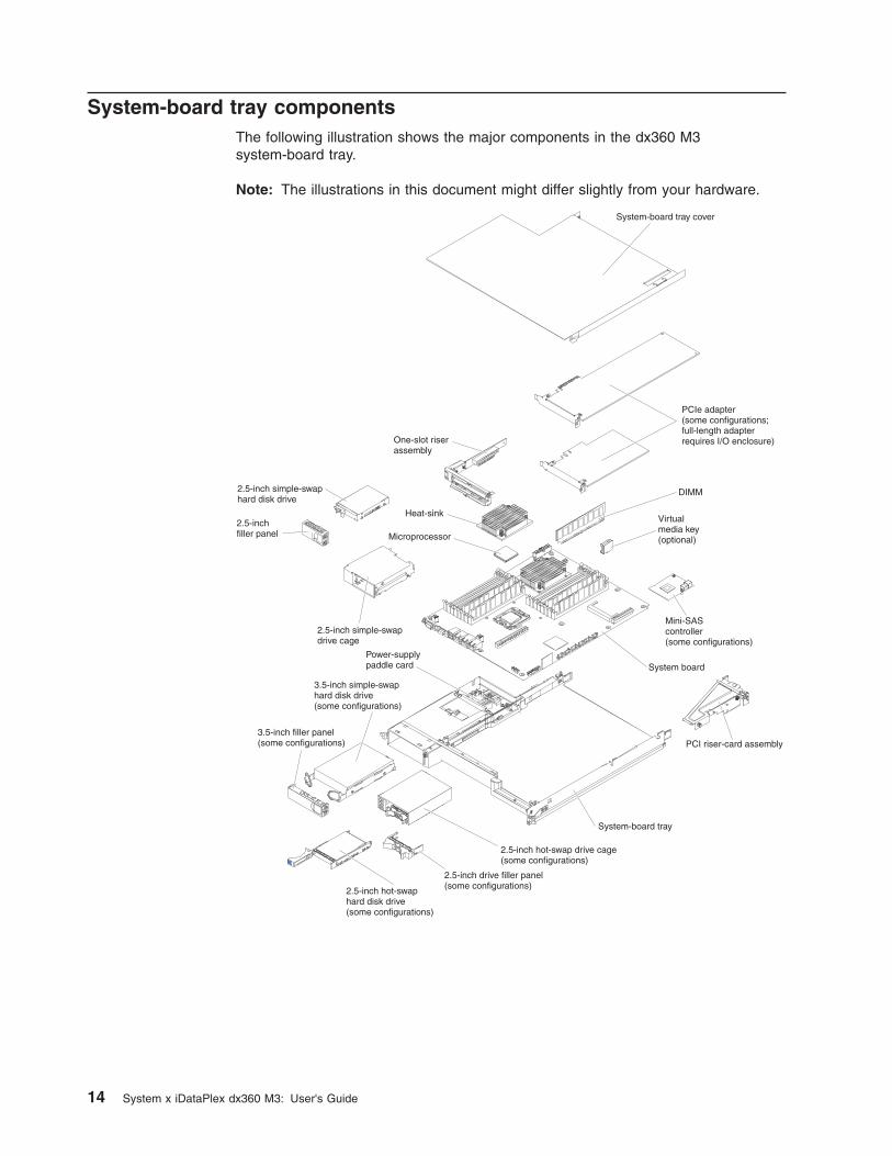
System-board tray componentsThe following illustration shows the major components in the dx360 M3system-board tray.
Note: The illustrations in this document might differ slightly from your hardware.
14 System x iDataPlex dx360 M3: User's Guide
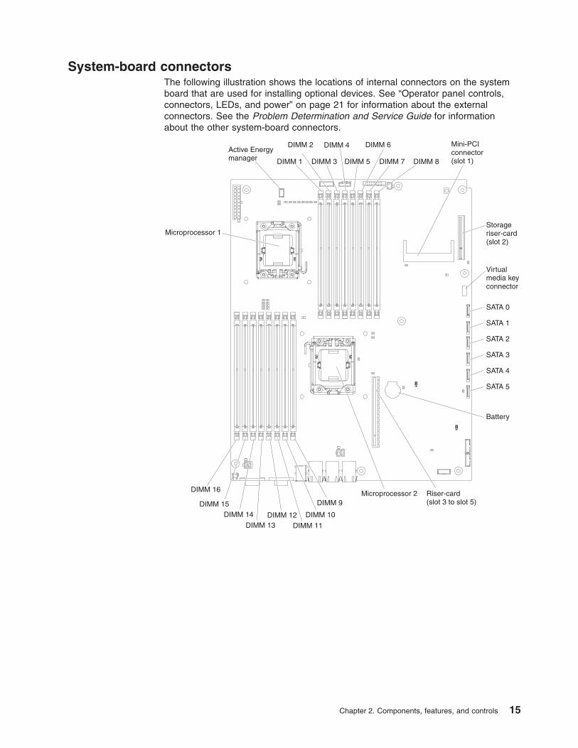
System-board connectorsThe following illustration shows the locations of internal connectors on the systemboard that are used for installing optional devices. See “Operator panel controls,connectors, LEDs, and power” on page 21 for information about the externalconnectors. See the Problem Determination and Service Guide for informationabout the other system-board connectors.
DIMM 1
DIMM 2
DIMM 3
DIMM 4
DIMM 5
DIMM 6
DIMM 7 DIMM 8
SATA 0
SATA 1
SATA 2
SATA 3
SATA 4
SATA 5
Battery
Storageriser-card(slot 2)
Riser-card(slot 3 to slot 5)
Microprocessor 2
Microprocessor 1
DIMM 9
DIMM 10
DIMM 11DIMM 12
DIMM 13
DIMM 14DIMM 15
DIMM 16
Virtualmedia keyconnector
Active Energymanager
Mini-PCIconnector(slot 1)
Chapter 2. Components, features, and controls 15
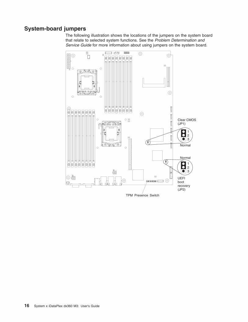
System-board jumpersThe following illustration shows the locations of the jumpers on the system boardthat relate to selected system functions. See the Problem Determination andService Guide for more information about using jumpers on the system board.
16 System x iDataPlex dx360 M3: User's Guide

Flexible chassis features
Note: The illustrations in this document might differ slightly from your hardware.
The following illustration shows a 2U chassis. The 2U chassis contains a powersupply and a fan assembly that provide operating power and cooling for allcomponents in the chassis. The 2U chassis can support two system-board trays orone system-board tray with an expansion enclosure.
Chapter 2. Components, features, and controls 17

The following illustration shows a 3U chassis. The 3U chassis contains a powersupply and a fan assembly that provide operating power and cooling for allcomponents in the chassis. Depending on your server configuration, it also providessupport for the installation of up to twelve 3.5-inch hot-swap SAS or SATA hard diskdrives (SAS and SATA hard disk drives cannot be used within the same server).The 3U chassis supports one system-board tray that must contain a RAID adapterto control operation of these hard disk drives.
18 System x iDataPlex dx360 M3: User's Guide

Hardware configuration examplesThe 2U chassis and 3U chassis support the following iDataPlex dx360 M3configurations:
v 2U compute server: a 2U chassis that contains two dx360 M3 system-board trays
v 2U input/output server: a 2U chassis that contains one dx360 M3 system-boardtray and an optional I/O enclosure
v 2U storage server: a 2U chassis that contains one dx360 M3 system-board trayand an optional storage enclosure
v 3U storage server: a 3U chassis that contains one dx360 M3 system-board trayand integrated storage
Note: The illustrations in this document might differ slightly from your hardware.
2U compute serverThe 2U compute server consists of two identical dx360 M3 system-board trays thatare installed in a 2U chassis. Each system-board tray has one PCI adapterconnector and one 3.5-inch hard disk drive bay that might be configured to hold two2.5-inch hard disk drives or solid-state drives. The following illustration shows aninstalled 3.5-inch simple-swap SATA hard disk drive.
Chapter 2. Components, features, and controls 19
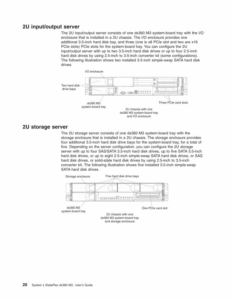
2U input/output serverThe 2U input/output server consists of one dx360 M3 system-board tray with the I/Oenclosure that is installed in a 2U chassis. The I/O enclosure provides oneadditional 3.5-inch hard disk bay, and three (one is x8 PCIe slot and two are x16PCIe slots) PCIe slots for the system-board tray. You can configure the 2Uinput/output server with up to two 3.5-inch hard disk drives or up to four 2.5-inchhard disk drives by using 2.5-inch to 3.5-inch converter kit (some configurations).The following illustration shows two installed 3.5-inch simple-swap SATA hard diskdrives.
2U storage serverThe 2U storage server consists of one dx360 M3 system-board tray with thestorage enclosure that is installed in a 2U chassis. The storage enclosure providesfour additional 3.5-inch hard disk drive bays for the system-board tray, for a total offive. Depending on the server configuration, you can configure the 2U storageserver with up to four SAS/SATA 3.5-inch hard disk drives, up to five SATA 3.5-inchhard disk drives, or up to eight 2.5-inch simple-swap SATA hard disk drives, or SAShard disk drives, or solid-state hard disk drives by using 2.5-inch to 3.5-inchconverter kit. The following illustration shows five installed 3.5-inch simple-swapSATA hard disk drives.
20 System x iDataPlex dx360 M3: User's Guide
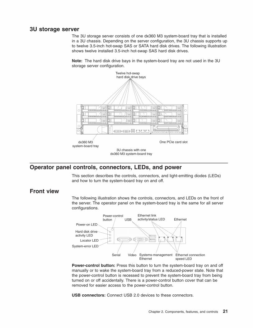
3U storage serverThe 3U storage server consists of one dx360 M3 system-board tray that is installedin a 3U chassis. Depending on the server configuration, the 3U chassis supports upto twelve 3.5-inch hot-swap SAS or SATA hard disk drives. The following illustrationshows twelve installed 3.5-inch hot-swap SAS hard disk drives.
Note: The hard disk drive bays in the system-board tray are not used in the 3Ustorage server configuration.
Operator panel controls, connectors, LEDs, and powerThis section describes the controls, connectors, and light-emitting diodes (LEDs)and how to turn the system-board tray on and off.
Front viewThe following illustration shows the controls, connectors, and LEDs on the front ofthe server. The operator panel on the system-board tray is the same for all serverconfigurations.
Power-control button: Press this button to turn the system-board tray on and offmanually or to wake the system-board tray from a reduced-power state. Note thatthe power-control button is recessed to prevent the system-board tray from beingturned on or off accidentally. There is a power-control button cover that can beremoved for easier access to the power-control button.
USB connectors: Connect USB 2.0 devices to these connectors.
Chapter 2. Components, features, and controls 21

Ethernet link activity/status LED: This LED is on each Ethernet connector. Whenthis LED is lit, it indicates that there is an active connection on the Ethernet port.When this LED is flashing, it indicates that there is activity between the server andthe network.
Ethernet connectors: Use these connectors to connect the server to a network.
Ethernet connection speed LED: This LED is on each Ethernet connector. Thestatus of this LED indicates the connection speed, in megabits-per-second (Mbps),between the server and the network as follows:
v LED off: 10 Mbps connection
v LED lit amber: 100 Mbps connection
v LED lit green: 1000 Mbps connection
Systems-management Ethernet connector: Use this connector to connect theserver to a network for systems-management information control.
Video connector: Connect a monitor to this connector.
Serial connector: Connect a 9-pin serial device to this connector. The serial port isshared with the integrated management module (IMM). The IMM can take control ofthe shared serial port to perform text console redirection and to redirect serialtraffic, using Serial over LAN (SOL).
System-error LED: When this LED is lit, it indicates that a system error hasoccurred. The source of the error is logged in the system-event log that is accessedin the Setup utility.
Locator LED: This LED can be lit remotely by the system administrator to aid invisually locating the system-board tray. In an IPMI environment, the systemadministrator can light the LED by using the IPMI chassis identify command.
Hard disk drive activity LED: When this LED is lit or flashing, it indicates that anassociated hard disk drive is in use.
In configurations that contain hot-swap hard disk drives, each hot-swap hard diskdrive has the following LEDs.
v Hot-swap hard disk drive activity LED: When this LED is flashing, it indicatesthat the drive is in use.
v Hot-swap hard disk drive status LED: When this LED is lit, it indicates that thedrive has failed.
Power-on LED: The states of the power-on LED are as follows:
v Off: AC power is not present, or the power supply or the LED itself has failed.
v Flashing rapidly (4 times per second): The system-board tray is turned off andis not ready to be turned on. The power-control button is disabled.
v Flashing slowly (once per second): The system-board tray is turned off and isready to be turned on. You can press the power-control button to turn on thesystem-board tray.
v Lit: The system-board tray is turned on.
v Fading on and off: The system-board tray is in a reduced-power state. To wakethe system-board tray, press the power-control button or use the IMM Webinterface.
22 System x iDataPlex dx360 M3: User's Guide

Note: If this LED is off, it does not mean that no electrical power is present. TheLED might be burned out. To remove all electrical power, you must remove thesystem-board tray from the chassis, remove the chassis from the rack, ordisconnect the power cord from the power source.
Rear viewThe following illustration shows the connector on the rear of the 2U chassis, the 3Uchassis is similar.
Power-cord connector: Connect the power cord to this connector. When thechassis is installed in an iDataPlex rack, it is automatically connected to powerthrough a power cord that is mounted to the rack rail.
Turning on the system-board trayAfter you install the system-board tray in a chassis, the system-board tray can startin any of the following ways.
Important: To avoid potential problems during startup, disconnect any USB flashdrives from the system that contain the Smart Launch Utility before you turn on thesystem-board tray.
v You can press the power-control button on the front of the system-board tray(see “Operator panel controls, connectors, LEDs, and power” on page 21) to startthe system-board tray.
v In an IPMI environment, the system administrator can turn on the system-boardtray by using the IPMI chassis control command.
v If a power failure occurs, the system-board tray can start automatically whenpower is restored, if it is configured to do so.
Turning off the system-board trayWhen you turn off the system-board tray, it is still connected to ac power throughthe chassis power supply. The system-board tray still can respond to requests fromthe IMM, such as a remote request to turn on the system-board tray. To remove allpower from the system-board tray, you must remove the tray from the chassis.
Shut down the operating system before you turn off the system-board tray. See theoperating-system documentation for information about shutting down the operatingsystem.
Chapter 2. Components, features, and controls 23
The system-board tray can be turned off in any of the following ways:
v You can press the power-control button on the front of the system-board tray(see “Operator panel controls, connectors, LEDs, and power” on page 21). Thisstarts an orderly shutdown of the operating system, if this feature is supported bythe operating system.
v You can turn off the system-board tray from the operating system, if the operatingsystem supports this feature. After an orderly shutdown of the operating system,the system-board tray will be turned off automatically.
v In an IPMI environment, the system administrator can turn off the system-boardtray by using the IPMI chassis control command.
v If the operating system stops functioning, you can press and hold thepower-control button for more than 4 seconds to turn off the system-board tray.
v You might be able to turn off the system-board tray by using an optionalmanagement appliance.
– If the system is not operating correctly, the management appliance mightautomatically turn off the system-board tray.
– Through the management appliance control interface, you might also be ableto configure the management appliance to turn off the system-board tray. Foradditional information, see the documentation for your management appliance.
24 System x iDataPlex dx360 M3: User's Guide

Chapter 3. Installing optional devices
This section provides detailed instructions for installing optional hardware devices.
In addition to the instructions in this chapter for installing optional hardware devices,updating firmware and device drivers, and completing the installation, IBM BusinessPartners must also complete the steps in “Instructions for IBM Business Partners.”
Important: To help ensure that the devices that you install work correctly and donot introduce problems, observe the following precautions:
1. Make sure that the server and the installed firmware levels support the devicesthat you are installing. If necessary, update the UEFI and IMM firmware and anyother firmware that is stored on the system boards. For information about wherefirmware is stored in the server, see Chapter 6, “Configuration information andinstructions,” in the Problem Determination and Service Guide. For a list ofsupported optional devices for the server, see http://www.ibm.com/systems/info/x86servers/serverproven/compat/us/.
2. Before you install optional hardware devices, make sure that the server isworking correctly. Start the server and make sure that the operating systemstarts, if an operating system is installed, or that a 19990305 error code isdisplayed, indicating that an operating system was not found but the server isotherwise working correctly. If the server is not working correctly, see theProblem Determination and Service Guide for information about how to rundiagnostics.
3. Follow the installation procedures in this chapter and use the correct tools.Incorrectly installed devices can cause system failures because of damagedpins in sockets or connectors, loose cabling, or loose components.
4. Use the best practices to apply current firmware and device-driver updates forthe server and optional devices. To download the IBM System x FirmwareUpdate Best Practices document, go to http://www.ibm.com/support/entry/portal/docdisplay?brand=50000020&lndocid=MIGR-5082923. Additional hints and tipsare available from the following sites:v IBM support: http://www.ibm.com/supportportal/v System x configuration tools: http://www.ibm.com/systems/x/hardware/
configtools.html
Instructions for IBM Business PartnersIn addition to the instructions in this chapter for installing optional hardware devices,updating firmware and device drivers, and completing the installation, IBM BusinessPartners must also complete the following steps:
1. Before you configure a server for a customer, complete the Solution Assurancechecklist at http://w3.ibm.com/support/assure/assur30i.nsf/webindex/sa294/.
2. After you have confirmed that the server starts correctly and recognizes thenewly installed devices and that no error LEDs are lit, run the Dynamic SystemAnalysis (DSA) stress tests. For information about using DSA, see the ProblemDetermination and Service Guide.
3. Shut down and restart the server multiple times to ensure that the server iscorrectly configured and functions correctly with the newly installed devices.
4. Save the DSA log as a file and send it to IBM.
5. To ship the server, repackage it in the original undamaged packing material andobserve IBM procedures for shipping.
© Copyright IBM Corp. 2011 25

Support information for IBM Business Partners is available at http://www.ibm.com/partnerworld/.
Installation guidelines
Attention:
v Static electricity that is released to internal server components when the server ispowered-on might cause the system to halt, which might result in the loss ofdata. To avoid this potential problem, always use an electrostatic-discharge wriststrap or other grounding system when removing or installing a hot-swap device.
v This product is not intended to be connected directly or indirectly by any meanswhatsoever to interfaces of public telecommunications networks, neither to beused in Public Services Network.
Before you install optional devices, read the following information:
v Read the safety information that begins on page vii and “Handling static-sensitivedevices” on page 27. This information will help you work safely.
v Before you install optional hardware devices, make sure that the server isworking correctly. Start the server, and make sure that the operating systemstarts, if an operating system is installed, or that an error message is displayed,indicating that an operating system was not found but the server is otherwiseworking correctly. If the server is not working correctly, see the ProblemDetermination and Service Guide for diagnostic information.
v Observe good housekeeping in the area where you are working. Place removedcovers and other parts in a safe place.
v Do not attempt to lift an object that you think is too heavy for you. If you have tolift a heavy object, observe the following precautions:
– Make sure that you can stand safely without slipping.
– Distribute the weight of the object equally between your feet.
– Use a slow lifting force. Never move suddenly or twist when you lift a heavyobject.
– To avoid straining the muscles in your back, lift by standing or by pushing upwith your leg muscles.
v Back up all important data before you make changes to disk drives.
v Have a small flat-blade screwdriver and a small Phillips screwdriver available.
v You do not have to turn off the system-board tray to install or replace hot-swapdrives or hot-plug Universal Serial Bus (USB) devices. However, you must shutdown the operating system and turn off the system-board tray before you removethe system-board tray from a chassis or before you install simple-swap hard diskdrives.
v Blue on a component indicates touch points, where you can grip the componentto remove or install it, open or close a latch, and so on.
v Orange on a component or an orange label on or near a component indicatesthat the component can be hot-swapped, which means that if the server andoperating system support hot-swap capability, you can remove or install thecomponent while the server is running. (Orange can also indicate touch points onhot-swap components.) See the instructions for removing or installing a specifichot-swap component for any additional procedures that you might have toperform before you remove or install the component.
26 System x iDataPlex dx360 M3: User's Guide
System reliability guidelinesTo help ensure proper cooling and system reliability, make sure that the followingrequirements are met:
v Each of the drive bays has a drive or a filler panel and electromagneticcompatibility (EMC) shield installed in it.
v You have followed the cabling instructions that come with optional adapters.
v You have replaced a hot-swap drive within 2 minutes of removal.
v The system-board tray battery is operational. If the battery becomes defective,replace it immediately.
v Microprocessor socket 2 always contains either a microprocessor baffle or amicroprocessor and heat sink.
v You have replaced one or both system-board trays within 2 minutes of removal.
v For a 2U compute server, do not operate the upper system-board tray with thelower system-board tray removed or powered off, except for servicing.
Handling static-sensitive devices
Attention: Static electricity can damage the server and other electronic devices.To avoid damage, keep static-sensitive devices in their static-protective packagesuntil you are ready to install them.
To reduce the possibility of damage from electrostatic discharge, observe thefollowing precautions:
v Limit your movement. Movement can cause static electricity to build up aroundyou.
v The use of a grounding system is recommended. For example, wear anelectrostatic-discharge wrist strap, if one is available.
v Handle the device carefully, holding it by its edges or its frame.
v Do not touch solder joints, pins, or exposed circuitry.
v Do not leave the device where others can handle and damage it.
v While the device is still in its static-protective package, touch it to an unpaintedmetal surface on the outside of the rack, chassis, or system-board tray for atleast 2 seconds. This drains static electricity from the package and from yourbody.
v Remove the device from its package and install it directly into the system-boardtray or enclosure without setting down the device. If it is necessary to set downthe device, put it back into its static-protective package. Do not place the deviceon the system-board tray cover or on a metal surface.
v Take additional care when you handle devices during cold weather. Heatingreduces indoor humidity and increases static electricity.
Chapter 3. Installing optional devices 27

Removing a 3U chassis from an iDataPlex rack
To remove a 3U chassis from an iDataPlex rack, complete the following steps:
1. Read the safety information that begins on page vii and “Installation guidelines”on page 26.
2. Turn off the server and all attached devices (see “Turning off the system-boardtray” on page 23).
3. If external cables are connected to the front of the system-board tray, notewhere they are connected; then, remove them.
Attention: When you use RAID arrays, hard disk drives must be installed inthe same location from which they were removed.
4. Note where the hard disk drives are installed; then, remove them (see“Removing a hard disk drive” on page 33).
Statement 4:
≥ 18 kg (39.7 lb) ≥ 32 kg (70.5 lb) ≥ 55 kg (121.2 lb)
CAUTION:Use safe practices when lifting.
5. Remove the 2 screws and slide the 3U chassis from the iDataPlex rack.
6. Set the 3U chassis on a flat, static-protective surface.
28 System x iDataPlex dx360 M3: User's Guide

Removing a system-board tray from a 2U chassisNotes:
1. If two system-board trays are installed in the chassis, they can be removedindependently of each other.
2. If an expansion enclosure is installed on the system-board tray, you will removethe expansion enclosure and the system-board tray from the chassis as oneassembly.
To remove a system-board tray from a 2U chassis, complete the following steps:
1. Read the safety information that begins on page vii and “Installation guidelines”on page 26.
2. Turn off the system-board tray and all attached devices (see “Turning off thesystem-board tray” on page 23).
3. If external cables are connected to the front of the system-board tray orexpansion enclosure, note where they are connected; then, remove them.
4. Press in on the two release handles, pull the system-board tray and expansionenclosure, if one is attached, out of the 2U chassis, and set it on a flat,static-protective surface.
Chapter 3. Installing optional devices 29
Removing a system-board tray from a 3U chassis
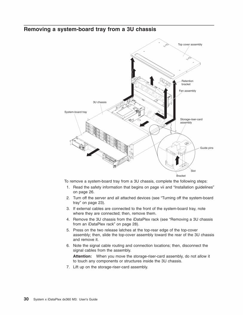
To remove a system-board tray from a 3U chassis, complete the following steps:
1. Read the safety information that begins on page vii and “Installation guidelines”on page 26.
2. Turn off the server and all attached devices (see “Turning off the system-boardtray” on page 23).
3. If external cables are connected to the front of the system-board tray, notewhere they are connected; then, remove them.
4. Remove the 3U chassis from the iDataPlex rack (see “Removing a 3U chassisfrom an iDataPlex rack” on page 28).
5. Press on the two release latches at the top-rear edge of the top-coverassembly; then, slide the top-cover assembly toward the rear of the 3U chassisand remove it.
6. Note the signal cable routing and connection locations; then, disconnect thesignal cables from the assembly.
Attention: When you move the storage-riser-card assembly, do not allow itto touch any components or structures inside the 3U chassis.
7. Lift up on the storage-riser-card assembly.
30 System x iDataPlex dx360 M3: User's Guide

8. Turn the storage-riser-card assembly to access the ServeRAID SAS controller.
9. Pull the controller from the connector on the storage-riser-card assembly.
10. Disconnect the battery cable from the battery cable interposer card.
11. Remove the storage-riser-card assembly and ServeRAID SAS controller fromthe 3U chassis.
12. Slide and release the retention bracket that secures the fan assembly, andremove the bracket from the chassis.
13. Lift up on both fan-assembly handles and remove the fans from the 3Uchassis.
14. Note the cable routing and connection locations; then, disconnect the cablesthat connect the system-board tray to the 3U chassis.
15. Push on the back edge of the system-board tray from inside the 3U chassisand slide the system-board tray forward.
16. Pull the system-board tray out of the 3U chassis and set it on a flat,static-protective surface.
Removing the system-board tray cover
Note: If an expansion enclosure is installed on the system-board tray, remove itinstead (see “Removing an expansion enclosure” on page 32).
Releaselatch
System-boardtray cover
System-boardtray
Chapter 3. Installing optional devices 31

To remove the system-board tray cover, complete the following steps:
1. Read the safety information that begins on page vii and “Installation guidelines”on page 26.
2. Turn off the system-board tray and all attached devices (see “Turning off thesystem-board tray” on page 23).
3. If the system-board tray is installed in a chassis, remove it (see “Removing asystem-board tray from a 2U chassis” on page 29 or “Removing a system-boardtray from a 3U chassis” on page 30).
4. Carefully set the system-board tray on a flat, static-protective surface, with thecover side up.
5. Pull the cover release on each side of the system-board tray outward; then, liftthe cover open.
6. Lift the cover off the system-board tray and store it for future use.
Note: If two system-board trays are installed in a 2U chassis, covers must beinstalled on both of them.
Removing an expansion enclosure
Releaselatch
Expansionenclosure
System-boardtray
To remove an expansion enclosure, complete the following steps:
1. Read the safety information that begins on page vii and “Installation guidelines”on page 26.
2. Turn off the system-board tray and all attached devices (see “Turning off thesystem-board tray” on page 23).
3. If the system-board tray is installed in a chassis, remove it (see “Removing asystem-board tray from a 2U chassis” on page 29.
4. Carefully set the system-board tray on a flat, static-protective surface.
5. If you are removing the enclosure, note the cable routing and connectionlocations; then, disconnect the cables that connect the expansion enclosure tothe system-board tray.
6. Pull the expansion-unit release on each side of the system-board tray outward;then, rotate the expansion enclosure open.
32 System x iDataPlex dx360 M3: User's Guide

7. Using care not to pull on the cables, lift the expansion enclosure from thesystem-board tray and carefully set it upside down behind the system-board trayon a flat, static-protective surface.
Removing a hard disk driveThe dx360 M3 server configurations support installation of four hard disk drivetypes. The following sections describe the removal of each type of hard disk drive.
Removing a 3.5-inch hot-swap hard disk drive
Note: The following illustration shows how to remove a 3.5-inch hot-swap hard diskdrive from a 3U chassis.
3U chassis
Note: You do not have to turn off the server to remove a hot-swap drive.
To remove a hot-swap hard disk drive, complete the following steps:
1. Read the safety information that begins on page vii and “Installation guidelines”on page 26.
2. Rotate the drive tray handle to the open position.
3. Grasp the handle; then, pull the drive out of the drive bay.
Note: A hard disk drive or filler panel must always be installed in each drivebay when the server is turned on.
4. Store the drive for later use.
Note: If you install or remove a hard disk drive, see the documentation thatcomes with your RAID adapter for information about reconfiguring the diskarrays.
Removing a 3.5-inch simple-swap hard disk drive
Note: The following illustration shows how to remove a 3.5-inch simple-swap harddisk drive from a 2U chassis.
Chapter 3. Installing optional devices 33

To remove a simple-swap hard disk drive, complete the following steps:
1. Read the safety information that begins on page vii and “Installation guidelines”on page 26.
2. Turn off the system-board tray and all attached devices (see “Turning off thesystem-board tray” on page 23).
3. Remove the filler panel from the bay that contains the simple-swap hard diskdrive.
4. Pull the loops of the drive toward each other; then, pull the drive out of the drivebay.
Note: A hard disk drive or filler panel must always be installed in each drivebay when the server is turned on. In each drive bay that contains a simple-swaphard disk drive, a filler panel must always be installed in addition to the drive.
5. Store the drive and filler panel for later use.
Removing a 2.5-inch hot-swap hard disk drive
Note: The following illustration shows how to remove a 2.5-inch hot-swap hard diskdrive from a 2U chassis.
Note: You do not have to turn off the server to remove a hot-swap drive.
34 System x iDataPlex dx360 M3: User's Guide

To remove a 2.5-inch hot-swap hard disk drive, complete the following steps:
1. Read the safety information that begins on page vii and “Installation guidelines”on page 26.
2. Rotate the drive tray handle to the open position.
3. Grasp the handle; then, pull the drive out of the drive bay.
Note: A hard disk drive or filler panel must always be installed in each drivebay when the server is turned on.
4. Store the drive for later use.
Note: If you install or remove a hard disk drive, see the documentation thatcomes with your RAID adapter for information about reconfiguring the diskarrays.
Removing a 2.5-inch simple-swap hard disk drive or solid-state drive
Note: The following illustration shows how to remove a 2.5-inch simple-swap harddisk drive or solid-state drive from a 2U chassis.
To remove a 2.5-inch simple-swap hard disk drive or solid-state drive, complete thefollowing steps:
1. Read the safety information that begins on page vii and “Installation guidelines”on page 26.
2. Turn off the system-board tray and all attached devices (see “Turning off thesystem-board tray” on page 23).
3. Remove the filler panel from the bay that contains the simple-swap hard diskdrive.
4. Slide the retention tab; then, pull the drive out of the drive bay.
Note: A drive or filler panel must always be installed in each drive bay whenthe server is turned on. In each drive bay that contains a simple-swap hard diskdrive or solid-state drive, a filler panel must always be installed in addition to thedrive.
5. Store the drive for later use.
Installing an adapterThe following notes describe the types of adapters that the server supports andother information that you must consider when you install an adapter:
Chapter 3. Installing optional devices 35
v To ensure that an adapter works correctly in your UEFI-based server, make surethat the adapter firmware is at the latest level.
Important: Some cluster solutions require specific code levels or coordinatedcode updates. If the device is part of a cluster solution, verify that the latest levelof code is supported for the cluster solution before you update the code.
v Locate the documentation that comes with the adapter and follow thoseinstructions in addition to the instructions in this section. If you have to changeswitch settings or jumper settings on the adapter, follow the instructions thatcome with the adapter.
v Read the documentation that comes with your operating system.
v The server supports the following riser cards for optional adapters:
– One-slot riser card: PCIe x16 (x16) adapters
– Three-slot riser card: one PCIe x8 (x8) adapters with two PCIe x16 (x16)adapters
v Do not install the NVIDIA Grid Kx/Mxx, the NVIDIA Quadro Kxxxx or the NVIDIATesla Kxx adapter options in systems containing 1 TB of system memory ormore. If these options are installed in systems with 1 TB of memory or more, itmight cause undetected data corruption and system instability. These options areonly supported in systems containing less than 1 TB of memory. For moreinformation, see RETAIN tip H213010 at http://www.ibm.com/support/entry/myportal/docdisplay?lndocid=migr-5096047.
v In configurations that have a three-slot, the server scans the PCIe adapters toassign system resources, following the boot sequence that is set in the Setuputility.
Important: The maximum power consumption from all supply voltages for asingle PCIe slot is the same as specified in PCI Local Bus Specification Revision2.3 for conventional slots.
Note: All Graphics Processing Unit (GPU) adapters installed in the server mustbe the same. They must be identical in brand and type. When you installadditional GPUs, make sure you purchase GPUs with the same product partnumber as shown on the existing GPUs in the server.
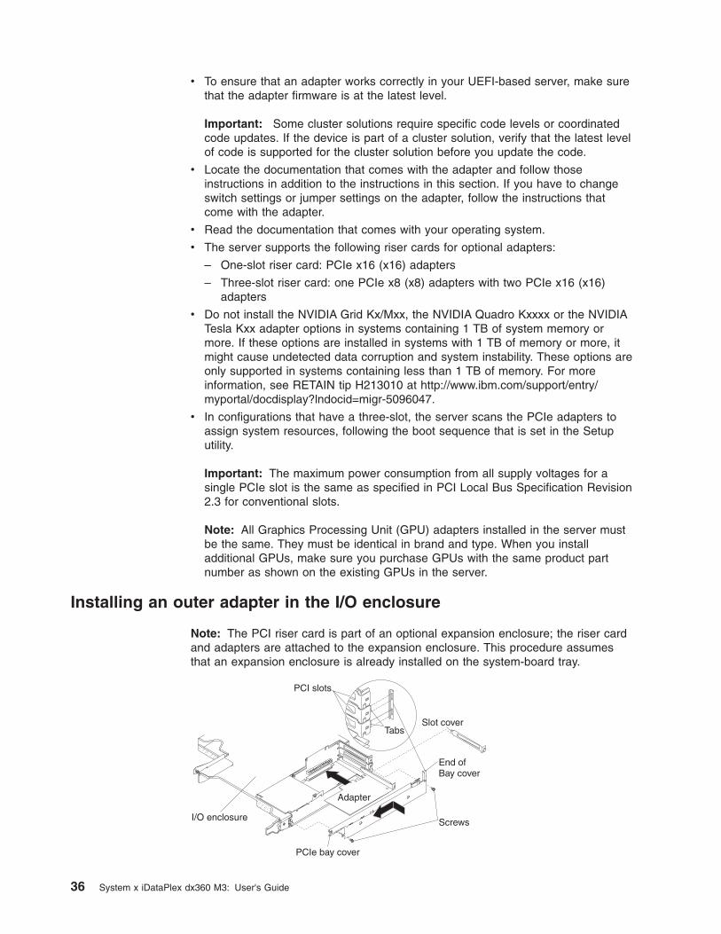
Installing an outer adapter in the I/O enclosure
Note: The PCI riser card is part of an optional expansion enclosure; the riser cardand adapters are attached to the expansion enclosure. This procedure assumesthat an expansion enclosure is already installed on the system-board tray.
Screws
Slot cover
PCI slots
Tabs
Adapter
End ofBay cover
PCIe bay cover
I/O enclosure
36 System x iDataPlex dx360 M3: User's Guide

To install an outer adapter in a PCI riser card, complete the following steps:
1. Read the safety information that begins on page vii and “Installation guidelines”on page 26.
2. Turn off the system-board tray and all attached devices (see “Turning off thesystem-board tray” on page 23).
3. If the system-board tray is installed in a chassis, remove it (see “Removing asystem-board tray from a 2U chassis” on page 29).
4. Remove the expansion enclosure (see “Removing an expansion enclosure” onpage 32) and set it upside down on a flat, static-protective surface.
Note: If an adapter is already installed in the riser card, the riser card andadapter are removed together.
5. Remove the screws, slide the PCIe adapter bay cover toward the front of theexpansion enclosure, and remove it. Save the screws and the PCIe adapterbay cover for later use.
6. If an adapter is installed in the connector on the riser card where you areinstalling the new adapter, remove it.
7. Touch the static-protective package that contains the adapter that you areinstalling to any unpainted metal surface on the chassis or rack; then, removethe adapter from the static-protective package. Avoid touching the componentsand gold-edge connectors on the adapter.
8. If you are installing a full-length adapter, remove the blue adapter guide (if any)from the end of the adapter.
Adapter guide
9. Follow the instructions that come with the adapter to set any jumpers orswitches.
10. Carefully grasp the adapter by the top edge or upper corner, and slide ithalfway into PCIe bay.
Note: If the adapter is a full-length adapter, or with a full-length extender,make sure it is seated in the groove of retainer bracket.
Chapter 3. Installing optional devices 37
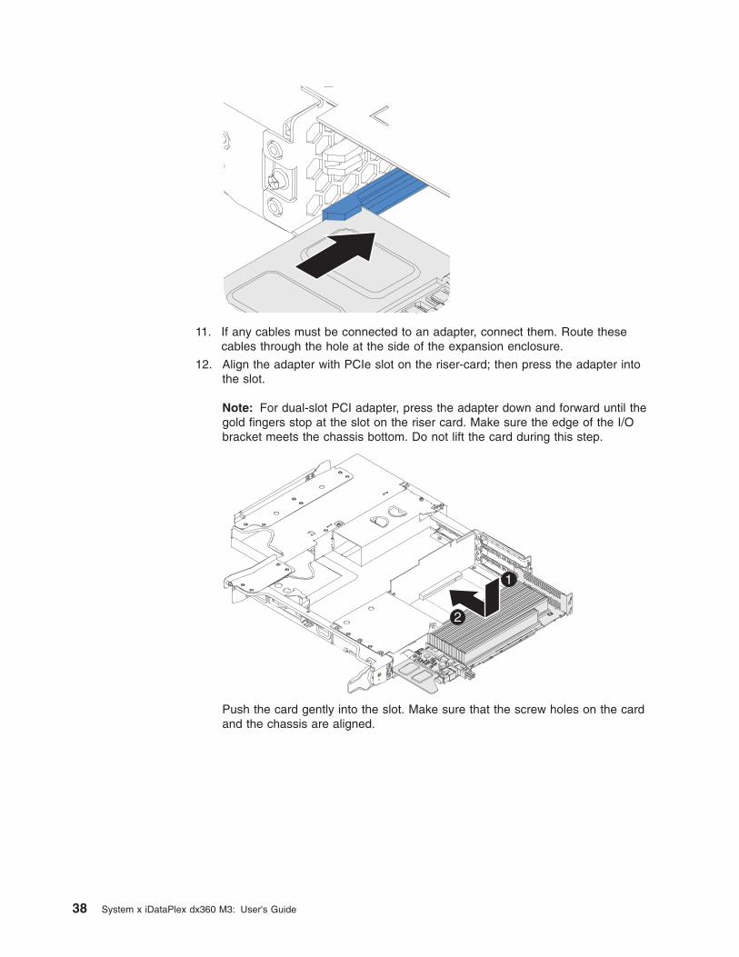
11. If any cables must be connected to an adapter, connect them. Route thesecables through the hole at the side of the expansion enclosure.
12. Align the adapter with PCIe slot on the riser-card; then press the adapter intothe slot.
Note: For dual-slot PCI adapter, press the adapter down and forward until thegold fingers stop at the slot on the riser card. Make sure the edge of the I/Obracket meets the chassis bottom. Do not lift the card during this step.
1
2
Push the card gently into the slot. Make sure that the screw holes on the cardand the chassis are aligned.
38 System x iDataPlex dx360 M3: User's Guide

13. If you have another adapter to install, do so now. Otherwise, continue with step11 on page 38.
14. Align the tabs on the PCIe adapter bay cover with the holes on the expansionenclosure; then, slide the PCIe adapter bay cover toward the rear of theexpansion enclosure until it stops.
15. Install the PCIe adapter bay cover screws.
Screws
PCIe bay cover
If you have other devices to install or remove, do so now. Otherwise, go to“Completing the installation” on page 53.
Chapter 3. Installing optional devices 39
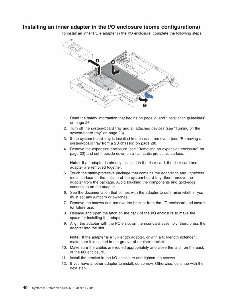
Installing an inner adapter in the I/O enclosure (some configurations)To install an inner PCIe adapter in the I/O enclosure, complete the following steps.
1. Read the safety information that begins on page vii and “Installation guidelines”on page 26.
2. Turn off the system-board tray and all attached devices (see “Turning off thesystem-board tray” on page 23).
3. If the system-board tray is installed in a chassis, remove it (see “Removing asystem-board tray from a 2U chassis” on page 29).
4. Remove the expansion enclosure (see “Removing an expansion enclosure” onpage 32) and set it upside down on a flat, static-protective surface.
Note: If an adapter is already installed in the riser card, the riser card andadapter are removed together.
5. Touch the static-protective package that contains the adapter to any unpaintedmetal surface on the outside of the system-board tray; then, remove theadapter from the package. Avoid touching the components and gold-edgeconnectors on the adapter.
6. See the documentation that comes with the adapter to determine whether youmust set any jumpers or switches.
7. Remove the screws and remove the bracket from the I/O enclosure and save itfor future use.
8. Release and open the latch on the back of the I/O enclosure to make thespace for installing the adapter.
9. Align the adapter with the PCIe slot on the riser-card assembly; then, press theadapter into the slot.
Note: If the adapter is a full-length adapter, or with a full-length extender,make sure it is seated in the groove of retainer bracket.
10. Make sure the cables are routed appropriately and close the latch on the backof the I/O enclosure.
11. Install the bracket in the I/O enclosure and tighten the screws.
12. If you have another adapter to install, do so now. Otherwise, continue with thenext step.
40 System x iDataPlex dx360 M3: User's Guide

Note: To complete the installation of the PCIe adapter, see the documentationthat comes with the adapter for device-driver and configuration information.
13. If any cables must be connected to an adapter, connect them. Route thesecables through the hole at the side of the expansion enclosure.
14. Align the tabs on the PCIe adapter bay cover with the holes on the expansionenclosure; then, slide the PCIe adapter bay cover toward the rear of theexpansion enclosure until it stops.
15. Install the PCIe adapter bay cover screws.
If you have other devices to install or remove, do so now. Otherwise, go to“Completing the installation” on page 53.
Installing an adapter to a front PCI riser-card assembly
Note: The front PCI riser-card assembly supports installation of only half-length,full-height adapters.
To install an adapter to a front PCI riser-card assembly, complete the followingsteps:
1. Read the safety information that begins on page vii and “Installation guidelines”on page 26.
2. Turn off the system-board tray and all attached devices (see “Turning off thesystem-board tray” on page 23).
3. If the system-board tray is installed in a chassis, remove it (see “Removing asystem-board tray from a 2U chassis” on page 29 or “Removing asystem-board tray from a 3U chassis” on page 30).
4. If an expansion enclosure is installed on the system-board tray, remove it (see“Removing an expansion enclosure” on page 32); otherwise, remove thesystem-board tray cover (see “Removing the system-board tray cover” on page31).
5. Remove the riser-card retaining screw on the front of the chassis. Store thescrew for future use.
Chapter 3. Installing optional devices 41

Note: If an adapter is already installed in the riser card, the riser card andadapter are removed together.
6. Carefully grasp the front PCI riser-card assembly by its top edge or uppercorners, and pull the riser card straight up and out of the system board.
7. Carefully set the riser card on a flat, static-protective surface. If an adapter isinstalled in the riser card, remove it.
8. Touch the static-protective package that contains the adapter that you areinstalling to any unpainted metal surface on the chassis or rack; then, removethe adapter from the static-protective package. Avoid touching the componentsand gold-edge connectors on the adapter.
9. Follow the instructions that come with the adapter to set any jumpers orswitches.
10. Carefully grasp the adapter by the top edge or upper corner and insert it in thefront PCI riser-card assembly. Align the adapter with the connector on the risercard; then, press the adapter firmly into the connector.
Notes:
a. Ensure that the tab on the riser-card bracket is properly aligned with theslot on the adapter bracket.
b. If the PCI riser card has only 1 slot, then the PCIe adapter is aligned withslot 3. If the PCI riser card has 3 slots, then the PCIe adapters are alignedwith slot 3, slot 4, and slot 5 respectively.
PCI slot 5
PCI slot 3
PCI slot 4
PCI slot 5
PCI slot 3PCI slot 4
c. Make sure that the adapter is inserted carefully. Improper installation of anadapter might damage the PCIe riser-card assembly or the adapter.
11. Follow the cabling instructions, if any, that come with the adapter. If possible,route the adapter cables before you install the adapter.
42 System x iDataPlex dx360 M3: User's Guide

12. Pinch the two sides of the front PCI riser-card assembly, and align the risercard with the riser-card connector on the system board; then, press the risercard firmly, evenly with both hands, into the connector.
13. Install the riser-card retaining screw at the front of the chassis.
If you have other devices to install or remove, do so now. Otherwise, go to“Completing the installation” on page 53.
Installing a ServeRAID-M1015 to a rear storage PCI riser-cardassembly
This topic describes installing an adapter in a PCI expansion slot to a rear storagePCI riser-card assembly.
To ensure that a ServeRAID adapter works correctly in your server, make sure thatthe adapter firmware is at the latest level.
To install an adapter, complete the following steps.
1. Read the safety information that begins on page vii and “Installation guidelines”on page 26.
2. Turn off the system-board tray and all attached devices (see “Turning off thesystem-board tray” on page 23).
3. If the system-board tray is installed in a chassis, remove it (see “Removing asystem-board tray from a 2U chassis” on page 29 or “Removing a system-boardtray from a 3U chassis” on page 30).
4. If an expansion enclosure is installed on the system-board tray, remove it (see“Removing an expansion enclosure” on page 32); otherwise, remove thesystem-board tray cover (see “Removing the system-board tray cover” on page31).
5. Align the adapter with the PCI connector on the riser card and the guide on theexternal end of the riser-card assembly. Press the adapter firmly into the PCIconnector on the riser card.
6. Connect any required cables to the adapter.
Chapter 3. Installing optional devices 43

Attention:
v When you route cables, do not block any connectors or the ventilated spacearound any of the fans.
v Make sure that cables are not routed on top of components under the PCIriser-card assembly.
v Make sure that cables are not pinched by the server components.
7. Install the PCI riser-card assembly that contains the adapter (see “Installing arear PCIe riser-card assembly in the system-board tray”).
8. Perform any configuration tasks that are required for the adapter.
9. Reconnect the external cables; then, reconnect the power cords and turn on theperipheral devices and the server.
Installing a rear PCIe riser-card assembly in the system-board tray
Note: You can only install a ServeRAID-M1015 controller in the rear PCIeriser-card assembly.
To install a rear riser-card assembly, complete the following steps.
1. Read the safety information that begins on page vii and “Installation guidelines”on page 26.
2. Turn off the system-board tray and all attached devices (see “Turning off thesystem-board tray” on page 23).
3. If the system-board tray is installed in a chassis, remove it (see “Removing asystem-board tray from a 2U chassis” on page 29 or “Removing a system-boardtray from a 3U chassis” on page 30).
4. If an expansion enclosure is installed on the system-board tray, remove it (see“Removing an expansion enclosure” on page 32); otherwise, remove thesystem-board tray cover (see “Removing the system-board tray cover” on page31).
5. Reinstall any adapters and reconnect any internal cables you might haveremoved in other procedures.
6. Align the knobs of the PCI riser-card assembly with the PCI connector. Slide inand press down into the system board.
44 System x iDataPlex dx360 M3: User's Guide

7. Press down on the assembly. Make sure that the riser-card assembly is fullyseated in the riser-card connector on the system board.
Installing a hard disk driveThe dx360 M3 server configurations support installation of four hard disk drivetypes. The following sections describe the installation of each type of hard diskdrive.
Installing a 3.5-inch hot-swap hard disk drive
Note: The following illustration shows how to install a 3.5-inch hot-swap hard diskdrive in a 3U chassis.
3U chassis
To install a hot-swap hard disk drive, complete the following steps:
1. Read the safety information that begins on page vii and “Installation guidelines”on page 26.
2. Touch the static-protective package that contains the hard disk drive to anyunpainted metal surface on the chassis or rack; then, remove the hard diskdrive from the package.
Attention: Do not press on the top of the drive. Pressing the top mightdamage the drive.
3. Make sure that the drive tray handle is in the open position.
4. Align the drive with the guide rails in the drive bay; then, carefully slide the driveinto the bay until the drive stops.
5. Rotate the drive tray handle to the closed position.
Note: If you install or remove a hard disk drive, see the documentation that comeswith your RAID adapter for information about reconfiguring the disk arrays.
Installing a 3.5-inch simple-swap hard disk driveNotes:
1. Depending on your server configuration, you can install either 3.5-inch SASsimple-swap hard disk drives or 3.5-inch SATA simple-swap hard disk drives.You cannot use SAS simple-swap hard disk drives and SATA simple-swap harddisk drives in the same server.
Chapter 3. Installing optional devices 45

2. The following illustration shows how to install a 3.5-inch simple-swap hard diskdrive in a 2U chassis.
To install a simple-swap hard disk drive, complete the following steps:
1. Read the safety information that begins on page vii and “Installation guidelines”on page 26.
2. Turn off the server and all attached devices (see “Turning off the system-boardtray” on page 23).
3. Remove the filler panel from the simple-swap hard disk drive bay.
4. Touch the static-protective package that contains the hard disk drive to anyunpainted metal surface on the chassis or rack; then, remove the hard diskdrive from the package.
Attention: Do not press on the top of the drive. Pressing the top mightdamage the drive.
5. Align the drive with the guide rails in the drive bay.
6. Pull the loops of the drive toward each other; then, carefully slide the drive intothe bay until it stops, and release the loops.
Note: Do not release the loops on the drive until it is completely seated.
7. Install the filler panel in the simple-swap hard disk drive bay.
If you have other devices to install or remove, do so now. Otherwise, turn on thesystem-board tray (see “Turning on the system-board tray” on page 23).
Note: If the server has a PCIe RAID adapter and you install or remove a hard diskdrive, see the documentation that comes with your RAID adapter for informationabout reconfiguring the disk arrays.
Installing a 2.5-inch hot-swap hard disk driveNotes:
1. The 2.5-inch hot-swap hard disk drives can be installed only in systemconfigurations that support this drive type.
2. The following illustration shows how to install a 2.5-inch hot-swap hard diskdrive in a 2U chassis.
46 System x iDataPlex dx360 M3: User's Guide

To install a 2.5-inch hot swap hard disk drive, complete the following steps:
1. Read the safety information that begins on page vii and “Installation guidelines”on page 26.
2. Touch the static-protective package that contains the hard disk drive to anyunpainted metal surface on the chassis or rack; then, remove the hard diskdrive from the package.
Attention: Do not press on the top of the drive. Pressing the top mightdamage the drive.
3. Make sure that the drive tray handle is in the open position.
4. Align the drive with the guide rails in the drive bay; then, carefully slide the driveinto the bay until the drive stops.
5. Rotate the drive tray handle to the closed position.
Note: If you install or remove a hard disk drive, see the documentation that comeswith your RAID adapter for information about reconfiguring the disk arrays.
Installing a 2.5-inch simple-swap hard disk drive or solid-state driveNotes:
1. The 2.5-inch simple-swap hard disk drives or solid-state drives can be installedonly in system configurations that support this drive type.
2. The following illustration shows how to install a 2.5-inch simple-swap hard diskdrive or solid-state drive in a 2U chassis.
Chapter 3. Installing optional devices 47

To install a 2.5–inch simple-swap hard disk drive or solid-state drive, complete thefollowing steps:
1. Read the safety information that begins on page vii and “Installation guidelines”on page 26.
2. Turn off the server and all attached devices (see “Turning off the system-boardtray” on page 23).
3. Remove the filler panel from the simple-swap hard disk drive bay.
4. Touch the static-protective package that contains the hard disk drive orsolid-state drive to any unpainted metal surface on the chassis or rack; then,remove the drive from the package.
Attention: Do not press on the top of the drive. Pressing the top mightdamage the drive.
5. Align the drive with the guide rails in the drive bay.
6. Slide the retention tab; then, carefully slide the drive into the bay until it stops,and release the retention tab.
7. Install the filler panel in the simple-swap hard disk drive bay.
If you have other devices to install or remove, do so now. Otherwise, turn on thesystem-board tray (see “Turning on the system-board tray” on page 23).
Note: If the server has a PCIe RAID adapter and you install or remove a hard diskdrive, see the documentation that comes with your RAID adapter for informationabout reconfiguring the disk arrays.
Installing a memory moduleThe following notes describe the types of dual inline memory modules (DIMMs) thatthe system-board tray supports and other information that you must consider whenyou install DIMMs:
v The system-board tray supports only industry-standard double-data-rate 3(DDR3), -800, -1066, or -1333 MHz, PC3-10600R-999, registered, synchronousdynamic random-access memory (SDRAM) dual inline memory modules (DIMMs)with error correcting code (ECC).
v The system-board tray supports up to 16 DIMMs.
v The system-board tray supports three single-rank or dual-rank DIMMs perchannel. Table 1 shows an example of the maximum amount of memory that youcan install.
Table 1. Maximum memory installation
DIMM typeMaximum numberof DIMMs DIMM size Total memory
Single-rank/dual-rank 16 2 GB 32 GB
Dual-rank 16 4 GB 64 GB
Dual-rank 16 8 GB 128 GB
Quad-rank 12 16 GB 192 GB
v Table 2 on page 49 lists the DIMM connectors on each memory channel.
48 System x iDataPlex dx360 M3: User's Guide

Table 2. Connectors on each memory channel
Memory channelMicroprocessor 1 DIMMconnectors
Microprocessor 2 DIMMconnectors
Channel 0 1, 2, and 3 9, 10, and 11
Channel 1 4, 5, and 6 12, 13, and 14
Channel 2 7 and 8 15 and 16
v The DIMM options that are available are 2 GB, 4 GB, and 8 GB. Thesystem-board tray supports a minimum of 2 GB and a maximum of 128 GB ofsystem memory.
Note: The amount of usable memory will be reduced depending on the systemconfiguration. A certain amount of memory must be reserved for systemresources. To view the total amount of installed memory and the amount ofconfigured memory, run the Setup utility. For additional information, see “Usingthe Setup utility” on page 62.
v A minimum of two DIMMs must be installed for each microprocessor. However, toimprove system performance, install a minimum of three DIMMs for eachinstalled microprocessor.
v The maximum operating speed of the system-board tray is determined by theslowest DIMM, the number of DIMMs on each channel, and the combination ofDIMM rank and speed.
v The system-board tray comes with a minimum of two 2 GB DIMMs, installed inslots 3 and 6. When you install additional DIMMs, install the DIMMs in the ordershown in Table 3 to optimize system performance. All three channels on thememory interface for each microprocessor can be populated in any order andhave no matching requirements.
Table 3. Non-mirroring (normal) mode DIMM installation sequence
Microprocessors installed DIMM connector
1 3, 6, 8, 2, 5, 7, 1, then 4
2 3, 11, 6, 14, 8, 16, 2, 10, 5, 13, 7, 15, 1, 9, 4, then 12
v The following illustration shows the DIMM connectors on the system board.
Chapter 3. Installing optional devices 49

DIMM 1
DIMM 2
DIMM 3
DIMM 4
DIMM 5
DIMM 6
DIMM 7 DIMM 8
DIMM 9
DIMM 10
DIMM 11DIMM 12
DIMM 13
DIMM 14DIMM 15
DIMM 16
v Memory-mirroring mode replicates and stores data on two pairs of DIMMs withintwo channels simultaneously. If a failure occurs, the memory controller switchesfrom the primary pair of DIMMs to the backup pair of DIMMs. You must enablememory mirroring through the Setup utility. See “Using the Setup utility” on page62. When you use the memory-mirroring mode, you must consider the followinginformation:
– Table 4 and Table 5 on page 51 show the installation sequence for installingDIMMs in memory-mirroring mode.
Table 4. Microprocessor 1 memory-mirroring DIMM installation sequence
Microprocessornumber Pair DIMM connectors
1 1 3, 6
1 2 2, 5
1 3 1, 4
50 System x iDataPlex dx360 M3: User's Guide

Table 5. Microprocessor 2 memory-mirroring DIMM installation sequence
Microprocessornumber Pair DIMM connectors
2 1 11, 14
2 2 10, 13
2 3 9, 12
– To support memory mirroring, the DIMMs in each pair must match but thepairs can be different from each other. For example, the first pair of DIMMsmust match and the second pair of DIMMs must match; however, the first andsecond pair of DIMMs can be different from each other.
– Channel 2 DIMM connectors are not used in memory-mirroring mode.
– The maximum available memory is reduced by half when memory mirroring isenabled. For example, if you install 64 GB of memory, only 32 GB ofaddressable memory is available when you use memory mirroring.
v The server supports online-spare memory. This feature disables the failedmemory from the system configuration and activates an online-spare DIMM toreplace the failed active DIMM. You can enable either online-spare memory ormemory mirroring in the Setup utility (see “Using the Setup utility” on page 62).
Note: The memory online-spare feature is supported on server models with anIntel Xeon™ 5600 series microprocessor.
v When you install or remove DIMMs, the system-board tray configurationinformation changes. When you restart the system-board tray, the systemdisplays a message that indicates that the memory configuration has changed.
To install a DIMM, complete the following steps:
1. Read the safety information that begins on page vii and “Installation guidelines”on page 26.
2. Read the documentation that comes with the DIMM.
3. Turn off the system-board tray and all attached devices (see “Turning off thesystem-board tray” on page 23).
4. If the system-board tray is installed in a chassis, remove it (see “Removing asystem-board tray from a 2U chassis” on page 29 or “Removing asystem-board tray from a 3U chassis” on page 30).
Chapter 3. Installing optional devices 51

5. If an expansion enclosure is installed on the system-board tray, remove it (see“Removing an expansion enclosure” on page 32); otherwise, remove thesystem-board tray cover (see “Removing the system-board tray cover” on page31).
6. Locate the DIMM connectors (see “System-board connectors” on page 15).Determine the connectors into which you will install the DIMMs.
Attention: To avoid breaking the DIMM retaining clips or damaging theDIMM connectors, open and close the clips gently.
7. Open the retaining clips and, if necessary, remove any existing DIMM.
8. Touch the static-protective package that contains the DIMM to any unpaintedmetal surface on the system-board tray; then, remove the DIMM from thepackage.
9. Turn the DIMM so that the DIMM keys align correctly with the connector on thesystem board.
10. Insert the DIMM into the connector by aligning the edges of the DIMM with theslots at the ends of the DIMM connector. Firmly press the DIMM straight downinto the connector by applying pressure on both ends of the DIMMsimultaneously. The retaining clips snap into the locked position when theDIMM is firmly seated in the connector.
Attention: If there is a gap between the DIMM and the retaining clips, theDIMM has not been correctly installed. Open the retaining clips, remove theDIMM, and then reinsert it.
If you have other devices to install or remove, do so now. Otherwise, go to“Completing the installation” on page 53.
Installing an IBM virtual media key
To install an IBM virtual media key, complete the following steps:
1. Read the safety information that begins on page vii and “Installation guidelines”on page 26.
2. Turn off the system-board tray and all attached devices (see “Turning off thesystem-board tray” on page 23).
52 System x iDataPlex dx360 M3: User's Guide
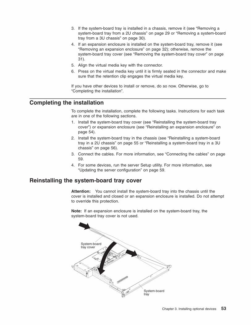
3. If the system-board tray is installed in a chassis, remove it (see “Removing asystem-board tray from a 2U chassis” on page 29 or “Removing a system-boardtray from a 3U chassis” on page 30).
4. If an expansion enclosure is installed on the system-board tray, remove it (see“Removing an expansion enclosure” on page 32); otherwise, remove thesystem-board tray cover (see “Removing the system-board tray cover” on page31).
5. Align the virtual media key with the connector.
6. Press on the virtual media key until it is firmly seated in the connector and makesure that the retention clip engages the virtual media key.
If you have other devices to install or remove, do so now. Otherwise, go to“Completing the installation”.
Completing the installationTo complete the installation, complete the following tasks. Instructions for each taskare in one of the following sections.
1. Install the system-board tray cover (see “Reinstalling the system-board traycover”) or expansion enclosure (see “Reinstalling an expansion enclosure” onpage 54).
2. Install the system-board tray in the chassis (see “Reinstalling a system-boardtray in a 2U chassis” on page 55 or “Reinstalling a system-board tray in a 3Uchassis” on page 56).
3. Connect the cables. For more information, see “Connecting the cables” on page59.
4. For some devices, run the server Setup utility. For more information, see“Updating the server configuration” on page 59.
Reinstalling the system-board tray cover
Attention: You cannot install the system-board tray into the chassis until thecover is installed and closed or an expansion enclosure is installed. Do not attemptto override this protection.
Note: If an expansion enclosure is installed on the system-board tray, thesystem-board tray cover is not used.
System-boardtray cover
System-boardtray
Chapter 3. Installing optional devices 53

To reinstall the system-board tray cover, complete the following steps:
1. Lower the cover so that the pins at the rear slide down into the slots at the rearof the system-board tray. Before you close the cover, make sure that allcomponents are installed and seated correctly, all internal cables are correctlyrouted, and you have not left loose tools or parts inside the system-board tray.
2. Pivot the cover to the closed position until it clicks into place.
3. Install the system-board tray in the chassis (see “Reinstalling a system-boardtray in a 2U chassis” on page 55 or “Reinstalling a system-board tray in a 3Uchassis” on page 56).
Reinstalling an expansion enclosure
Attention: You cannot install the system-board tray into the chassis until thecover is installed and closed or an expansion enclosure is installed. Do not attemptto override this protection.
Expansionenclosure
System-boardtray
To reinstall an expansion enclosure, complete the following steps:
1. Orient the expansion enclosure above the system-board tray.
2. Lower the expansion enclosure so that the pins at the rear slide down into theslots at the rear of the system-board tray. Before you close the cover, makesure that all components are installed and seated correctly, all internal cablesare correctly routed, and you have not left loose tools or parts inside thesystem-board tray.
3. If you disconnected cables when you removed the enclosure, reconnect them.
4. Pivot the expansion enclosure down onto the system-board tray until it clicksinto place.
5. Install the system-board tray in the chassis (see “Reinstalling a system-boardtray in a 2U chassis” on page 55).
54 System x iDataPlex dx360 M3: User's Guide

Reinstalling a system-board tray in a 2U chassis
To reinstall a system-board tray in a 2U chassis, complete the following steps:
1. If an expansion enclosure is installed on the system-board tray, make sure thatthe blue air damper actuator is parallel to the system-board tray before you slidethe assembly into the chassis.
2. Slide the system-board tray into the chassis until it stops and the releasehandles click into place.
3. Reconnect the cables on the front of the system-board tray.
4. Turn on the system-board tray (see “Turning on the system-board tray” on page23).
5. Make sure that the power-on LED on the system-board tray operator panel is litcontinuously, indicating that the system-board tray is receiving power and isturned on.
If you have changed the configuration of the system-board tray, you might have toupdate the server configuration through the Setup utility (see “Updating the serverconfiguration” on page 59).
Chapter 3. Installing optional devices 55

Reinstalling a system-board tray in a 3U chassis
Note: You must remove the 3U chassis from the iDataPlex rack before you installthe system-board tray (see “Removing a 3U chassis from an iDataPlex rack” onpage 28).
To reinstall a system-board tray in a 3U chassis, complete the following steps:
1. Slide the system-board tray into the 3U chassis until it stops.
2. Reconnect the cables that connect the system-board tray and optional adapterto the 3U chassis.
3. Turn the fan assembly so that the connector aligns correctly with the connectorin the power supply.
4. Insert the fan assembly into the 3U chassis. Firmly press the fan assemblystraight down into the chassis by applying pressure on both fan-assemblyhandles simultaneously.
5. Reinstall the retention bracket that secures the fan assembly.
56 System x iDataPlex dx360 M3: User's Guide

6. Connect the battery cable to the battery cable interposer card.
7. Align the ServeRAID SAS controller with the connector and the bracket on thestorage-riser-card assembly and press the controller into place.
Attention: When you move the storage-riser-card assembly, do not allow itto touch any components or structures inside the 3U chassis.
8. Align the storage-riser-card assembly with the guide pins and the slot in thesystem-board tray cover.
9. Press the assembly into place on the bracket.
10. Reconnect the signal cables to the ServeRAID SAS controller.
11. Align the top-cover assembly with the rear of the 3U chassis; then, slide itforward until it clicks into place.
12. Reinstall the 3U chassis in the iDataPlex rack (see “Reinstalling a 3U chassisin an iDataPlex rack” on page 58).
13. Install the hard disk drives (see “Installing a hard disk drive” on page 45).
14. Reconnect the cables on the front of the system-board tray.
15. Turn on the system-board tray (see “Turning on the system-board tray” onpage 23).
16. Make sure that the power-on LED on the system-board tray operator panel islit continuously, indicating that the system-board tray is receiving power and isturned on.
Chapter 3. Installing optional devices 57

If you have changed the configuration of the system-board tray, you might have toupdate the server configuration through the Setup utility (see “Updating the serverconfiguration” on page 59).
Reinstalling a 3U chassis in an iDataPlex rack
Statement 4:
≥ 18 kg (39.7 lb) ≥ 32 kg (70.5 lb) ≥ 55 kg (121.2 lb)
CAUTION:Use safe practices when lifting.
To reinstall a 3U chassis in an iDataPlex rack, complete the following steps:
1. Align the 3U chassis with the rails on the iDataPlex rack; then, slide the 3Uchassis into the rack until it is fully seated.
2. Install the M6 screws that secure the chassis to the rack.
3. Install the hard disk drives (see “Installing a hard disk drive” on page 45).
4. Reconnect the cables on the front of the system-board tray.
5. Turn on the system-board tray (see “Turning on the system-board tray” on page23).
6. Make sure that the power-on LED on the system-board tray operator panel is litcontinuously, indicating that the system-board tray is receiving power and isturned on.
58 System x iDataPlex dx360 M3: User's Guide

If you have changed the configuration of the system-board tray, you might have toupdate the server configuration through the Setup utility (see “Updating the serverconfiguration”).
Connecting the cables
Attention: To prevent damage to equipment, connect cables before you turn onthe system-board tray.
All cable connections, other than power, are on the front of the server. See“Operator panel controls, connectors, LEDs, and power” on page 21 for connectorlocations.
Updating the server configurationWhen you start the server for the first time after you add or remove a device, youmight receive a message that the configuration has changed. The Setup utilitystarts automatically so that you can save the new configuration settings. For moreinformation, see Chapter 4, “Configuring the dx360 M3 server,” on page 61.
Some optional devices have device drivers that you must install. For informationabout installing device drivers, see the documentation that comes with each device.
If the server has an optional RAID adapter and you have installed or removed ahard disk drive, see the documentation that comes with the RAID adapter forinformation about reconfiguring the disk arrays. For more information about theRAID controller, go to http://www-304.ibm.com/jct01004c/systems/support/supportsite.wss/docdisplay?lndocid=MIGR-65723&brandind=5000008 or completethe following steps.
Important: Some cluster solutions require specific code levels or coordinated codeupdates. If the device is part of a cluster solution, verify that the latest level of codeis supported for the cluster solution before you update the code.
Note: Changes are made periodically to the IBM Web site. The actual proceduremight vary slightly from what is described in this document.
1. Go to http://www.ibm.com/systems/support/.
2. Under Product support, click Hardware upgrades.
3. Under Product family, click RAID.
4. Under Type, click the type of RAID controller that is installed in your server.
For information about configuring the integrated Gigabit Ethernet controller, see“Configuring the Gigabit Ethernet controller” on page 71.
Chapter 3. Installing optional devices 59

60 System x iDataPlex dx360 M3: User's Guide

Chapter 4. Configuring the dx360 M3 server
To update the firmware, you might have to use an external USB CD-RW/DVD drivesuch as the IBM and Lenovo part number 73P4515 or 73P4516. To run the Setuputility or the Dynamic System Analysis (DSA) Preboot diagnostic program, you musthave the following additional hardware:
v Monitor
v Combination USB keyboard and pointing device such as IBM part number40K5372
Optionally, to run the DSA Preboot diagnostic program, you can use a USB flashdrive (memory key). A USB flash drive is provided in the accessory carton thatcomes with the configured rack solution.
The following configuration programs come with the dx360 M3 server:
v Setup utility
Use the Setup utility to configure low-level system settings, such as thestartup-device sequence, date and time, and passwords. For information aboutusing this program, see “Using the Setup utility” on page 62.
v Boot Menu program
The Boot Menu program is part of the UEFI firmware. Use it to override thestartup sequence that is set in the Setup utility and temporarily assign a device tobe first in the startup sequence. For information about using this program, see“Using the Boot Menu program” on page 67.
v Integrated management module
Use the integrated management module (IMM) for configuration, to update thefirmware and sensor data record/field replaceable unit (SDR/FRU) data, and toremotely manage a network. For information about using the IMM, see “Using theintegrated management module” on page 68.
v Remote presence capability and blue-screen capture
The remote presence and blue-screen capture feature are integrated into theintegrated management module (IMM). The virtual media key is required toenable these features. When the optional virtual media key is installed in theserver, it activates the remote presence functions. Without the virtual media key,you will not be able to access the network remotely to mount or unmount drivesor images on the client system. However, you will still be able to access the hostgraphical user interface through the web interface without the virtual media key.You can order the optional IBM Virtual Media Key, if one did not come with yourserver. For more information about how to enable the remote presence function,see “Using the remote presence capability and blue-screen capture” on page 69.
v IBM Advanced Settings Utility (ASU)
Use ASU to modify firmware settings from the command line without the need torestart the system to access the Setup utility. You can also use ASU to issueselected IMM setup commands. The ASU supports scripting environmentsthrough its batch-processing mode. For information about using this program, see“IBM Advanced Settings Utility program” on page 71.
v Ethernet controller configuration
For information about configuring the Ethernet controller, see “Configuring theGigabit Ethernet controller” on page 71.
v LSI Logic Configuration Utility program
© Copyright IBM Corp. 2011 61
Some server configurations use the LSI Logic Configuration Utility program toconfigure an optional LSI RAID controller and the devices that are attached to it.For information about using this program, see “Using the LSI Logic ConfigurationUtility program” on page 72.
v ServeRAID configuration program
Some server configurations use the ServeRAID configuration program toconfigure an optional ServeRAID controller and the devices that are attached toit. For information about using this program, see “Configuring a ServeRAIDcontroller” on page 74.
v IBM Electronic Service Agent™
IBM Electronic Service Agent is a software tool that monitors the server forhardware error events and automatically submits electronic service requests toIBM service and support. Also, it can collect and transmit system configurationinformation on a scheduled basis so that the information is available to you andyour support representative. It uses minimal system resources, is available freeof charge, and can be downloaded from the Web. For more information and todownload Electronic Service Agent, go to http://www.ibm.com/support/electronic/.
v IBM Dynamic System Analysis (DSA) Preboot Diagnostic Programs
The IBM Dynamic System Analysis (DSA) Preboot diagnostic programs are theprimary method of testing the major components of an IBM System x iDataPlexserver. You can use the USB flash drive that comes with the iDataPlex rack whenyou run the DSA Preboot diagnostic programs on an iDataPlex server.
To download the most current USB or ISO image of the DSA Preboot diagnosticprograms go to http://www.ibm.com/support/docview.wss?uid=psg1SERV-DSA.
For additional information about the DSA diagnostic programs, see the ProblemDetermination and Service Guide for the iDataPlex server on the IBMDocumentation CD that comes with the iDataPlex rack solution.
v IBM Storage Configuration Manager (SCM)
Use SCM to manage the storage configuration of your virtual environment from asingle console. SCM is part of the Virtualization Manager plug-in to IBM SystemsDirector. For more information and to download the Storage ConfigurationManager, go to http://www.ibm.com/systems/support/.
v IBM Systems Director
IBM Systems Director is a platform-management foundation that streamlines theway you manage physical and virtual systems in a heterogeneous environment.For information about updating IBM Systems Director, see “Updating IBMSystems Director” on page 75.
Using the Setup utilityUse the Setup utility to perform the following tasks:
v View configuration information
v View and change assignments for devices and I/O ports
v Set the date and time
v Set the startup characteristics of the server and the order of startup devices
v Set and change settings for advanced hardware features
v View, set, and change settings for power-management features
v View and clear error logs
v Resolve configuration conflicts
62 System x iDataPlex dx360 M3: User's Guide

Starting the Setup utilityTo start the Setup utility, complete the following steps:
1. Turn on the server.
2. When the prompt <F1> Setup is displayed, press F1. If you have set both apower-on password and an administrator password, you must type theadministrator password to access the full Setup utility menu. If you do not typethe administrator password, a limited Setup utility menu is available.
3. Select settings to view or change.
Setup utility menu choicesThe following choices are on the Setup utility main menu. Depending on the versionof the firmware, some menu choices might differ slightly from these descriptions.
v System Information
Select this choice to view information about the server. When you make changesthrough other choices in the Setup utility, some of those changes are reflected inthe system information; you cannot change settings directly in the systeminformation.
– System Summary
Select this choice to view configuration information, including the ID, speed,and cache size of the microprocessors, machine type and model of the server,the serial number, the system UUID, and the amount of installed memory.When you make configuration changes through other options in the Setuputility, the changes are reflected in the system summary; you cannot changesettings directly in the system summary.
– Product Data
Select this choice to view the system-board identifier, the revision level orissue date of the firmware, the integrated management module anddiagnostics code, and the version and date.
v System Settings
Select this choice to view or change the server component settings.
– Processors
Select this choice to view or change the processor settings.
– Memory
Select this choice to view or change the memory settings. To configurememory mirroring, select System Settings → Memory , and then selectMemory Channel Mode → Mirroring.
– Devices and I/O Ports
Select this choice to view or change assignments for devices and input/output(I/O) ports. You can configure the serial ports; configure remote consoleredirection; enable or disable integrated Ethernet controllers, the SAS/SATAcontroller, SATA optical drive channels, and PCI slots; and view the systemEthernet MAC addresses. If you disable a device, it cannot be configured, andthe operating system will not be able to detect it (this is equivalent todisconnecting the device).
– Power
Select this choice to view or change power capping to control consumption,processors, and performance states.
– Operating Modes
Optimize system for minimum power usage/acoustic level, power efficiency, orperformance.
Chapter 4. Configuring the dx360 M3 server 63

– Legacy Support
Select this choice to view or set legacy support.
- Force Legacy Video on Boot
Select this choice to force INT video support, if the operating system doesnot support UEFI Video Output Standards.
- Rehook INT
Select this choice to enable or disable devices from taking control of theboot process. The default is Disable.
- Legacy Thunk Support
Select this choice to enable or disable legacy thunk support.
– Integrated Management Module
Select this choice to view or change the settings for the integratedmanagement module.
- POST Watchdog Timer
Select this choice to view or enable the POST watchdog timer.
- POST Watchdog Timer Value
Select this choice to view or set the POST loader watchdog timer value.
- Reboot System on NMI
Enable or disable restarting the system whenever a nonmaskable interrupt(NMI) occurs. Disabled is the default.
- Network Configuration
Select this choice to view the system management network interface port,the IMM MAC address, the current IMM IP address, and host name; definethe static IMM IP address, subnet mask, and gateway address; specifywhether to use the static IP address or have DHCP assign the IMM IPaddress; save the network changes; and reset the IMM.
- Reset IMM to Defaults
Select this choice to view or reset IMM to the default settings.
– System Security
Select this choice to view or set the Trusted Platform Module (TPM) options.
- TPM Physical Presence
Select this choice to display the current state of the TPM physicalpresence. This must be asserted for TPM commands to succeed.
- Refresh TPM Physical Presence State
Select this choice to refresh the current state of the TPM physicalpresence.
- TPM Enabled Status
Select this choice to enable/disable and activate/deactivate state of theTPM.
- TPM Device
Select this choice to enable/disable the TPM device. This commandrequires the TPM physical presence to be asserted.
- TPM State
Select this choice to activate/deactivate the TPM device. This commandrequires the TPM physical presence to be asserted.
- TPM Force Clear
64 System x iDataPlex dx360 M3: User's Guide

Select this choice to force clearing TPM data. !!! Warning !!! This willerase the contents of the TPM. This command requires the TPM physicalpresence to be asserted.
– Adapters and UEFI Drivers
Select this choice to view information about the adapters and UEFI drivers inthe server.
– Network
Select this choice to see all of the device options, such as the iSCSI, PXE,and Ethernet parameters.
v Date and Time
Select this choice to set the date and time in the server, in 24-hour format(hour:minute:second).
v Start Options
Select this choice to view or change the start options, including the startupsequence, keyboard NumLock state, PXE boot option, and PCI device bootpriority. Changes in the startup options take effect when you start the server.
The startup sequence specifies the order in which the server checks devices tofind a boot record. The server starts from the first boot record that it finds. If theserver has Wake on LAN hardware and software and the operating systemsupports Wake on LAN functions, you can specify a startup sequence for theWake on LAN functions. For example, you can define a startup sequence thatchecks for a disc in the CD-RW/DVD drive, then checks the hard disk drive, andthen checks a network adapter.
This choice is on the full Setup utility menu only.
v Boot Manager
Select this choice to view, add, or change the device boot priority, boot from afile, select a one-time boot, or reset the boot order to the default setting.
v System Event Logs
Select this choice to enter the System Event Manager, where you can view theerror messages in the system event logs. You can use the arrow keys to movebetween pages in the error log.
The system event logs contain all event and error messages that have beengenerated during POST, by the systems-management interface handler, and bythe system service processor. Run the diagnostic programs to get moreinformation about error codes that occur. See the Problem Determination andService Guide on the IBM Documentation CD for instructions for running thediagnostic programs.
Important: If the system-error LED on the front of the server is lit but there areno other error indications, clear the system-event log. Also, after you complete arepair or correct an error, clear the system-event log to turn off the system-errorLED on the front of the server.
– POST Event Viewer
Select this choice to view the error messages in the POST event viewer.
– System Event Log
Select this choice to view the error messages in the system-event log.
– Clear System Event Log
Select this choice to clear the system-event log.
v User Security
Select this choice to set, change, or clear passwords. See“Passwords” on page66 for more information.
Chapter 4. Configuring the dx360 M3 server 65

This choice is on the full and limited Setup utility menu.
– Set Power-on Password
Select this choice to set or change a power-on password. For moreinformation, see “Power-on password” on page 67.
– Clear Power-on Password
Select this choice to clear a power-on password. For more information, see“Power-on password” on page 67.
– Set Administrator Password
Select this choice to set or change an administrator password. Anadministrator password is intended to be used by a system administrator; itlimits access to the full Setup utility menu. If an administrator password is set,the full Setup utility menu is available only if you type the administratorpassword at the password prompt. For more information, see “Administratorpassword” on page 67.
– Clear Administrator Password
Select this choice to clear an administrator password. For more information,see “Administrator password” on page 67.
v Save Settings
Select this choice to save the changes that you have made in the settings.
v Restore Settings
Select this choice to cancel the changes that you have made in the settings andrestore the previous settings.
v Load Default Settings
Select this choice to cancel the changes that you have made in the settings andrestore the factory settings.
v Exit Setup
Select this choice to exit from the Setup utility. If you have not saved thechanges that you have made in the settings, you are asked whether you want tosave the changes or exit without saving them.
PasswordsFrom the User Security choice, you can set, change, and delete a power-onpassword and an administrator password. The User Security choice is on the fullSetup utility menu only.
If you set only a power-on password, you must type the power-on password tocomplete the system startup and to have access to the full Setup utility menu.
An administrator password is intended to be used by a system administrator; itlimits access to the full Setup utility menu. If you set only an administratorpassword, you do not have to type a password to complete the system startup, butyou must type the administrator password to access the Setup utility menu.
If you set a power-on password for a user and an administrator password for asystem administrator, you can type either password to complete the system startup.A system administrator who types the administrator password has access to the fullSetup utility menu; the system administrator can give the user authority to set,change, and delete the power-on password. A user who types the power-onpassword has access to only the limited Setup utility menu; the user can set,change, and delete the power-on password, if the system administrator has giventhe user that authority.
66 System x iDataPlex dx360 M3: User's Guide

Power-on passwordIf a power-on password is set, when you turn on the server, the system startup willnot be completed until you type the power-on password. You can use anycombination of up to seven characters (A – Z, a – z, and 0 – 9) for the password.
If you forget the power-on password, you can regain access to the server in any ofthe following ways:
v If an administrator password is set, type the administrator password at thepassword prompt. Start the Setup utility and reset the power-on password.
v Clear the password by clearing CMOS memory (see the Problem Determinationand Service Guide for instructions).
Administrator passwordAn administrator password is intended to be used by a system administrator; itlimits access to the full Setup utility menu.
If an administrator password is set, you must type the administrator password foraccess to the full Setup utility menu. You can use any combination of up to sevencharacters (A – Z, a – z, and 0 – 9) for the password.
Attention: If you set an administrator password and then forget it, there is no wayto change, override, or remove it. You must replace the system board.
Using the Boot Menu programThe Boot Menu program is a built-in, menu-driven configuration utility program thatyou can use to temporarily redefine the first startup device without changingsettings in the Setup utility.
To use the Boot Menu program, complete the following steps:
1. Turn off the server.
2. Restart the server.
3. Press F12 (Select Boot Device). If a bootable USB mass storage device isinstalled, a submenu item (USB Key/Disk) is displayed.
4. Use the Up Arrow and Down Arrow keys to select an item from the BootSelection Menu and press Enter.
The next time the server starts, it returns to the startup sequence that is set in theSetup utility.
Starting the backup UEFI firmwareThe system board contains a backup copy area for the UEFI (formerly called BIOS)firmware. This is a secondary copy of UEFI firmware that you update only duringthe process of updating UEFI firmware. If the primary copy of the UEFI firmwarebecomes damaged, use this backup copy.
To force the server to start from the backup copy, turn off the server; then, place theJP2 jumper in the backup position (pins 2 and 3). See “System-board jumpers” onpage 16 for the location of the JP2 jumper.
Use the backup copy of the UEFI firmware until the primary copy is restored. Afterthe primary copy is restored, turn off the server; then, move the JP2 jumper back tothe primary position (pins 1 and 2).
Chapter 4. Configuring the dx360 M3 server 67
Using the integrated management moduleThe integrated management module (IMM) is a second generation of the functionsthat were formerly provided by the baseboard management controller hardware. Itcombines service processor functions, video controller, and (when an optionalvirtual media key is installed) remote presence function in a single chip.
The IMM supports the following basic systems-management features:
v Environmental monitor with fan speed control for temperature, voltages, fanfailure, and power supply failure.
v Diagnostic LEDs to report errors that occur with power supplies, microprocessor,hard disk drives, and system errors.
v DIMM error assistance. The Unified Extensible Firmware Interface (UEFI)disables a failing DIMM that is detected during POST, and the IMM lights theassociated system error LED and the failing DIMM error LED.
v System-event log.
v ROM-based IMM firmware flash updates.
v Auto Boot Failure Recovery.
v A virtual media key, which enables full systems-management support (remotevideo, remote keyboard/mouse, and remote storage).
v When one of the two microprocessors reports an internal error, the serverdisables the defective microprocessor and restarts with the one goodmicroprocessor.
v NMI detection and reporting.
v SMI handling.
v Automatic Server Restart (ASR) when POST is not complete or the operatingsystem hangs and the OS watchdog timer times out. The IMM might beconfigured to watch for the OS watchdog timer and reboot the system after atimeout, if the ASR feature is enabled. Otherwise, the IMM allows theadministrator to generate an NMI by pressing an NMI button on the system boardfor an operating-system memory dump. ASR is supported by IPMI.
v Intelligent Platform Management Interface (IPMI) Specification V2.0 andIntelligent Platform Management Bus (IPMB) support.
v Invalid system configuration (CNFG) LED support.
v Serial redirect.
v Serial over LAN (SOL).
v Active Energy Manager.
v Query power-supply input power.
v PECI 2 support.
v Power/reset control (power-on, hard and soft shutdown, hard and soft reset,schedule power control).
v Alerts (in-band and out-of-band alerting, PET traps - IPMI style, SNMP, e-mail).
v Operating-system failure blue screen capture.
v Command-line interface.
v Configuration save and restore.
v PCI configuration data.
v Boot sequence manipulation.
The IMM also provides the following remote server management capabilitiesthrough the OSA SMBridge management utility program:
68 System x iDataPlex dx360 M3: User's Guide
v Command-line interface (IPMI Shell)
The command-line interface provides direct access to server managementfunctions through the IPMI 2.0 protocol. Use the command-line interface to issuecommands to control the server power, view system information, and identify theserver. You can also save one or more commands as a text file and run the fileas a script.
v Serial over LAN
Establish a Serial over LAN (SOL) connection to manage servers from a remotelocation. You can remotely view and change the UEFI settings, restart the server,identify the server, and perform other management functions. Any standard Telnetclient application can access the SOL connection.
Using the remote presence capability and blue-screen captureThe remote presence and blue-screen capture features are integrated functions ofthe integrated management module (IMM). When the optional IBM Virtual MediaKey is installed in the server, it activates full systems-management functions. Thevirtual media key is required to enable the integrated remote presence andblue-screen capture features. Without the virtual media key, you cannot remotelymount or unmount drives or images on the client system. However, you still canaccess the Web interface without the key.
After the virtual media key is installed in the server, it is authenticated to determinewhether it is valid. If the key is not valid, you receive a message from the Webinterface (when you attempt to start the remote presence feature) indicating that thehardware key is required to use the remote presence feature.
The virtual media key has an LED. When this LED is lit and green, it indicates thatthe key is installed and functioning correctly.
The remote presence feature provides the following functions:
v Remotely viewing video with graphics resolutions up to 1280 x 1024 at 75 Hz,regardless of the system state
v Remotely accessing the server, using the keyboard and mouse from a remoteclient
v Mapping the CD or DVD drive, diskette drive, and USB flash drive on a remoteclient, and mapping ISO and diskette image files as virtual drives that areavailable for use by the server
v Uploading a diskette image to the IMM memory and mapping it to the server as avirtual drive
The blue-screen capture feature captures the video display contents before the IMMrestarts the server when the IMM detects an operating-system hang condition. Asystem administrator can use the blue-screen capture to assist in determining thecause of the hang condition.
Enabling the remote presence featureTo enable the remote presence feature, complete the following steps:
1. Install the virtual media key into the dedicated slot on the system board (see“Installing an IBM virtual media key” on page 52).
2. Turn on the server.
Chapter 4. Configuring the dx360 M3 server 69
Note: Approximately 1 to 2 minutes after the server is connected to ac power,the power-control button becomes active.
Obtaining the IP address for the Web interface accessTo access the Web interface and use the remote presence feature, you need the IPaddress for the IMM. You can obtain the IMM IP address through the Setup utility.To locate the IP address, complete the following steps:
1. Turn on the server.
Note: Approximately 1 to 2 minutes after the server is connected to ac power,the power-control button becomes active.
2. When the prompt <F1> Setup is displayed, press F1. (This prompt is displayedon the screen for only a few seconds. You must press F1 quickly.) If you haveset both a power-on password and an administrator password, you must typethe administrator password to access the full Setup utility menu.
3. From the Setup utility main menu, select System Settings.
4. On the next screen, select Integrated Management Module.
5. On the next screen, select Network Configuration.
6. Find the IP address and write it down.
7. Exit from the Setup utility.
Logging on to the Web interfaceTo log on to the Web interface to use the remote presence functions, complete thefollowing steps:
1. Open a Web browser on a computer that connects to the server and in theaddress or URL field, type the IP address or host name of the IMM to whichyou want to connect.
Notes:
a. If you are logging in to the IMM for the first time after installation, the IMMdefaults to DHCP. If a DHCP host is not available, the IMM uses the defaultstatic IP address 192.168.70.125.
b. You can obtain the DHCP-assigned IP address or the static IP address fromthe server UEFI or from your network administrator.
The Login page is displayed.
2. Type the user name and password. If you are using the IMM for the first time,you can obtain the user name and password from your system administrator. Alllogin attempts are documented in the event log. A welcome page opens in yourbrowser.
Note: The IMM is set initially with a user name of USERID and password ofPASSW0RD (passw0rd with a zero, not a the letter O). You have read/writeaccess. For enhanced security, change this default password during your initialconfiguration.
3. On the Welcome page, type a timeout value (in minutes) in the field that isprovided. The IMM will log you off of the Web interface if your browser isinactive for the number of minutes that you entered for the timeout value.
4. Click Continue to start the session. The browser opens the System Statuspage, which gives you a quick view of the server status and the server healthsummary.
70 System x iDataPlex dx360 M3: User's Guide

IBM Advanced Settings Utility programThe Advanced Settings Utility (ASU) program is an alternative to the Setup utility formodifying UEFI settings. Use the ASU program online or out of band to modifyUEFI settings from the command line without the need to restart the system toaccess the Setup utility.
You can also use the ASU program to configure the optional remote presencefeatures or other IMM settings. The remote presence features provide enhancedsystems-management capabilities.
In addition, the ASU program provides limited settings for configuring the IPMIfunction in the IMM through the command-line interface.
Use the command-line interface to issue setup commands. You can save any of thesettings as a file and run the file as a script. The ASU program supports scriptingenvironments through a batch-processing mode.
For more information and to download the ASU program, go tohttp://www.ibm.com/systems/support/.
Configuring the Gigabit Ethernet controllerThe Ethernet controller is integrated on the system board. It provides an interfacefor connecting to a 10 Mbps, 100 Mbps, or 1 Gbps network and provides full-duplex(FDX) capability, which enables simultaneous transmission and reception of data onthe network. If the Ethernet ports in the server support auto-negotiation, thecontroller detects the data-transfer rate (10BASE-T, 100BASE-TX, or 1000BASE-T)and duplex mode (full-duplex or half-duplex) of the network and automaticallyoperates at that rate and mode.
You do not have to set any jumpers or configure the controller. However, you mustinstall a device driver to enable the operating system to address the controller. Tofind updated information about configuring the controller, complete the followingsteps.
Important: Some cluster solutions require specific code levels or coordinated codeupdates. If the device is part of a cluster solution, verify that the latest level of codeis supported for the cluster solution before you update the code.
Notes:
v Changes are made periodically to the IBM Web site. The actual procedure mightvary slightly from what is described in this document.
v To install the device driver for the Ethernet controller, you might have to use anexternal USB CD-RW/DVD drive such as the IBM and Lenovo part number73P4515 or 73P4516. See “Firmware updates” on page 74 for additionalinstructions about using an external USB CD-RW/DVD drive.
1. Go to http://www.ibm.com/systems/support/.
2. Under Product support, click System x.
3. Under Popular links, click Software and device drivers.
4. From the Product family menu, select System x iDataPlex dx360 M3 serverand click Go.
Chapter 4. Configuring the dx360 M3 server 71

Using the LSI Logic Configuration Utility programUse the information in this section to configure an optional LSI RAID controller. Ifyou need to configure an optional ServeRAID controller, see “Configuring aServeRAID controller” on page 74.
Use the LSI Logic Configuration Utility program to configure and manage redundantarray of independent disks (RAID) arrays. Be sure to use the program as describedin this document. Use the LSI Logic Configuration Utility program to perform thefollowing tasks:
v Perform a low-level format of a SCSI hard disk drive
v View or change SCSI IDs for attached devices
v Set a SCSI device scan order
v Set SCSI protocol parameters on SCSI hard disk drives
v Configure arrays
v View your RAID configuration and associated devices
v Monitor operation of your RAID controllers
v Create a mirrored pair of SCSI hard disk drives with or without a hot-spare drive
The integrated SCSI controller with RAID capabilities supports redundant array ofindependent disks (RAID) arrays. You can use the LSI Logic Configuration Utilityprogram to configure RAID level-1 for a single pair of attached devices. If you installa different type of RAID adapter, follow the instructions in the documentation thatcomes with the adapter to view or change SCSI settings for attached devices.
You can download an LSI command-line configuration program (CFG1030) fromhttp://www.ibm.com/systems/support/. For more information about the RAIDcontroller, go to http://www-304.ibm.com/jct01004c/systems/support/supportsite.wss/docdisplay?lndocid=MIGR-65723&brandind=5000008 or complete the followingsteps.
Note: Changes are made periodically to the IBM Web site. The actual proceduremight vary slightly from what is described in this document.
1. Go to http://www.ibm.com/systems/support/.
2. Under Product support, click Hardware upgrades.
3. Under Product family, click RAID.
4. Under Type, click on the type of RAID controller that is installed in your server.
When you use the LSI Logic Configuration Utility program to configure and managearrays, review the following information:
v The integrated SCSI controller with RAID capabilities in the server supports onlyRAID level-1 with a hot-spare drive installed. Installing an optional ServeRAIDcontroller provides additional RAID levels.
v When you create a RAID level-1 (mirrored) pair, all drives must be on the samechannel.
v Hard disk drive capacities affect how you create arrays. The drives in an arraycan have different capacities, but the RAID controller treats them as if they allhave the capacity of the smallest hard disk drive.
v You can set up a mirror after the operating system is installed on the primarydrive only if you are using an integrated SCSI controller with RAID capabilities.You must make sure that the primary drive has the lower SCSI ID (for example,0).
72 System x iDataPlex dx360 M3: User's Guide

Important: If you use an integrated SCSI controller with RAID capabilities toconfigure a RAID level-1 (mirrored) array after you have installed the operatingsystem, you will lose access to any data or applications that were previouslystored on the secondary drive of the mirrored pair.
v If you install a different type of RAID controller, follow the instructions in thedocumentation that comes with the controller to view or change SCSI settings forattached devices.
The following sections provide instructions for starting the LSI Logic ConfigurationUtility program and performing selected functions.
Starting the LSI Logic Configuration Utility programTo start the LSI Logic Configuration Utility program, complete the following steps:
1. Turn on the server.
2. When the prompt <<< Press <CTRL><C> to start LSI Logic ConfigurationUtility >>> is displayed, press Ctrl+C. If you have set an administratorpassword, you are prompted to type the password.
3. To select a controller (channel) from the list of adapters, use the arrow keys andpress Enter.
4. To change the settings of the selected items, follow the instructions on thescreen. If you select Device Properties or Mirroring Properties, additionalscreens are displayed.
When you have finished changing settings, press Esc to exit from the program;select Save to save the settings that you have changed.
Formatting a SCSI hard disk driveLow-level formatting removes all data from the hard disk. If there is data on the diskthat you want to save, back up the hard disk before you perform this procedure.
Note: Before you format a SCSI hard disk, make sure that the disk is not part of amirrored pair. From the list of adapters, select the controller (channel) for the drivethat you want to format. Select Mirroring Properties and make sure that themirroring value for the drive is None.
To format a drive, complete the following steps:
1. From the list of adapters, select the controller (channel) for the drive that youwant to format.
2. Select Device Properties.
3. To highlight the drive that you want to format, use the Up Arrow and DownArrow keys. To scroll left and right, use the Left Arrow and Right Arrow keys orthe End key.
4. To start the low-level formatting operation, select Format and press Enter.
Creating a mirrored pair of SCSI hard disk drivesTo create a mirrored pair of SCSI hard disk drives, complete the following steps:
1. From the list of adapters, select the controller (channel) for the drives that youwant to mirror.
2. Select Mirroring Properties.
3. Use the arrow keys to highlight the first drive in the pair; then, press the Minuskey to change the mirroring value to Primary.
Chapter 4. Configuring the dx360 M3 server 73

4. Use the arrow keys to highlight the second drive in the pair; then, press theMinus key to change the mirroring value to Secondary.
5. To establish a third drive that will take over the function of either mirrored drivein the event of a failure, use the arrow keys to highlight the drive that you wantto use for that purpose; then, press the Minus key to change the mirroring valueto Hot Spare.
Configuring a ServeRAID controllerUse the information in this section to configure an optional ServeRAID controller. Ifyou need to configure an optional LSI RAID controller, see “Using the LSI LogicConfiguration Utility program” on page 72.
Important: Some cluster solutions require specific code levels or coordinated codeupdates. If the device is part of a cluster solution, verify that the latest level of codeis supported for the cluster solution before you update the code.
To update the firmware and UEFI code for an optional ServeRAID controller, youmust use the IBM ServeRAID Support CD that comes with the controller.
Note: To update the firmware and UEFI code for an optional ServeRAID controller,you might have to use an external USB CD-RW/DVD drive such as the IBM andLenovo part number 73P4515 or 73P4516. See “Firmware updates” for additionalinstructions about using an external USB CD-RW/DVD drive.
For more information about the ServeRAID controller, go to http://www-304.ibm.com/jct01004c/systems/support/supportsite.www/docdisplay?lndocid=MIGR-4JTS2T&brandind=5000008 or complete the following steps.
Note: Changes are made periodically to the IBM Web site. The actual proceduremight vary slightly from what is described in this document.
1. Go to http://www.ibm.com/systems/support/.
2. Under Product support, click Hardware upgrades.
3. Under Product family, click RAID.
4. Under Type, click on the type of RAID controller that is installed in your server.
Firmware updates
Important: Some cluster solutions require specific code levels or coordinated codeupdates. If the device is part of a cluster solution, verify that the latest level of codeis supported for the cluster solution before you update the code.
The firmware for the server is periodically updated and is available for downloadfrom the Web. To check for the latest level of firmware, such as BIOS code, vitalproduct data (VPD) code, device drivers, and service processor firmware completethe following steps.
Note: Changes are made periodically to the IBM Web site. The actual proceduremight vary slightly from what is described in this document.
1. Go to http://www.ibm.com/systems/support/.
2. Under Product support, click System x.
3. Under Popular links, click Software and device drivers.
74 System x iDataPlex dx360 M3: User's Guide
4. Click System x iDataPlex dx360 M3 server to display the matrix ofdownloadable files.
Download the latest firmware for the server; then, install the firmware, using theinstructions that are included with the downloaded files.
When you replace a device in the server, you might have to either update theserver with the latest version of the firmware that is stored in memory on the deviceor restore the pre-existing firmware from a diskette or CD image.
v UEFI code is stored in ROM on the system board.
v IMM firmware is stored in ROM on the integrated management controller on thesystem board.
v Ethernet firmware is stored in ROM on the Ethernet controller.
v ServeRAID firmware is stored in ROM on the ServeRAID SAS controller.
v SAS firmware is stored in ROM on the ServeRAID SAS controller.
v Major components contain vital product data (VPD) code. You can select toupdate the VPD code during theUEFI code update procedure.
The following items are downloadable at http://www.ibm.com/systems/support/:
v Diagnostics programs
v IMM firmware
v Ethernet firmware
Important: To avoid problems and to maintain proper system performance, alwaysmake sure that the UEFI code, service processor, and other firmware levels areconsistent for all iDataPlex servers.
To update the firmware, you might have to use an external USB CD-RW/DVD drivesuch as the IBM and Lenovo part number 73P4515 or 73P4516. To use an externalUSB CD-RW/DVD drive to update the firmware, complete the following steps:
1. If the system-board tray is running, turn off the system-board tray and allattached devices.
2. Connect a USB CD or DVD drive to a USB connector on the front of thesystem-board tray.
3. Turn on all attached devices; then, turn on the system-board tray.
4. When the prompt <F1> Setup is displayed, press F1.
5. From the Setup utility menu, select Startup Options.
6. Note the device that is selected as the first startup device. Later, you mustrestore this setting.
7. Select CD/DVD-ROM as the first startup device.
8. Press Esc to return to the Setup utility menu.
9. Insert the CD or DVD containing the firmware update into the CD or DVDdrive.
10. Select Save Changes and Exit and follow the prompts.
Updating IBM Systems DirectorIf you plan to use IBM Systems Director to manage the server, you must check forthe latest applicable IBM Systems Director updates and interim fixes.
Chapter 4. Configuring the dx360 M3 server 75

To locate and install a newer version of IBM Systems Director, complete thefollowing steps:
Notes:
v Changes are made periodically to the IBM Web site. The actual procedure mightvary slightly from what is described in this document.
v To update IBM Systems Director software, you might have to use an externalUSB CD-RW/DVD drive such as the IBM and Lenovo part number 73P4515 or73P4516. See “Firmware updates” on page 74 for additional instructions aboutusing an external USB CD-RW/DVD drive.
1. Check for the latest version of IBM Systems Director:
a. Go to http://www.ibm.com/systems/management/director/downloads.html.
b. If a newer version of IBM Systems Director than what comes with the serveris shown in the drop-down list, follow the instructions on the Web page todownload the latest version.
2. Install the IBM Systems Director program.
If your management server is connected to the Internet, to locate and installupdates and interim fixes, complete the following steps:
1. Make sure that you have run the Discovery and Inventory collection tasks.
2. On the Welcome page of the IBM Systems Director Web interface, click Viewupdates.
3. Click Check for updates. The available updates are displayed in a table.
4. Select the updates that you want to install, and click Install to start theinstallation wizard.
If your management server is not connected to the Internet, to locate and installupdates and interim fixes, complete the following steps:
1. Make sure that you have run the Discovery and Inventory collection tasks.
2. On a system that is connected to the Internet, go to http://www.ibm.com/eserver/support/fixes/fixcentral/.
3. From the Product family list, select IBM Systems Director.
4. From the Product list, select IBM Systems Director.
5. From the Installed version list, select the latest version, and click Continue.
6. Download the available updates.
7. Copy the downloaded files to the management server.
8. On the management server, on the Welcome page of the IBM SystemsDirector Web interface, click the Manage tab, and click Update Manager.
9. Click Import updates and specify the location of the downloaded files that youcopied to the management server.
10. Return to the Welcome page of the Web interface, and click View updates.
11. Select the updates that you want to install, and click Install to start theinstallation wizard.
76 System x iDataPlex dx360 M3: User's Guide
Appendix A. Getting help and technical assistance
If you need help, service, or technical assistance or just want more informationabout IBM products, you will find a wide variety of sources available from IBM toassist you. This section contains information about where to go for additionalinformation about IBM and IBM products, what to do if you experience a problemwith your system, and whom to call for service, if it is necessary.
Before you callBefore you call, make sure that you have taken these steps to try to solve theproblem yourself:
v Check all cables to make sure that they are connected.
v Check the power switches to make sure that the system and any optionaldevices are turned on.
v Use the troubleshooting information in your system documentation, and use thediagnostic tools that come with your system. Information about diagnostic tools isin the Problem Determination and Service Guide on the IBM Documentation CDthat comes with your system.
v Go to the IBM support Web site at http://www.ibm.com/systems/support/ to checkfor technical information, hints, tips, and new device drivers or to submit arequest for information.
You can solve many problems without outside assistance by following thetroubleshooting procedures that IBM provides in the online help or in thedocumentation that is provided with your IBM product. The documentation thatcomes with IBM systems also describes the diagnostic tests that you can perform.Most systems, operating systems, and programs come with documentation thatcontains troubleshooting procedures and explanations of error messages and errorcodes. If you suspect a software problem, see the documentation for the operatingsystem or program.
Using the documentationInformation about your IBM system and preinstalled software, if any, or optionaldevice is available in the documentation that comes with the product. Thatdocumentation can include printed documents, online documents, readme files, andhelp files. See the troubleshooting information in your system documentation forinstructions for using the diagnostic programs. The troubleshooting information orthe diagnostic programs might tell you that you need additional or updated devicedrivers or other software. IBM maintains pages on the World Wide Web where youcan get the latest technical information and download device drivers and updates.To access these pages, go to http://www.ibm.com/systems/support/ and follow theinstructions. Also, some documents are available through the IBM PublicationsCenter at http://www.ibm.com/shop/publications/order/.
© Copyright IBM Corp. 2011 77

Getting help and information from the World Wide WebOn the World Wide Web, the IBM Web site has up-to-date information about IBMsystems, optional devices, services, and support. The address for IBM System xand xSeries information is http://www.ibm.com/systems/x/. The address for IBMiDataPlex information is http://www.ibm.com/systems/x/hardware/idataplex/index.html. The address for IBM BladeCenter information is http://www.ibm.com/systems/bladecenter/.
You can find service information for IBM systems and optional devices athttp://www.ibm.com/systems/support/.
Software service and supportThrough IBM Support Line, you can get telephone assistance, for a fee, with usage,configuration, and software problems with System x and xSeries servers,BladeCenter products, IntelliStation® workstations, and appliances. For informationabout which products are supported by Support Line in your country or region, seehttp://www.ibm.com/services/sl/products/.
For more information about Support Line and other IBM services, seehttp://www.ibm.com/services/, or see http://www.ibm.com/planetwide/ for supporttelephone numbers. In the U.S. and Canada, call 1-800-IBM-SERV(1-800-426-7378).
Hardware service and supportYou can receive hardware service through your IBM reseller or IBM Services. Tolocate a reseller authorized by IBM to provide warranty service, go tohttp://www.ibm.com/partnerworld/ and click Find a Business Partner on the rightside of the page. For IBM support telephone numbers, see http://www.ibm.com/planetwide/. In the U.S. and Canada, call 1-800-IBM-SERV (1-800-426-7378).
In the U.S. and Canada, hardware service and support is available 24 hours a day,7 days a week. In the U.K., these services are available Monday through Friday,from 9 a.m. to 6 p.m.
IBM Taiwan product service
IBM Taiwan product service contact information:IBM Taiwan Corporation3F, No 7, Song Ren Rd.Taipei, TaiwanTelephone: 0800-016-888
78 System x iDataPlex dx360 M3: User's Guide
Appendix B. Notices
This information was developed for products and services offered in the U.S.A.
IBM may not offer the products, services, or features discussed in this document inother countries. Consult your local IBM representative for information on theproducts and services currently available in your area. Any reference to an IBMproduct, program, or service is not intended to state or imply that only that IBMproduct, program, or service may be used. Any functionally equivalent product,program, or service that does not infringe any IBM intellectual property right may beused instead. However, it is the user's responsibility to evaluate and verify theoperation of any non-IBM product, program, or service.
IBM may have patents or pending patent applications covering subject matterdescribed in this document. The furnishing of this document does not give you anylicense to these patents. You can send license inquiries, in writing, to:
IBM Director of LicensingIBM CorporationNorth Castle DriveArmonk, NY 10504-1785U.S.A.
INTERNATIONAL BUSINESS MACHINES CORPORATION PROVIDES THISPUBLICATION “AS IS” WITHOUT WARRANTY OF ANY KIND, EITHER EXPRESSOR IMPLIED, INCLUDING, BUT NOT LIMITED TO, THE IMPLIED WARRANTIESOF NON-INFRINGEMENT, MERCHANTABILITY OR FITNESS FOR APARTICULAR PURPOSE. Some states do not allow disclaimer of express orimplied warranties in certain transactions, therefore, this statement may not apply toyou.
This information could include technical inaccuracies or typographical errors.Changes are periodically made to the information herein; these changes will beincorporated in new editions of the publication. IBM may make improvements and/orchanges in the product(s) and/or the program(s) described in this publication at anytime without notice.
Any references in this information to non-IBM Web sites are provided forconvenience only and do not in any manner serve as an endorsement of thoseWeb sites. The materials at those Web sites are not part of the materials for thisIBM product, and use of those Web sites is at your own risk.
IBM may use or distribute any of the information you supply in any way it believesappropriate without incurring any obligation to you.
TrademarksIBM, the IBM logo, and ibm.com are trademarks of International Business MachinesCorp., registered in many jurisdictions worldwide. Other product and service namesmight be trademarks of IBM or other companies. A current list of IBM trademarks isavailable on the web at “Copyright and trademark information” athttp://www.ibm.com/legal/copytrade.shtml.
Adobe and PostScript are either registered trademarks or trademarks of AdobeSystems Incorporated in the United States and/or other countries.
© Copyright IBM Corp. 2011 79

Cell Broadband Engine is a trademark of Sony Computer Entertainment, Inc., in theUnited States, other countries, or both and is used under license therefrom.
Intel, Intel Xeon, Itanium, and Pentium are trademarks or registered trademarks ofIntel Corporation or its subsidiaries in the United States and other countries.
Java and all Java-based trademarks and logos are trademarks or registeredtrademarks of Oracle and/or its affiliates.
Linux is a registered trademark of Linus Torvalds in the United States, othercountries, or both.
Microsoft, Windows, and Windows NT are trademarks of Microsoft Corporation inthe United States, other countries, or both.
UNIX is a registered trademark of The Open Group in the United States and othercountries.
Important notesProcessor speed indicates the internal clock speed of the microprocessor; otherfactors also affect application performance.
CD or DVD drive speed is the variable read rate. Actual speeds vary and are oftenless than the possible maximum.
When referring to processor storage, real and virtual storage, or channel volume,KB stands for 1024 bytes, MB stands for 1,048,576 bytes, and GB stands for1,073,741,824 bytes.
When referring to hard disk drive capacity or communications volume, MB standsfor 1,000,000 bytes, and GB stands for 1,000,000,000 bytes. Total user-accessiblecapacity can vary depending on operating environments.
Maximum internal hard disk drive capacities assume the replacement of anystandard hard disk drives and population of all hard disk drive bays with the largestcurrently supported drives that are available from IBM.
Maximum memory might require replacement of the standard memory with anoptional memory module.
IBM makes no representation or warranties regarding non-IBM products andservices that are ServerProven®, including but not limited to the implied warrantiesof merchantability and fitness for a particular purpose. These products are offeredand warranted solely by third parties.
IBM makes no representations or warranties with respect to non-IBM products.Support (if any) for the non-IBM products is provided by the third party, not IBM.
Some software might differ from its retail version (if available) and might not includeuser manuals or all program functionality.
80 System x iDataPlex dx360 M3: User's Guide
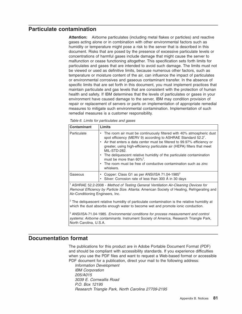
Particulate contaminationAttention: Airborne particulates (including metal flakes or particles) and reactivegases acting alone or in combination with other environmental factors such ashumidity or temperature might pose a risk to the server that is described in thisdocument. Risks that are posed by the presence of excessive particulate levels orconcentrations of harmful gases include damage that might cause the server tomalfunction or cease functioning altogether. This specification sets forth limits forparticulates and gases that are intended to avoid such damage. The limits must notbe viewed or used as definitive limits, because numerous other factors, such astemperature or moisture content of the air, can influence the impact of particulatesor environmental corrosives and gaseous contaminant transfer. In the absence ofspecific limits that are set forth in this document, you must implement practices thatmaintain particulate and gas levels that are consistent with the protection of humanhealth and safety. If IBM determines that the levels of particulates or gases in yourenvironment have caused damage to the server, IBM may condition provision ofrepair or replacement of servers or parts on implementation of appropriate remedialmeasures to mitigate such environmental contamination. Implementation of suchremedial measures is a customer responsibility.
Table 6. Limits for particulates and gases
Contaminant Limits
Particulate v The room air must be continuously filtered with 40% atmospheric dustspot efficiency (MERV 9) according to ASHRAE Standard 52.21.
v Air that enters a data center must be filtered to 99.97% efficiency orgreater, using high-efficiency particulate air (HEPA) filters that meetMIL-STD-282.
v The deliquescent relative humidity of the particulate contaminationmust be more than 60%2.
v The room must be free of conductive contamination such as zincwhiskers.
Gaseous v Copper: Class G1 as per ANSI/ISA 71.04-19853
v Silver: Corrosion rate of less than 300 Å in 30 days1 ASHRAE 52.2-2008 - Method of Testing General Ventilation Air-Cleaning Devices forRemoval Efficiency by Particle Size. Atlanta: American Society of Heating, Refrigerating andAir-Conditioning Engineers, Inc.
2 The deliquescent relative humidity of particulate contamination is the relative humidity atwhich the dust absorbs enough water to become wet and promote ionic conduction.
3 ANSI/ISA-71.04-1985. Environmental conditions for process measurement and controlsystems: Airborne contaminants. Instrument Society of America, Research Triangle Park,North Carolina, U.S.A.
Documentation formatThe publications for this product are in Adobe Portable Document Format (PDF)and should be compliant with accessibility standards. If you experience difficultieswhen you use the PDF files and want to request a Web-based format or accessiblePDF document for a publication, direct your mail to the following address:
Information DevelopmentIBM Corporation205/A0153039 E. Cornwallis RoadP.O. Box 12195Research Triangle Park, North Carolina 27709-2195
Appendix B. Notices 81

U.S.A.
In the request, be sure to include the publication part number and title.
When you send information to IBM, you grant IBM a nonexclusive right to use ordistribute the information in any way it believes appropriate without incurring anyobligation to you.
Telecommunication regulatory statementThis product is not intended to be connected directly or indirectly by any meanswhatsoever to interfaces of public telecommunications networks, nor is it intendedto be used in a public services network.
Electronic emission noticesWhen you attach a monitor to the equipment, you must use the designated monitorcable and any interference suppression devices that are supplied with the monitor.
Federal Communications Commission (FCC) statementNote: This equipment has been tested and found to comply with the limits for aClass A digital device, pursuant to Part 15 of the FCC Rules. These limits aredesigned to provide reasonable protection against harmful interference when theequipment is operated in a commercial environment. This equipment generates,uses, and can radiate radio frequency energy and, if not installed and used inaccordance with the instruction manual, may cause harmful interference to radiocommunications. Operation of this equipment in a residential area is likely to causeharmful interference, in which case the user will be required to correct theinterference at his own expense.
Properly shielded and grounded cables and connectors must be used in order tomeet FCC emission limits. IBM is not responsible for any radio or televisioninterference caused by using other than recommended cables and connectors or byunauthorized changes or modifications to this equipment. Unauthorized changes ormodifications could void the user's authority to operate the equipment.
This device complies with Part 15 of the FCC Rules. Operation is subject to thefollowing two conditions: (1) this device may not cause harmful interference, and (2)this device must accept any interference received, including interference that maycause undesired operation.
Industry Canada Class A emission compliance statementThis Class A digital apparatus complies with Canadian ICES-003.
Avis de conformité à la réglementation d'Industrie CanadaCet appareil numérique de la classe A est conforme à la norme NMB-003 duCanada.
Australia and New Zealand Class A statementAttention: This is a Class A product. In a domestic environment this product maycause radio interference in which case the user may be required to take adequatemeasures.
82 System x iDataPlex dx360 M3: User's Guide

European Union EMC Directive conformance statementThis product is in conformity with the protection requirements of EU CouncilDirective 2004/108/EC on the approximation of the laws of the Member Statesrelating to electromagnetic compatibility. IBM cannot accept responsibility for anyfailure to satisfy the protection requirements resulting from a nonrecommendedmodification of the product, including the fitting of non-IBM option cards.
Attention: This is an EN 55022 Class A product. In a domestic environment thisproduct may cause radio interference in which case the user may be required totake adequate measures.
Responsible manufacturer:International Business Machines Corp.New Orchard RoadArmonk, New York 10504914-499-1900
European Community contact:IBM Technical Regulations, Department M456IBM-Allee 1, 71137 Ehningen, GermanyTelephone: 0049 (0) 7032 15-2937E-mail: [email protected]
Germany Class A statementDeutschsprachiger EU Hinweis:
Hinweis für Geräte der Klasse A EU-Richtlinie zur ElektromagnetischenVerträglichkeit
Dieses Produkt entspricht den Schutzanforderungen der EU-Richtlinie 2004/108/EGzur Angleichung der Rechtsvorschriften über die elektromagnetische Verträglichkeitin den EU-Mitgliedsstaaten und hält die Grenzwerte der EN 55022 Klasse A ein.
Um dieses sicherzustellen, sind die Geräte wie in den Handbüchern beschrieben zuinstallieren und zu betreiben. Des Weiteren dürfen auch nur von der IBMempfohlene Kabel angeschlossen werden. IBM übernimmt keine Verantwortung fürdie Einhaltung der Schutzanforderungen, wenn das Produkt ohne Zustimmung derIBM verändert bzw. wenn Erweiterungskomponenten von Fremdherstellern ohneEmpfehlung der IBM gesteckt/eingebaut werden.
EN 55022 Klasse A Geräte müssen mit folgendem Warnhinweis versehen werden:“Warnung: Dieses ist eine Einrichtung der Klasse A. Diese Einrichtung kann imWohnbereich Funk-Störungen verursachen; in diesem Fall kann vom Betreiberverlangt werden, angemessene Maßnahmen zu ergreifen und dafür aufzukommen.”
Deutschland: Einhaltung des Gesetzes über dieelektromagnetische Verträglichkeit von GerätenDieses Produkt entspricht dem “Gesetz über die elektromagnetische Verträglichkeitvon Geräten (EMVG)”. Dies ist die Umsetzung der EU-Richtlinie 2004/108/EG inder Bundesrepublik Deutschland.
Appendix B. Notices 83

Zulassungsbescheinigung laut dem Deutschen Gesetz über dieelektromagnetische Verträglichkeit von Geräten (EMVG) (bzw. derEMC EG Richtlinie 2004/108/EG) für Geräte der Klasse ADieses Gerät ist berechtigt, in Übereinstimmung mit dem Deutschen EMVG dasEG-Konformitätszeichen - CE - zu führen.
Verantwortlich für die Einhaltung der EMV Vorschriften ist der Hersteller:International Business Machines Corp.New Orchard RoadArmonk, New York 10504914-499-1900
Der verantwortliche Ansprechpartner des Herstellers in der EU ist:IBM DeutschlandTechnical Regulations, Department M456IBM-Allee 1, 71137 Ehningen, GermanyTelephone: 0049 (0) 7032 15-2937E-mail: [email protected]
Generelle Informationen:
Das Gerät erfüllt die Schutzanforderungen nach EN 55024 und EN 55022Klasse A.
Japan VCCI Class A statement
This is a Class A product based on the standard of the Voluntary Control Council forInterference (VCCI). If this equipment is used in a domestic environment, radiointerference may occur, in which case the user may be required to take correctiveactions.
Japan Electronics and Information Technology Industries Association(JEITA) statement
jjieta
1
Japanese Electronics and Information Technology Industries Association (JEITA)Confirmed Harmonics Guideline (products less than or equal to 20 A per phase)
Korea Communications Commission (KCC) statement
84 System x iDataPlex dx360 M3: User's Guide

Please note that this equipment has obtained EMC registration for commercial use.In the event that it has been mistakenly sold or purchased, please exchange it forequipment certified for home use.
Russia Electromagnetic Interference (EMI) Class A statement
ruse
mi
People's Republic of China Class A electronic emission statement
Taiwan Class A compliance statement
Appendix B. Notices 85

86 System x iDataPlex dx360 M3: User's Guide

Index
Numerics2U chassis
removing expansion enclosure 29removing system-board tray 29
3U chassisinstalling 58removing 28removing system-board tray 30
Aaccessible documentation 81adapter
connector locations 35features 7installing 35, 43
administrator password 66assistance, getting 77attention notices 4availability 9
Bblue-screen capture 8blue-screen capture feature
overview 69boot manager 67
Ccable connection 59caution statements 4chassis features 17Class A electronic emission notice 82components
chassis 17system board 15system-board tray 14
configuration programs 61configuring
Ethernet controller 71integrated management module settings 71RAID 72
connecting cables 59connectors 21, 23
memory 15microprocessor 15SATA hard disk drives 15system board 15
contamination, particulate and gaseous 81controls 21creating a mirrored pair of hard disk drives 73
Ddanger statements 4device drivers 10DIMMs
connector locations 49installing 48memory mirroring 49order of installation 49
documentation CD 3documentation format 81drive
connectors 15specifcations 8
Eelectronic emission Class A notice 82Ethernet 7, 8Ethernet connector 22Ethernet controller, configuring 71Ethernet transmit/receive activity LED 22expansion enclosure
installing 54removing 29, 32
FFCC Class A notice 82features and specifications
electrical input 5environment 5expansion slots 5hard disk drives 5integrated management module 5memory 5microprocessor 5server 5size 5
firmware update 74formatting a hard disk drive 73
Ggaseous contamination 81getting help 77
Hhard disk drive
activity LED 22installing
2.5-inch hot-swap 462.5-inch simple-swap 473.5-inch hot-swap 453.5-inch simple-swap 45
© Copyright IBM Corp. 2011 87

hard disk drive (continued)removing
2.5-inch hot-swap 342.5-inch simple-swap 353.5-inch hot-swap 333.5-inch simple-swap 33
specifications 6hardware service and support 78help, getting 77
IIBM Support Line 78IBM Systems Director 10, 75iDataPlex rack
installing 3U chassis 58removing 3U chassis 28
important notices 4installation guidelines 26installing
2.5-inch simple-swap solid-state drive 473U chassis 58adapter 35expansion enclosure 54hard disk drive
2.5-inch hot-swap 462.5-inch simple-swap 473.5-inch hot-swap 453.5-inch simple-swap 45
memory module 48PCI adapter 43PCI riser card 44system-board tray 55, 56system-board tray cover 53virtual media key 52
integrated functions 6integrated management module
configuration 71description 7
introduction 1IP address
obtaining for web-based interface access 70
Jjumpers
system board 16
LLEDs 21link LED 22local area network (LAN) 7Locator (location) LED 22LSI Logic Configuration Utility program 72
starting 73
Mmemory module
connector locations 49installing 48memory mirroring 48online-spare memory 48specifications 6
microprocessorconnector location 15specifications 6
Nnotes 4notes, important 80notices 79
electronic emission 82FCC, Class A 82
notices and statements 4
Oobtaining
the IP address for web-based interface access 70operating system 25overview 7
Pparticulate contamination 81password 66
administrator 66power-on 66
PCIconnector locations 35expansion slots 6installing 35
PCI adapterinstalling 43
PCI riser cardinstalling 44
power LED 22power-control button 21power-cord connector 23power-on password 66public services network, use in 82public telecommunications network, connection to 82publications 2
RRAID configuration 72RAS features 9reliability 9remote presence capability 8remote presence feature
using 69removing
2.5-inch simple-swap solid-state drive 353U chassis 28
88 System x iDataPlex dx360 M3: User's Guide
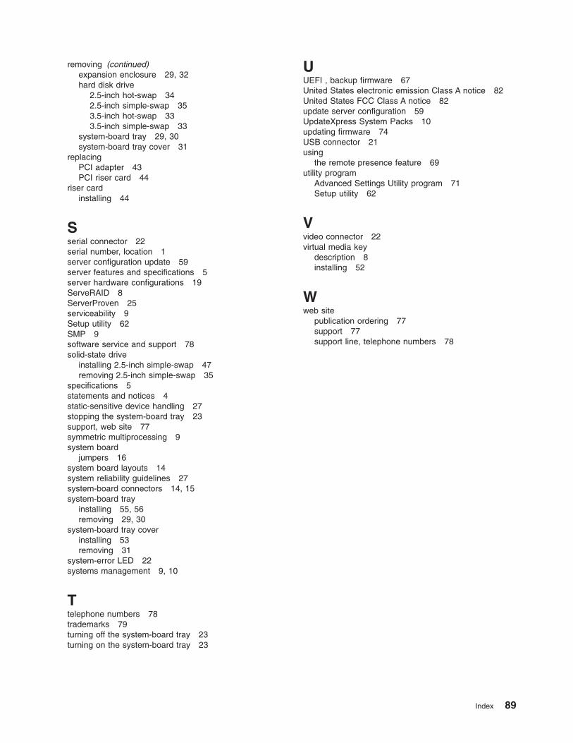
removing (continued)expansion enclosure 29, 32hard disk drive
2.5-inch hot-swap 342.5-inch simple-swap 353.5-inch hot-swap 333.5-inch simple-swap 33
system-board tray 29, 30system-board tray cover 31
replacingPCI adapter 43PCI riser card 44
riser cardinstalling 44
Sserial connector 22serial number, location 1server configuration update 59server features and specifications 5server hardware configurations 19ServeRAID 8ServerProven 25serviceability 9Setup utility 62SMP 9software service and support 78solid-state drive
installing 2.5-inch simple-swap 47removing 2.5-inch simple-swap 35
specifications 5statements and notices 4static-sensitive device handling 27stopping the system-board tray 23support, web site 77symmetric multiprocessing 9system board
jumpers 16system board layouts 14system reliability guidelines 27system-board connectors 14, 15system-board tray
installing 55, 56removing 29, 30
system-board tray coverinstalling 53removing 31
system-error LED 22systems management 9, 10
Ttelephone numbers 78trademarks 79turning off the system-board tray 23turning on the system-board tray 23
UUEFI , backup firmware 67United States electronic emission Class A notice 82United States FCC Class A notice 82update server configuration 59UpdateXpress System Packs 10updating firmware 74USB connector 21using
the remote presence feature 69utility program
Advanced Settings Utility program 71Setup utility 62
Vvideo connector 22virtual media key
description 8installing 52
Wweb site
publication ordering 77support 77support line, telephone numbers 78
Index 89

90 System x iDataPlex dx360 M3: User's Guide


����
Part Number: 00D3152
Printed in USA
(1P) P/N: 00D3152


![carmen don.ppt [Read-Only] · CH1:1. CH1:2. CH1:3. CH1:4 DREDGING UFGS SECTION 02325. CH1:5 HOW IT STARTED Corps Spec Steering Committee: Need Suggested Queried Districts Districts:](https://img.dokumen.tips/doc/110x75/5f13e2ca0b294765f40b232e/carmen-donppt-read-only-ch11-ch12-ch13-ch14-dredging-ufgs-section-02325.jpg)