Embed Size (px)
Citation preview
June 2003, ver. 1.1 Application Note 299
System Development Toolsfor Excalibur Devices
Introduction The Excalibur™ devices achieve a new level of system integration from the inclusion of an embedded processor system within a field programmable gate array (FPGA). Such an integration increases the demands placed on the system development tools and the resulting programming files. To utilize the Excalibur devices fully, both programmable logic development tools and embedded software development tools are used. This document describes the flow of the system development tools for generating programmable logic configuration files and the embedded processor software files to create a single system-level device programming file.
An Excalibur-based system contains three sections:
■ The digital logic design of the FPGA■ The embedded software application running on the processor■ The parameterization and instantiation of the embedded processor
stripe
On power-up, Excalibur devices can either be viewed as an embedded processor within an FPGA, or as an FPGA within an embedded processor. As an embedded processor, the development tool flow facilitates the creation and downloading of a single system file containing both the configuration of the FPGA logic and the embedded software, in an appropriate format for storing in an external flash memory device. In this mode, the embedded stripe parameters are integrated into the boot section of the embedded software application. As an FPGA, the development tool flow facilitates the creation of a single system file containing all three sections. The file formats provided are standard FPGA configurations file to be stored in an external configuration device, such as an EPC2 serial EPROM.
Altera Corporation 1
AN-299-1.1

AN 299: System Development Tools for Excalibur Devices
FPGA Logic Design
The development of digital logic for the programmable logic section of the devices follows the same flow as any other design for an Altera® APEX™ device. The FPGA designs are provided in either VHDL or Verilog hardware descriptions languages (HDL). The creation of this HDL can be through tools such as Altera’s SOPC Builder, provided by third parties in the form of IP cores, or created by the user in a text editor. The HDL must be synthesized into a form that can be placed and routed by the Quartus® II development tools. Typically, the Altera Quartus II development tools are used in conjunction hardware simulation tools from Altera or a third party partner. A variety of simulation models are provided, which can be used to model the device behavior at varying levels of detail.
Embedded Software Design
The development of embedded software for the embedded processor section follows the same flow as any other embedded software design for an ARM processor. Altera provides GNUPro compilation and debug tools for embedded software development with Quartus II software subscriptions. With the use of SOPC Builder, a graphical user interface-based system design tool, all necessarry header and configuration files are generated automatically.
Parameterization and Instantiation of the Embedded Processor Stripe
The Altera MegaWizard® Plug-in Manager (a graphical user interface utility) provides the designers the ability to set the operational parameters for the embedded processor. The MegaWizard Plug-In outputs a system build descriptor file (.sbd), which describes the set-up of the device, including the following characteristics:
■ Device booting—from an external flash device or an external FPGA configuration device
■ Processor endian-ness ■ Device memory map ■ Use of the bridges between the stripe and the PLD■ configuration of integrated peripherals (timers, UART, SDRAM, EBI) ■ Peripheral input-voltage levels ■ Peripheral output configurations ■ Frequency of operation (settings for the PLLs) for the processor and
the SDRAM controller
2 Altera Corporation

AN 299: System Development Tools for Excalibur Devices
The .sbd file produced by the MegaWizard Plug-In is used in both the hardware and software design flows.
In addition to parameterization of the embedded stripe, the MegaWizard Plug-In produces files used in the FPGA logic design and verification, as well as instantiating simulation models for the hardware and software co-simulation. The files produced are the following:
■ .v or .vhd files containing instantiations of the embedded processor and dual-port RAM blocks and header files, as follows:– for Verilog files, module instance containing stripe structural
code, plus an include file– for VHDL files, entity instance containing stripe structural code,
plus .vhd package, plus additional template component declaration (VHDL 1987 only)
■ A ‘C’ language header file, containing definitions of the memory map■ an assembly language header file, containing definitions of the
memory map■ A block symbol file, needed for instantiation in a Quartus II software
Block Design File
Whenever the MegaWizard Plug-In updates the .sbd file, it automatically recreates these files.
Figure 1 shows the MegaWizard Plug-In process. After running the MegaWizard Plug-In, the system development flow varies slightly, based on the method of configuration. The remainder of this document describes the flow for creating system files for configuring the devices as a processor, followed by configuring the device as an FPGA.
Altera Corporation 3

AN 299: System Development Tools for Excalibur Devices
Figure 1. MegaWizard Plug-In Process
Booting from Flash Via the Altera Bootloader
Altera provides a bootloader for use when booting from external flash memory. The bootloader initializes the device registers according to the MegaWizard Plug-In output, including setting up the memory map of the device; and then loads the software into RAM. It resets the watchdog timer and finally sets the endian-ness of the processor, before passing control to the user’s code.
Figure 2 shows the toolflow for configuration from flash memory.
Excalibur MegaWizard
Plug-in
HDL/H Generator
GUI
System Build Descriptor File
(.sbd)
C/C++ Header File (.h)
HDL Template
Stripe Declaration File and Header File
(.v or .vhd)
Block Symbol File
(.bsf)
4 Altera Corporation

AN 299: System Development Tools for Excalibur Devices
Figure 2. Configuration from Flash
Excalibur MegaWizard
Plug-in
.h
SOPC Builder
(optional)
Hardware Design Entry
.hexout
HDL Template
Synthesize (after satisfactory
simulation)
Filter
.sbi
Intel .hex
.o Loader Library
Link and convert object file to .hex
MakeProgFile
.h, .c, .ccc
Software Design Entry
Software Build Environment
.v or .vhd chip
design
.edf
.v or .vhd stripe
declaration
System Build
Descriptor File (.sbd)
Altera Corporation 5

AN 299: System Development Tools for Excalibur Devices
When a device is configured using the Altera flash bootloader, the required output at the end of a successful design compilation is an Intel .hex file.
To run a hardware compilation and produce a .hex file for configuring a device from flash memory, proceed as follows.
1. Run the Excalibur MegaWizard Plug-In to configure the embedded logic.
2. Create an Intel .hex file for the software image using either the compiler/linker provided with the Quartus II software in software mode or a preferred utility.
1 Sample startup code for Excalibur is provided with the EPXA10 or EPXA1 Development Board Getting Started User Guides available on www.altera.com. The code provides examples of initializing stack pointers, setting up interrupt handlers, enabling caches and MMU, and linking to C runtime libraries.
f See the “Hello World” design file descriptions in the user guides to find the specific file containing the example code.
If the .hex file does not contain an entry point, it is assumed to be the first address in the .hex file.
The ARM FromElf utility does not specify an entry point in the .hex file, even if it is non-zero, so the first address is always used.
3. Use the Quartus II software to compile the design, generating a slave binary image (.sbi) file.
4. Use the MakeProgFile command-line utility to merge the .hex file, the .sbd file, and the .sbi PLD image into an object file.
Makeprogfile, one of the Excalibur utilities, is an application that allows you to create programming files and generate memory initialization files. Other Excalibur utilities allow you to set up the programming hardware, and download applications to flash memory.
f See “Excalibur Device Utilities” on page 11 for additional details on the these Utilities.
6 Altera Corporation
AN 299: System Development Tools for Excalibur Devices
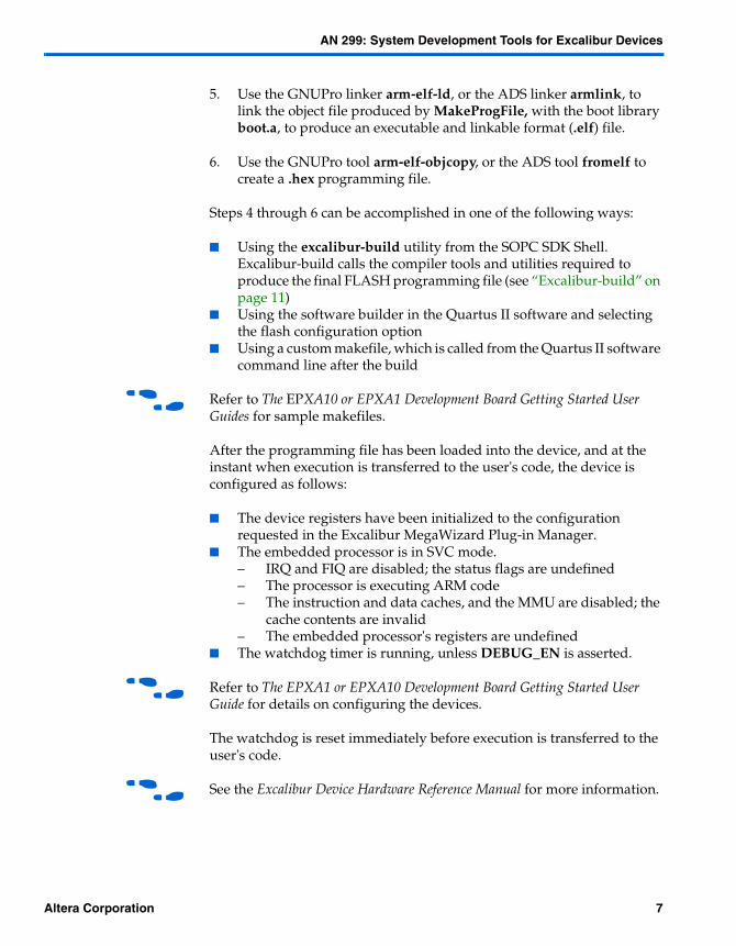
5. Use the GNUPro linker arm-elf-ld, or the ADS linker armlink, to link the object file produced by MakeProgFile, with the boot library boot.a, to produce an executable and linkable format (.elf) file.
6. Use the GNUPro tool arm-elf-objcopy, or the ADS tool fromelf to create a .hex programming file.
Steps 4 through 6 can be accomplished in one of the following ways:
■ Using the excalibur-build utility from the SOPC SDK Shell. Excalibur-build calls the compiler tools and utilities required to produce the final FLASH programming file (see “Excalibur-build” on page 11)
■ Using the software builder in the Quartus II software and selecting the flash configuration option
■ Using a custom makefile, which is called from the Quartus II software command line after the build
f Refer to The EPXA10 or EPXA1 Development Board Getting Started User Guides for sample makefiles.
After the programming file has been loaded into the device, and at the instant when execution is transferred to the user's code, the device is configured as follows:
■ The device registers have been initialized to the configuration requested in the Excalibur MegaWizard Plug-in Manager.
■ The embedded processor is in SVC mode.– IRQ and FIQ are disabled; the status flags are undefined– The processor is executing ARM code– The instruction and data caches, and the MMU are disabled; the
cache contents are invalid– The embedded processor's registers are undefined
■ The watchdog timer is running, unless DEBUG_EN is asserted.
f Refer to The EPXA1 or EPXA10 Development Board Getting Started User Guide for details on configuring the devices.
The watchdog is reset immediately before execution is transferred to the user's code.
f See the Excalibur Device Hardware Reference Manual for more information.
Altera Corporation 7

AN 299: System Development Tools for Excalibur Devices
Configuration from an External Source
Figure 3 shows the sequence of tool use for configuration from an external configuration device, via passive configuration schemes.
Figure 3. Passive-Serial or Passive-Parallel Configuration Schemes
Excalibur MegaWizard
Plug-in
.h
SOPC Builder
(optional)
Hardware Design Entry
HDL Template
Synthesize (after satisfactory
simulation)
Filter
.sbi
Intel .hex
.pof, .sof
MakeProgFile
.h, .c, .ccc
Software Design Entry
Software Build Environment
.v or .vhd chip
design
.edf
.v or .vhd stripe
declaration
System Build
Descriptor File (.sbd)
8 Altera Corporation

AN 299: System Development Tools for Excalibur Devices
When a device is configured using a passive-serial or passive-parallel configuration scheme, the required output at the end of a successful hardware compilation is one or more of the following file types.
■ .pof■ .sof■ .rbf■ .ttf■ .hexout
The following steps explain how to create a programming file of the hardware design.
1. Run the Excalibur MegaWizard Plug-in to configure the embedded logic.
2. Create and synthesize the RTL, using either the Quartus II software or third-party hardware development tools.
3. Specify a software image (in Intel .hex format) to be merged into the programming file at the fitting stage.
The Quartus II software always produces a .pof and a .sof file. Optionally, .rbf, .ttf, and .hexout files are also produced.
The following steps explain how to generate a configuration file for the software design.
1. Create an Intel .hex file for the software image using either the compiler/linker provided with the Quartus II software in software mode, or a preferred utility.
If the .hex file does not specify an entry point, it is assumed to be the first address in the .hex file.
1 The ARM FromElf utility does not specify an entry point in the .hex file, even if it is non-zero, so the first address is always used.
2. Use the Quartus II MakeProgFile command-line utility to merge the .hex file, the .sbd file, and the partial SRAM object file (.psof) PLD image into the appropriate types of programming file.
Altera Corporation 9

AN 299: System Development Tools for Excalibur Devices
Makeprogfile, one of the Excalibur utilities, is an application that allows you to create programming files and generate memory initialization files. Other Excalibur utilities allow you to set up the programming hardware and download applications to flash memory.
f See “Excalibur Device Utilities” on page 11 for additional details on the Excalibur Utilities.
You can also use Quartus II software mode, to generate the programming file. Specify the .psof PLD image to be merged with the .hex file and the Quartus II software then produces .pof, .sof, .rbf, and .ttf files.
After the programming file has been loaded into the device, and at the instant when execution is transferred to the user's code, the device is configured as follows:
■ The device registers have been initialized to the configuration requested in the Excalibur MegaWizard Plug-in Manager.
■ If no application has been loaded, the processor is held in reset; if an application is present, the processor is released from reset, with the following characteristics.– the embedded processor is in SVC mode– IRQ and FIQ are disabled; the status flags are undefined– the processor is executing ARM code– the instruction and data caches, and the MMU are disabled; the
cache contents are invalid– the embedded processor's registers are undefined
■ The watchdog timer is running, unless DEBUG_EN is asserted.
f Refer to The EPXA1 or EPXA10 Development Board Getting Started User Guide for details on configuring the devices.
f See the Excalibur Device Hardware Reference Manual for more information.
10 Altera Corporation

AN 299: System Development Tools for Excalibur Devices
Excalibur Device Utilities
This section presents descriptions and usage guidelines for the Excalibur device utilities: excalibur-build, makeprogfile, exc_ flash_programmer, jtagconfig, memimagedecoder. The excalibur-build utiliy is installed with the GNU Tools and Excalibur Component—the other utilities are installed automatically when you install the Quartus II software. If you do not need to modify the hardware portions of the design and do not require the full installation of the Quartus II software, you can install just the utilities via the Quartus II custom installation options.
Excalibur-build
The excalibur-build utility is a simple alternative to a makefile and provide a quick method of building applications for the Excalibur device. The use of makefiles is fully supported for complex applications.
The excalibur-build utility invokes the tools need to compile, assemble and link source code targeted to the Excalibur Device. It insures the standard C libraries and standard Excalibur Libraries are linked with the user source code and the associated “include” paths are available. Most programs will compile with no command line options; reasonable defaults are assumed.
f For an example makefile targeted to the Excalibur Device, refer to the EPXA1 Getting Started User Guide.
1 Excalibur-build must be launched from SOPC Builder bash shell.
Excalibur-build produces a file with the base name of the last source file on the command line and the suffix _flash.hex. The file is ready for downloading to flash on EBI0 on the target board.
Source files are listed on the command line following the options. If only one source file is specified, excalibur-build searches the current directory for files with the same base name and underscore extensions.
Usage
The excalibur-build utility has the following syntax
excalibur-build [options] <sourcefiles.[c]>
Altera Corporation 11

AN 299: System Development Tools for Excalibur Devices
Table 1 shows the excalibur-build utilty options.
Examples
Multiple files listed in the following command line generate the flash .hex file bar_flash.hex:
excalibur-build foo.c bar.c
If the files helloworld_2.c and helloworld_3.c are in the same directory, type the following command to include them in the build and give helloworld_flash.hex:
excalibur-build helloworld.c
Makeprogfile
The makeprogfile utility is a command line utility that merges the hardware logic image with the software application to generate a boot data file, serial programming files, or simulation model initialization files.
Usage
[-h/--help] Displays help message
[-v/--version] Displays version of makeprogfile
{passive programming file options} <project>.sbd [<filename>.psof] [<file>.hex]
Table 1. excalibur-build Utility Options
Options Description
–cc <quoted string> Pass command line options to the compiler.
–ld <quoted string> Pass command line options to the linker.
–S Silent mode (only prints errors).
–l <filename> Include system library.
–o <filename> Output filename.
–O0 <filename> Compile with no optimizations.
–O1 <filename> Compile with some optimizations.
–O2 <filename> Compile with more optimizations.
–help Prints help.
–help1 Prints more help.
12 Altera Corporation

AN 299: System Development Tools for Excalibur Devices
{flash programming file options} <project>.sbd [<filename>.sbi] [<file>.hex]
{simulation init file options} <project>.sbd [<file>.hex]
Passive programming file options are:
-e/--serial-eprom <EPC2/EPC4/EPC8/EP16>
[-s/--sof <filename>.sof] Generates .SOF file
[-p/--pof <filename>.pof] Generates .POF file(s)
[-r/--rbf <filename>.rbf] Generates .RBF file
[-t/--ttf <filename>.ttf] Generates .TTF file
[-x/--hexout <filename>.hexout]Generates .HEXOUT file
[-a/--hexout-addr <address>] Specifies start address for .HEXOUT
Flash programming file options are:
-b/--bootdata <filename>.o
-nc/--no-compression Suppress the compression of preload data
Simulation initialization file options are:
-m/--model-init <basename> Base name of model initialization files
If the target system is to operate in boot-from-flash mode, you can use the makeprogfile utility to create a boot data file.
If you specify a Slave Binary Image File (.sbi) as an input file on the command line, the bootloader configures the programmable logic device using the data from that .sbi file.
If the target system is to operate in boot-from-serial mode, the makeprogfile utility is used to generate any Programmer Object Files (.pof), SRAM Object Files (.sof) Raw Binary Files (.rbf), Tabular Text Files (.ttf), or Hexadecimal (Intel-Format) Output Files (.hexout) that you specify.
Altera Corporation 13

AN 299: System Development Tools for Excalibur Devices
In boot-from-serial mode, the memory initialization data from the hexadecimal (Intel-Format) file(s) (.hex) that you specify as input file(s) is merged with the programmable logic Partial SRAM Object File (.psof) that was generated by the Quartus II Compiler when you compiled a hardware design. This produces the configuration bitstream, which is ouput as .pof, .sof, .rbf, .ttf and/or .hexout files. You must specify the type of serial EEPROM you are going to use, using the --serial-eprom command-line option.
You can also use the makeprogfile utility to generate initialization files for the Excalibur embedded processor stripe simulation model, using the --model-init <basename> command-line option.
When the makeprogfile utility is used to generate simulation model initialization files, the --model-init <basename> command-line option described below specifies the non-extension part of each file name. For example, the simtest part of simtest.dpram0. The extension of each simulation model initialization file name is provided by the makeprogfile utility.
The makeprogfile utility reads information from the files you specify, and writes any output files that you specify with the command-line options.
A System Build Descriptor file (.sbd), specified with the Excalibur MegaWizard Plug-In is used by the makeprogfile utility to generate register writes to set up the stripe. If hexadecimal (Intel-format) files (.hex) are specified as input files for memory initialization, the SRAM, DPSRAM and/or SDRAM is initialized using the hexadecimal file contents. Addresses in .hex files are interpreted as physical addresses.
Exc_flash_programmer
The exc_ flash_programmer utility is a stand-alone command line utility for programming flash connected to the expansion bus interface of the EPXA devices. The utility uses the ByteBlaster™ download cable via the JTAG interface. Version 2.2 of the flash programmer supports 16-bit flash devices, which are compatible with either the Intel 28FXX0C3 (primary OEM command set 0003) or the AMD AM29DL32XD (primary OEM command set 0002) advanced boot-block families.
f For more information on the Excalibur Flash Programmer and supported devices, refer to Application Note 143: Using the Expansion Bus Interface.
Usage:
exc_flash_programmer {options} <hexfile.hex>
14 Altera Corporation
AN 299: System Development Tools for Excalibur Devices
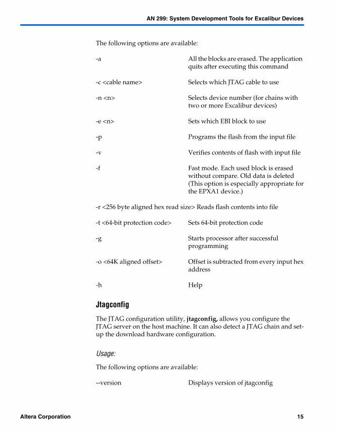
The following options are available:
-a All the blocks are erased. The application quits after executing this command
-c <cable name> Selects which JTAG cable to use
-n <n> Selects device number (for chains withtwo or more Excalibur devices)
-e <n> Sets which EBI block to use
-p Programs the flash from the input file
-v Verifies contents of flash with input file
-f Fast mode. Each used block is erasedwithout compare. Old data is deleted(This option is especially appropriate forthe EPXA1 device.)
-r <256 byte aligned hex read size> Reads flash contents into file
-t <64-bit protection code> Sets 64-bit protection code
-g Starts processor after successfulprogramming
-o <64K aligned offset> Offset is subtracted from every input hexaddress
-h Help
Jtagconfig
The JTAG configuration utility, jtagconfig, allows you configure the JTAG server on the host machine. It can also detect a JTAG chain and set-up the download hardware configuration.
Usage:
The following options are available:
--version Displays version of jtagconfig
Altera Corporation 15

AN 299: System Development Tools for Excalibur Devices
--enum Enumerates devices present in the JTAGchain attached to the hardware. Names of devices are indicated for known devices.
For example, with a ByteBlaster download cable present on LPT1 and other devices in the JTAG chain, typing jtagconfig <return> generates the following output:
1. ByteBlaster on LPT1090010DD EPXA10049220DD EPXA-ARM®92204000102 !090000DD ! EP20K1000E04056102 ! 010020DD EPC2010020DD EPC2010020DD EPC2
2. MasterBlaster on COM2Unable to lock chain (hardware not attached)
Devices that cannot be used because the jtagconfig utility does not have enough data for the JTAG chain, are indicated with an exclamation mark. Although the EP20K1000E above has been recognized, it cannot be used because the jtagconfig utility does not recognize devices on either side of it.
--add <type> <port> Tells the JTAG server that the specifiedhardware type is attached to thespecified port. USB devices are auto-detected and therefore do not needto be added using the jtagconfig utility.
For example, typing --add byteblaster LPT1, or --add masterblaster com2, adds the specified devices to the JTAG chain.
--remove <id> Removes the hardware specified by theID number.
The ID is the listed number of the device after typing jtagconfig --enum. In the example above, ByteBlaster is listed as device 1, and MasterBlaster™ cable as device 2. Thus, typing jtagconfig --remove 2, would remove the MasterBlaster cable from the JTAG chain.
--help Displays help message
16 Altera Corporation

AN 299: System Development Tools for Excalibur Devices
Memimagedecoder
Memimagedecoder is a command line utility that retrieves the Excalibur embedded processor stripe initialization data from an SRAM object file (.sof), and boot data from the boot data file <project name>_bootdata.o respectively. Memimagedecoder then displays the data in readable format to allow the code to be examined.
Usage:
memimagedecoder [-h/--help/] Displays help message
memimagedecoder[-v/--version]Displays the version of memimagedecoder
memimagedecoder <filename>.sof [output-option] Load Excalibur stripe initialization data
from an SOF and output the data ina readable format.
memimagedecoder <filename>o [output-option] Load Excalibur stripe
initialization data from abootdata object file andoutput the data in a readableformat.
The following output option is available. When the output option is not specified, all the data interpreted from the input file is displayed in the command window.
-o/--output filename Output file
Altera Corporation 17

AN 299: System Development Tools for Excalibur Devices
101 Innovation DriveSan Jose, CA 95134(408) 544-7000http://www.altera.comApplications Hotline:(800) 800-EPLDLiterature Services:[email protected]
Copyright 2003 Altera Corporation. Altera, The Programmable Solutions Company, the stylized Altera logo,specific device designations, and all other words and logos that are identified as trademarks and/or servicemarks are, unless noted otherwise, the trademarks and service marks of Altera Corporation in the U.S. andother countries. All other product or service names are the property of their respective holders. Altera productsare protected under numerous U.S. and foreign patents and pending applications, maskwork rights, andcopyrights. Altera warrants performance of its semiconductor products to currentspecifications in accordance with Altera’s standard warranty, but reserves the right tomake changes to any products and services at any time without notice. Altera assumes noresponsibility or liability arising out of the application or use of any information, product,or service described herein except as expressly agreed to in writing by Altera Corporation.Altera customers are advised to obtain the latest version of device specifications beforerelying on any published information and before placing orders for products or services.All rights reserved.
18 Altera Corporation