Embed Size (px)
Citation preview
ExcaliburOperator’s Manual
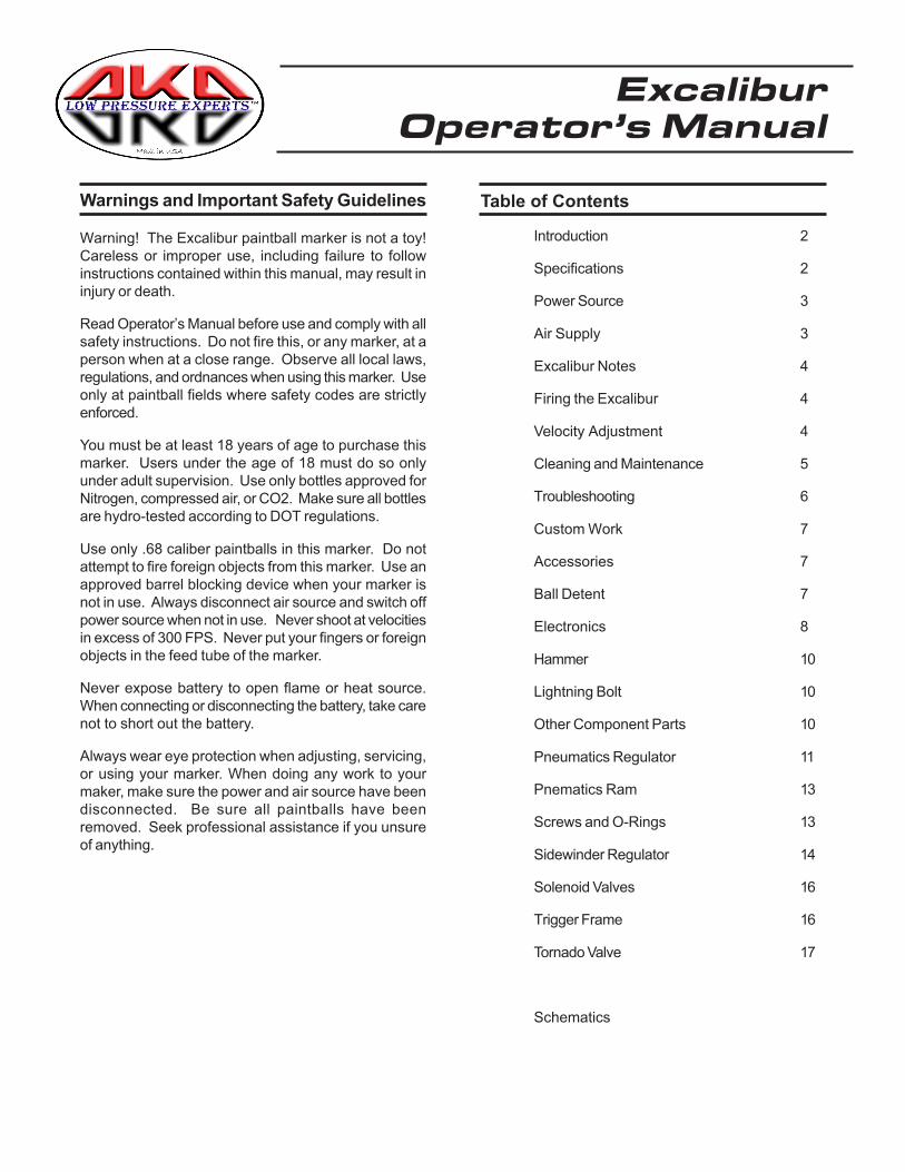
Table of Contents
Introduction 2
Specifications 2
Power Source 3
Air Supply 3
Excalibur Notes 4
Firing the Excalibur 4
Velocity Adjustment 4
Cleaning and Maintenance 5
Troubleshooting 6
Custom Work 7
Accessories 7
Ball Detent 7
Electronics 8
Hammer 10
Lightning Bolt 10
Other Component Parts 10
Pneumatics Regulator 11
Pnematics Ram 13
Screws and O-Rings 13
Sidewinder Regulator 14
Solenoid Valves 16
Trigger Frame 16
Tornado Valve 17
Schematics
Warnings and Important Safety Guidelines
Warning! The Excalibur paintball marker is not a toy!Careless or improper use, including failure to followinstructions contained within this manual, may result ininjury or death.
Read Operator’s Manual before use and comply with allsafety instructions. Do not fire this, or any marker, at aperson when at a close range. Observe all local laws,regulations, and ordnances when using this marker. Useonly at paintball fields where safety codes are strictlyenforced.
You must be at least 18 years of age to purchase thismarker. Users under the age of 18 must do so onlyunder adult supervision. Use only bottles approved forNitrogen, compressed air, or CO2. Make sure all bottlesare hydro-tested according to DOT regulations.
Use only .68 caliber paintballs in this marker. Do notattempt to fire foreign objects from this marker. Use anapproved barrel blocking device when your marker isnot in use. Always disconnect air source and switch offpower source when not in use. Never shoot at velocitiesin excess of 300 FPS. Never put your fingers or foreignobjects in the feed tube of the marker.
Never expose battery to open flame or heat source.When connecting or disconnecting the battery, take carenot to short out the battery.
Always wear eye protection when adjusting, servicing,or using your marker. When doing any work to yourmaker, make sure the power and air source have beendisconnected. Be sure all paintballs have beenremoved. Seek professional assistance if you unsureof anything.
Introduction
This manual is a work in progress and will be continouslyupdated as needed. If you see an area that needs work,contact us thru e-mail and let us know. If you havesugestions or a different method of doing somethingthat pertains to the Excalibur and its components, writeus with your suggestions. We decided to place themanual on disk for the simplicty of keeping it up to dateand to eliminate paper waste. The manual was writtenin HTML so it will be compatible with well over 95% ofthe computers people use in their day-to-day life. APDF version of this document is also included on thisdisk for users who prefer to print out their own hardcopy of the manual.
The ground work for the very first ideas of the Excaliburwere laid down back in 1988 as I was working on myapprenticeship in the family machine shop - Leads MetalProducts, Inc. Leads Metal Product’s other division,Endeco Soldering and Desoldering, had just finisheddeveloping an electronically-controlled power vacuumdesoldering station which used solenoids and 4-waysolenoid valves to actuate the mechanism. Endeco hadbeen manufacturing and selling soldering anddesoldering irons since the late fifties.
At the time of the development of the new power vacuumdesoldering station, I had developed several paintballgun prototypes, several blow back guns, and onepneumatic blow forward. I had an idea and added a 4-way solenoid valve from the desoldering stations to oneof my paintball gun designs. It worked great, but the 4-way solenoid valves at the time were far too big to makea portable paintball gun. I continued to develop the ideabut later shelved it when I went off to college in 1990.
In October 1998, after hearing many complaints aboutthe electronic markers available at that time, AKALMPdecided to build a paintball gun that would hold up tothe punishment that any paintball gun endures. Mostelectronic markers are based on an inexpensive blow-back semi-auto open bolt marker which limits theirperformance. The Excalibur’s(tm) (pat pend) designmakes it the most advanced integrated paintball markerin the world. The electronics are state-of-the-art but havebeen kept simple for durability and longevity. Themechanical components of the Excalibur(tm)(pat pend)have been designed to give many years of flawlessoperation with very little maintenance. The whole markerwas designed around the “KISS” (Keep It Simple Stupid)principal. The design is very simple and rugged but is,at the same time, very advanced. The outside of theExcalibur(tm)(pat pend) may not look fancy, but theinside is what is adavnced. The Excalibur(tm)(pat pend)is built more like a high performance tank. We leave thedecoration up to customers and airsmiths. In addition,we wanted to provide a warranty that was simple, notlong and complicated.
With many years of design and manufacturing knowledge
outside of paintball to draw from, AKALMP, Inc. andLEADS METAL PRODUCTS, Inc. bring the paintballcommunity the finest paintball products available.AKALMP has the finest products with the highestperformance ratings which will not be compromised.
President AKALMP, Inc.
Aaron K. Alexander
Specifications
Model: Excalibur(tm)(pat pend)
Version:1300-B Caliber: .68
Action: Closed Bolt Electo-pneumatic Operation
Gas Source: Compressed air, Nitrogen or CO2
Power Supply: 9 Volt battery ROF (Cyclic Rate): 13BPS(MAX)
Standard Barrel Length: 12.0" Javelin (Cocker Threads)
Length: 8.125 inches
Height: 8.4 inches (Top of feed tube to bottom of grip)
Width: 1.75 inches
Weight: 3. lbs (Without battery & barrel)
Operating Pressure: 140-180 PSI @ 280 FPS(depending on paint size)
Input PSI to Sidewinder: 400-800 PSI
Pneumatics Pressure: 90-100 PSI
Features:
Tornado(tm)(Pat# 5791328) Valve Low Pressure, HighEfficiency Lightning(tm) Bolt(delrin) with Quick ReleasePin Javelin (tm) Barrel 45 Grip Ball Detent Built-In VerticalMount Sidewinder(tm)(pat pend) Vertical Pressure Reg.Threaded Vertical Feed Adjustable Trigger (3 adjustmentpoints) Adjustable operating software, includes,
hammer drive, hammer release, bolt drive, bolt release,
Adjustable ROF, Warp feed drive, Ball drop sensoroptional, plus more. Adjustable Low PressurePneumatics Reg. Pull Through Cleaning EasyDisassembly & Low Maintenance Rugged Design BarrelPlug Carrying Case
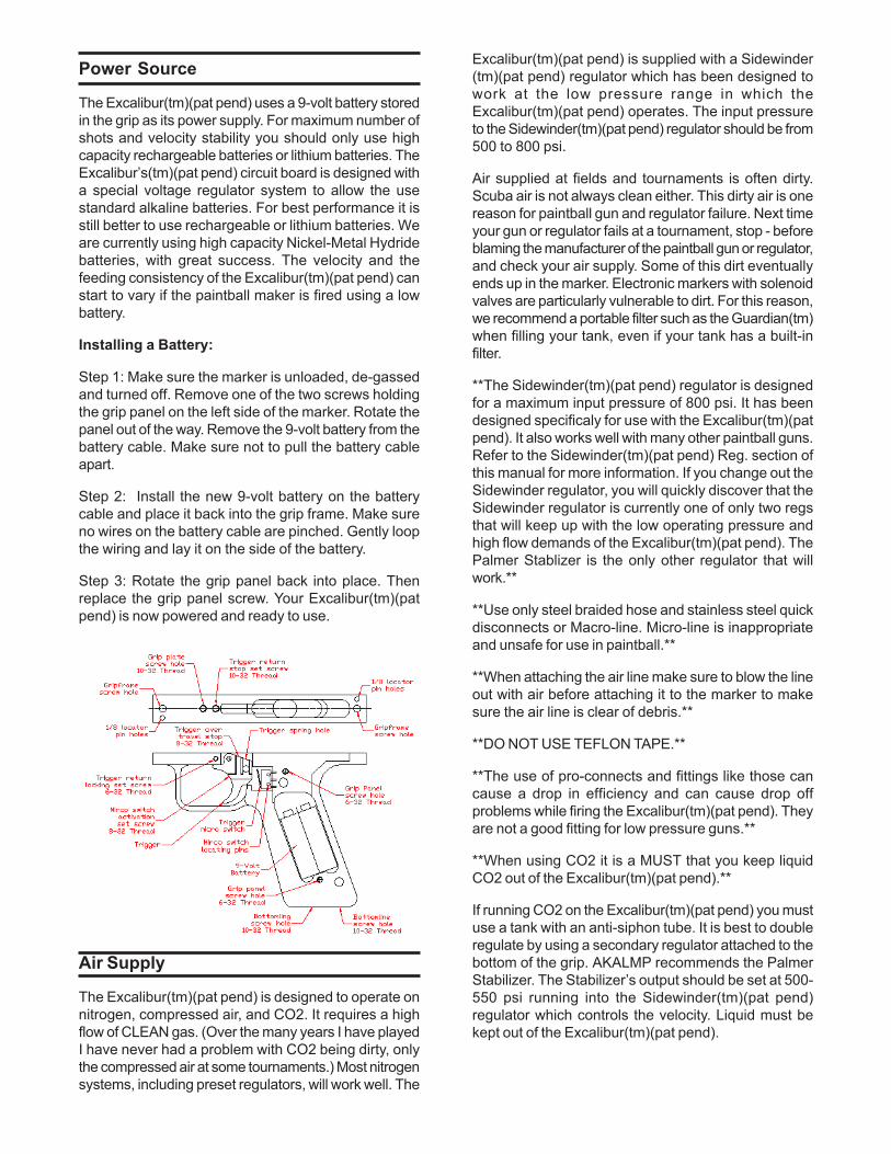
Power Source
The Excalibur(tm)(pat pend) uses a 9-volt battery storedin the grip as its power supply. For maximum number ofshots and velocity stability you should only use highcapacity rechargeable batteries or lithium batteries. TheExcalibur’s(tm)(pat pend) circuit board is designed witha special voltage regulator system to allow the usestandard alkaline batteries. For best performance it isstill better to use rechargeable or lithium batteries. Weare currently using high capacity Nickel-Metal Hydridebatteries, with great success. The velocity and thefeeding consistency of the Excalibur(tm)(pat pend) canstart to vary if the paintball maker is fired using a lowbattery.
Installing a Battery:
Step 1: Make sure the marker is unloaded, de-gassedand turned off. Remove one of the two screws holdingthe grip panel on the left side of the marker. Rotate thepanel out of the way. Remove the 9-volt battery from thebattery cable. Make sure not to pull the battery cableapart.
Step 2: Install the new 9-volt battery on the batterycable and place it back into the grip frame. Make sureno wires on the battery cable are pinched. Gently loopthe wiring and lay it on the side of the battery.
Step 3: Rotate the grip panel back into place. Thenreplace the grip panel screw. Your Excalibur(tm)(patpend) is now powered and ready to use.
Air Supply
The Excalibur(tm)(pat pend) is designed to operate onnitrogen, compressed air, and CO2. It requires a highflow of CLEAN gas. (Over the many years I have playedI have never had a problem with CO2 being dirty, onlythe compressed air at some tournaments.) Most nitrogensystems, including preset regulators, will work well. The
Excalibur(tm)(pat pend) is supplied with a Sidewinder(tm)(pat pend) regulator which has been designed towork at the low pressure range in which theExcalibur(tm)(pat pend) operates. The input pressureto the Sidewinder(tm)(pat pend) regulator should be from500 to 800 psi.
Air supplied at fields and tournaments is often dirty.Scuba air is not always clean either. This dirty air is onereason for paintball gun and regulator failure. Next timeyour gun or regulator fails at a tournament, stop - beforeblaming the manufacturer of the paintball gun or regulator,and check your air supply. Some of this dirt eventuallyends up in the marker. Electronic markers with solenoidvalves are particularly vulnerable to dirt. For this reason,we recommend a portable filter such as the Guardian(tm)when filling your tank, even if your tank has a built-infilter.
**The Sidewinder(tm)(pat pend) regulator is designedfor a maximum input pressure of 800 psi. It has beendesigned specificaly for use with the Excalibur(tm)(patpend). It also works well with many other paintball guns.Refer to the Sidewinder(tm)(pat pend) Reg. section ofthis manual for more information. If you change out theSidewinder regulator, you will quickly discover that theSidewinder regulator is currently one of only two regsthat will keep up with the low operating pressure andhigh flow demands of the Excalibur(tm)(pat pend). ThePalmer Stablizer is the only other regulator that willwork.**
**Use only steel braided hose and stainless steel quickdisconnects or Macro-line. Micro-line is inappropriateand unsafe for use in paintball.**
**When attaching the air line make sure to blow the lineout with air before attaching it to the marker to makesure the air line is clear of debris.**
**DO NOT USE TEFLON TAPE.**
**The use of pro-connects and fittings like those cancause a drop in efficiency and can cause drop offproblems while firing the Excalibur(tm)(pat pend). Theyare not a good fitting for low pressure guns.**
**When using CO2 it is a MUST that you keep liquidCO2 out of the Excalibur(tm)(pat pend).**
If running CO2 on the Excalibur(tm)(pat pend) you mustuse a tank with an anti-siphon tube. It is best to doubleregulate by using a secondary regulator attached to thebottom of the grip. AKALMP recommends the PalmerStabilizer. The Stabilizer’s output should be set at 500-550 psi running into the Sidewinder(tm)(pat pend)regulator which controls the velocity. Liquid must bekept out of the Excalibur(tm)(pat pend).
Excalibur Notes
AKALMP is continuosly refining the Excalibur to pushits performance to the extreme. Here is a list of thingsthat have changed between the different batchs ofmarkers. This manual covers most things on theExcalibur but be careful becuase there may be a changethat is not in this version of the manual yet. AKALMPreserves the right to revise and improve its products asit sees fit.
Serial numbers: 0 thru 57.
These are original production units. They have had thecircuit board and ram upgraded to the current version.These Excaliburs also used the Spyder style ball detentand non-threaded feed tubes.
Serial numbers: 58 thru 159.
Are equiped with the new circuit board and ram. Theyhave the new threaded feed tubes and other smalladjustments to set screw sizes to make assembleeasier. This version Excalibur uses the F-4 wire nubbin.
Serial numbers: 160 to present.
The barrel was moved back farther into the body byabout .125 to allow the paintball to be seated in thebarrel better. Set screw sizes were finalized. A few smalladjustments were made to the sizes of the air passagesto make the pneumatics more efficient. The bodies arenow completely finalized. The only thing left for the bodyis the ball drop sensor which is being worked on. Anytuning will now be in the cartridges themselves.
Febuary 21, 2001
A change in the Excaliburs valve spring was made. Wehave changed it from a spyder style valve spring to a 98cocker length spring. We have found this to helpeffeciency and also lower the sound signature of themarker more.
Notes:
As adjustments were made during production a few setscrew size changes, so be careful if you have to replaceone. Make sure it is the same size as the one removed.
The tube section of the valve chamber endcap is finethe way it is, some may want to cut the sides out of thetube section. We’ve tested that all ready and there wasno change in performance. Theres no need to cut thesides out.
There is no need to cut grooves on the outside of theram and hammer cartridge. The air flow around thecartridge is already high enough, if you cut groovesaround the outside you will only be slowing them down.
When the Excalibur is new the pneumatics reg needs
to be set at 90 to 100 psi. Once the Excalibur has hada few cases of paint through it you can adjust thepneumatics reg down around 70 to 80 psi.
Firing the Excalibur
Turning the Excalibur “ON” and airing it up:
Step 1: After making sure the marker is unloaded andde-gassed, push the bolt fully forward.
Step 2: Turn the marker “ON” using the recesed powerswitch. The raised screw on the back of the grip platenext to the power switch indicates the “ON” position forthe switch. There is no LED light to indicate the markeris on.
Step 3: Turn on the air source. If the bolt is not in itsforward postion it will now move forward closing thebreech. If air comes out of the barrel gently hold the boltback - this will allow the valve to seal.
Step 4: The paintball marker is now ready to use.
Step 5: Firmly grasp the grip, simply point and pull thetrigger
**Always keep your finger out of the trigger wellwhen you are not firing the paintball marker.**
Velocity Adjustment
The velocity of the Excalibur(tm)(pat pend) is controlleddirectly through the Sidewinder(tm)(pat pend) regulatormounted vertically in front of the trigger frame.
The Sidewinder(tm)(pat pend) regulator that comes withthe Excalibur(tm)(pat pend) is adjusted in this fashion:
1. Turning the adjuster screw clockwise will lower thepressure, thus lowering the velocity.
2. Turning the adjuster screw counter-clockwisewill increase the pressure raising the velocity.
When making velocity adjustments you should useextremely fine adjustments so as not to go past thedesired velocity. If you are unsure where your operatingpressure is, simply turn the pressure down until thevelocity drops to about 200 fps then slowly turn thepressure back up.
**Do not exceed avelocity of 300 FPS**
Cleaning and Maintenance
The barrel on the Excalibur(tm)(pat pend) can be cleanedduring a game by either unscrewing the barrel from themarker or by removing the bolt and swabbing throughthe marker and the barrel.
The bolt can be field-stripped from the Excalibur(tm)(patpend) while the marker is pressurized with gas. Thisallows you to clean the marker and oil the bolt whenneeded.
The Excalibur(tm)(pat pend) should be cleanedexternally using a cotton cloth and window cleaner or a50% alcohol/water mixture.
All external and internal moving parts should be lubricatedusing a light synthetic oil only. Oil can be added byplacing a few drops in the input quick disconnect on theSidewinder(tm)(pat pend) regulator and then dry firingthe gun. A few drops should also be placed on the o-rings on the Lightning bolt. This should be done everytime you play, and the bolt should be oiledthroughout the day of play.
Recommended lubricants: Extreme-lube from AKALMPor Palmer Pursuits paintball gun oil.
**Under no circumstances should you use Vaseline,WD-40, Grease of any kind, Engine Oil, 3-in-1, gunoils, and any similar oils. If you have a questionabout the type of paintball gun oil you are using e-mail us.**
The electronics are protected against moisture, but theExcalibur’s(tm)(pat pend) electronic compontents shouldnever be immersed in water or damage may occur.
All the threads on the Excalibur(tm)(pat pend) areAmerican threads. All set screws are American sizes.
Excalibur(tm)(pat pend) maintenance schedule:
Though the Excalibur(tm)(pat pend) was designed to bevirtually maintenance free the Excalibur(tm)(pat pend)will give you many years of use if normal maintenanceis done to the marker. Even if the Excalibur(tm)(patpend) does not need it, good maintenance will keep itrunning properly for many years. Every time you play,put a few drops of oil into the input quick disconnect onthe Sidewinder (tm)(pat pend) regulator.
Once a month, remove the cartridges and clean themarker.
Every 25,000 cycles or 3 months:
Check the output pressure of the Pneumatics Reg.
Every 50,000 cycles or 6 months:
Inspect, and replace if needed, the Ram and hammer o-rings.
Inspect the regulator seat on the pneumatics regulatorand the Sidewinder(tm)(pat pend) regulator for wear.
Inspect the Urethane bumper on the Ram and Hammerfor wear.
Every 75,000 cycles or 9 months:
Inspect, and replace if needed, the Ram and hammer o-rings.
Inspect the regulator seat on the pneumatics regulatorand the Sidewinder(tm)(pat pend) regulator for wear.
Inspect the Urethane bumper on the Ram and Hammerfor wear.
Every 100,000 cycles or once a year:
Inspect the whole marker for any signs of problems thatcould be starting.
If the Excalibur(tm)(pat pend) is to be stored for morethen two months, remove the valve spring. This willincrease the spring’s lifespan. It is a good idea to dothis with both hammer and valve springs on any paintballgun that is to be stored for a long time.
Troubleshooting
Excalibur(tm)(pat pend) will not fire
Is there a battery in the Excalibur(tm)(pat pend)?- See Power Supply.
Is there air/nitrogen or CO2 gas present?- See Air Supply.
Was the compressed air or nitrogen clean?
Is the Excalibur(tm)(pat pend) turned on?- See Power Supply.
Is the trigger adjusted correctly?- See Trigger Adjustment.
Is the bolt jammed?
Is the pneumatics regulator working?- See Pneumatics Reg.
Is the circuit board working?- See Electronics.
Is the hammer dwell set correctly?- See Electronics. Check for damaged wiring.
Velocity too Low or too High
Is output pressure from Sidewinder regulator setcorrectly?- See Sidewinder Reg.
Is hammer dwell adjustment set correctly?- See Electronics.
Is hammer piston o-ring in good shape?- See Hammer.
Is the pneumatics regulator set correctly?- See Pneumatics Reg.
Is the battery fresh and new?- See Power Supply.
Chopping paintballs
Is your hopper working correctly?
Is your bolt “OPEN” dwell set correctly- See Electronics.
Is your ball detent working?- See Ball Detent.
Is the pneumatics regulator set correctly?- See Pneumatics Reg.
Is the battery fresh and new?- See Power Supply.
Firing too slow
Is your rate of fire (ROF) set correctly?- See Electronics.
Are the dwell settings correct?- See Electronics.
Is the pneumatics regulator set correctly?- See Pneumatics Reg.
Is the battery fresh and new?- See Power Supply.
Excessive gas consumption
Is hammer dwell set correctly?- See Electronics.
Is there a leak?
Gas leaking
Leaking from Tornado(tm)(pat # 5791328) valve?- See Tornado Valve.
Leaking from Ram (pneumatic cylinder)? - See Ram.
Leaking from Pneumatics Regulator?- See Pneumatics Reg.
Leaking from Sidewinder(tm)(pat pend) Regulator?- See Sidewinder Reg.
Leaking from Solenoid valves?
Electronic problems
Check battery power level.- See Power Supply.
Check for damaged wiring.
Check circuit board dwell settings.- See Electronics.
Custom Work
For the customers that want splash, custom coloranodizing and have custom mill work, there are versionsof the Excalibur(tm)(pat pend) available through ourauthorized airsmiths that can be made into custommarkers. These markers are still covered under factorywarranty if the work is done by an authorized airsmith.AKALMP will be doing a limited number of customExcaliburs. A complete list of our authorized airsmithscan be found on our web site, akalmp.com.
If you wish to do the work yourself, or have non-factoryauthorized airsmith do the work, please be careful. Thefactory warranty will be void. When doing custom colors,do not strip the hard anodized bodies, bare aluminumbodies are available from AKALMP. The hammer tube,hammer endcap, pneumatics regulator tube, ram tubeand ram endcap should not be stripped of their hardanodizing. Doing so can cause wear. Striping theanodizing from these pieces will void the factory warrantyon these pieces.
When doing custom mill work to the body of theExcalibur be aware there are a few area that you shouldstay away from and a few areas that have critical depths.In the schematics section of this manual there aredrawings that specify the areas to be careful of whendoing custom mill work.
If you have a custom shop build a custom milled andanodized Excalibur(tm)(pat pend) the gun body and feedtube should be anodized seperately. Then use blue Loc-tite when you screw the feedtube and body together.
On the rear of the Excalibur(tm)(pat pend) there are twoset screws, the lower of which is the hanging screwhole for anodizing. Because anodizing requires anelectrical charge, the second set screw hole is providedfor a threaded electrode. The upper set screw is theplug hole for the air passage.
Accessories
Warp Feed adapter:
This adapter replaces the standard threaded feed tubewith a new feed tube that will allow you to attach thefeed adapter for the warp feed system.
Part number: (available soon)
Programmer cable:
The adaptor that hooks to the Excalibur(tm)(pat pend)and to your PC or laptop so you can adjust the timingsettings.
Part number: (available soon)
Tool Kit:
The tool kit contains the necessary specialty tools forproperly disassembling the Excalibur(tm)(pat pend).
Part Description: Part Number:
Pneumatics reg removal wrench
Hammer spanner wrench
Pneumatics reg tester
Pressure gauge
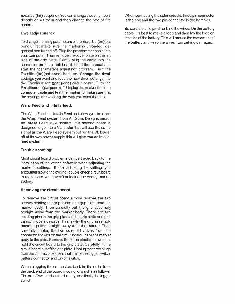
Ball Detent
The Excalibur(tm)(pat pend) has been supplied with aball detent to keep paintballs from double feeding. Sincethe Excalibur(tm)(pat pend) is an electronically controlledsystem, it does not require a ball detent but we thoughtit would be a nice back up.
Replacement of ball detent:
The ball detent may become worn or broken over time.This is normal. The standard Excalibur(tm)(pat pend)uses an F4 wire nubbin. They are available through yourlocal airsmiths. Some custom Excaliburs(tm)(pat pend)may have a different ball detent.
To replace the detent.
1. Remove the two 4-40 button head screws.
2. Lift the cover plate away from the body of theExcalibur(tm)(pat pend).
3. Remove the detent and replace with a new one.
4. Re-install the cover plate and the two screws. Do notover tighten, just snug them down.
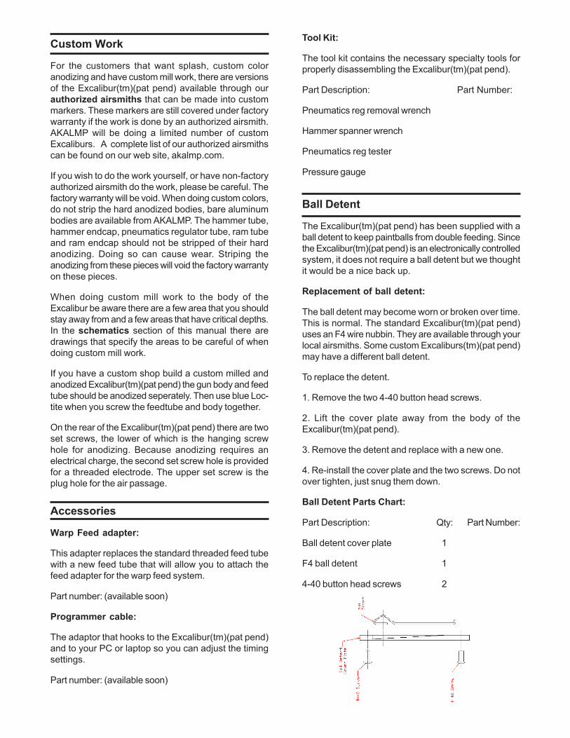
Ball Detent Parts Chart:
Part Description: Qty: Part Number:
Ball detent cover plate 1
F4 ball detent 1
4-40 button head screws 2
Electronics
The Excalibur(tm)(pat pend) is controlled by a state ofthe art software driven computer board. The newer designruns the Excalibur(tm)(pat pend) at its true fire ratecapability unlike the original circuit board in the first 40Excaliburs(tm)(pat pend). The board is equipped withmany features that are not found on other electronicpaintball markers. First the board is equipped with aspecial voltage regulator system that will increase thelife span of the battery. The board is made withconnectors for every attachment necessary. No solderingof wires is needed. If the trigger micro switch goes badjust unplug it and replace with a new one. The samegoes for the battery plug, the on-off switch, and thesolenoid valves. There is also a programming port and arecharging port. When using rechargeable batteries youdon’t have to remove the battery just use an adaptorand recharge the battery. There is also a port that willsupport a ball breech sensor, Warp Feed and an Intellafeed system. The circuit board is protected againstmoisture,but do not immerse the Excalibur(tm)(pat pend)in water. The Excalibur(tm)(pat pend) is tournament legal,as the board operates in semi-automatic mode only.
***Warning any tampering with the circuit boardwill cause it to erase the program from thecomputer chip. The board would then have to bereprogramed at the factory.***
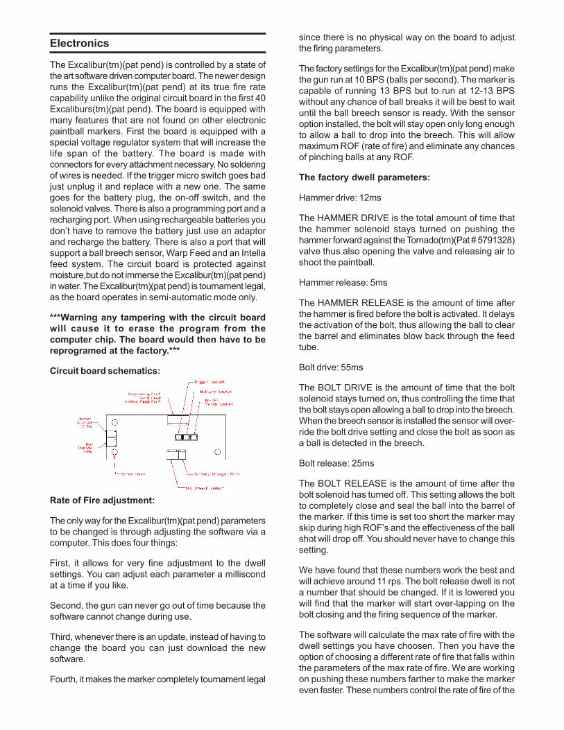
Circuit board schematics:
Rate of Fire adjustment:
The only way for the Excalibur(tm)(pat pend) parametersto be changed is through adjusting the software via acomputer. This does four things:
First, it allows for very fine adjustment to the dwellsettings. You can adjust each parameter a milliscondat a time if you like.
Second, the gun can never go out of time because thesoftware cannot change during use.
Third, whenever there is an update, instead of having tochange the board you can just download the newsoftware.
Fourth, it makes the marker completely tournament legal
since there is no physical way on the board to adjustthe firing parameters.
The factory settings for the Excalibur(tm)(pat pend) makethe gun run at 10 BPS (balls per second). The marker iscapable of running 13 BPS but to run at 12-13 BPSwithout any chance of ball breaks it will be best to waituntil the ball breech sensor is ready. With the sensoroption installed, the bolt will stay open only long enoughto allow a ball to drop into the breech. This will allowmaximum ROF (rate of fire) and eliminate any chancesof pinching balls at any ROF.
The factory dwell parameters:
Hammer drive: 12ms
The HAMMER DRIVE is the total amount of time thatthe hammer solenoid stays turned on pushing thehammer forward against the Tornado(tm)(Pat # 5791328)valve thus also opening the valve and releasing air toshoot the paintball.
Hammer release: 5ms
The HAMMER RELEASE is the amount of time afterthe hammer is fired before the bolt is activated. It delaysthe activation of the bolt, thus allowing the ball to clearthe barrel and eliminates blow back through the feedtube.
Bolt drive: 55ms
The BOLT DRIVE is the amount of time that the boltsolenoid stays turned on, thus controlling the time thatthe bolt stays open allowing a ball to drop into the breech.When the breech sensor is installed the sensor will over-ride the bolt drive setting and close the bolt as soon asa ball is detected in the breech.
Bolt release: 25ms
The BOLT RELEASE is the amount of time after thebolt solenoid has turned off. This setting allows the boltto completely close and seal the ball into the barrel ofthe marker. If this time is set too short the marker mayskip during high ROF’s and the effectiveness of the ballshot will drop off. You should never have to change thissetting.
We have found that these numbers work the best andwill achieve around 11 rps. The bolt release dwell is nota number that should be changed. If it is lowered youwill find that the marker will start over-lapping on thebolt closing and the firing sequence of the marker.
The software will calculate the max rate of fire with thedwell settings you have choosen. Then you have theoption of choosing a different rate of fire that falls withinthe parameters of the max rate of fire. We are workingon pushing these numbers farther to make the markereven faster. These numbers control the rate of fire of the
Excalibur(tm)(pat pend). You can change these numbersdirectly or set them and then change the rate of firecontrol.
Dwell adjustments:
To change the firing parameters of the Excalibur(tm)(patpend), first make sure the marker is unloaded, de-gassed and turned off. Plug the programmer cable intoyour computer. Then remove the cover plate on the leftside of the grip plate. Gently plug the cable into theconnector on the circuit board. Load the manual andstart the “parameters adjusting” program. Turn theExcalibur(tm)(pat pend) back on. Change the dwellsettings you want and load the new dwell settings intothe Excalibur’s(tm)(pat pend) circuit board. Turn theExcalibur(tm)(pat pend) off. Unplug the marker from thecomputer cable and test the marker to make sure thatthe settings are working the way you want them to.
Warp Feed and Intella feed:
The Warp Feed and Intella Feed port allows you to attachthe Warp Feed system from Air Guns Deisgns and/oran Intella Feed style system. If a second board isdesigned to go into a VL loader that will use the samesignal as the Warp Feed system but run the VL loaderoff of its own power supply this will give you an Intella-feed system.
Trouble shooting:
Most circuit board problems can be traced back to theinstallation of the wrong software when adjusting themarker’s settings. If after adjusting the settings youencounter slow or no cycling, double check circuit boardto make sure you haven’t selected the wrong markersetting.
Removing the circuit board:
To remove the circuit board simply remove the twoscrews holding the grip frame and grip plate onto themarker body. Then carefully pull the grip assemblystraight away from the marker body. There are twolocating pins in the grip plate so the grip plate and gripcannot move sideways. This is why the grip assemblymust be pulled straight away from the marker. Thencarefully unplug the two solenoid valves from theconnector sockets on the circuit board. Place the markerbody to the side. Remove the three plastic screws thathold the circuit board to the grip plate. Carefully lift thecircuit board out of the grip plate. Unplug the three plugsfrom the connector sockets that are for the trigger switch,battery connector and on-off switch.
When plugging the connectors back in, the order fromthe back end of the board moving forward is as follows.The on-off switch, then the battery, and finally the triggerswitch.
When connecting the solenoids the three pin connectoris the bolt and the two pin connector is the hammer.
Be careful not to pinch or bind the wires. On the batterycable it is best to make a loop and then lay the loop onthe side of the battery. This will reduce the movement ofthe battery and keep the wires from getting damaged.
Hammer
Mechanical Hammer adjustment:
There is no mechanical adjustment to the hammer itself.Simply screw the hammer cartridge in until it stopsagainst the body.
Hammer maintenace:
The o-ring on the hammer piston is sized to maintain aconstant fricton to the inside of the bore of the hammercartridge. Keeping a constant fricton on the bore isimportant to keep a consistent velocity. If the o-ringwears out, the fricton will change and in turn change theconsistency of force with which the hammer strikes thevalve. So, it is important to keep that o-ring in goodorder and properly oiled.
To pull the hammer cartridge out of the marker: Use a 5/32 allen wrench and unscrew the hammer cartridge.Then gently pull it out the back of the Excalibur(tm)(patpend).
Use the hammer spanner wrench and an allen wrenchto loosen the hammer endcap. Unscrew the endcapfrom the hammer cartridge and gently pull pieces apart.You can now replace the majority of o-rings and u-cups.Re-assemble in reverse order.
Carefully re-install everything and tighten down thehammer endcap. Be careful not to over-tighten. Makesure the -013 o-ring on the endcap is in good condition.It will keep the nose from coming loose. You will alsowant to put a small drop of BLUE Loctite on the threadsas you re-assemble the hammer cartridge.
Trouble shooting:
Air leaking from solenoid:
1. Check the solenoid valve, it may need to be replaced.
2. Check the hammer piston o-ring. Air may be leakingaround it. If air is leaking around it, replace the hammerpiston o-ring.
Air leaking around the front of the hammer:
1. Check the u-cup. It may need to be replaced.
2. Check the o-rings on the outside of the cartridge.
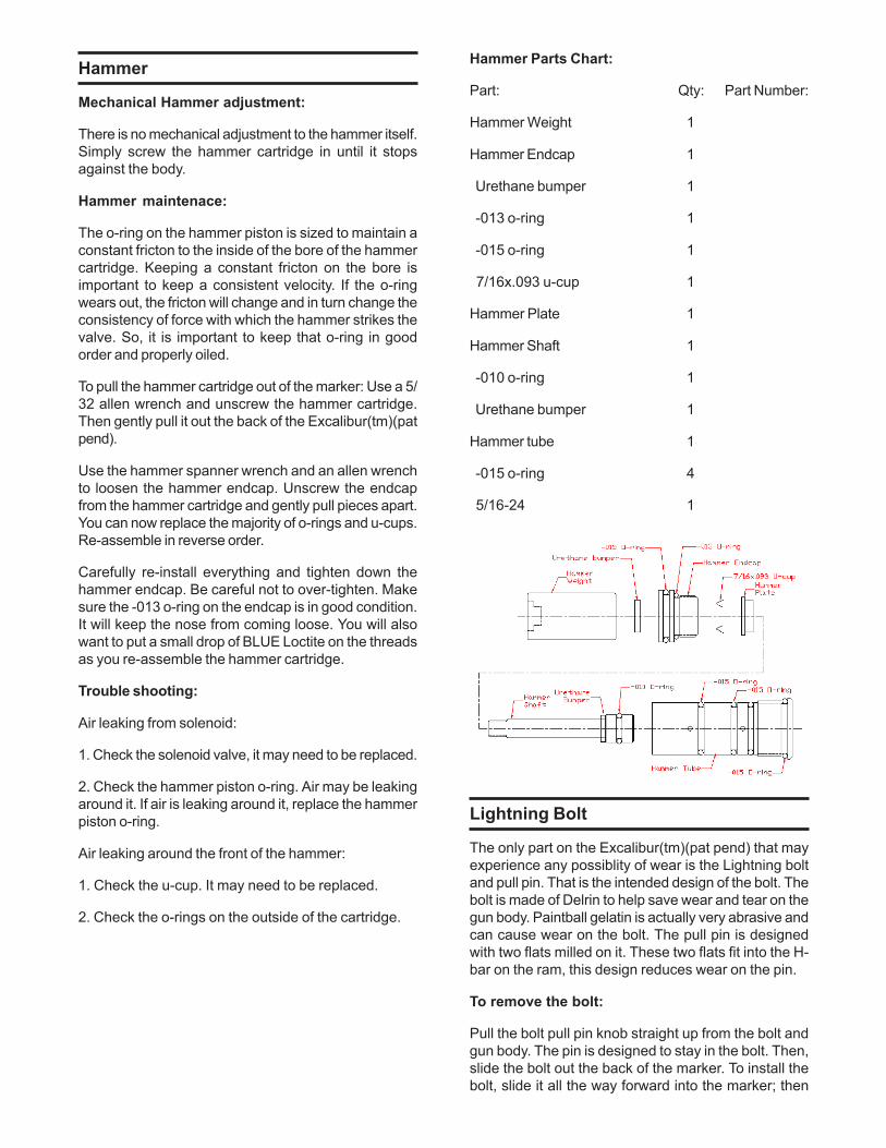
Hammer Parts Chart:
Part: Qty: Part Number:
Hammer Weight 1
Hammer Endcap 1
Urethane bumper 1
-013 o-ring 1
-015 o-ring 1
7/16x.093 u-cup 1
Hammer Plate 1
Hammer Shaft 1
-010 o-ring 1
Urethane bumper 1
Hammer tube 1
-015 o-ring 4
5/16-24 1
Lightning Bolt
The only part on the Excalibur(tm)(pat pend) that mayexperience any possiblity of wear is the Lightning boltand pull pin. That is the intended design of the bolt. Thebolt is made of Delrin to help save wear and tear on thegun body. Paintball gelatin is actually very abrasive andcan cause wear on the bolt. The pull pin is designedwith two flats milled on it. These two flats fit into the H-bar on the ram, this design reduces wear on the pin.
To remove the bolt:
Pull the bolt pull pin knob straight up from the bolt andgun body. The pin is designed to stay in the bolt. Then,slide the bolt out the back of the marker. To install thebolt, slide it all the way forward into the marker; then
push the bolt pull pin down until it latches into the H-bar.
The screw in the back of the bolt adjusts the tensionand locking of the bolt pull pin. You should not have toadjust this. But, if you do, adjust the ball plunger in untilyou cannot pull the bolt pull pin up. Then slowly back itoff until the pin moves at the desired tension. Do notadjust the tension too far out or the pin can come loose.
Trouble shooting:
Pull Pin stuck:
1. Check the ball plunger in the back of the bolt, it maybe stuck.
Bolt not sliding smoothly:
1. Check the o-rings on the bolt to make sure they arenot swollen. Replace them or properly oil them.
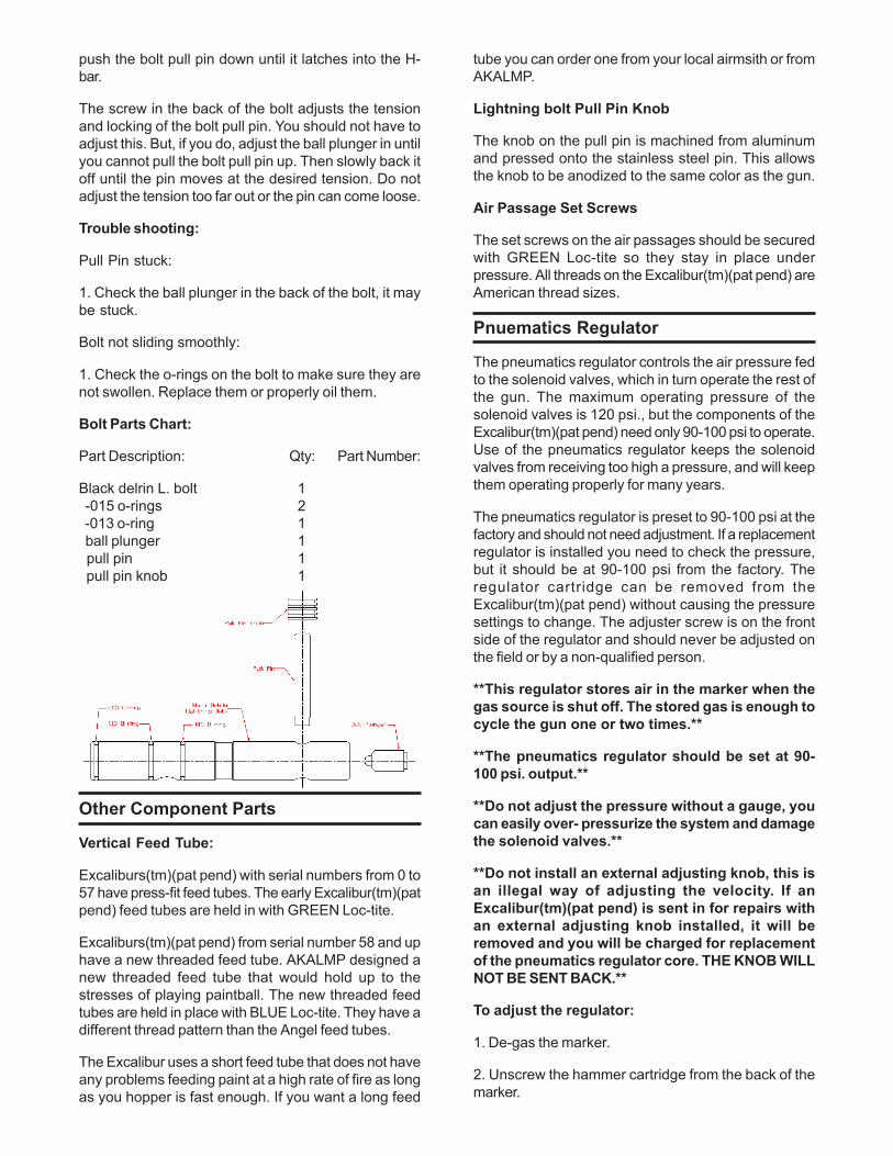
Bolt Parts Chart:
Part Description: Qty: Part Number:
Black delrin L. bolt 1 -015 o-rings 2 -013 o-ring 1 ball plunger 1 pull pin 1 pull pin knob 1
Other Component Parts
Vertical Feed Tube:
Excaliburs(tm)(pat pend) with serial numbers from 0 to57 have press-fit feed tubes. The early Excalibur(tm)(patpend) feed tubes are held in with GREEN Loc-tite.
Excaliburs(tm)(pat pend) from serial number 58 and uphave a new threaded feed tube. AKALMP designed anew threaded feed tube that would hold up to thestresses of playing paintball. The new threaded feedtubes are held in place with BLUE Loc-tite. They have adifferent thread pattern than the Angel feed tubes.
The Excalibur uses a short feed tube that does not haveany problems feeding paint at a high rate of fire as longas you hopper is fast enough. If you want a long feed
tube you can order one from your local airmsith or fromAKALMP.
Lightning bolt Pull Pin Knob
The knob on the pull pin is machined from aluminumand pressed onto the stainless steel pin. This allowsthe knob to be anodized to the same color as the gun.
Air Passage Set Screws
The set screws on the air passages should be securedwith GREEN Loc-tite so they stay in place underpressure. All threads on the Excalibur(tm)(pat pend) areAmerican thread sizes.
Pnuematics Regulator
The pneumatics regulator controls the air pressure fedto the solenoid valves, which in turn operate the rest ofthe gun. The maximum operating pressure of thesolenoid valves is 120 psi., but the components of theExcalibur(tm)(pat pend) need only 90-100 psi to operate.Use of the pneumatics regulator keeps the solenoidvalves from receiving too high a pressure, and will keepthem operating properly for many years.
The pneumatics regulator is preset to 90-100 psi at thefactory and should not need adjustment. If a replacementregulator is installed you need to check the pressure,but it should be at 90-100 psi from the factory. Theregulator cartridge can be removed from theExcalibur(tm)(pat pend) without causing the pressuresettings to change. The adjuster screw is on the frontside of the regulator and should never be adjusted onthe field or by a non-qualified person.
**This regulator stores air in the marker when thegas source is shut off. The stored gas is enough tocycle the gun one or two times.**
**The pneumatics regulator should be set at 90-100 psi. output.**
**Do not adjust the pressure without a gauge, youcan easily over- pressurize the system and damagethe solenoid valves.**
**Do not install an external adjusting knob, this isan illegal way of adjusting the velocity. If anExcalibur(tm)(pat pend) is sent in for repairs withan external adjusting knob installed, it will beremoved and you will be charged for replacementof the pneumatics regulator core. THE KNOB WILLNOT BE SENT BACK.**
To adjust the regulator:
1. De-gas the marker.
2. Unscrew the hammer cartridge from the back of themarker.
3. Install the pneumatics regulator test chamber intothe hammer tube. Then install the low pressure gaugeon the test chamber.
4. Gas up the gun to 200 psi from the Sidewinder(tm)(patpend) regulator and check the pressure. Using an allenwrench, adjust the regulator core clockwise to lowerthe pressure and counter clockwise to raise thepressure. You will have to cycle the marker while youadjust the regulator to get the pressure to change. Theadjustment is very sensitive.
5. Once the correct pressure is achieved, turn the air onand off and cycle the marker several times to makesure the pneumatics regulator stays at the new setting.
Disassembly of the Pneumatics Reg:
1. Using the pneumatics reg. removal tool, unscrew thepneumatic reg from the front of the Excalibur(tm)(patpend).
2. Gently clamp the Pn-reg body between the two piecesof wood.
3. Use the pneumatic reg removal tool and a wrenchand break the BLUE Loc-tite seal between the two halves.
4. Unscrew the pn-reg endcap. Remove the reg-washerand o-ring from the end of the pn-reg body. You can alsounscrew the reg core from the pn-reg endcap throughthe back of it, but not through the front.
5. Using snap ring pliers remove the snap ring from theend of the pn-reg body.
6. Gently push the reg psiton and spring out of the pn-reg body using something soft like a plastic ball pointpen which will not damage the sealing area of theregulator piston.
7. You can now replace all o-rings and springs, if needed,and reassemble in reverse.
**There are two sides to snap rings and it isimportant which side faces out of the pn-reg body.One side has squared off, sharp edges and oneside has edges that are rolled over. When installingthe snap ring make sure the sharp square edgefaces to the outside of the pn-reg body.**
Trouble shooting:
Air leaking from the front of the regulator:
1. Check the o-rings around the reg-core.
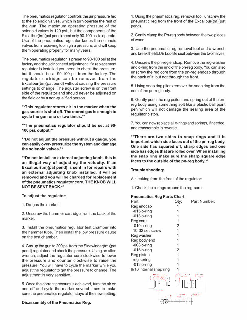
Pneumatics Reg Parts Chart:Part: Qty: Part Number:Reg endcap 1 -015 o-ring 1 -013 o-ring 1Reg core 1 -010 o-ring 2 10-32 set screw 1Reg washer 1Reg body end 1 -008 o-ring 1 -015 o-ring 2Reg piston 1 reg spring 1 -013 o-ring 19/16 internal snap ring 1
Pneumatic Ram
Removal of Pneumatic Cyclinder (ie: the Ram):
De-gas the marker and remove all paint. Remove thebolt, the body endcap, and pneumatics regulator. Thenremove the set screw pin that holds the ram in place.Using a 1/2" dia wood dowel rod, gently push the ramout through the back of the marker body.
Disassembly.
Insert a 1/4" dia metal rod in the set screw pin hole. Youmay have to polish the 1/4" rod just a little to get it to fitproperly. Then, using an adjustable wrench, unscrewthe front nose from the ram tube by using the 1/4" diarod to turn the ram tube. Pull the two halves apart. Youcan now replace most of the O-rings and U-cups if needbe. To remove the H-Bar use the end of the pneumaticsreg tool that fits holes on the H-bar and clamp the backend of the ram between two pieces of wood or in a 3/8"collet. Reassemble in reverse and tighten down gently.You must use a small drop of BLUE Loctite on the threadsto keep everything tight. When you re-install the ram itis a must that you use BLUE loc-tite on the ram retainingpin threads to keep it from coming loose when the gunis in use. Do not over-tighten the pin.
**Be careful not to damage the ram piston o-ringwhen you re-install the ram shaft into the ramtube.**
Trouble shooting:
Air leaking from solenoid:
1. Check the solenoid valve, it may need to be replaced.
2. Check the ram piston o-ring. Air may be leakingaround it. If air is leaking around it, replace the rampiston o-ring.
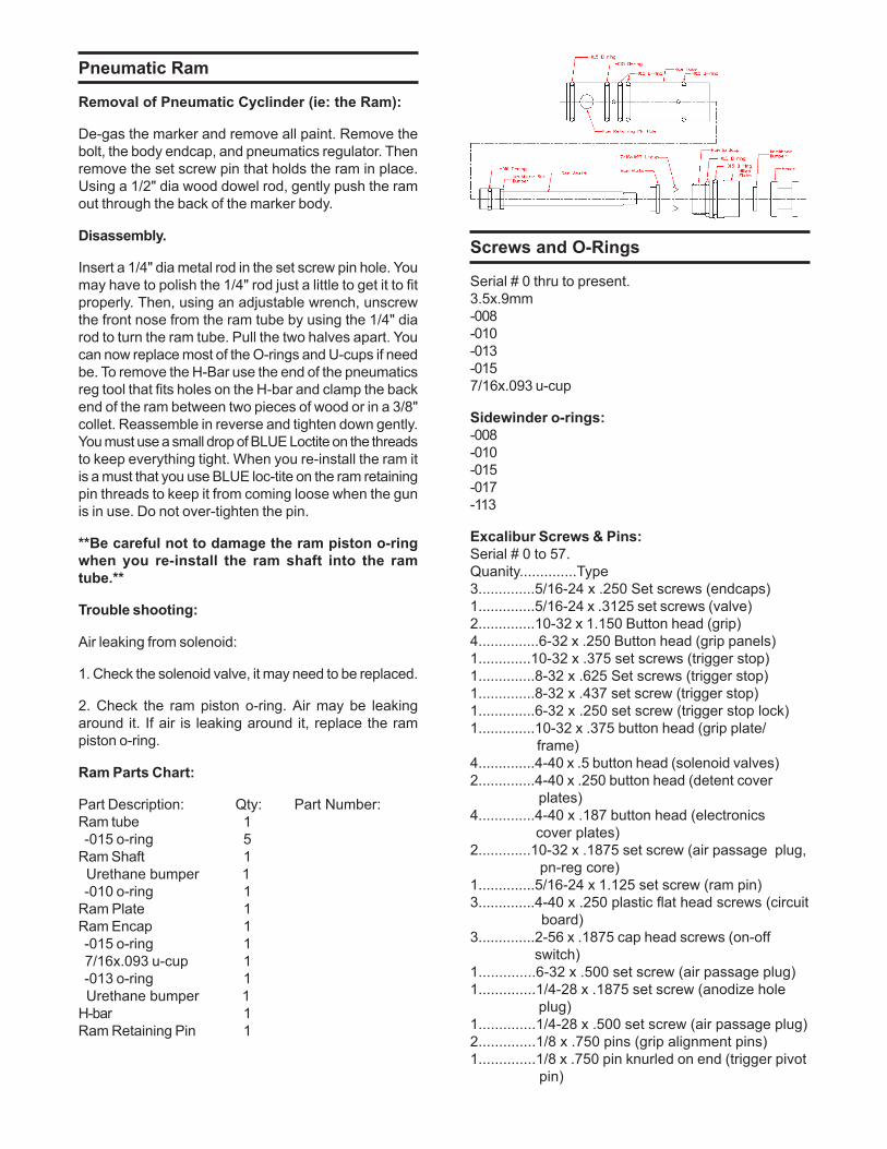
Ram Parts Chart:
Part Description: Qty: Part Number:Ram tube 1 -015 o-ring 5Ram Shaft 1 Urethane bumper 1 -010 o-ring 1Ram Plate 1Ram Encap 1 -015 o-ring 1 7/16x.093 u-cup 1 -013 o-ring 1 Urethane bumper 1H-bar 1Ram Retaining Pin 1
Screws and O-Rings
Serial # 0 thru to present.3.5x.9mm-008-010-013-0157/16x.093 u-cup
Sidewinder o-rings:-008-010-015-017-113
Excalibur Screws & Pins:Serial # 0 to 57.Quanity..............Type3..............5/16-24 x .250 Set screws (endcaps)1..............5/16-24 x .3125 set screws (valve)2..............10-32 x 1.150 Button head (grip)4...............6-32 x .250 Button head (grip panels)1.............10-32 x .375 set screws (trigger stop)1..............8-32 x .625 Set screws (trigger stop)1..............8-32 x .437 set screw (trigger stop)1..............6-32 x .250 set screw (trigger stop lock)1..............10-32 x .375 button head (grip plate/ frame)4..............4-40 x .5 button head (solenoid valves)2..............4-40 x .250 button head (detent cover plates)4..............4-40 x .187 button head (electronics cover plates)2.............10-32 x .1875 set screw (air passage plug, pn-reg core)1..............5/16-24 x 1.125 set screw (ram pin)3..............4-40 x .250 plastic flat head screws (circuit board)3..............2-56 x .1875 cap head screws (on-off switch)1..............6-32 x .500 set screw (air passage plug)1..............1/4-28 x .1875 set screw (anodize hole plug)1..............1/4-28 x .500 set screw (air passage plug)2..............1/8 x .750 pins (grip alignment pins)1..............1/8 x .750 pin knurled on end (trigger pivot pin)
2..............6-32 x .125 set screw (air passage plug)1..............6-32 x .500 set screw (air passage plug)1..............1/4-28 x .1875 set screw (anodize hole plug)1..............1/4-28 x .500 set screw (air passage plug)2..............1/8 x .750 pins (grip alignment pins)1..............1/8 x .750 pin knurled on end (trigger pivot pin)2..............2x18mm pins (micro-switch pins)
Serial # 58 to 159.Quanity..............Type2..............5/16-24 x .250 Set screws (endcaps)2..............5/16-24 x .3125 set screws (endcaps and valve)2..............10-32 x 1.000 Button head (grip)4..............6-32 x .250 Button head (grip panels)1..............10-32 x .375 set screws (trigger stop)1..............8-32 x .625 Set screws (trigger stop)1..............8-32 x .437 set screw (trigger stop)1..............6-32 x .250 set screw (trigger stop lock)1..............10-32 x .375 button head (grip plate/frame)4..............4-40 x .5 button head (solenoid valves)2..............4-40 x .250 button head (detent cover plates)4..............4-40 x .187 button head (electronics cover plates)2..............10-32 x .1875 set screw (air passage plug, pn-reg core)1..............5/16-24 x 1.125 set screw (ram pin)3..............4-40 x .250 plastic flat head screws (circuit board)3..............2-56 x .1875 cap head screws (on-off switch)2..............8-32 x .125 set screw (air passage plug)1..............6-32 x .500 set screw (air passage plug)1..............1/4-28 x .1875 set screw (anodize hole plug)1..............1/4-28 x .500 set screw (air passage plug)2..............1/8 x .750 pins (grip alignment pins)1..............1/8 x .750 pin knurled on end (trigger pivot pin)2..............2x18mm pins (micro-switch pins)
Serial # 160 thru to present.Quanity..............Type4..............5/16-24 x .3125 set screws (endcaps & valve)2..............10-32 x 1.000 Button head (grip)4..............6-32 x .250 Button head (grip panels)1..............10-32 x .375 set screws (trigger stop)1..............8-32 x .625 Set screws (trigger stop)1..............8-32 x .437 set screw (trigger stop)1..............6-32 x .250 set screw (trigger stop lock)1..............10-32 x .375 button head (grip plate/frame)4..............4-40 x .5 button head (solenoid valves)2..............4-40 x .250 button head (detent cover plates)4..............4-40 x .187 button head (electronics cover plates)
2..............10-32 x .1875 set screw (air passage plug, pn-reg core)1..............5/16-24 x 1.125 set screw (ram pin)3..............4-40 x .250 plastic flat head screws (circuit board)3..............2-56 x .1875 cap head screws (on-off switch)2..............8-32 x .125 set screw (air passage plug)1..............8-32 x .500 set screw (air passage plug)1..............1/4-20 x .1875 set screw (anodize hole plug)1..............1/4-28 x .500 set screw (air passage plug)2..............1/8 x .750 pins (grip alignment pins)1..............1/8 x .750 pin knurled on end (trigger pivot pin)2..............2x18mm pins (micro-switch pins)
Sidewinder Regulator
The Sidewinder(tm)(Pat Pend) regulator was designedspecificaly for use on the Excalibur(tm)(pat pend)because of its extremely low operating pressure ofaproximately 140-150 psi. This regulator will work wellon other guns,also. The design of the regulator permitsthe air hose to be connected to the gun in any locationthe user wishes within a 360 degree circle around thebase of the reg, while still allowing the regulator to beexternally adjusted from the bottom. The top endcap ofthe regulator can be replaced with different length onesto allow the user to adjust total length of the reg.
**If you change out the Sidewinder(tm)(pat pend)regulator, you will quickly discover that it iscurrently one of only two regs that will keep upwith the low operating pressure and high flowdemands of the Excalibur(tm)(pat pend). Currentlythe Palmer Stablizer is the only other regulatorthat will work. **
Sidewinder(tm)(pat pend) Specifications:Model: Sidewinder(tm)(pat pend)Version:BGas Source: Compressed air, Nitrogen or CO2Length: 4.875 inchesWidth: 1.00 dia main body/1.125 dia swivel sleeveWeight: .308 lbs (With quick disconnect)Externally Adjustable Output Pressure: 0-700 PSIInput pressure: 400-800 PSI
Adjusting the Sidewinder(tm)(pat pend) Regulator:
Decrease output:
Looking at the regulator from the bottom, turn the allenwrench clockwise to decrease the pressure.
Increase output:
Looking at the regulator from the bottom, turn the allenwrench counter clockwise to increase the pressure.
Dead Zone:
Since the Sidewinder(tm)(pat pend) regulator wasdesigned to go down to zero psi output, there is spaceafter it reaches zero that the adjuster screw can beturned farther. If you turn the adjuster screw gently untilit bottoms out, then it will be 4 to 5 turns counterclockwise until the pressure starts to rise again. This isthe dead zone.
Side Notes and Trouble Shooting:
Remember to shoot the gun several times after anyadjustment to the Sidewinder(tm)(pat pend) regulatorso you can make sure the velocity stabilizes.
If the regulator creeps in pressure range, check to makesure there is not a piece of debris inbetween the regulatorseat and the regulator piston. If it continues to creepreplace the reg core.
When using the Sidewinder(tm)(pat pend) with CO2 youwill have to oil the regulator on a more regular basis.The CO2 carries the oil away from the moving partsquicker then nitrogen does.
Make sure the vent hole on the side of regulator bodymiddle is open and clean. If it is plugged the regulatorwill not fuction properly.
The Sidewinder(tm)(pat pend) regulator is only designedfor a maximum input pressure of 800 psi.
Use only steel braided hose and stainless steel quickdisconnects. Mirco-line and Macro-line is inappropriateand unsafe for use in paintball.
When using CO2 it is a must that you keep liquid CO2out of the Excalibur(tm)(pat pend).
Disassembly of Sidewinder(tm)(pat pend)Regulator:
To properly disassemble the Sidewinder(tm)(pat pend)regulator and not scratch the outside, you will need afew items: Two pieces of 2x4s about 4 inchs long, acloth strap wrench which can purchased at a hardwareor automotive store, a bench vise, a good adjustablewrench and a set of allen wrenches. The strap wrenchcan be used on many different things outside of paintballso its handy to have around. Just follow the instructionsand it will be easy.
1. Remove all air sources. 2. Clamp the reg. body upperand reg. middle between the two pieces of wood. Thewood will keep the regulators outside surface from gettingscratched up. 3. Using the adjustable wrench on theswivel nut un-screw the swivel assembly from the bottomof the regulator. Once loose, unscrew the two pieces.Be careful not to lose the reg. washer that is inside thisportion of the regulator. 4. Reclamp the regulator betweenthe two peices of wood, clamp on the reg. body upper.
Using the strap wrench loosen the reg. body middlefrom the reg. body upper. Inspect the o-rings for damageor wear. Replace if needed. 5. Once the two halves areseparated you can remove the piston and springs fromthe regulator body middle. Be careful not to damage thepiston or the o-rings. Remember in what order the partscame out of the regulator. Replace o-rings or springs ifneeded. 6. To disassemble the swivel joint, clamp thethreaded end of the swivel between the two pieces ofwood. Use the adjustable wrench to loosen the swivelnut. The swivel nut is BLUE LOCTITED in place. 7. Usinga gentle twisting action gently pull the swivel sleevefrom the regulator body lower. Inspect the o-rings fordamage or wear. Replace if needed. 8. Use an allenwrench and unscrew the regulator core from the regulatorbody lower. The core comes out through the front of theregulator body lower. Do not try backing it out. Be carefulnot to damage any o-rings. If needed replace the o-rings or if the reg. seat is damaged replace the wholecore assembly. 9. You can now replace the majorcomponents to the regulator if needed. The regulatorgoes back together easily. Use the strap wrench totighten. Do not over-tighten, just snug down and use adrop of blue loc-tite on the threads of the swivel nut tokeep it tight.
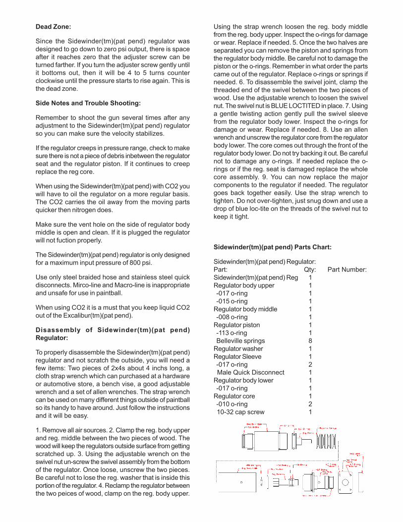
Sidewinder(tm)(pat pend) Parts Chart:
Sidewinder(tm)(pat pend) Regulator:Part: Qty: Part Number:Sidewinder(tm)(pat pend) Reg 1Regulator body upper 1 -017 o-ring 1 -015 o-ring 1Regulator body middle 1 -008 o-ring 1Regulator piston 1 -113 o-ring 1 Belleville springs 8Regulator washer 1Regulator Sleeve 1 -017 o-ring 2 Male Quick Disconnect 1Regulator body lower 1 -017 o-ring 1Regulator core 1 -010 o-ring 2 10-32 cap screw 1
Solenoid Valves
Removal of the solenoid valves:
Remove the grip frame and grip plate as one piece.Carefully pull the grip and grip plate straight away fromthe body. The grip plate locates on two pins in the markerbody.
Carefully unplug the solenoid valves from the circuitboard. Using an allen wrench, remove the screws holdingsolenoid valve you want to replace. Lift the valve straightout of the marker body. Be careful not to lose the smallo-rings that seal the solenoid to the body.
Place the o-rings back into the o-ring grooves on thebody. Place the correct solenoid valve on the solenoidvalve mounting bosses and tighten down screws. Thehammer solenoid valve cannot be installed in the boltsocket and the bolt solenoid valve cannot be installed inthe hammer socket. Do not over tighten the screws.
Plug the solenoid valve back into the circuit board andgently put the grip frame back onto the marker makingsure not to pinch any wires. Re-install the grip framescrews.
The solenoid valves used in the Excalibur(tm)(pat pend)are a custom version of an off the shelf valve and havebeen thoroughly tested for long life and durability. A setof valves used in the Excalibur(tm)(pat pend) paintballmarker have been tested to over 5,500,000 cycles andare still running. 5,500,000 cycles is equivalent toshooting 2750 cases of paint if the cases were 2000rdboxes each. One randomly picked valve cycled over20,000,000 times.
Do not try to work on the solenoid valves. Do not try toexchange parts from one solenoid to another. The partson the solenoid valves are matched to each other whenthey are assembled at the factory and can not be mixedwith other valves. If the solenoid valves parts are mixedthey may not work properly.
Trouble shooting:
Air leaking from the solenoid valve:
1. Check the o-rings sealing the valve to the body.
2. Check to see if the air is leaking through the solenoidvalve. If air is leaking through the valve, replace the valveor check the o-rings of the hammer or ram.
Trigger Frame
Adjusting the trigger pull:
There are 3 set screws for adjusting the total triggermovement: (1) forward stop, (1) rearward stop and (1)mirco-switch activation screw.
When adjusting the trigger, start with the forward andrearward trigger stops. Adjust the trigger until you havethe amount of movement you want. Then adjust themirco-switch screw until it activates the mirco-switchduring the trigger pull. Make sure to use a small amountof BLUE Loc-tite to keep the set screws from comingloose. Whenever you make any adjustments to thetrigger you should always make sure the mico-switchactivates when you pull the trigger.
**Do not remove the trigger spring. Always leave aspring in the trigger to provide positive triggerreturn.**
When adjusting the spring tension on the trigger, it isbest to leave the tension a little high so normalmovement during play will not accidentally activate thetrigger. The spring can be interchanged with those usedon Autococker trigger plates so you can personalize itto your own spring tension.
**Do not cut the trigger guard off.**
Double triggers and frames are available from AKALMP/ Leads Metal Products Inc. There is no difference inthe cost of the Excalibur(tm)(pat pend) for single or doubletrigger frames. The two style of frames can be inter-changed without any modifications to the gun.
Trouble shooting:
1. The electronics are on but the gun won’t fire. Checkto make sure that none of the trigger set screws havemoved out of adjustment.
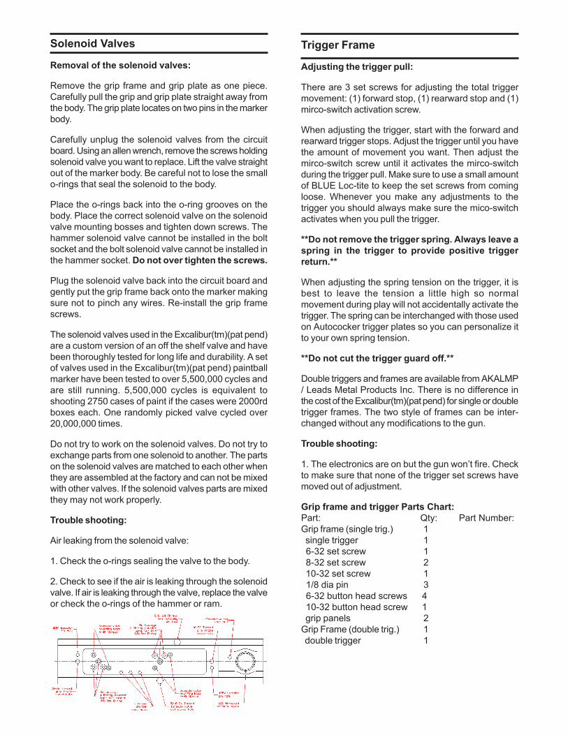
Grip frame and trigger Parts Chart:Part: Qty: Part Number:Grip frame (single trig.) 1 single trigger 1 6-32 set screw 1 8-32 set screw 2 10-32 set screw 1 1/8 dia pin 3 6-32 button head screws 4 10-32 button head screw 1 grip panels 2Grip Frame (double trig.) 1 double trigger 1
Tornado Valve
The valve used in the Excalibur(tm)(pat pend) is alsoused in the Merlin body kits and other future markers.The valve is a bigger, stronger Tornado(tm)(pat #5791328)valve which was orginally designed for the cockers. TheTornado(tm)(pat #5791328) valve has a lifetime warrentythat covers replacement of the valve unless you modifiythe valve.
Valve removal and maintenance:
Remove the valve chamber plug by unscrewing it fromthe marker body using an allen wrench. Then slide itout. The valve spring and valve stem should come outwith it. This will allow you to change the valve stem ifthere is a problem.
To remove the valve body:
With the valve chamber plug, valve spring and valve stemremoved. Unscrew the hammer from the back of theExcalibur(tm)(pat pend). Then unscrew the set screwon the side of the marker that holds the valve body inplace. Using a wood dowel rod, gently push the valvebody out either end of the marker. When reinstalling thevalve body, use a drop of BLUE Loc-tite on the set screwthat holds the valve body in the marker.
Trouble shooting:
Air leaking down the barrel:
1. Check the valve stem, it may need to be replaced.
2. Air may be leaking by the o-ring on the valve body.Take the correct size allen wrench and loosen the valveretaining set screw about a 1/4 of a turn. If the leakstops, tighten the screw back. What happens is thatthe o-ring sometimes shifts just a little and looseningthe screw allows it to shift back.
Tornado Valve(tm)(Patent #5791328) Parts Chart:
Part: Qty: Part Number:Valve Chamber endcap 1 -015 o-ring 1 5/16-24 set screw 1Valve Spring 1Valve Stem 1Valve Body 1 -015 o-ring 2