Embed Size (px)
Citation preview

USER’S MANUAL
(Standard Models)
Compact Low-noise Inverter
SYSDRIVE 3G3EV SERIES

Thank you for choosing this SYSDRIVE 3G3EV-series product. Proper useand handling of the product will ensure proper product performance, willlength product life, and may prevent possible accidents.Please read this manual thoroughly and handle and operate the productwith care.
NOTICE1. This manual describes the functions of the product and relations with other
products. You should assume that anything not described in this manual isnot possible.
2. Although care has been given in documenting the product, please contactyour OMRON representative if you have any suggestions on improving thismanual.
3. The product contains potentially dangerous parts under the cover. Do notattempt to open the cover under any circumstances. Doing so may result ininjury or death and may damage the product. Never attempt to repair or dis-assemble the product.
4. We recommend that you add the following precautions to any instructionmanuals you prepare for the system into which the product is being installed.
Precautions on the dangers of high-voltage equipment.
Precautions on touching the terminals of the product even after power hasbeen turned off. (These terminals are live even with the power turned off.)
5. Specifications and functions may be changed without notice in order to im-prove product performance.
Items to Check Before UnpackingCheck the following items before removing the product from the package:
Has the correct product been delivered (i.e., the correct model number andspecifications)?
Has the product been damaged in shipping?
Are any screws or bolts loose?

Table of Contents
i
Chapter 1. Getting Started 1-1. . . . . . . . . . . . . . . . . . . . . . . . . . 1-1 Items to be Checked when Unpacking 1-2. . . . . . . . . . . . . . . . . . . . . . . . . . . . . . 1-2 Precautions 1-3. . . . . . . . . . . . . . . . . . . . . . . . . . . . . . . . . . . . . . . . . . . . . . . . . . .
Chapter 2. Overview 2-1. . . . . . . . . . . . . . . . . . . . . . . . . . . . . . . 2-1 Features 2-2. . . . . . . . . . . . . . . . . . . . . . . . . . . . . . . . . . . . . . . . . . . . . . . . . . . . . . 2-2 Component Names 2-4. . . . . . . . . . . . . . . . . . . . . . . . . . . . . . . . . . . . . . . . . . . . .
Chapter 3. Design 3-1. . . . . . . . . . . . . . . . . . . . . . . . . . . . . . . . . 3-1 Installation 3-2. . . . . . . . . . . . . . . . . . . . . . . . . . . . . . . . . . . . . . . . . . . . . . . . . . .
3-1-1 Outside/Mounting Dimensions 3-2. . . . . . . . . . . . . . . . . . . . . . . . . . . . . . 3-1-2 Installation Conditions 3-5. . . . . . . . . . . . . . . . . . . . . . . . . . . . . . . . . . . . .
3-2 Wiring 3-7. . . . . . . . . . . . . . . . . . . . . . . . . . . . . . . . . . . . . . . . . . . . . . . . . . . . . . . 3-2-1 Terminal Blocks 3-7. . . . . . . . . . . . . . . . . . . . . . . . . . . . . . . . . . . . . . . . . . 3-2-2 Wiring Around the Main Circuit 3-11. . . . . . . . . . . . . . . . . . . . . . . . . . . . . 3-2-3 Wiring Control Circuit Terminals 3-18. . . . . . . . . . . . . . . . . . . . . . . . . . . .
Chapter 4. Preparing for Operation 4-1. . . . . . . . . . . . . . . . . . 4-1 Preparation Procedure 4-2. . . . . . . . . . . . . . . . . . . . . . . . . . . . . . . . . . . . . . . . . . . 4-2 Using the Digital Operator 4-3. . . . . . . . . . . . . . . . . . . . . . . . . . . . . . . . . . . . . . .
4-2-1 Name and Function of Each Component 4-3. . . . . . . . . . . . . . . . . . . . . . . 4-2-2 Outline of Operation 4-5. . . . . . . . . . . . . . . . . . . . . . . . . . . . . . . . . . . . . . 4-2-3 Setting Constants 4-8. . . . . . . . . . . . . . . . . . . . . . . . . . . . . . . . . . . . . . . . .
4-3 Test Run 4-25. . . . . . . . . . . . . . . . . . . . . . . . . . . . . . . . . . . . . . . . . . . . . . . . . . . . . 4-3-1 Checking Wiring 4-25. . . . . . . . . . . . . . . . . . . . . . . . . . . . . . . . . . . . . . . . . 4-3-2 Turning Power On and Checking Indicator Display 4-25. . . . . . . . . . . . . . 4-3-3 Initializing Constants 4-25. . . . . . . . . . . . . . . . . . . . . . . . . . . . . . . . . . . . . . 4-3-4 Setting a V/f Pattern 4-25. . . . . . . . . . . . . . . . . . . . . . . . . . . . . . . . . . . . . . . 4-3-5 Setting Rated Motor Amperage 4-26. . . . . . . . . . . . . . . . . . . . . . . . . . . . . . 4-3-6 Setting the Reference Frequency 4-26. . . . . . . . . . . . . . . . . . . . . . . . . . . . . 4-3-7 Operating the Inverter with the Digital Operator 4-26. . . . . . . . . . . . . . . . 4-3-8 Checking Output Frequency and Amperage 4-26. . . . . . . . . . . . . . . . . . . . 4-3-9 Checking Operation during Reverse Rotation 4-26. . . . . . . . . . . . . . . . . . . 4-3-10 Checking Operation with Mechanical System Connected 4-26. . . . . . . . . . 4-3-11 Checking Operation Performed by Controller 4-26. . . . . . . . . . . . . . . . . . .
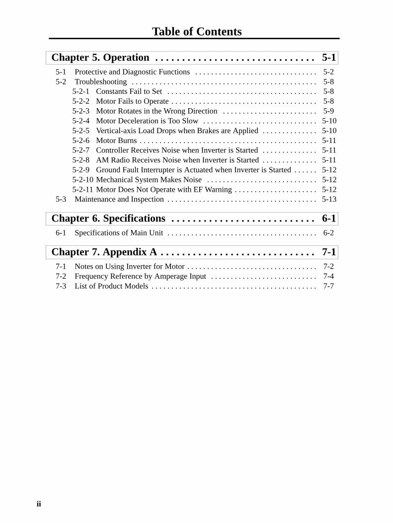
Table of Contents
ii
Chapter 5. Operation 5-1. . . . . . . . . . . . . . . . . . . . . . . . . . . . . . 5-1 Protective and Diagnostic Functions 5-2. . . . . . . . . . . . . . . . . . . . . . . . . . . . . . . 5-2 Troubleshooting 5-8. . . . . . . . . . . . . . . . . . . . . . . . . . . . . . . . . . . . . . . . . . . . . . .
5-2-1 Constants Fail to Set 5-8. . . . . . . . . . . . . . . . . . . . . . . . . . . . . . . . . . . . . . 5-2-2 Motor Fails to Operate 5-8. . . . . . . . . . . . . . . . . . . . . . . . . . . . . . . . . . . . . 5-2-3 Motor Rotates in the Wrong Direction 5-9. . . . . . . . . . . . . . . . . . . . . . . . 5-2-4 Motor Deceleration is Too Slow 5-10. . . . . . . . . . . . . . . . . . . . . . . . . . . . . 5-2-5 Vertical-axis Load Drops when Brakes are Applied 5-10. . . . . . . . . . . . . . 5-2-6 Motor Burns 5-11. . . . . . . . . . . . . . . . . . . . . . . . . . . . . . . . . . . . . . . . . . . . . 5-2-7 Controller Receives Noise when Inverter is Started 5-11. . . . . . . . . . . . . . 5-2-8 AM Radio Receives Noise when Inverter is Started 5-11. . . . . . . . . . . . . . 5-2-9 Ground Fault Interrupter is Actuated when Inverter is Started 5-12. . . . . . 5-2-10 Mechanical System Makes Noise 5-12. . . . . . . . . . . . . . . . . . . . . . . . . . . . 5-2-11 Motor Does Not Operate with EF Warning 5-12. . . . . . . . . . . . . . . . . . . . .
5-3 Maintenance and Inspection 5-13. . . . . . . . . . . . . . . . . . . . . . . . . . . . . . . . . . . . . .
Chapter 6. Specifications 6-1. . . . . . . . . . . . . . . . . . . . . . . . . . . 6-1 Specifications of Main Unit 6-2. . . . . . . . . . . . . . . . . . . . . . . . . . . . . . . . . . . . . .
Chapter 7. Appendix A 7-1. . . . . . . . . . . . . . . . . . . . . . . . . . . . . 7-1 Notes on Using Inverter for Motor 7-2. . . . . . . . . . . . . . . . . . . . . . . . . . . . . . . . . 7-2 Frequency Reference by Amperage Input 7-4. . . . . . . . . . . . . . . . . . . . . . . . . . . 7-3 List of Product Models 7-7. . . . . . . . . . . . . . . . . . . . . . . . . . . . . . . . . . . . . . . . . .

Chapter 1
Getting Started
1-1 Items to be Checked when Unpacking
1-2 Precautions
1

1-2
1-1 Items to be Checked when Unpacking
Checking the ProductOn delivery, always check that the delivered product is the SYSDRIVE 3G3EV Inverterthat you ordered.
Should you find any problems with the product, immediately contact your nearest localsales representative.
Checking the Nameplate
Inverter modelInput specifications
Output specifications
Checking the Model
3G3EV-A2002M-ESpecial Specification
Specifications
Maximum applicable motor capacity
Voltage class
Installation type
Series name: 3G3EV Series
SpecificationsBlank Standard modelM Multi-function modelR SYSMAC BUS model
Maximum Applicable MotorCapacity001 0.1 kW002 0.2 (0.37) kW004 0.4 (0.55) kW007 0.75 (1.1) kW015 1.5 kW
Note The figures in parentheses indi-cate capacities for 400-VAC classmodels.
Getting Started Chapter 1

1-3
Voltage Class2 Three-phase 200-VAC inputB Single/Three-phase 200-VAC
input
Installation Type/OptionA Panel mountingP Option
Special Specification-E English Models-CUE UL/CUL and EC Directives
ModelsBlank Japanese Models
Checking for DamageCheck the overall appearance and check for damage or scratches resulting from trans-portation.
Checking AccessoriesNote that this manual is the only accessory provided with the 3G3EV (Standard Model).Set screws and other necessary parts must be prepared by customers.
1-2 Precautions
To ensure safe operation of the 3G3EV, note the following items:
Always Hold the Heat Sink During Removal.When moving the 3G3EV, always hold the heat sink (aluminum portion on the rear of theUnit).
Heat sink
Watch Out for Residual Voltage On Charged PortionsAfter the power is turned off, residual voltage remains in the capacitor inside theInverter. Therefore, touching terminals immediately after turning the power off maycause an electrical shock.
Getting Started Chapter 1

1-4
If an inspection or some other task is to be performed, always wait at least one minutefrom the time all indicators on the front panel go off.
(Note that this warning is applicable whenever you perform any task after turning themain circuit off.)
Do Not Remove the Digital Operator When the Main Circuit isStill On.
Always turn the main circuit off before removing the digital operator.
Removing the digital operator with the main circuit ON may cause an electrical shockand damage the equipment.
Do Not Modify Wiring or Check Signals When the Main Circuitis On.
Always turn the main circuit off before modifying wiring or checking signals.
Touching terminals while the main circuit is on may cause an electrical shock and dam-age the equipment.
Do Not Conduct a Dielectric Strength Test.Because the 3G3EV Inverter is an electronic control unit using semiconductor, neverconduct a dielectric strength test or an insulation resistance test for the control circuit.
Modify Constant Settings Correctly.Always modify the constant settings according to the procedures described in thismanual.
Getting Started Chapter 1

Chapter 2
Overview
2-1 Features
2-2 Component Names
2

2-2
2-1 Features
Easy to Use
Basic Constants Displayed On IndicatorsConstants for basic operations such as frequency setting and acceleration/decelerationtime setting are displayed on dedicated indicators. Therefore, constant numbers can beconfirmed easily.
Minimum Constant Setting ItemsConstant setting items have been minimized to enable even first-time users to setconstants easily.
Easy to Install
Very Small and LightweightThe 3G3EV Inverter is approximately half the size of our Low-noise General-purposeInverters in terms of volume and weight percentage. This improves space efficiency andoperating efficiency (including easier removal).
Optional DIN TrackAn optional DIN track is available. This DIN track enables the user to mount the 3G3EVInverter on the DIN track with a one-touch operation.
Overview Chapter 2

2-3
Easy to Wire
Easy Wiring without Having to Open the Front CoverThis Inverter can be wired just by opening the terminal block cover.
Separate Input and Output Terminal BlocksPower input terminals are located in the upper section, while motor output terminals arein the lower section. In this way, the input and output terminal blocks are separated ac-cording to the contactors, so incorrect wiring can be prevented.
Soldering No Longer NecessaryNo connector means no soldering.
Easy to Operate
Switching the Operation Mode with a One-touch OperationFor example, after a test run is performed using the Digital Operator, it can be easilyswitched to a production run using control terminals with a one-touch operation.
Checking a Test Run with Various MonitorsOutput frequency, output current, and the direction of motor rotation appear in the dis-play section of the Digital Operator, so the mechanical system can be easily monitoredduring a test run.
Low NoiseAn insulated gate bipolar transistor (IGBT) power element has been adopted to elimi-nate metallic noise.
High-torque Operation Even in Low Speed RangeA torque rate of 150% can be achieved even in a low speed range where output frequen-cy is only 3 Hz. Thus, acceleration time can be reduced.
Various Input Power SuppliesA 400-VAC-class Inverter has been newly added to the 3G3EV Series to cope with vari-ous power supplies.
• Three-phase 200-VAC input: 0.1 to 1.5 kW
• Single/Three-phase 200-VAC input: 0.1 to 1.5 kW
• Three-phase 400-VAC input: 0.2 to 1.5 kW
Overview Chapter 2

2-4
2-2 Component Names
Main UnitMain Circuit Terminals (Input)Power inputterminals
Braking resistorconnection terminals
Run indicator
Alarm indicator
Control circuit terminals(output)
Ground terminal
Main Circuit Terminals (Output)
Motor outputterminals
Digital Operator
Control circuitterminals (input)
MA MB MC SF SR S1 SC FS FR FC
L1 N/L2 L3
Note This diagram shows the Inverter with all terminal block covers removed.
Overview Chapter 2

2-5
Digital Operator
Displaysection
Operationkeys
Mode Key
Increment Key
RUN Key
Data display section
Monitor item indicators
In-service item indicators (green indicators)These items can be monitored or set evenduring operation.
Stopped item indicators (red indicators)These items can be set only when theInverter is stopped.
Constant item indicators
Enter Key
Decrement Key
STOP/RESET Key
Overview Chapter 2

Chapter 3
Design
3-1 Installation
3-2 Wiring
3

3-2
3-1 Installation
3-1-1 Outside/Mounting Dimensions
Note All dimensions are in millimeters.
3G3EV-A2001(-) to 3G3EV-A2004(-) (0.1 to 0.4 kW): Three-phase 200-VAC Input
3G3EV-AB001(-) to 3G3EV-AB002(- ) (0.1 to 0.2 kW): Single/Three-phase 200-VAC Input
4.5 dia.
Note 1. For the 3G3EV-A2001(-), 3G3EV-A2002(-), and 3G3EV-AB001(-), a U-shaped notch (4.5 mm wide) is provided instead of the upper mounting hole (4.5mm in diameter).
Note 2. Install the Inverter with two M4 bolts.
Design Chapter 3

3-3
Three-phase 200-VAC Input Model3G3EVmodel
Output W H D W1 H1 T Weight(kg)
A2001(-) 0.1 kW 68 128 75 56 118 3 Approx.0.5
A2002(-) 0.2 kW 88 3 Approx.0.6
A2004(-) 0.4 kW 110 5 Approx.0.9
Single/Three-phase 200-VAC Input Model3G3EVmodel
Output W H D W1 H1 T Weight(kg)
AB001(-) 0.1 kW 68 128 75 56 118 3 Approx.0.5
AB002(-) 0.2 kW 108 3 Approx.0.6
Design Chapter 3

3-4
3G3EV-A2007(-) to 3G3EV-A2015(-) (0.75 to 1.5 kW): Three-phase 200-VAC Input3G3EV-AB004(-) to 3G3EV-AB015(- ) (0.4 to 1.5 kW): Single/Three-phase 200-VAC Input3G3EV-A4002(-) to 3G3EV-A4015(-) (0.2 to 1.5 kW): Three-phase 400-VAC Input
Two, 4.5 dia.
Note Install the Inverter with four M4 bolts.
Three-phase 200-VAC Input Model3G3EVmodel
Output W H D W1 H1 Weight (kg)
A2007(-) 0.75 kW 108 128 130 96 118 Approx. 1.3
A2015(-) 1.5 kW 155 Approx. 1.5
Single/Three-phase 200-VAC Input Model3G3EVmodel
Output W H D W1 H1 Weight(kg)
AB004(-) 0.4 kW 108 128 130 96 118 Approx. 1.3
AB007(-) 0.75 kW Approx. 1.3
AB015(-) 1.5 kW 130 170 118 Approx. 2.0
Design Chapter 3

3-5
Three-phase 400-VAC Input Model3G3EVmodel
Output W H D W1 H1 Weight(kg)
A4002(-) 0.2 kW 108 128 92 96 118 Approx. 1.0
A4004(-) 0.4 kW 110 Approx. 1.0
A4007(-) 0.75 kW 140 Approx. 1.5
A4015(-) 1.5 kW 130 170 118 Approx. 2.0
3-1-2 Installation Conditions
Installation Site• Install the Inverter under the following conditions:
Ambient temperature for operation: –10°C to 50°CHumidity: 90% RH or less (non-condensing)
• Install the Inverter in a clean location free from oil mist and dust. Alternatively, install itin a totally enclosed panel that is completely shielded from suspended dust.
• When installing or operating the Inverter, always take special care so that metal pow-der, oil, water, or other foreign matter do not get in the Inverter.
• Do not install the Inverter on inflammables such as wood.
Direction of Installation• Install the Inverter on a vertical surface so that the characters on the nameplate areoriented upward.
Installation Space• When installing the Inverter, always provide the following installation space to allownormal heat dissipation from the Inverter:
W= 30 mm min. 100 mm min.
100 mm min.
Air
Side
Air
Inve
rter
Inve
rter
Inve
rter
Design Chapter 3

3-6
Ambient Temperature Control• To enhance operation reliability, the Inverter should be installed in an environment freefrom extreme temperature rises.
• If the Inverter is installed in an enclosed environment such as a box, use a cooling fanor air conditioner to maintain the internal air temperature below 50°C.
• The surface temperature of the Inverter may reach 30°C higher than the ambient tem-perature. Therefore, keep all thermally susceptible devices and wires away from theInverter.
Protecting the Inverter from Foreign Matter during Installation• Place a cover over the Inverter to shield it from metal powder produced by drilling dur-ing installation.
(Upon completion of installation, always remove the cover from the Inverter. Other-wise, ventilation will be affected, causing the invert to overheat.)
Design Chapter 3

3-7
3-2 Wiring
3-2-1 Terminal Blocks
Name of Each Terminal Block
Main Circuit Terminals (Input)
Power inputterminals
Braking resistorconnection terminals
Control circuitterminals (output)
Groundterminal
Main circuit terminals(output)
Motor Output Terminals (Output)
Control circuitterminals (input)
MA MB MC SF SR S1 SC FS FR FC
Note This diagram shows an Inverter with all terminal block covers removed.
Design Chapter 3
3-8
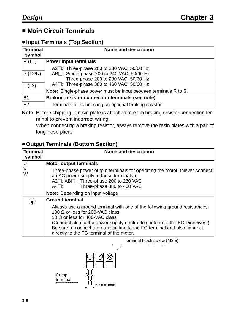
Main Circuit Terminals
Input Terminals (Top Section)Terminalsymbol
Name and description
R (L1) Power input terminalsA2: Three-phase 200 to 230 VAC, 50/60 Hz
S (L2/N)A2: Three hase 200 to 230 VAC, 50/60 HzAB: Single-phase 200 to 240 VAC, 50/60 Hz
Three-phase 200 to 230 VAC, 50/60 HzA4 Th h 380 460 VAC 0/60 HT (L3)
,A4: Three-phase 380 to 460 VAC, 50/60 Hz
Note: Single-phase power must be input between terminals R to S.B1 Braking resistor connection terminals (see note)B2
g ( )Terminals for connecting an optional braking resistor
Note Before shipping, a resin plate is attached to each braking resistor connection ter-minal to prevent incorrect wiring.When connecting a braking resistor, always remove the resin plates with a pair oflong-nose pliers.
Output Terminals (Bottom Section)Terminalsymbol
Name and description
UVW
Motor output terminalsThree-phase power output terminals for operating the motor. (Never connectan AC power supply to these terminals.)A2, AB: Three-phase 200 to 230 VACA4: Three-phase 380 to 460 VAC
Note: Depending on input voltageGround terminal
Always use a ground terminal with one of the following ground resistances: 100 Ω or less for 200-VAC class10 Ω or less for 400-VAC class.(Connect also to the power supply neutral to conform to the EC Directives.) Be sure to connect a grounding line to the FG terminal and also connectdirectly to the FG terminal of the motor.
6.2 mm max.
Terminal block screw (M3.5)
Crimpterminal
Design Chapter 3

3-9
Control Circuit Terminals
Input Terminals (On Right-hand Side)No external power supply is required because a built-in power supply is provided.
Terminalsymbol
Name and description Interface
SF Forward/StopWhen the terminal is ON, the motor rotates inthe forward direction. When the terminal is OFF,the motor stops.
SR Reverse/StopWhen the terminal is ON, the motor reverses.When the terminal is OFF, the motor stops.
24 VDC, 8 mA
(See note 3)S1 Multi-function input (see note 1)
(See note 3)
SC Sequence input commonInput terminal common to SF, SR, and S1
FS Frequency reference power supplyOutput voltage: 12 VDCPermissible amperage: 20 mA
FR Frequency reference input (see note 2)0 to 10 VDC is input. Input impedance
FC Frequency reference commonIn ut im edance
Note 1. Constant No. 06 (n06) is used to set this function. This constant is factory-set to“fault reset.”
Note 2. FR can be switched to an amperage input terminal (4 to 20 mA) by setting theinternal DIP switch and constant No. 02 (operation mode selection). For details,refer to 7-2 Frequency Reference by Amperage Input.
Note 3. The circuit for a 400-VAC-class Inverter is as shown below.
GND
24 V
GND
3.3 K
SW2
SF
SR
S1 to S3
SC360
0.1µ
Design Chapter 3

3-10
Output Terminals (On Left-hand Side)Terminalsymbol
Name and description Interface
MA Multi-function contact output (contact a)(see note)
MB Multi-function contact output (contact b)(see note)
30 VDC
MC Multi-function contact output (common) 250 VAC
Note Constant No. 09 (n09) is used to set the function. This constant is factory set to“operation in progress.”
Standard Connection Diagram
Molded-case circuitbreaker (MCCB)
Forward/Stop
Reverse/Stop
Multi-function input
Sequence input common
Frequencyreferencerheostat(2 kΩ,1/4 W min.)
Braking resistor (option)
Multi-function contact output(Contact a)
(Contact b)
Common
L1
N/L2
L3
Power supply:Three-phase, 200 to 230 VAC,50/60 Hz Three-phase, 380 to 460 VAC, 50/60 Hz
Design Chapter 3

3-11
Note 1. If a 3G3EV-AB is used in single-phase input mode, single-phase 200 to240 VAC power with a frequency of 50/60 Hz must be input between terminalsR and S.
Note 2. For the 3-wire sequence, refer to the wiring on page 4-12.
Note 3. The input sequence power is built in.
3-2-2 Wiring Around the Main Circuit
System reliability and noise resistance are affected by the wiring methodused. Therefore, always follow the instructions given below when connect-ing the Inverter to peripheral devices and other parts.
Wire Size and Molded-Case Circuit Breaker to be UsedFor the main circuit and ground, always use 600-V polyvinyl chloride (PVC) cables.
If the cable is long and may cause voltage drops, increase the wire size according to thecable length.
Model Terminalsymbol
Terminalscrew
Wire size(mm2)
Molded-casecircuit breaker
capacity (A)3G3EV-A2001(-) R S T B1 B2 M3.5 0.75 to 2 10
3G3EV-AB001(-) U V W 5
3G3EV-A2002(-) R S T B1 B2 M3.5 0.75 to 2 5
3G3EV-AB002(-) U V W3G3EV-A4002(-)
U
3G3EV-A2004(-) R S T B1 B2 M3.5 0.75 to 2 5
3G3EV-AB004(-) U V W3G3EV-A4004(-)
U
3G3EV-A2007(-) R S T B1 B2 M3.5 0.75 to 2 10
3G3EV-AB007(-) U V W 20
3G3EV-A4007(-)U
5
3G3EV-A2015(-) R S T B1 B2 M3.5 0.75 to 2 10
3G3EV-AB015(-) U V W 1.25 to 2 20
3G3EV-A4015(-)U
0.75 to 2 10
Note Tighten the M3.5 terminal screw to the torque of 0.8 N m.
Design Chapter 3

3-12
Determining the Wire SizeDetermine the wire size for the main circuit so that line voltage drop is within 2% of therated voltage.
Line voltage drop VD is calculated as follows:
VD (V) = 3 x wire resistance (Ω/km) x wire length (m) x amperage (A) x 10–3
Wiring on the Input Side of Main Circuit
Installing a Molded-case Circuit BreakerAlways connect the power input terminals (R, S, and T) and power supply via a molded-case circuit breaker. Power must be supplied instantaneously. Unstable power startupwill not start the Inverter.
Installing a Ground Fault InterrupterIf a ground fault interrupter is to be connected to the wire on the primary side (R, S, andT) of the main circuit, use either of the following interrupters to prevent malfunctions:
• Ground fault interrupter with a sensitivity amperage of 200 mA or more and with anoperating time of 0.1 second or more
• Ground fault interrupter with high-frequency countermeasures (for Inverter)
Installing a Magnetic ContactorThis Inverter can be used without a magnetic contactor (MC) on the power supply side.
If the power supply for the main circuit is to be shut off because of the sequence, a mag-netic contactor can be used instead of a molded-case circuit breaker.
However, when a magnetic contactor is installed on the primary side of the main circuitto forcibly stop a load, note that regenerative braking does not work and the load coaststo a stop.
• A load can be started and stopped by opening and closing the magnetic contactor onthe primary side. Note, however, that frequently opening and closing the magneticcontactor may cause the Inverter to break down.
• When the Inverter is operated with a Digital Operator, automatic operation cannot beperformed after recovery from a power interruption.
Connecting Input Power Supply to the Terminal BlockBecause the phase sequence of input power supply is irrelevant to the phase sequence(R, S, T) of the terminal block, input power supply can be connected to any terminal onthe terminal block.
Design Chapter 3

3-13
Installing an AC ReactorIf the Inverter is connected to a large-capacity power transformer (600 kW or more) orthe phase advance capacitor is switched, an excessive peak current may flow throughthe input power circuit, causing the converter unit to break down. To prevent this, installan optional AC reactor on the input side of the Inverter. This also improves the powerfactor on the power supply side.
Installing a Surge AbsorberAlways use a surge absorber or diode for the inductive loads to be connected to theInverter. These inductive loads include magnetic contactors, electromagnetic relays,solenoid valves, solenoids, and magnetic brakes.
Wiring of Braking Resistor/Braking Resistor UnitWhen using an Inverter for loads with a large inertia or for vertical axis loads, regenera-tive energy will be fed back.If the regenerative energy exceeds the Inverter capacity, overvoltage will be detected inthe main circuit. In such a case, use a Braking Resistor or Braking Resistor Unit.
Note Be sure to create a sequence that will turn OFF the Inverter power supply whenresistor overheating occurs. When using a Braking Resistor, be sure to install athermal relay to detect resistor overheating. When using a Braking Resistor Unit,use an error output contact. Otherwise, a fire may occur.
3G3EV Model Braking Resistor (Duty Cycle 3%ED)
Braking ResistorUnit
(Duty Cycle 10%ED)
Minimumconnectedresistance
A2001(-)/AB001(-) 3G3IV-PERF150WJ401(400 Ω)
--- 200 ΩA2002(-)/AB002(-) (400 Ω) 200 ΩA2004(-)/AB004(-) 3G3IV-PERF150WJ201
(200 Ω)3G3IV-PLKEB20P7 (200 Ω 70 W)
200 ΩA2007(-)/AB007(-) (200 Ω) (200 Ω 70 W) 80 ΩA2015(-)/AB015(-) 3G3IV-PERF150WJ101
(100 Ω)3G3IV-PLKEB21P5 (100 Ω 260 W)
60 Ω
A4002(-)/A4004(-) 3G3IV-PERF150WJ751(750 Ω)
3G3IV-PLKEB40P7 (750 Ω 70 W)
750 ΩA4007(-) (750 Ω) (750 Ω 70 W) 510 ΩA4015(-) 3G3IV-PERF150WJ401
(400 Ω)3G3IV-PLKEB41P5 (400 Ω 260 W)
240 Ω
Note Do not use a Resistor whose resistance is below the minimum connected resis-tance. Otherwise, the Inverter will be damaged.
Design Chapter 3

3-14
Installing a Noise Filter on the Power Supply SideInstall a noise filter to eliminate noise transmitted between the power line and theInverter.
Wiring Example 1
3G3IV-PHF 3G3EVPowersupply
Noisefilter
SYSMAC,etc.
Other controllers
Note Use a special-purpose noise filter for Inverters.
Wiring Example 2
3G3EV
General-purposenoise filter
Powersupply
SYSMAC,etc.
Other controllers
3G3EVPowersupply
General-purposenoise filter
SYSMAC,etc.
Other controllers
Note Do not use a general-purpose noise filter.
Wiring on the Output Side of Main Circuit
Connecting the Terminal Block to the LoadConnect output terminals U, V, and W to motor lead wires U, V, and W, respectively.
Design Chapter 3
3-15
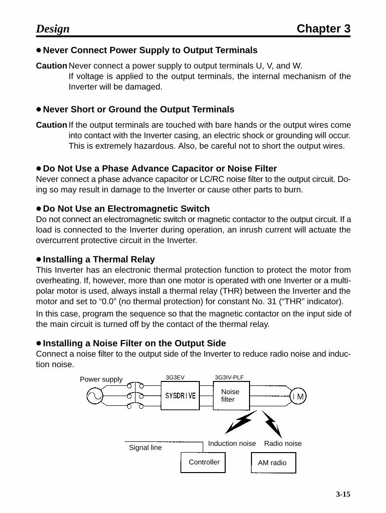
Never Connect Power Supply to Output Terminals
Caution Never connect a power supply to output terminals U, V, and W.If voltage is applied to the output terminals, the internal mechanism of theInverter will be damaged.
Never Short or Ground the Output Terminals
Caution If the output terminals are touched with bare hands or the output wires comeinto contact with the Inverter casing, an electric shock or grounding will occur.This is extremely hazardous. Also, be careful not to short the output wires.
Do Not Use a Phase Advance Capacitor or Noise FilterNever connect a phase advance capacitor or LC/RC noise filter to the output circuit. Do-ing so may result in damage to the Inverter or cause other parts to burn.
Do Not Use an Electromagnetic SwitchDo not connect an electromagnetic switch or magnetic contactor to the output circuit. If aload is connected to the Inverter during operation, an inrush current will actuate theovercurrent protective circuit in the Inverter.
Installing a Thermal RelayThis Inverter has an electronic thermal protection function to protect the motor fromoverheating. If, however, more than one motor is operated with one Inverter or a multi-polar motor is used, always install a thermal relay (THR) between the Inverter and themotor and set to “0.0” (no thermal protection) for constant No. 31 (“THR” indicator).
In this case, program the sequence so that the magnetic contactor on the input side ofthe main circuit is turned off by the contact of the thermal relay.
Installing a Noise Filter on the Output SideConnect a noise filter to the output side of the Inverter to reduce radio noise and induc-tion noise.
3G3EV 3G3IV-PLFPower supply
Noisefilter
Signal line
Controller
Induction noise Radio noise
AM radio
Design Chapter 3

3-16
Induction Noise: Electromagnetic induction generates noise on the signal line, causingthe controller to malfunction.
Radio Noise: Electromagnetic waves from the Inverter and cables cause thebroadcasting radio receiver to make noise.
How to Prevent Induction NoiseAs described above, a noise filter can be used to prevent induction noise from beinggenerated on the output side. Alternatively, cables can be routed through a groundedmetal pipe to prevent induction noise. Keeping the metal pipe at least 30 cm away fromthe signal line considerably reduces induction noise.
3G3EV
30 cm min.
MCCB Metal pipePower supply
Signal line
Controller
How to Prevent Radio NoiseRadio noise is generated from the Inverter as well as the input and output lines. To re-duce radio noise, install noise filters on both input and output sides, and also install theInverter in a totally enclosed steel box.
The cable between the Inverter and the motor should be as short as possible.
3G3EVPower supply
Steel box
Noisefilter
Noisefilter
Metal pipe
Design Chapter 3

3-17
Cable Length between Inverter and MotorIf the cable between the Inverter and the motor is long, the high-frequency leakage cur-rent will increase, causing the Inverter output current to increase as well. This may affectperipheral devices. To prevent this, adjust the carrier frequency (set in n37) as shown inthe table below.
Cable length between Inverter and motor 50 m max. 100 m max.Carrier frequency (n37) 10 kHz max. (1, 2, 3, 4) 5 kHz max. (1, 2)
Ground Wiring• Always use a ground terminal with the following ground resistance.200-VAC Class: 100 Ω or less 400-VAC Class: 10 Ω or less
• For 400-VAC-class models that conform to EC Directives, also connect to the neutralof the power supply.
• Do not share the ground wire with other devices such as a welder or power tool.
• Always use a ground wire that complies with technical standards on electrical equip-ment. Route the ground wire so that the total length is as short as possible.
• When using more than one Inverter, be careful not to loop the ground wire.
Design Chapter 3

3-18
3-2-3 Wiring Control Circuit Terminals
The control signal line must be 50 m or less and must be separated fromthe power line. If frequency references are input externally, use a twisted-pair shielded line.
Wiring Sequence Input/Output TerminalsWire the sequence input terminals (SF, SR, S1, and SC) and the multi-function contactoutput terminals (MA, MB, and MC) as described below.
Wires to be UsedWire type Wire size Wire to be used
Single wire 0.5 to 1.25 mm2 Polyethylene-shielded cableStranded wire 0.5 to 0.75 mm2
y y
Wiring Method• Wire each terminal as follows:
a) Loosen the terminal screw with a thin-slotted screwdriver.
b) Insert the wire from underneath the terminal block.
c) Tighten the terminal screw firmly.
• Always separate the control signal line from the main circuit cables and other powercables.
Thin-slotted screwdriver
Length ofstripped portion:Approx. 5.5 mm
Wire
Control circuitterminal block
Do not solder this portion. (Otherwise, faulty contact may result.)
Wiring Frequency Reference Input TerminalsIf frequency references are input using a D/A unit (digital-to-analog converter) or exter-nal power supply, wire the frequency reference input terminals (FR and FC) as de-scribed below.
Design Chapter 3

3-19
Wires to be UsedAlways use twisted-pair shielded wires to prevent malfunctions due to noise.
Wire type Wire size Wire to be usedSingle wire 0.5 to 1.25 mm2 Polyethylene-insulated cable forStranded wire 0.5 to 1.25 mm2
y yinstrumentation (with shield)
Wiring Method• The wiring procedure is the same as for sequence input/output terminals, describedpreviously.
• Always separate the cables from the main circuit cables and other power cables.
• Connect the shield to the ground terminal of the Inverter. Do not connect to the control-ler.
• Insulate the shield with tape to prevent it from coming into contact with other signallines and devices.
Tightening Torque of Control Circuit TerminalsTighten the control circuit terminals to the torque of 0.5 N m which is the same torqueas for the M3 screws.
Note 1. Applying a torque of greater than 0.5 N m may damage the terminal block.
Note 2. If the tightening torque is insufficient, wires may be disconnected.
Design Chapter 3

Chapter 4
Preparing forOperation
4-1 Preparation Procedure
4-2 Using the Digital Operator
4-3 Test Run
4

4-2
4-1 Preparation Procedure
1. Installation:
Install the Inverter according to installation conditions. Refer to page 3-2.
Check that all the installation conditions are met.
2. Wiring:
Connect the Inverter to power supply and peripheral devices. Refer to page 3-7.
Select peripheral devices that meet the specifications, and wire them correctly.
3. Turning the Power On:
Check the necessary items, then turn the power on.
Always check that the power voltage is correct and the power input terminals (R, S,and T) are wired correctly.
Power voltage
200-VAC class: Three-phase, 200 to 230 VAC, 50/60 Hz400-VAC class: Three-phase, 380 to 460 VAC, 50/60 Hz
When a 3G3EV-AB is used in single-phase input mode, the power voltagemust be as follows: single-phase, 200 to 240 VAC, 50/60 Hz (use terminals R andS)
Check that the motor output terminals (U, V, and W) and motor are connected cor-rectly.
Check that the control circuit terminals and controller are connected correctly.
4. Checking Display Status:
Check the Inverter for errors.
If everything is normal, the indicators below become as follows when the power isturned on:
RUN indicator: Flashing
ALARM indicator: Not lit
Constant item indicators: “FREF,” “FOUT,” or “IOUT” is lit.
Data display: Data corresponding to the constant item indicators is displayed.
If an error exists, the ALARM indicator lights up. In this case, take the necessary ac-tion as described in Section 5 Operation.
5. Setting Constants:
Use the Digital Operator to set constants required for operation. Refer to page 4-3.
Specify each constant as described in this manual.
Preparing for Operation Chapter 4

4-3
6. Test Run:
Perform a no-load test run and an actual loading test run to check that the motor andperipheral devices operate normally. Refer to page 4-25.
Check the direction of motor rotation and check that the limit switches operate nor-mally. Operate the Inverter with the Digital Operator first, then with the controller.
7. Production Run:
The Inverter is ready to run. If any error has occurred, refer to Section 5 Operation.
4-2 Using the Digital Operator
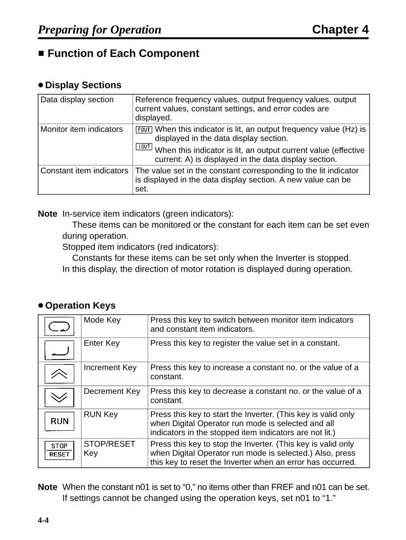
4-2-1 Name and Function of Each Component
Name of Each Component
Displaysection
Operationkeys
Mode Key
Increment Key
RUN Key
Data display section
Monitor item indicators
In-service item indicators (green indicators)These items can be monitored or set evenduring operation.
Stopped item indicators (red indicators)These items can be set only when theInverter is stopped.
Constant item indicators
Enter Key
Decrement Key
STOP/RESET Key
Preparing for Operation Chapter 4
4-4
Function of Each Component
Display SectionsData display section Reference frequency values, output frequency values, output
current values, constant settings, and error codes aredisplayed.
Monitor item indicators When this indicator is lit, an output frequency value (Hz) isdisplayed in the data display section.
When this indicator is lit, an output current value (effectivecurrent: A) is displayed in the data display section.
Constant item indicators The value set in the constant corresponding to the lit indicatoris displayed in the data display section. A new value can beset.
Note In-service item indicators (green indicators):These items can be monitored or the constant for each item can be set even
during operation.Stopped item indicators (red indicators):
Constants for these items can be set only when the Inverter is stopped.In this display, the direction of motor rotation is displayed during operation.
Operation KeysMode Key Press this key to switch between monitor item indicators
and constant item indicators.
Enter Key Press this key to register the value set in a constant.
Increment Key Press this key to increase a constant no. or the value of aconstant.
Decrement Key Press this key to decrease a constant no. or the value of aconstant.
RUN Key Press this key to start the Inverter. (This key is valid onlywhen Digital Operator run mode is selected and allindicators in the stopped item indicators are not lit.)
STOP/RESETKey
Press this key to stop the Inverter. (This key is valid onlywhen Digital Operator run mode is selected.) Also, pressthis key to reset the Inverter when an error has occurred.
Note When the constant n01 is set to “0,” no items other than FREF and n01 can be set.If settings cannot be changed using the operation keys, set n01 to “1.”
Preparing for Operation Chapter 4

4-5
4-2-2 Outline of Operation
Switching Data Display during Operation
Press the Mode Key to switch data display.During operation, only the items in the in-service item indicators sectioncan be monitored and the constants for these items can be set.If the power is turned off when the FOUT or IOUT indicator is lit, the sameindicator lights up next time the power is turned on. Otherwise, the FREFindicator always lights up.
Example ofdata display
Indicator Description
Reference frequency (Hz)
Output frequency monitoring(Hz)
Output current monitoring(effective current: A)
Acceleration time(seconds)
Deceleration time(seconds)
Forward/Reverse rotation selection
f%r: Forward rotationreU: Reverse rotation
60.0
60.0
0.2
10.0
10.0
f%r
Preparing for Operation Chapter 4

4-6
Switching Data Display when Inverter is Stopped
Press the Mode Key to switch data display.When the Inverter is stopped, all items can be monitored and the constantfor each item can be set.
Exampleof datadisplay
Indi-cator
Description
Output frequencymonitoring (Hz)
Output current monitoring(effective current: A)
Acceleration time(seconds)
Deceleration time(seconds)
Forward/Reverse rotation selection
f%r: Forward rotation reU: Reverse rotation
Maximum frequency (Hz)
Maximum voltage (V)
Maximum voltagefrequency (Hz)
Electronic thermalreference current (A)
Operationmode selection
Constant no.
Referencefrequency (Hz)
Note The indicators displayedwhen the power isturned on are the sameas shown in the previoussection “Switching DataDisplay during Opera-tion.”
60.0
10.0
0.6
10.0
f%r
60.0
200
1
n01
60.0
n02
n04
0.0
0.0
Preparing for Operation Chapter 4

4-7
Monitor Display
The 3G3EV allows the user to monitor the reference frequency, output fre-quency, output current, and the direction of rotation.
Operation MethodKey
operationIndicator Example of
data displayDescription
60.0Press the Mode Key until the FREF indicatorlights up. The reference frequency (Hz) isdisplayed.
60.0Press the Mode Key. The output frequency (Hz) isdisplayed.
0.2Press the Mode Key. The output current value(effective current: A) is displayed.
Note 1. The direction of rotation can be always monitored during operation. The indica-tors in the lower two rows of the display section flash indicating the direction ofrotation. The indicator flashing speed varies according to the speed of rotation.
Indicator flashing sequenceduring forward rotation
The indicators flashcounterclockwise when the motorrotates in the forward direction.
Note 2. The constant item indicators section has the F/R indicator, but this indicator isused to indicate a command when the Inverter is operated with the Digital Oper-ator.
Preparing for Operation Chapter 4

4-8
4-2-3 Setting Constants
The 3G3EV (Standard Model) allows the user to set 18 different constants.The constants for basic operations are allocated to dedicated indicators,so the user need not refer to the constant nos. The constants allocated todedicated indicators can be also set by lighting the PRGM indicator.Note that the operation methods using dedicated indicators and the PRGMindicator are different.
Setting Constants
Setting Constants Using a Dedicated Indicator
Example:Changing acceleration time from 10 seconds to 50 seconds.
Keyoperation
Indicator Example ofdata display
Explanation
10.0Press the Mode Key until the ACC indicator lightsup.
Flashing
10.1
Press the Increment Key. The data display sectionflashes (indicating that the data is yet to beregistered).
Flashing
50.0
Press the Increment Key until “50.0” appears inthe data display section. Holding down the keychanges data quickly.
50.0Press the Enter Key to complete the settingprocedure.
10.0 50.0 50.0
Flashing
Note If the new data is not to be registered, press the Mode Key instead of the EnterKey. The new data becomes invalid and the next item is displayed.
Preparing for Operation Chapter 4

4-9
Setting Constants Using the PRGM Indicator
Example:Changing the value of constant no. 02 (operation mode selection) to “2.”
Keyoperation
Indicator Example ofdata display
Explanation
n01Press the Mode Key until the PRGM indicatorlights up.
n02Press the Increment Key. “n02” appears in thedata display section.
0Press the Enter Key. The value of constant no. 02is displayed.
Flashing
2
Change the value to “2” by pressing the IncrementKey. The data display section flashes (indicatingthat the value is yet to be registered).
2Press the Enter Key. The data display sectionstops flashing.
n02After approximately 0.5 second, the data displaysection returns to the constant no. display (“n02”).
n022n02n01 20
Flashing
(After 0.5second)
Note 1. If the new data is not to be registered, press the Mode Key instead of the EnterKey. The new data becomes invalid and the constant no. display (“n02”) is re-turned.
Note 2. Holding down the Increment Key or Decrement Key changes data quickly.
Preparing for Operation Chapter 4

4-10
List of Constants
Constantno.
Dedicatedindicator
Description Setting range Factory setting
n01 Constant write-inhibit selec-tion/constant initialization
0, 1, 8, 9 1
n02 Operation mode selection 0 to 5 0
n03 Interruption mode selection 0, 1 0
n04 Forward/reverse rotationselection
For, rEv For
n06 Multi-function input selec-tion
0 to 4 1
n09 Multi-function output selec-tion
0, 1, 2 1
n11 Frequency reference 1 0.0 to 400 6.0 (Hz)
n12 Frequency reference 2 0.0 to 400 0.0 (Hz)
n20 Acceleration time 0.0 to 999 10.0 (seconds)
n21 Deceleration time 0.0 to 999 10.0 (seconds)
n24 Maximum frequency 50.0 to 400 60.0 (Hz)
n25 Maximum voltage 1 to 255 (see note 1)
200 (V) (see note 1)
n26 Maximum voltage frequency 1.6 to 400 60.0 (Hz)
n31 Electronic thermal referencecurrent
0.0 to see note 2 See note 2
n33 Stall prevention during de-celeration
0, 1 0
n36 Operation after recoveryfrom power interruption
0, 1, 2 0
n37 Carrier frequency 1, 2, 3, 4 (see note 3)
4 (see note 4)
n39 Frequency reference gain 0.10 to 2.55 1.00
n40 Frequency reference bias –99 to 99 0 (%)
n61 Stop Key selection 0, 1 0
n64 Operator’s frequency set-ting method
0, 1 0
n68 Error history (Display only)
Note 1. The upper limit of the setting range and the factory setting for the 400-VAC classare double the above values.
Preparing for Operation Chapter 4

4-11
Note 2. The setting range and factory setting for n31 (electronic thermal reference cur-rent) depend on the Inverter model. For details, refer to page 4-19.Normally, set the rated motor amperage in n31.
Note 3. The setting range for the 400-VAC models is “1 to 5.”
Note 4. The factory setting for the 3G3EV-A4015-CUE is “3.”
Note 5. Displaying the constant no. corresponding to an indicator in the “Dedicatedindicator” column lights the indicator.
Note 6. Constant no. 02 (n02) and subsequent constants can be set only whenconstant no. 01 (n01) is set to 1.
Constants in the shaded areas in the above table may not be usable depending on thePROM number (software version).
Con-stant
PROM no. (software version)stantno. 199 or lower 200 220 or higher
n03 No Yes Yesn39 Setting range: 0.10 to 2.00 Setting range: 0.10 to 2.00 Setting range: 0.10 to 2.55n61 No Yes Yesn64 No No Yes
Note “Yes” indicates that the constant can be set.“No” indicates that the constant cannot be set.
Details of Each Constant
n01 Constant Write-Inhibit Selection/Constant InitializationSetting range 0, 1, 8, 9 Factory setting 1
One of the following four values can be selected:
Value Description0 Only n01 can be set.1 Constants n01 to n68 can be displayed and set.8 All constants are returned to factory settings.9 The Inverter is initialized in 3-wire sequence mode.
Note 1. If other constants are to be set, always set “1” in n01.
Note 2. Setting “9” (3-wire sequence mode) in n01 allows the user to start and stop theInverter with automatic recovery type push-button switches.
Preparing for Operation Chapter 4

4-12
Example of 3-wire Sequence Mode
Stopswitch(contact b)
Runswitch(contact a)
Run command (starts Inverter when “closed”)
Stop command (stops Inverter when “opened”)
Forward/Reverse rotation command (rotatesmotor in forward direction when “opened”;rotates motor in reverse direction when “closed”)Common
Example of Operation
Forward rotation
Motor operation
Reverse rotation
Run command
Stop command
Forward/Reverserotation command
n02 Operation Mode SelectionSetting range 0 to 5 Factory setting 0
This constant is used to specify whether the Inverter is to be operated with a DigitalOperator or external signals.
Value Run command Frequency reference DIP switch setting0 Digital Operator Digital Operator (n11) OFF1 Control terminal Digital Operator (n11) OFF2 Digital Operator Control terminal (voltage input) OFF3 Control terminal Control terminal (voltage input) OFF4 Digital Operator Control terminal (amperage input) ON5 Control terminal Control terminal (amperage input) ON
Note 1. The above setting operation can be performed when constant no. 02 is se-lected. This operation is also possible when the dedicated indicator (“MODE”)is lit.
Preparing for Operation Chapter 4

4-13
Note 2. The DIP switch is located inside the Inverter. Use this switch to change the set-ting when frequency references are to be input in terms of amperage (4 to 20mA). For details, refer to Section 7-2 Frequency Reference by Amperage Input.For voltage input, never set the DIP switch to ON. Doing so may damage theequipment.
n03 Interruption Mode SelectionSetting range 0, 1 Factory setting 0
This constant is used to specify the interruption mode when the STOP/RESET Key ispressed or the operation command is OFF.
Value Description0 Frequency deceleration stop1 Free running
Example of Frequency Deceleration Stop
Output frequency
Forward rotation(Reverse rotation)
Operation command
Deceleration time 1
Minimum output frequency determinedwith constant set in n29: Factory-set to1.5 kHz
Time
Interruption DC control time determinedwith constant set in n47: Factory-set to 0.5secondON
OFF
(n21)
Example of Free Running
Output frequencyInertia of motor
Time
Forward rotation(Reverse rotation)
Operation command
ON
OFF
Note This constant is available for models with a PROM number (software version) of“200” or higher.
Preparing for Operation Chapter 4

4-14
n04 Forward/Reverse Rotation SelectionSetting range f%r , reU Factory setting f%r
(forward rota-tion)
This constant is used to specify the direction of motor rotation when the Inverter is oper-ated with the Digital Operator.
Value Descriptionf%r Forward rotationreU Reverse rotation
Note 1. While the Inverter is being operated with the Digital Operator, the direction ofmotor rotation can be changed by lighting the F/R indicator with the Mode Keyfirst, pressing the Increment or Decrement Key to change the setting, thenpressing the Enter Key.
Note 2. The direction (forward/reverse) of motor rotation depends on the motor modelused. Refer to the instruction manual for the motor.
n06 Multi-Function Input SelectionSetting range 0 to 4 Factory setting 1
One of the following values can be selected for the multi-function input (S1) function:
Value Description0 Forward/reverse rotation command (3-wire sequence)1 Fault reset (fault reset when ON)2 External fault (contact a: external fault when ON)3 External fault (contact b: external fault when OFF)4 Multi-step speed command (frequency reference 2 when ON)
n09 Multi-Function Output SelectionSetting range 0, 1, 2 Factory setting 1
One of the following three values can be specified for the multi-function contact output(MA and MB) function. When the Inverter enters the state corresponding to the specifiedvalue, MA is turned on and MB is turned off.
Value Description0 Fault occurrence1 Operation in progress (frequency reference is being output)2 Frequency matching (see note)
Preparing for Operation Chapter 4

4-15
Note MA is turned on when the difference between the reference frequency and theoutput frequency falls within 2 Hz. MA is turned off when the difference exceeds±4 Hz.
Example of Operation
Outputfrequency
Frequencymatching (for MA)
Detection range±2 Hz
Reference frequency
Release range±4 Hz
Preparing for Operation Chapter 4

4-16
n11 Frequency Reference 1Setting range 0.0 to 400 (Hz) Factory setting 6.0 (Hz)
n12 Frequency Reference 2Setting range 0.0 to 400 (Hz) Factory setting 0.0 (Hz)
• These constants are used to set reference frequency values.
• The unit of setting is as follows:0.0 to 99.9 (Hz): 0.1 (Hz)100 to 400 (Hz): 1 (Hz)
• The reference frequency value can be changed even during operation. To change thereference frequency value when the Inverter is being operated with the Digital Opera-tor, light the FREF indicator with the Mode Key first, press the Increment or DecrementKey to change the value, then press the Enter Key.
• If one of values 2 to 5 is set in n02 (operation mode selection), the n11 setting is disre-garded and control input (voltage or current) becomes valid.
• When using n12 (frequency reference 2), always set “4” (multi-step speed command)in n06 (multi-function input selection). The multi-step speed command is always validregardless of the n02 setting.
• If the n12 setting is to be changed during operation, perform the above procedurewhen the multi-step speed command (S1) is ON.
Example of Multi-Step Speed Operation
Output frequency
Forward/stop (SF)
Multi-step speedcommand (S1)
setting
setting
Preparing for Operation Chapter 4

4-17
n20 Acceleration TimeSetting range 0.0 to 999
(seconds)Factory setting 10.0 (seconds)
n21 Deceleration timeSetting range 0.0 to 999
(seconds)Factory setting 10.0 (seconds)
• These constants are used to set acceleration time (required to increase the output fre-quency from the stopped state to the maximum frequency) and deceleration time (re-quired to decrease the output frequency from the maximum frequency to the stoppedstate).(Set the maximum frequency in n24.)
• The unit of setting is as follows:0.0 to 99.9 (seconds): 0.1 (second)100 to 999 (seconds): 1 (second)
• Acceleration and deceleration times can be changed even during operation. If, for ex-ample, acceleration time is to changed, light the ACC indicator with the Mode Key first,press the Increment or Decrement Key to change the value, then press the Enter Key.Deceleration time can be also changed in the same way. (Light the DEC indicator be-fore changing the deceleration time.)These constant settings are always valid regardless of whether the Inverter is oper-ated with the Digital Operator or control input.
Explanation of n20 and n21 Settings
Output frequency
Maximum frequency
Acceleration time Deceleration time
DC braking(50% of Inverterrated current)
0.5 second
Time
Preparing for Operation Chapter 4

4-18
n24 Maximum FrequencySetting range 50.0 to 400
(Hz)Factory setting 60.0 (Hz)
Unit of setting 50.0 to 99.9 (Hz) : 0.1 (Hz)100 to 400 (Hz) : 1 (Hz)
n25 Maximum VoltageSetting range 1 to 255 (510)
(V)Factory setting 200 (400) (V)
Unit of setting 1 (V)
n26 Maximum Voltage Frequency (Basic Frequency)Setting range 1.6 to 400 (Hz) Factory setting 60.0 (Hz)Unit of setting 1.6 to 99.9 (Hz) : 0.1 (Hz)
100 to 400 (Hz) : 1 (Hz)
Note The values in parentheses are for the 400-VAC class.
• These three constants are used to set a V/f pattern.
• Check the motor specifications and set each constant as follows:n24: Maximum frequency or rated frequencyn25: Rated voltagen26: Rated frequency
• The value set in n24 (maximum frequency) must be equal to or greater than the valueset in n26 (maximum voltage frequency). Otherwise, an error will result.
Explanation of n24, n25, and n26 Settings
Maximum voltage
Output voltage(V)
Maximum voltagefrequency (basicfrequency)
Maximumfrequency
Outputfrequency (Hz)
(24 V)
Preparing for Operation Chapter 4

4-19
n31 Electronic Thermal Reference CurrentSetting range 0.0 to
(see note 1) (A)Factory setting See note 2
Unit of setting 0.1 (A)
• This constant is used to set an electronic thermal reference value to protect the motorfrom overheating.Set the rated motor amperage in this constant.
• If 0.0 is set in this constant, “no thermal protection” is assumed, so motor overload willnot be detected.
• The setting range and factory setting for this constant are as follows:
Note 1. This can be set to a maximum of 120% of the Inverter rated current.
Note 2. Set to the normal rated current of the maximum applicable motor.
n33 Stall Prevention during DecelerationSetting range 0, 1 Factory setting 0
This constant is used to select the action to prevent overvoltage during deceleration.
Value Description0 Stall prevention during deceleration1 No stall prevention during deceleration
Note 1. If a braking resistor is to be connected, always set “1” (no stall prevention duringdeceleration) in this constant.
Note 2. If “0” (stall prevention during deceleration) is set in this constant, decelerationtime will be automatically lengthened to prevent overvoltage.
Explanation of Stall Prevention during Deceleration
Outputfrequency Deceleration time is controlled
to prevent overvoltage
Deceleration time
(Setting)Time
Preparing for Operation Chapter 4
4-20
n36 Operation after Recovery from Power InterruptionSetting range 0, 1, 2 Factory setting 0
This constant is used to select the processing to be performed after recovery from aninstantaneous power interruption.
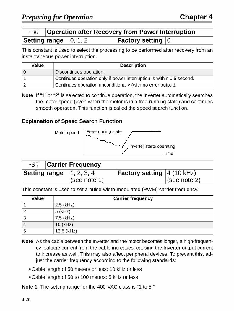
Value Description0 Discontinues operation.1 Continues operation only if power interruption is within 0.5 second.2 Continues operation unconditionally (with no error output).
Note If “1” or “2” is selected to continue operation, the Inverter automatically searchesthe motor speed (even when the motor is in a free-running state) and continuessmooth operation. This function is called the speed search function.
Explanation of Speed Search Function
Motor speed Free-running state
Inverter starts operating
Time
n37 Carrier FrequencySetting range 1, 2, 3, 4
(see note 1)Factory setting 4 (10 kHz)
(see note 2)
This constant is used to set a pulse-width-modulated (PWM) carrier frequency.
Value Carrier frequency1 2.5 (kHz)2 5 (kHz)3 7.5 (kHz)4 10 (kHz)5 12.5 (kHz)
Note As the cable between the Inverter and the motor becomes longer, a high-frequen-cy leakage current from the cable increases, causing the Inverter output currentto increase as well. This may also affect peripheral devices. To prevent this, ad-just the carrier frequency according to the following standards:
Cable length of 50 meters or less: 10 kHz or less
Cable length of 50 to 100 meters: 5 kHz or less
Note 1. The setting range for the 400-VAC class is “1 to 5.”
Preparing for Operation Chapter 4
4-21
Note 2. The factory setting for the 3G3EV-A4015-CUE is “3.”
Note 3. With the 400-VAC class, the continuous output current cannot be used to 100%of the rated value if the constant is set to “5” for Inverters of 0.75 kW or less or if itis set to “4” or “5” for an Inverter of 1.5 kW.Set the constant so that the continuous output current does not exceed the val-ues shown in the following tables.
400-VAC Inverters of 0.75 kW or Less
Carrier frequency set value Max. continuous output current1 to 4 Up to 100% of the rated output5 Up to 90% of the rated output
400-VAC Inverter of 1.5 kW
Carrier frequency set value Max. continuous output current1 to 3 Up to 100% of the rated output4 Up to 85% of the rated output5 Up to 75% of the rated output
Preparing for Operation Chapter 4
4-22
n39 Frequency Reference GainSetting range 0.10 to 2.55
(times)Factory setting 1.00 (times)
Unit of setting 0.01 (times)
n40 Frequency Reference BiasSetting range –99 to 99 (%) Factory setting 0 (%)Unit of setting 1 (%)
• These constants are used to set the relationship between analog voltage and refer-ence frequencies when frequency references are input through control terminals FRand FC.
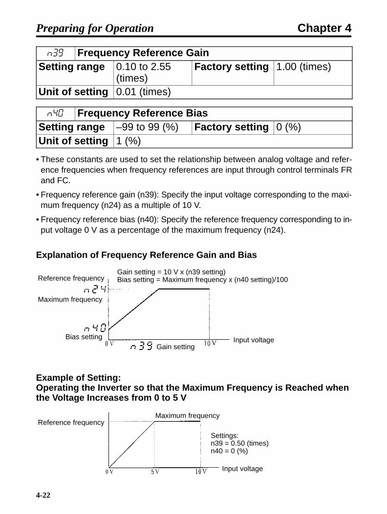
• Frequency reference gain (n39): Specify the input voltage corresponding to the maxi-mum frequency (n24) as a multiple of 10 V.
• Frequency reference bias (n40): Specify the reference frequency corresponding to in-put voltage 0 V as a percentage of the maximum frequency (n24).
Explanation of Frequency Reference Gain and Bias
Reference frequency
Maximum frequency
Bias setting
Gain setting = 10 V x (n39 setting)Bias setting = Maximum frequency x (n40 setting)/100
Gain settingInput voltage
Example of Setting:Operating the Inverter so that the Maximum Frequency is Reached whenthe Voltage Increases from 0 to 5 V
Reference frequencyMaximum frequency
Settings:n39 = 0.50 (times)n40 = 0 (%)
Input voltage
Preparing for Operation Chapter 4

4-23
n61 Stop Key SelectionSetting range 0, 1 Factory setting 0
• When inputting Inverter operation from the control terminals, the Stop Key on the Digi-tal Operator can be set to “enabled” or “disabled.”
Value Description0 Stop Key enabled1 Stop Key disabled
Note 1. When operating the Inverter from the Digital Operator, the Stop Key is alwaysenabled irrespective of its setting.
Note 2. This constant is available for models with a PROM number (software version)of “200” or higher.
n64 Operator’s Frequency Setting MethodSetting range 0, 1 Factory setting 0
• Used for setting the frequency from the Digital Operator.
• Select the Enter Key operation when setting the frequency command from the DigitalOperator.
Value Description0 Enter Key required for changing frequency1 Enter Key not required for changing frequency (may be changed using
Increment and Decrement Keys.)
n68 Error HistoryThis constant can only be displayed. It cannot be set.
• Information about the last error is recorded in this constant. Use this information fortroubleshooting purposes.
• The display format is as follows:
Error code
8.8.8.
Note This constant is available for models with a PROM number (software version) of“220” or higher.
Preparing for Operation Chapter 4

4-24
• Recorded are Inverter errors and other errors that actuate a protective mechanism.Warning (automatically recovered error) is not recorded.
• If no error has occurred, the indicator is not lit.
• All error codes are listed below.
Error code Description Error category %c Overcurrent (OC) Errors that actuate protective %U Main circuit overvoltage (OV) mechanism
uU1 Main circuit undervoltage (UV1)uU2 Control power supply fault (UV2) %h Radiation fin overheated (OH)%l1 Motor overload (OL1)%l2 Inverter overload (OL2)ef1 External fault (EF1)f00 Initial memory error Inverter errorsf01 ROM errorf04 Constant errorf05 A/D converter errorf06 Option error
Preparing for Operation Chapter 4

4-25
4-3 Test Run
After wiring is complete, perform a test run of the Inverter as follows. First,start the motor through the Digital Operator without connecting the motorto the mechanical system. Next, connect the motor to the mechanical sys-tem and perform a test run. Finally, operate the controller to make sure thatthe sequence of operations is correct.This section only describes how to perform a test run using the DigitalOperator.
4-3-1 Checking Wiring• Check that terminals R, S, and T receive power supply.200-VAC Class
Three-phase input: 200 to 230 VAC, 50/60 HzSingle-phase input: 200 to 240 VAC, 50/60 Hz (terminal R and S)(Single-phase input is only applicable to 3G3EV-AB.)
400-VAC ClassThree-phase input: 380 to 460 VAC, 50/60 Hz
• Check that terminals U, V, and W are correctly connected to the motor power cables.
• Do not connect the mechanical system to the motor. (The motor must be in no-loadstatus.)
• If signal lines are connected to control terminals, turn terminals SF and SR off.
4-3-2 Turning Power On and Checking Indicator Display• Check that the ALARM indicator is not lit.
• Check that the RUN indicator is flashing.
4-3-3 Initializing Constants n01
• Set “8” or “9” (3-wire sequence mode) in constant no. 01 to initialize constants.
4-3-4 Setting a V/f Pattern• Set the maximum frequency (“FMAX” or constant no. 24), maximum voltage (“VMAX”or constant no. 25), and maximum voltage frequency (“FBAS” or constant no. 26) ac-cording to the operating conditions.
Preparing for Operation Chapter 4

4-26
4-3-5 Setting Rated Motor Amperage• Set the rated motor amperage in constant no. 31 (electronic thermal reference current)or with the “THR” indicator lit.
4-3-6 Setting the Reference Frequency• Set the frequency corresponding to the motor speed in constant no. 11 (frequency ref-erence 1) or with the “FREF” indicator lit.
4-3-7 Operating the Inverter with the Digital Operator• Press the RUN Key to rotate the motor in the forward direction. (If the PRGM indicatoris lit in the constant item indicators section, press the Mode Key once to light the FREFindicator. If a red indicator in the stopped item indicators section is lit, the run commandcannot be accepted.)
• Check that the motor rotates smoothly without making noise.
• Check that the direction of rotation is correct.
4-3-8 Checking Output Frequency and Amperage
• Light the FOUT indicator (output frequency monitor) and make sure that the displayedvalue matches the reference frequency.
• Light the IOUT indicator (output current monitor) and check for overcurrent.
4-3-9 Checking Operation during Reverse Rotation• Rotate the motor in the reverse direction and check the same items as above.
4-3-10 Checking Operation with Mechanical SystemConnected
• Press the STOP/RESET Key to stop the motor.
• Connect the mechanical system to the motor and check the same items as above.
4-3-11 Checking Operation Performed by Controller• Light the MODE indicator and set the actual operation mode.
• Operate the Inverter with the controller, check for noise resulting from mechanical res-onance, and check that the sequence of operations is correct.
Preparing for Operation Chapter 4

Chapter 5
Operation
5-1 Protective and Diagnostic Functions
5-2 Troubleshooting
5-3 Maintenance and Inspection
5

5-2
5-1 Protective and Diagnostic Functions
The 3G3EV has excellent protective and diagnostic functions. The RUNand ALARM indicators on the front panel indicate the current Inverter sta-tus, and the data display section also displays information about an errorthat has occurred. These functions therefore enable the user to take theappropriate actions to correct most errors.
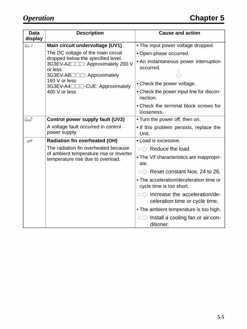
List of Error CodesInverter Indicator Data Descriptionstatus RUN ALARM display
p
Normal Flashes Not lit --- Ready to runLit Not lit --- Normal operation in progress
Warning Flashes Flashes ef Simultaneous input of forward and re-verse rotation commands
Lit Flashes uU Main circuit undervoltage (UV) %U Main circuit overvoltage (OV) %h Radiation fin overheated (OH)
Digital Operator stopped (STP)Protective Not lit Lit %c Overcurrent (OC)mecha-nism actu
%U Main circuit overvoltage (OV)nism actu-ated
uU1 Main circuit undervoltage (UV1)ated
uU2 Control power supply fault (UV2) %h Radiation fin overheated (OH)%l1 Motor overload (OL1)%l2 Inverter overload (OL2)ef1 External fault (EF1)
Inverter Not lit Lit f00 Initial memory errorerror f01 ROM error
f04 Constant errorf05 A/D converter errorf06 Option error
Not lit Not lit (Not lit) Control circuit error
Operation Chapter 5

5-3
Data Display and Action to be Taken when Warning StatusArises
The ALARM indicator flashes when warning status arises. The data display section alsoflashes.
When warning status arises, no error code is output.
Eliminating the cause recovers the system automatically.
Datadisplay
Description Action
ef
flashingSimultaneous input of forward andreverse rotation commandsForward and reverse rotationcommands were simultaneously inputfor 0.5 second or more. The Inverterdecelerates and stops the motor.
• Review the sequence.
uU
flashingMain circuit undervoltage (UV)The DC voltage of the main circuitdropped below the low-voltagedetection level when the Inverter wasstopped.
• Check the power voltage.
• Check the power input line for discon-nection.
• Check the terminal block screws forlooseness.
%U
flashingMain circuit overvoltage (OV)The DC voltage of the main circuitexceeded the overvoltage detectionlevel when the Inverter was stopped.
• Check the power voltage.
%h
flashingRadiation fin overheated (OH)The radiation fin overheated when theInverter was stopped.
• Check the ambient temperature.
• Install a cooling fan or air conditioner.
flashingDigital Operator stopped (STP)The STOP/RESET Key on the DigitalOperator was pressed while theInverter was being operated usingcontrol circuit terminals SF and SR.The Inverter decelerates and stopsthe motor.
• Open both SF and SR.
Operation Chapter 5

5-4
Data Display and Action to be Taken when ProtectiveMechanism is Actuated
The ALARM indicator lights up when the protective mechanism is actuated. In thisevent, Inverter output is shut off, and the motor coasts to a stop.
Check the cause of the error, take the necessary action, and perform fault reset or turnthe power off, then on.
Datadisplay
Description Cause and action
%c Overcurrent (OC)The Inverter output currentinstantaneously exceeded 250% of therated amperage.
• The output side of the Inverter isshorted or grounded.
• Load inertia is excessive.
• The acceleration and decelerationtime settings are too short.
• A special motor is used.
• The motor was started during freerunning.
• The magnetic contactor on the outputside of the Inverter was opened andclosed.
• Determine the cause of the error, takethe necessary action, and reset thesystem.
%U Main circuit overvoltage (OV)Because regenerative energy from themotor was excessive, the DC voltageof the main circuit exceededapproximately 410 V. (400-VAC Class, 820 V)
• The deceleration time setting is tooshort.
• Increase the deceleration time.
• Connect a braking resistor (or brakingresistor unit).
• The regenerative energy becomesexcessive when returning from theovershoot during acceleration.
• Connect a braking resistor (or brakingresistor unit).
Operation Chapter 5
5-5
Datadisplay
Cause and actionDescription
uU1 Main circuit undervoltage (UV1)The DC voltage of the main circuitdropped below the specified level.3G3EV-A2: Approximately 200 Vor less3G3EV-AB: Approximately160 V or less3G3EV-A4-CUE: Approximately400 V or less
• The input power voltage dropped.
• Open-phase occurred.
• An instantaneous power interruptionoccurred.
• Check the power voltage.
• Check the power input line for discon-nection.
• Check the terminal block screws forlooseness.
uU2 Control power supply fault (UV2)A voltage fault occurred in controlpower supply.
• Turn the power off, then on.
• If this problem persists, replace theUnit.
%h Radiation fin overheated (OH)The radiation fin overheated becauseof ambient temperature rise or Invertertemperature rise due to overload.
• Load is excessive.
Reduce the load.
• The V/f characteristics are inappropri-ate.
Reset constant Nos. 24 to 26.
• The acceleration/deceleration time orcycle time is too short.
Increase the acceleration/de-celeration time or cycle time.
• The ambient temperature is too high.
Install a cooling fan or air con-ditioner.
Operation Chapter 5
5-6
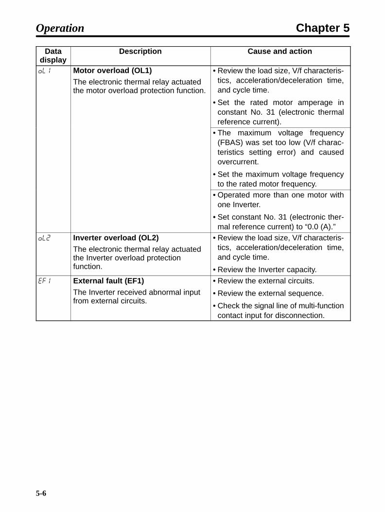
Datadisplay
Cause and actionDescription
%l1 Motor overload (OL1)The electronic thermal relay actuatedthe motor overload protection function.
• Review the load size, V/f characteris-tics, acceleration/deceleration time,and cycle time.
• Set the rated motor amperage inconstant No. 31 (electronic thermalreference current).
• The maximum voltage frequency(FBAS) was set too low (V/f charac-teristics setting error) and causedovercurrent.
• Set the maximum voltage frequencyto the rated motor frequency.
• Operated more than one motor withone Inverter.
• Set constant No. 31 (electronic ther-mal reference current) to “0.0 (A).”
%l2 Inverter overload (OL2)The electronic thermal relay actuatedthe Inverter overload protectionfunction.
• Review the load size, V/f characteris-tics, acceleration/deceleration time,and cycle time.
• Review the Inverter capacity.
ef1 External fault (EF1)The Inverter received abnormal inputfrom external circuits.
• Review the external circuits.
• Review the external sequence.
• Check the signal line of multi-functioncontact input for disconnection.
Operation Chapter 5
5-7
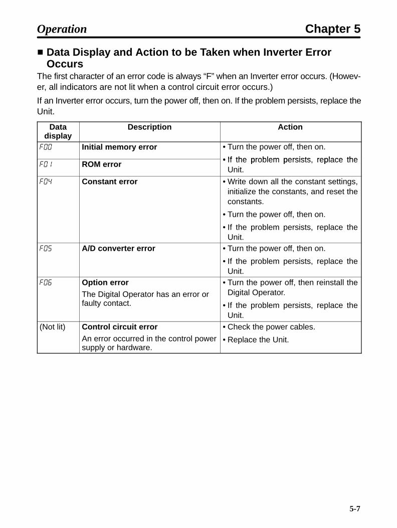
Data Display and Action to be Taken when Inverter ErrorOccurs
The first character of an error code is always “F” when an Inverter error occurs. (Howev-er, all indicators are not lit when a control circuit error occurs.)
If an Inverter error occurs, turn the power off, then on. If the problem persists, replace theUnit.
Datadisplay
Description Action
f00 Initial memory error • Turn the power off, then on.
• If the problem persists replace thef01 ROM error • If the problem persists, replace the
Unit.
f04 Constant error • Write down all the constant settings,initialize the constants, and reset theconstants.
• Turn the power off, then on.
• If the problem persists, replace theUnit.
f05 A/D converter error • Turn the power off, then on.
• If the problem persists, replace theUnit.
f06 Option errorThe Digital Operator has an error orfaulty contact.
• Turn the power off, then reinstall theDigital Operator.
• If the problem persists, replace theUnit.
(Not lit) Control circuit errorAn error occurred in the control powersupply or hardware.
• Check the power cables.
• Replace the Unit.
Operation Chapter 5

5-8
5-2 Troubleshooting
If the Inverter or motor does not operate properly when the system isstarted, constant settings or wiring may be incorrect. In this case, take theappropriate action as described below. (If an error code is displayed, referto 5-1 Protective and Diagnostic Functions.)
5-2-1 Constants Fail to Set
err is Displayed in the Data Display Section.• If an attempt is made to set a value outside the allowable range, err is displayed in thedata display section. The value is canceled and the data display section re-displaysthe original value. For example, this error occurs when:
An attempt is made to set a reference frequency value higher than the maximumfrequency value.
An attempt is made to set a maximum voltage frequency (basic frequency) valuehigher than the maximum frequency value.
Check the setting range, then set the constant correctly.
The Display Does Not Change when the Increment orDecrement Key is Pressed.
• Value “0” is set in n01 (constant write-inhibit selection)
Set “1” in n01.
• The Digital Operator is not connected properly.
Turn the power off. After all indicators on the front panel go off, remove the DigitalOperator, then reinstall it.
5-2-2 Motor Fails to Operate
The Motor Does Not Operate when the RUN Key on the DigitalOperator is Pressed.
• Operation mode was not selected correctly.
If “1,” “3,” or “5” is set in n02, the motor does not operate when the RUN Key on theDigital Operator is pressed.
Always set “0,” “2,” or “4” in n02.
Operation Chapter 5

5-9
• The reference frequency is too low.
When the reference frequency is less than 1.5 Hz, the Inverter cannot operate.Change the reference frequency to 1.5 Hz or more.
• The sequence input method is wrong.
If the 3-wire sequence input mode is selected as an external terminal function insteadof the actual 2-wire sequence input mode, the motor will not run, in which case changethe constant or change to the sequence input that matches the constant setting.
The Motor Does Not Operate when an External Run Signal isInput.
• Operation mode is selected incorrectly.
If “0,” “2,” or “4” is set in n02, the motor does not operate when a run signal is input.
Always set “1,” “3,” or “5” in n02.
• The reference frequency is too low.
When the reference frequency is less than 1.5 Hz, the Inverter does not operate.Change the reference frequency to 1.5 Hz or more.
The Motor Stops during Acceleration or when a Load isConnected.
• Load is too high.
The 3G3EV has a stall prevention function and full automatic torque boost function.However, if acceleration or load is too high, the motor response limit will be exceeded.
To prevent this, increase acceleration time or reduce load. Motor capacity should bealso increased.
5-2-3 Motor Rotates in the Wrong Direction• The motor output line is connected incorrectly.
If terminals U, V, and W on the Inverter are correctly connected to terminals U, V, and Won the motor, the motor rotates in the forward direction when a forward rotation com-mand is input. Since the forward direction of rotation depends on the motor manufac-turer and model, check the motor specifications.
Operation Chapter 5

5-10
To reverse the direction of rotation, switch the wires of two phases of U, V, and W asshown below.
Inverter Motor
Forward rotation
Reverse rotation
5-2-4 Motor Deceleration is Too Slow
Deceleration Time is Too Long Even if a Braking Resistor isConnected.
• Value 0 (stall prevention during deceleration) is set in n33.
When a braking resistor is connected, always set “1” (no stall prevention during decel-eration) in n33. If “0” is set, the braking resistor will not be used.
• The deceleration time set in n21 is too long.
Check the deceleration time setting.
• Motor torque is insufficient.
If the constant settings are normal and overvoltage does not occur, motor capacity isinsufficient.
Motor capacity should be increased.
5-2-5 Vertical-axis Load Drops when Brakes areApplied
• Sequence is incorrect.
The Inverter remains in DC braking status (50% of the n31 setting) for 0.5 second afterdeceleration is complete. Modify the sequence so that brakes are applied when theInverter enters DC braking status.
• Brakes are inappropriate.
Always use control brakes, not holding brakes.
Operation Chapter 5

5-11
5-2-6 Motor Burns• The dielectric strength of the motor is insufficient.
Surge arises when the motor (inductive load) is connected to the output side of theInverter. Normally, the maximum surge voltage is approximately three times the powervoltage. Therefore, the dielectric strength of the motor to be used must be higher thanthe maximum surge voltage.
It is recommended that motors specifically for Inverters be used, especially for the400-VAC-class Inverters.
5-2-7 Controller Receives Noise when Inverter isStarted
• Noise derives from Inverter switching.
Take the following actions to prevent noise:
Reduce the carrier frequency of the Inverter.
The number of internal switching times is reduced, so noise can be reduced tosome extent.
Improve the frame ground.
A current generated by internal switching normally leaks into the frame ground.Therefore, connect the ground terminal with a sufficiently thick and short wire of 100
Ω or less.
Install an input noise filter.
Install an input noise filter (3G3IV-PHF) on the power input side of the Inverter.
Install an output noise filter.
Install an output noise filter (3G3IV-PLF) on the output side of the Inverter.
Provide a separate power supply for the sensor.
If the sensor malfunctions, provide a dedicated power supply for the sensor andinstall a noise filter on the power supply. For the signal line, use a shielded cable.
5-2-8 AM Radio Receives Noise when Inverter isStarted
• Noise derives from Inverter switching.
Take the following actions to prevent noise:
Reduce the carrier frequency of the Inverter.
The number of internal switching times is reduced, so noise can be reduced tosome extent.
Operation Chapter 5

5-12
Install an input noise filter.
Install an input noise filter (3G3IV-PHF) on the power input side of the Inverter.
Install an output noise filter.
Install an output noise filter (3G3IV-PLF) on the output side of the Inverter.
Use metal box and piping.
Metal can block off radio waves. Therefore, enclose the Inverter with a metal(steel) box to prevent radio waves from being emitted from the Inverter.
5-2-9 Ground Fault Interrupter is Actuated whenInverter is Started
• Leakage current flows through the Inverter.
Because switching is performed inside the Inverter, a leakage current flows throughthe Inverter. This leakage current may actuate the ground fault interrupter, shutting thepower off.
Use a ground fault interrupter with a high leakage-current detection value (sensitivityamperage of 200 mA or more, operating time of 0.1 second or more) or the one withhigh-frequency countermeasures (for Inverter).
Reducing the carrier frequency value is also relatively effective.
Note also that a leakage current increases in proportion to the cable length. Normally,an approximately 5 mA leakage current is generated per meter (cable length).
5-2-10 Mechanical System Makes Noise• The carrier frequency and the natural frequency of the mechanical system resonates.
Take the following actions:
Adjust the carrier frequency.
Adjusting the carrier frequency (n37) may prevent resonance from occurring.
Install vibration-proof rubber.
Install vibration-proof rubber on the motor base.
5-2-11 Motor Does Not Operate with EF Warning• EF Warning (simultaneous input of forward and reverse commands) is a warningalarm that is issued when forward and reverse commands are simultaneously input forlonger than 500 ms. Check the Inverter’s sequence input.
• The Inverter input may be set to the ON state due to the current leaked in from the con-trol output.
Operation Chapter 5
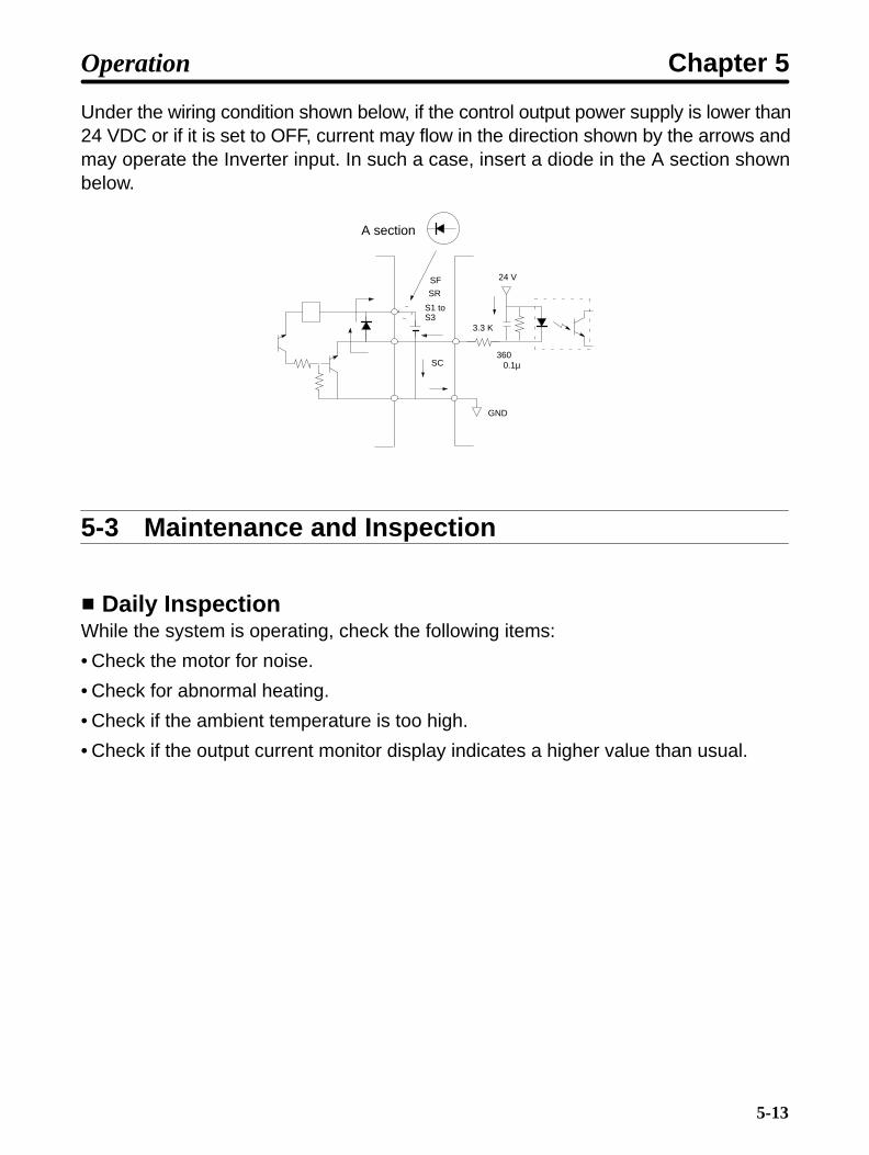
5-13
Under the wiring condition shown below, if the control output power supply is lower than24 VDC or if it is set to OFF, current may flow in the direction shown by the arrows andmay operate the Inverter input. In such a case, insert a diode in the A section shownbelow.
A section
SF
SR
S1 toS3
24 V
3600.1µ
GND
SC
3.3 K
5-3 Maintenance and Inspection
Daily InspectionWhile the system is operating, check the following items:
• Check the motor for noise.
• Check for abnormal heating.
• Check if the ambient temperature is too high.
• Check if the output current monitor display indicates a higher value than usual.
Operation Chapter 5

5-14
Regular MaintenanceCheck the items below during regular maintenance.
Before starting inspection, always turn the power off, then wait at least one minute afterall indicators on the front panel go off. Touching terminals immediately after turning thepower off may cause an electrical shock.
• Check the terminal block screws for looseness.
• Check if electrically conductive dust or oil mist adheres to the terminal block.
• Check the Inverter set screws for looseness.
• Check if dust or dirt builds up on the heat sink (aluminum portion on the rear of theUnit).
• Check if dust builds up in the air vents.
• Check if the appearance is normal.
• Check if the cooling fan for the control panel operates normally. (Check for noise orabnormal vibration, and also check if the total hours of operation has exceeded thevalue shown in the specifications.)
Regular Parts MaintenanceAn Inverter consists of many different parts. It can provide its full performance only whenthese parts operate normally. Some electronic parts require maintenance depending onthe service conditions. To allow the Inverter to operate normally over an extended peri-od of time, always perform regular inspection and parts replacement according to theservice life of each part.
Regular inspection intervals vary according to the Inverter installation environment andservice conditions.
The maintenance interval for this Inverter is shown below. Use this information as aguide to regular maintenance.
The standard interval for regular maintenance is as follows:
Electrolytic capacitor: Approximately 5 years (8 hours of operation per day)
As for service conditions, it is assumed that the ambient temperature of the Inverteris 40°C, and the Inverter is used under rated operating conditions (rated torque) andis installed as specified in the User’s Manual.
To extend maintenance intervals, ambient temperatures should be lowered, and power-on time should be minimized.
Note For the maintenance method, contact your nearest local sales representative.
Operation Chapter 5

Chapter 6
Specifications
6-1 Specifications of Main Unit
6

6-2
6-1 Specifications of Main Unit
RatingThree Model 3G3EV- A2001(-) A2002(-) A2004(-) A2007(-) A2015(-)phase,200 VAC
Powersupply
Rated voltageand frequency
Three-phase, 200 to 230 VAC, 50/60 Hzpp y
Allowablevoltagefluctuation
–15% to 10 %
Allowablefrequencyfluctuation
±5%
Heating value (W) 11.9 18.8 33.2 51.7 71.6Weight (kg) 0.5 0.6 0.9 1.3 1.5
Single/
Model 3G3EV- AB001(-) AB002(-) AB004(-) AB007(-) AB015(-)gphase/Threephase
Powersupply
Rated voltageand frequency
Single-phase, 200 to 240 VAC, 50/60 HzThree-phase, 200 to 230 VAC, 50/60 Hz
phase,200 VAC
pp yAllowablevoltagefluctuation
–15% to 10 %
Allowablefrequencyfluctuation
±5%
Heating value (W) 12.6 20.3 25.3 55.3 78.4Weight (kg) 0.5 0.6 1.3 1.3 2.0
Maximum applicable motorcapacity (kW)
0.1 0.2 0.4 0.75 1.5
Outputspecifi-
Rated output capacity(kVA)
0.3 0.6 1.1 1.9 2.7p
cations Rated output current (A) 0.8 1.5 3.0 5.0 7.0Rated output voltage Three-phase, 200 to 230 VAC
(Corresponds to the input voltage)Maximum outputfrequency
400 Hz (Parameter setting)
Cooling method Self-cooling
Specifications Chapter 6

6-3
Threeh
Model 3G3EV- --- A4002(-) A4004(-) A4007(-) A4015(-)phase,400 VAC
Powersupply
Rated voltageand frequency
Three-phase, 380 to 460 VAC, 50/60 Hzpp y
Allowablevoltagefluctuation
–15% to 10 %
Allowablefrequencyfluctuation
±5%
Heating value (W) --- 25.5 34.7 56.0 78.5Weight (kg) --- 1.0 1.0 1.5 2.0
Maximum applicable motor capacity(kW)
--- 0.2 (0.37) 0.4 (0.55) 0.75 (1.1) 1.5 (1.5)
Outputspecifi-
Rated output capacity(kVA)
--- 0.9 1.4 2.6 3.7p
cations Rated output current (A) --- 1.2 1.8 3.4 4.8Rated output voltage Three-phase, 380 to 460 VAC
(Corresponds to the input voltage)Maximum outputfrequency
400 Hz (Parameter setting)
Cooling method Self-cooling
General SpecificationsInstallation type Panel mountingInstallation site Indoor (free from corrosive gases and dust)Ambient temperature foroperation
–10° to 50°C
Humidity 90% or less (no-condensing)Ambient temperature for storage –20° to 60°CAltitude 1,000 m max.Vibration resistance Less than 20 Hz: 1G 9.8 m/s2 or less
20 to 50 Hz: 0.2G 1.96 m/s2 or lessCable length between Inverterand motor
100 m max.
Specifications Chapter 6

6-4
Control CharacteristicsControl method Sine-wave PWM method (automatic torque boost)Frequency controlrange
1.5 to 400 Hz
Frequency accuracy(temperaturefluctuation)
Digital command:±0.01% (–10°C to 50°C)Analog command:±1% (25 ±10°C)
Frequency settingresolution
Digital command:0.1 Hz (less than 100 Hz), 1 Hz (100 Hz or more)Analog command:0.06 Hz (60 Hz)
Frequency outputresolution
0.1 Hz (operation resolution)
Overload resistance 1 minute or less when 150% of rated output current is receivedFrequency settingsignal
0 to 10 VDC (20 kΩ) or 4 to 20 mA (250 Ω)Note This setting can be switched using the internal DIP switch.
Acceleration/Deceleration time
0.0 to 999 seconds (acceleration and deceleration times areset separately)
Braking torque(continuousregenerative braking)
Approximately 20%Note 125% to 220% when braking resistor is externally
installed.Voltage/Frequencycharacteristics
Simple V/f pattern setting
Specifications Chapter 6
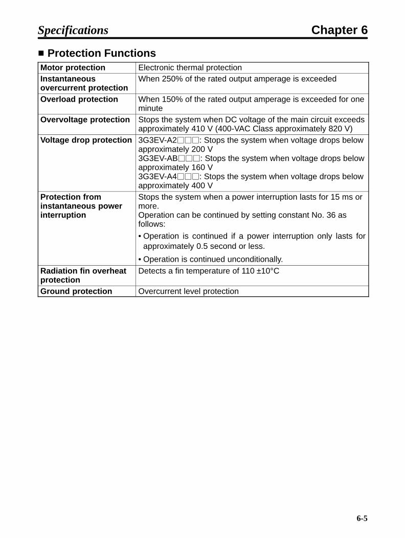
6-5
Protection FunctionsMotor protection Electronic thermal protectionInstantaneousovercurrent protection
When 250% of the rated output amperage is exceeded
Overload protection When 150% of the rated output amperage is exceeded for oneminute
Overvoltage protection Stops the system when DC voltage of the main circuit exceedsapproximately 410 V (400-VAC Class approximately 820 V)
Voltage drop protection 3G3EV-A2: Stops the system when voltage drops belowapproximately 200 V3G3EV-AB: Stops the system when voltage drops belowapproximately 160 V3G3EV-A4: Stops the system when voltage drops belowapproximately 400 V
Protection frominstantaneous powerinterruption
Stops the system when a power interruption lasts for 15 ms ormore.Operation can be continued by setting constant No. 36 asfollows:
• Operation is continued if a power interruption only lasts forapproximately 0.5 second or less.
• Operation is continued unconditionally.Radiation fin overheatprotection
Detects a fin temperature of 110 ±10°C
Ground protection Overcurrent level protection
Specifications Chapter 6

6-6
Operation SpecificationsControl input Three photocoupler input terminals (24 VDC, 8 mA)
• Forward/stop [SF]
• Reverse/stop [SR]
• Multi-function input [S1] (set in constant No. 06)Select either of “fault reset,” “external fault,” and “multi-stepspeed command.”
Note When 3-wire sequence mode (constant No. 01 = “9”) is se-lected, the terminals become as follows:
• Run command [SF]
• Stop command [SR]
• Forward/reverse rotation command [S1]
One analog input terminal (0 to 10 VDC or 4 to 20 mA)
• Frequency reference input [Between FC and FR]Control output One SPDT relay contact output terminal [MA, MB]
(30 VDC and 1A; 250 VAC and 1A)
• Multi-function contact output (set in constant No. 09)Select either of “fault occurrence,” “operation in progress,” and“frequency matching.”
Specifications Chapter 6

Chapter 7
Appendix A
7-1 Notes on Using Inverter for Motor
7-2 Frequency Reference by Amperage Input
7-3 List of Product Models
7

7-2
7-1 Notes on Using Inverter for Motor
Using Inverter for Existing Standard MotorWhen a standard motor is operated with this Inverter, a power loss is slightly higher thanwhen operated with a commercial power supply.
In addition, cooling effects also decline in the low-speed range, resulting in an increasein the motor temperature. Therefore, motor torque should be reduced in the low speedrange.
The figure on the right-hand side shows allowable load characteristics of a standardmotor.
If 100% torque is continuously required in the low-speed range, use a special motor foruse with Inverters.
Allowable Load Characteristics of Standard Motor
25% ED (or 15 minutes)40% ED (or 20 minutes)
60% ED (or 40 minutes)
Continuous
Frequency (Hz)
Torq
ue (
%)
High-speed OperationWhen using the motor at a high speed (60 Hz or more), note that problems may arise indynamic balance, bearing durability, and so on.
Torque CharacteristicsWhen the motor is operated with the Inverter, torque characteristics differ from whenoperated with a commercial power supply. Check the load torque characteristics of themachine to be used with the motor.
Appendix A Chapter 7

7-3
VibrationThe 3G3EV series employs high carrier PWM control to reduce motor vibration. Whenthe motor is operated with this Inverter, motor vibration is almost the same as when op-erated with a commercial power supply.
However, motor vibration may become greater in the following cases:
• Resonance with the natural frequency of mechanical system
Take special care when a machine that has been operated at a constant speed is tobe operated in variable speed mode. If resonance occurs, install vibration-proof rub-ber on the motor base.
• Imbalanced rotor
Take special care when the motor is operated at a high speed (60 Hz or more).
NoiseNoise is almost the same as when the motor is operated with a commercial power sup-ply. However, motor noise becomes louder when the motor is operated at a speed high-er than the rated speed (60 Hz).
Using Inverter for Special Motors
Pole-changing MotorThe rated amperage of pole-changing motors differs from that of standard motors.Select, therefore, an appropriate Inverter according to the maximum amperage of themotor to be used. Before changing the number of poles, always make sure that the mo-tor has stopped. Otherwise, the overvoltage protection or overcurrent protection mech-anism will be actuated, resulting in an error.
Submersible MotorThe rated amperage of submersible motors is higher than that of standard motors.Therefore, always select an Inverter by checking its rated amperage. When the dis-tance between the motor and the Inverter is long, use a cable thick enough to preventmotor torque reduction.
Explosion-proof MotorWhen an explosion-proof motor or increased safety type motor is to be used, it must besubject to an explosion-proof test in conjunction with the Inverter. This is also applicablewhen an existing explosion-proof motor is to be operated with the Inverter. However,since the Inverter itself is not explosion-proof, always install it in a safe place.
Appendix A Chapter 7

7-4
GearmotorThe speed range for continuous operation differs according to the lubrication methodand motor manufacturer. In particular, continuous operation of an oil-lubricated motor inthe low speed range may result in burning. If the motor is to be operated at a speed high-er than 60 Hz, consult with the manufacturer.
Synchronous MotorThis motor is not suitable for Inverter control. If a group of synchronous motors is individ-ually turned on and off, synchronism may be lost.
Single-phase MotorThis motor is not suitable for Inverter control. It should be replaced with a three-phasemotor.
Power Transmission Mechanism (Speed Reducers, Belts,Chains, and so on)
If an oil-lubricated gearbox or speed reducer is used in the power transmission mecha-nism, note that oil lubrication will be affected when the motor operates only in the lowspeed range. Note also that the power transmission mechanism will make noise andexperience problems with service life and durability if the motor is operated at a speedhigher than 60 Hz.
7-2 Frequency Reference by Amperage Input
Frequency references can be input in terms of amperage (4 to 20 mA) bychanging the setting of the DIP switch inside the Inverter.
Using the DIP Switch1. Changing constant settings
Before using the DIP switch, always set “4” or “5” in constant no. 02 (operation modeselection).
Note n02 = 4: Run commands are input through the Digital Operator, and frequencyreferences are input through control terminals.n02 = 5: Both run commands and frequency references are input through controlterminals.
2. Turning power off
Turn the power off, wait at least one minute after all indicators on the front panel gooff, then perform the following tasks.
Appendix A Chapter 7

7-5
3. Removing the Digital Operator
Insert a finger in the recessed section below the Digital Operator, then lift the under-neath of the Digital Operator.
When the connector comes off, grip the lower edges of the Digital Operator, andslide it down until it comes off.
4. Checking the DIP switch setting
The DIP switch is located in the lower part of the recessed section from which theDigital Operator was removed.
Appendix A Chapter 7
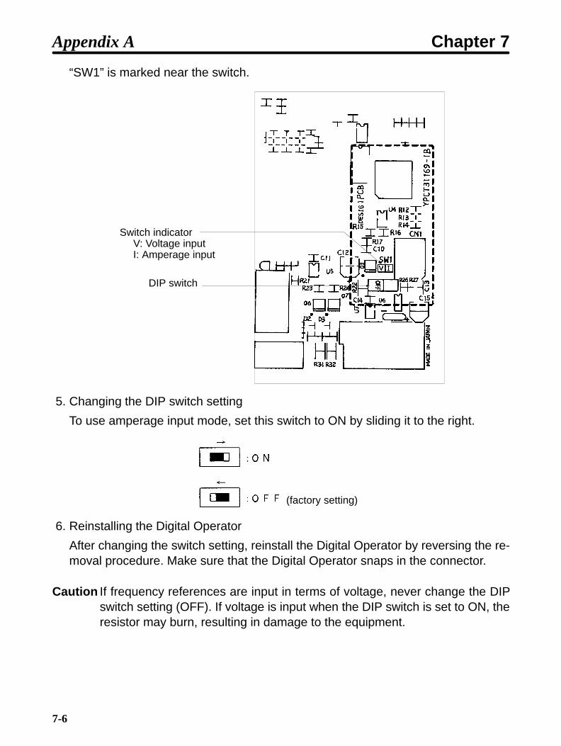
7-6
“SW1” is marked near the switch.
Switch indicatorV: Voltage inputI: Amperage input
DIP switch
5. Changing the DIP switch setting
To use amperage input mode, set this switch to ON by sliding it to the right.
(factory setting)
6. Reinstalling the Digital Operator
After changing the switch setting, reinstall the Digital Operator by reversing the re-moval procedure. Make sure that the Digital Operator snaps in the connector.
Caution If frequency references are input in terms of voltage, never change the DIPswitch setting (OFF). If voltage is input when the DIP switch is set to ON, theresistor may burn, resulting in damage to the equipment.
Appendix A Chapter 7

7-7
7-3 List of Product Models
InverterSpecifications Model
Standardmodels
Three-phase 200 VAC input 0.1 kW0.2 kW0.4 kW0.75 kW1.5 kW
3G3EV-A2001(-)3G3EV-A2002(-)3G3EV-A2004(-)3G3EV-A2007(-)3G3EV-A2015(-)
Single/Three-phase 200 VAC input 0.1 kW0.2 kW0.4 kW0.75 kW1.5 kW
3G3EV-AB001(-)3G3EV-AB002(-)3G3EV-AB004(-)3G3EV-AB007(-)3G3EV-AB015(-)
Three-phase 400 VAC input 0.2 kW0.4 kW0.75 kW1.5 kW
3G3EV-A4002(-)3G3EV-A4004(-)3G3EV-A4007(-)3G3EV-A4015(-)
Multi-functionmodels
Three-phase 200 VAC input 0.1 kW0.2 kW0.4 kW0.75 kW1.5 kW
3G3EV-A2001M(-)3G3EV-A2002M(-)3G3EV-A2004M(-)3G3EV-A2007M(-)3G3EV-A2015M(-)
Single/Three-phase 200 VAC input 0.1 kW0.2 kW0.4 kW0.75 kW1.5 kW
3G3EV-AB001M(-)3G3EV-AB002M(-)3G3EV-AB004M(-)3G3EV-AB007M(-)3G3EV-AB015M(-)
Three-phase 400 VAC input 0.2 kW0.4 kW0.75 kW1.5 kW
3G3EV-A4002M(-)3G3EV-A4004M(-)3G3EV-A4007M(-)3G3EV-A4015M(-)
SYSMAC BUSmodels
Three-phase 200 VAC input 0.1 kW0.2 kW0.4 kW0.75 kW1.5 kW
3G3EV-A2001R(-)3G3EV-A2002R(-)3G3EV-A2004R(-)3G3EV-A2007R(-)3G3EV-A2015R(-)
Single/Three-phase 200 VAC input 0.1 kW0.2 kW0.4 kW0.75 kW
3G3EV-AB001R(-)3G3EV-AB002R(-)3G3EV-AB004R(-)3G3EV-AB007R(-)
Appendix A Chapter 7

7-8
Braking Resistor (Duty Cycle 3% ED)Specifications Model
200-VAC class 0.1 kW/0.2 kW 400 Ω 3G3IV-PERF150WJ4010.4 kW/0.75 kW 200 Ω 3G3IV-PERF150WJ2011.5 kW 100 Ω 3G3IV-PERF150WJ101
400-VAC class 0.75 kW or less 750 Ω 3G3IV-PERF150WJ7511.5 kW 400 Ω 3G3IV-PERF150WJ401
Braking Resistor Unit (Duty Cycle 10% ED)Specifications Model
200-VAC class 0.4kW/0.75 kW 200 Ω, 70 W 3G3IV-PLKEB20P71.5 kW 100 Ω, 260 W 3G3IV-PLKEB21P5
400-VAC class 0.75 kW or less 750 Ω, 70 W 3G3IV-PLKEB40P71.5 kW 400 Ω, 260 W 3G3IV-PLKEB41P5
AC Reactor (for Three-Phase)Specifications Model
0.1 to 0.4 kW 2.5 A 4.2 mH 3G3IV-PUZBAB2.5A4.2MH0.75 kW 5 A 2.1 mH 3G3IV-PUZBAB5A2.1MH1.5 kW 10 A 1.1 mH 3G3IV-PUZBAB10A1.1MH
Input Noise Filter (for Three-Phase)Specifications Model
0.1 to 0.4 kW 5 A 3G3IV-PHF3005AZ0.75 kW 10A 3G3IV-PHF3010AZ1.5 kW 15 A 3G3IV-PHF3015AZ
Output Noise FilterSpecifications Model
0.1 to 1.5 kW 10 A 3G3IV-PLF310KA
Variable Resistor UnitSpecifications Model
3G3EV 2 k Ω 0.5 W 3G3EV-PETX3200
Appendix A Chapter 7

7-9
DIN TrackSpecifications Model
3G3EV-A2001(-) to 3G3EV-A2004(-)3G3EV-AB001(-) and 3G3EV-AB002(-)
3G3EV-PSPAT3
3G3EV-A2007(-) to 3G3EV-A2015(-)3G3EV-AB004(-) and 3G3EV-AB007(-)3G3EV-A4002(-) to 3G3EV-A4007(-)
3G3EV-PSPAT4
Appendix A Chapter 7

7-10
List of Constants Used with 3G3EV Standard Model
Constantno.
Indi-cators
Description Setting range Setting
n01 Constant 0: Only n01 can be set.write-inhibitselection
1: All constants can be set.selection/constant
8: Constant settings are initialized./constantinitialization 9: Inverter is initialized in 3-wire
sequence mode.n02 Mode operation
selectionRun command Frequency
reference0 Digital Operator Digital Operator1 Control terminal Digital Operator2 Digital Operator Control terminal
(voltage input)3 Control terminal Control terminal
(voltage input)4 Digital Operator Control terminal
(amperageinput)
5 Control terminal Control terminal(amperageinput)
n03 Stop mode 0: Deceleration stopselection 1: Free running
n04 Forward/Reverse
f%r: forward rotation/rotationselection
reU: reverse rotation
n06 Multi-function 0: Forward/reverse rotation commandinput selection 1: Fault reset
2: External fault (external fault when ON)3: External fault (external fault when
OFF)4: Multi-step speed command
n09 Multi-function 0: Fault occurrenceoutput selection 1: Operation in progress
2: Frequency matchingn11 Frequency
reference 10.0 to 400 (Hz) [6.0]
n12 Frequencyreference 2
0.0 to 400 (Hz) [0.0]
n20 Accelerationtime
0.0 to 999 (seconds) [10.0]
Appendix A Chapter 7

7-11
Constantno.
SettingSetting rangeDescriptionIndi-cators
n21 Decelerationtime
0.0 to 999 (seconds) [10.0]
n24 Maximumfrequency
50.0 to 400 (Hz) [60.0]
n25 Maximumvoltage
1 to 255 (V) (see note 1) [200]
n26 Maximumvoltagefrequency (basicfrequency)
1.6 to 400 (Hz) [60.0]
n31 Electronicthermalreferencecurrent
0.0 to 120% of rated Inverter amperageSpecify the rated motor amperage.
n33 Stall preventionduring
0: Stall preventionduringdeceleration 1: No stall prevention
n36 Operation after 0: Discontinues operation.recovery frompowerinterruption
1: Continues operation only if the powerinterruption is within 0.5 second.
interruption 2: Continues operation unconditionally.n37 Carrier 1: 2.5 (kHz) (see note 2)
frequency 2: 5 (kHz)3: 7.5 (kHz)4: 10 (kHz)
n39 Frequencyreference gain
0.10 to 2.00 (times) [1.00]
n40 Frequencyreference bias
–99 to 99 (%) [0]
n61 Stop Keyselection
0, 1 [0]
n64 Operator’sfrequencysetting method
0, 1 [0]
Note 1. The upper limit of setting range and the factory settings for the 400-VAC-classInverters are double the above values.
Note 2. The setting range of the 400-VAC-class Inverter is “1 to 5.” The factory setting ofthe 3G3EV-A4015M-CUE is “3.”
Note 3. Values in shaded sections or values in brackets represent factory settings.
Appendix A Chapter 7