Embed Size (px)
Citation preview
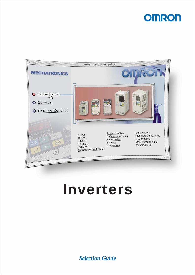
Selection Guide
Inverters
i
Table of contents
SYSDRIVE inverters Page
Inverter -- Outline 1. . . . . . . . . . . . . . . . . . . . . . . . . . . . . . . . . . . . . . . . . . . . . . . . . . . . . . . . . . . . . . . . . . . . . .
3G3EV 3. . . . . . . . . . . . . . . . . . . . . . . . . . . . . . . . . . . . . . . . . . . . . . . . . . . . . . . . . . . . . . . . . . . . . . . . . . . . . . . .System architecture 3. . . . . . . . . . . . . . . . . . . . . . . . . . . . . . . . . . . . . . . . . . . . . . . . . . . . . . . . . . . . . . . . . . . .Product overview 4. . . . . . . . . . . . . . . . . . . . . . . . . . . . . . . . . . . . . . . . . . . . . . . . . . . . . . . . . . . . . . . . . . . . . . .Accessories 4. . . . . . . . . . . . . . . . . . . . . . . . . . . . . . . . . . . . . . . . . . . . . . . . . . . . . . . . . . . . . . . . . . . . . . . . . . .Programming accessories 5. . . . . . . . . . . . . . . . . . . . . . . . . . . . . . . . . . . . . . . . . . . . . . . . . . . . . . . . . . . . . . .Technical data 5. . . . . . . . . . . . . . . . . . . . . . . . . . . . . . . . . . . . . . . . . . . . . . . . . . . . . . . . . . . . . . . . . . . . . . . . .Connections diagram 8. . . . . . . . . . . . . . . . . . . . . . . . . . . . . . . . . . . . . . . . . . . . . . . . . . . . . . . . . . . . . . . . . . .Technical documentation 10. . . . . . . . . . . . . . . . . . . . . . . . . . . . . . . . . . . . . . . . . . . . . . . . . . . . . . . . . . . . . . . .Dimensions 11. . . . . . . . . . . . . . . . . . . . . . . . . . . . . . . . . . . . . . . . . . . . . . . . . . . . . . . . . . . . . . . . . . . . . . . . . . . .
3G3JV 13. . . . . . . . . . . . . . . . . . . . . . . . . . . . . . . . . . . . . . . . . . . . . . . . . . . . . . . . . . . . . . . . . . . . . . . . . . . . . . . .System architecture 13. . . . . . . . . . . . . . . . . . . . . . . . . . . . . . . . . . . . . . . . . . . . . . . . . . . . . . . . . . . . . . . . . . . .Product overview 14. . . . . . . . . . . . . . . . . . . . . . . . . . . . . . . . . . . . . . . . . . . . . . . . . . . . . . . . . . . . . . . . . . . . . . .Accessories 14. . . . . . . . . . . . . . . . . . . . . . . . . . . . . . . . . . . . . . . . . . . . . . . . . . . . . . . . . . . . . . . . . . . . . . . . . . .Technical data 15. . . . . . . . . . . . . . . . . . . . . . . . . . . . . . . . . . . . . . . . . . . . . . . . . . . . . . . . . . . . . . . . . . . . . . . . .Connections diagram 17. . . . . . . . . . . . . . . . . . . . . . . . . . . . . . . . . . . . . . . . . . . . . . . . . . . . . . . . . . . . . . . . . . .Dimensions 18. . . . . . . . . . . . . . . . . . . . . . . . . . . . . . . . . . . . . . . . . . . . . . . . . . . . . . . . . . . . . . . . . . . . . . . . . . . .Set of parameters 19. . . . . . . . . . . . . . . . . . . . . . . . . . . . . . . . . . . . . . . . . . . . . . . . . . . . . . . . . . . . . . . . . . . . . .
3G3MV 23. . . . . . . . . . . . . . . . . . . . . . . . . . . . . . . . . . . . . . . . . . . . . . . . . . . . . . . . . . . . . . . . . . . . . . . . . . . . . . .System architecture 23. . . . . . . . . . . . . . . . . . . . . . . . . . . . . . . . . . . . . . . . . . . . . . . . . . . . . . . . . . . . . . . . . . . .Product overview 24. . . . . . . . . . . . . . . . . . . . . . . . . . . . . . . . . . . . . . . . . . . . . . . . . . . . . . . . . . . . . . . . . . . . . . .Accessories 25. . . . . . . . . . . . . . . . . . . . . . . . . . . . . . . . . . . . . . . . . . . . . . . . . . . . . . . . . . . . . . . . . . . . . . . . . . .Technical data 26. . . . . . . . . . . . . . . . . . . . . . . . . . . . . . . . . . . . . . . . . . . . . . . . . . . . . . . . . . . . . . . . . . . . . . . . .Connections diagram 28. . . . . . . . . . . . . . . . . . . . . . . . . . . . . . . . . . . . . . . . . . . . . . . . . . . . . . . . . . . . . . . . . . .Dimensions 29. . . . . . . . . . . . . . . . . . . . . . . . . . . . . . . . . . . . . . . . . . . . . . . . . . . . . . . . . . . . . . . . . . . . . . . . . . . .Set of parameters 31. . . . . . . . . . . . . . . . . . . . . . . . . . . . . . . . . . . . . . . . . . . . . . . . . . . . . . . . . . . . . . . . . . . . . .
3G3HV 41. . . . . . . . . . . . . . . . . . . . . . . . . . . . . . . . . . . . . . . . . . . . . . . . . . . . . . . . . . . . . . . . . . . . . . . . . . . . . . . .System architecture 41. . . . . . . . . . . . . . . . . . . . . . . . . . . . . . . . . . . . . . . . . . . . . . . . . . . . . . . . . . . . . . . . . . . .Product overview 42. . . . . . . . . . . . . . . . . . . . . . . . . . . . . . . . . . . . . . . . . . . . . . . . . . . . . . . . . . . . . . . . . . . . . . .Accessories 42. . . . . . . . . . . . . . . . . . . . . . . . . . . . . . . . . . . . . . . . . . . . . . . . . . . . . . . . . . . . . . . . . . . . . . . . . . .Programming accessories 44. . . . . . . . . . . . . . . . . . . . . . . . . . . . . . . . . . . . . . . . . . . . . . . . . . . . . . . . . . . . . . .Technical data 44. . . . . . . . . . . . . . . . . . . . . . . . . . . . . . . . . . . . . . . . . . . . . . . . . . . . . . . . . . . . . . . . . . . . . . . . .Connections diagram 45. . . . . . . . . . . . . . . . . . . . . . . . . . . . . . . . . . . . . . . . . . . . . . . . . . . . . . . . . . . . . . . . . . .Technical documentation 48. . . . . . . . . . . . . . . . . . . . . . . . . . . . . . . . . . . . . . . . . . . . . . . . . . . . . . . . . . . . . . . .Dimensions 49. . . . . . . . . . . . . . . . . . . . . . . . . . . . . . . . . . . . . . . . . . . . . . . . . . . . . . . . . . . . . . . . . . . . . . . . . . . .
3G3FV 51. . . . . . . . . . . . . . . . . . . . . . . . . . . . . . . . . . . . . . . . . . . . . . . . . . . . . . . . . . . . . . . . . . . . . . . . . . . . . . . .System architecture 51. . . . . . . . . . . . . . . . . . . . . . . . . . . . . . . . . . . . . . . . . . . . . . . . . . . . . . . . . . . . . . . . . . . .Product overview 52. . . . . . . . . . . . . . . . . . . . . . . . . . . . . . . . . . . . . . . . . . . . . . . . . . . . . . . . . . . . . . . . . . . . . . .Accessories 52. . . . . . . . . . . . . . . . . . . . . . . . . . . . . . . . . . . . . . . . . . . . . . . . . . . . . . . . . . . . . . . . . . . . . . . . . . .Programming accessories 54. . . . . . . . . . . . . . . . . . . . . . . . . . . . . . . . . . . . . . . . . . . . . . . . . . . . . . . . . . . . . . .Technical data 55. . . . . . . . . . . . . . . . . . . . . . . . . . . . . . . . . . . . . . . . . . . . . . . . . . . . . . . . . . . . . . . . . . . . . . . . .Connections diagram 56. . . . . . . . . . . . . . . . . . . . . . . . . . . . . . . . . . . . . . . . . . . . . . . . . . . . . . . . . . . . . . . . . . .Technical documentation 58. . . . . . . . . . . . . . . . . . . . . . . . . . . . . . . . . . . . . . . . . . . . . . . . . . . . . . . . . . . . . . . .Dimensions 58. . . . . . . . . . . . . . . . . . . . . . . . . . . . . . . . . . . . . . . . . . . . . . . . . . . . . . . . . . . . . . . . . . . . . . . . . . . .

ii
3G3JV
3G3MV
Functionality
3G3HV 3G3FV
Pow
er
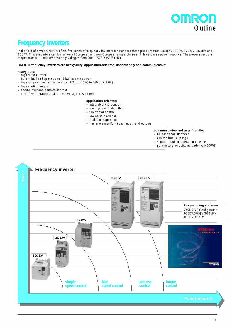
Frequency inverter
Programming softwareSYSDRIVE Configurator3G3EV/3G3JV/3G3MV/3G3HV/3G3FV
simplespeed control
fastspeed control
processcontrol
torquecontrol
3G3EV
1
Frequency invertersIn the field of drives OMRON offers five series of frequency inverters for standard three-phase motors: 3G3EV, 3G3JV, 3G3MV, 3G3HV and3G3FV. These inverters can be run on all European and non-European single-phase and three-phase power supplies. The power spectrumranges from 0.1...300 kW at supply voltages from 200 ... 575 V (50/60 Hz).
OMRON frequency inverters are heavy-duty, application-oriented, user-friendly and communicative:
heavy-duty:-- high rated current-- built-in brake chopper up to 15 kW inverter power-- high range of nominal voltage, i.e. 380 V (--10%) to 460 V (+ 15%)-- high starting torque-- short-circuit and earth-fault proof-- error-free operation at short-time voltage breakdown
application-oriented:-- integrated PID control-- energy-saving algorithm-- flux vector control-- low-noise operation-- brake management-- numerous multifunctional inputs and outputs
communicative and user-friendly:-- built-in serial interfaces-- diverse bus couplings-- standard built-in operating console-- parameterising software under WINDOWS
Outline
2
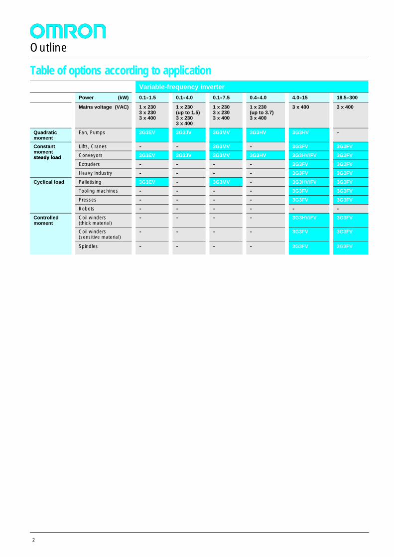
Table of options according to applicationVariable-frequency inverter
Power (kW) 0.1--1.5 0.1--4.0 0.1--7.5 0.4--4.0 4.0--15 18.5--300
Mains voltage (VAC) 1 x 2303 x 2303 x 400
1 x 230(up to 1.5)3 x 2303 x 400
1 x 2303 x 2303 x 400
1 x 230(up to 3.7)3 x 400
3 x 400 3 x 400
Quadraticmoment
Fan, Pumps 3G3EV 3G3JV 3G3MV 3G3HV 3G3HV --
Constantmoment
Lifts, Cranes -- -- 3G3MV -- 3G3FV 3G3FVConstantmomentsteady load Conveyors 3G3EV 3G3JV 3G3MV 3G3HV 3G3HV/FV 3G3FVsteady load
Extruders -- -- -- -- 3G3FV 3G3FV
Heavy industry -- -- -- -- 3G3FV 3G3FV
Cyclical load Palletising 3G3EV -- 3G3MV -- 3G3HV/FV 3G3FVCyclical load
Tooling machines -- -- -- -- 3G3FV 3G3FV
Presses -- -- -- -- 3G3FV 3G3FV
Robots -- -- -- -- -- --
Controlledmoment
Coil winders(thick material)
-- -- -- -- 3G3HV/FV 3G3FVmoment
Coil winders(sensitive material)
-- -- -- -- 3G3FV 3G3FV
Spindles -- -- -- -- 3G3FV 3G3FV
Outline
3G3EV inverter
3
General
The 3G3EV is a miniature variable-frequency inverter of great reliabili-ty due to a very high current-carrying capacity. The continuous outputcurrent of the 3G3EV is about 20% above the rated current of afour-pole standard motor.Advantages are a high starting torque even when fully loaded and notbeing susceptible to overload or shock loads. This increases theoperating time of your machine. Inputs and outputs are very flexible.The analogue frequency default takes place via 4...20mA or 0...10V.The digital inputs can be NPN or PNP.Features:-- compact design-- NPN or PNP digital inputs-- analogue frequency default: 0-10VDC or 4-20mA-- high continuous output current-- low noise thanks to 15 kHz carrier frequency-- built-in operating console, also may be mounted on front panel-- built-in brake chopper-- UL/CSA and CE in one device-- modbus-- optional RS-232C interface and programming software
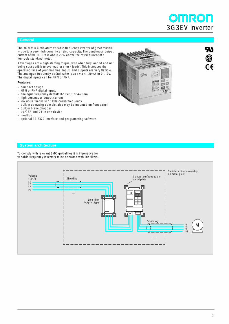
System architecture
To comply with relevant EMC guidelines it is imperative forvariable-frequency inverters to be operated with line filters.
L1L2L3PE
Line filter,footprint type
UVWPE
Shielding
Switch cabinet assemblyon metal plateVoltage
supply
M
ShieldingContact surfaces to themetal plate
3G3EV inverter
4
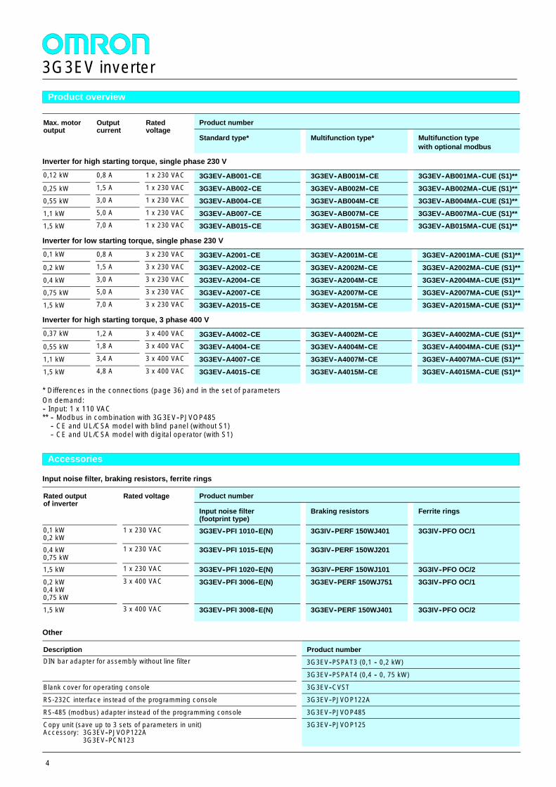
Product overview
Max. motoroutput
Outputcurrent
Ratedvoltage
Product numberMax. motoroutput
Outputcurrent
Ratedvoltage
Standard type* Multifunction type* Multifunction typewith optional modbus
Inverter for high starting torque, single phase 230 V
0,12 kW 0,8 A 1 x 230 VAC 3G3EV--AB001--CE 3G3EV--AB001M--CE 3G3EV--AB001MA--CUE (S1)**
0,25 kW 1,5 A 1 x 230 VAC 3G3EV--AB002--CE 3G3EV--AB002M--CE 3G3EV--AB002MA--CUE (S1)**0,55 kW 3,0 A 1 x 230 VAC 3G3EV--AB004--CE 3G3EV--AB004M--CE 3G3EV--AB004MA--CUE (S1)**
1,1 kW 5,0 A 1 x 230 VAC 3G3EV--AB007--CE 3G3EV--AB007M--CE 3G3EV--AB007MA--CUE (S1)**1,5 kW 7,0 A 1 x 230 VAC 3G3EV--AB015--CE 3G3EV--AB015M--CE 3G3EV--AB015MA--CUE (S1)**
Inverter for low starting torque, single phase 230 V
0,1 kW 0,8 A 3 x 230 VAC 3G3EV--A2001--CE 3G3EV--A2001M--CE 3G3EV--A2001MA--CUE (S1)**
0,2 kW 1,5 A 3 x 230 VAC 3G3EV--A2002--CE 3G3EV--A2002M--CE 3G3EV--A2002MA--CUE (S1)**
0,4 kW 3,0 A 3 x 230 VAC 3G3EV--A2004--CE 3G3EV--A2004M--CE 3G3EV--A2004MA--CUE (S1)**0,75 kW 5,0 A 3 x 230 VAC 3G3EV--A2007--CE 3G3EV--A2007M--CE 3G3EV--A2007MA--CUE (S1)**
1,5 kW 7,0 A 3 x 230 VAC 3G3EV--A2015--CE 3G3EV--A2015M--CE 3G3EV--A2015MA--CUE (S1)**
Inverter for high starting torque, 3 phase 400 V
0,37 kW 1,2 A 3 x 400 VAC 3G3EV--A4002--CE 3G3EV--A4002M--CE 3G3EV--A4002MA--CUE (S1)**0,55 kW 1,8 A 3 x 400 VAC 3G3EV--A4004--CE 3G3EV--A4004M--CE 3G3EV--A4004MA--CUE (S1)**
1,1 kW 3,4 A 3 x 400 VAC 3G3EV--A4007--CE 3G3EV--A4007M--CE 3G3EV--A4007MA--CUE (S1)**
1,5 kW 4,8 A 3 x 400 VAC 3G3EV--A4015--CE 3G3EV--A4015M--CE 3G3EV--A4015MA--CUE (S1)**
* Differences in the connections (page 36) and in the set of parametersOn demand:-- Input: 1 x 110 VAC** -- Modbus in combination with 3G3EV--PJVOP485
-- CE and UL/CSA model with blind panel (without S1)-- CE and UL/CSA model with digital operator (with S1)
Accessories
Input noise filter, braking resistors, ferrite rings
Rated outputof inverter
Rated voltage Product numberRated outputof inverter
Rated voltage
Input noise filter(footprint type)
Braking resistors Ferrite rings
0,1 kW0,2 kW
1 x 230 VAC 3G3EV--PFI 1010--E(N) 3G3IV--PERF 150WJ401 3G3IV--PFO OC/1
0,4 kW0,75 kW
1 x 230 VAC 3G3EV--PFI 1015--E(N) 3G3IV--PERF 150WJ201
1,5 kW 1 x 230 VAC 3G3EV--PFI 1020--E(N) 3G3IV--PERF 150WJ101 3G3IV--PFO OC/2
0,2 kW0,4 kW0,75 kW
3 x 400 VAC 3G3EV--PFI 3006--E(N) 3G3EV--PERF 150WJ751 3G3IV--PFO OC/1
1,5 kW 3 x 400 VAC 3G3EV--PFI 3008--E(N) 3G3EV--PERF 150WJ401 3G3IV--PFO OC/2
Other
Description Product numberDIN bar adapter for assembly without line filter 3G3EV--PSPAT3 (0,1 -- 0,2 kW)DIN bar adapter for assembly without line filter
3G3EV--PSPAT4 (0,4 -- 0, 75 kW)
Blank cover for operating console 3G3EV--CVSTRS-232C interface instead of the programming console 3G3EV--PJVOP122A
RS-485 (modbus) adapter instead of the programming console 3G3EV--PJVOP485Copy unit (save up to 3 sets of parameters in unit)Accessory: 3G3EV--PJVOP122A
3G3EV--PCN123
3G3EV--PJVOP125
3G3EV inverter
5
Programming accessories
PC programming Description Cable length Product numberPC programmingProgramming software under WINDOWS -- SYSDRIVE Configurator
RS-232C interface -- 3G3EV--PJVOP122A
Connecting cable 1 m3 m
3G3EV--PCN1223G3EV--PCN323
Technical data
230 V Class
Single-phase: 3G3EV--AB_MA--CUE AB001 AB002 AB004 AB007 AB015
Three-phase: 3G3EV--A2_M--E A2001 A2002 A2004 A2007 A2015Maximum allowed motor output kW 0,1 0,25 0,55 (0,4)* 1,1 (0,75)* 1,5 (1,1*)
Output data Inverter output kVA 0,3 0,6 1,1 1,9 2,6Output data
Output rated current A 0,8 1,5 3,0 5,0 7,0
Max. output voltage three-phase proportional to the input voltage: 200 to 240 V
Output frequency 0,5...400 Hz
Supply Rated input voltage andfrequency
single-phase: 200...240 V, 50/60 Hzthree-phase: 200...230 V, 50/60 Hz
Max. voltage variation --15 % to +10 %
Max. frequency variation + 5 %
Weight kg 0,6 0,9 1,3 1,3 2,0
* with single phase connection for EV--A2 type
400 V Class
3G3EV--A4_MA--CUE, input: three-phase A4002 A4004 A4007 A4015Maximum allowed motor output kW 0,37 0,55 1,1 1,5
Output data Inverter output kVA 0,9 1,4 2,6 3,7Output data
Output rated current A 1,2 1,8 3,4 4,8
Max. output voltage three-phase proportional to the input voltage: 380 to 460 V
Output frequency 0,5...400 Hz
Supply Rated input voltage andfrequency
three-phase: 380...460 V, 50/60 Hz
Max. voltage variation --15 % to +10 %
Max. frequency variation + 5 %
Weight kg 0,8 1,0 1,5 2,0
3G3EV inverter
6
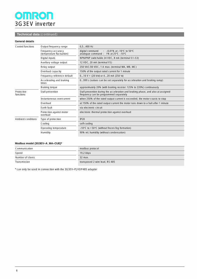
Technical data (continued)
General details
Control functions Output frequency range 0,5...400 HzControl functions
Frequency accuracy(temperature fluctuation)
digital command : ±0,01% at --10°C to 50°Canalogue command : 1% at 25°C ±10°C
Digital inputs NPN/PNP switchable 24 VDC, 8 mA (terminal S1--S3)
Auxiliary voltage output 12 VDC, 20 mA (terminal FS)
Relay output 250 VAC/30 VDC, 1 A max. (terminal MA, MB, MC)
Overload capacity 150% of the output rated current for 1 minute
Frequency reference default 0...10 V = (20 kW ) or 4...20 mA (250 W )
Accelerating and brakingtimes
0...999 s (values can be set separately for acceleration and braking ramp)
Braking torque approximately 20% (with braking resistor: 125% to 220%) continuously
Protectivefunctions
Stall prevention Stall prevention during the acceleration and braking phase, and also at assignedfrequency can be programmed separatelyfunctions
Instantaneous overcurrent when 250% of the rated output current is exceeded, the motor coasts to stop
Overload at 150% of the rated output current the motor runs down to a halt after 1 minute
Earth fault via electronic circuit
Protection against motoroverload
electronic thermal protection against overload
Ambient conditions Type of protection IP20Ambient conditions
Cooling self-cooling
Operating temperature --10°C to +50°C (without frozen-fog formation)
Humidity 90% rel. humidity (without condensation)
Modbus model (3G3EV--A_MA--CUE)*
Communication modbus protocol
Speed 19,2 kbps
Number of slaves 32 max.Transmission transposed 2 wire lead, RS-485
* can only be used in connection with the 3G3EV--PJVOP485 adapter
3G3EV inverter
7
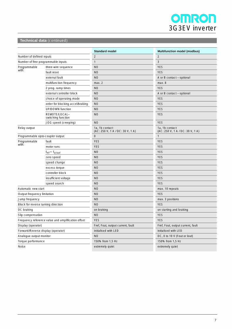
Technical data (continued)
Standard model Multifunction model (modbus)
Number of defined inputs 2 2
Number of free programmable inputs 1 3
Programmablewith:
three-wire sequence NO YESProgrammablewith: fault reset NO YES
external fault NO A or B contact –optional
multifunction frequency max. 2 max. 8
2 prog. ramp times NO YES
external controller block NO A or B contact –optional
choice of operating mode NO YES
order for blocking accel/braking NO YES
UP/DOWN function NO YES
REMOTE/LOCAL--switching function
NO YES
JOG speed (creeping) NO YES
Relay output 1a, 1b contact(AC: 250 V, 1 A / DC: 30 V, 1 A)
1a, 1b contact(AC: 250 V, 1 A / DC: 30 V, 1 A)
Programmable opto-coupler output 0 1
Programmablewith:
fault YES YESProgrammablewith: motor runs YES YES
fref = factual NO YES
zero speed NO YES
speed change NO YES
excess torque NO YES
controller block NO YES
insufficient voltage NO YES
speed search NO YES
Automatic new start NO max. 10 repeats
Output frequency limitation NO YES
Jump frequency NO max. 3 positions
Block for reverse turning direction NO YES
DC braking on braking on starting and braking
Slip compensation NO YES
Frequency reference value and amplification offset YES YES
Display (operator) Fref, Fout, output current, fault Fref, Fout, output current, fault
Forward/Reverse display (operator) initialised with LED initialised with LED
Analogue output monitor NO DC, 0 to 10 V (Fout or Iout)
Torque performance 150% from 1,5 Hz 150% from 1,5 Hz
Noise extremely quiet extremely quiet
3G3EV inverter
8
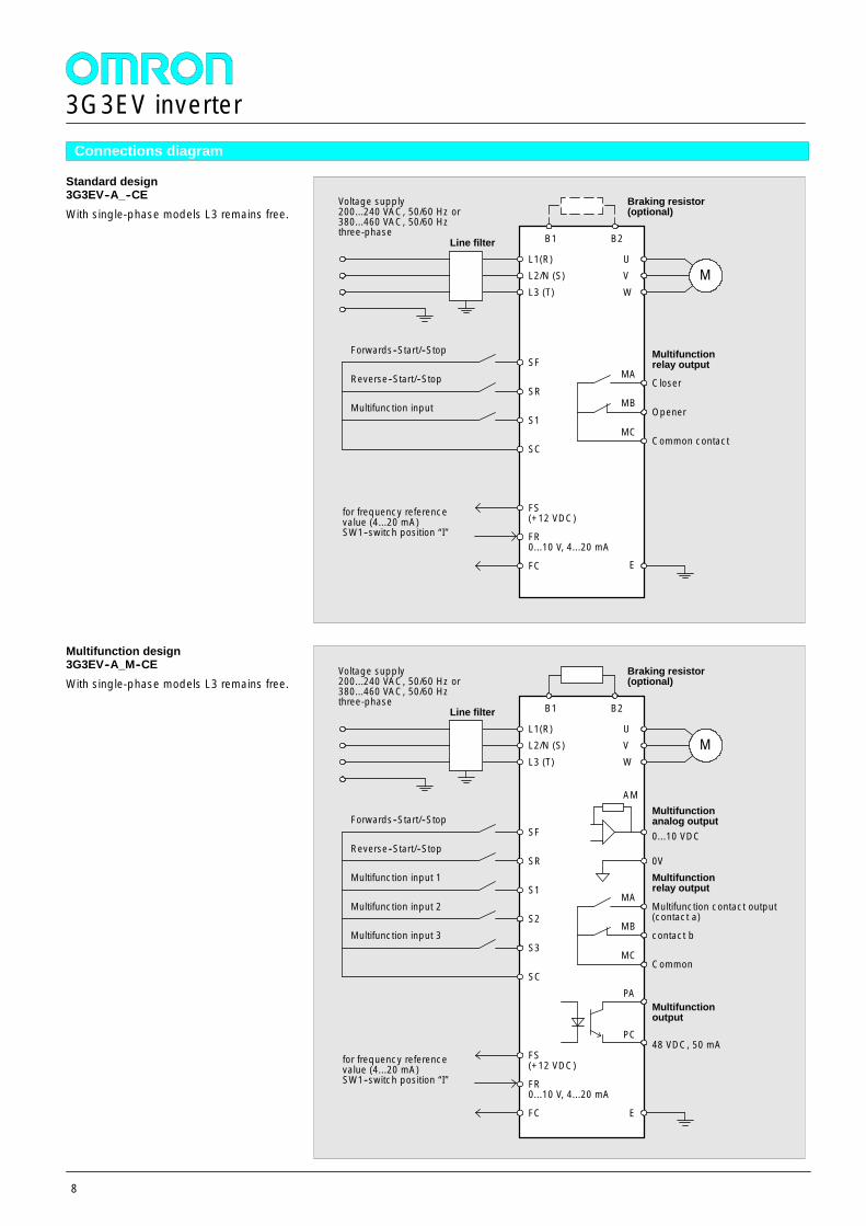
Connections diagram
Standard design3G3EV--A_--CEWith single-phase models L3 remains free.
Multifunction design3G3EV--A_M--CEWith single-phase models L3 remains free.
Forwards--Start/--Stop
Reverse--Start/--Stop
Multifunction input
SF
SR
S1
SC
FS(+12 VDC)
FR0...10 V, 4...20 mA
FC
for frequency referencevalue (4...20 mA)SW1--switch position “I”
L1(R)L2/N (S)L3 (T)
Line filter B1 B2
Braking resistor(optional)
M
MA
MB
MC
Closer
Opener
Common contact
UVW
Multifunctionrelay output
Voltage supply200...240 VAC, 50/60 Hz or380...460 VAC, 50/60 Hzthree-phase
E
MA
MB
MC
Multifunction contact output(contact a)
contact b
Common
Multifunctionrelay output
Forwards--Start/--Stop
Reverse--Start/--Stop
Multifunction input 1
Multifunction input 2
Multifunction input 3
Line filter
Voltage supply200...240 VAC, 50/60 Hz or380...460 VAC, 50/60 Hzthree-phase
SF
SR
S1
S2
S3
SC
L1(R)L2/N (S)L3 (T)
B1 B2
Braking resistor(optional)
MUVW
0...10 VDC
AMMultifunctionanalog output
PA
PC48 VDC, 50 mA
Multifunctionoutput
FS(+12 VDC)
FR0...10 V, 4...20 mA
FC
for frequency referencevalue (4...20 mA)SW1--switch position “I”
E
0V
3G3EV inverter
9
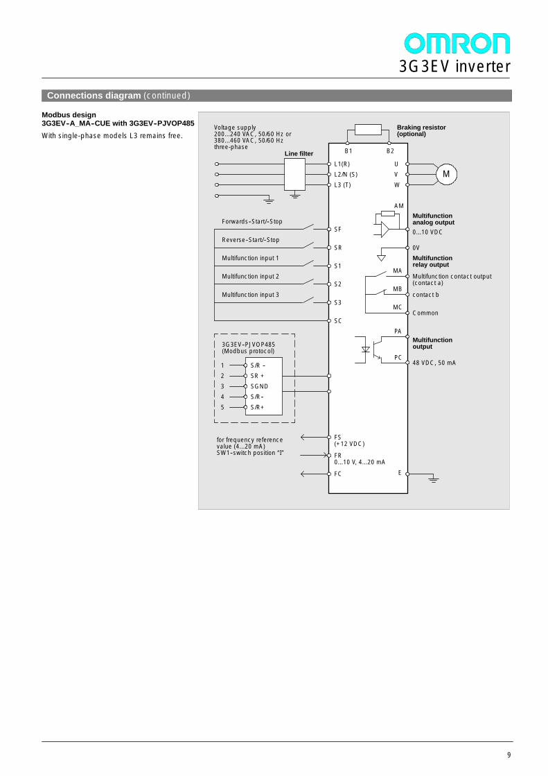
Connections diagram (continued)
Modbus design3G3EV--A_MA--CUE with 3G3EV--PJVOP485With single-phase models L3 remains free.
MA
MB
MC
Multifunction contact output(contact a)
contact b
Common
Multifunctionrelay output
Forwards--Start/--Stop
Reverse--Start/--Stop
Multifunction input 1
Multifunction input 2
Multifunction input 3
Line filter
Voltage supply200...240 VAC, 50/60 Hz or380...460 VAC, 50/60 Hzthree-phase
SF
SR
S1
S2
S3
SC
L1(R)L2/N (S)L3 (T)
B1 B2
Braking resistor(optional)
MUVW
0...10 VDC
AMMultifunctionanalog output
PA
PC48 VDC, 50 mA
Multifunctionoutput
12345
S/R --SR +SGNDS/R--S/R+
3G3EV--PJVOP485(Modbus protocol)
FS(+12 VDC)
FR0...10 V, 4...20 mA
FC
for frequency referencevalue (4...20 mA)SW1--switch position “I”
E
0V
3G3EV inverter
10
Technical documentation
Englishdocumentation
Product Title Product numberdocumentation
Standard type User Manual I011--E1--1A
SYSDRIVE INVERTER Multifunction Type User Manual I013--E1--2
Multifunction MA-CUE type User Manual I013--E2--1
OPERATION MANUAL
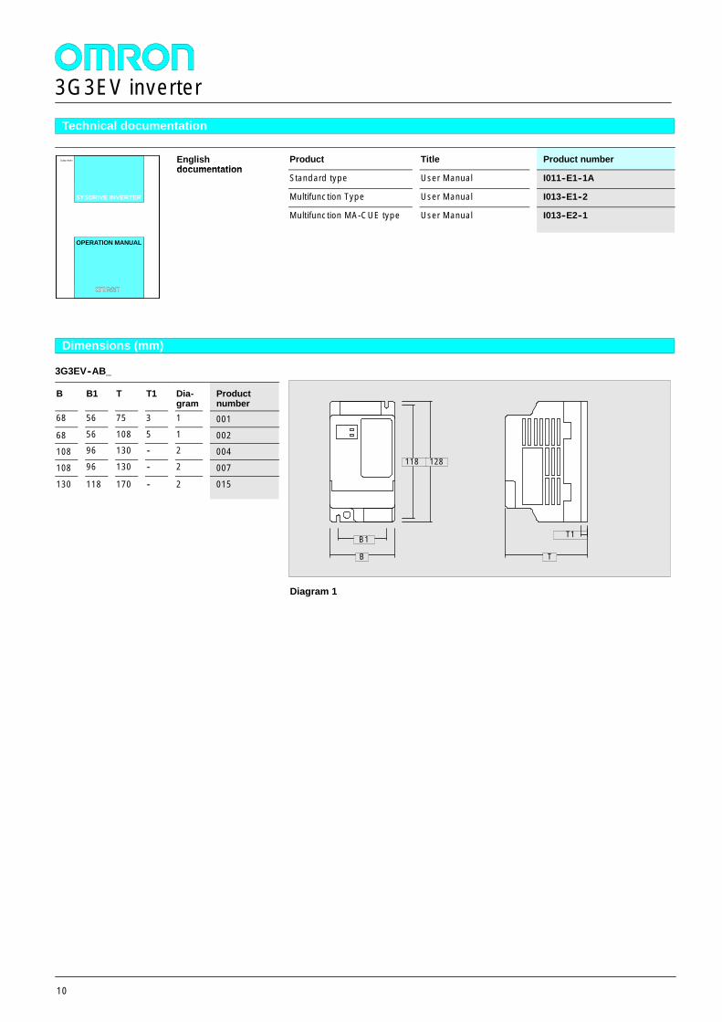
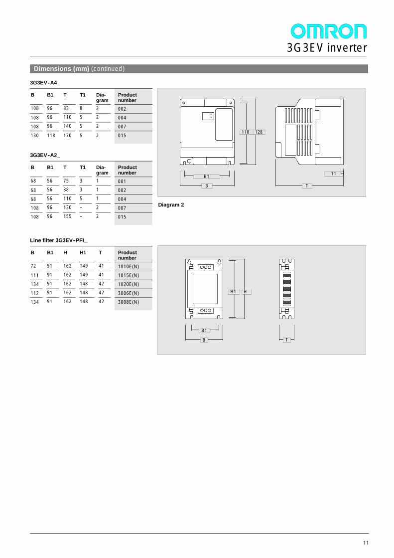
Dimensions (mm)
3G3EV--AB_
B B1 T T1 Dia-gram
Productnumber
68 56 75 3 1 001
68 56 108 5 1 002108 96 130 -- 2 004
108 96 130 -- 2 007
130 118 170 -- 2 015
T1
B
118
B1
128
T
Diagram 1
3G3EV inverter
11
Dimensions (mm) (continued)
3G3EV--A4_
B B1 T T1 Dia-gram
Productnumber
108 96 83 8 2 002108 96 110 5 2 004
108 96 140 5 2 007130 118 170 5 2 015
3G3EV--A2_
B B1 T T1 Dia-gram
Productnumber
68 56 75 3 1 00168 56 88 3 1 002
68 56 110 5 1 004
108 96 130 -- 2 007108 96 155 -- 2 015
Line filter 3G3EV--PFI_
B B1 H H1 T Productnumber
72 51 162 149 41 1010E(N)111 91 162 149 41 1015E(N)
134 91 162 148 42 1020E(N)
112 91 162 148 42 3006E(N)134 91 162 148 42 3008E(N)
T1
B
118
B1
128
T
Diagram 2
B
H1
B1
H
T

3G3EV inverter
12
3G3JV inverter
13
General
The 3G3JV is a miniature high--efficiency frequency inverter with anexcellent price-- performance relationship.The generous dimensions of the power section ensure a high startingtorque and low susceptibility to overload which increases machinereliability.Its many programmable inputs and outputs, an integrated potentio-meter for speed control and various monitor functions provide theinverter with high versatility and flexibility. The multifuntion inputs canbe set to either PNP or NPN. The analog inputs can be 0..10 V,4..20 mA or 0..20 mA.Features-- exceptionally compact design-- integrated reference value potentiometer-- modbus interface, optional-- 8 fixed frequencies-- 4 multifunction digital inputs-- 1 multifunction digital output-- 1 multifunction analog output-- Approval: CE, UL, CSA
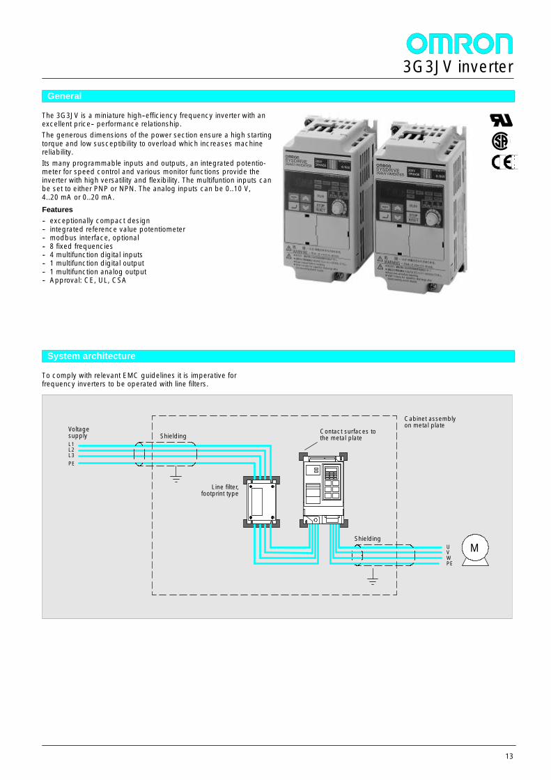
System architecture
To comply with relevant EMC guidelines it is imperative forfrequency inverters to be operated with line filters.
L1L2L3PE
Line filter,footprint type
UVWPE
Shielding
Cabinet assemblyon metal plateVoltage
supply
M
ShieldingContact surfaces tothe metal plate
3G3JV inverter
14
Product overview
Max. motoroutput
Outputcurrent
Ratedvoltage
Product numberMax. motoroutput
Outputcurrent
Ratedvoltage
Standard type
Single phase 230 V
0,1 kW 0,8 A 1 x 230 VAC 3G3JV--AB0010,25 kW 1,6 A 1 x 230 VAC 3G3JV--AB0020,55 kW 3,0 A 1 x 230 VAC 3G3JV--AB0041,1 kW 5,0 A 1 x 230 VAC 3G3JV--AB0071,5 kW 8,0 A 1 x 230 VAC 3G3JV--AB015Three phase 230 V
0,1 kW 0,8 A 3 x 230 VAC 3G3JV--A20010,25 kW 1,6 A 3 x 230 VAC 3G3JV--A20020,55 kW 3,0 A 3 x 230 VAC 3G3JV--A20041,1 kW 5,0 A 3 x 230 VAC 3G3JV--A20071,5 kW 8,0 A 3 x 230 VAC 3G3JV--A20152,2 kW 11 A 3 x 230 VAC 3G3JV--A20224,0 kW 11 A 3 x 230 VAC 3G3JV--A2040Three phase 400 V
0,37 kW 1,2 A 3 x 400 VAC 3G3JV--A40020,55 kW 1,8 A 3 x 400 VAC 3G3JV--A40041,1 kW 3,4 A 3 x 400 VAC 3G3JV--A40071,5 kW 4,8 A 3 x 400 VAC 3G3JV--A40152,2 kW 5,5 A 3 x 400 VAC 3G3JV--A40223,0 kW 7,2 A 3 x 400 VAC 3G3JV--A40304,0 kW 9,2 A 3 x 400 VAC 3G3JV--A4040
Accessories
Line filter, braking resistors, ferrite rings, DIN track mounting bracket
Inverter Product numberInverter
Line filter (footprint filter) Ferrite rings DIN track mounting bracket
3G3JV--AB001 3G3JV--PFI1010--E 3G3IV--PFO OC/1 3G3IV--PZZ08122A
3G3JV--AB002 3G3JV--PFI1010--E 3G3IV--PFO OC/1 3G3IV--PZZ08122A
3G3JV--AB004 3G3JV--PFI1010--E 3G3IV--PFO OC/1 3G3IV--PZZ08122A
3G3JV--AB007 3G3JV--PFI1020--E 3G3IV--PFO OC/1 3G3IV--PZZ08122B
3G3JV--AB015 3G3JV--PFI1020--E 3G3IV--PFO OC/2 3G3IV--PZZ08122B3G3JV--A2001 3G3JV--PFI2010--E 3G3IV--PFO OC/1 3G3IV--PZZ08122A
3G3JV--A2002 3G3JV--PFI2010--E 3G3IV--PFO OC/1 3G3IV--PZZ08122A3G3JV--A2004 3G3JV--PFI2010--E 3G3IV--PFO OC/1 3G3IV--PZZ08122A
3G3JV--A2007 3G3JV--PFI2010--E 3G3IV--PFO OC/1 3G3IV--PZZ08122A
3G3JV--A2015 3G3JV--PFI2020--E 3G3IV--PFO OC/2 3G3IV--PZZ08122B3G3JV--A2022 3G3JV--PFI2020--E 3G3IV--PFO OC/2 3G3IV--PZZ08122B
3G3JV--A2040 3G3JV--PFI2030--E 3G3IV--PFO OC/2 3G3IV--PZZ08122C3G3JV--A4002 3G3JV--PFI3005--E 3G3IV--PFO OC/1 3G3IV--PZZ08122B
3G3JV--A4004 3G3JV--PFI3005--E 3G3IV--PFO OC/1 3G3IV--PZZ08122B
3G3JV--A4007 3G3JV--PFI3010--E 3G3IV--PFO OC/1 3G3IV--PZZ08122B3G3JV--A4015 3G3JV--PFI3010--E 3G3IV--PFO OC/2 3G3IV--PZZ08122B
3G3JV--A4022 3G3JV--PFI3010--E 3G3IV--PFO OC/2 3G3IV--PZZ08122B
3G3JV--A4030 3G3JV--PFI3020--E 3G3IV--PFO OC/2 3G3IV--PZZ08122C3G3JV--A4040 3G3JV--PFI3020--E 3G3IV--PFO OC/2 3G3IV--PZZ08122C
3G3JV inverter
15
Technical data
230 V class
Single phase: 3G3JV--AB AB001 AB002 AB004 AB007 AB015
Three phase: 3G3JV--A2 A2001 A2002 A2004 A2007 A2015 A2022 A2040Maximum allowed motor output kW 0,12 0,25 0,55
(0,4*)1,1(0,75*)
1,5 (1,1*) 2,2 4,0
Output data Inverter output kVA 0,3 0,6 1,1 1,9 3,0 4,2 6,7Output data
Output rated current A 0,8 1,6 3,0 5,0 8,0 11,0 17,5
Max. output voltage proportional to the input voltage: 0..240 V
Output frequencies 400 Hz
Supply Rated input voltage andfrequency
200..240 V, 50/60 Hz
Max. voltage variation --15 % to +10 %
Max. frequency variation + 5 %
* With single phase connection for JV--A2 type s
400 V class
Three phase: 3G3JV--A4 A4002 A4004 A4007 A4015 A4022 A4030 A4040Maximum allowed motor output kW 0,37 0,55 1,1 1,5 2,2 3,0 4,0
Output data Inverter output kVA 0,9 1,4 2,6 3,7 4,2 5,5 7,0Output data
Output rated current A 1,2 1,8 3,4 4,8 5,5 7,2 9,2
Max. output voltage proportional to the input voltage: 0..460 V
Output frequencies 400 Hz
Supply Rated input voltage andfrequency
3--phase, 380..460 V, 50/60 Hz
Max. voltage variation --15 % to +10 %
Max. frequency variation + /- 5 %
* With single phase connection for JV--A2 type s
3G3JV inverter
16
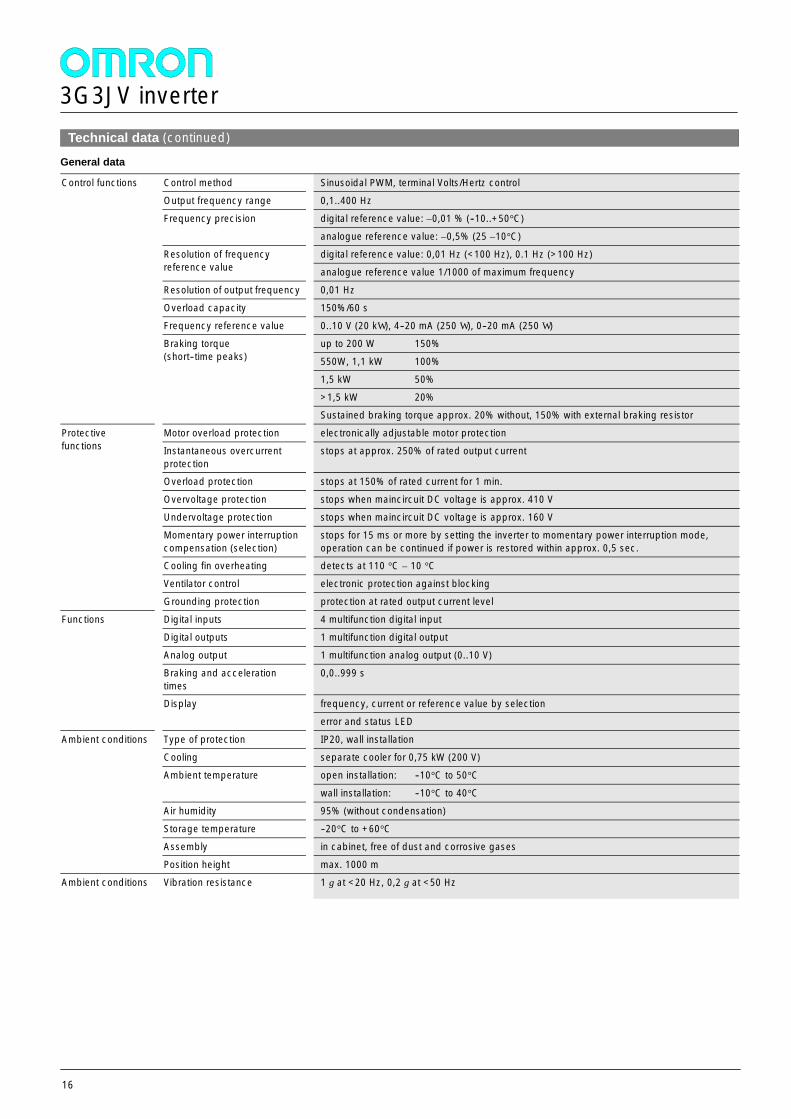
Technical data (continued)General data
Control functions Control method Sinusoidal PWM, terminal Volts/Hertz controlControl functions
Output frequency range 0,1..400 Hz
Frequency precision digital reference value: ±0,01 % (--10..+50°C)Frequency precision
analogue reference value: ±0,5% (25 ±10°C)
Resolution of frequencyreference value
digital reference value: 0,01 Hz (<100 Hz), 0.1 Hz (>100 Hz)Resolution of frequencyreference value analogue reference value 1/1000 of maximum frequency
Resolution of output frequency 0,01 Hz
Overload capacity 150%/60 s
Frequency reference value 0..10 V (20 kW ), 4--20 mA (250 W ), 0--20 mA (250 W )
Braking torque(short--time peaks)
up to 200 W 150%Braking torque(short--time peaks) 550W, 1,1 kW 100%
1,5 kW 50%
>1,5 kW 20%
Sustained braking torque approx. 20% without, 150% with external braking resistor
Protectivefunctions
Motor overload protection electronically adjustable motor protectionProtectivefunctions Instantaneous overcurrent
protectionstops at approx. 250% of rated output current
Overload protection stops at 150% of rated current for 1 min.
Overvoltage protection stops when maincircuit DC voltage is approx. 410 V
Undervoltage protection stops when maincircuit DC voltage is approx. 160 V
Momentary power interruptioncompensation (selection)
stops for 15 ms or more by setting the inverter to momentary power interruption mode,operation can be continued if power is restored within approx. 0,5 sec.
Cooling fin overheating detects at 110 °C ±10 °C
Ventilator control electronic protection against blocking
Grounding protection protection at rated output current level
Functions Digital inputs 4 multifunction digital inputFunctions
Digital outputs 1 multifunction digital output
Analog output 1 multifunction analog output (0..10 V)
Braking and accelerationtimes
0,0..999 s
Display frequency, current or reference value by selectionDisplay
error and status LED
Ambient conditions Type of protection IP20, wall installationAmbient conditions
Cooling separate cooler for 0,75 kW (200 V)
Ambient temperature open installation: --10°C to 50°CAmbient temperature
wall installation: --10°C to 40°C
Air humidity 95% (without condensation)
Storage temperature --20°C to +60°C
Assembly in cabinet, free of dust and corrosive gases
Position height max. 1000 m
Ambient conditions Vibration resistance 1 g at <20 Hz, 0,2 g at <50 Hz
3G3JV inverter
17
Connections diagram
L3 remains free with single--phase equipment
MA
MB
MC
Closer
Opener
Common contact
Multifunctionrelay output
Forwards--Start--Stop
Multifunction input 1
Multifunction input 2
Multifunction input 3
Multifunction input 4
Line filter
Voltage supply200...240 VAC, 50/60 Hz,single--phase
S1
S2
S3
S4
S5
L1(R)L2/N (S) M
UVW
0..10 VDC
AMMultifunctionanalog output
FS(+12 VDC)
FR0..10 V, 4..20 mA
FC
Frequency referencevalue
E
0VAC
Reference potentialMultifunction inputs
3G3JV inverter
18
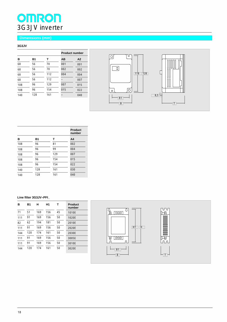
Dimensions (mm)
3G3JV
Product number
B B1 T AB A268 56 70 001 00168 56 70 002 002
68 56 112 004 004
68 56 112 -- 007108 96 129 007 015
108 96 154 015 022140 128 161 -- 040
Productnumber
B B1 T A4108 96 81 002
108 96 99 004
108 96 129 007
108 96 154 015
108 96 154 022
140 128 161 030
140 128 161 040
Line filter 3G3JV--PFI_
B B1 H H1 T Productnumber
71 51 169 156 45 1010E111 91 169 156 50 1020E
82 62 194 181 50 2010E
111 91 169 156 50 2020E144 120 174 161 50 2030E
111 91 169 156 50 3005E
111 91 169 156 50 3010E144 120 174 161 50 3020E
8,5
B
118
B1
128
T
B
H1
B1
H
T
3G3JV inverter
19
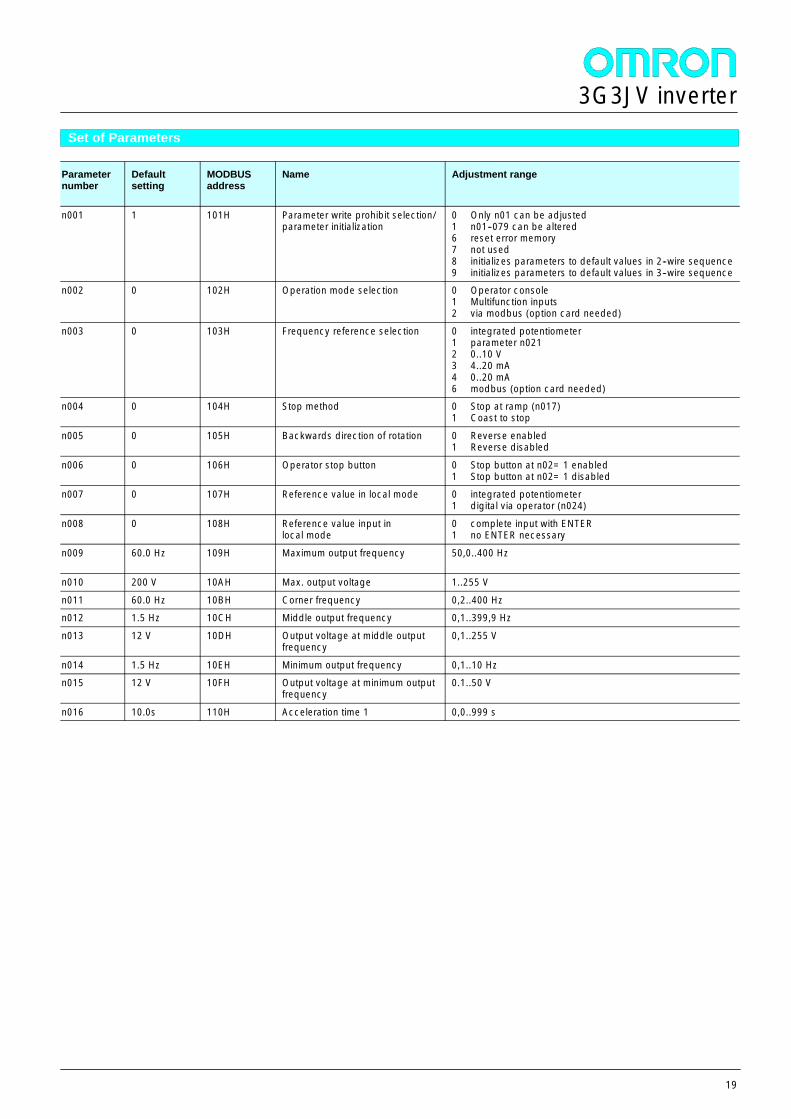
Set of Parameters
Parameternumber
Defaultsetting
MODBUSaddress
Name Adjustment range
n001 1 101H Parameter write prohibit selection/parameter initialization
0 Only n01 can be adjusted1 n01--079 can be altered6 reset error memory7 not used8 initializes parameters to default values in 2--wire sequence9 initializes parameters to default values in 3--wire sequence
n002 0 102H Operation mode selection 0 Operator console1 Multifunction inputs2 via modbus (option card needed)
n003 0 103H Frequency reference selection 0 integrated potentiometer1 parameter n0212 0..10 V3 4..20 mA4 0..20 mA6 modbus (option card needed)
n004 0 104H Stop method 0 Stop at ramp (n017)1 Coast to stop
n005 0 105H Backwards direction of rotation 0 Reverse enabled1 Reverse disabled
n006 0 106H Operator stop button 0 Stop button at n02= 1 enabled1 Stop button at n02= 1 disabled
n007 0 107H Reference value in local mode 0 integrated potentiometer1 digital via operator (n024)
n008 0 108H Reference value input inlocal mode
0 complete input with ENTER1 no ENTER necessary
n009 60.0 Hz 109H Maximum output frequency 50,0..400 Hz
n010 200 V 10AH Max. output voltage 1..255 V
n011 60.0 Hz 10BH Corner frequency 0,2..400 Hzn012 1.5 Hz 10CH Middle output frequency 0,1..399,9 Hz
n013 12 V 10DH Output voltage at middle outputfrequency
0,1..255 V
n014 1.5 Hz 10EH Minimum output frequency 0,1..10 Hzn015 12 V 10FH Output voltage at minimum output
frequency0.1..50 V
n016 10.0s 110H Acceleration time 1 0,0..999 s
3G3JV inverter
20
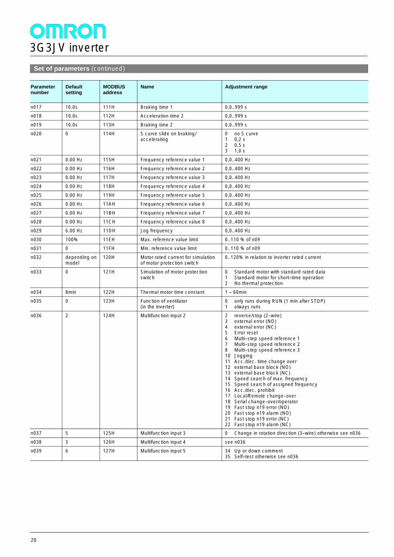
Set of parameters (continued)
Parameternumber
Defaultsetting
MODBUSaddress
Name Adjustment range
n017 10.0s 111H Braking time 1 0,0..999 sn018 10.0s 112H Acceleration time 2 0,0..999 s
n019 10.0s 113H Braking time 2 0,0..999 sn020 0 114H S curve slide on braking/
accelerating0 no S curve1 0,2 s2 0,5 s3 1,0 s
n021 0.00 Hz 115H Frequency reference value 1 0,0..400 Hz
n022 0.00 Hz 116H Frequency reference value 2 0,0..400 Hzn023 0.00 Hz 117H Frequency reference value 3 0,0..400 Hz
n024 0.00 Hz 118H Frequency reference value 4 0,0..400 Hz
n025 0.00 Hz 119H Frequency reference value 5 0,0..400 Hzn026 0.00 Hz 11AH Frequency reference value 6 0,0..400 Hz
n027 0.00 Hz 11BH Frequency reference value 7 0,0..400 Hzn028 0.00 Hz 11CH Frequency reference value 8 0,0..400 Hz
n029 6.00 Hz 11DH Jog frequency 0,0..400 Hz
n030 100% 11EH Max. reference value limit 0..110 % of n09n031 0 11FH Min. reference value limit 0..110 % of n09
n032 depending onmodel
120H Motor rated current for simulationof motor protection switch
0..120% in relation to inverter rated current
n033 0 121H Simulation of motor protectionswitch
0 Standard motor with standard rated data1 Standard motor for short--time operation2 No thermal protection
n034 8min 122H Thermal motor time constant 1 -- 60min
n035 0 123H Function of ventilator(in the inverter)
0 only runs during RUN (1 min after STOP)1 always runs
n036 2 124H Multifunction input 2 2 reverse/stop (2--wire)3 external error (NO)4 external error (NC)5 Error reset6 Multi--step speed reference 17 Multi--step speed reference 28 Multi--step speed reference 310 Jogging11 Acc./dec. time change over12 external base block (NO)13 external base block (NC)14 Speed search of max. frequency15 Speed search of assigned frequency16 Acc./dec. prohibit17 Local/Remote change--over18 Serial change--over/operator19 Fast stop n19 error (NO)20 Fast stop n19 alarm (NO)21 Fast stop n19 error (NC)22 Fast stop n19 alarm (NC)
n037 5 125H Multifunction input 3 0 Change in rotation direction (3--wire) otherwise see n036
n038 3 126H Multifunction input 4 see n036n039 6 127H Multifunction input 5 34 Up or down comment
35 Self--test otherwise see n036
3G3JV inverter
21
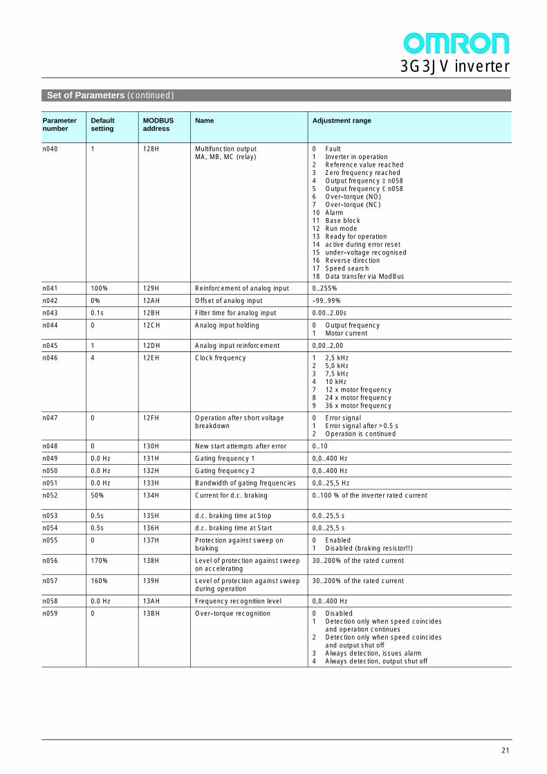
Set of Parameters (continued)
Parameternumber
Defaultsetting
MODBUSaddress
Name Adjustment range
n040 1 128H Multifunction outputMA, MB, MC (relay)
0 Fault1 Inverter in operation2 Reference value reached3 Zero frequency reached4 Output frequency ³ n0585 Output frequency £n0586 Over--torque (NO)7 Over--torque (NC)10 Alarm11 Base block12 Run mode13 Ready for operation14 active during error reset15 under--voltage recognised16 Reverse direction17 Speed search18 Data transfer via ModBus
n041 100% 129H Reinforcement of analog input 0..255%
n042 0% 12AH Offset of analog input --99..99%n043 0.1s 12BH Filter time for analog input 0.00..2.00s
n044 0 12CH Analog input holding 0 Output frequency1 Motor current
n045 1 12DH Analog input reinforcement 0,00..2,00n046 4 12EH Clock frequency 1 2,5 kHz
2 5,0 kHz3 7,5 kHz4 10 kHz7 12 x motor frequency8 24 x motor frequency9 36 x motor frequency
n047 0 12FH Operation after short voltagebreakdown
0 Error signal1 Error signal after >0.5 s2 Operation is continued
n048 0 130H New start attempts after error 0..10n049 0.0 Hz 131H Gating frequency 1 0,0..400 Hz
n050 0.0 Hz 132H Gating frequency 2 0,0..400 Hzn051 0.0 Hz 133H Bandwidth of gating frequencies 0,0..25,5 Hz
n052 50% 134H Current for d.c. braking 0..100 % of the inverter rated current
n053 0.5s 135H d.c. braking time at Stop 0,0..25,5 sn054 0.5s 136H d.c. braking time at Start 0,0..25,5 s
n055 0 137H Protection against sweep onbraking
0 Enabled1 Disabled (braking resistor!!)
n056 170% 138H Level of protection against sweepon accelerating
30..200% of the rated current
n057 160% 139H Level of protection against sweepduring operation
30..200% of the rated current
n058 0.0 Hz 13AH Frequency recognition level 0,0..400 Hzn059 0 13BH Over--torque recognition 0 Disabled
1 Detection only when speed coincidesand operation continues
2 Detection only when speed coincidesand output shut off
3 Always detection, issues alarm4 Always detection, output shut off
3G3JV inverter
22
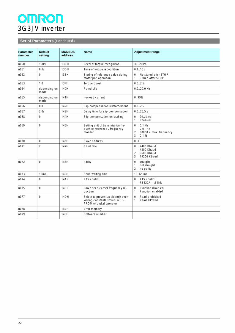
Set of Parameters (continued)
Parameternumber
Defaultsetting
MODBUSaddress
Name Adjustment range
n060 160% 13CH Level of torque recognition 30..200%n061 0.1s 13DH Time of torque recognition 0,1..10 s
n062 0 13EH Storing of reference value duringmotor poti operation
0 No stored after STOP1 Stored after STOP
n063 1.0 13FH Torque boost 0,0..2,5
n064 depending onmodel
140H Rated slip 0,0..20.0 Hz
n065 depending onmodel
141H no--load current 0..99%
n066 0.0 142H Slip compensation reinforcement 0,0..2.5
n067 2.0s 143H Delay time for slip compensation 0,0..25,5 s
n068 0 144H Slip compensation on braking 0 Disabled1 Enabled
n069 0 145H Setting unit of transmission fre-quence reference / frequencymonitor
0 0,1 Hz1 0,01 Hz2 30000 = max. frequency3 0,1 %
n070 0 146H Slave address 0..1n071 2 147H Baud rate 0 2400 Kbaud
1 4800 Kbaud2 9600 Kbaud3 19200 Kbaud
n072 0 148H Parity 0 straight1 not straight2 no parity
n073 10ms 149H Send waiting time 10..65 msn074 0 14AH RTS control 0 RTS control
1 RS422A, 1:1 link
n075 0 14BH Low speed carrier frequency re-duction
0 Function disabled1 Function enabled
n077 0 14DH Select to prevent accidently over-writing constants stored in EE-PROM or digital operator
0 Read prohibited1 Read allowed
n078 14EH Error memory
n079 14FH Software number
3G3MV inverter
23
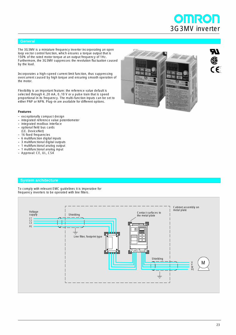
General
The 3G3MV is a miniature frequency inverter incorperating an openloop vector control function, which ensures a torque output that is150% of the rated motor torque at an output frequency of 1Hz.Furthermore, the 3G3MV suppresses the revolution fluctuation causedby the load.
Incorporates a high--speed current limit function, thus suppressingovercurrent caused by high torque and ensuring smooth operation ofthe motor.
Flexibility is an important feature: the reference value default isselected through 4..20 mA, 0..10 V or a pulse train that is speedproportional in its frequency. The multi--function inputs can be set toeither PNP or NPN. Plug--in are available for different options.
Features-- exceptionally compact design-- integrated reference value potentiometer-- integrated modbus interface-- optional field bus cards
(I.E. DeviceNet)-- 16 fixed frequencies-- 6 multifunction digital inputs-- 3 multifunctional digital outputs-- 1 multifunctional analog output-- 1 multifunctional analog input-- Approval: CE, UL, CSA
System architecture
To comply with relevant EMC guidelines it is imperative forfrequency inverters to be operated with line filters.
L1L2L3PE
Line filter, footprint type
UVWPE
Shielding
Cabinet assembly onmetal plateVoltage
supply
M
ShieldingContact surfaces tothe metal plate
3G3MV inverter
24
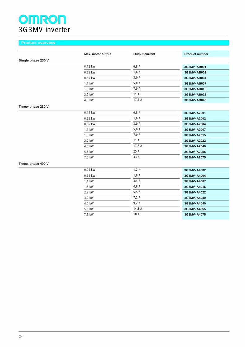
Product overview
Max. motor output Output current Product number
Single phase 230 V
0,12 kW 0,8 A 3G3MV--AB001
0,25 kW 1,6 A 3G3MV--AB002
0,55 kW 3,0 A 3G3MV--AB004
1,1 kW 5,0 A 3G3MV--AB007
1,5 kW 7,0 A 3G3MV--AB015
2,2 kW 11 A 3G3MV--AB022
4,0 kW 17,5 A 3G3MV--AB040
Three--phase 230 V
0,12 kW 0,8 A 3G3MV--A2001
0,25 kW 1,6 A 3G3MV--A2002
0,55 kW 3,0 A 3G3MV--A2004
1,1 kW 5,0 A 3G3MV--A2007
1,5 kW 7,0 A 3G3MV--A2015
2,2 kW 11 A 3G3MV--A2022
4,0 kW 17,5 A 3G3MV--A2040
5,5 kW 25 A 3G3MV--A2055
7,5 kW 33 A 3G3MV--A2075
Three--phase 400 V
0,25 kW 1,2 A 3G3MV--A4002
0,55 kW 1,8 A 3G3MV--A4004
1,1 kW 3,4 A 3G3MV--A4007
1,5 kW 4,8 A 3G3MV--A4015
2,2 kW 5,5 A 3G3MV--A4022
3,0 kW 7,2 A 3G3MV--A4030
4,0 kW 9,2 A 3G3MV--A4040
5,5 kW 14,8 A 3G3MV--A4055
7,5 kW 18 A 3G3MV--A4075
3G3MV inverter
25
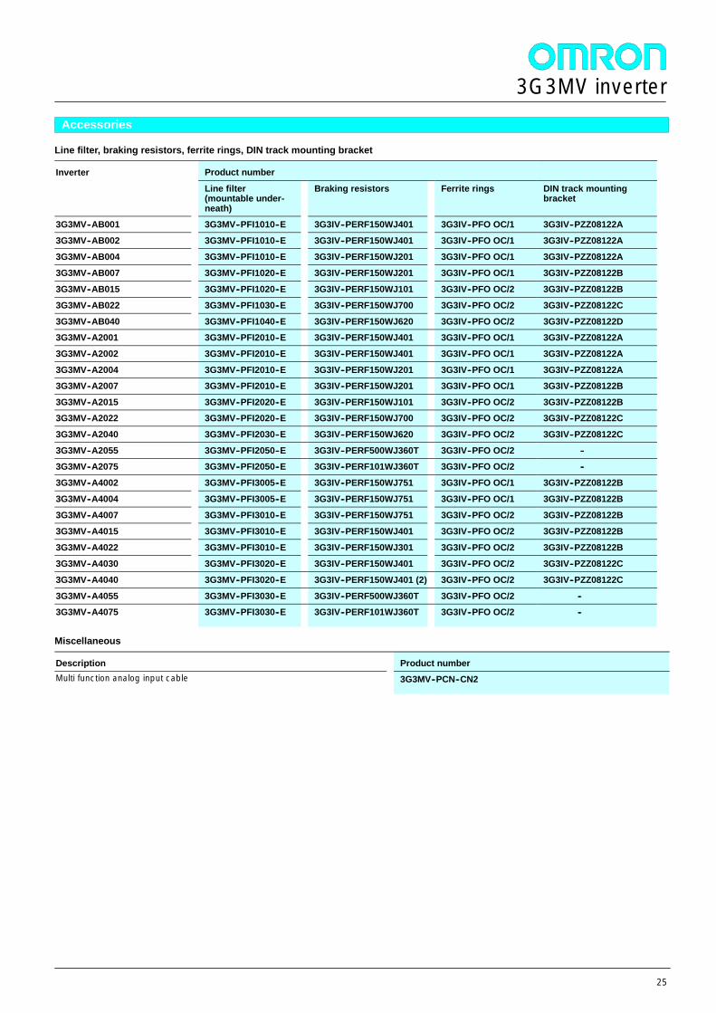
Accessories
Line filter, braking resistors, ferrite rings, DIN track mounting bracket
Inverter Product numberInverter
Line filter(mountable under-neath)
Braking resistors Ferrite rings DIN track mountingbracket
3G3MV--AB001 3G3MV--PFI1010--E 3G3IV--PERF150WJ401 3G3IV--PFO OC/1 3G3IV--PZZ08122A
3G3MV--AB002 3G3MV--PFI1010--E 3G3IV--PERF150WJ401 3G3IV--PFO OC/1 3G3IV--PZZ08122A
3G3MV--AB004 3G3MV--PFI1010--E 3G3IV--PERF150WJ201 3G3IV--PFO OC/1 3G3IV--PZZ08122A
3G3MV--AB007 3G3MV--PFI1020--E 3G3IV--PERF150WJ201 3G3IV--PFO OC/1 3G3IV--PZZ08122B
3G3MV--AB015 3G3MV--PFI1020--E 3G3IV--PERF150WJ101 3G3IV--PFO OC/2 3G3IV--PZZ08122B
3G3MV--AB022 3G3MV--PFI1030--E 3G3IV--PERF150WJ700 3G3IV--PFO OC/2 3G3IV--PZZ08122C
3G3MV--AB040 3G3MV--PFI1040--E 3G3IV--PERF150WJ620 3G3IV--PFO OC/2 3G3IV--PZZ08122D3G3MV--A2001 3G3MV--PFI2010--E 3G3IV--PERF150WJ401 3G3IV--PFO OC/1 3G3IV--PZZ08122A
3G3MV--A2002 3G3MV--PFI2010--E 3G3IV--PERF150WJ401 3G3IV--PFO OC/1 3G3IV--PZZ08122A
3G3MV--A2004 3G3MV--PFI2010--E 3G3IV--PERF150WJ201 3G3IV--PFO OC/1 3G3IV--PZZ08122A3G3MV--A2007 3G3MV--PFI2010--E 3G3IV--PERF150WJ201 3G3IV--PFO OC/1 3G3IV--PZZ08122B
3G3MV--A2015 3G3MV--PFI2020--E 3G3IV--PERF150WJ101 3G3IV--PFO OC/2 3G3IV--PZZ08122B3G3MV--A2022 3G3MV--PFI2020--E 3G3IV--PERF150WJ700 3G3IV--PFO OC/2 3G3IV--PZZ08122C
3G3MV--A2040 3G3MV--PFI2030--E 3G3IV--PERF150WJ620 3G3IV--PFO OC/2 3G3IV--PZZ08122C
3G3MV--A2055 3G3MV--PFI2050--E 3G3IV--PERF500WJ360T 3G3IV--PFO OC/2 --3G3MV--A2075 3G3MV--PFI2050--E 3G3IV--PERF101WJ360T 3G3IV--PFO OC/2 --
3G3MV--A4002 3G3MV--PFI3005--E 3G3IV--PERF150WJ751 3G3IV--PFO OC/1 3G3IV--PZZ08122B
3G3MV--A4004 3G3MV--PFI3005--E 3G3IV--PERF150WJ751 3G3IV--PFO OC/1 3G3IV--PZZ08122B
3G3MV--A4007 3G3MV--PFI3010--E 3G3IV--PERF150WJ751 3G3IV--PFO OC/2 3G3IV--PZZ08122B
3G3MV--A4015 3G3MV--PFI3010--E 3G3IV--PERF150WJ401 3G3IV--PFO OC/2 3G3IV--PZZ08122B
3G3MV--A4022 3G3MV--PFI3010--E 3G3IV--PERF150WJ301 3G3IV--PFO OC/2 3G3IV--PZZ08122B
3G3MV--A4030 3G3MV--PFI3020--E 3G3IV--PERF150WJ401 3G3IV--PFO OC/2 3G3IV--PZZ08122C
3G3MV--A4040 3G3MV--PFI3020--E 3G3IV--PERF150WJ401 (2) 3G3IV--PFO OC/2 3G3IV--PZZ08122C
3G3MV--A4055 3G3MV--PFI3030--E 3G3IV--PERF500WJ360T 3G3IV--PFO OC/2 --3G3MV--A4075 3G3MV--PFI3030--E 3G3IV--PERF101WJ360T 3G3IV--PFO OC/2 --
Miscellaneous
Description Product numberMulti function analog input cable 3G3MV--PCN--CN2
3G3MV inverter
26
Accessories (continued)Miscellaneous
Description Product numberOption card holder on demand
Option cards-- CAN--Bus-- DeviceNet-- Interbus S-- PROFIBUS DP
on demand
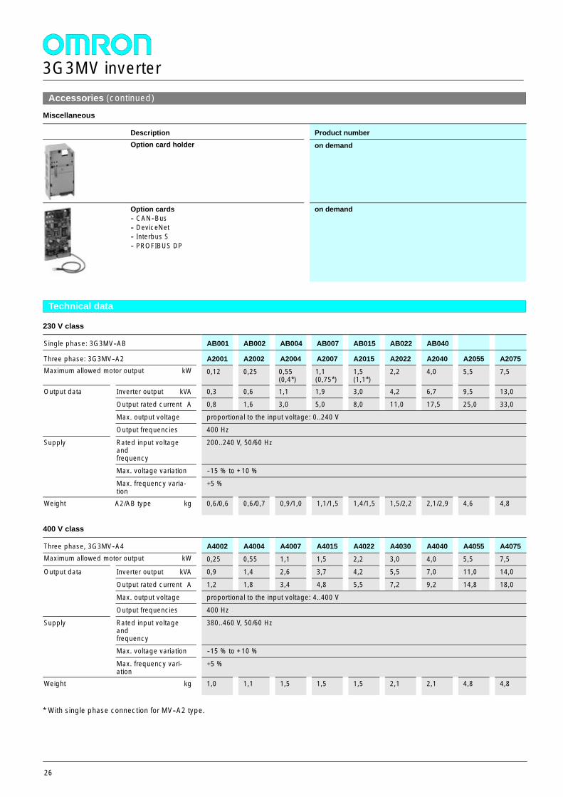
Technical data
230 V class
Single phase: 3G3MV--AB AB001 AB002 AB004 AB007 AB015 AB022 AB040
Three phase: 3G3MV--A2 A2001 A2002 A2004 A2007 A2015 A2022 A2040 A2055 A2075Maximum allowed motor output kW 0,12 0,25 0,55
(0,4*)1,1(0,75*)
1,5(1,1*)
2,2 4,0 5,5 7,5
Output data Inverter output kVA 0,3 0,6 1,1 1,9 3,0 4,2 6,7 9,5 13,0Output data
Output rated current A 0,8 1,6 3,0 5,0 8,0 11,0 17,5 25,0 33,0
Max. output voltage proportional to the input voltage: 0..240 V
Output frequencies 400 Hz
Supply Rated input voltageandfrequency
200..240 V, 50/60 Hz
Max. voltage variation --15 % to +10 %
Max. frequency varia-tion
+ 5 %
Weight A2/AB type kg 0,6/0,6 0,6/0,7 0,9/1,0 1,1/1,5 1,4/1,5 1,5/2,2 2,1/2,9 4,6 4,8
400 V class
Three phase, 3G3MV--A4 A4002 A4004 A4007 A4015 A4022 A4030 A4040 A4055 A4075Maximum allowed motor output kW 0,25 0,55 1,1 1,5 2,2 3,0 4,0 5,5 7,5
Output data Inverter output kVA 0,9 1,4 2,6 3,7 4,2 5,5 7,0 11,0 14,0Output data
Output rated current A 1,2 1,8 3,4 4,8 5,5 7,2 9,2 14,8 18,0
Max. output voltage proportional to the input voltage: 4..400 V
Output frequencies 400 Hz
Supply Rated input voltageandfrequency
380..460 V, 50/60 Hz
Max. voltage variation --15 % to +10 %
Max. frequency vari-ation
+ 5 %
Weight kg 1,0 1,1 1,5 1,5 1,5 2,1 2,1 4,8 4,8
* With single phase connection for MV--A2 type.
3G3MV inverter
27
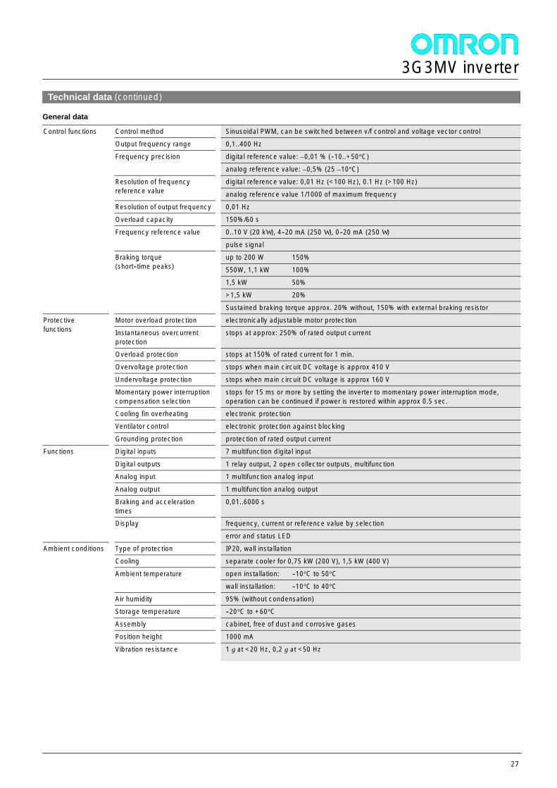
Technical data (continued)
General data
Control functions Control method Sinusoidal PWM, can be switched between v/f control and voltage vector controlControl functions
Output frequency range 0,1..400 Hz
Frequency precision digital reference value: ±0,01 % (--10..+50°C)Frequency precision
analog reference value: ±0,5% (25 ±10°C)
Resolution of frequencyreference value
digital reference value: 0,01 Hz (<100 Hz), 0.1 Hz (>100 Hz)Resolution of frequencyreference value analog reference value 1/1000 of maximum frequency
Resolution of output frequency 0,01 Hz
Overload capacity 150%/60 s
Frequency reference value 0..10 V (20 kW ), 4--20 mA (250 W ), 0--20 mA (250 W )Frequency reference value
pulse signal
Braking torque(short--time peaks)
up to 200 W 150%Braking torque(short--time peaks) 550W, 1,1 kW 100%
1,5 kW 50%
>1,5 kW 20%
Sustained braking torque approx. 20% without, 150% with external braking resistor
Protectivefunctions
Motor overload protection electronically adjustable motor protectionProtectivefunctions Instantaneous overcurrent
protectionstops at approx: 250% of rated output current
Overload protection stops at 150% of rated current for 1 min.
Overvoltage protection stops when main circuit DC voltage is approx 410 V
Undervoltage protection stops when main circuit DC voltage is approx 160 V
Momentary power interruptioncompensation selection
stops for 15 ms or more by setting the inverter to momentary power interruption mode,operation can be continued if power is restored within approx 0.5 sec.
Cooling fin overheating electronic protection
Ventilator control electronic protection against blocking
Grounding protection protection of rated output current
Functions Digital inputs 7 multifunction digital inputFunctions
Digital outputs 1 relay output, 2 open collector outputs, multifunction
Analog input 1 multifunction analog input
Analog output 1 multifunction analog output
Braking and accelerationtimes
0,01..6000 s
Display frequency, current or reference value by selectionDisplay
error and status LED
Ambient conditions Type of protection IP20, wall installationAmbient conditions
Cooling separate cooler for 0,75 kW (200 V), 1,5 kW (400 V)
Ambient temperature open installation: --10°C to 50°CAmbient temperature
wall installation: --10°C to 40°C
Air humidity 95% (without condensation)
Storage temperature --20°C to +60°C
Assembly cabinet, free of dust and corrosive gases
Position height 1000 mA
Vibration resistance 1 g at <20 Hz, 0,2 g at <50 Hz
3G3MV inverter
28
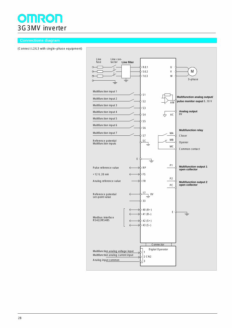
Connections diagram
(Connect L2/L3 with single--phase equipment)
MA
MB
MC
Closer
Opener
Common contact
Multifunction input 1
Multifunction input 2
Multifunction input 3
Multifunction input 4
Line filter
S1
S2
S3
S4
S5
R/L1M
UVW
3--phase
Multifunction relay
Multifunction input 5
S6Multifunction input 6
RP
FS
FR
Pulse reference value
+12 V, 20 mA
Analog reference value
40 (R+)41 (R--)
42 (S+)43 (S--)
Modbus interfaceRS422/RS485
Linefuse
Line con-tactor
S/L2T/L3
E
E
Multifunction input 7S7
17
33
Reference potentialset--point value
AM
Multifunction analog output/pulse monitor ouput 0..10 V
Analog output0VAC
P1
P2
PC
Multifunction output 1open collector
Multifunction output 2open collector
0V
SCReference potentialMultifunction inputs
12 CN23
Multifunction analog voltage inputMultifunction analog current input
Analog input common
Connector
Digital Operator
3G3MV inverter
29
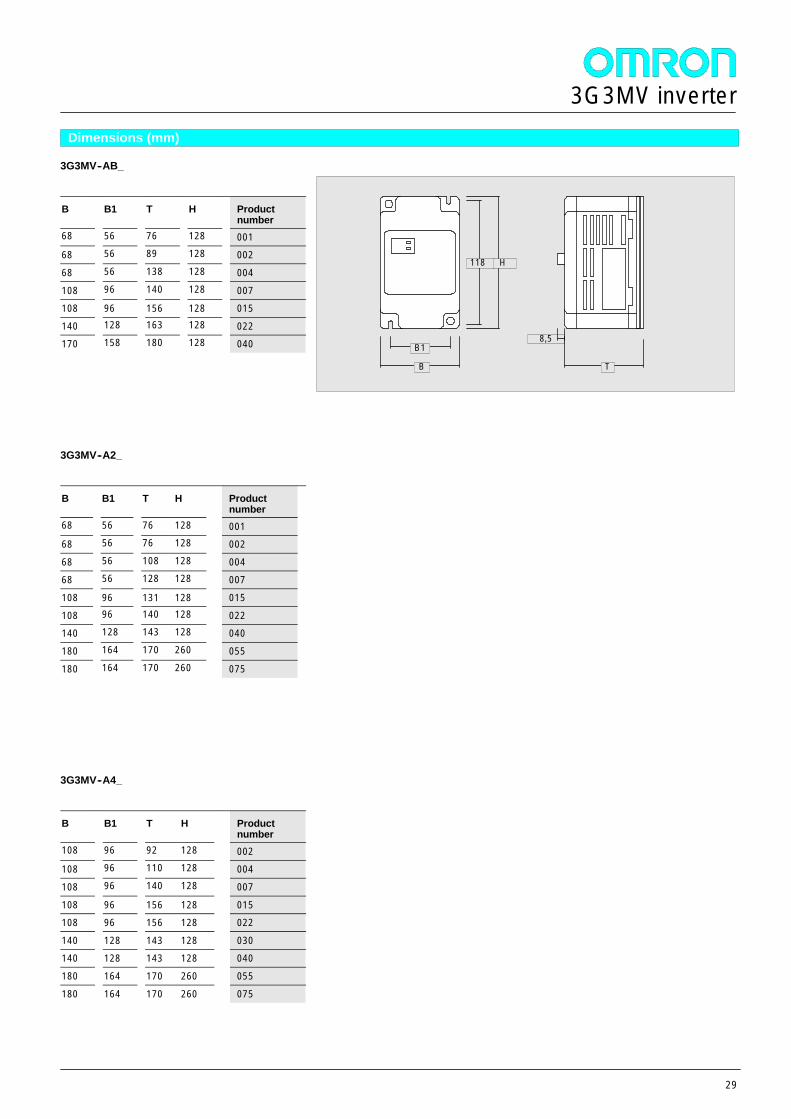
Dimensions (mm)
3G3MV--AB_
B B1 T H Productnumber
68 56 76 128 00168 56 89 128 002
68 56 138 128 004
108 96 140 128 007108 96 156 128 015
140 128 163 128 022170 158 180 128 040
3G3MV--A2_
B B1 T H Productnumber
68 56 76 128 00168 56 76 128 002
68 56 108 128 00468 56 128 128 007
108 96 131 128 015
108 96 140 128 022140 128 143 128 040
180 164 170 260 055
180 164 170 260 075
3G3MV--A4_
B B1 T H Productnumber
108 96 92 128 002108 96 110 128 004
108 96 140 128 007
108 96 156 128 015108 96 156 128 022
140 128 143 128 030140 128 143 128 040
180 164 170 260 055
180 164 170 260 075
8,5
B
118
B1
H
T
3G3MV inverter
30
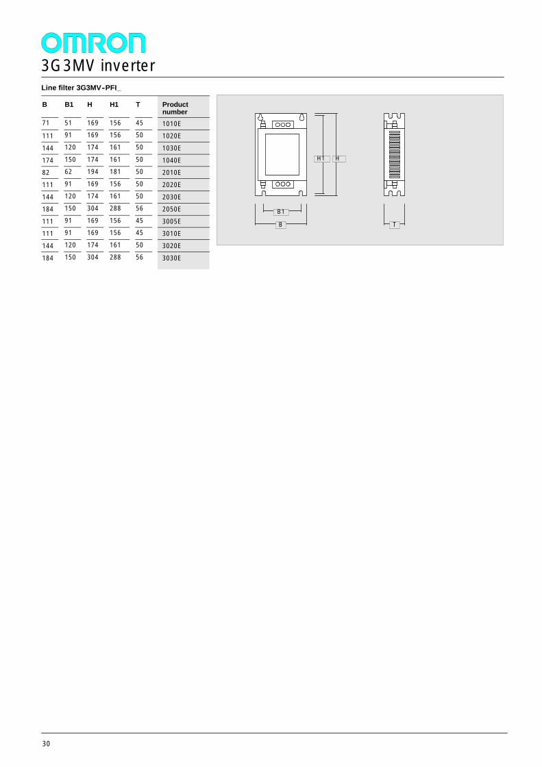
Line filter 3G3MV--PFI_
B B1 H H1 T Productnumber
71 51 169 156 45 1010E111 91 169 156 50 1020E
144 120 174 161 50 1030E
174 150 174 161 50 1040E82 62 194 181 50 2010E
111 91 169 156 50 2020E
144 120 174 161 50 2030E184 150 304 288 56 2050E
111 91 169 156 45 3005E111 91 169 156 45 3010E
144 120 174 161 50 3020E
184 150 304 288 56 3030E
B
H1
B1
H
T
3G3MV inverter
31
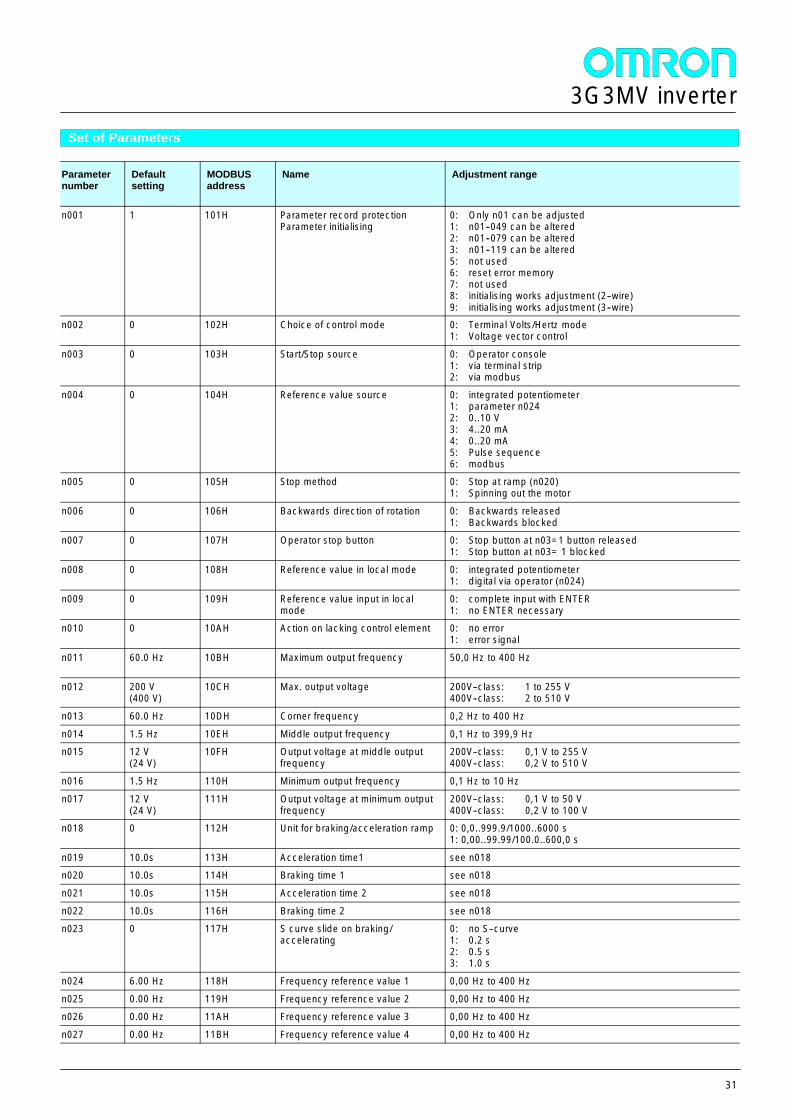
Set of Parameters
Parameternumber
Defaultsetting
MODBUSaddress
Name Adjustment range
n001 1 101H Parameter record protectionParameter initialising
0: Only n01 can be adjusted1: n01--049 can be altered2: n01--079 can be altered3: n01--119 can be altered5: not used6: reset error memory7: not used8: initialising works adjustment (2--wire)9: initialising works adjustment (3--wire)
n002 0 102H Choice of control mode 0: Terminal Volts/Hertz mode1: Voltage vector control
n003 0 103H Start/Stop source 0: Operator console1: via terminal strip2: via modbus
n004 0 104H Reference value source 0: integrated potentiometer1: parameter n0242: 0..10 V3: 4..20 mA4: 0..20 mA5: Pulse sequence6: modbus
n005 0 105H Stop method 0: Stop at ramp (n020)1: Spinning out the motor
n006 0 106H Backwards direction of rotation 0: Backwards released1: Backwards blocked
n007 0 107H Operator stop button 0: Stop button at n03=1 button released1: Stop button at n03= 1 blocked
n008 0 108H Reference value in local mode 0: integrated potentiometer1: digital via operator (n024)
n009 0 109H Reference value input in localmode
0: complete input with ENTER1: no ENTER necessary
n010 0 10AH Action on lacking control element 0: no error1: error signal
n011 60.0 Hz 10BH Maximum output frequency 50,0 Hz to 400 Hz
n012 200 V(400 V)
10CH Max. output voltage 200V--class: 1 to 255 V400V--class: 2 to 510 V
n013 60.0 Hz 10DH Corner frequency 0,2 Hz to 400 Hz
n014 1.5 Hz 10EH Middle output frequency 0,1 Hz to 399,9 Hzn015 12 V
(24 V)10FH Output voltage at middle output
frequency200V--class: 0,1 V to 255 V400V--class: 0,2 V to 510 V
n016 1.5 Hz 110H Minimum output frequency 0,1 Hz to 10 Hz
n017 12 V(24 V)
111H Output voltage at minimum outputfrequency
200V--class: 0,1 V to 50 V400V--class: 0,2 V to 100 V
n018 0 112H Unit for braking/acceleration ramp 0: 0,0..999.9/1000..6000 s1: 0,00..99.99/100.0..600,0 s
n019 10.0s 113H Acceleration time1 see n018n020 10.0s 114H Braking time 1 see n018
n021 10.0s 115H Acceleration time 2 see n018
n022 10.0s 116H Braking time 2 see n018n023 0 117H S curve slide on braking/
accelerating0: no S--curve1: 0.2 s2: 0.5 s3: 1.0 s
n024 6.00 Hz 118H Frequency reference value 1 0,00 Hz to 400 Hz
n025 0.00 Hz 119H Frequency reference value 2 0,00 Hz to 400 Hzn026 0.00 Hz 11AH Frequency reference value 3 0,00 Hz to 400 Hz
n027 0.00 Hz 11BH Frequency reference value 4 0,00 Hz to 400 Hz
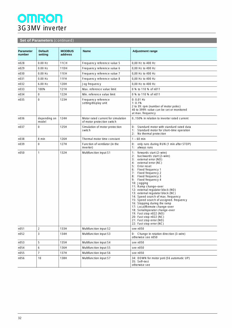
3G3MV inverter
32
Set of Parameters (continued)
Parameternumber
Defaultsetting
MODBUSaddress
Name Adjustment range
n028 0.00 Hz 11CH Frequency reference value 5 0,00 Hz to 400 Hzn029 0.00 Hz 11DH Frequency reference value 6 0,00 Hz to 400 Hz
n030 0.00 Hz 11EH Frequency reference value 7 0,00 Hz to 400 Hzn031 0.00 Hz 11FH Frequency reference value 8 0,00 Hz to 400 Hz
n032 6.00 Hz 120H Jog frequency 0,00 Hz to 400 Hz
n033 100% 121H Max. reference value limit 0 % to 110 % of n011n034 0 122H Min. reference value limit 0 % to 110 % of n011
n035 0 123H Frequency referencesetting/display unit
0: 0.01 Hz1: 0.1%2 to 39: rpm (number of motor poles)40 to 3999: value can be set or monitoredat max. frequency
n036 depending onmodel
124H Motor rated current for simulationof motor protection switch
0..150% in relation to inverter rated current
n037 0 125H Simulation of motor protectionswitch
0: Standard motor with standard rated data1: Standard motor for short--time operation2: No thermal protection
n038 8 min 126H Thermal motor time constant 1 -- 60 minn039 0 127H Function of ventilator (in the
inverter)0: only runs during RUN (1 min after STOP)1: always runs
n050 1 132H Multifunction input S1 1: forwards start (2--wire)2: backwards start (2--wire)3: external error (NO)4: external error (NC)5: Error reset6: Fixed frequency 17: Fixed frequency 28: Fixed frequency 39: Fixed frequency 410: Jogging11: Ramp change--over12: external regulator block (NO)13: external regulator block (NC)14: Speed search of max. frequency15: Speed search of assigned. frequency16: Stopping during the ramp17: Local/Remote change--over18: Serial/operator change--over19: Fast stop n022 (NO)20: Fast stop n022 (NC)21: Fast stop error (NO)22: Fast stop error (NC)
n051 2 133H Multifunction input S2 see n050n052 3 134H Multifunction input S3 0: Change in rotation direction (3--wire)
otherwise see n050
n053 5 135H Multifunction input S4 see n050
n054 6 136H Multifunction input S5 see n050n055 7 137H Multifunction input S6 see n050
n056 10 138H Multifunction input S7 34: DOWN for motor poti (S6 automatic UP)35: Self--testotherwise see
3G3MV inverter
33
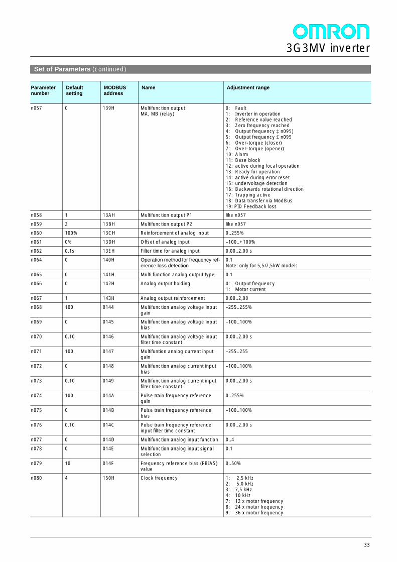
Set of Parameters (continued)
Parameternumber
Defaultsetting
MODBUSaddress
Name Adjustment range
n057 0 139H Multifunction outputMA, MB (relay)
0: Fault1: Inverter in operation2: Reference value reached3: Zero frequency reached4: Output frequency ³ n095)5: Output frequency £n0956: Over--torque (closer)7: Over--torque (opener)10: Alarm11: Base block12: active during local operation13: Ready for operation14: active during error reset15: undervoltage detection16: Backwards rotational direction17: Trapping active18: Data transfer via ModBus19: PID Feedback loss
n058 1 13AH Multifunction output P1 like n057
n059 2 13BH Multifunction output P2 like n057n060 100% 13CH Reinforcement of analog input 0..255%
n061 0% 13DH Offset of analog input --100..+100%
n062 0.1s 13EH Filter time for analog input 0,00..2.00 sn064 0 140H Operation method for frequency ref-
erence loss detection0.1Note: only for 5,5/7,5kW models
n065 0 141H Multi function analog output type 0.1
n066 0 142H Analog output holding 0: Output frequency1: Motor current
n067 1 143H Analog output reinforcement 0,00..2,00
n068 100 0144 Multifunction analog voltage inputgain
--255..255%
n069 0 0145 Multifunction analog voltage inputbias
--100..100%
n070 0.10 0146 Multifunction analog voltage inputfilter time constant
0.00..2.00 s
n071 100 0147 Multifuntion analog current inputgain
--255..255
n072 0 0148 Multifunction analog current inputbias
--100..100%
n073 0.10 0149 Multifunction analog current inputfilter time constant
0.00..2.00 s
n074 100 014A Pulse train frequency referencegain
0..255%
n075 0 014B Pulse train frequency referencebias
--100..100%
n076 0.10 014C Pulse train frequency referenceinput filter time constant
0.00..2.00 s
n077 0 014D Multifunction analog input function 0..4
n078 0 014E Multifunction analog input signalselection
0.1
n079 10 014F Frequency reference bias (FBIAS)value
0..50%
n080 4 150H Clock frequency 1: 2,5 kHz2: 5,0 kHz3: 7,5 kHz4: 10 kHz7: 12 x motor frequency8: 24 x motor frequency9: 36 x motor frequency
3G3MV inverter
34
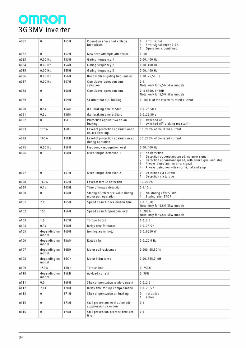
n081 0 151H Operation after short voltagebreakdown
0: Error signal1: Error signal after >0,5 s2: Operation is continued
n082 0 152H New start attempts after error 0..10
n083 0.00 Hz 153H Gating frequency 1 0,00..400 Hzn084 0.00 Hz 154H Gating frequency 2 0,00..400 Hz
n085 0.00 Hz 155H Gating frequency 3 0,00..400 Hz
n086 0.00 Hz 156H Bandwidth of gating frequencies 0,00..25,50 Hzn087 0.00 Hz 157H Cumulative operation time
selection0.1Note: only for 5,5/7,5kW models
n088 0 158H Cumulative operation time 0 to 6550, 1=10HNote: only for 5,5/7,5kW models
n089 0 159H SCurrent for d.c. braking 0..100% of the inverter’s rated current
n090 0.5s 15AH d.c. braking time at Stop 0,0..25,50 s
n091 0.5s 15BH d.c. braking time at Start 0,0..25,50 sn092 0 15CH Protection against sweep on
braking0: switched on1: switched off (braking resistor!!)
n093 170% 15DH Level of protection against sweepon accelerating
30..200% of the rated current
n094 160% 15EH Level of protection against sweepduring operation
30..200% of the rated current
n095 0.00 Hz 15FH Frequency recognition level 0,00..400 Hz
n096 0 160H Over--torque detection 1 0: no detection1: Detection at constant speed, no error signal2: Detection at constant speed, with error signal and stop3: Always detection, no error signal4: Always detection with error signal and stop
n097 0 161H Over--torque detection 2 0: Detection via current1: Detection via torque
n098 160% 162H Level of torque detection 30..200%
n099 0.1s 163H Time of torque detection 0,1.10 sn100 0 164H Storing of reference value during
motor poti operation0: No storing after STOP1: Storing after STOP
n101 2.0 165H Speed search deceleration time 0,0..10,0sNote: only for 5,5/7,5kW models
n102 150 166H Speed search operation level 0..200%Note: only for 5,5/7,5kW models
n103 1.0 167H Torque boost 0,0..2.5
n104 0.3s 168H Delay time for boost 0,0..25.5 s
n105 depending onmodel
169H Iron losses in motor 0,0..6550 W
n106 depending onmodel
16AH Rated slip 0,0..20.0 Hz
n107 depending onmodel
16BH Motor coil resistance 0,000..65,50 W
n108 depending onmodel
16CH Motor inductance 0,00..655,0 mH
n109 150% 16DH Torque limit 0..250%
n110 depending onmodel
16EH no--load current 0..99%
n111 0.0 16FH Slip compensation reinforcement 0,0..2,5
n112 2.0s 170H Delay time for slip compensation 0,0..25,5 s
n113 0 171H Slip compensation on braking 0: not active1: active
n115 0 173H Stall prevention level automaticsuppression selection
0.1
n116 0 174H Stall prevention acc/dec time set-ting
0.1
3G3MV inverter
35
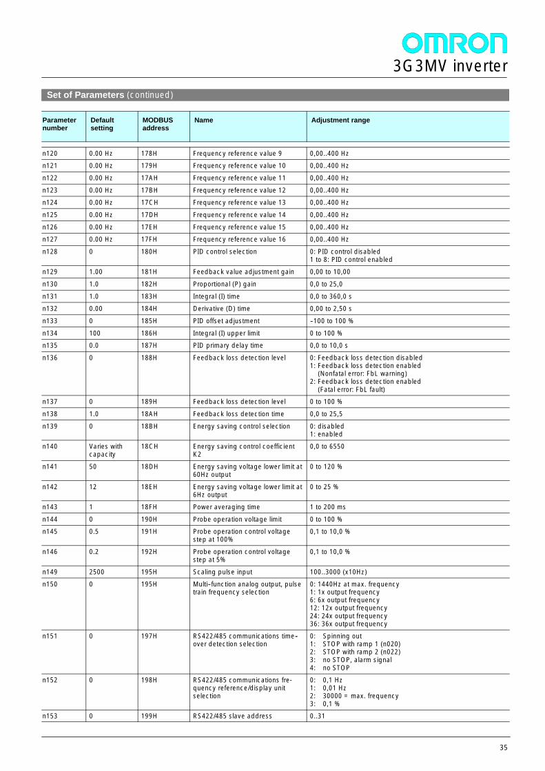
Set of Parameters (continued)
Parameternumber
Defaultsetting
MODBUSaddress
Name Adjustment range
n120 0.00 Hz 178H Frequency reference value 9 0,00..400 Hzn121 0.00 Hz 179H Frequency reference value 10 0,00..400 Hz
n122 0.00 Hz 17AH Frequency reference value 11 0,00..400 Hz
n123 0.00 Hz 17BH Frequency reference value 12 0,00..400 Hzn124 0.00 Hz 17CH Frequency reference value 13 0,00..400 Hz
n125 0.00 Hz 17DH Frequency reference value 14 0,00..400 Hz
n126 0.00 Hz 17EH Frequency reference value 15 0,00..400 Hzn127 0.00 Hz 17FH Frequency reference value 16 0,00..400 Hz
n128 0 180H PID control selection 0: PID control disabled1 to 8: PID control enabled
n129 1.00 181H Feedback value adjustment gain 0,00 to 10,00
n130 1.0 182H Proportional (P) gain 0,0 to 25,0
n131 1.0 183H Integral (I) time 0,0 to 360,0 sn132 0.00 184H Derivative (D) time 0,00 to 2,50 s
n133 0 185H PID offset adjustment --100 to 100 %
n134 100 186H Integral (I) upper limit 0 to 100 %n135 0.0 187H PID primary delay time 0,0 to 10,0 s
n136 0 188H Feedback loss detection level 0: Feedback loss detection disabled1: Feedback loss detection enabled
(Nonfatal error: FbL warning)2: Feedback loss detection enabled
(Fatal error: FbL fault)n137 0 189H Feedback loss detection level 0 to 100 %
n138 1.0 18AH Feedback loss detection time 0,0 to 25,5
n139 0 18BH Energy saving control selection 0: disabled1: enabled
n140 Varies withcapacity
18CH Energy saving control coefficientK2
0,0 to 6550
n141 50 18DH Energy saving voltage lower limit at60Hz output
0 to 120 %
n142 12 18EH Energy saving voltage lower limit at6Hz output
0 to 25 %
n143 1 18FH Power averaging time 1 to 200 ms
n144 0 190H Probe operation voltage limit 0 to 100 %n145 0.5 191H Probe operation control voltage
step at 100%0,1 to 10,0 %
n146 0.2 192H Probe operation control voltagestep at 5%
0,1 to 10,0 %
n149 2500 195H Scaling pulse input 100..3000 (x10Hz)n150 0 195H Multi--function analog output, pulse
train frequency selection0: 1440Hz at max. frequency1: 1x output frequency6: 6x output frequency12: 12x output frequency24: 24x output frequency36: 36x output frequency
n151 0 197H RS422/485 communications time--over detection selection
0: Spinning out1: STOP with ramp 1 (n020)2: STOP with ramp 2 (n022)3: no STOP, alarm signal4: no STOP
n152 0 198H RS422/485 communications fre-quency reference/display unitselection
0: 0,1 Hz1: 0,01 Hz2: 30000 = max. frequency3: 0,1 %
n153 0 199H RS422/485 slave address 0..31
3G3MV inverter
36
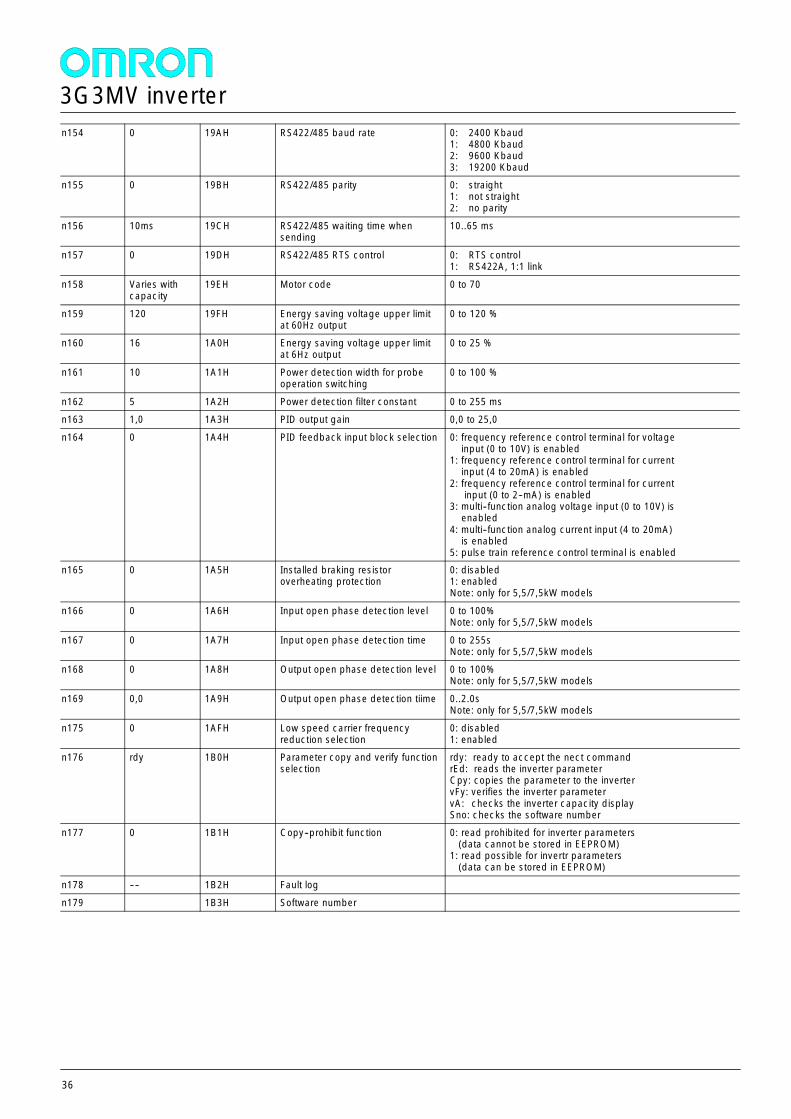
n154 0 19AH RS422/485 baud rate 0: 2400 Kbaud1: 4800 Kbaud2: 9600 Kbaud3: 19200 Kbaud
n155 0 19BH RS422/485 parity 0: straight1: not straight2: no parity
n156 10ms 19CH RS422/485 waiting time whensending
10..65 ms
n157 0 19DH RS422/485 RTS control 0: RTS control1: RS422A, 1:1 link
n158 Varies withcapacity
19EH Motor code 0 to 70
n159 120 19FH Energy saving voltage upper limitat 60Hz output
0 to 120 %
n160 16 1A0H Energy saving voltage upper limitat 6Hz output
0 to 25 %
n161 10 1A1H Power detection width for probeoperation switching
0 to 100 %
n162 5 1A2H Power detection filter constant 0 to 255 msn163 1,0 1A3H PID output gain 0,0 to 25,0
n164 0 1A4H PID feedback input block selection 0: frequency reference control terminal for voltageinput (0 to 10V) is enabled
1: frequency reference control terminal for currentinput (4 to 20mA) is enabled
2: frequency reference control terminal for currentinput (0 to 2--mA) is enabled
3: multi--function analog voltage input (0 to 10V) isenabled
4: multi--function analog current input (4 to 20mA)is enabled
5: pulse train reference control terminal is enabledn165 0 1A5H Installed braking resistor
overheating protection0: disabled1: enabledNote: only for 5,5/7,5kW models
n166 0 1A6H Input open phase detection level 0 to 100%Note: only for 5,5/7,5kW models
n167 0 1A7H Input open phase detection time 0 to 255sNote: only for 5,5/7,5kW models
n168 0 1A8H Output open phase detection level 0 to 100%Note: only for 5,5/7,5kW models
n169 0,0 1A9H Output open phase detection tiime 0..2.0sNote: only for 5,5/7,5kW models
n175 0 1AFH Low speed carrier frequencyreduction selection
0: disabled1: enabled
n176 rdy 1B0H Parameter copy and verify functionselection
rdy: ready to accept the nect commandrEd: reads the inverter parameterCpy: copies the parameter to the invertervFy: verifies the inverter parametervA: checks the inverter capacity displaySno: checks the software number
n177 0 1B1H Copy--prohibit function 0: read prohibited for inverter parameters(data cannot be stored in EEPROM)
1: read possible for invertr parameters(data can be stored in EEPROM)
n178 ---- 1B2H Fault log
n179 1B3H Software number
3G3MV inverter
37
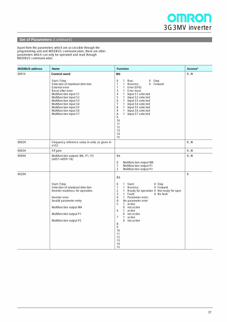
Set of Parameters (continued)
Apart from the parameters which are accessible through theprogramming unit and MODBUS communication, there are otherparameters which can only be operated and read throughMODBUS communication.
MODBUS address Name Function Access*
0001h Control word
Start / StopSelection of rotational directionExternal errorReset after errorMultifunction input S1Multifunction input S2Multifunction input S3Multifunction input S4Multifunction input S5Multifunction input S6Multifunction input S7
Bit
0 1 Run; 0 Stop1 1 Reverse; 0 Forward1 1 Error (EF0)3 1 Error reset4 1 Input S1 selected5 1 Input S2 selected6 1 Input S3 selected7 1 Input S4 selected8 1 Input S5 selected9 1 Input S6 selectedA 1 Input S7 selected9101112131415
R, W
0002H Frequency reference value in units as given inn152
R, W
0003H V/f gain R, W
0009H Multifunction outputs MA, P1, P2(n057--n059=18)
Bit
0 Multifunction output MA1 Multifunction output P12 Multifunction output P2
R, W
0020H
Start / StopSelection of rotational directionInverter readiness for operation
Inverter errorInvalid parameter entry
Multifunction output MA
Multifunction output P1
Multifunction output P2
Bit
0 1 Start; 0 Stop1 1 Reverse; 0 Forward2 1 Ready for operation 0 Not ready for oper.3 1 Fault; 0 No fault4 1 Parameter error;0: No parameter error5 1 active
0 not active6 1 active
0 not active7 1 active
0 not active89101112131415
R
3G3MV inverter
38
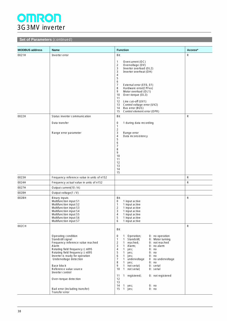
Set of Parameters (continued)
MODBUS address Name Function Access*
0021H Inverter error Bit
1 Overcurrent (OC)2 Overvoltage (OV)3 Inverter overload (OL2)3 Inverter overheat (OH)4567 External error (EF0, EF)8 Hardware error(CPFxx)9 Motor overload (OL1)10 Over--torque (OL3)1112 Line cut--off (UV1)13 Control voltage error (UV2)14 Bus error (BUS)15 Control element error (OPR)
R
0022H Status inverter communication
Data transfer
Range error parameter
Bit
0 1 during data recording123 Range error4 Data inconsistency56789101112131415
R
0023H Frequency reference value in units of n152 R0024H Frequency actual value in units of n152 R
0027H Output current(10 / A)
0028H Output voltage(1 / V)002BH Binary inputs
Multifunction input S1Multifunction input S2Multifunction input S3Multifunction input S4Multifunction input S5Multifunction input S6Multifunction input S7
Bit0 1 input active1 1 input active2 1 input active3 1 input active4 1 input active5 1 input active6 1 input active
R
002CH
Operating conditionStandstill signalFrequency reference value reachedAlarmRotating field frequency £n095Rotating field frequency ³ n095Inverter is ready for operationUndervoltage detection
Base blockReference value sourceInverter control
Over--torque detection
Bad error (including transfer)Transfer error
Bit
0 1 Operation; 0: no operation1 1 Standstill; 0: Motor turning2 1 reached; 0: not reached3 1 Alarm; 0: no alarm4 1 yes; 0: no5 1 yes; 0: no6 1 yes; 0: no7 1 undervoltage 0 no undervoltage8 1 yes; 0: no9 1 not serial; 0: serial10 1 not serial; 0: serial
11 1 registered; 0: not registered121314 1 yes; 0: no15 1 yes; 0: no
R
3G3MV inverter
39
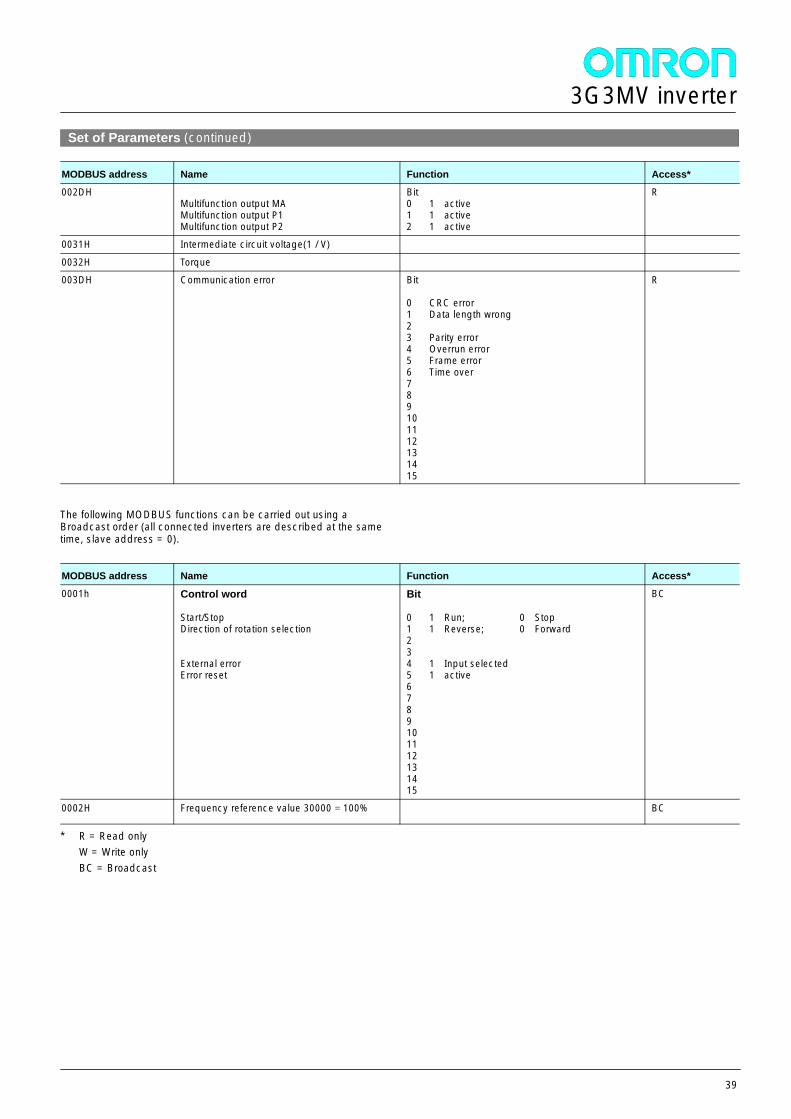
Set of Parameters (continued)
MODBUS address Name Function Access*
002DHMultifunction output MAMultifunction output P1Multifunction output P2
Bit0 1 active1 1 active2 1 active
R
0031H Intermediate circuit voltage(1 / V)
0032H Torque003DH Communication error Bit
0 CRC error1 Data length wrong23 Parity error4 Overrun error5 Frame error6 Time over789101112131415
R
The following MODBUS functions can be carried out using aBroadcast order (all connected inverters are described at the sametime, slave address = 0).
MODBUS address Name Function Access*
0001h Control word
Start/StopDirection of rotation selection
External errorError reset
Bit
0 1 Run; 0 Stop1 1 Reverse; 0 Forward234 1 Input selected5 1 active6789101112131415
BC
0002H Frequency reference value 30000 = 100% BC
* R = Read onlyW = Write onlyBC = Broadcast

3G3MV inverter
40
3G3HV inverter
41
General
The 3G3HV is designed in particular for applications with quadraticpower requirement. Pumps and ventilators are always operated withthe highest efficiency by means of a self-adapting energy savingfunction.
Features:-- power range: 0,4...300 kW-- PID controller-- self-adapting energy saving function-- NPN or PNP digital inputs-- analog frequency default: 0...10 VDC or 4...20 mA-- high continuous output current-- low noise thanks to high carrier frequency (adjustable to 15 kHz)-- built-in programming unit-- MODBUS interface RS-422/-485-- built-in DC reactor above 15 kW-- 12 pulse rectifier above 15 kW
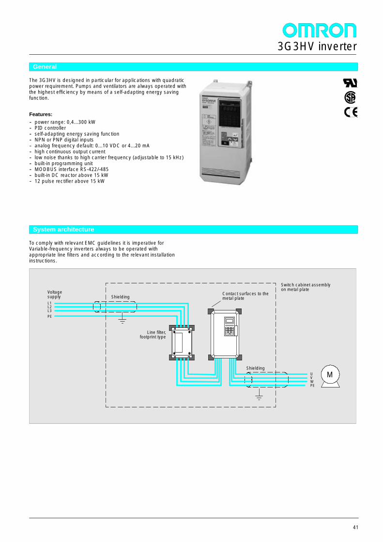
System architecture
To comply with relevant EMC guidelines it is imperative forVariable-frequency inverters always to be operated withappropriate line filters and according to the relevant installationinstructions.
L1L2L3PE
Line filter,footprint type
UVWPE
Shielding
Switch cabinet assemblyon metal plateVoltage
supply
M
ShieldingContact surfaces to themetal plate
3G3HV inverter
42
Product overview
Inverter: 200 V Class: Model 3G3HV--AB_--CE
3G3HV--A B004 B007 B015 B022 B037Maximum allowed motor output kW 0,55 1,1 1,5 2,2 3,7
Output data Inverter performance kVA 1,2 2,3 3,0 4,2 6,7Output data
Output rated current A 3,2 6 8 11 17,5
Inverter: 400 V Class: Model 3G3HV--A4_--CE
3G3HV--A 4004 4007 4015 4022 4037 4040 4055 4075 4110 4150Maximum allowed motor output kW 0,55 1,1 1,5 2,2 3,7 4,0 5,5 7,5 11 15
Output data Inverter performance kVA 1,4 2,6 3,7 4,7 6,1 8,4 11 14 21 26Output data
Output rated current A 1,8 3,4 4,8 6,2 8 11 14 18 27 34
3G3HV--B 4185 4220 4300 4370 4450 4550 4750 411K 416KMaximum allowed motor output kW 18,5 22 30 37 45 55 75 110 160
Output data Inverter performance kVA 31 40 50 61 73 98 130 170 230Output data
Output rated current A 41 52 65 80 96 128 165 224 302
3G3HV--B 418K 422K 430KMaximum allowed motor output kW 185 220 300
Output data Inverter performance kVA 260 340 460Output data
Output rated current A 380 506 675
AccessoriesLine filter
Line filter Rated voltage Line filter Current*3G3HV--AB004--CE 1 x 230 VAC 3G3HV--PFI1010--E 10 A
3G3HV--AB007--CE and 3G3HV--AB015--CE 1 x 230 VAC 3G3HV--PFI1020--E 20 A3G3HV--AB022--CE and 3G3HV--AB037--CE 1 x 230 VAC 3G3HV--PFI1040--E 40 A
3G3HV--A4004--CE and 3G3HV--A4007--CE 3 x 400 VAC 3G3FV--PFI4012--E* 12 A
3G3HV--A4015--CE 3 x 400 VAC 3G3FV--PFI4012--E* 12 A3G3HV--A4022--CE 3 x 400 VAC 3G3FV--PFI4012--E* 12 A
3G3HV--A4037--CE and 3G3HV--A4040--CE 3 x 400 VAC 3G3FV--PFI4012--E* 12 A
3G3HV--A4055--CE 3 x 400 VAC 3G3FV--PFI4025--E* 25 A3G3HV--A4075--CE 3 x 400 VAC 3G3FV--PFI4025--E* 25 A
3G3HV--A4110--CE 3 x 400 VAC 3G3FV--PFI4040--E* 40 A3G3HV--A4150--CE 3 x 400 VAC 3G3FV--PFI4040--E* 40 A
3G3HV--B4185--CE and 3G3HV--B4220--CE 3 x 400 VAC 3G3FV--PFI4060--E 60 A
3G3HV--B4300--CE and 3G3HV--B4370--CE 3 x 400 VAC 3G3FV--PFI4100--E 100 A3G3HV--B4450--CE 3 x 400 VAC 3G3FV--PFI4120--E 120 A
3G3HV--B4550--CE 3 x 400 VAC 3G3FV--PFI4150--E 150 A3G3HV--B4750--CE 3 x 400 VAC 3G3FV--PFI4180--E 180 A
3G3HV--B411K--CE 3 x 400 VAC 3G3FV--PFI4280--E 280 A
3G3HV--B418K--CUE 3 x 400 VAC 3G3FV--PFI4450--E 450 A3G3HV--B418K--CUE 3 x 400 VAC 3G3FV--PFI4450--E 450 A
3G3HV--B422K--CUE 3 x 400 VAC 3G3FV--PFI4600--E 600 A
3G3HV--B430K--CUE 3 x 400 VAC 3G3FV--PFI4900--E 900 A
* footprint type
3G3HV inverter
43
Accessories (continued)
Brake choppers, braking resistors
Inverter Rated voltage Brake chopper Number Braking resistors Number Specificationfor each unit
for inverter, single-phase 230 V
3G3HV--AB004--CE 1 x 230 VAC built-in -- 3G3IV--PERF150W--J620 1 62 W , 150 W3G3HV--AB007--CE 1 x 230 VAC built-in -- 3G3IV--PERF150W--J620 1 62 W , 150 W
3G3HV--AB015--CE 1 x 230 VAC built-in -- 3G3IV--PERF150W--J620 1 62 W , 150 W
3G3HV--AB022--CE 1 x 230 VAC built-in -- 3G3IV--PERF150W--J620 1 62 W , 150 W3G3HV--AB037--CE 1 x 230 VAC built-in 3G3IV--PERF150W--J620 1 62 W , 150 W
for inverter, three-phase 400 V
3G3HV--A4004--CE 3 x 400 VAC built-in -- 3G3IV--PERF150W--J101 1 100 W , 150 W3G3HV--A4007--CE 3 x 400 VAC built-in -- 3G3IV--PERF150W--J101 1 100 W , 150 W
3G3HV--A4015--CE 3 x 400 VAC built-in -- 3G3IV--PERF150W--J101 1 100 W , 150 W
3G3HV--A4022--CE 3 x 400 VAC built-in -- 3G3IV--PERF250W--J680T 1 68 W , 250 W3G3HV--A4037--CE 3 x 400 VAC built-in -- 3G3IV--PERF500W--J360T 1 36 W , 500 W
3G3HV--A4040--CE 3 x 400 VAC built-in -- 3G3IV--PERF500W--J360T 1 36 W , 500 W
3G3HV--A4055--CE 3 x 400 VAC built-in -- 3G3IV--PERF500W--J360T 1 36 W , 500 W3G3HV--A4075--CE 3 x 400 VAC built-in -- 3G3IV--PERF101W--J360T 1 36 W , 1000 W
3G3HV--A4110--CE 3 x 400 VAC built-in -- 3G3IV--PERF151W--J200T 1 20 W , 1500 W3G3HV--A4150--CE 3 x 400 VAC built-in -- 3G3IV--PERF151W--J200T 1 20 W , 1500 W
Other
Description Cable length Product numberAdapter for front panel installation, fixed mounting of console -- 3G3FV--PDACT--AD
Adapter for front panel installation, removable console -- 3G3FV--PDACT--BDExtension cable to programming console 1 m 3G3FV--PCN125
Extension cable to programming console 3 m 3G3FV--PCN325Ferrite rings for output, D = 21 to 58 mm -- 3G3IV--PFO--OC1--OC4
3G3HV inverter
44
Programming accessories
PC programming Description Cable length Product numberPC programmingProgramming software under WINDOWS -- SYSDRIVE Configurator
Connecting cable 2 m 3G3FV--PCNDW225N
Technical data
Type 3G3HV--A4_--CE 3G3HV--B4_--(--CE) 3G3HV--AB_--CE
Output data Max. output voltage three-phase: 380/400/415/440/460 V (prop. to input volt.) three-phase: 200-240 V(prop. to input volt.)
Output frequency 0,1 Hz to 400 Hz
Supply Rated input voltage andfrequency
three-phase: 380/400/415/440/460 V, 50/60 Hz three-phase: 200-240 V,50/60 Hz
Allowed voltage variation +10%, --15%
Allowed frequency variation ±5%
Control functions Type of control sinusoidal pulse width modulation (PWM)Control functions
Output frequency range 0,1-400 Hz
Frequency precision digital default: ±0,01% (--10°C to +40°C)analog default: ±0,1% (25°C ±10°C)
Frequency resolution digital default: 0,1 Hzanalog default: 0,05 Hz, 50 Hz (10 Bits)
Output frequency resolution 0.01 Hz
Overload capacity 150% of the output ratedcurrent for 1 minute
120% of the output rated current for 1 minute150% for 12 s
Frequency reference value signal 0-10 VDC (20 kW ), 4-20 mA (250 W )
Acceleration/deceleration 0,0 bis 3600 s (can be programmed independently)
Braking torque about 20% (with brakingresistor up to 125%)
about 20%
U/f characteristics 15 already programmed and one freely programmable characteristic
Protectivefunctions
Protection against motoroverload
thermo-electronic protection against overloadfunctions
Instantaneous overcurrent stops at approx. 200% ofrated output current
stops at approx. 180% of rated output current
Overload at 150% of the output ratedcurrent the motor coasts tostop after 1 minute
at 120% of the output rated current the motor coasts tostop after 1 minute
Overvoltage stops when main circuit DC voltage is approx. 820 V
Undervoltage stops when main circuit DC voltage is approx. 380 V (400 V model)
Supply voltage failure after failure of longer than 15 ms the output switches off. After the return of voltageoperation can be automatically continued.
Cooling fin overheating protection by thermistor
Stall prevention stall prevention during the acceleration and braking phase, and also during constant fre-quency operation
Earth fault via electronic circuit
Charge indicator the charge indicator lights up until the intermediate circuit voltage falls under 50 V
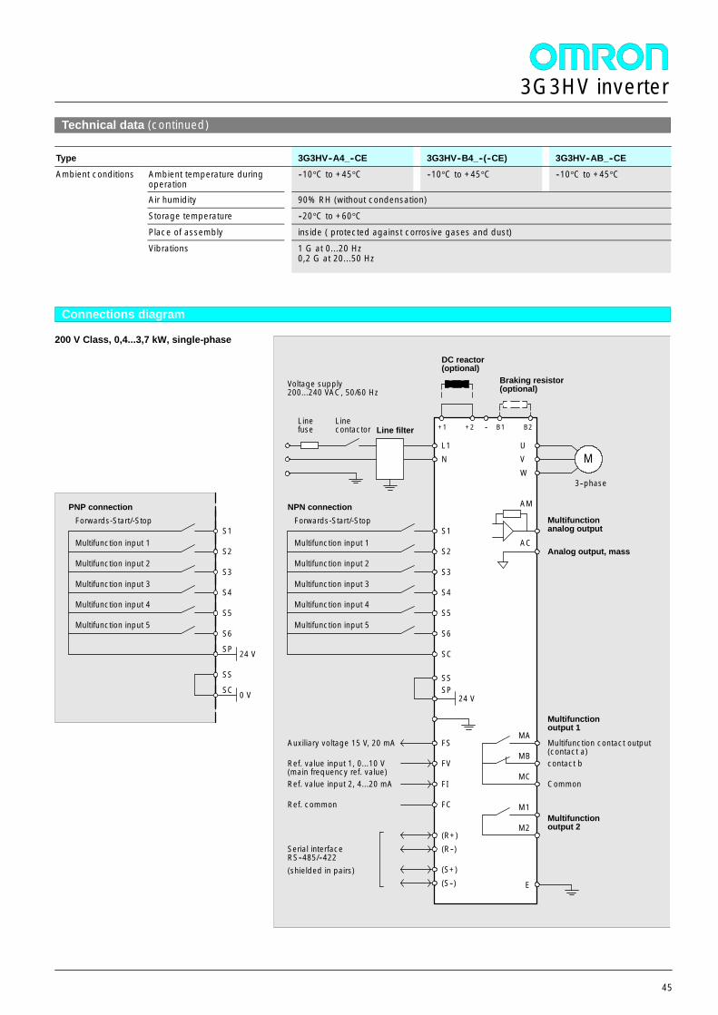
3G3HV inverter
45
Technical data (continued)
Type 3G3HV--A4_--CE 3G3HV--B4_--(--CE) 3G3HV--AB_--CE
Ambient conditions Ambient temperature duringoperation
--10°C to +45°C --10°C to +45°C --10°C to +45°C
Air humidity 90% RH (without condensation)
Storage temperature --20°C to +60°C
Place of assembly inside ( protected against corrosive gases and dust)
Vibrations 1 G at 0...20 Hz0,2 G at 20...50 Hz
Connections diagram
200 V Class, 0,4...3,7 kW, single-phase
MA
MB
MC
Multifunction contact output(contact a)contact b
Common
Multifunctionoutput 1
Forwards-Start/-Stop
Multifunction input 1
Multifunction input 2
Multifunction input 3
Line filter
Voltage supply200...240 VAC, 50/60 Hz
S1
S2
S3
S4
S5
L1N
+1
Braking resistor(optional)
MUVW
AM
Multifunctionanalog output
3--phase
M1
M2Multifunctionoutput 2
Multifunction input 4
S6Multifunction input 5
SSSP
24 V
FS
FV
FI
FC
Auxiliary voltage 15 V, 20 mA
Ref. value input 1, 0...10 V(main frequency ref. value)Ref. value input 2, 4...20 mA
Ref. common
(R+)(R--)
(S+)(S--)
Serial interfaceRS--485/--422(shielded in pairs)
+2
DC reactor(optional)
-- B1 B2Linefuse
Linecontactor
Analog output, massAC
Forwards-Start/-Stop
Multifunction input 1
Multifunction input 2
Multifunction input 3
S1
S2
S3
S4
S5Multifunction input 4
S6Multifunction input 5
SP 24 V SC
NPN connectionPNP connection
SS
SC 0 V
E
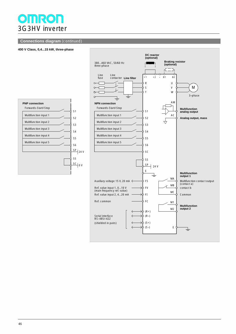
3G3HV inverter
46
Connections diagram (continued)
400 V Class, 0,4...15 kW, three-phase
MA
MB
MC
Multifunction contact output(contact a)contact b
Common
Multifunctionoutput 1
Forwards-Start/-Stop
Multifunction input 1
Multifunction input 2
Multifunction input 3
Line filter
380...460 VAC, 50/60 Hzthree-phase
S1
S2
S3
S4
S5
R
+1
Braking resistor(optional)
MUVW
AM
Multifunctionanalog output
3--phase
M1
M2Multifunctionoutput 2
Multifunction input 4
S6Multifunction input 5
SC
SS
SP 24 V
FS
FV
FI
FC
Auxiliary voltage 15 V, 20 mA
Ref. value input 1, 0...10 V(main frequency ref. value)Ref. value input 2, 4...20 mA
Ref. common
(R+)(R--)
(S+)(S--)
Serial interfaceRS--485/--422(shielded in pairs)
+2
DC reactor(optional)
-- B1 B2Linefuse
Linecontactor
Analog output, massAC
ST
E
NPN connection
E
Forwards-Start/-Stop
Multifunction input 1
Multifunction input 2
Multifunction input 3
S1
S2
S3
S4
S5Multifunction input 4
S6Multifunction input 5
SP 24 V
PNP connection
SS
SC 0 V
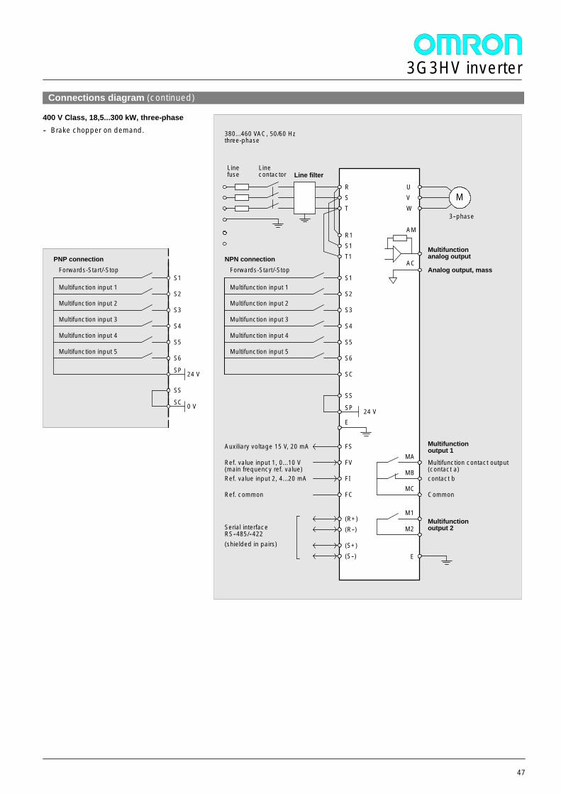
3G3HV inverter
47
Connections diagram (continued)
400 V Class, 18,5...300 kW, three-phase-- Brake chopper on demand.
MA
MB
MC
Multifunction contact output(contact a)contact b
Common
Multifunctionoutput 1
Forwards-Start/-Stop
Multifunction input 1
Multifunction input 2
Multifunction input 3
Line filter
380...460 VAC, 50/60 Hzthree-phase
S1
S2
S3
S4
S5
RM
UVW
AM
Multifunctionanalog output
3--phase
M1
M2Multifunctionoutput 2
Multifunction input 4
S6Multifunction input 5
SC
Linefuse
Linecontactor
Analog output, massAC
ST
R1S1T1
SS
SP 24 V
FS
FV
FI
FC
Auxiliary voltage 15 V, 20 mA
Ref. value input 1, 0...10 V(main frequency ref. value)Ref. value input 2, 4...20 mA
Ref. common
(R+)(R--)
(S+)(S--)
Serial interfaceRS--485/--422(shielded in pairs)
E
NPN connection
E
Forwards-Start/-Stop
Multifunction input 1
Multifunction input 2
Multifunction input 3
S1
S2
S3
S4
S5Multifunction input 4
S6Multifunction input 5
SP 24 V
PNP connection
SS
SC 0 V
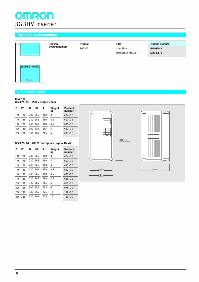
3G3HV inverter
48
Technical documentation
Englishdocumentation
Product Title Product numberEnglishdocumentation 3G3HV User Manual I515--E1--2
SYSDRIVE INVERTER
3G3HV
Installation Manual I520--E1--1
OPERATION MANUALOPERATION MANUAL
Dimensions (mm)
Inverter3G3HV--AB_, 200 V single-phase
B B1 H H1 T Weightkg
Productnumber
140 126 280 266 160 3 004--CE140 126 280 266 180 4,5 007--CE
140 126 280 266 180 4,5 015--CE
200 186 300 285 205 6 022--CE200 186 300 285 205 6 037--CE
3G3HV--A4_, 400 V three-phase, up to 15 kW
B B1 H H1 T Weightkg
Productnumber
140 126 280 266 160 3 004--CE
140 126 280 266 160 3 007--CE
140 126 280 266 180 4 015--CE140 126 280 266 180 4,5 022--CE
140 126 280 266 180 4,5 037--CE140 126 280 266 180 4,5 040--CE
200 186 300 285 205 6 055--CE
200 186 300 285 205 6 075--CE250 236 380 365 225 11 110--CE
250 236 380 365 225 11 150--CE
B
H1
T
H
B1
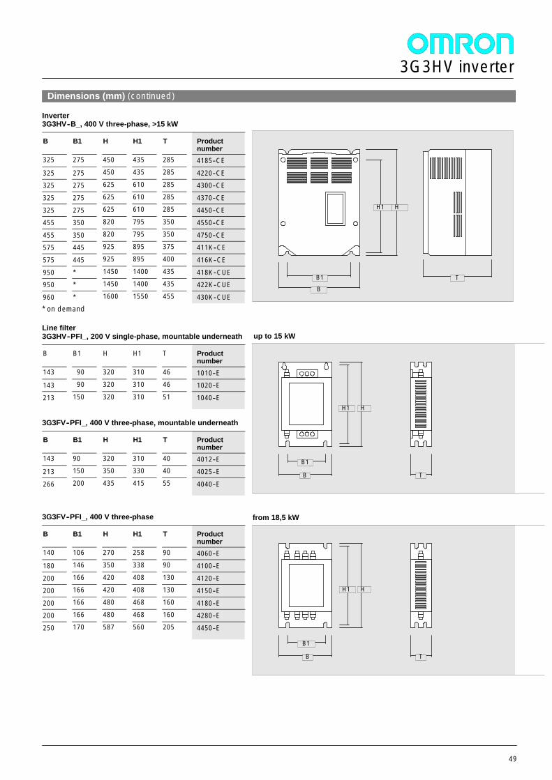
3G3HV inverter
49
Dimensions (mm) (continued)
Inverter3G3HV--B_, 400 V three-phase, >15 kW
B B1 H H1 T Productnumber
325 275 450 435 285 4185--CE
325 275 450 435 285 4220--CE325 275 625 610 285 4300--CE
325 275 625 610 285 4370--CE325 275 625 610 285 4450--CE
455 350 820 795 350 4550--CE
455 350 820 795 350 4750--CE575 445 925 895 375 411K--CE
575 445 925 895 400 416K--CE
950 * 1450 1400 435 418K--CUE950 * 1450 1400 435 422K--CUE
960 * 1600 1550 455 430K--CUE* on demand
Line filter3G3HV--PFI_, 200 V single-phase, mountable underneath
B B1 H H1 T Productnumber
143 90 320 310 46 1010--E143 90 320 310 46 1020--E
213 150 320 310 51 1040--E
3G3FV--PFI_, 400 V three-phase, mountable underneath
B B1 H H1 T Productnumber
143 90 320 310 40 4012--E213 150 350 330 40 4025--E
266 200 435 415 55 4040--E
3G3FV--PFI_, 400 V three-phase
B B1 H H1 T Productnumber
140 106 270 258 90 4060--E
180 146 350 338 90 4100--E
200 166 420 408 130 4120--E200 166 420 408 130 4150--E
200 166 480 468 160 4180--E200 166 480 468 160 4280--E
250 170 587 560 205 4450--E
B
H1
TB1
H
B
H1
B1
H
T
B
H1
B1
H
T
up to 15 kW
from 18,5 kW

3G3HV inverter
50
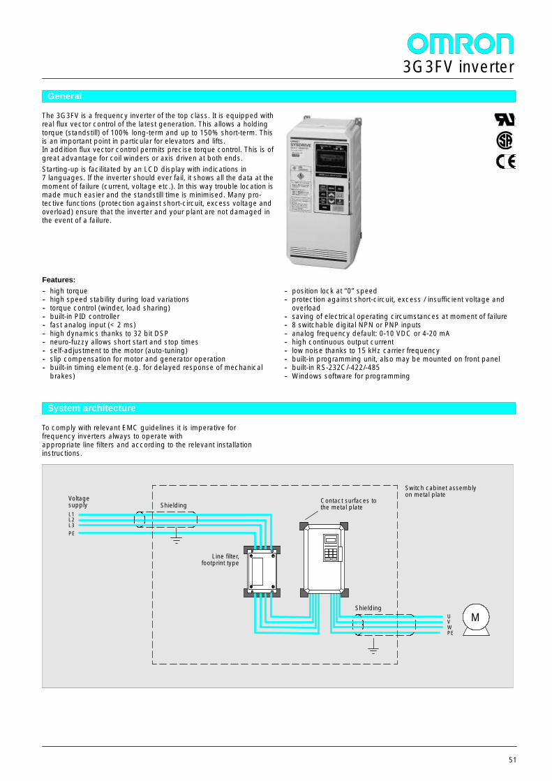
3G3FV inverter
51
General
The 3G3FV is a frequency inverter of the top class. It is equipped withreal flux vector control of the latest generation. This allows a holdingtorque (standstill) of 100% long-term and up to 150% short-term. Thisis an important point in particular for elevators and lifts.In addition flux vector control permits precise torque control. This is ofgreat advantage for coil winders or axis driven at both ends.Starting-up is facilitated by an LCD display with indications in7 languages. If the inverter should ever fail, it shows all the data at themoment of failure (current, voltage etc.). In this way trouble location ismade much easier and the standstill time is minimised. Many pro-tective functions (protection against short-circuit, excess voltage andoverload) ensure that the inverter and your plant are not damaged inthe event of a failure.
Features:-- high torque-- high speed stability during load variations-- torque control (winder, load sharing)-- built-in PID controller-- fast analog input (< 2 ms)-- high dynamics thanks to 32 bit DSP-- neuro-fuzzy allows short start and stop times-- self-adjustment to the motor (auto-tuning)-- slip compensation for motor and generator operation-- built-in timing element (e.g. for delayed response of mechanical
brakes)
-- position lock at “0”speed-- protection against short-circuit, excess / insufficient voltage and
overload-- saving of electrical operating circumstances at moment of failure-- 8 switchable digital NPN or PNP inputs-- analog frequency default: 0-10 VDC or 4-20 mA-- high continuous output current-- low noise thanks to 15 kHz carrier frequency-- built-in programming unit, also may be mounted on front panel-- built-in RS-232C/-422/-485-- Windows software for programming
System architecture
To comply with relevant EMC guidelines it is imperative forfrequency inverters always to operate withappropriate line filters and according to the relevant installationinstructions.
L1L2L3PE
Line filter,footprint type
UVWPE
Shielding
Switch cabinet assemblyon metal plateVoltage
supply
M
ShieldingContact surfaces tothe metal plate
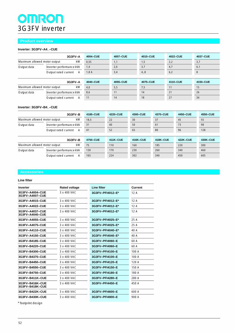
3G3FV inverter
52
Product overview
Inverter: 3G3FV--A4_--CUE
3G3FV--A 4004--CUE 4007--CUE 4015--CUE 4022--CUE 4037--CUE
Maximum allowed motor output kW 0,55 1,1 1,5 2,2 3,7
Output data Inverter performance kVA 1,4 2,6 3,7 4,7 6,1Output data
Output rated current A 1,8 A 3,4 4,.8 6,2 8
3G3FV--A 4040--CUE 4055--CUE 4075--CUE 4110--CUE 4150--CUE
Maximum allowed motor output kW 4,0 5,5 7,5 11 15
Output data Inverter performance kVA 8,6 11 14 21 26Output data
Output rated current A 11 14 18 27 34
Inverter: 3G3FV--B4_--CUE
3G3FV--B 4185--CUE 4220--CUE 4300--CUE 4370--CUE 4450--CUE 4550--CUE
Maximum allowed motor output kW 18,5 22 30 37 45 55
Output data Inverter performance kVA 31 40 50 61 73 98Output data
Output rated current A 41 52 65 80 96 128
3G3FV--B 4750--CUE 411K--CUE 416K--CUE 418K--CUE 422K--CUE 430K--CUE
Maximum allowed motor output kW 75 110 160 185 220 300
Output data Inverter performance kVA 130 170 230 260 340 460Output data
Output rated current A 165 224 302 340 450 605
Accessories
Line filter
Inverter Rated voltage Line filter Current3G3FV--A4004--CUE3G3FV--A4007--CUE
3 x 400 VAC 3G3FV--PFI4012--E* 12 A
3G3FV--A4015--CUE 3 x 400 VAC 3G3FV--PFI4012--E* 12 A
3G3FV--A4022--CUE 3 x 400 VAC 3G3FV--PFI4012--E* 12 A3G3FV--A4037--CUE3G3FV--A4040--CUE
3 x 400 VAC 3G3FV--PFI4012--E* 12 A
3G3FV--A4055--CUE 3 x 400 VAC 3G3FV--PFI4025--E* 25 A
3G3FV--A4075--CUE 3 x 400 VAC 3G3FV--PFI4025--E* 25 A3G3FV--A4110--CUE 3 x 400 VAC 3G3FV--PFI4040--E* 40 A
3G3FV--A4150--CUE 3 x 400 VAC 3G3FV--PFI4040--E* 40 A
3G3FV--B4185--CUE 3 x 400 VAC 3G3FV--PFI4060--E 60 A3G3FV--B4220--CUE 3 x 400 VAC 3G3FV--PFI4060--E 60 A
3G3FV--B4300--CUE 3 x 400 VAC 3G3FV--PFI4100--E 100 A3G3FV--B4370--CUE 3 x 400 VAC 3G3FV--PFI4100--E 100 A
3G3FV--B4450--CUE 3 x 400 VAC 3G3FV--PFI4120--E 120 A
3G3FV--B4550--CUE 3 x 400 VAC 3G3FV--PFI4150--E 150 A3G3FV--B4750--CUE 3 x 400 VAC 3G3FV--PFI4180--E 180 A
3G3FV--B411K--CUE 3 x 400 VAC 3G3FV--PFI4280--E 280 A3G3FV--B416K--CUE3G3FV--B418K--CUE
3 x 400 VAC 3G3FV--PFI4450--E 450 A
3G3FV--B422K--CUE 3 x 400 VAC 3G3FV--PFI4600--E 600 A
3G3FV--B430K--CUE 3 x 400 VAC 3G3FV--PFI4900--E 900 A
* footprint design
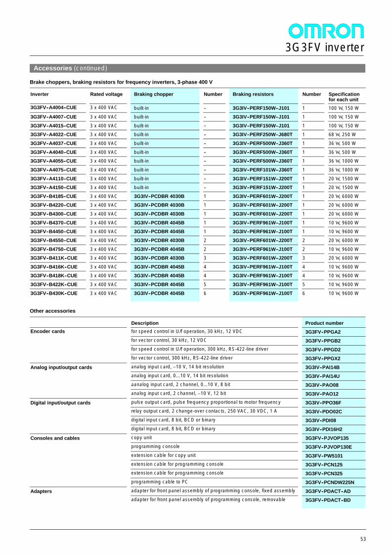
3G3FV inverter
53
Accessories (continued)
Brake choppers, braking resistors for frequency inverters, 3-phase 400 V
Inverter Rated voltage Braking chopper Number Braking resistors Number Specificationfor each unit
3G3FV--A4004--CUE 3 x 400 VAC built-in -- 3G3IV--PERF150W--J101 1 100 W , 150 W3G3FV--A4007--CUE 3 x 400 VAC built-in -- 3G3IV--PERF150W--J101 1 100 W , 150 W
3G3FV--A4015--CUE 3 x 400 VAC built-in -- 3G3IV--PERF150W--J101 1 100 W , 150 W3G3FV--A4022--CUE 3 x 400 VAC built-in -- 3G3IV--PERF250W--J680T 1 68 W , 250 W
3G3FV--A4037--CUE 3 x 400 VAC built-in -- 3G3IV--PERF500W--J360T 1 36 W , 500 W
3G3FV--A4040--CUE 3 x 400 VAC built-in -- 3G3IV--PERF500W--J360T 1 36 W , 500 W3G3FV--A4055--CUE 3 x 400 VAC built-in -- 3G3IV--PERF500W--J360T 1 36 W , 1000 W
3G3FV--A4075--CUE 3 x 400 VAC built-in -- 3G3IV--PERF101W--J360T 1 36 W , 1000 W
3G3FV--A4110--CUE 3 x 400 VAC built-in -- 3G3IV--PERF151W--J200T 1 20 W , 1500 W3G3FV--A4150--CUE 3 x 400 VAC built-in -- 3G3IV--PERF151W--J200T 1 20 W , 1500 W
3G3FV--B4185--CUE 3 x 400 VAC 3G3IV--PCDBR 4030B 1 3G3IV--PERF601W--J200T 1 20 W , 6000 W3G3FV--B4220--CUE 3 x 400 VAC 3G3IV--PCDBR 4030B 1 3G3IV--PERF601W--J200T 1 20 W , 6000 W
3G3FV--B4300--CUE 3 x 400 VAC 3G3IV--PCDBR 4030B 1 3G3IV--PERF601W--J200T 1 20 W , 6000 W
3G3FV--B4370--CUE 3 x 400 VAC 3G3IV--PCDBR 4045B 1 3G3IV--PERF961W--J100T 1 10 W , 9600 W3G3FV--B4450--CUE 3 x 400 VAC 3G3IV--PCDBR 4045B 1 3G3IV--PERF961W--J100T 1 10 W , 9600 W
3G3FV--B4550--CUE 3 x 400 VAC 3G3IV--PCDBR 4030B 2 3G3IV--PERF601W--J200T 2 20 W , 6000 W
3G3FV--B4750--CUE 3 x 400 VAC 3G3IV--PCDBR 4045B 2 3G3IV--PERF961W--J100T 2 10 W , 9600 W3G3FV--B411K--CUE 3 x 400 VAC 3G3IV--PCDBR 4030B 3 3G3IV--PERF601W--J200T 3 20 W , 6000 W
3G3FV--B416K--CUE 3 x 400 VAC 3G3IV--PCDBR 4045B 4 3G3IV--PERF961W--J100T 4 10 W , 9600 W3G3FV--B418K--CUE 3 x 400 VAC 3G3IV--PCDBR 4045B 4 3G3IV--PERF961W--J100T 4 10 W , 9600 W
3G3FV--B422K--CUE 3 x 400 VAC 3G3IV--PCDBR 4045B 5 3G3IV--PERF961W--J100T 5 10 W , 9600 W
3G3FV--B430K--CUE 3 x 400 VAC 3G3IV--PCDBR 4045B 6 3G3IV--PERF961W--J100T 6 10 W , 9600 W
Other accessories
Description Product numberEncoder cards for speed control in U/f operation, 30 kHz, 12 VDC 3G3FV--PPGA2Encoder cards
for vector control, 30 kHz, 12 VDC 3G3FV--PPGB2for speed control in U/f operation, 300 kHz, RS-422-line driver 3G3FV--PPGD2for vector control, 300 kHz, RS-422-line driver 3G3FV--PPGX2
Analog input/output cards analog input card, ±10 V, 14 bit resolution 3G3IV--PAI14BAnalog input/output cardsanalog input card, 0...10 V, 14 bit resolution 3G3IV--PAI14Uaanalog input card, 2 channel, 0...10 V, 8 bit 3G3IV--PAO08analog input card, 2 channel, ±10 V, 12 bit 3G3IV--PAO12
Digital input/output cards pulse output card, pulse frequency proportional to motor frequency 3G3IV--PPO36FDigital input/output cardsrelay output card, 2 change-over contacts, 250 VAC, 30 VDC, 1 A 3G3IV--PDO02Cdigital input card, 8 bit, BCD or binary 3G3IV--PDI08digital input card, 8 bit, BCD or binary 3G3IV--PDI16H2
Consoles and cables copy unit 3G3FV--PJVOP135Consoles and cablesprogramming console 3G3FV--PJVOP130Eextension cable for copy unit 3G3FV--PW5101extension cable for programming console 3G3FV--PCN125extension cable for programming console 3G3FV--PCN325programming cable to PC 3G3FV--PCNDW225N
Adapters adapter for front panel assembly of programming console, fixed assembly 3G3FV--PDACT--ADAdaptersadapter for front panel assembly of programming console, removable 3G3FV--PDACT--BD
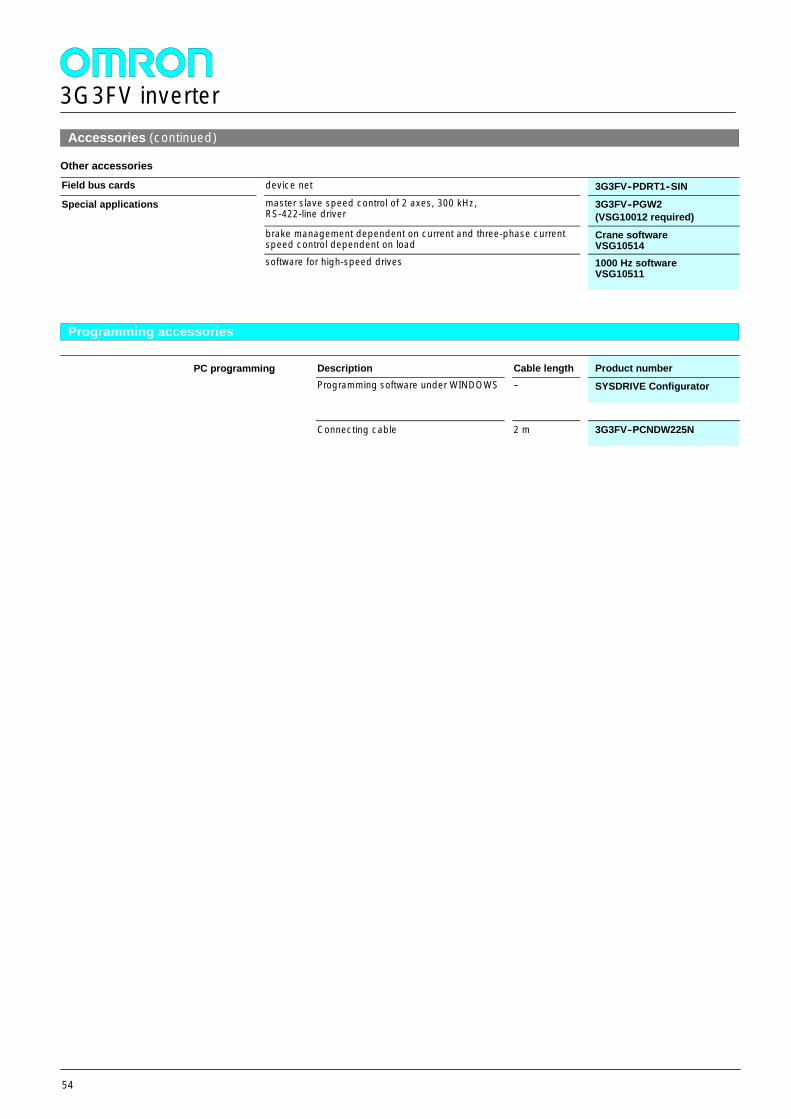
3G3FV inverter
54
Accessories (continued)
Other accessories
Field bus cards device net 3G3FV--PDRT1--SIN
Special applications master slave speed control of 2 axes, 300 kHz,RS-422-line driver
3G3FV--PGW2(VSG10012 required)
brake management dependent on current and three-phase currentspeed control dependent on load
Crane softwareVSG10514
software for high-speed drives 1000 Hz softwareVSG10511
Programming accessories
PC programming Description Cable length Product numberPC programmingProgramming software under WINDOWS -- SYSDRIVE Configurator
Connecting cable 2 m 3G3FV--PCNDW225N
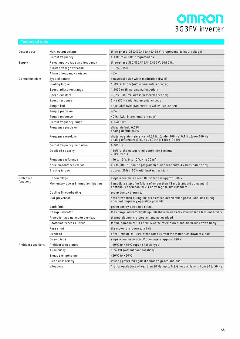
3G3FV inverter
55
Technical data
Output data Max. output voltage three-phase: 380/400/415/440/460 V (proportional to input voltage)Output data
Output frequency 0,1 Hz to 400 Hz programmable
Supply Rated input voltage and frequency three-phase 380/400/415/440/460 V, 50/60 HzSupply
Allowed voltage variation +10%, --15%
Allowed frequency variation ±5%
Control functions Type of control sinusoidal pulse width modulation (PWM)Control functions
Starting torque 150% at 0 rpm (with incremental encoder)
Speed adjustment range 1:1000 (with incremental encoder)
Speed constant ±0,2% (±0.02% with incremental encoder)
Speed response 5 Hz (30 Hz with incremental encoder)
Torque limit adjustable (with parameter, 4 values can be set)
Torque precision ±5%
Torque response 40 Hz (with incremental encoder)
Output frequency range 0,0-400 Hz
Frequency precision digital default: 0,01%analog default: 0,1%
Frequency resolution digital operator reference: (0,01 Hz (under 100 Hz) 0,1 Hz (over 100 Hz)analog reference: (0,03 Hz / 60 Hz (11 Bit + Code)
Output frequency resolution 0.001 Hz
Overload capacity 150% of the output rated current for 1 minute200% for 1 s
Frequency reference --10 to 10 V, 0 to 10 V, 4 to 20 mA
Acceleration/deceleration 0,0 to 6000 s (can be programmed independently, 4 values can be set)
Braking torque approx. 20% (150% with braking resistor)
Protectivefunctions
Undervoltage stops when main circuit DC voltage is approx. 380 VProtectivefunctions Momentary power interruption ridethru immediate stop after failure of longer than 15 ms (standard adjustment)
continuous operation for 2 s on voltage failure (standard)
Cooling fin overheating protection by thermistor
Stall prevention Stall prevention during the acceleration/deceleration phase, and also duringconstant frequency operation possible
Earth fault protection by electronic circuit
Charge indicator the charge indicator lights up until the intermediate circuit voltage falls under 50 V
Protection against motor overload thermo-electronic protection against overload
Short-time excess current for the duration of 1 s at 200% of the rated current the motor runs down freely
Fuse short the motor runs down to a halt
Overload after 1 minute at 150% of the rated current the motor runs down to a halt
Overvoltage stops when maincircuit DC voltage is approx. 820 V
Ambient conditions Ambient temperature --10°C to +45°C (open chassis type)Ambient conditions
Air humidity 90% RH (without condensation)
Storage temperature --20°C to +60°C
Place of assembly inside ( protected against corrosive gases and dust)
Vibrations 1 G for oscillations of less than 20 Hz, up to 0.2 G for oscillations from 20 to 50 Hz
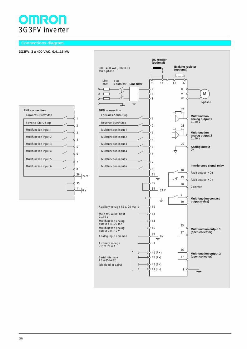
3G3FV inverter
56
Connections diagram
3G3FV, 3 x 400 VAC, 0,4...15 kW
18
19
20
Fault output (NO)
Fault output (NC)
Common
Interference signal relay
Forwards-Start/-Stop
Reverse-Start/-Stop
Multifunction input 1
Multifunction input 2
Line filter
380...460 VAC, 50/60 Hzthree-phase
1
2
3
4
5
R
+1
Braking resistor(optional)
MUVW
21
Multifunctionanalog output 10...10 V
3--phase
9
10Multifunction contactoutput (relay)
Multifunction input 3
6Multifunction input 4
35
36 24 V
15
13
14
16
Auxiliary voltage 15 V, 20 mA
Main ref. value input0...10 VMultifunction analogoutput 1 4...20 mAMultifunction analogoutput 2 0...10 V
40 (R+)41 (R--)
42 (S+)43 (S--)
Serial interfaceRS--485/--422(shielded in pairs)
+2
DC reactor(optional)
-- B1 B2Linefuse
Linecontactor
ST
E
NPN connection
E
35
11 0 V
Multifunction input 57
8Multifunction input 6
11
17
33
Analog input common
Auxiliary voltage--15 V, 20 mA
Forwards-Start/-Stop
Reverse-Start/-Stop
Multifunction input 1
Multifunction input 2
1
2
3
4
5Multifunction input 3
6Multifunction input 4
PNP connection
Multifunction input 57
8Multifunction input 6
36 24 V
23
Multifunctionanalog output 20...10 V
Analog output0V
22
25
27
26
37
Multifunction output 1(open collector)
Multifunction output 2(open collector)
0V
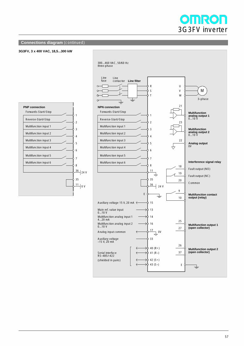
3G3FV inverter
57
Connections diagram (continued)
3G3FV, 3 x 400 VAC, 18,5...300 kW
18
19
20
Fault output (NO)
Fault output (NC)
Common
Interference signal relay
Forwards-Start/-Stop
Reverse-Start/-Stop
Multifunction input 1
Multifunction input 2
Line filter
380...460 VAC, 50/60 Hzthree-phase
1
2
3
4
5
RM
UVW
21
Multifunctionanalog output 10...10 V
3--phase
9
10Multifunction contactoutput (relay)
Multifunction input 3
6Multifunction input 4
35
36 24 V
15
13
14
16
Auxiliary voltage 15 V, 20 mA
Main ref. value input0...10 VMultifunction analog input 14...20 mAMultifunction analog input 20...10 V
40 (R+)41 (R--)
42 (S+)43 (S--)
Serial interfaceRS--485/--422(shielded in pairs)
Linefuse
Linecontactor
ST
E
NPN connection
E
35
11 0 V
Multifunction input 57
8Multifunction input 6
11
17
33
Analog input common
Auxiliary voltage--15 V, 20 mA
Forwards-Start/-Stop
Reverse-Start/-Stop
Multifunction input 1
Multifunction input 2
1
2
3
4
5Multifunction input 3
6Multifunction input 4
PNP connection
Multifunction input 57
8Multifunction input 6
36 24 V
23
Multifunctionanalog output 20...10 V
Analog output0V
22
25
27
26
37
Multifunction output 1(open collector)
Multifunction output 2(open collector)
0V
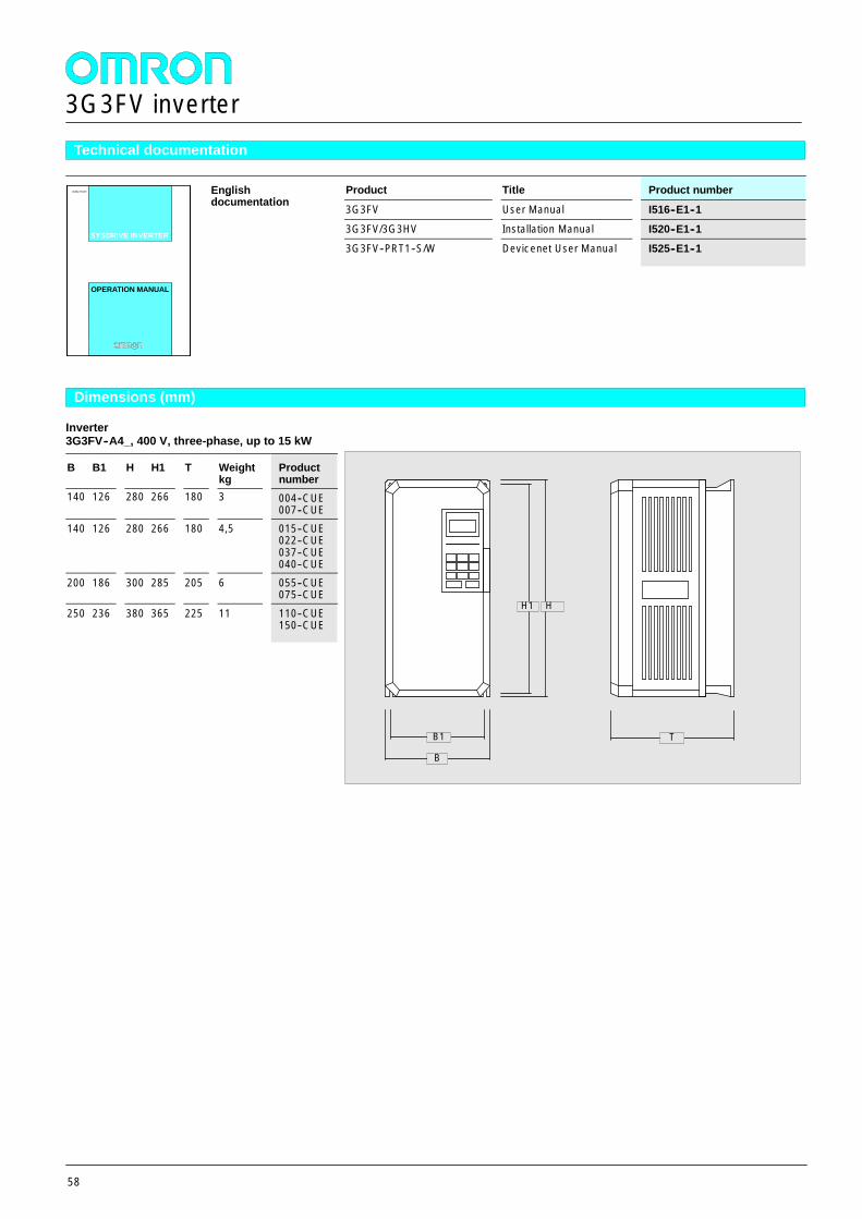
3G3FV inverter
58
Technical documentation
Englishdocumentation
Product Title Product numberEnglishdocumentation 3G3FV User Manual I516--E1--1
SYSDRIVE INVERTER3G3FV/3G3HV Installation Manual I520--E1--1
SYSDRIVE INVERTER
3G3FV--PRT1--S/W Devicenet User Manual I525--E1--1
OPERATION MANUALOPERATION MANUAL
Dimensions (mm)
Inverter3G3FV--A4_, 400 V, three-phase, up to 15 kW
B B1 H H1 T Weightkg
Productnumber
140 126 280 266 180 3 004--CUE007--CUE
140 126 280 266 180 4,5 015--CUE022--CUE037--CUE040--CUE
200 186 300 285 205 6 055--CUE075--CUE
250 236 380 365 225 11 110--CUE150--CUE
B
H1
T
H
B1
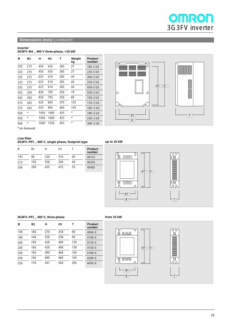
3G3FV inverter
59
Dimensions (mm) (continued)
Inverter3G3FV--B4_, 400 V three-phase, >15 kW
B B1 H H1 T Weightkg
Productnumber
325 275 450 435 285 27 185--CUE
325 275 450 435 285 27 220--CUE325 275 625 610 285 44 300--CUE
325 275 625 610 285 44 370--CUE325 275 625 610 285 44 450--CUE
455 350 820 795 350 79 550--CUE
455 350 820 795 350 80 750--CUE575 445 925 895 375 135 11K--CUE
575 445 925 895 400 145 16K--CUE
950 * 1450 1400 435 * 18K--CUE950 * 1450 1400 435 * 22K--CUE
960 * 1600 1550 455 * 30K--CUE* on demand
Line filter3G3FV--PFI_, 400 V, single phase, footprint type
B B1 H H1 T Productnumber
143 90 320 310 40 4012E
213 150 350 330 40 4025E266 200 435 415 55 4040E
3G3FV--PFI_, 400 V, three-phase
B B1 H H1 T Productnumber
140 106 270 258 90 4060--E
180 146 350 338 90 4100--E200 166 420 408 130 4120--E
200 166 420 408 130 4150--E
200 166 480 468 160 4180--E200 166 480 468 160 4280--E
250 170 567 560 205 4450--E
B
H1
TB1
H
B
H1
B1
H
T
up to 15 kW
B
H1
B1
H
T
from 15 kW

3G3FV inverter
60
Austria
+43 1 801900
Belgium
+32 2 466 2480
Czech
+42 0 2 6731 1254
Denmark
+45 4344 0011
Finland
+358 9 5495 800
France
+33 1 49 74 70 00
Germany
+49 2103 203-3
Hungary
+36 1 350 9532
Italy
+39 02 32 681
The Netherlands
+31 23 568 1100
Norway
+47 22 65 7500
Poland
+48 22 645 78 60
Portugal
+351 21 942 94 00
Spain
+34 91 377 7900
Sweden
+46 8 632 3500
Switzerland
+41 41 748 1313
Turkey
+90 126 326 2980/1/2
United Kingdom
+44 181 450 4646
Omron Europe B.V. - Wegalaan 67-69 - P.O. Box 13 - 2130 AA Hoofddorp - The Netherlands - Phone: +31 23 568 13 00 - Fax: +31 23 568 13 88 - www.eu.omron.com
Cat. No. X201-E2-02
Inverters
Selection G
uide